HOLIDAY DONATION DRIVE - SUPPORT MSW - DO YOUR PART TO KEEP THIS GREAT FORUM GOING! (Only 72 donations so far out of 49,000 members - Can we at least get 100? C'mon guys!)
×


halituzun
-
Posts
137 -
Joined
-
Last visited
Content Type
Profiles
Forums
Gallery
Events
Everything posted by halituzun
-
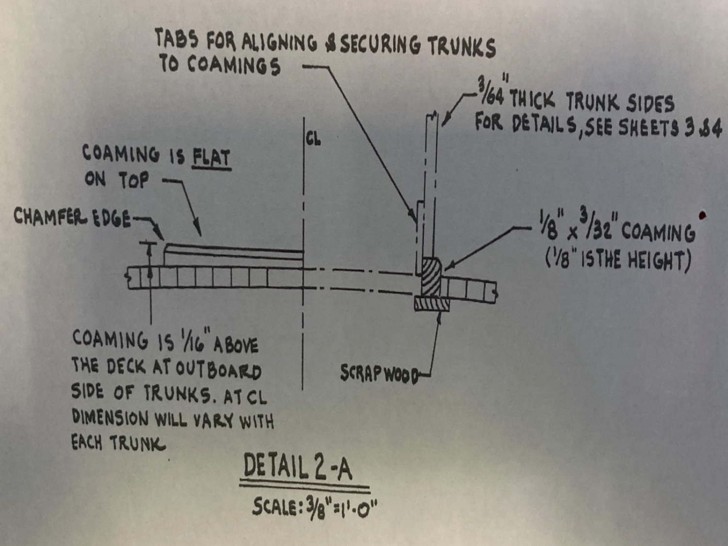
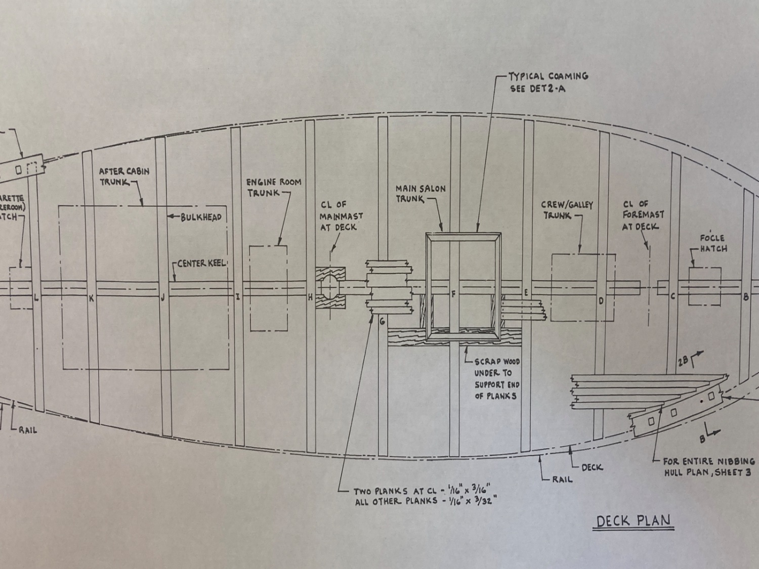
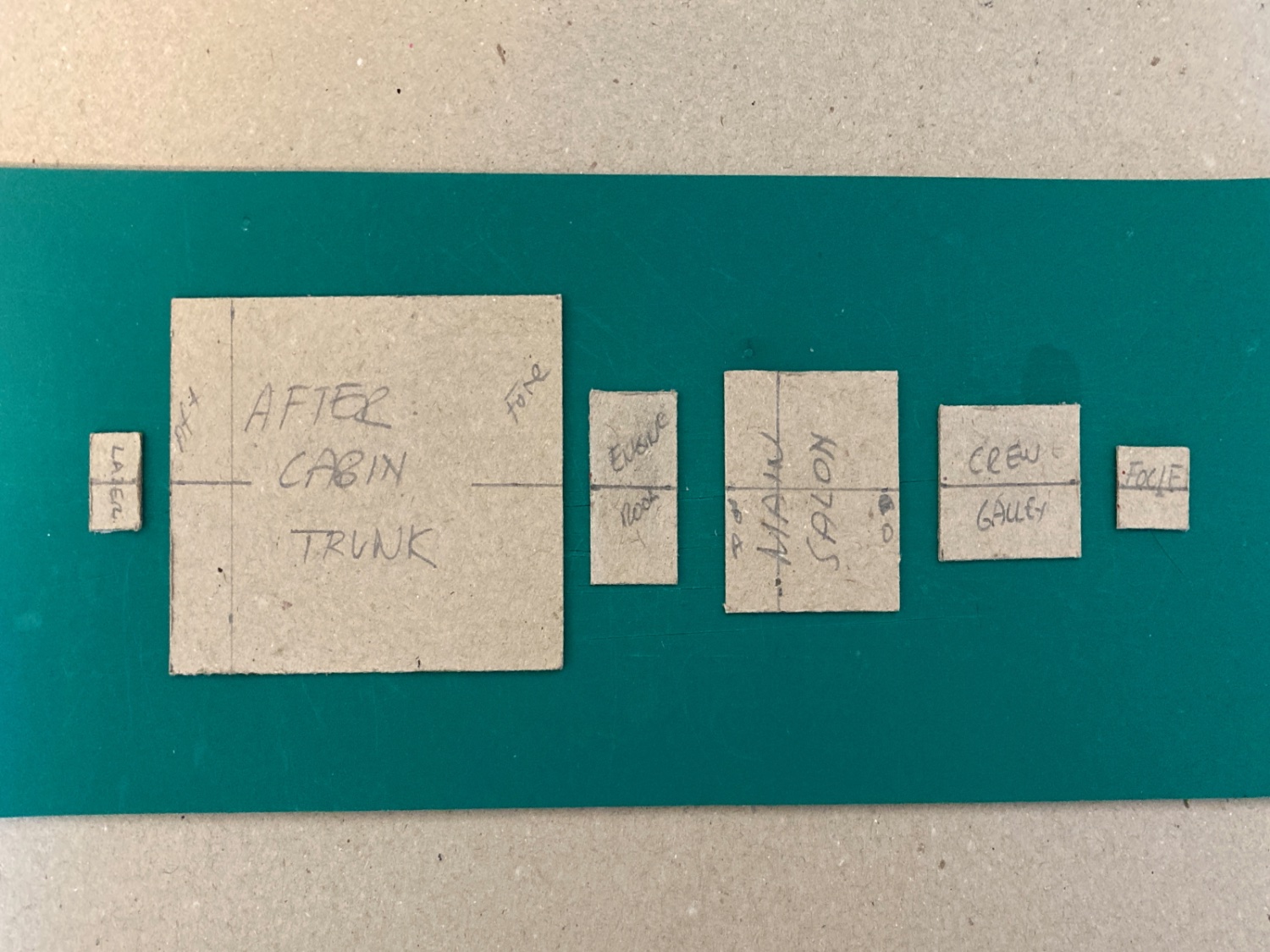
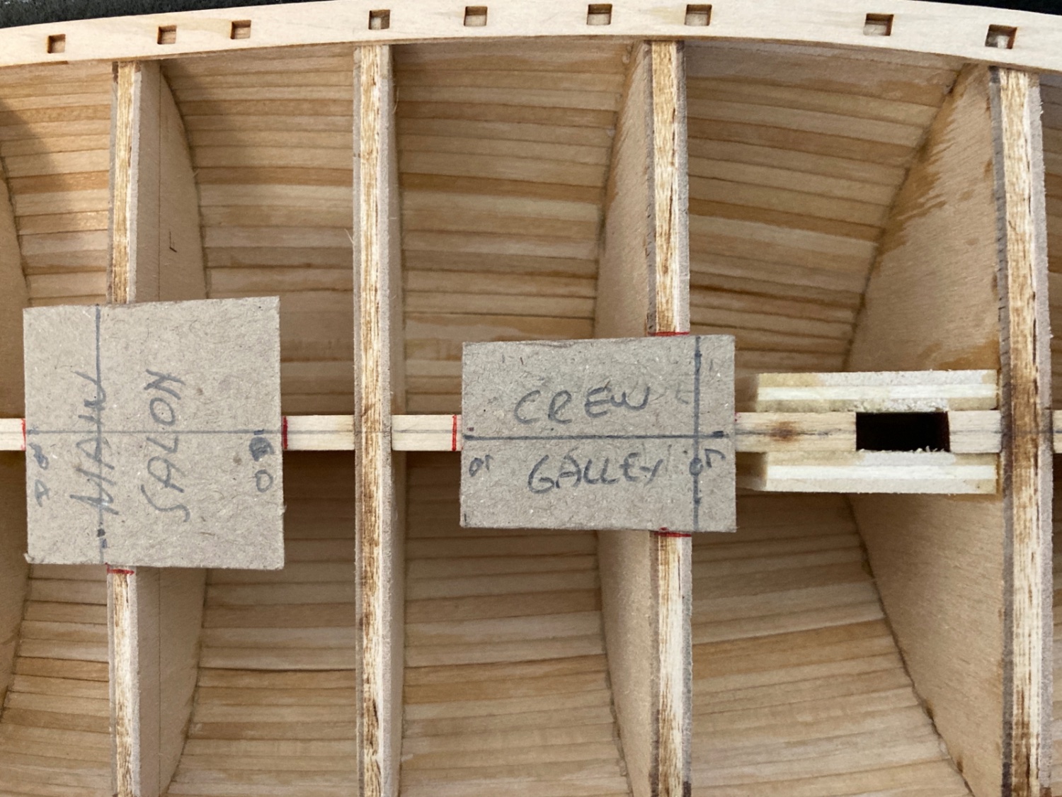
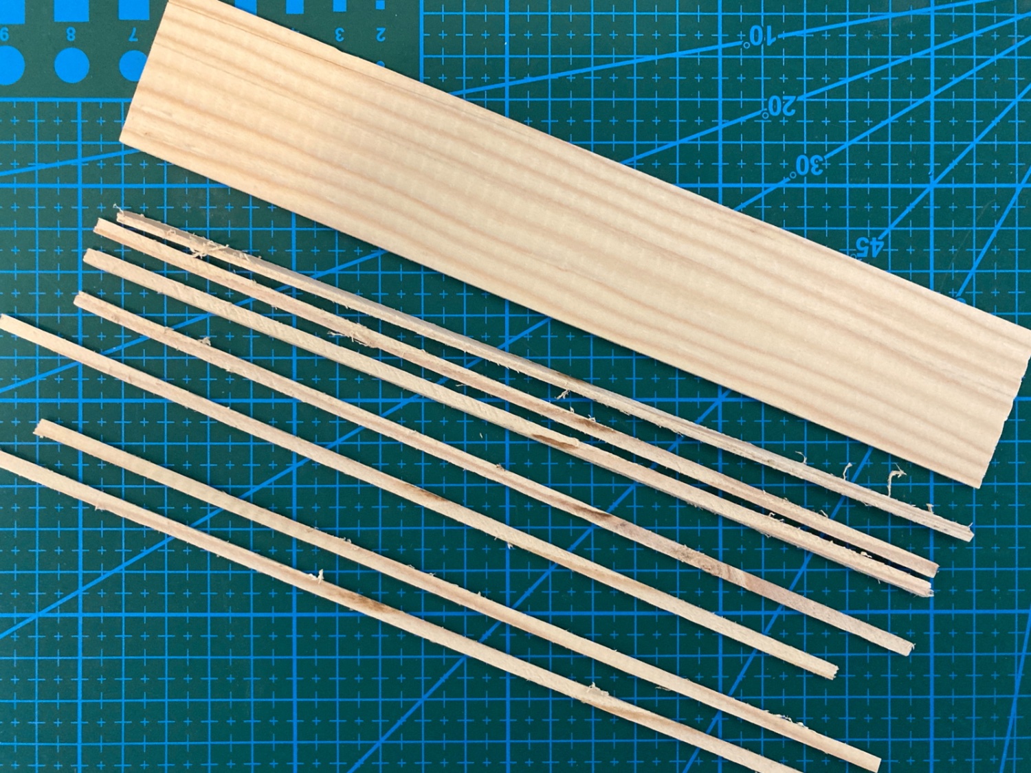
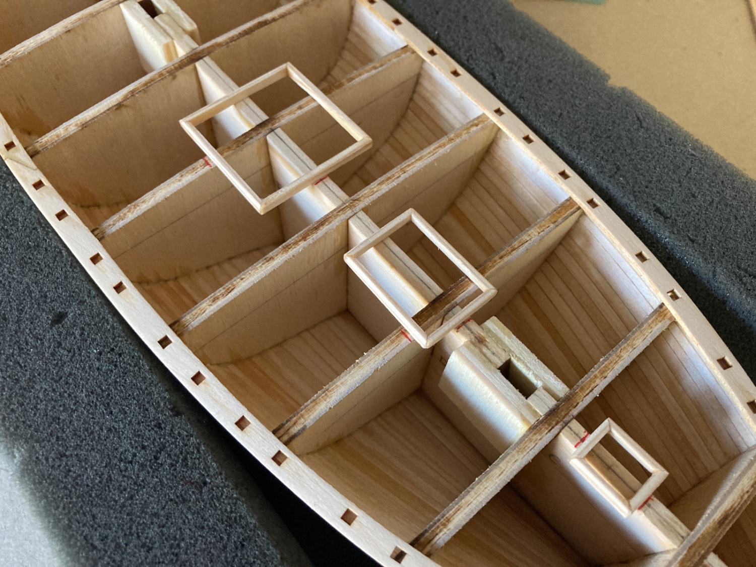
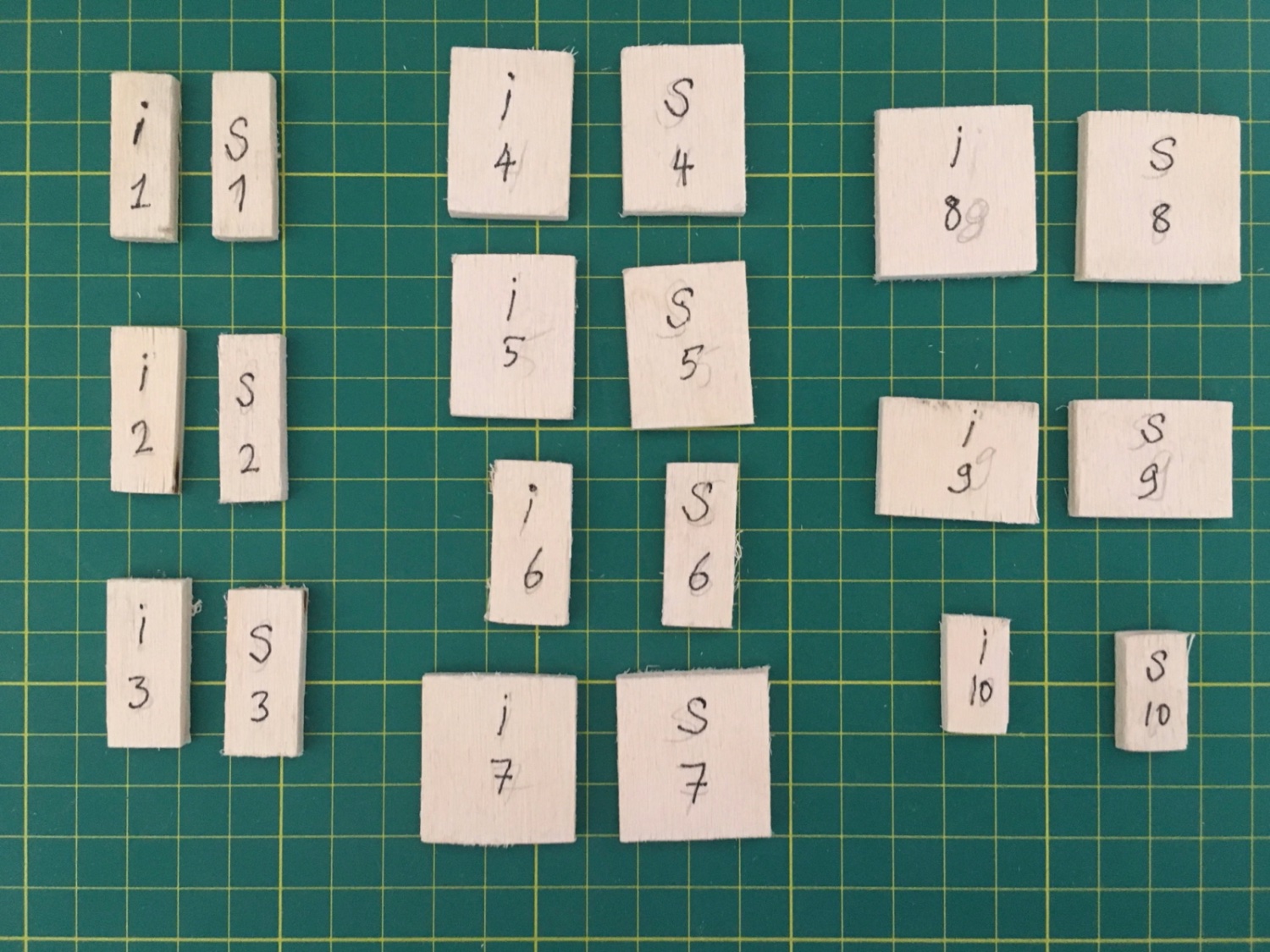
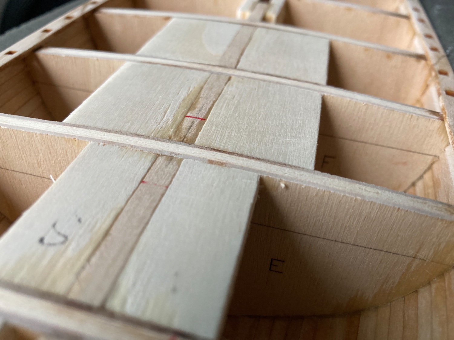
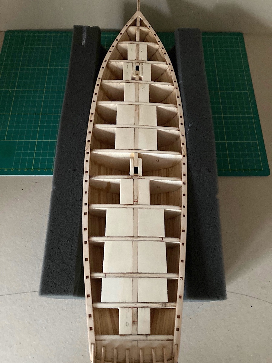
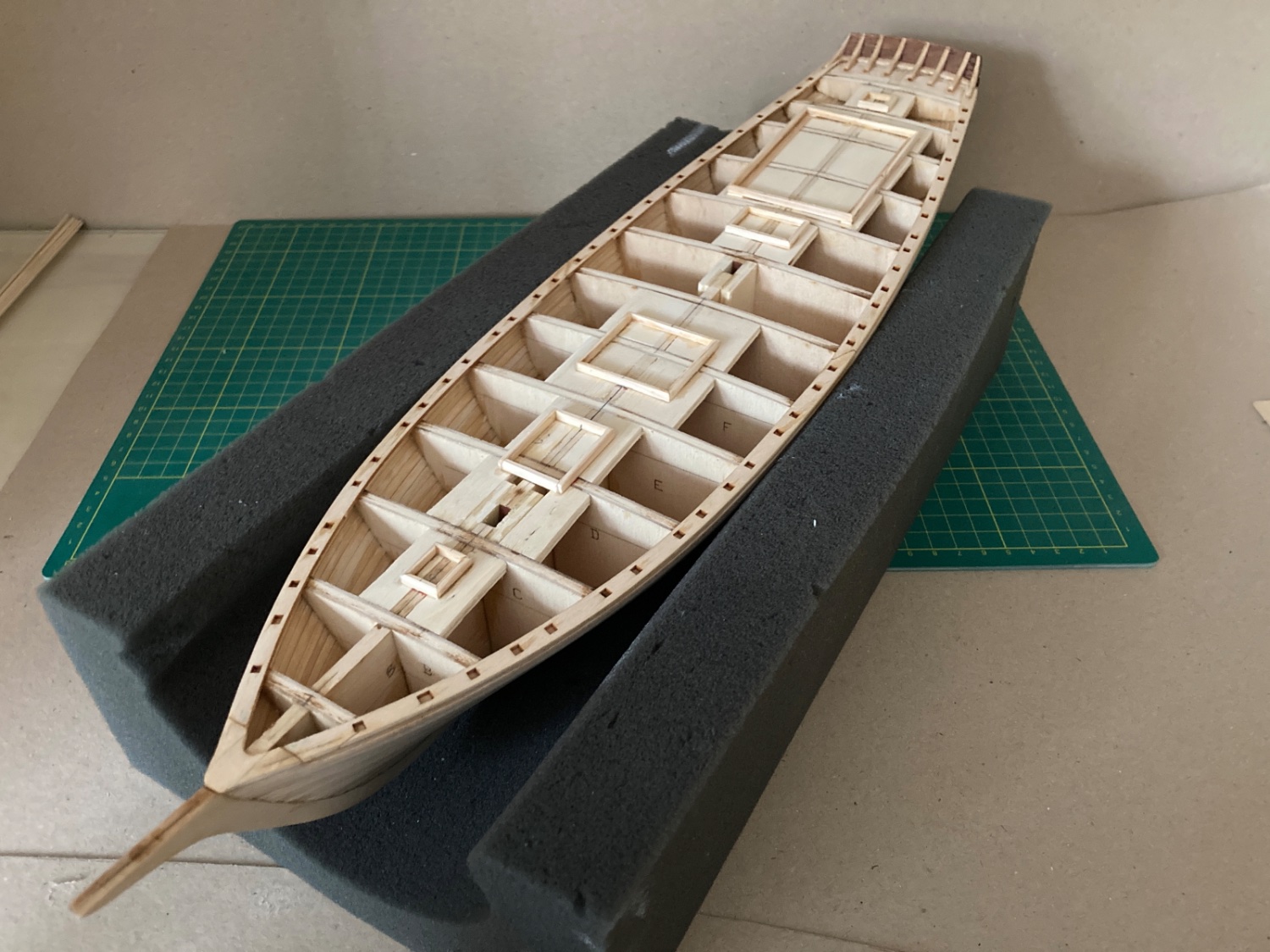
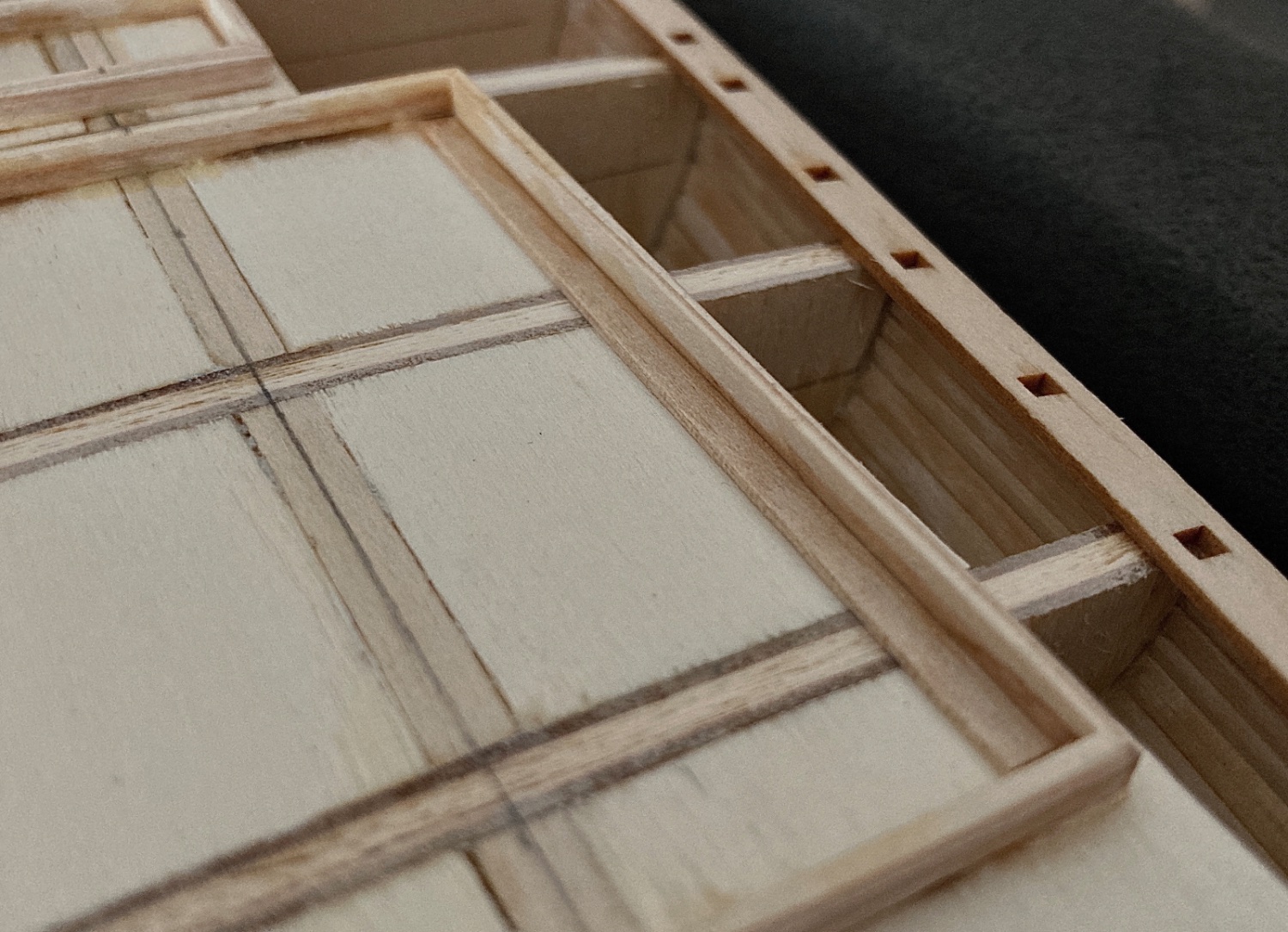
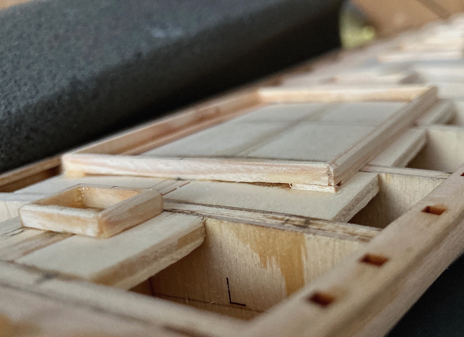
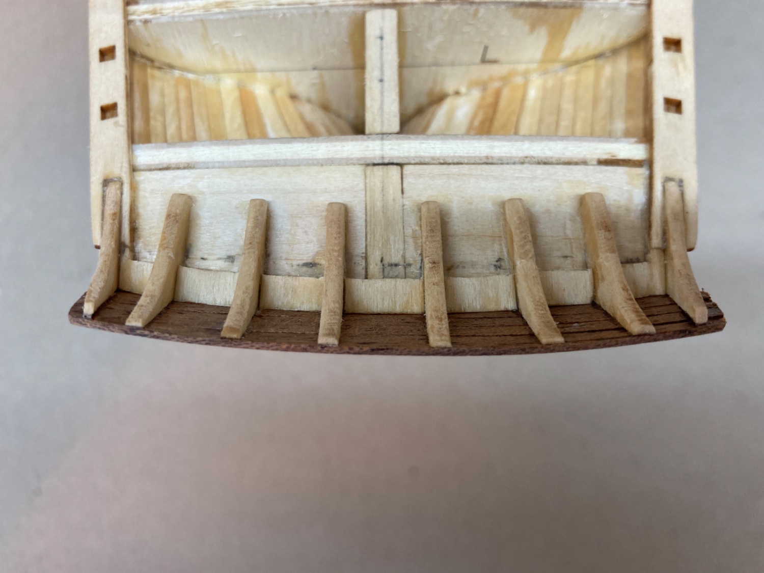
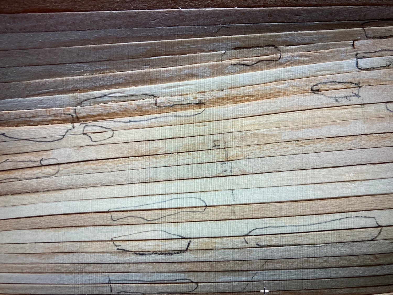
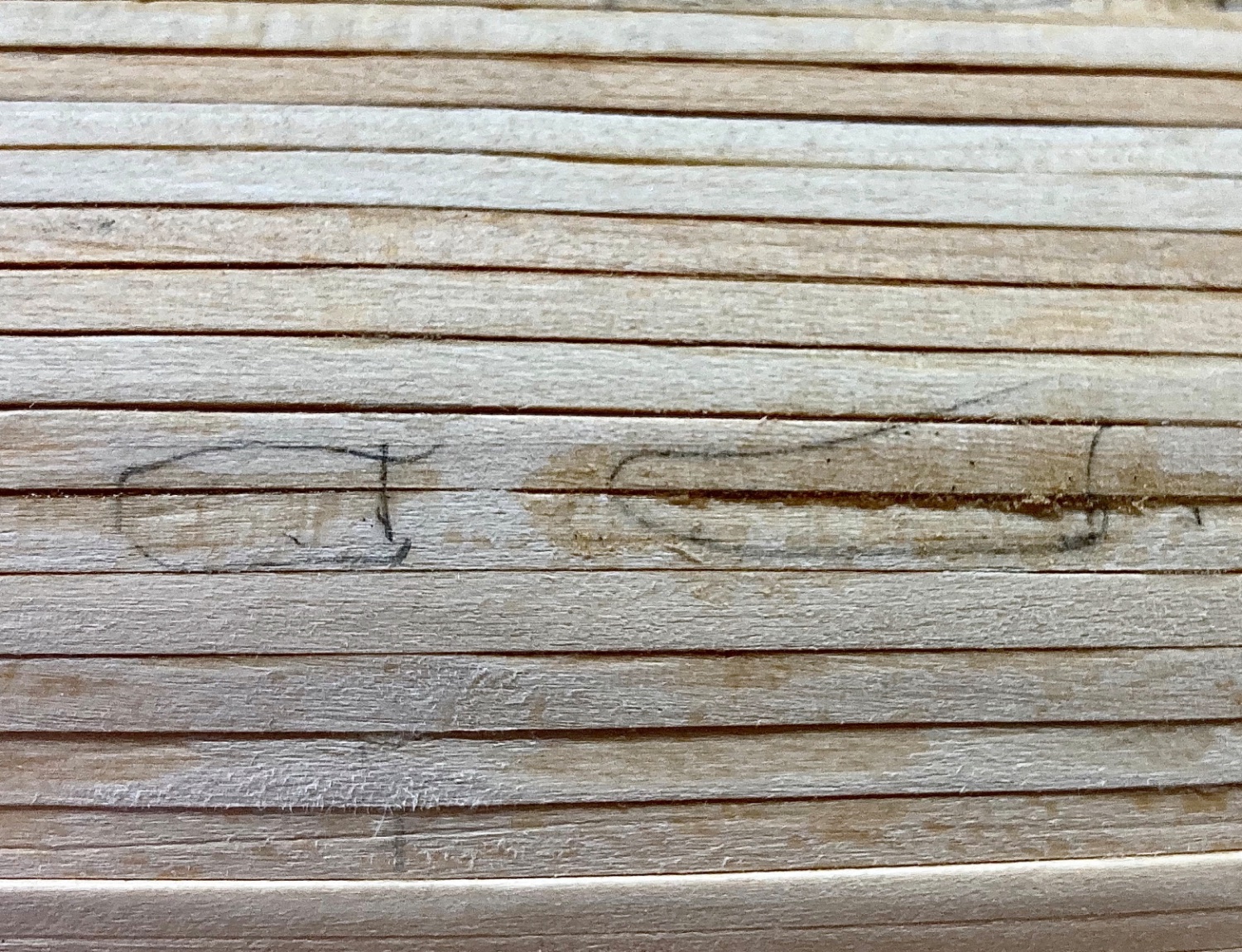
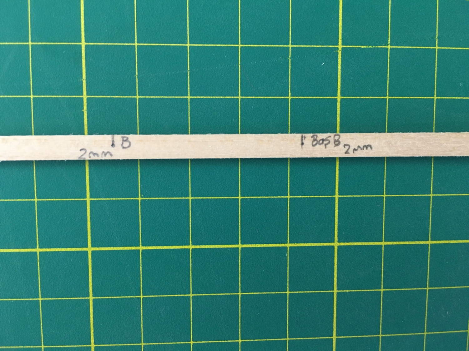
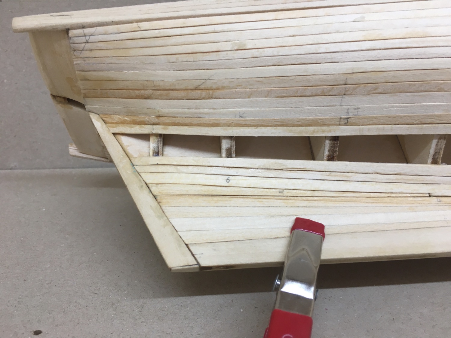
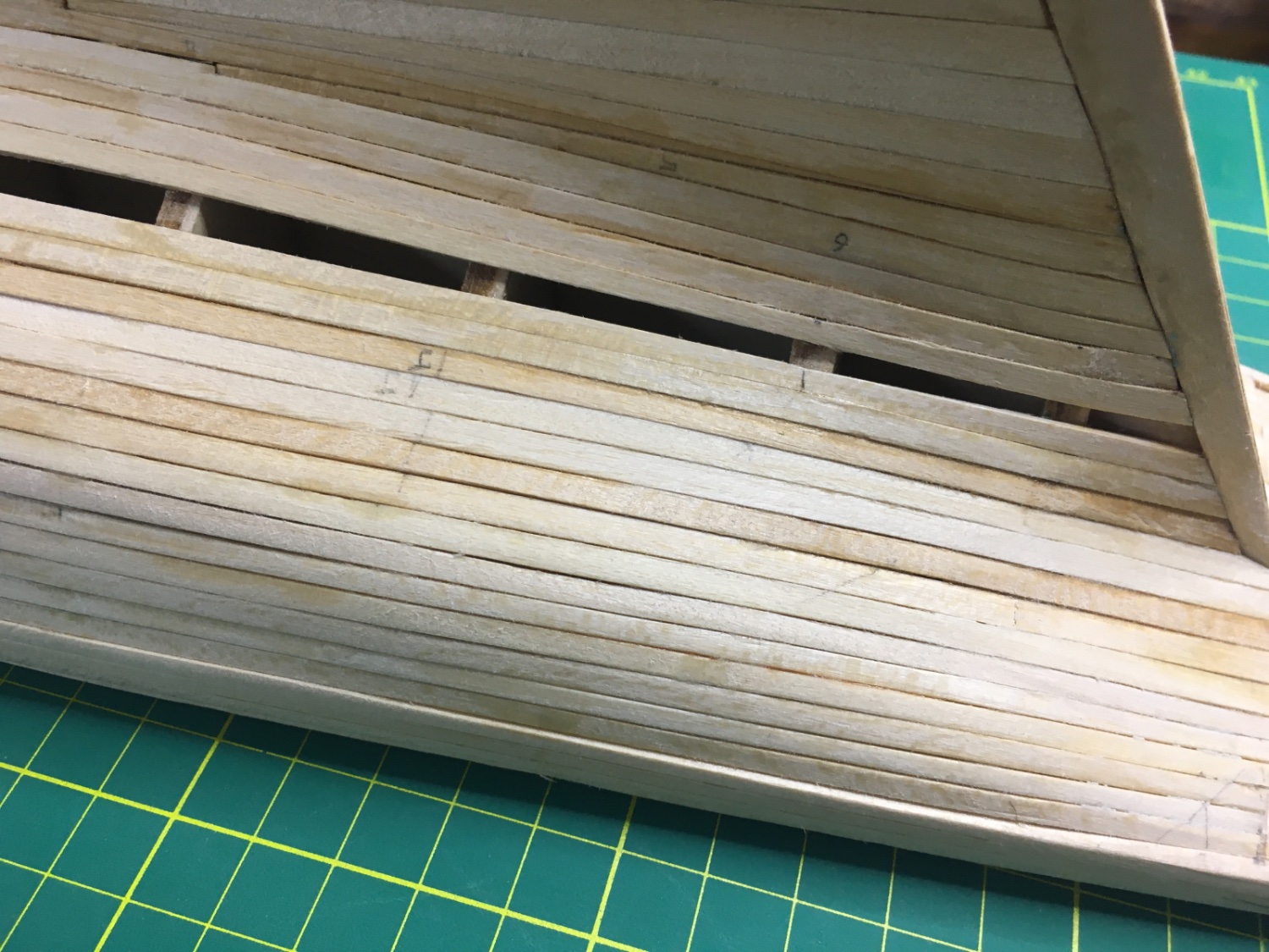
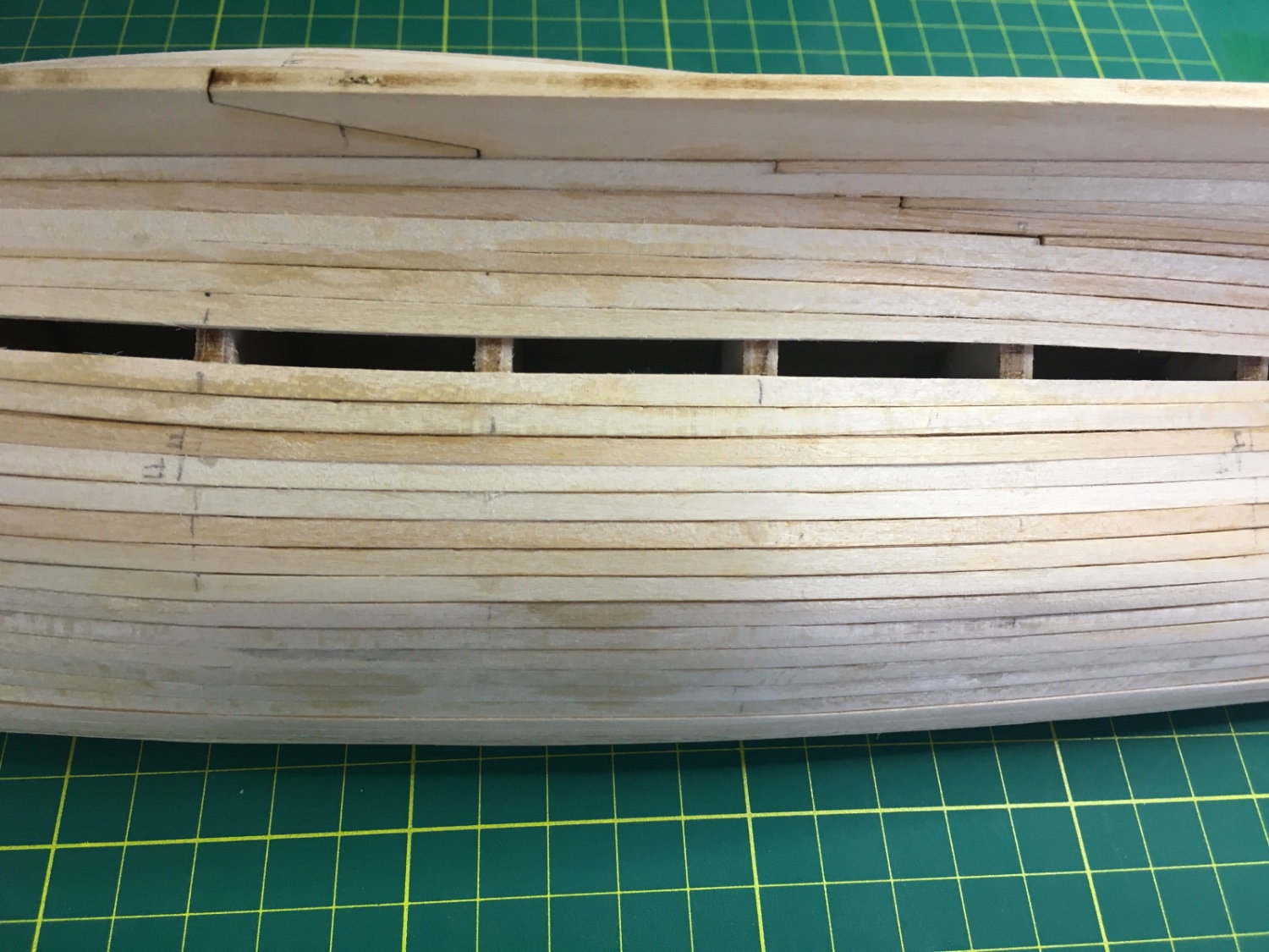
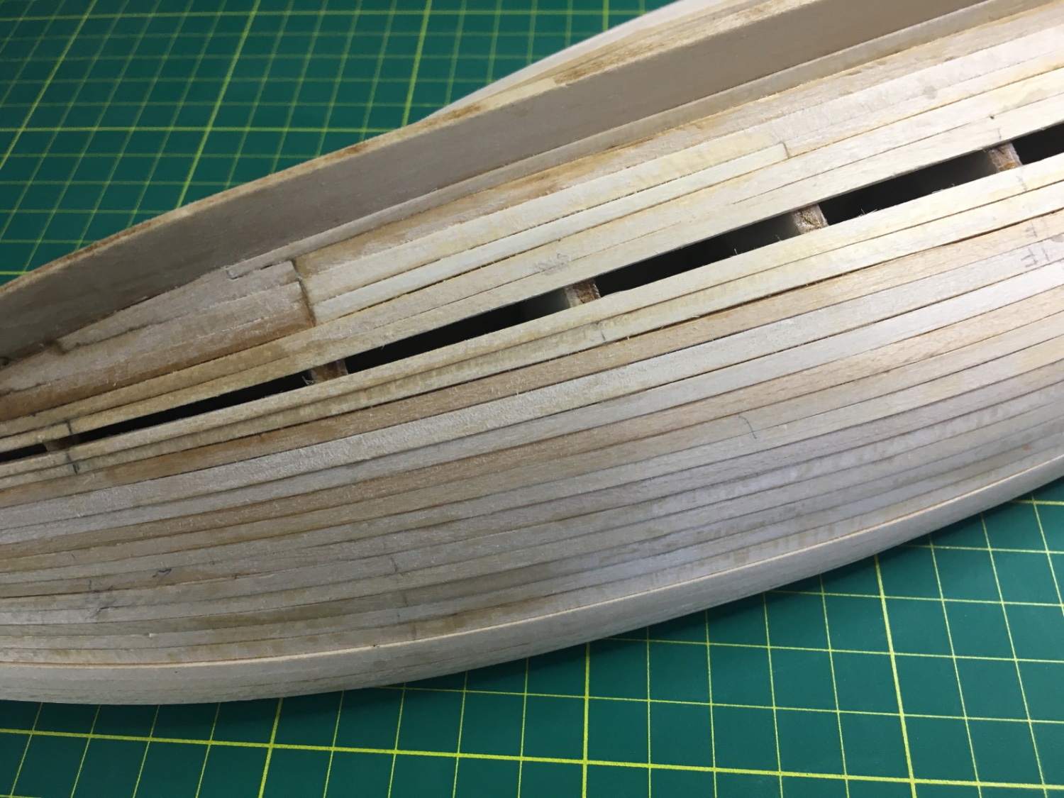
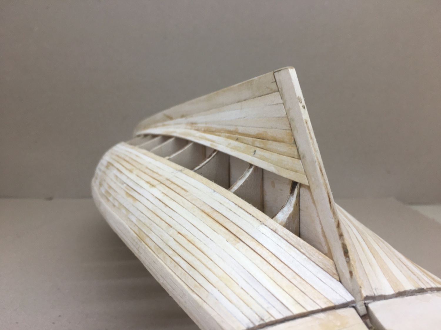
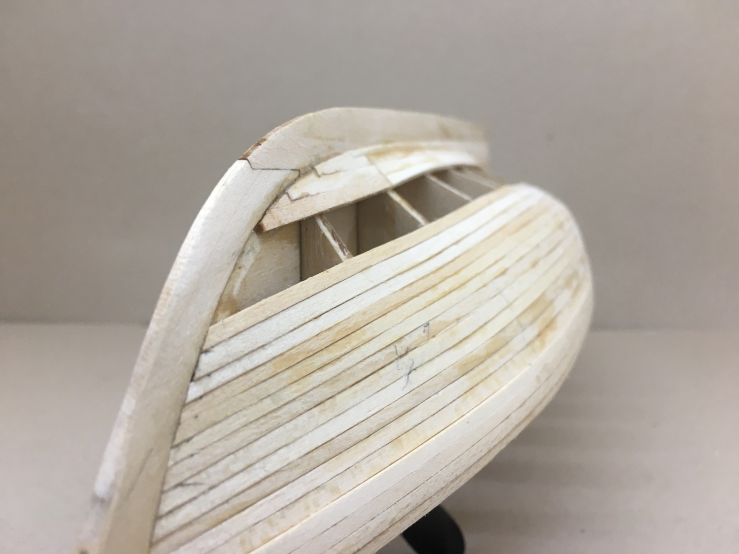
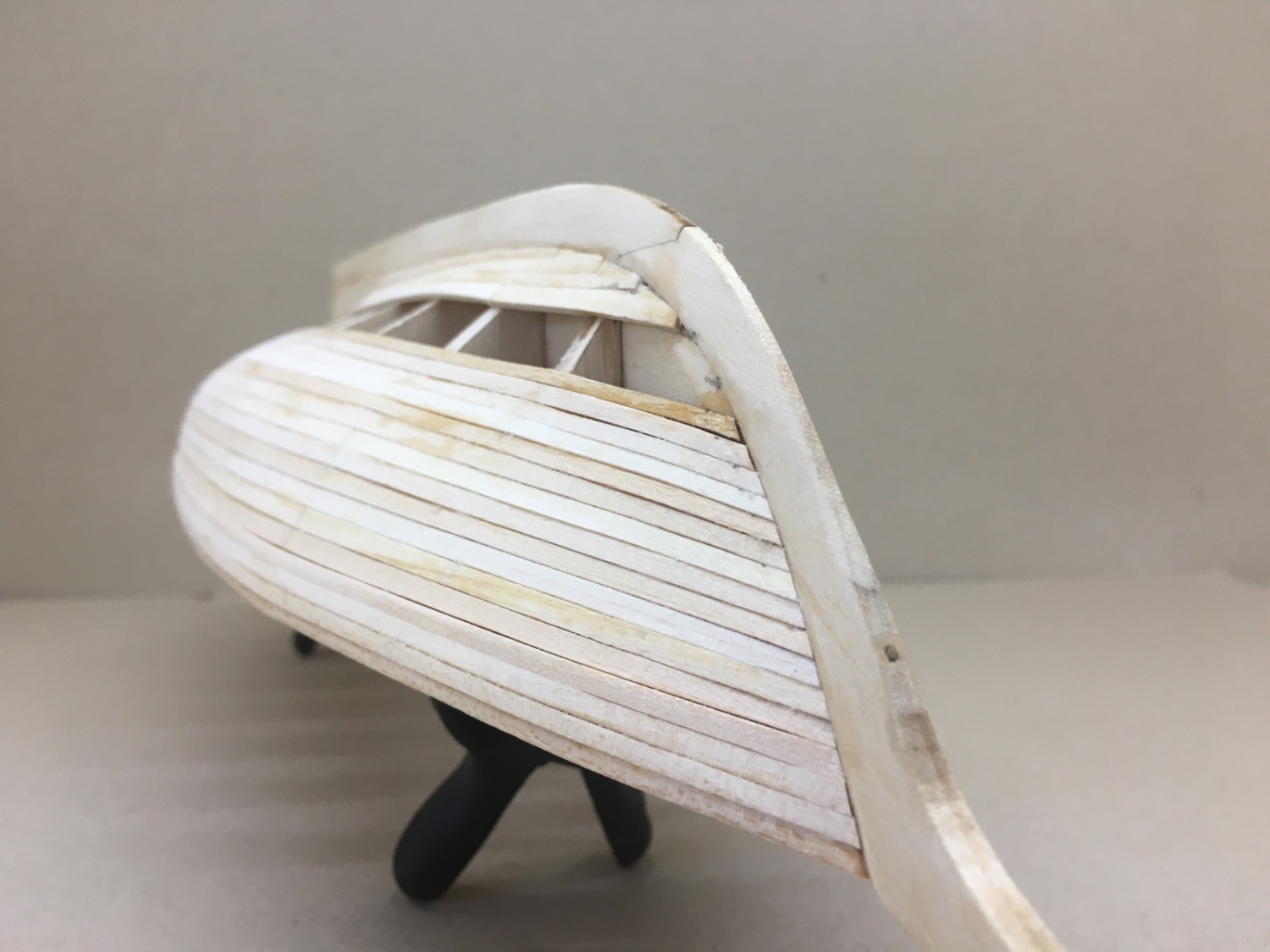
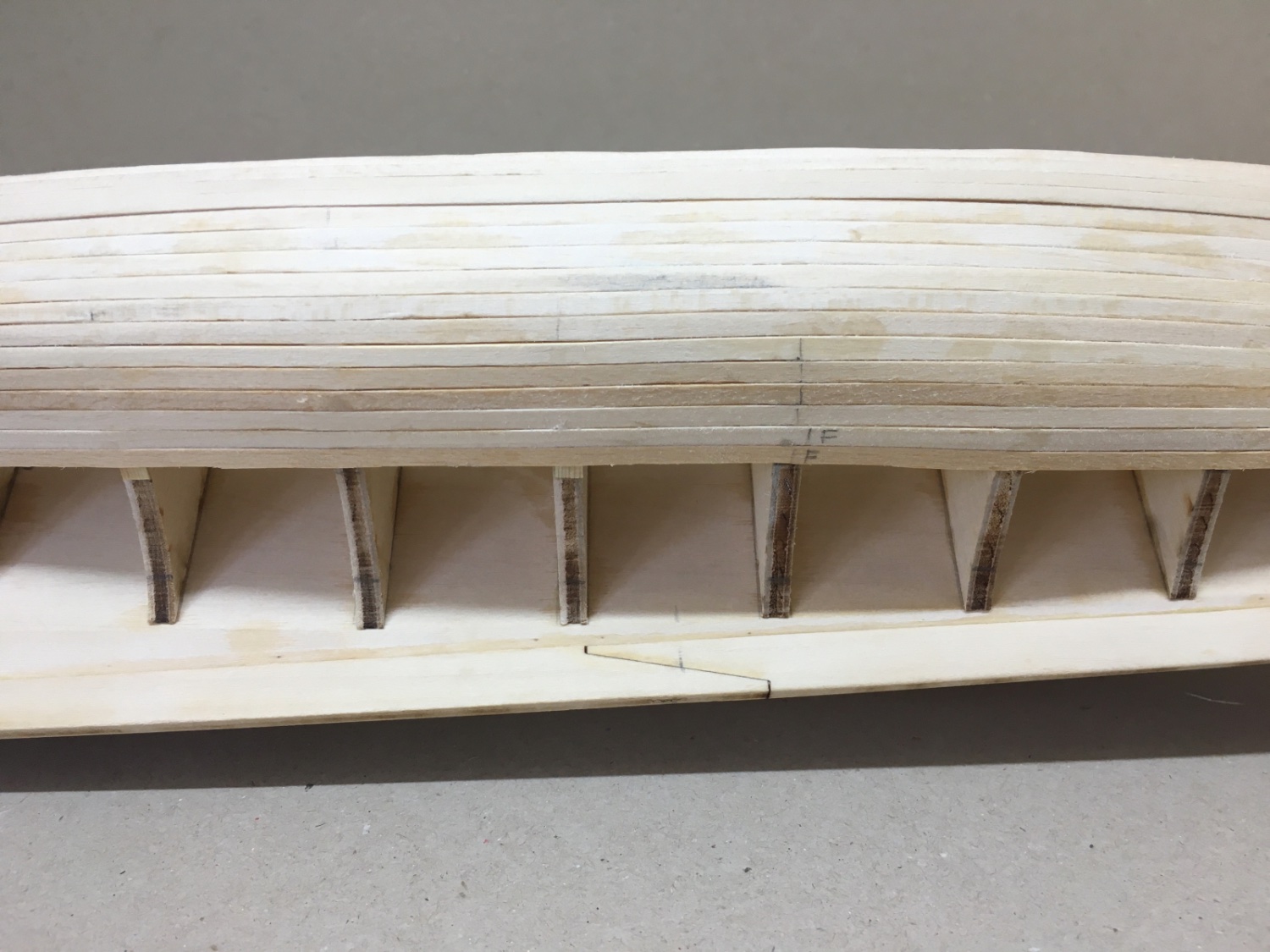
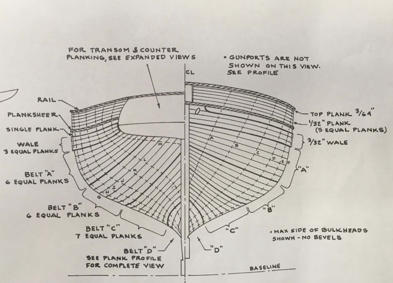
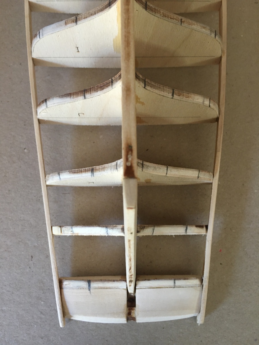
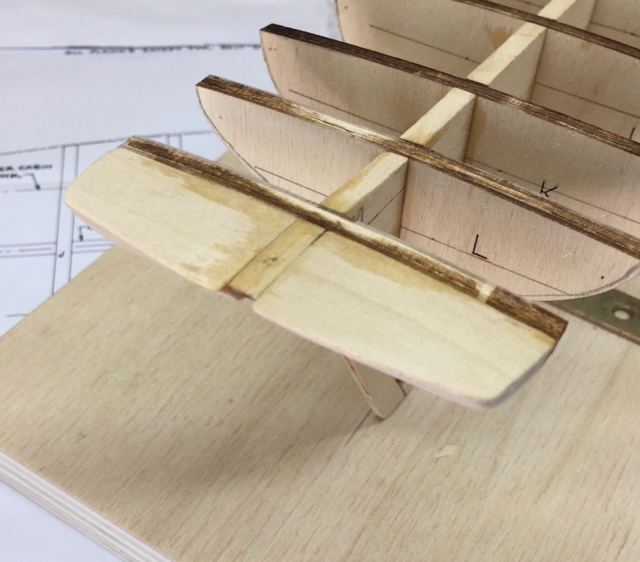
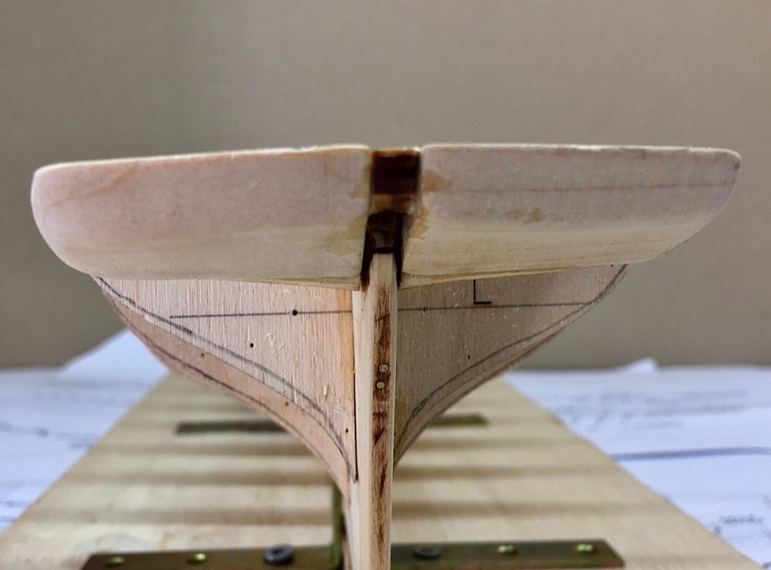
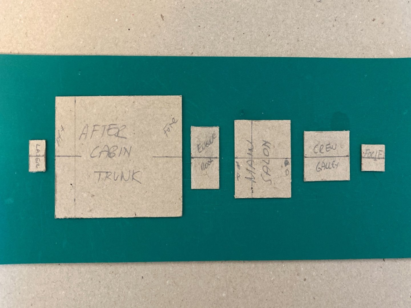
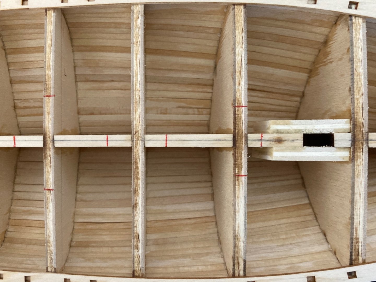
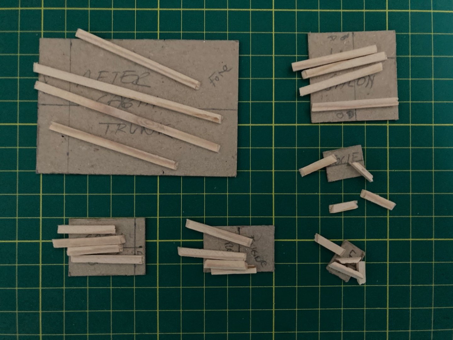
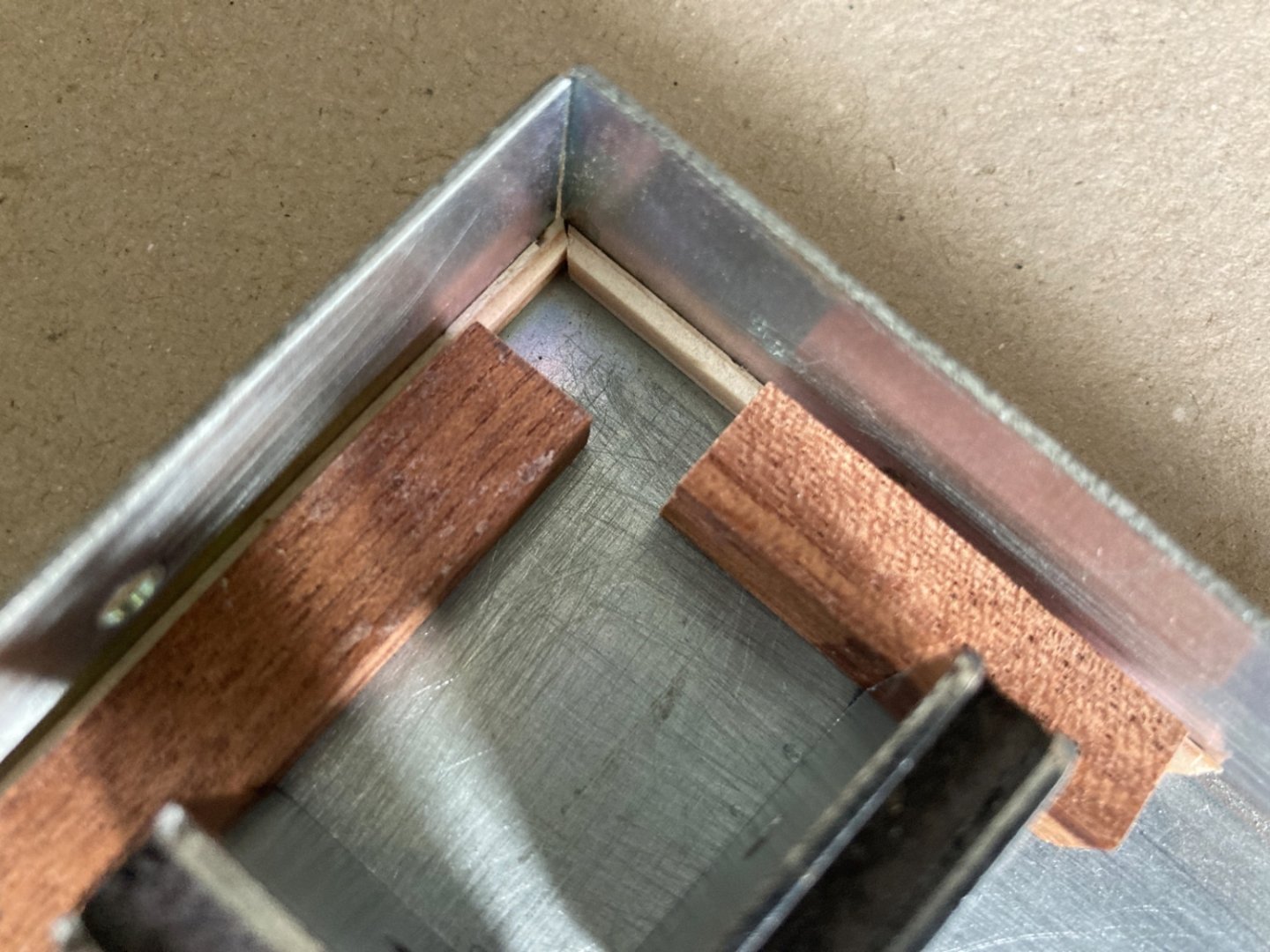
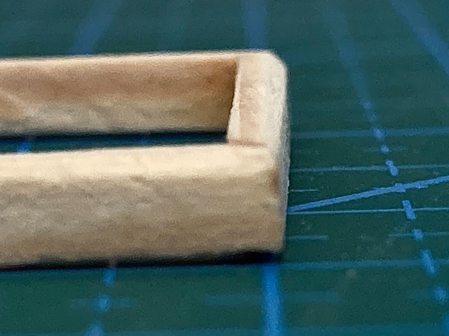
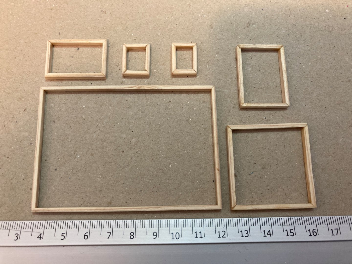
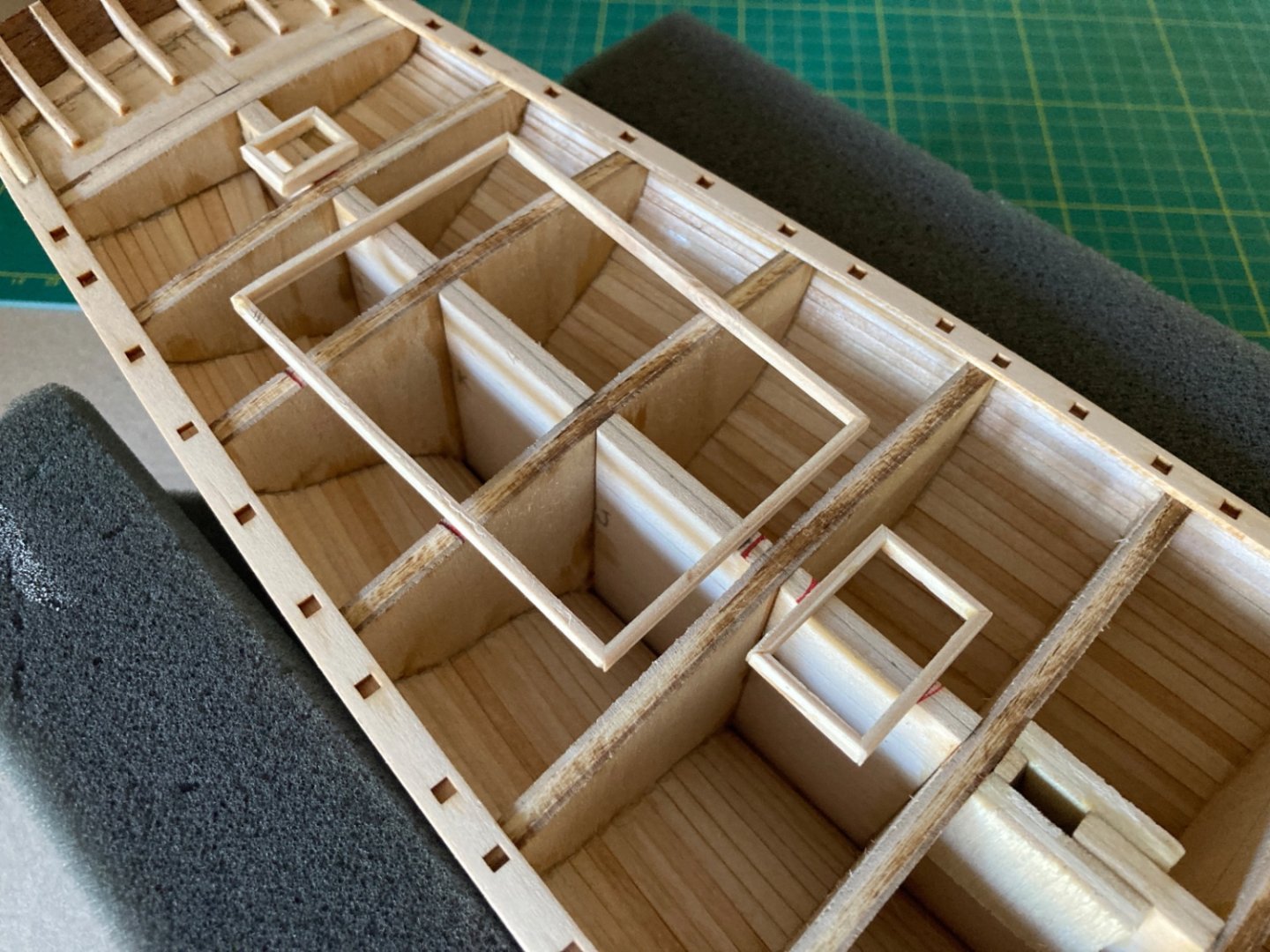
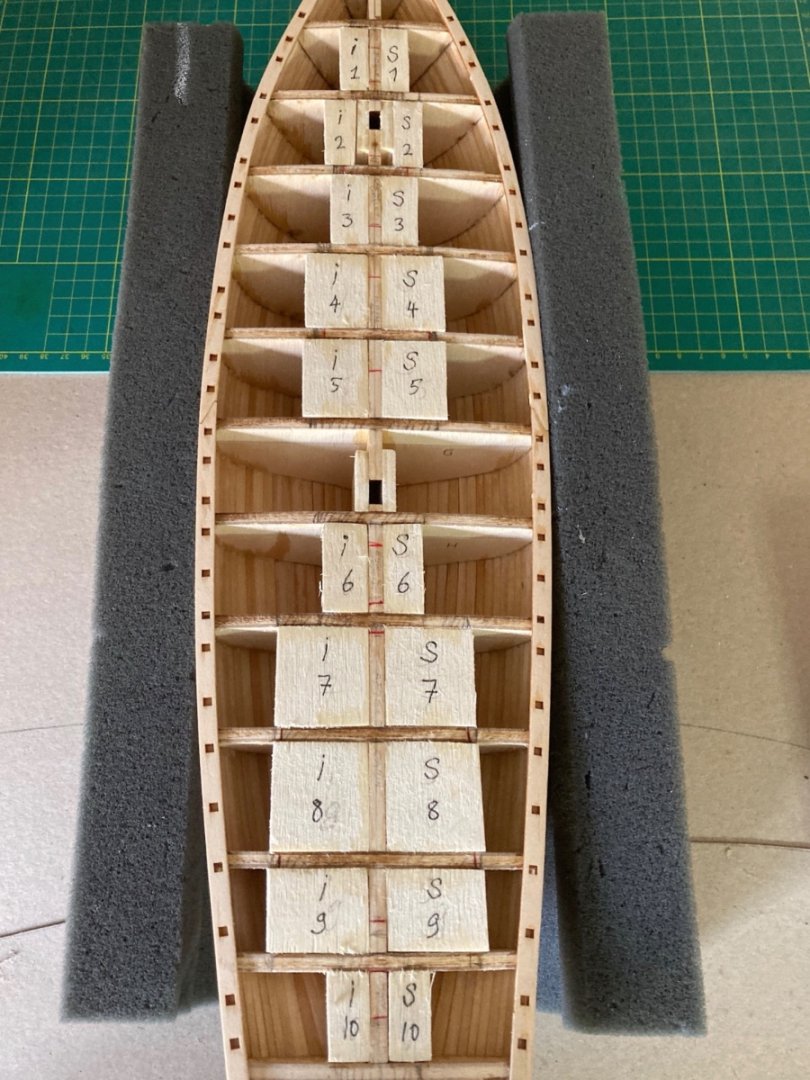
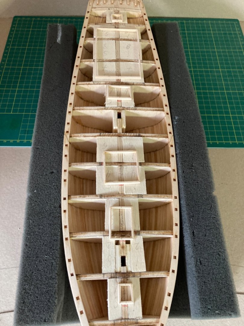
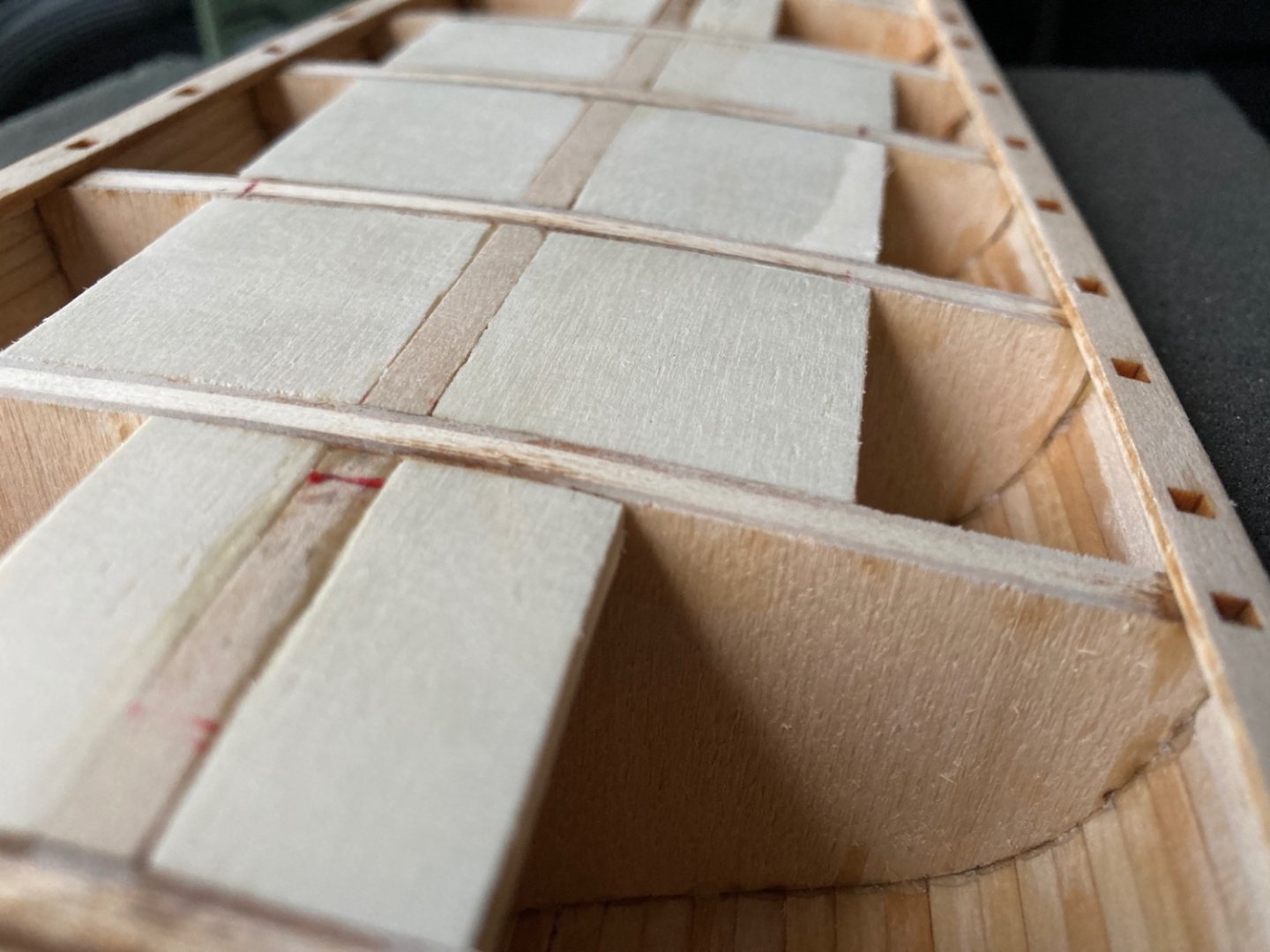
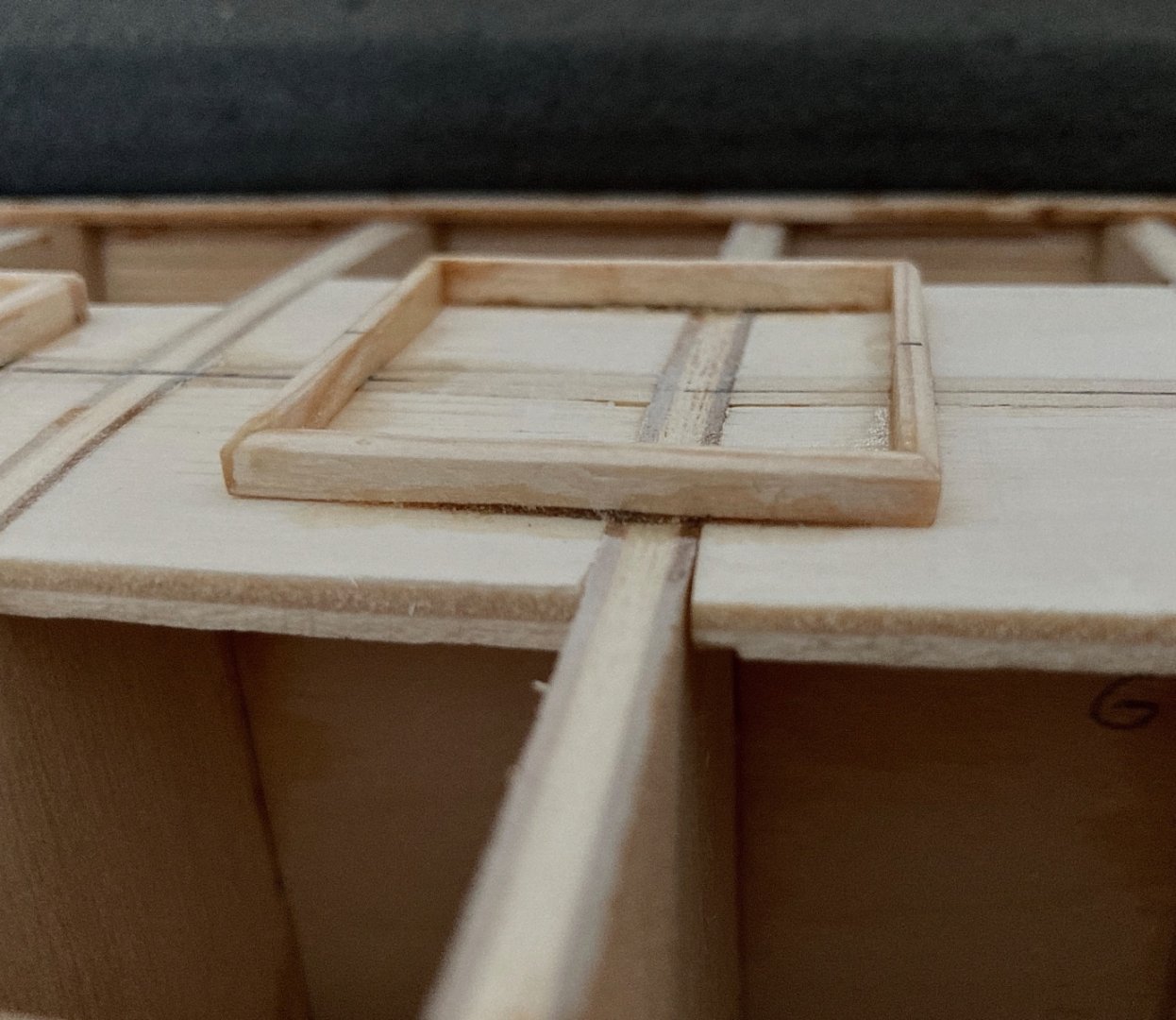
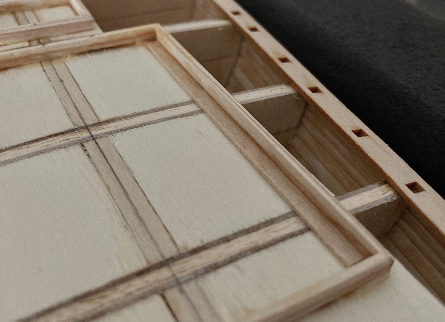
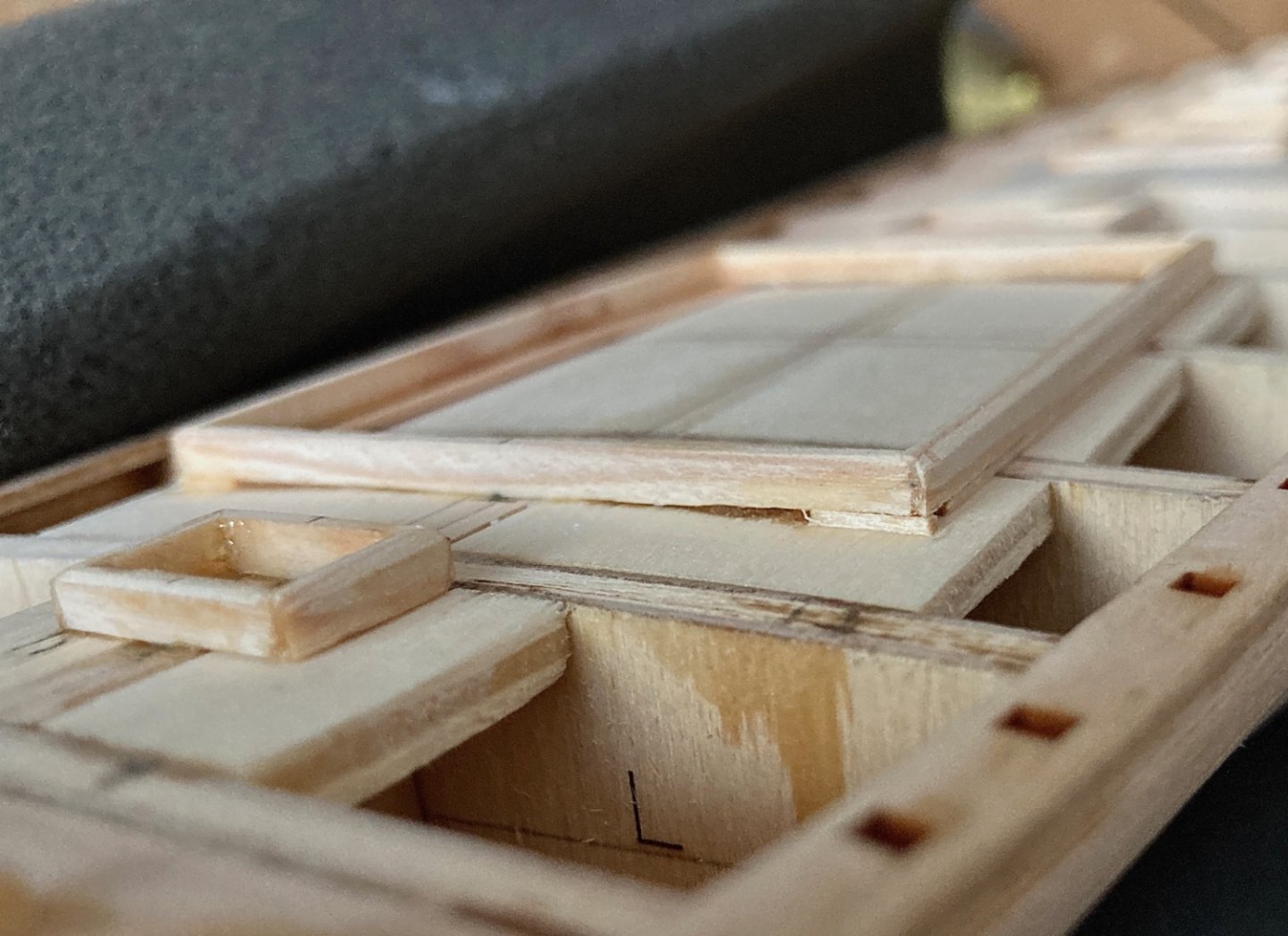
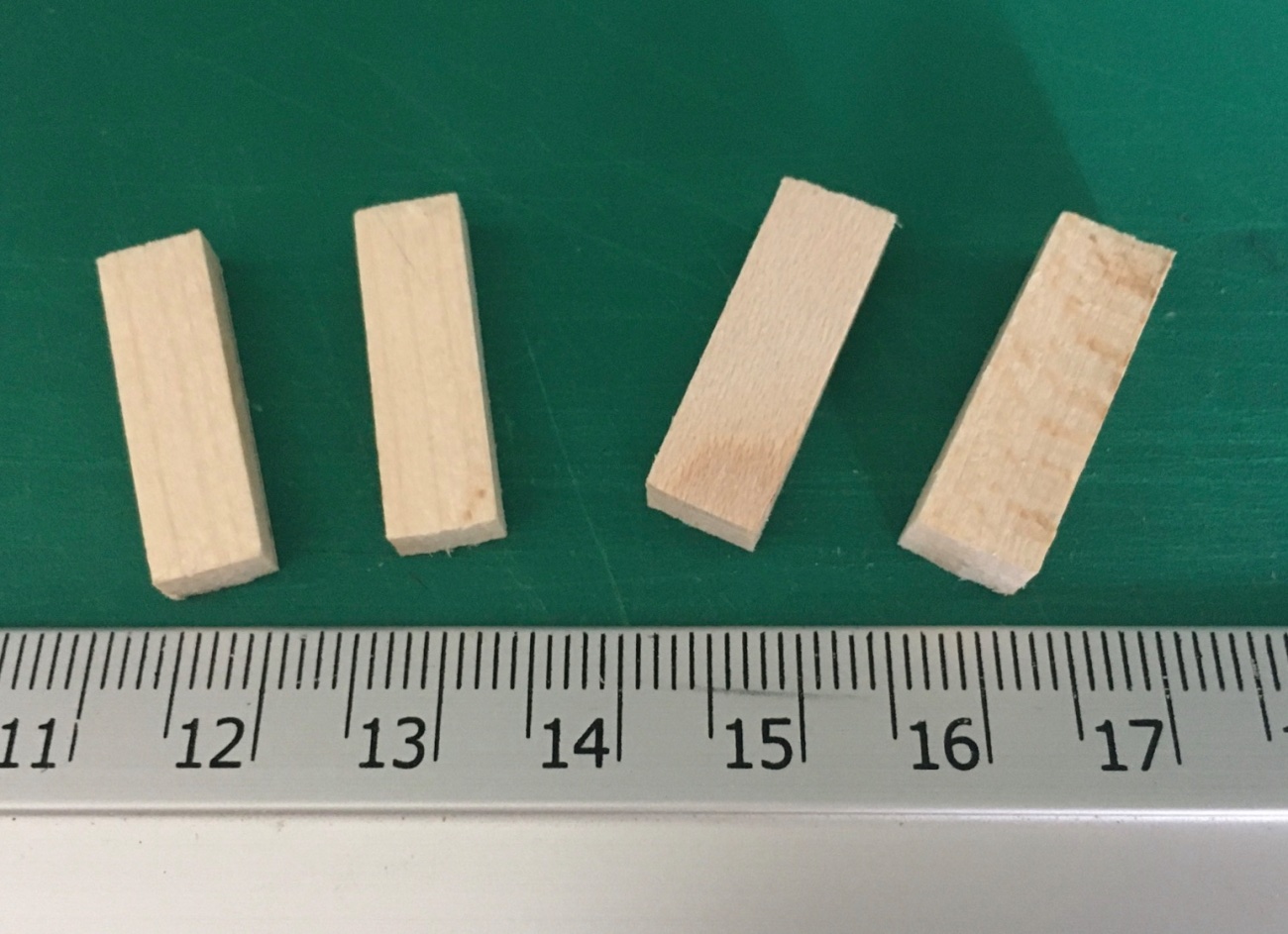
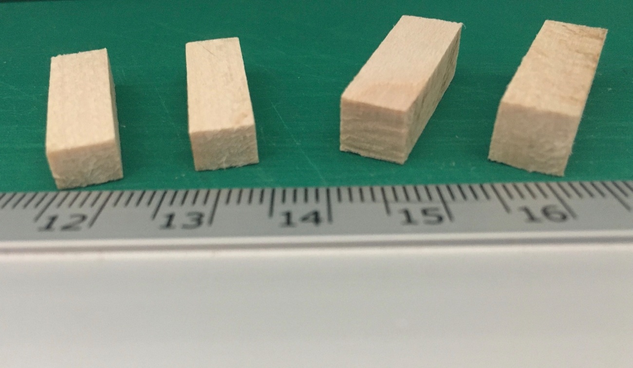
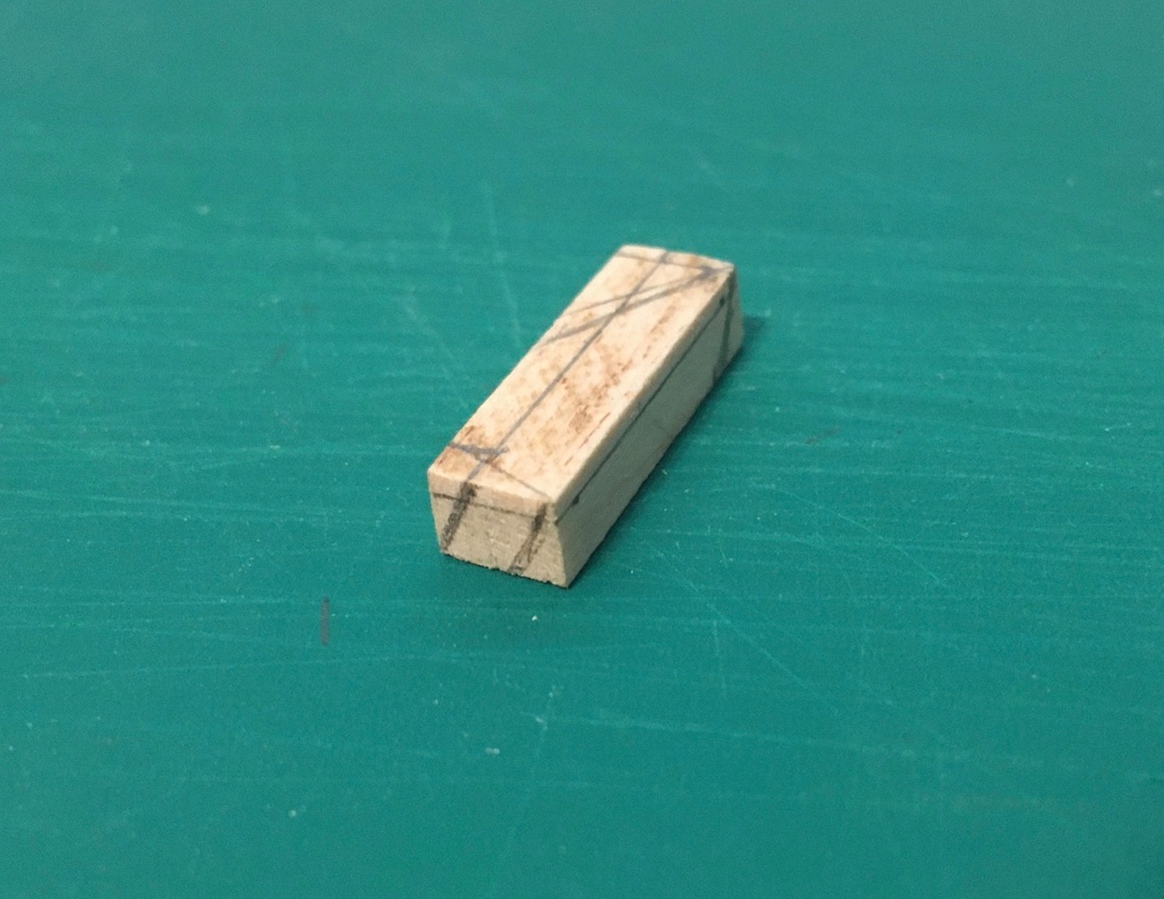
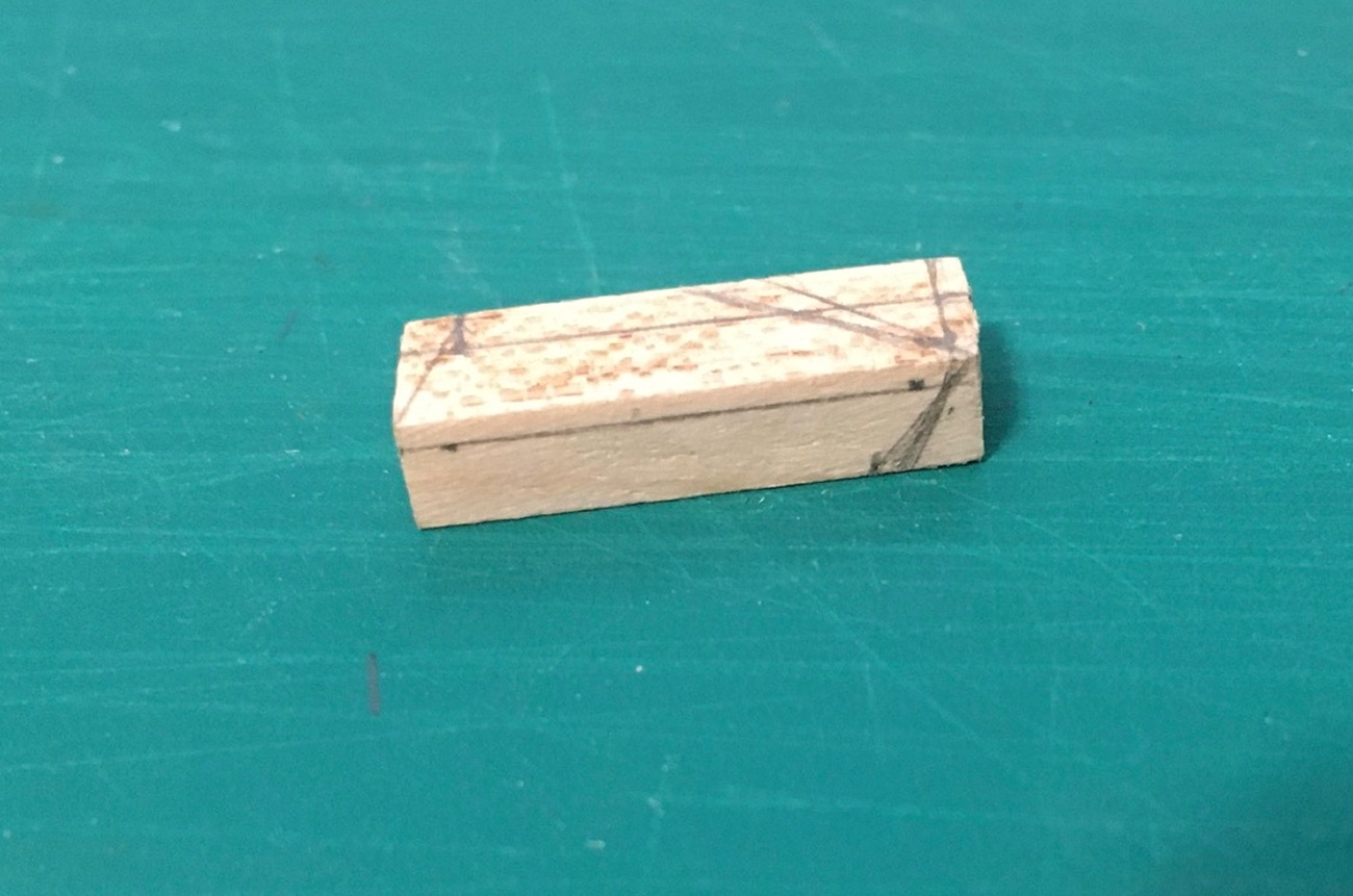
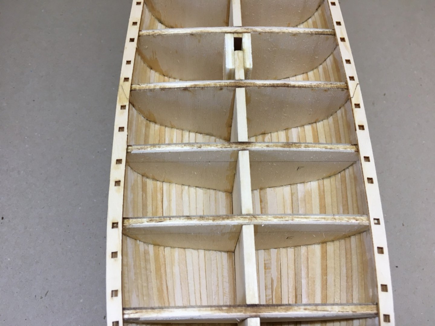
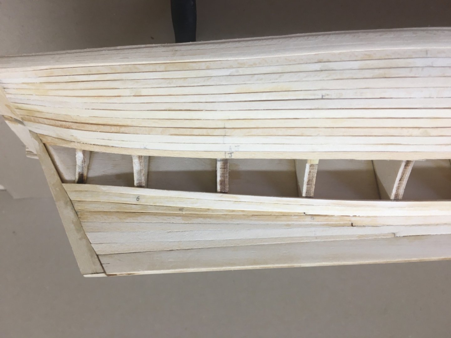
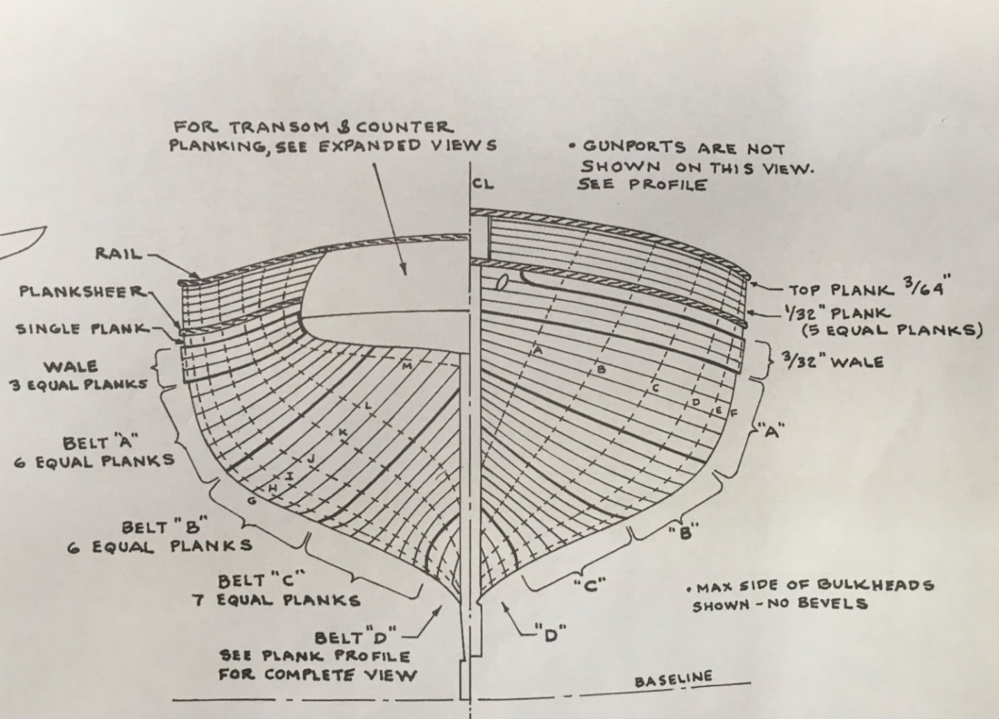
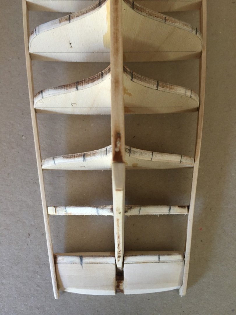
 So far I have followed the model's real building timeline with my posts. Here at the fourth month of the building I have to skip the timeline in order to maintain the logical subject integrity of this blog. At that time probably I was a bit fed up working with wood and did some work on flags, pennant and lettering of the ship which I plan to post later. After the manufacture and installation of stern knees, planksheers , transom planking and hawse timbers comes the planking of the deck. However before the planking of the deck you must make a choice about how you will handle the deck cabin and hatches and their coamings. You have two choices here. First one is to build and install the coamings , plank the deck around them and then build and install cabin and hatch trunks later . The second choice is to do the complete deck planking first and then manufacture and install the cabin and hatch trunks together with their coamings. The key point here is that the deck has a camber, meaning the height of the coamings at sides must be larger than their midline height especially in the larger ones like after cabin or main cabin (Please see the figure from the plan below ). To maintain this camber visually is critical and a must. I believe the best way to maintain the camber of the deck visually was to manufacture and install the coamings first and it indeed was how I handled the step. I thought it would be very hard if not impossible ( for me of course ) to ideally maintain the camber of the deck visually by sanding the coaming’s fore and aft side bases after the deck planking is done. By all means these are my thoughts and views only , and the final choice is of course the modeler's. So I started with taking measurements and locations from the plan. There are 6 cabins and hatches on the deck. With measurements taken from plans I drew the outlines of the coamings on 2 mm thick cardboard and cut them. Then on the model I marked the placements of the six coamings using those cardboards. The height of the wood used to manufacture the coamings is 1/8 inches (3.2 mm) and thickness is 3/32 inches (2.4 mm). I cut strips of 3-3.5 mm from a 2.5 mm thick pine wood piece. Then using the reference cardboard pieces I cut the strips for each one. Although the coamings will be painted later, I tried to manufacture them in true manner and cut the corners diagonally at 45 degrees and started gluing them by using a jig to ensure their square structure. The upper edges were chamfered and their locations on the model were checked. As the deck planking will be directly on the bulkhead tops and no false deck use was planned, I thought it would be a good idea to build and place some wood blocks to the spaces between bulkheads, starting from the bow and all the way back to the stern, where coamings will be placed in order to support them and also the adjacent deck planks. In the picture below i is port and s is starboard (iskele : port and sancak:starboard turkish terms ) Numbers indicate the spaces between bulkheads starting from bow (1) and up to stern (10). The support pieces were dry fitted and checked with the coamings. Then the support pieces were sanded. Then I glued the coamings to their places. The spaces at sides in the largest coaming, after cabin) were supported from inside with wood strips. And also at corners from outside . Here at the end of post #24 I once more apologize for language mistakes , from native English speakers.
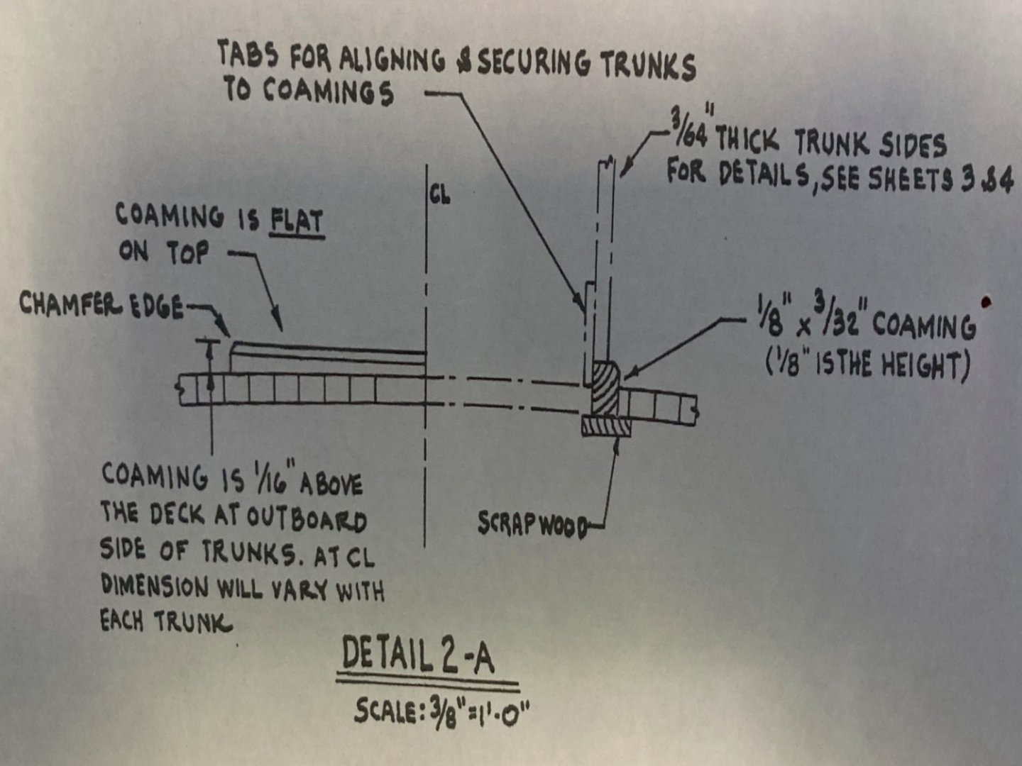


- 114 replies
-
- 2
-

-
- Pride of Baltimore II
- Model Shipways
- (and 1 more)
-
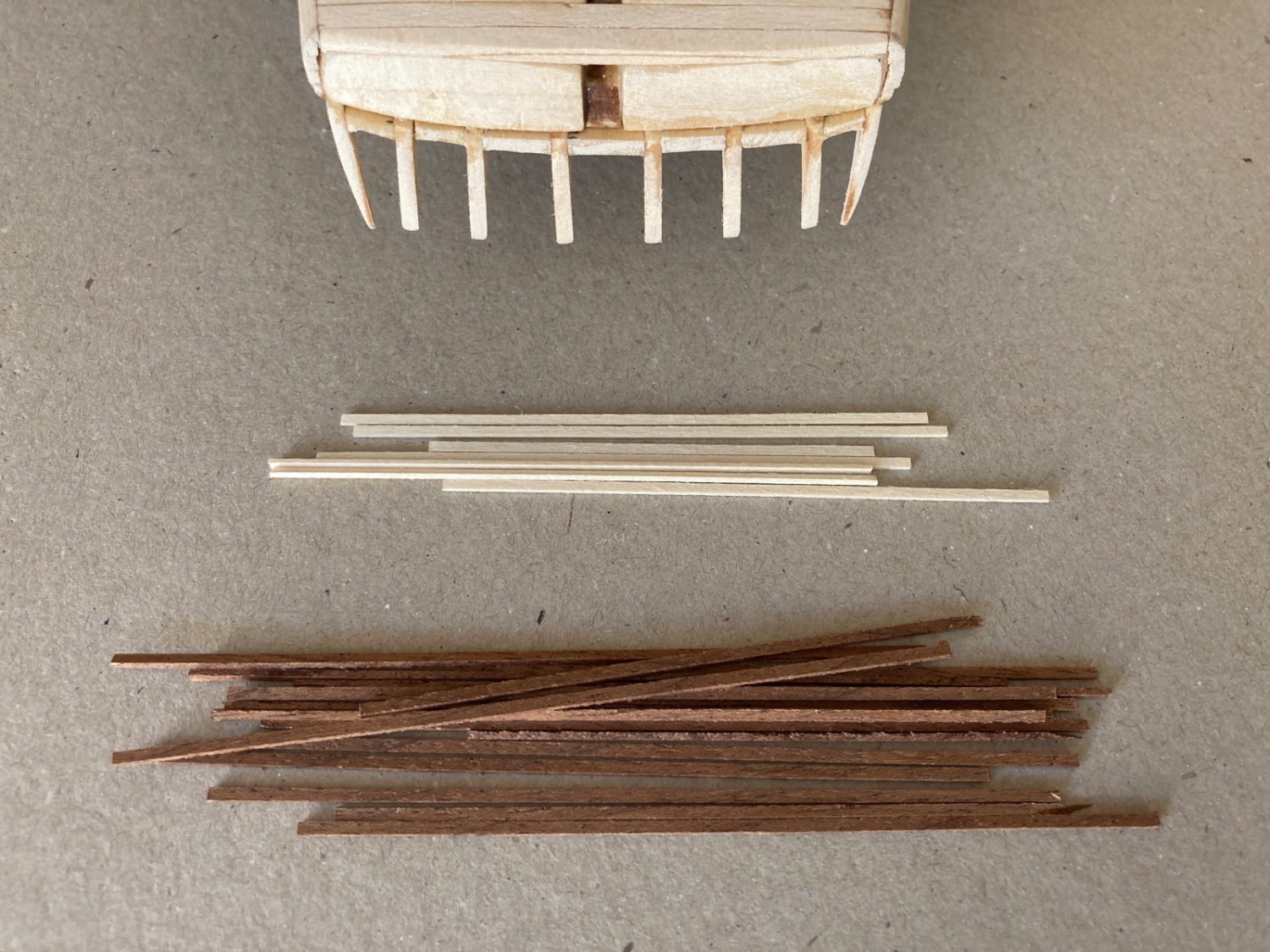
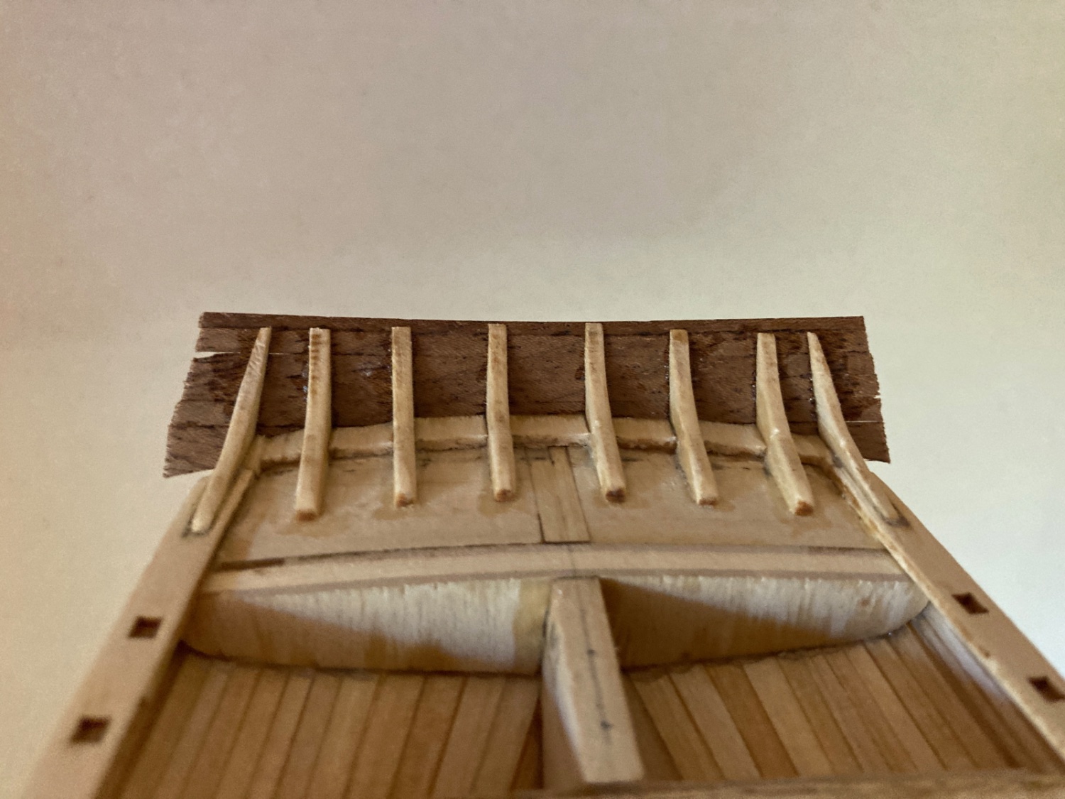
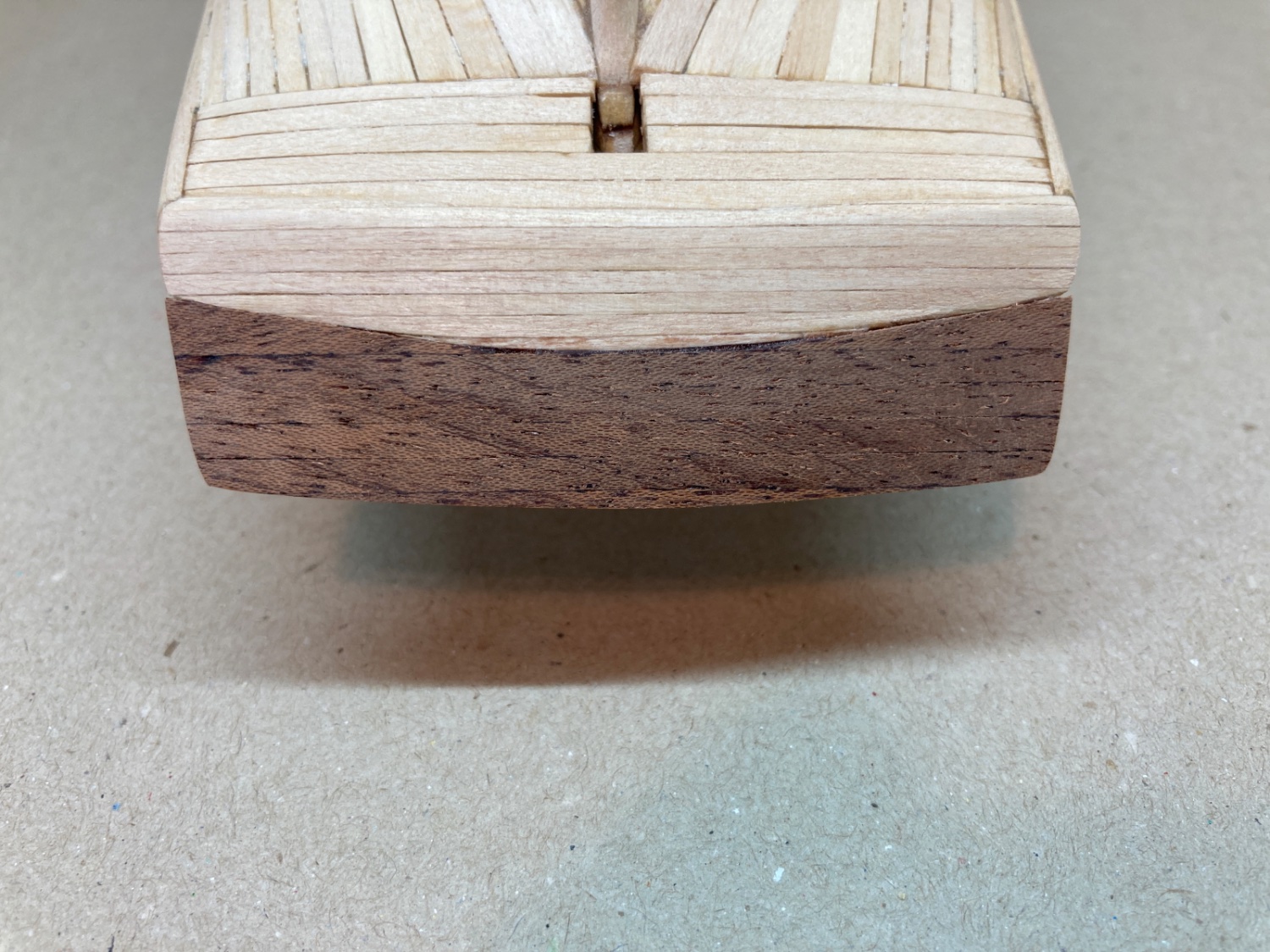
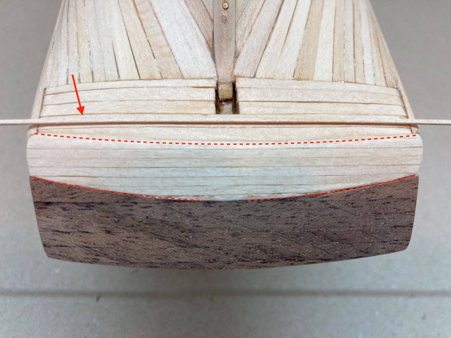
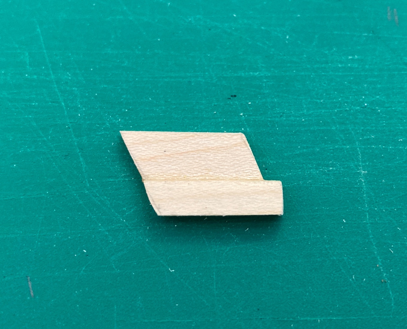
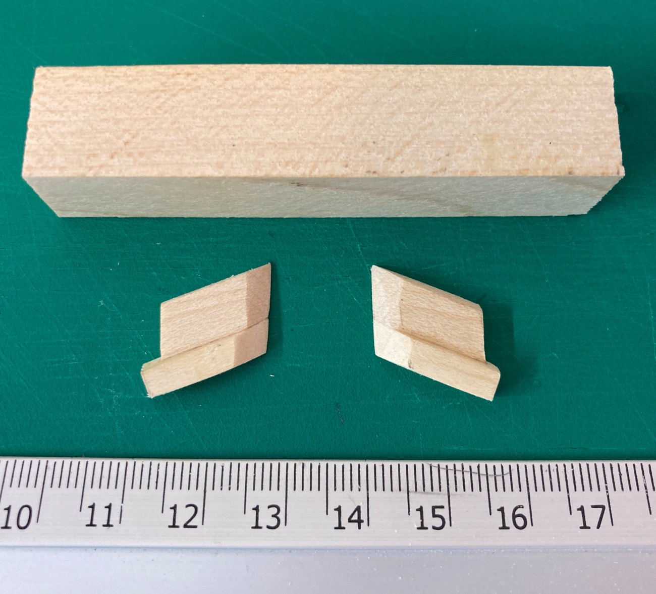
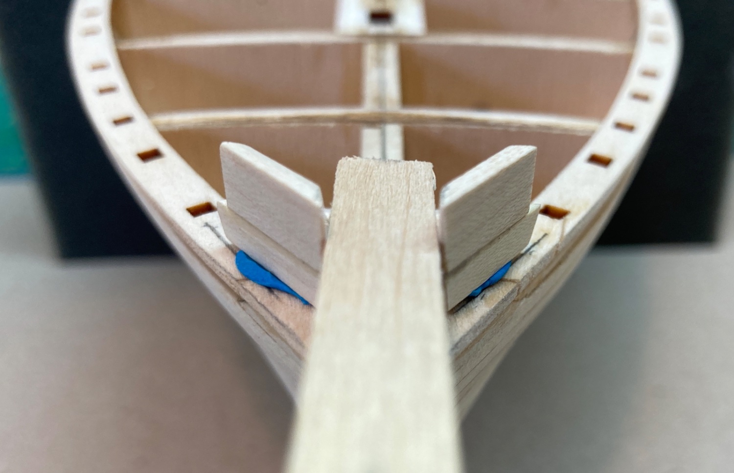
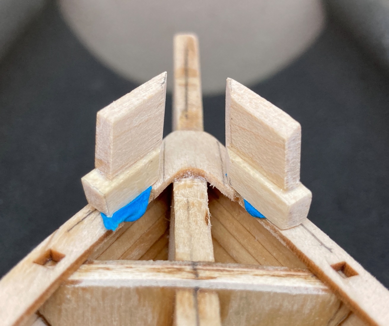
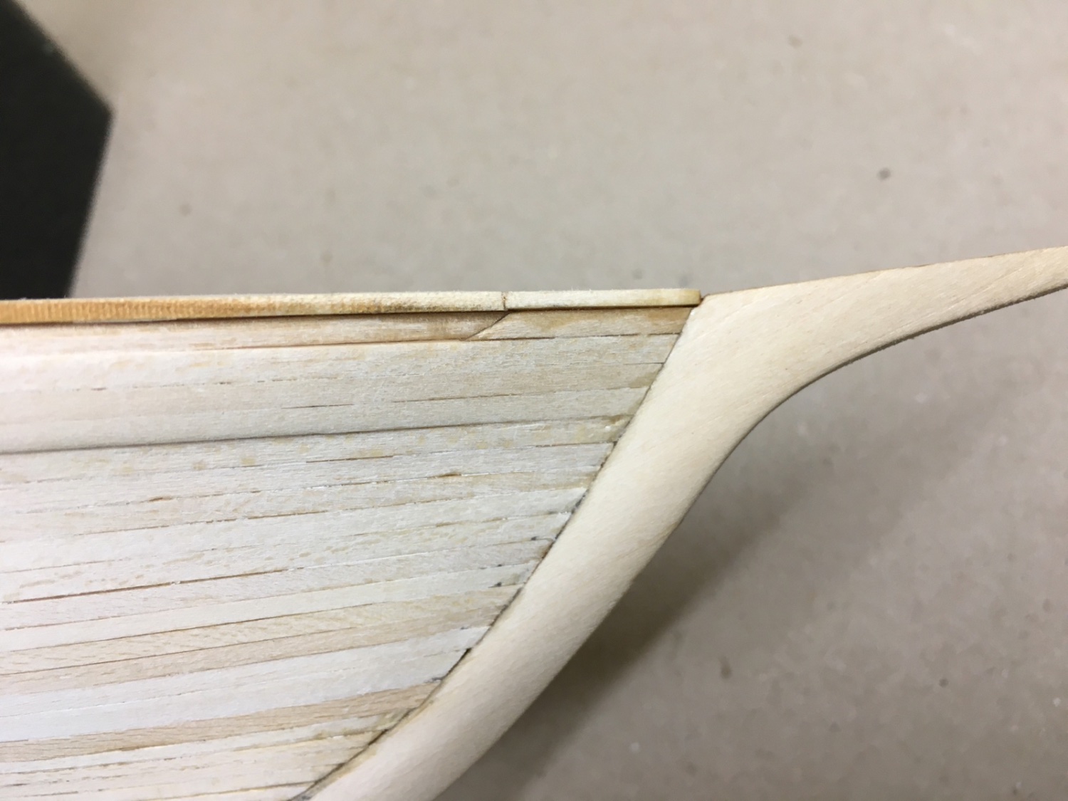
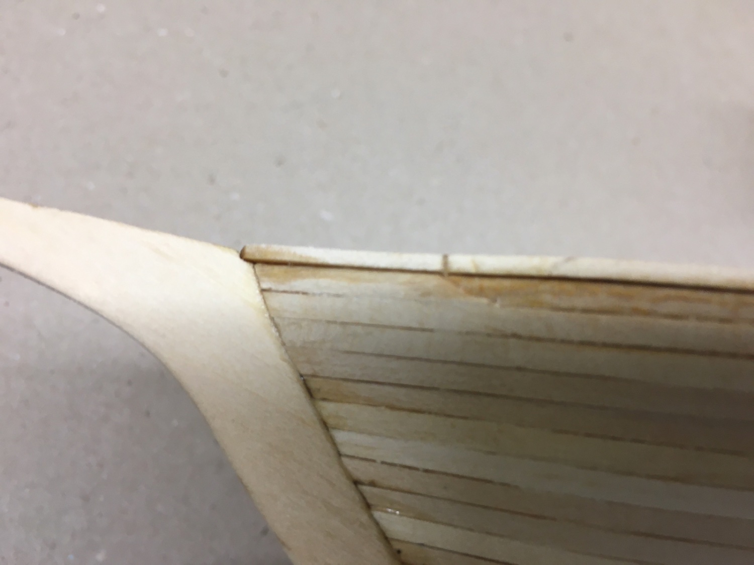
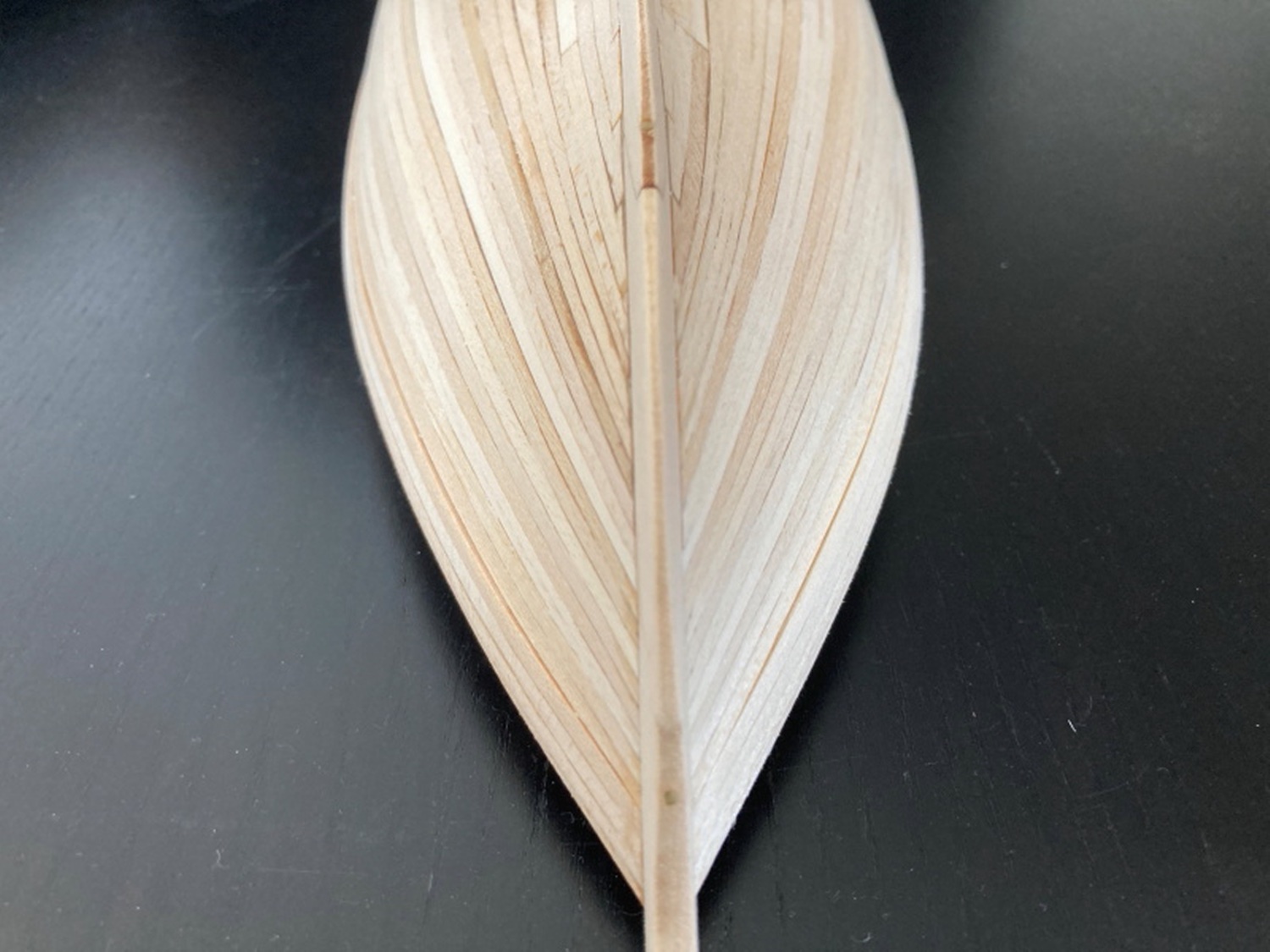
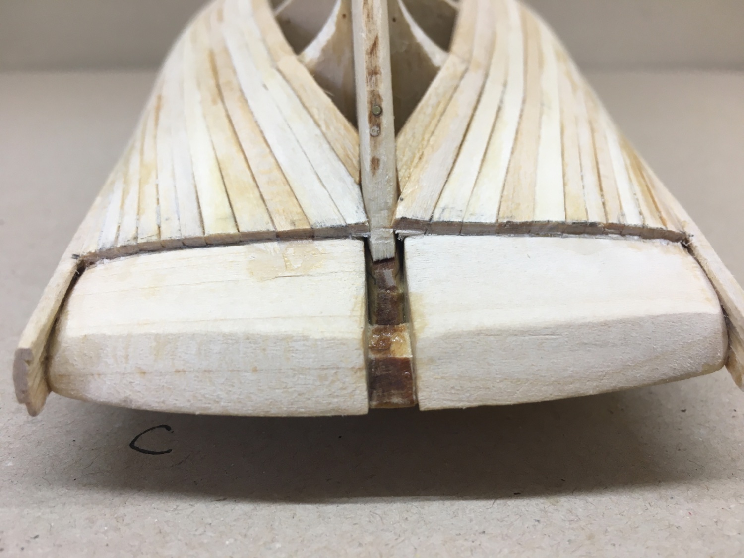
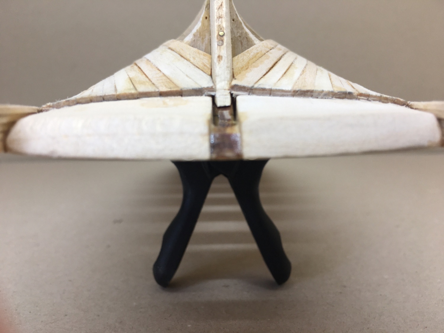
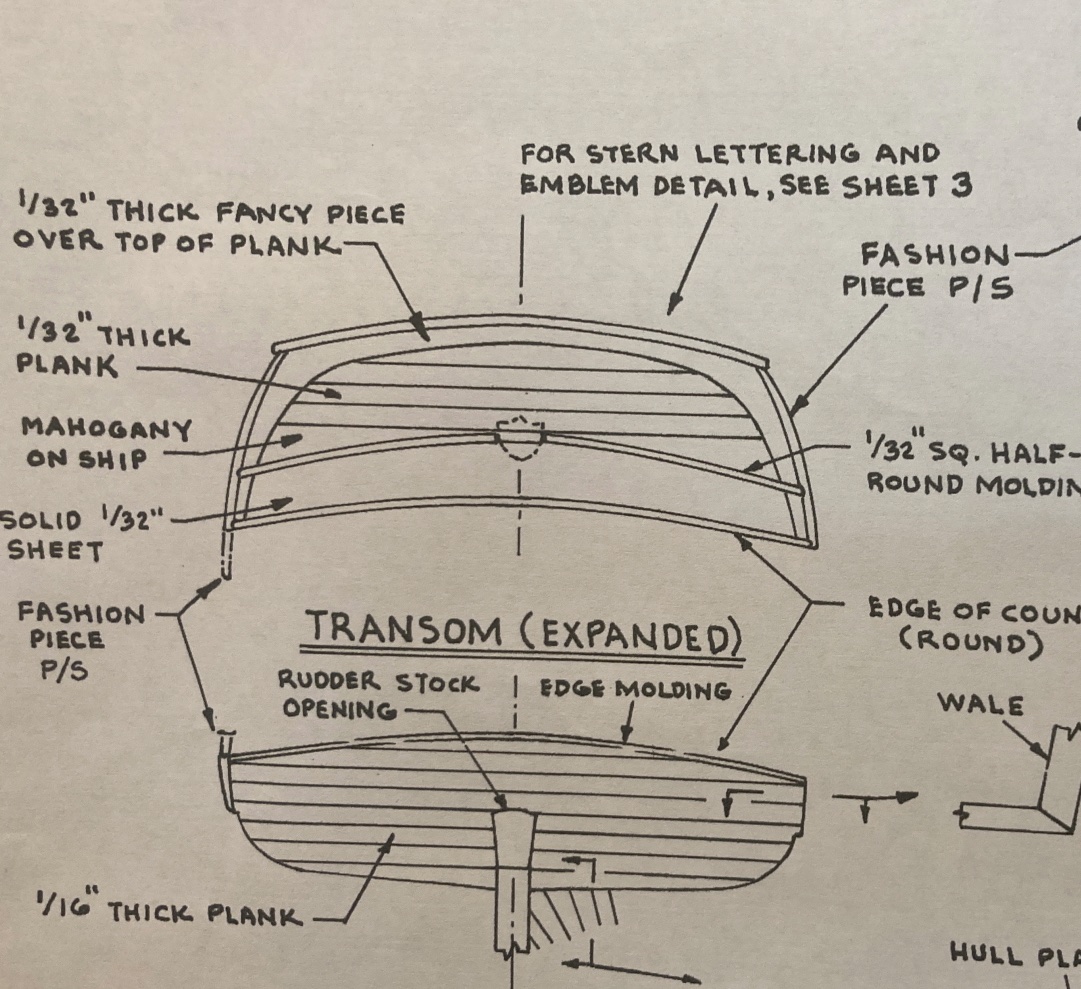
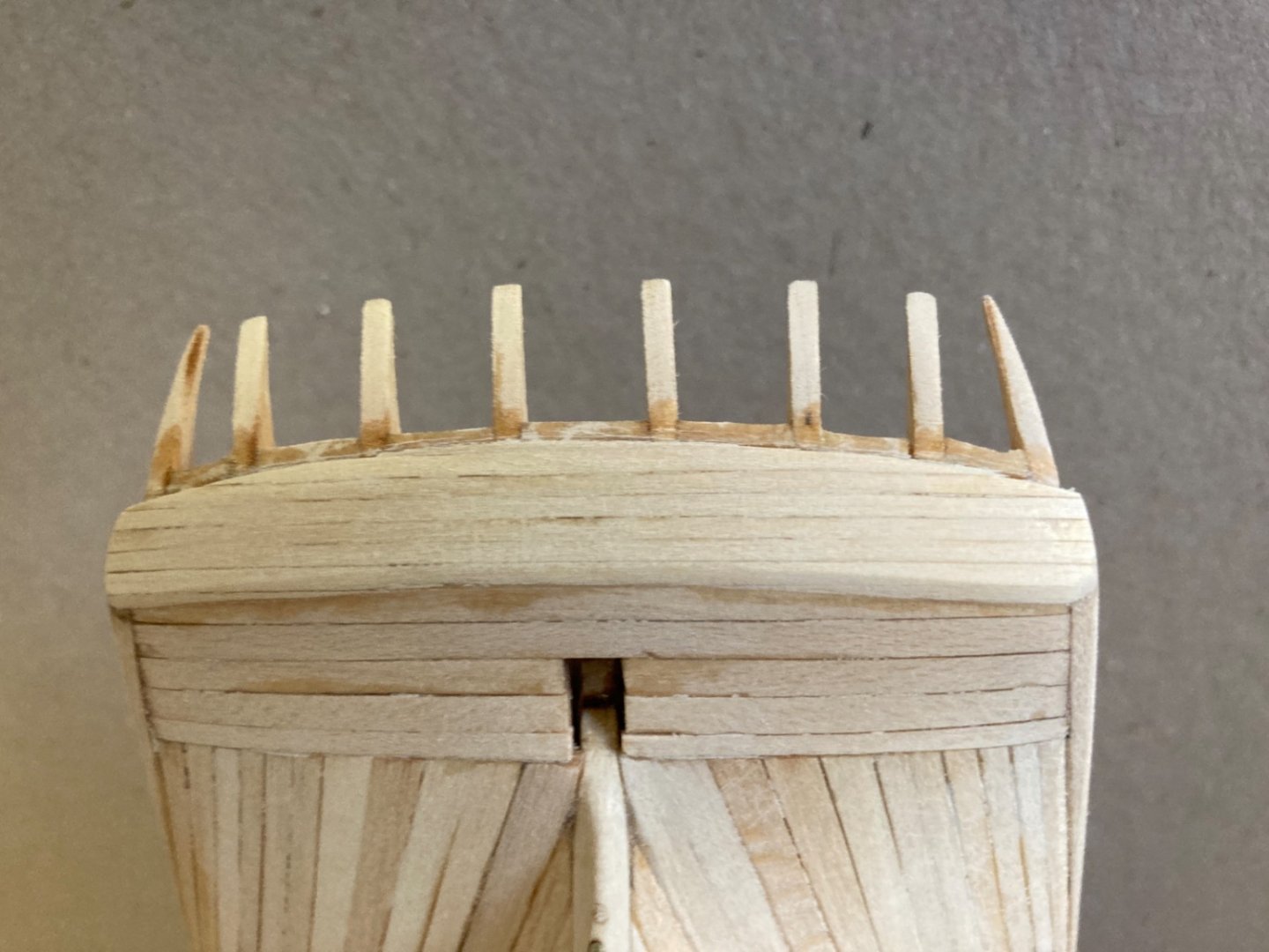
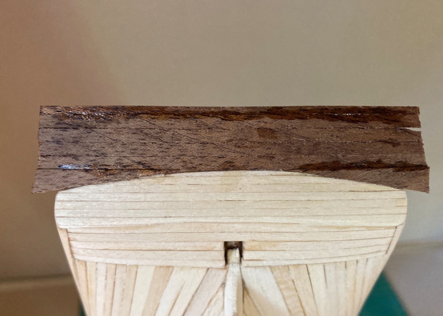
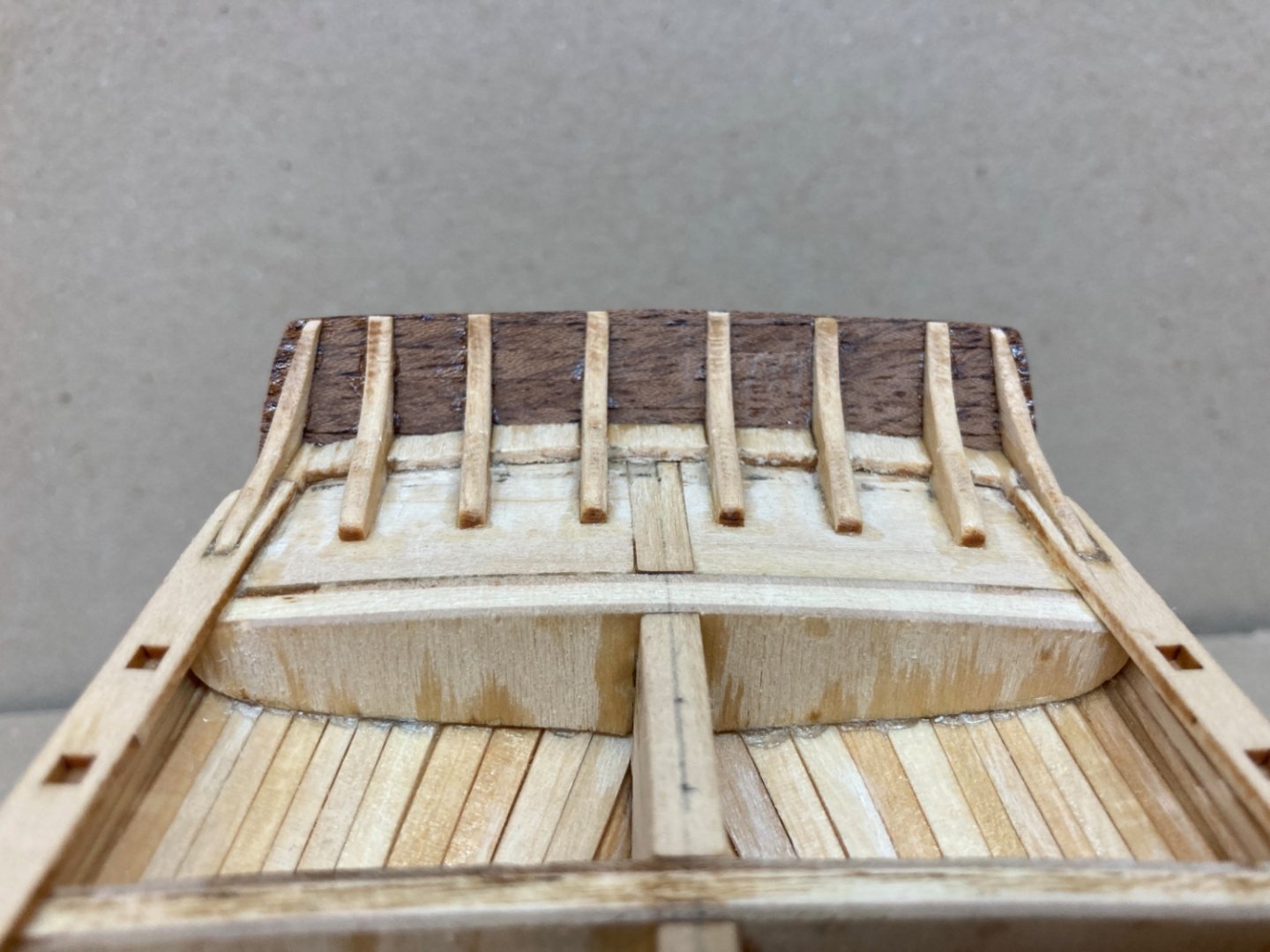
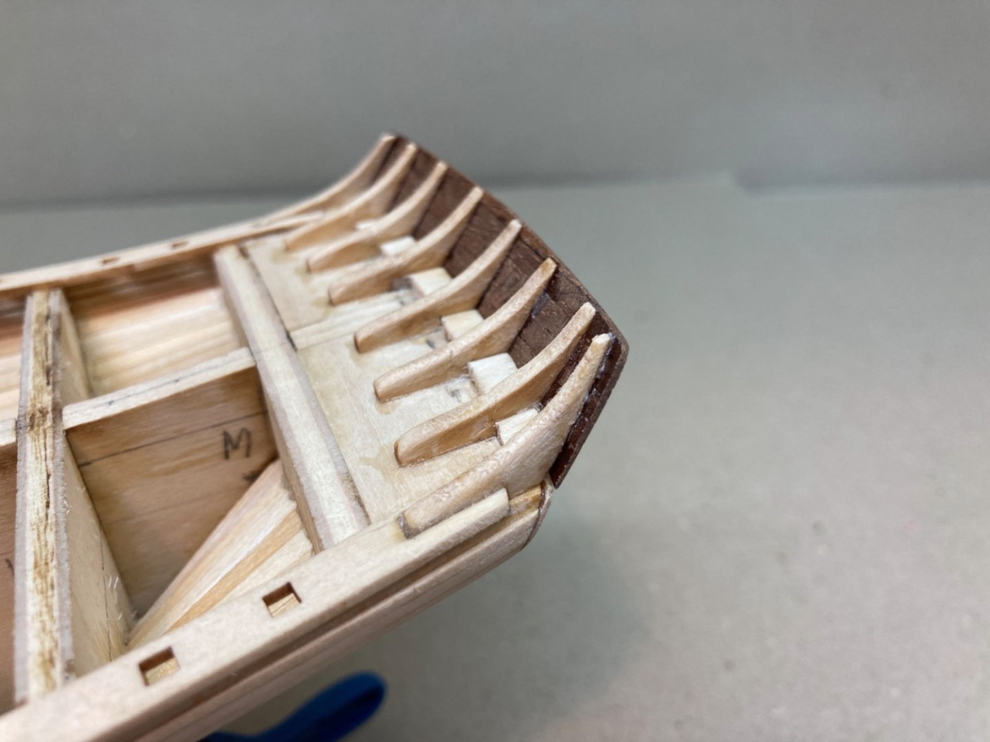
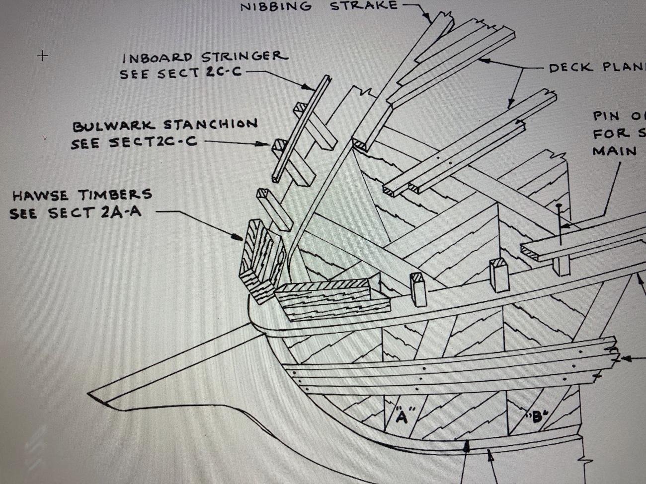
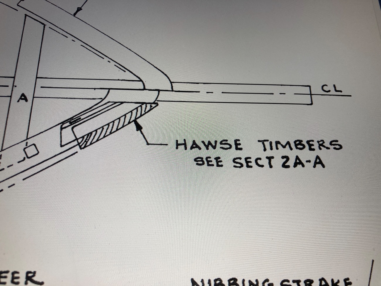
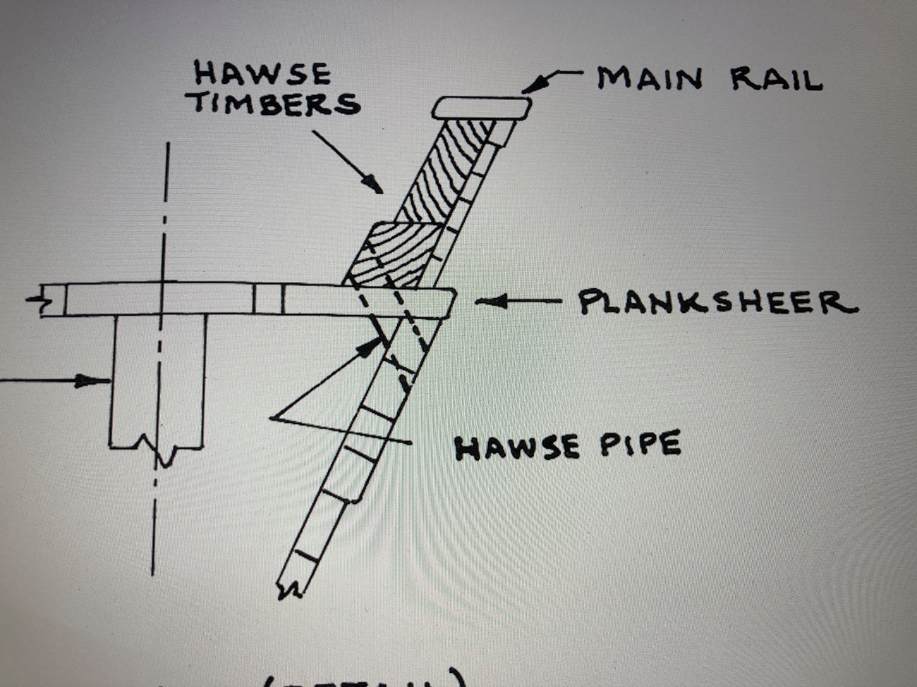
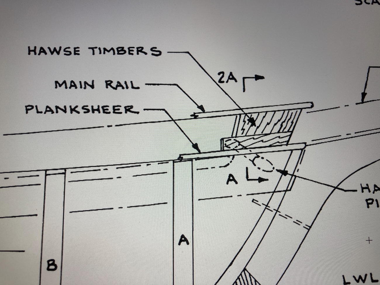
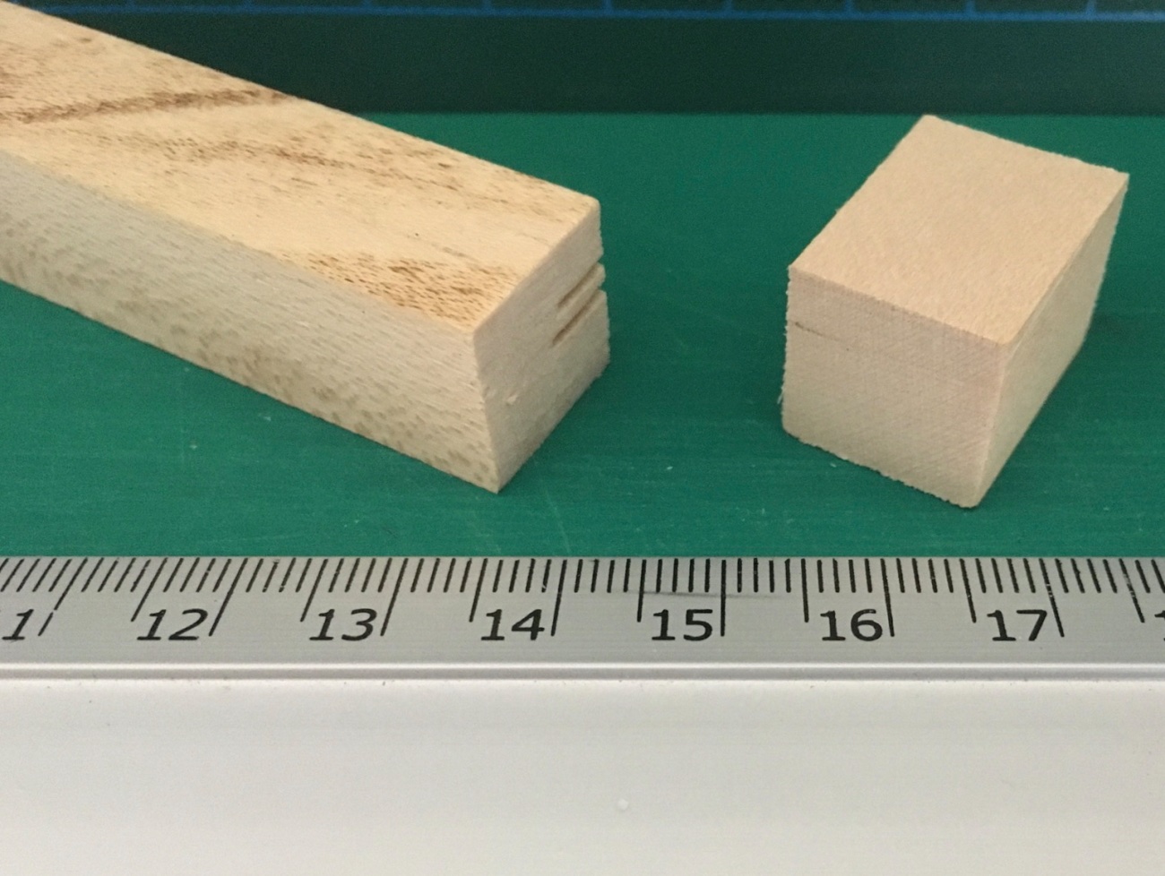
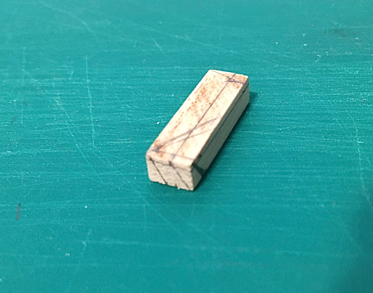
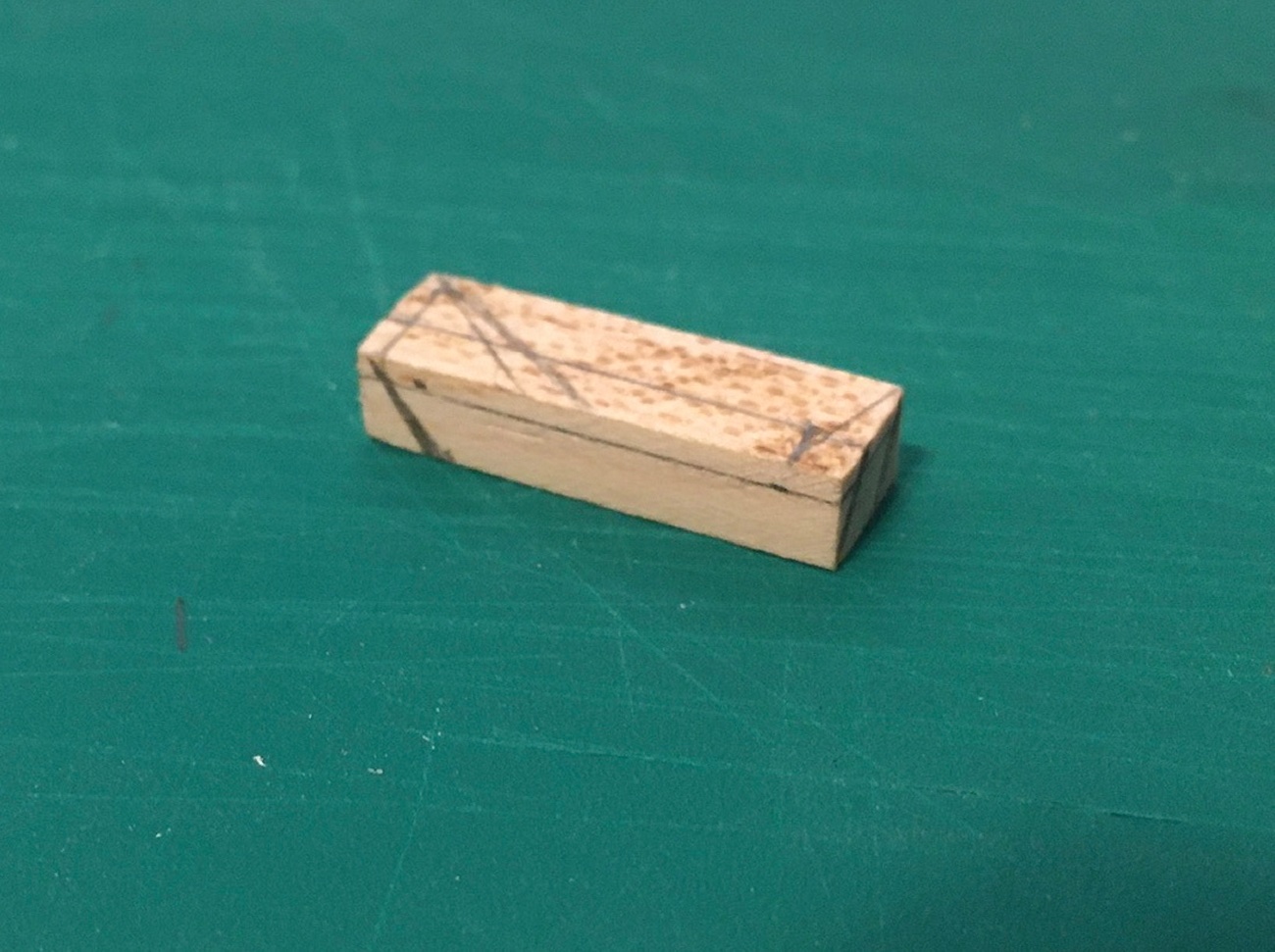
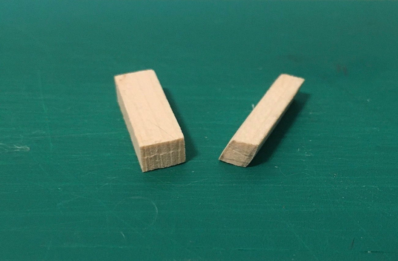
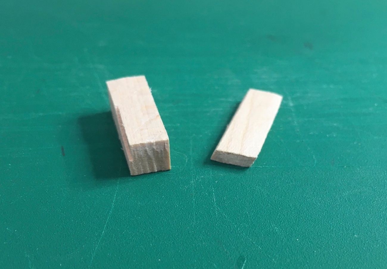
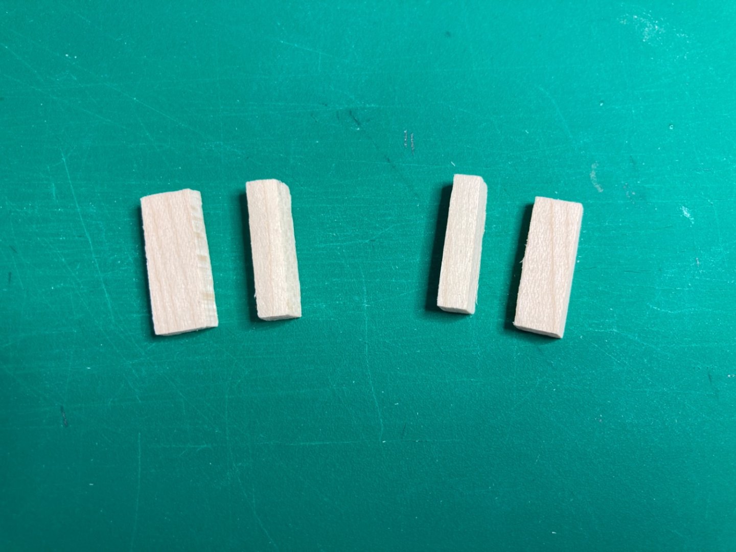
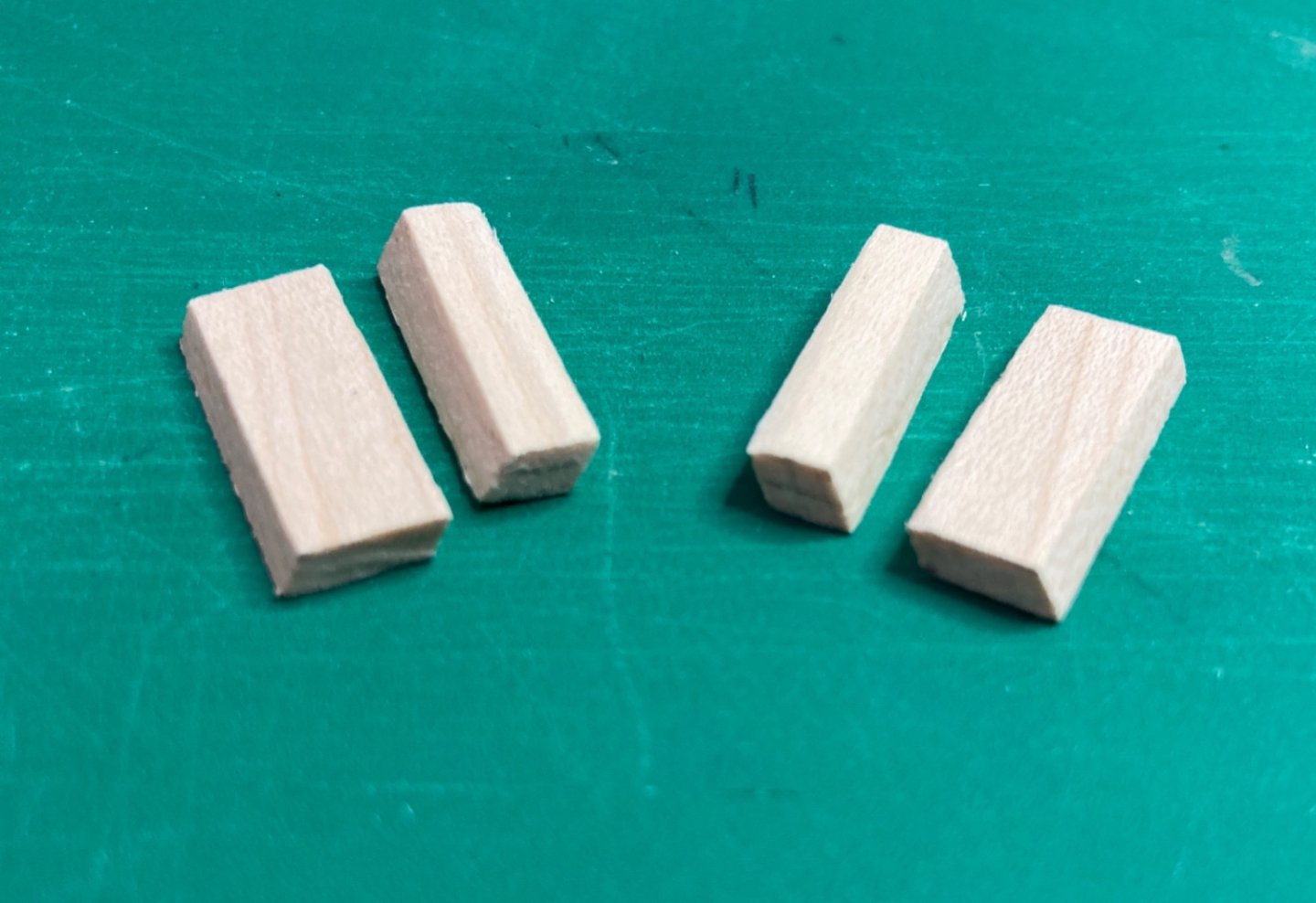
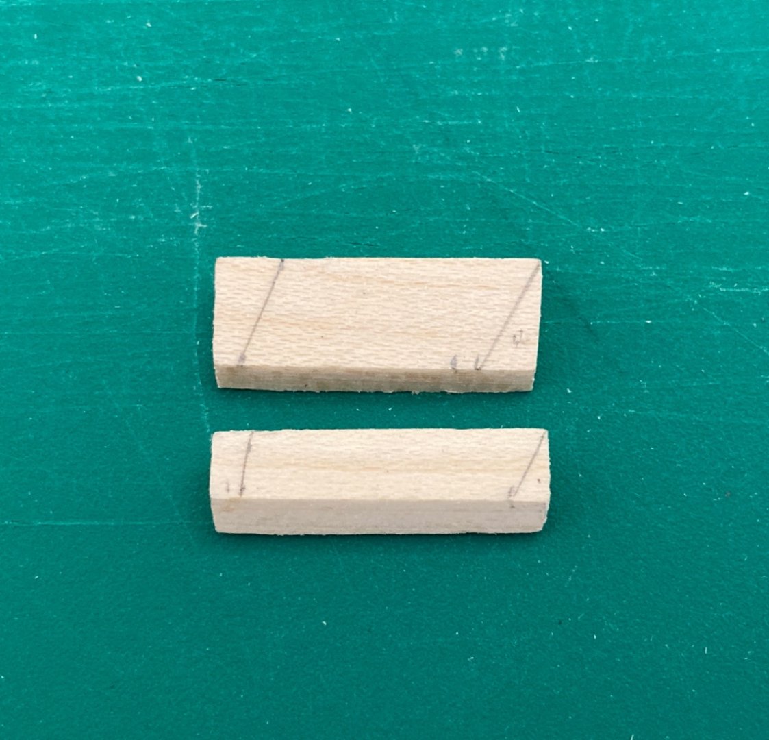
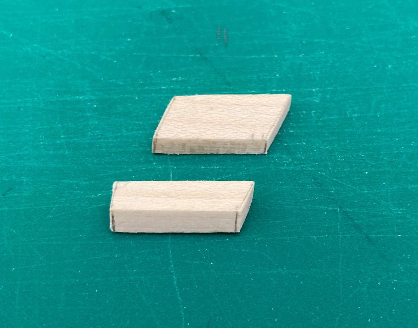
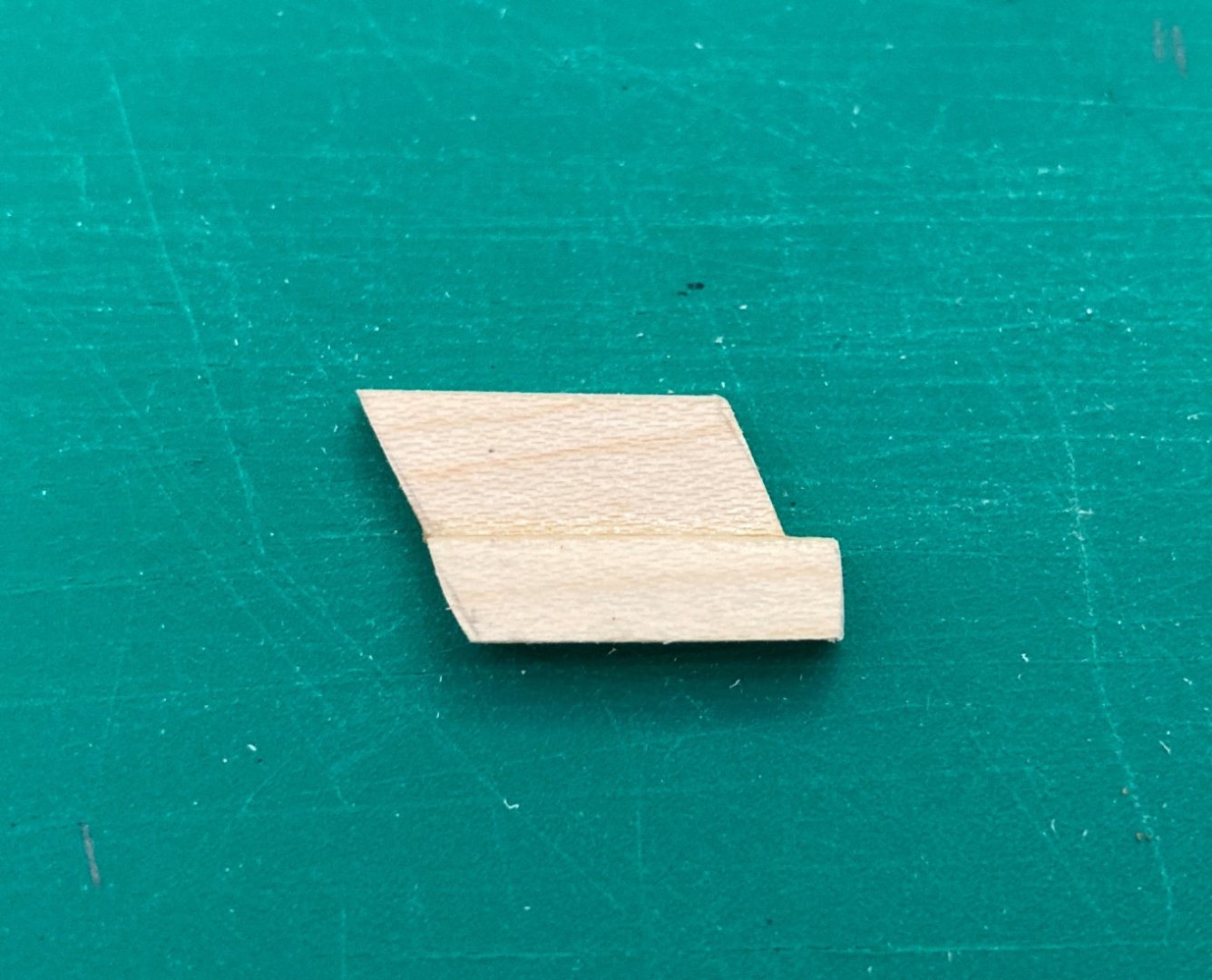
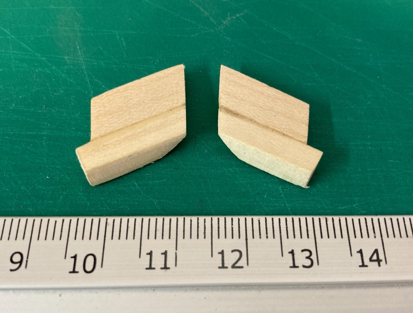
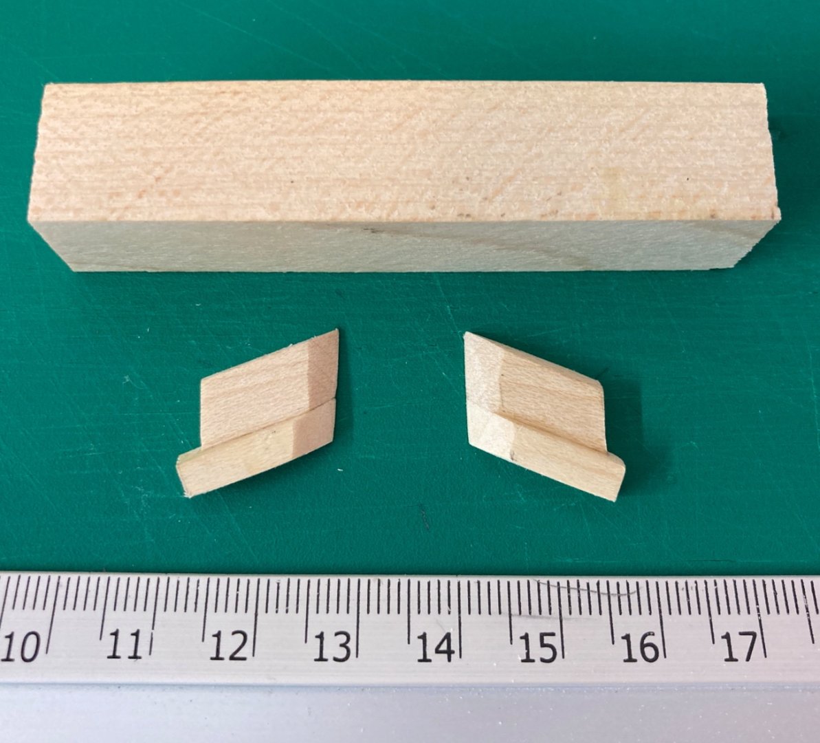
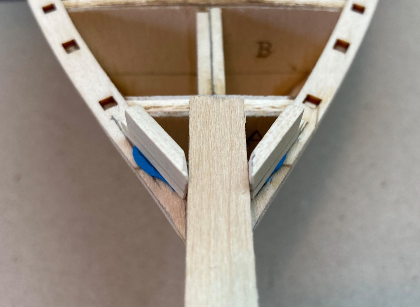
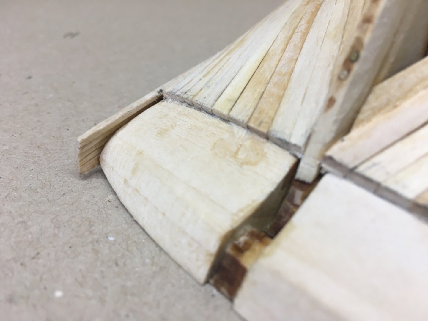
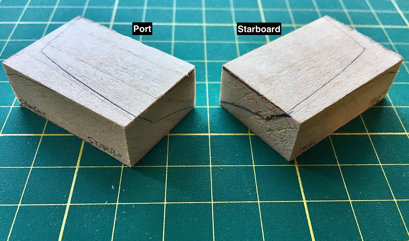
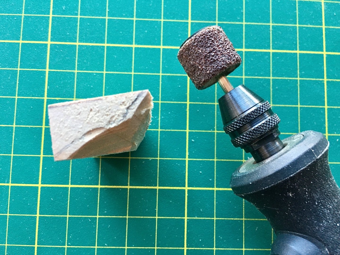
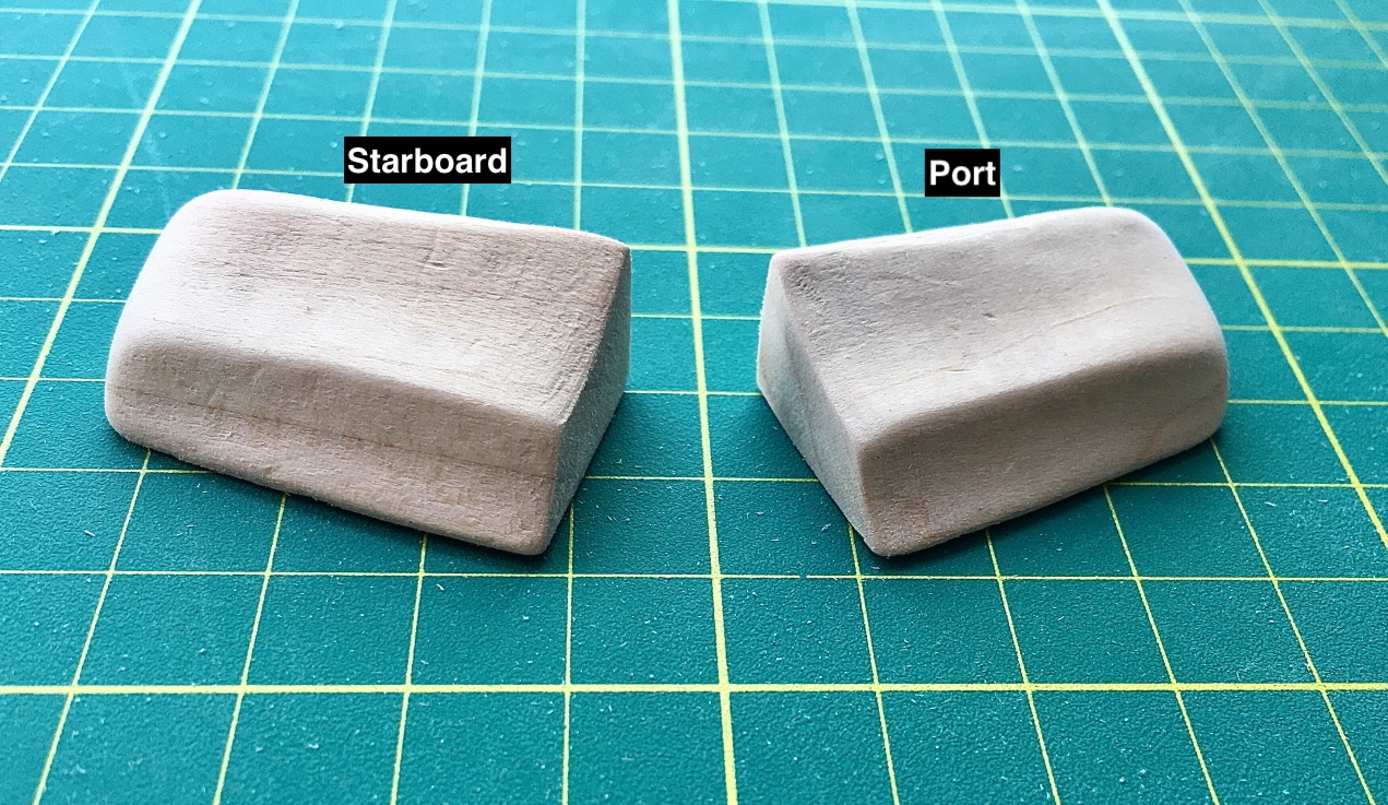
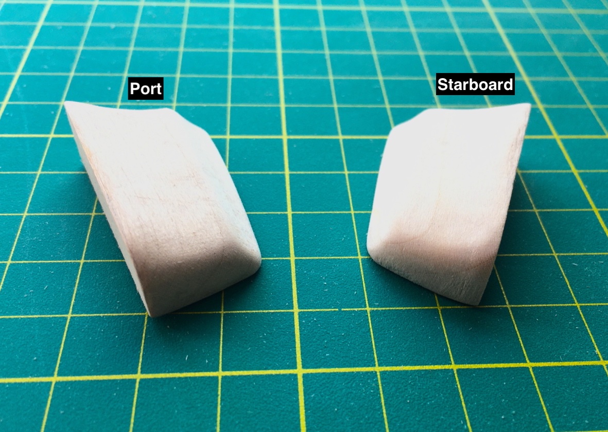
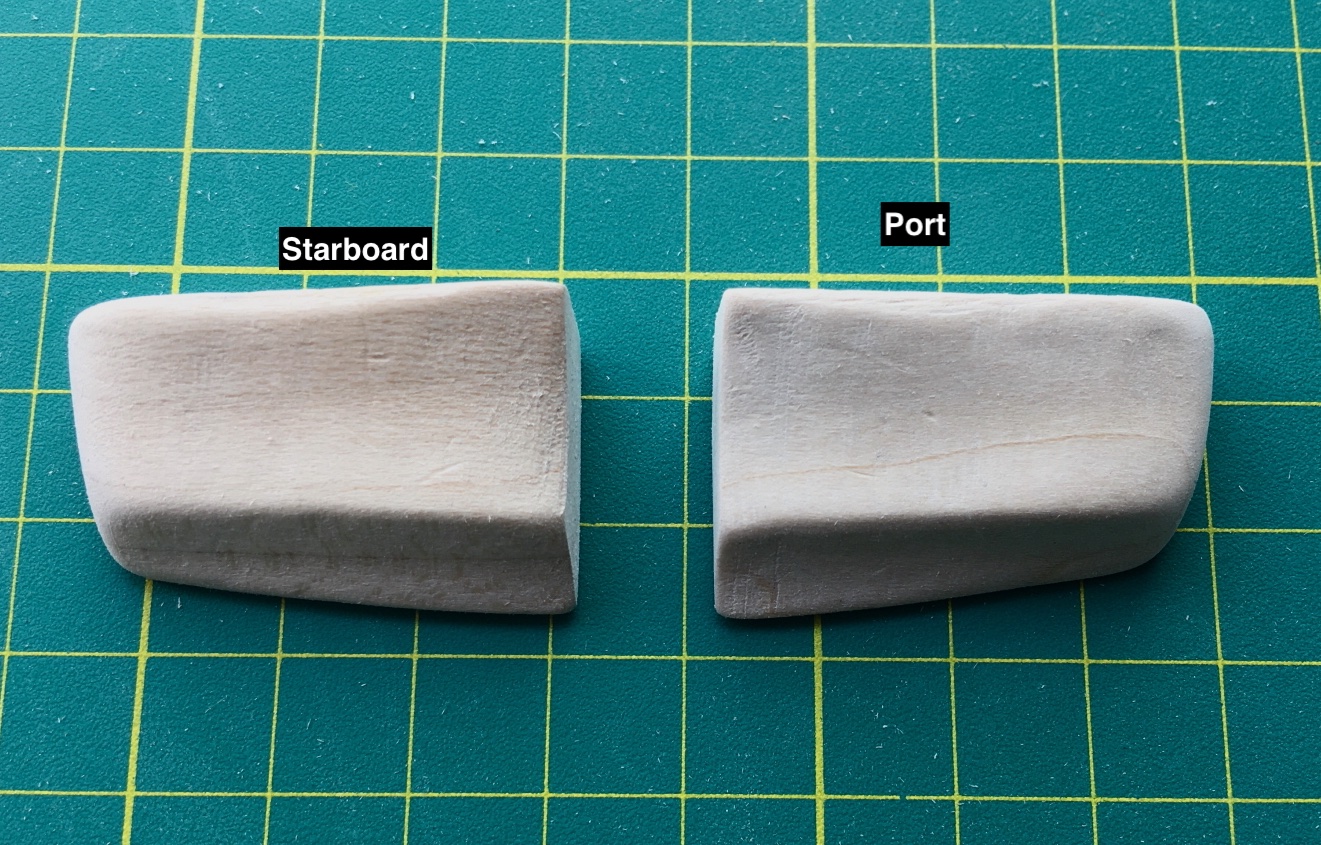
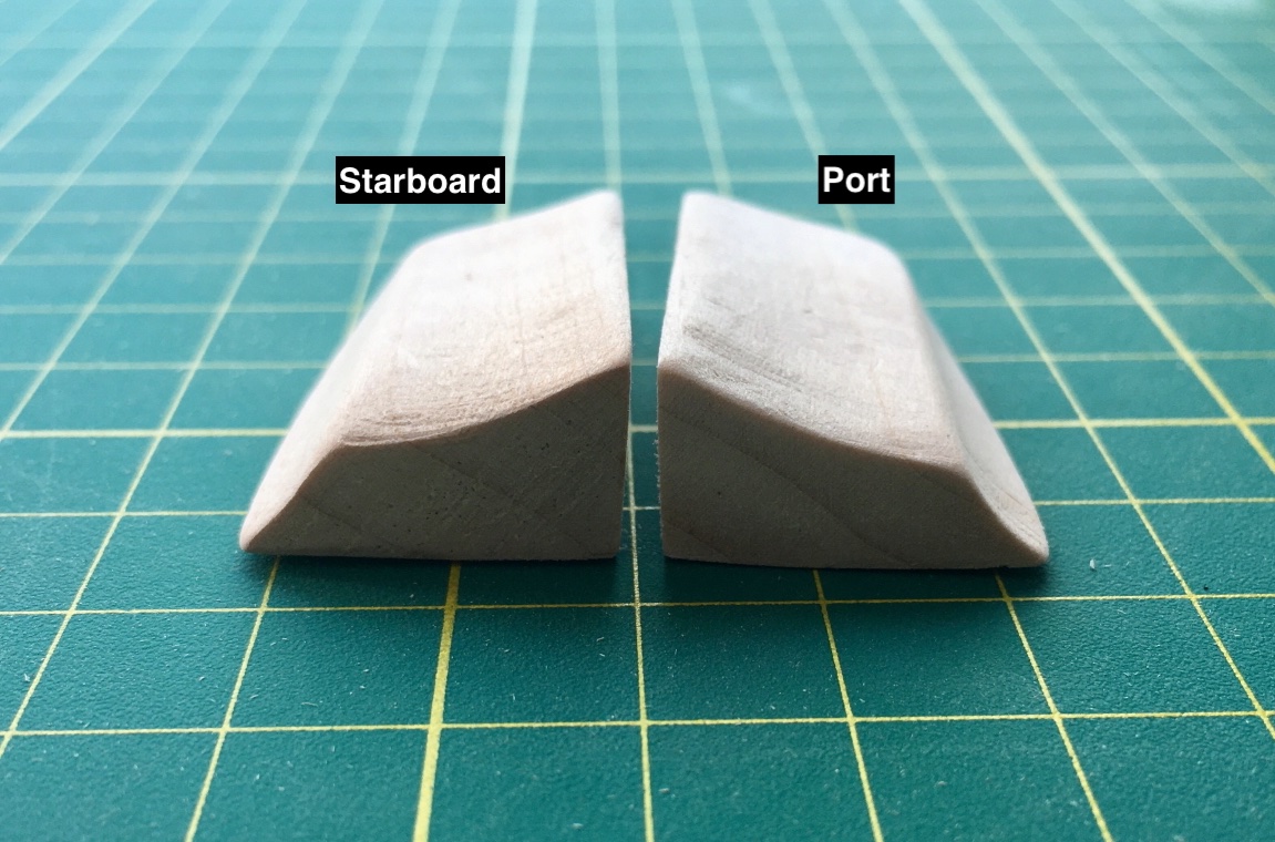
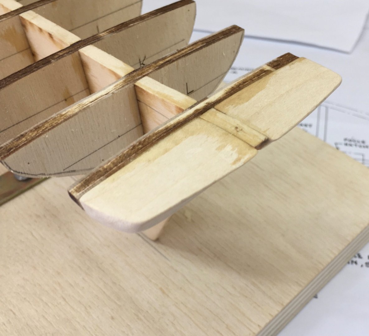
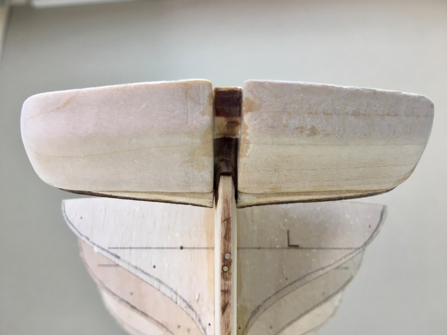
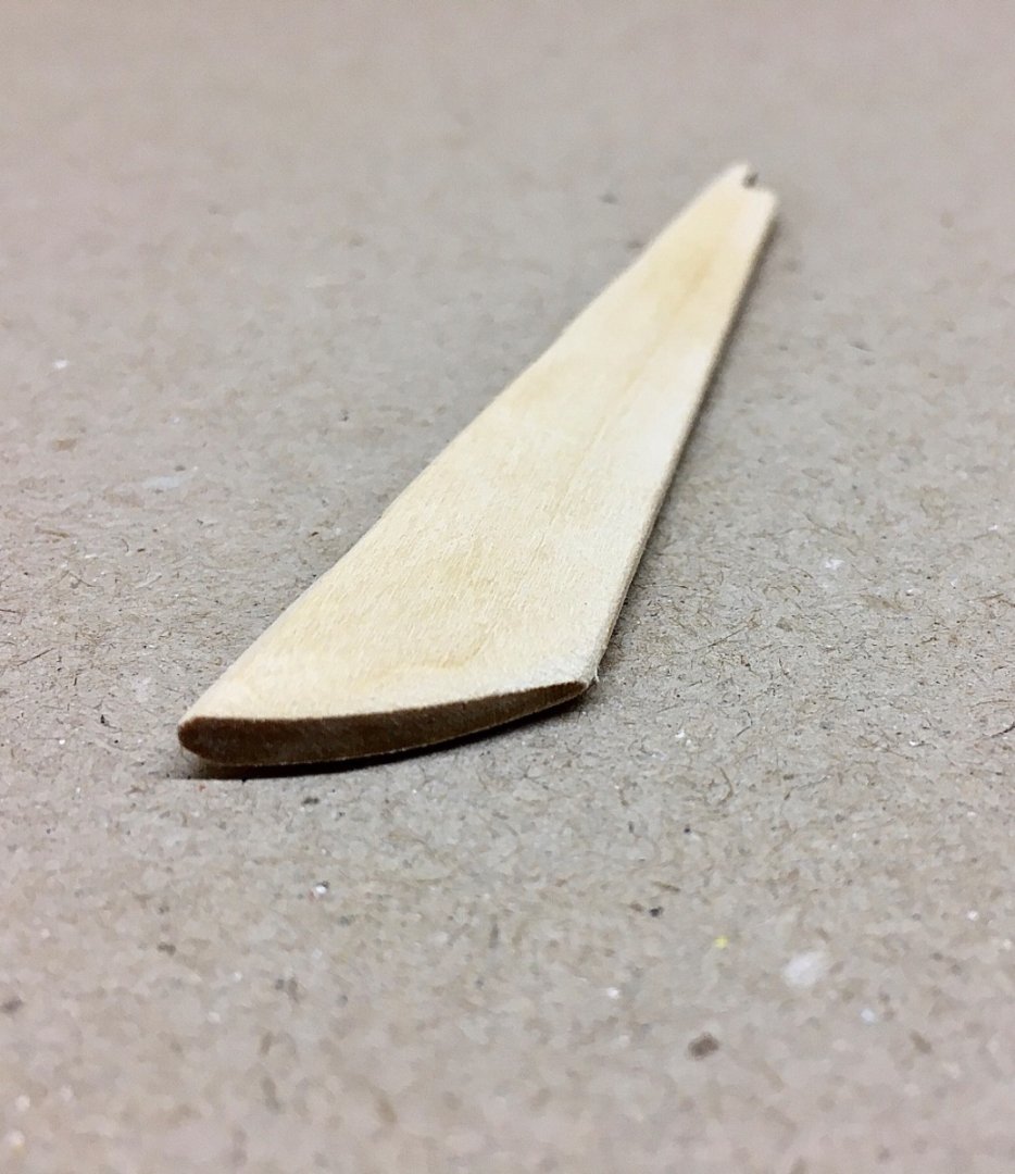
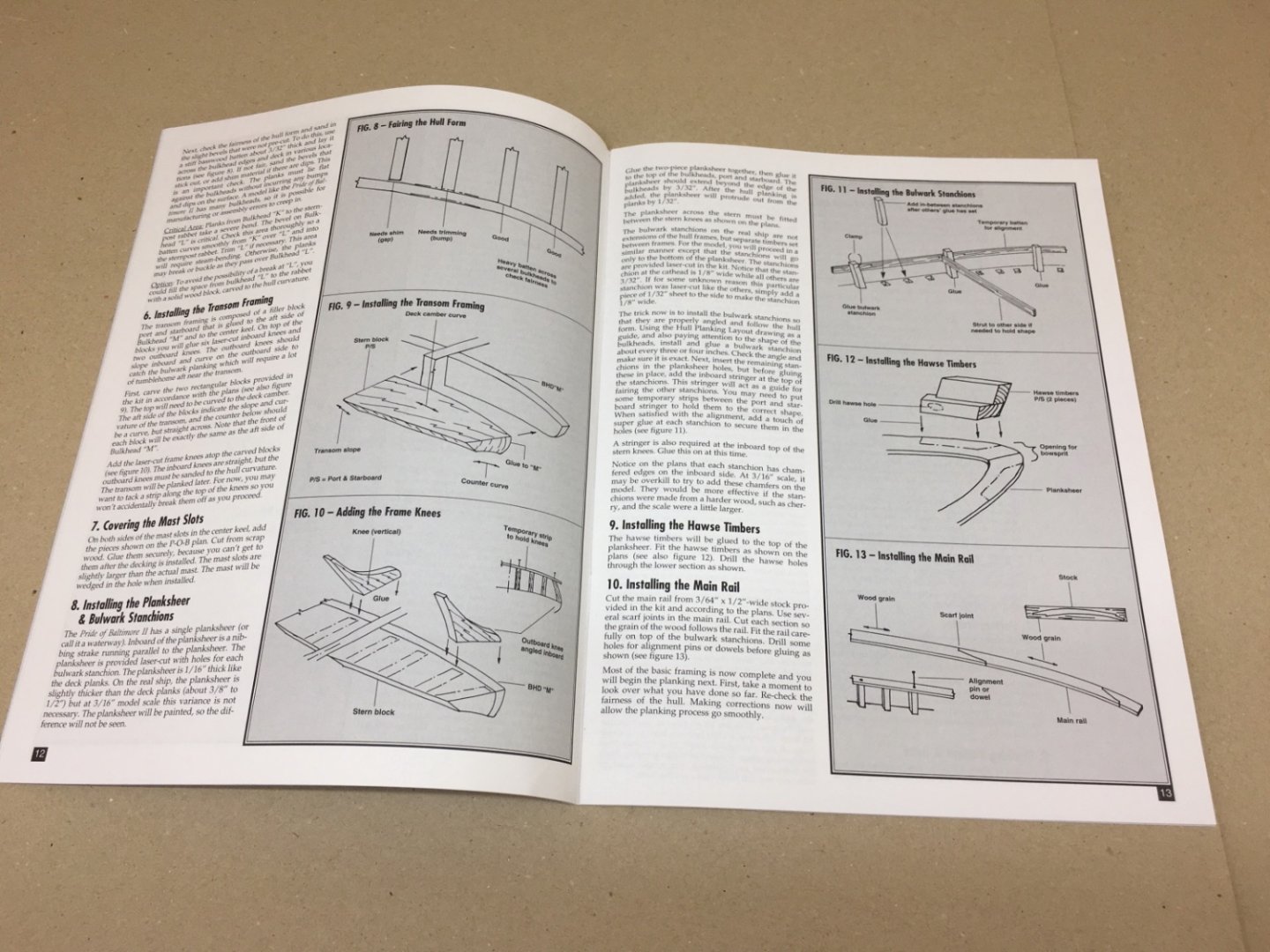
The next job was transom planking. Here the transom is composed of two parts as seen in the picture from the plan . Below is the part created by the aft face of counter filler blocks and at above the aft face of stern knees which will be planked. The kit instructions dictate the lower part as one piece block 1/32 inch (0.8 mm) although the kit designer thinks that it was probably composed of planks. The part above is mahogany and composed of planks also with 1/32 inch (0.8 mm) thickness. The lower part is painted later (yellow) and the basswood 1/32 stock from the kit, reserved bulwark planking, is used. For the upper part I cut out strips from mahogany sheet I already have but having to do a lot sanding in order to reduce it’s thickness from 1.5 mm to o,8 mm. Before the installment of these planks I should point out an important step I forgot to mention in my previous post. The aft faces of the stern knees must be flush and on the same plane with the face of the lower transom created by the aft face of the counter filler block. I started with the lower transom. After sanding Upper transom mahogany planking After sanding Probably It would be better to sand both above and lower transom planking to achieve a better border between them. However as a thin (0.8 mm 1/32 inch) strip (red dotted line showing placement of the thin strips seen below) will be placed there later , I moved on Then comes a tricky structure placed at the bow on both sides. Hawse timbers are sturdy structures and the most fore part of bulwarks. There are hawse pipes passing through the holes in them through which chains (port) and ropes (starboard) for anchors pass. Hawse timbers consist of two parts. I decided to use hard wood (which I do not remember the type now) in order to cut and sand without the fear of wood disintegration. There are several figures on the plans. Hawse timbers have two parts. Suitable size starting woods are cut from the stock. The borders are transferred from the plans after measurements and first the lower parts were cut . Their fore faces are cut diagonally after dry fitting on the model and using wood which later be used for preparation of bowsprit.


- 114 replies
-
- 2
-
-
- Pride of Baltimore II
- Model Shipways
- (and 1 more)
-
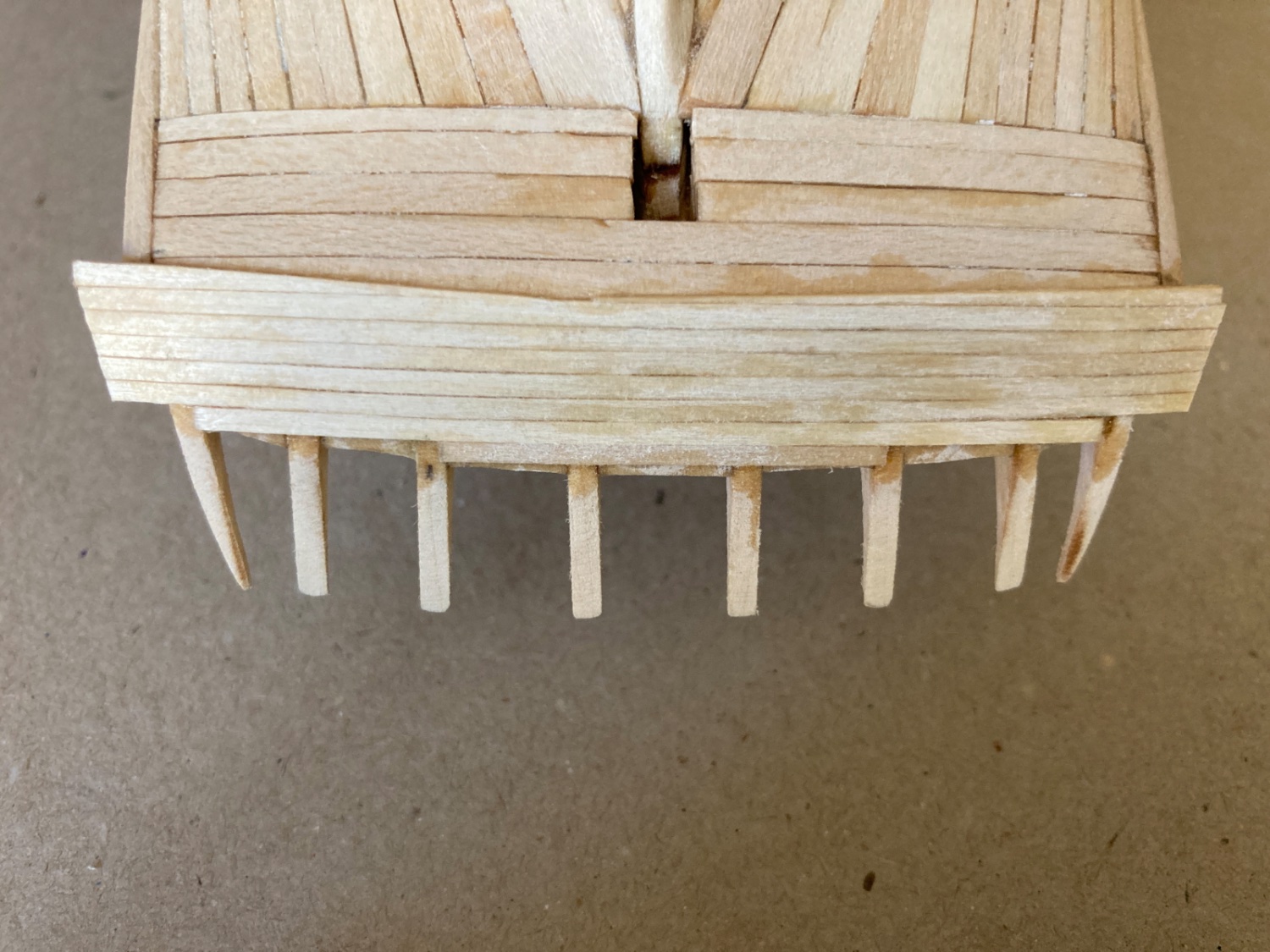
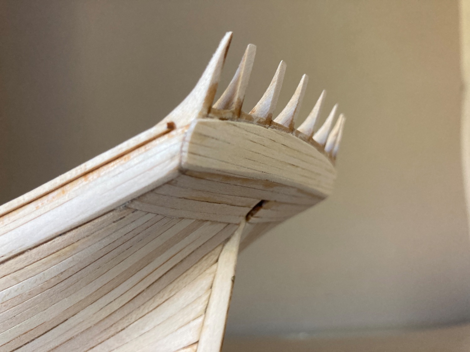
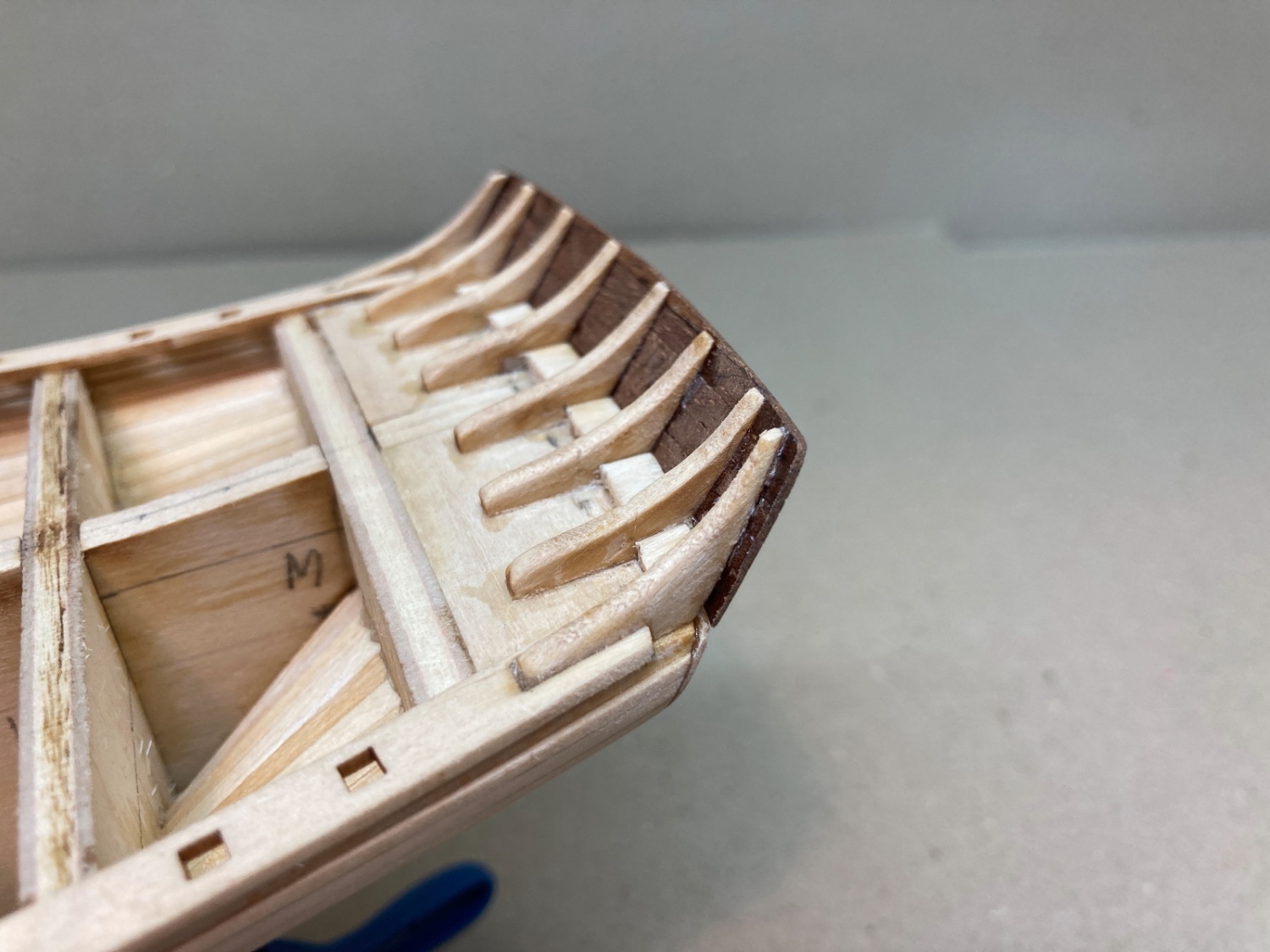
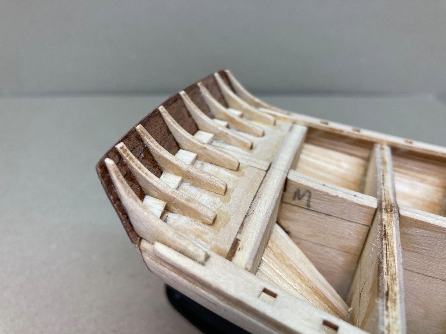
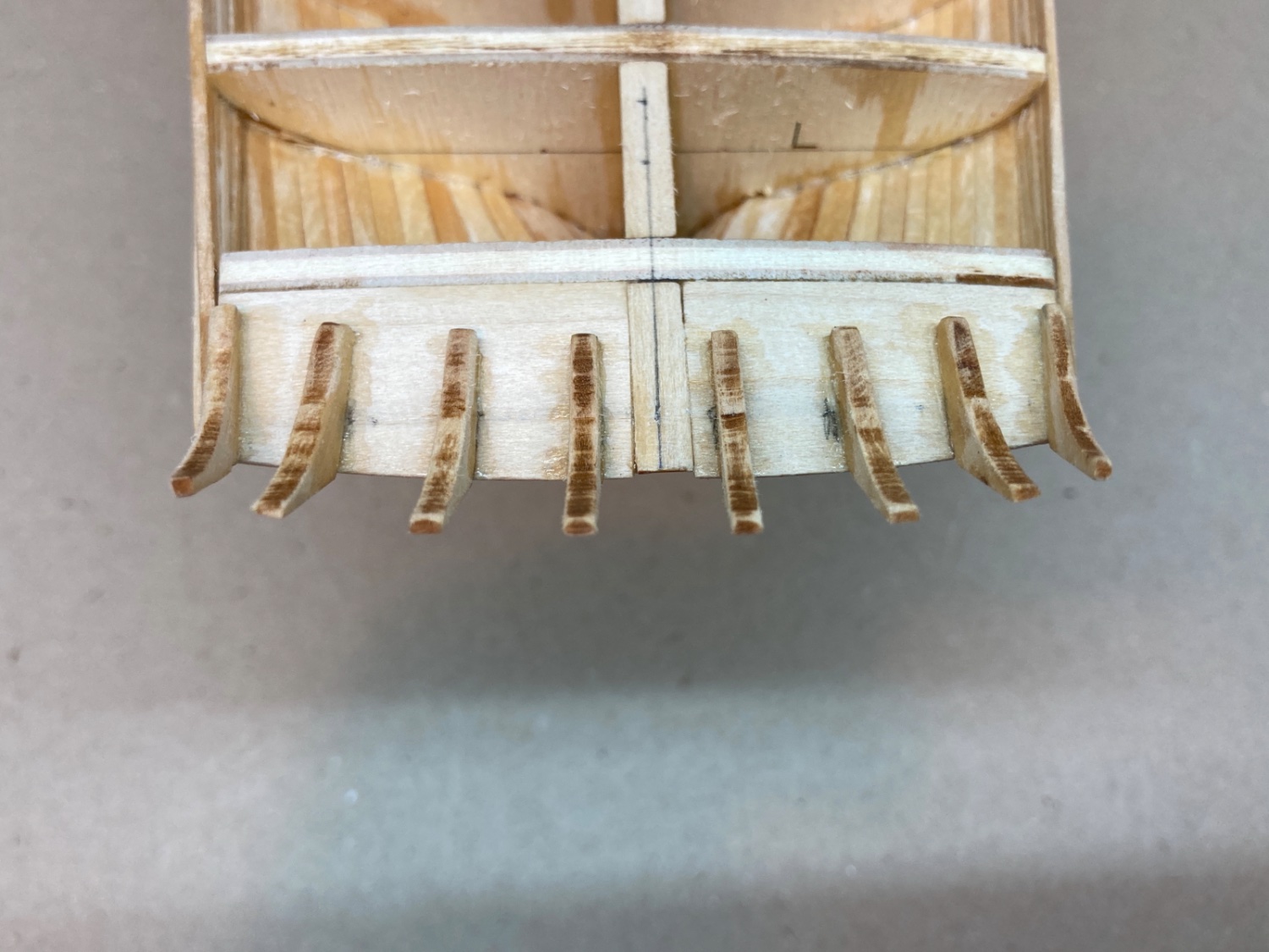
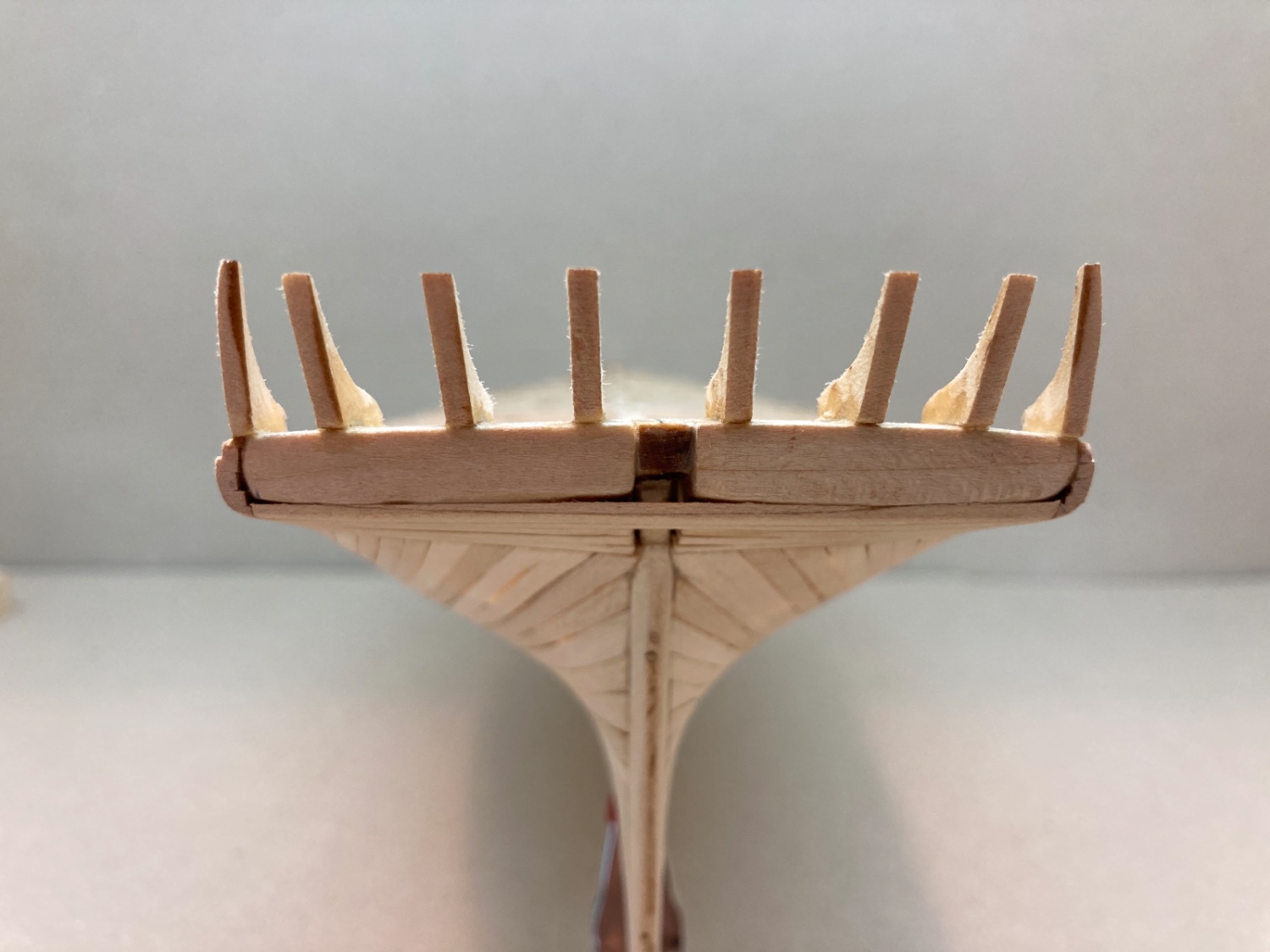
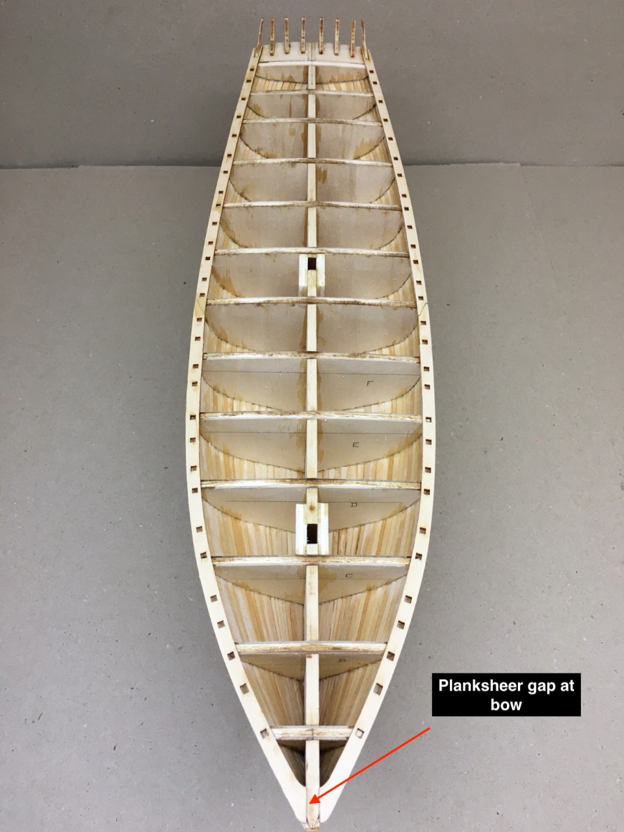
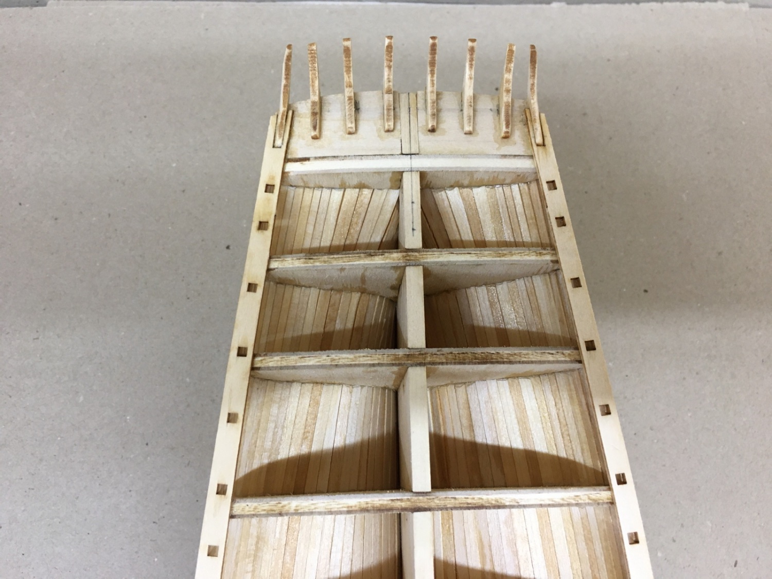
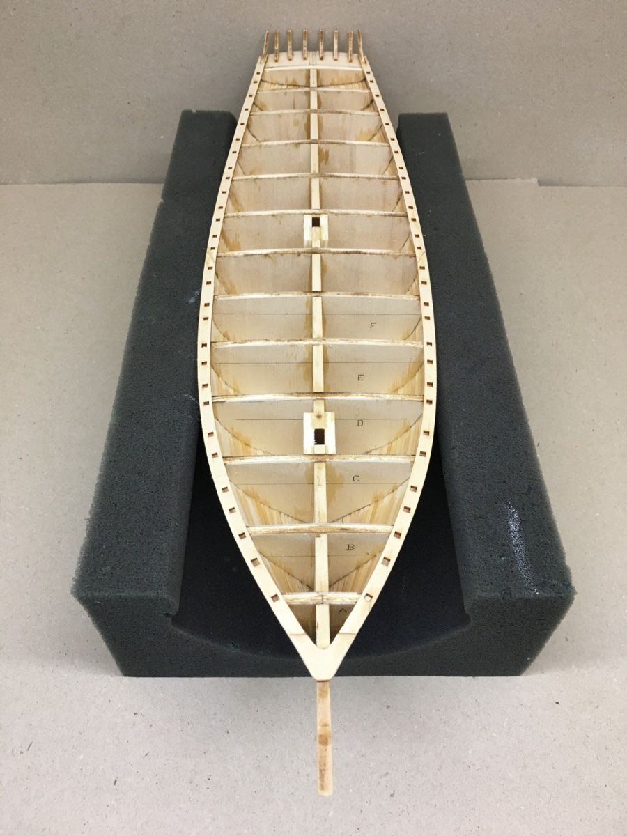
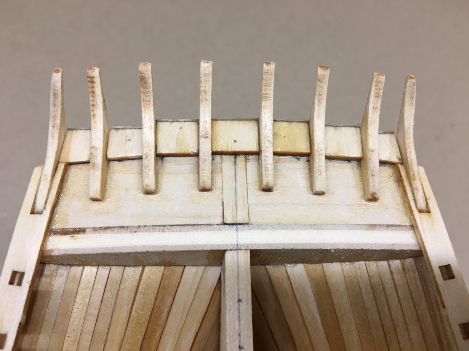
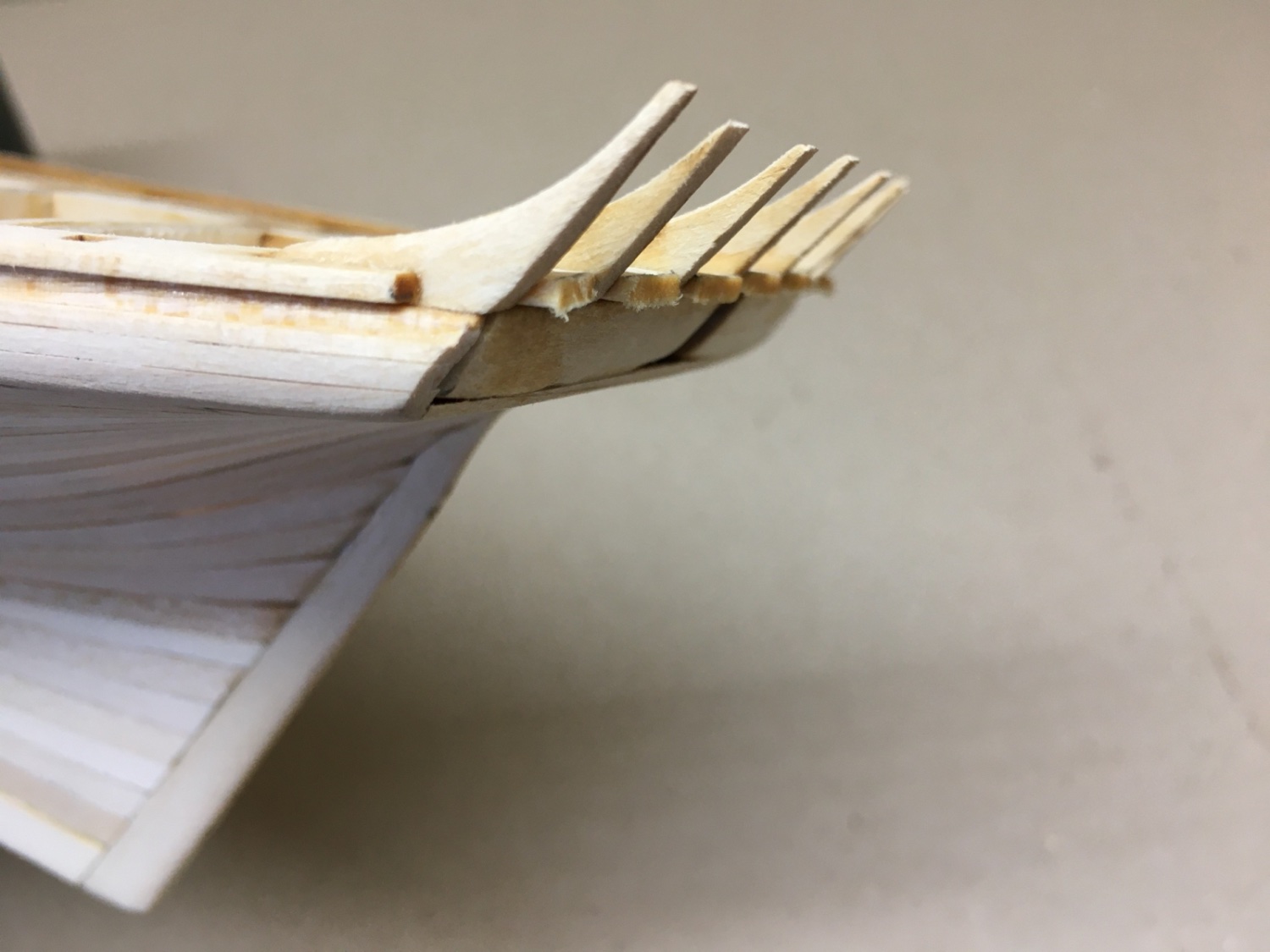
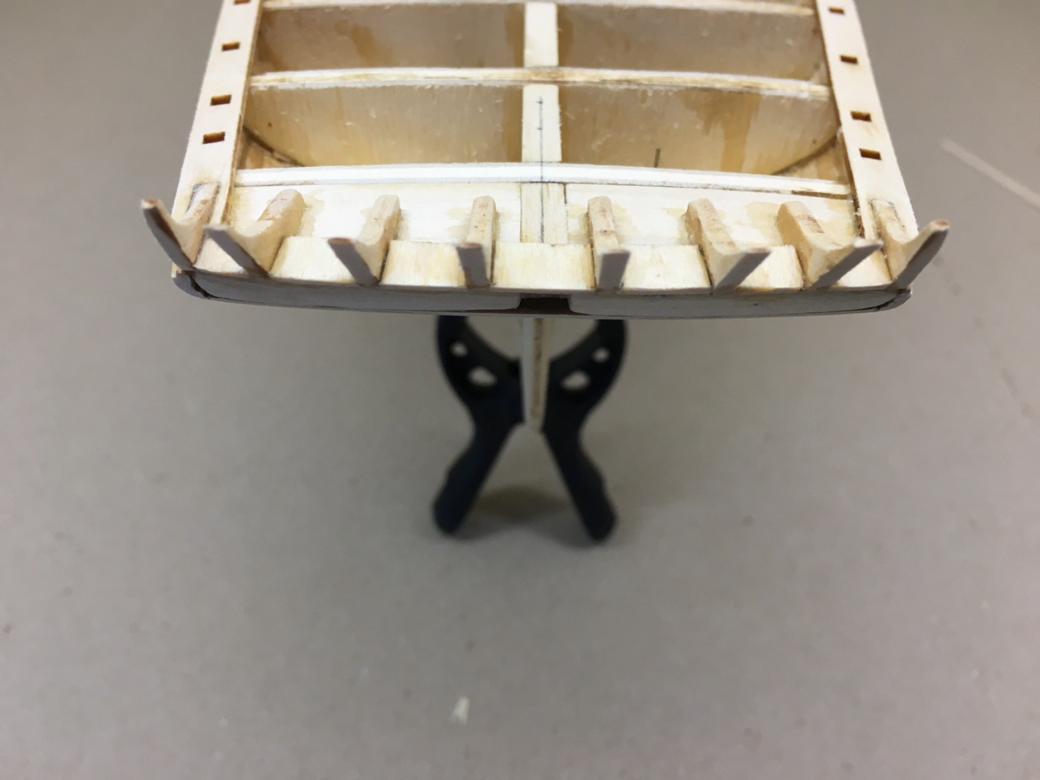
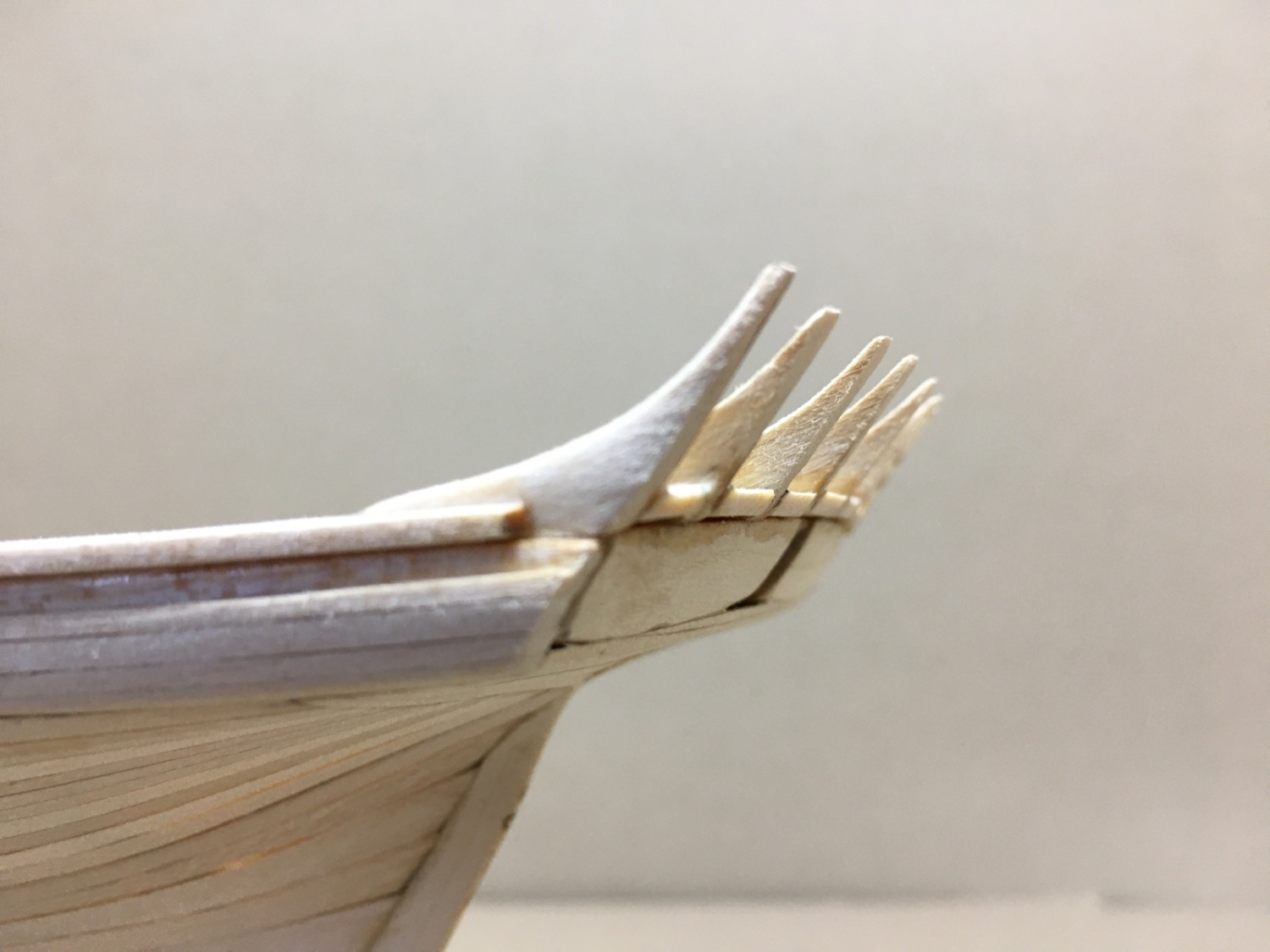
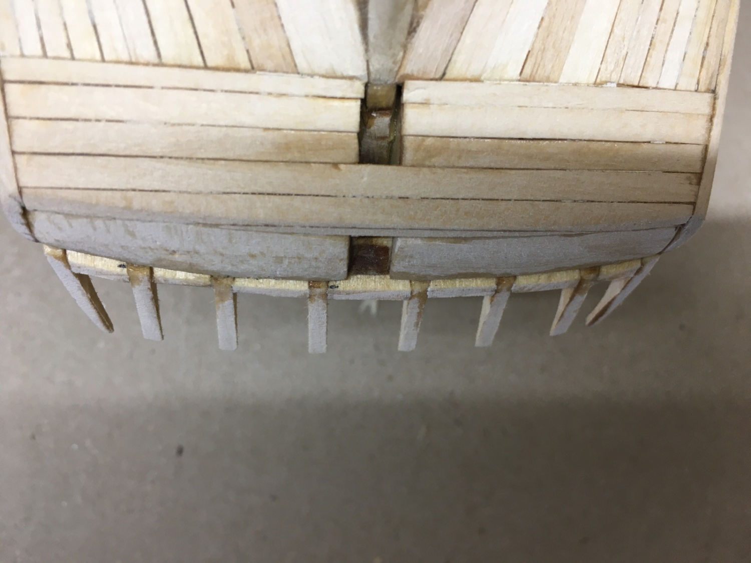
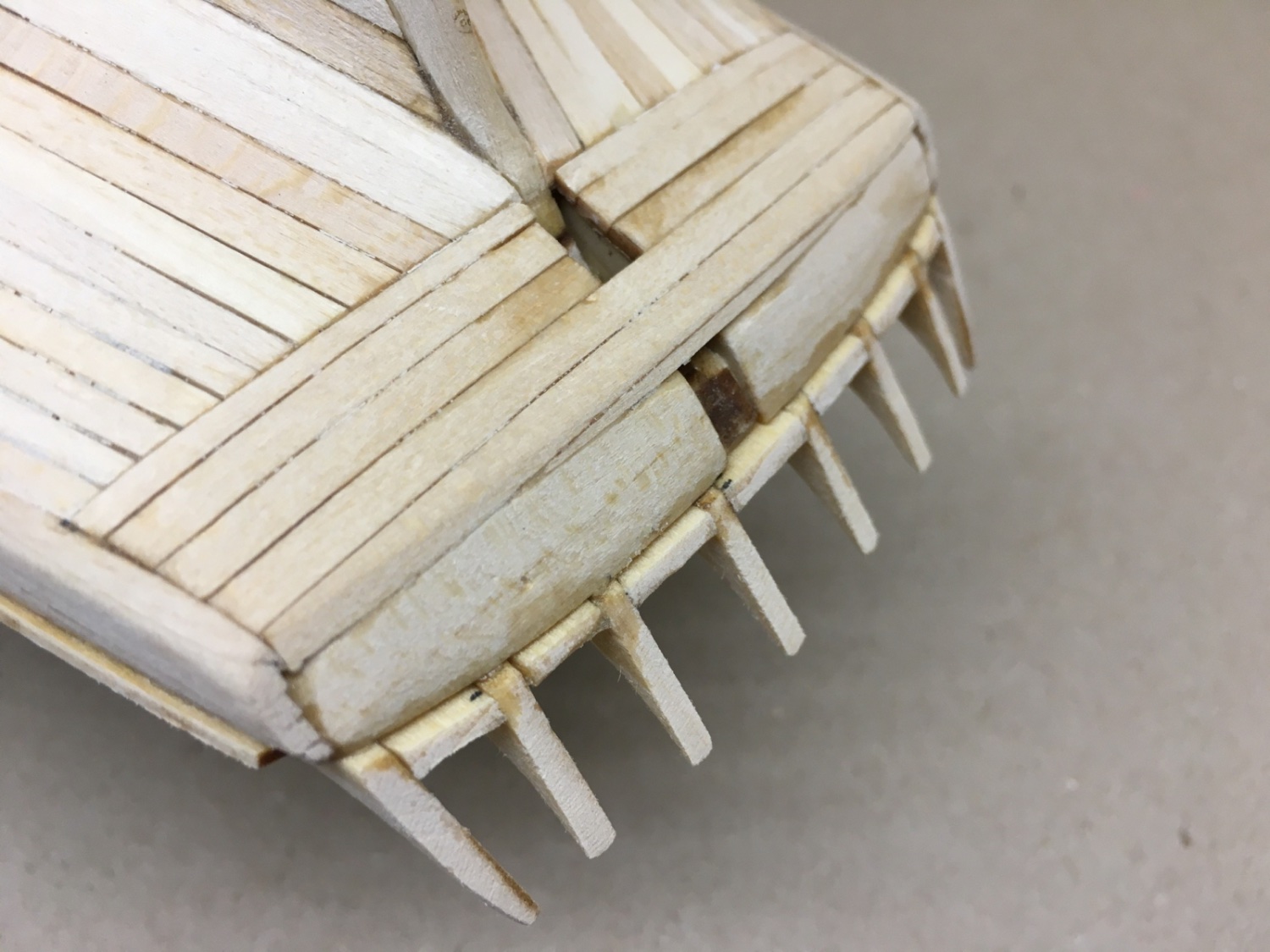
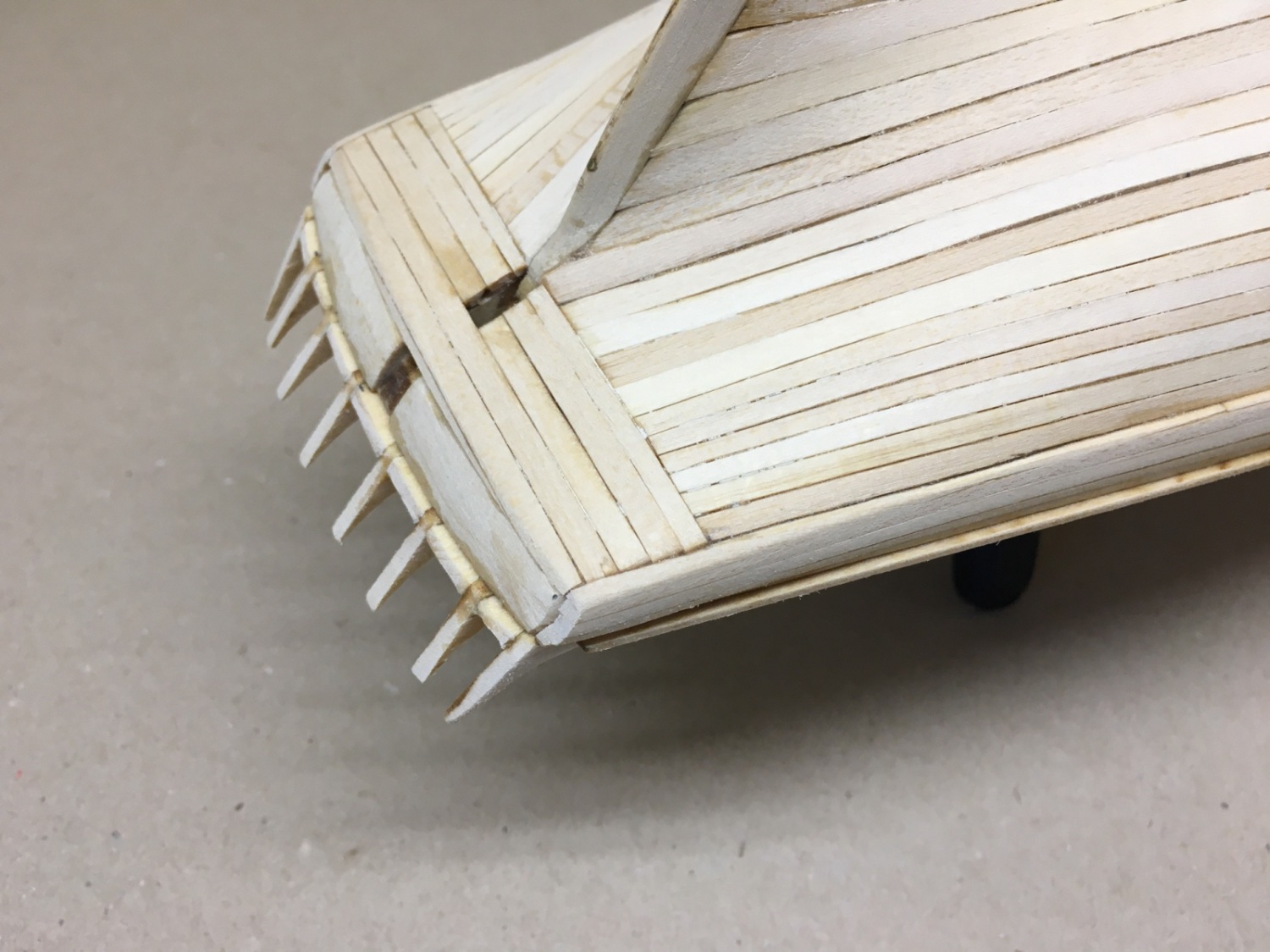
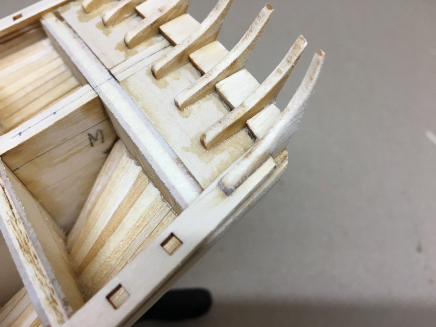
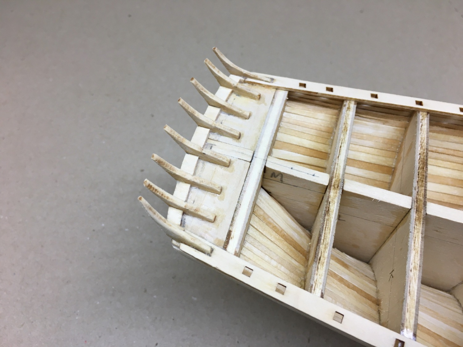
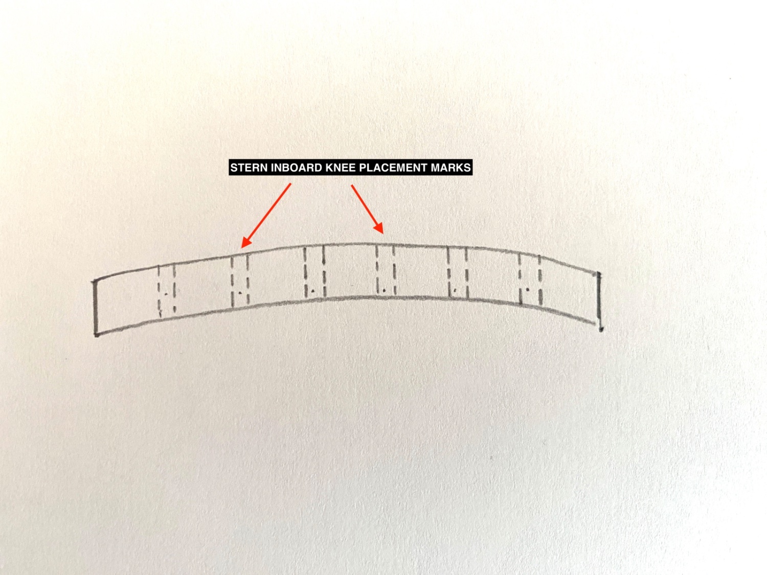
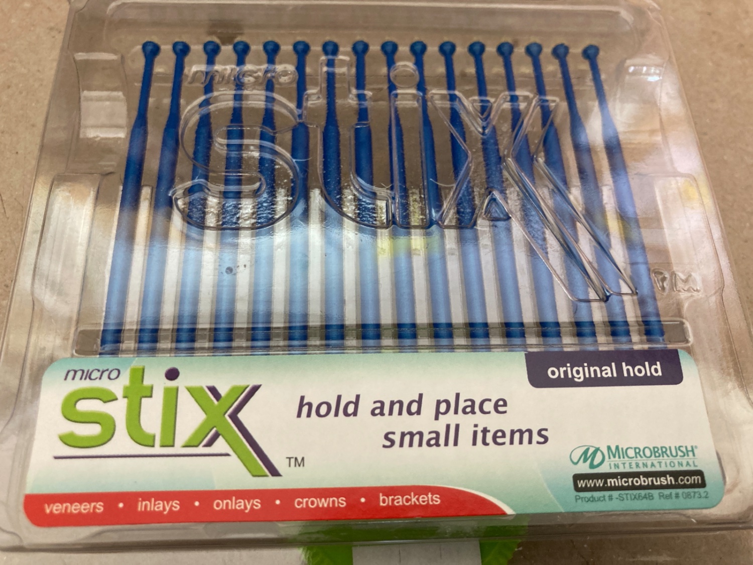
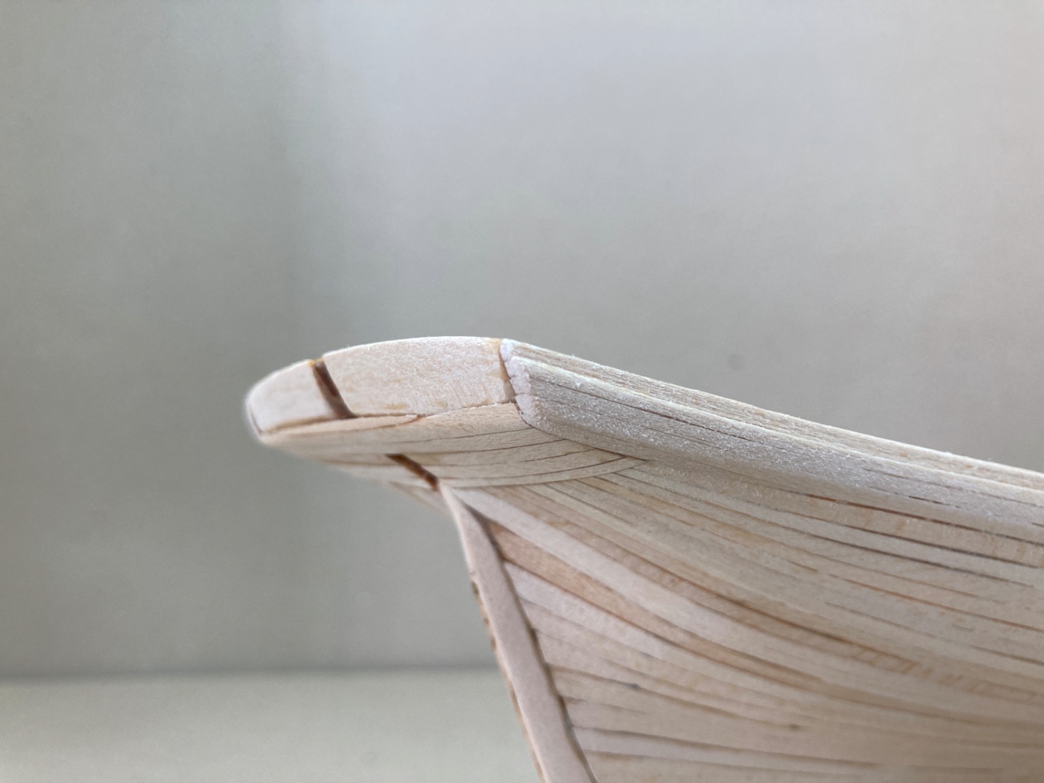
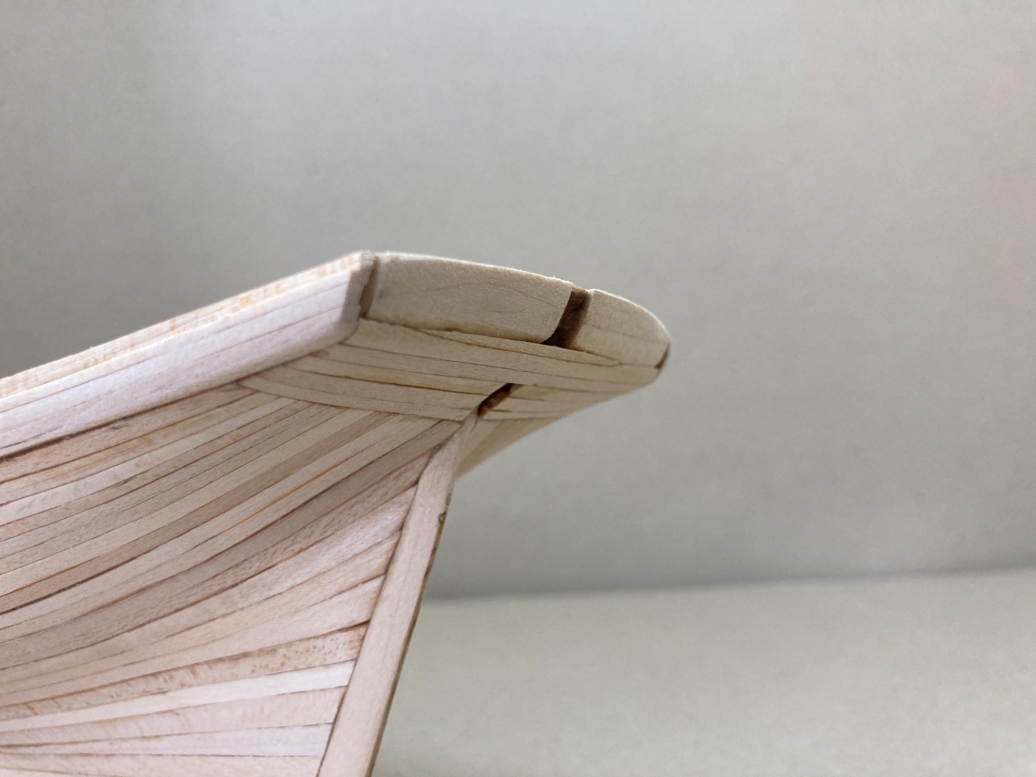
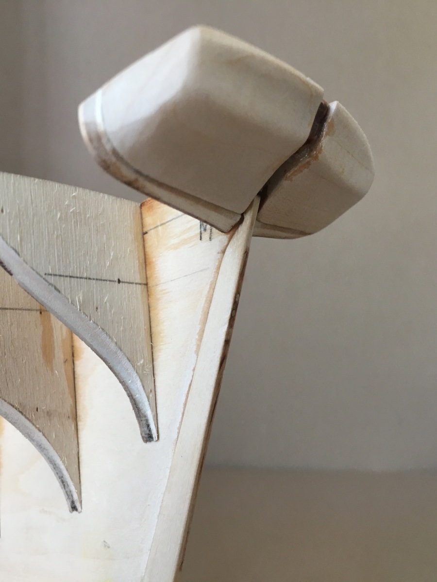
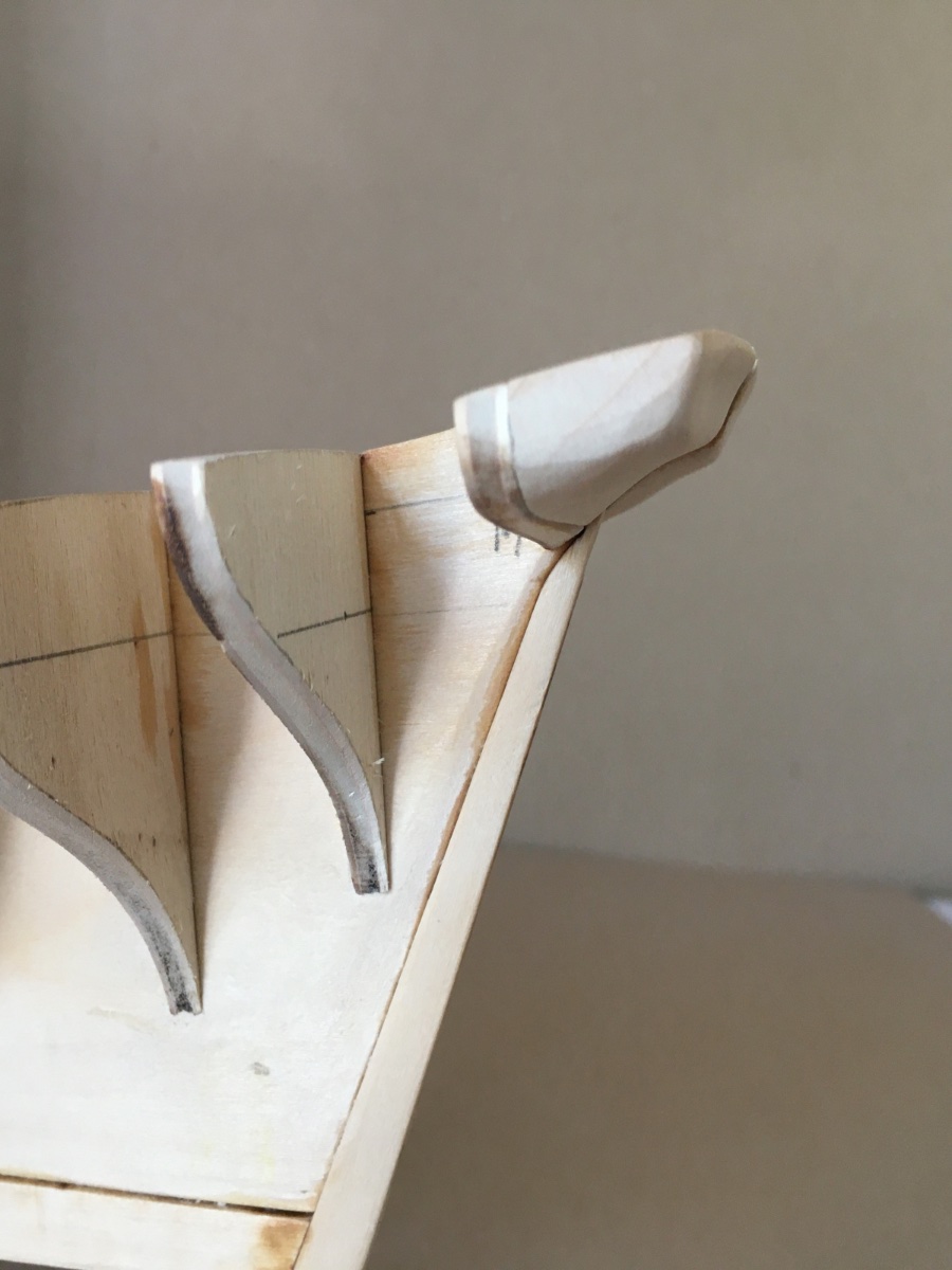
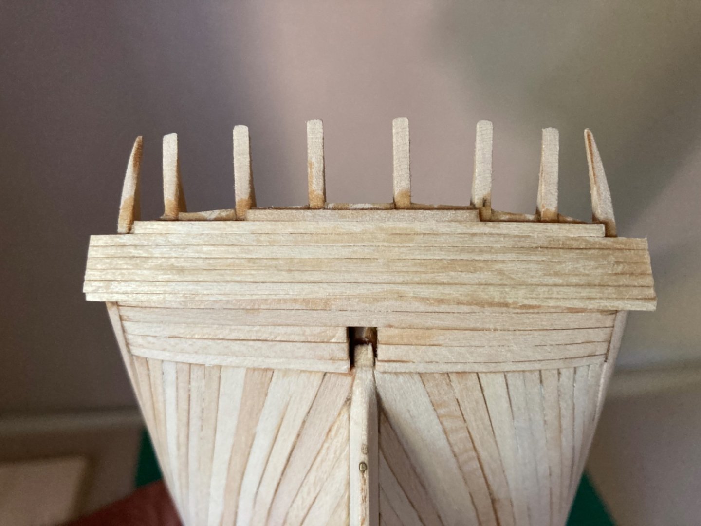
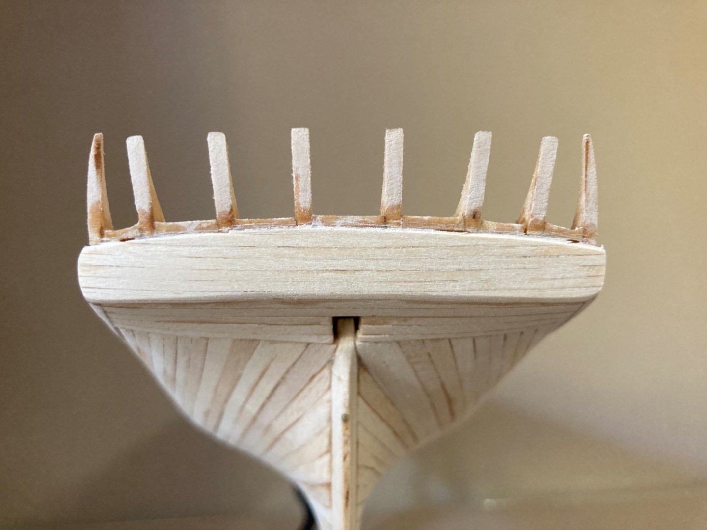
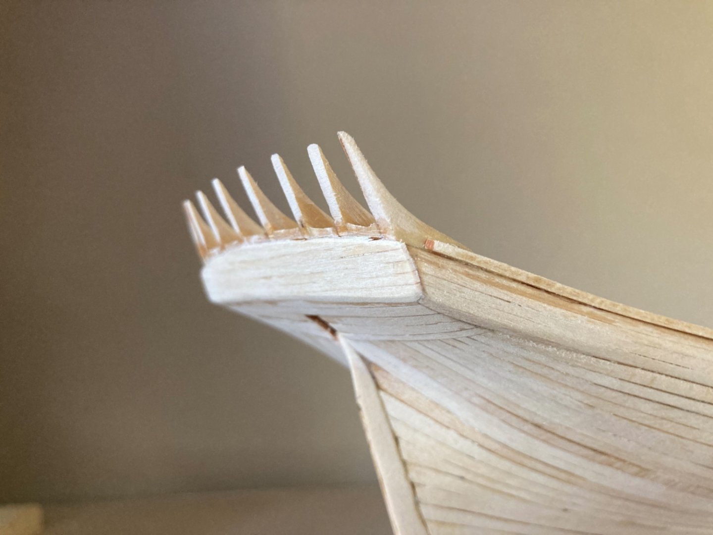
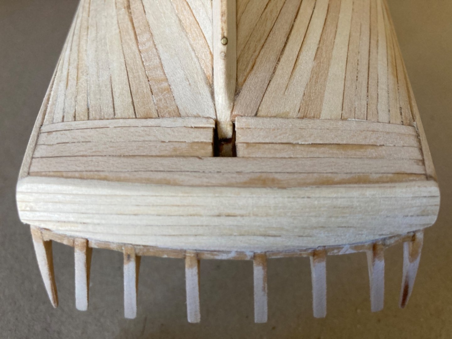
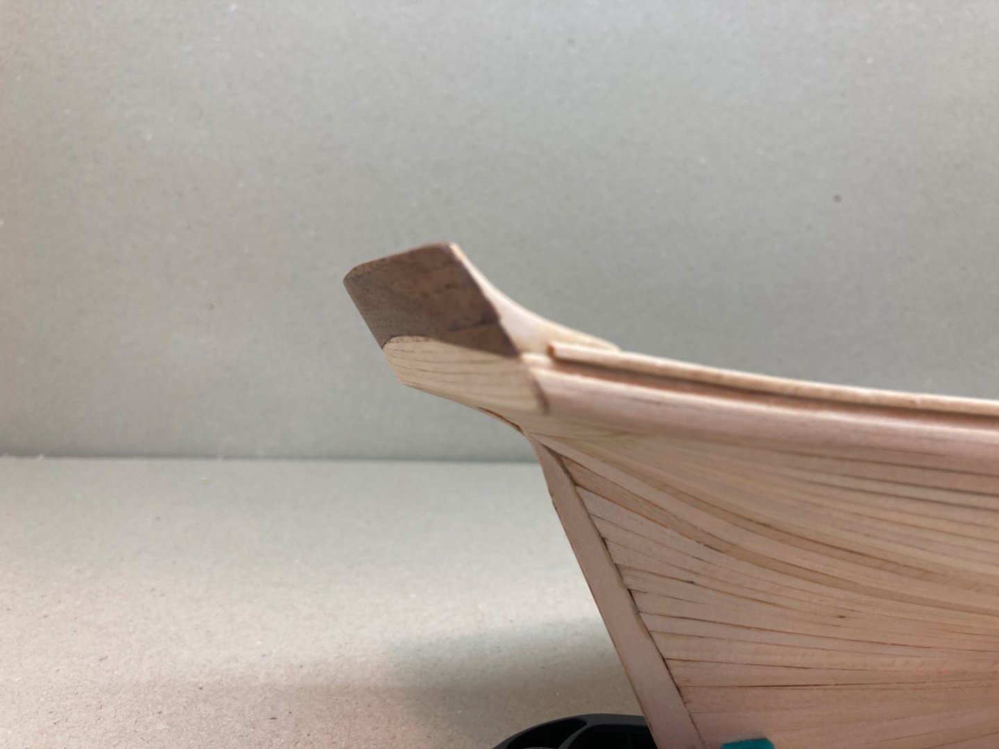
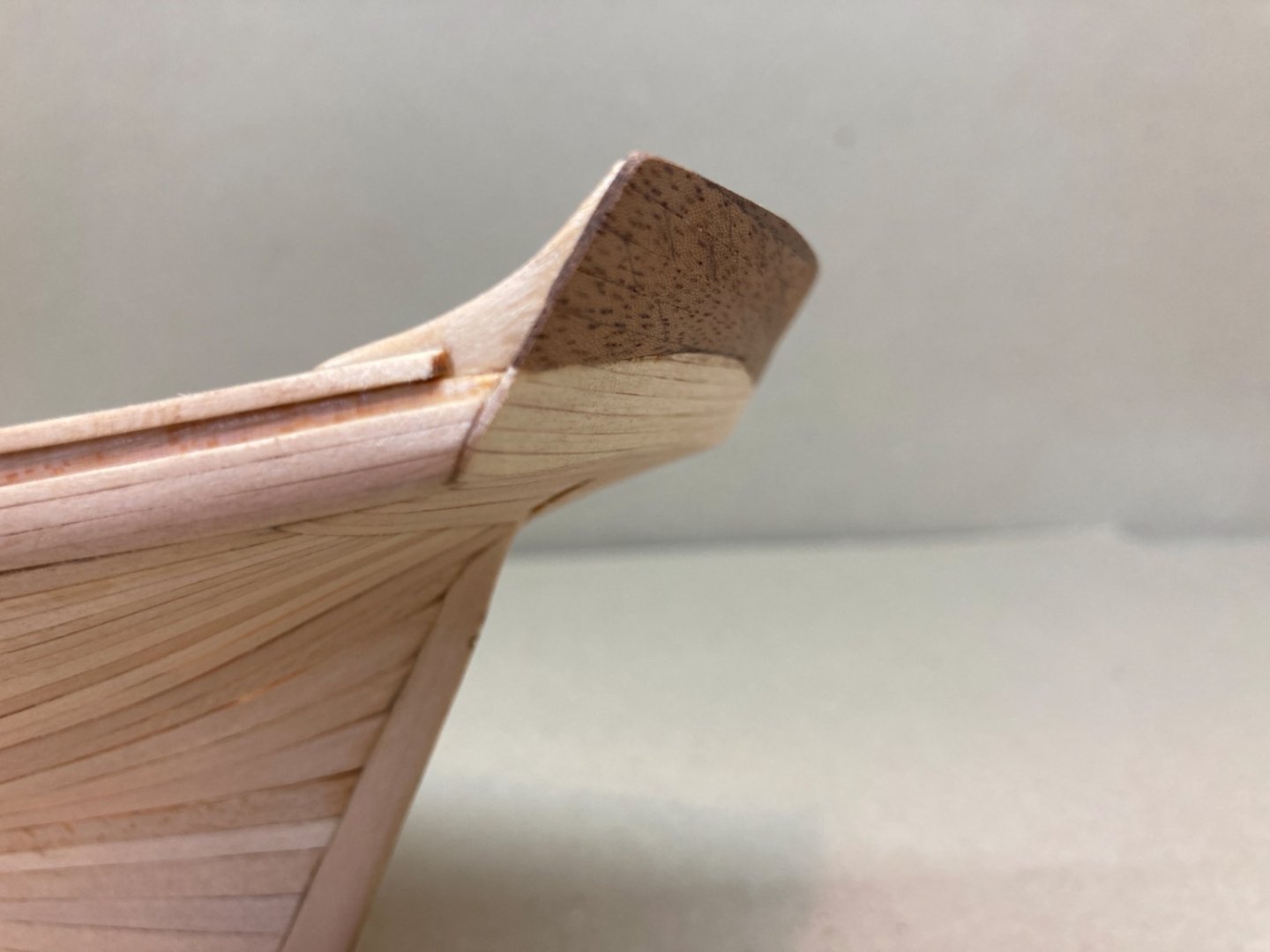
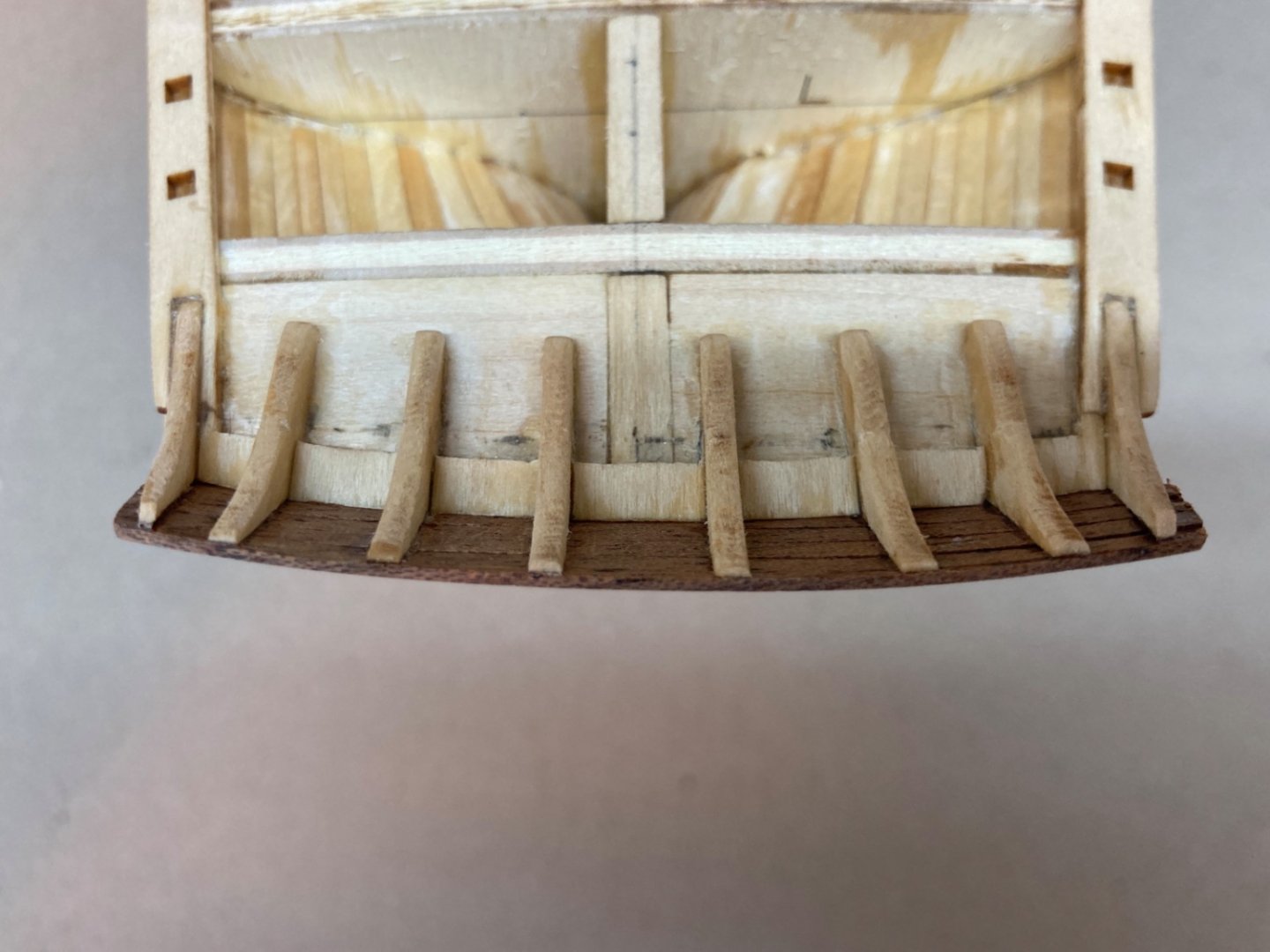
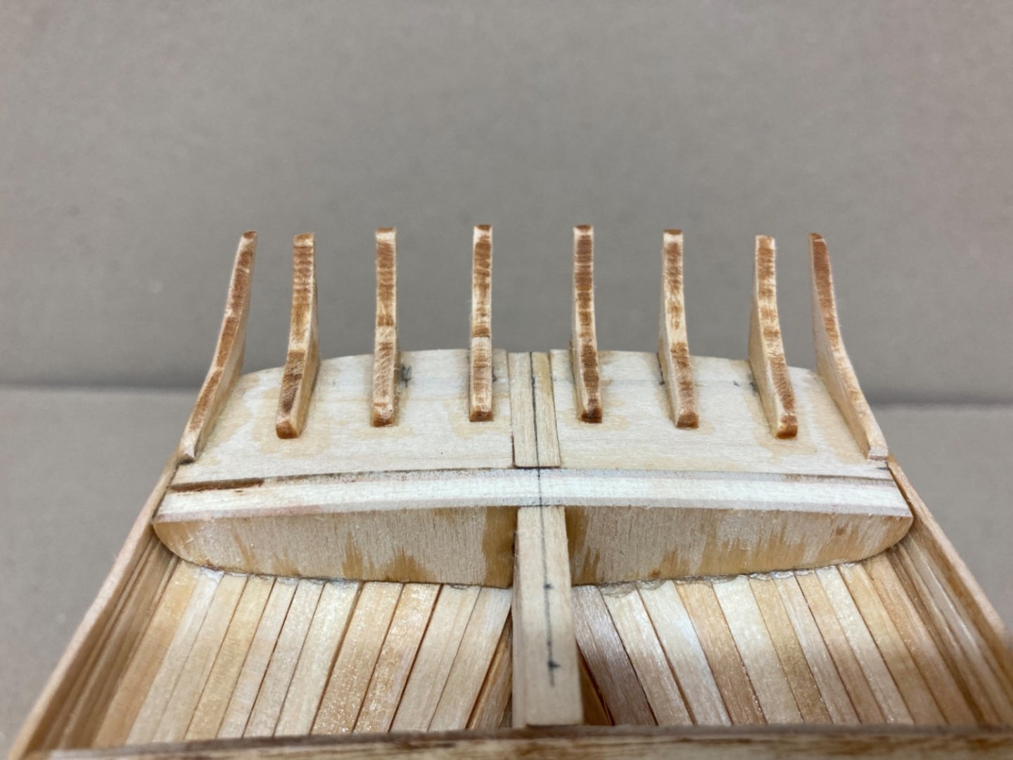
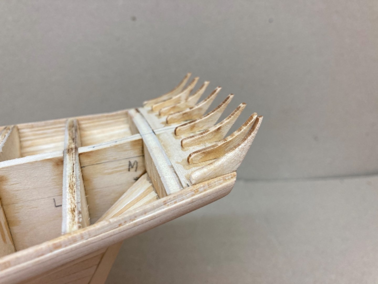
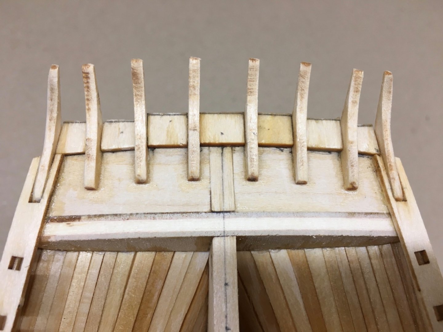
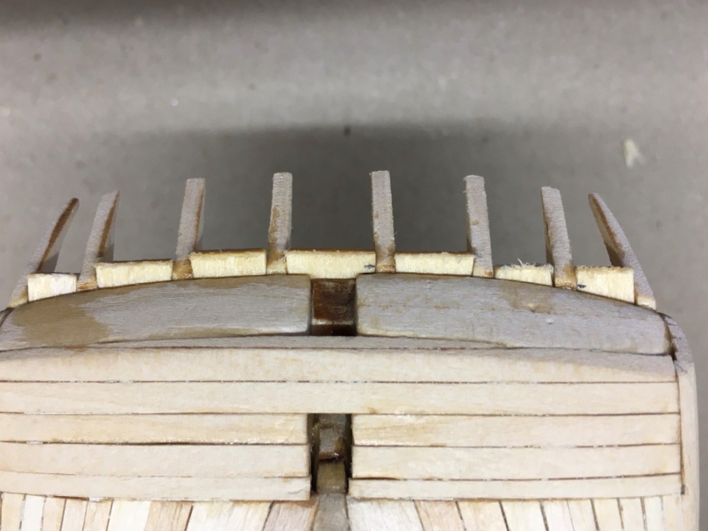
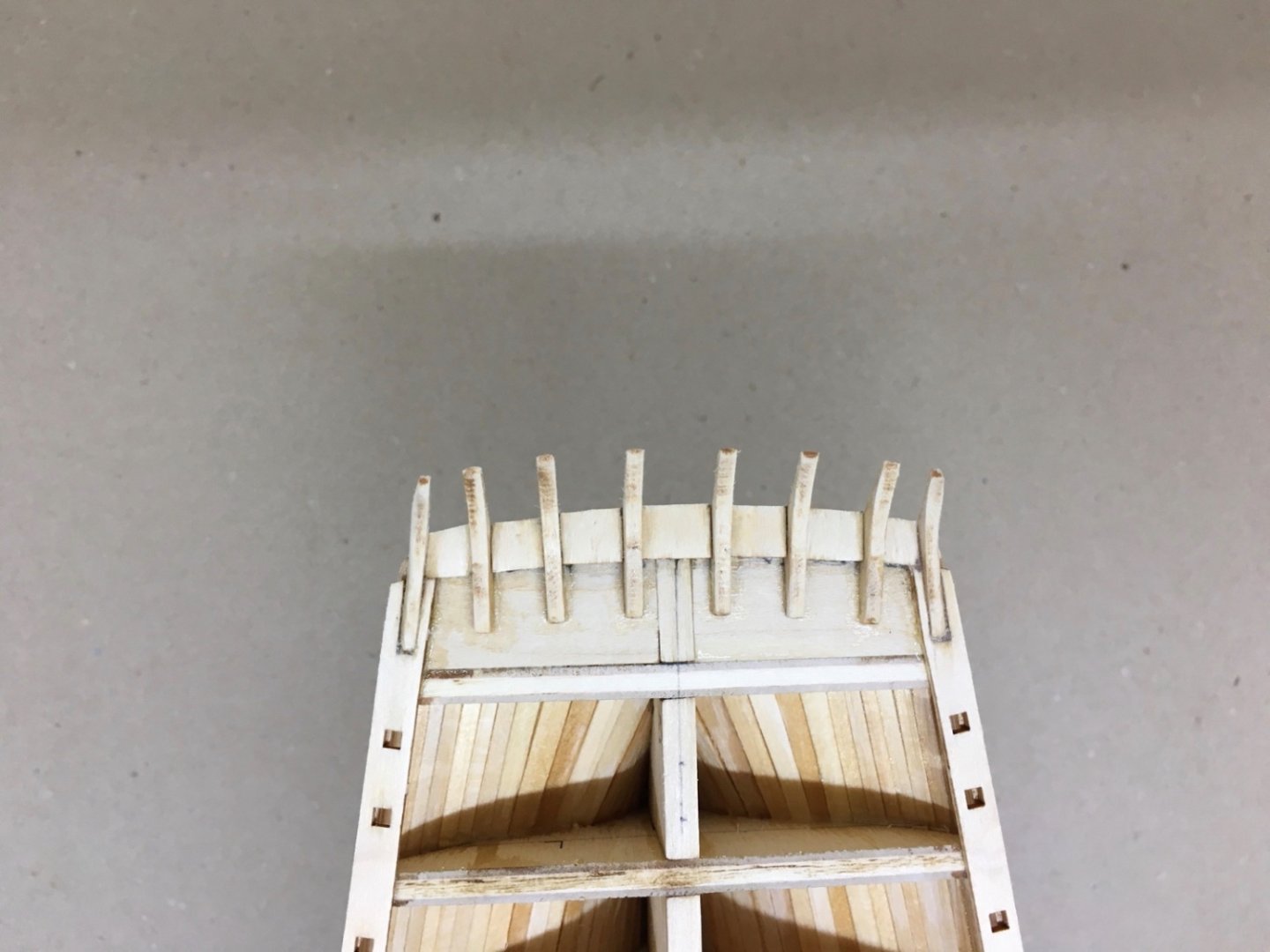
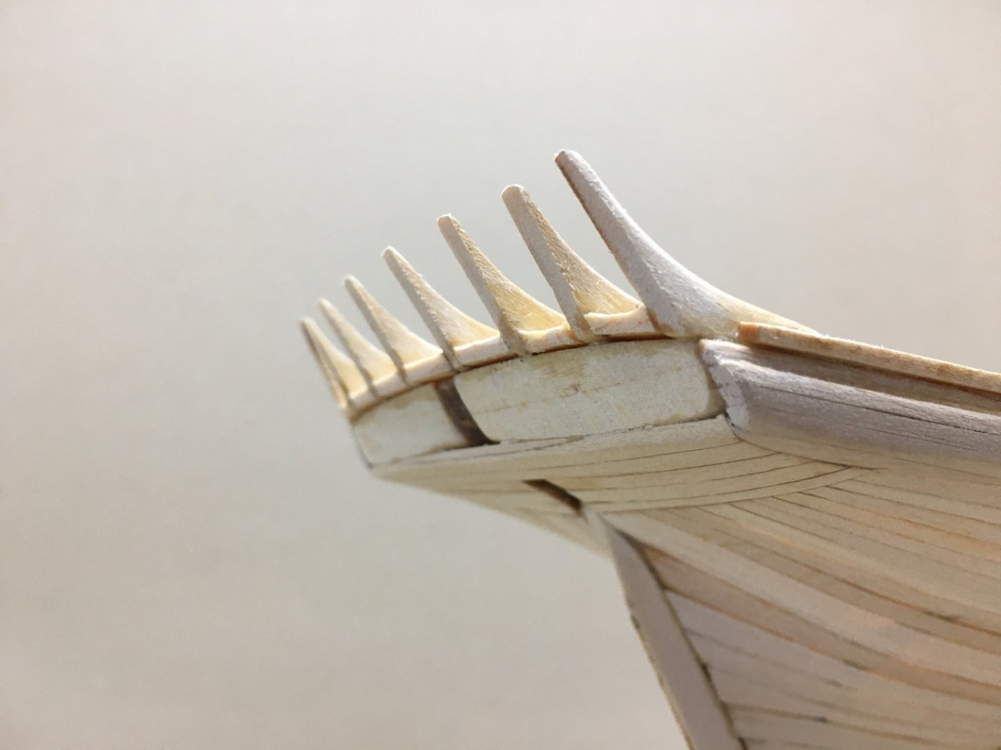
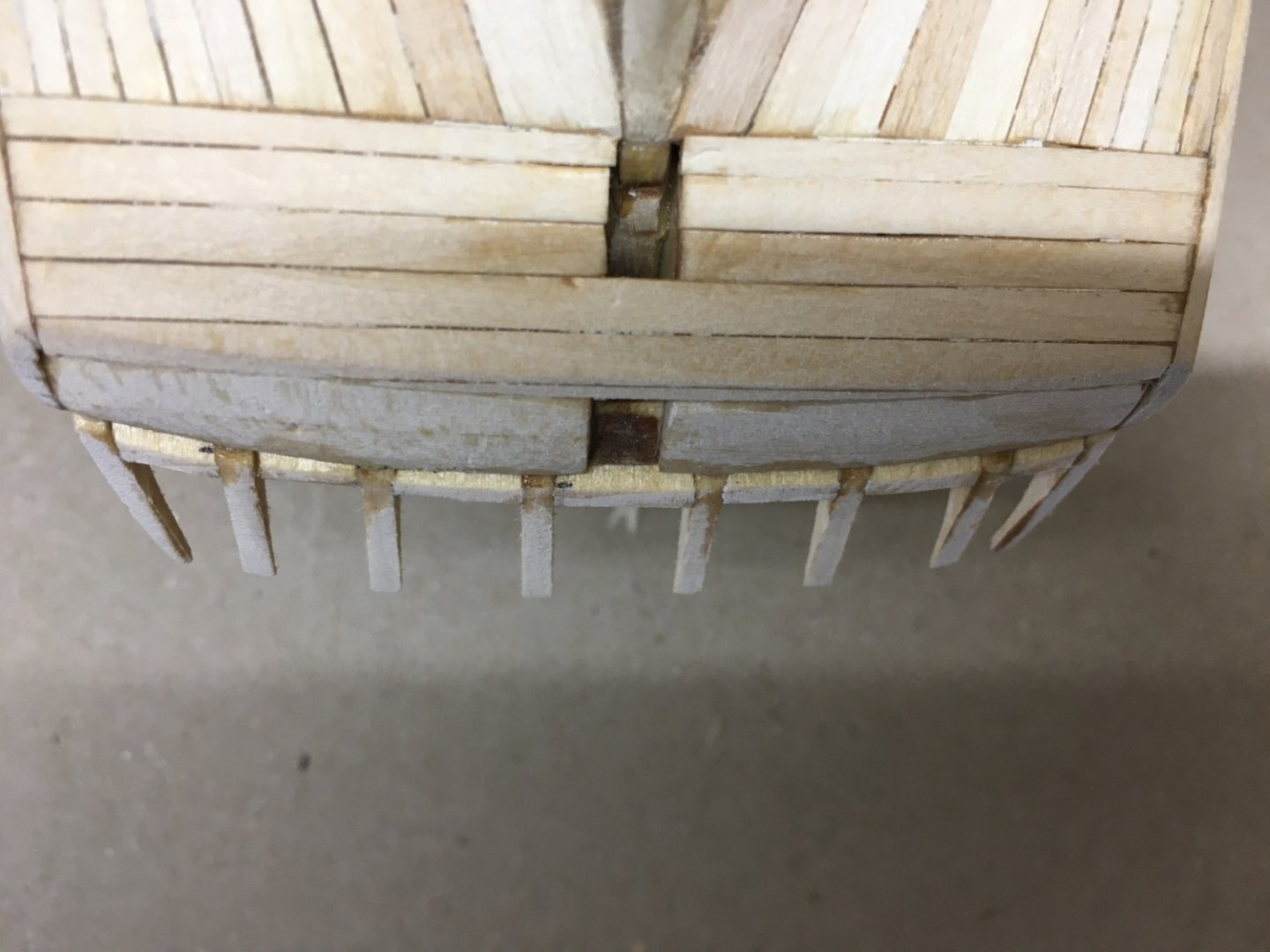
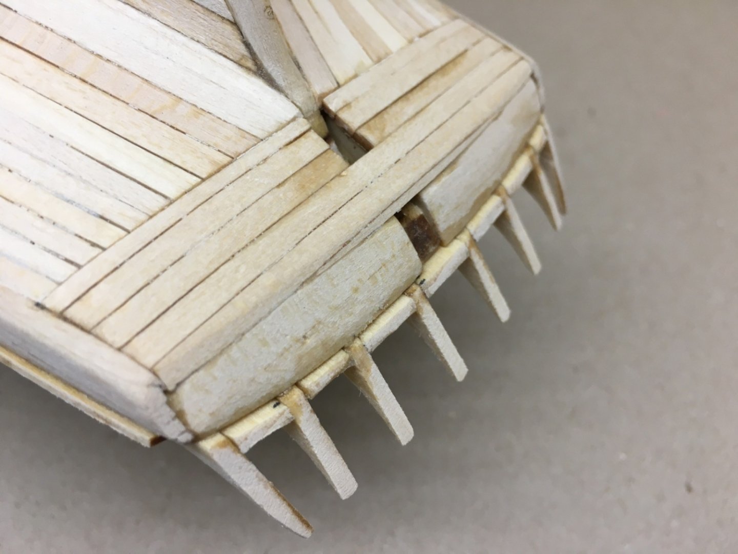
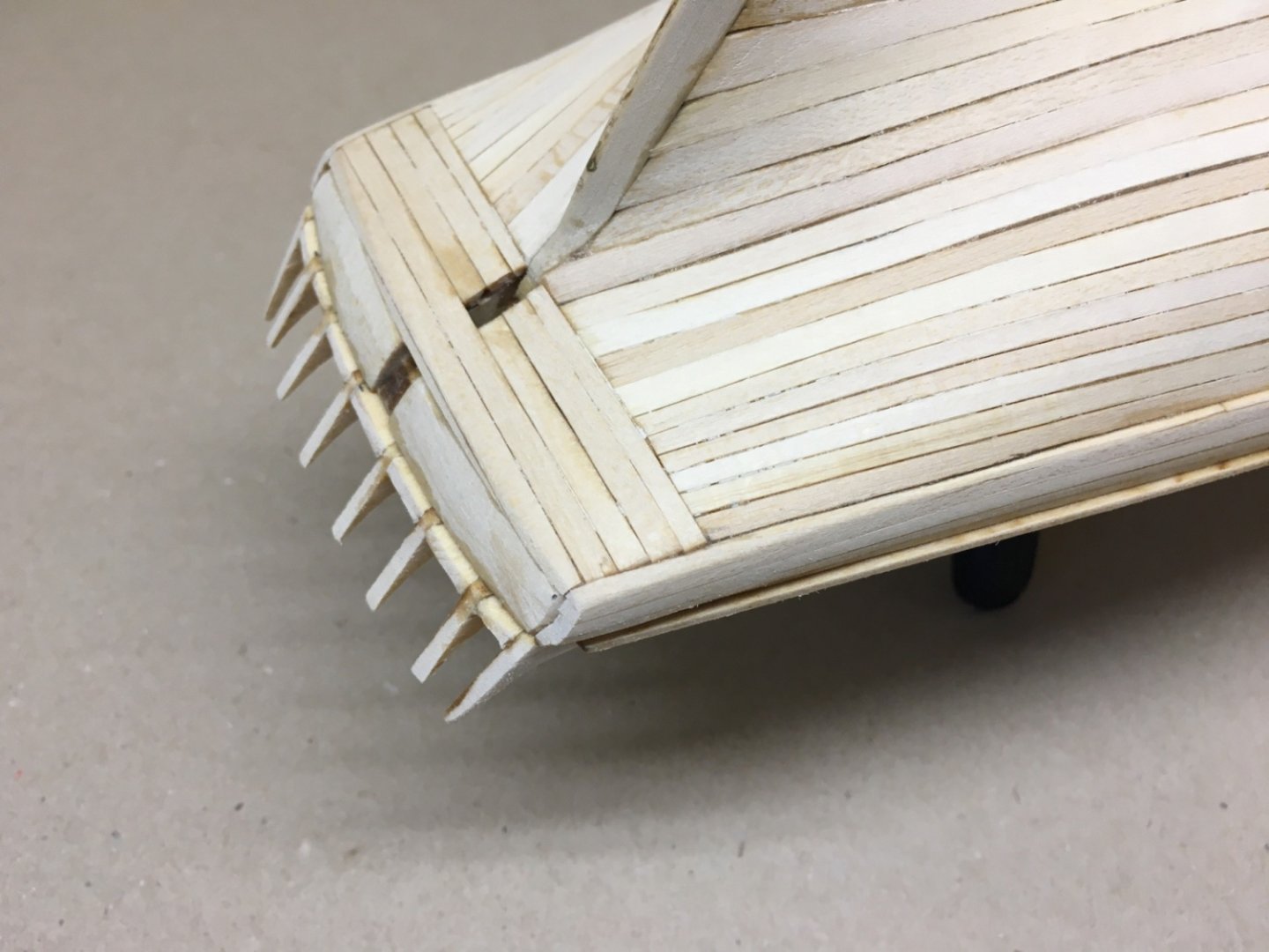
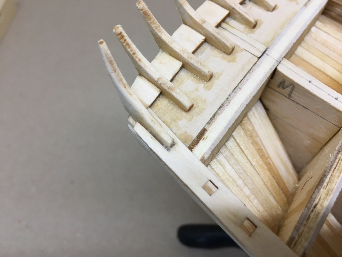
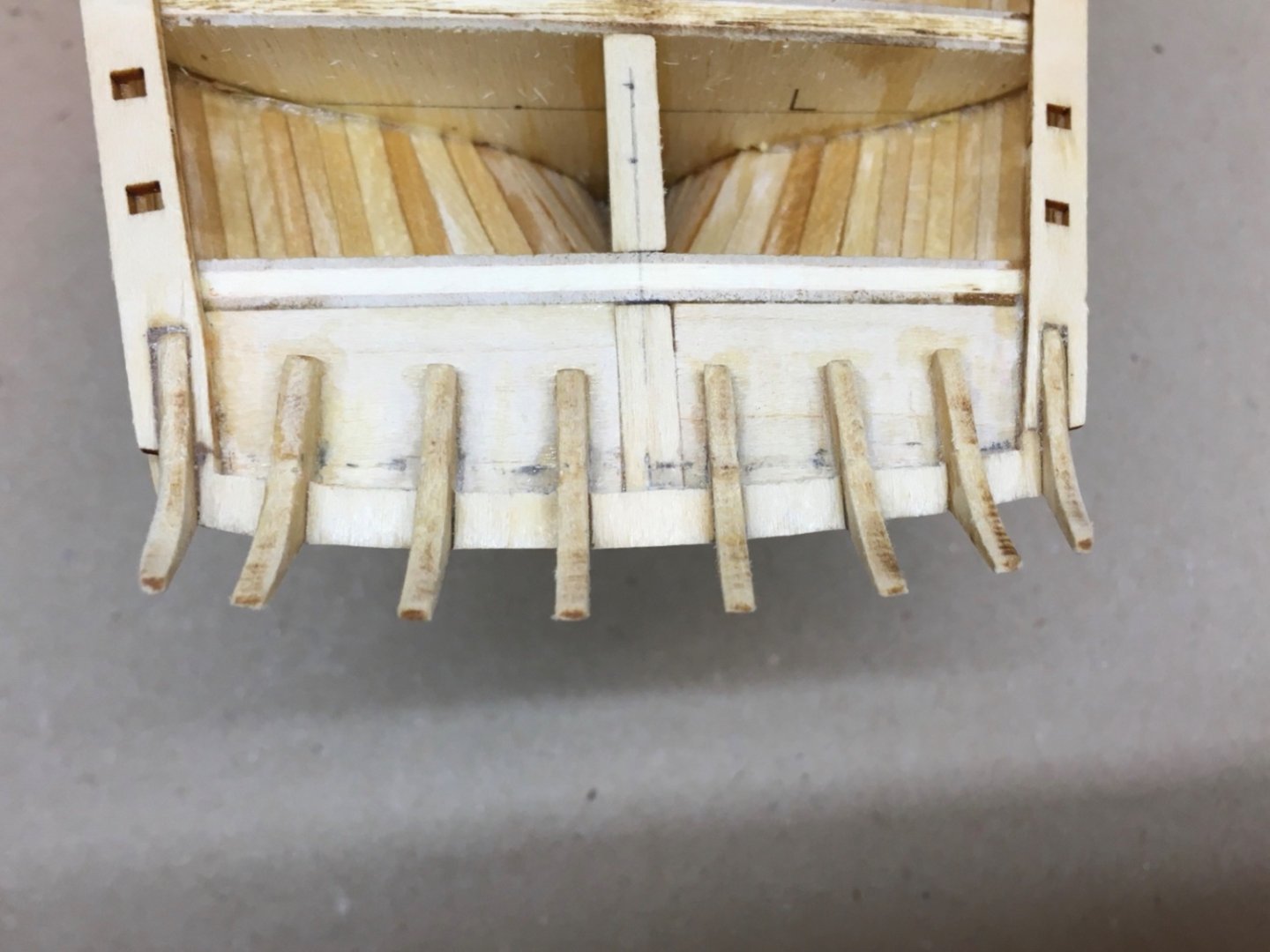
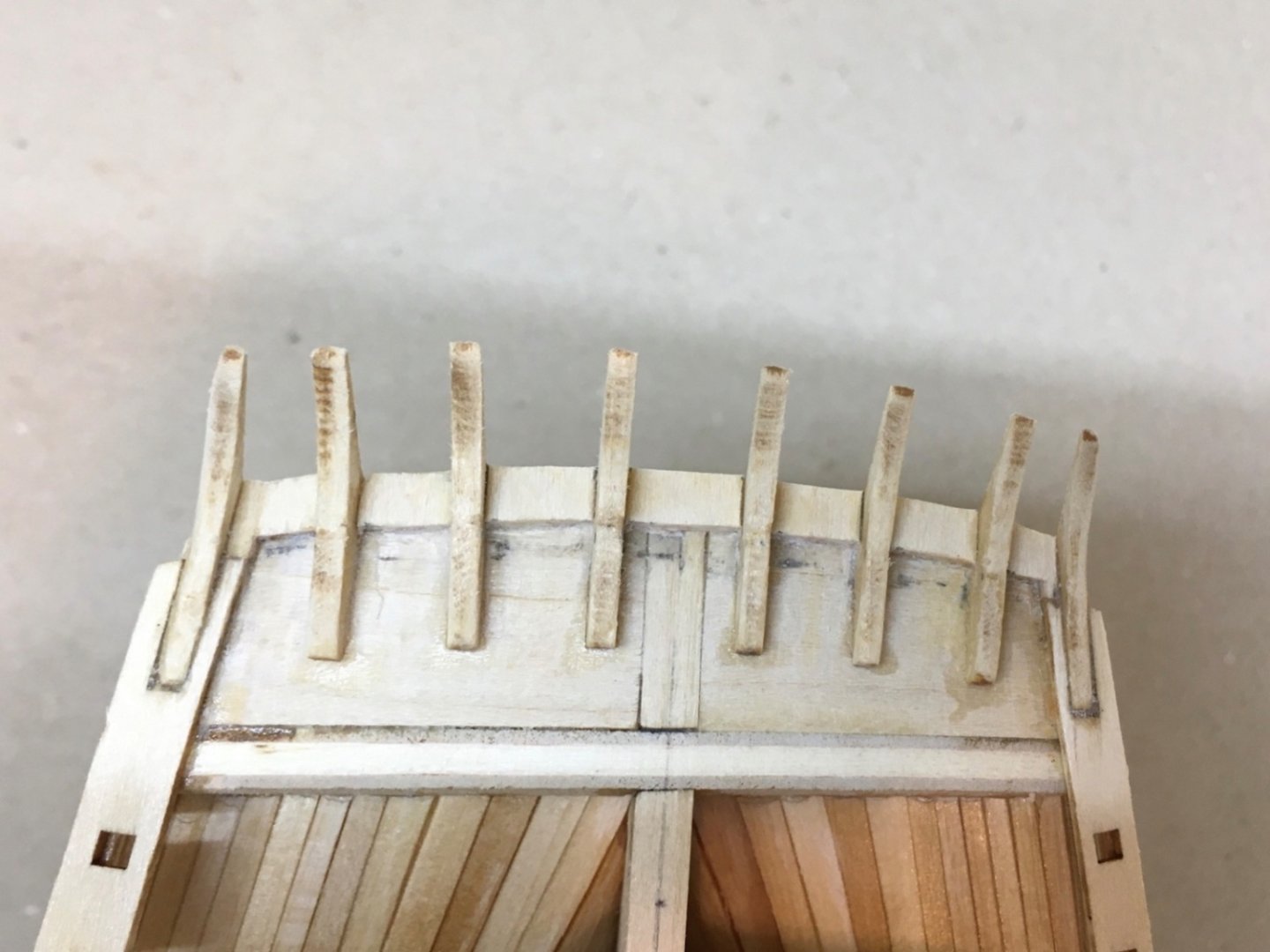
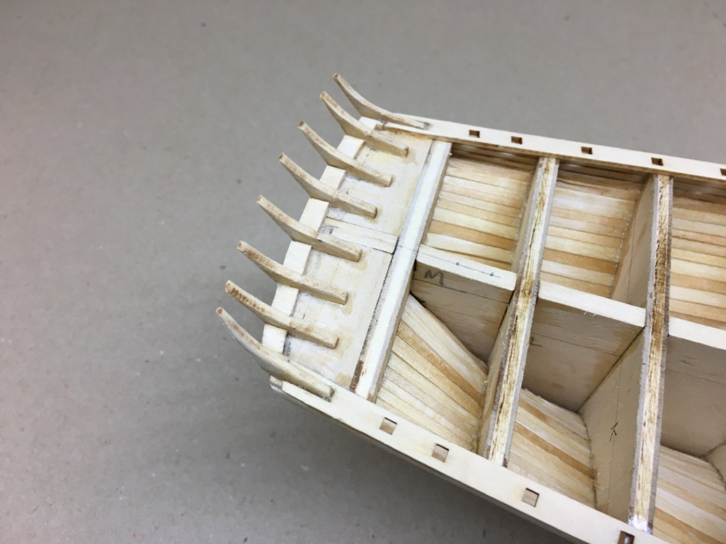
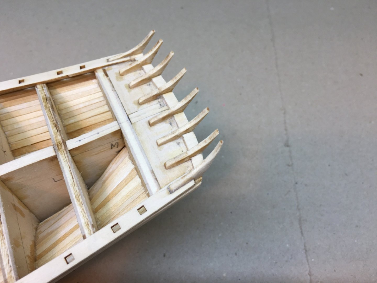
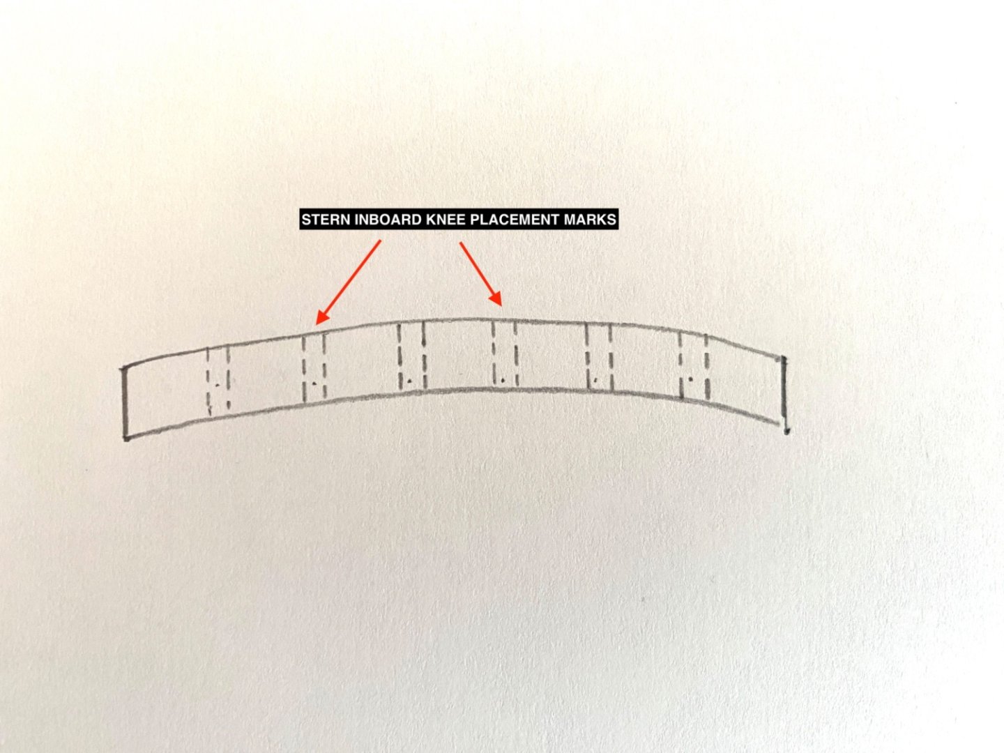
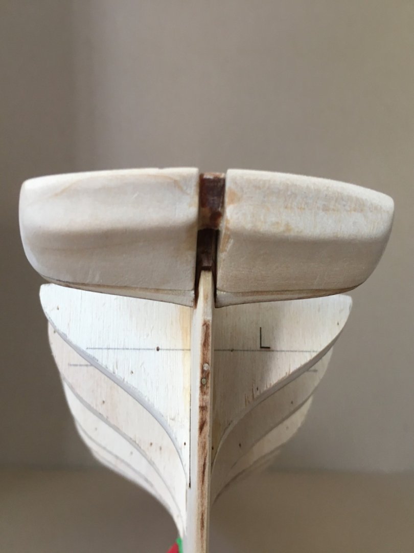
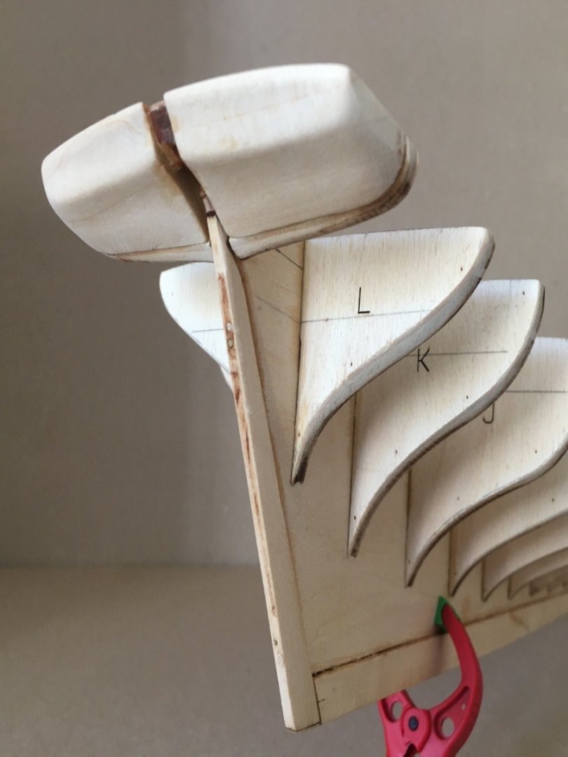
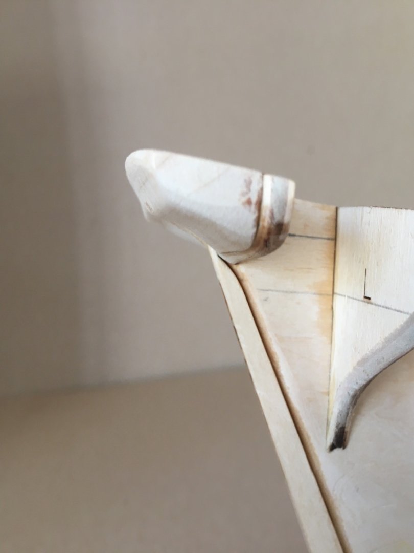
At this stage I made a decision to continue with the wood work on deck and postponed the sanding sealer job of the hull until the planksheer, stern knees, hawse timbers, deck planking , placing of the deck coamings and transom planking are done. Then do the sanding sealer on all ready wood section alltogether. I started with covering the mast slots in the center keel. Fore mast slot Main mast slot At bow the thickness of the first plank is increased and made flush with the wale planks by placing suitable shaped planks on both sides. Starboard side Port side I continued with the installation of the stern knees. There are 8 knees. 6 inboard and 2 outboard at the sides. The outboard knees slope inwards and must be sanded to a curve at outboard sides. Then comes the installation of planksheer . Planksheer on both sides is two pieces first to be glued together. The aft end of planksheer is fork shaped and engulfs the outboard knees. Once you dryfit the planksheers and first placing them at aft side to ensure the proper neighboring with the outboard knees, you realize that their bow ends are short and do not touch each other. This was a flaw of the kit observed almost by all the previous builders. By using the 'short' bow ends of the planksheers ' as guides and using the wood sheet where they were cut out, a new bow ending is drawn and cutout. By proper placement and markings, the original bow endings are cut and new one is placed instead. As the planksheer overlaps the first hull plank by 0.8 mm ( 1/32 inch) , a piece of 0.8x0.8 mm ( 1/32x1/32 inch) wood strip is used as a guide to ensure it. Side views of planksheer at bow. It's level is a bit higher than stem which is a desired result the small gap between the stem and bowsprit like in the real ship. Installment of the planksheers is finished The comes step where you must make and place the planksheer between the stern knees. First let me show the way I did it , which later realized was not the proper one. Also I made a measurement mistake when preparing the pieces. The width of the planksheer between the knees is 4.5 mm ( roughly 3/16 inch) . However the width of my pieces were 6-6.5 mms . After sanding I then marked the width border and carefully cut the excess wood out. Of course the result is far away from a properly done one. I should have removed the newly placed planksheer pieces and the 6 inboard knees and do the job again like the way I described below. However I was afraid of the fragility of the knees after the already done sanding job is so I decided to accept the result and move on. Here is how this step should be done and I am sure many of you will agree with it. After the placement of outboard knees and planksheer , the shape of the desired stern planksheer is drawn on the same board where knees came from. After marking the places where inboard knees will go, the prepared piece is installed on stern border. Here take care not to apply glue under the knee replacement marked parts in order to accomplish an easy cutout later. The cutout job can be done in favour of the remaining planksheer parts and a tight insertion and placement of the knees , after sanding if needed, can be accomplished. I believe this is the way for a uniform finish at this step. There is a critical step at this stage which must not be overlooked. The bottom of the holes in planksheers , which later the bulwark stachions will be placed, are hollow except where they coincide with the upper surfaces of bulkheads. Bottom of the hallows must be covered some way in order to facilitate the proper installation of the bulwark stachions. I used thin scrap wood pieces cut to size and hold by stix sticks from below and applying rapid CA glue from above by self-made applicator.


- 114 replies
-
- 3
-
-
- Pride of Baltimore II
- Model Shipways
- (and 1 more)
-
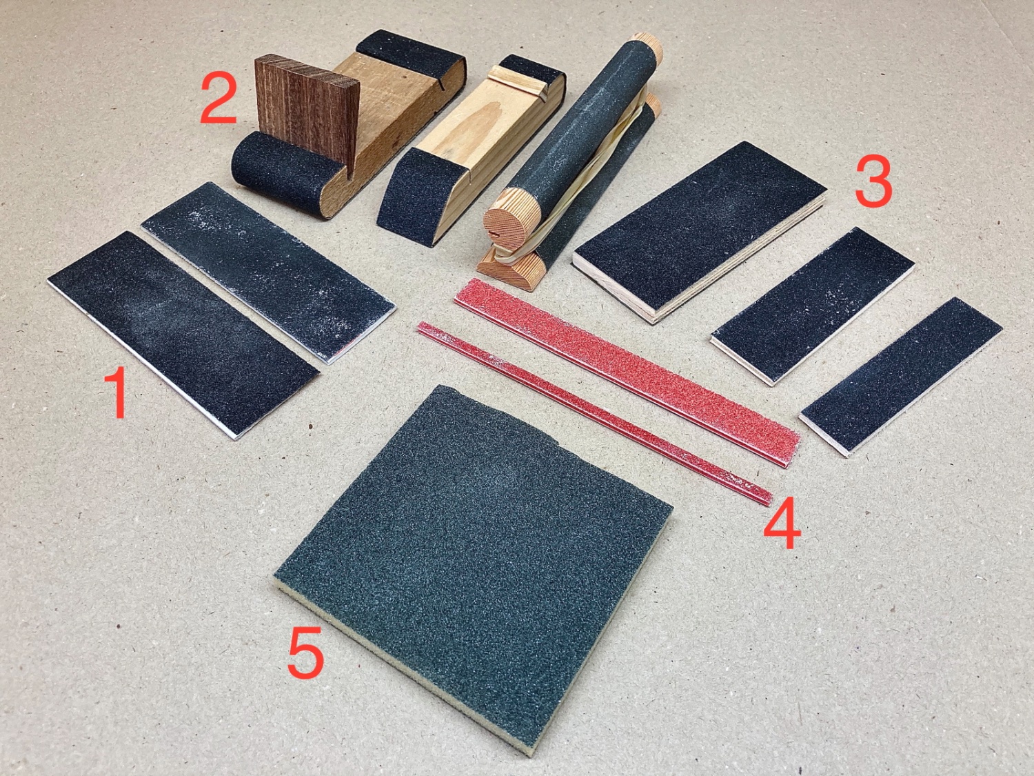
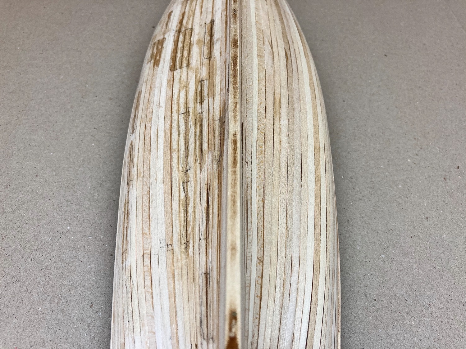
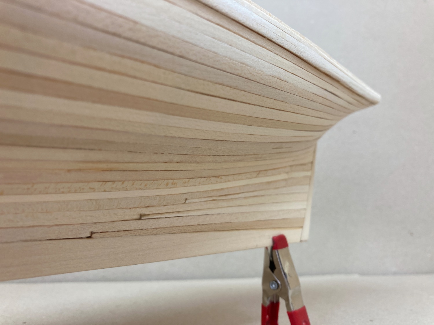
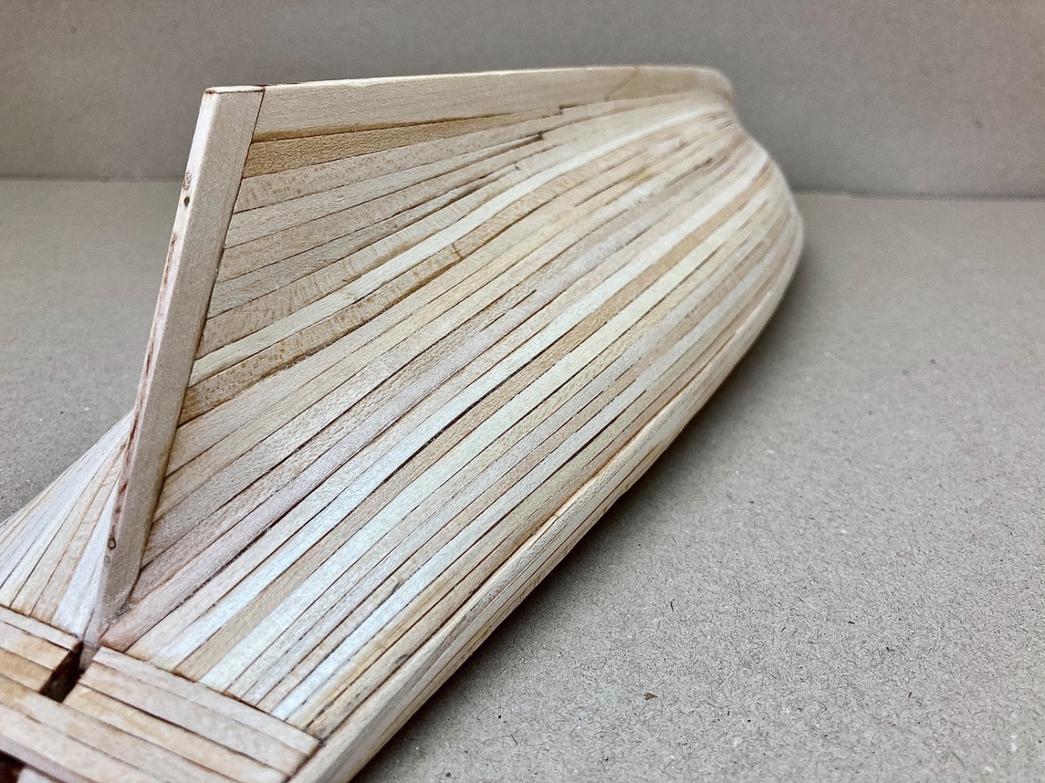
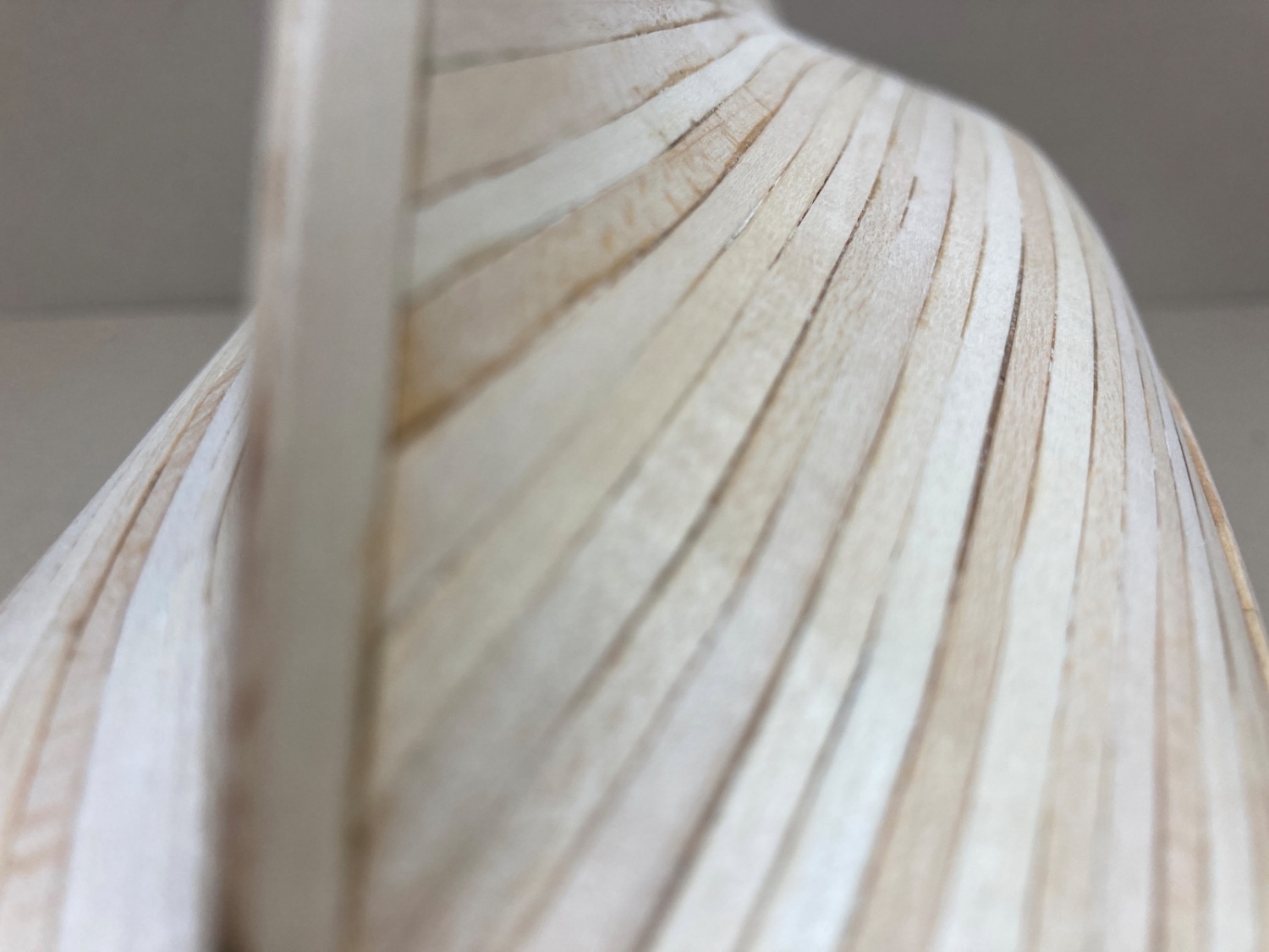
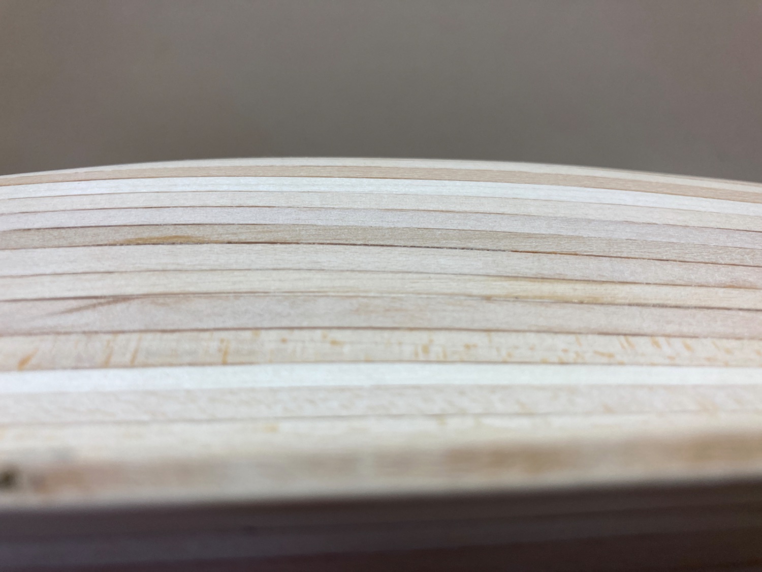
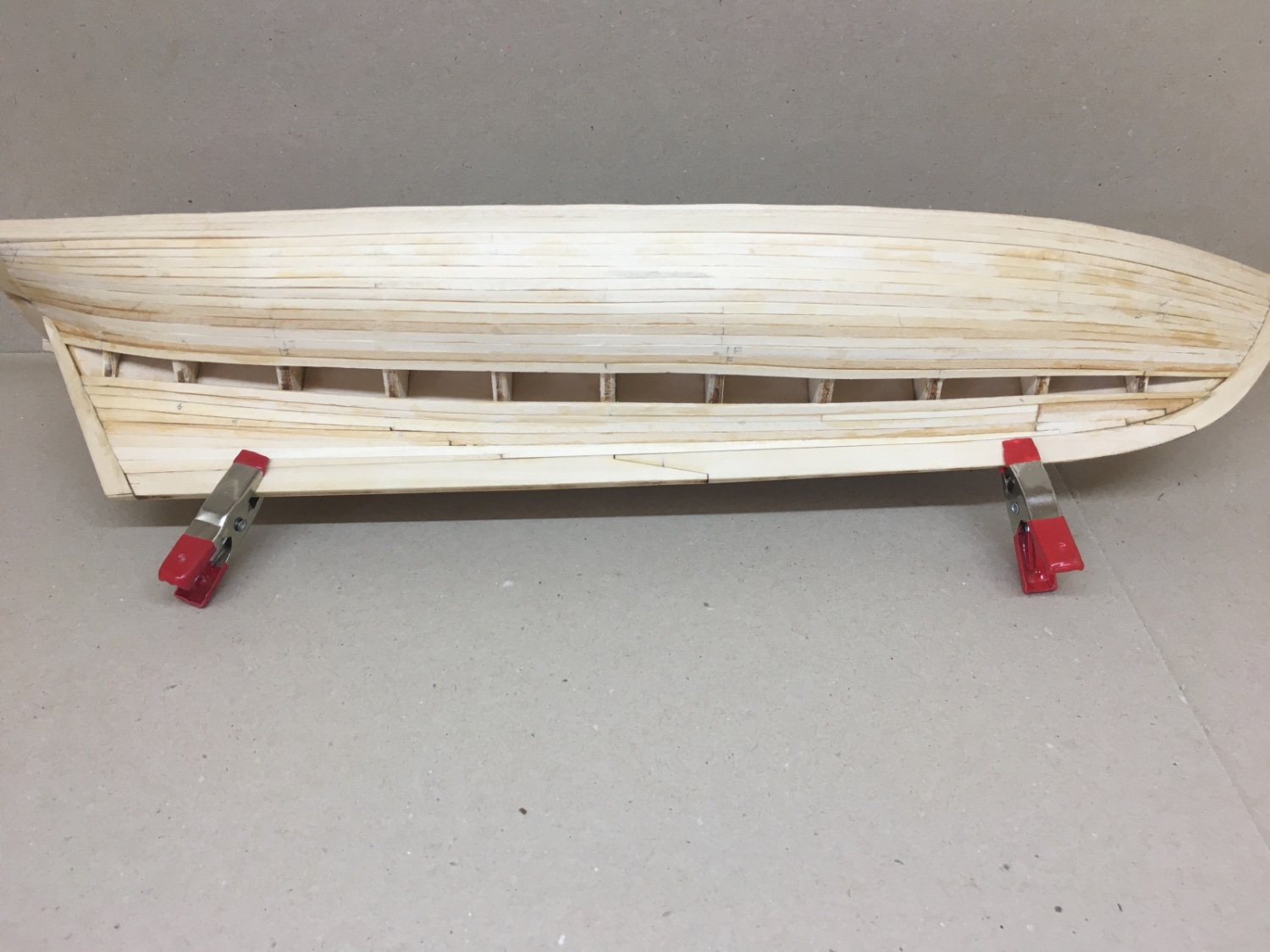
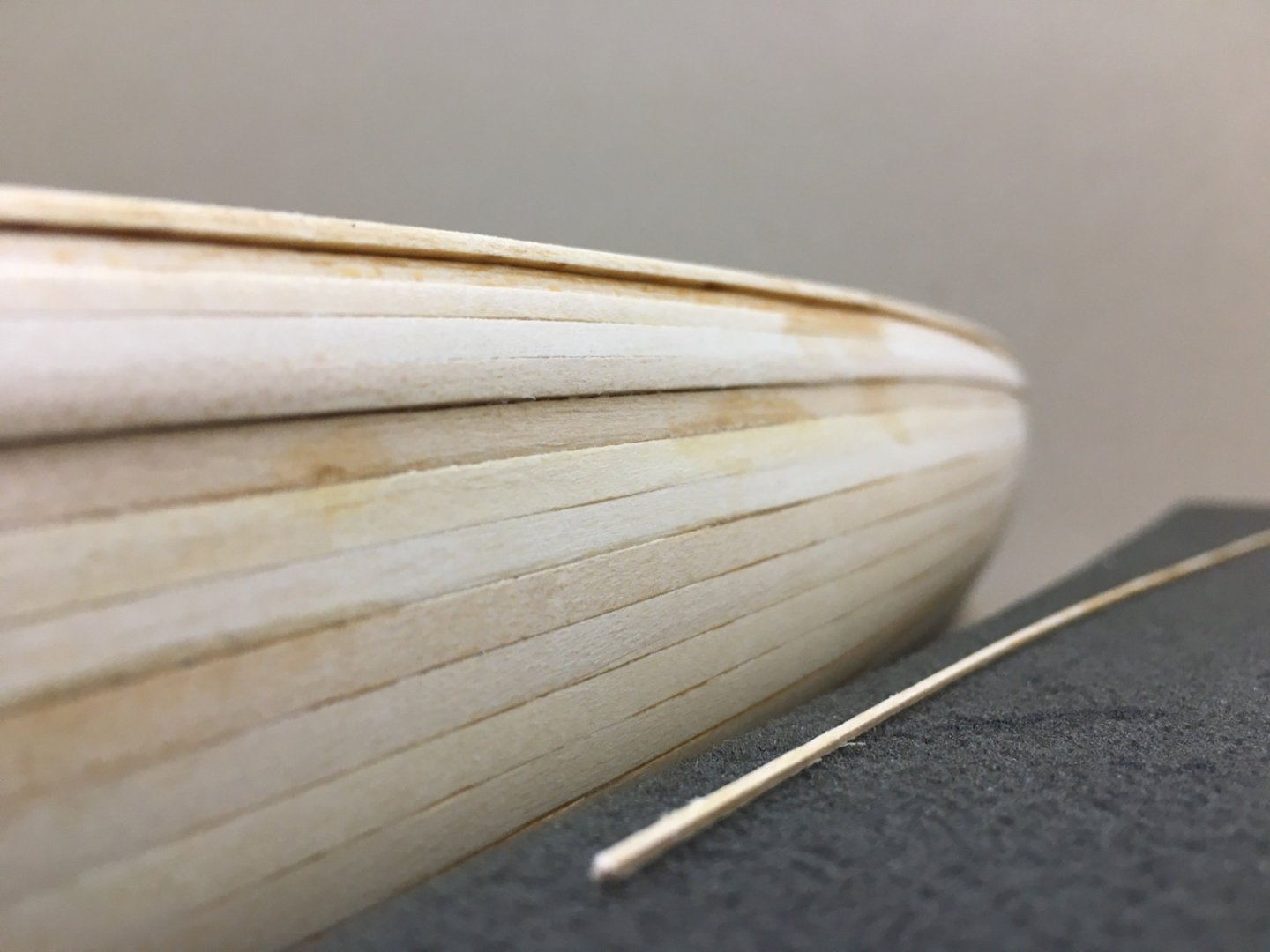
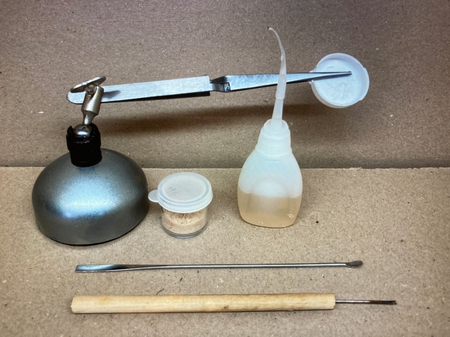
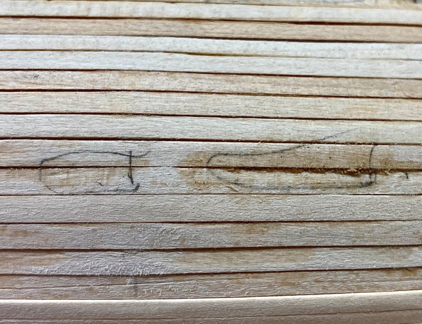
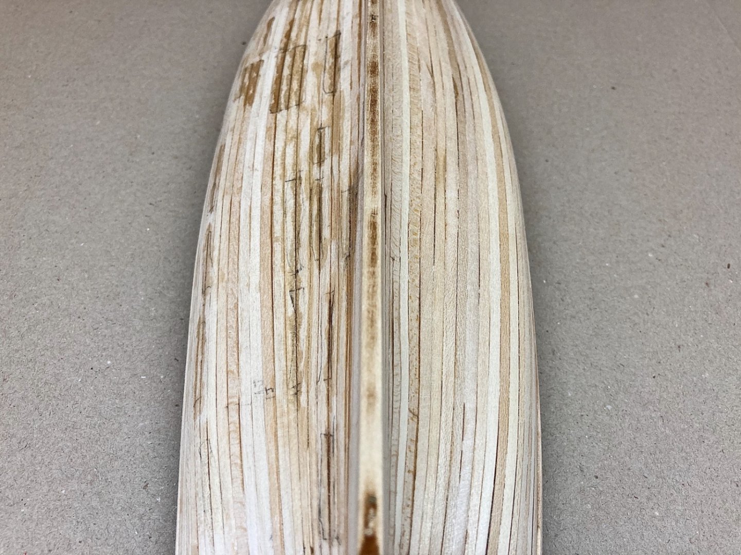
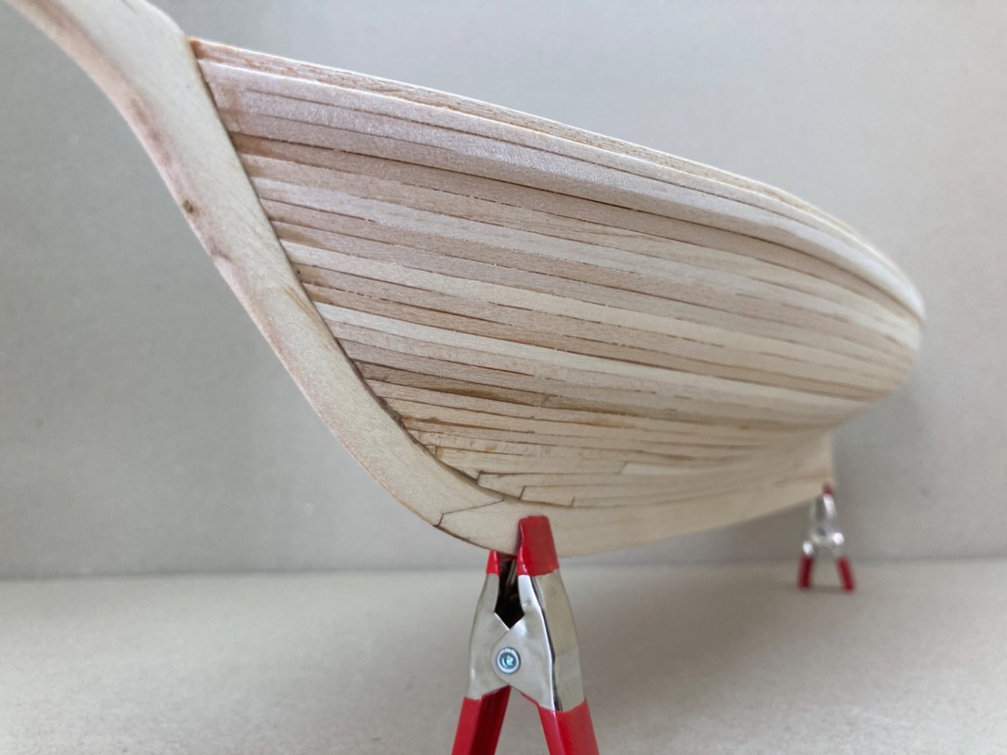
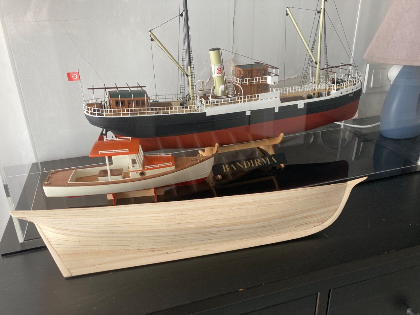
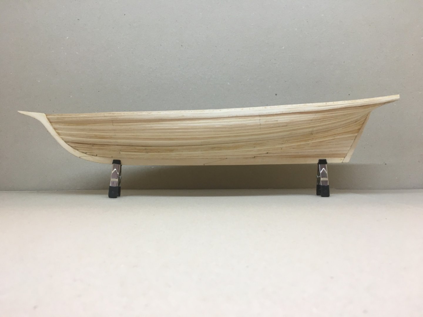
After the hull and counter planking was finished, comes the hull sanding step. Before I share the details at this stage, I like to explain how I ( and of course my fellow scale model mentor in Turkiye) handled the hull, in the previous two builds, before painting starts. First step is to look for gaps between the planks and mark them with pencil. The large ones are filled thin wood strips. For small ones I start filling them with saw or sanding dust collected before. Squeeze them with a suitable instrument and then apply thin , gap filling CA with a self-made glue applicator. If needed the procedure is repeated. For big and easily palpable grooves the same method is used. Then the sanding process begins starting with 120 or 150 grits and ending with 400 grit. Sanding is done with suitable sanding blocks prepared. Then comes the filling step. For filling and smoothening the surface I use sanding sealer. In fact if you translate the Turkish name of sanding sealer to English , which is ' Filling Varnish' , it is clear that the name is self-explanatory . Sanding sealer is applied with airbrush starting with 1:1 concentration with lacquer thinner. The number of coats change with the absorption characteristics of the wood applied. However, you dilute the concentration to 1:1.5 or even 1:2 in the final coats. If there are any grooves left, the undiluted sanding sealer is applied with a brush to those areas. For airbrush coats , after 4-6 hours , hull is sanded with 400 grit and the next coat is applied. For brush applied undiluted sanding sealer, waiting overnight is needed. The same procedure was followed in POB II also. Here are some pictures. Looking for gaps by holding a light source behind and marking them. Instrument set up for this procedure Filled gap example After all the gaps are handled came the sanding step. Sanding was done using the prepared sanding blocks and done patiently with checking after every 4-5 moves in order not to take away plank wood more than necessary (believe me I penetrated the hull in my first build by harsh sanding). Also I took care not to use soft ones in sharp bordered areas. 1: PVC foam based 2. Commercial sanding blocks 3. Wood block based 4. Commercial sanding sticks 5. Sponge based Here are some pictures after sanding Sanding started with port side Starboard side Other angles Here are some pictures after sanding with the final 400 grit sanding. Comparison of the model with the previous two builds. The big one is 'Panderma' by Turkmodel and The Lobster Boat 'Sunrise' is by KG Models.


- 114 replies
-
- 6
-
-

-
- Pride of Baltimore II
- Model Shipways
- (and 1 more)
-
Yves and Kevin, Thanks a lot for your comments. Kevin , I am glad to be helpful.
- 114 replies
-
- 1
-
-
- Pride of Baltimore II
- Model Shipways
- (and 1 more)
-
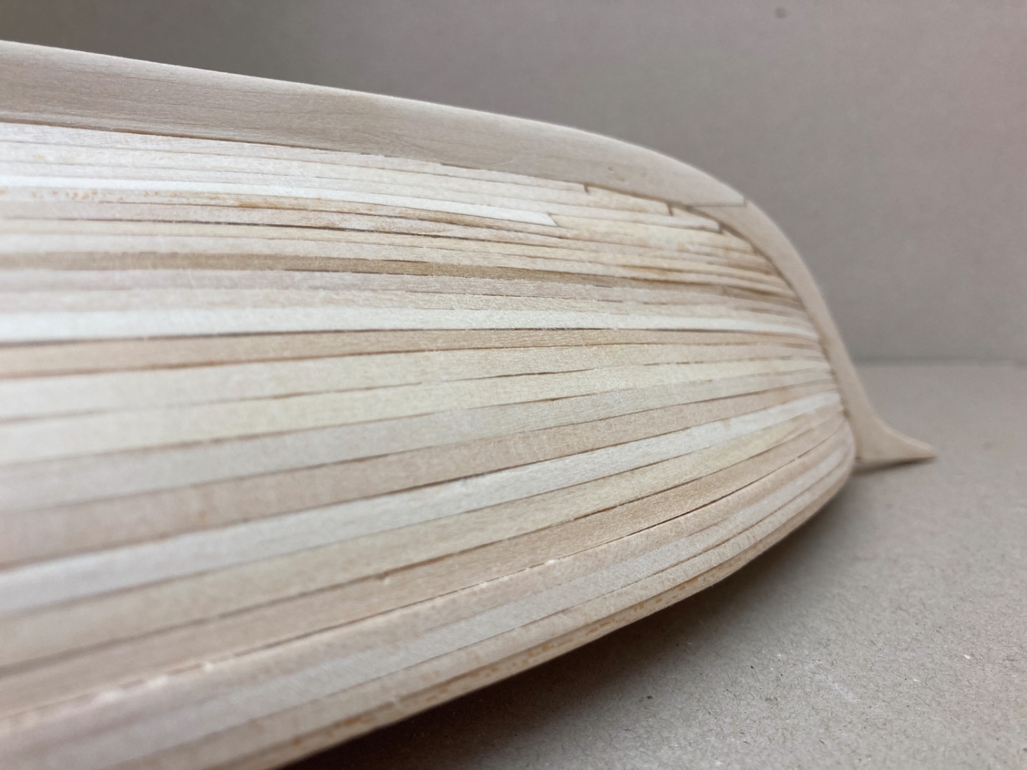
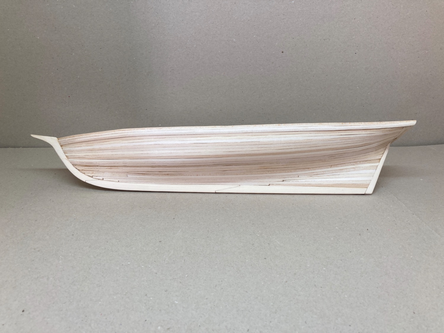
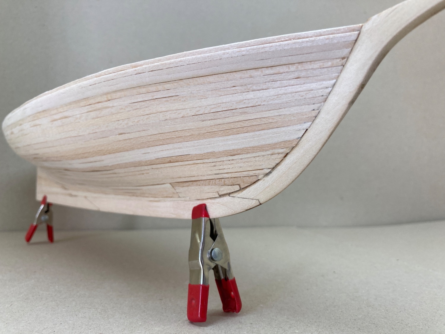
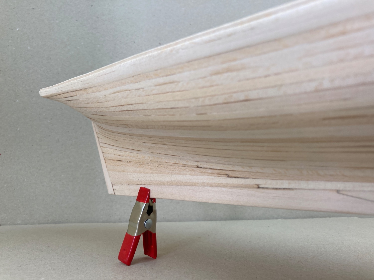
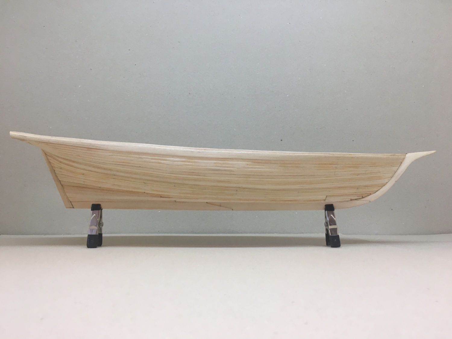
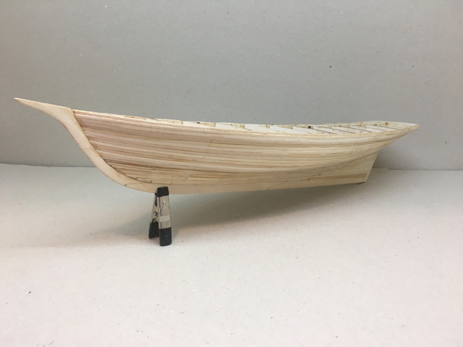
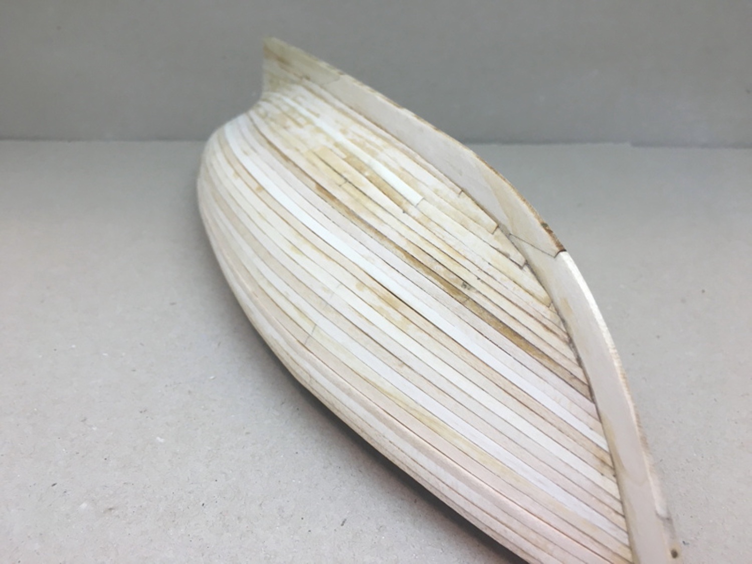
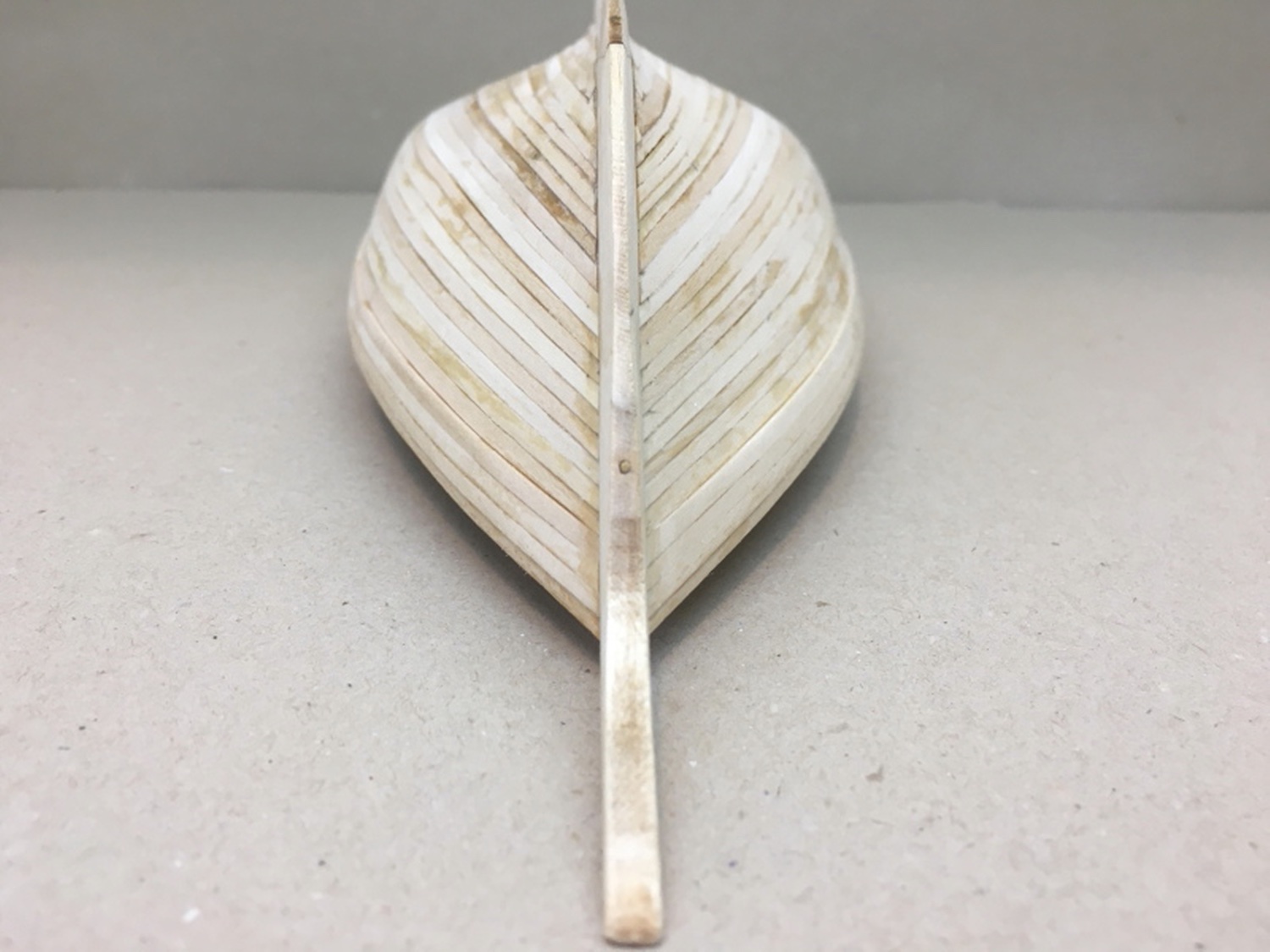
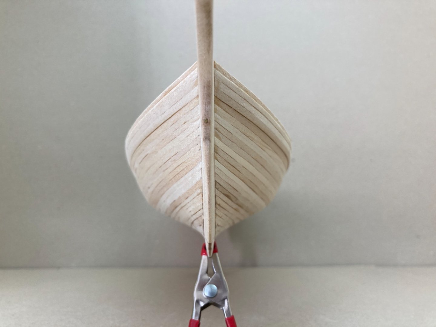
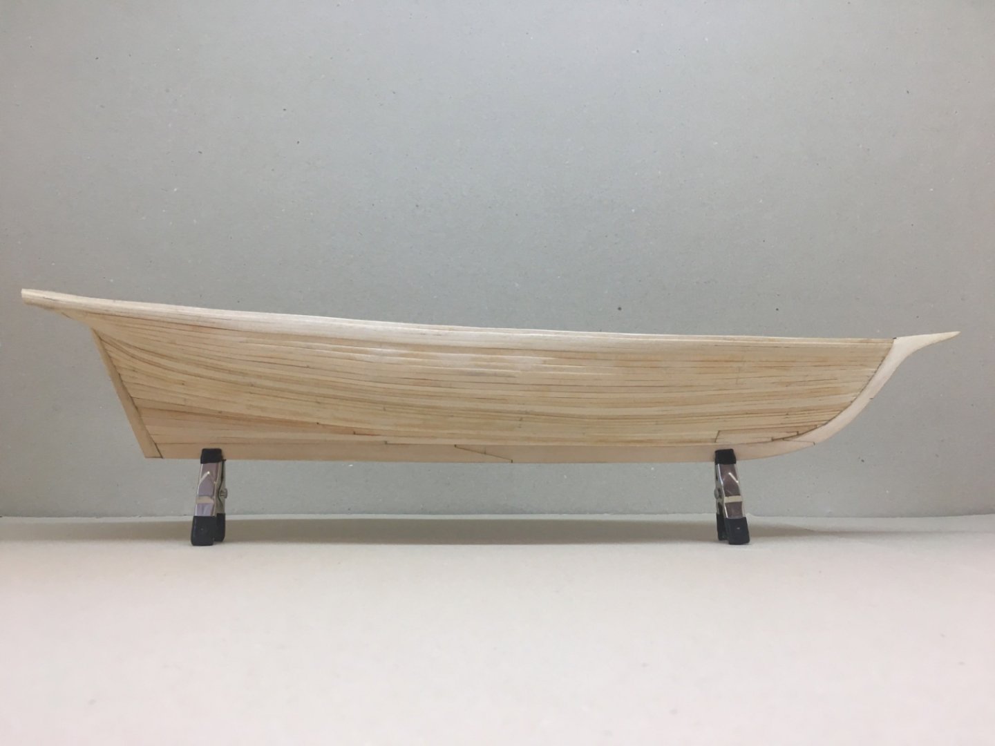
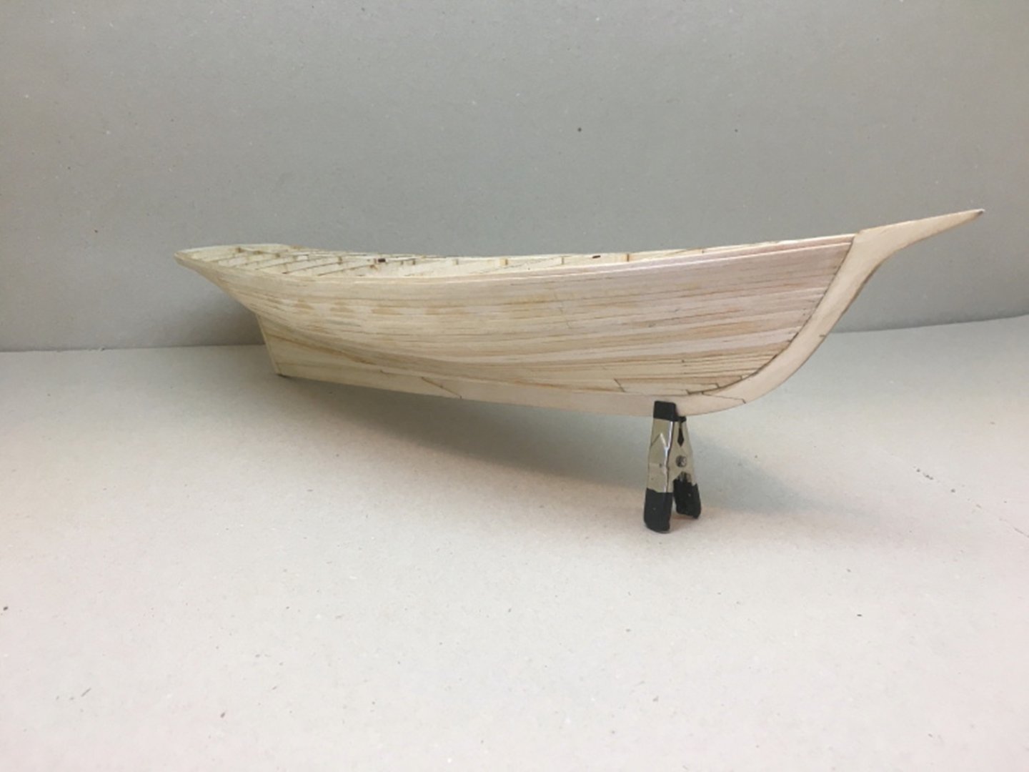
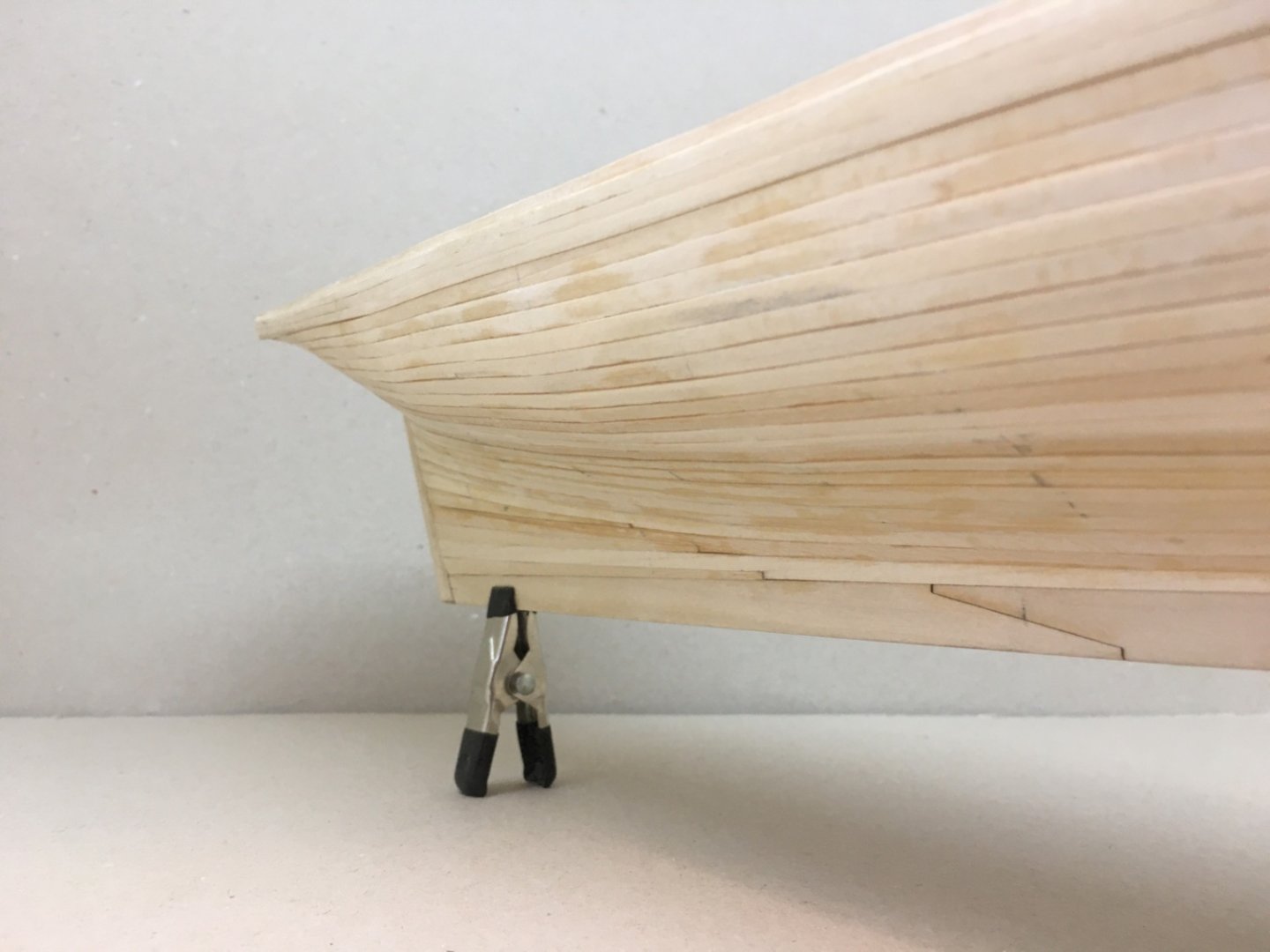
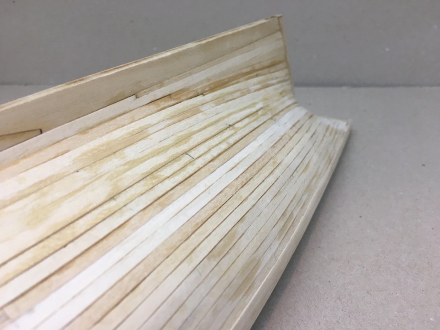
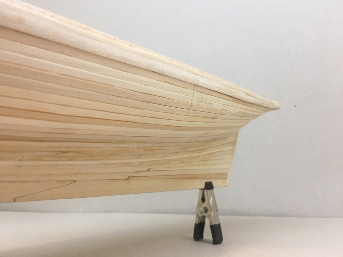
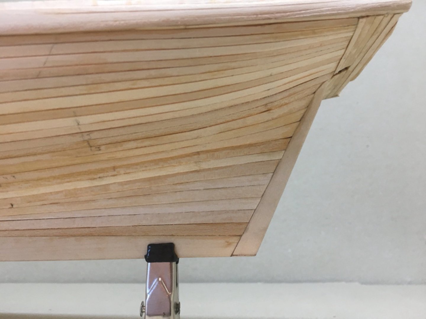
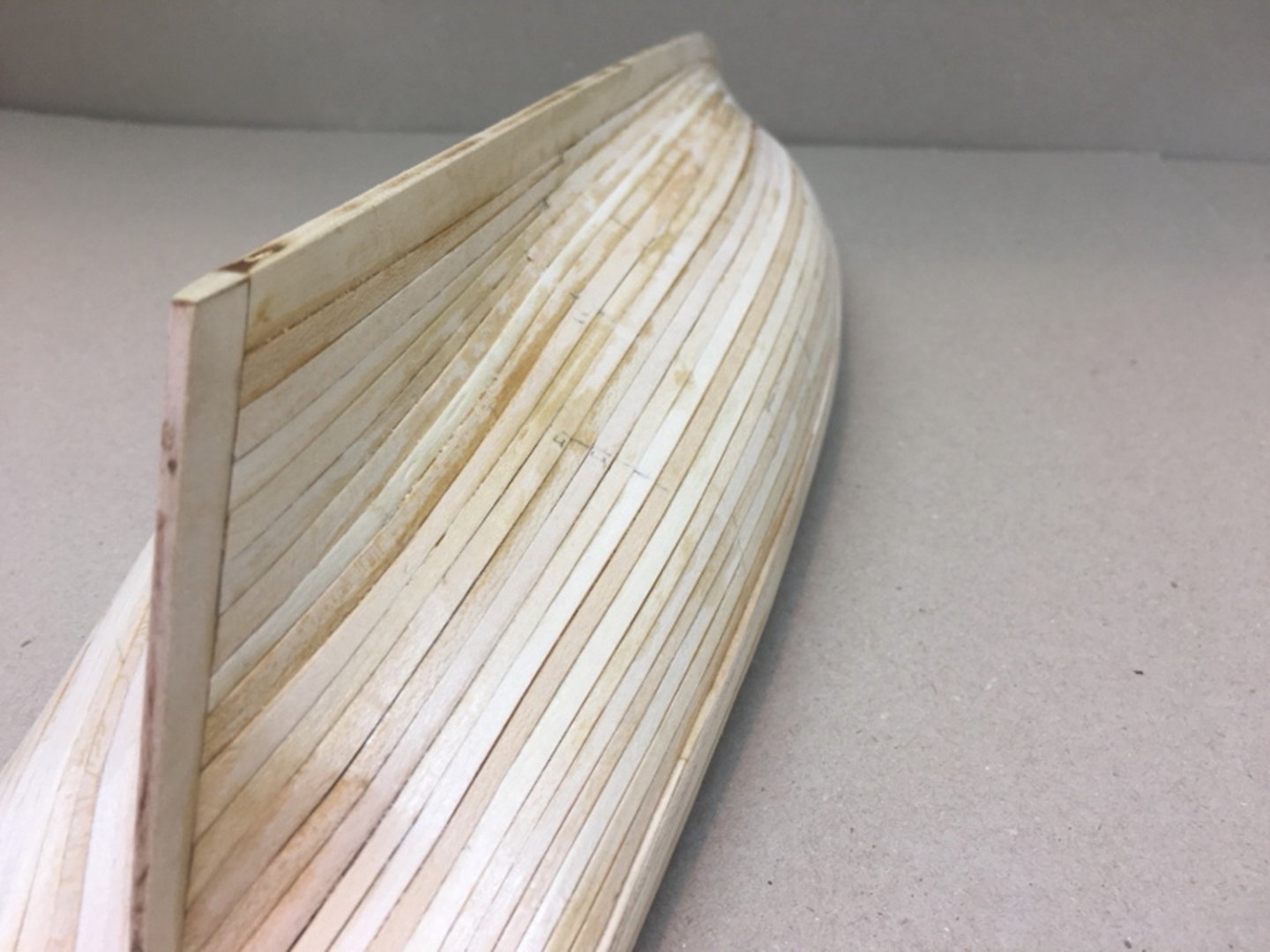
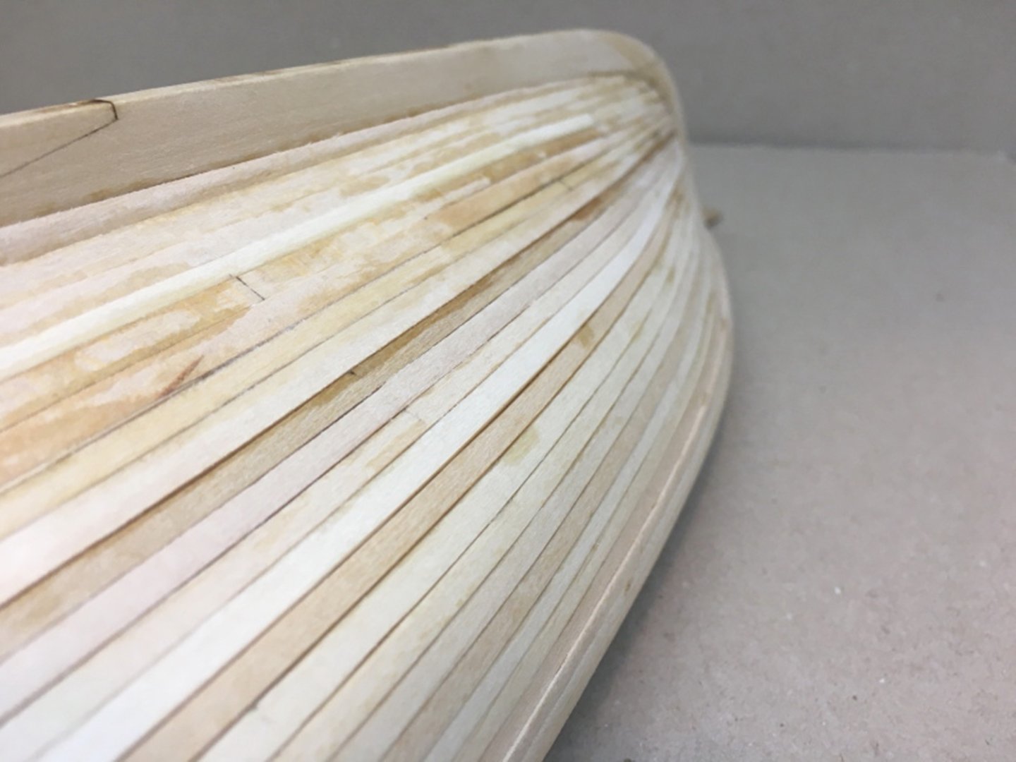
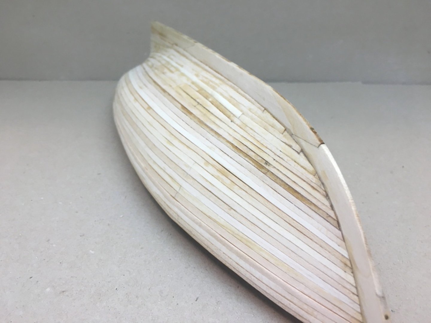
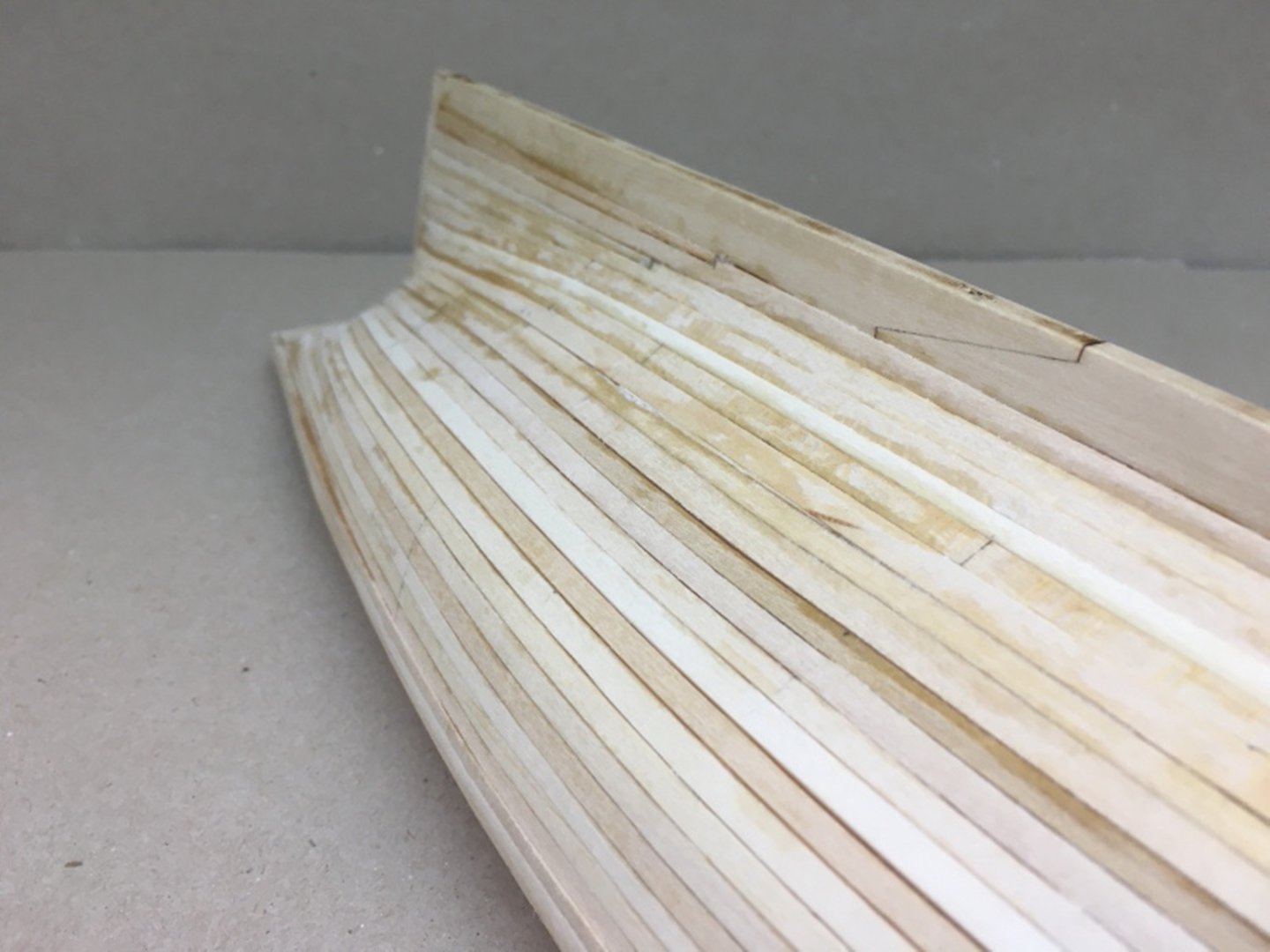
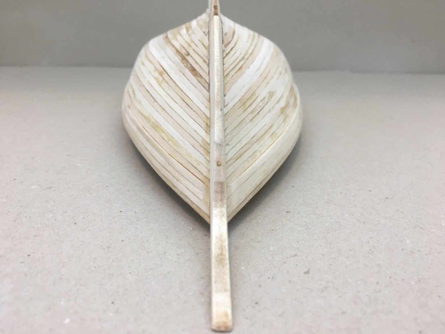
After planking the counter here are pictures of the hull . Starboard side Port side Other angles


- 114 replies
-
- 3
-
-
- Pride of Baltimore II
- Model Shipways
- (and 1 more)
-
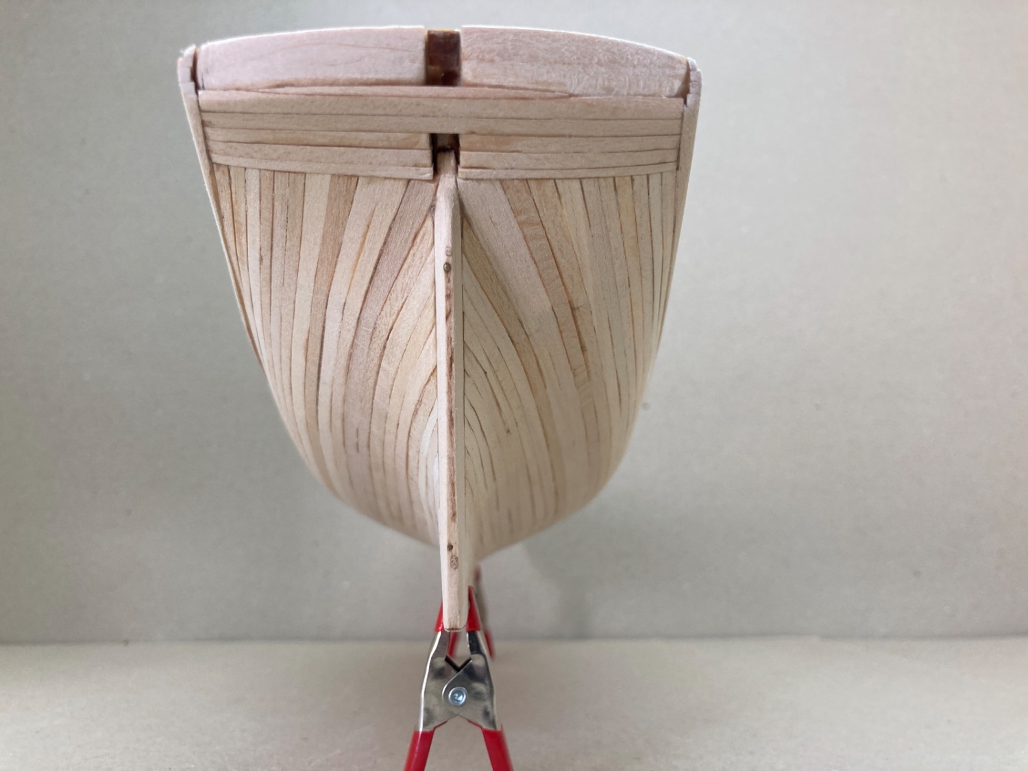
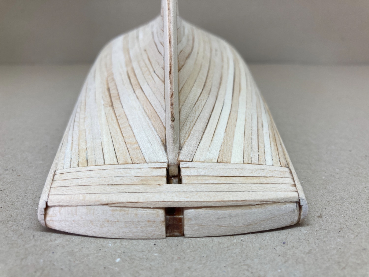
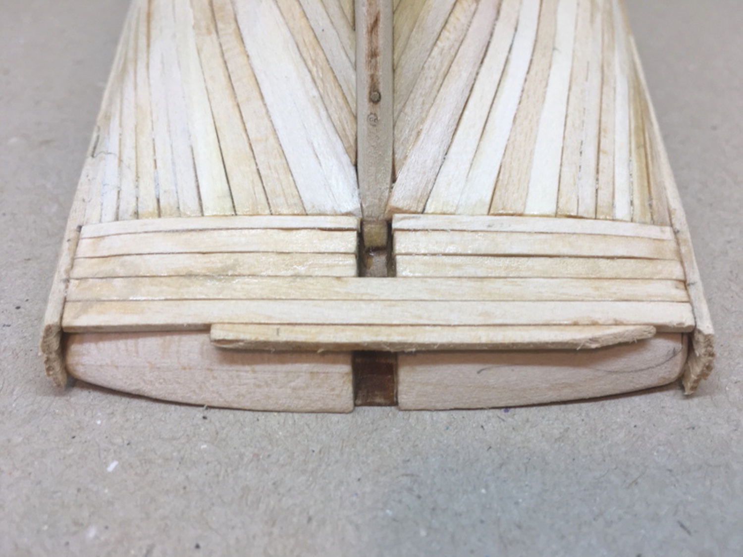
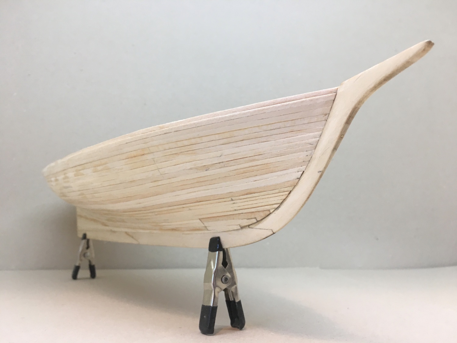
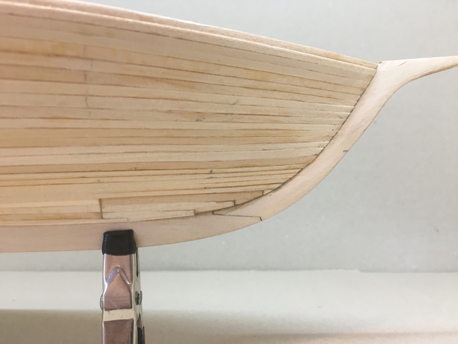
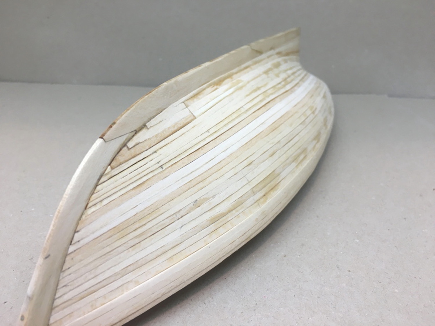
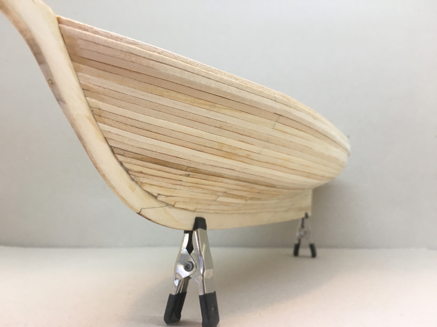
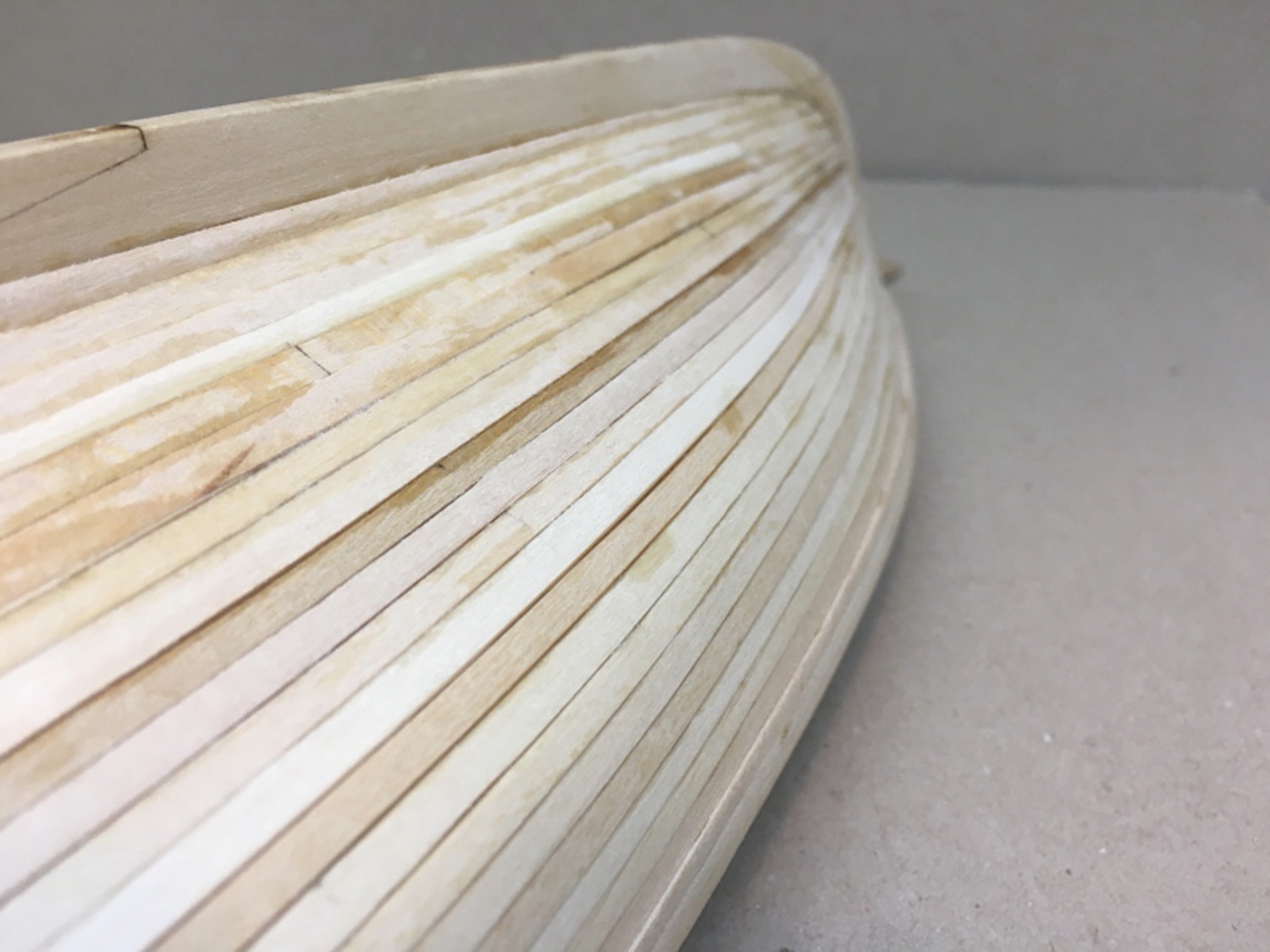
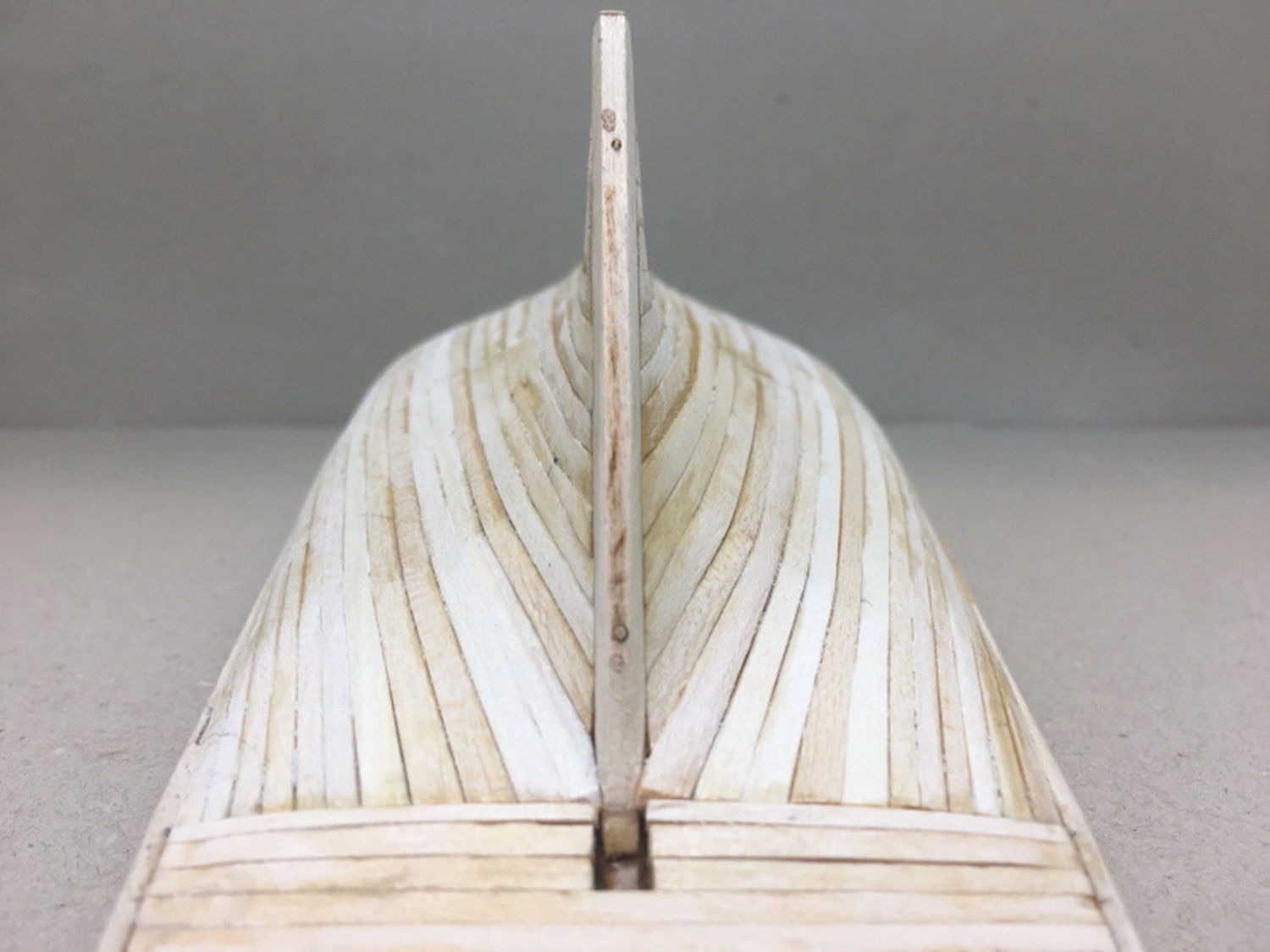
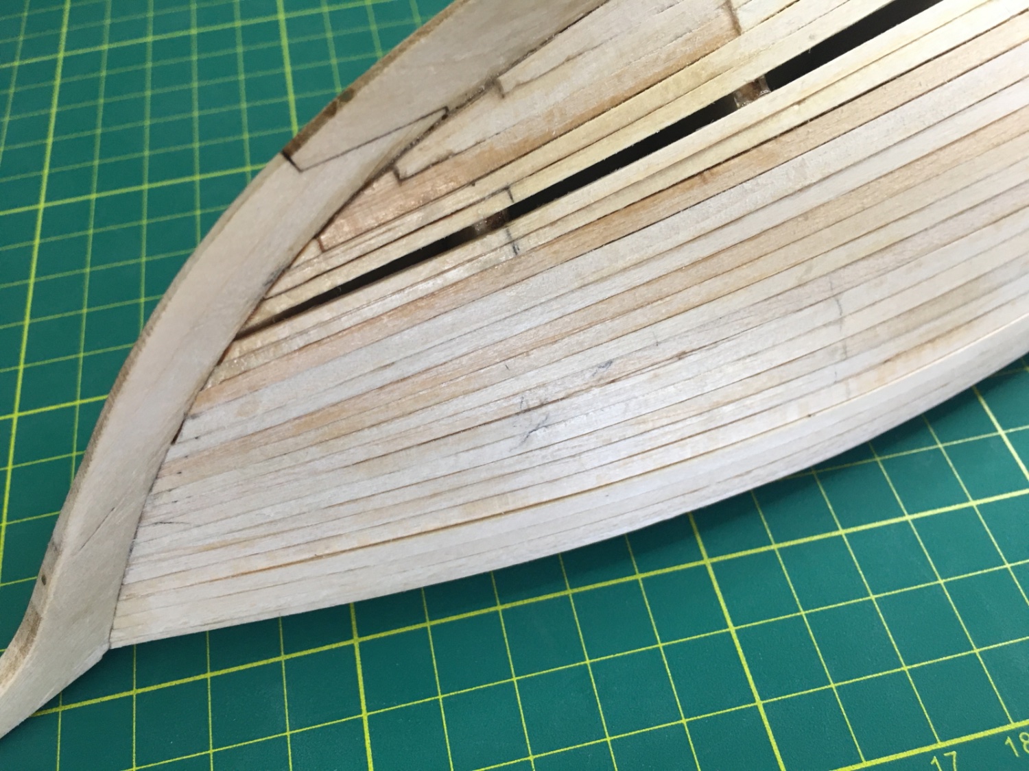
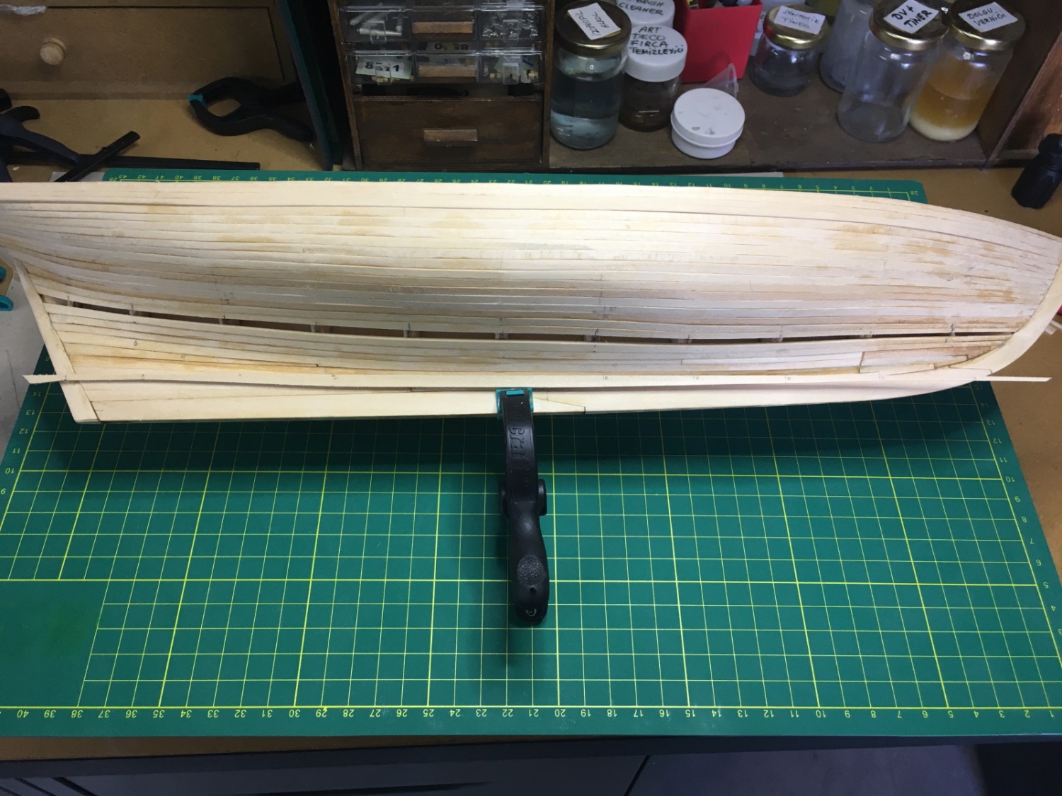
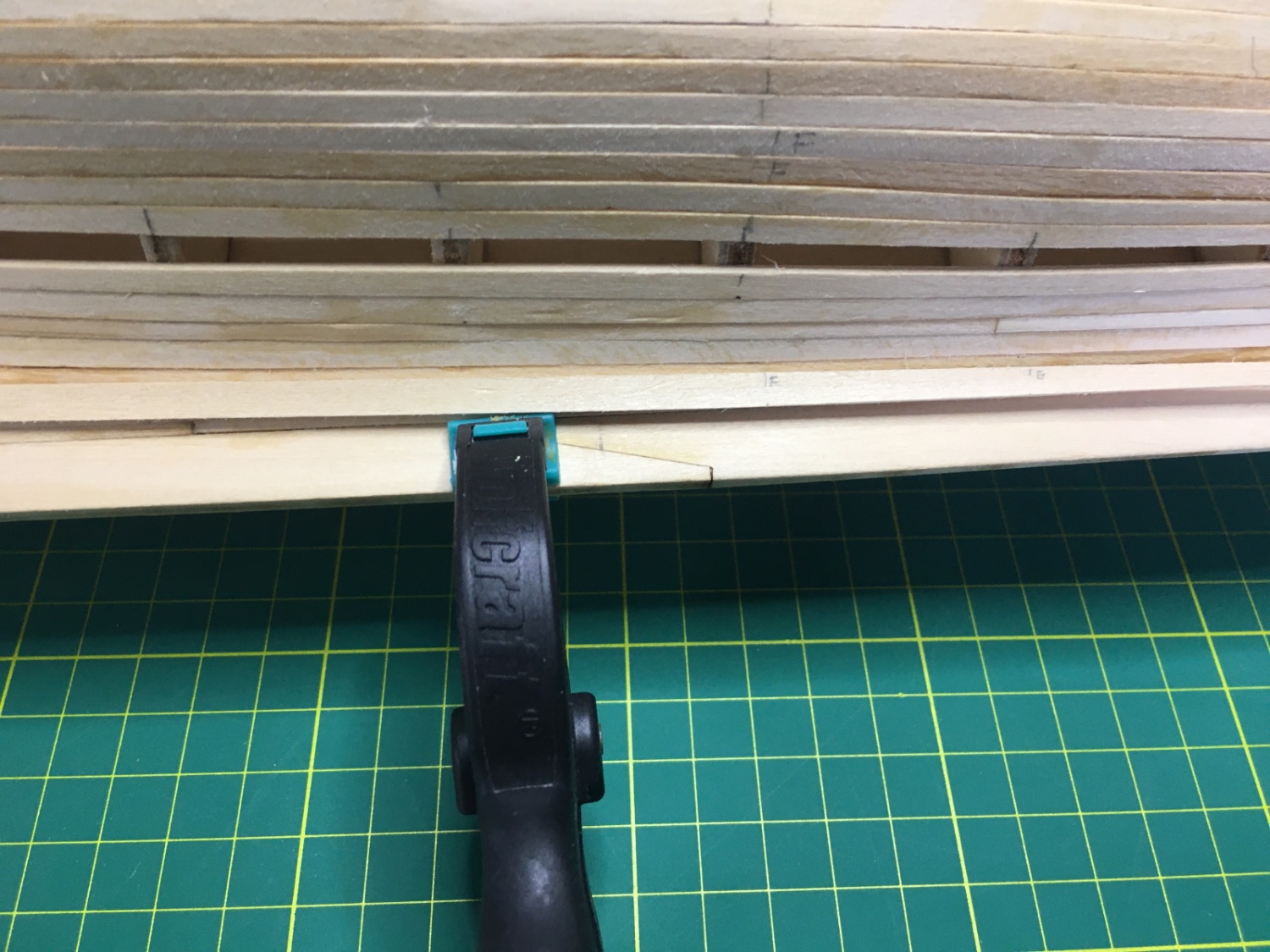
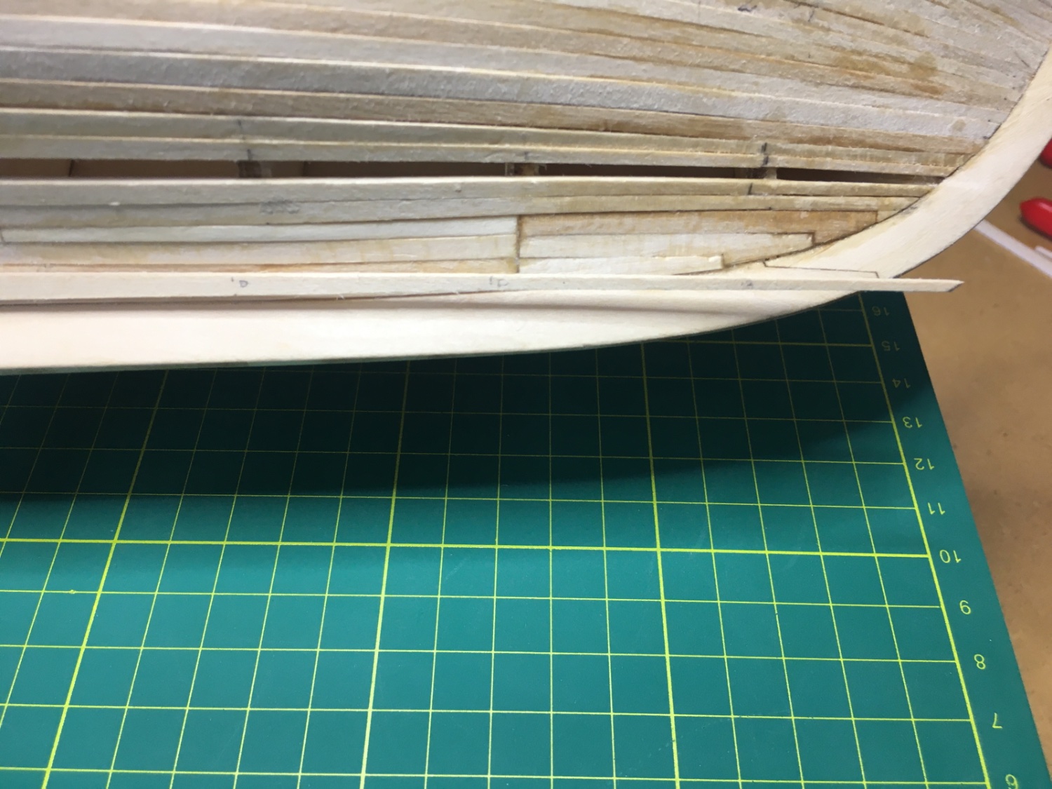
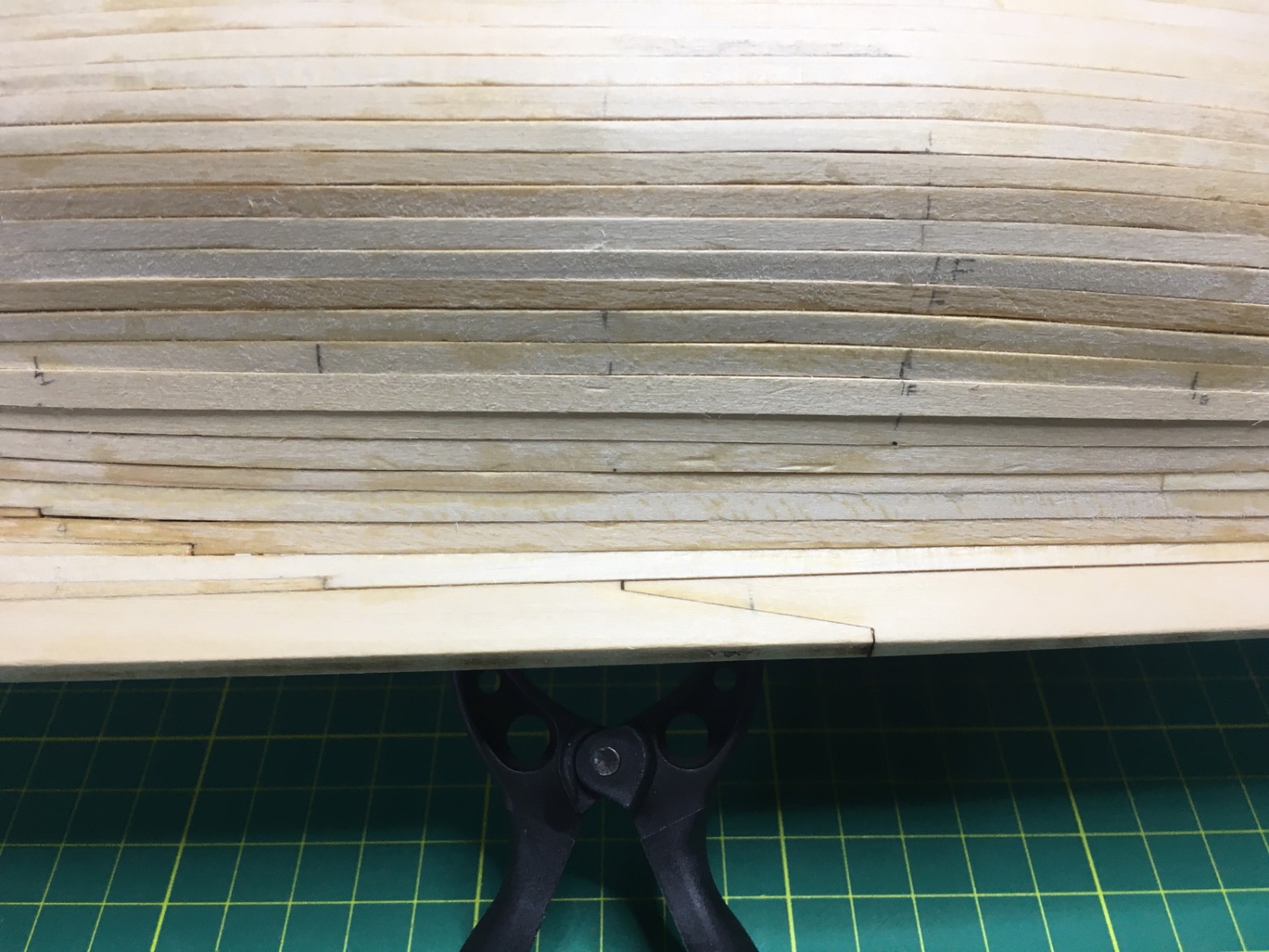
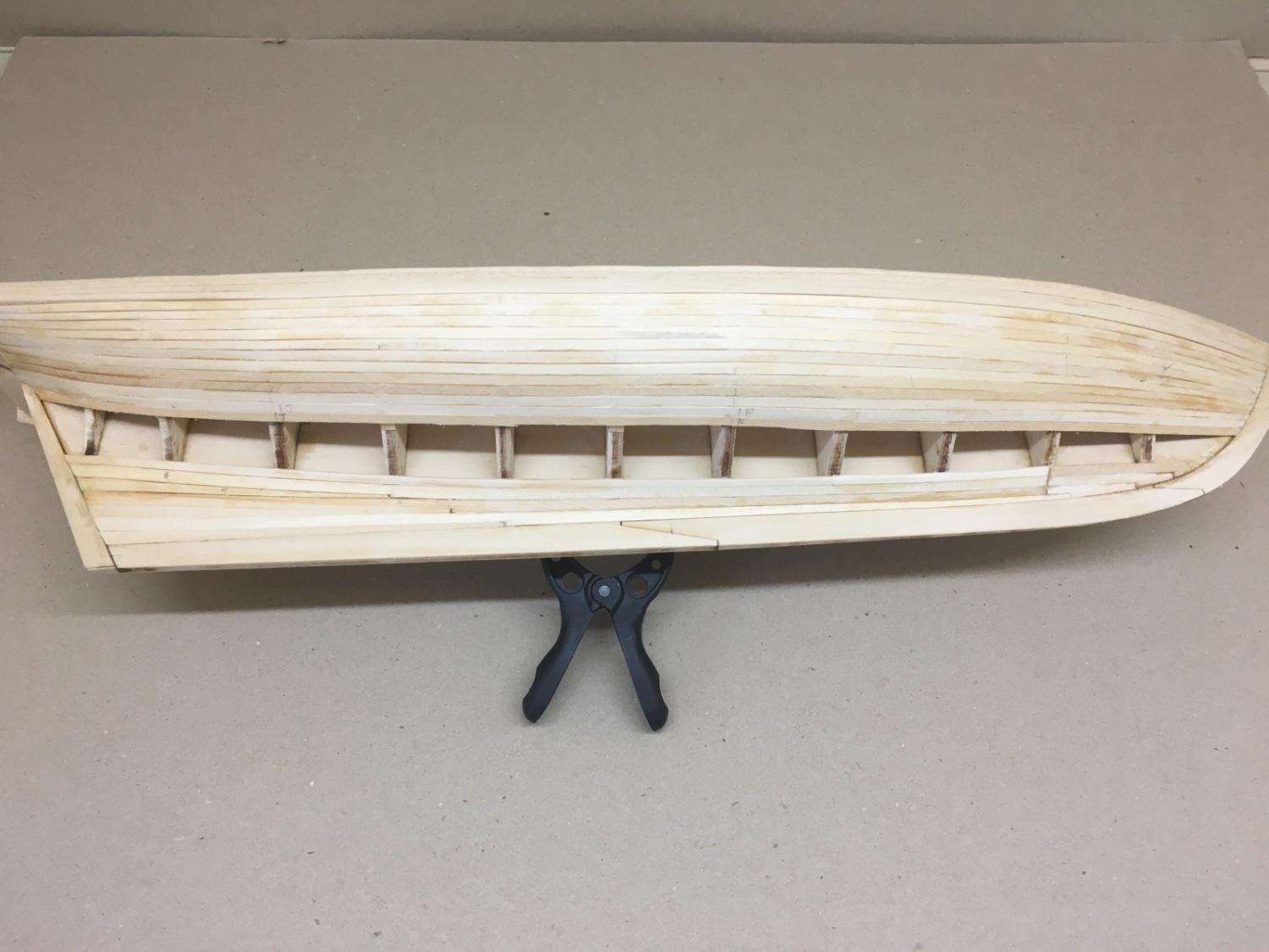
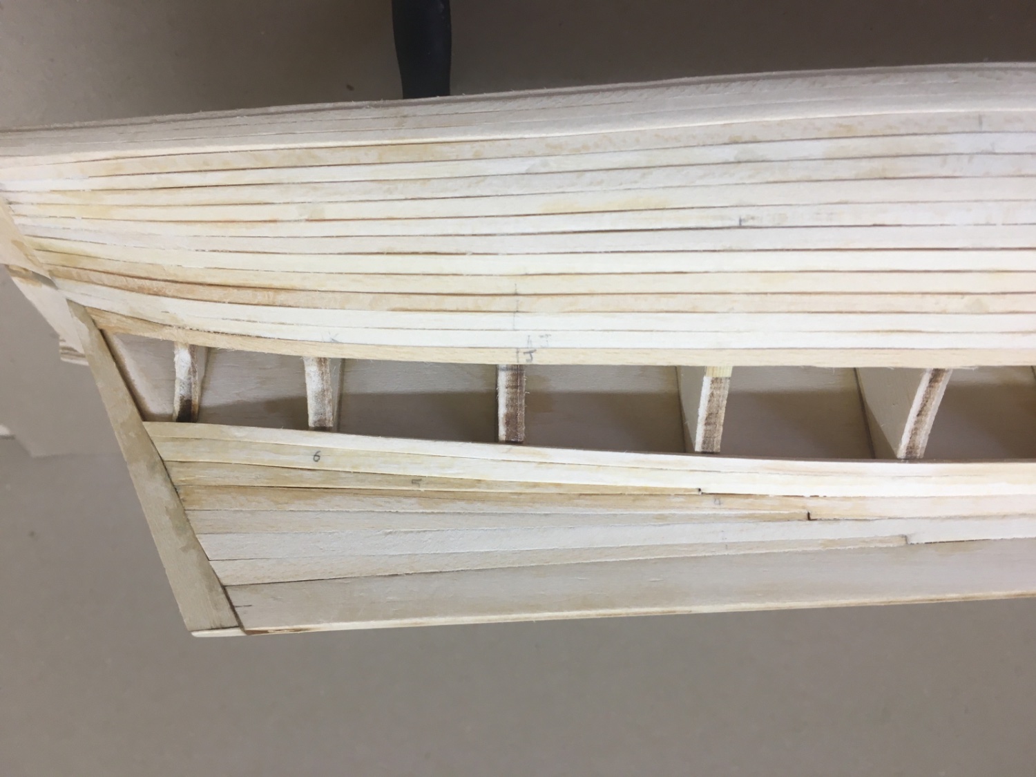
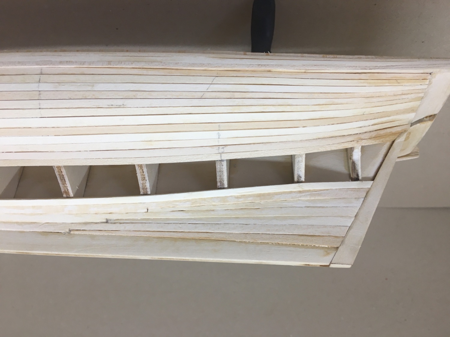
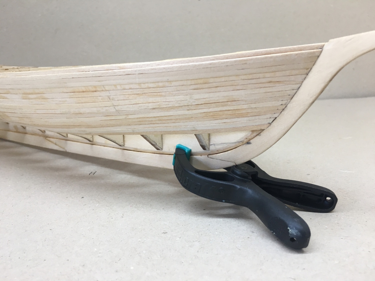
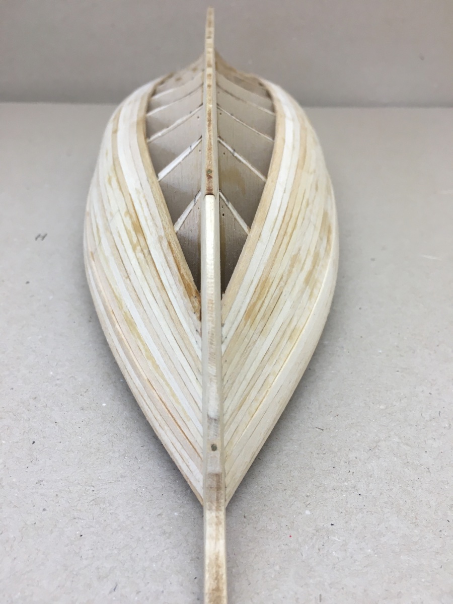
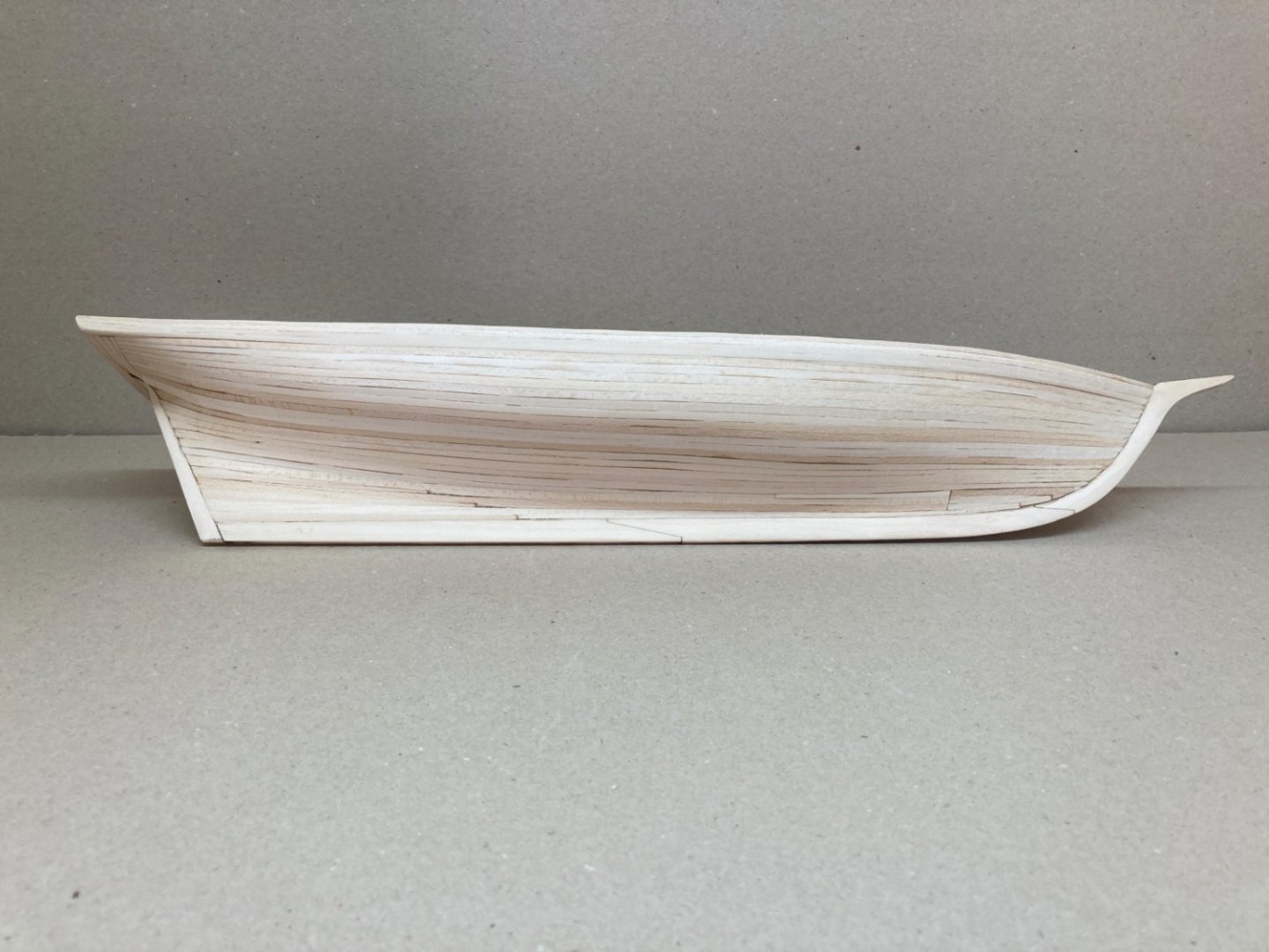
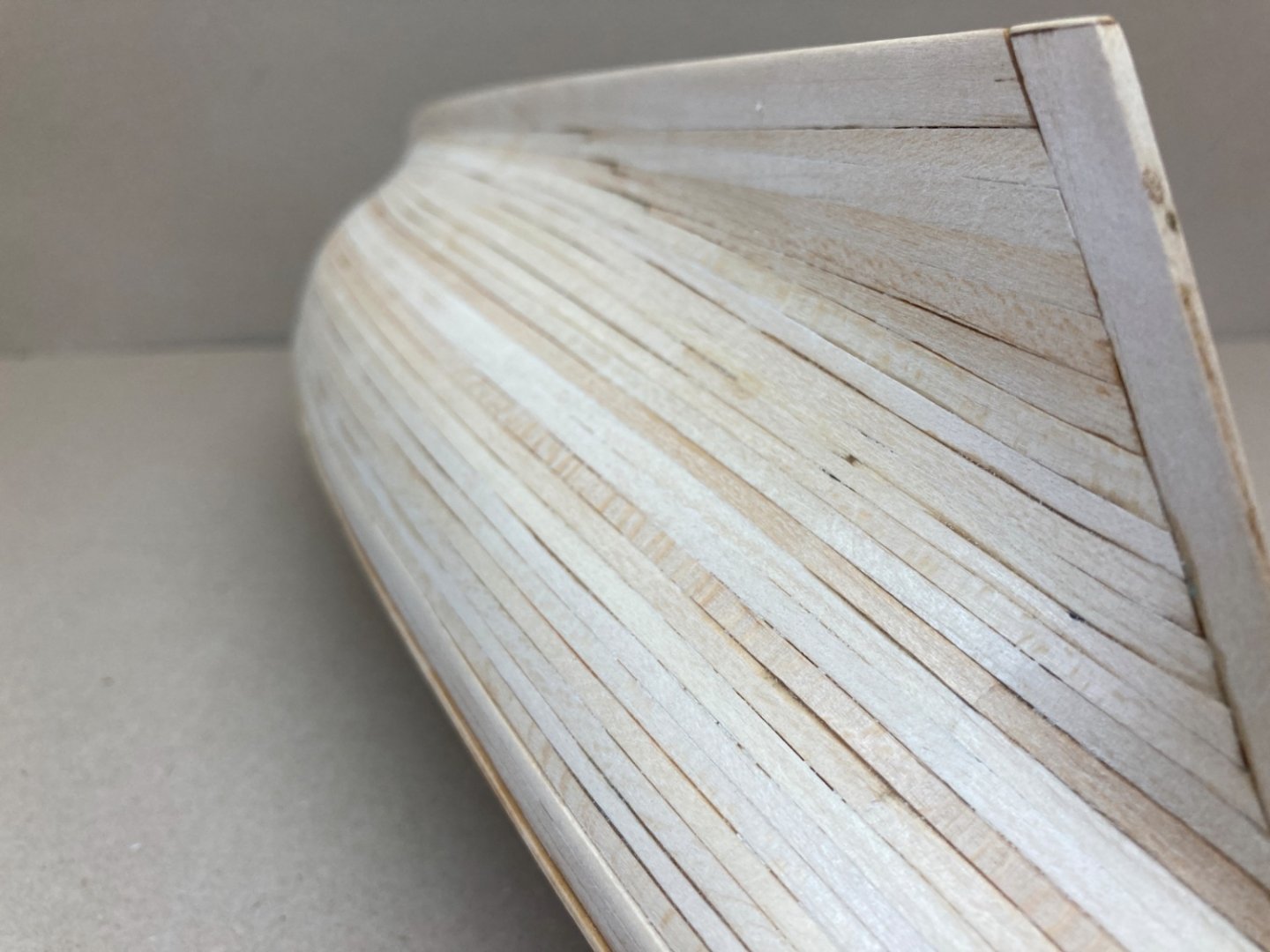
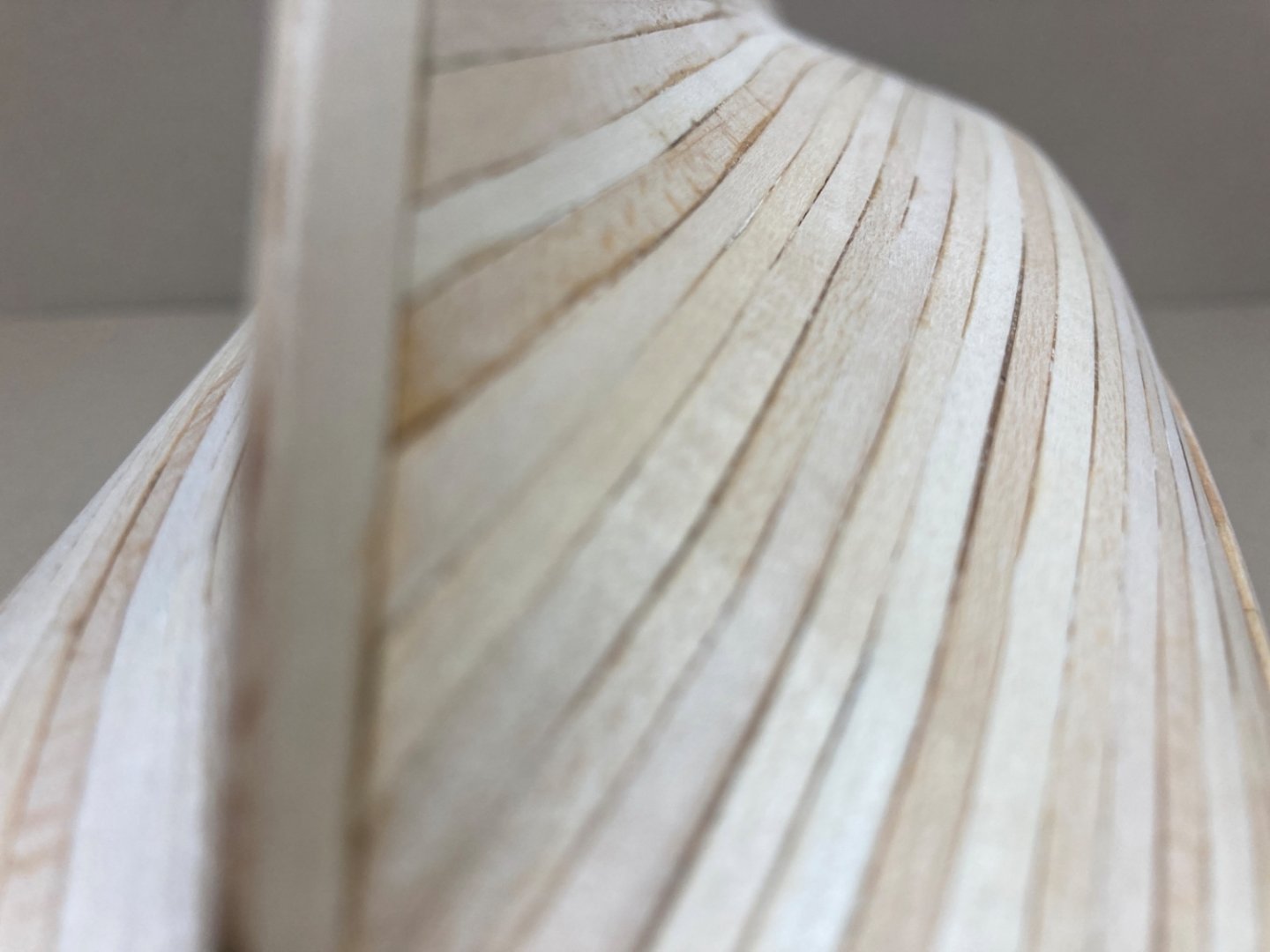
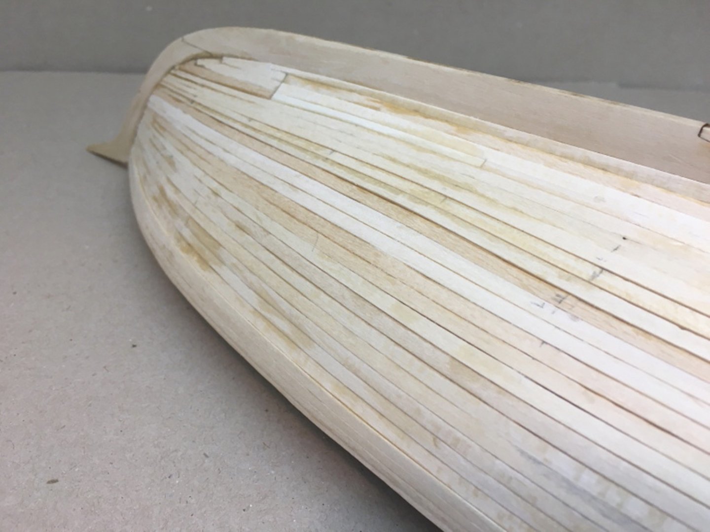
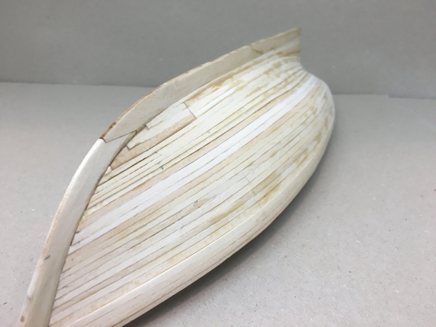
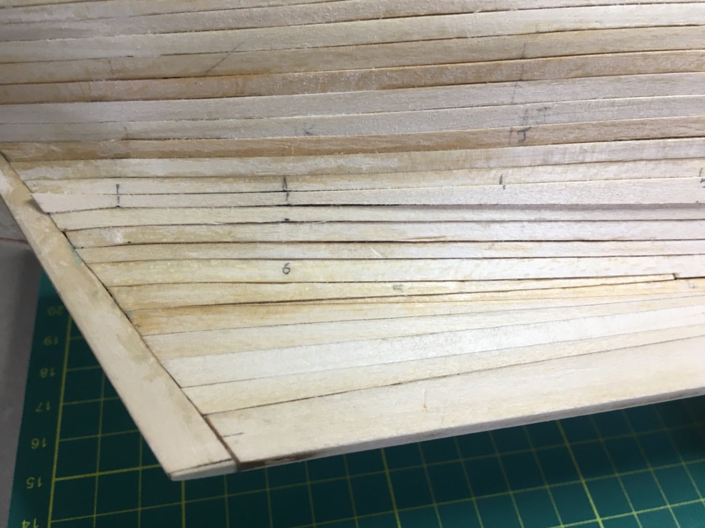
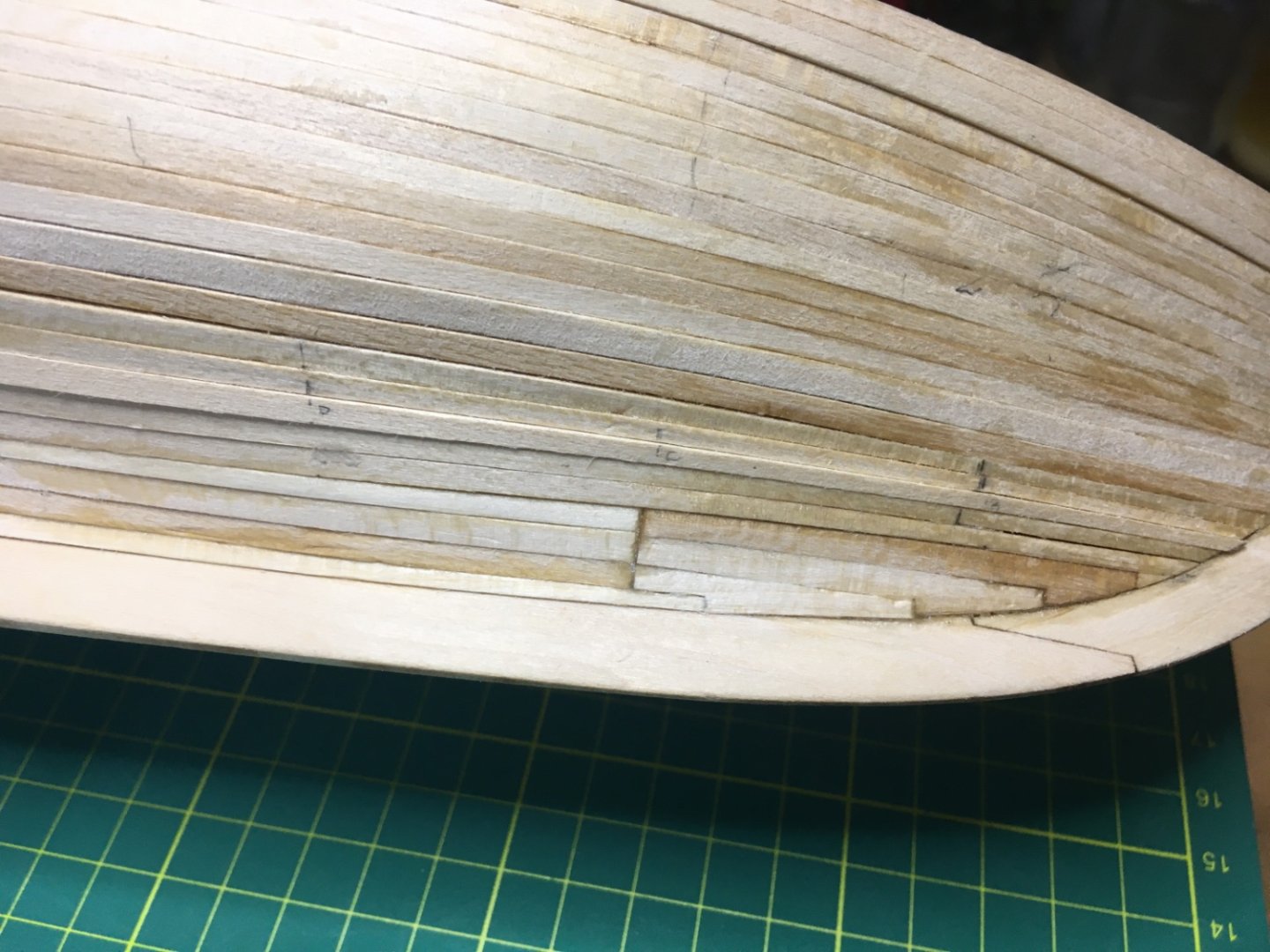
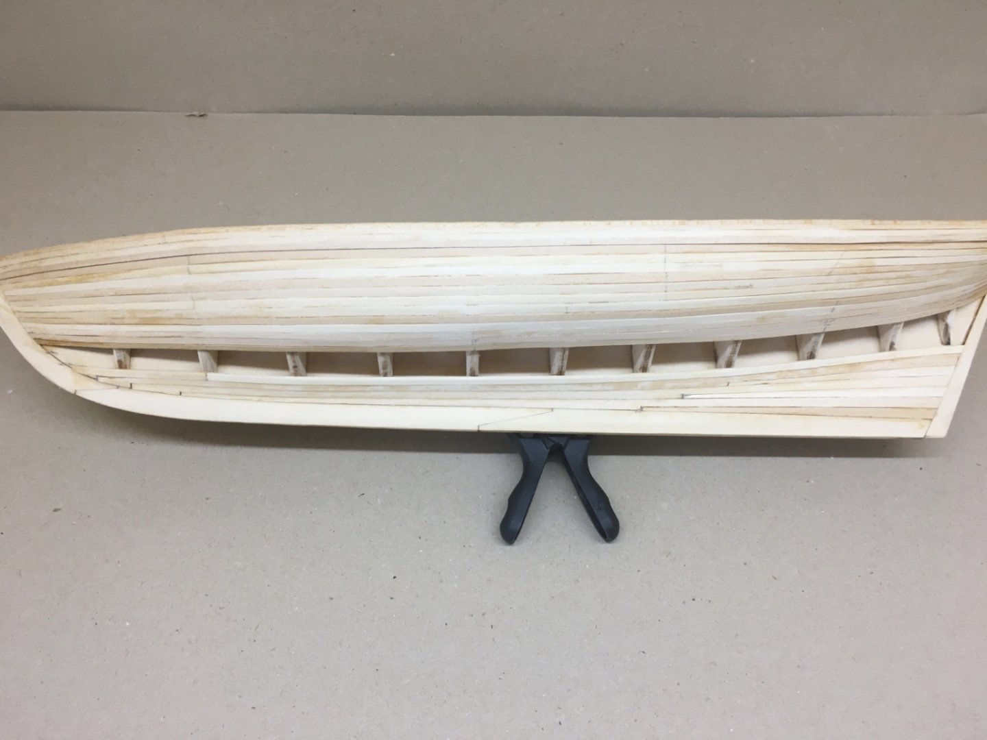
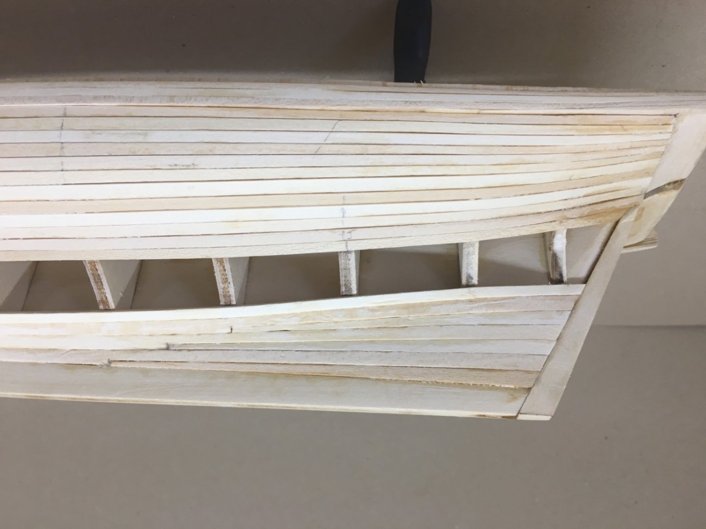
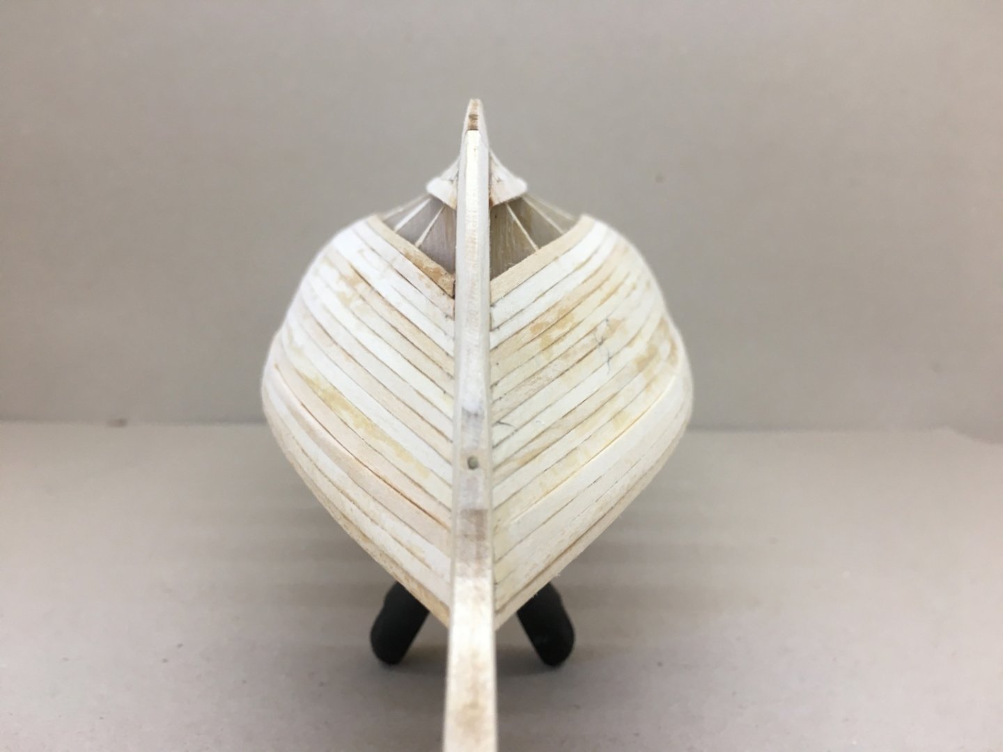
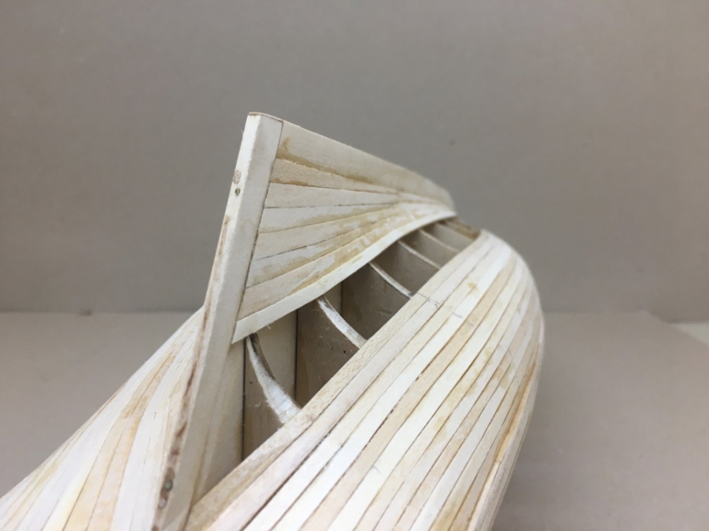
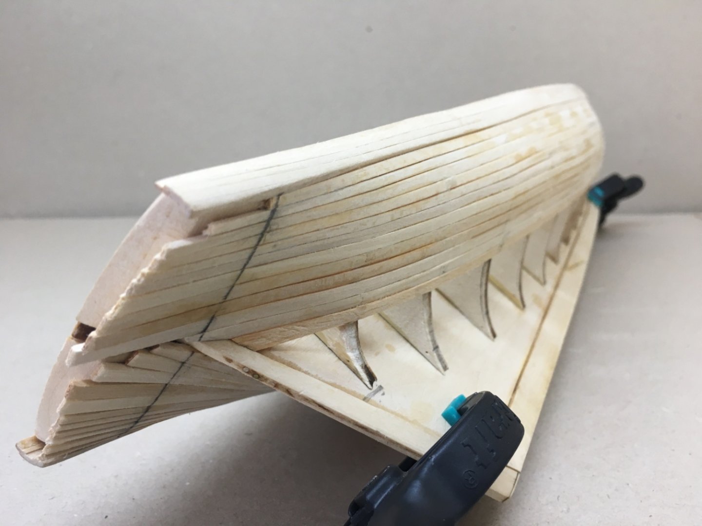
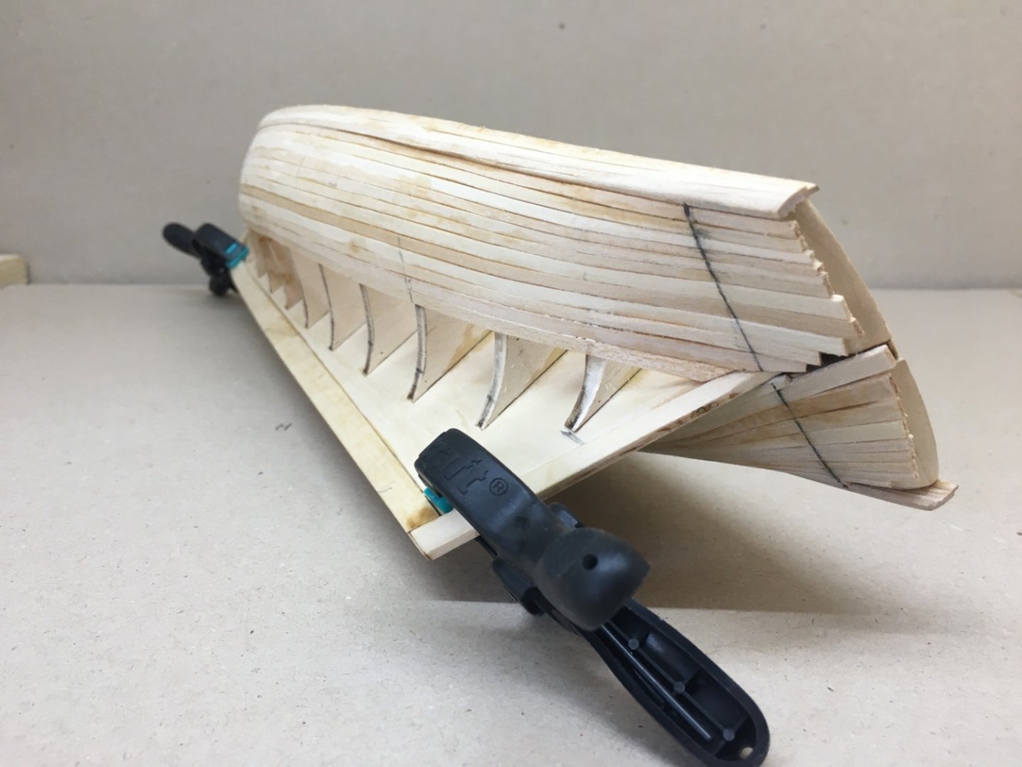
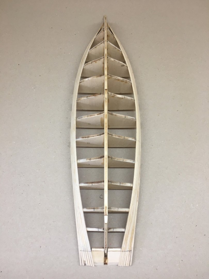
Final zone C needed new calculations as expected and proved to be right choice to leave to last. I had to take new measurements at each bulkhead and ended up with 5 rows on starboard and 4 rows on port sides. Every plank in this stage needed marking new measurements at each bulkhead and tapered referring to them. I started with starboard side. I installed a plank on deck and keel sides each. Taking the measurements of the remaining space again I prepared and installed two more planks, one on each deck and keel sides leaving a space between for the final plank. I prepared the last plank and dry fitted it at first to check the coverage . Dry fitting After dry fitting the plank was installed. The port side zone C planking is completed with the same manner. Starboard side Port side So the planking of the hull was finished.


- 114 replies
-
- 3
-
-
- Pride of Baltimore II
- Model Shipways
- (and 1 more)
-
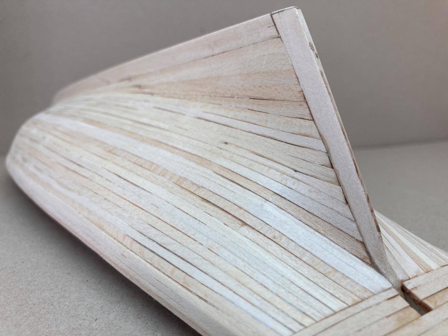
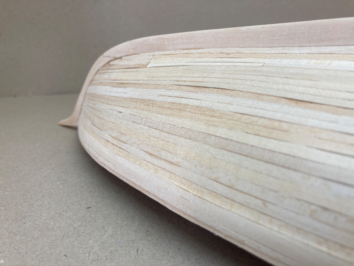
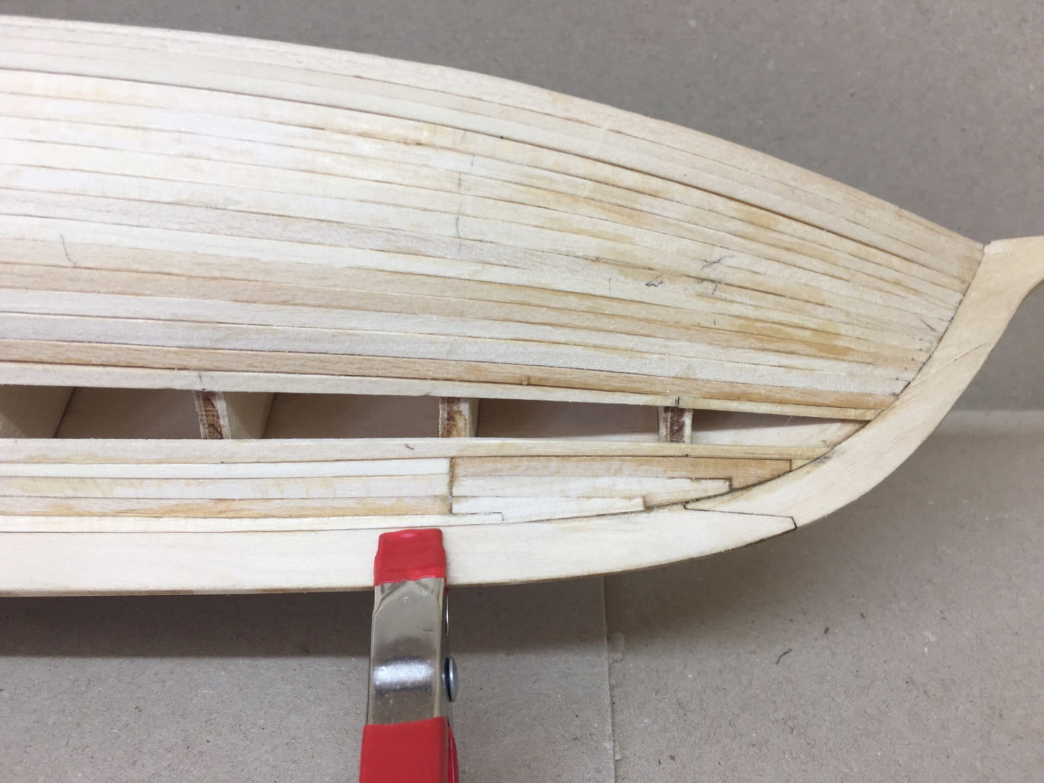
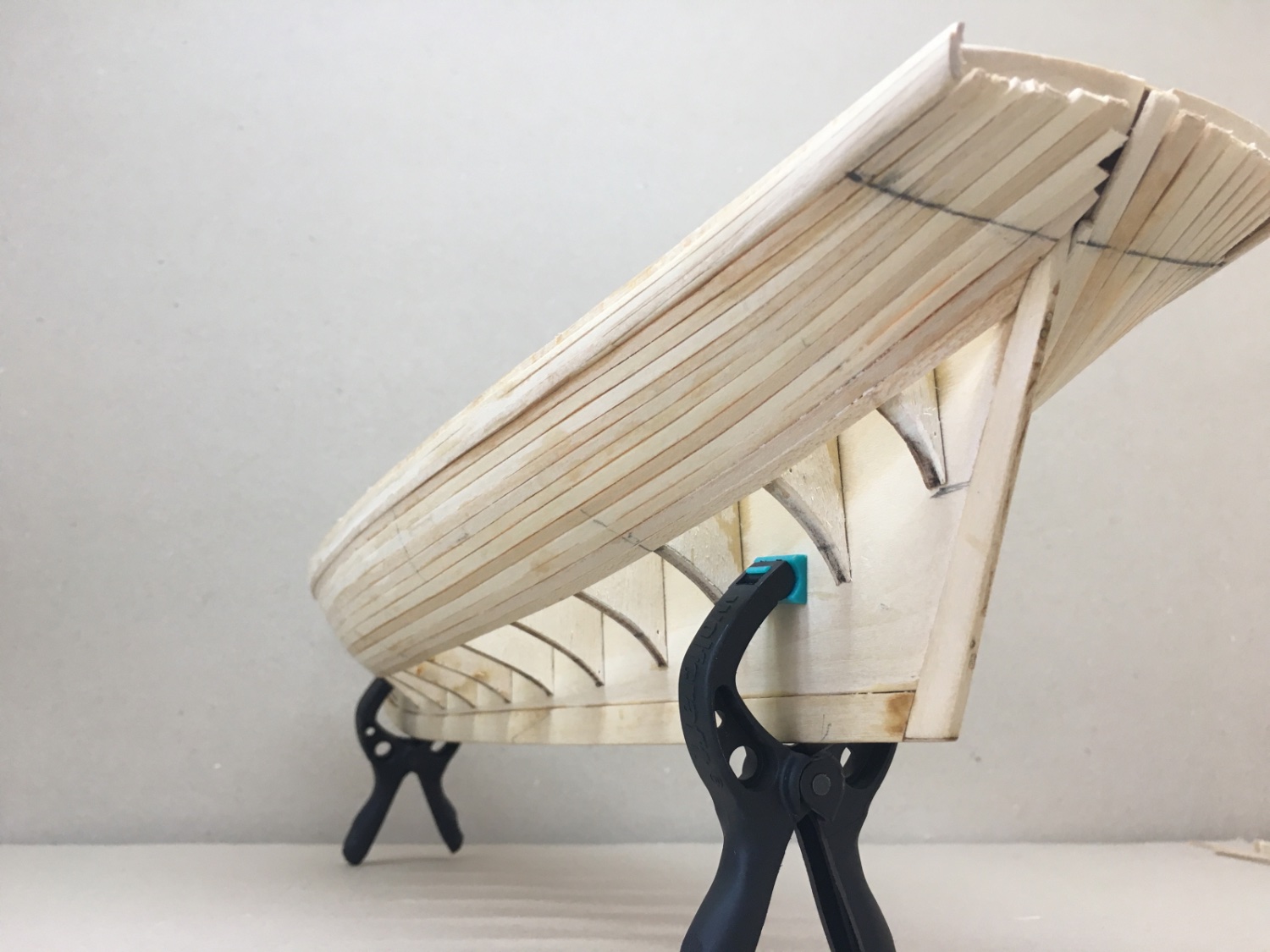
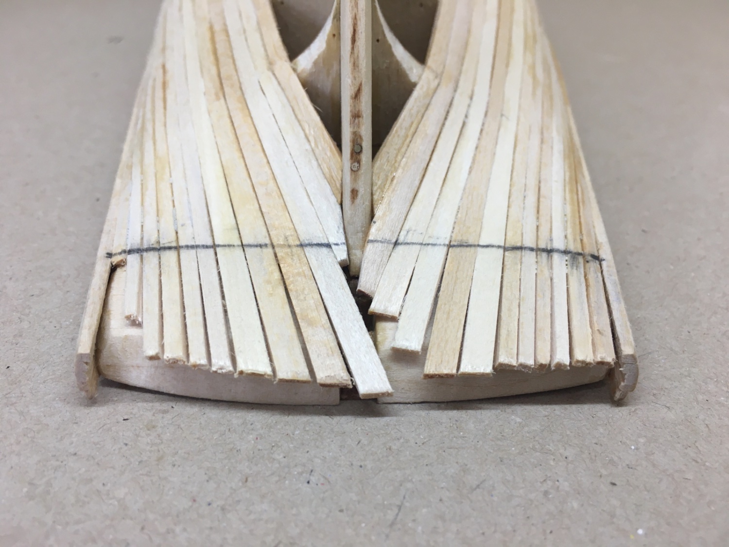
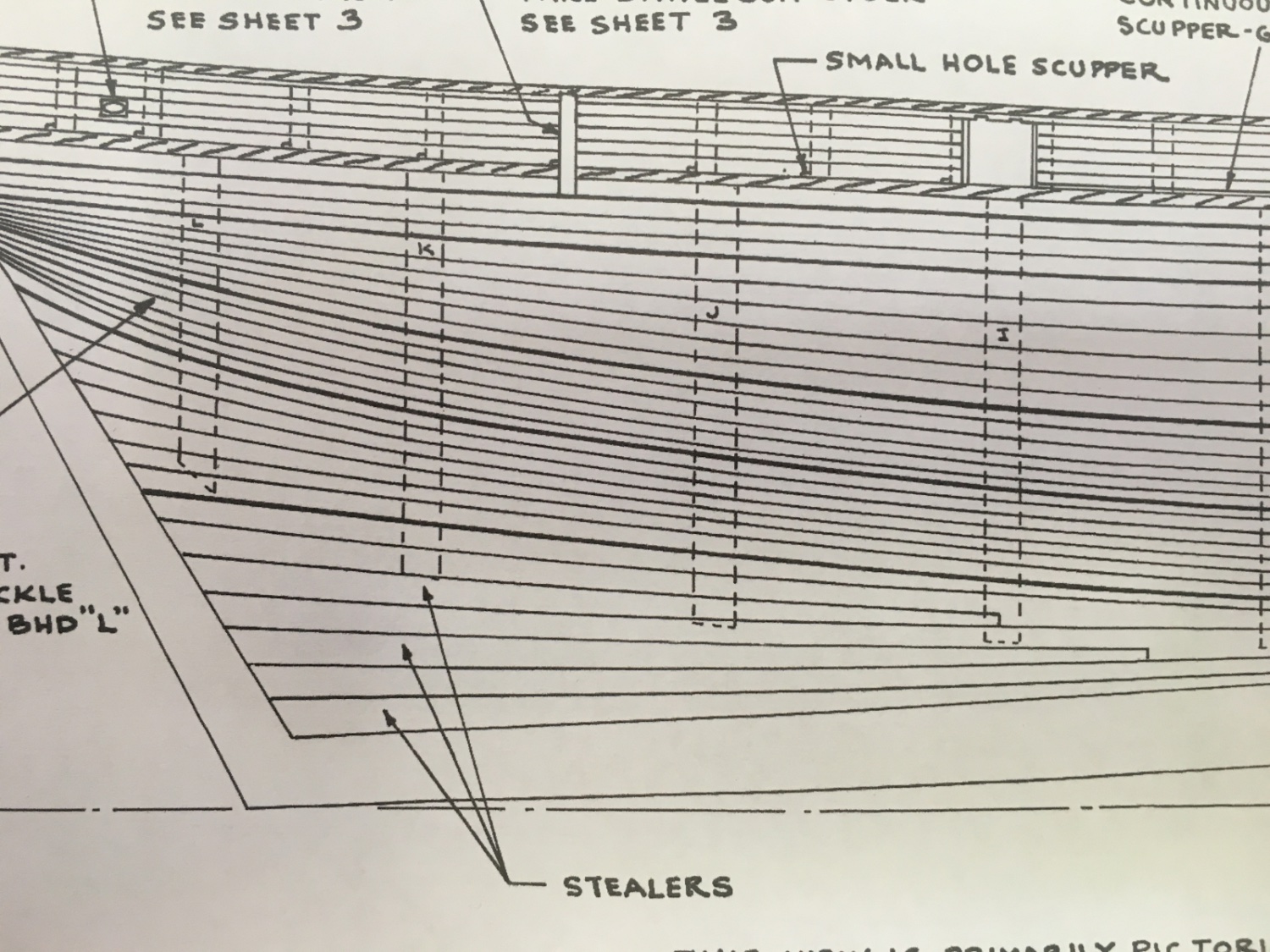
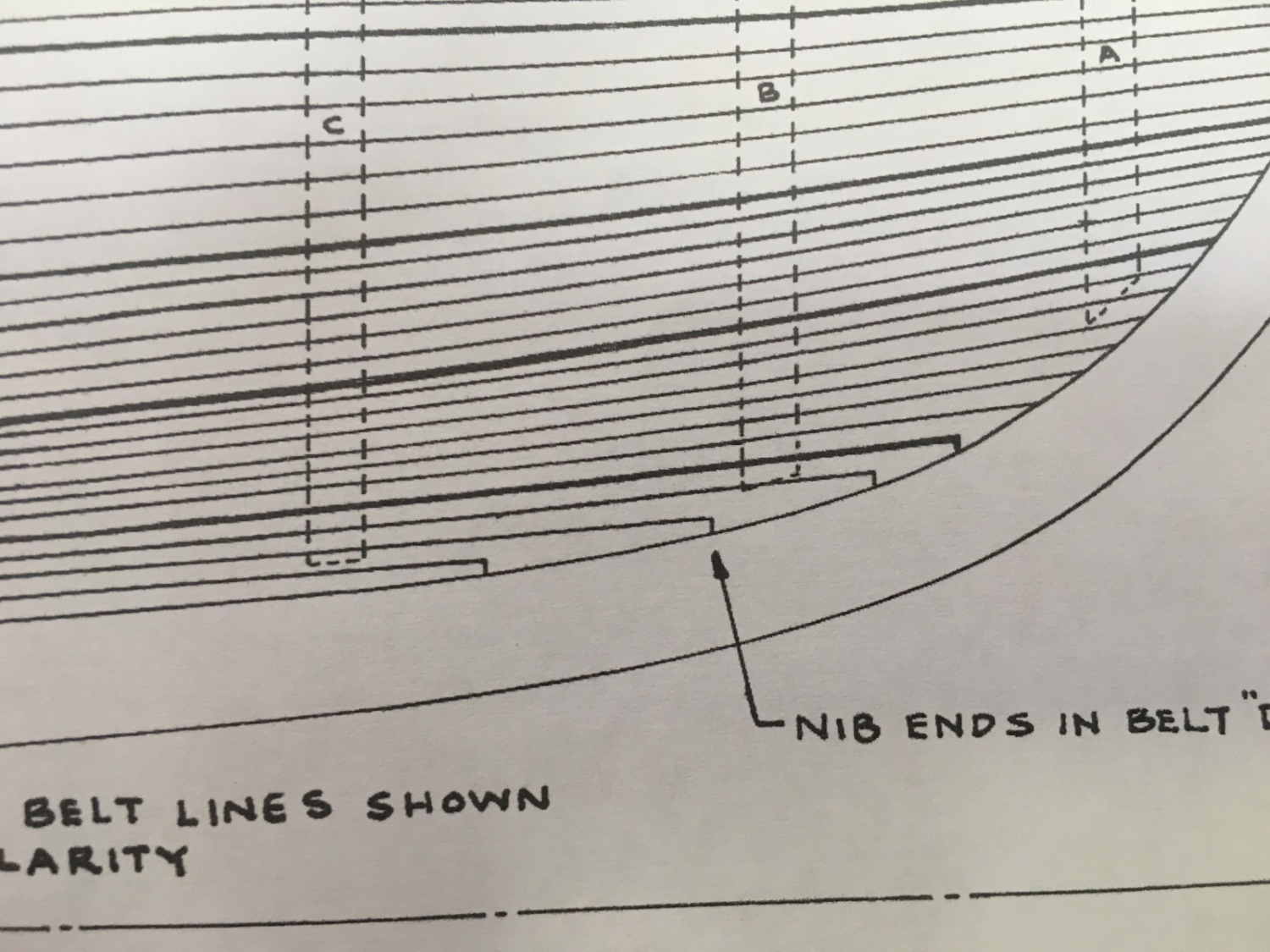
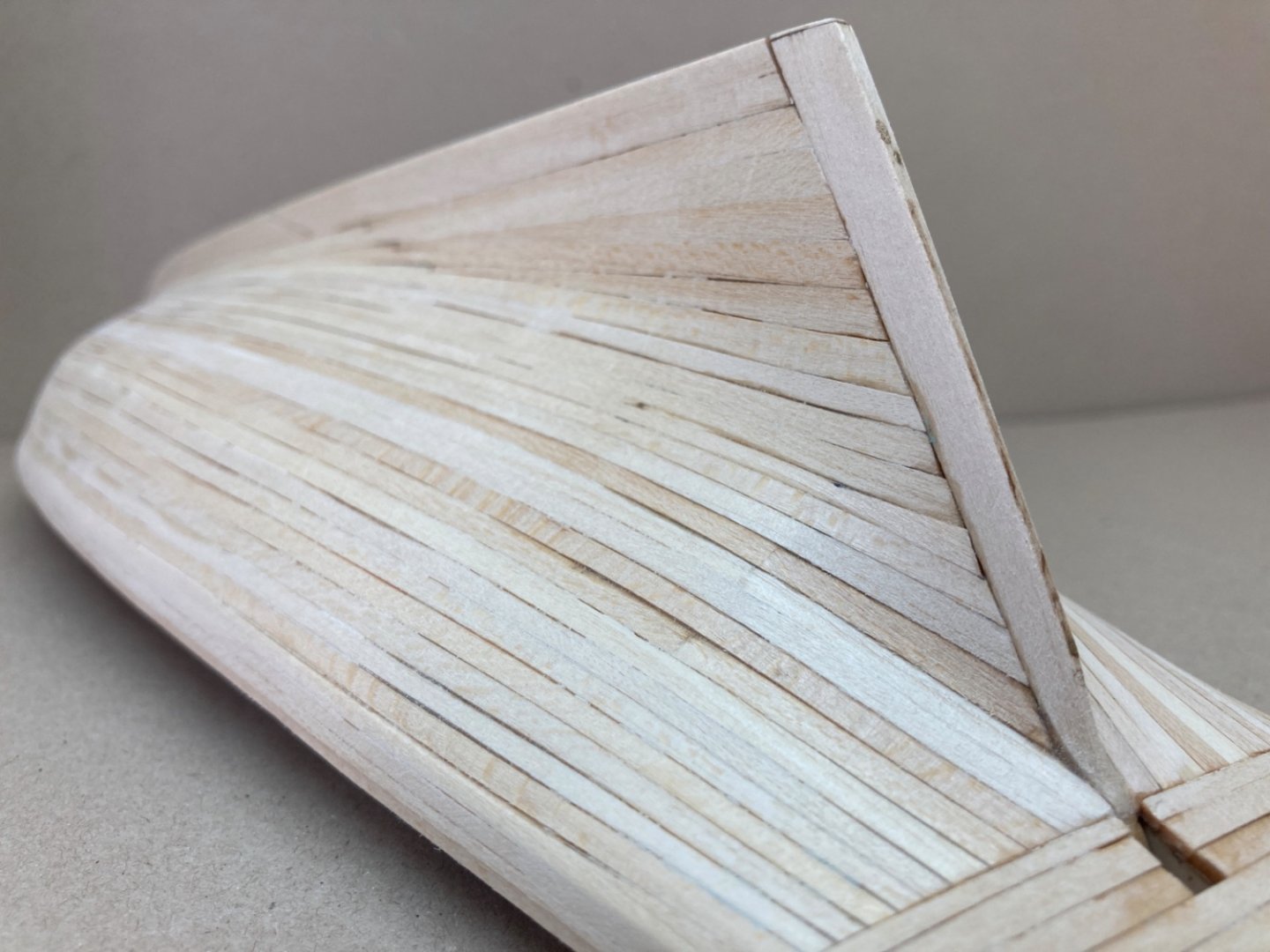
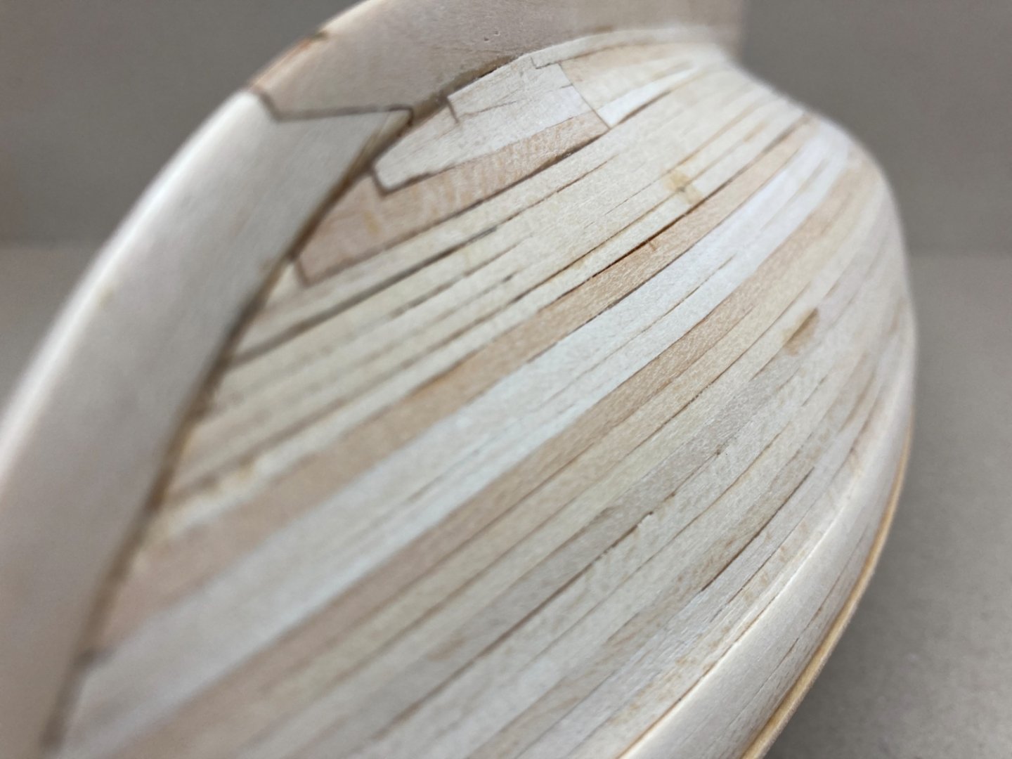
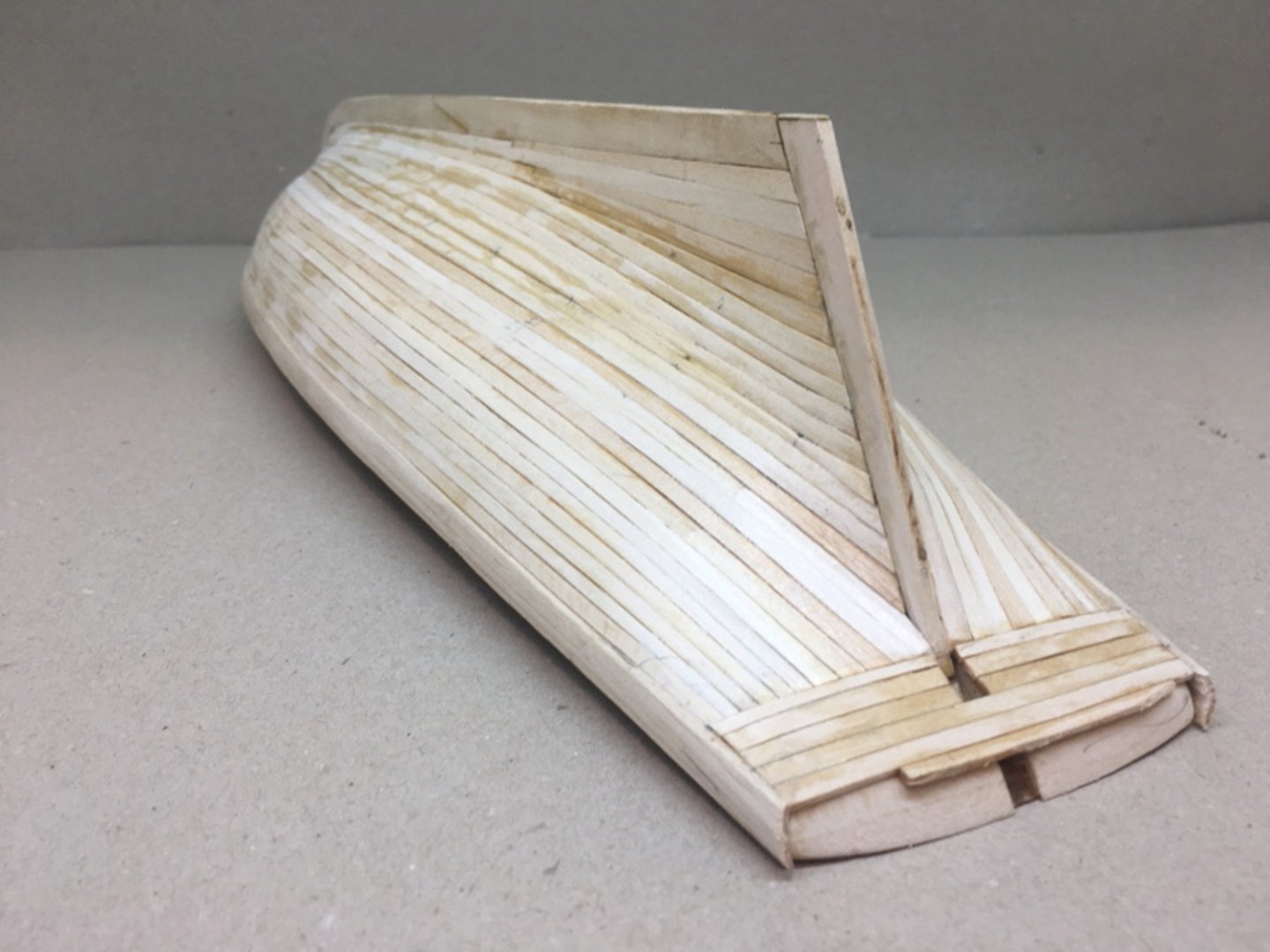
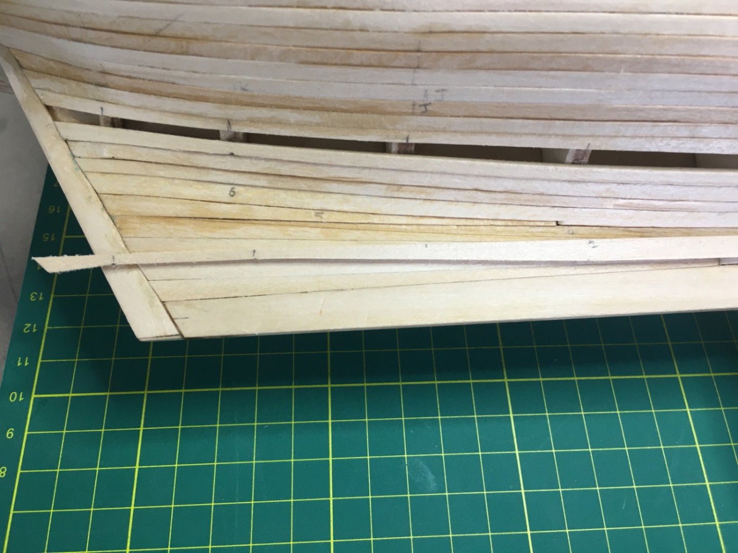
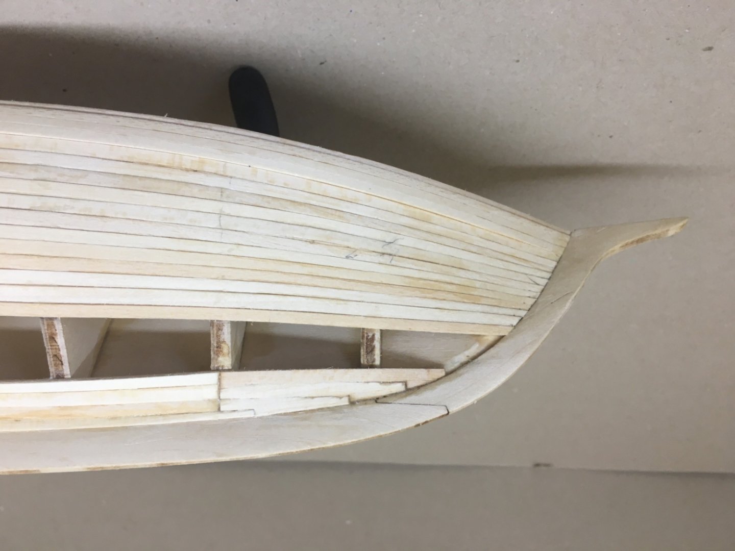
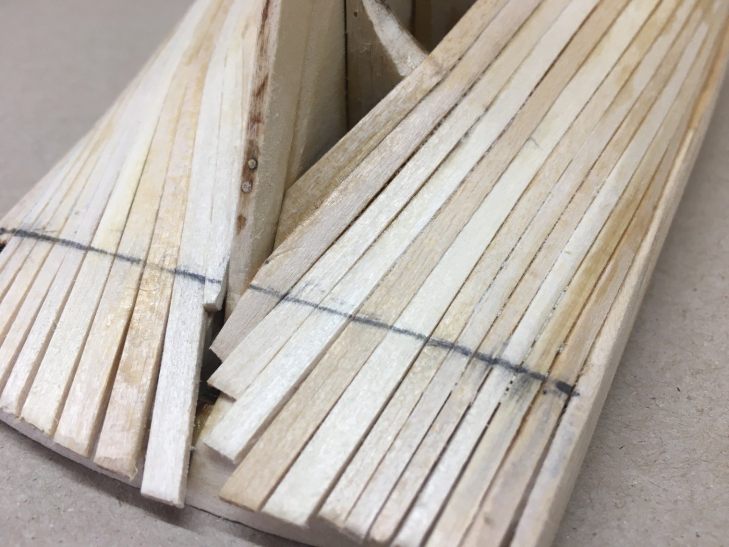
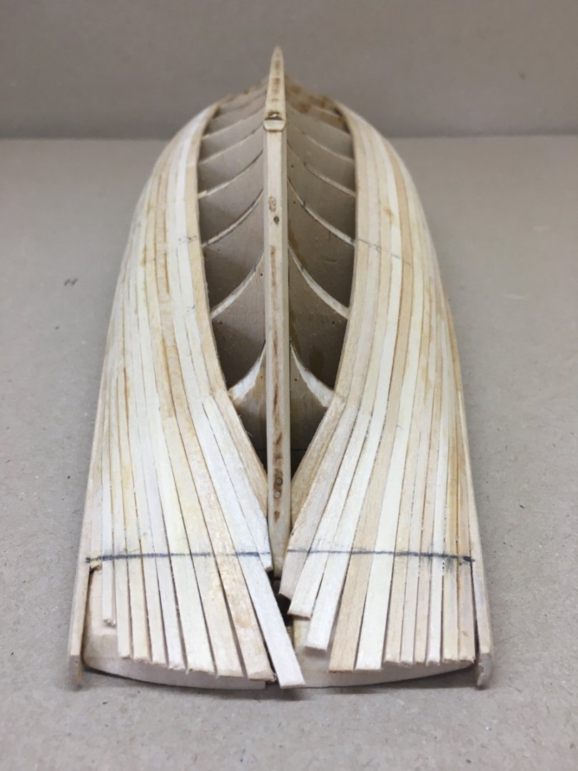
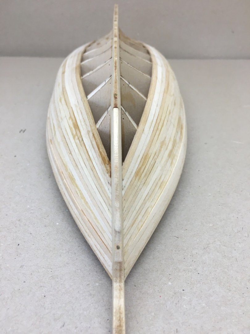
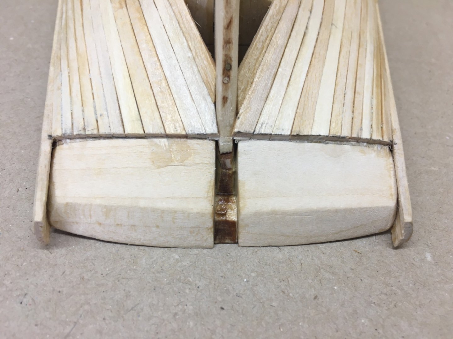
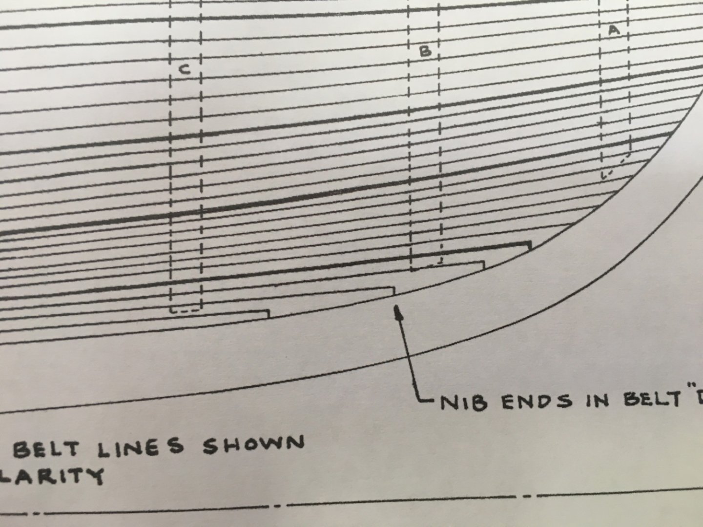
I did enjoy the zone D planking a lot with all the new (to me) terms like stealer planks and nib ending planks. By referring to the initial zone markings and taking them as zone borders and keeping in mind that the plans are not 1:1 in this zone, I improvised a lot and finished with 4 rows of planks at the mid bulkheads. However I did not like the initial finish at fore on both sides and redid the rows 2-4 from bulkhead C to forward on starboard side and row 4 on port side also from bulkhead C to forward. Here are pictures from starboard side (Please note that some pictures are inverted upside down and seem to be hanging from above. I aimed a more accustomed look to the model as were are used to see bottom at bottom and top at top ) Port side Various other angles


- 114 replies
-
- 2
-
-
- Pride of Baltimore II
- Model Shipways
- (and 1 more)
-
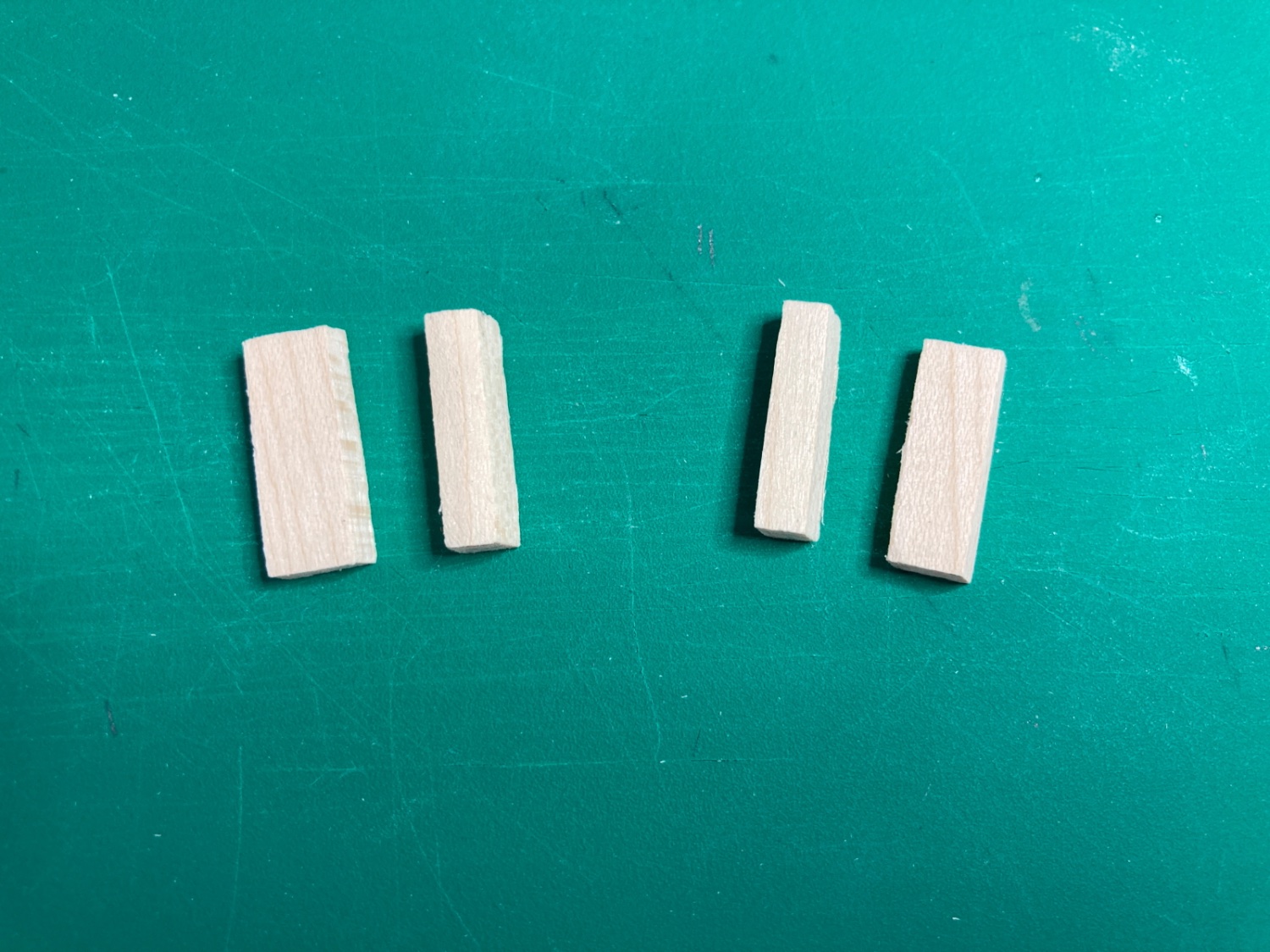
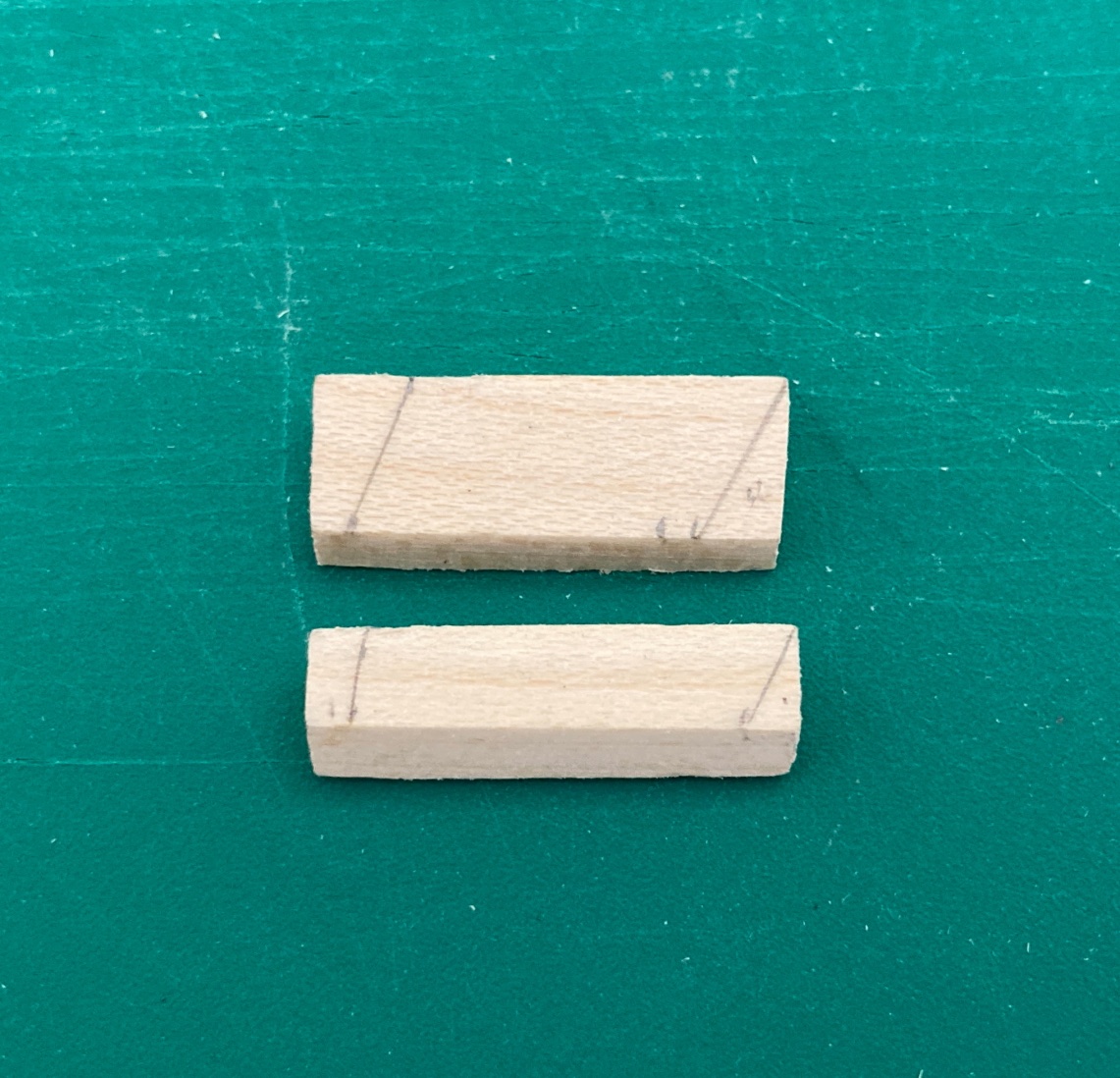
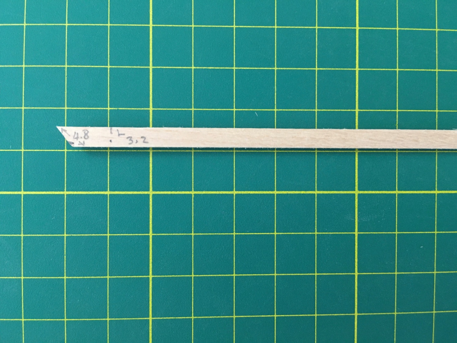
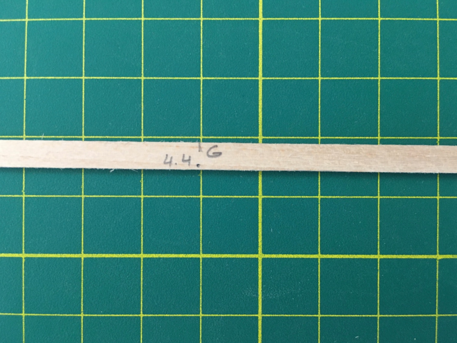
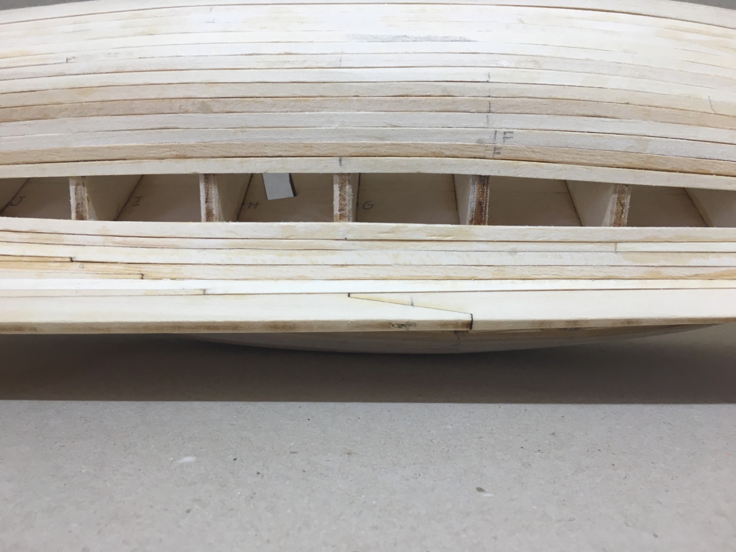
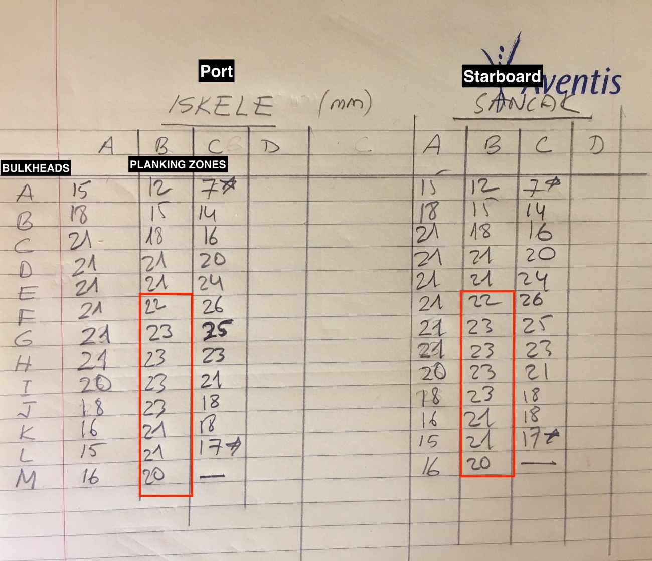
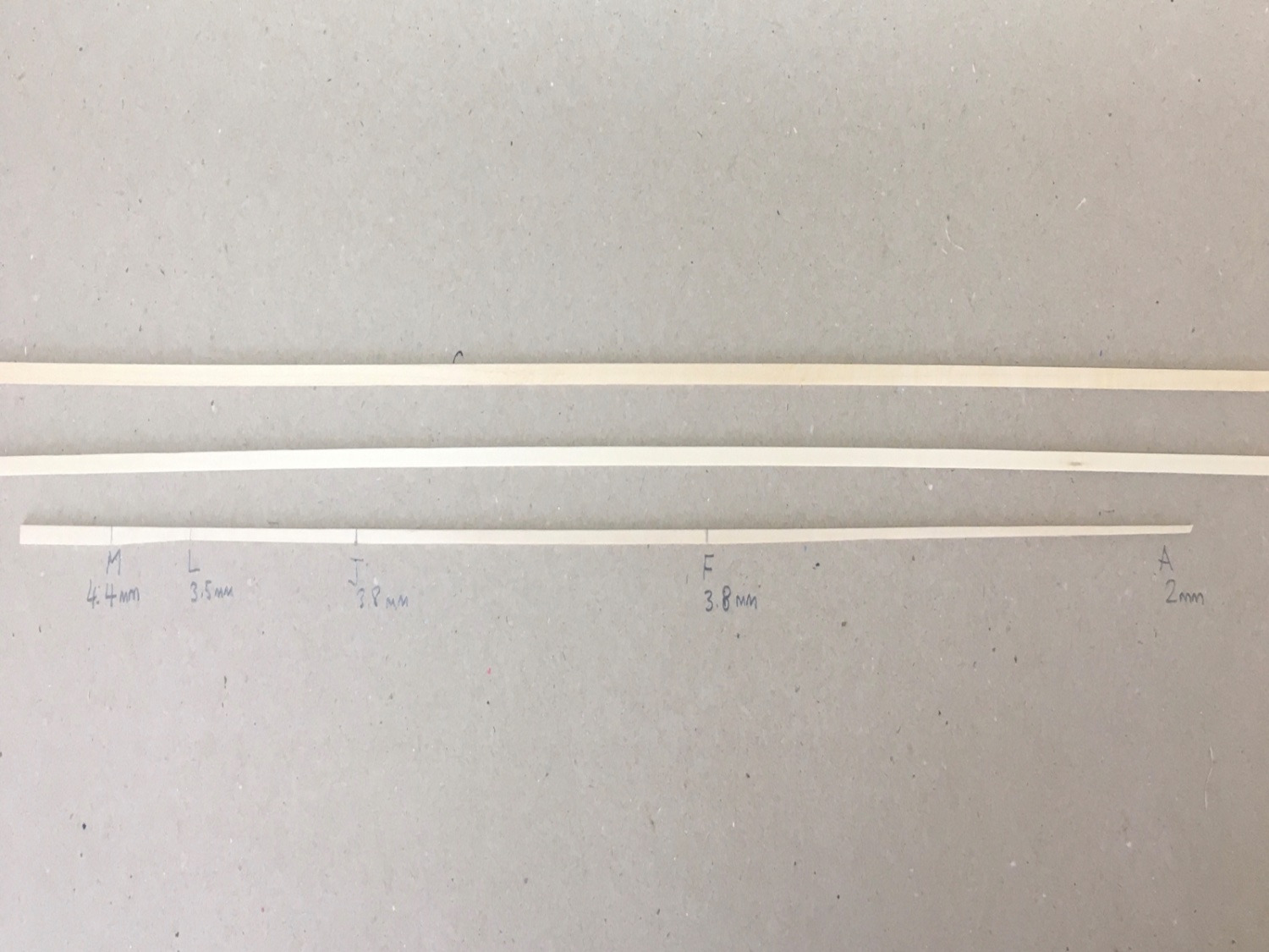
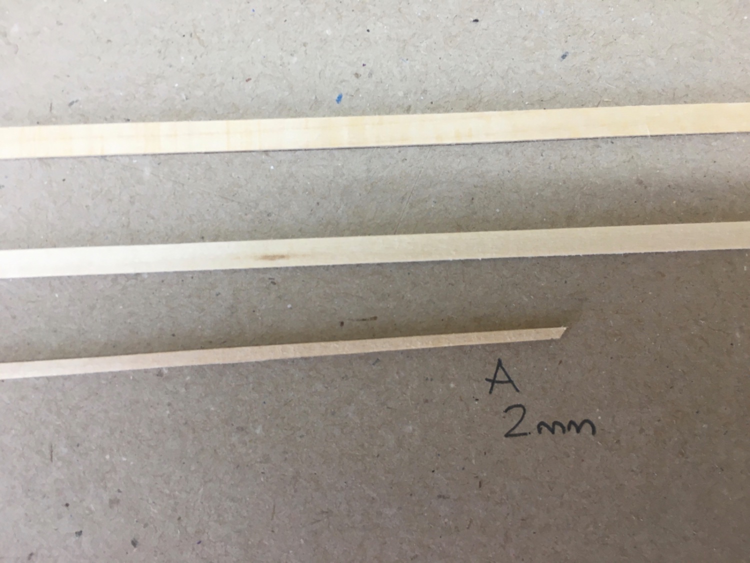
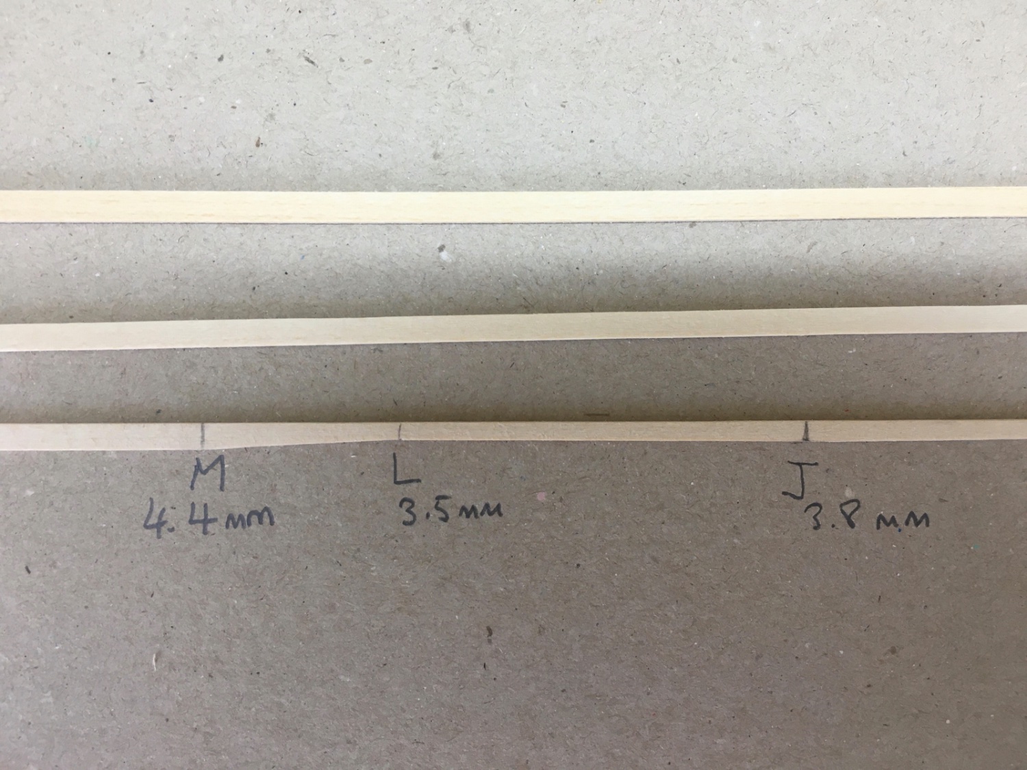
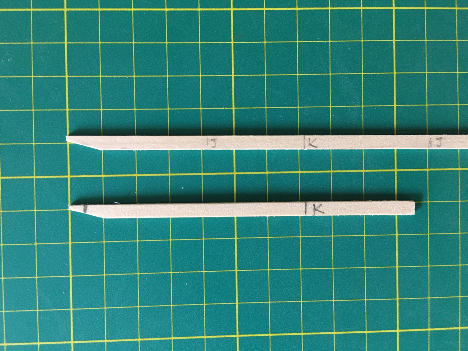
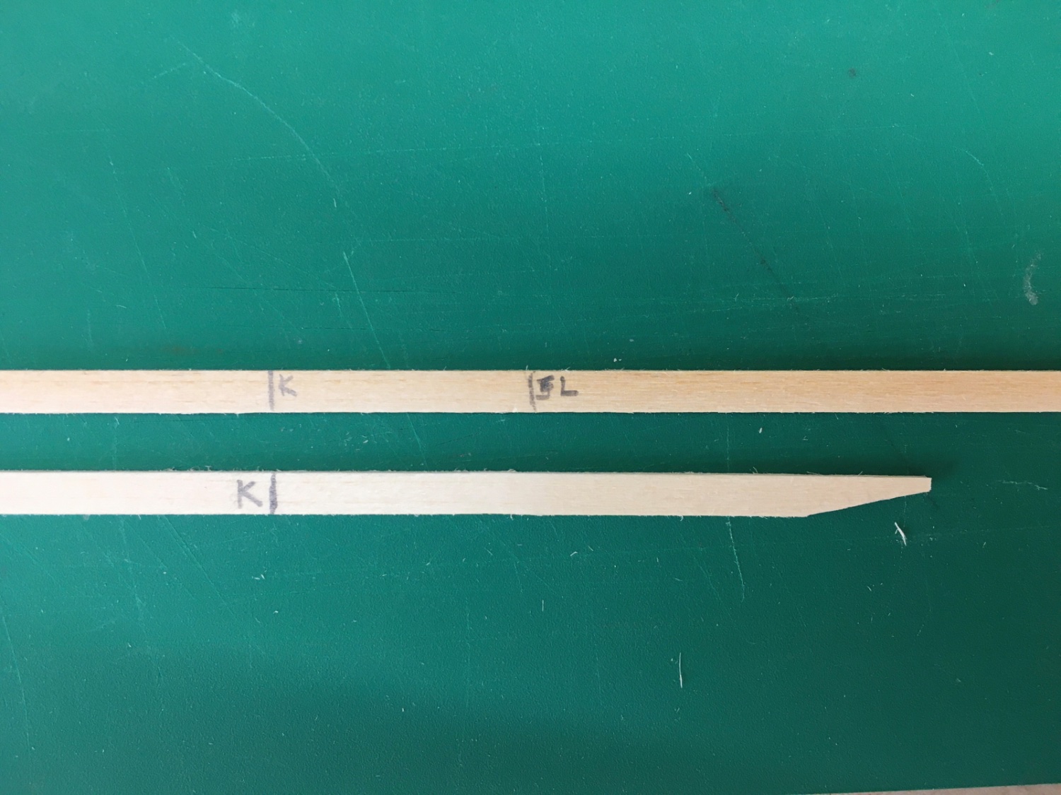
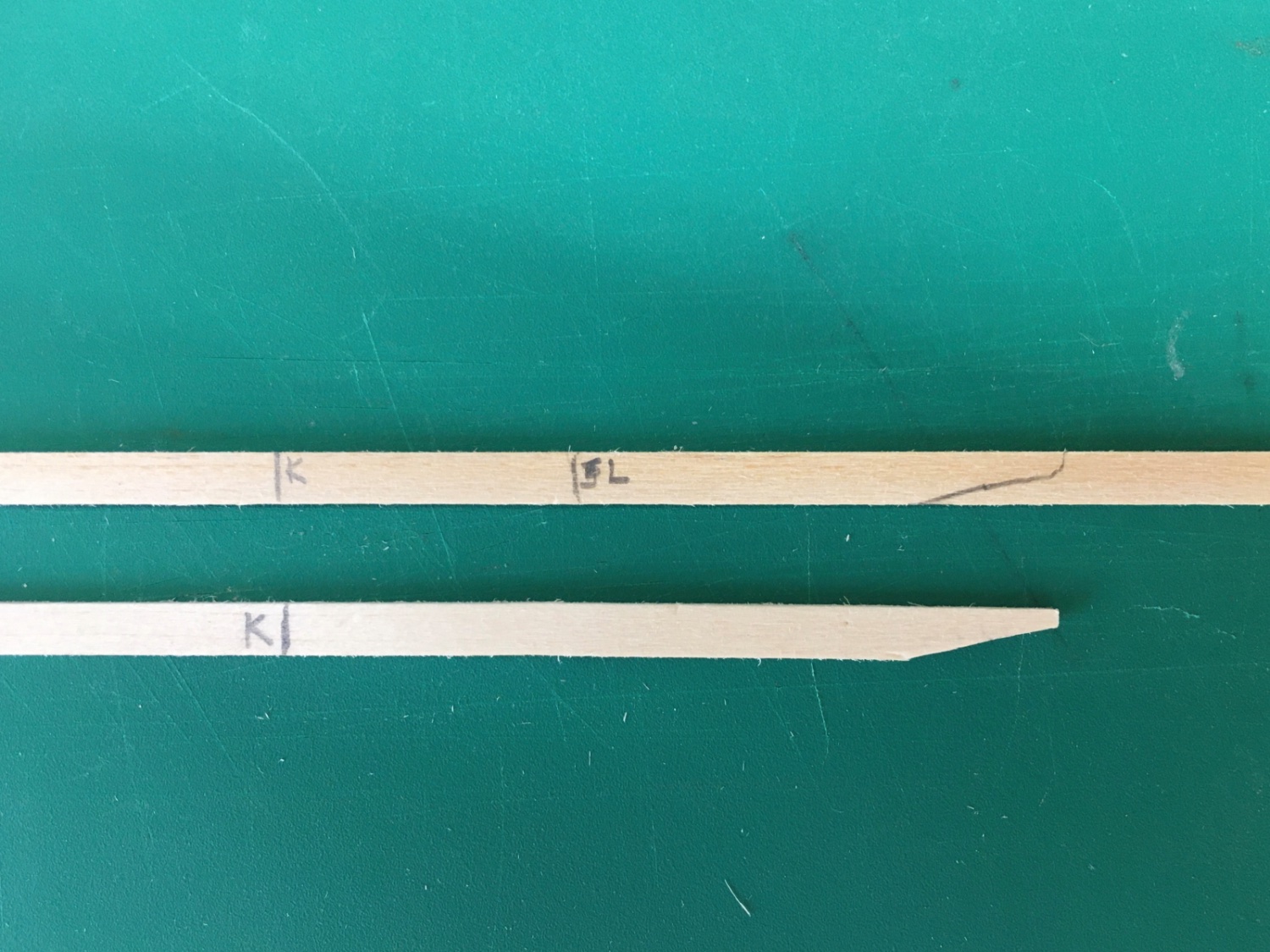
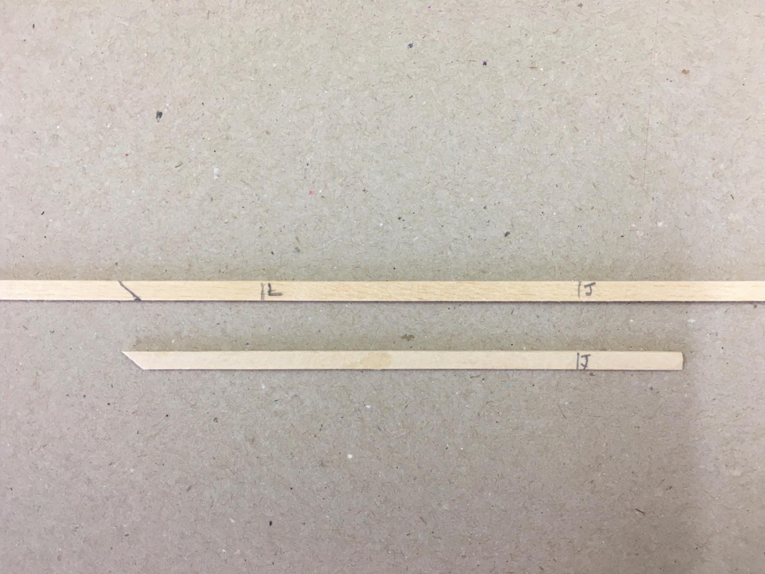
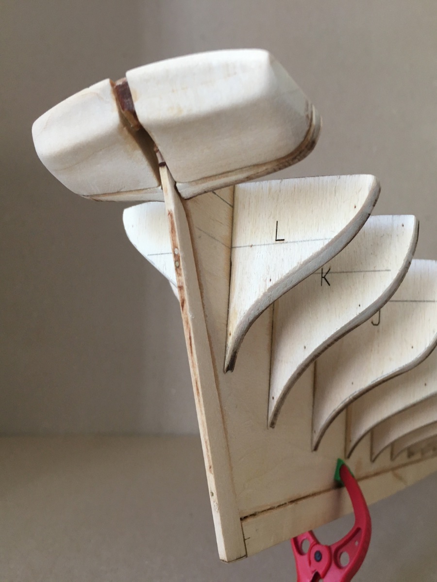
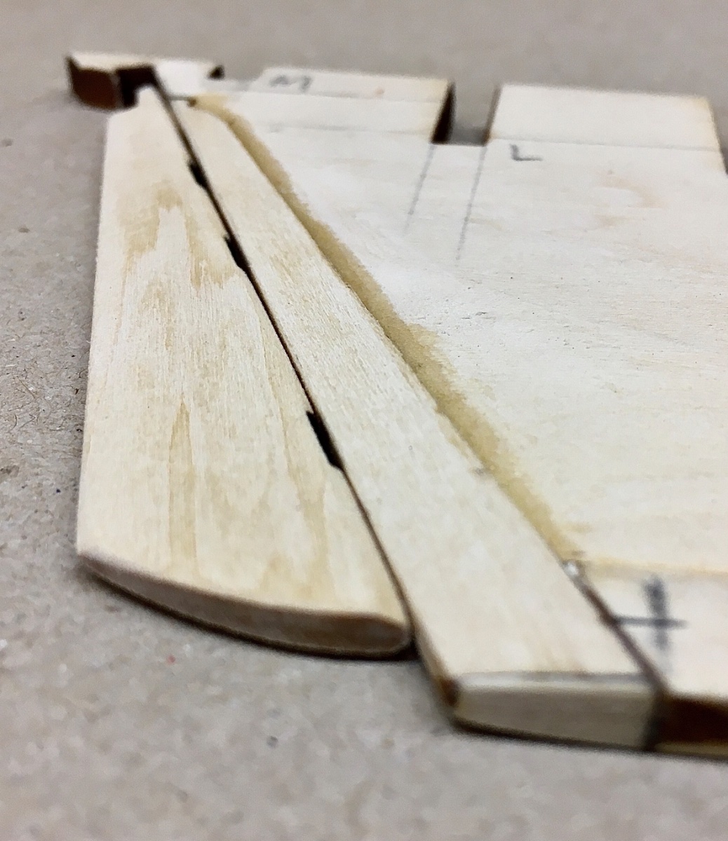
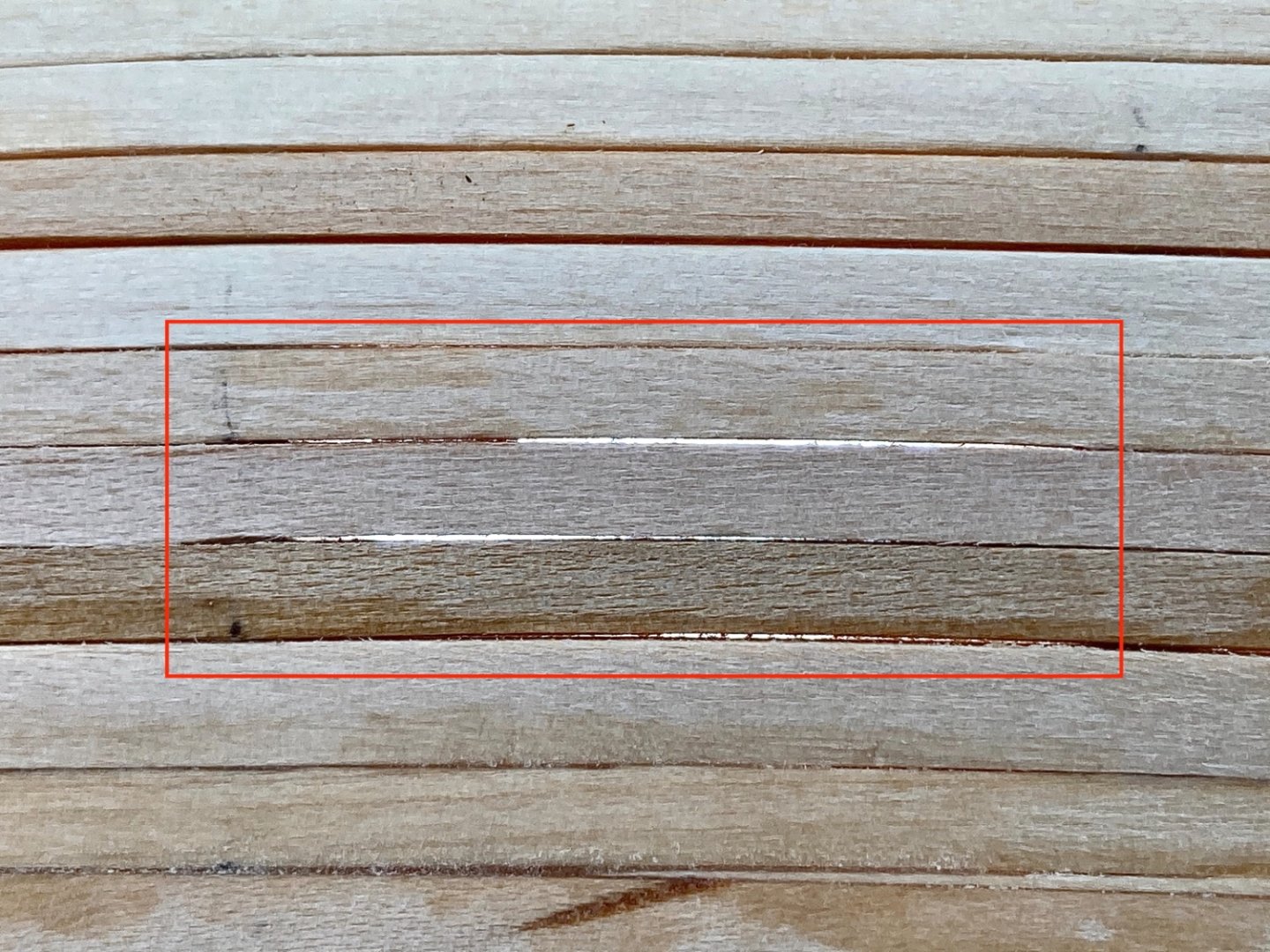
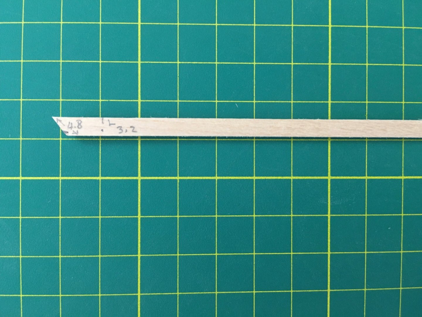
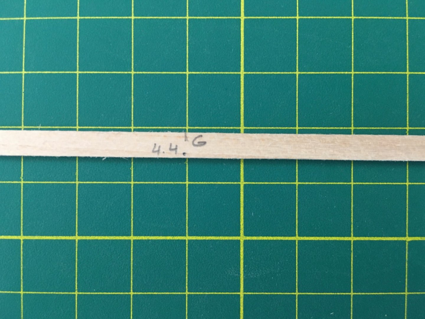
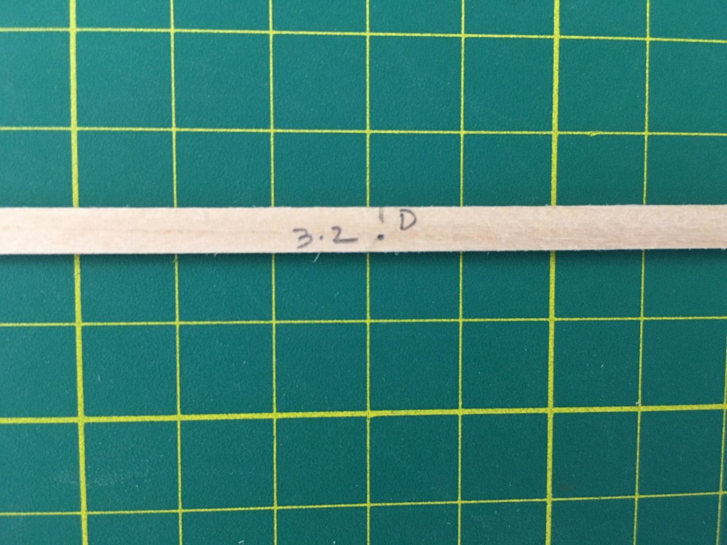
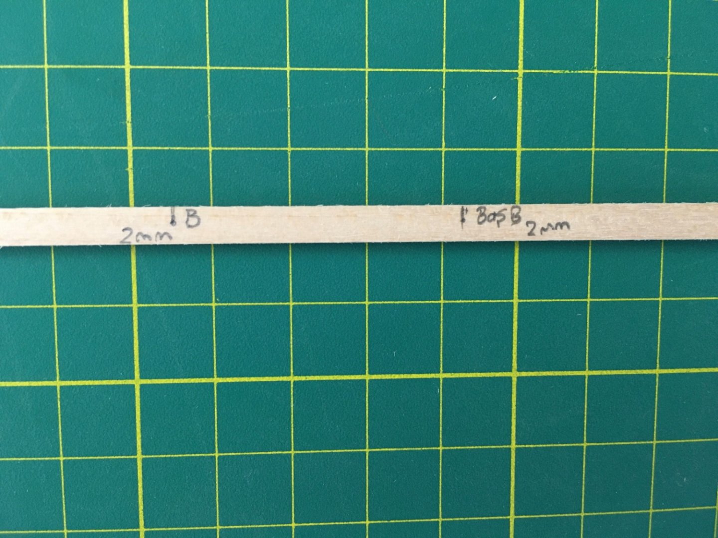
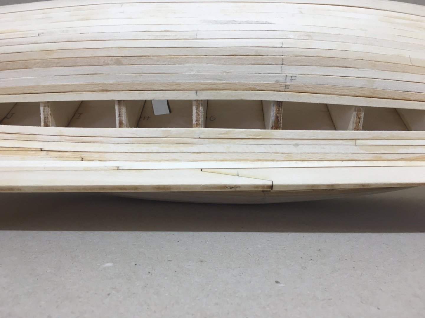
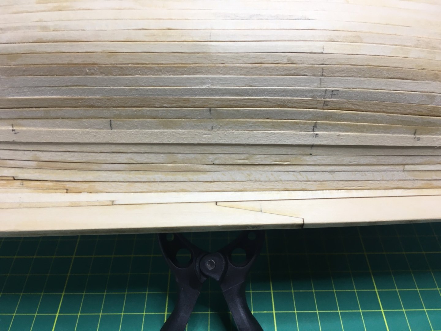
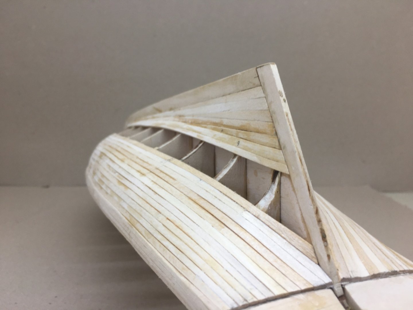
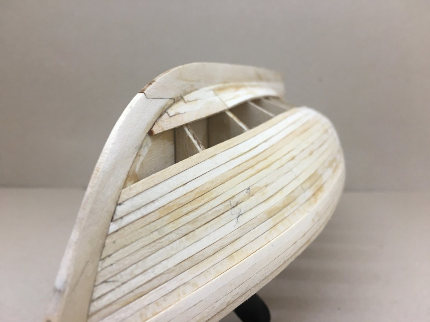
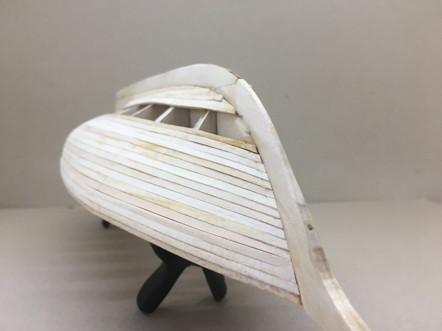
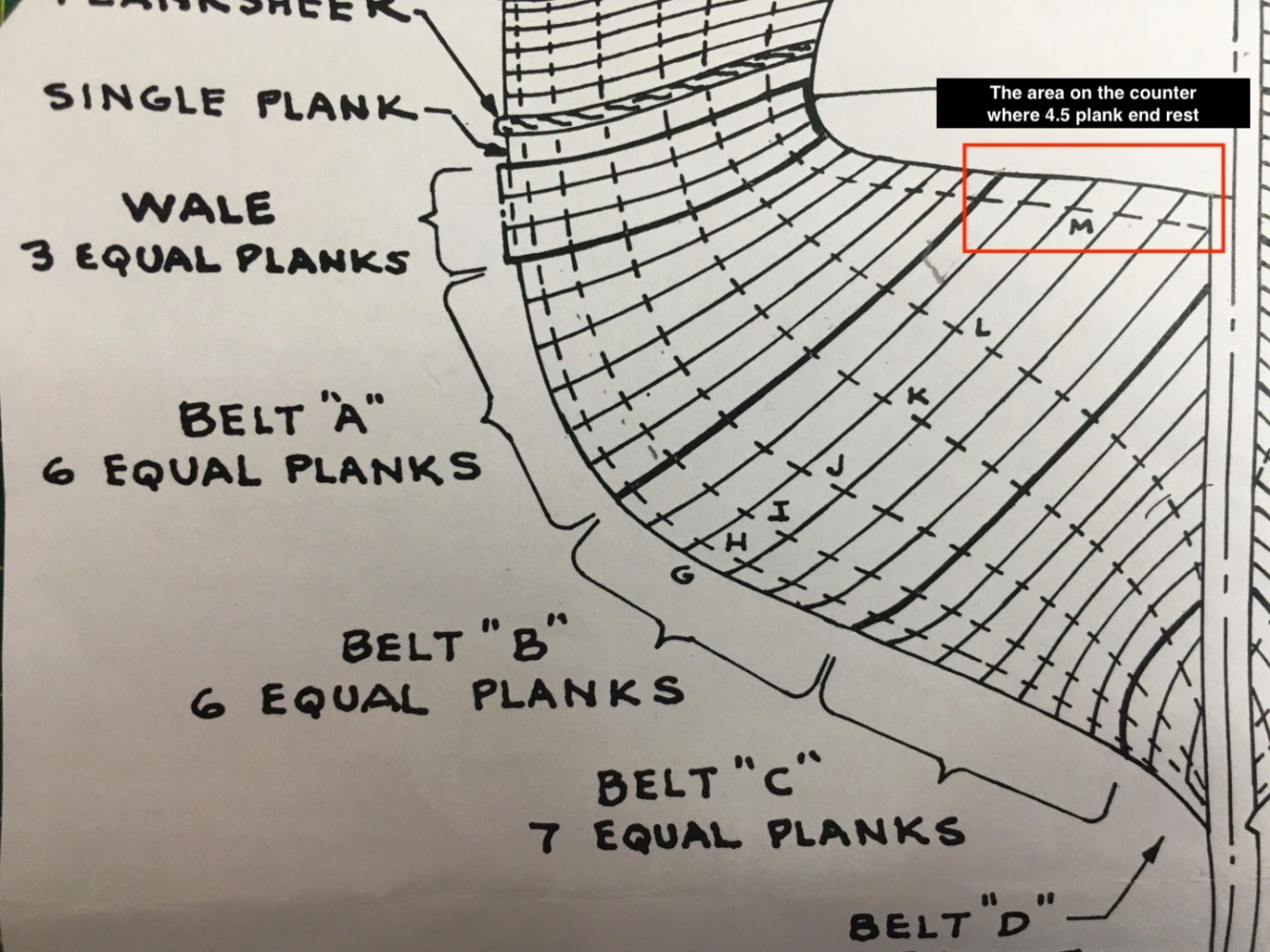
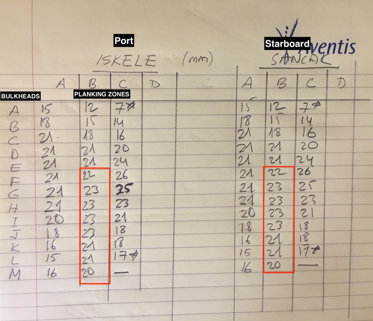
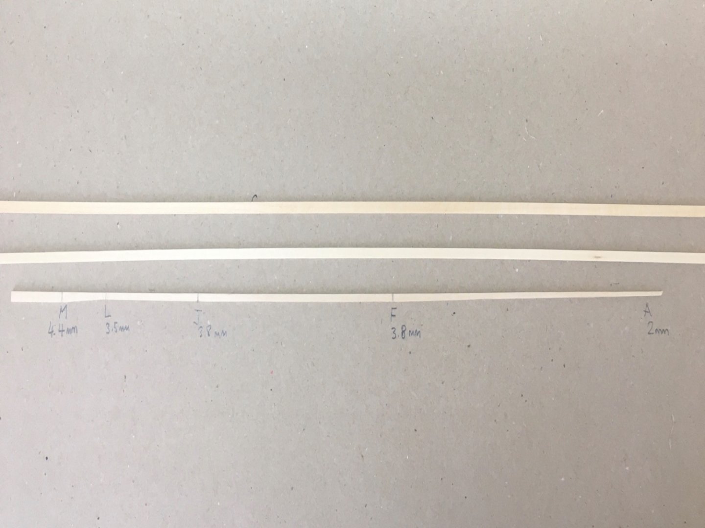
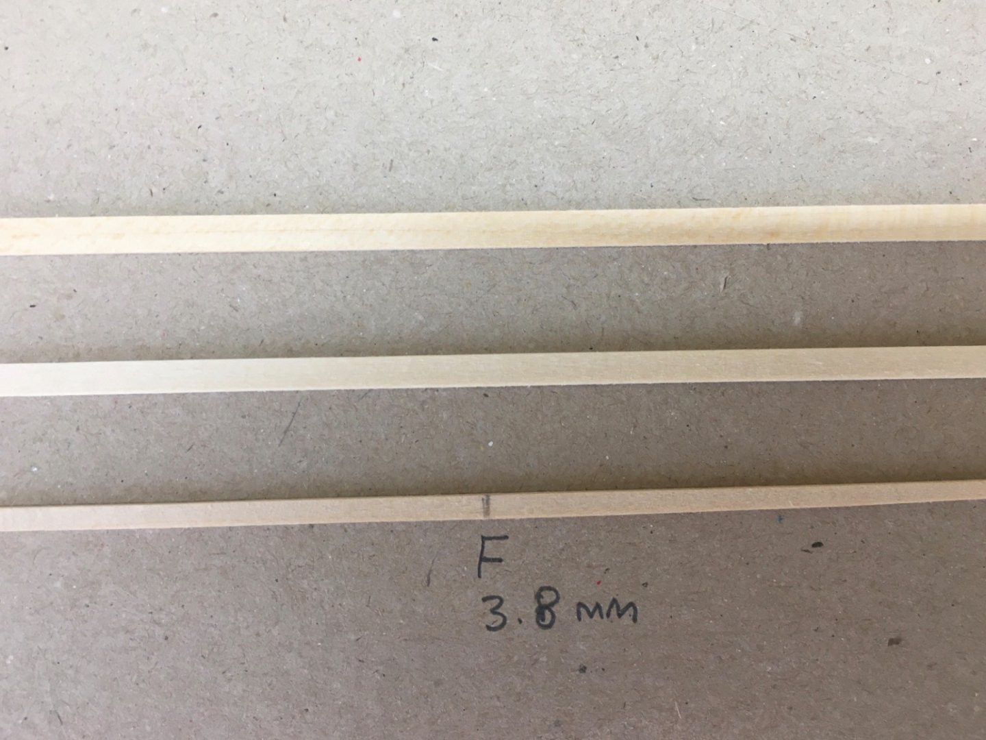
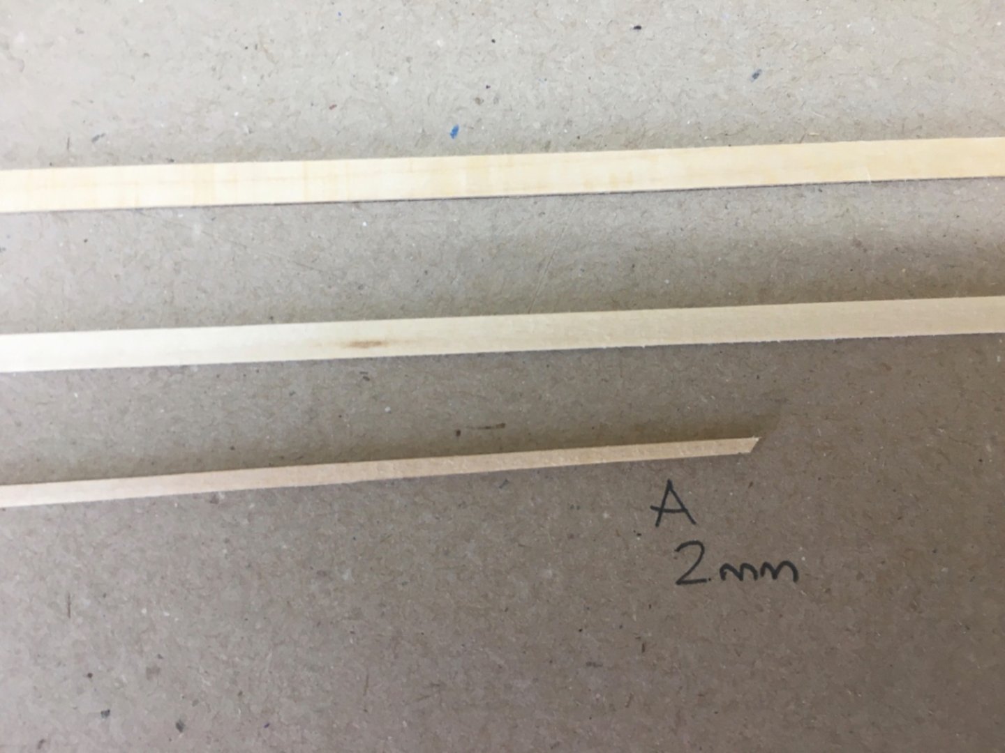
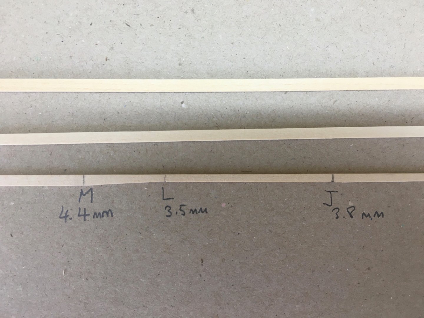
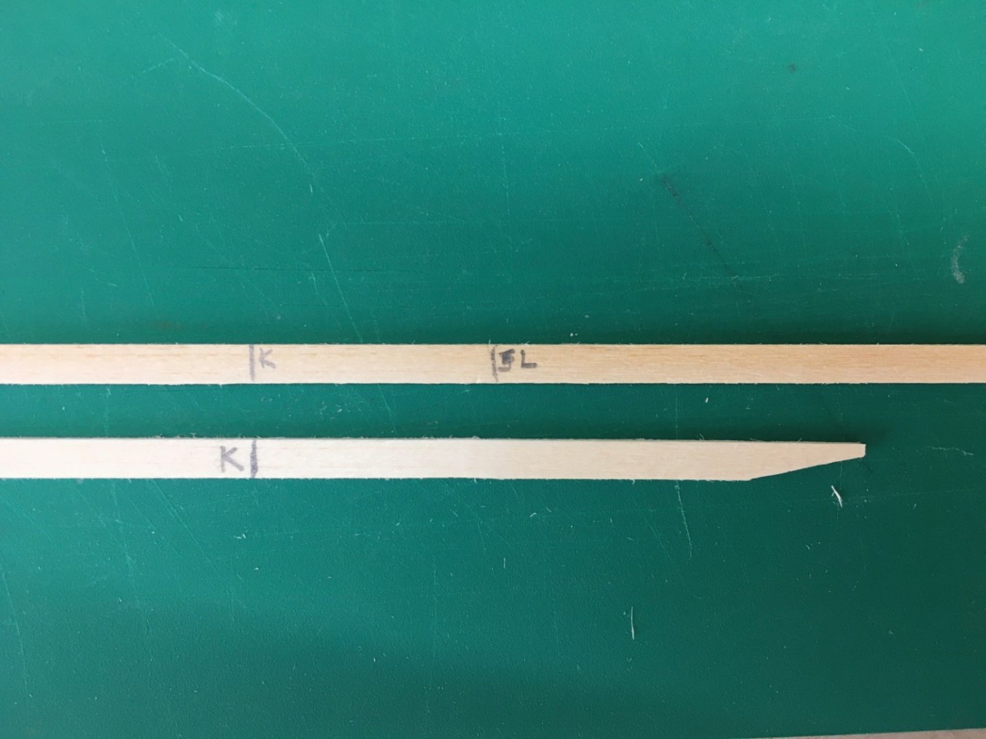
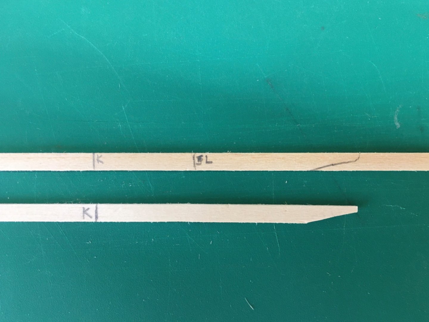
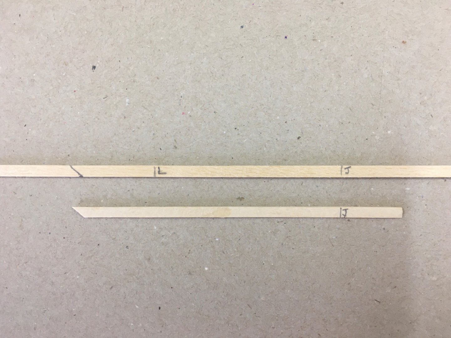
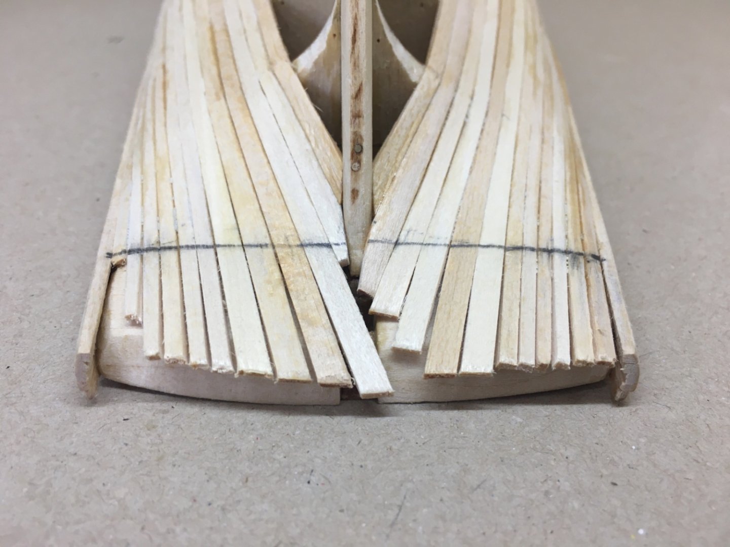
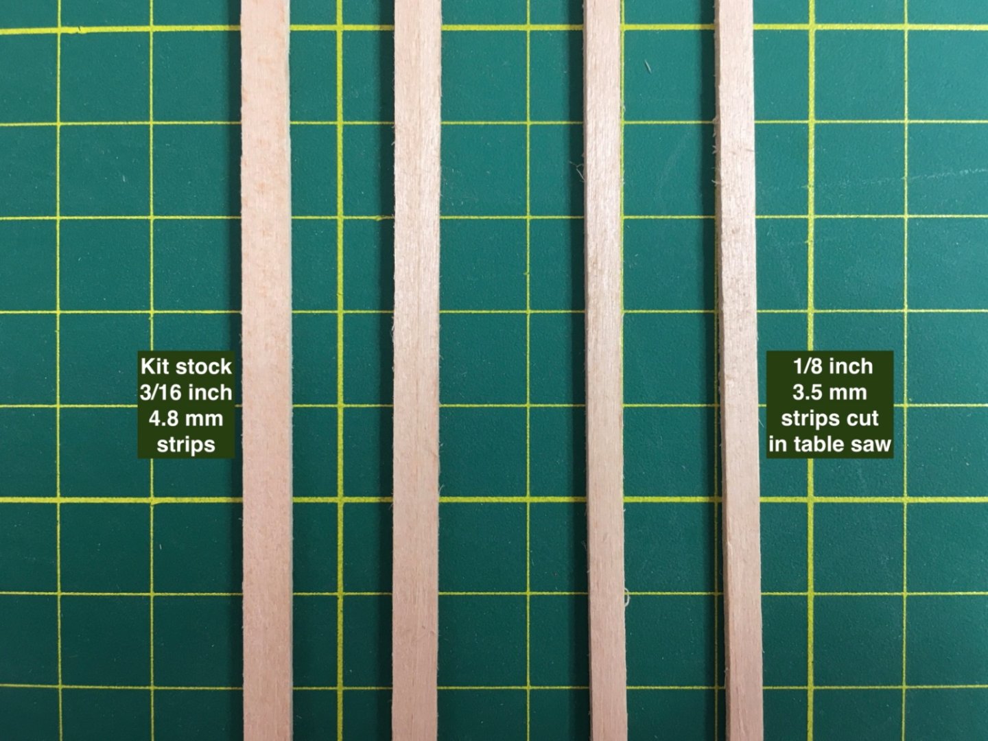
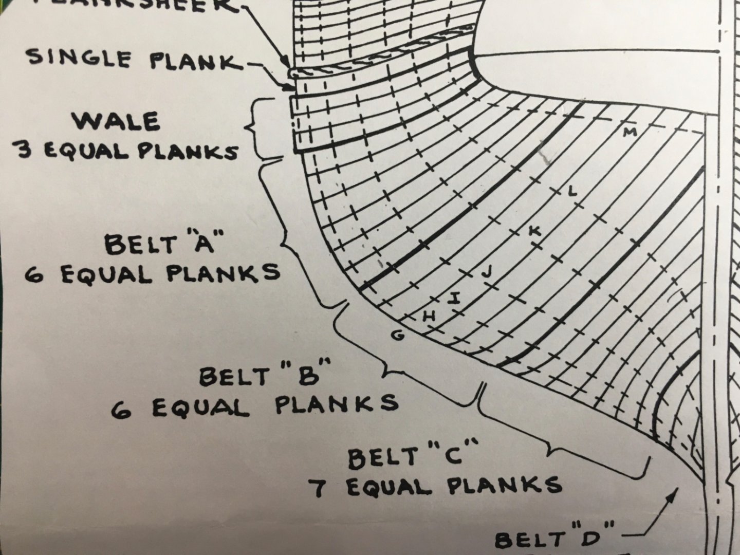
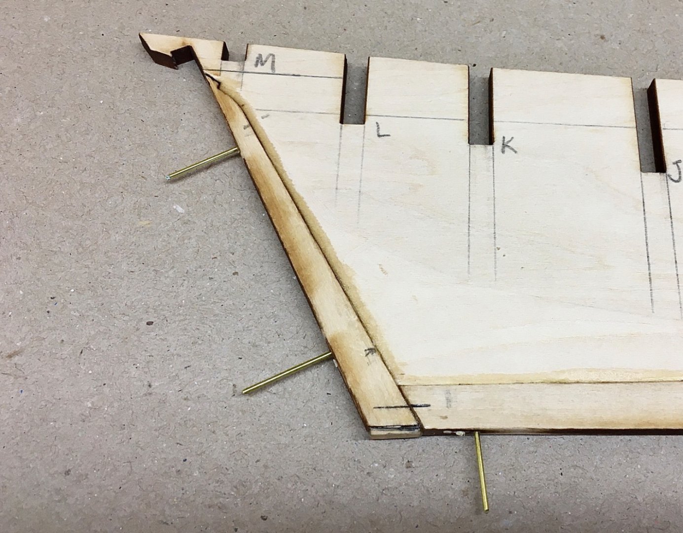
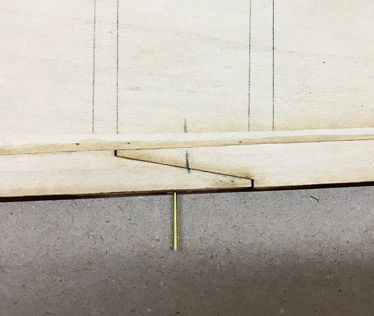
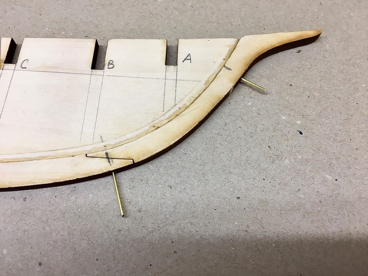
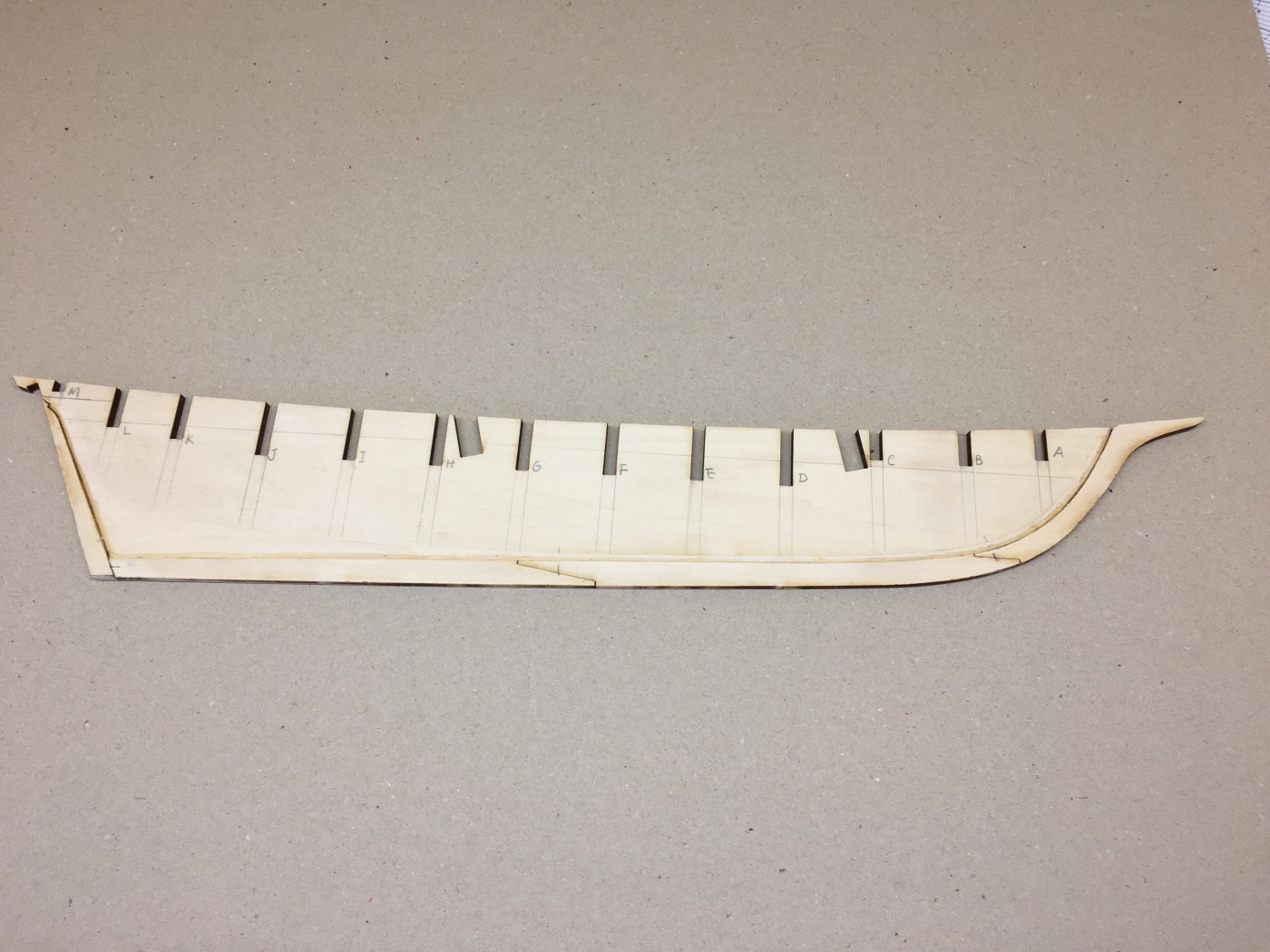
Before starting to post the Zone B plank installation, I repeat the reason why I left Zone C in the installation order. Zone A is a natural start from deck side as there are already installed 4 rows of planks there. Zone B and D have challenges and are not straight forward builds. However Zone C planks are pretty much straight forward and lay between stem at fore and sternpost at aft. Leaving it for the final stage makes it easy to make recalculations on the planking geometry and which was indeed what happened as you will see in the coming posts. Zone B has two differences from zone A. Although it has 6 planks , same as zone A, the width of the zone is larger than zone A in several bulkhead locations. Also unlike zone A , not all the planks but 4.5 of them lay on the counter after bulkhead M. Half of row 5 plank lays on counter and half of it on sternpost. Plank row 6 ends on sternpost. Because of these differences , new calculations were to be made. As the width of Zone B at bulkhead M is 20 mm and there will be 4.5 planks to be placed on the counter after passing bulkhead M the width of the planks at that location must be 4.4 mm ( 20/4.5). Other bulkhead calculations at critical locations are 2 mm at Bulkhead A, 3.8 mm at Bulkhead G, 3.8 at Bulkhead J and 3.8 at Bulkhead L. These calculations mean that I had to use the kit's original stock strips and do the tapering job on them again by marking the above measurement results. Here are the two pictures to remind the reason for the calculations above. The first 4 rows in zone B were straight forward after the preparation and tapering of the planks. First 12 4.8 mm (3/16 inch) planks are cut to 4.5 mm on the table saw. After critical measurements are marked on them they are tapered again with steel ruler and new #11 blades. Below pictures speak for themselves I hope , top strip is 4.8 mm, bottom is tapered and the middle one is 4.5 mm one. Of course all the above tapering measurements are not pin point correct and depend on your experience with wood handling. Here are some pictures . After installing the first 4 rows there is a new problem . How to install the aft ends of planks row 5 and 6 ? Here I found a simple solution. After the tapering of the planks at rows 5 and 6, I left their aft ends unmarked initially. Then I prepared 4 dummy planks about 15 mms long, starting from the middle of bulkheads K in row 5 and J in row 6, carefully checking and shaping their aft ends. Then I transferred the marks on dummy planks to the real ones and cut the tapering on them. This method proved to be OK only leaving very small (less than a mm) gaps at bow between the plank and stem, which can be easily filled later. Row 5 plank on starboard Row 5 plank on port side Row 6 on starboard side Here are the finished pictures of zone B As the planking job relating the counter is finished , the aft ends of the planks laying on it can be cut off at this stage , taking the aft end of Bulkhead M as a border.


- 114 replies
-
- 2
-
-
- Pride of Baltimore II
- Model Shipways
- (and 1 more)
-
OK Thank you….
-
Hello I wonder is there a shortcut to open a specific post number in a blog ?
-
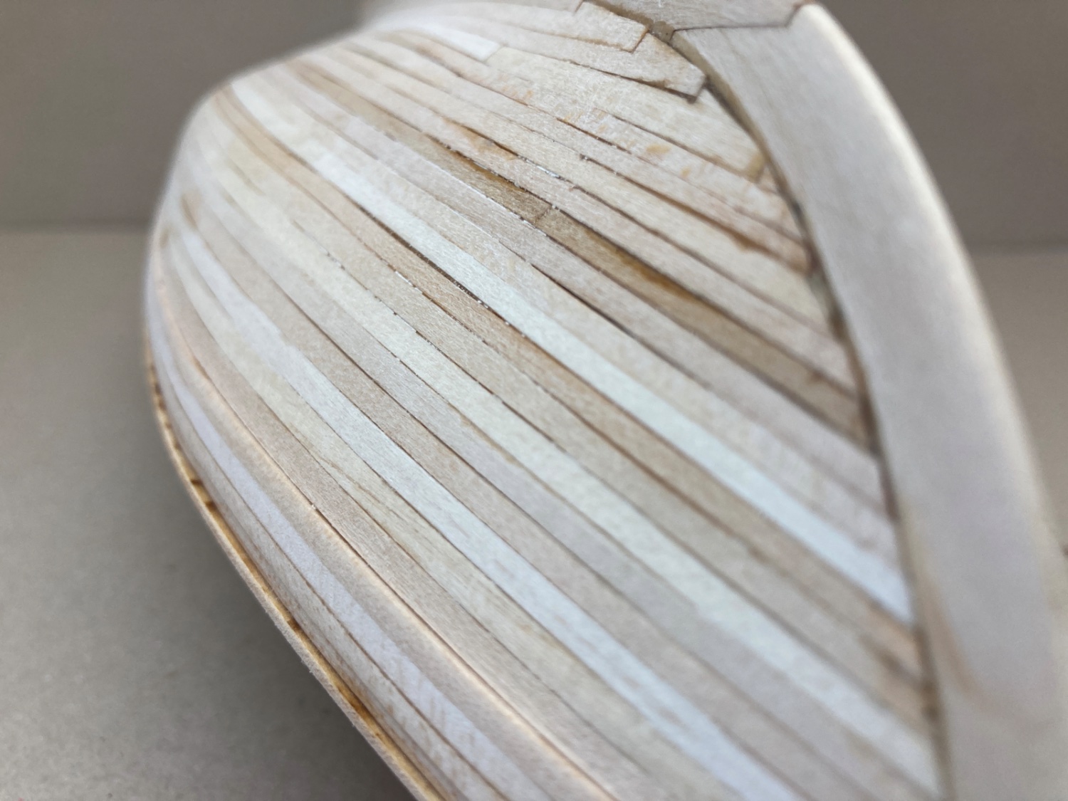
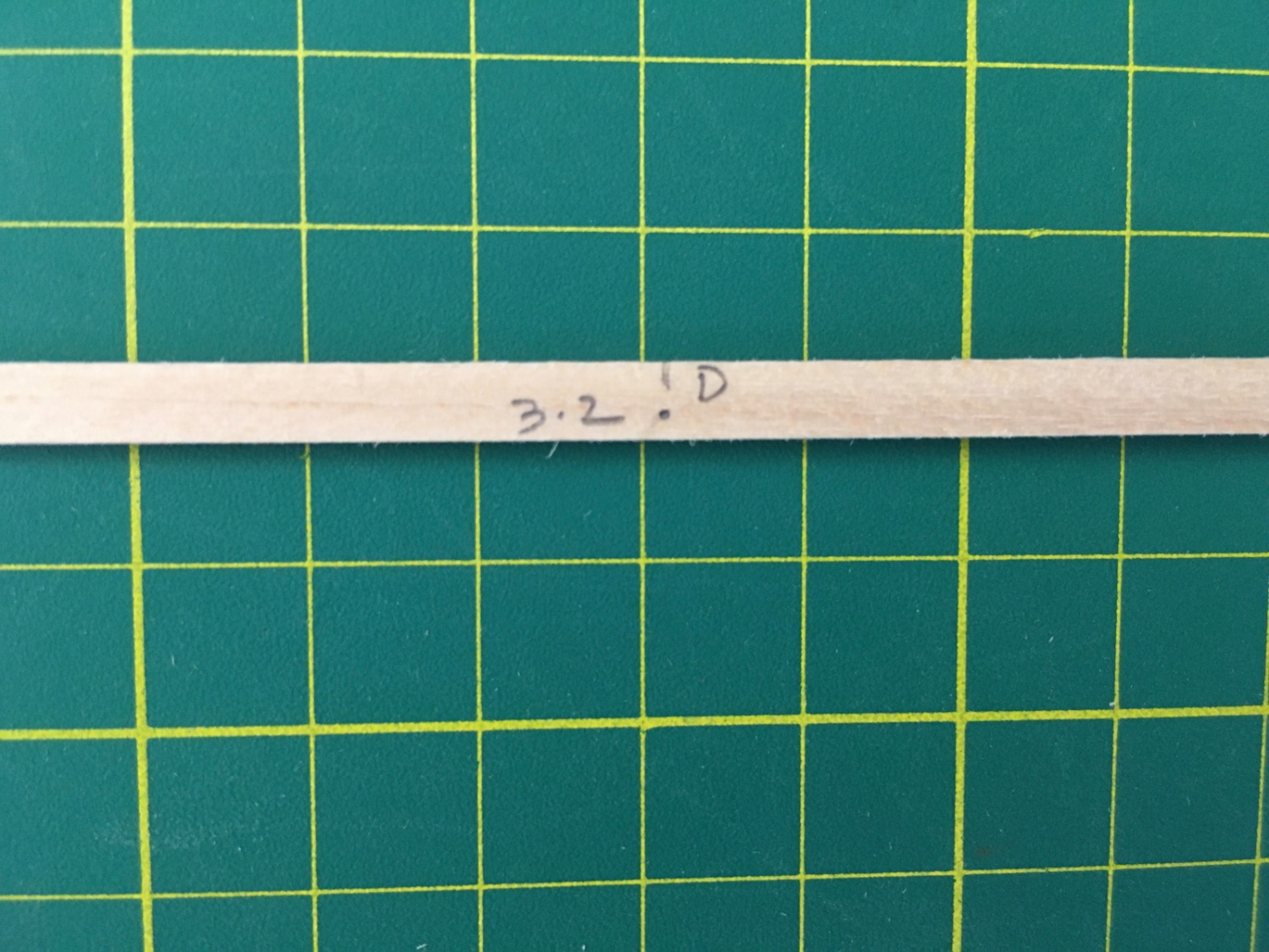
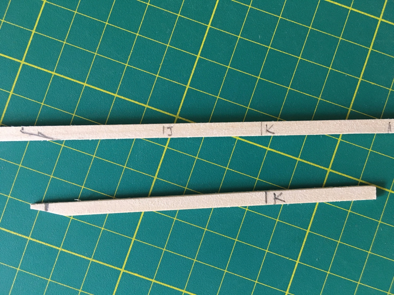
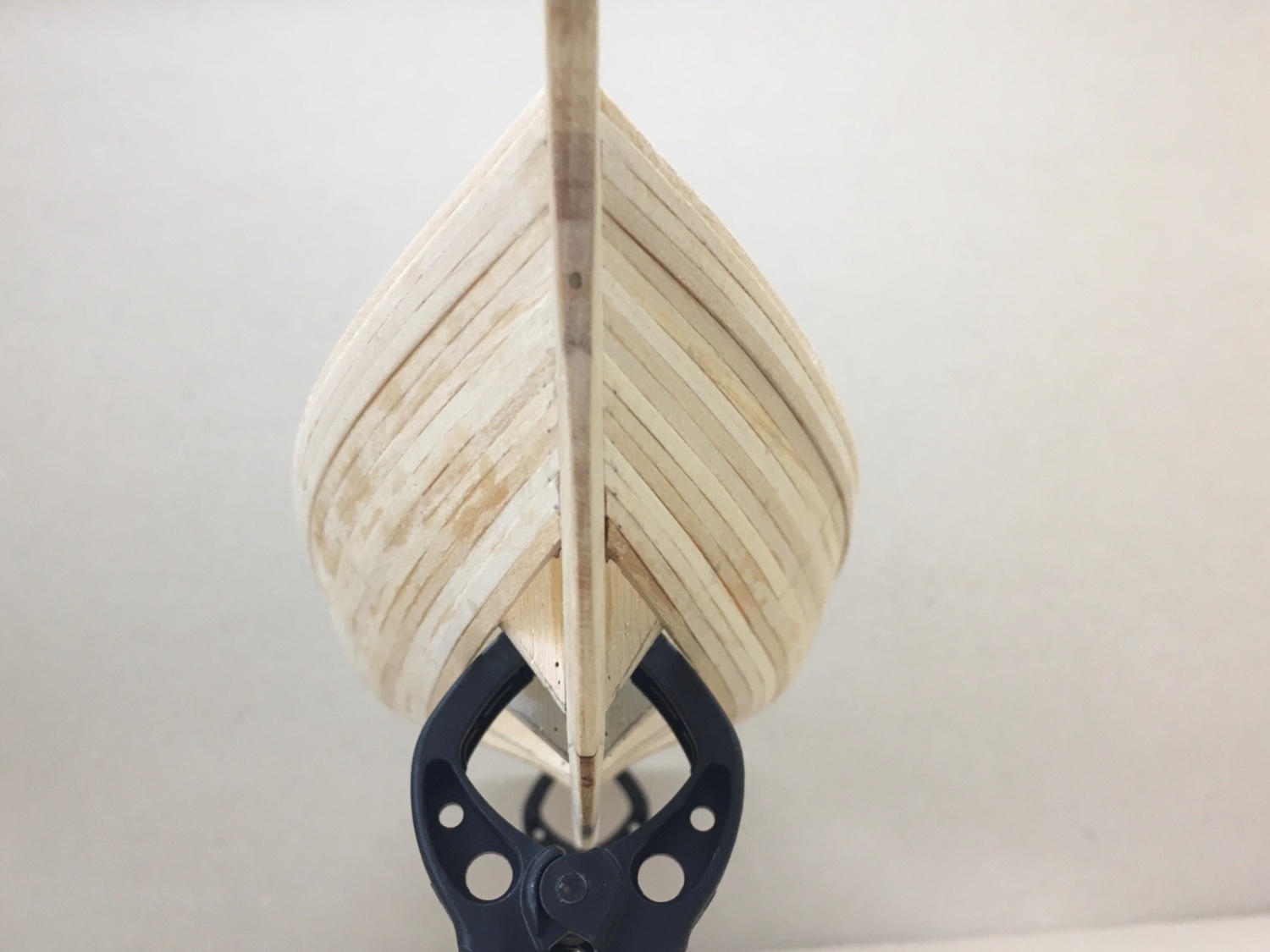
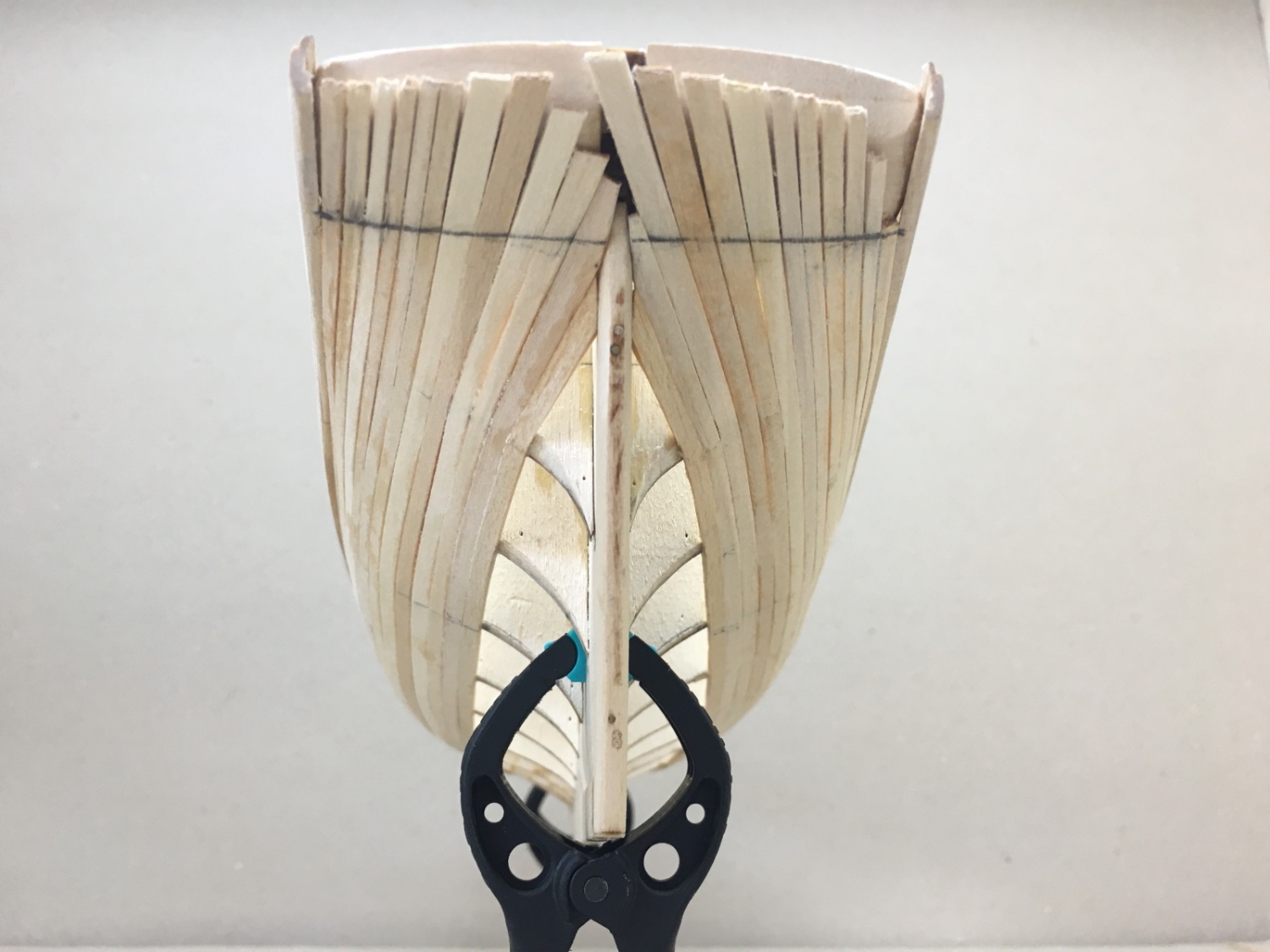
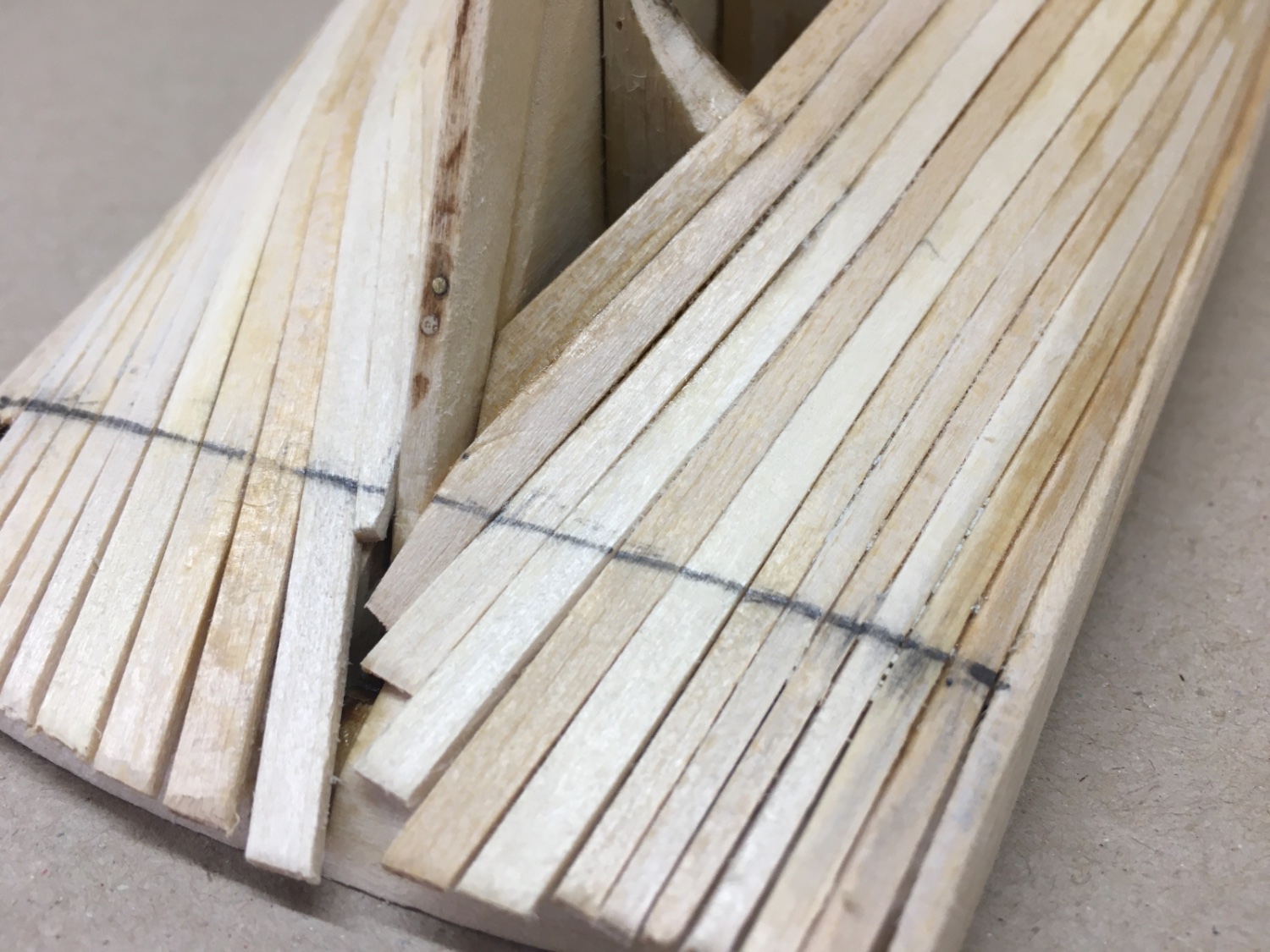
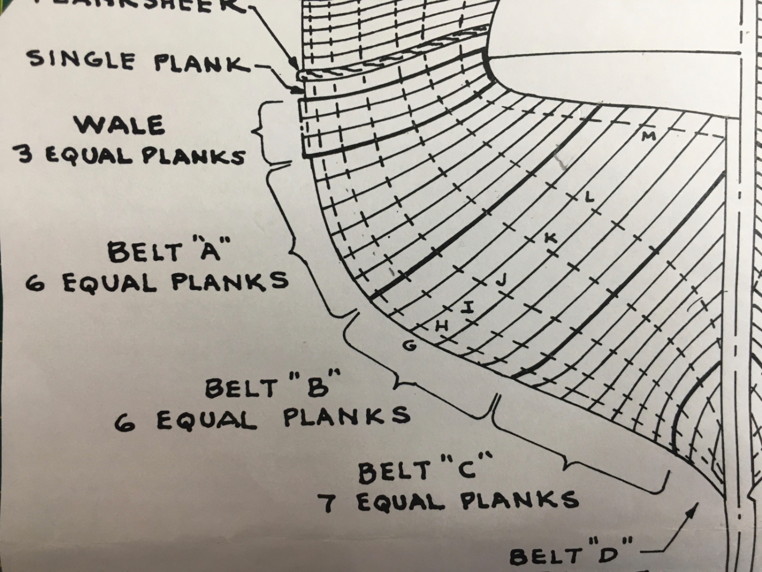
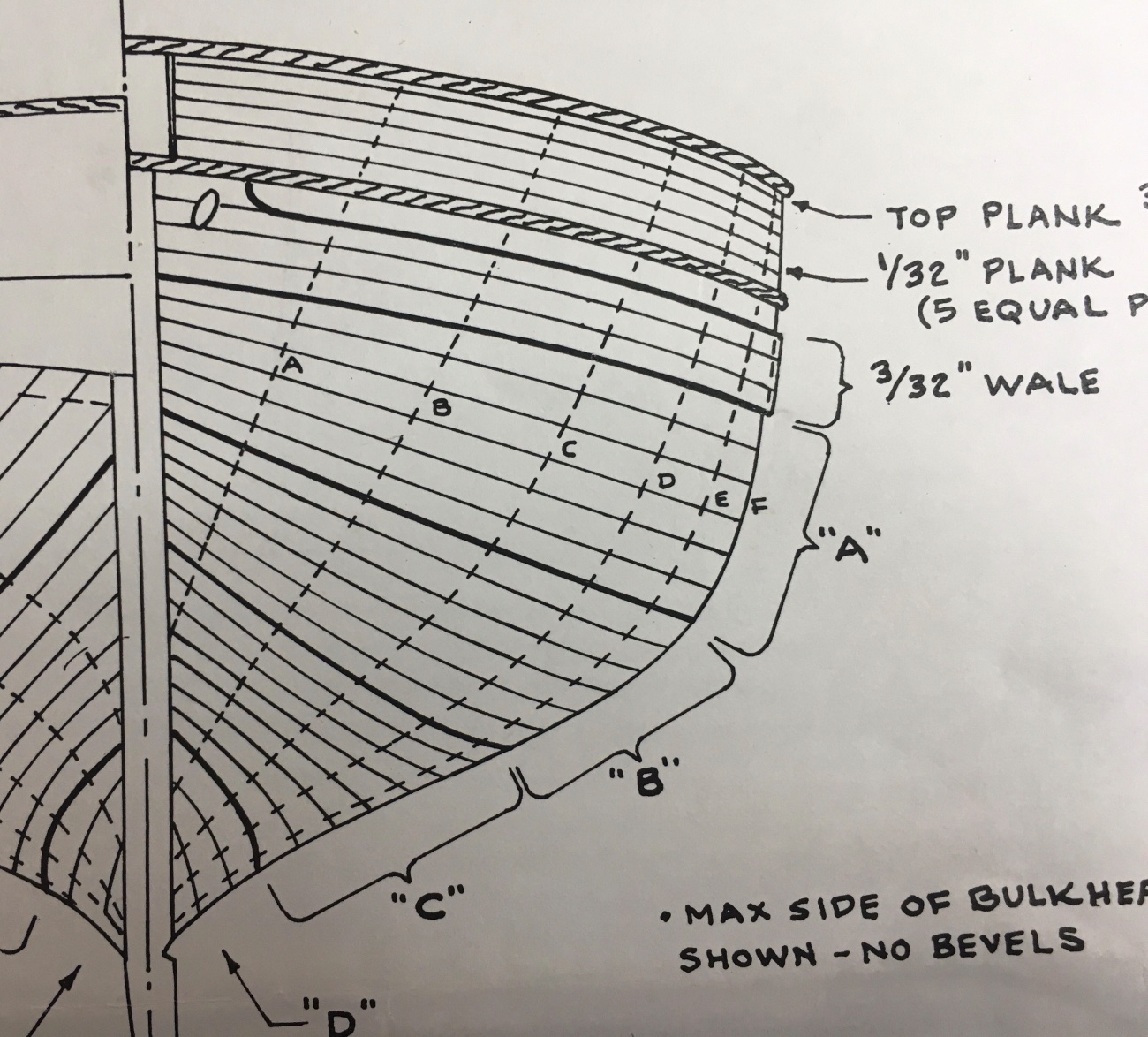
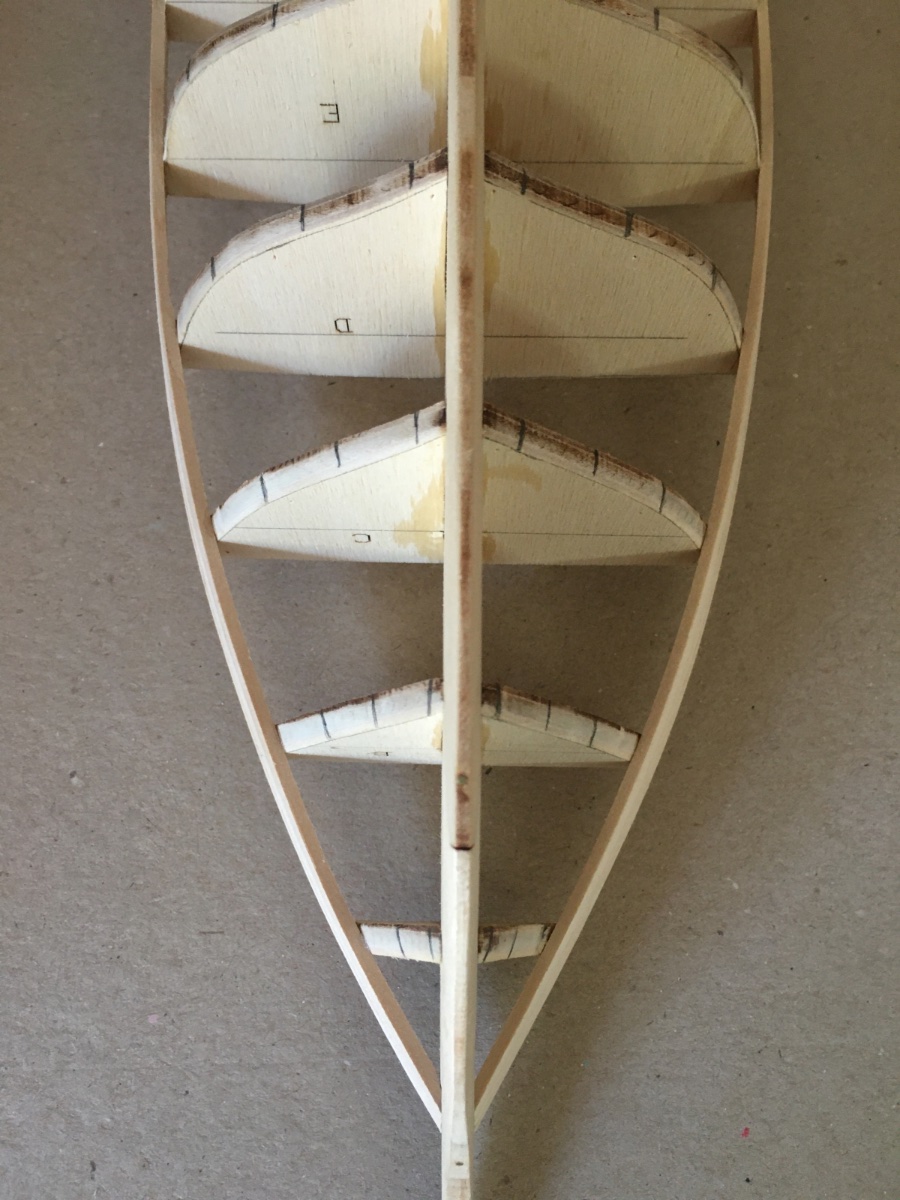
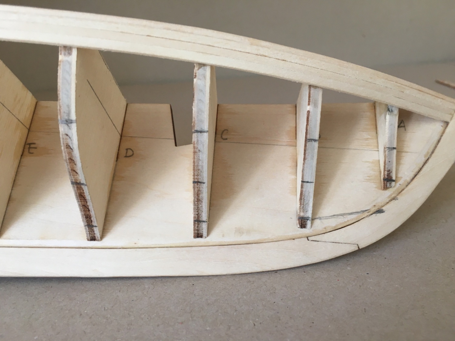
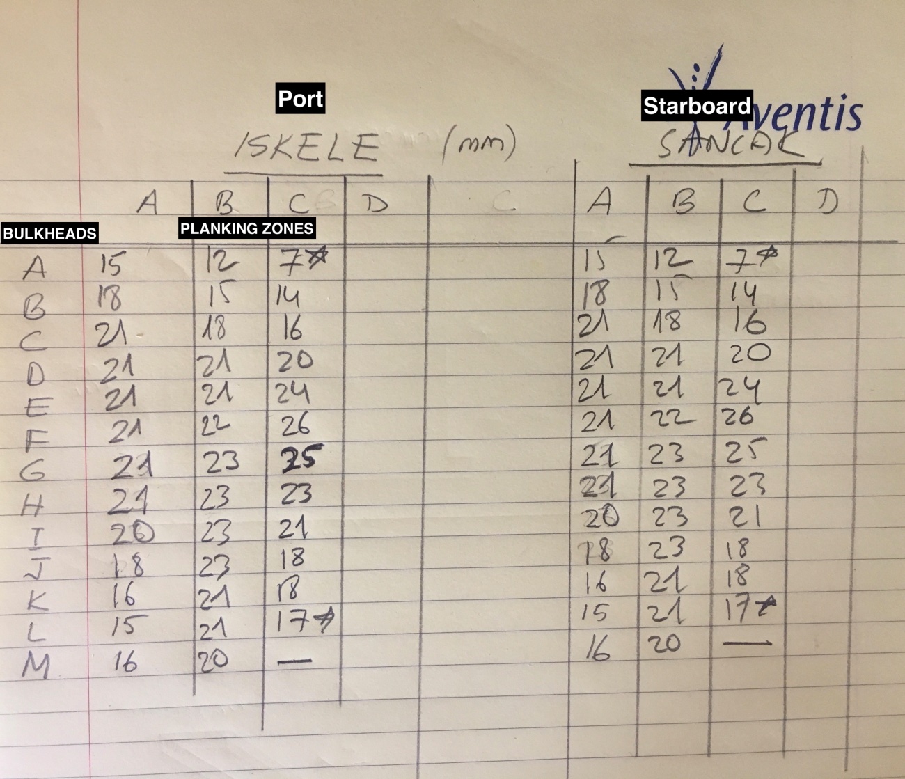
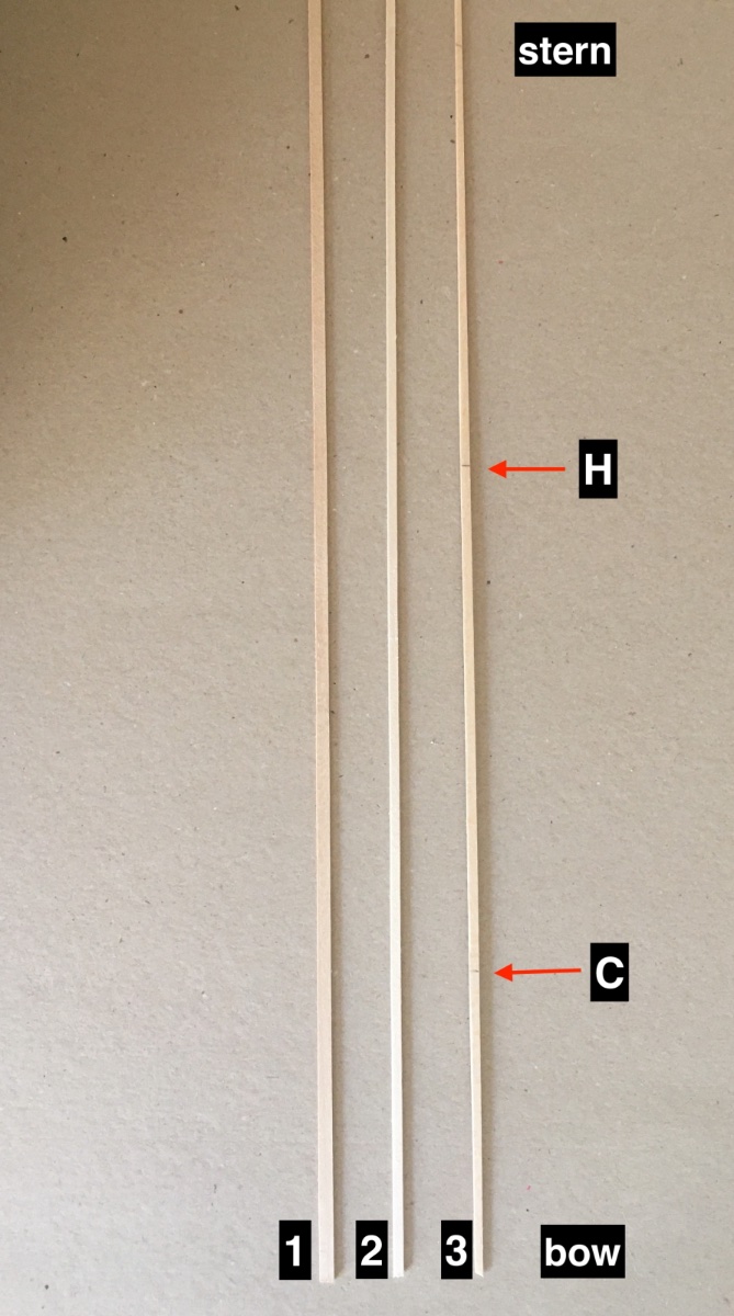
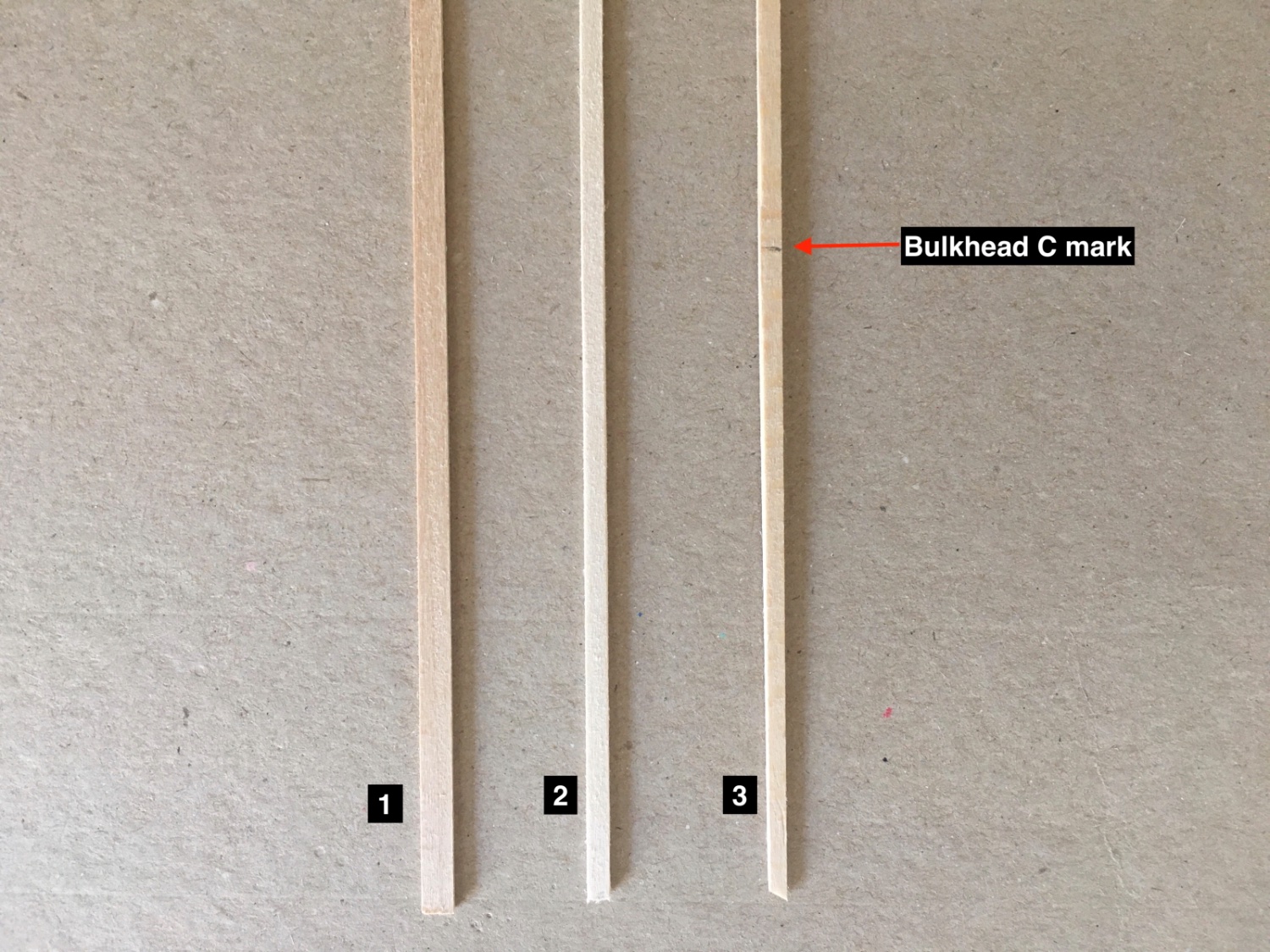
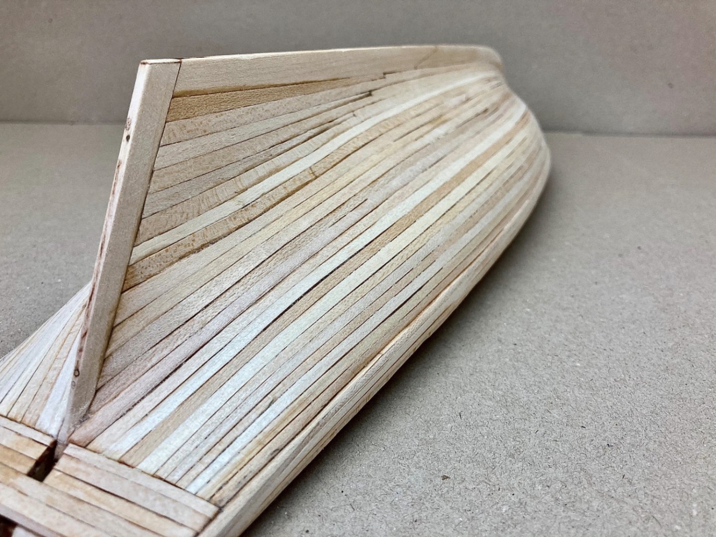
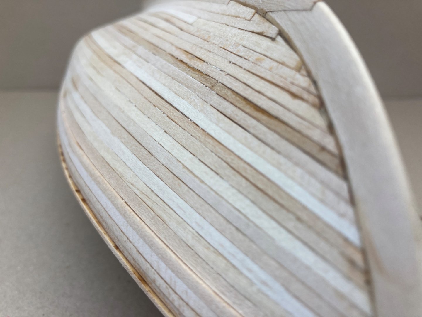
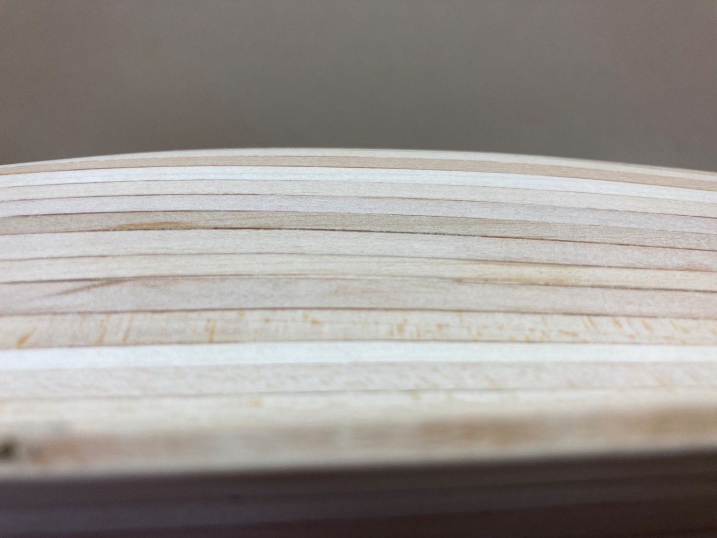
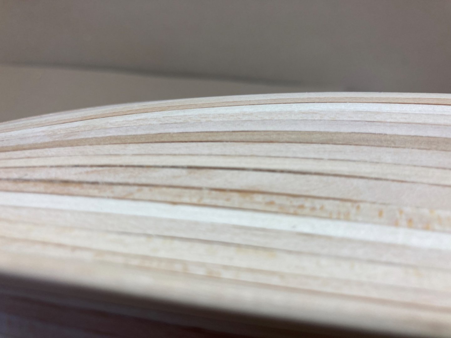
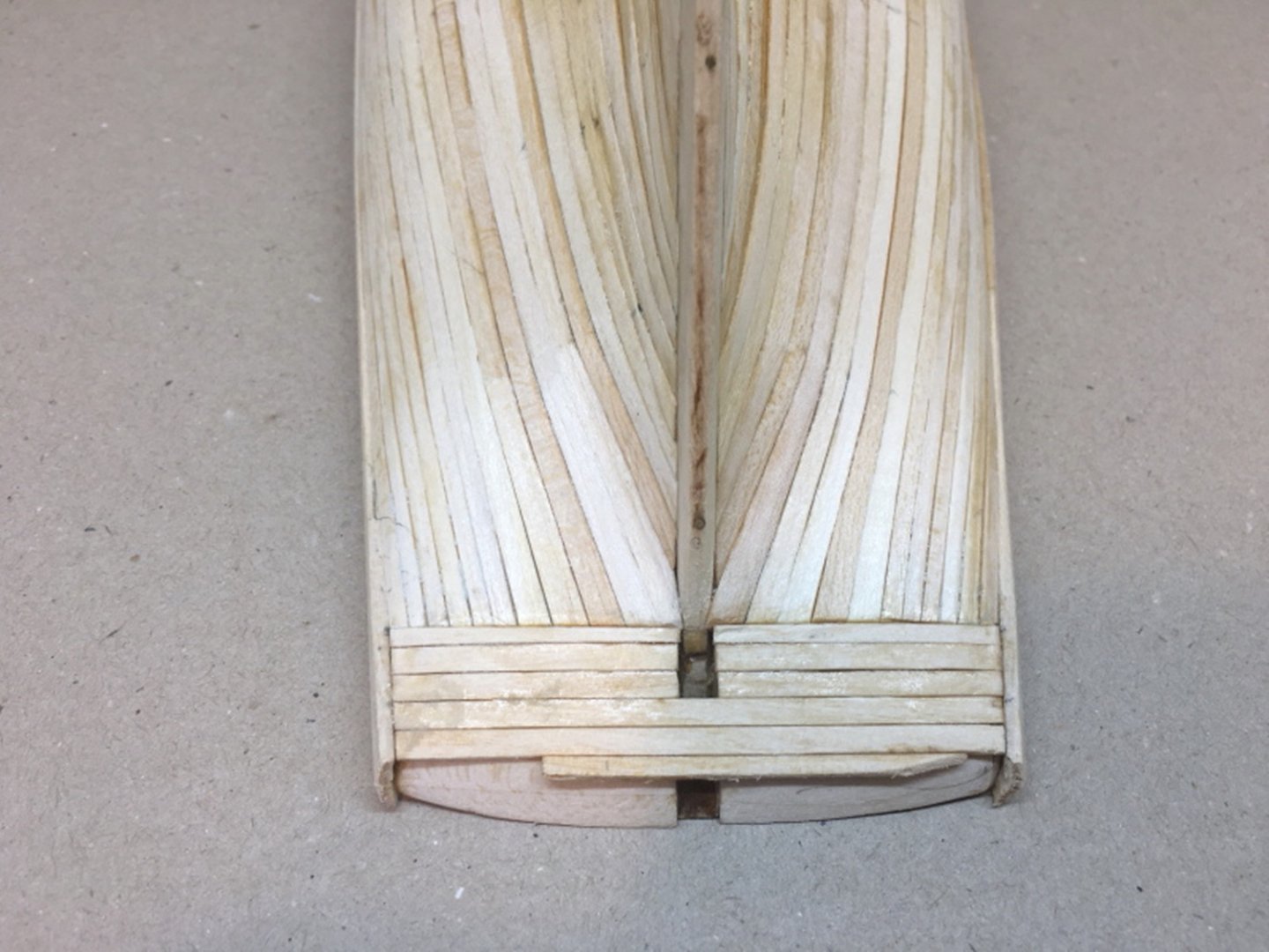
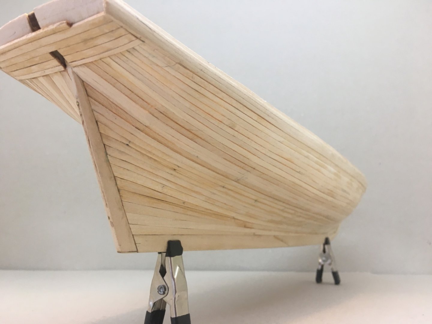
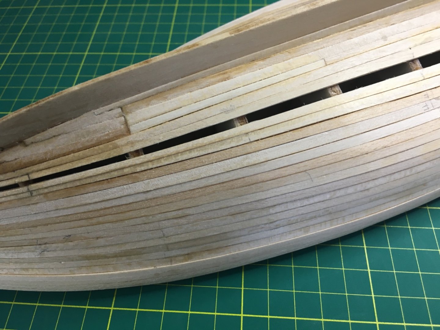
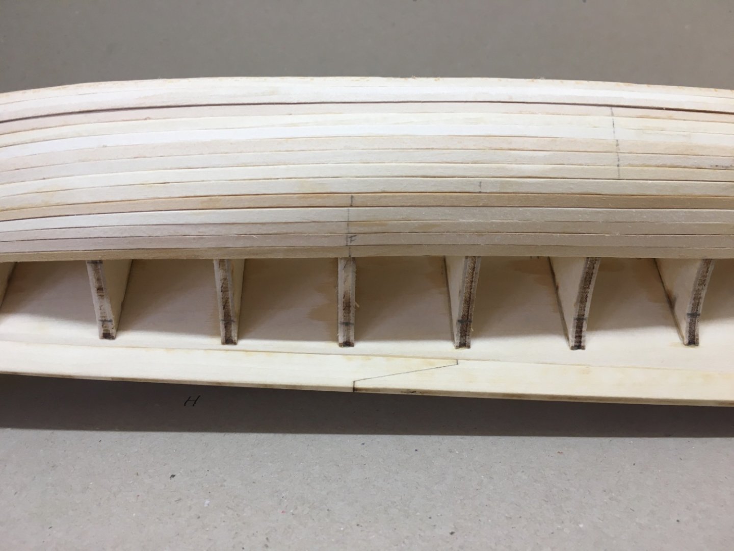
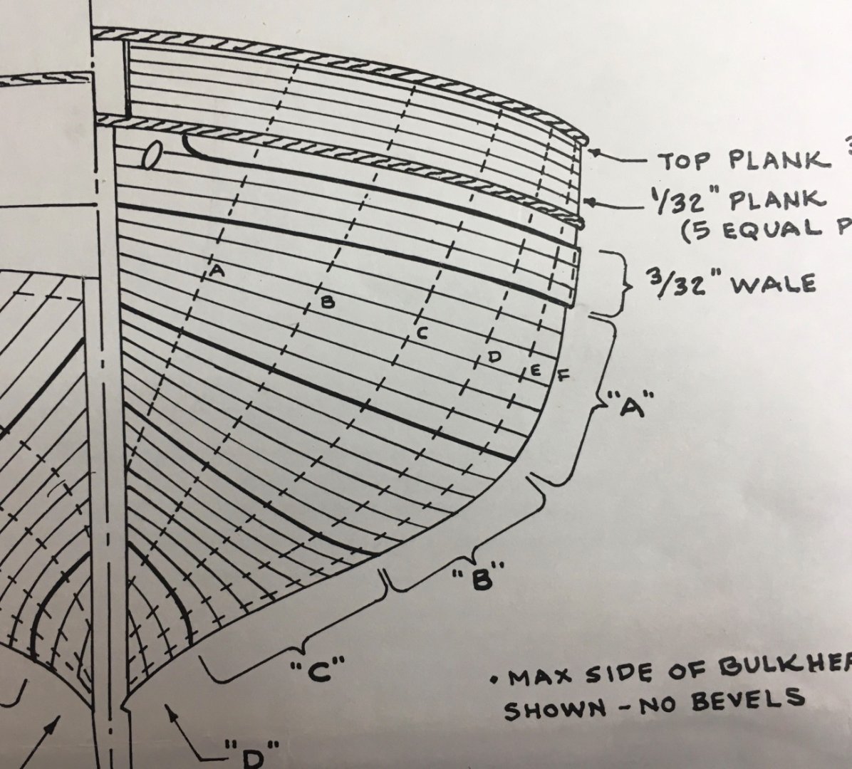
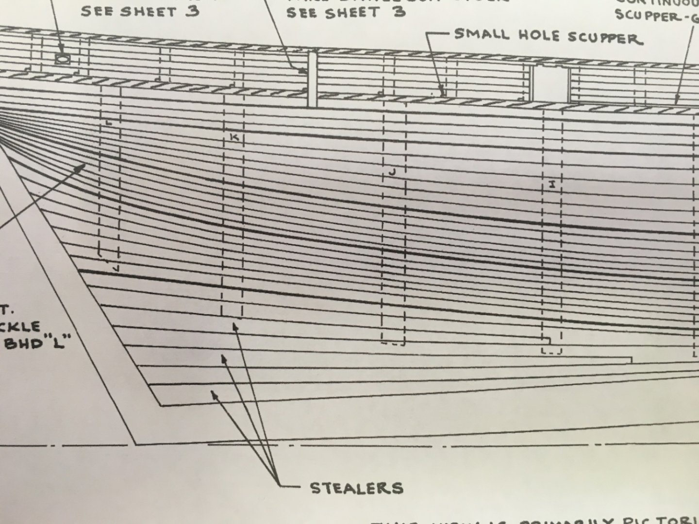
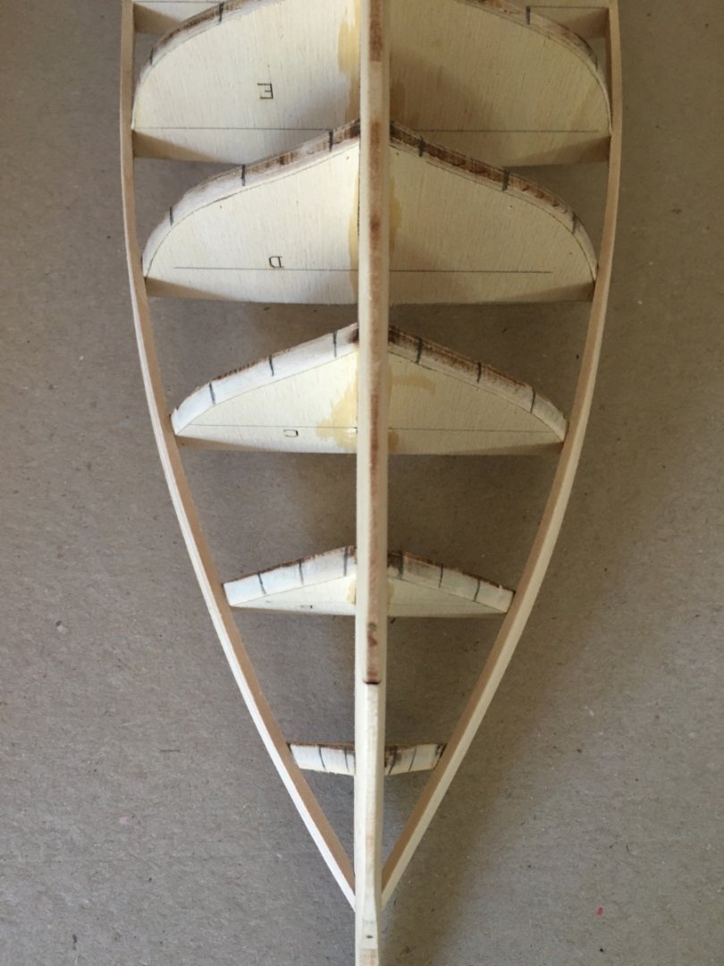
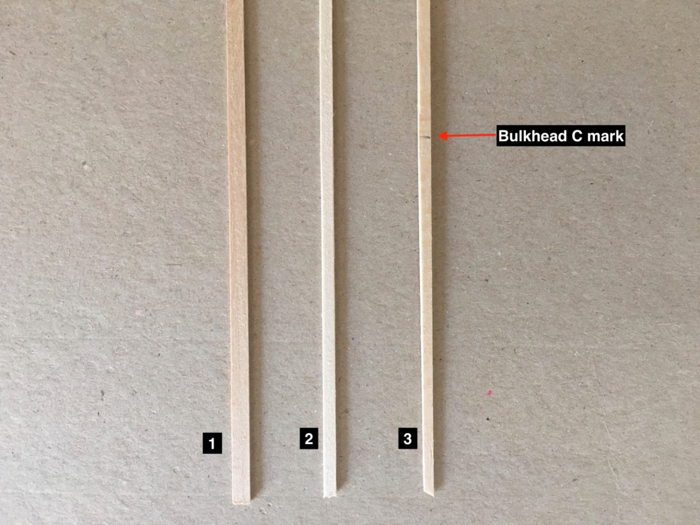
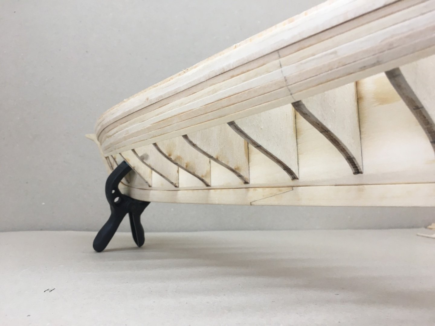
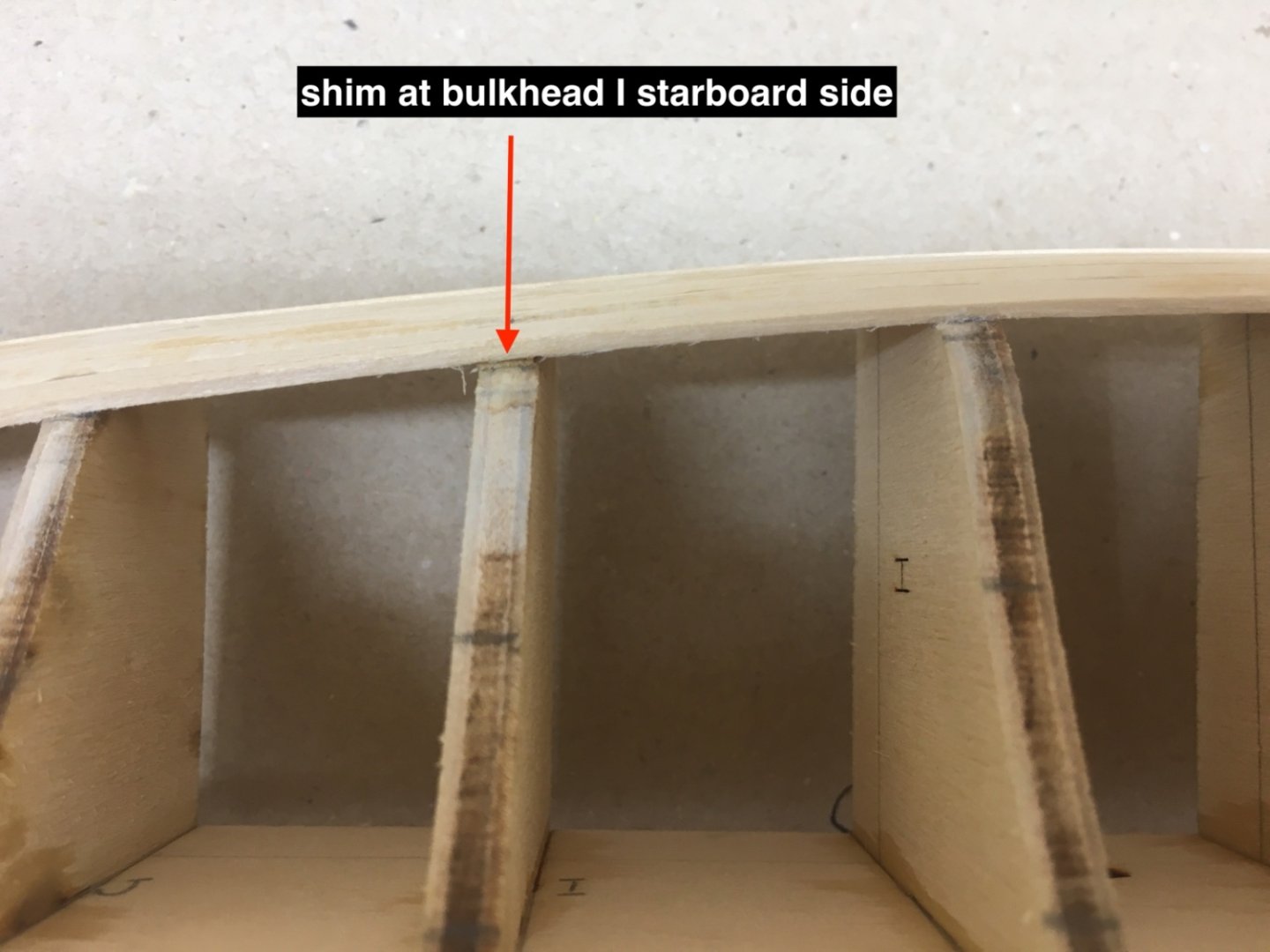
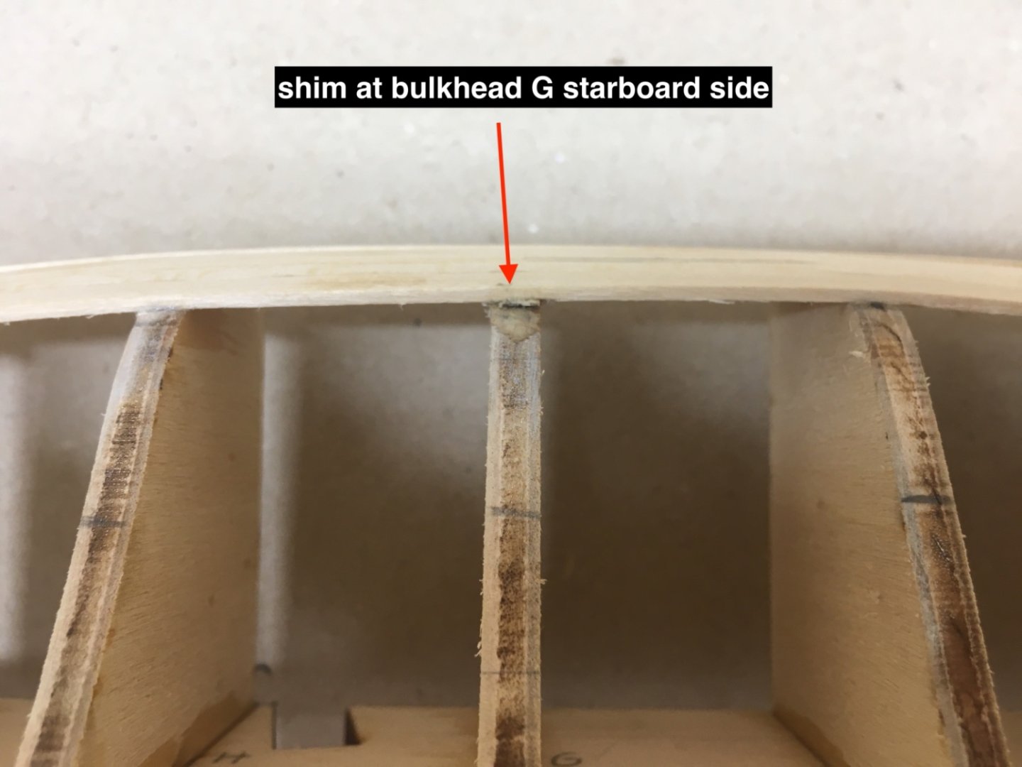
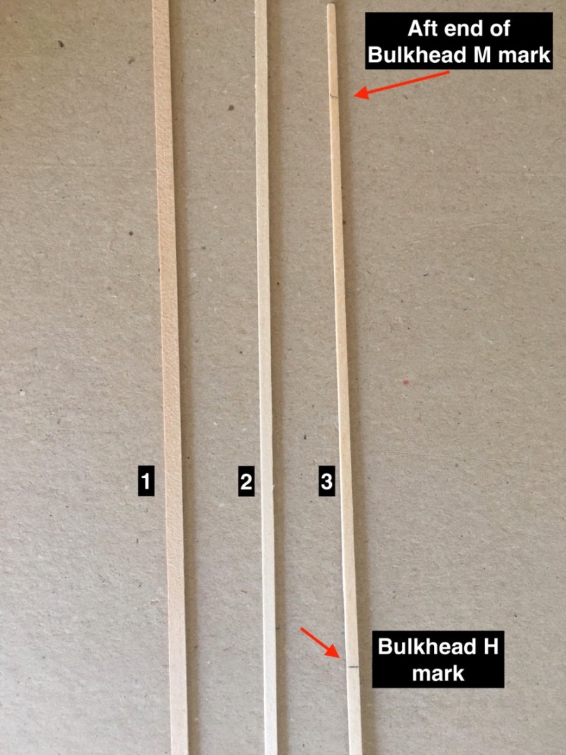
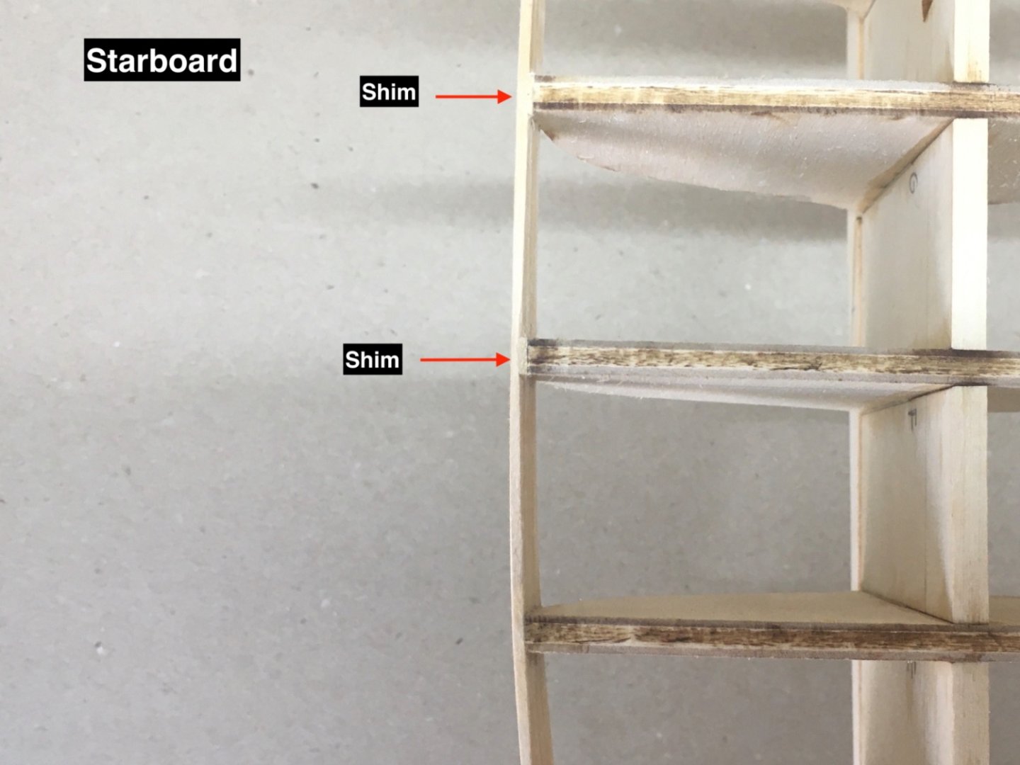
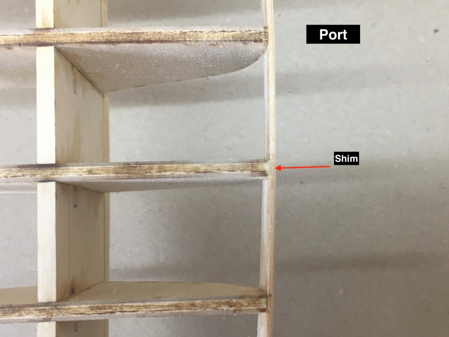
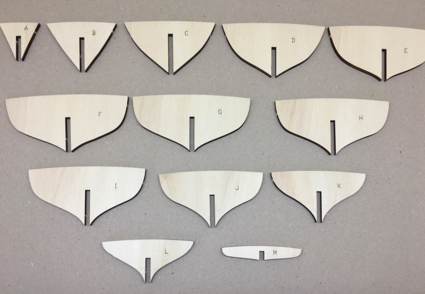
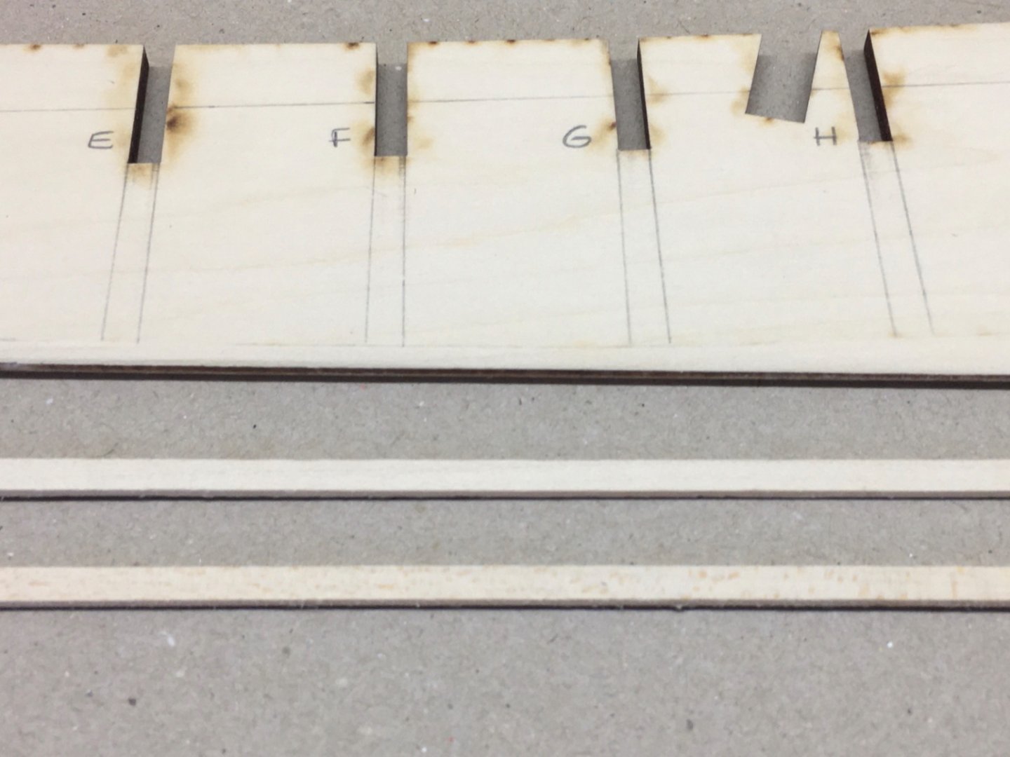
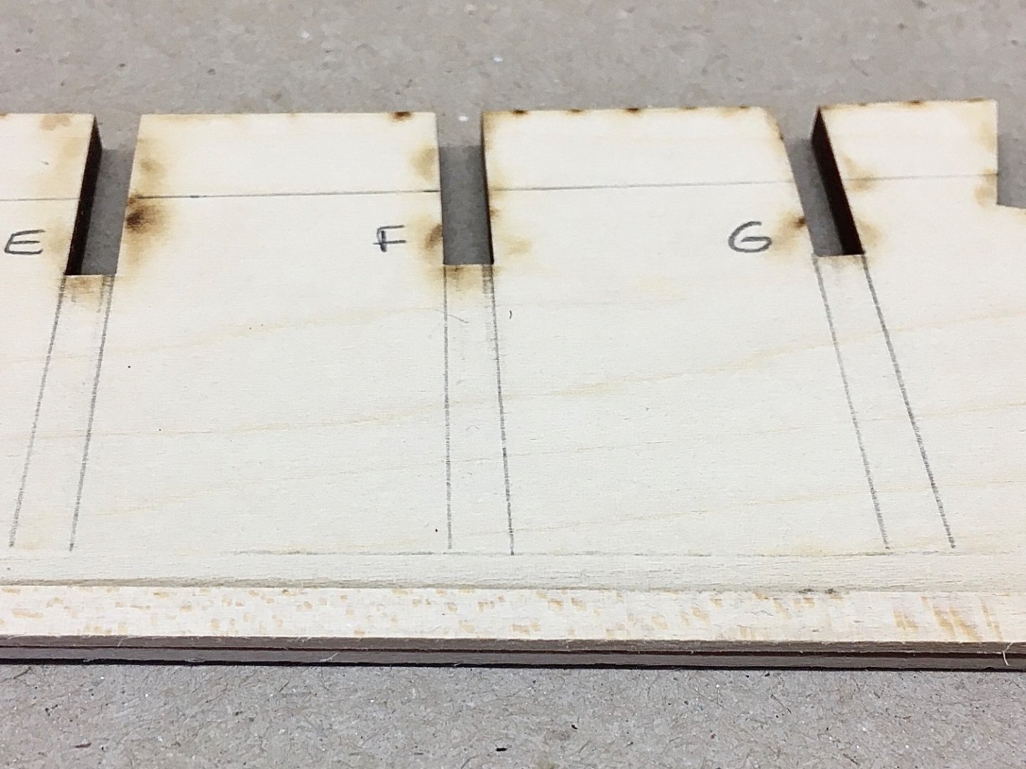
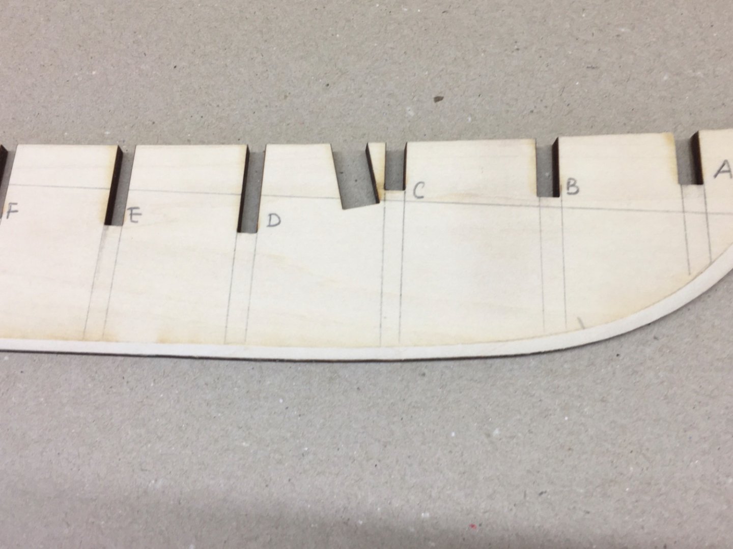
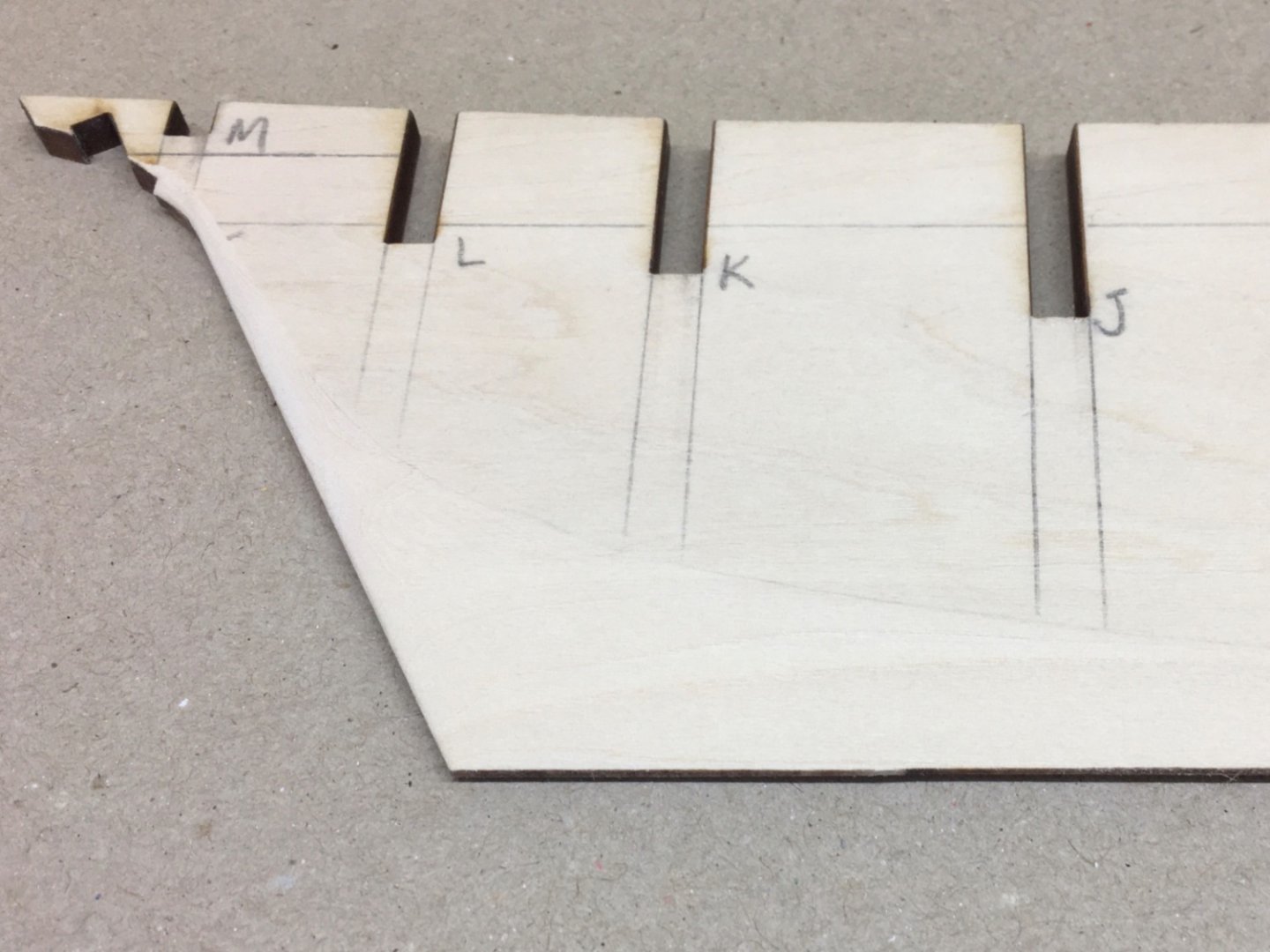
Hull planking is probably the most daunting aspect of ship building for beginners. It was no different for me. Although I finished two POB ship models before , they were pretty much straight forward builds and helped a me little for my confidence in hull planking. I was sure hull planking of POB II will be a challenging procedure. So I decided to follow the instructions and books about planking with more concentration. The ships planks are 9 inches wide. This means in 1:64 scale models planks must be around 3.5 mm and approx. 1/8 inches. However the kit's strip stock for planking is 3/16 inches or 4.8 mm . Kit instructions dictate to cut the 4.8 mm strips to 3.5 mm. 3.5 mm size is a custom size and probably impossible to find ready for selling on the shelfs. So I ordered online from a carpenter but the result was a disaster. So I decided to do the job with my Proxxon Table Saw (KS 230 'the small one') and it proved to be very satisfactory . After the planking strips were ready I carefully checked the plans. In 1:1 plans hull planking are drawn from many angles. Dividing the hull planking area into 4 zones starting from deck and towards keel , as A, B, C and D, seemed to be logical. So I measured the width of each zone on every bulkhead and noted them on paper. 1:1 plan views of hull planking Looking from stern towards forward. Bulkheads G to M Looking from Bow to aft. Planks A to F The results of measurements on paper As you can see zone D has no measurements because in zone D there are stealer and drop planks and planks have nibbed ends at fore . There are 6 planks in zones A and B and 7 planks in zone C. Zone D no number is given . Then I marked the zone borders on model at the bulkhead sides with reference to the measurements above. Almost every plank is tapered towards fore and aft. As I had the zone width measurements at every bulkhead and number of planks in that zone, the rest was simple math and a lot of fresh #11 blades and steel ruler. I like to give an example . Here is the measurement results again. In zone A , zone width from bulkhead C to bulkhead H is the same, 21 mms. If you divide 21 by the number of planks in that zone, which is 6, you get the result 3.5 mm. 3.5 mm is the width of our new already cut strips. That means planks in zone A do not need tapering between bulkheads C and H. You mark the bulkheads C and H on the strip. Then you mark the bow end first. At bulkhead head A zone A width is 15 mms. When you divide 15 mm by the planks number in that zone which is 6 you get the result 2.5 mms. That means at bulkhead A mark plank must be 2.5 mm wide. That 2.5 mm is marked on the plank. Then you mark the bulkhead M on the strip. At bulkhead M zone width is 16 mms , almost the same as bulkhead A. So you can mark 2.5 mm on the aft end of the strip this time. Now you are ready to taper. Always use a steel ruler and a fresh #11 knife. One more important factor is to taper and cut the planks NOT on the sides which neighbors the previous plank BUT on the side which will be free. From that point on the procedure is repeated for every plank installed. In the pictures below 1 is kit's stock strip, 2 is our cut strip and 3 is tapered strip. I started planking in zone A and followed the B,D and finally C order. Planking is done by alternating between port and starboard sides and doing two planks on each side at a time. In zone A you can see that the aft ends of the planks pass the bulkhead M and lay on counter blocks. These are to be cut off later at the aft border of bulkhead M. Here are pictures of planks in Zone A. At two locations shimming was necessary. Bulkheads I and G at starboard side. One more note before the next post. Although the hull was going to be painted finally and many of the planking mistakes can be covered , I tried to follow the book and tried to do the job as if the finishing would be bare wood without any paint. By doing so I believe one's planking skills will increase. Next post will be planking of the rest of the zones.


- 114 replies
-
- 4
-
-
- Pride of Baltimore II
- Model Shipways
- (and 1 more)
-
Hello Yves, I am very honored with your thoughts. I consider myself like a humble sophomore in scale modeler collage as a model builder , among so many junior and seniors. Also there are quite a number of post-graduates . I like documenting and sharing my experience which I believe is a habit acquired during my professional life as an MD and a teaching surgeon of Otolaryngology and now in the days of retirement I simply follow it in a different subject. During my built of POB II , finding a detailed and comprehensive build blog was very hard and there were only a couple of good ones. I believe the retrospective blog I started will be interesting, because when some modeler sees and likes a finished ship model in the gallery , he or she will probably be interested in the building process of it especially if building that ship model is in his or hers future plans. And if this blog helps and hopefully satisfies even only one modeler then I ‘ll be more than happy. For the coming two months I will be in Ankara and away from the workshop. Posting daily will be like a winter hobby to me. Have a nice day Halit
- 114 replies
-
- 2
-
-
- Pride of Baltimore II
- Model Shipways
- (and 1 more)
-
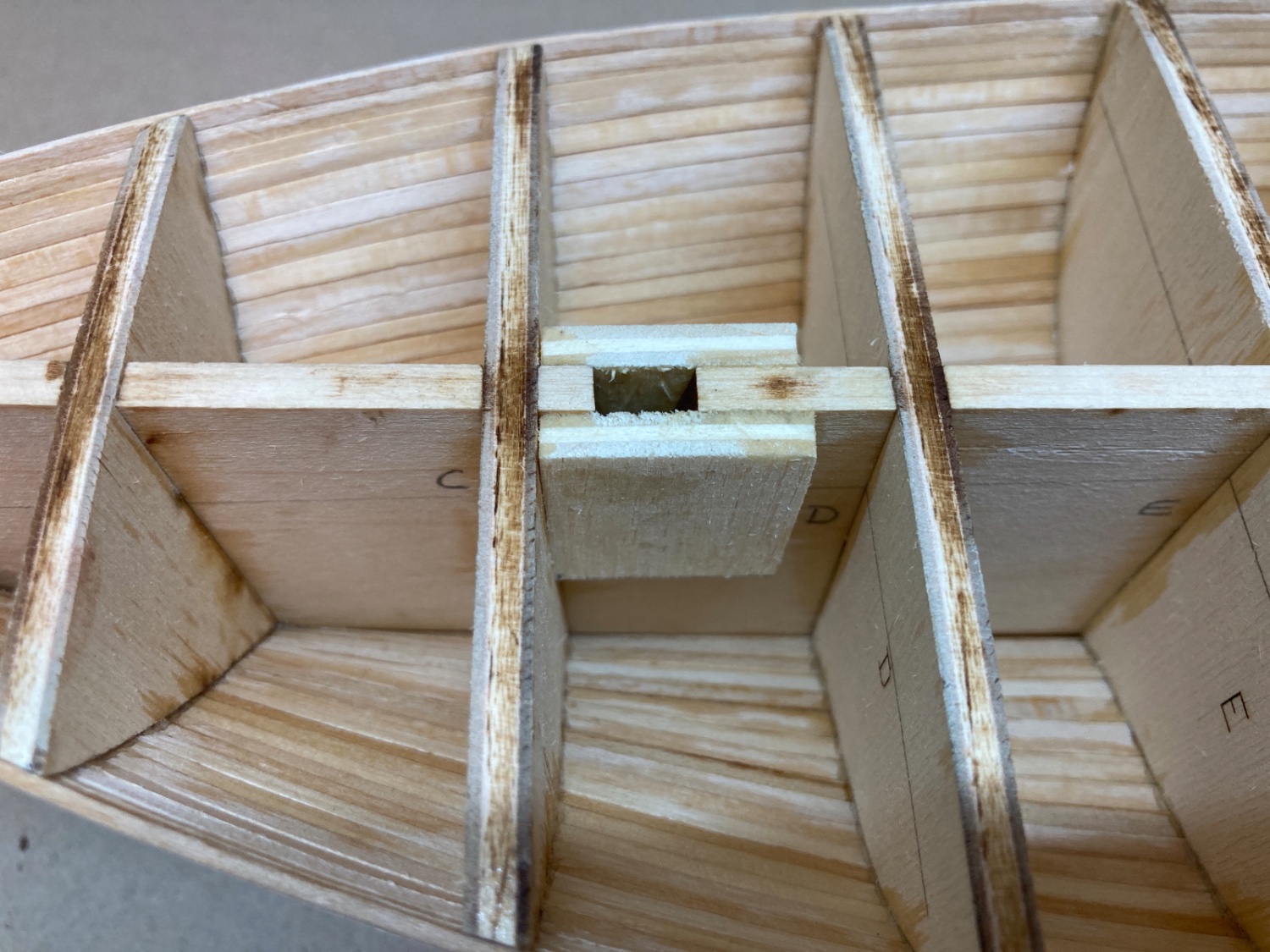
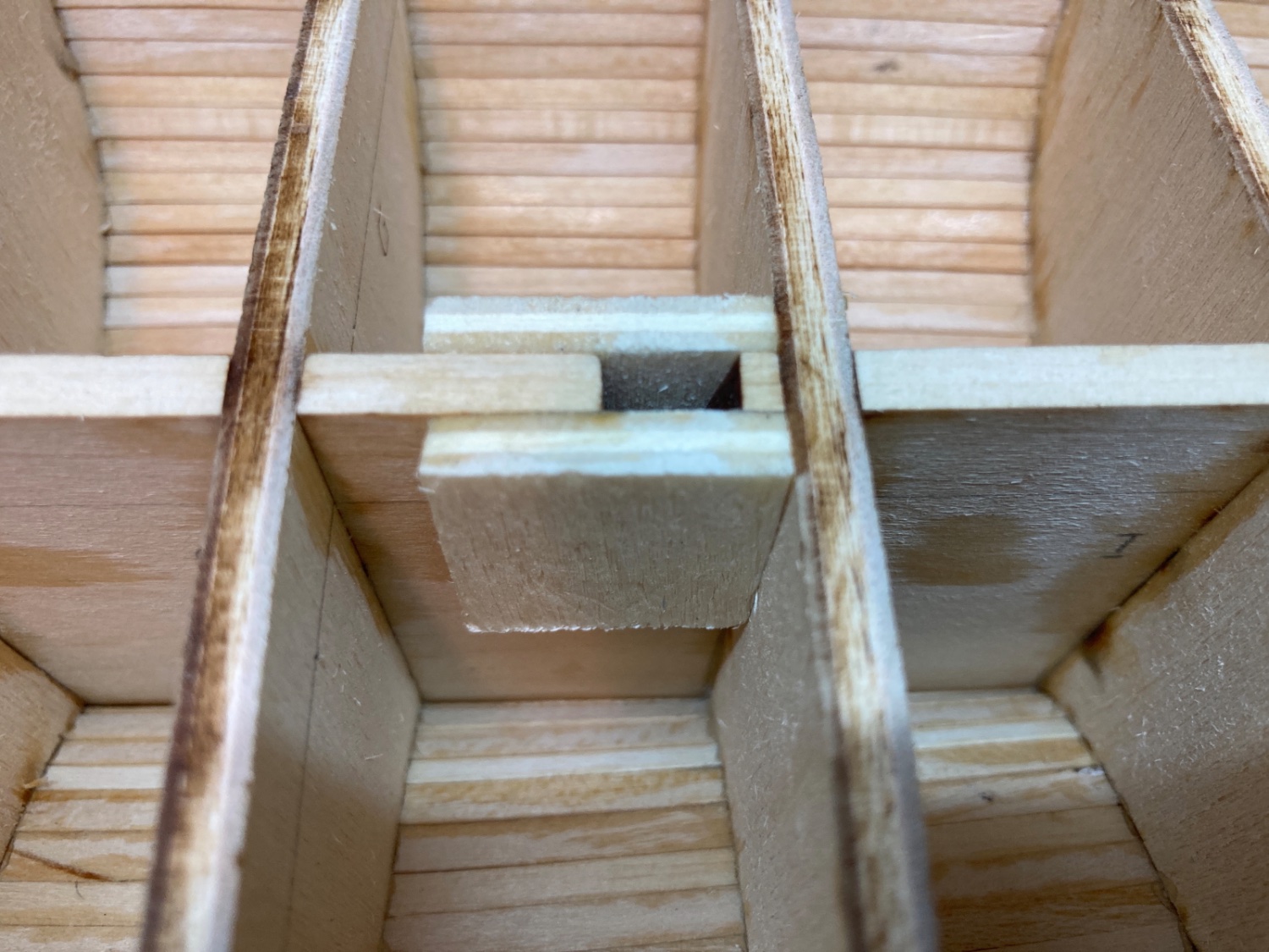
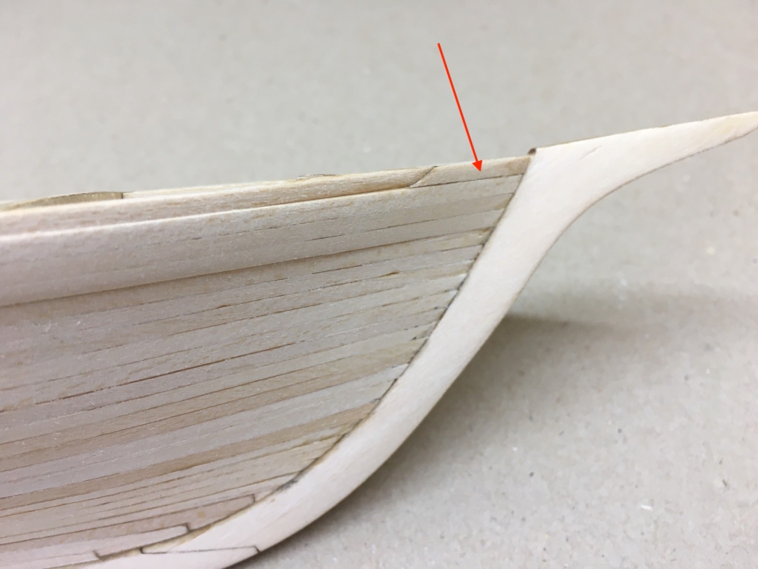
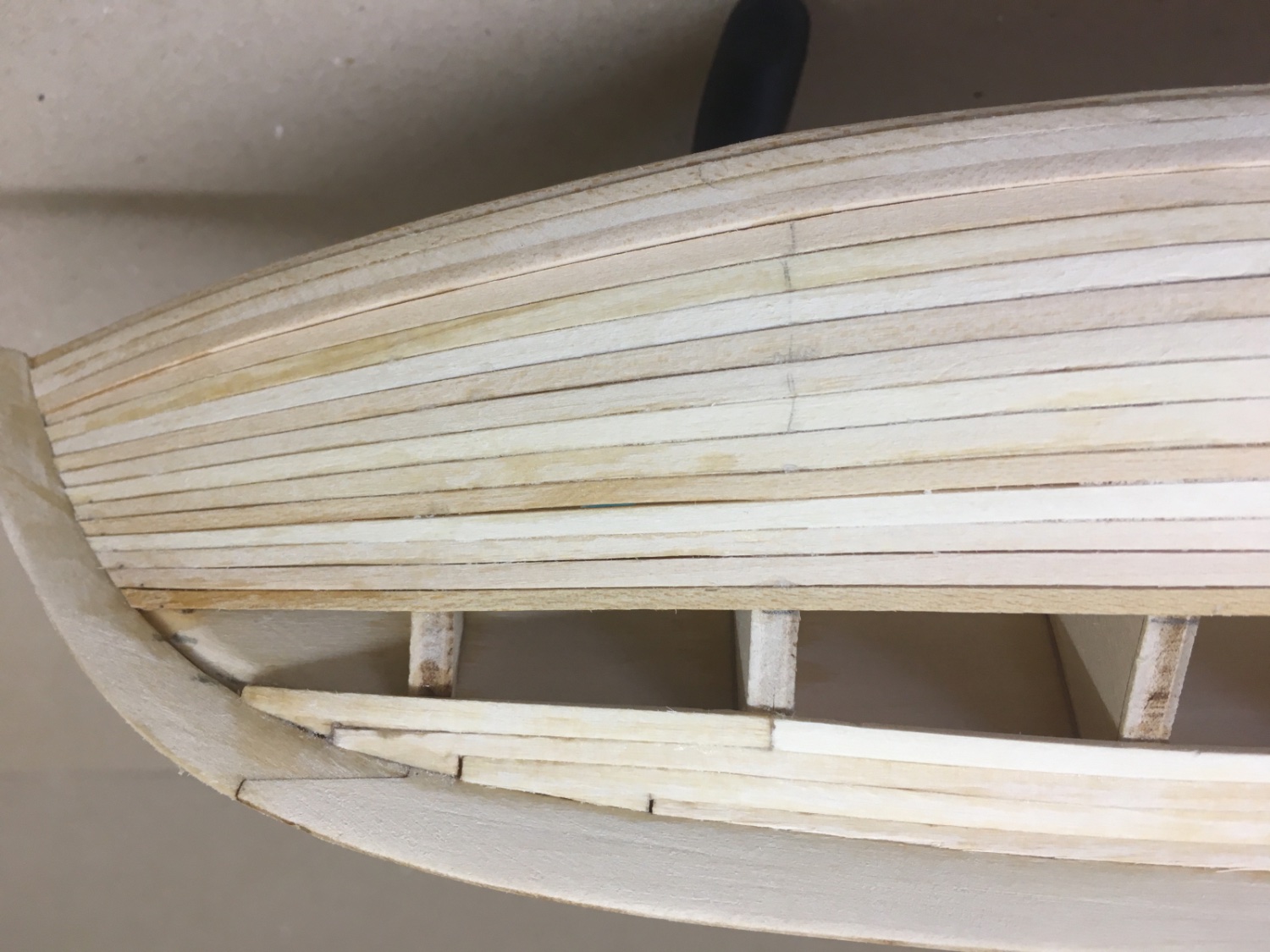
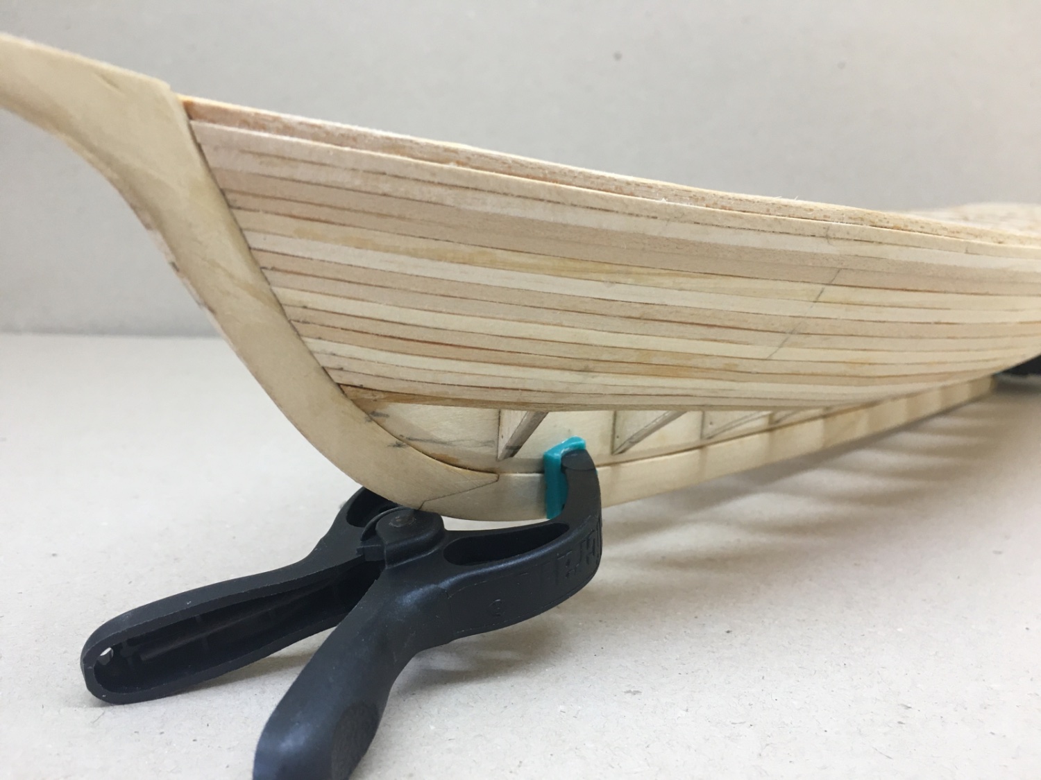
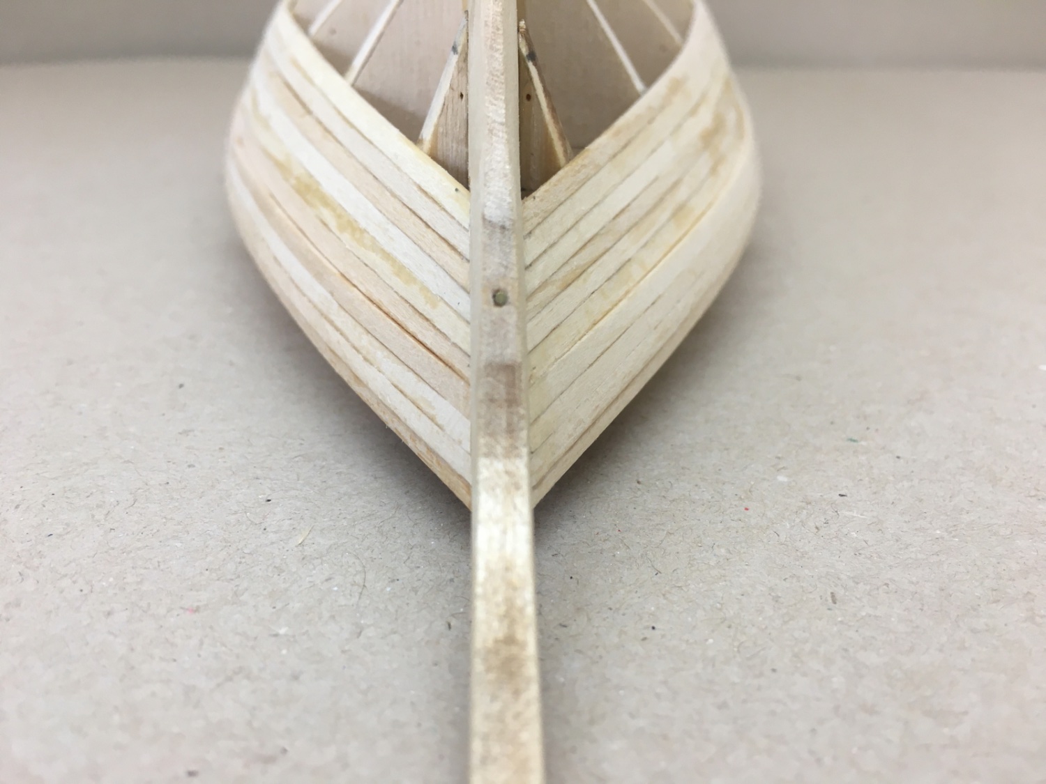
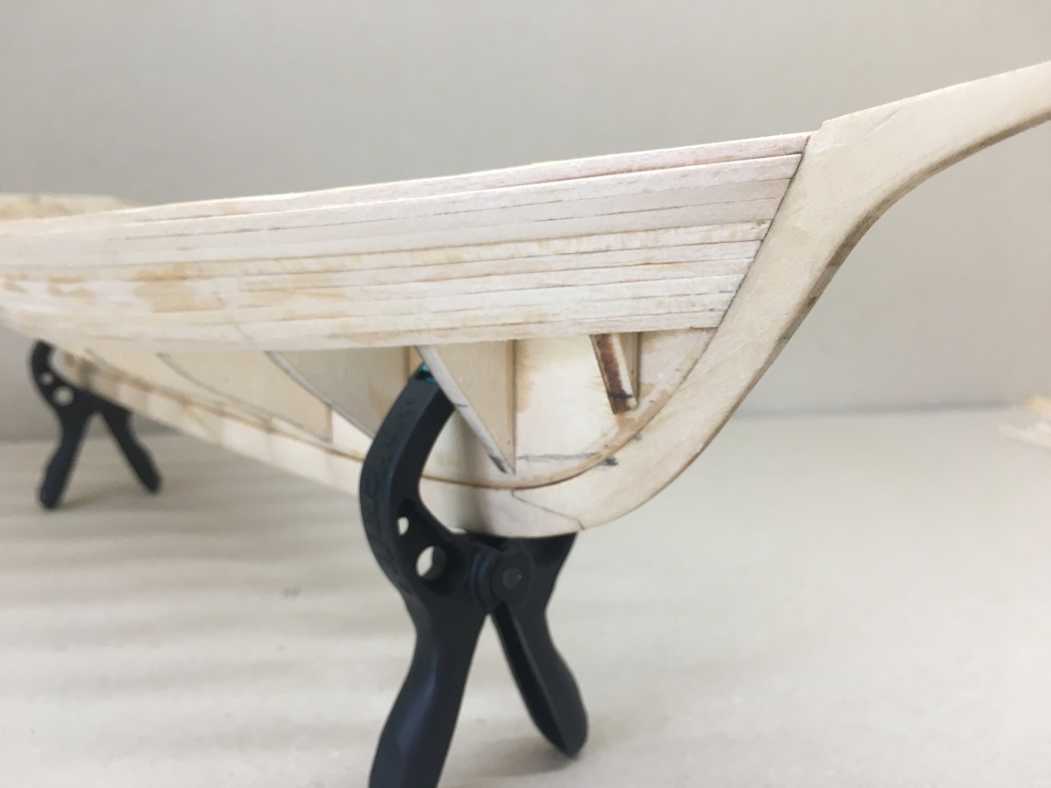
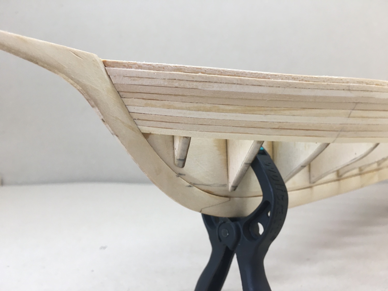
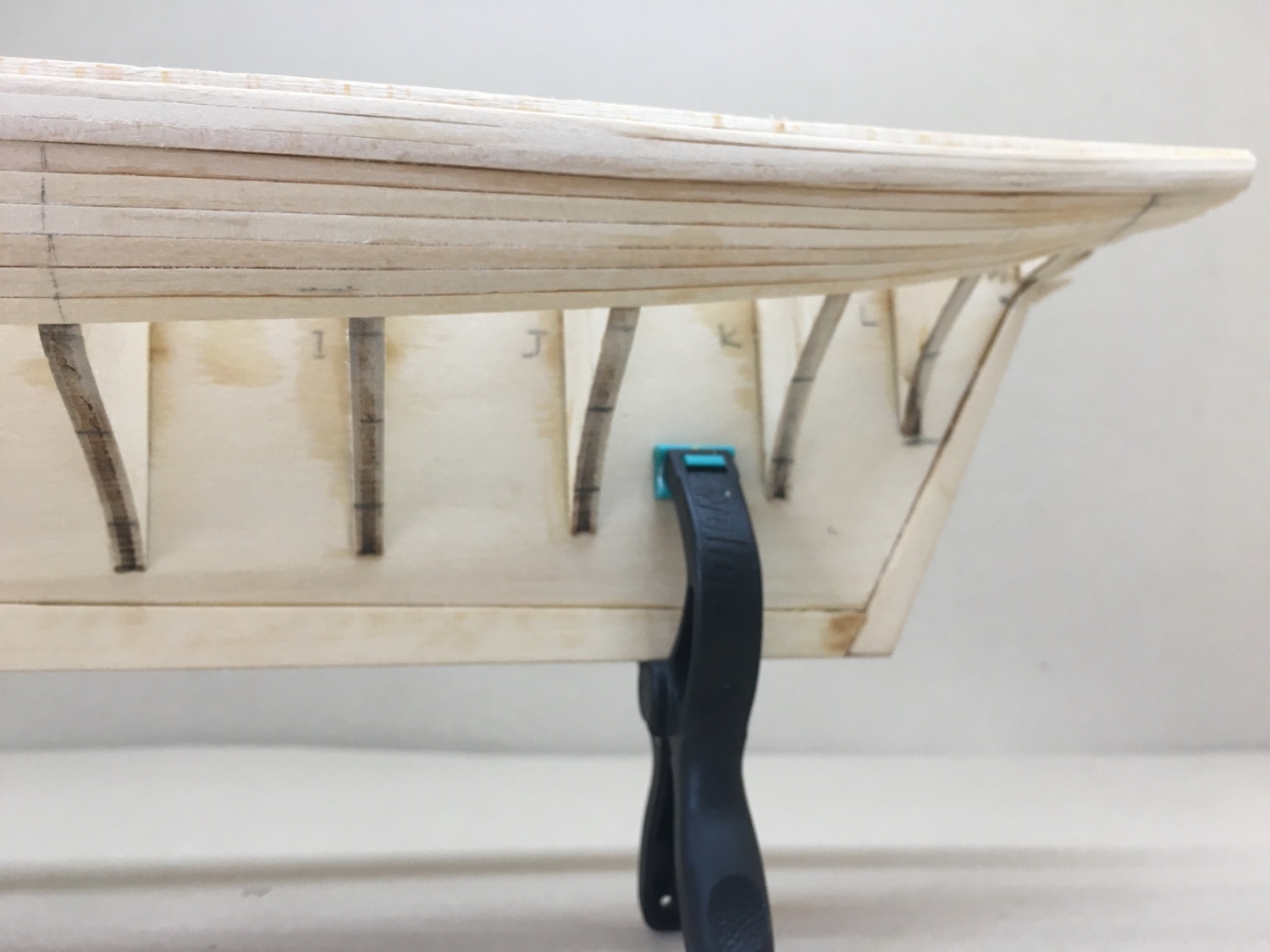
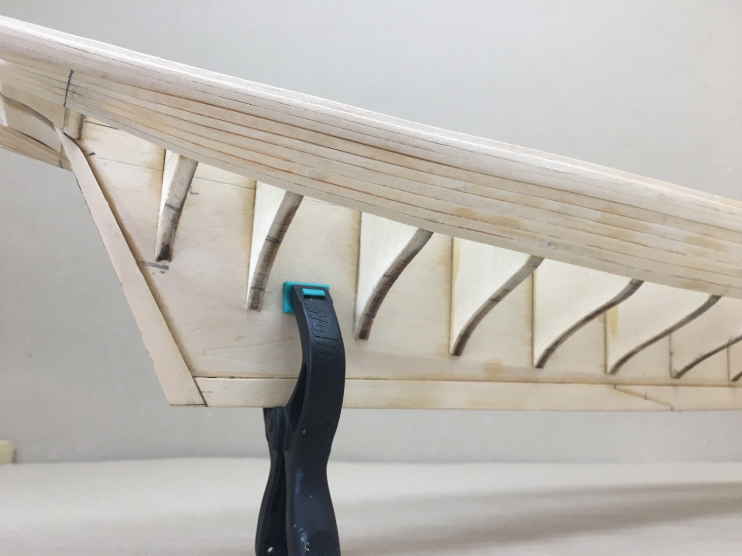
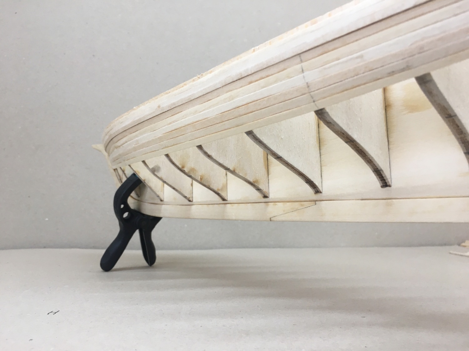
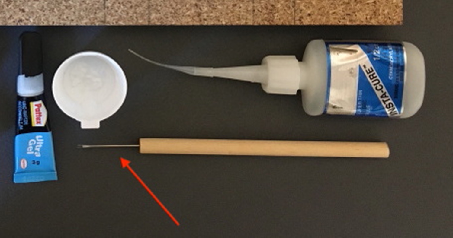
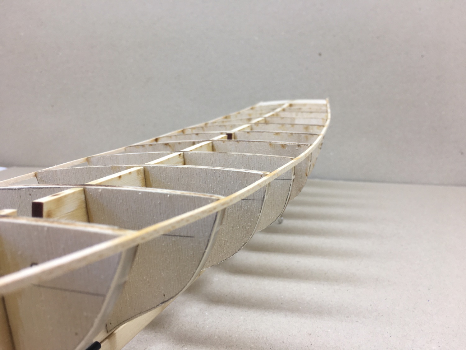
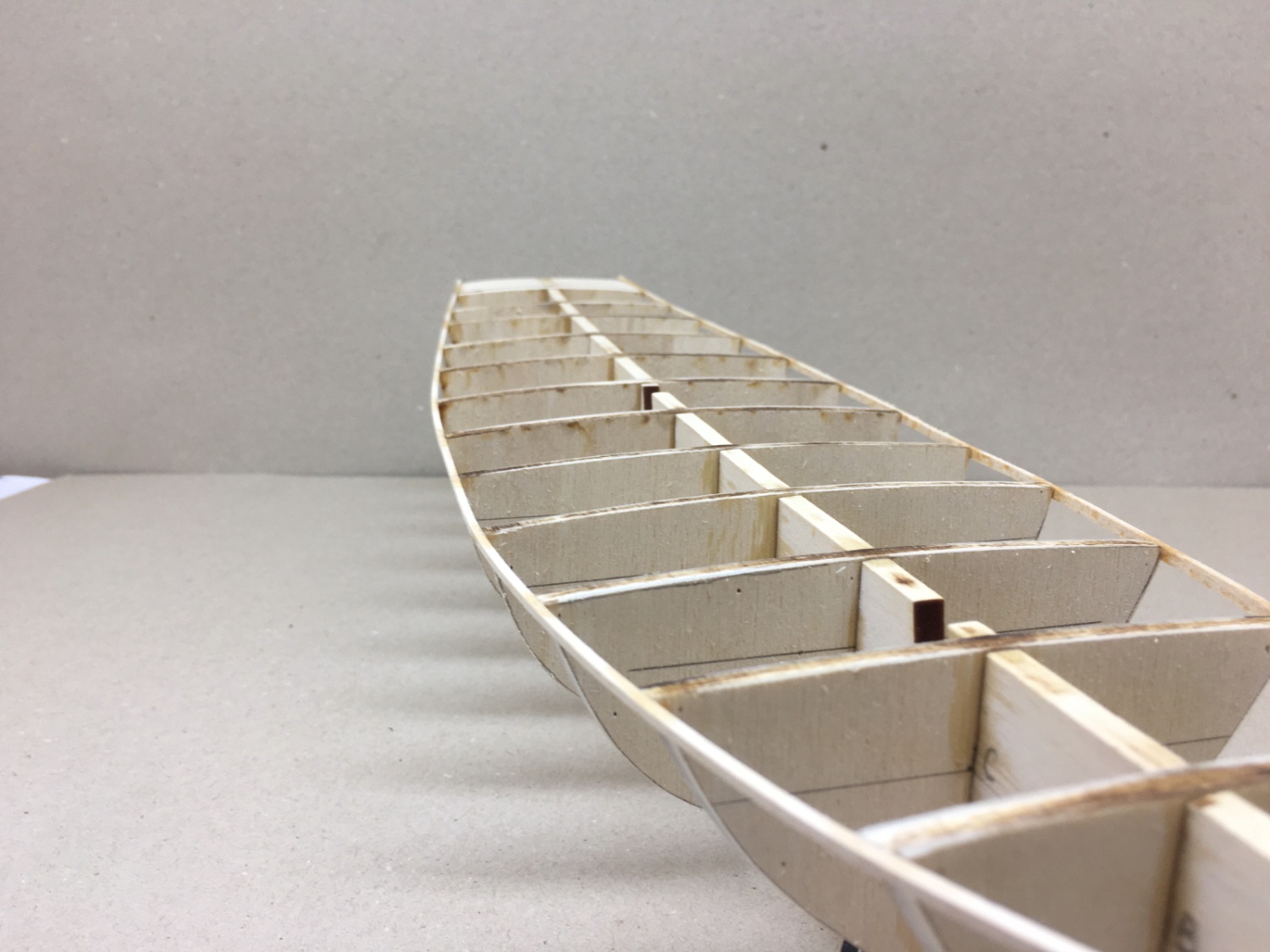
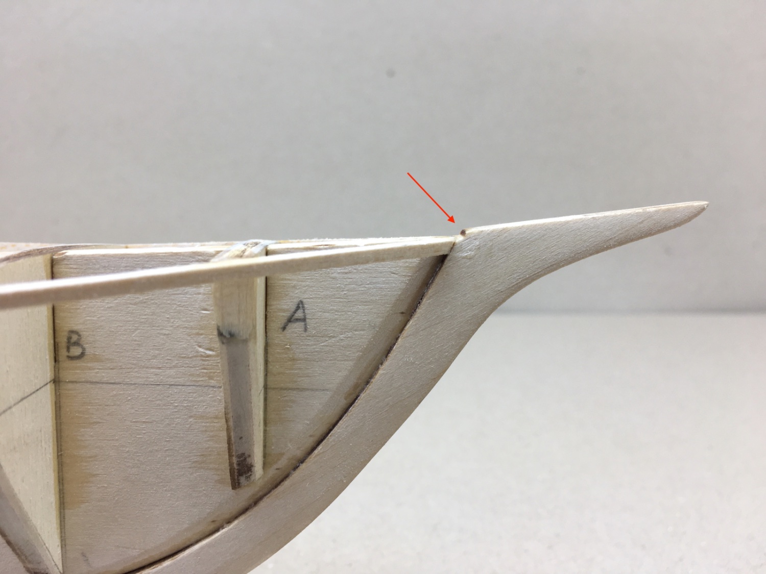
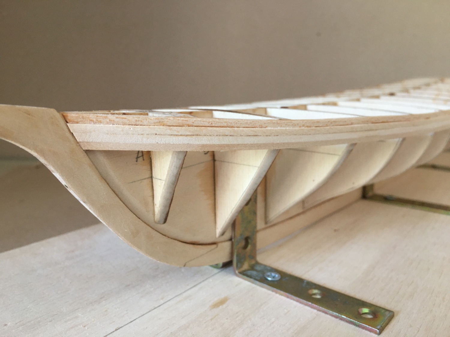
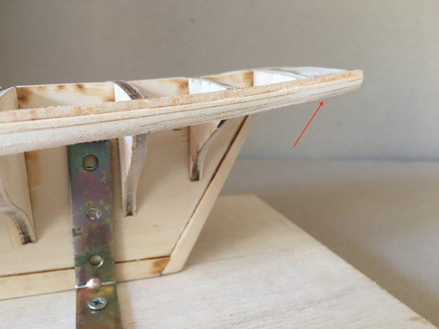
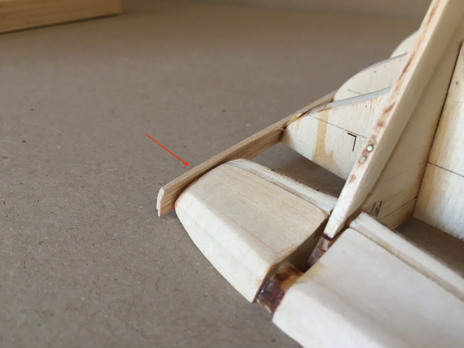
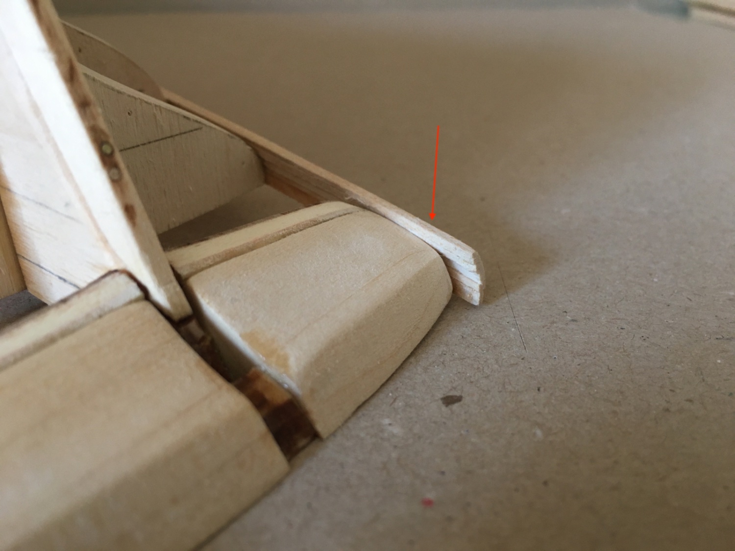
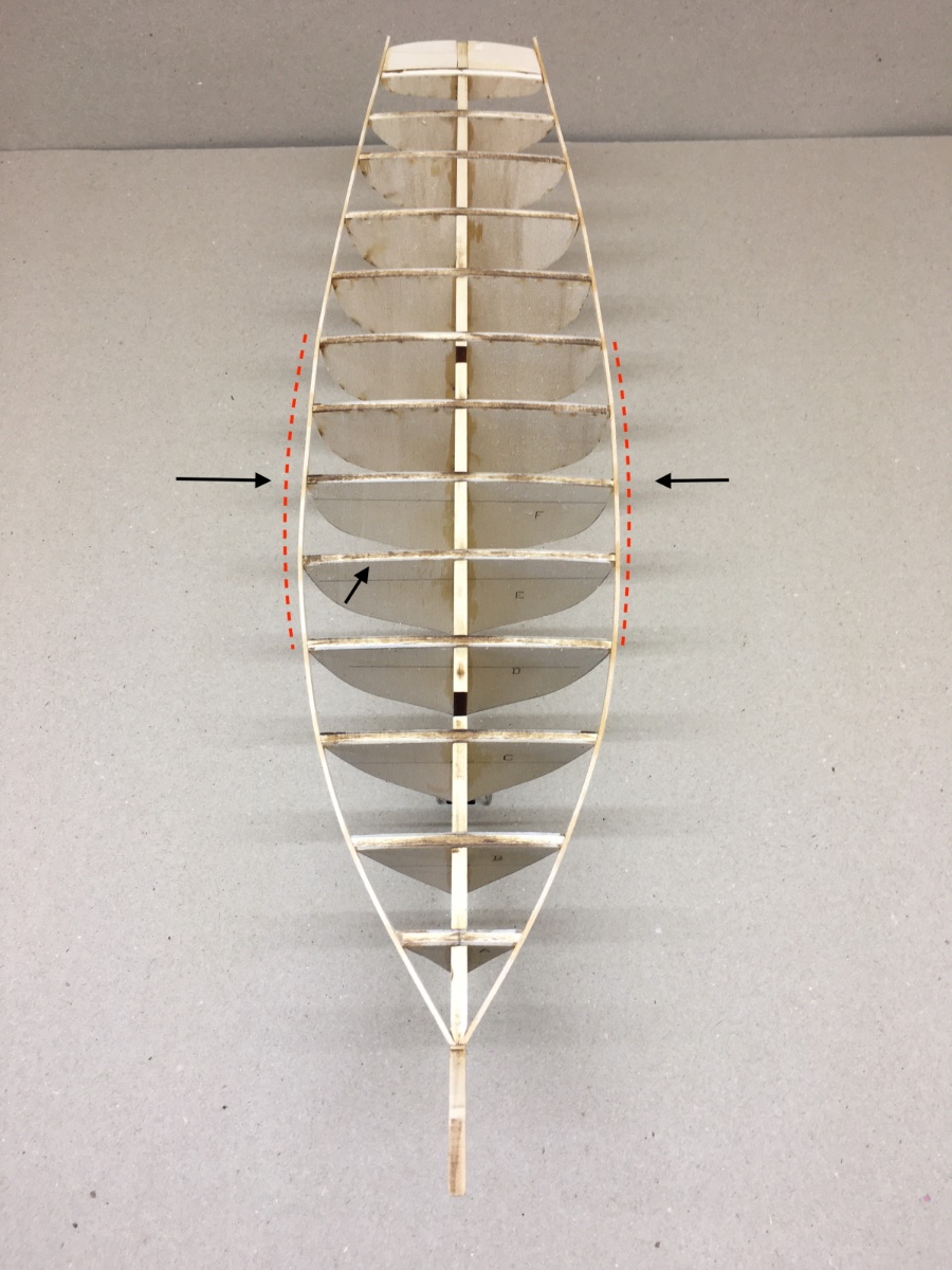
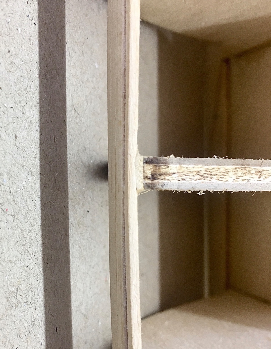
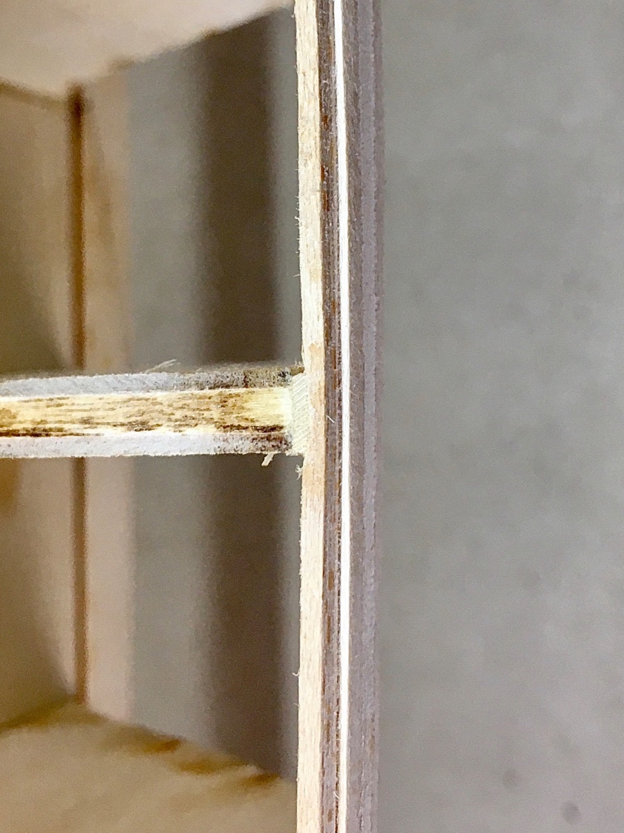
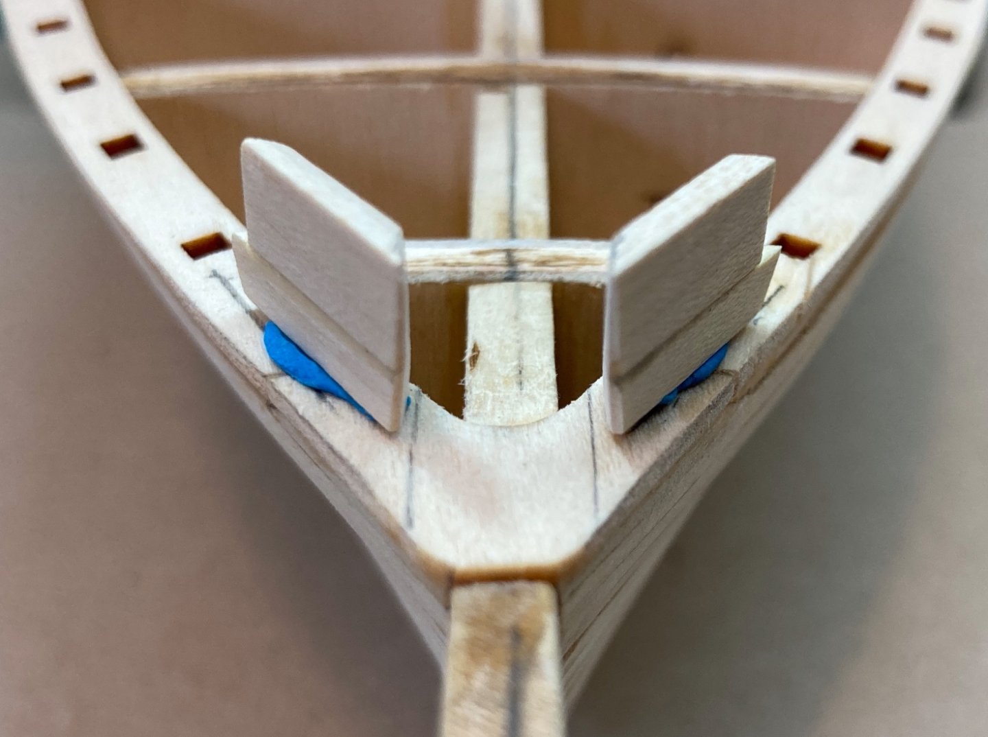
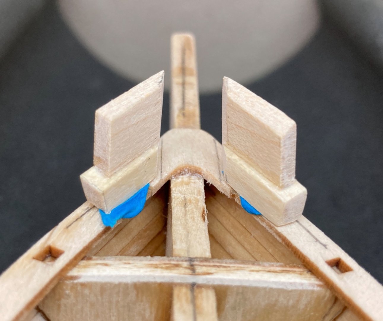
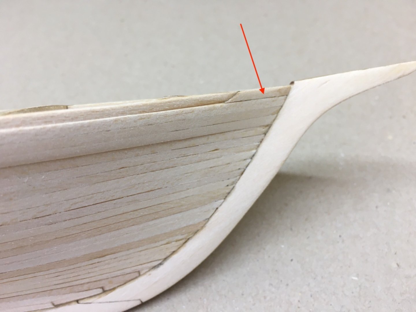
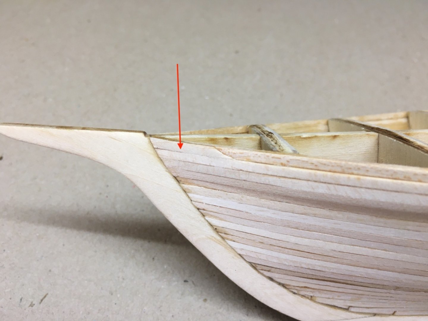
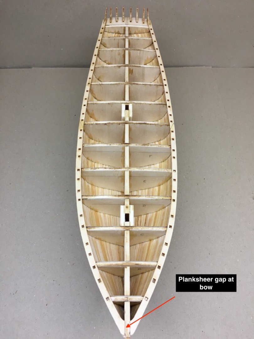
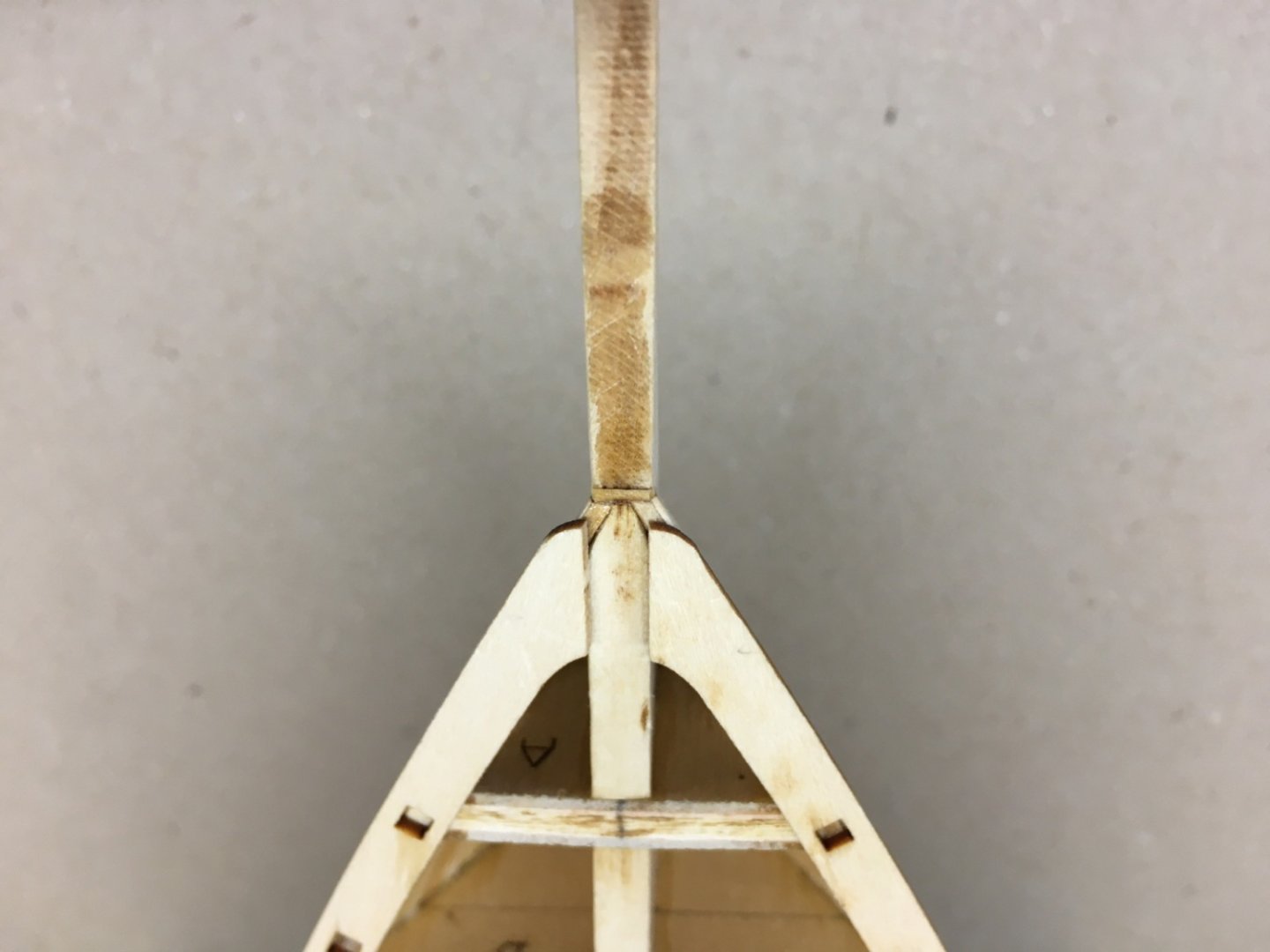
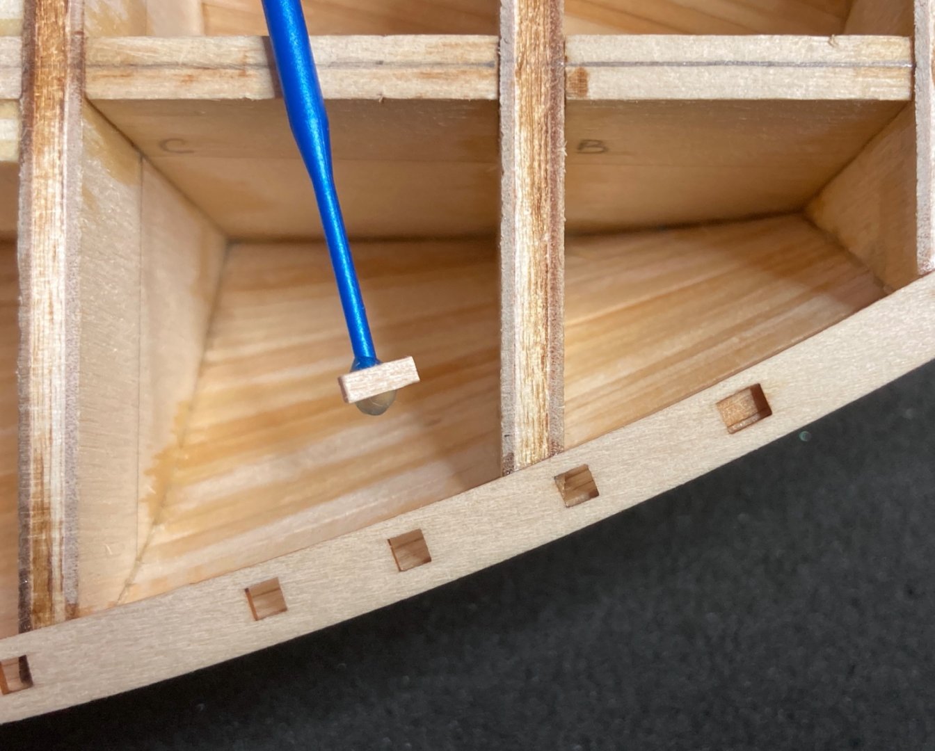
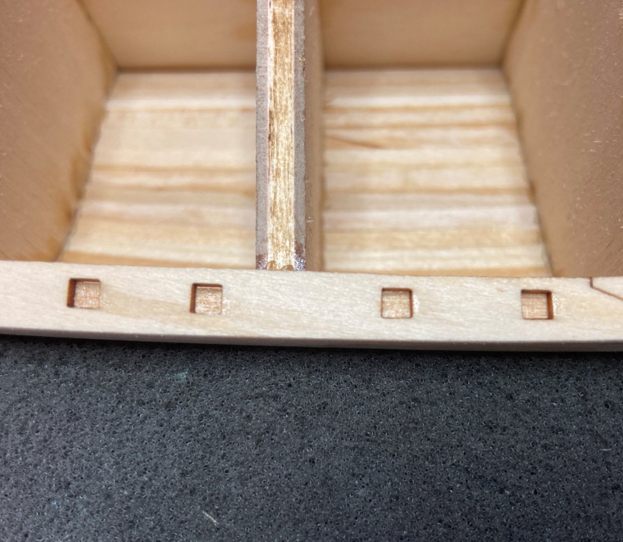
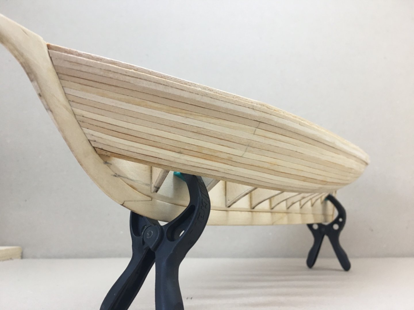
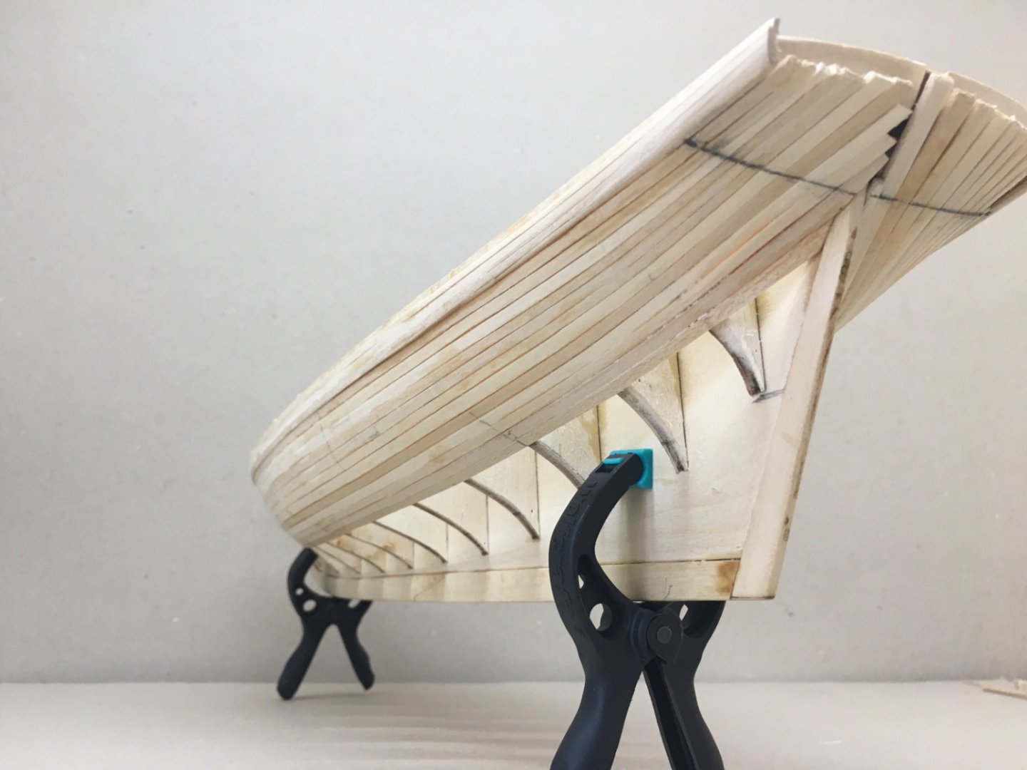
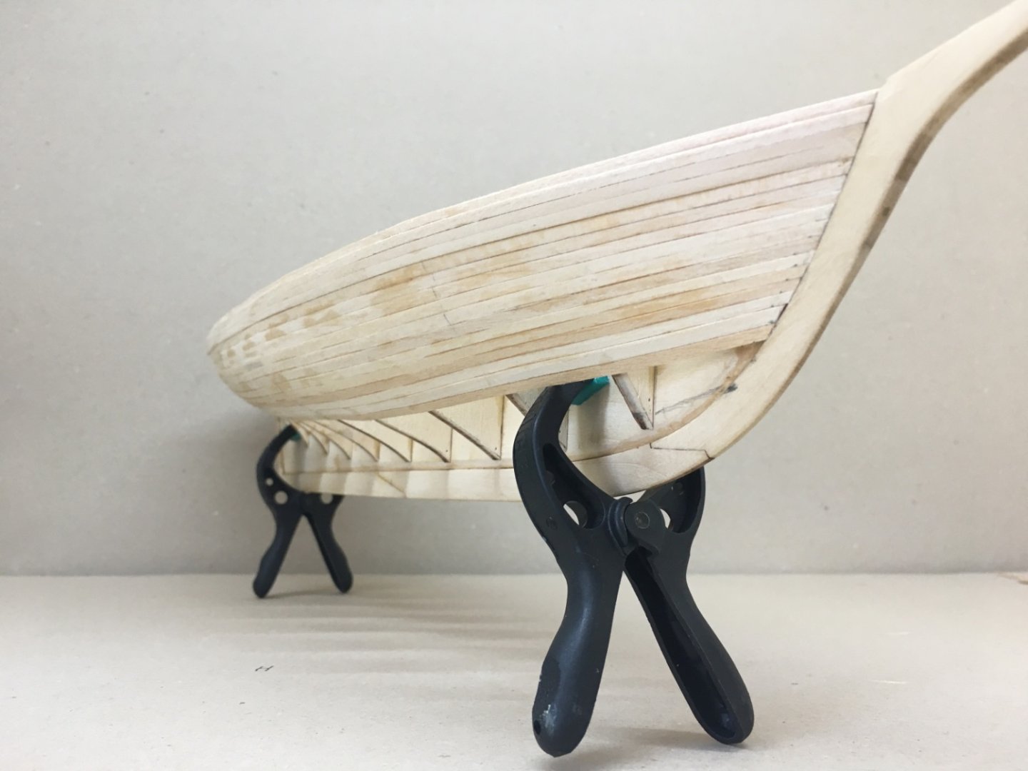
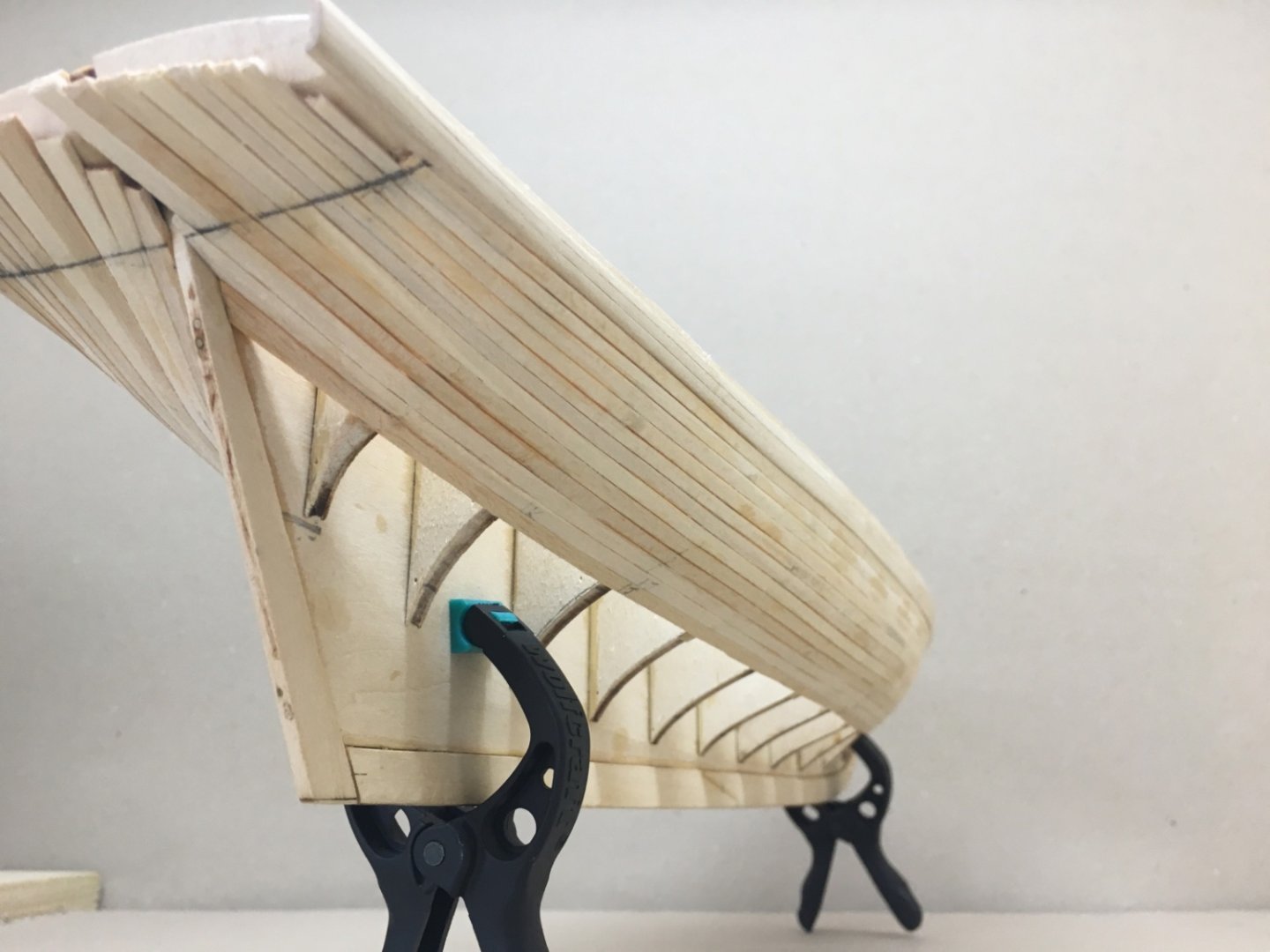
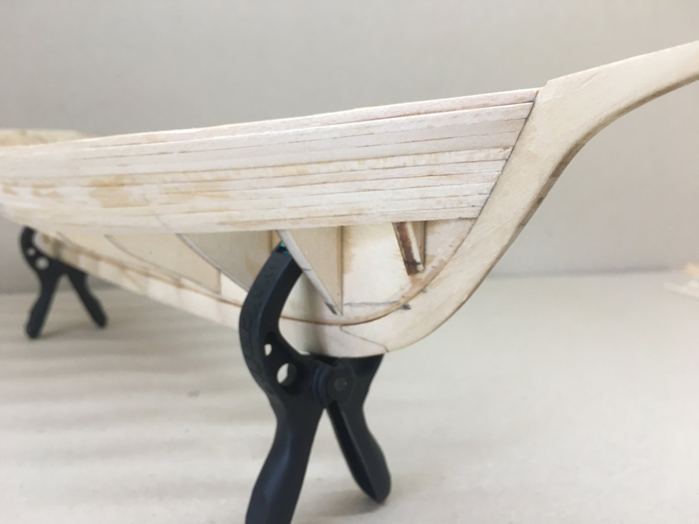
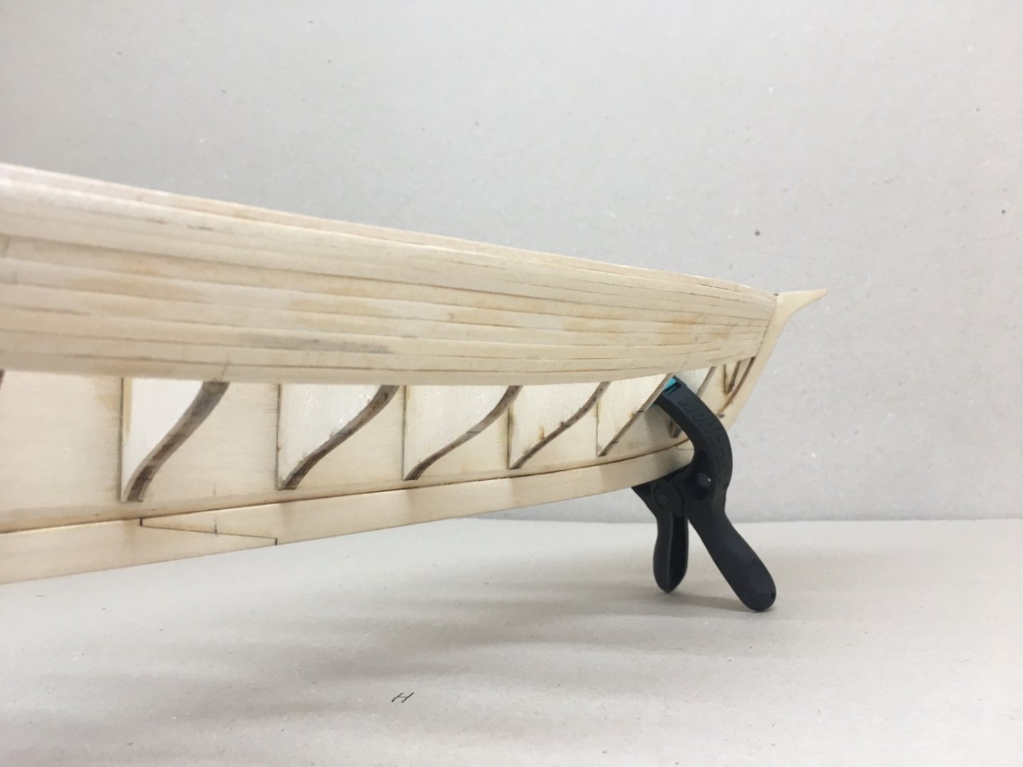
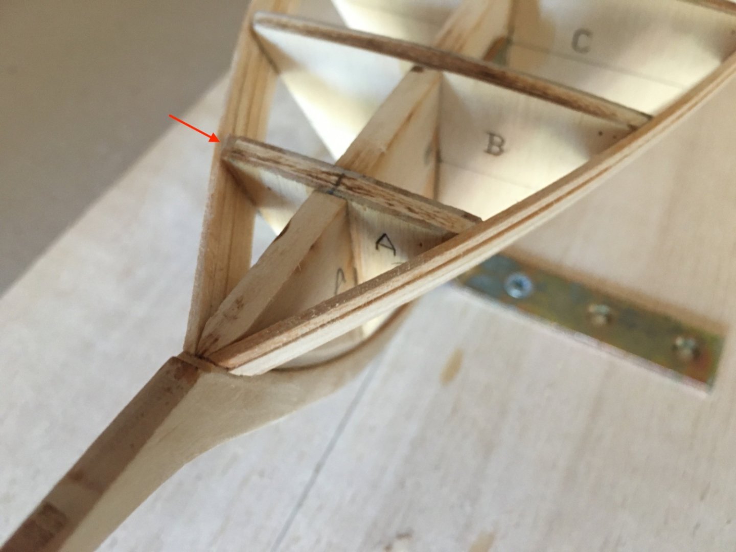
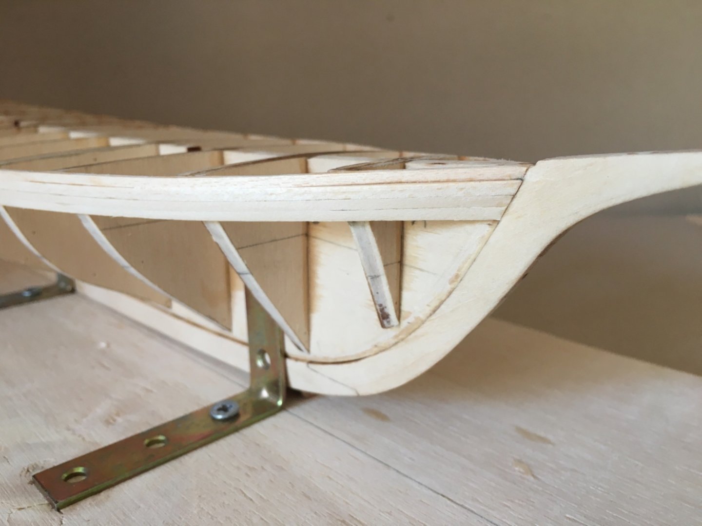
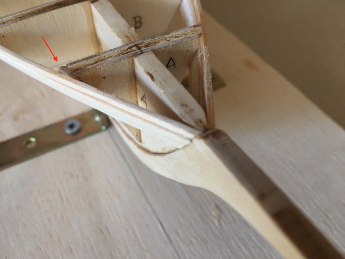
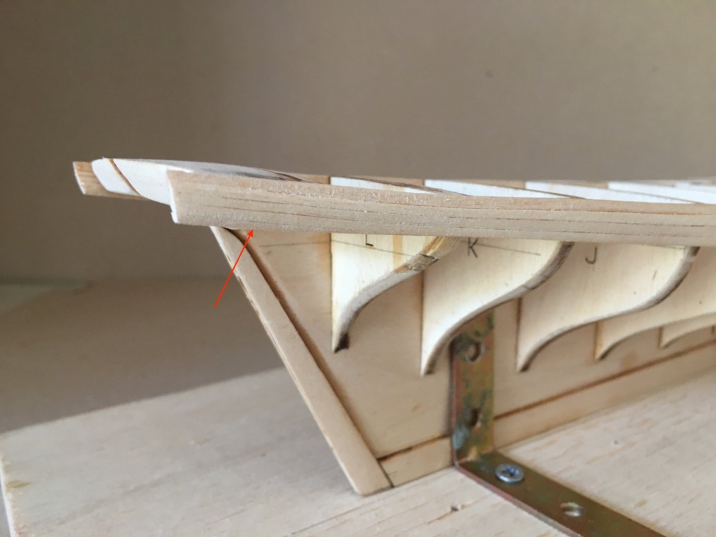
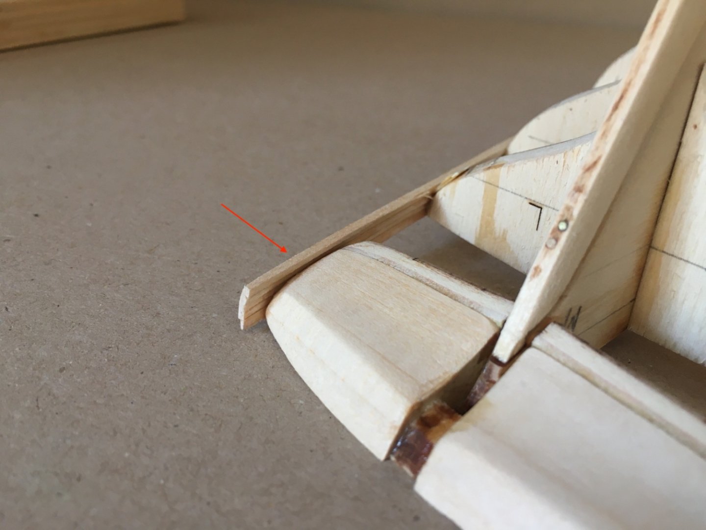
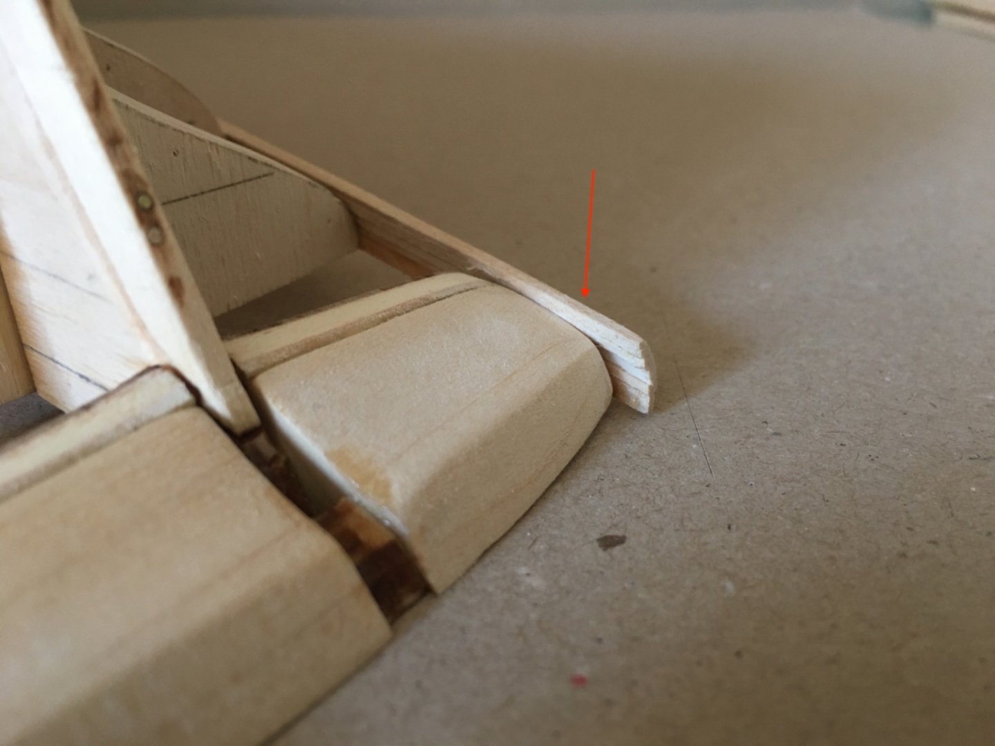
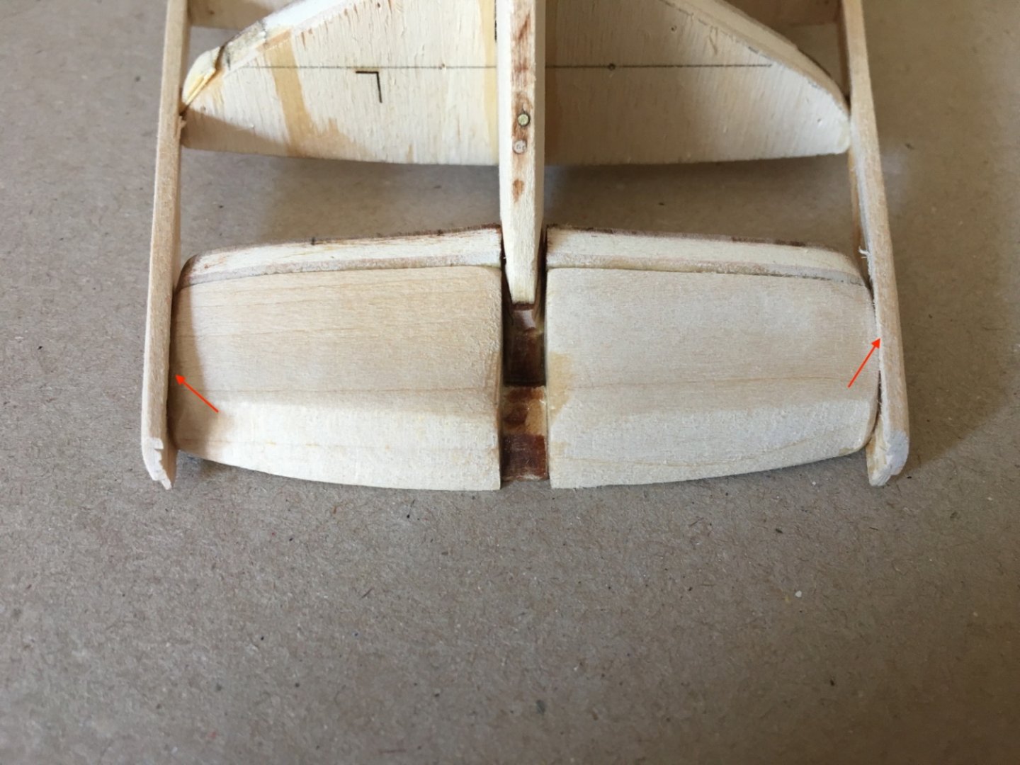
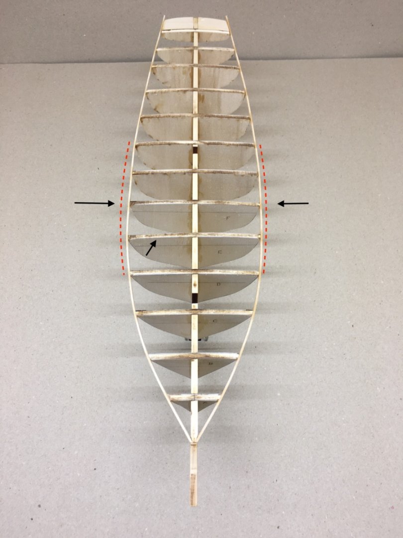
The next step is the beveling of the installed bulkheads and counter filler blocks. I used several grit sandpapers (ranging from 120 to 400) glued to wood blocks. Soft based or plain sandpapers are avoided at this step in order to prevent curved areas on bulkhead surfaces where hull planks are to be glued. In the picture below mainly numbers 3, which are wood based, are used. ( Please note that this picture relates also to the sanding of the hull after planking is finished. 1 : Manufactured PVC foam based 2: Commercial sanding blocks 3 : Manufactured wood based blocks 4 : Commercial sanding sticks 5: Sanding sponges . You can always modify the size, width or length in numbers 1, 3 and 5 suiting to your needs for different areas) During the sanding process I frequently used a planking wood strip to check the beveling level on at least neighboring 3-4 bulkheads. Beveling is critical in bulkheads K and L as the planking strip takes a sharp turn there. Also beveling in bulkheads E, F and G are minimal. Here are some pictures taken after beveling process from various angles. Please note that on some bulkheads the reference lines for beveling are still intact. Had I have done the beveling before the bulkheads are installed and only taking the lines in consideration , there would be a lot of problems to be corrected. I understand that the transfer of the beveling reference lines from plans to bulkheads was not 100 % exact , but nevertheless I believe to bevel the bulkheads after their final installment to keel is the proper and safe way. The next step is hull planking and it starts with the installment of the first plank. The first plank is 1/16 by 3/32 inches ( 1.6 x 2.4 mm ) and it is ready in the kit stock. It is straightforward and needs no tapering. However here you have a choice to make. Install the first plank and carry on with rest of hull planking or install the planksheer on both sides of the deck first and then start with the first plank and carry on. The planksheer must overlap the bulkhead by 3/32 inches (2.4 mm ) which leaves an overlap of 1/32 inches (0.8 mm) after the installment of 1/16 inch (1.6 mm ) thick first plank. I thought it is easy to accomplish this 1/32 inch (0.8 mm) overlap by positioning the sheerplank on the first hull plank later. So I started with the first hull plank. Before the pictures , a few words on how I did the gluing process when planking the hull. I used gel (late action like 20-30 seconds) and liquid (prompt action 5-10 second) CA glues when I do planking. I always apply the glue , whether gel or liquid, with an applicator I made my self. It is simply cutting the thread passing holes of various sized sawing needles and leaving a fork shaped end and then inserting them to the holes opened on dowel ends. Below is two pictures from a previous project (Maine Lobster Boat) to give you an idea. I applied gel CA to the points on bulkheads where the planks is to be placed. I started from the bow. It was easy for me to shape fore end of the plank to fit the rabbet grove at the bow and align with stem. I moved back to stern direction , applying gel glue to 3-4 bulkheads at a time and holding the plank for at least 20-30 seconds. Then I applied liquid CA glue with the applicator to the contact points. I think using CA glue at this hull planking step have two advantages. First the planking process is quick and foremost it is easy to correct mistakes by using CA glue debonder and free the connection area as you will see examples later. Now here are the pictures of the first plank installed. In the next two pictures you can see a critical area at the bow. Pointed with a red arrow you can easily see the level difference between stem and keel. This difference is important as the fore part of planksheer will be placed here and its level will be a bit higher than the stem this time . This level difference will later create the little space between the bowsprit and stem which is indeed present in the original ship. Then comes the next 3 planks which are actually one piece in the original ship and they are called ' the Wale'. They are different from the first plank in size ; 3/32x3/32 inches ( 2.4x2.4 mm) and ready in the kit stock. They are tapered towards the stern to 1/32 inches (0.8 mm). An important point here was to bevel the top of the second plank according to the bottom of the first plank and so on. Now starts the gluing of the planks to the upper ones between bulkheads. I used liquid CD with applicator for this purpose. I installed the planks 2 , 3 and 4 in this manner and working alternatively between starboard and port sides. Here are some pictures. The red arrow shows the shims applied to bulkhead A , which resulted from beveling the bulkhead before installment. Planks 1, 2, 3 and 4 are the only ones reaching to the aft end of the counter and transom. All the others will end at the aft end of bulkhead M or at sternpost. After the hull planking is finished , counter must be planked also by planks perpendicular to keel this time. In order to achieve a flush neighboring of the wales and counter planks, small pieces of wood strips (Indicated with red arrows ) are added to both sides at this counter area , tapering to zero at bulkheads L and K. No matter how careful and precise you think you are, there will always be small mistakes which you won't notice as you will be biased and used to how the model in front of you on the worktable gives you a picture. Here comes the advantage of other eyes. As I am a member of a local scale modelers forum and was posting a blog of POB II building process, modeler friends quickly spotted a mistake. As you can see in the picture below, shimming is necessary in bulkheads F (starboard and port) and G (starboard). Bulkhead E is not properly squared also. These mistakes were corrected. Suitable size wood strips were added as shims . The connection areas for these shims are freed by using CA debonder. In order to correct the mistake on bulkhead E , the connections of the bulkhead on both sides to the first 4 planks were freed by CA debonder and the bulkhead was moved towards aft on starboard and fore on port sides just a little by checking with a suitable square wood block and glued again. Bulkhead F starboard side Bulkhead F port side Comparison of the before and after correction Next post will be the start of proper hull planking.


- 114 replies
-
- 5
-
-
- Pride of Baltimore II
- Model Shipways
- (and 1 more)
-
yvesvidal, Thanks a lot for your nice comment Halit
- 114 replies
-
- 1
-
-
- Pride of Baltimore II
- Model Shipways
- (and 1 more)
-
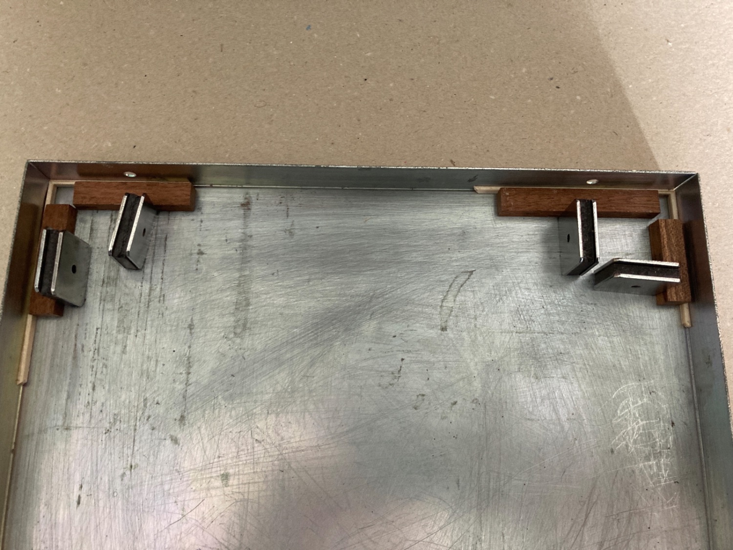
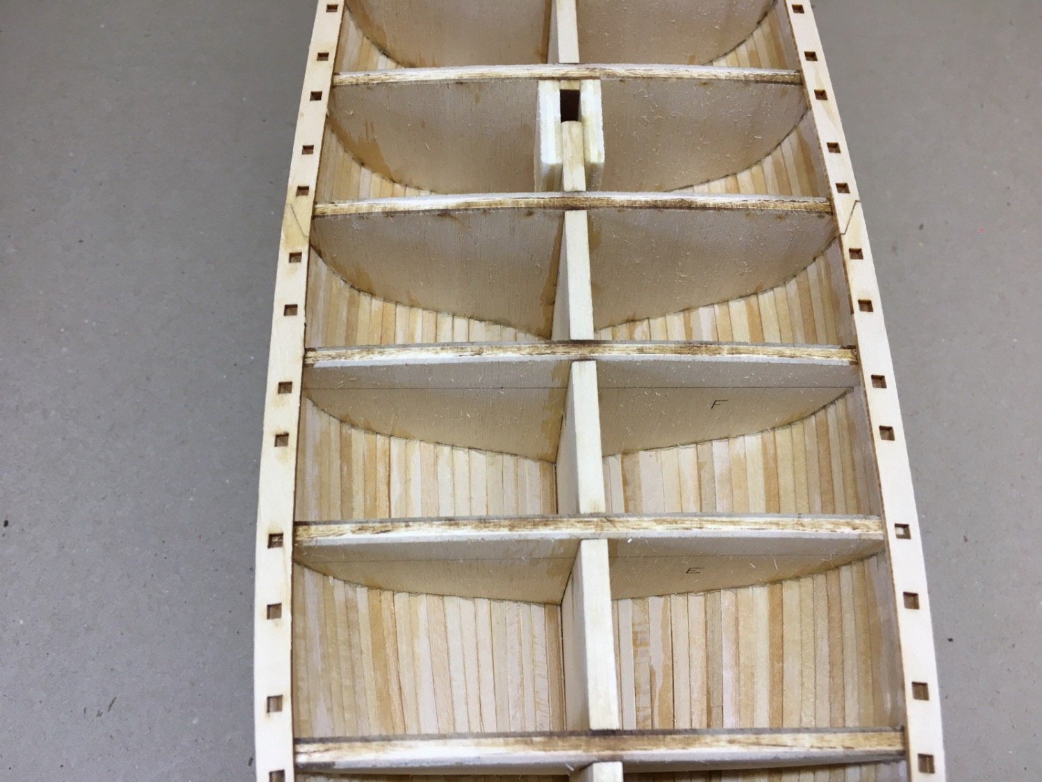
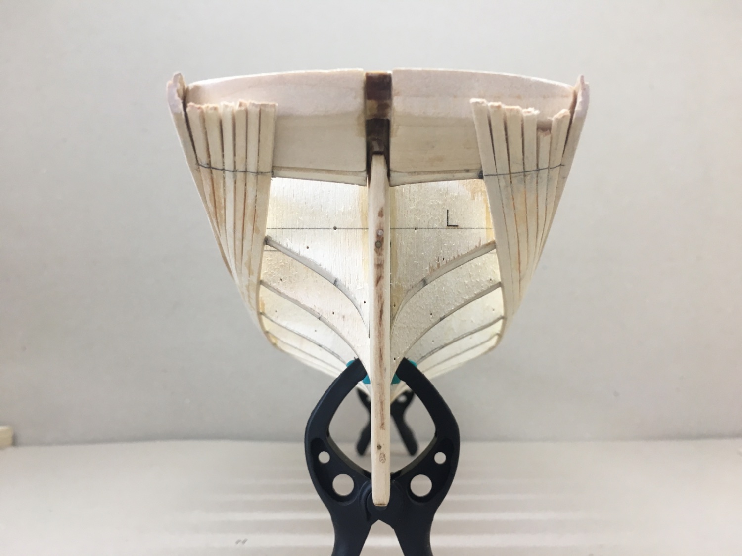
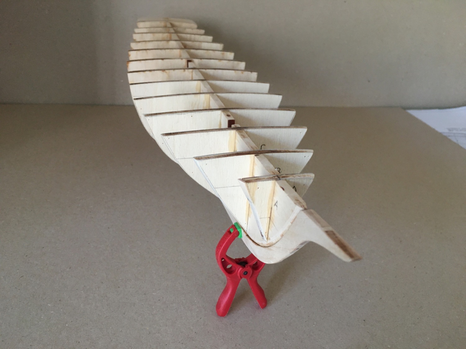
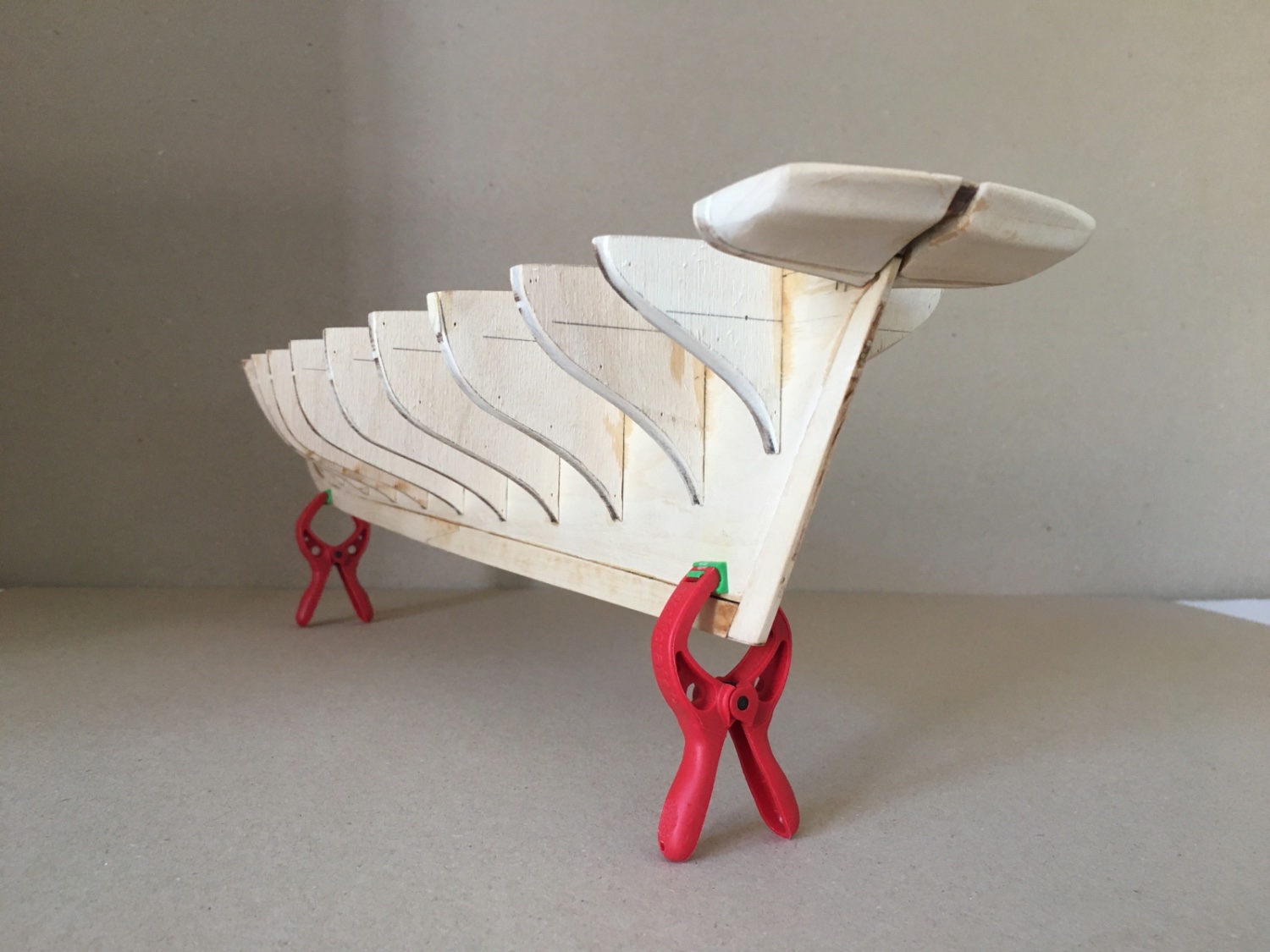
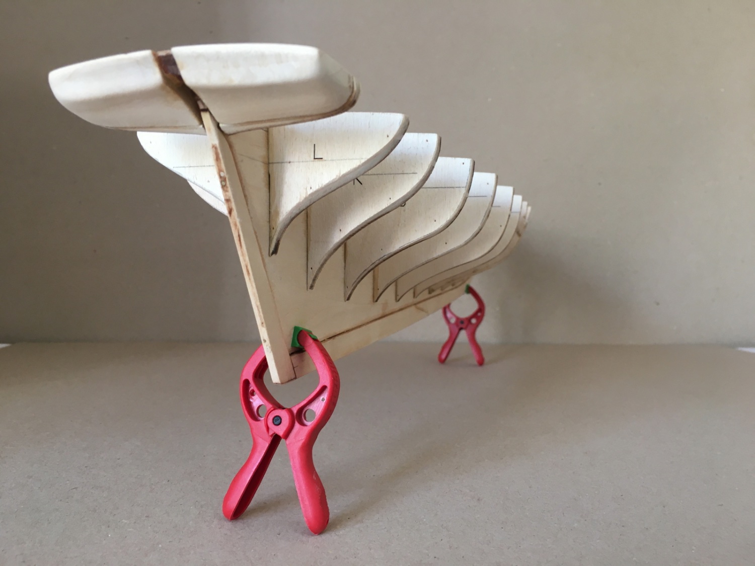
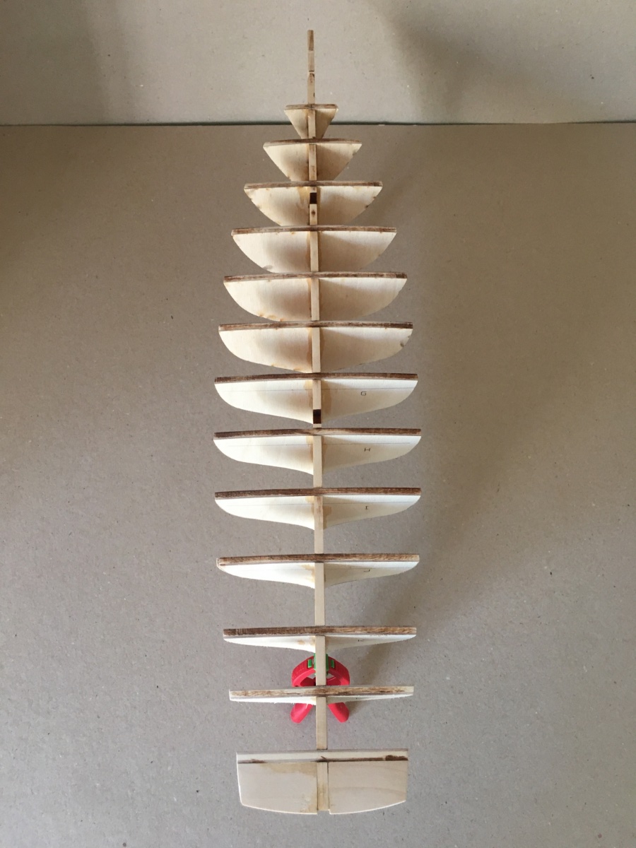
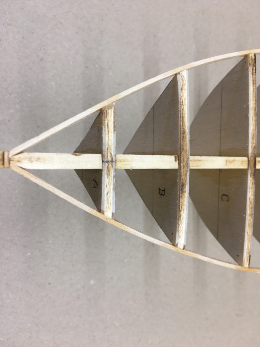
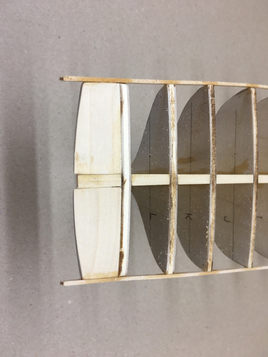
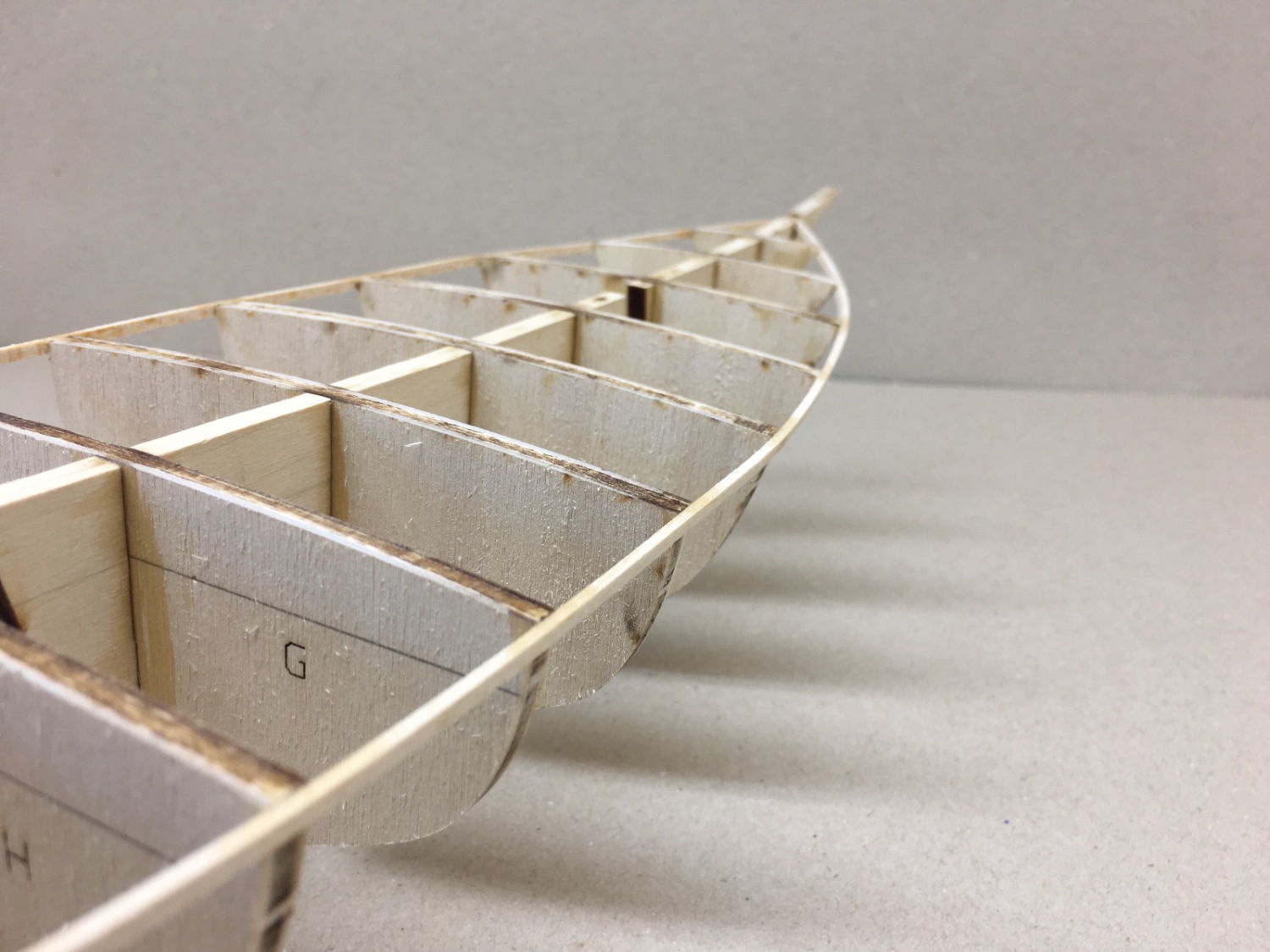
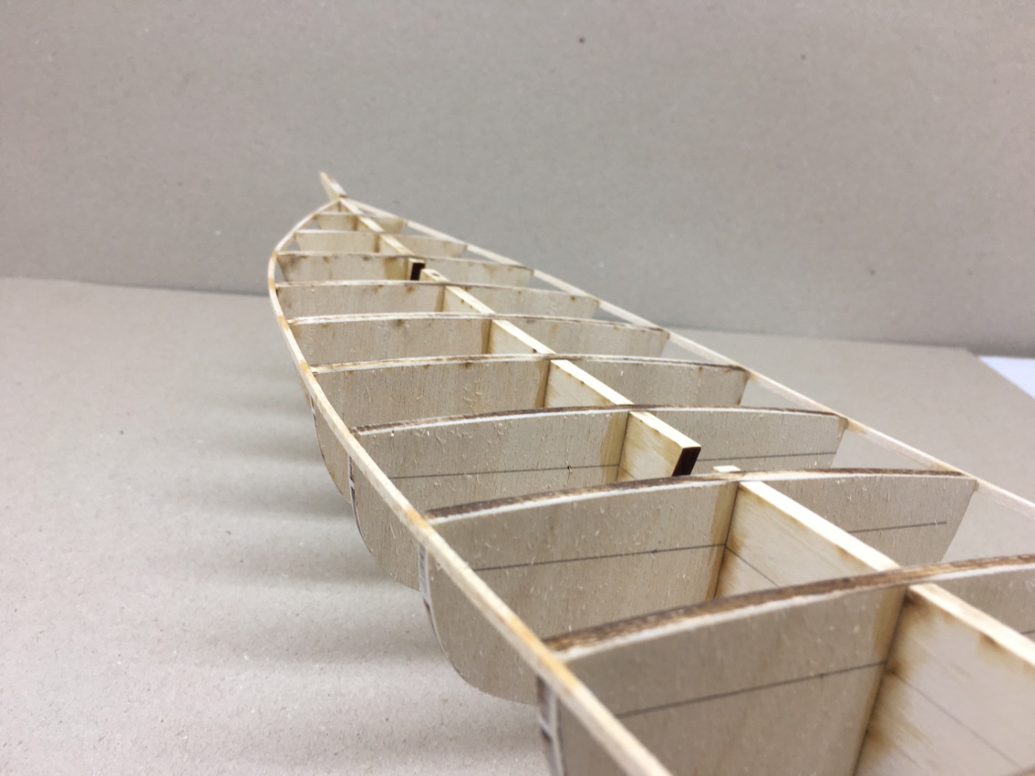
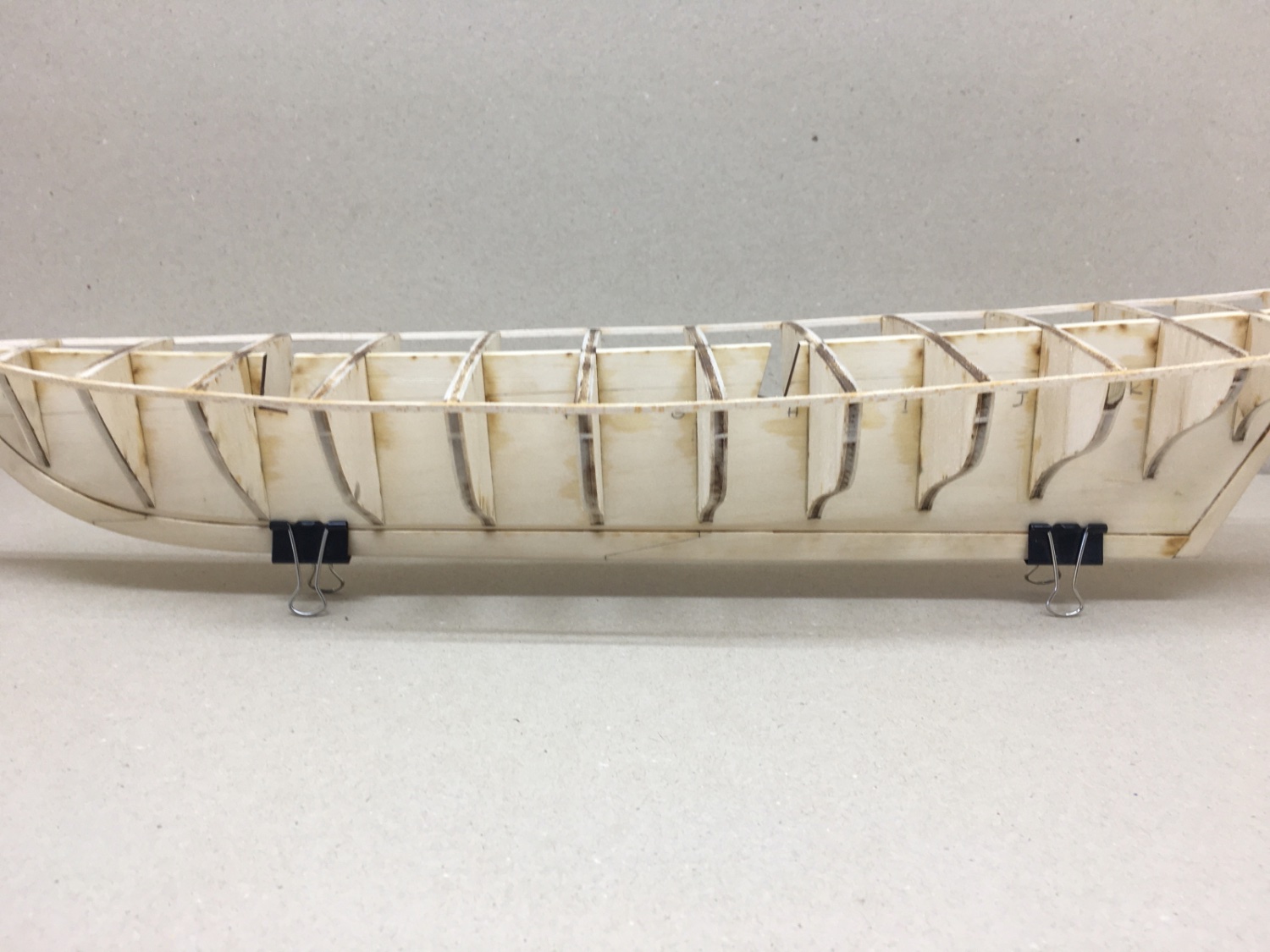
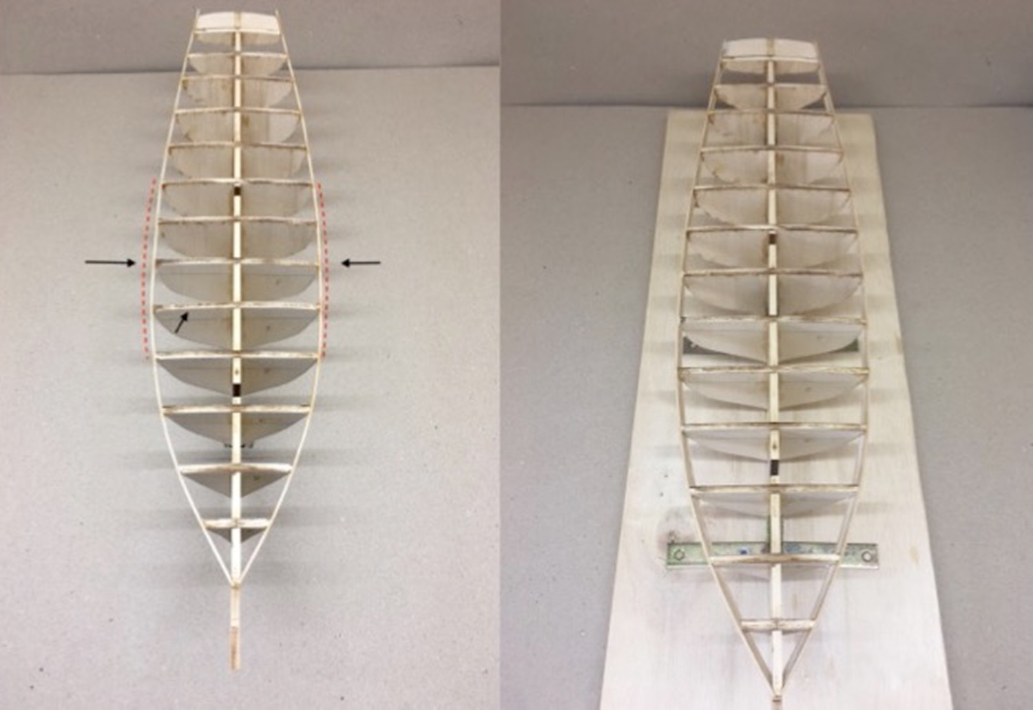
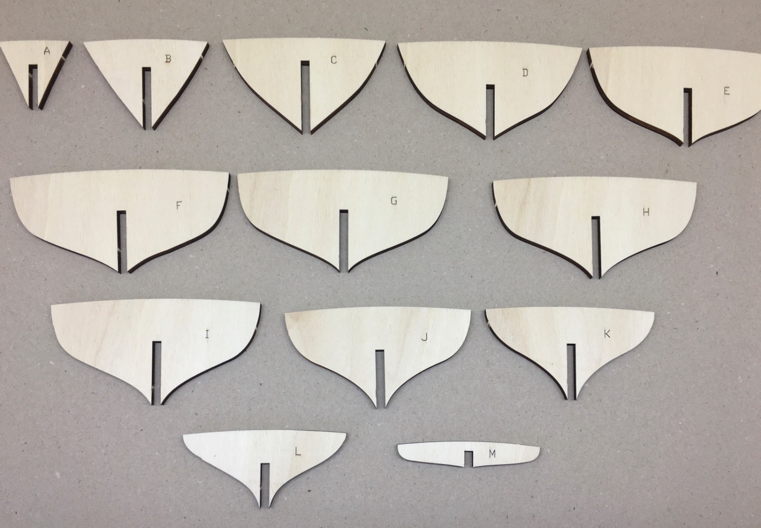
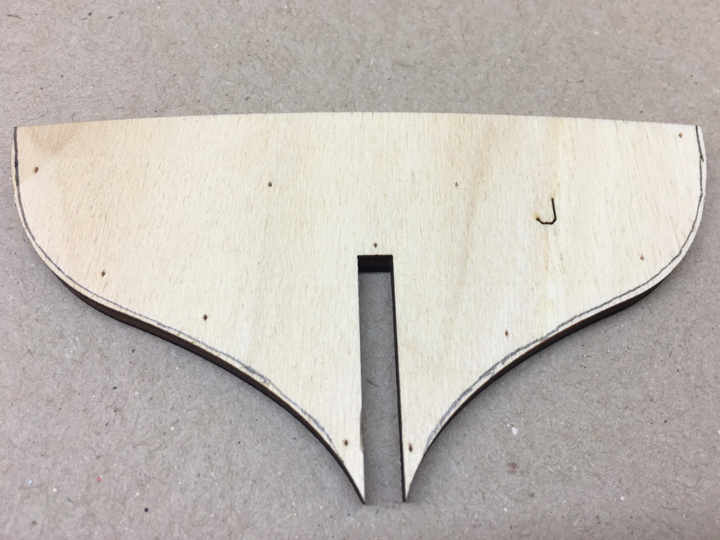
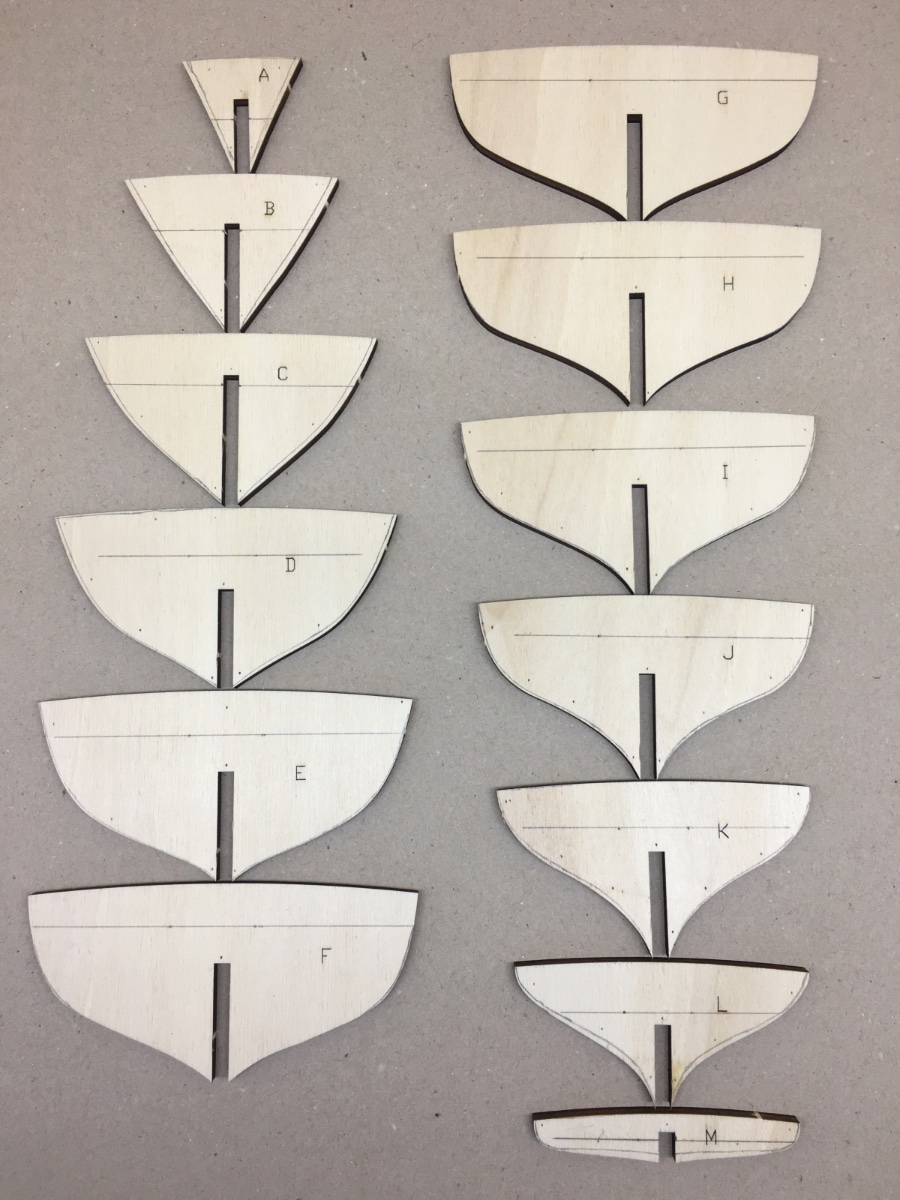
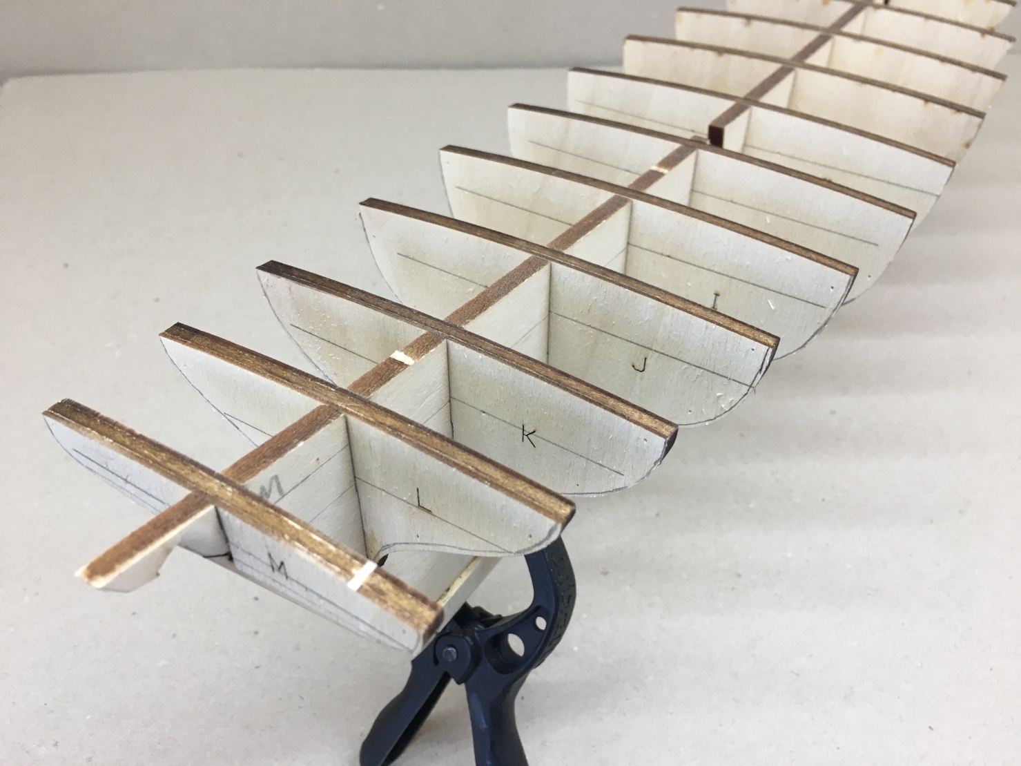
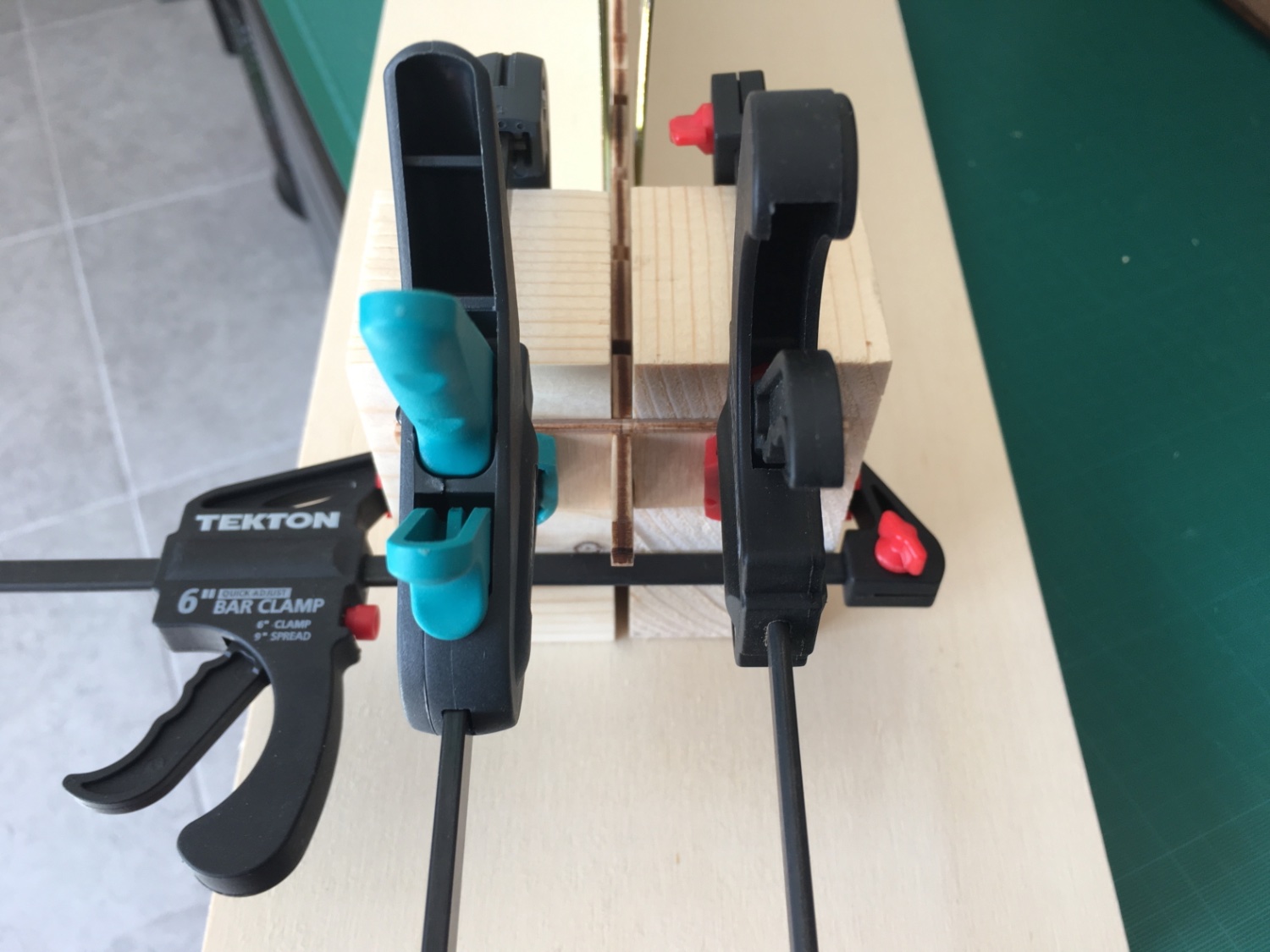
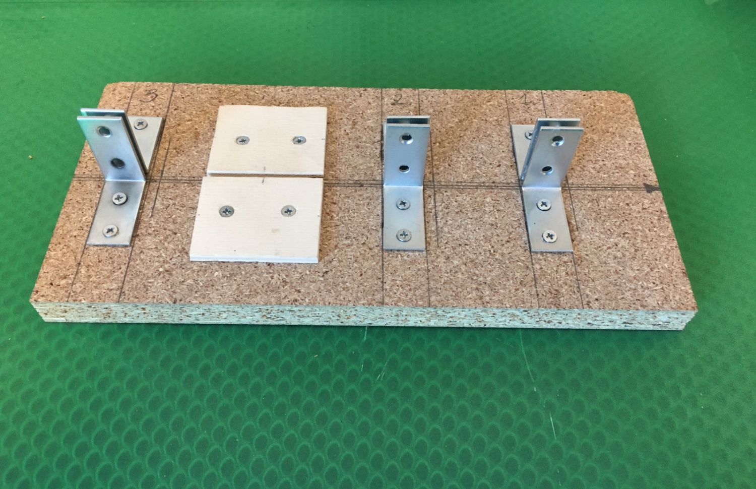
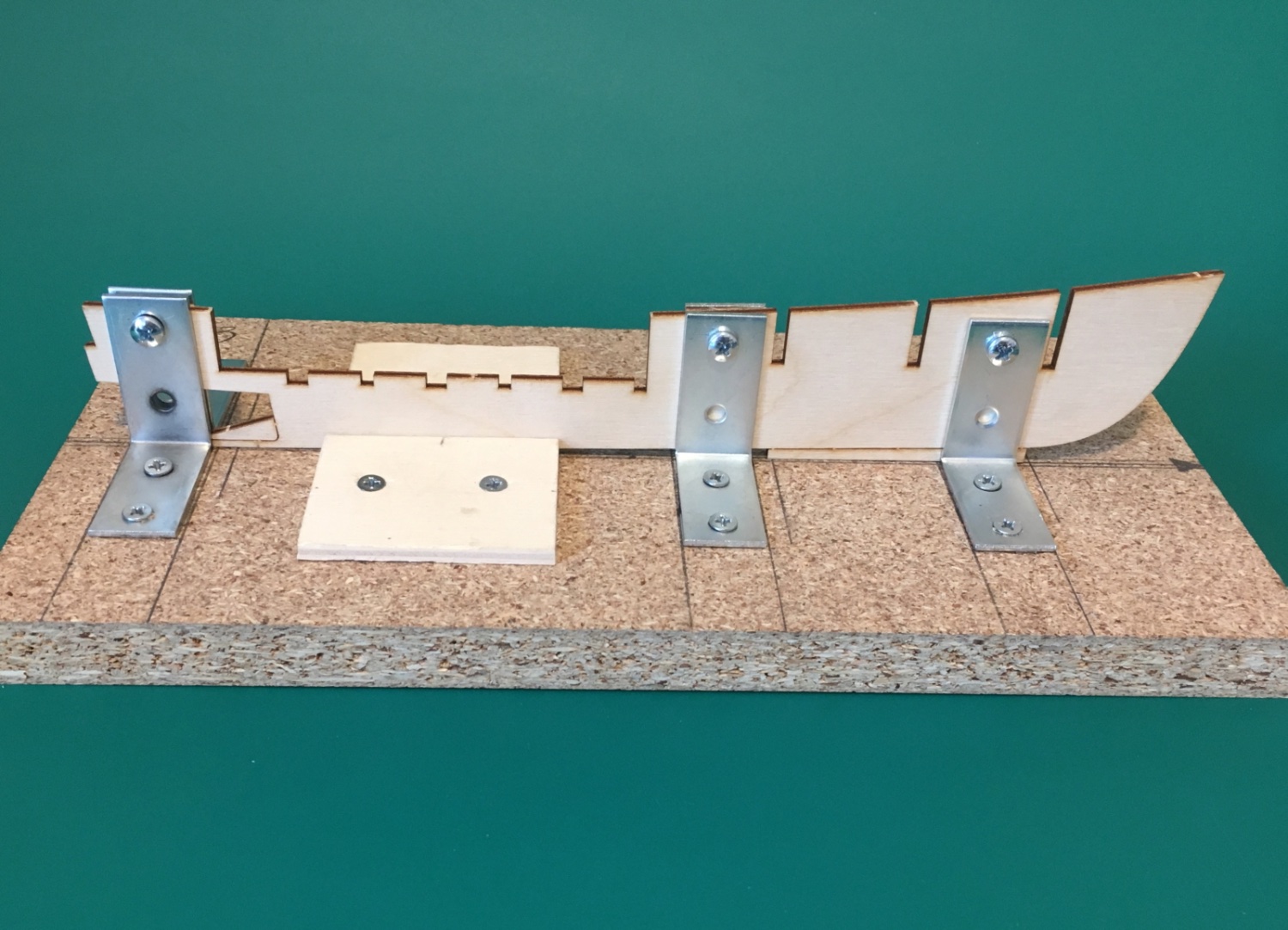
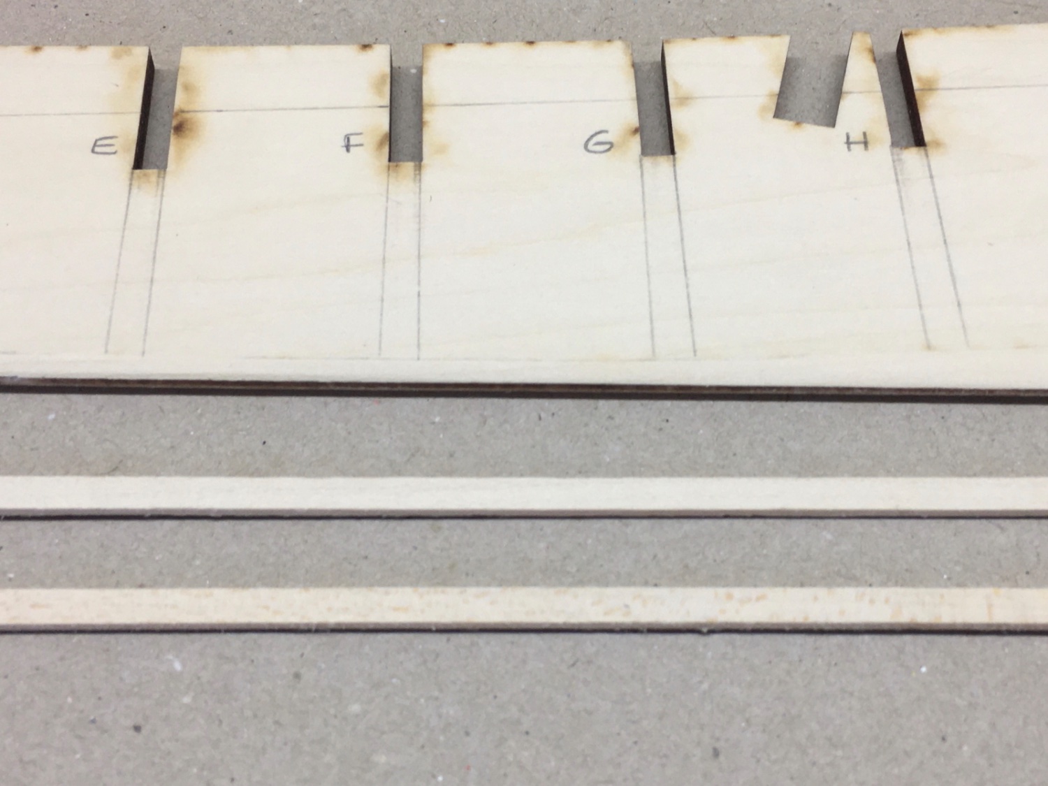
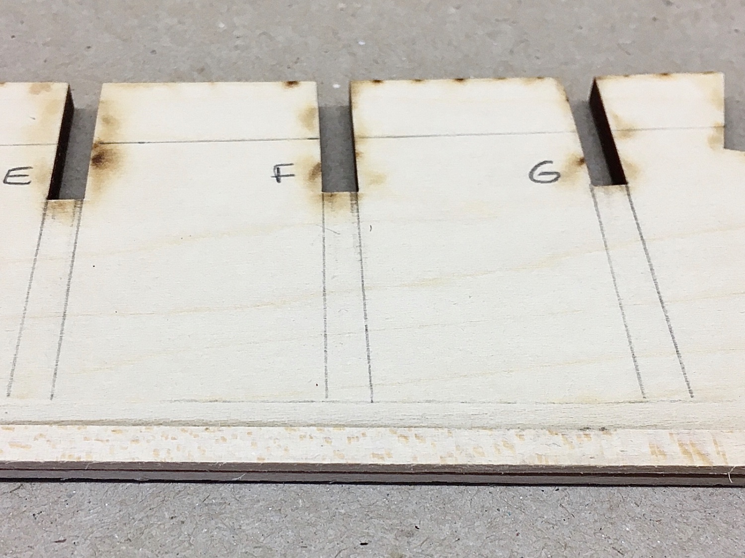
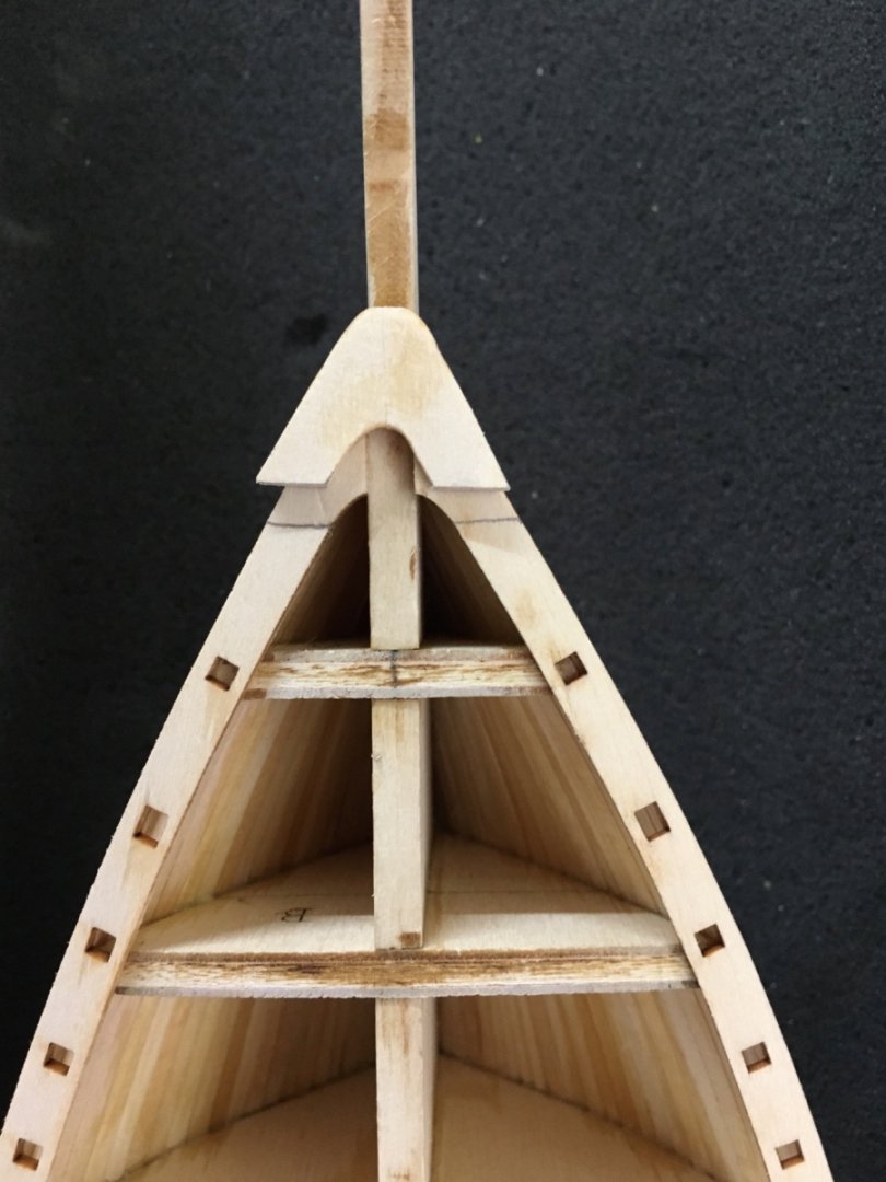
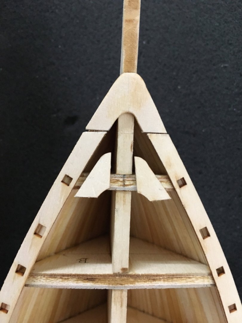
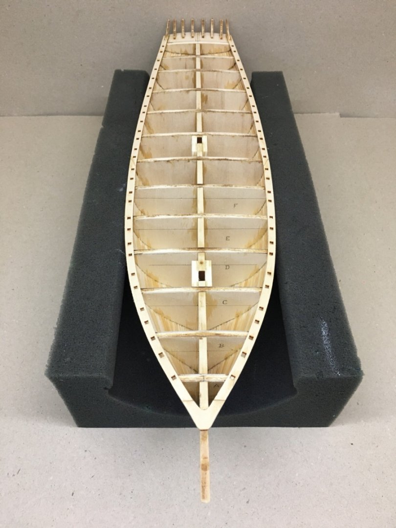
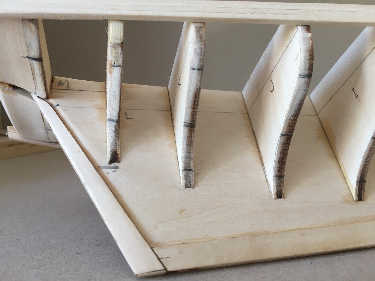
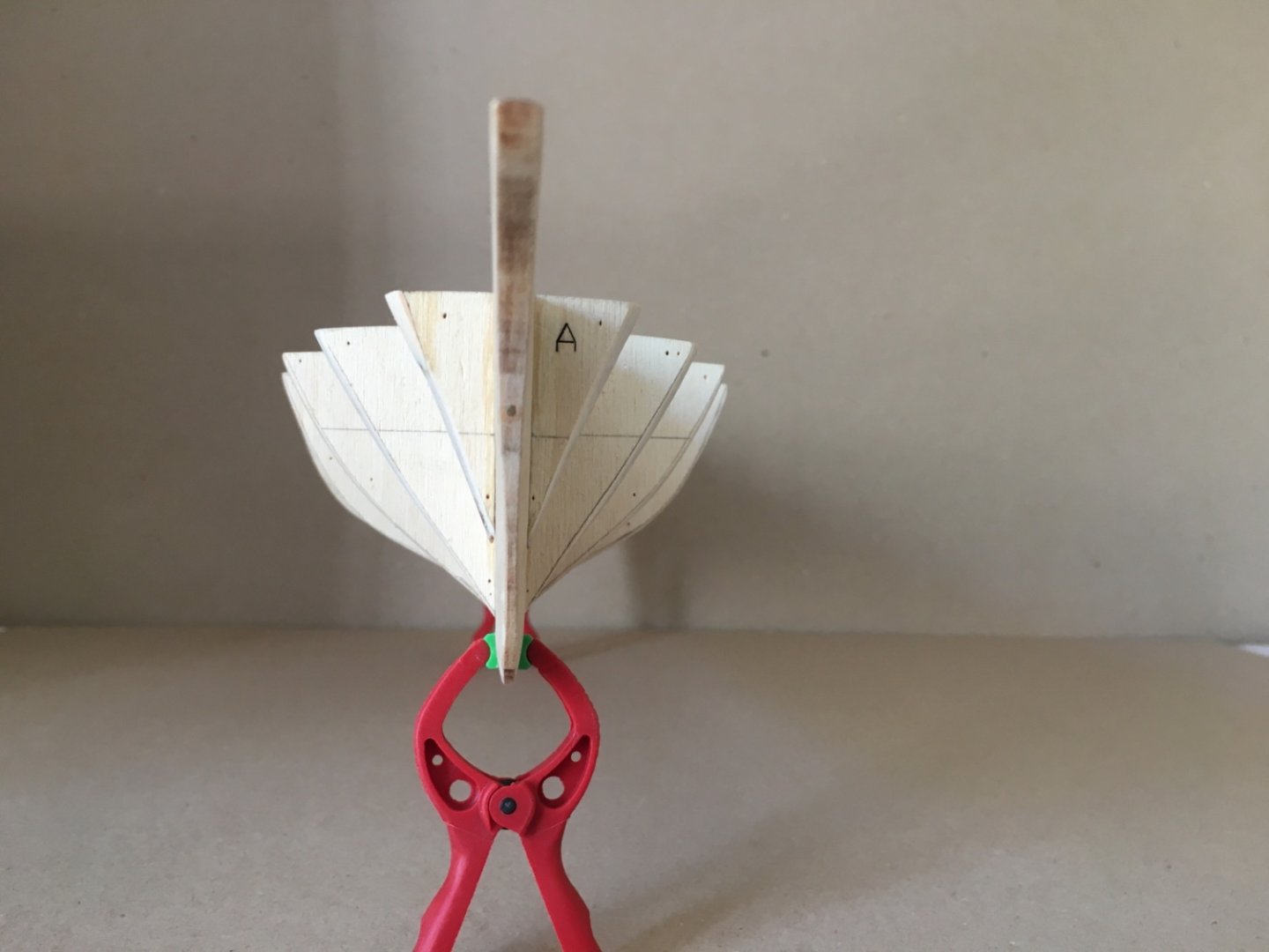
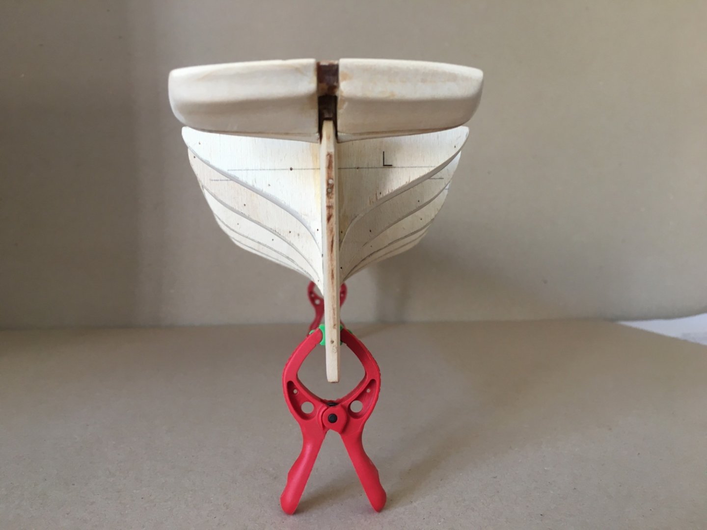
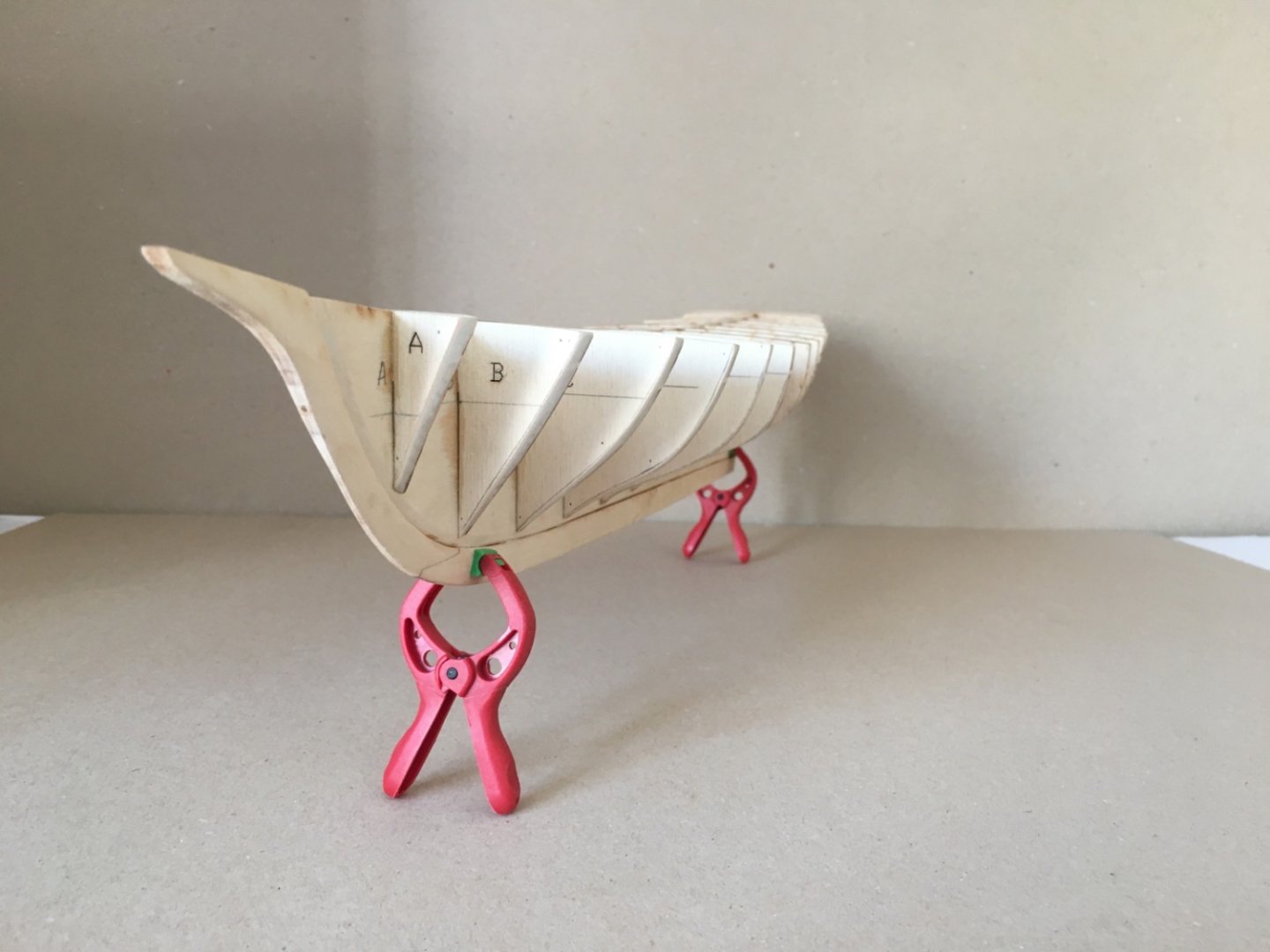
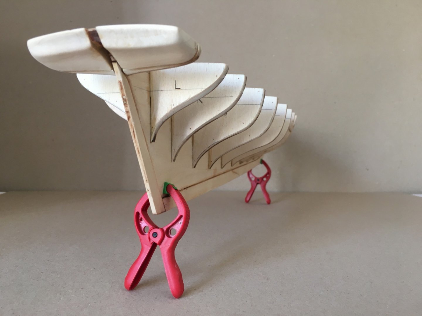
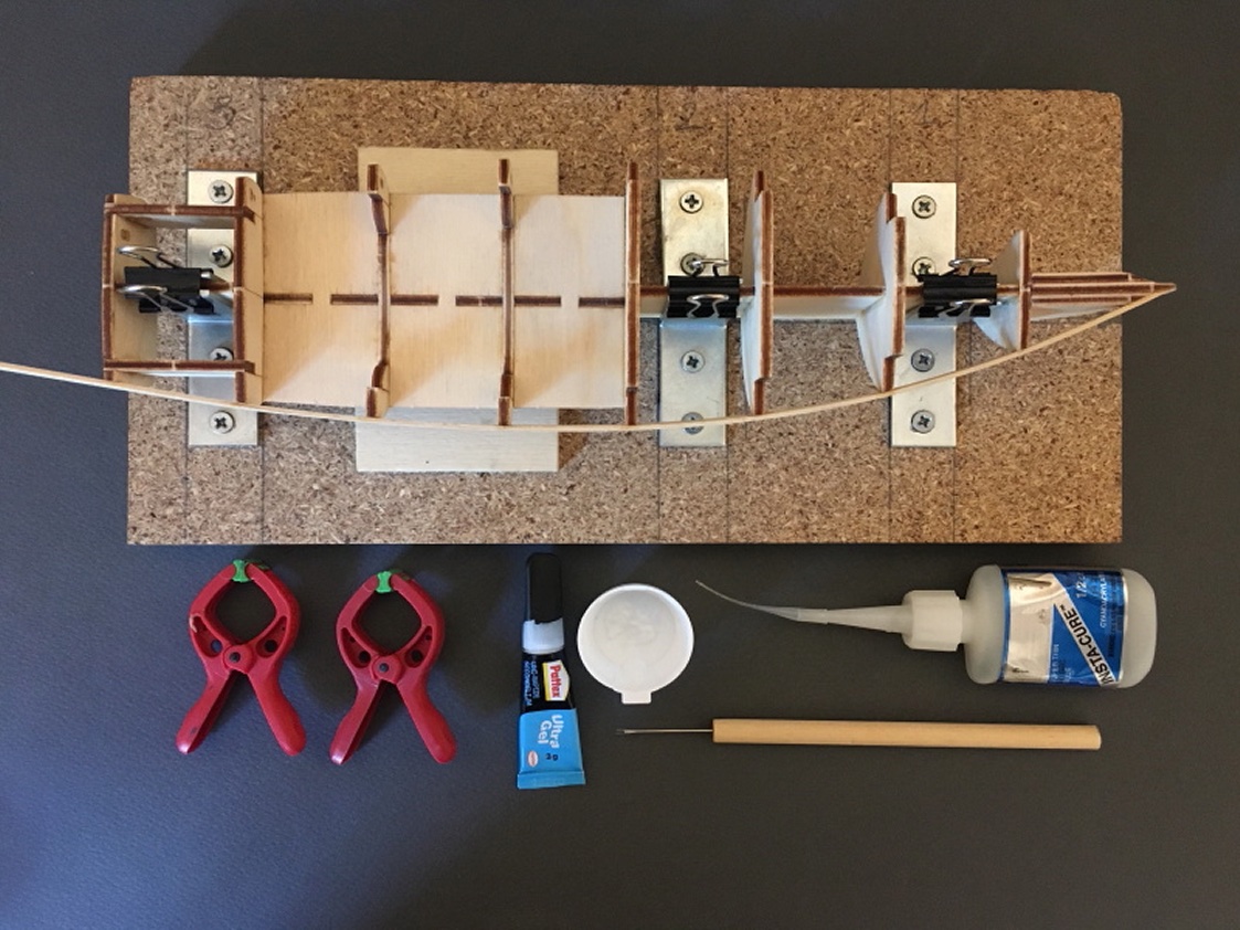
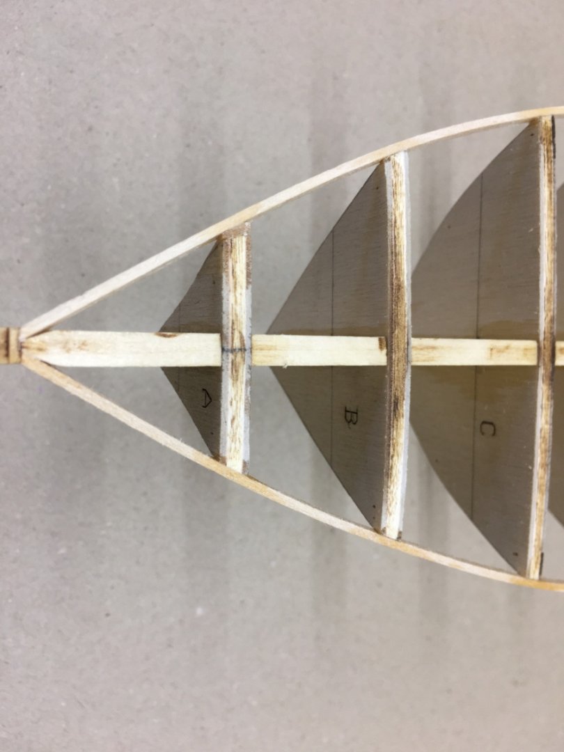
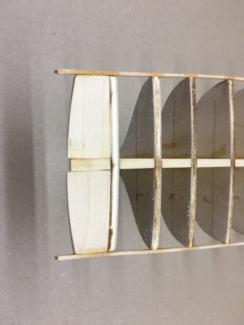
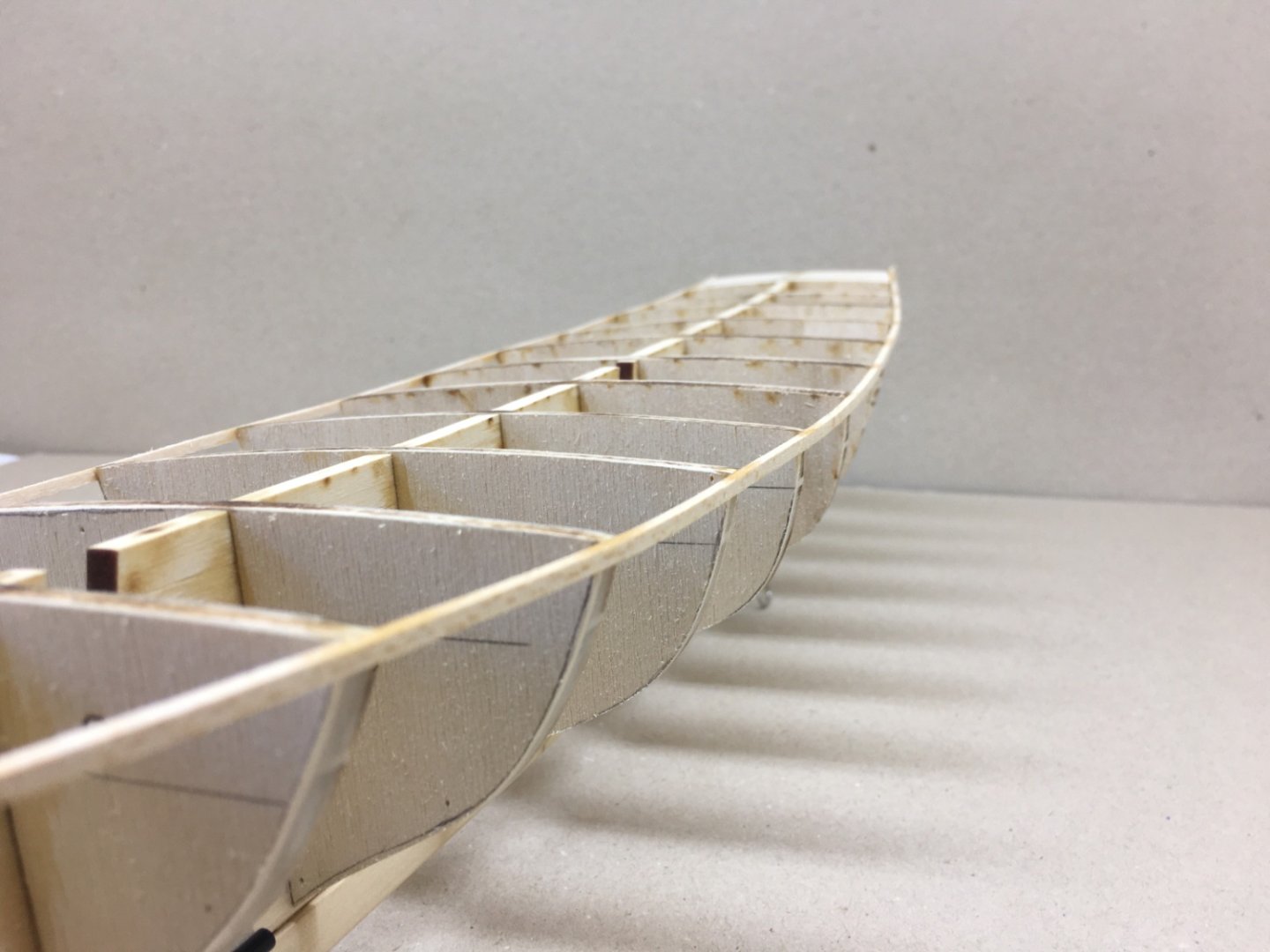
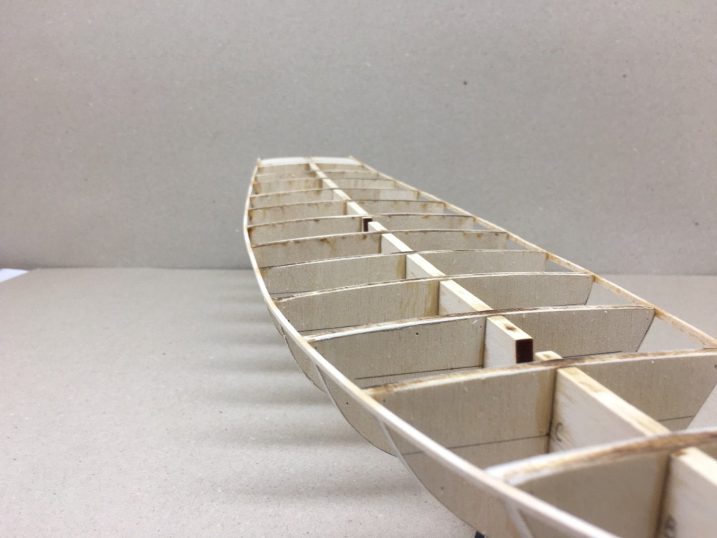
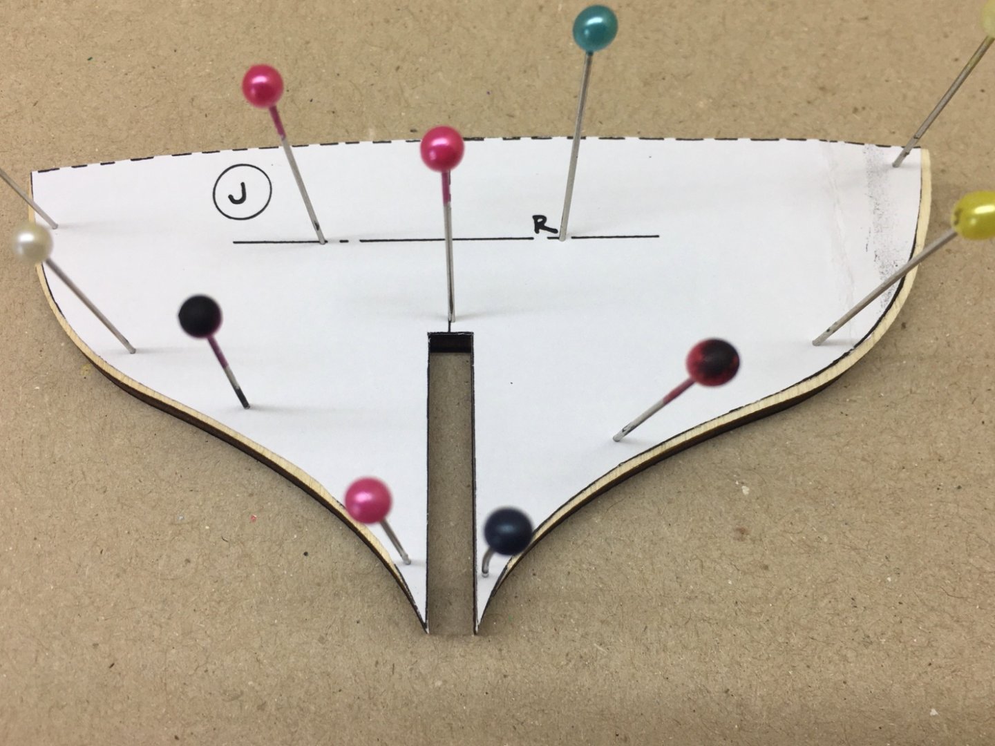
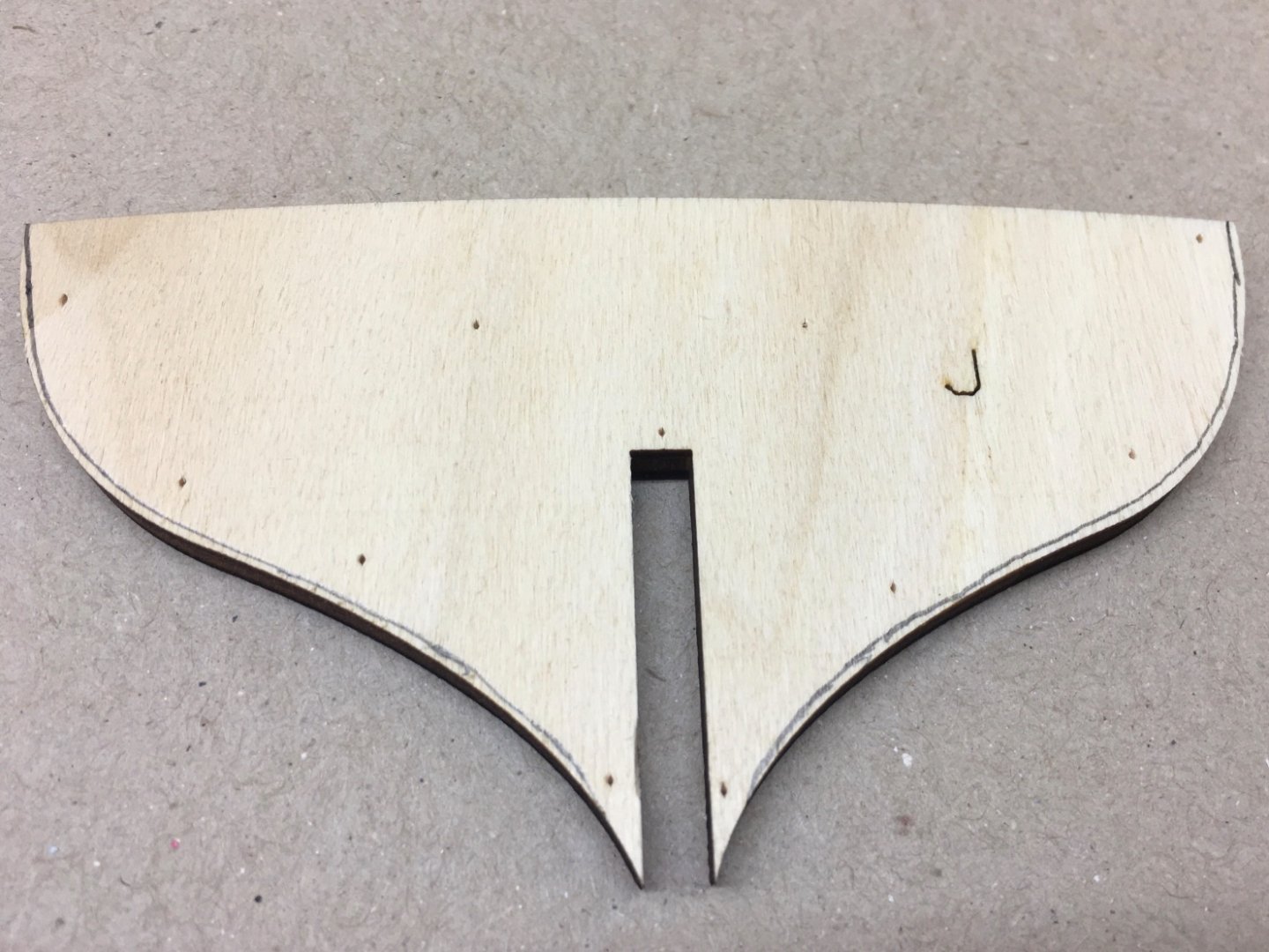
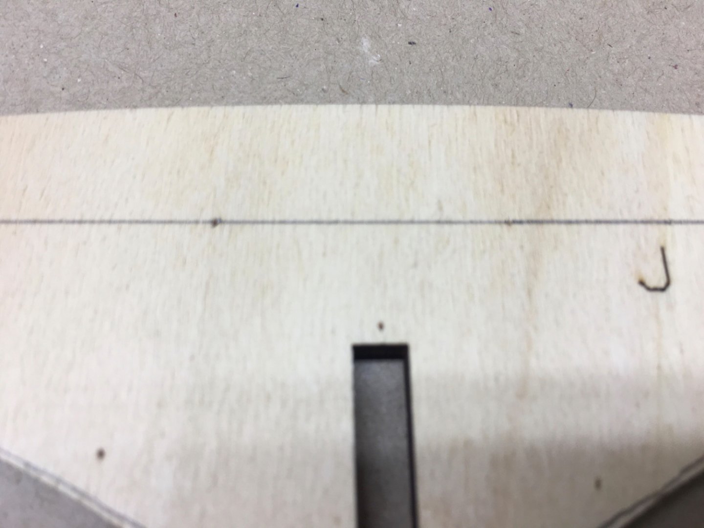
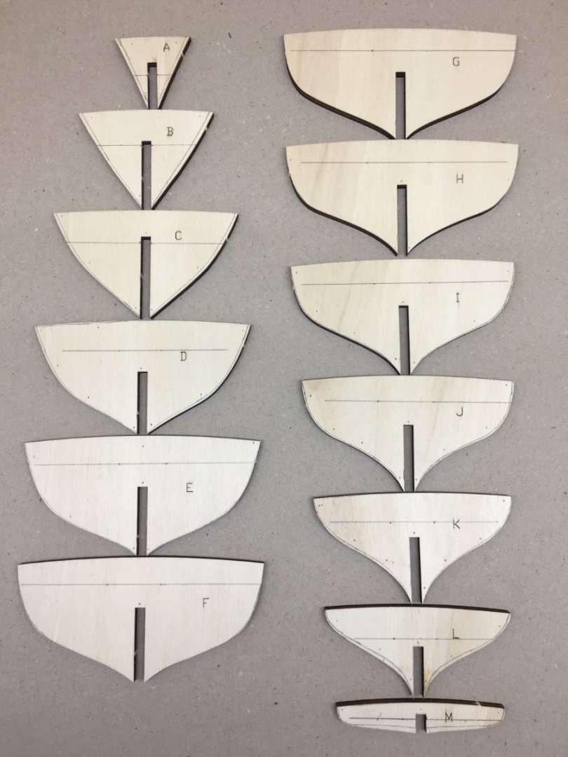
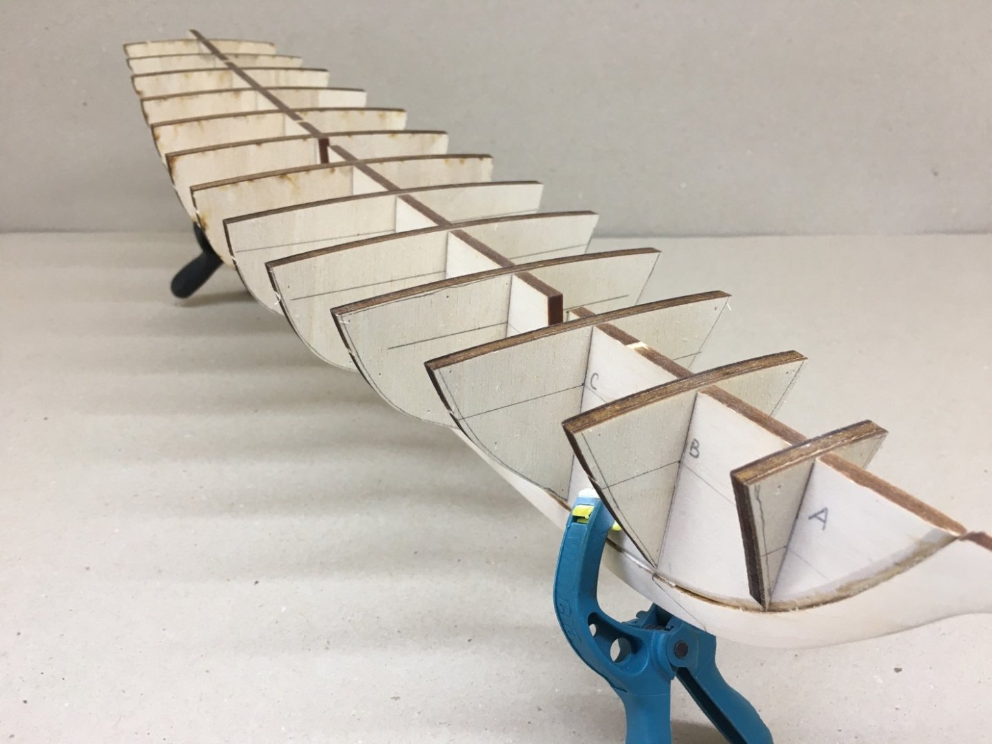
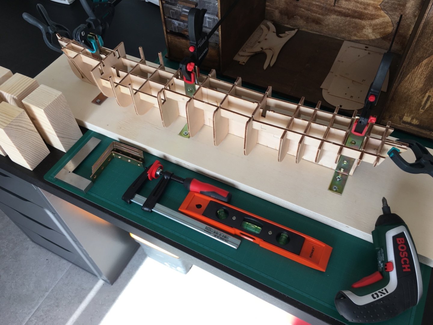
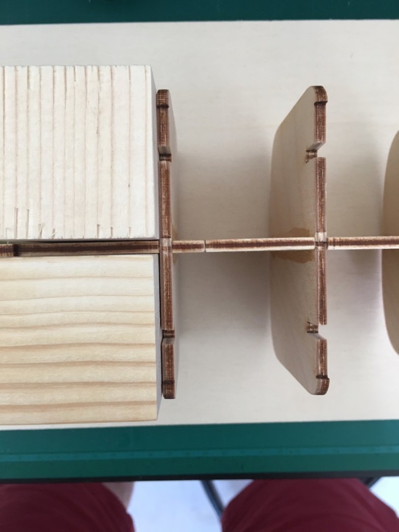
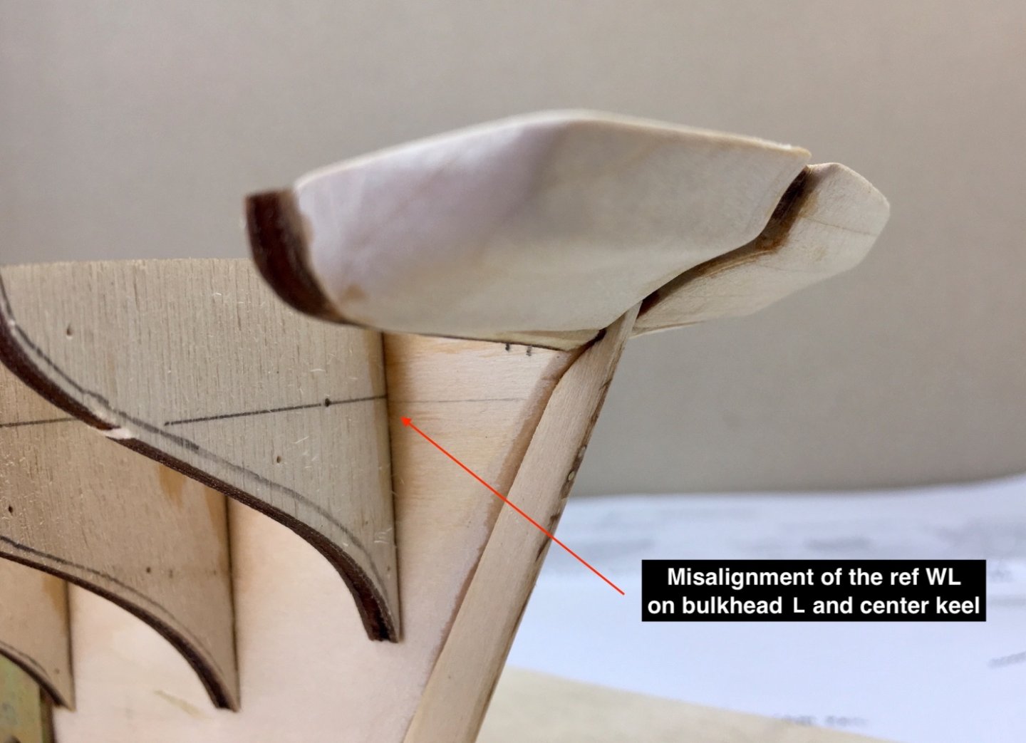
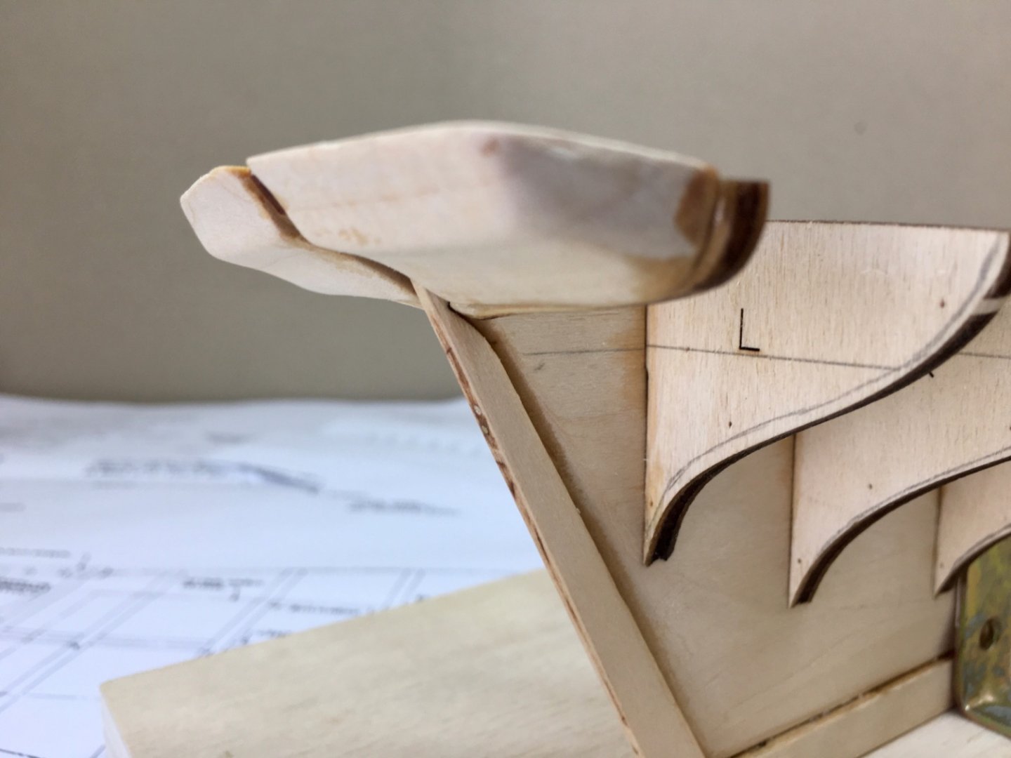
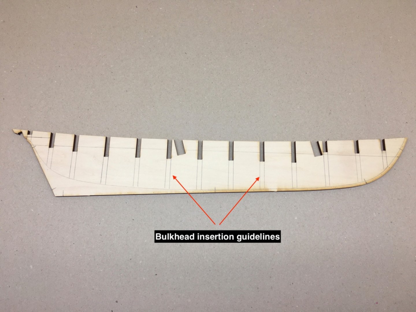
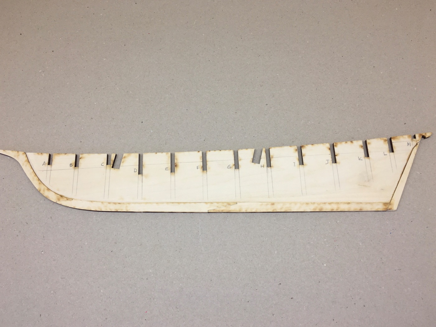
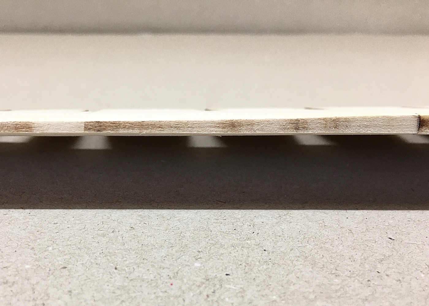
The kit has 13 bulkheads labelled from A to M , starting fore and ending aft. First the reference WL lines and beveling lines are transfered from the plans to the bulkheads. Bulkhead drawings are carefully cut out from a spare plan sheet and each one is laid on the bulkhead with care to align the midline reference mark on the plan copy and the midline point on the bulkhead insertion slot base. At that point the area outside of the beveling line on plan copy (both hull and deck sides ) must be cut in order to mark it on the bulkhead. Then the plan copy is fixed on the bulkhead with pins at various points and at least two of them must be on the reference WL. The beveling line is drawn on the bulkhead hull and deck edges with a fine tip (0.3 mm) pen following the edges of the plan copy. The paper is removed and reference WL is drawn with the same pen by connecting the two needle holes previously placed on that line. As seen on plan sheet 1 , the reference letters and beveling lines on bulkheads A-F must face forward and the ones on bulkheads G-M must face aft. After preparing all the bulkheads they are dry fitted to the center keel. At this stage insertion slot problems must be taken care with careful sanding. And also checking the alignments of Ref WLs on bulkheads and center keel. At slots bulkhead tops and center keel must be flush. If center keel level is below bulkhead level , it is OK , as the deck planks will lay on bulkheads. The instructions dictate to bevel the bulkheads BEFORE their final installation to center keel. Although this seemed somewhat unlogical to me, I tried it on bulkhead A. I immediately regretted doing it and had to shim the bulkhead later after final installment. I don't get the idea behind this dictation as the beveling of the bulkheads is the final stage before starting the hull planking and any positional installation problems arising after the beveling of bulkheads before installation, will surely cause a lot problems of trimming or shimming. I hope I made my reason for leaving the beveling of bulkheads after final installment clear. Dry fitting of the bulkheads Now comes the permanent installment of the bulkheads to center keel. Unfortunately I did not take pictures at this stage but some photos from my previous two build will give you some idea how I did it. First you prepare a suitable sized baseboard. You need some L shaped metal brackets and nuts and bolts to fix them on the baseboard. By placing the metal brackets (at least three ) at suitable places along a drawn midline and fixing the center keel is the start. You use suitable size squared wood blocks when fixing the bulkheads and start placing them from bow , gradually moving back to stern. I use Titebond yellow wood glue to the connection surfaces and add liquid CA later with fine tip to the connection lines. Here are some pictures from previous builds. The first three is from 'Panderma' and the remaining two from 'Sunrise' (Maine Lobster Boat). This model was also fixed by bolts passed through the center keel. After the final installment of the bulkheads and before the beveling of them, I prepared the two filler blocks to shape the counter and transom at stern . For this procedure I cut the necessary drawings from the plan, glued them on card board and transferred them to two suitable sized basswood from kit stock. Using Dremel micro hand piece and various size sanding tips I first carved out the rough shape starting with the starboard side. After the rough sanding came the fine sanding stage mostly done by hand-held sandpapers. The final shaping was done with holding starboard and port sides together and by trying to give identical finishing. Then they are glued to the aft of bulkhead M on their forward looking faces and to center keel on midline. After the installment of the blocks. Here you can see the metal L brackets I used for stabilazing the center keel. Here you can see a minor misalignment of the Ref WLs on bulkhead L. I was lucky it did not cause a major final problem in the end. Next post will be beveling of the bulkheads and starting of the hull planking.


- 114 replies
-
- 4
-
-
- Pride of Baltimore II
- Model Shipways
- (and 1 more)
-
I hope indeed it does…..
-
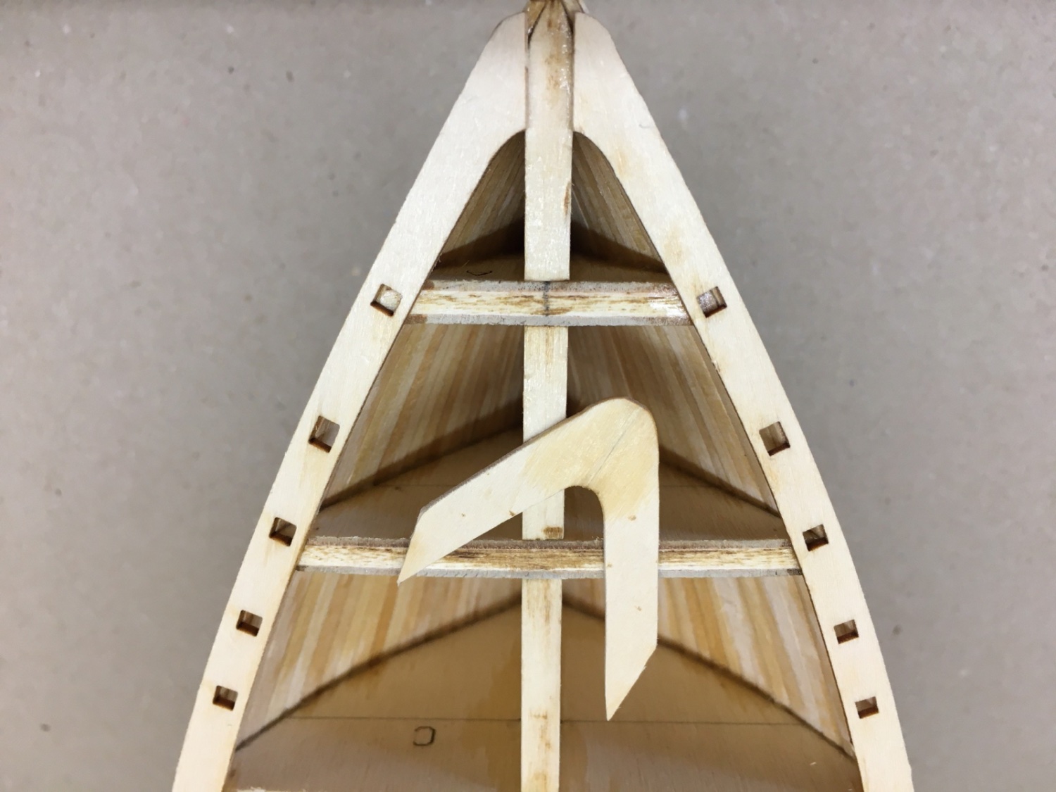
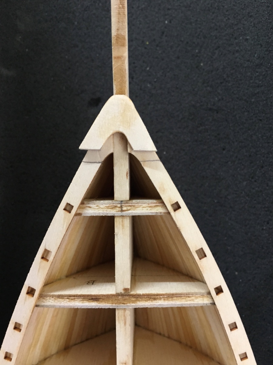
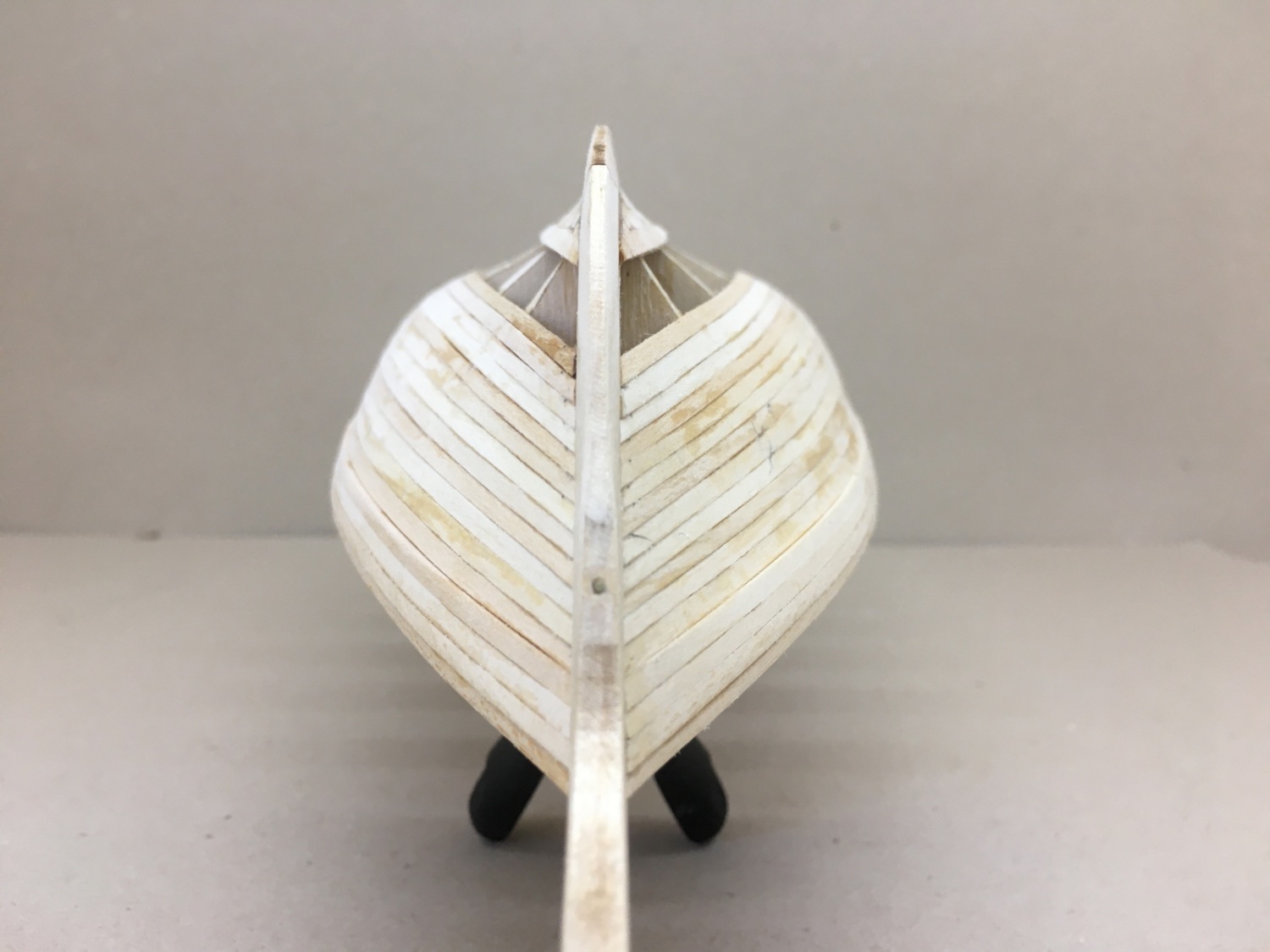
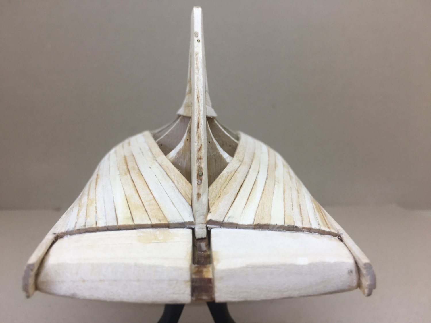
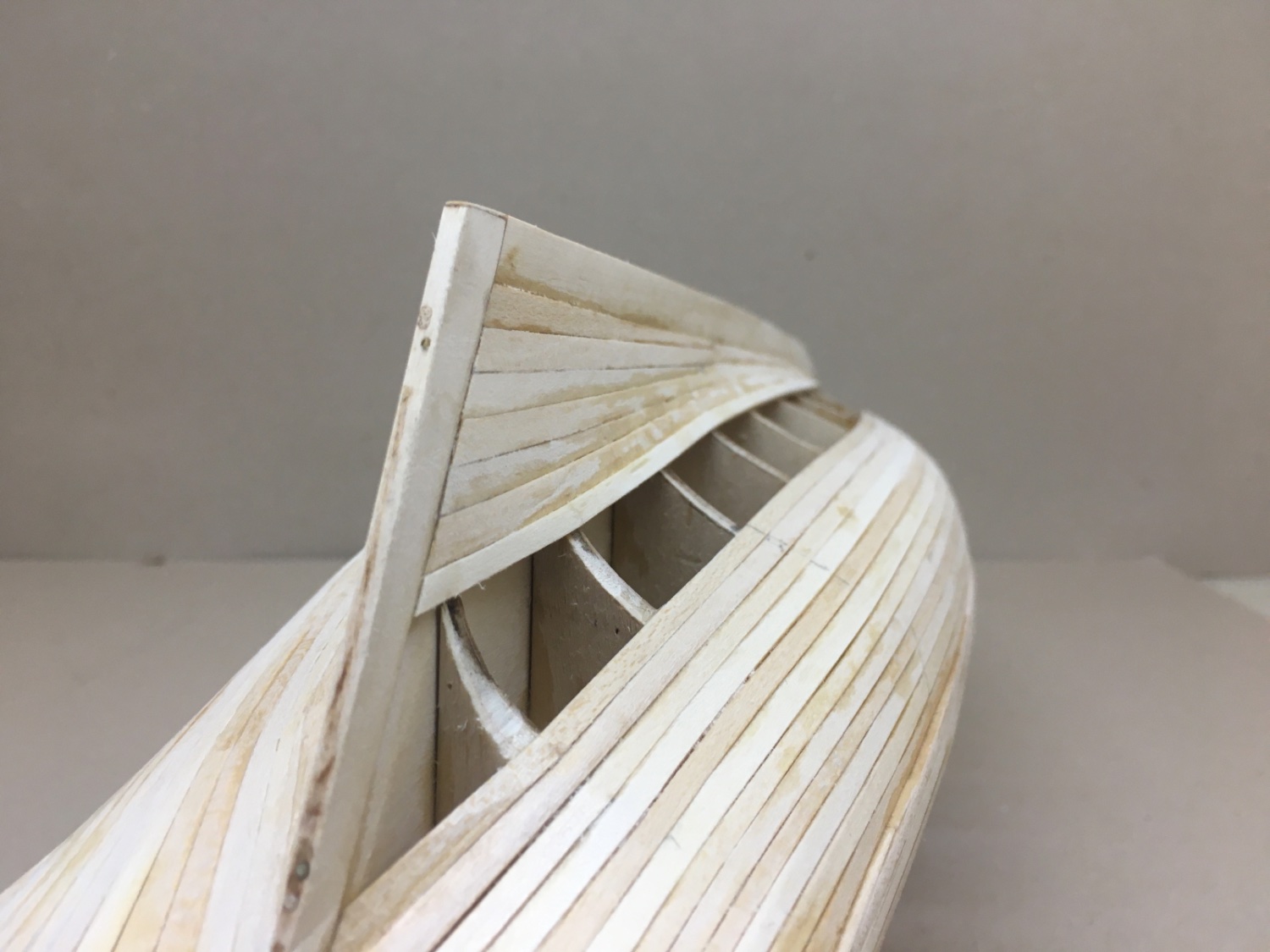
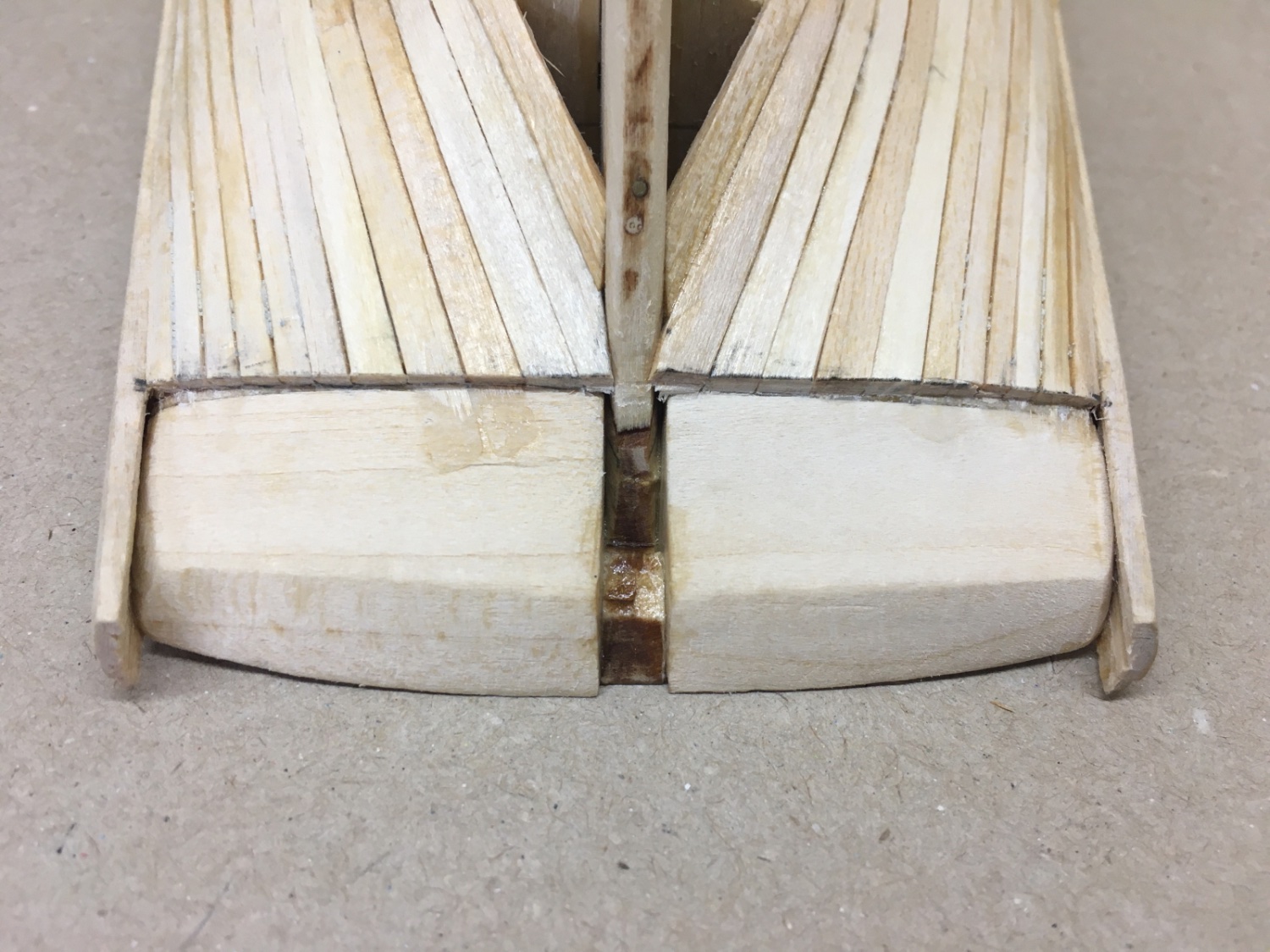
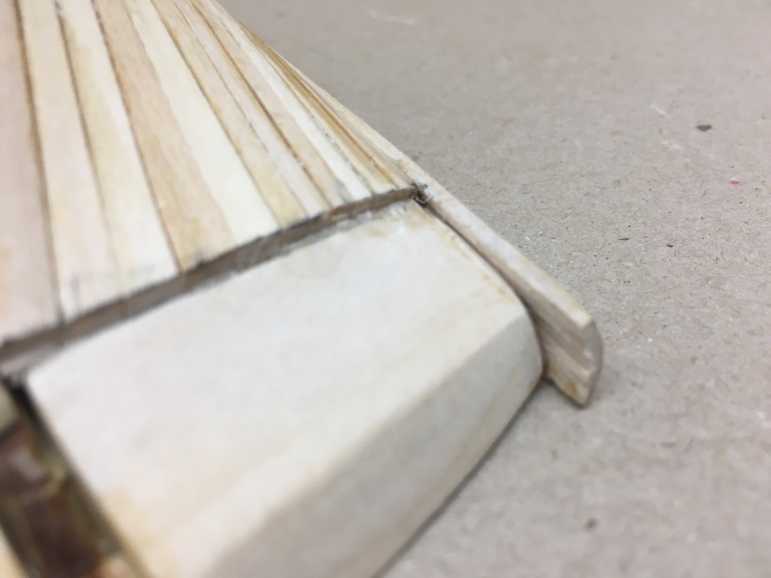
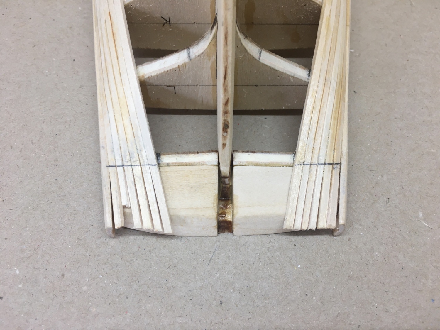
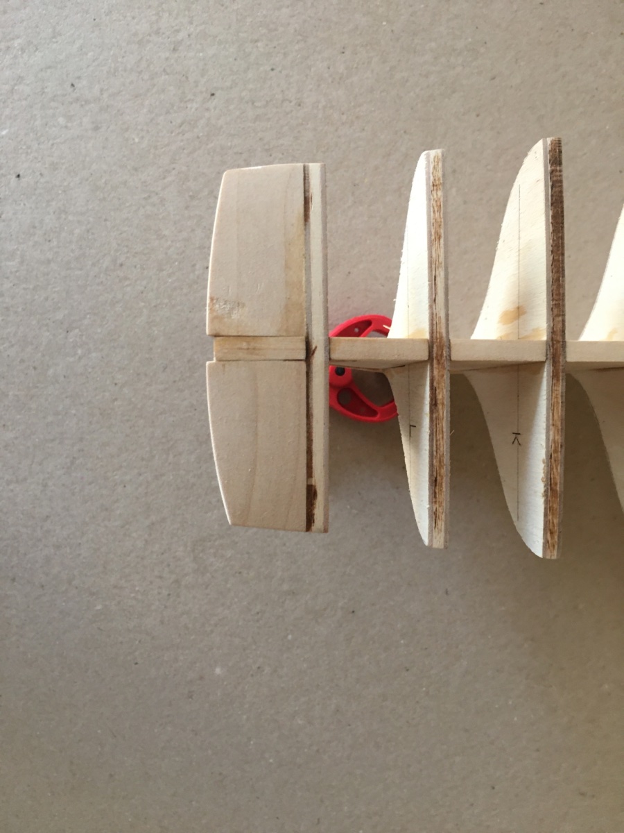
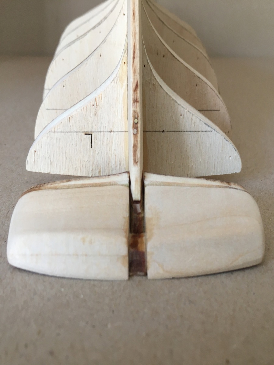
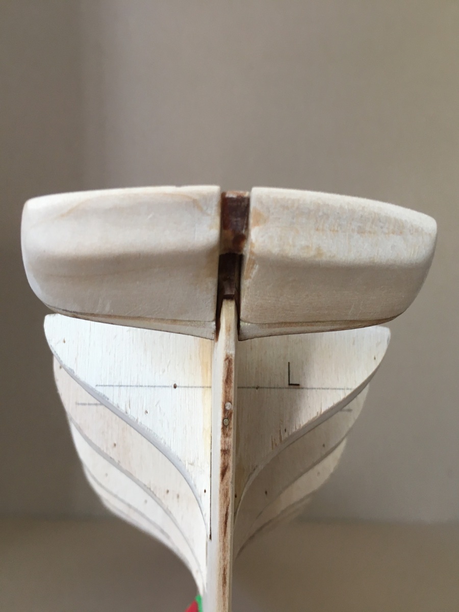
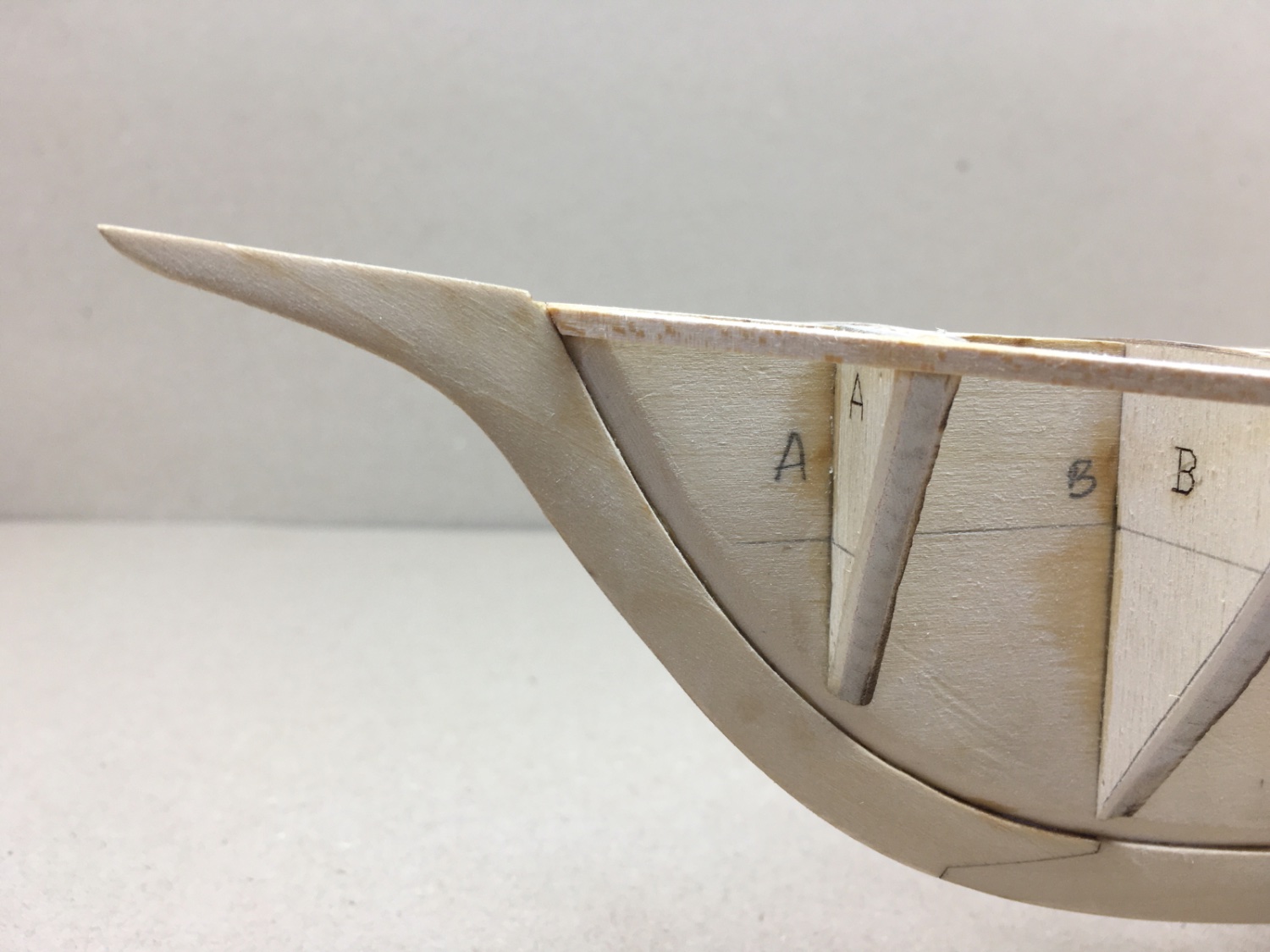
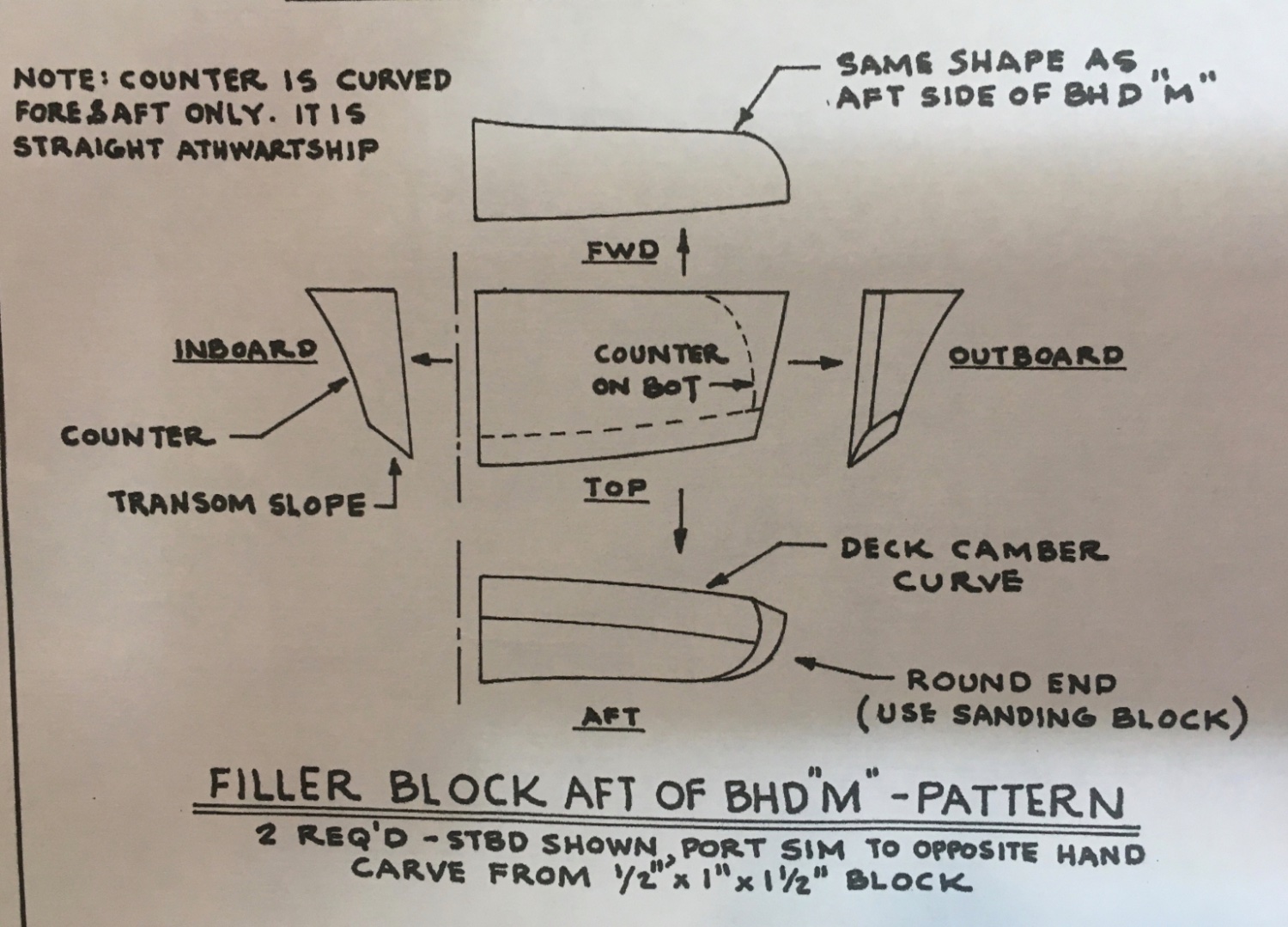
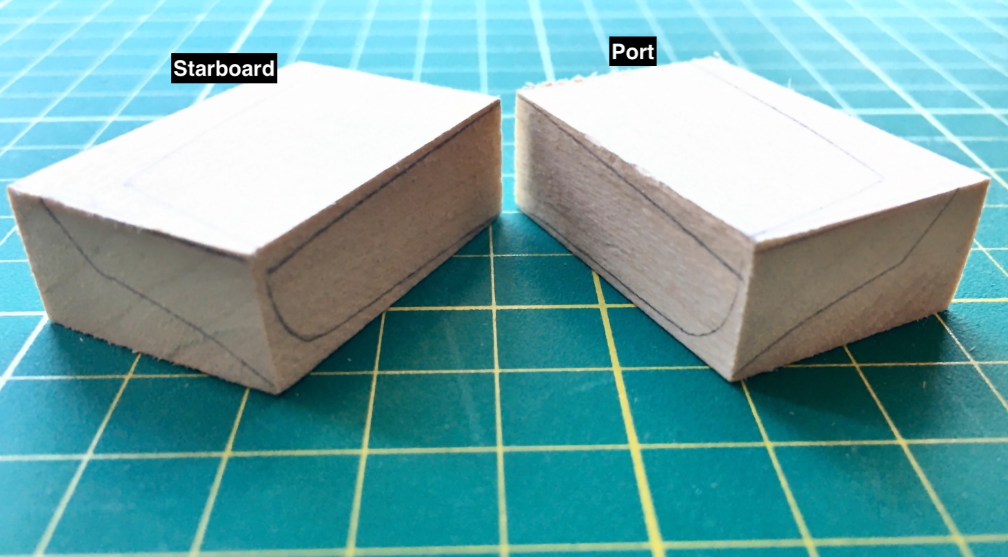
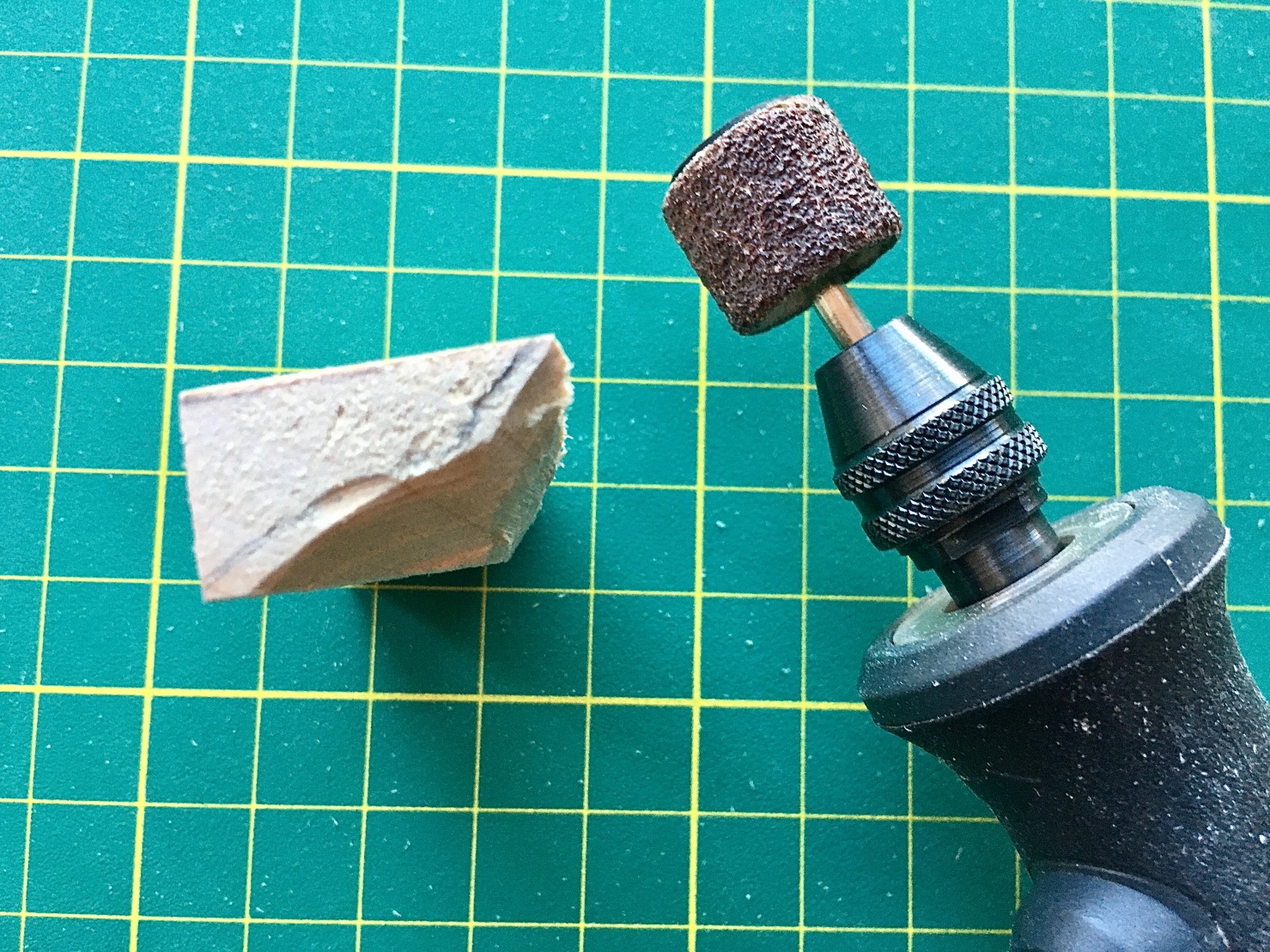
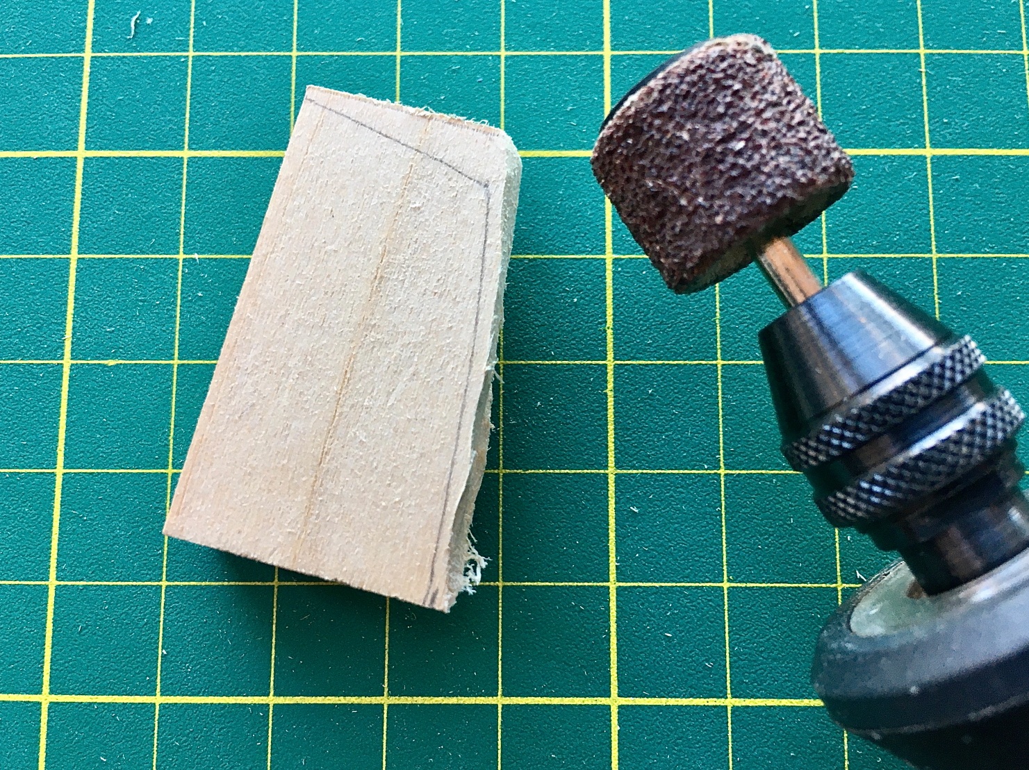
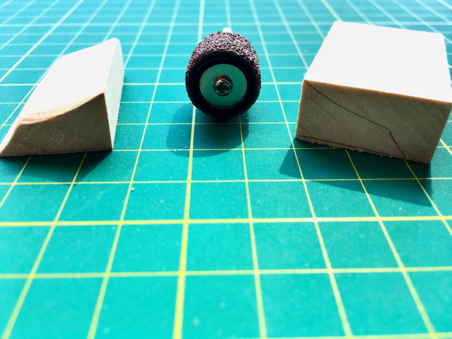
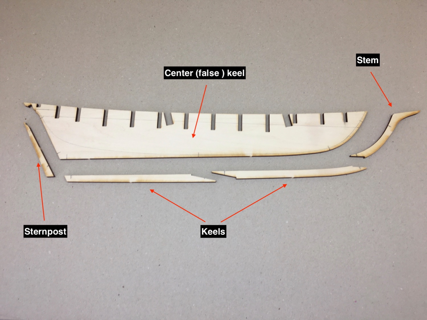
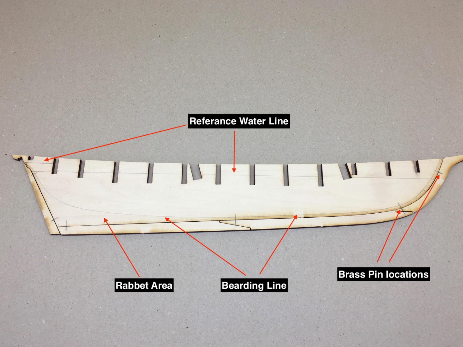
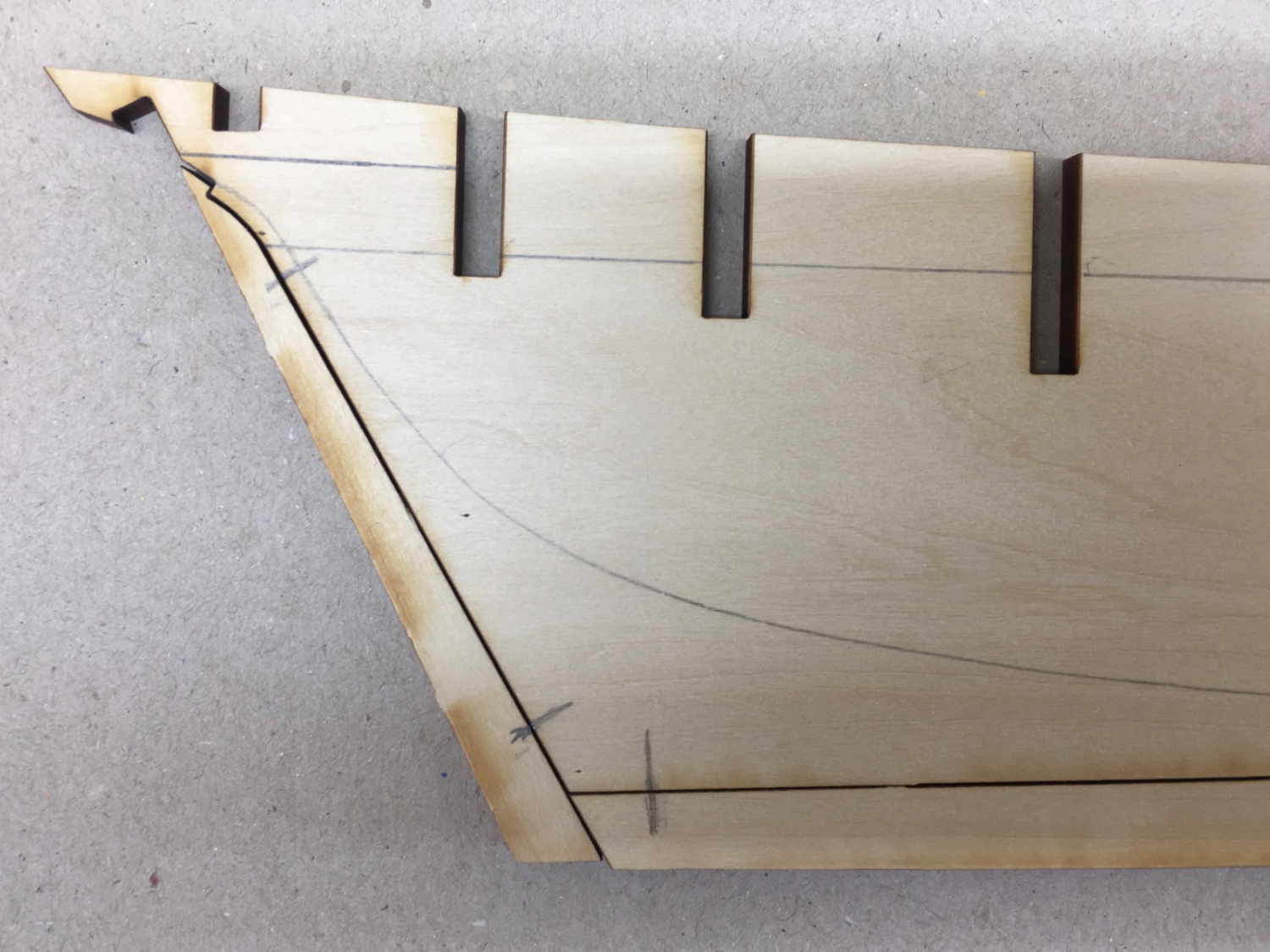
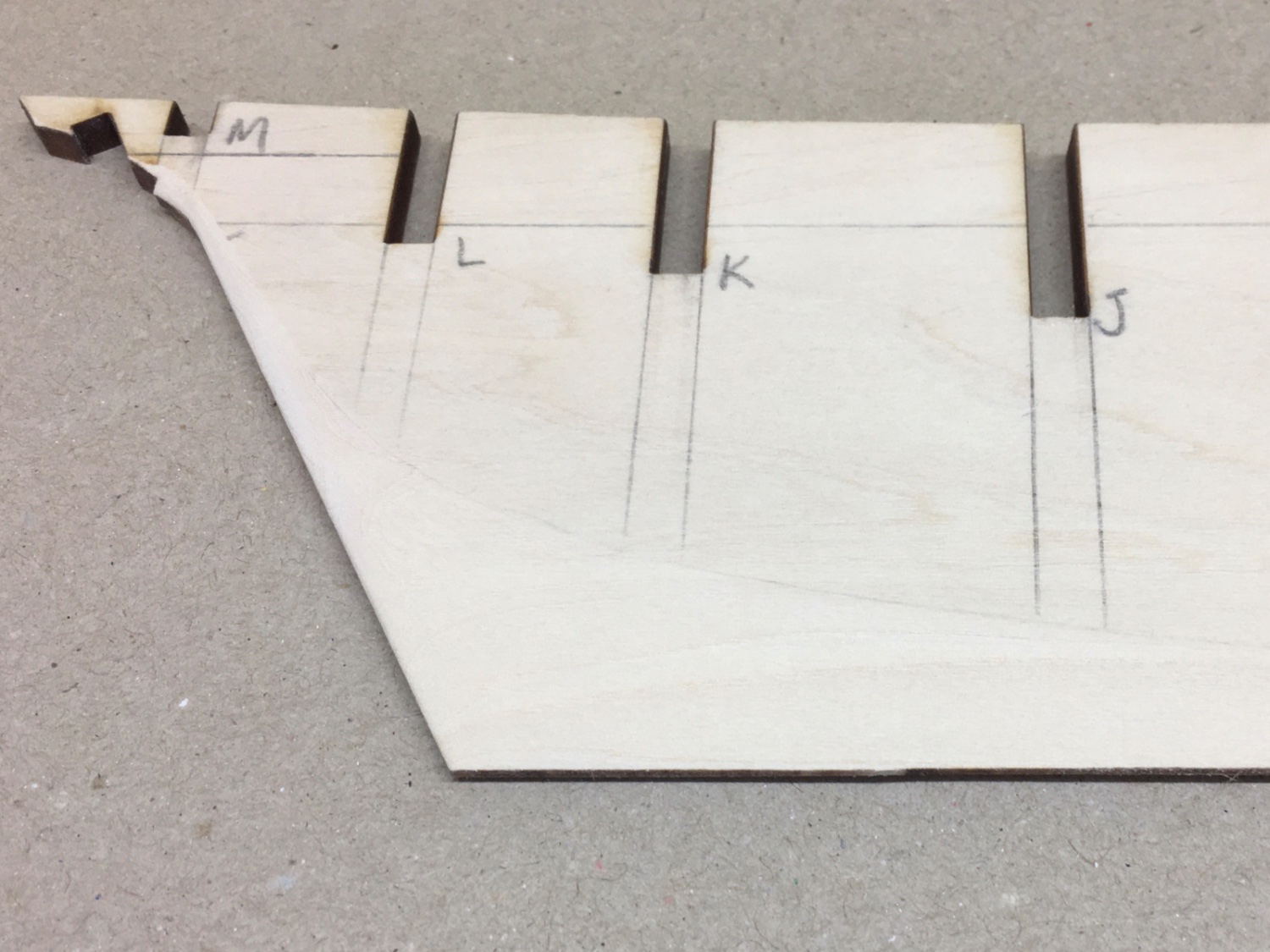
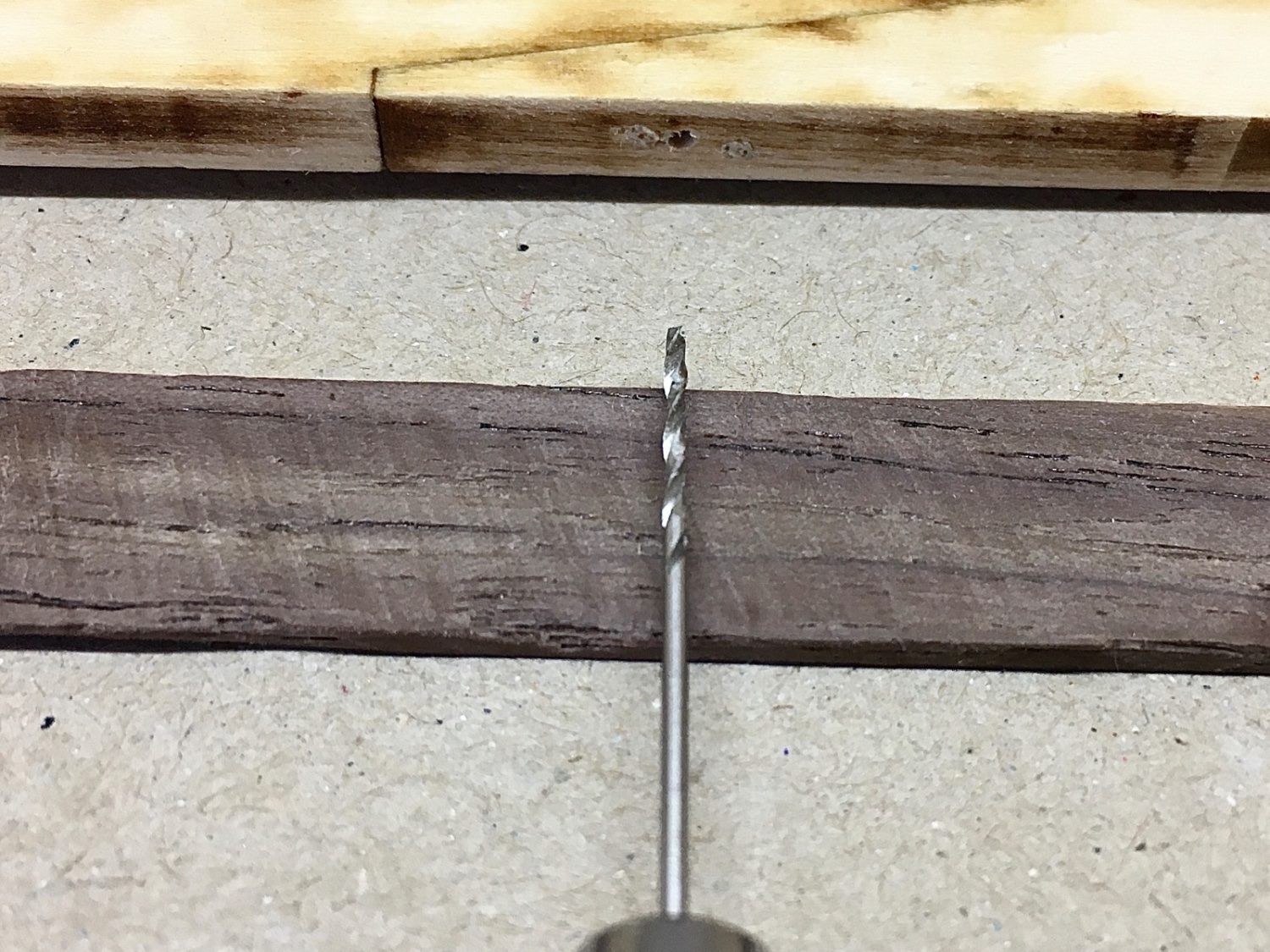
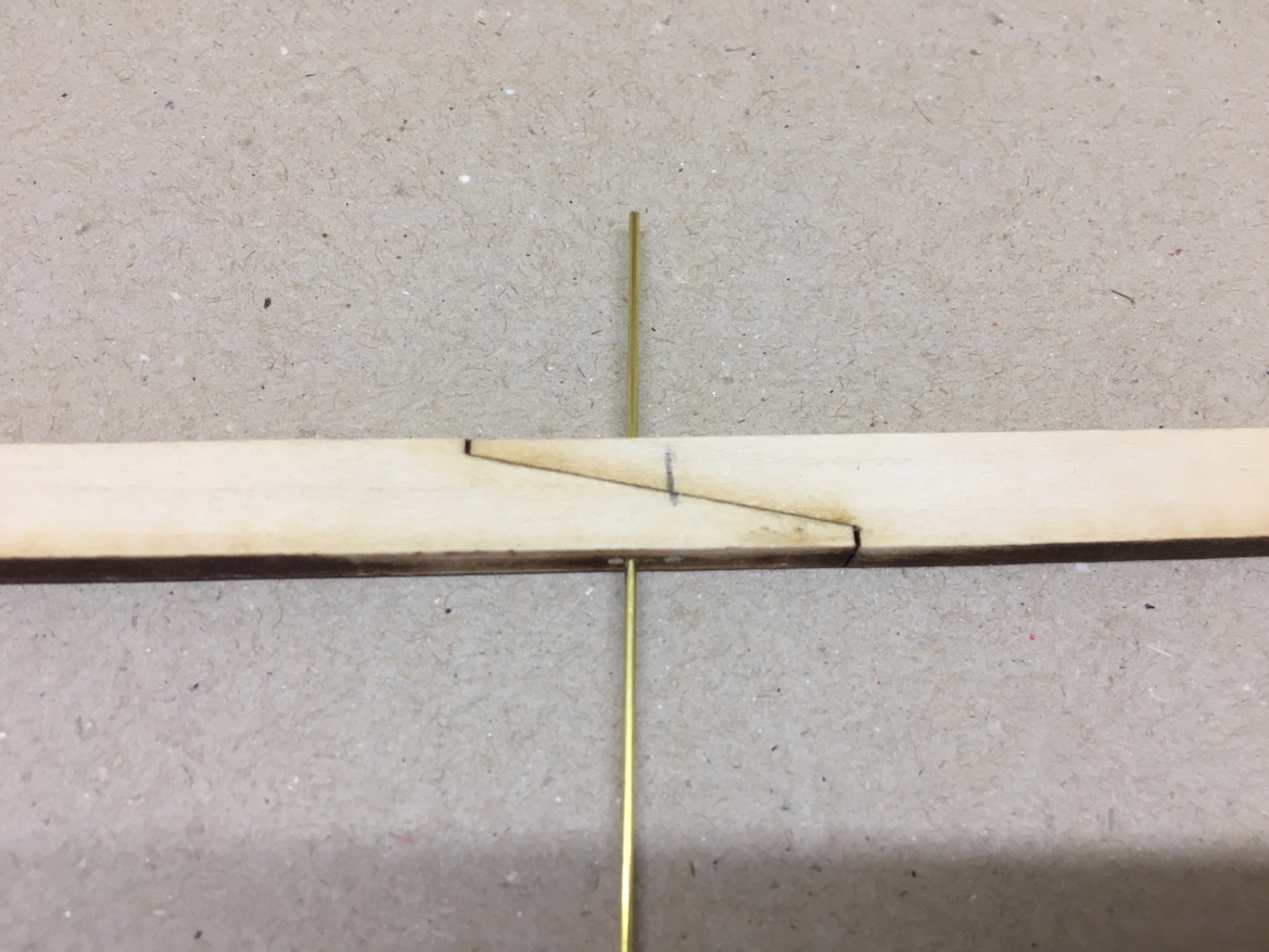
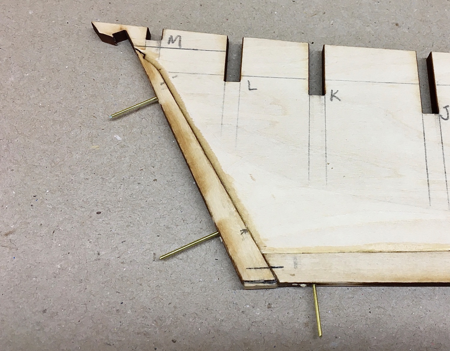
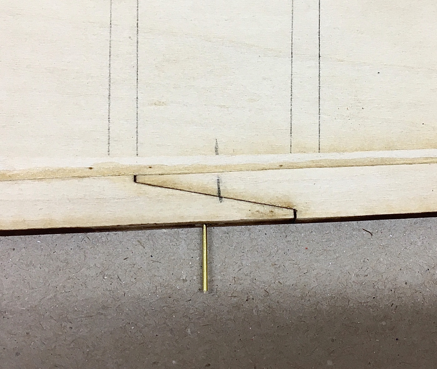
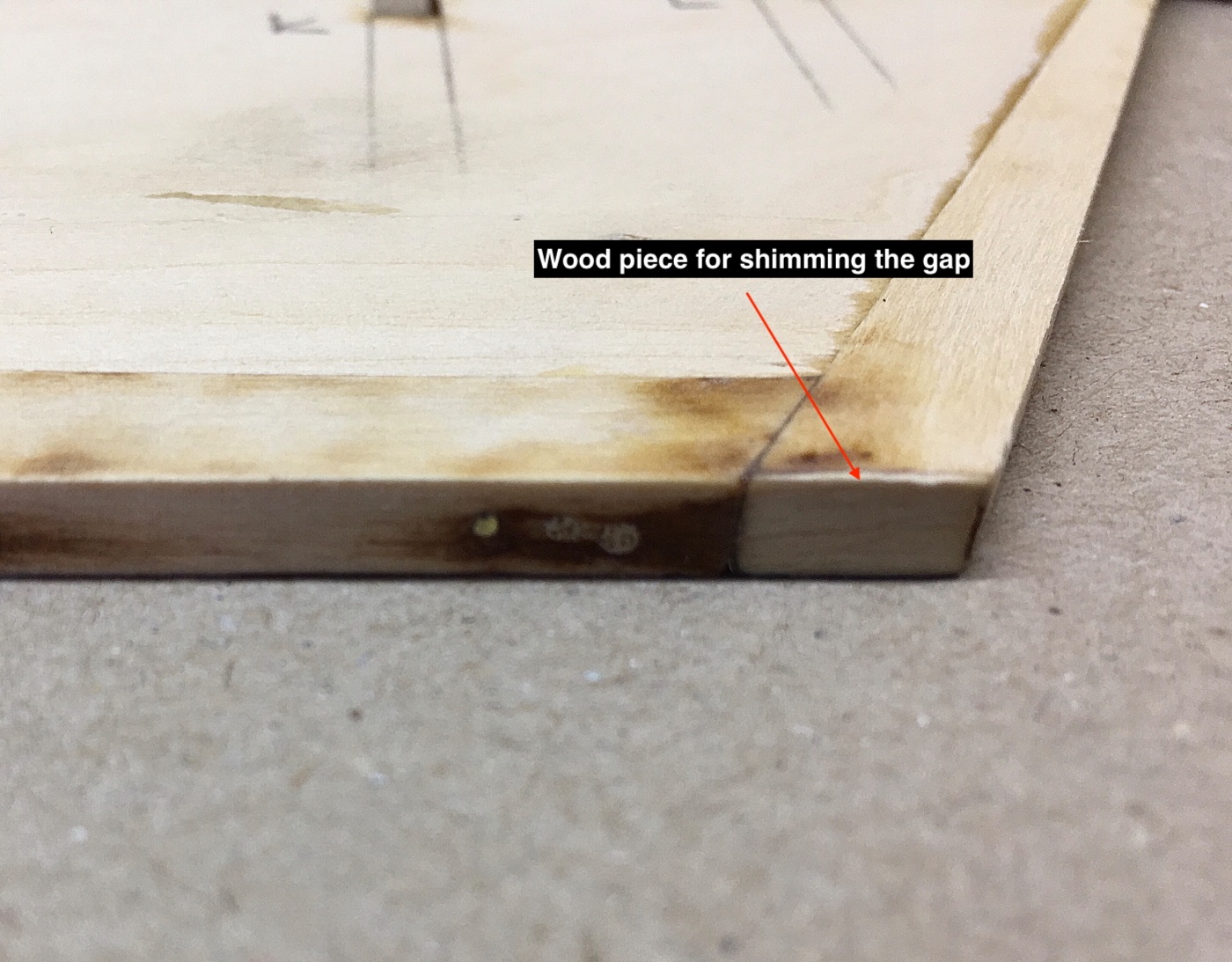
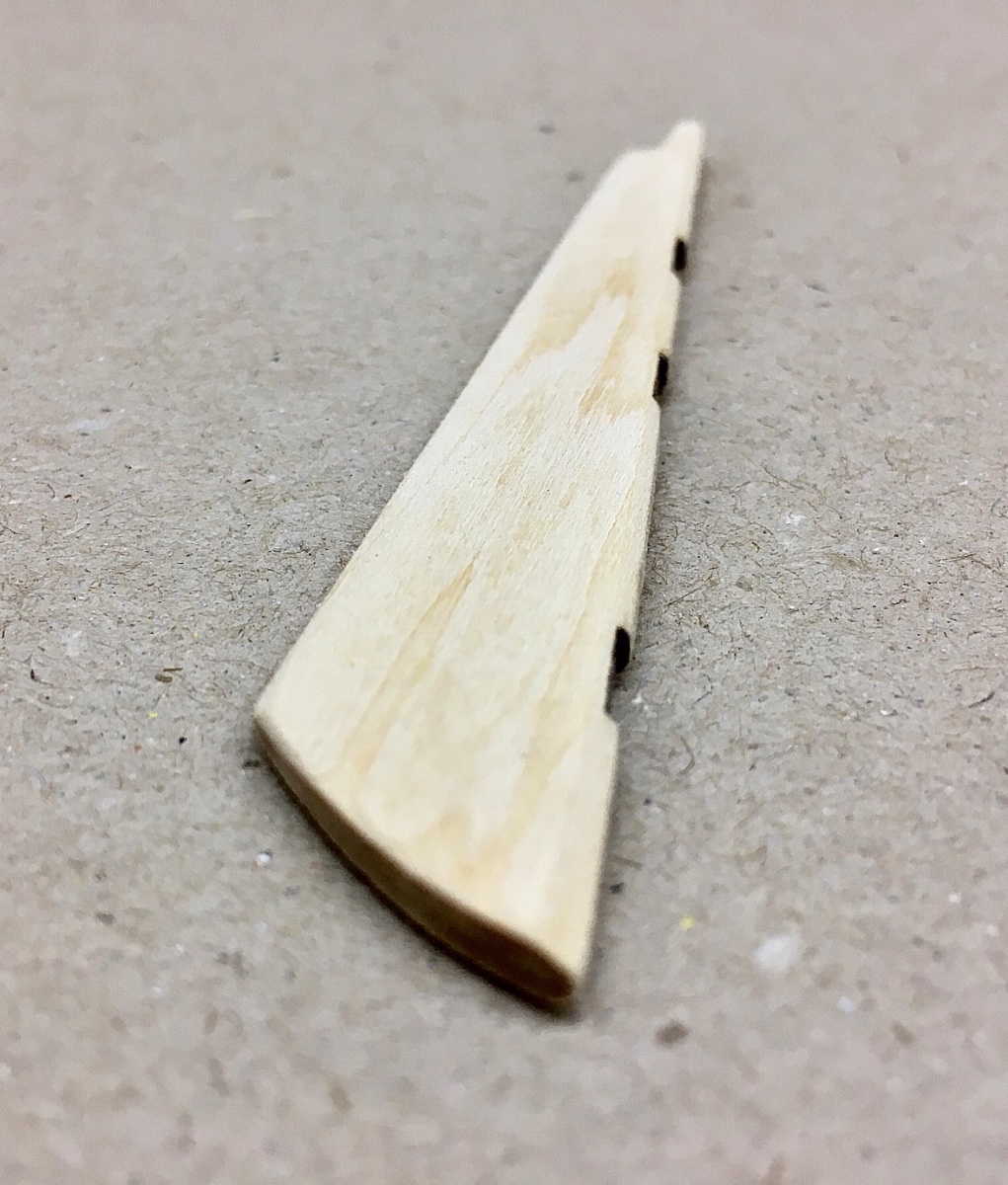
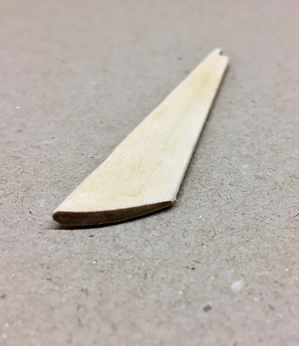
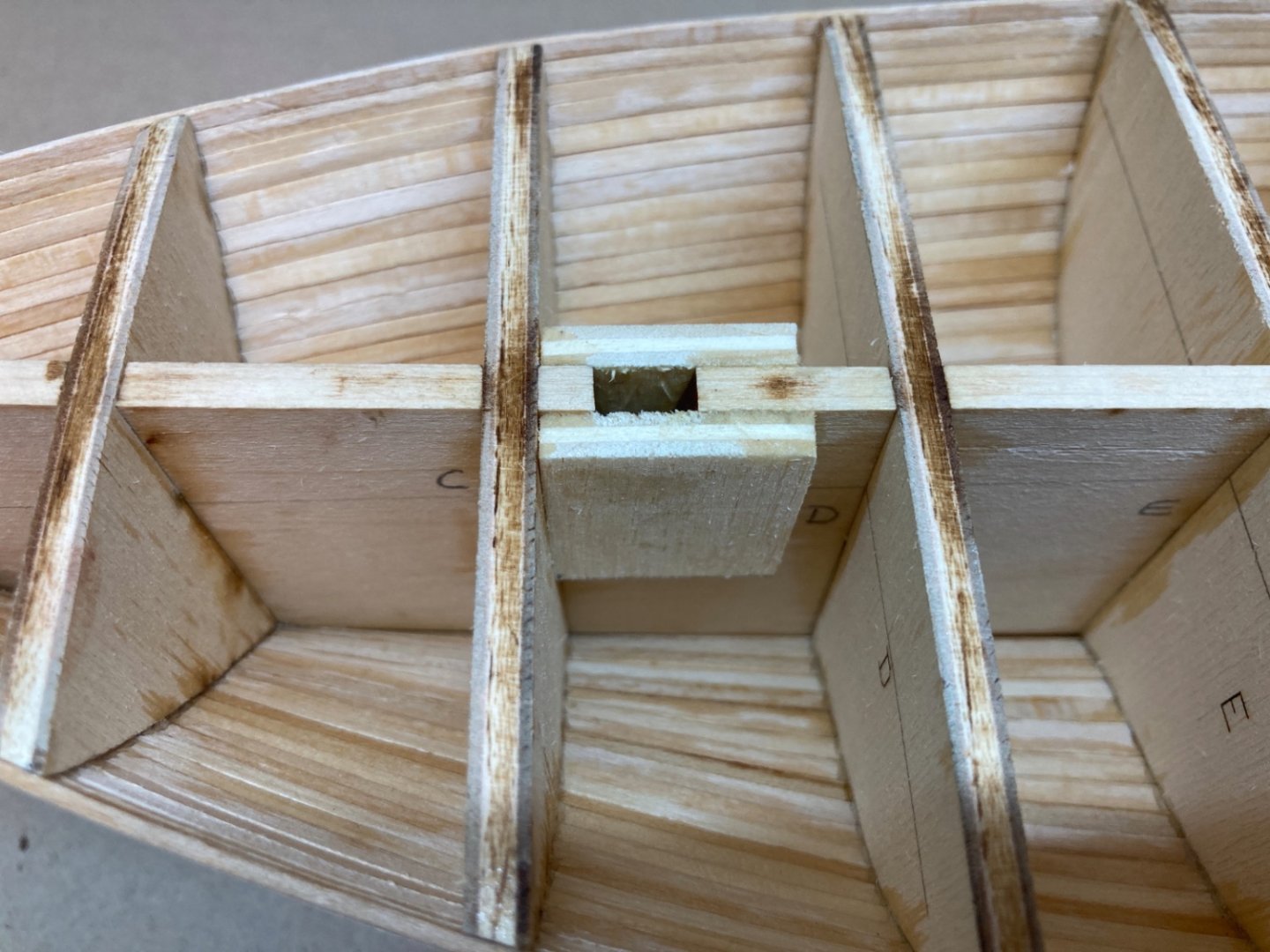
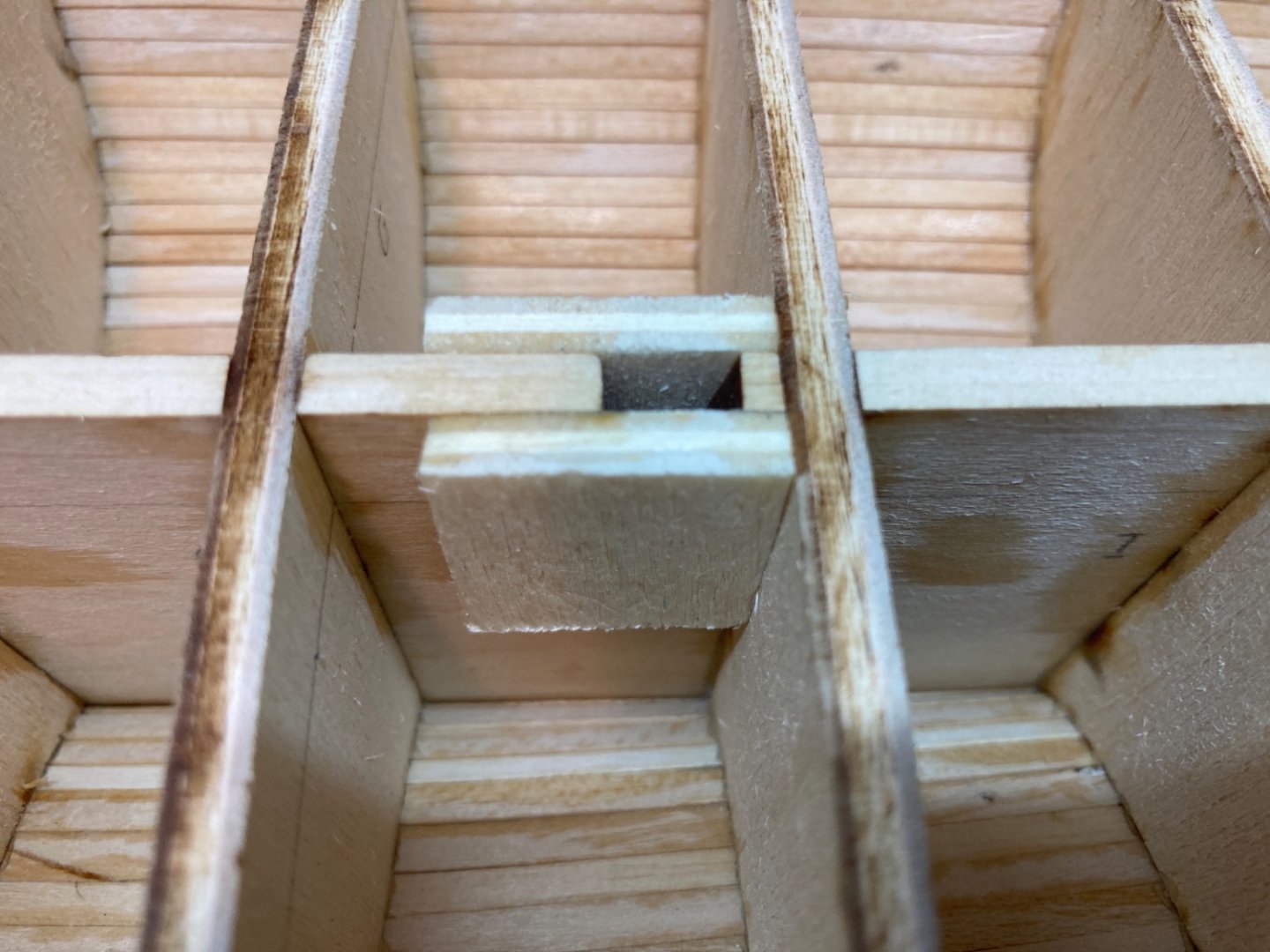
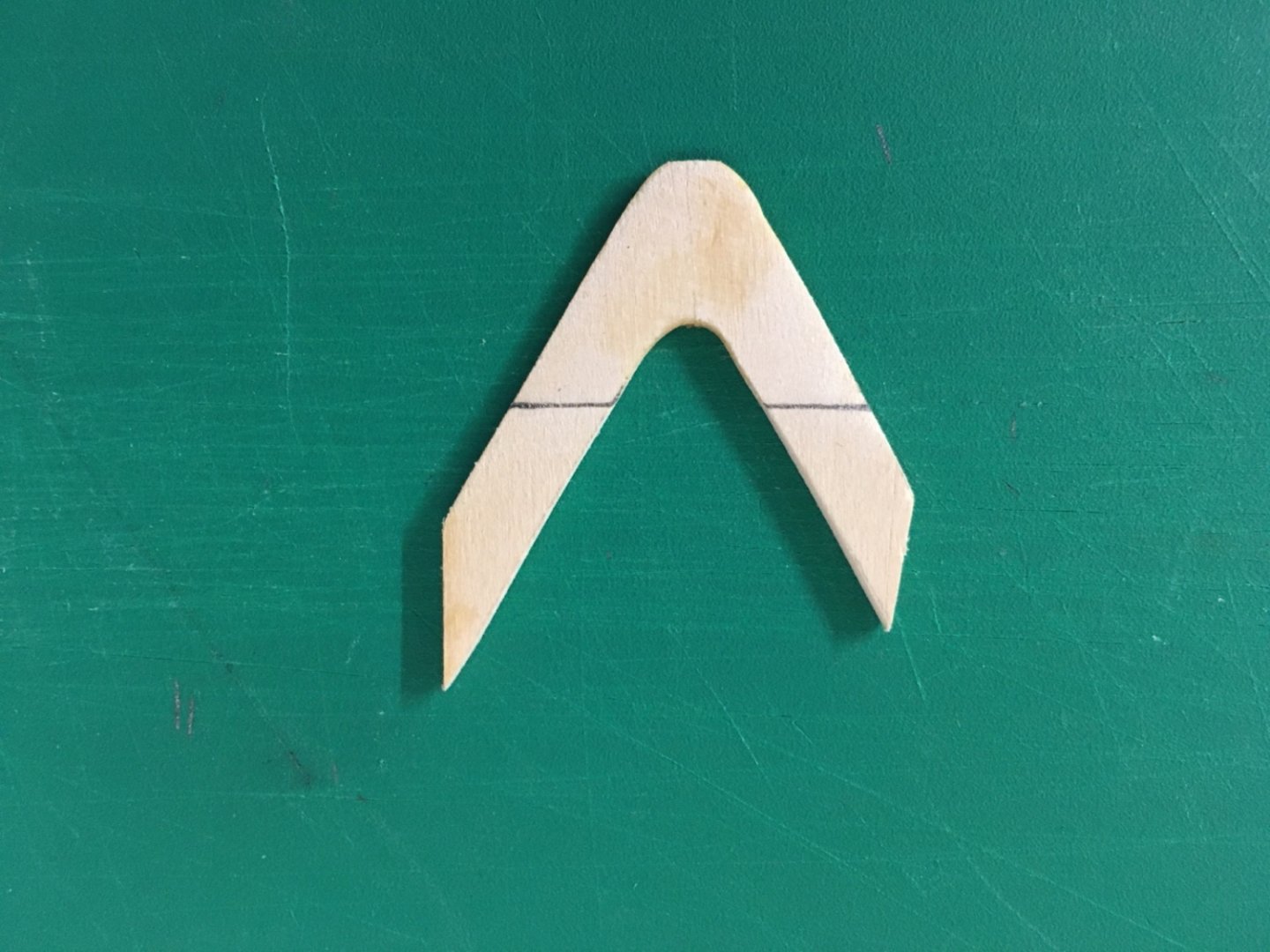
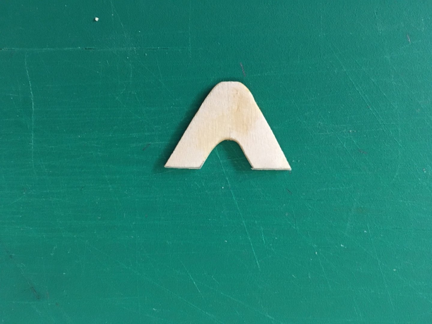
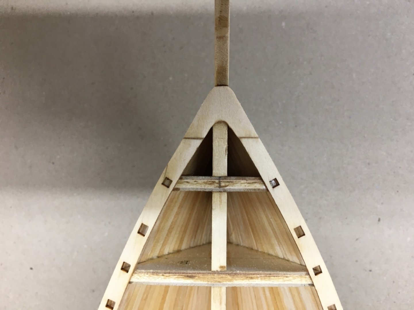
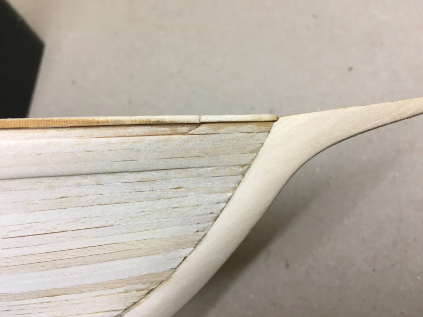
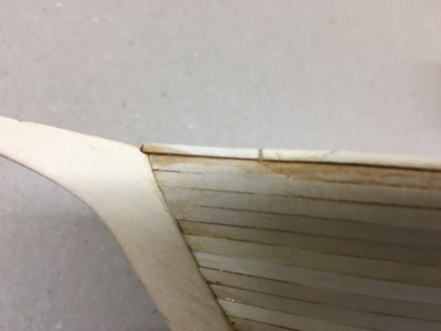
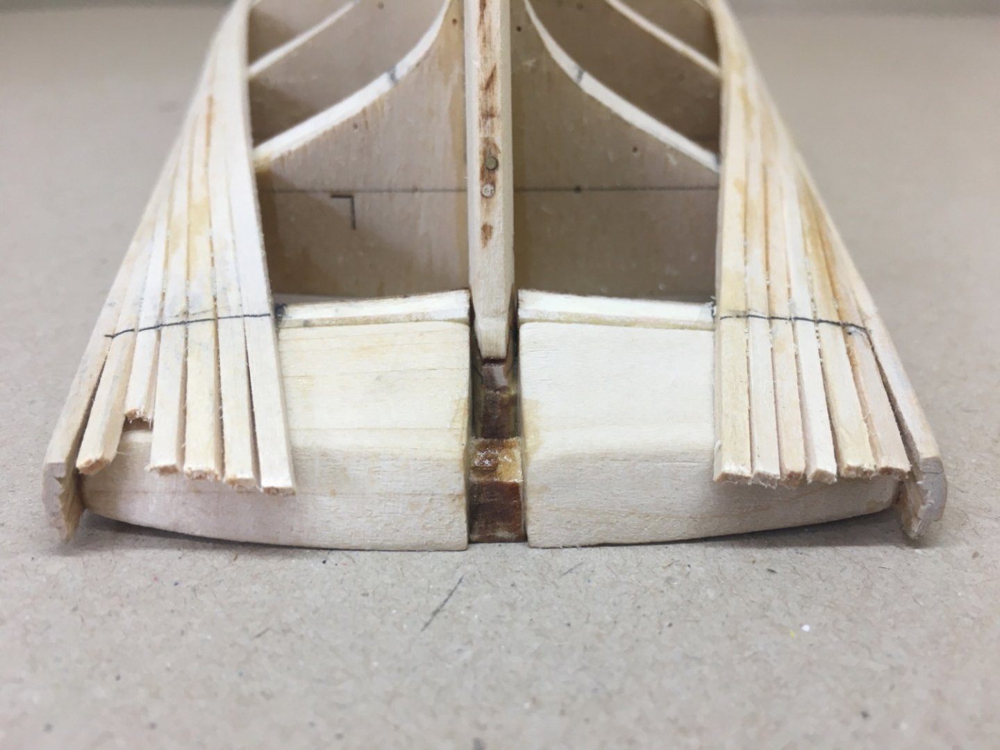
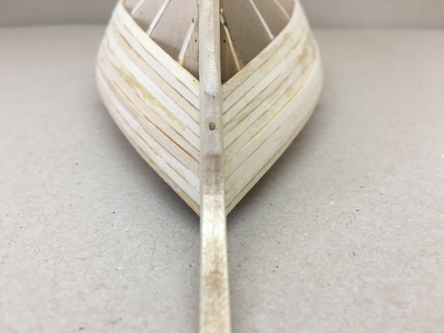
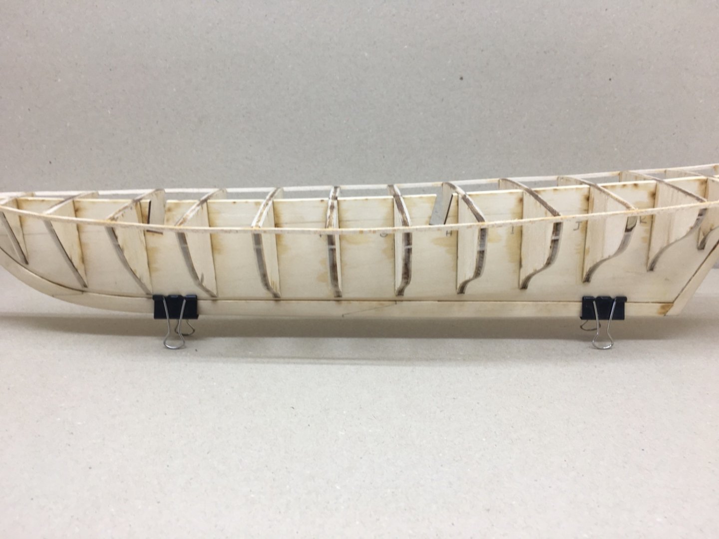
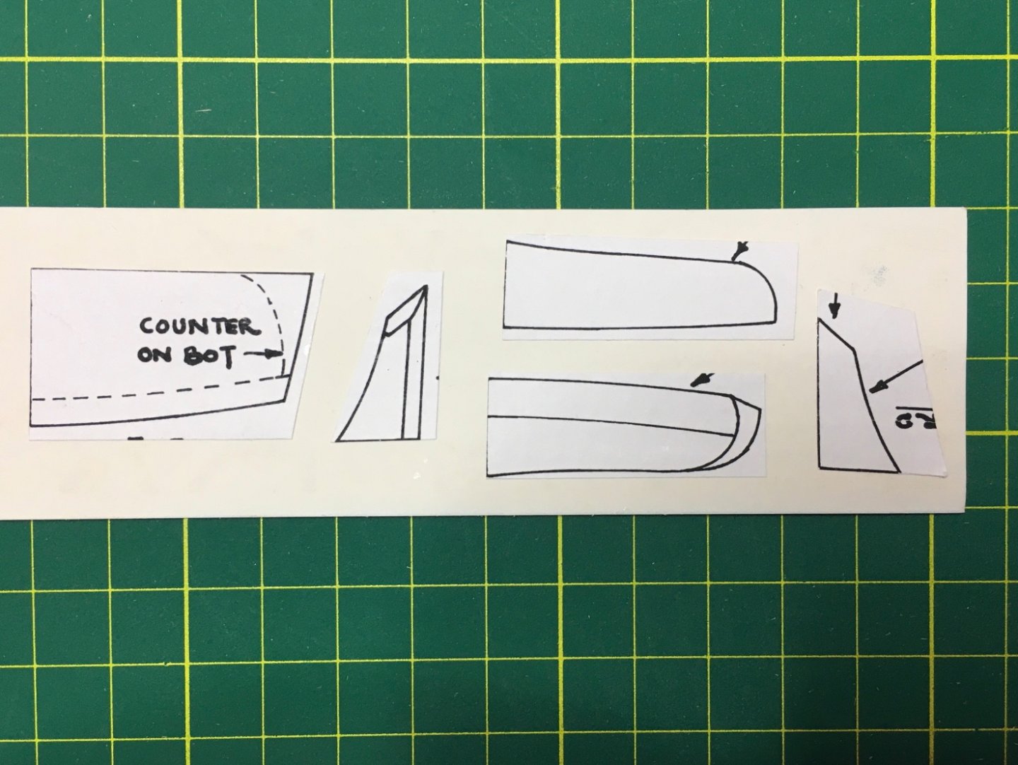
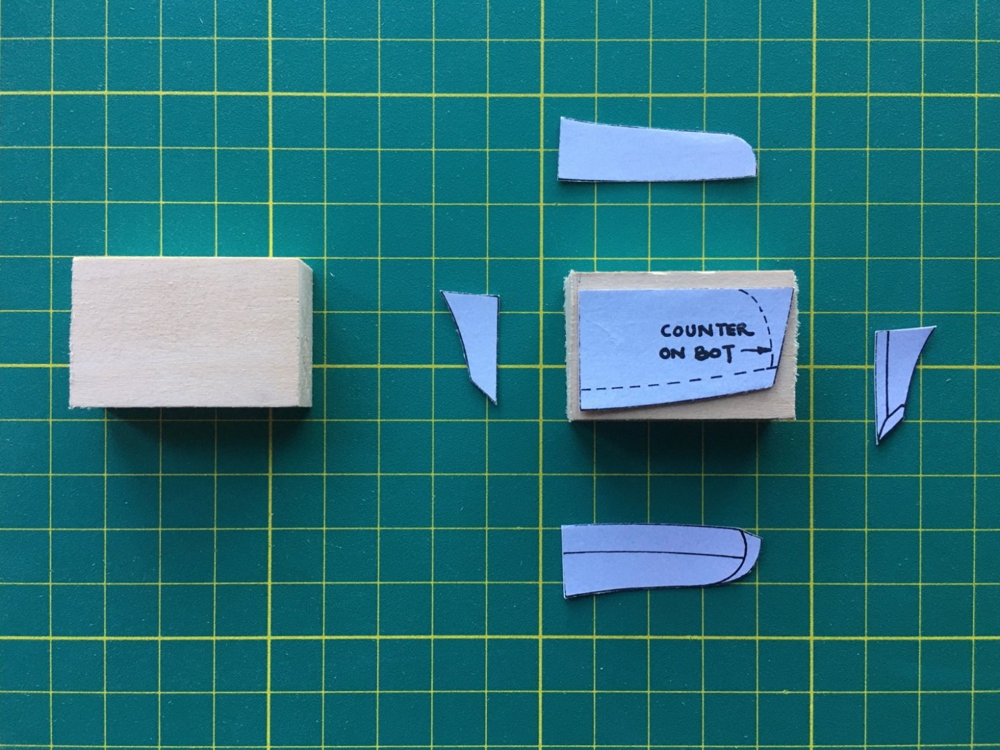
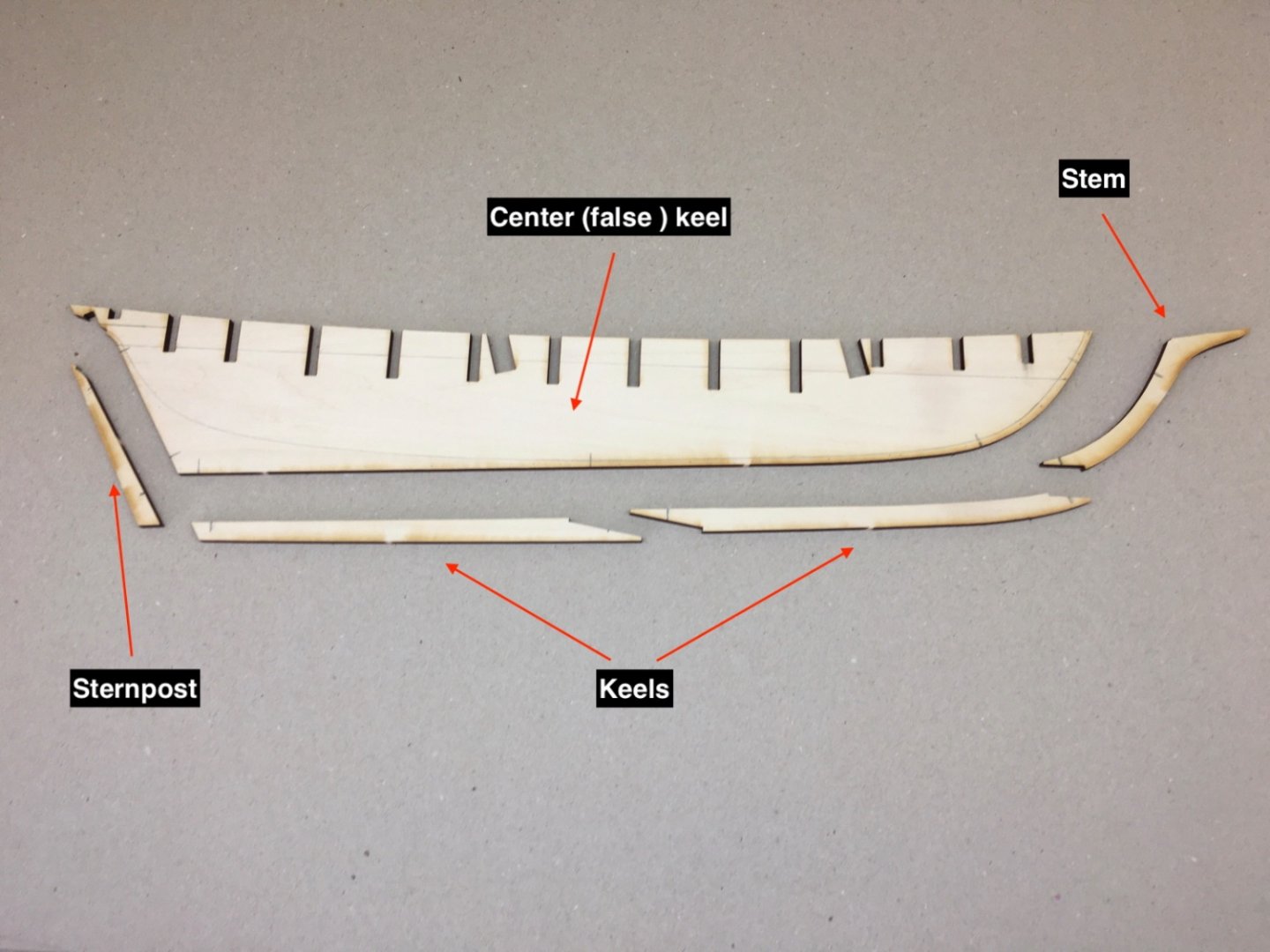
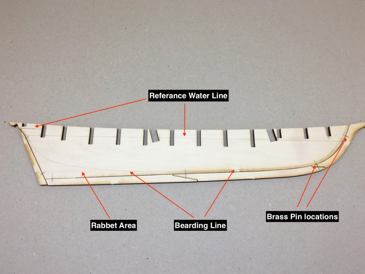
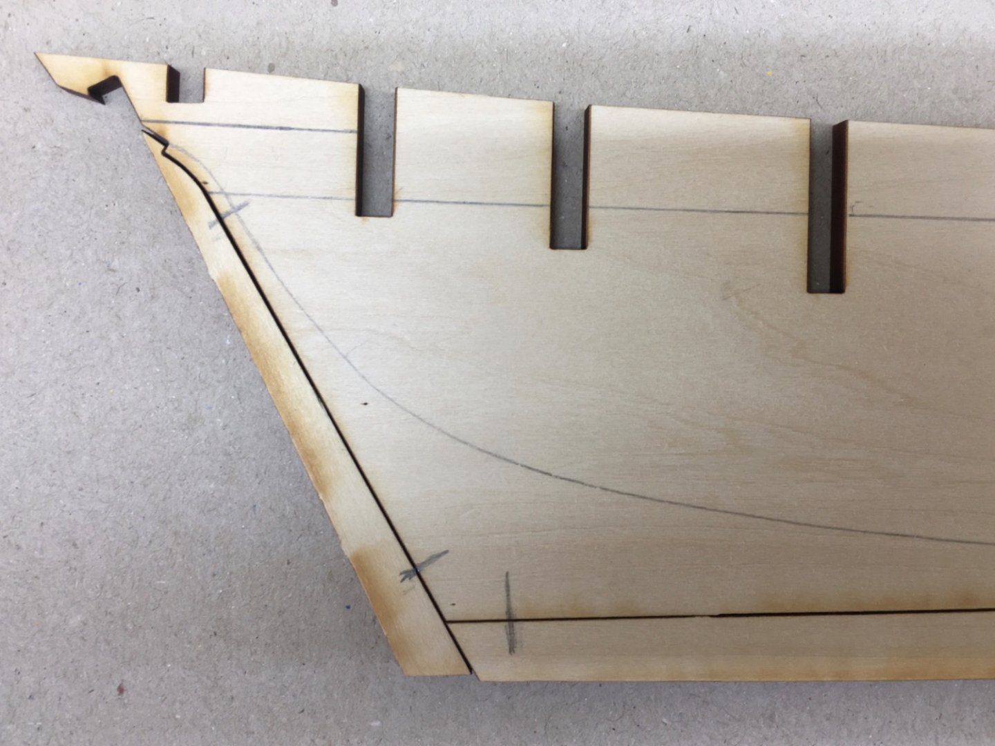
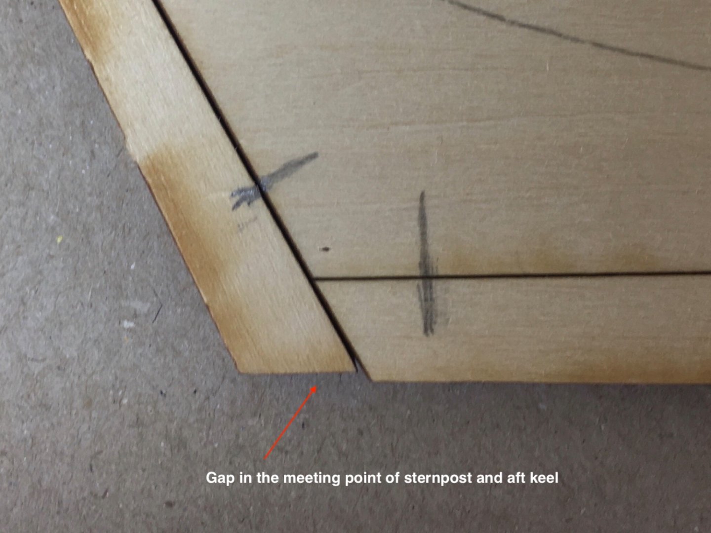
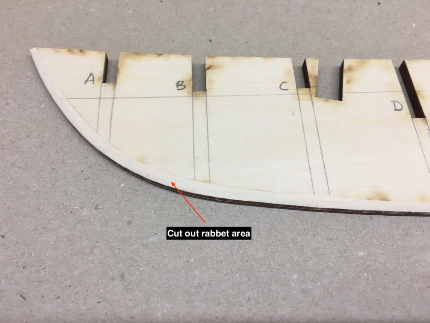
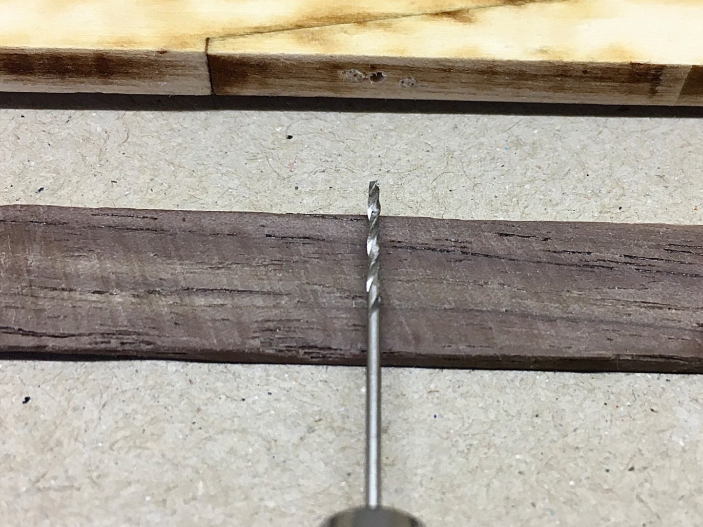
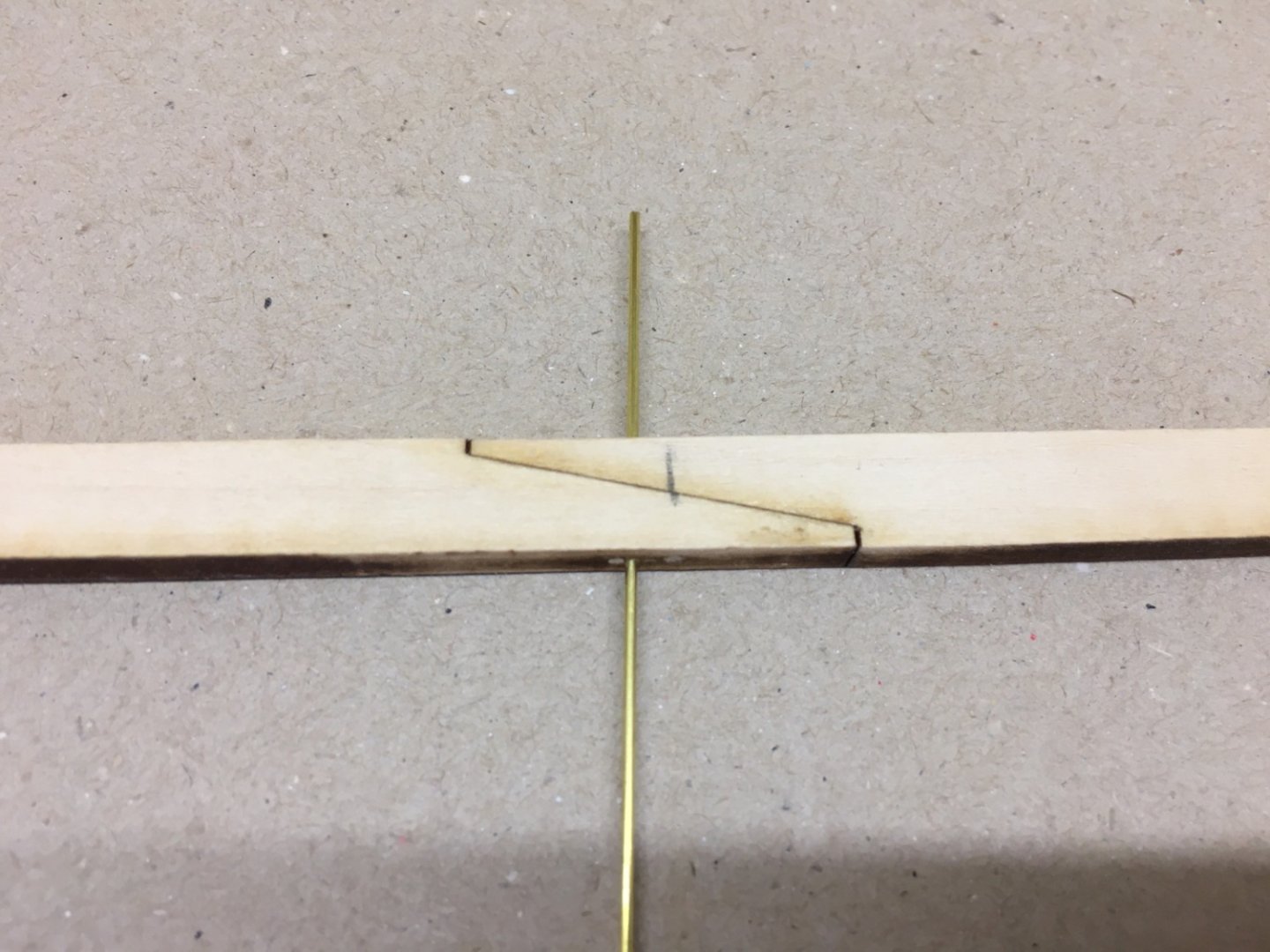
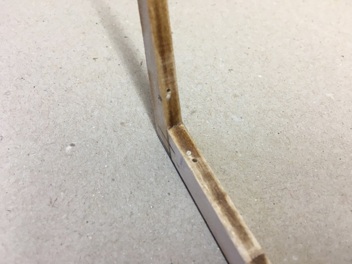
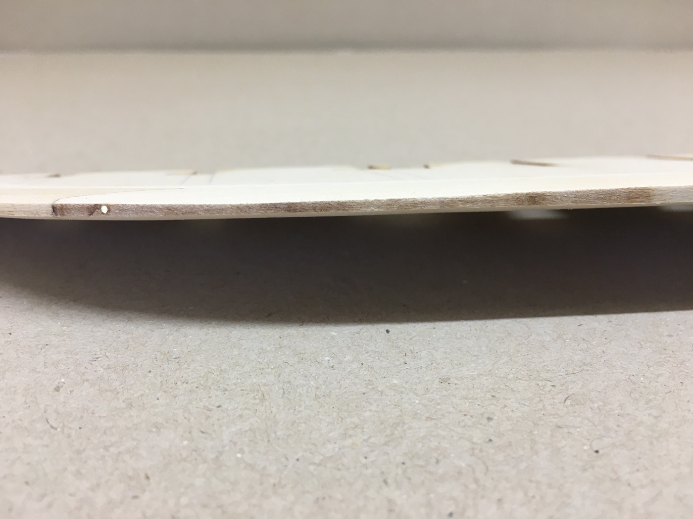
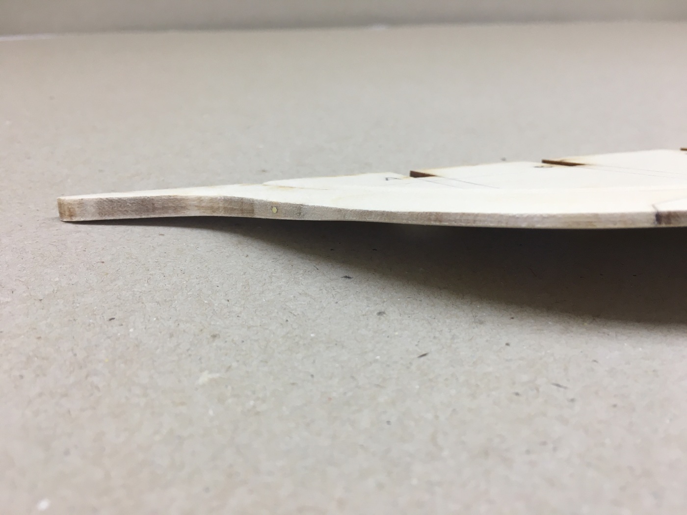
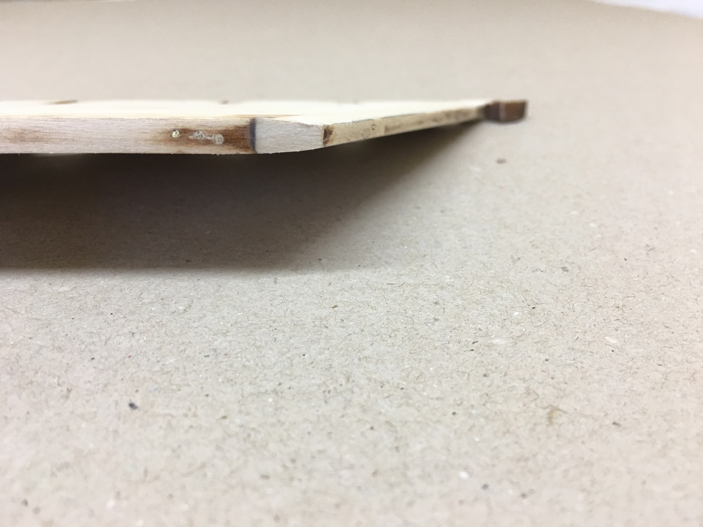
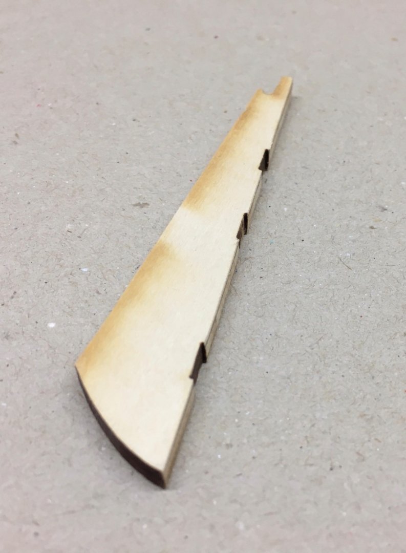
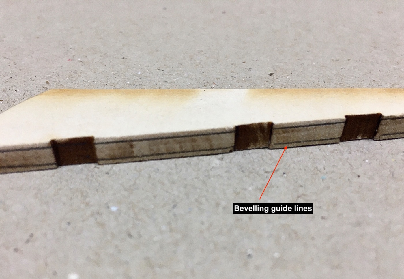
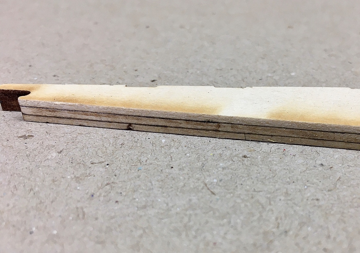
Throughout the building journey , as a principal, I followed the instruction booklet. However at various stages there comes a step where one must use common sense. You may skip some steps to come back later, do modifications or even inventions. But always think several steps ahead. I am sure you all understand what I am trying to say. As the kit was manufactured and plans were drawn and instruction booklet was written in 1994 ; it is inevitable to see several structural and color differences in the recent photos of the ship compared to that time. Even additions like two water tanks on both sides of the deck and a zodiac motor boat on top of ship's boat, beautiful Chasseur, can be seen in the pictures. To ignore or add these are the choice of the modeler I believe. For example I already have those waters tanks and zodiac boat in a workstation drawer for probable future addition to the model. OK ! Let's start the building now. The building starts with the preparation of center ( false) keel and the four pieces added to it. Those four pieces are stem, sternpost and two part keel. Oh ! there is also rudder which you may and can include for preparation in this stage. The center keel was one piece in my kit as opposed to some older kits in which it is 2 pieces to be glued together. So I was lucky at the start. First you draw the reference water line (RWL) taking measurements from the plan to both port and starboard sides. The lines must align with the ones on the bulkheads which you will see later. The bearding line , which sets the border between the cutout rabbet area and the untouched center keel area, is drawn. Then start cutting out the rabbet. As the thickness of the center keel is 3/16 inches and the thickness of the hull planks is 1/16 inches, after you finish cutting (and sanding of course) the rabbet there must be a 1/16 inches center keel thickness left where the four sternpost, stem and keel pieces be glued to. There is a gap at the junction of sternpost and aft keel which will be dealt with after those pieces are glued to center keel. After careful cutting and sanding the rabbet the first step is accomplished. During this process I used two 1/16 inch wood strips to control the amount of beveling frequently. As there remains a small area in the center keel where the four pieces are to be glued there must be some kind of strengthening procedure. Kit guide suggest wood dowels but I decided to use 1 mm diameter brass rods.After gluing the four pieces together I drilled the piece in 6 places. On horizontal plane and using 2 mm thick wood piece as a guide and using 1 mm diameter drill bit in order to approximately center the holes, I carefully opened 6 holes. As these areas will be painted small misalignments or retakes are not problematic at all. The receiving holes in the center keel planned to be drilled after the four-piece block is glued to it. Gluing is mainly yellow wood glue back-up with small amounts of liquid CA glue. After the gluing process holes in the center keel are easily opened with the same 1 mm dia drill bit through the already opened ones on the glued piece. Then the excess brass rods are cut off. Starboard side Port side The gap at the aft corner is shimmed with a piece of wood and sanded. Now the new keel border must be beveled at certain parts of it at certain amounts by using the plans for the locations. It is a reasonable choice to prepare the rudder beveling at this stage as its neighboring side with sternpost must be flush with it. Guiding lines for beveling amount are drawn to rudder sides after taking measurements from the plans . Rudder and sternpost are flush aligned. Next post will be preparation, dry fitting and installation of the bulkheads plus manufacture and installation of transom and counter blocks.


- 114 replies
-
- 9
-
-
- Pride of Baltimore II
- Model Shipways
- (and 1 more)
-
Thanks a lot Chris, The project is already finished and I posted the photos of the finished model in gallery under the same title as this blog’s. This will be a retrospective build blog.
- 114 replies
-
- 1
-
-
- Pride of Baltimore II
- Model Shipways
- (and 1 more)
-
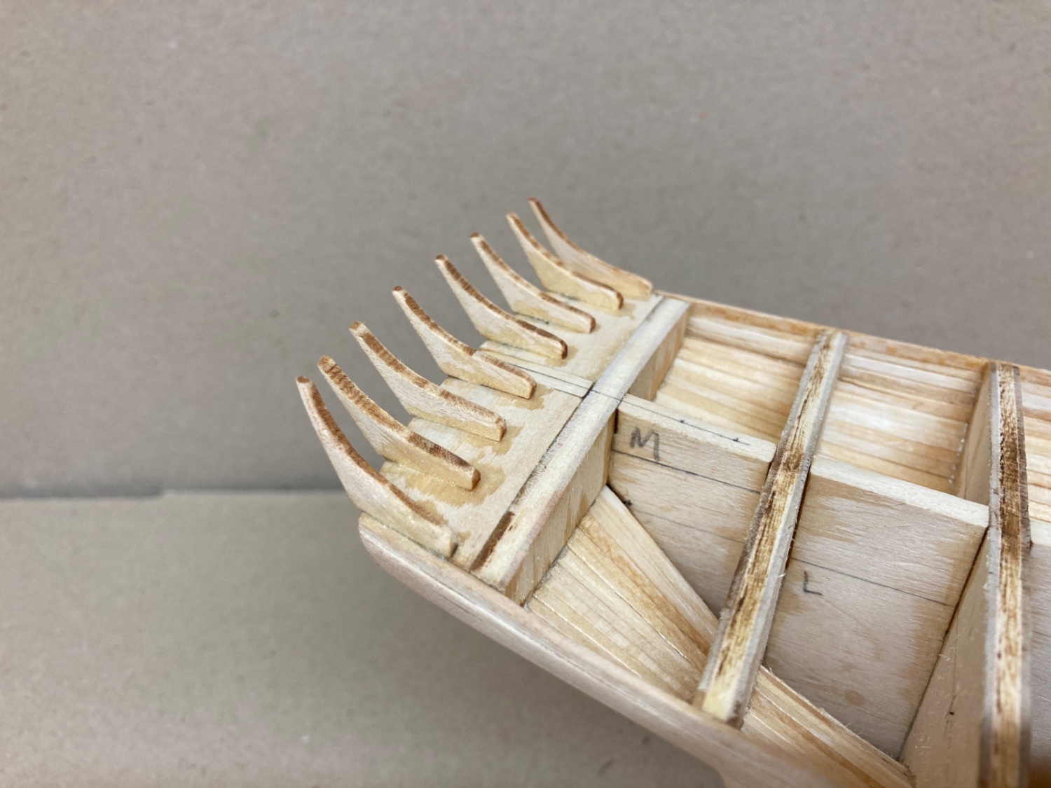
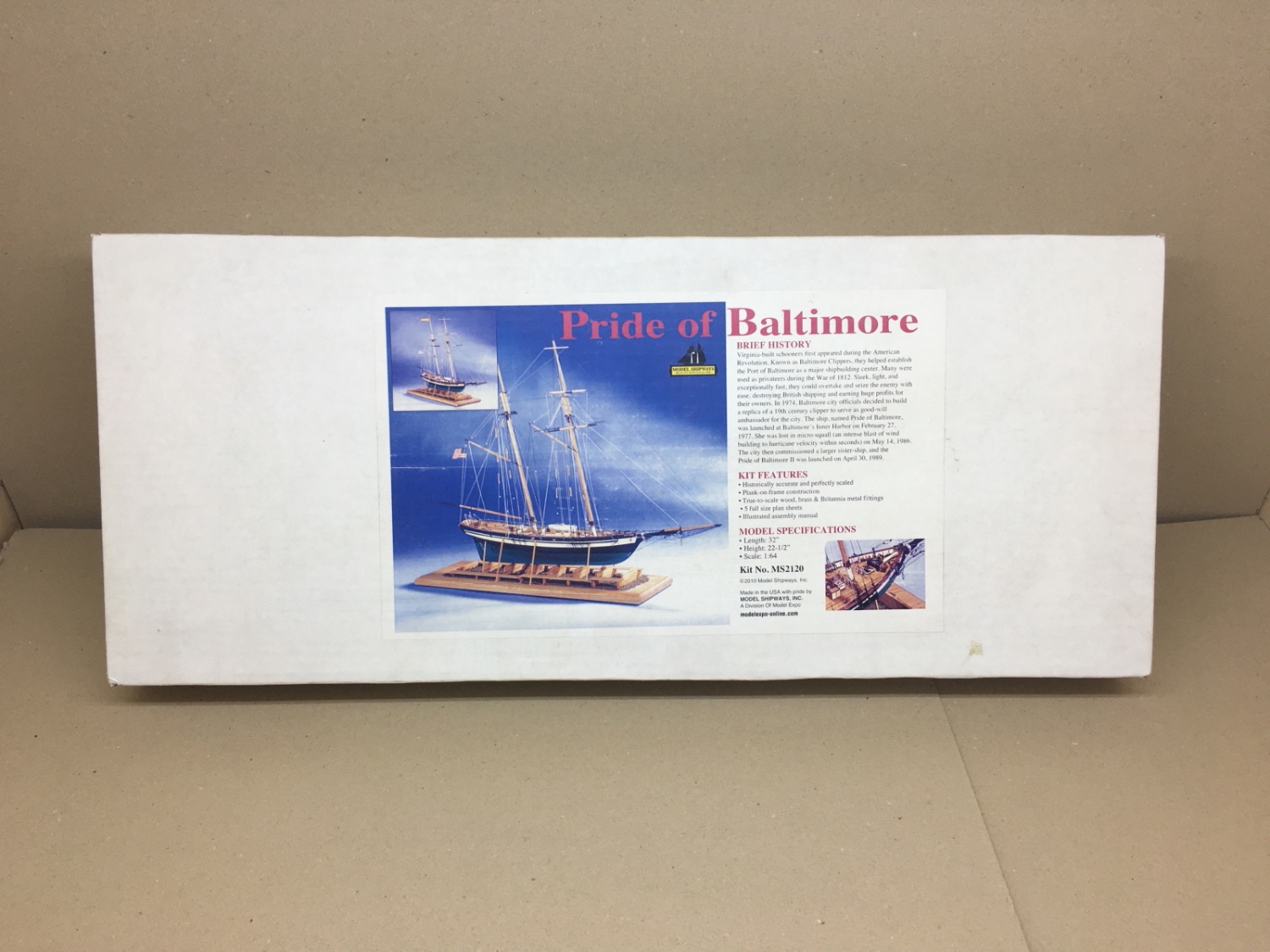
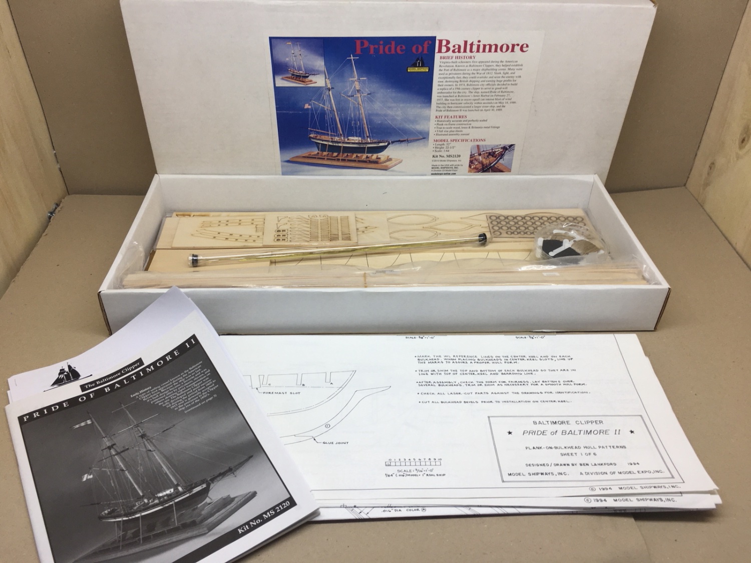
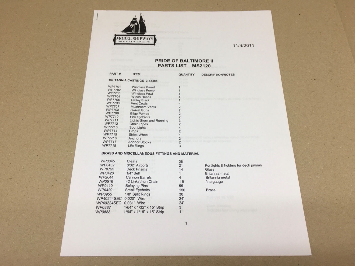
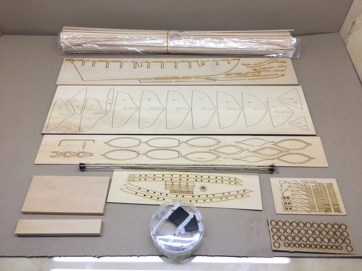
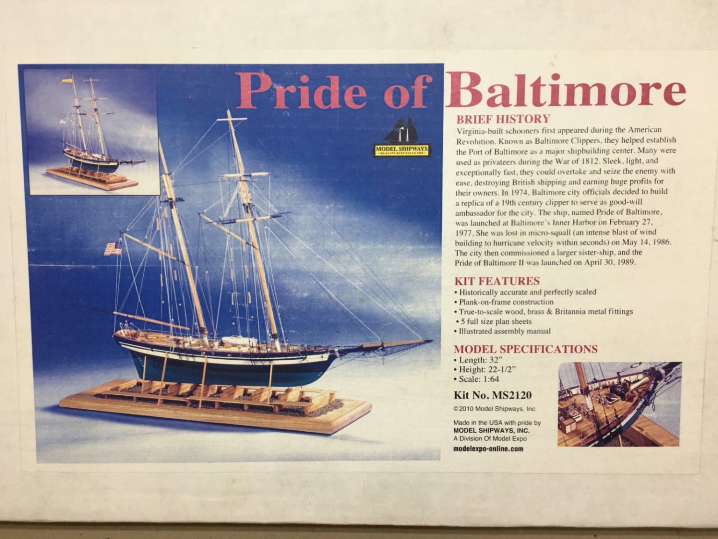
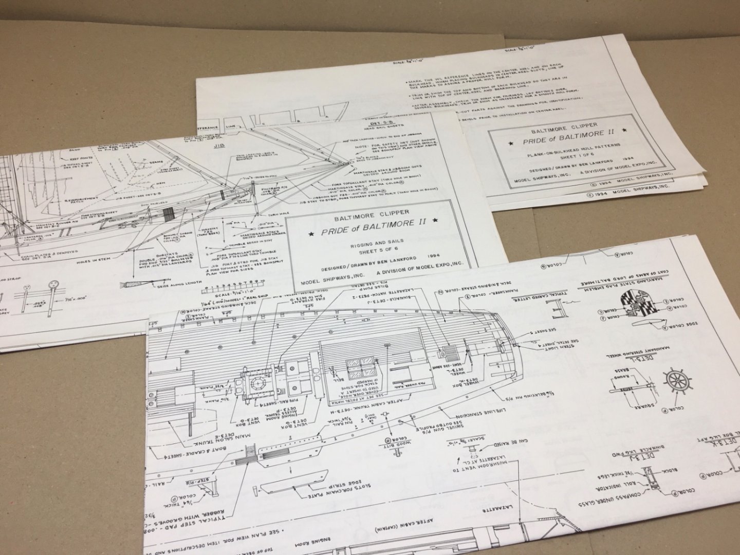
Hello Modeler Friends, This will be my first build blog posted in the forum. It will be a retrospective one as the model is already finished and finished photos are posted in the gallery under the same title as this blog's. I am a retired Otolaryngology surgeon and from Turkey as I have stated in my introduction post to the forum. Many of you probably wonder about the reason of the choice of this particular model. Here is the short story. In 2013 I was planning to start scale modeling after a gap of nearly three decades . At that time my son was living in Cliffside Park, NJ and a graduate student for his Phd studies in Rutgers Business School. Before visiting him I made some internet research and came across a hobby shop named Hobbymasters located in Red Bank, NJ. On one of his free days he took me to the shop. This kit was the only one on the shelf without a ready solid hull and I jumped at it at once. I was very happy with a yellow bag filled with a wooden ship model and some extras as paints, knife sets and brushes. I even asked my son to take a picture of me in front of the shop. I still keep the yellow plastic bag, shop's business card and even the receipt and credit card slip, all in the kit's box. After returning to home in Ankara, I studied the contents , especially the instruction booklet and the plans. I was a bit demoralized and overwhelmed by the number of parts and detailed plans . At that time I was building plastic model of Golden Hind by Airfix models and when compared to the kit I bought it was very easy. So after I completed Golden Hind, POB II stayed in the shelf until August 2020. Between 2013 and 2020 I build many models of wood horse drawn vehicles such as Civil War Coffee Wagon, Doctor's Buggy, Buckboard Wagon and Conestoga Wagon from Model Trailways, Stagecoach and Cavalry Wagon from Artesania Latina plus two ship models ( a Maine Lobster Boat and Bandirma ' Panderma ' by Turkmodel ) which are both local productions. This building sequence probably boosted my self-confidence and POB II travelled to workshop table from its resting place in the shelf on August 21st, 2020. Although it has been nearly 7 years after its purchase, the Modelexpo company quickly provided the missing and damaged parts without any questions asked . Here are contents of the kit. At the printing shop I got 3 copies of the plans printed and the owner provided me tiff pictures of them also. I used the copies of the plans throughout build and rarely consulted the original ones. I pinned one of the plans to the large cork panel on the wall in front of me in order to have a constant view. One of the plans was used for cutting out particular parts of it and keeping them on the worktable for to reach easily for measurements, calculations and transferring plans to wood. And one was kept for backup. Tiff pictures were uploaded to iPad and iPhone as well as to a computer for quick referring when I was away from the workshop. Before starting the build I researched a lot about the POB II build. There are a quite number of builds in the forum but many of them were unfortunately unfinished for various reasons. I am grateful to the modelers who finished them, mainly to Jdbondy, Karleop and David Lester. As I was accustomed to present my work, thanks to professional as a teaching professor of medicine as well as a practicing surgeon, I believe shared experiences are valuable whether successful or not. With your failed work, at least you can warn others and alert them about what not to do !. This is the main reason I am starting this blog. There will be a lot steps you will disagree and probably are wrong. But keeping in mind the phrase ' there are many ways to skin a cat' and as I did finished the model , I hope my journey will be helpful to the future builders of this beautiful model. I will try to post daily and preparation of the false keel, stem, sternpost and rudder will be on the next one. The link to the photos of the finished model can be viewed at gallery https://modelshipworld.com/gallery/album/2633-pride-of-baltimore-ii-by-halituzun-model-shipways-164/ Index of the post topics (with page number/post number/topic subject/s). This index is in the order of the real build time (95 %). Topics are linked directly to their post. Clicking the underlined words opens the post page. 1/1 Introduction 1/4 False keel, keel, sternpost, stem and rudder 1/7 Bulkheads, stern blocks 1/10 Bulkhead and stern block beveling First hull planks Wale planks 1/13 Zone A hull planking 1/14 Zone B hull planking 1/15 Zone D hull planking 1/16 Zone C hull planking 1/17 Counter planking Completed hull planking 1/21 Hull sanding 1/22 Planksheers, Stern knees 1/23 Transom planking Hawse timbers 1/24 Coamings Preparation for deck planking 1/25 Painting of plank sheers, stern knees and coamings 1/26 Deck planking Choosing stain color for deck planks 1/29 Bulwark construction 1/30 Staining deck planks 2/32 Pintle and gudgeon brackets 2/33 Hull, deck and bulwarks sanding sealer 2/35 Final painting of sheer planks, stern knees, transom inboard and coamings Bulwark painting 2/36 Drilling holes on the deck and bulwarks inboards Construction of bulwarks inboard structures ( cavels, mooring chocks, wood cleats) 2/37 Fore deck second layer planking Matt clear coat for deck Bulwark inboard structures installation Ship's name at bow 2/40 Fancy piece, Fashion piece, Transom mouldings 2/41 Bulwark installation Drilling Hawse pipe holes Inboard and outboard stringers 2/42 Propeller, support brackets, shaft and shaft log 2/43 Transom lettering 2/44 Primer paint coats for hull 2/45 Load Water Line (LWL) drawing 2/46 Hull painting below LWL (green) 2/47 Hull painting, yellow and black Transom and depth gauge lettering Gloss coat for hull 2/50 Main rail production and installation 2/51 Main salon production 2/52 After Cabin production 2/53 Engine room top production 2/54 Crew berthing/galley access top production Fire hyrant, hose and nozzle production 2/55 Hatch, wheel, wheel box and binnacle production 2/58 Ventilation boxes and deck lockers production 2/59 Windlass 2/60 Fife rails, pin rails 3/66 Bow fairlead, Fore deck steel hatch, Pin and cleat platform at bow Channel platforms, Anchors, Catheads, Gunport lids, Steps, Wood bits, Swivel Guns,Propeller system, Bilge pump hose and nozzle productions 3/67 Building-ways 3/69 Ship's boat 3/70 Cannons 3/71 Life rings 3/72 Mast and spar construction and painting 3/73 Bowsprit construction and painting 3/74 Blocks, deadeyes, metal thimbles, metal turnbuckles, lower yard sling baggy wrinkles, preparation and productions 3/75 Final satin coats of the hull Installation of the all finished deck structures except the the ones around the mast insertion holes. 3/78 Rigging preparation and plan Structures related to rigging on masts and spars Rigging lines and blocks preparation and bagging them with tags 3/79 Bowsprit Rigging 3/80 Bowsprit safety netting 3/83 Sail preparation 3/87 Fore Topgallant Sail 3/88 Fore Topsail 3/89 Main Gaff Topsail 3/90 Main Sail 4/91 Fore Sail 4/94 Installation of the fore mast yards 4/95 Installation of the masts to the deck 4/96 Running rigging of the lines belaying at the bases of the masts Running rigging of main boom at aft deck 4/97 Forestay Sail, Jib and Jib Topsail 4/98 Rigging II 4/99 Coiled ropes 4/105 Shrouds, Ratlines, Topmast Stays and Running lights 4/107 Weathering of sails and coiled ropes 4/108 Life lines, Swivel Guns, Shroud cleats and Main Stay Hauling Tackles 4/110 Flags, preparation and installation


- 114 replies
-
- 9
-
-
- Pride of Baltimore II
- Model Shipways
- (and 1 more)
-
Is there a limit of the number of photos per post ?
-
Thanks a lot admins Chris and Chuck. I have about a week or ten days left on my current project which is Pride of Baltimore II by Modelexpo Model Shipways. Best regards
-
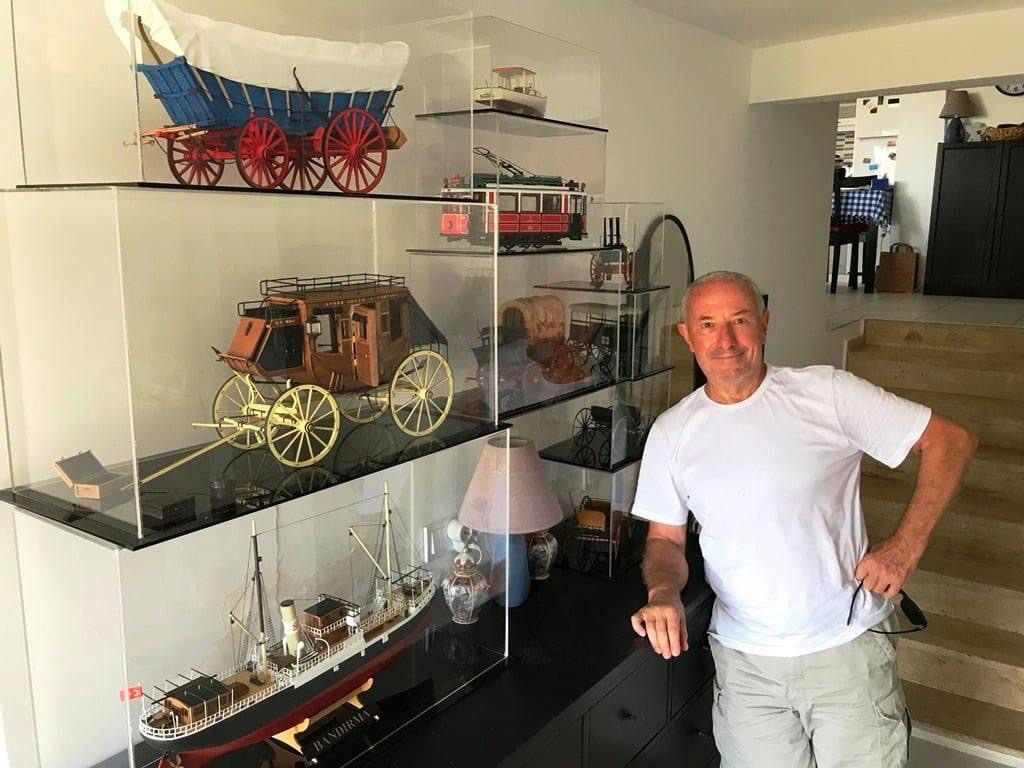
Hello friends, I am a retired Otolaryngology Surgeon since 2017 and residing in Bodrum, Turkey. Bodrum locateted in southwest part of Turkey , a worldwide well known holiday resort and I live here for the very best part of the year. January and February are spent in Ankara, the capital, as winter conditions need it. I am 70 years old, married and have a son of 38 years. Although my history of scale modelling dates back to early 80’s , I was able to concentrate on the hobby only for the last 6 or 7 years due to very busy professional life. Actually I am not a recent member and a member since 2018. Sorry for the late introduction. I am adding a photo of mine taken in front of some finished works of mine, taken in Bodrum residence. I am sorry if there are any mistakes in my post as English is not my native language. Best regards to all
- 12 replies
-
- 15
-
-
-
uploading pictures
halituzun replied to David56's topic in Using the MSW forum - **NO MODELING CONTENT IN THIS SUB-FORUM**
Hello, Is there a size limitation of uploaded photos in terms of kb or mb besides pixel size of 1200x1600 ? If you posting a JPEG image there is a quality option , which effects its size kb or mb , when saving it in the final step when you are resizing it ? Thanks…. -
Hello Sir, Is it possible to start a retrospective build log of a model already finished ? If so, is it allowed to post the pictıres of it in the ‘finished builds’ gallery at the same time ? Thanks a lot. Best regards.