

Don9of11
-
Posts
718 -
Joined
-
Last visited
Reputation Activity
-

 Don9of11 reacted to Chuck in Queen Anne Style Royal Barge by Chuck - FINISHED - Syren Ship Model Company - 1:24
Just wanted to give all of you a more detailed look at what the new Queen Anne Style Royal Barge project will look like. You are looking at the preliminary draft for the plans. A PDF is below for a more detailed look. I am not worried about theft because there are no laser cut parts or templates shown on this sheet. I removed those. As the project and prototype gets built, more details will be added to aid the builder. Including those parts which were removed as theft prevention. This is why it is so important to have someone else build the project before its released. They will give me feedback on what additional views and parts would be helpful to include on the plan sheets. And when its completed they should be quite detailed....even though I think what is shown is probably already detailed enough for most folks.
As you can see. This sheet includes many views of the model at various stages of its construction so those elements can be more easily seen. This includes a planking expansion on the bottom of the sheet.
With the plans fully developed all that is left to do is build the prototypes....two of them. Make adjustments...Update and embellish the plans where needed...write the instructions.....and then start on packaging and production. This will include making all laser cut parts, cast decorations...and wood decorations.
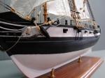
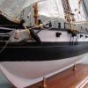
The model will be nearly 19" long and 3 1/2" wide at 1/2" scale. It will very closely resemble the contemporary model pictured.
Let me know if you have any questions.
Chuck
queenannebargeplanmsw.pdf
-
 Don9of11 got a reaction from Canute in HMS Bellerophon 1786 by AON – scale 1:64 – 74-gun 3rd Rate Man of War - Arrogant-Class
Nice work Alan! I always learn something when I come to see your progress. Have you tried using a 4H or 6H pencil? I have found that these leads hold their sharpness a little longer than the standard 2H.
-
 Don9of11 got a reaction from mtaylor in HMS Bellerophon 1786 by AON – scale 1:64 – 74-gun 3rd Rate Man of War - Arrogant-Class
Nice work Alan! I always learn something when I come to see your progress. Have you tried using a 4H or 6H pencil? I have found that these leads hold their sharpness a little longer than the standard 2H.
-
Don9of11 reacted to AON in HMS Bellerophon 1786 by AON – scale 1:64 – 74-gun 3rd Rate Man of War - Arrogant-Class
June 11 2016
I cut the frame steps into the port side of the aft deadwood and installed two more sections of the rising wood... and yes those are the two upper most transom pieces dry fitted into place.
The Wing Transom and the Filler Transom.
I intend to cut the other transom pieces but will not be fixing them in place permanently until I get the Stem Post (at the pointy end as my darling wife refers to it) in place.
-
Don9of11 reacted to AON in HMS Bellerophon 1786 by AON – scale 1:64 – 74-gun 3rd Rate Man of War - Arrogant-Class
Worked on the aft frame steps in the deadwood and stern post.
Finished one side with an error realised at the end... I went too high up on the stern post.
(I thought I was being so careful)
Now I must sleep on how to fix it... I have a couple ideas in mind.
-
Don9of11 reacted to AON in HMS Bellerophon 1786 by AON – scale 1:64 – 74-gun 3rd Rate Man of War - Arrogant-Class
June 5 2016
I marked off the various transom steps into the stern post. Sawed down to the reasonably proper depth (3/32" or 6") then made a number of cuts between, chiselled out the pieces and filed flat and square.
I then cut out a template of the stern frames in side view and laid it over the dry assembly of the deadwood and stern post. Some guide pencil marks were made on the wood but I did trace the wood assembly onto the template so I can properly lay it over again and trace the steps onto the wood.
The taper was marked onto the deadwood and the stern post was sanded to the line while the deadwood assembly was sanded down to just outside the line.
Presently all is glued together to the keel and set to dry.
Once dry I will finish the sanding and trace the step locations onto both sides of the deadwood then cut this in.
-
Don9of11 reacted to AON in HMS Bellerophon 1786 by AON – scale 1:64 – 74-gun 3rd Rate Man of War - Arrogant-Class
MAY 8 2016 (Mother's Day)
Worked on the aft deadwood today and it took a number of tries resulting in numerous pieces added to the scrap bin.
As always, after cutting and sanding I checked the fit on my light table (light box). I found myself chasing my tail a few times where I ended up creating the scrap.
Eventually I ran out of patterns and had my master from which I traced the pattern onto a piece of translucent graph paper and then transferred the pattern onto the piece of boxwood. I used a 6H (hard) pencil to get a nice crisp sharp line.
Eventually the pieces fit well enough and were glued together. I put a few dabs of wood glue onto both pieces, spread it with a small plastic tool I have for the job and then assemble the pieces. This takes a minute or two so the glue is getting tacky by then. The two pieces get rubbed together in a rotation to spread the glue between them further, working any excess out the sides and then they are aligned properly and held finger tight until it begins to set. This usually takes about another 3 minutes.
I ended up with a section of the aft Deadwood done. The Rising Wood section between the main Keel and this assembly is not done, and the Knee piece is not glued on as yet as the top portion of it needs some shaping and fitting.
I have purposely not cut the aft vertical end yet. After I have the Knee and Rising Wood added I will sand the back facing the stern post to the proper angle and add them all to the keel permanently. But I will need to clean them up and mark the framing heel step notches to both sides first.
I find it difficult to not jump ahead and think about the assembly of other parts. There is so much left to do here at this stage. I should be concentrating on this stage and what comes next. Seeing as how I've learnt to slow down and do one piece at a time, I am sure the focusing of my concentration will also come in time.
-
Don9of11 reacted to AON in HMS Bellerophon 1786 by AON – scale 1:64 – 74-gun 3rd Rate Man of War - Arrogant-Class
Sunday 01 May 2016
Made the Main Stern Post and Inner Stern Post today.
Cut out the two patterns.
Cut a strip of Castello Boxwood to 1/2" thick, Milled to 0.365" (23.36" at 1:64)
Per the build contract the stem post is 23" square at the head and begins to taper from the underside of the deck transom to be 12-1/2" at the main keel.
You can see I incorrectly identified the deck transom, highlighted them all in yellow and re-identified them correctly.
Applied rubber cement to the wood and then to the back side of the templates. Let it dry to "tacky" and then applied the template to the wood. pressed them down and let them dry.
Cut out the two pieces on the scroll saw about 1/16" outside of the line then sand down flush to the line on the table top disc sander portion of my combination belt/disc sander. I double checked the table was square to the disc first!
Glued the two pieces together with yellow wood glue, pressed together and let it dry.
Marked off the transom positions from the templates to the end faces.
Marked of the centre lines on the end faces
Marked off the taper on the end faces
Marked off the rabbet line at the head and foot
Marked off the tenon, cut and filed down to a snug dry fit into the main keel mortise.
There should be multiple tenons but I simplified it to be a single tenon into the single mortise made earlier in the keel.
Peeled off the templates
Checked it to the plan.... perfect angle.
Still needs to be tapered and recessed steps cut for the Transoms, but I think I will do the Deadwood first as it tapers with the stern post assembly plus it needs to be cut for the rabbet.
The contract also calls for a "a square plate of iron of the knee kind" meaning a L shape, 5/8" thick x 4-3/4" wide with the vertical leg 3'-6" (and 3 x 7/8 bolts) and the horizontal 5'-6" long (with 4 x 7/8" bolts).
I find it odd that they call up an iron plate below the waterline... Unless it is the newer mixed alloy... this makes sense.
Then again it is recessed into the wood so it would be coated with tar before the copper sheathing was applied.
Would anyone know for sure?
That is enough for today.
Thank you for following.
-
Don9of11 reacted to AON in HMS Bellerophon 1786 by AON – scale 1:64 – 74-gun 3rd Rate Man of War - Arrogant-Class
Sunday 24 Apr 2016
Lesson learnt; opportunity seized.
All staples installed.
All staple blackening flaked.
Likely due to being too long in the solution and possibly too strong a solution.
The LOS blackening process is an oxidation layer on the surface of the material. If the layer gets too thick it can flake or peel/pop off in handling.
I figured I would simply install them now and re-blacken them in place later... but when cleaning them up the strangest thing happened. They were left with a hint of patina suggesting ageing... and I like it. All of a sudden the copper stands out against the wood and it looks like the real staples I posted earlier
Let us wait and see if the feeling sticks with me.
Next I tackle the stern post(s).
Installing staples - prior to cleaning up.
After cleaning up
-
Don9of11 got a reaction from mtaylor in HMS Bellerophon 1786 by AON – scale 1:64 – 74-gun 3rd Rate Man of War - Arrogant-Class
Alan, see if your camera has a macro mode as this will allow you to zoom up closers and get clear pictures.
-
Don9of11 got a reaction from Canute in HMS Bellerophon 1786 by AON – scale 1:64 – 74-gun 3rd Rate Man of War - Arrogant-Class
Alan, see if your camera has a macro mode as this will allow you to zoom up closers and get clear pictures.
-
Don9of11 reacted to AON in HMS Bellerophon 1786 by AON – scale 1:64 – 74-gun 3rd Rate Man of War - Arrogant-Class
Tuesday evening 12 April 2016
Made a couple "anvils" using a 1/4" hex nut. I had a few sides to work with!
Applied painters tape to be able to draw a straight line from side to side to mark the cut points.
Marked off 9" width of staple.
Used my dremel and a cutting wheel to notch the nut sides.
Fitted a staple to test... it took a couple extra nicks to get the depth correct to hold the staple properly.
Set it up in my vise and gave it a "wack"... more of a gentle tap or two.
They look darn good to me.
I apologize for the poor pics.
My little Cannon Power Plus A520 doesn't seem to focus well on the tiny stuff
(or is it me???)
Environment Canada announced this morning that winter is officially over for southern Ontario.
No more snow... if you can believe a weatherman.
Should be blackening this weekend.
-
Don9of11 reacted to AON in HMS Bellerophon 1786 by AON – scale 1:64 – 74-gun 3rd Rate Man of War - Arrogant-Class
Sunday 10 April 2016
I Just completed 250 staples. By count mentioned earlier I deduced I require 240, so there are 10 extra.
I found an quicker way to make them after the first 20 or so, I eliminated the wood form and just used the clamp as it ended up being the perfect width!
Drilled all the holes in the false and main keel today. Ended up drilling 4 more staple locations due to alignments with nails and bolts and scarph joints. So that leaves 6 extra.
So in the photo below you will see what 250 each x 9" long (0.1406" = 0.357cm) copper staples look like and see the keels peppered with holes.
I partially inserted 3 staples for effect. They are not yet blackened. Still too cold for me to do my first ever blackening in the garage and I dare not stink up the house or the love of my life will have something to say about it.
I also decided only two of the offending keel scarph joint bolts absolutely needed correcting and so took care of those. Tried to drill out the one side about 1/8" deep. That did not work as the monofilament line will not allow the bit to bite (too slippery). Ended up gouging out with a flat bottomed bit and filing in the hole with glue and fine powder sawdust. Now I can live with it. Thank goodness I am striving for realism and not perfection! (I haven't the talent for perfection)
-
Don9of11 reacted to Mark P in Gun Port Framing
Hi Thistle;
The gun-port cills and lintels (also called cills, actually: upper cills) were aligned with the curvature (sheer) of the deck, maintaining a constant distance from the deck at the side of the vessel. The sides of the ports are at right-angles to the keel, parallel to the station lines (there are some exceptions, but this is by far the general rule)
This means that the gun-ports are not square, except for a few right amidships, but are actually a parallelogram shape, with the angles increasing towards the stern and bow.
To answer your question about guns moving: when they were not being used the guns were stowed by raising the muzzle to its maximum and hauling the gun tight to the ship's side. The muzzle then fitted into a curving recess cut into the back of the upper cill. The gun-tackles were lashed up taut, and an additional rope lashed around the muzzle and made fast to an eye-bolt in the side above the port.
Hope this helps.
All the best,
Mark P
-
Don9of11 reacted to AON in HMS Bellerophon 1786 by AON – scale 1:64 – 74-gun 3rd Rate Man of War - Arrogant-Class
Couldn't do anything through the week and not much progress today.
Made new keel pieces this afternoon.
I am very happy with these and will hopefully glue the paper on tomorrow and might get the sections together.
-
 Don9of11 got a reaction from Capt.Rick in Brig USS Enterprise 1799 info gathering
When I was building my model of the Enterprise which was the kit by Constructo (#80822) I came across a couple publications in my research. The first was an article that appeared in the winter 1999 issue of the Journal Of The War Of 1812 by Michael Bosworth. I don't think this paper is in print anymore so if you would like a copy let me know.
The second, was an article I found on a website I believe was called The Ancient Mariner, again I don't think this paper is available anymore either.
And thirdly, is a book you can download from Google called "The Lucky Little Enterprise" and Her Successors In the United States Navy 1776-1900 by Fredrick Stanhope Hill. This book is also available through the Internet Archeive https://archive.org/details/luckylittleenter00hilliala.
I have some photos of my build here
and here
http://howefamily.com/zellars_progress_photos/zellars.asp
-
 Don9of11 got a reaction from AON in HMS Bellerophon 1786 by AON – scale 1:64 – 74-gun 3rd Rate Man of War - Arrogant-Class
These are awesome drawings Alan, very impressive.
-
Don9of11 got a reaction from mtaylor in HMS Bellerophon 1786 by AON – scale 1:64 – 74-gun 3rd Rate Man of War - Arrogant-Class
These are awesome drawings Alan, very impressive.
-
Don9of11 reacted to AON in HMS Bellerophon 1786 by AON – scale 1:64 – 74-gun 3rd Rate Man of War - Arrogant-Class
PDF Templates
Print to size indicated in title and on image
The first file as a 36" x 60" PDF sheet is a 4.5Mb file
I tried compressing it but cannot get it below 3.5Mb which is still tool large for uploading
So I've uploaded a JPG file.
If anyone prefers the PDF please PM me with your personal e-mail address and I'll send it to you.
You still need to purchase the original HMS Elephant documents from NMM
image J2930 (lines), J2934 (framing) , J2938 (decks) and the Bellerophon build contract ADT009 for details.
EDITED: note the correction to be made to the station labels near the deadflat in this image below (Alan 16 AUG 2021)
(2) 36x48 STEM_STERN POST + KEEL.pdf
(3) 36x60 Stn H-AFT to Stemhead sh 1 of 2.pdf
(4) 36x60 Stn H-AFT to Stemhead sh 2 of 2.pdf
(5) 36x60 Stn 2-AFT to G-FWD sh 1 of 2.pdf
(6) 36x48 Stn 2-AFT to G-FWD sh 2 of 2.pdf
(7) 36x60 Stn 3 to 17 sh 1 of 2.pdf
(8) 36x60 Stn 3 to 17 sh 2 of 2.pdf
(9) 36x60 Stn 18 to STERN sh 1 of 3.pdf
(10) 36x60 Stn 18 to STERN sh 2 of 3.pdf
(11) 24X36 Stn 18 to Stern sh 3 of 3.pdf
-
Don9of11 reacted to PAnderson in TurboCAD PC vs Mac
The speed of your computer won't as great a deciding factor as will the amount of memory you have. And possibly your graphics card.
Paul
-
Don9of11 got a reaction from AON in HMS Bellerophon 1786 by AON – scale 1:64 – 74-gun 3rd Rate Man of War - Arrogant-Class
Excellent work Alan. Your model will be an inspiration to others. I especially like your development of the stern, beautifully done.
-
Don9of11 got a reaction from mtaylor in HMS Bellerophon 1786 by AON – scale 1:64 – 74-gun 3rd Rate Man of War - Arrogant-Class
Excellent work Alan. Your model will be an inspiration to others. I especially like your development of the stern, beautifully done.
-
Don9of11 reacted to AON in HMS Bellerophon 1786 by AON – scale 1:64 – 74-gun 3rd Rate Man of War - Arrogant-Class
The hull model is as complete as I need to go with her.
Now I finish my templates, and will finally be on my way with the build.
Why does the last 5% take 25% of the time?
-
Don9of11 reacted to AON in HMS Bellerophon 1786 by AON – scale 1:64 – 74-gun 3rd Rate Man of War - Arrogant-Class
I said I wouldn't but it was such a nightmare to do this last little bit I had to post it
It is not completed yet but the worst is over
(thanks to my Irish/Scottish/French/Portuguese stubbornness)
I present the (uncompleted as yet) "stern"!
-
Don9of11 reacted to AON in HMS Bellerophon 1786 by AON – scale 1:64 – 74-gun 3rd Rate Man of War - Arrogant-Class
Fast approaching two years and little to show.
I am about where I was in my last model when my computer died and I lost my privilege to using SolidWorks.
I've completed (for the most part) up to frame 28. Need to add the Gunports.
The last couple quarterdeck gunports are drawn narrower than actual as the frames are bent and if I cut out the full gunport I'd loose the frame cutting template detail I need.
About to complete the stern.
Below is a snip of my progress and what is left to do!
Being an old draughtsman I admit to not being able to see my own mistakes and so relied on my working associates to check my work after I had thought I'd thoroughly reviewed it. I miss my checkers but alas they wouldn't know what to look for in these models and drawings. The further away from the Dead Flat I get the more my errors pop up. Caught most (I believe) but will have to clear my head and give it a few final reviews when I am done.
I have not drawn in the shifting, bent and very special frames shapes as I will be working very closely with a clean print of the original framing draught to pick up those details. My drawings are to get the basic molded shapes for cutting.
Will post again when I am done... or I stumble again.
BTW... my "Waldo" frames proper name still eludes me and I continue to look.