CCClarke
-
Posts
25 -
Joined
-
Last visited
Content Type
Profiles
Forums
Gallery
Events
Everything posted by CCClarke
-

Starting in Rhino 8
CCClarke replied to GioMun's topic in CAD and 3D Modelling/Drafting Plans with Software
I must have been lucky. The design engineers using SolidWorks where we worked were very good at what they did, but were not artistic. Their renders for presentation packages were basically different colors to identify different parts within an assembly. These types of graphics are common, and we wanted to stand out from our competitors. Once I got my CG footing, I converted our inhouse models, (or used technical drawings to model when conversion was too time-consuming to meet a deadline) into photo-realistic renders. The reaction of the customers to our enhanced presentations was immediate and positive, which gave me a niche that turned a collateral duty into a full-time gig. Everybody won. After that, I started adding graphics to training and documentation packages. This was especially helpful when the hardware was very small or might require a "God's eye" view from a distance. Occasionally, a customer would call with a specific request for one of their presentations, and that became another capability we capitalized on. On more than one occasion, other companies would ask for some of my models, or request me to travel to their facility to collaborate on a shared contract with their graphics people. I never ran out of work. Even after transferring to the East coast to another part of the company, my old management asked to "borrow" me. Those requests were flatly refused, since my other skills in high-reliability, precision assembly and QA were more valuable and we were always short-handed. I still did graphics work for the Director when an important presentation was looming. It was very enjoyable having acquired a lot of useful training and certifications during my career, many of which I apply to ship modeling while retired. -
Starting in Rhino 8
CCClarke replied to GioMun's topic in CAD and 3D Modelling/Drafting Plans with Software
I have a feeling you're going to amaze me very soon Giorgio! One common theme I read in posts throughout the modeling forums I visit are from people wishing they could model and others who tried and quit in frustration. I was fortunate to attend a top-notch school that focused on modeling and animation with some of the best teachers from the television and film industry to share their experience. I had been modeling for almost a year and my workflow, (really, my best-guest flow) was full of bad habits I had to unlearn immediately. Every student there paid big bucks and all were motivated to get jobs in the industry. I was by far, the oldest student in the school and a subject of much curiosity. The majority of the students were teenagers or in their early twenties. (I was 48, and my training was paid for by my company to help us make better presentations for high-dollar contract bids.) We started with about 31 students the first day. Two weeks later, there were 15. A month later a few more had dropped. I asked the Director of the school if this was normal and he said unfortunately, it was. Every one of those students under-estimated the amount of work was involved to become proficient, both during and after school. The homework load was pretty heavy and modeling things that take me minutes now, took hours then. Living in a hotel without any distractions, I studied at least twelve hours a day. On weekends, even more. Our teacher emphasized the mindset I mentioned before. Even though I was a dedicated student from previous experiences, I still hit a few obstacles and documented them to ask questions in class. I still have that notebook and read it once a year. This is another reason I emphasize writing everything down when starting out. (I still do it now!) A few simple things to model, (especially with digital calipers or a tape measure for large objects) are: A Pair of Dice. -A simple cube with cylinders arranged to form the "dots" subtracted from each side. (The number of dots on opposing sides should equal seven.) A Desk: Entirely composed of square objects stretched and aligned to fit. Your Kitchen: The cabinets are usually nothing more than thin squares and rectangles. The walls can be made from larger rectangles positioned accordingly or a single, six-sided box (reverse the polygons and remove the top and two outer polygons to create a diorama effect with no wall thickness) as another method. A Flying Saucer! Create the exterior profile by making a single spline or group of points turned into a single polygon for the profile, then Spin, Revolve, or Lathe (a very common tool with different names in each app) with the flat side that makes up the middle on the Y axis @ the zero position. The more sides you Spin, Revolve, or Lathe, the smoother your UFO will be. The more points in the profile, the higher the polygon count. A Wine Glass or Goblet: Same workflow as the UFO. Being able to use your tools to create these shapes is applicable when building a ship model. If something I've written doesn't make sense or you need example screen shots to help illustrate my points, feel free to PM me and I'll describe in more detail how I do it. Just tell me what program you're using, (Rhino?) and I'll try to get the tool names right for your application. Chi non risica non rosica! CC -
Starting in Rhino 8
CCClarke replied to GioMun's topic in CAD and 3D Modelling/Drafting Plans with Software
Keep at it Giorgio! There's lot of good advice in this thread. As a beginning modeler, (even when you understand all of the basic tools) one of the hardest things to learn is where to begin. For me, that was the hardest part, and it was very intimidating. Like karate, you can learn to punch and kick, but combining variations of those moves is what gives you the confidence and ability to prevail in a real fight. Modeling is very similar. Too many tutorials focus on tools without showing how to combine them to create and modify more complex shapes. Combining tools to make what you want is called workflow, and it comes to you over time and many, many dead ends. The other quality needed to become proficient is the correct mindset. Modeling isn't easy or everybody would be doing it. The AI generative 3D modeling programs being shown online are a poor substitute for real-world modeling skills. Once you learn to model, you have a skill that can never be taken away from you. Nobody learns anything without making mistakes. Perseverance is a big part of learning the craft. I've had times where I couldn't make a particular tool perform the way I thought it was supposed to. Every tool has rules that must be learned and some of those rules aren't well-documented - if at all. I spent three eight-hour days once, using the same tool over and over to learn what made it unable to continue, while the program gave me error messages that made no sense. Every time I got it to work, I wrote down what made it fail. I was surprised how many conditions could cause this and submitted a post online explaining how I made it work. The many replies of thanks were astounding! Many modelers had given up on that tool, limiting their ability to progress. I had to break through that wall by chipping away at it, little by little and documenting everything. The things I learned went into my workflow, and contributed to my ability to inspect the mesh for irregularities when using other tools, that I still use today. I don't even think about it anymore, I just use those skills automatically the second something doesn't work and quickly solve the problem. The learning never ends, which is another facet of modeling I enjoy - problem-solving, which really sums up what 3D modeling is, and I've been doing it almost daily for twenty years. A lot of what you're starting out with in your examples is basic spline modeling to create hull curvatures. A spline is nothing more than a curved line defined by how many points are in it. Those points can be patched, (automatically or manually) to create polygons which becomes a "skin" as more polygons are added to the mesh. Every model is composed of points, edges, and polygons. Each modeling program manipulates them in similar ways using different tool names. Personally, I would recommend modeling simple things around your house. A salt-shaker can be made with a couple of basic modeling tools. Those same tools can make a cannon or pedestal. Be realistic about your expectations to keep your progress moving forward - even if in tiny increments. A ship's hull is more complex and can lead to great frustration or worse, giving up. Start simple, (like making a table or the afore-mentioned salt shaker) to get the basics of creating and moving and aligning shapes before progressing to more complex shapes. You will be surprised how quickly you begin to create a workflow that gives fast results. One of the first (physical tools) I invested in to help my modeling of simple objects was a set of inexpensive digital calipers. It helped me to create the everyday things around me more accurately and proportionately. Success builds enthusiasm, and enthusiasm is contagious! Time how long it takes to make a simple object if you're following a tutorial. Repeat the tutorial the next day. The day after that, build the same object without the tutorial, until you have the workflow memorized. Notice how fast you build it compared to the first time. My modeling speed doubled every three months once I had the basics figured out. Some of the tutorials took me hours to complete at first. Using the method I described allowed me to do in minutes what had taken hours in a very short period of time. Timed modeling is an excellent way to measure your progress and keep you motivated. When you have the basic tools memorized, (and more importantly, how to use them in combinations) move into spline modeling, which is a different style of modeling. Like math, there are many ways to get the correct answer when modeling. The best way is the one that works for you in the least amount of time achieving the shape you need. Maintaining the correct mindset is the one tool not included with your software that ultimately determines your success. Everybody who invests the time to create beautiful models can relate to this philosophy. All of them started knowing nothing. I look forward to seeing your progress, even if it isn't ship-related. CC -
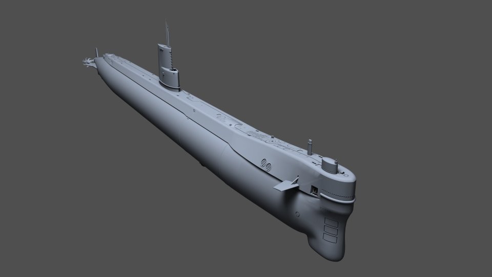
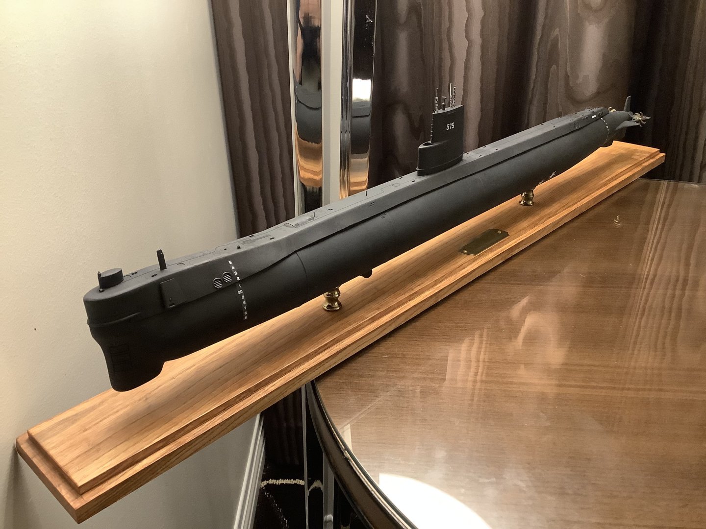
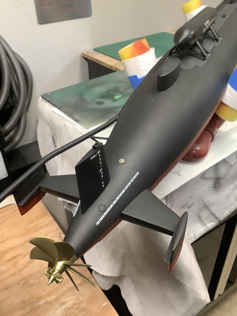
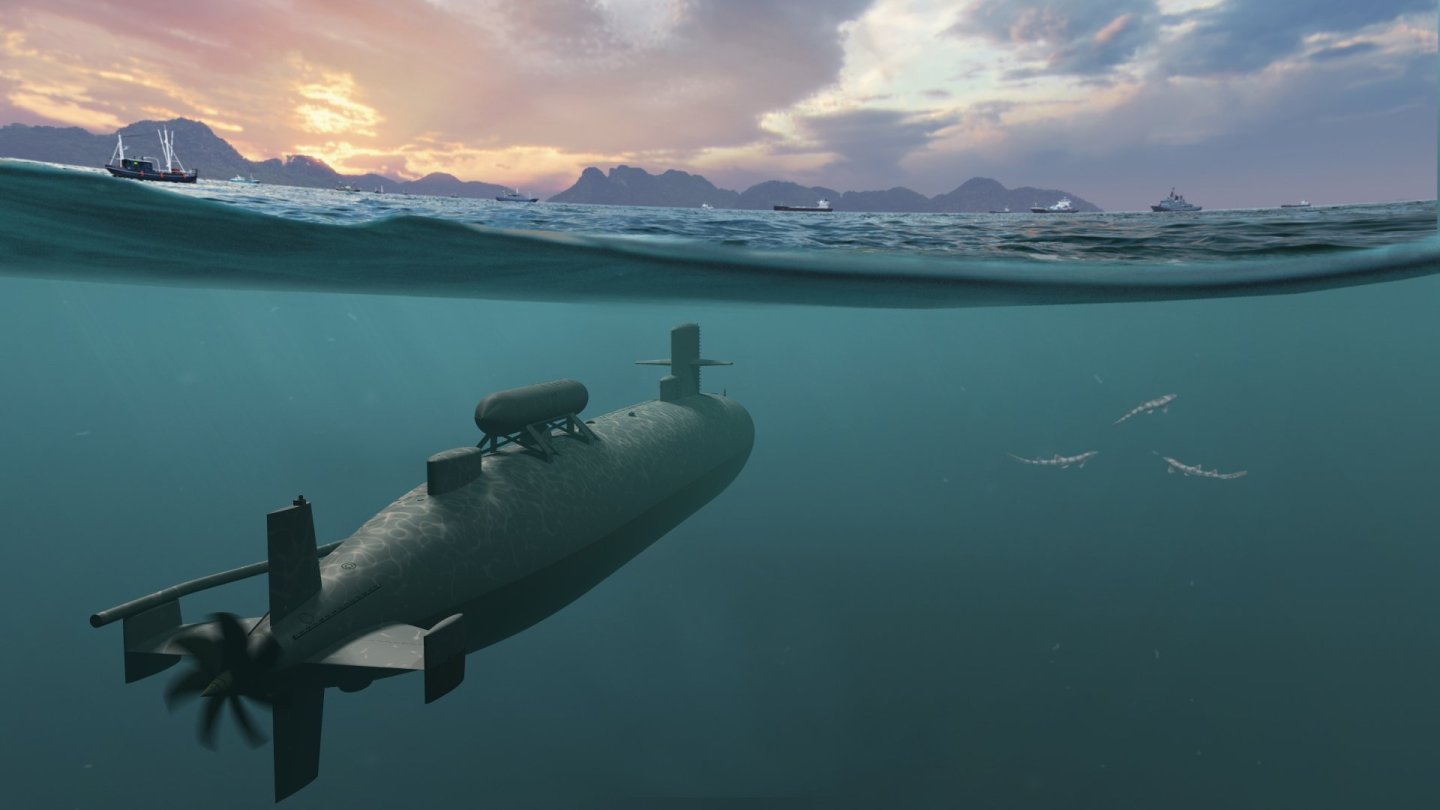
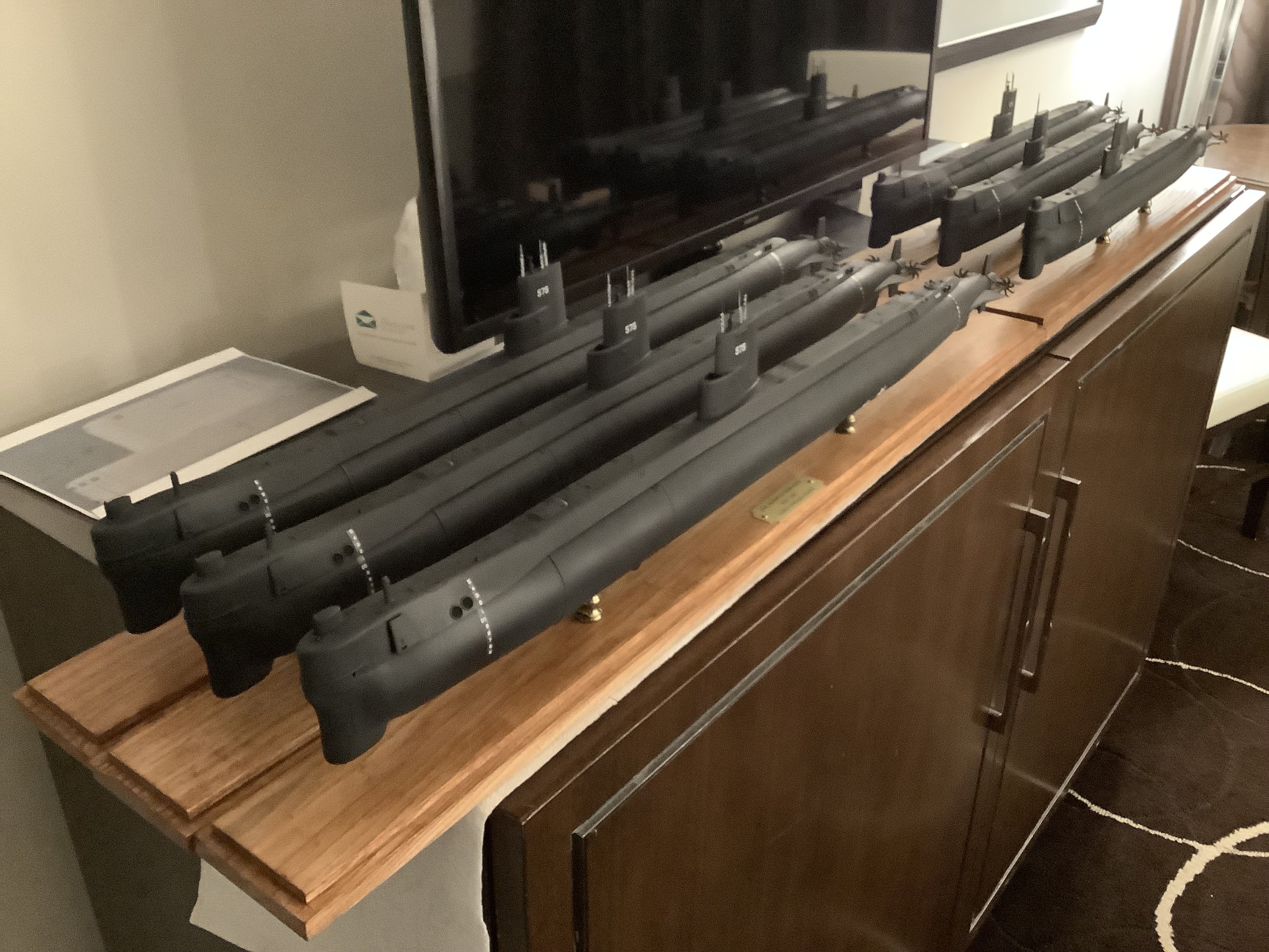
I just finished 3D printing a half-dozen 1/144 scale models of the original and modified versions of the USS Seawolf (SSN-575) to take as gifts to our crew's reunion a few weeks ago. All were a hit. Attached are a couple of 3D renders and photos of the completed hulls.


-
- 5
-

-

-
Lots of good replies posted in response to your questions. 1. I bought a resin printer five years ago, (Phrozen Mighty 4K) along with a cure station, (-also from Phrozen, using a turntable with UV lights surrounding it, with a UV-proof plastic cover) for just under $500 during an Amazon Prime Sale. I keep a log for each print to record how long they took, and any lessons along the way. The elapsed time is important since decent LED arrays are rated to 2000 hours. I'm on print #297 with zero issues with the printer. Any problem prints were my fault and easy to diagnose. Depending on the size requirements for your needs, you may be able to get by with a small printer. Check the print volume before pulling the trigger. I'm at the point now where I need a larger one and will upgrade soon. I'll keep the smaller one for small parts. I printed a set of anchors yesterday that took six hours to design, and an hour to print. Each is smaller than my small fingernail. The quality is always amazing! As for cleaning, I use one plastic tub to spray the build plate/printed parts with 91% IPA using an old Windex bottle, let them soak for three minutes, dry them with my airbrush set to 60 psi, then repeat the process once more. This saves a small fortune in submerging everything in IPA -as many other do. I dump the leftover IPA from the cleaning tub (usually about 1/8 of a cup) into the plastic-lined trash can next to my bench with some paper towels to absorb it. The trash can goes outside where the IPA can evaporate. I went from buying gallons of IPA, (and dealing with the aftermath) per year to a few quarts using this method. A foam brush also helps when cleaning large parts. If I find any residue, I use an IPA-soaked cotton swab to clean it, and blast it with air to evaporate any remaining IPA. After that, I place the build plate in an identical plastic container with enough hot water to submerge the build plate to cover the surface the parts are adhered to. The hot water loosens the parts and expands a miniscule amount allowing the parts to be removed with a slim metal spatula. I let the removed parts soak for a couple of minutes making part support removal easy. For some smaller parts, (like the aforementioned anchors) I leave the supports on, since fishing them out of the water is a PITA. Once all the parts are out, I blow-dry them once more. Some people like the vortex cleaning stations, but again, you're dealing with a larger mess when trying to cure/re-filter IPA in bulk. Time is one thing I never seem to get enough of. 2. Resin is a skin irritant and any resin dust from sanding is not something you ever want to breathe. Nitrile gloves are needed when handling uncured parts. A respirator and is recommended when sanding large parts. Eye protection should be worn anytime liquid resin is present. Some resins put out stronger fumes than others. Unless you have a dedicated indoor space with a good way to ventilate it (via air extractor venting outside) the garage is the place to print. Spill resin on indoor carpet and you're in real trouble. Carpet should never be near a workbench anyway. 3. Temps. Resin changes viscosity (thinner when hot, thicker when cold) which can greatly affect how the parts print. Ideal temp is between 70-75 for most resins, but check the mfr's recommendations before ordering any. In New England, I was limited to printing during warmer weather. You can use a heated enclosure made for 3D printing but if the duty cycle is too great, print quality will suffer. I compromised when I moved to Arizona three years ago on a two-car garage (I wanted the extra work space afforded by a three-car garage) but changed my mind because this one came with a dedicated heat pump - I can print year-round now in comfort with consistent results. I had to replace the large, cylindrical hot water heater to a small, wall-mounted on-demand unit that is more economical, freeing up additional space. If you're on social media, there are plenty of manufacturer sites where members can bitch and moan, with lots of failed print pictures. Besides keeping a personal print log, this is another great way to learn from other's mistakes, or learn how to troubleshoot (very rare) hardware failures. Like I mentioned, my printer has been trouble-free. The majority of my prints take 15-18 hours, and it works as well as when I first started. A handy tool in my arsenal is a Phrozen Cure Beam. This works well to cure small parts in < 10 seconds or the inside of the hulls I build. A set of silicon mats, (resin doesn't stick to them are under my printer, (in case of a printer spill) and my work area where I clean parts. Any printer that comes with a hook to hang your build plate to drip dry is a bonus. It recovers a little bit of the excess resin and decreases the amount you need to clean off the top of the plate by hand. I used an FDM printer to make a hanger for mine that I found for free on Thingverse. When I switched from FDM to resin printing, (far less sanding and resolution you'll never get from a .2" nozzle extruding hot plastic) I didn't like the cleaning phase, but once you get used to it, (and see the quality of your printed parts) it isn't a big deal and takes 15 to 30 minutes - 45 min or so if you print fifty parts at a time like I sometimes do. If you have any more questions, fire away. Someone here will be able to answer them. CC
-
3D printing material question
CCClarke replied to CPDDET's topic in CAD and 3D Modelling/Drafting Plans with Software
FDM printing is ideal for those who enjoy sanding and aren't interested in small, detailed parts. Using wood-like material is irrelevant since it's going to be painted over anyway and usually requires a larger nozzle diameter, reducing details further. I cut my teeth on commercial FDM printers that cost thousands, and bought a $350 Phrozen resin printer just to see what it could do. I was immediately blown away by the intricate details it could produce. Minimal sanding was the icing on the cake. My time is the most important commodity I have control over. Cons: Resin printing requires a dedicated, well-ventilated space and parts cleaning can be messy, despite the vortex cleaning stations available. 91 IPA is one consumable along with resin, but I've learned how to minimize how much IPA I need, using a discarded Windex sprayer, foam brush, and compressed air (60 psi from my air brush) to blow the excess resin from the .1 to .4 mm details. A half quart bottle of IPA lasts weeks instead of submerging the entire part in a plastic bin and contaminating a larger volume of IPA which becomes less and less effective over time and then has to be disposed of. For test fixtures and jigs, I still like FDM prints and farm those out to friends to produce my designs. Learning how to properly orient parts in a slicer takes time to acquire -usually through multiple failures (part of the learning process.) Resin printing is not plug-and-play as advertised despite new advances in printing technology. Being able to create parts with injection-molded precision at home is pretty darn cool though, and worth a look if that's what you need. My first resin model renders (for an RC submarine project) and the printed results were virtually identical.
-
Decals for draft markings
CCClarke replied to g8rfan's topic in Painting, finishing and weathering products and techniques
I highly recommend this guy: Josh at BedlamCreations.com. He's my go-to guy for waterslide (white) draft marks. I told him what font I needed, and he scaled multiple sets for me. Easy to work with and reasonable pricing. CC -
Beginner CAD recommendation
CCClarke replied to krith's topic in CAD and 3D Modelling/Drafting Plans with Software
There could be as many recommendations as there are different software applications for beginning CAD users. Two of the most powerful and popular CAD applications: Fusion 360 has a free version and there is a lot of free training available. The same goes for Blender. -
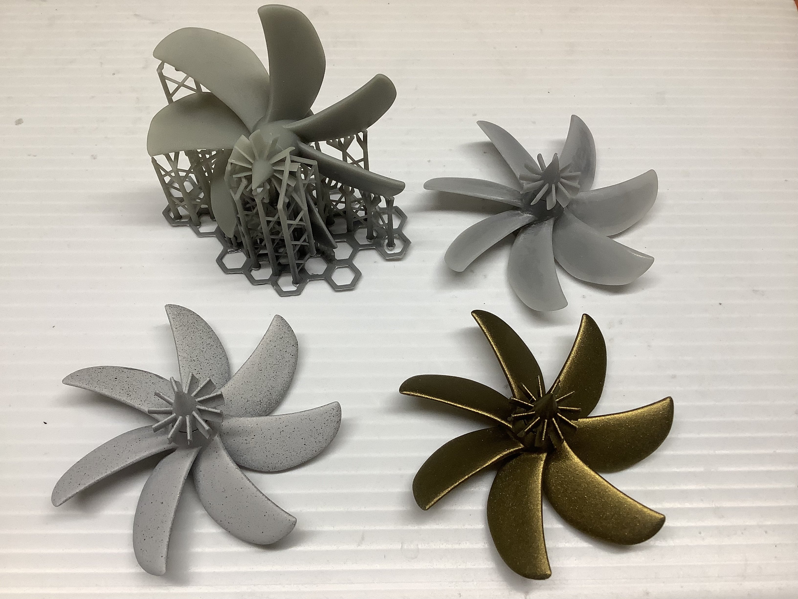
Jeff, Are you a proficient SolidWorks modeler? If so, there is unlimited potential for use of a 3D printer in this hobby over "old school" fabrication, which is another art form. 3D printing vs established model building methodology has and will be debated for years. I believe there is more than enough room in our hobby for both techniques. A digital fabrication workflow from design to finished part has advantages that are hard to beat, especially being able to up-rev a design and repeatability. I know one master modeler who makes his own propellers the old school way, then makes a mold to cast metal parts. His excellent skills produce a first part measured in days, sometimes weeks as he solders the brass blades onto the hub with a template, then files the filets to a smooth finish. While I certainly marvel and appreciate the skills to produce parts this way, the time required to get the same effect with perfect tolerances can be drastically reduced with a digital design workflow, which is another form of creativity once digital design (or CAD) techniques are mastered. Time is one of my two most precious dwindling commodities, (the other being my health) so I prefer using the newer technologies available to enable me to make the most use of it. The additional time saved translates to more model-building opportunities. Once painted, I doubt most observers can tell the difference between a hand-machined cannon or cast part or a digitally printed part.
-
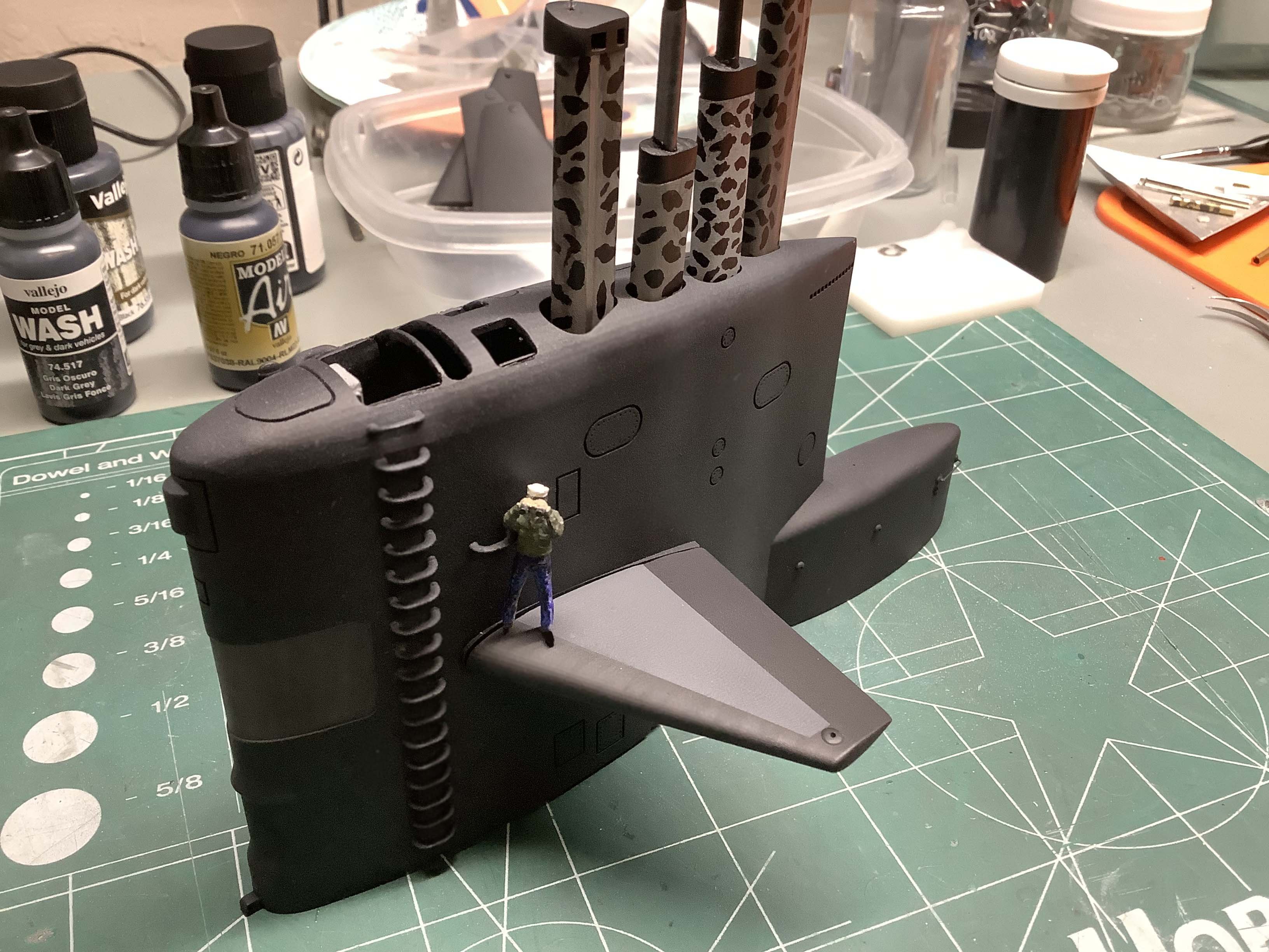
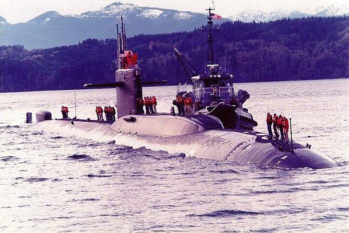
This is her in her second Ocean Engineering revision on the day she arrived for her homeport change from Mare Island to Bangor, WA in Nov '94. I rode her in when this picture was taken. As you can see, the hull is covered in SHT, (anechoic tiles) which ought make 3D modeling fun. The extra lengthening of the hull required larger fairwater planes for better depth control, so a pair of Los Angeles class planes were installed, higher on the sail.
-
Just checked their website and it says the veteran's $20 fee is not renewable. The license period is a one-time deal for one year. CC
-
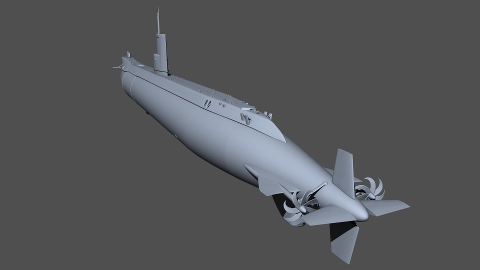
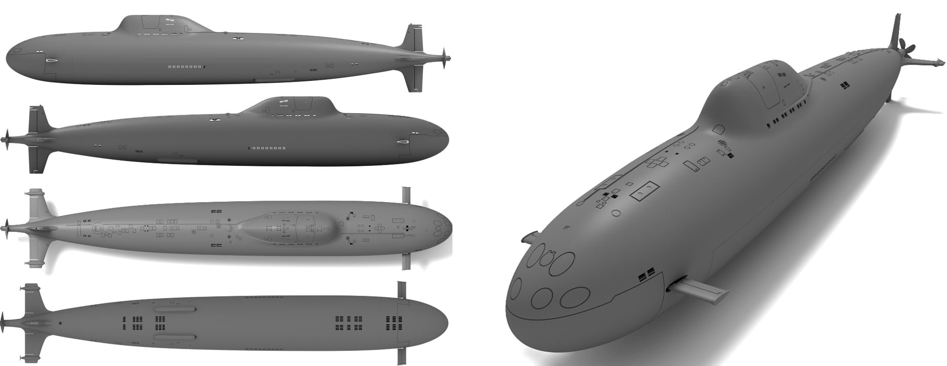
Final set of 3D model renders in submerged configuration with all masts and antennas lowered. And it's on to the next project!
-
3D printing material question
CCClarke replied to CPDDET's topic in CAD and 3D Modelling/Drafting Plans with Software
I use Phrozen ABS-like resin (compatible w/8k) exclusively. It flexes without shattering and handles reasonable (110 direct sun in AZ for hours) heat without warping. Highly recommended. -
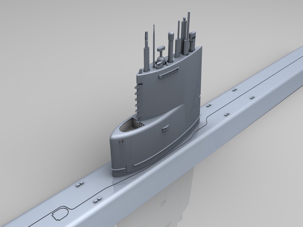
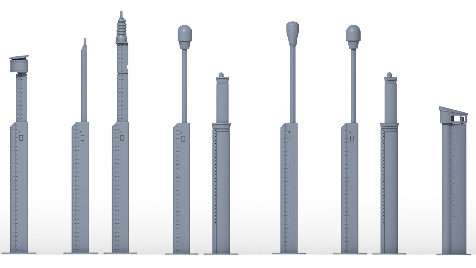
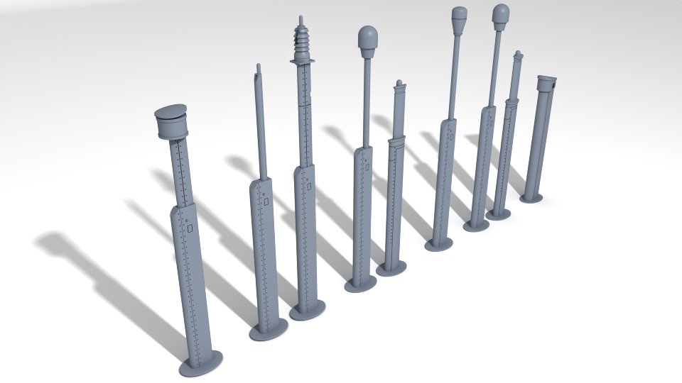
Added another set of US SSN submarine masts and antennas. They are paired in their relative positions, with one slot for future growth available. The radar and snorkel at each end are located by themselves, fore and aft on the sail. These print out nicely in 1/72 scale and larger. CC
-
- 2
-
-
Cold War madness
CCClarke replied to Martes's topic in CAD and 3D Modelling/Drafting Plans with Software
If you like that, consider: Command Modern Air/Naval Operations: Fully immersive, excellent graphics, with customizable, real-world scenarios and weapons. -
This guide might be of interest to anyone painting WWII U-boats. CC https://www.u-556.de/images/pdf/uboat_colours.pdf
-
- 2
-
-
What should I avoid when creating *.stl files?
CCClarke replied to Jsk's topic in 3D-Printing and Laser-Cutting.
Just found this site hidden in a folder. When manually orienting a print, the first question that comes to mind is, what angle is best? I often opt for 30/30 (pitch and roll) but sometimes it isn't suitable because the part is too large and those angles would have it extend beyond the build plate. Here's one way to determine the best print angle for a resin printer that might be of help: Angle calculator for smooth surfaces in resin printing – RC87 -
What should I avoid when creating *.stl files?
CCClarke replied to Jsk's topic in 3D-Printing and Laser-Cutting.
Since the OP is using resin printing, I'm trying to avoid discussing FDM printing in detail, but comparisons are useful for anyone on the fence regarding which technology is best for their needs. I've attached a few shots for comparison for the same shapes but with differing numbers of sides to illustrate polygon faceting. Each set shows the mesh on the surface and the surface without the mesh. (Multiple display modes are essential to object modeling. I hope the all-quad polys in the examples are large enough to show the differences. The sphere on the left has 24 sides with 12 segments. The one on the right is doubled with 48 sides and 24 segments. If you look at the edges closely, you can see the faceted surface more pronounced on the sphere on the left. The cylinders have 24, 48, and 180 sides from left to right. Increased geometry creates a smoother surface. At some point, adding additional geometry becomes overkill. If you print tiny parts, you can get away with less geometry, but large parts will show the difference clearly. It all depends on what look you need based on the part being printed - unless you're a masochist that enjoys sanding. All STL (and OBJ) files are triangle-based, meaning a four-point polygon is halved diagonally. Th eg-code printers use is triangle-based. Triangles also eliminate non-planar polygons, since a triangle can't be "bent" no matter how the three points are connected. Non-planar polygons don't render properly, but that's irrelevant to this discussion. When modeling, I always use quads, (four-point polygons) and they're automatically converted to tris, (three-point polygons) if the file is exported as an STL or OBJ. If I need to reverse-engineer an OBJ file, the triangles must be combined into quads for ease of mesh manipulation.


-
What should I avoid when creating *.stl files?
CCClarke replied to Jsk's topic in 3D-Printing and Laser-Cutting.
A higher poly count can bog some computers down during the modeling phase, but I have never experienced detrimental effects on the slicer's performance. Look at models on ThingVerse and note how faceted many are because the modeler didn't add enough geometry. There's a noticeable difference between a 48-sided cylinder and one with 360 sides as far as smoothness/finish. It's a common mistake that can ruin an otherwise nice effort. Orientation angle depends a lot on the geometry of the object being printed. If designed well, I can print hull sections vertically without a problem and all support attachment points remain hidden, cutting laborious post-support removal cosmetic restoration for a smooth finish. For smaller, organically-shaped parts, I'll start with auto-orientation before adding additional supports manually. Optimal printing results are a combination of experience and a well-designed part. Mistakes are part of the learning process if they aren't repeated. Keeping a Print Log adjacent to the printer for every print has been invaluable, allowing me to track how many hours I have on the printer's screen, maintenance and record problems and solutions. I've added a handy guide I hope will illustrate my post more clearly. CC Proper Part Orientation.pdf -
What should I avoid when creating *.stl files?
CCClarke replied to Jsk's topic in 3D-Printing and Laser-Cutting.
I'll show you my two go-to tools I reach for often when post-processing parts after cleaning and support removal, which begs the question: Is your friend the printer giving you completed/cured parts with or without supports removed? But first, The Why Most 3D prints will have tiny pock marks where the supports contact the part. It takes a little practice, but with experience, you can manually place the supports in areas that any leftover support blemishes aren't visible. This is a good reason why the (vertical) orientation of the stern in the last shot above prints so cleanly. Most of the support structure is located inside. Even though I usually use the Automatic Orientation and Support functions in Chitubox Pro, I still add a few where I think they'll improve the part quality. Just for educational purposes to illustrate the differences between vertical and auto part orientation, I've included one sliced vertically-oriented Stern, and two shots of the stern from different angles after slicing in Auto Orientation mode. The print time differences aren't too drastic, (displayed on the left side of the slicer screen) but the number of supports contacting the exterior is. Which one would you rather touch up after the supports are removed? To fill the tiny pock marks, I apply resin to the area, smooth it with a cotton swab, feathering the edges and use a UV curing wand to cure the area. Another swab dipped in IPA, followed by a couple of swabs dipped in water get the surface ready for sanding. I've found this reciprocating sander from DSPIAE to be invaluable to reach places my other sanding tools can't and it quickly smooths the surface. There's a tip for every occasion supplied along with a few sheets of pre-cut adhesive-backed sanding paper. The Phrozen Cure Beam UV wand (a pair are supplied) is the perfect way to cure resin after applying it to the hull for support contact repairs, interior spaces that a standard cure station can't illuminate properly, or bonding parts and filling the leftover seams after filling them with resin. These have saved me hours of re-work and I highly recommend them. Both are available on Amazon. CC


.thumb.JPG.6c28883ff209ca389c056fb65b8f855a.JPG)

-
What should I avoid when creating *.stl files?
CCClarke replied to Jsk's topic in 3D-Printing and Laser-Cutting.
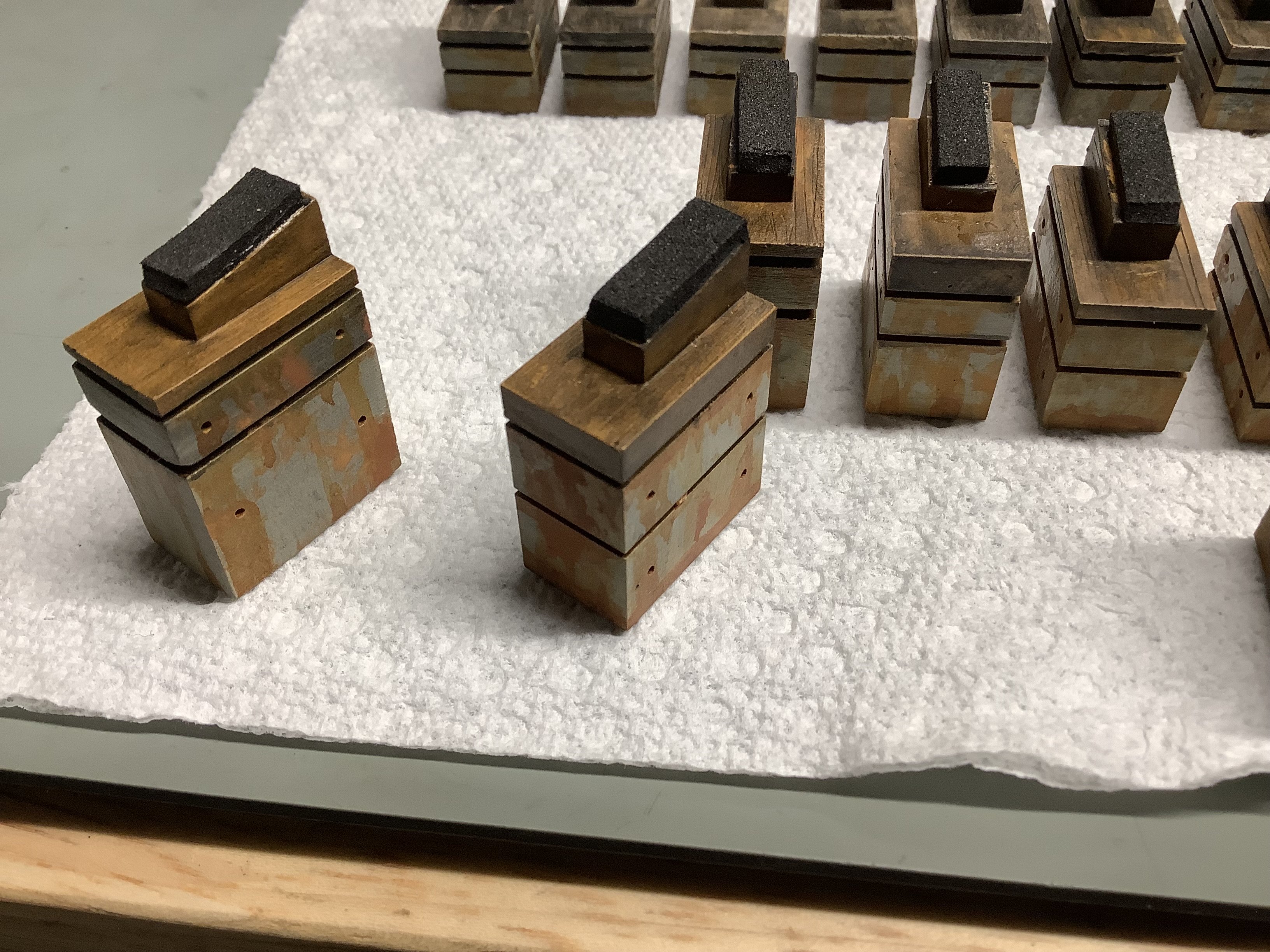
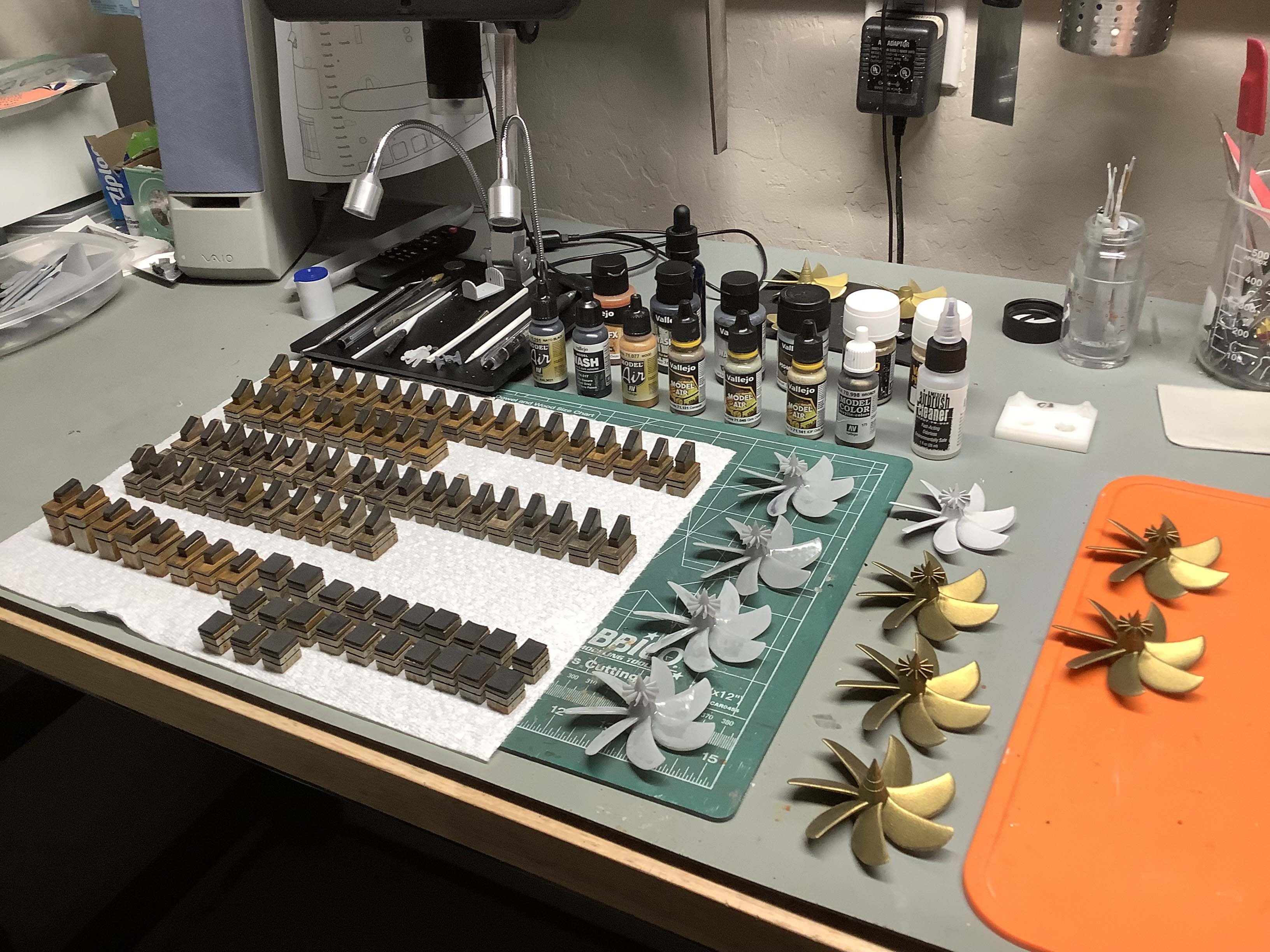
Lots of good information here. I'll try to add a little more. Since you aren't doing the printing, I won't get too technical. These are requirements before starting any resin print: 1. The printer build plate is level/calibrated. 2. Slicer settings are calibrated for the resin being used. 3. Printing is performed in a temperature-controlled environment. Your first picture speaks volumes. Most parts, (especially long, thin ones) are tough to reliably print parallel to the build plate, (no matter how well supported) without problems, though there are exceptions. Parts need to be angled -or vertical, depending on the design when hanging from the build plate. All of the "Pro" slicers, (usually an upgrade from the vendor's free version) include auto-orientation. In most cases, the slicer-determined part angle is adequate, but it depends on the design of the part. You can print parts vertically, (suspended from the raft by supports) if they follow certain design guidelines. A part with gentle contours is ideal. Any overhangs parallel to the build plate require supports, but orientation is an important consideration for best results. The first two pictures I've attached illustrate this point, with two types of orientations, (Parallel to the build plate and angled) based on the part's geometry depicted. The torpedo afterbodies are vertically printed, with supports under the mid-point where the forebody will be bonded. Since its a flat surface, and subject to micro-sagging, a little sanding will quickly remove any support artifacts. FYI: The control surfaces are oversized-since these are meant to be handled by young students as part of a STEM outreach program I'm involved with. Magnets are bonded inside the body in the two places the torpedo contacts the stand, (also containing magnets) allowing the model to be removed and passed around. The slope of the top section flares away from the main body gently, requiring minimal support structure. A (unseen in the shots) hole inside the torpedo propeller shroud where the propellers live also serves to prevent suction forces from deforming the part during the build plate lift cycle. The supports that run parallel to the body are latticed, meaning the supports brace one another, minimizing the chance of a support failure that would lead to deformation of the area they're supposed to be supporting on the model. Layer lines are minimal, and the supports are easy to remove. Note the rafts on the build plate. These use less resin than a full raft and make it easier to remove the parts, minimizing breakage. Note the (3) torpedo mounts are angled. (Each torpedo requires two.) This ensures the mount's flat faces remain flat. I could have angled the torpedoes, but there would be many more support artifacts on the model that have to be filled and sanded afterwards. I'd rather wait longer for a vertically oriented print, (more layers than if it were at an angle = longer print time) than fill support pock marks with resin manually, then cure and sand. (I'm lazy that way.) The 4th and 5th pictures below illustrate thin, round part orientation for submarine sail handrails. Angled "skate" style rafts are used to minimize breaking during removal from the build plate. The part orientation works with the curve of the handrails, so they are built-up gradually while printing. -Notice the supports where they attach to the rails. Most are interlocked and all feature pointed tips where they contact the part. The four upper and lower rudders have a 3mm hole for a brass shaft. See how the holes gently slope upwards at the bottoms and then curve upwards at the top? No supports are needed, and the holes have perfect geometry and more importantly, dimensional tolerance, which is press-fit. Even the bridge compass, (the two smallest parts) have tiny handles about .1 mm thick. Properly angled, these print perfectly. Modeling: You said you're using a Sub-D modeling app. Are you "freezing" the sub-D polys with a high enough sub-division level before saving the file? Higher levels minimize faceting insuring the best possible surface finish. A lot of designers mistakenly believe a slicer will make the model's geometry smooth. Slicers can add vent holes but cannot change the model outward appearance otherwise. As mentioned, sacrificial stand-offs can be used for certain parts but require removal/re-finishing post-print. The 6th picture shows an example, with the sacrificial supports highlighted in orange. The last picture shows how I set it up for printing in the slicer - I added supports to the lower sacrificial supports, but the uppers were left alone. The lowers would probably print fine without supports, but why take a chance on a long print? The stern of the VA class submarine is printed vertically. The hull slopes inward, supporting the previous printed layer without supports. The stern planes, dihedrals, and shroud stand-offs all use sacrificial supports modeled into the stern. These angle outwards, supporting the outward angled parts of the stern and get cut out after curing, without the need for standard supports. You want to model them very thin and/or add a slight beveled inset where they meet the hull for easier removal. Properly removed, a little sanding erases any hint they ever existed. Modeling error-detection/correction: You already know what a PITA this can be to properly correct. Occasionally, errors are detected by the slicer when the part is imported. Most of the Pro-version slicers are able to eliminate most problems, but I try to correct them in the modeling phase before exporting as an OBJ/STL. If you have a feature in your modeling program that allows you to merge nearly coincident points in the mesh that's a plus. Merging points can create 2-point polys, which will be identified by the slicer as non-manifold polygons. Those have to be found and removed as well. I'll stop here. If you have any specific questions related to printing that I haven't answered clearly enough, feel free to ask questions and I'll try to do better. CC.thumb.JPG.dcde2f932247ce80ee61d0edf066fc74.JPG)
.thumb.JPG.cac57983ae29964def8d6fd4d8c3aec9.JPG)

.thumb.JPG.a6224dca4d8daf9af9a5142f47617c85.JPG)
.thumb.JPG.cb401524980ca1c941e66f79857d5272.JPG)


-
Round-nose pliers as stated, come in multiple diameters. Their chief use has been in the electronics industry for decades to form wires prior to attaching them to terminals and posts. I attended a very tough NASA-level electronic repair course once where any marks left on the conductors resulted in a failed inspection. We placed Kapton tape on the ends to prevent any noticeable conductor deformation. I continue to use these for my ship-building, and still wrap the ends. Precision flat nose pliers are also very useful. CC
-
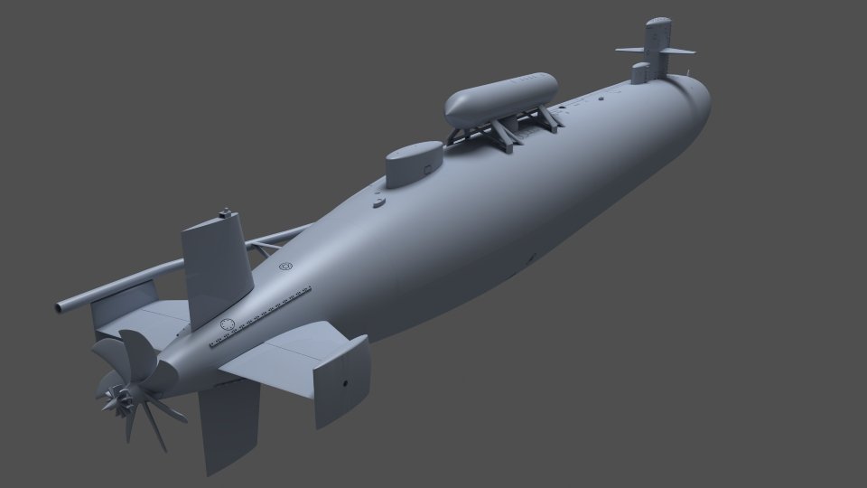
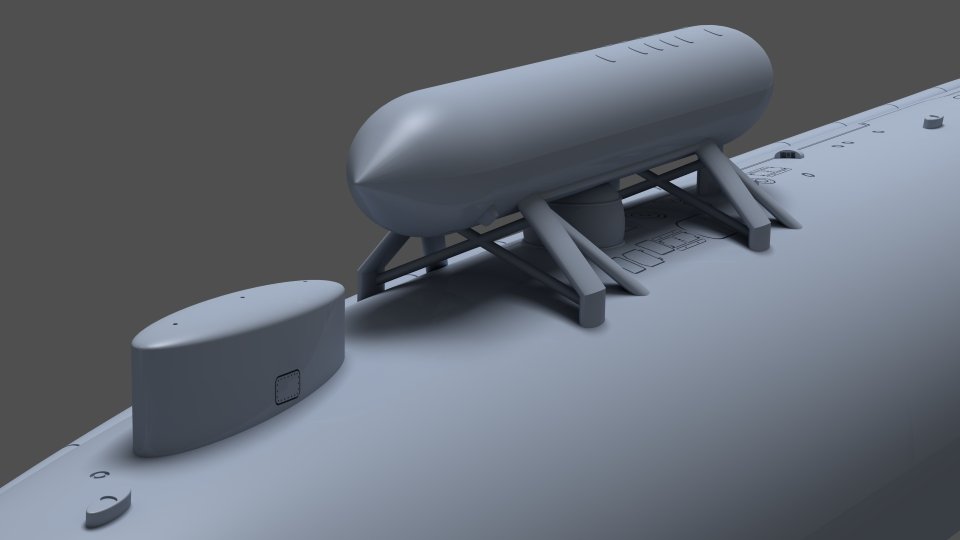
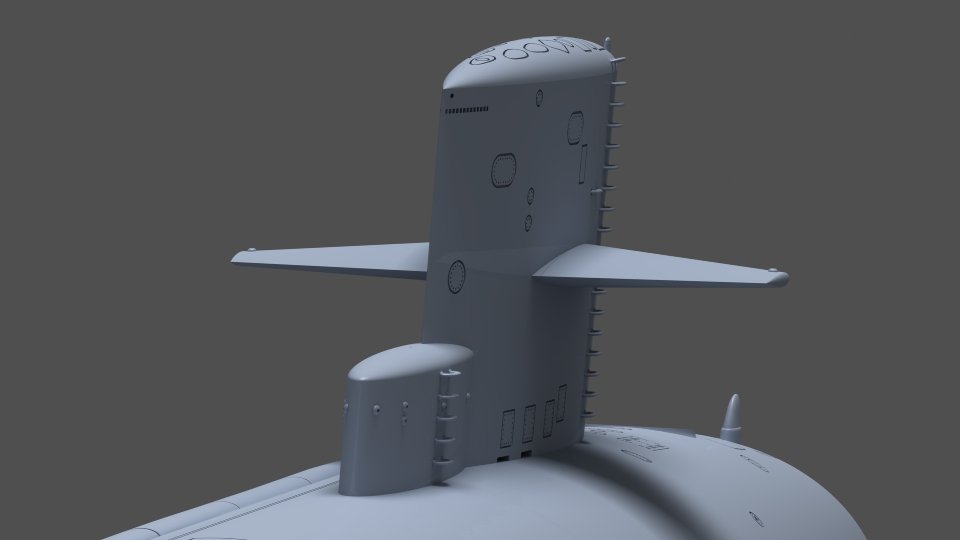
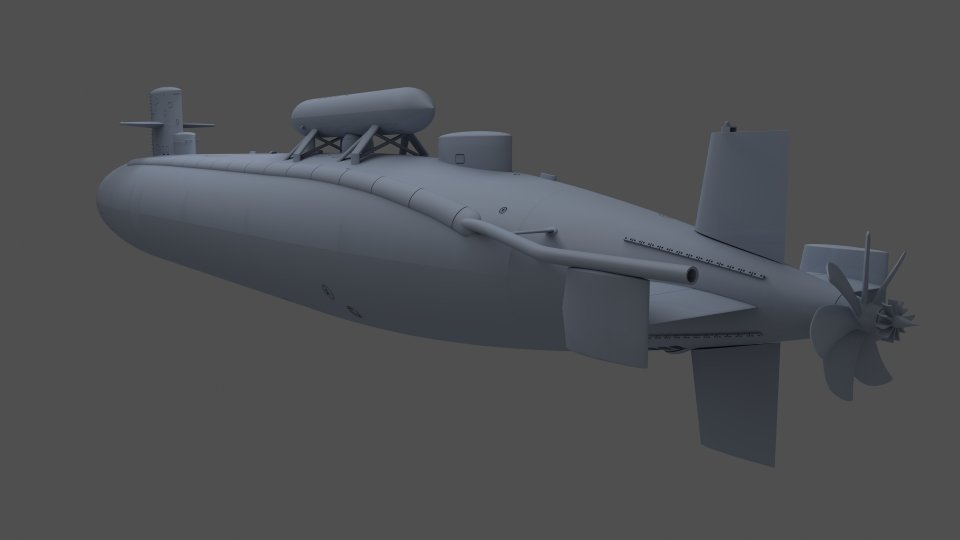
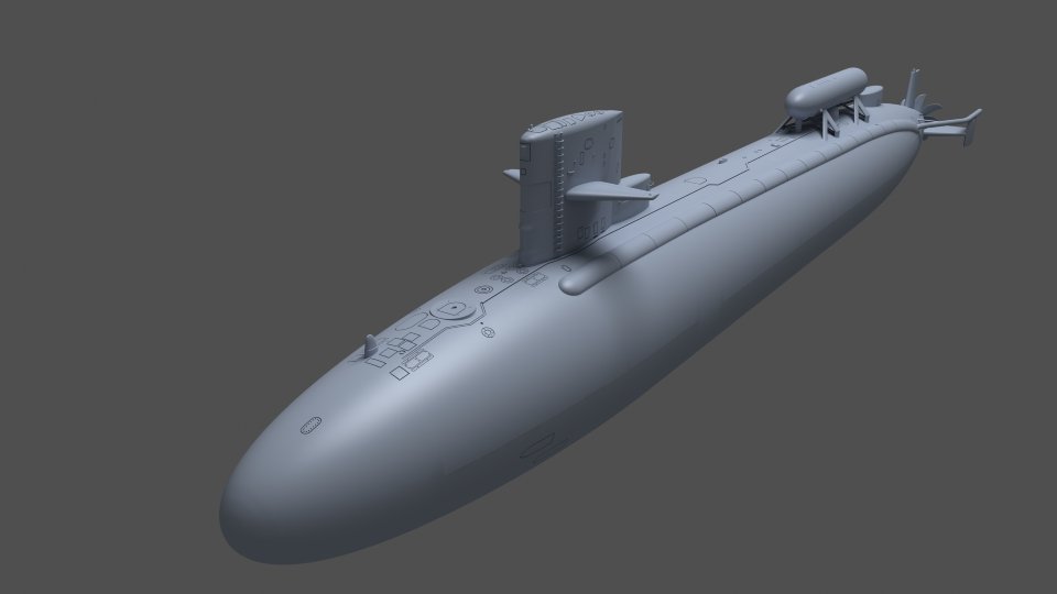
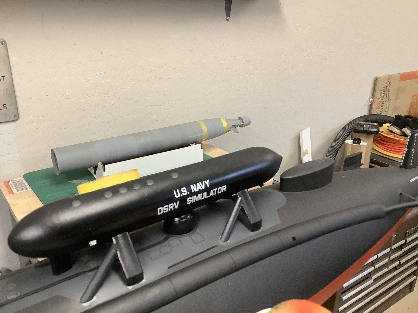
Old thread, but nice to see, since I specialize in designing and 3D printing (resin) of US Nukes. Attached are a couple of shots of my latest work for a museum project; (a Sturgeon-class boat as well): USS Parche as she appeared in the early 80's in 1/72 scale. Since the latter version of the ship, (extensively modified again in the early 90's) has a 100' extension forward of the sail, I'll re-use the aft portion, (minus the DSRV Simulator atop the aft escape trunk) and re-model the forward half of the boat. After weathering the lower hull, the sail and DSRV sim will be bonded to the hull and made ready to be mounted on 90 keel blocks, bonded to a base painted to resemble a concrete drydock basin. I also included a render of the 3D model in the wild.

.thumb.JPG.6430ae9d3a638ede96b0ebe408419693.JPG)


-
I use photos to build 3D objects when detailed plans aren't available. The process isn't simple or fast, but it's possible if you have the modeling experience. When I think I'm close, I place the photo in the background and rotate the model to approximate the photo, then change anything that doesn't match up. These are relatively simple models, which helps.


.JPG.86899f0da1ceffcecb0f98c52c0eb39f.JPG)

.JPG.8432031c7109a20dd1abd41a7e3084fe.JPG)
.JPG.7f9db2d3c207c8cbd3e40e137818e24f.JPG)

.JPG.a45668040d6869d75ec2713335b165aa.JPG)
.JPG.b3a73ba5ce4227504e49000d608e4290.JPG)
.JPG.c701613259f52ad82f42ccfd163e85d8.JPG)