
LJP
-
Posts
170 -
Joined
-
Last visited
About LJP

Recent Profile Visitors
2,286 profile views


-
 Canute reacted to a post in a topic:
SS Klondike II by John Ruy - 1/8” = 1’ (1/96 scale) - Sternwheeler Riverboat
Canute reacted to a post in a topic:
SS Klondike II by John Ruy - 1/8” = 1’ (1/96 scale) - Sternwheeler Riverboat
-
 LJP reacted to a post in a topic:
SS Klondike II by John Ruy - 1/8” = 1’ (1/96 scale) - Sternwheeler Riverboat
LJP reacted to a post in a topic:
SS Klondike II by John Ruy - 1/8” = 1’ (1/96 scale) - Sternwheeler Riverboat
-
LJP reacted to a post in a topic:
SS Klondike II by John Ruy - 1/8” = 1’ (1/96 scale) - Sternwheeler Riverboat
-
Keith Black reacted to a post in a topic:
SS Klondike II by John Ruy - 1/8” = 1’ (1/96 scale) - Sternwheeler Riverboat
-
 John Ruy reacted to a post in a topic:
SS Klondike II by John Ruy - 1/8” = 1’ (1/96 scale) - Sternwheeler Riverboat
John Ruy reacted to a post in a topic:
SS Klondike II by John Ruy - 1/8” = 1’ (1/96 scale) - Sternwheeler Riverboat
-
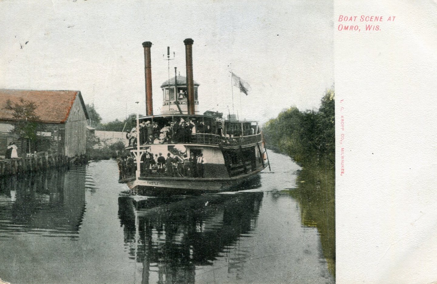
 I am aware of a few sternwheelers. S. S. Klondike, Whitehorse S.S Nenana, Fairbanks S. S. Moyie, Kaslo, B.C. S. S. Sicamous, Penticton, B.C. I am certain there are others but these are the ones I am aware of. LJP
 -
LJP reacted to a post in a topic:
SS Klondike II by John Ruy - 1/8” = 1’ (1/96 scale) - Sternwheeler Riverboat
-
Harvey Golden reacted to a post in a topic:
J H Crawford by LJP (Lawrence Paplham) - Scale 1:64 - an 1894 to 1898 Wisconsin sternwheeler
-
Harvey Golden reacted to a post in a topic:
J H Crawford by LJP (Lawrence Paplham) - Scale 1:64 - an 1894 to 1898 Wisconsin sternwheeler
-
Harvey Golden reacted to a post in a topic:
J H Crawford by LJP (Lawrence Paplham) - Scale 1:64 - an 1894 to 1898 Wisconsin sternwheeler
-
Siggi52 reacted to a post in a topic:
J H Crawford by LJP (Lawrence Paplham) - Scale 1:64 - an 1894 to 1898 Wisconsin sternwheeler
-
JacquesCousteau reacted to a post in a topic:
J H Crawford by LJP (Lawrence Paplham) - Scale 1:64 - an 1894 to 1898 Wisconsin sternwheeler
-
gsdpic reacted to a post in a topic:
J H Crawford by LJP (Lawrence Paplham) - Scale 1:64 - an 1894 to 1898 Wisconsin sternwheeler
-
gsdpic reacted to a post in a topic:
J H Crawford by LJP (Lawrence Paplham) - Scale 1:64 - an 1894 to 1898 Wisconsin sternwheeler
-
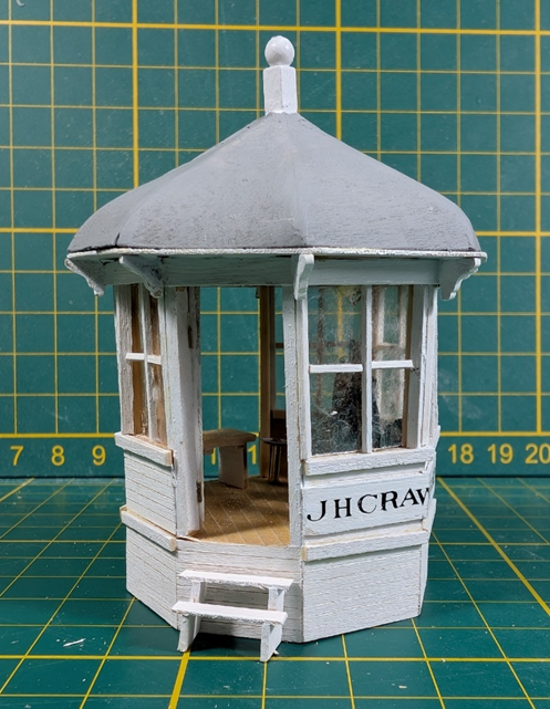
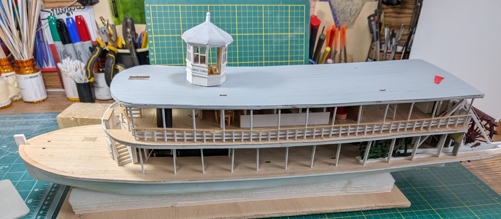
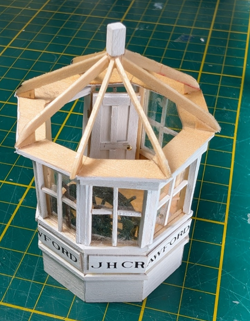
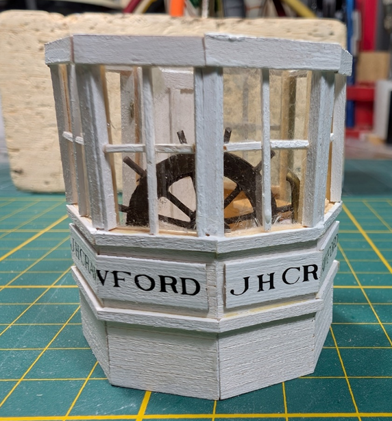
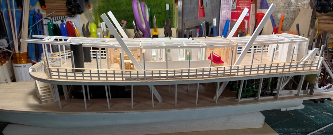
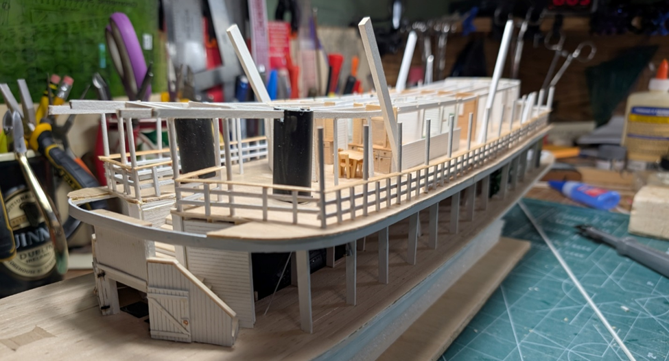
Keith and John, MANY thanks for your kind input! The pilothouse is done. The rest of the pilothouse panels went quickly after I figured out what I needed to do. A couple of shots of the finished product. The roof brackets have been added, the stairs to the pilot house, and the painted roof. I did not know what colour to pain the roof so I used the same grey as the hurricane deck. “Colourized” picture postcards were not really helpful. They portrayed anything from a bright red to a possible silver and gold metallic. I could tell from the JHC photo that it was dark and shiny, but no idea what it could have been. Another shot with the pilothouse placed but not affixed to the hurricane deck. The next step will be something easy on the hurricane deck, probably ventilators and water tank. There are lots of items to put on the hurricane deck including stacks, a bell, lights, and numerous odds and ends. But it is much simpler than Thistle was. Once that is complete, I need to do the bow attachments, rubbing strakes, &c.
-
LJP reacted to a post in a topic:
J H Crawford by LJP (Lawrence Paplham) - Scale 1:64 - an 1894 to 1898 Wisconsin sternwheeler
-
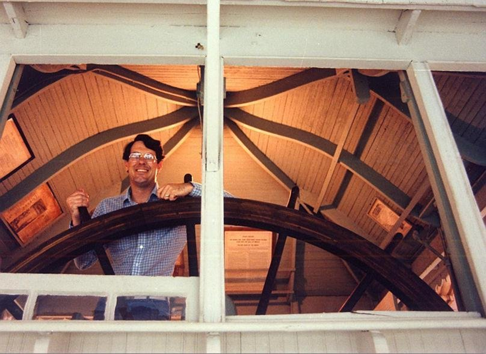
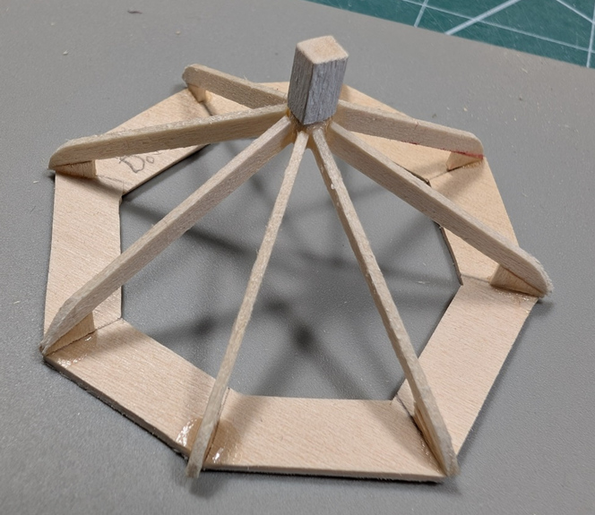
I thought that I would give more of an update on the roof instead of just recounting my tribulations. The roof has been a challenge even though I had built one for Thistle. This is an excellent photo the underside of the Golden Eagle pilothouse from Steamboat Museum Dave Thomson Collection [Steamboats.com/museum]. (No idea who the pilot is.) This is a square pilothouse but shows the construction detail for the roof. I added the supports for JFCs pilothouse roof. Originally, I used 1/32 plywood like I did for Thistle – but I did not like the results. So I went with 1/32 stock. I tried to think how the real boat would have done it. Instead of a single curved piece of plywood, I used two pieces of stock and curved the bottom. This is a real rough attempt after a few failures. The loose roof frame was added to the pilothouse for an idea what it will look like. I used birch veneer for the roof panels. I had issues. For the first attempt, I had lined and urethaned the underside and painted the top. But the panels were too stiff to bend for the bottom curve. So for the next try, I just lined and used water and heat to bend the bottom curve. Seemed to work better, but I will need to urethane and paint in situ. Here is what the first three panels look like. Now I need to finish the panels, paint and urethane, affix to the pilothouse itself., etc. The next step will be something else on the hurricane deck, probably ventilators and the water tank.
-
John said The wheelhouse looks great. I'm looking forward to your solutions for the roof structure! Unfortunately, John, so am I. I have tried to "improve" it over the Thistles, and I have had a few dumpster fires. Back to the drawing board. This will take more time. Cathead said That is really well done. Thanks Cathead, I really appreciate your praise. I have always respected your modeling abilities. Keith Black said Very very nice, LJP. The wheelhouse interior is a treat and will be really special to look into once the Crawford is completed. Thanks Keith. I always enjoy your builds but I will stick to a larger scale. Still a ways off until completion but headed in the right direction. Thanks all, LJP
-
Absolutely incredible! Your detail in such a small scale is unbelievable. Love the wheels! LJP
-
LJP reacted to a post in a topic:
Billy 1938 by Keith Black - 1:120 Scale - Homemade Sternwheeler
-
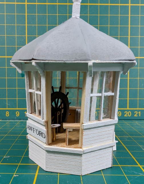
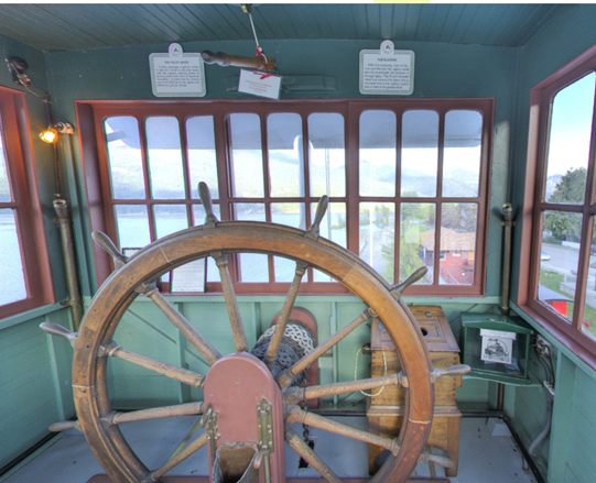
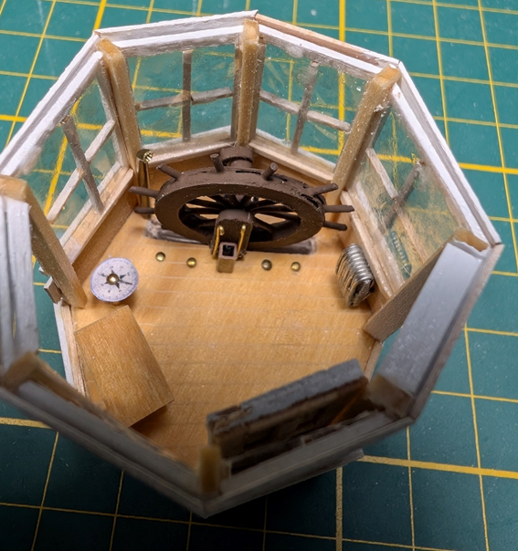
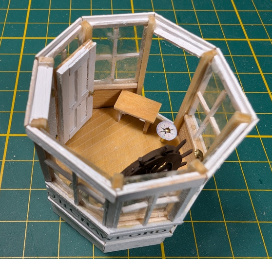
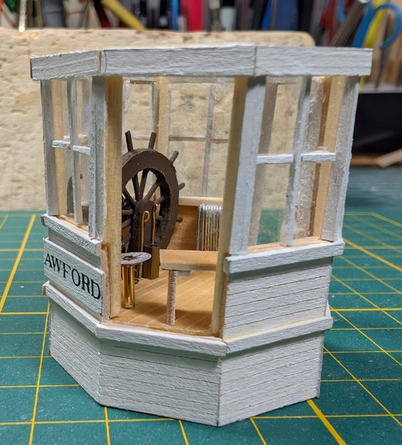
The lower part of the pilothouse has been completed. All of the windows are in and the interior finished. For the inside of the pilothouse, I used Bates and some photos of Moyie’s pilothouse. One of the photos of Moyie's pilothouse is below. Note the pea green interior which was prevalent in that locale. The box behind the wheel is a compass (and donation box). A radiator was in front of the wheel on the right-hand side, the lazy bench on the left. JHC probably had some type of a bench, but since it was not an overnight boat, the bench did not have to double as a bed. Again, I used a radiator as I never saw a chimney for a pilothouse stove. Radiators were appropriate for that time period. A few shots of the finished product are below. I used dry transfer lettering for the nameplate. A shorter boat name other than J H Crawford would have been easier on the nameplate. The next step is the challenging roof. I can assure you that beast will take some time and multiple versions will be made before the final product is created.
-
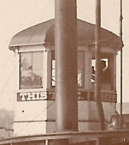
Cathead said "I wonder if the octagonal arrangement improved visibility by providing a straight-out view at eight different angles? The more "normal" square pilot houses found on typical riverboats would certainly have some more obscured perspectives as you looked through the glass at various angles. This could have been beneficial on lake boats where there could be traffic or obstacles in any direction, unlike riverboats with their more linear paths." Hi Cathead! I have no idea as to why an eight-sided pilothouse, but I think your reasoning is right on. JHC was designed for the Wolf River, which is both narrow and with lots of bends. Navigation on the Wolf was often described as very challenging and nearly impossible on a longer boat. Likewise, a "locomotive type lamp" was included on the boat so it could see around the bends. Good insight! LJP
-
JacquesCousteau said Great work on the pilothouse! Thanks much! I think the unusual octagonal pilothouse helps make JHC interesting. Keith Black said Very nice detail work on the pilothouse, LJP. As noted, not my first attempt on this one and I had done several on the Thistle. I have learned a lot in the process but also from all of you. John said Nice work on a difficult shape! Thanks much. I really like the design. I did talk to myself during this process and expect many more before I am done. Cathead said That's a really fiddly shape to work with and I can see why you've made a few tries. This one certainly looks like it's on the right path. Thanks. Getting the correct angles was one of the many challenges. It could always be better but I have tried my best. wefalck said Was there a particular reason, why she had an octogonal pilothouse? It looks rather cramped. The pilothouse was cramped. See below. The captain/pilot was really stuffed along side the wheel. I do have photos where he was actually outside the pilothouse on the port side. It was a small pilothouse: the wheel was "a bout six feet across" and I based my scale on that. Eastern riverboats and Great Lakes boats sometimes had this octagonal arrangement. The builders, Ryan brothers, had built ships and boats in both places. Thanks to all, LJP
-
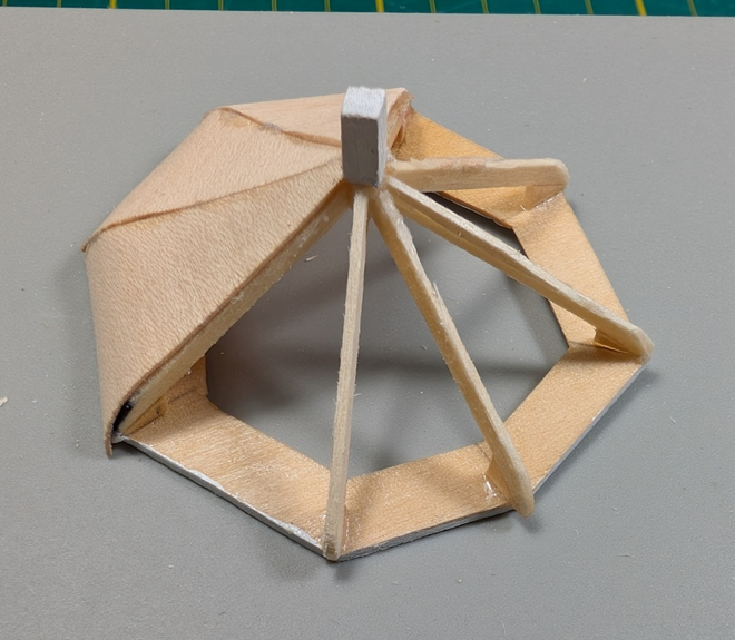
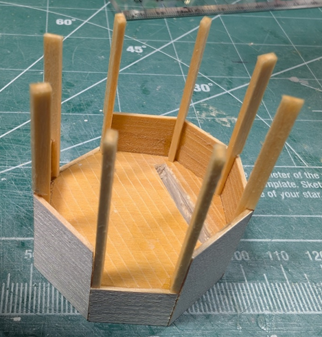
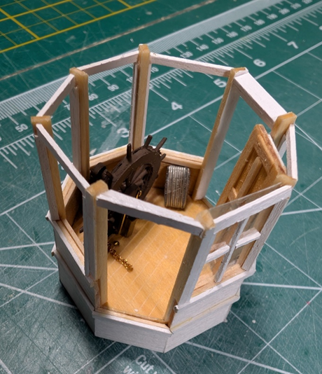
As expected, the pilothouse is taking a ton of time. And this is the second version. I thought I would give an update albeit well incomplete. I did not like how the Thistle’s pilothouse looked so I tried something different. Instead of a whole height panel, I built part of the panel up to the height where the window starts, and then supports that the window slides into. The cutout is where the wheel will be recessed into. The view is where the door will be, the opposite side is where it will be left open for viewing the details. I have just placed the wheel, radiator, and door in. They will be affixed later. I have one window in. The glazing is mica, with the grid 1/32 square stock. Other duties may delay this a bit, but now I need to finish the windows and put the cap on the pilothouse. After that is complete, I will do the roof.
-
LJP reacted to a post in a topic:
Billy 1938 by Keith Black - 1:120 Scale - Homemade Sternwheeler
-
Hi John, Thanks for the support! I did the canvas on the deck differently than I did on Thistle, and it looks better. I actually used glued down strips of normal 8 1/2 by 11 heavy duty paper. On Thistle I used tracing paper for the canvas. I know that Kurt used silk span on his Chaperon based upon recommendations from John Frayant. Cathead, Thanks again! I have loved your builds. I continue to work on the pilothouse, now the second version. This thing is taking forever, and it seems like I have accomplished little. But I want a better representation than I did on Thistle. The bottom half and the roof will be done separately. I will do pictures when I have more done on the bottom half. LJP
-
LJP reacted to a post in a topic:
Billy 1938 by Keith Black - 1:120 Scale - Homemade Sternwheeler
-
LJP reacted to a post in a topic:
Billy 1938 by Keith Black - 1:120 Scale - Homemade Sternwheeler
-
LJP reacted to a post in a topic:
Billy 1938 by Keith Black - 1:120 Scale - Homemade Sternwheeler
-
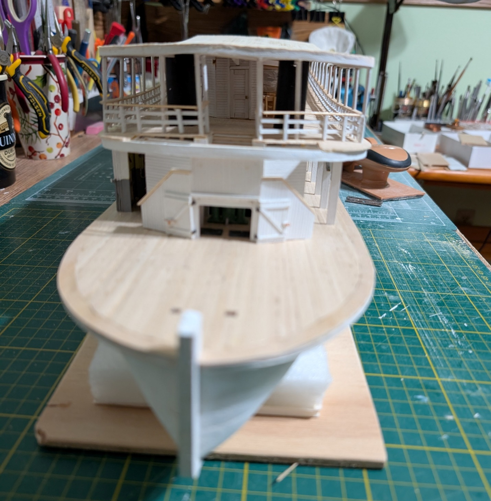
Hi John, Thanks for the support. The hurricane deck has been planked. It is now ready for the other structures, as stacks, pilothouse, water tank &c. The pilothouse will again be a challenge. For the planking, I used individual 1/32 by 1/8 boards that I had stripped from basswood stock. A different bow on view of the same. There is always the question as whether to use simulated tar paper or canvas for the hurricane deck covering. I chose canvas. I had actually seen canvas used on some of the derelict boats across from Dawson City. Likewise, it looked like canvas was used on the capsized Paul L. Canvas it was, “painted and sanded”. Canvas comes in 4, 5, 6 & 7 foot widths on up to 90-foot-long rolls. I used 5-foot width by about 60 feet long with a half foot lap on the seams. You really cannot see the canvas strips well on the photo. I still need to do the cut-outs for the hog chains and braces, stairwell, and observation port. Then I can get started on the pilothouse. The unusual octagonal pilothouse will take a while.


-
 LJP reacted to a post in a topic:
Billy 1938 by Keith Black - 1:120 Scale - Homemade Sternwheeler
LJP reacted to a post in a topic:
Billy 1938 by Keith Black - 1:120 Scale - Homemade Sternwheeler
-
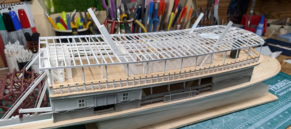
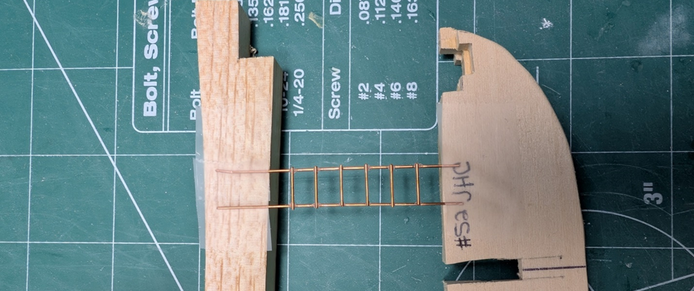
Carlines are done. The hog chain braces are still loose and need to be cut to length. I also included a template for the pilothouse. There are a few other cutouts on the hurricane deck. One is a (? viewing?) hatch that may have been used to allow the pilot a better vision when docking. Not completely certain what this was for but several of the Ryan built boats had these. Any of your ideas would be greatly appreciated. The other is the opening for the ladder from the boiler deck to the hurricane deck. This is what the unpainted ladder looks like. I get more model time and more done during a Wisconsin winter when the weather is conducive to indoor pursuits. Now it is time to plank the hurricane deck.
-
Keith, Thanks! Love your Billy build. Where you get these ideas and such a small scale never ceases to amaze me! John, Thanks for the kind words. Hope you are enjoying your summer down under. Cathead, Lucked out on JHC with the straight rails. I was not as lucky with Thistle, that was rounded at the bow. To all: Best of the Seasons to you and yours, and a great 2026. (I am NOT ready to acknowledge the start of a second quarter century in the 2000's. Seems like only yesterday...) LJP
-
Got the railings done. This is the same template that I used to make the railings for Thistle. And the finished product on the boat. The hog chain braces will be cut to length and glued in at a later step. Now time to add the carlines, cut the beams to length and plank the hurricane deck.
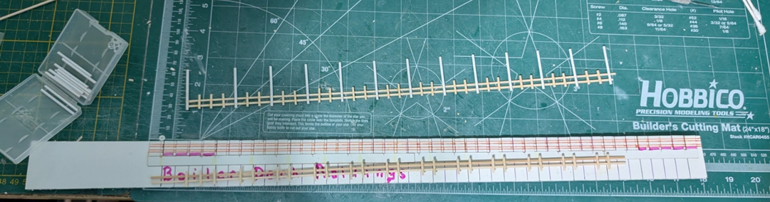
-
Hi John, JHC/Thistle had bow and stern sheer, probably due to travelling on the Winnebago Pool: Lakes Winnebago, Poygan, Winneconne & Butte des Morts. Sheer was normal for those boats. Those lakes could be volatile. As Thistle, there were reports of pottery crashing to the deck, furniture swept overboard, and buckets broken on the sternwheel. The Aquila had its superstructure destroyed, Cook had barges capsize and sink. The angle of my photo really accentuated the sheer; it was not that severe. One of my photo postcards shows Thistle/JHCs bow sheer: As for the hurricane deck being named as such, I have no idea. Maybe you or others can give us the history on that. LJP