


wefalck
-
Posts
5,537 -
Joined
-
Last visited


.thumb.jpeg.fc5d633a7b34428fcf19419a73d56d55.jpeg)


-
 wefalck reacted to a post in a topic:
AEG G.IV - Creature of the Night by DocRob - Wingnut Wings - 1/32
wefalck reacted to a post in a topic:
AEG G.IV - Creature of the Night by DocRob - Wingnut Wings - 1/32
-
Canute reacted to a post in a topic:
ZULU 1916 by Ras Ambrioso - 1/48 scale - stern paddlewheeler
-
trippwj reacted to a post in a topic:
Synoptical Dictionary of Nautical Terms. Gr; En ; Fr; Sp; Pr; It; Sw; Dk; Nl
-
mtaylor reacted to a post in a topic:
Canoa de Rancho by JacquesCousteau - Scale 1:32 - Lake Chapala Fishing and Cabotage Vessel
-
 wefalck reacted to a post in a topic:
AEG G.IV - Creature of the Night by DocRob - Wingnut Wings - 1/32
wefalck reacted to a post in a topic:
AEG G.IV - Creature of the Night by DocRob - Wingnut Wings - 1/32
-
wefalck reacted to a post in a topic:
ZULU 1916 by Ras Ambrioso - 1/48 scale - stern paddlewheeler
-
JacquesCousteau reacted to a post in a topic:
Canoa de Rancho by JacquesCousteau - Scale 1:32 - Lake Chapala Fishing and Cabotage Vessel
-
wefalck reacted to a post in a topic:
Canoa de Rancho by JacquesCousteau - Scale 1:32 - Lake Chapala Fishing and Cabotage Vessel
-
wefalck reacted to a post in a topic:
Canoa de Rancho by JacquesCousteau - Scale 1:32 - Lake Chapala Fishing and Cabotage Vessel
-
Bob Cleek reacted to a post in a topic:
Miniature Russian carving tools
-
cotrecerf reacted to a post in a topic:
Room and Space on ships' boats
-
 cotrecerf reacted to a post in a topic:
Room and Space on ships' boats
cotrecerf reacted to a post in a topic:
Room and Space on ships' boats
-
wefalck reacted to a post in a topic:
Gjøa 1872 by Harvey Golden - Roald Amundsen's Cutter built at Rosedahl, Norway
-
wefalck reacted to a post in a topic:
Bragozzo by maurino
-
CiscoH reacted to a post in a topic:
SMS WESPE 1876 by wefalck – 1/160 scale - Armoured Gunboat (1876) of the Imperial German Navy as first commissioned
-
CiscoH reacted to a post in a topic:
SMS WESPE 1876 by wefalck – 1/160 scale - Armoured Gunboat (1876) of the Imperial German Navy as first commissioned
-
wefalck reacted to a post in a topic:
The War Trophy by RGL - diorama with Fowler D6 steam tractor (DModels) and Krupp 21 cm Mörser (Takom) - PLASTIC
-
wefalck reacted to a post in a topic:
The War Trophy by RGL - diorama with Fowler D6 steam tractor (DModels) and Krupp 21 cm Mörser (Takom) - PLASTIC
-
 These machines are just not worth the (financial) effort for something that can be done with simple hand-tools. Keep in mind that the copper-sheet should be very thin, 0.1 mm max (which is the thinnest one can normally get), and this would be very soft, so no machinery needed to shape them. Another aspect would be, that one would literally iron out any embossing to simulate the nail pattern, if one goes for that. Or vice versa, putting the embossing in after rolling the plates would straighten them again.
 -
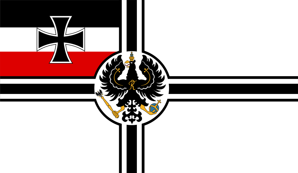
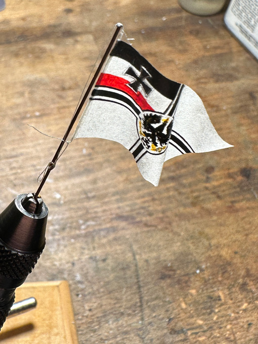
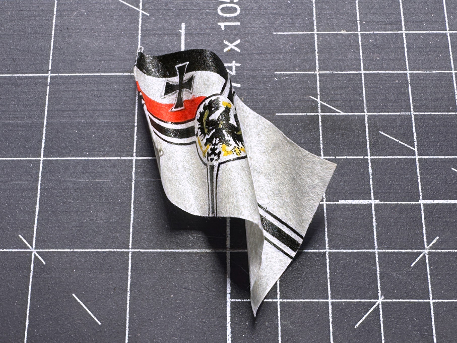
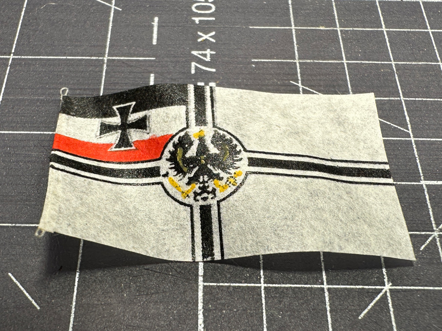
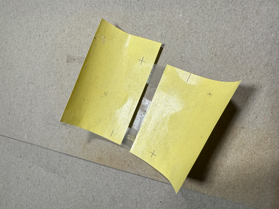
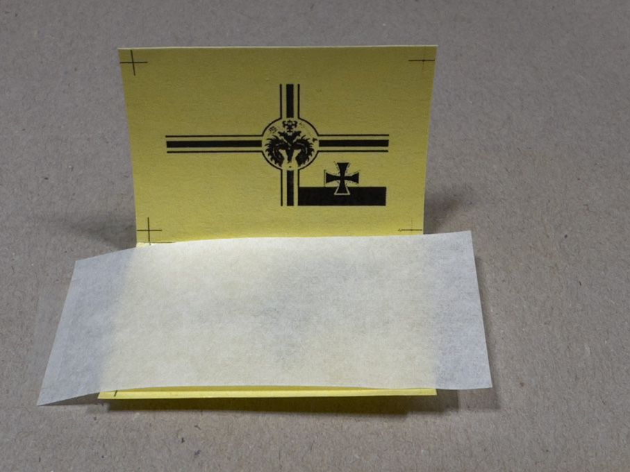
Once again, Thank You for your kind comments ! Again, real life including (business) travels got in the way of progress on this project. In addition, while I was having dinner in a restaurant together with colleagues, suddenly some ‘floaters’ appeared in one eye. I went immediately to the eye-doctor, who checked my eyes thoroughly. Luckily the floaters are harmless, but annoying signs of age. No retina-detachment or something else serious. Apparently, they can spontaneously disappear or the brain sort of ignores them after a while – keep fingers crossed. For the moment they are quite bothering, when working on really small things … so on to the ensign. ************************************ The Imperial German Navy Ensign This ensign was first conceived for the navy of the North-German Alliance (Norddeutscher Bund) in 1867, bringing together the colours of the dominant powers, namely Prussia (black-white) and the Hanseatic City States, Hamburg, Bremen und Lübeck (red-white). The design obviously was inspired by the British White Ensign and makes reference to various medieval symbols, such as the cross of the Teutonic Order, and the more recent Iron Cross from the Napoleonic War. After the proclamation of the 2nd Empire on 18 January 1871, this ensign became also the ensign of the Imperial German Navy and remained it until the end of the Empire in 1919. There have been, however, some smaller modifications over the years, thus the eagle was somewhat modified and in 1902 the arms of the cross were made heavier in order to avoid confusion at distance with the White Ensign of the Royal Navy. Overall, it is rather complex design to reproduce purely manually. First, I had to find a correct image for the ensign, as it looked in about 1878 and was lucky, as the Internet furnished a digital image of sufficient size and resolution. The idea was to print it on both sides of very thin paper (the kind that was used in the old days for carbon copies on type-writer, of which I kept a small supply). Such paper, however, does not feed well through the laser-printer and aligning for double-sided printing is practically impossible. Therefore, I resorted to so-called transfer-sheets. These are a kind of waxed paper that is used to transfer laser-printouts to T-shirts, mugs and such things. Laser-printer toner is basically carbon-black mixed with some plastics powder. It can be remelted with a heat-source, such as an ironing-iron and thus transferred to another substrate. I also experimented with overhead-sheets, but the results were not as good. Printing layout for the ensign (as it would appear on the transfer sheet) In a first step, the red stripe in the flag was eliminated from the image in Photoshop, as it would print grey otherwise. The ensign was then scaled to the right size on the basis of some trial-and-error, as the laser-printer prints a few percent undersize. I then added reference marks some distance from the image and duplicated this for mirroring. Several of these left-right-pairs were arranged on an A4-sheet and then printed onto the transfer-sheet using the highest quality print setting. Preparing the pouch for double-sided toner-transfer to the ensign-blank Using the best matching pair, I made a small pouch (as you would do for the masks, when producing photo-etched parts), aligning the images against each other for a perfect match on an illuminated board (they can be bought for a few €/£/US$ on ebay et al. and are powered through a USB-charger). An oversized strip of the thin paper was slipped in between and everything taped down onto a piece of thick cardboard. I pressed down an ironing-iron set to the lowest temperature onto the package, which made the toner firmly stick to the paper and no residues left on the transfer-paper. And voilà, a double-sided printed flag with a very detailed eagle etc. The toner is (almost) completely transferred to the ensign-blank In the next step the missing red stripe was added using red acrylic paint. I also added colour to the legs and beak of the Imperial Eagle, to the Imperial Insignia and the crown using yellow-ochre acrylic paint. If one has a colour laser-printer this step would not be necessary. The flag was cut out exactly to size, except for the rear, where it was left a tad longer to provide for a hollow ‘seam’ into which a thread with two loops at the end was laid The seam was glued down with some diluted white glue. This area also needed a bit of touch-up afterwards with black acrylic paint. The ensign before adding the colours Draping the flag is best done or least pre-arranged on the flag-staff. The paper was slightly wetted and the flag laid into diagonal folds in alternate directions. Toothpicks ensured that they became folds and not creases, which would be unnatural. Such a large ensign (2.9 m x 4.96 m) would fully unfold only in a moderate breeze and not in the light wind assumed in the scenic setting. So it flaps lazily in the wind, which I tried to reproduce. The completed ensign To the thus prepared ensign the halliard was attached as a loop. This loop was taken over the top of the flag-staff and a tiny laser-cut paper disc glued on as truck. There was no way to cross-drill the staff for the halliard. The halliard was belayed on the clamp. With this the assembly is ready for installation on the boat. But I will not hoist the ensign before the crew is on board. The recruitment process is still on-going … Ensign wetted and shaped Sorry, this was a rather lengthy essay on just and ensign, but the idea was to describe in detail, how to arrive on a reasonably realistic looking flag at such as small scale. The ensign attached to the flagstaff To be continued ....
- 873 replies
-
- 17
-
-
-
-
I have seen historic and contemporary films on YouTube that show the use of English Wheels and there may be one or two that show the construction of shop-made ones. To be honest I don't really see a need for such a gadget in ship-model building. In the automotive sector they are used to reproduce complex and tightly curved panels with beads or similar features. If you use single copper-plates or even whole strakes in most cases no particular shaping apart from pushing it snug against the wooden hull would be needed. In the worst case you could gently rub on it with a round wooden dowel or something like this on a soft and thick cardboard. In boat-building the vertical iron panels for so-called Francis-patent boats were hammered to shape over wooden formers. The same later in the early years of the car industry, before mass-production.
-
How does the Maxima Chameleon fishing line look like, is this a monofilament?
-
Thanks, Kurt, these are interesting insights into the operation of such tow-boats. Of course, if these flanking rudders can move, they make perfect sense, when going backward. This would be a classical application for Schottel-props, but I gather they may be too delicate for the shallow rivers full of debris. There is also a limit to the amount of HP they can bring into the water. Turnable pods with Kort-nozzles would obviate the need for all those rudders, but again debris might be a problem and the shallow draught needed. In the early 20th century for working on shallow (central and eastern) European rivers systems, where the props worked in half-tunnels were developed. Some tow-boats also used early forms of water-jet propulsion to aid maneuvering and turning in tight bends.
-
Greg, what do you mean by 'dernier line'? Dernier normally is a measure for the fineness of a thread (1 den = 1 g per 9000 metre) and was also used to classify ladies' stockings and pantyhoses. There are other systems, such as the tex. I am not a great fan of monofilament, as it tends to be relatively springy and, thus, knots tend to unravel, unless immediately secured with some varnish. Some time ago, I became aware of this high-end Japanese fishing line. It's braided, available in 'steel-gray' and down to diameters of 0.06 mm: https://fish.shimano.com/en-GB/product/line/braided/a155f00000c5ijoqa3.html. Quite pricey. I have not tried it myself, because I didn't have a need for 'wire-rope', which it might simulate quite well.
-
BTW, talking about toolmaker's buttons: I learned about them about 25 years ago, when I purchased from Lindsay Publications (now sadly defunct) a bunch of reprints of early 20th century machinist textbooks and the likes. Among these was JONES, F.D. (1915): Modern Toolmaking Methods.- 309 p., (Industrial Press, reprint 1998 by Lindsay Publications Inc., Bradley IL). Just checked on archive.org and one can now download a copy from there: https://archive.org/details/moderntoolmakingmethodsbyfranklind.jones.
-
My personal choice would be probably to varnish, though this is not very naturalistic. Just for aesthetics sake.
-
I have a separate hard-drive for backing up everything (as I also use the computer for work) around once a month and I only remove images from the telephone, once I have copies on two independent devices ... I was wondering about these rudders in front of the Kort-nozzles: do they move? If not, the boat would be quite sluggish to turn, I could imagine. And: oh, yes, the project is coming on nicely !
-
OUTSTANDING Mini Drill
wefalck replied to Bill Jackson's topic in Modeling tools and Workshop Equipment
That's a bit of thread drift now, but for really delicate work I use a watchmakers archimedean drill that requires both hands, as it does not have a return spring. I can precisely control the pressure needed/permissible (with tiny drills). Of course, the workpiece has to be fixed (some 'cello-type' suffices often), but this is good practice anyway. Mine can clamp drills down to 0.1 mm diameter. -
The contrast between brass and mahagony is always apealing, but I gather, beying 'under water' it will all be painted? Would be a pity for such lovely craftmanship to disappear under paint.
-
Looks worse than rigging a miniature ship model ...
-
P.S. just asked the colleague from which manufacturers his figures came ... here his answer: The figures were from - Scale 75 - Altores Studio - Romeo Models - Pegaso Models - Mercury Models - Revolution Miniatures So you have to check on the WWW what is available currently.
-
Talking about other people's projects: there is German colleague, I just remembered, who build a Viking-ship (the HAVHINGSTEN after one of the replicas after the Roskilde finds) in 1:25 scale and he had a whole boatload of 'Vikings' (or what he declared to be such). Not sure, whether you can see this without registering: https://www.segelschiffsmodellbau.com/t6718f20-Havhingsten-fra-Glendalough-21.html. He did a really good job in painting those figures.