rcweir
-
Posts
185 -
Joined
-
Last visited
Content Type
Profiles
Forums
Gallery
Events
Everything posted by rcweir
-
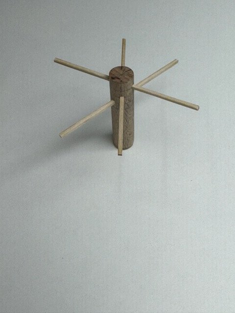
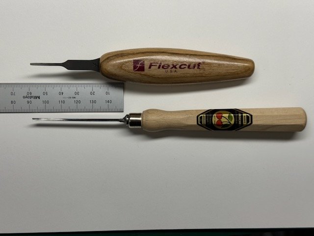
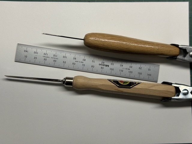
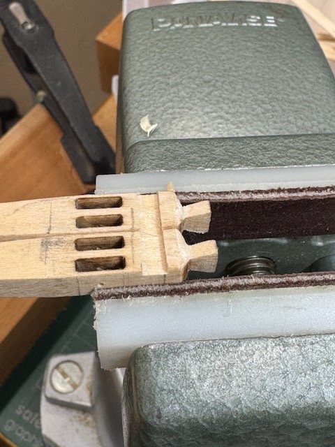
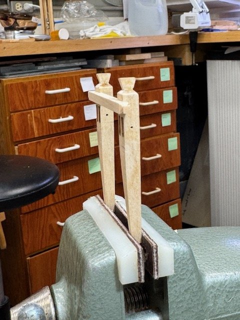
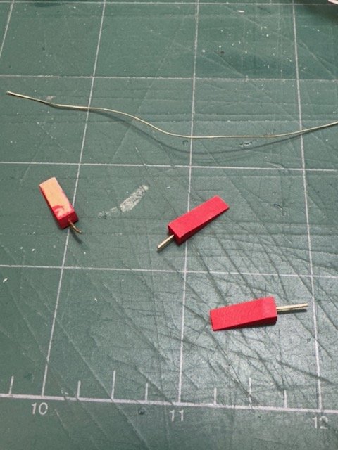
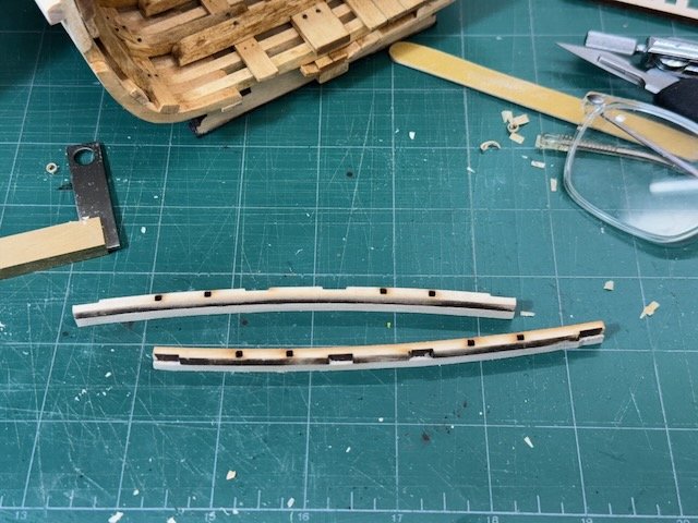
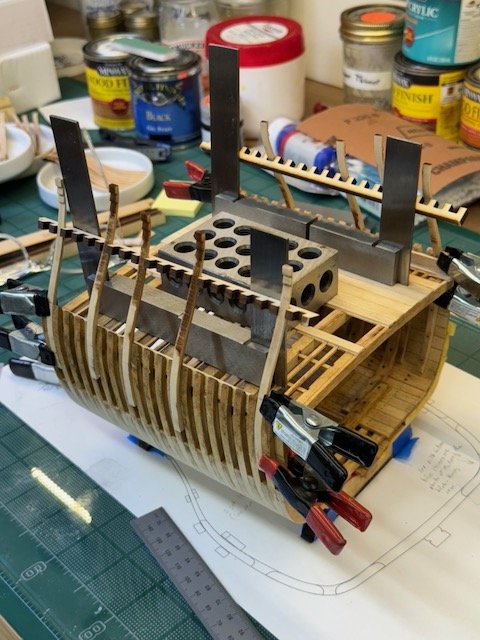
 This post is more about chisels than the model. The capstan requires 1.5mm square through mortises for the bars and I took that requirement as an opportunity to improve my tool set with some high quality itty-bitty chisels. In my chisel search I didn't find any practical reviews and few useful images, which is why I'm posting this. For the last several years I've used a set from Micromark (https://micromark.com/products/premier-elite-10-piece-micro-chisel-set?srsltid=AfmBOoo25HTv42qIr3vrm2I6f-pPAJdfx_ZCUUQOsFwwSeSSKkIMR4j5). It's easy to complain about these chisels, but they served me pretty well to the extent they could. The handles are good and they fit in my hand well, and there's a great variety of sizes at the very small end of the spectrum. And I think they are priced reasonably for what they provide. In fact, I don't know of any other source for chisels narrower than ~1.5mm. But, ultimately, they don't fit the bill for a genuine micro equivalent of a real bench chisel. A bench chisel has to take an edge, of course, but there's more: its back must be flat and its sides must be parallel. Nobody's chisel, regardless of size, comes from the factory perfectly tuned, but the potential has to be there and it isn't with my old set. From some searching on MSW and a little googling, my candidates for replacement were Kirschen's Two Cherries 1.5 mm chisel (https://twocherriesusa.com/product/micro-carving-tool-straight-chisel-octagonal-hornbeam-handle/) and the Flexcut 1.5 straight chisel (https://www.flexcut.com/home/product/mt11-116-1-5mm-micro-chisel?srsltid=AfmBOopeJrL74HjjF7cISoSlRGmPjaG7DdC1aEgpLCbbR6liTG1RayQW). I didn't see anyone other than Micromark offering smaller sizes, but as it happened 1.5mm was the right size for my current need, so I ordered the Kirschen 1.5 mm ($60.00, free shipping) and the Flexcut 1.5 mm 6 chisel set ($104 from Amazon https://www.amazon.com/dp/B016DBO1TK?ref=ppx_yo2ov_dt_b_fed_asin_title&th=1). Which may seem extravagant, but I figured the Flexcut set would prove useful and that one or the other of the two 1.5 mm straight chisels would be a good candidate to grind down to 1.0 mm, which is another size I think I have to have. Both arrived quickly. Pictures below. These were taken after I'd done some tweaking on them, which is why you can see some honing marks. The Kirschen's bevel is 25 degrees and the blade is 1.7 mm wide. The blade length is 5.3 cm and the width is constant. The handle is 1.5 cm diameter x 11 cm. It feels good and, since it's octagonal, it won't roll around on the bench. The blade bottom is flat (and can be made flatter when it's tuned up). One thing I don't like is that the blade tapers vertically from 1.5 mm at the top of the bevel to 2.8 mm at the back end. That means it can only fit about 3/4 cm into a square mortise. Most of the time, though, the extra strength that the taper provides will not interfere with my use. All in all, I think I'll get plenty of use from this chisel and I am sure that long blade will often be an important feature. The Flexcut's bevel is 27 degrees, and its blade was the same 1.7 mm as the Kirschen. Blade length is a short 1.7 cm and it tapers in the horizontal plane from 1.7 to about 2 mm. I definitely object to that horizontal taper. (What are they thinking to do that?) The vertical thickness is a steady 1.1 mm from the top of the bevel back to the handle. The handle looks like a sausage and I did not expect to like it. But I found this chisel surprisingly pleasant to hold and work with. Working in close, with the chisel in one hand guided by fingers near the end of the blade, everything about it is comfortable and secure. The ovoid cross section of that sausage means that it's easy to keep track of the blade's angle. I've already ground the blade down to about 1.3mm wide and my intention is to take it to 1.0 mm and make the sides parallel. I will get a second Flexcut, grind it to an actual 1.5 mm width and also make its sides parallel. I'll conclude with a couple of pictures of the capstan piece that has mortises made from these chisels. And that's all for now. Thanks for looking, and I hope this information proves useful to some of you. Bob
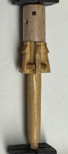
- 76 replies
-
- 5
-

-
- Pinas
- kolderstok
- (and 2 more)
-
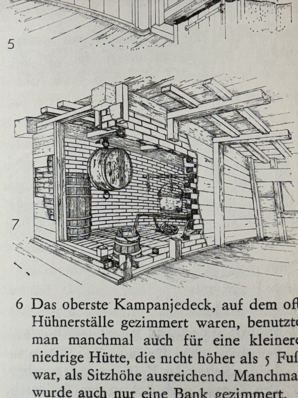
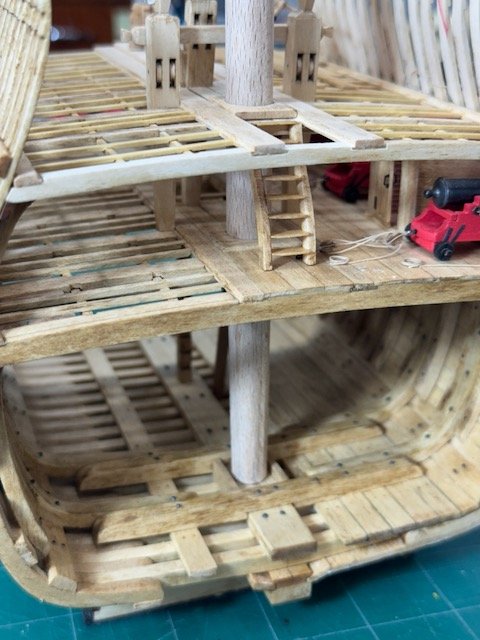
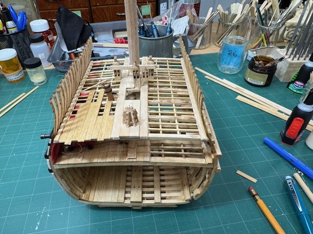
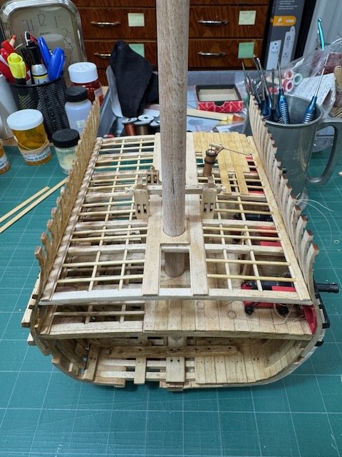
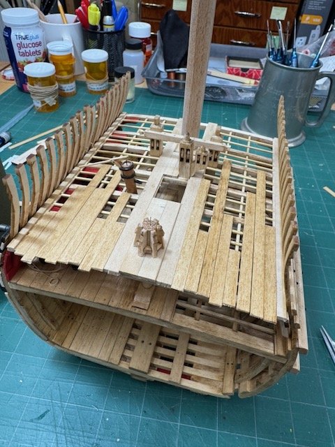
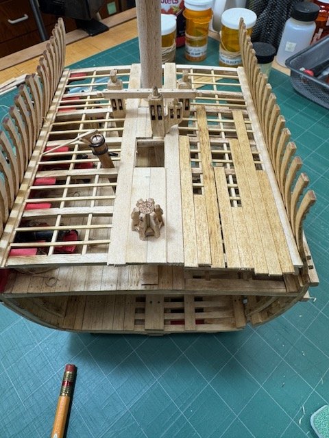
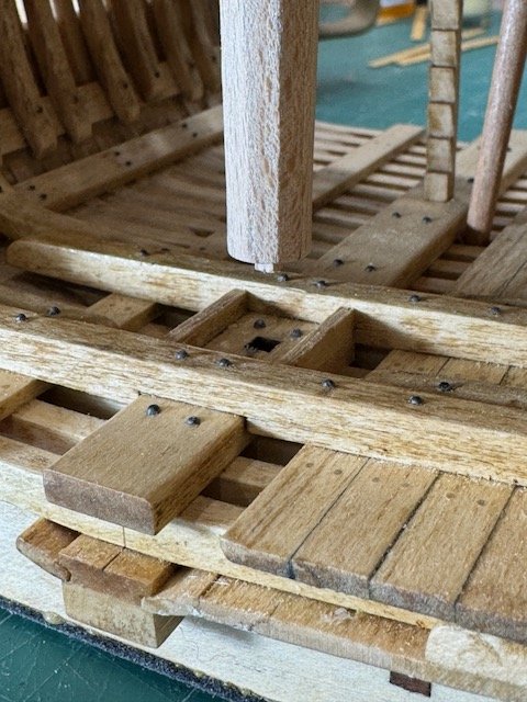
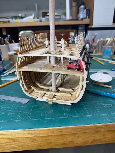
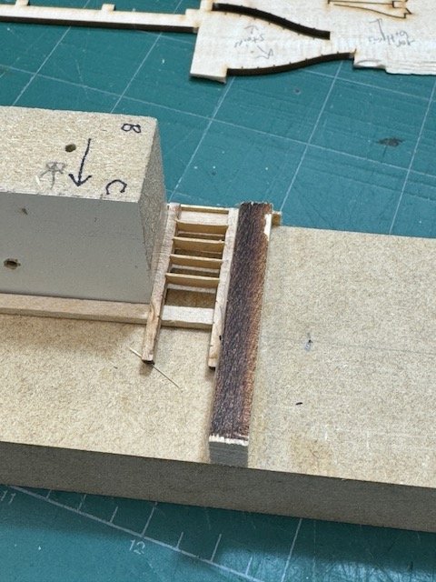
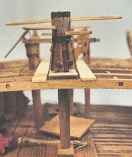
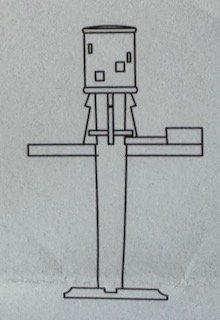
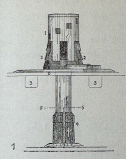
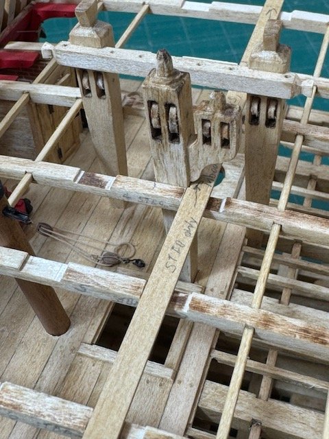
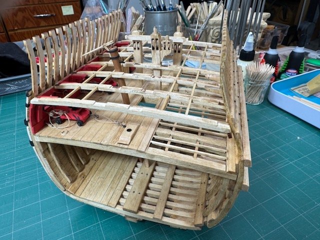
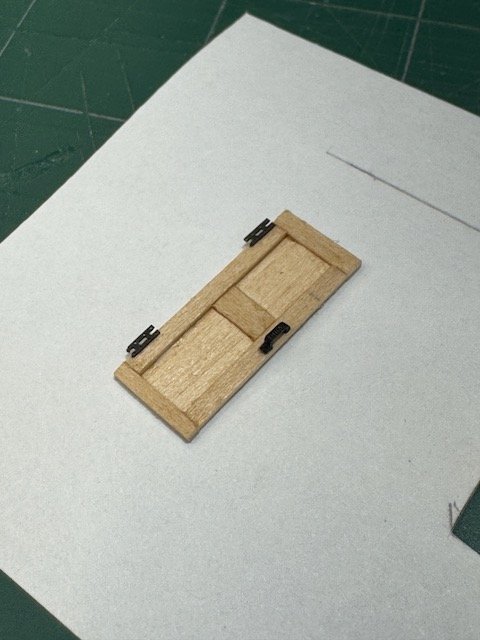
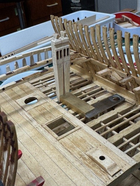
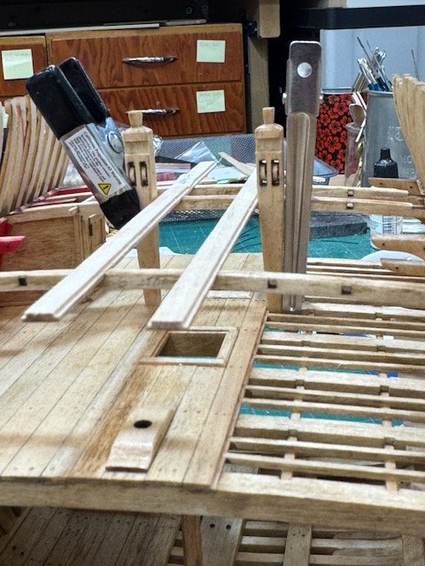
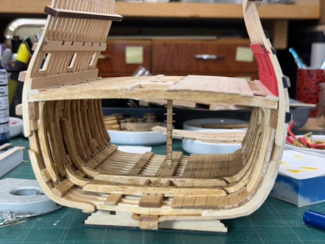
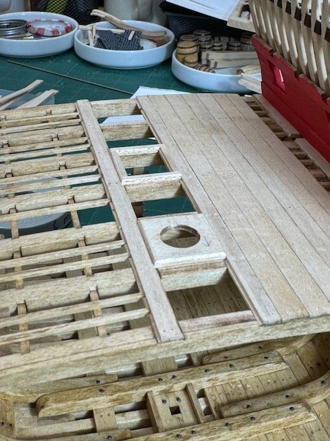
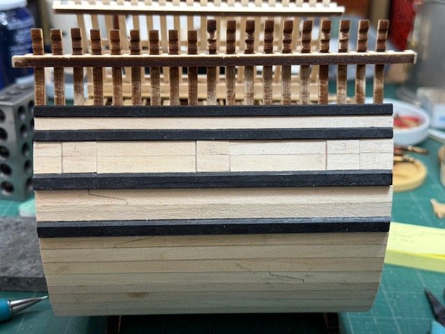
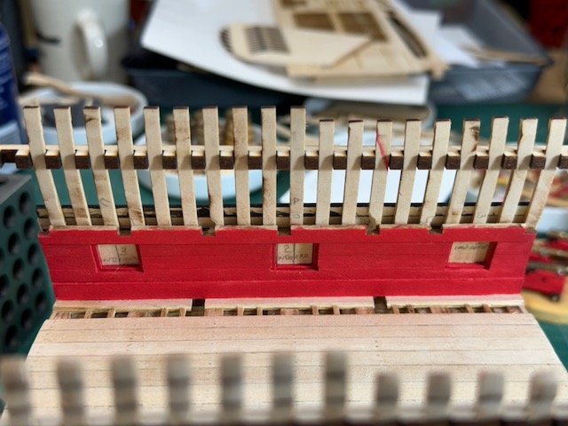
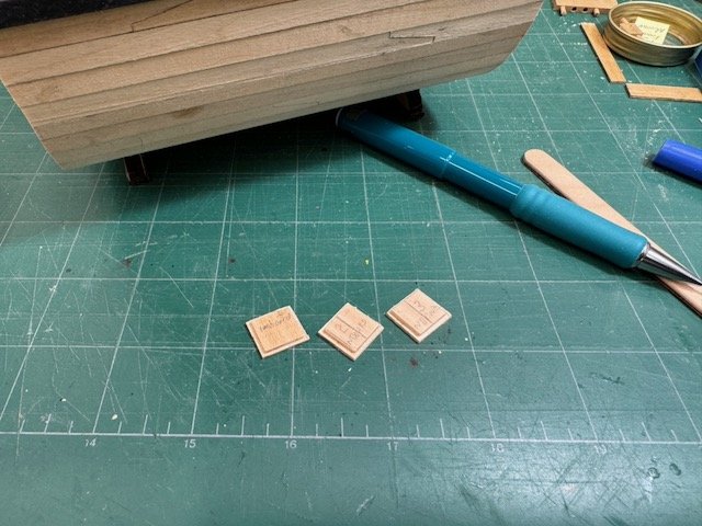
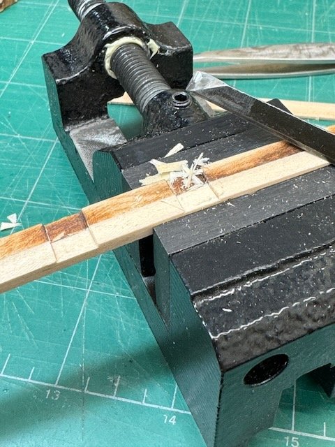
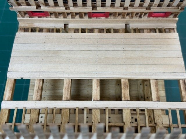
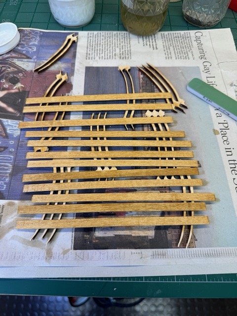
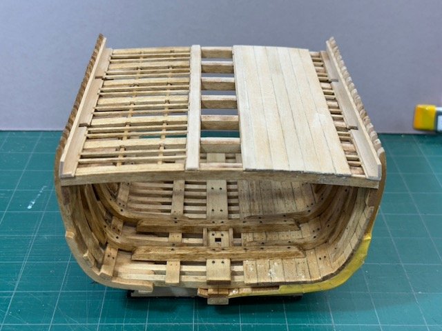
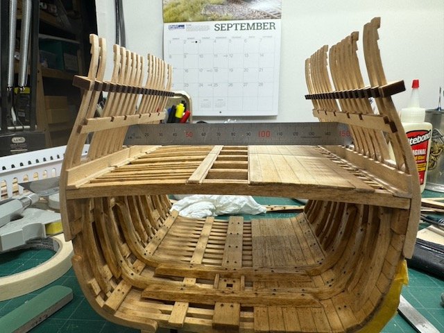
I've had a productive weekend so far, working on various details of the upper deck. First, though it's not installed yet, is the staircase (or slanted ladder, if you will) from the lower to upper deck. It wasn't hard to assemble, but I shaved the treads down to .5 mm (about 1/64"), so assembly was somewhat delicate. Once glued up it has proven to be surprisingly sturdy. Next is the capstan. I still need to make the upper half of the barrel, but the spindle, lower half of the barrel and its platform are all done. Dutch (and Swedish) capstans of the 17th century seem to use two basic designs for the portion above deck. The first kind is a simple cylinder. The capstan illustrations from the Vasa in Fred Hocker's "Vasa", a nice drawing in Herman Ketting's "Prins Willem", and the Batavia plans all show this sort. The Batavia's dimensions are roughly 4' high and 2' in diameter, with the diameter constant top to bottom. The other kind has two cylinders of differing diameters, with the larger on top and smaller underneath. Holes for the bars are in the upper portion and the line being worked is wrapped around the lower. The two-diameter style is what the kit calls for, and I've also seen that kind on plans that are part of Ab Hoving's "17th Century Dutch Merchant Ships". In both kinds of capstans the bar holes spiral down the barrel, so that successive bars aren't the same height above the deck. I am making my capstan in the second style, as the kit calls for. The lower portion of mine is visible on the near end of the deck in the next photos (I haven't made the upper half yet). But now I will come to the point. The kit's capstan design has battens on the upper barrel which spiral down on the same curve as the bar holes. The few references that I have don't show that kind of decorative(?) detail and I'm dubious that I can add it in way that looks good. So, at the moment, I am inclined to skip the spiralling battens. I think I will make a sample and see how it comes out, knowing that my references give me the leeway of taking an easier path. Here are small photos of the three variants I'm talking about. Left to right they are from Ketting, p. 51; Hoving/Emke, Sheet 4 of Pinas Witsen plans; and the kit instructions. In my previous post, #60 from 14 April, I mentioned the possibility of not planking the starboard side of the upper deck as called for in the instructions. Yesterday that expanse of unplanked surface was looking pretty bare, so I came up with the idea of planking just the after 1/3 of the deck. The next three photos show the model looking from aft with planks laid on the after 1/3 of (a) the starboard side, (b) both sides, and (c) the port side. (Remember, the instructions say fully plank starboard.) My vote is for (c) - that layout satisfies my desire for consistency by keeping the port side more finished, yet doesn't significantly obscure one's view of the lower deck when seen from the forward end of the model. The last item for this report is just that I've shaped the lower portion of the mainmast, including the heel tenon. Simple as it is, I made a great advance with my Proxxon lathe doing this work, because I made the taper with regular carving tools rather than sandpaper. Using a gouge to reduce diameter is much, much faster than sanding and a heck of a lot cleaner, since the gouge produces (tiny) chips rather than dust. I found that the Proxxon's toolrest was stable, the chuck and tailstock held the work firmly, and there was no vibration. The lathe was securely fastened to the bench, of course. It was also easy to make the lower section octagonal (by hand) with the mast in the lathe. This experience will give me more confidence in using that lathe for future work. Finally, I'll add one photo taken from the bow that shows what the model will look like with the port side of the upper deck planked on the after portion. I have started thinking about the display base, but have not made firm decisions yet. I think, though, that it has to have a cover which I'll make myself out of plexiglass. That's all for now. Thanks for looking! Bob
- 76 replies
-
- 7
-
-
- Pinas
- kolderstok
- (and 2 more)
-
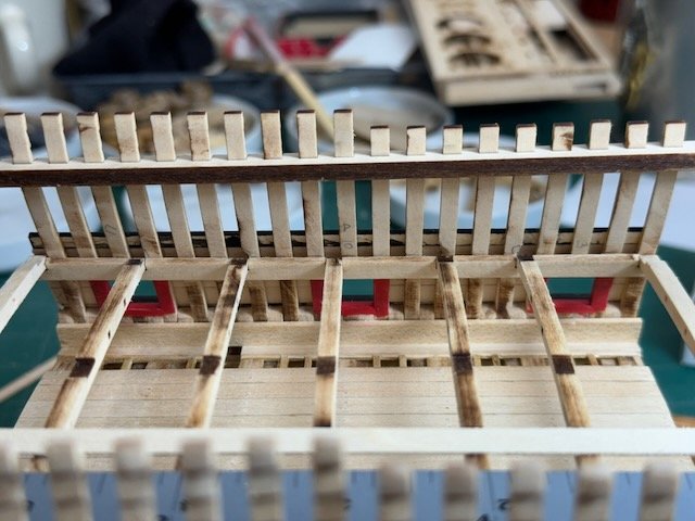
Not a lot to report since my last entry. Once the pump was in, I was able to install the remaining upper deck beams. Since my two end beams don't have through-mortises for the carlings, they had to be installed along with the beams. Next was to install the ledges, the small athwartship beams that rest on the carlings and mortise into the strakes. The end of each ledge has to be mortised into the edge of its binding and nibbing strake, plus I had to add shallow mortises where they lap the carlings in order to have the ledge tops in the same plane as the beam tops. The ledges are only 1mm square, and it's finicky work to fit them. So, I made mine out of Alaska Yellow Cedar rather than use the kit-supplied basswood: AYC is easier to work with at these tiny sizes. I don't think the color difference is very noticeable. The kit calls for a full lower mainmast all the way up to the top, and including shrouds. But I'm just going to install a stub mainmast. I think that will result in a model that's more visually balanced and will keep the viewer's eyes focussed on the hull details. And last night it occurred to me that maybe I should plank less of the upper deck. The center area between the two binding strakes will acquire the capstan, mast, cargo hatch and a ladderway hatch. But there's almost nothing more to be added to that deck outboard of those central strakes. The instructions call for planking the opposite side of the upper deck than the lower, i.e. starboard rather than port, which leaves the deck above the cannon and galley open to view. So the argument for planking isn't one of consistency for its own sake. And I think exposing more of the upper deck framing adds visual interest. But I would be happy to hear other views - I'm far from committed one way or the other right now. Thanks for looking, Bob
- 76 replies
-
- 7
-
-
- Pinas
- kolderstok
- (and 2 more)
-
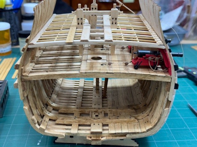
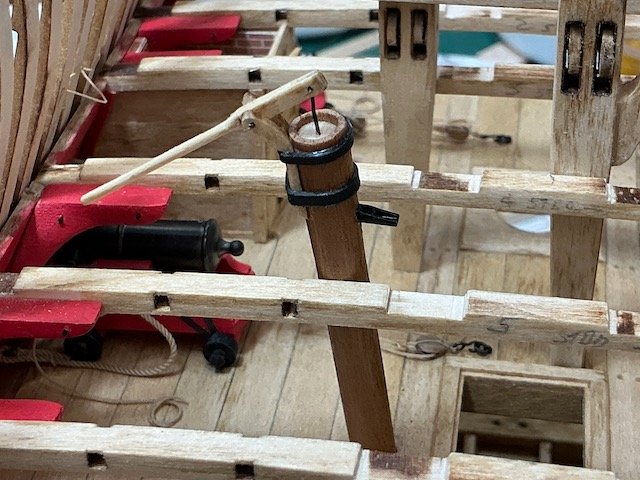
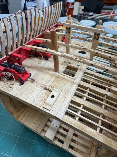
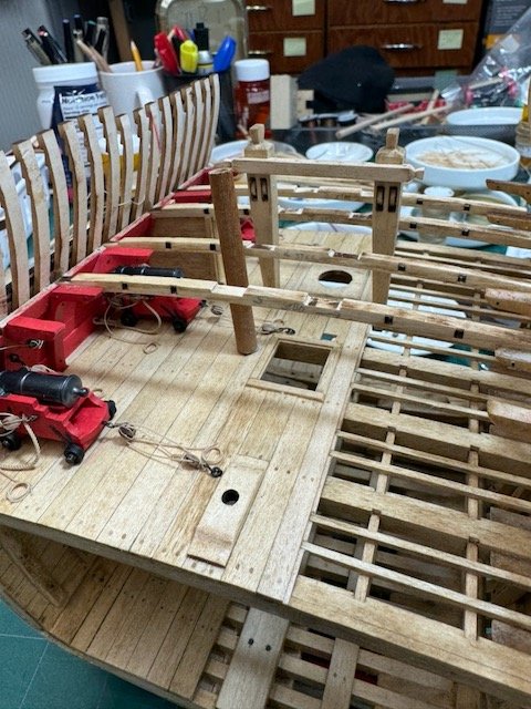
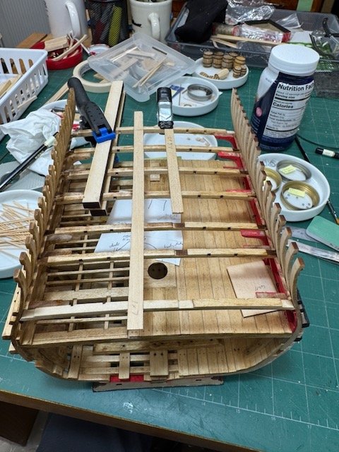
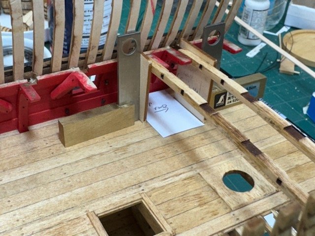
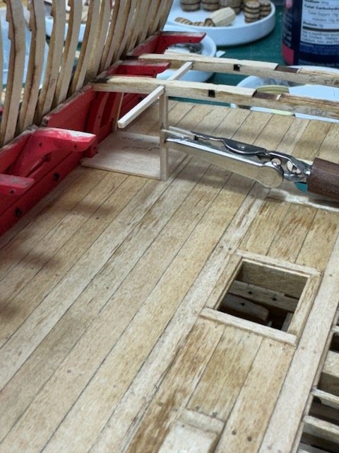
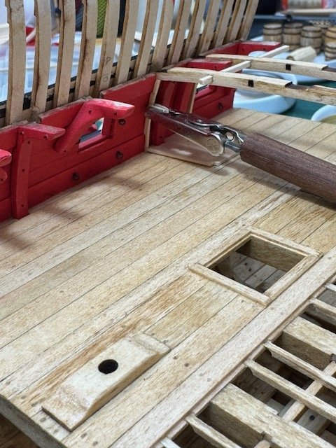
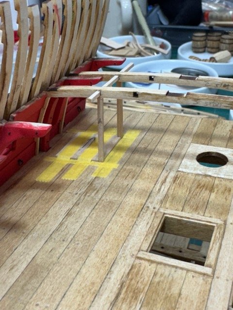
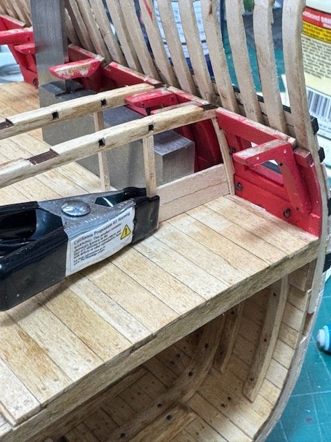
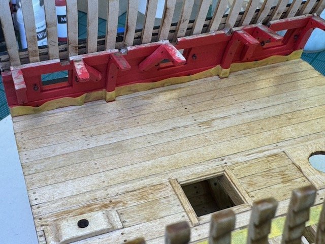
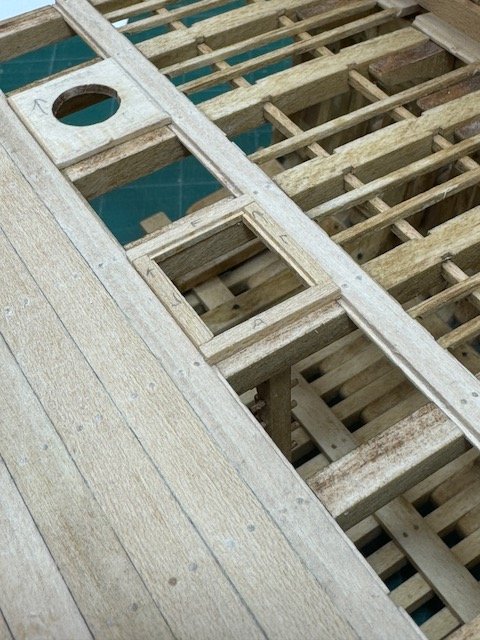
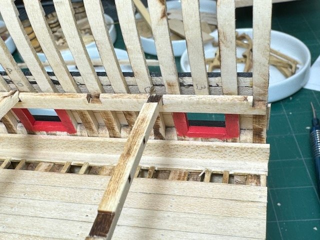
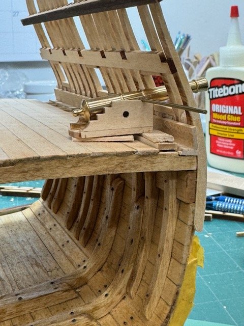
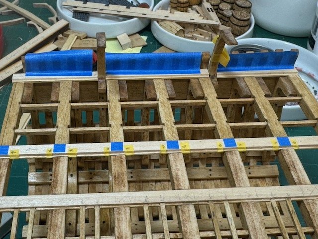
I've finished and installed the pump. Making it wasn't difficult, but locating and drilling the hole in the lower deck for it to pass through gave me some anxious moments. The pump sits (at a tilt) in the bilge, next to the keel. From the keel it passes through the lower deck at a point that avoids deck beam, carlings and ledges, then reaches up to the upper deck where it leans against a deck beam. In my first picture here you can see a stub mockup I used to help me find the right location to drill. In the second picture you can see the hole. Access was a little easier than it appears since the two upper deck beams in the photo aren't glued into place yet. I considered making a strainer basket for the pump, as shown on p. 48 of Herman Ketting's Prins Willem. (1981, Verlag Delius, Klasing & Co. It is profusely illustrated with wonderful sketches of all manner of fittings.) But I decided that it would be virtually impossible to see, so not worth the trouble to do. It worked out alright, thankfully . The pump was the last step to essentially complete work on the lower deck. From there I've moved on to installing the upper deck. As I did on the lower deck, I am building the underpinnings in a more prototype fashion than the instructions call for. The main points are that I don't want the viewer to know that the carlings pass all the way through the beams, and I want the ledges to be mortised into dados let into the sides of the binding and nibbing strakes. To hide the carling holes, the two end beams have to be modified. On the lower deck I made new faces for those beams. But the line between the original beam and my new face was more visible than I liked, so for the upper deck I've made entirely new end beams. Manufacturing new beams is very straightforward since there's there's a perfect template to work from. The complication that I didn't anticipate comes from the dado that I'm putting into the binding strakes. The three bitts that poke up from the lower deck all rest against the side of one or the other of the binding strakes, and to make that look good they have to make that contact at the top edge of the strake, and not the edge of that dado. This is a point that I didn't grasp until all of the bitts had been installed. To solve it, I widened the strakes from 7 to 9mm, and correspondingly widened the mortises in the beam tops which the strakes sit in. Visually, I expect that the result will look quite natural since the width of the strake tops will be the same as the 1x7mm regular deck planks. The next photo was taken as I was installing the carlings and end beams - there's a scrap piece to help with alignment sitting in the mortises where a binding strake will eventually go. And the final photo shows a narrow template piece that I'm using to locate exactly where to cut the dado off of the binding strakes to accommodate the bitts. Thanks for looking, Bob

- 76 replies
-
- 5
-
-
- Pinas
- kolderstok
- (and 2 more)
-
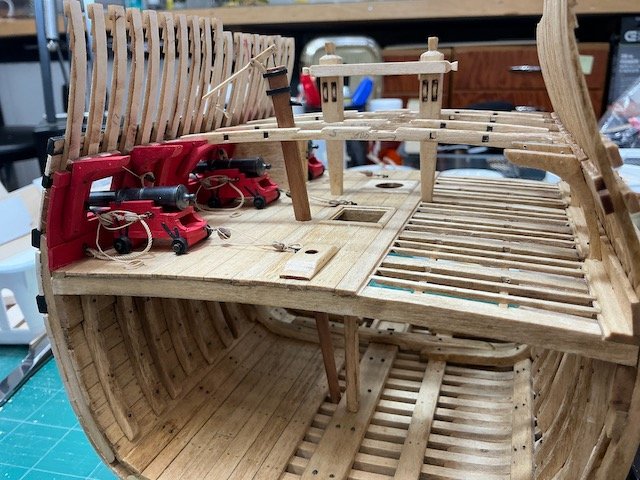
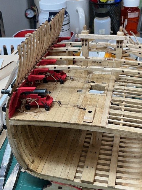
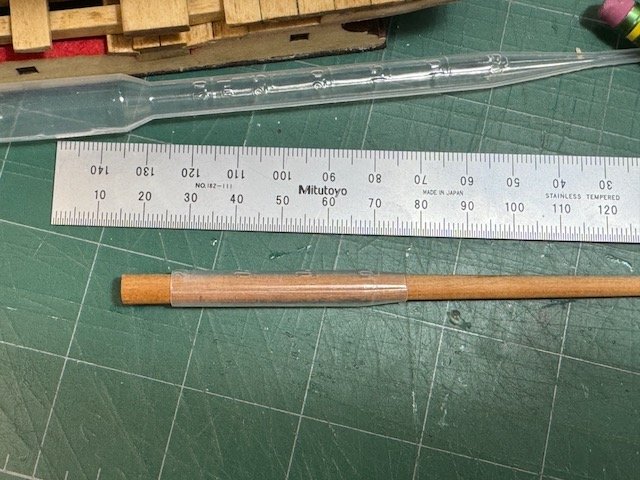
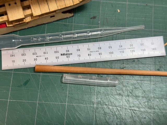
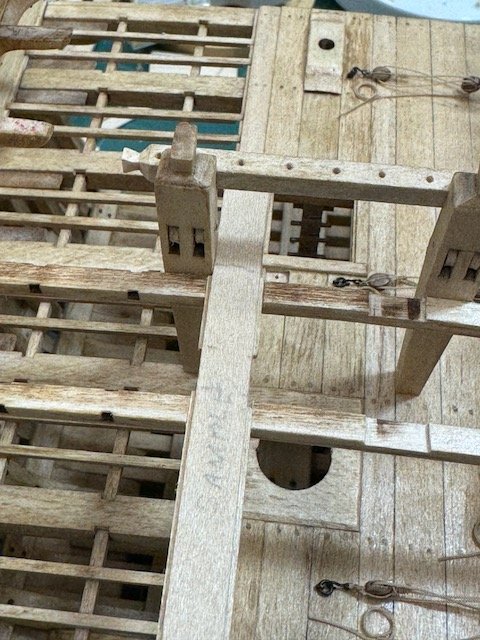
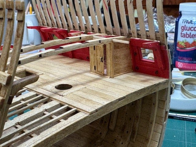
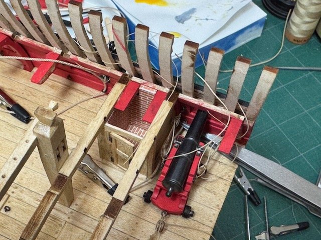
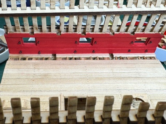
This will be a short update. I made some very casual-looking rope coils for the lines tending the guns and installed them, which you can see in some of the pictures in this post. The more important job was to figure out dimensions for the upper deck binding strakes and fabricate them. As on the lower deck, I'm deviating from the kit instructions by putting a rabbet on the 2mm thick binding strakes. This provides a proper support for the edge of the adjoining 1mm deck planks. Plus, the rabbet is also needed to show (something like) the proper joinery for the ledges, as was done on the lower deck. Anyhow, due to my failure to look carefully enough into the future when I installed the bitts, I positioned them in such a way that they weren't going to sit nicely alongside the binding strakes - there would be an awkward gap the width of that rabbet between the side of each knightshead and the visible top of the neighboring binding strake. Since it's much too late to move the knightsheads, I chose to widen the binding strakes by 2mm. As you can see in the first picture here, which uses a sample binding strake piece, the relationship between the knightsheads and the strakes now looks good. I had to mill two new strakes and I also had to widen the joints in the deck beams to handle the wider strakes, but neither task was difficult. Next on the list is to make the pump, which I haven't finished doing yet. The instructions call for the pump to pass through the upper deck on the port side and just forward of beam #4. I initially had no reason to question that location, but after thinking about it a while, some things cropped up. First of all, it must be just a simple typo when the instructions say "front side of beam #4" because the instruction pictures all show it aft. (Remember, there are no relevant formal plans for this kit.) But, as I looked closely at things and almost started drilling, I realized that the kit instructions did not install the middle cannon! Three cannons are supplied, and the instructions describe constructing and installing all three. But, in every photo I can find in the instructions, the middle port is empty and there is no gun. This is a big deal for the pump's location, because in my build, which has three cannons, a pump in the specified location would be right in the recoil path. That's a long story which has a simple solution - I'm moving my pump location back to the forward side of beam #5, where there's plenty of room. In the next two photos you can see in the first one a pump mock-up located as in the kit instructions, and the second shows approximately where mine will be. As I said, I'm still making the pump itself. Hopefully it will be available soon to show. One little trick I came up with to hold the tapered spar in my Proxxon lathe was to slide it into a section of a disposable liquid dropper. It holds and centers well in the lathe chuck and there's no marring of the piece. That's all for now. More soon, I hope. Bob
- 76 replies
-
- 7
-
-
- Pinas
- kolderstok
- (and 2 more)
-
Mini Table Saw recommendations
rcweir replied to captainscott's topic in Modeling tools and Workshop Equipment
One characteristic of a mini table saw which I don't see much discussed is setup time. Most of my trips to my Byrnes saw are to cut one or two pieces, and then head back to the bench to continue work. I'm perfectly fine with lengthy planning and setup for a large volume of similar cuts, or for something special. But the very common one- or two-cut rip or cross-cut (or both) jobs take an inordinate amount of time to prepare on that saw. Today, for example, all I wanted to do was crosscut a 1/16" piece of walnut. After disassembling and removing the Byrnes' rip fence (always a nuisance because the fit is so tight and a worry because of the loose bolts), then reconfiguring the miter gauge (another opportunity for loose bolts), I realized that I was going to have to swap out the saw blade. At that point I gave up, walked over to the big saw, slid its crosscut sled into place and made my cut: 60 seconds start to finish. But the Byrnes was really the better tool for the job. So, my main question is whether a Proxxon mini saw is quick to setup and reconfigure? Can you switch from rip to crosscut and back again in a few seconds? Are there loose fittings all over the place when changes are made? How long does it take to swap blades? Price is not my main concern: efficient flexibility of the tool is. Thanks, Bob -
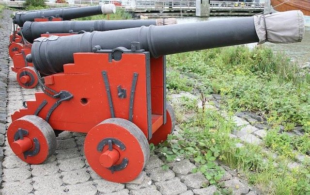
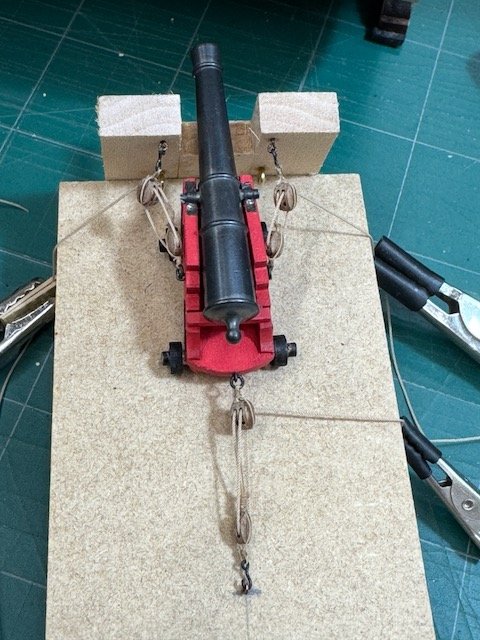
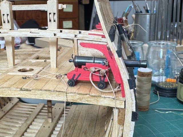
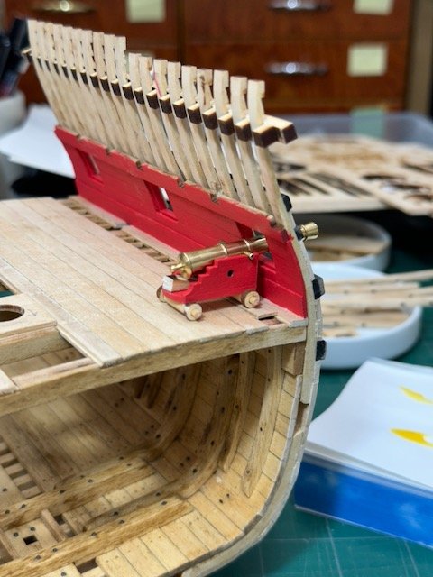
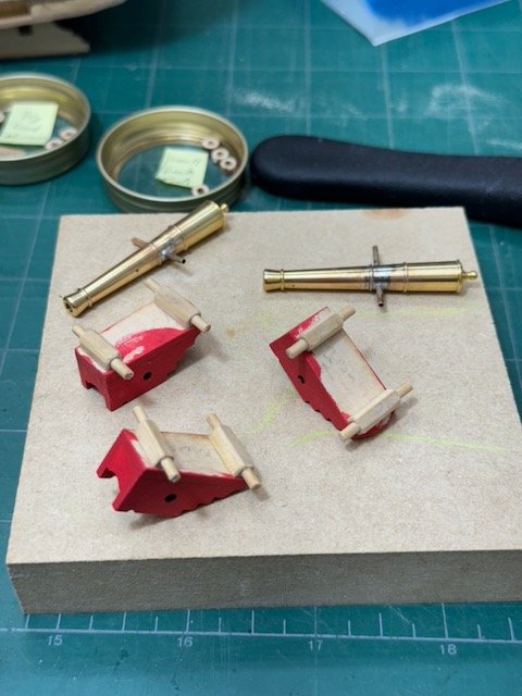
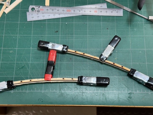
It has been a very long time since my last update. I have been busy, though, on the model as well as a couple of unrelated projects. Late last year I finished the galley. You'll see that I left the door ajar - there's not much in there to see: I couldn't decide what the cookpot ought to look like or exactly where to locate it, and so it will probably remain as it is now unless I have an inspiration which I can lower in from overhead. The hinges and door handle are from Syren. Next, I worked on the knightsheads for the upper deck. And then I started on the cannon, which is where the majority of my modeling time has been spent over the past three months. I made ringbolts for the bulkhead fittings, and hooks for the gun tackles. I'm using hooks not so much because it's prototype practice (I don't know if it is), but because the space for rigging is fiendishly tight and I thought I could probably do a better job if most of the rigging work was off the model. Hooks help make that possible. It was a worthwhile decision for practice making things like rings and hooks: there's no commercial source I know of for either that meets the size requirements here. The first picture below is one I downloaded of a cannon that's at the site of the Batavia reproduction ship in the Netherlands. I used it as a guide for how the various bits of ironwork ought to look. I won't go into the lengthy efforts learning how to seize the blocks with the hooks, rings, beckets and things. Anyway, once I finished the block preparations, I did the rigging on a gun station mock-up that gave me plenty of access to see that lines ran as they ought and nothing looked tangled. I didn't have a magic solution for moving the rigged assembly over to the model, but having run all the lines first did make it easier to get the tackles in their intended places on the model. The hooks and ringbolts worked out just fine and I don't think I could have done the job as neatly (though it's still far from perfect) if I'd tried to do it all in situ. I used the 4mm kit blocks, but with everything rigged up they look oversized to my eye. However, I'm not tempted to go back and try 3mm now; just something to think about for next time.
- 76 replies
-
- 8
-
-
- Pinas
- kolderstok
- (and 2 more)
-
Principles of Paper Models: Construction, Design, Thoughts by David M. Lukens is available only as a pdf. I have Version 0.56, 2019-04-03, copyright 2019. It is 162 pages long, with many color illustrations. The book (and some model plans) can be downloaded for free from Lukens' website at http://insanityunlimited.com/modelplans/. A voluntary contribution can be made via paypal or credit card - there are links for that, too, at his website. This is a primer on card modeling. It isn't aimed at ship modelers specifically, but there is a section on boat hulls. The whole book is beautifully illustrated with many clear, color photos and drawings. The first paragraph of the introduction gives a good idea of his goal with the book: If you are reading this, then you likely have an interest in model building of some manner or another. I will be approaching this set of topics from the standpoint of paper models (also known as card models). I hope this book ends up meeting your needs as a technical guide and one that propels you through many years of an enjoyable hobby. You never know, you may find a way to turn this hobby into a side business or career. That last part I am still trying to figure out and is a little bit more difficult. Overall, I want to present information to you and I hope it opens up new possibilities that you will enjoy and generates more ideas. And here's the Table of Contents (abbreviated to the top two levels, only): Table of Contents Forward Introduction History Basics of Building Choosing Your First Model Tools Paper Printing Cutting Scoring Folding Rolling Glue Markings Advanced Building Techniques Environmental Concerns Tools Sealing Scoring the Backside Slicing and Cutting Blade thickness Blade edges Blade angle Why edges matter Edge Coloring Laminating Building Square Structures Panel Layering Boat Hulls Glue Tabs vs. Strips Railings and Ladders Wirework Paper Moulding Filler Converting Scales Adding Durability Weathering Non-Paper Materials Design Toolset Presentation Glue Tabs Fitting to Page Design Concerns of Paper Using Non-Paper Materials Glue Joints Printed Detail Printed Detail and 3D Detail Project Definition and Scope Research Internal Structures Design Tricks Instructions Test Builds Publishing My Workflow Licensing Glossary This book gets a strong endorsement in Hoving's recent Dutch 17th Century Ship Models in Paper, but it took some effort to discover how to actually get hold of it. Once I did, and saw its high quality, I wanted to post something at MSW to make it easier for others to find. There's not much more that I can say other than it seems like a great resource, especially for someone like me who has never made a card model. Lukens writes clearly and the text has been well edited. The photos and drawings are profuse and of excellent quality. Bob
-
I use P&K Custom Acrylics. https://pkcustomacrylics.com/ They're located in Malden, Mass (a suburb of Boston) but claim to ship nationwide. I have not had them make me a box such as you describe, but what they've done for me is impeccable. Bob
-
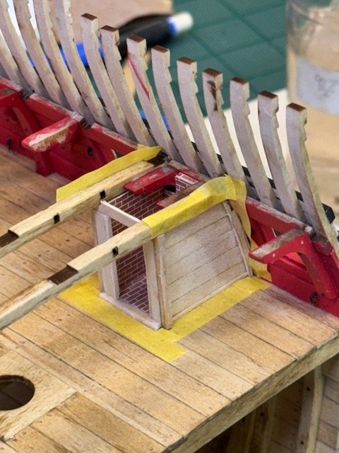
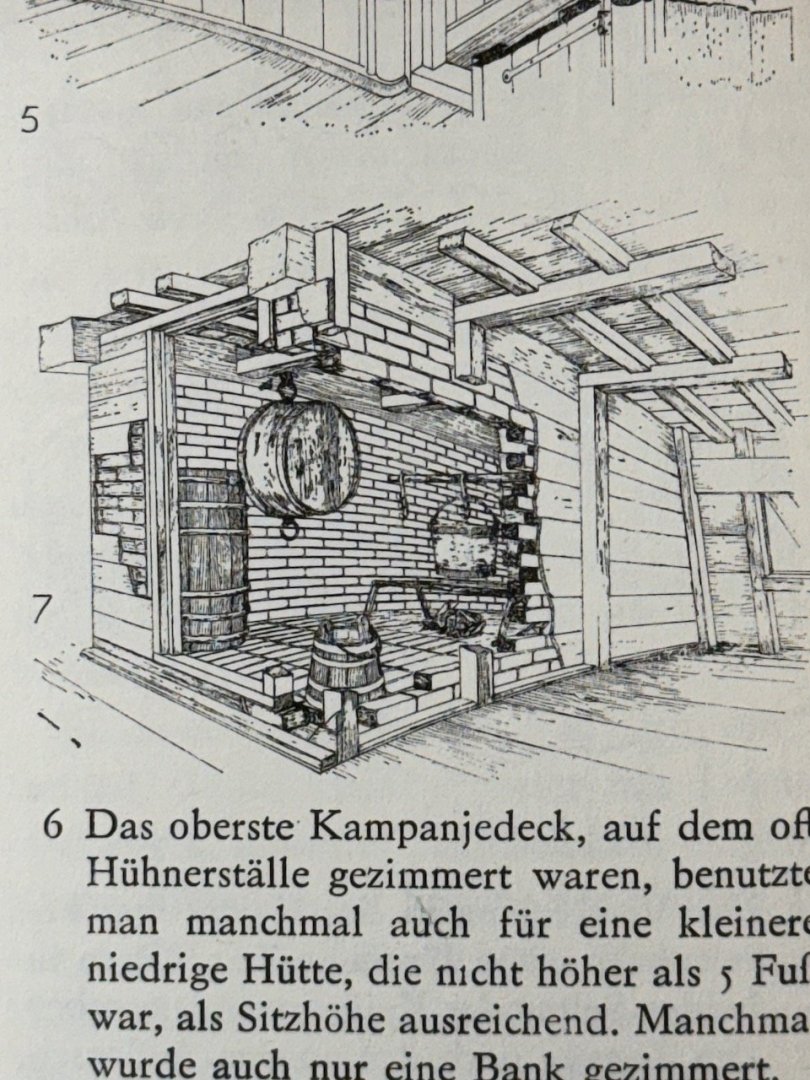
Last night I spent some time "walking" around the virtual Pinas that Ab Hoving mentioned on MSW a couple of years ago: That simulated pinas has a galley that looks identical to the one in the kit. Like the kit, the entire compartment is bricked with the exception of the overhead and the door. On the exterior, the compartment sides extend to the side of the ship. On the interior, all of the bricked bulkheads are vertical. Which implies that there is a void between the outboard brick and the side of the ship (due to tumblehome). In the overhead above the location of the fire, there's a black square object which I take to be a smoke hood leading to the chimney. I think this is enough for me to proceed with. I'll keep my slightly different floor plan, but otherwise brick up the interior as the kit and the pinas simulation indicate ought to be done. And I'll add that smoke hood, too.
- 76 replies
-
- 4
-
-
- Pinas
- kolderstok
- (and 2 more)
-
Thanks for those pics, Patrick. I think they show what is basically the kit design for the galley, but it doesn't quite work for my build. My gunport just forward of the galley is located one futtock farther aft, which I did (and at least one other builder has done) to make space for the gun and its hardware, i.e. ringbolts. What I lost doing that was space for the galley's bulkhead to extend forward of the #2 deck beam: no part of my galley can creep out past the forward edge of the beam. Faced with that limitation, as well as the discovery of Ketting, I'm trying to rethink the entire galley. Ketting's sketch illustrates a configuration very similar to mine: both fore and after bulkheads are under deck beams. My quandry right now is what the hidden, outboard, end of the galley looks like. Seems like it must be bricked, but unless I can find other references, I'll just have to make some guesses. And FYI, the deck above won't be planked over the galley, so what I end up with for a solution will be somewhat visible. (It's probably obvious, but puzzles like this are a large part of what I love about modeling, and this model in particular. This is a really delightful kit to work on!) Bob
- 76 replies
-
- 5
-

-
-
- Pinas
- kolderstok
- (and 2 more)
-
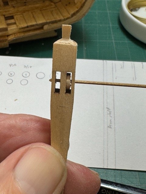
Here's a quick update, since I have a few spare minutes. First, I've been working on the knights heads that will hold up the mainmast bitts. The kit-supplied cross piece had mortises that were too large, so to get a tight fit I made a new one, and routed a 1mm mortise into the knightsheads (rather than the crosspiece). This is probably more authentic, but my main motivation was to make it easier (eventually) to go through the steps of first fitting each knightshead and then adding the crosspiece without too many degrees of freedom in the joint location. I made the mortises (second picture below) by gluing the two pieces together with PVA and then cutting them on my Byrnes saw. ... And the result was very satisfactory (this is just a dry fit for now): I sawed up 3 dozen 1mm x 1mm strips for ledgers, which I'm going to need for the upper deck supports.And then glued in upper deck frames #2 and #3 (the second and third from the front here). I'm currently working on constructing the galley. I've deviated from the kit design in a couple of ways, mostly to keep the forward most bulkhead away from the forward gun's rigging. I am using Ketting as my main reference for what a galley should look like, and following his lead on how the bulkheads are positioned under deck beams and the exterior horizontal planking. What you see in these photos is as far as I've gotten, and really as far as I have figured out where, exactly, I am going with it. One thing I don't know is what the historically proper treatment is for the outboard side of the galley compartment. The kit gives it a separate wall that doesn't touch the ship's side, and that does make sense if the whole space has to be bricked up. That's where things stand now. Thanks for looking! I will now go walk the dog. Bob
- 76 replies
-
- 6
-
-
- Pinas
- kolderstok
- (and 2 more)
-
Alcohol will dissolve shellac. That rule always applies, no matter how long the shellac has been down. But another rule (for furniture finishes) is that any finish can be applied on top of a wash coat of shellac. I'd suspect in this case that the shellac mixture was too thick; I use a 1/2 pound cut for wash coats, which means the shellac was mixed in the ratio of 1/2 pound of shellac flakes for each gallon of alcohol. That's contrasted with top coat cuts of 2-4 pounds or more. I don't know what pre-mixed cuts are like, but I would think they're much thicker than 1/2 pounds. The main reason for the wash coat (again, this is me speaking and not a finishing oracle) is a transition step between sanding and applying the finish. The wash coat will raise the grain, which can be sanded down with a fine grit, and then the top coat application will have a much reduced effect on the wood's smoothness. I would not expect that the wash coat of shellac is going to be any help unless one expects to lightly sand after it. (We were also taught that "sealing the wood" was impossible. Discussions along those lines instead used terms like "filling the pores" and "leveling the surface", because one goal for the finisher is a desired final surface quality.)
-
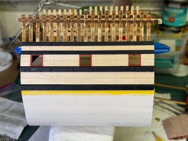
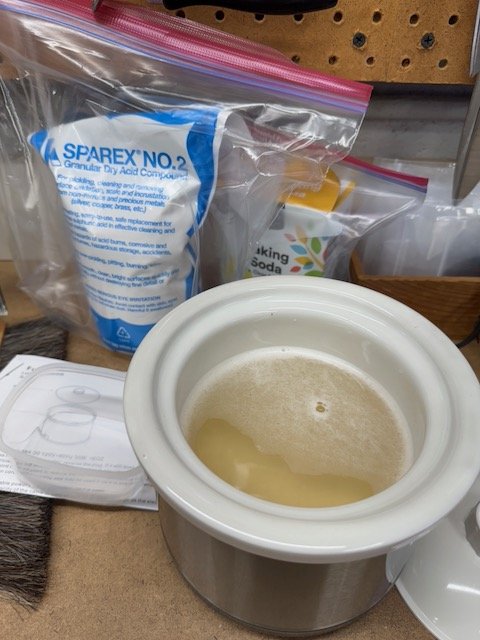
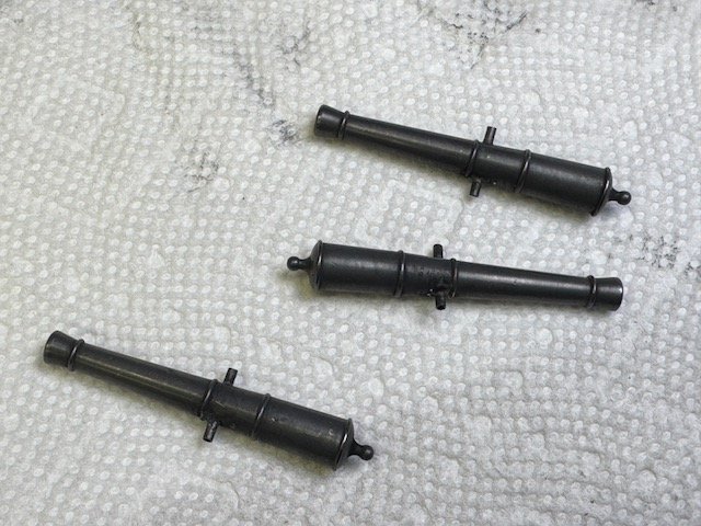
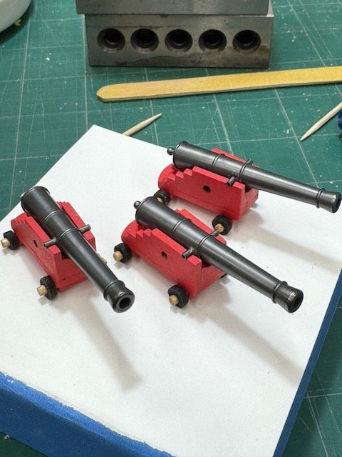
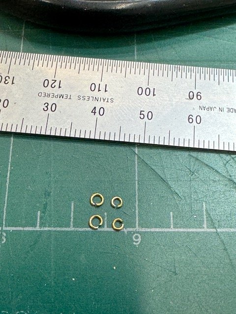
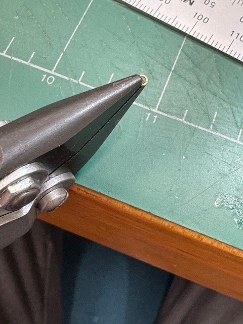
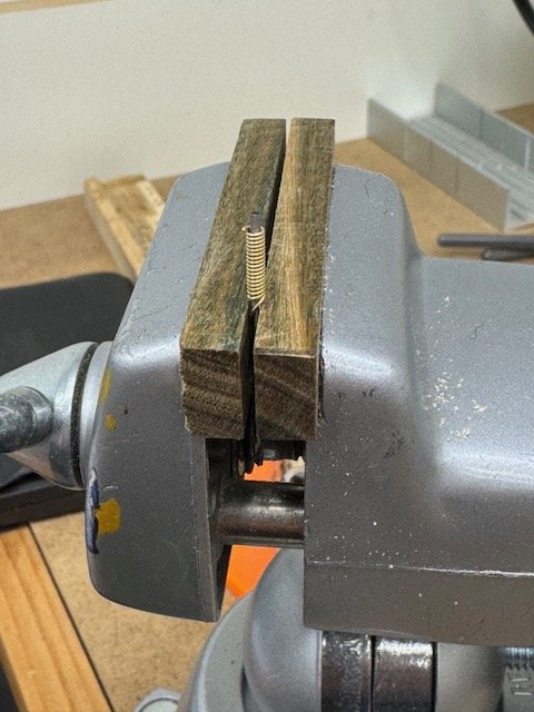
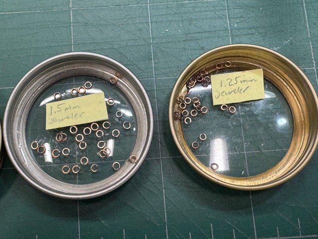
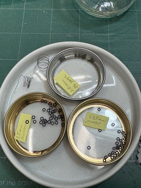
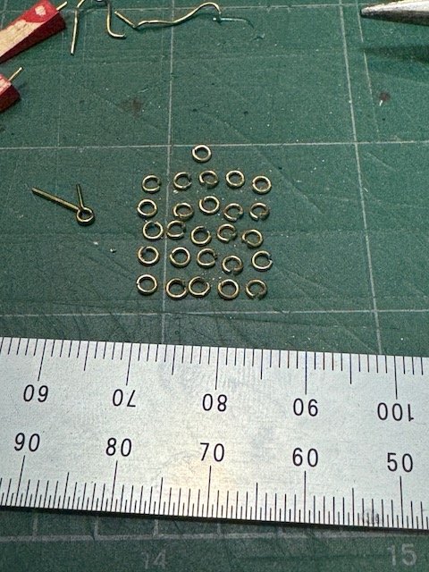
It's been a long time since my last post, but I have been working steadily, though there hasn't been too much to show for it. I painted the port (planked) side of the hull using the Kolderstok paints. I like those paints a lot, though I over-thinned the white on the lower hull so it took quite a few coats to get good coverage. Next, I had to blacken the cannon and this time I was determined to not cut corners and instead put the necessary effort into learning the steps required to get reliably good results. Fortunately there is this wonderful explanation by dvm27 on MSW describing his methods and equipment. I tried to do exactly what he did without any corner-cutting, and it worked out great. Here are photos of my pickle pot used in prepping the cannon, the colored cannon after treatment (with Birchwood Casey Brass Black), and the buffed-up final result. I know that an alternative solution is painting, but beyond these three cannon will be a lot of small pieces which are much harder for me to paint effectively. So I think that being able to chemically color brass parts is a necessary skill for me. Speaking of which, after the cannon I turned to the task of making ringbolts. I'm not entirely sure how many I will need altogether, but each of the three guns requires 10 of them. My guess is that 5 dozen will probably do me, so I set out to make a couple dozen each of 1.25mm and 1.50mm diameter from 24 gauge brass wire and another dozen 1.0mm diameter from 26 gauge wire. Step one was to cut the rings off the coil. Seems like the standard way to do this is to wrap the wire around the shank of a suitably sized drill bit, and then saw though the coil along its long axis. When you saw them out, the individual rings drop into your lap like magic. (They'll drop in your lap if you remembered to put a towel for them to drop into. Otherwise they'll decorate the floor.) The sawing part is not so easy, though, at least for the tiny sizes that I needed. I first tried sawing from the outside using a razor saw. But trying to get the saw started on the convex surface was tricky and the kerf of my saw was also much too wide. I asked Mr. Google what he thought I ought to do, and that turned up this very excellent instructional video on cutting what jewelers call "jump rings". https://www.youtube.com/watch?v=XIAtDLDfSvs I rarely watch videos, but I was desperate and managed to hit paydirt. The key points are (a) saw from the inside out and (b) use a jeweler's saw (with a 6/0 blade). A jeweler's saw looks like a small hacksaw, but the way it holds the ends of the blade in place it takes just seconds to release an end, poke it through the wire coil, reattach and then saw away. I don't have any photos of me doing this, but the video isn't long and it's far clearer than anything I can present. The next photo may be too confusing, but the two rings on the left I cut pre-video with the razor saw and the two on the right were cut with the jeweler's saw. Look at the ends: the cut surfaces on the right-hand rings are flat and paallel and easily join together more-or-less perfectly, as you can see in the second photo where I'm holding a ring I squeezed together. Here are some of the rings I made after soldering them. And then I blackened them using the same technique as for the cannon. They're not all perfect - I have trouble sometimes using too much solder, but the majority are quite usable by my standards. Once those rings were made I could make ringbolts and install them at the gunports. And that removed a big roadblock: with the ringbolts in, I next installed the knees that will support the upper deck. In the views below you can see the dagger knees that I made to clear the area around the ports for the gun paraphernalia. I also put some ringbolts on the gun carriages: This weekend I stumbled over a book in my library that's very relevant to this model. It's written in Dutch, which is my excuse for not remembering that I had it. The book is Prins Willem, by Herman Ketting. (My edition is copyright 1981, Delius, Klasing & Co. Bielefeld.) The subject ship is a mid-17th century Dutch East Indiaman of some sort and the book is profusely illustrated with wonderful sketches of all sorts of construction details. For one example, it has excellent drawings of the pole ladders that Dutch ships of the period had descending into the hold. Now that I see what it is, I'll keep the book near me for this and all future builds of the period. Thanks for looking, Bob
- 76 replies
-
- 11
-
-
- Pinas
- kolderstok
- (and 2 more)
-
I couldn't find it at bookfinder.com, either (which is generally the best place to start when looking for used or out of print books).
-
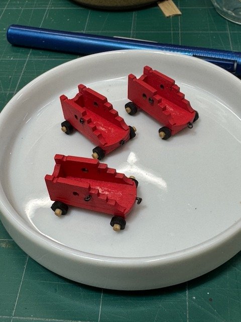
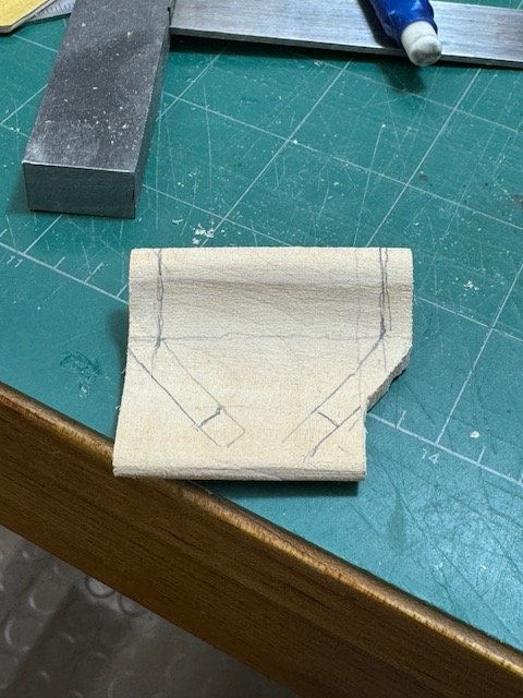
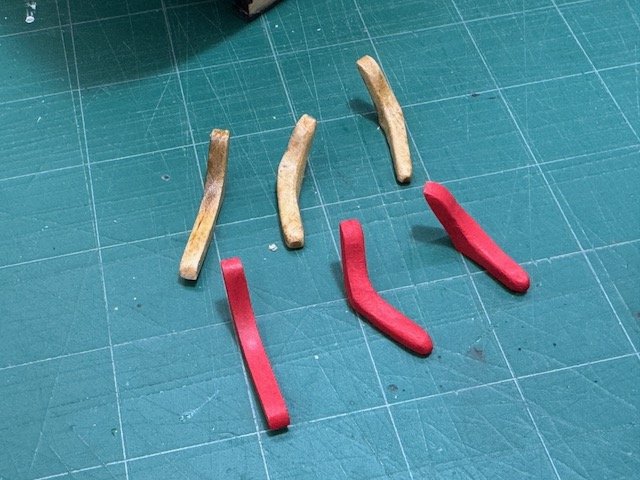
It's been a while, again, since my last posting, but I have been busy on the model with several things. First, I realized that my decision long ago to realign the gunports created conflicts with locating some of the hanging knees which brace the upper deck beams. Consequently, I had to make four dagger knees which slant away from their beam at ~45 degree angle. What I did was to make a very long blank with the same profile as one of the kit-supplied hanging knees, and then cut my daggers out of it. I needed four altogether (a left and a right on each side of the ship). These aren't installed yet, but they're all finished and ready to go. I have to make a long trip to Ring Bolt City before the knees go on. In the photo below, the kit supplied knees are on the left, and my daggers are middle and right. Just to be clear, these are needed to clear the gun ports and also to ensure there's room on the side of each port for the gun rigging. I hope to have photos of these in place "soon". Next task was assembling the guns. This step, too, is not entirely complete. Dutch gun carriages differ from the English style, and most disconcerting for me are the itty bitty wheels. For this kit they're just a bit too itty bitty to center the gun on the port, so I made an axle assembly (based on Longridge, which is the best reference I have) to get them up another millimeter. I'm also making quoins, but haven't figured out yet how to put attractive knobs on them. Another undone thing for the guns is to blacken them chemically. I am going to try very hard to do this well and not have to fall back to paint: that's the project for next weekend. Luckily, there are some very good guides on MSW. Then there was installing the ladder from the hold to the gun deck. The kit says to place the ladder at the forward starboard corner of the hatch, but I didn't like that because, since the hold over there is unplanked, there was no real footing for the ladder. So, I've put mine on the centerline, sitting on the keelson and fully under the forward edge of the beam above. This way it's got a credible footing and the post also makes sense as a beam support, which there are examples of in the Batavia plans that I have. Also, I eliminated the hand grips on the ladder below about 6' - no need for them to go all the way down to the deck. Details of the hatch were hard to come by in the kit instructions and in all the references that I have. I settled on a coaming 2mm high x 3mm wide, set the forward and after pieces on their respective beams, and the side pieces rest in the binding strakes' rabbets. I put a rabbet for a hatch cover in the frame but I don't plan to make a cover for it. Just to give an idea of how I'm going to reach Ring Bolt City, I've cut about a couple of dozen 1.5mm rings (following Chuck's technique in - I think - his Winnie log). My very rough guess is that I'm going to need 60 or so, which assumes a good deal of wastage. Finally, for some reason the kit doesn't mention gunports. But they're surely necessary. I've made them, but with the ports completely filling the space between two wales, the hinges are going to be tricky for me to make reasonably convincing. The finished model will have the ports all open. And that's all for now. I have to rush off to the job now that provides the paychecks. (Which means I'll go hunting for typos later!) Thanks for viewing, Bob
- 76 replies
-
- 11
-
-
- Pinas
- kolderstok
- (and 2 more)
-
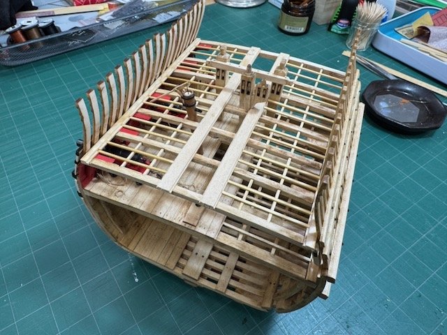
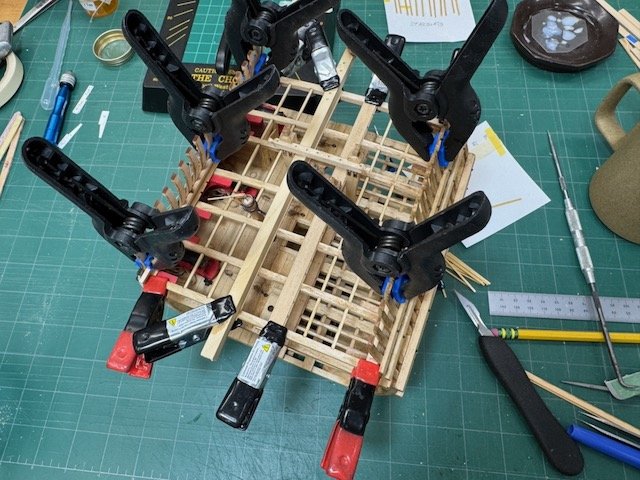
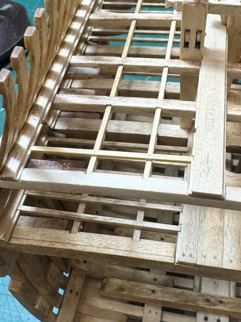
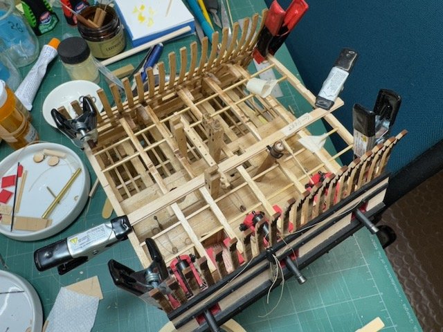
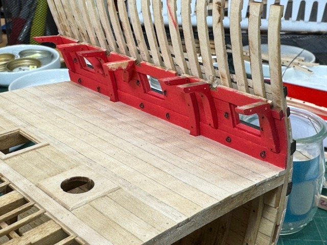
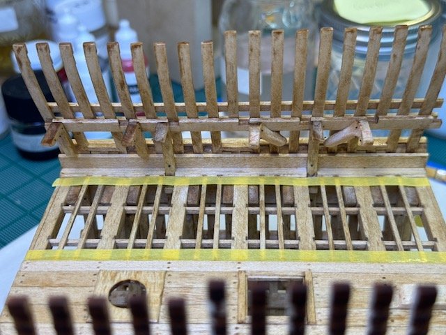
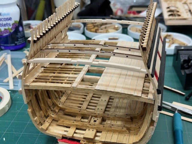
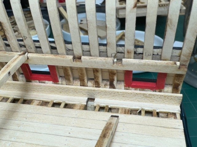
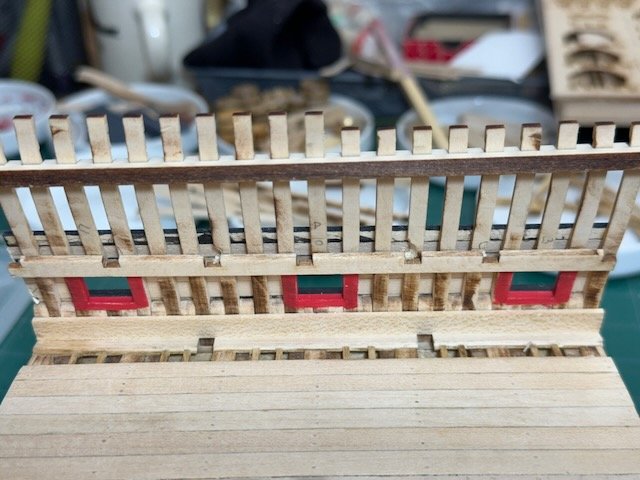
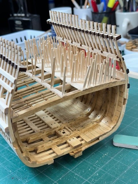
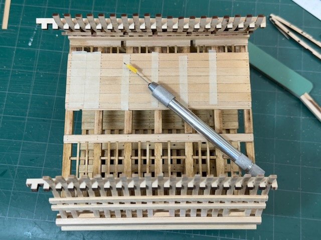
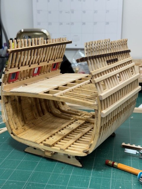
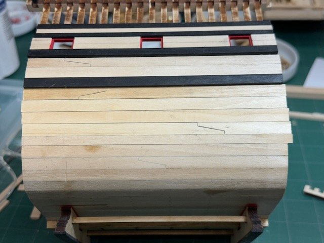
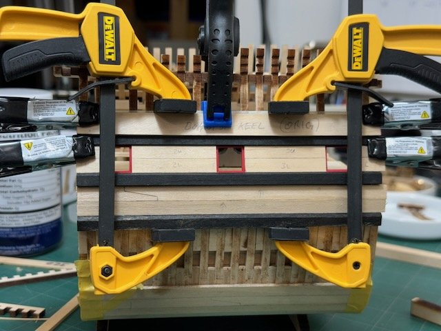
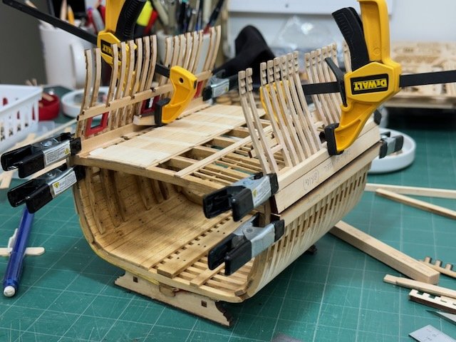
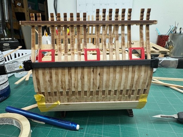
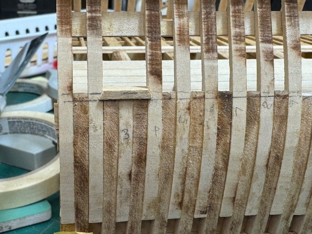
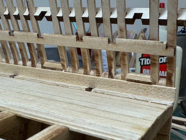
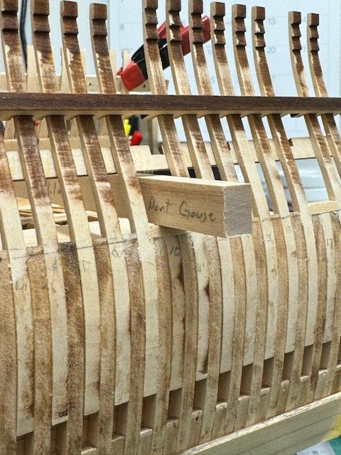
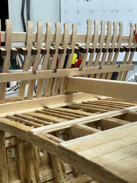
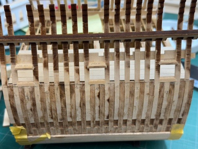
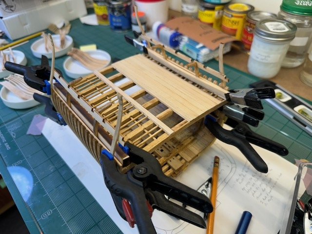
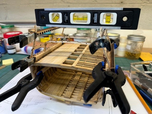
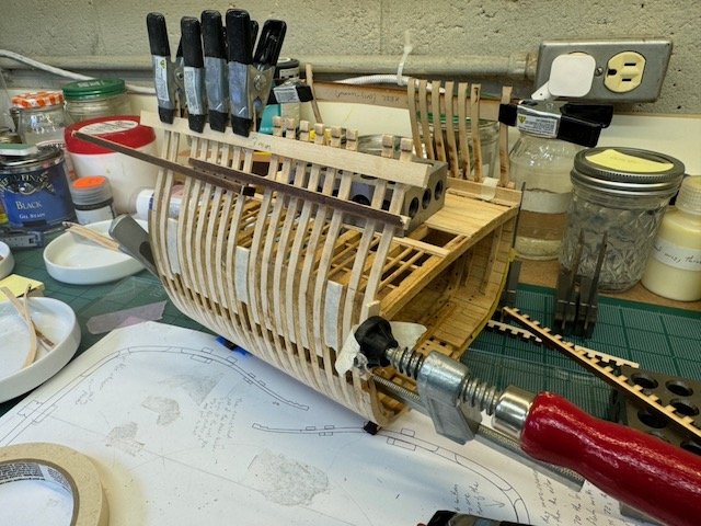
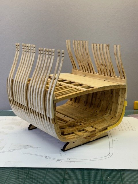
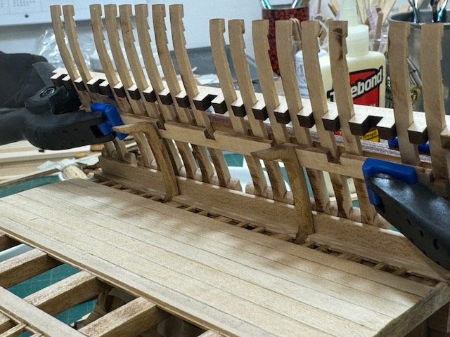
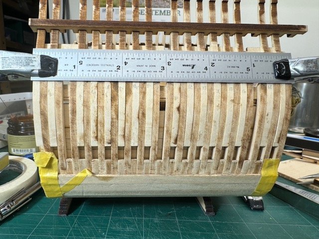
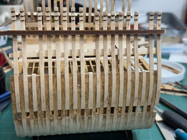
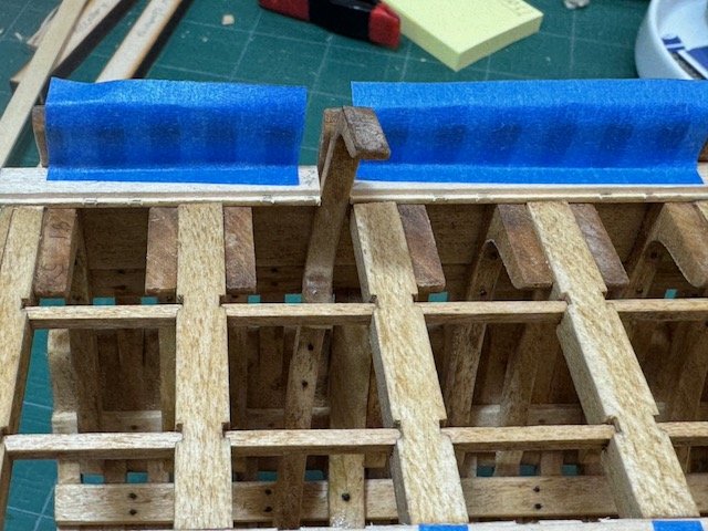
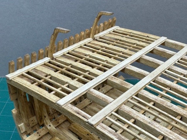
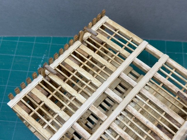
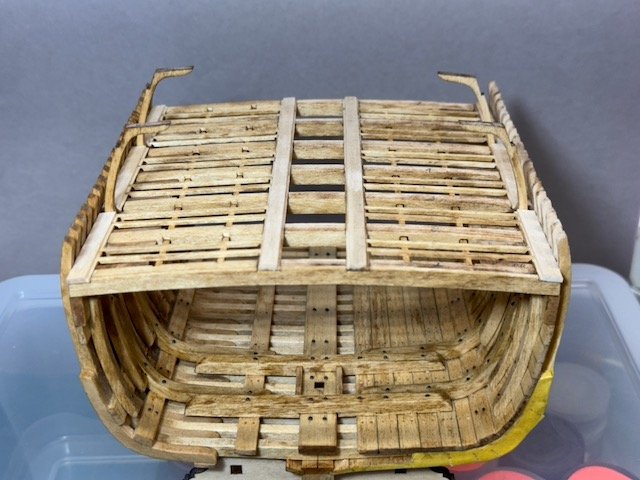
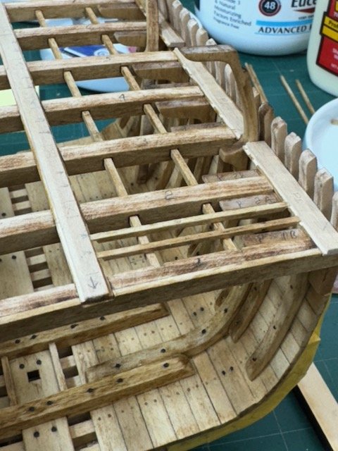
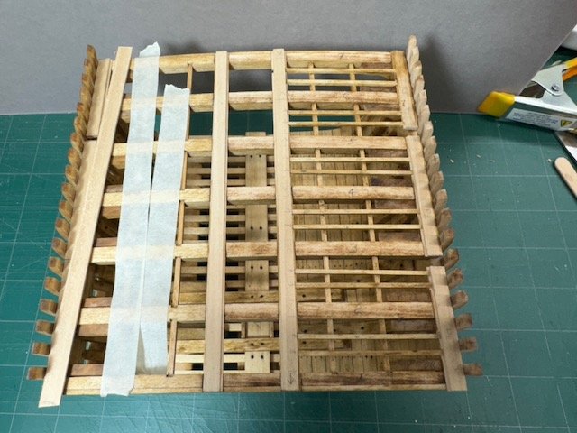
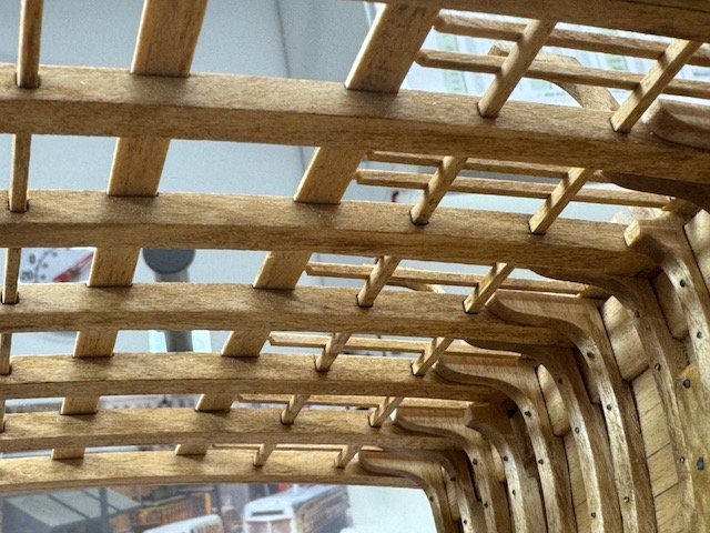
This entry is just about the upper deck beams. Although the upper deck beams will not be installed for quite a while - the gun deck will be fitted out first - I got to work preparing them early. My motivation was that I don't want my model to show the carlings as passing through the main beams. On the lower deck I dealt with this by adding blank facings on the two outer deck beams. But, for the upper deck, I'm doing something different - making two new beams which are not drilled through. This turned out to be an unexpectedly fortuitous decision! I made the new beams by cutting out slightly oversize blanks and tacking them to two of the laser-cut beams with dabs of PVA. Then I just made the profile of the blank side match the companion beam. At the end I was very careful to drill the carling holes only part ways through. Once the profiles were true and the carling holes located, I drizzled each with 91% isopropyl alcohol, waited 15 minutes, and pulled the two pieces apart. The original master beams were undamaged by this process, so I ended up with a couple of spares. With the end beams finished, I fitted each of them in place (but no glue!) (Ignore the interior beams in the next photo, for now.) That work went smoothly and I'm happy with the result. But, having done that, I thought it would be wise to make sure that the tops of these two new beams were in the same plane as the interior ones. What I was surprised to learn was that it wasn't really possible for me to put the interior beams in at all. Neither the instructions nor any of the build logs I've seen mention trouble with the upper deck beams, so I don't know why I'm special here. Because the beam shelf was glued in earlier (and had to be in order to do things like build the gun ports and install the top timbers), and because the sides of the ship are tilted steeply in at the upper deck, I couldn't maneuver the beams in from the end and twist them into place. I also couldn't push them into place from the side, through the gaps in the top timbers. The gaps are wide enough, but the presence of the higher wales on those in-tilting sides didn't leave enough clear length. Sorry, but I don't have clear photos that illustrate the dilemma. My first thought was to trim the beams so that they were just able to go through the top timbers and drop into place. I tried that on two of the beams (remember the two spares?) That did work, but trimming those arched beams resulted in them sitting 1-2 mm lower than the properly fitting end beams. That's how last weekend ended. Over the next several days I mulled over how to solve this dilemma. One solution I considered was to insert ~1mm pads on the interior beam seats: this would have let me use the two beams I'd shortened. I didn't like this because I thought that the pads would be visible and there was so little meat left for a footing on those shortened beams. Then I thought about sawing each beam in two, with a long longitudinal cut. They could be glued back together, in register I think, and the cut could be hidden under the to-be planked (starboard) side. My main objection to this is that it was a fair amount of work, fairly high risk, and the result couldn't be totally invisible. But, in fooling around with the pieces, trying to see what the possibilities were, I realized that the top timbers' thickness was enough extra space to allow one beam end to be pushed through the opposite side timbers, into the beam seat and beyond into those extra 2.5 mm and thereby allow the other end of the beam to get past the upper wale and drop into place! That's the technique I used. In the next picture of the port side, all beams are (temporarily) in place. I number them 1-7 from right to left. Obviously the end beams, 1 and 7, are fine. And you can see that the seats for both 4 and 6 align almost perfectly with gaps between the top timbers. Therefore, my job was to carve into the top timbers impeding 2, 3 and 5. Only one side of the model has to get this treatment, so I did it on the port side, which will ultimately be completely planked inside and out. And thus I have a completely hidden solution. The next photo shows how I carved 2, 3, and 5. For 3 I also had to remove part of the forward 1/2 of the beam end, but only a section that will be hidden inside the shelf's seat. Two and 5 didn't require any adjustments to the beam - just a bit of top timber chopping. Here are a couple of close-ups of the work for 2. In this case the top timber was blocking on the left. Notice that 3 hadn't been touched yet when these photos were taken. And a view checking the alignment of the full set of beams. It's not perfect now, but within sanding tolerance once they are permanently installed. You might think that it was a little scary carving those timbers, but I was relaxed about it since the worst that could happen was damage to an exterior plank which could be easily replaced. If I had forseen all of this, probably the only thing I would change is that I'd carve up the top timbers before putting on the exterior planking. Access then would be simple. It probably can't be done before the top timbers are in place because the precise alignments between beam seats and timbers isn't known until they are. Thanks for visiting, Bob
- 76 replies
-
- 6
-
-
- Pinas
- kolderstok
- (and 2 more)
-
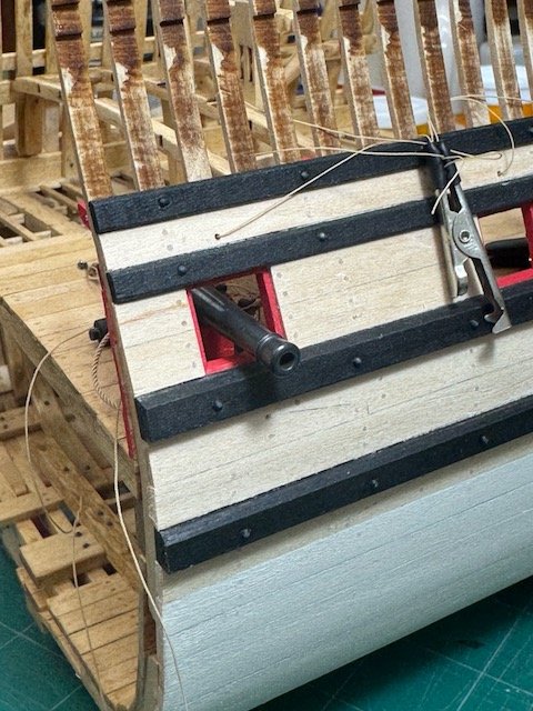
Last week I painted the port gunport frames, then installed the four wales on each side. After the wales, the regular planking to port was continued from the turn of the bilge up to the top wale. (Wales are black to port, but only stained on the unplanked starboard side.) On Sunday, I only had a bit of time available for the model, so I treenailed all of the gun deck planking that's been installed. There will be more planking later. The treenails are birch toothpicks sawn in half, as before. The holes are drilled to .9 mm, also as before. Nothing very exciting, but it's forward progress, and a couple of pages turned in the instruction book. In the same period as I did this work I also was working on the beams of the upper deck. They will be the subject of the next post (which I will start shortly, but first the pooch needs to walk.) Thanks for looking, Bob
- 76 replies
-
- 5
-
-
- Pinas
- kolderstok
- (and 2 more)
-
Olli, your Duyfken build will be fun to follow. The criticisms of the sophistication of the Kolderstok line are valid, but I also think their kits are at least as exciting as the other manufacturers mentioned, but in a different way: who else has ever given us kits of the famous Dutch 17th types? For me, Kolderstok kits are a long-held dream come true. I'm very interested in hearing how your investigations of the carving develop. Are you thinking to do it digitally, or hand carve? Bob
-
I spent the time since the last post framing the gun ports. As in other cases with this model, I worked on the mostly-hidden port side to get techniques down before finishing up on the exposed side. And after reading the instructions one more time, I decided that the proper reference point for locating the ports was the lower outer edge of the upper deck beam shelf, not the lower inner. This meant I had trimmed the futtocks .5mm too low, so to compensate I made the lower sill 2.5mm thick rather than 2. After the lower sills, I did the uppers. The kit comes with a template piece to establish the height for the port opening, but for easier marking at the proper angle, I made a longer one that could reach all the way across. Making the sills was slow work, but not very difficult. As always, my greatest trouble was marking precisely and then actually seeing the marks so I could cut to them. At the end, I made a rough check of how the cannon would sit. Since I am expecting that I will make my own wheels for the carriages, this trial doesn't matter much. (I've learned from build logs that at least one other modeler of this kit has made his wheels to position the guns properly.) In the final picture you can see that the lower sill of the center port doesn't appear to be horizontal. That's something I hadn't noticed in real life, and I'm going to need to do something about it. That's all for now. Thanks for looking, Bob

- 76 replies
-
- 7
-
-
- Pinas
- kolderstok
- (and 2 more)
-
It is a great looking model! A friend of mine made a CLC single (1:1 scale) many years ago, and your model brings back fond memories.
- 33 replies
-
- 1
-
-
- midwest products
- kayak
- (and 1 more)
-
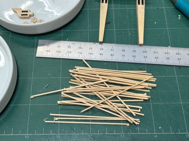
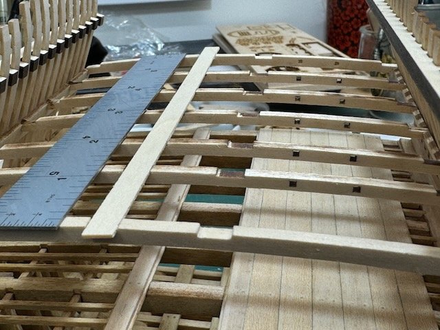
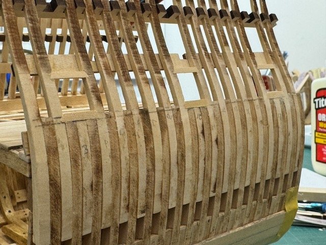
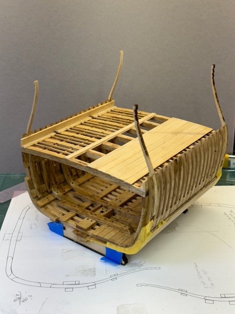
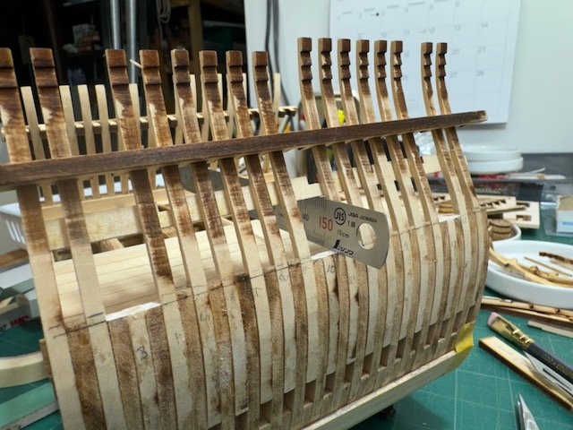
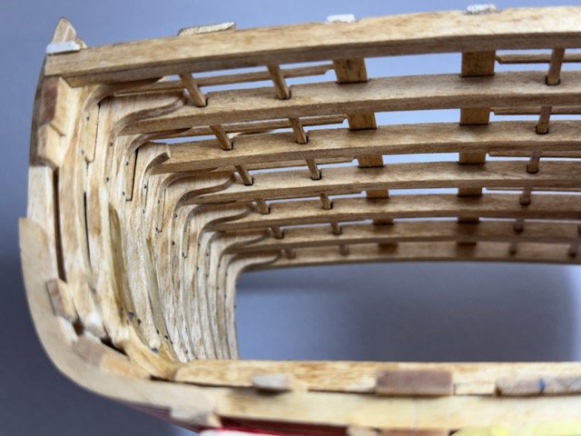
The next order of business after finishing the ledges was to plank the port side of the gun deck. Instructions say to leave the three outermost planks loose until the trusses (futtock riders) are installed. But just a single plank opening is sufficient for me to move them in and out, and that's also what the instruction photos show. I made sure to stain the undersides of the planks before installing them! The nibbing strakes are also installed now; these are the lowest planks, P&S, on the interior sides. For me, these are important items. First of all, their thickness controls how well the futtock riders will sit against the sides of the ship above and below the gun deck. Secondly, their upper edges are useful when checking levels, so it's good if the two pieces have the same, uniform width. The instructions call for the strake to be 2mm, but on my model that was too much. After sampling a few thicknesses for fit, I found that 1.5mm was perfect for my futtock riders. The "top timbers" make the last level of hull framing. Construction of them is not very different from the lower levels of futtocks, but this time there are two different sizes. The first 9 top timbers have two notches at the top for clinker planks, while the last 10 are a little taller, with three notches. The lower two notches are at the same level for the entire length, which is an important detail to observe when installing them. Before installing any of the top timbers figure out where you want your gun ports to lie, because the timbers over the ports are not installed yet. The instructions are conflicted on this, but in reading the other build logs I think the designer has agreed that putting the ports at timbers 3, 10, and 17 looks best. That's what I'm doing. As on the lower framing levels, the corners are installed first. I followed my earlier practice: all four of mine lie between two futtocks. So my two initial forward timbers are actually one frame in from the absolute corner - which I installed last of all. (Remember, the two-notch top timbers start at the end where the mast step is.) I was very, very careful to make sure these were properly located, that the tops of the two pairs were level, and that the notches were horizontal. I did find that the laser cut timbers match the kit's drawing of the framing very precisely, so in a sense this was quite easy - all the checking I did only confirmed that everything was where it ought to be. The instructions seem to say that the upper deck beam shelves should be installed after the four top timber corners are installed, but I waited until all the timbers were in before doing mine. The alignment combs are just as useful for installing this level as in the earlier ones. I'm posting a lot of photos of this work since I often wished I had more examples to look at. When all the timbers were installed (aside from the gun ports), I realized one timber was not quite properly seated. As I had used PVA to glue them in, it just took some 91% alcohol and a bit of patience to pull the misaligned frame out and reinstall. The shelves went in nicely, and confirmed that my 1.5mm nibbing strakes were the right thickness. The alignment of the shelves, like all the other framing work, is critical. I measured and checked every way I could before actually applying glue. The futtock riders, by the way, are not glued in yet - they're held in place during this work by tape down in the hold. Once the shelves were installed, I started working on the gun ports. The lower edge of the frames on which the port sill will lie is found by using a laser cut block that's 15mm high. The top of that block is put against the bottom of the deck shelf and the bottom of the block marks where to cut the frames. At least that's how I interpret the instructions, and it seems to result in a good location. I also believe that the instructions want the lower sill to be horizontal, i.e. parallel to the plane of the waterline. The supplied block was not much help for finding the horizontal, but I used a 150mm ruler for this which, by good luck, was 15mm wide. With the ruler I could easily get a horizontal line by putting the top of the ruler against the bottoms of the two shelf beams. Until it dawned on me that my ruler was perfectly sized, I was expecting to have to make a long piece of the right width. (The ruler I'm speaking of is not the one on the next photo, but it shows up in the last set of photos, below.) That's all for now. Have to make some coffee and descend to the basement for today's work. Thanks for looking, Bob
- 76 replies
-
- 7
-
-
- Pinas
- kolderstok
- (and 2 more)
-
Installing ledges on the starboard (exposed) side went very smoothly today. After all the practice I had on the soon-to-be-covered port side, marking and cutting the mortises was a quick job and there was much greater consistency in the result. Marking is tough for me with these tiny pieces, but I recently acquired a pair of Narex violin marking knives (with right and left hand bevels). Besides being sharp, the angle is quite sharp, letting me get into tight areas. They helped a lot marking the mortises. I also tuned up my little 1.5mm flat chisel so that its edge was straight as well as sharp. The chisels are from Micromark, and I can't say I think they're wonderful tools, but they are affordable and useful. You can see in the finished result that the top/left side of the next photos is more uniform than the other. And, after today's work, the look of all the deck support timbers is similar to the illustration from Witsen back in post #31.Today's work is on the left. Tomorrow I'll be working on planking the port side and getting the frames up for the upper deck. Thanks for looking, Bob
- 76 replies
-
- 9
-
-
- Pinas
- kolderstok
- (and 2 more)
-
This is a short post. I've started installing the ledges for the gun deck. Ledges are the small strips parallel to the deck beams which rest on the carlings. I'm trying to make their joints with the nibbing and binding strakes more like authentic practice, which is a lap joint into the rabbet on the strakes. This is a finicky process for me, since those pieces have a tiny 1.5 mm cross section. Yesterday I finished the port side, and that's what these photos show. I did port first (which will be almost entirely hidden once the planks go down) so I could settle on the procedures for the other side, which will remain unplanked. Later today I'll start the starboard side. Starting in August I've cut back my work week to just three days, so in theory I should start progressing a little less slowly. (It takes some time to adjust to having a standard 4-day weekend.) Thanks for looking, Bob
- 76 replies
-
- 3
-
-
- Pinas
- kolderstok
- (and 2 more)
-
Thanks Canute & Chuck for your comments. I tried to do approximately as Canute advised: I put on a first coat of Minwax polycrylic as a sealer, but I don't think that I sealed well enough. The intent was for the stain to act as a glaze, i.e. coloring the wood but not soaking into it. Next time I'll be more thorough with the sealer. I do want the aged look that stain can provide, I just don't want it to look like the ship's cat threw up on it. Chuck, what wood dye are you using? Bob
- 76 replies
-
- 1
-
-
- Pinas
- kolderstok
- (and 2 more)