stelios
-
Posts
53 -
Joined
-
Last visited
Content Type
Profiles
Forums
Gallery
Events
Everything posted by stelios
-

Symiaki Skafi by stelios
stelios replied to stelios's topic in - Build logs for subjects built 1851 - 1900
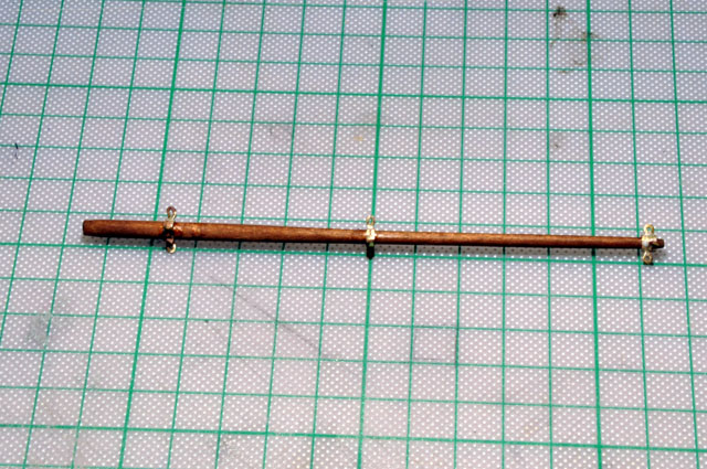
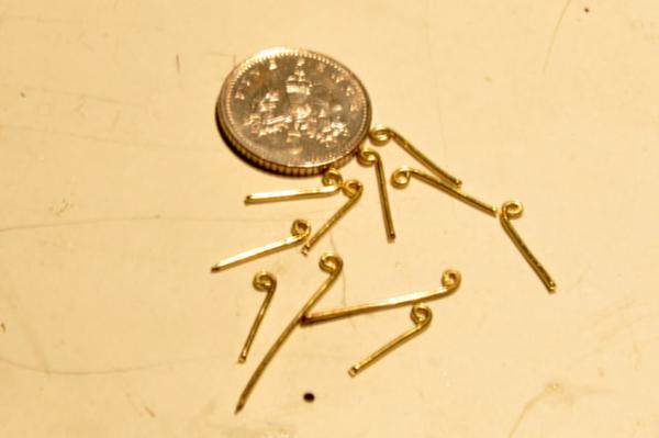
In the following sequence of pictures I tried to illustrate the bowsprit ironworks. (or to be accurate brass works!) I did not have brass tube at the time to cut the collars, so I had to make them by myself.Not difficult really, I just coiled brass wire at the desired diameter, then soldered in order to become a solid ring. A little trimming with the needle files, and they are ready.! Next drill four holes insert the rings, and solder them. Once ready, fit on the bowsprit, blacken them. Finally varnish the bowsprit. Not bad I guess...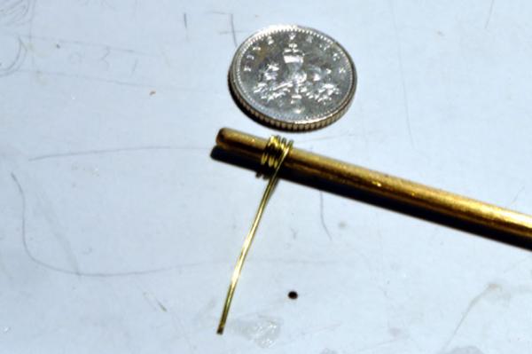


-
Symiaki Skafi by stelios
stelios replied to stelios's topic in - Build logs for subjects built 1851 - 1900
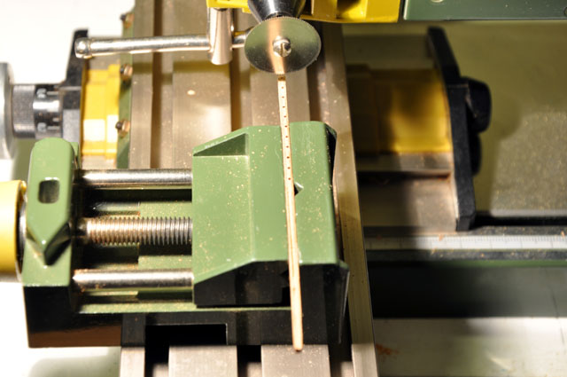
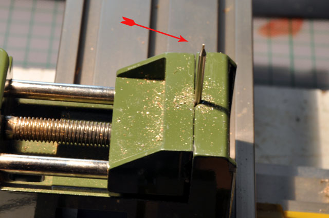
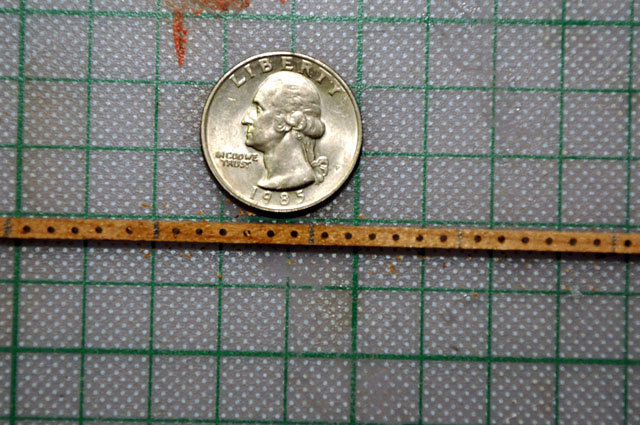
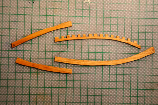
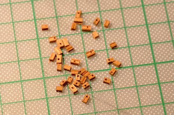
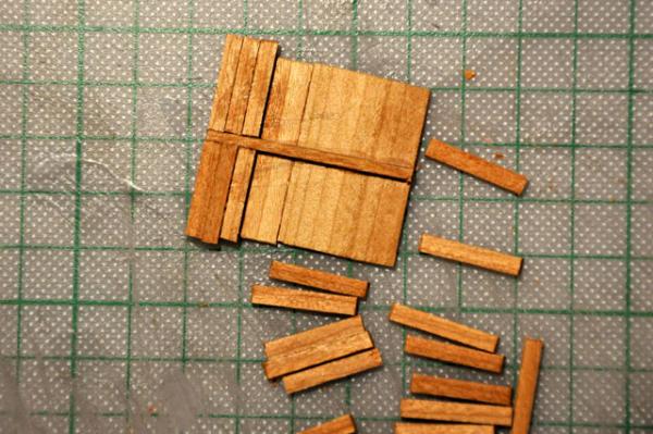
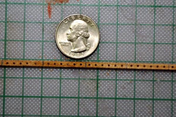
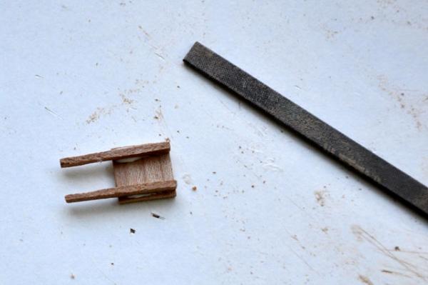
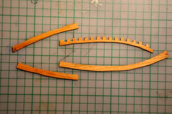
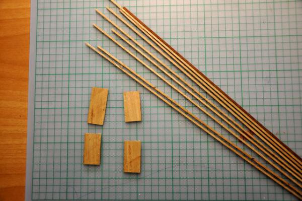
Having finished the hull construction together with the all major superstructure features, it was time to start phase number two, and that was the construction of the masts, the sails and all relevant elements. The details involved are many, even if you decide to build a "simple version"! To start with, I started making some blocks. Admittedly, they cannot be compared with the blocks made by some fine modellers in this forum, but the whole process was fun, and at the end of the day, this is all about it. The process is relatively easy: Drill holes on a strip of wood at constant intervals, then cut the strip into pieces. For example, if the gap of the holes is say 3mm, I cut the pieces with the same gap, allowing the hole to be at the beginning of each piece. The grooves shown on the blocks was made before drilling the strip. It does not really add to the functionality, but at a later stage it will help the string to look better when it will pass through the hole of the block. Needless to say that a drill stand and a compound table are necessary to do such a job. Another element of this process are the various multipurpose rings as I call them, because they will be used in various situations, as is, or as part of a more complex construction. In the picture below, you can see how a broken drill bit is used to shape the rings: I just coil around the tip (with the pliers) the brass wire. the rings are ready to be soldered...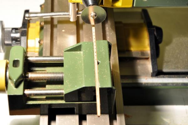

-
Symiaki Skafi by stelios
stelios replied to stelios's topic in - Build logs for subjects built 1851 - 1900
Ian and Dave, thank you! Stelios -
Sherry, It is a fine build and a well documented log. regards Stelios
-
Symiaki Skafi by stelios
stelios replied to stelios's topic in - Build logs for subjects built 1851 - 1900
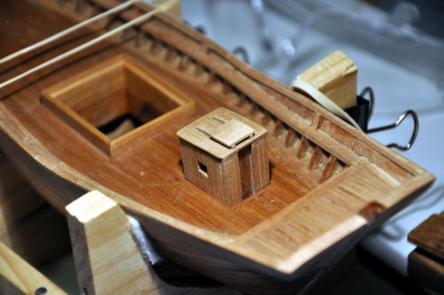
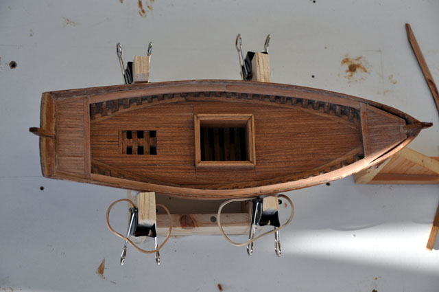
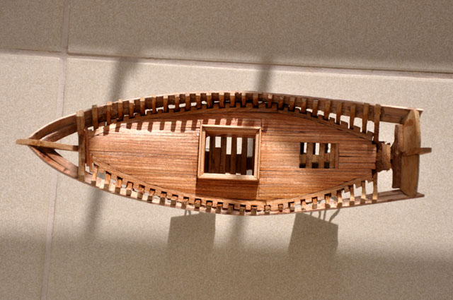
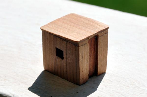
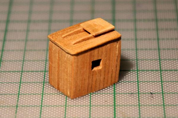
In the meantime, various wood-works were taking place such as the construction of the hatch cover and the pin rails. In the last photo, (dated 28/11/2011) the ship is varnished and all wood works completed. Next step is the mast construction, the sails and the rigging.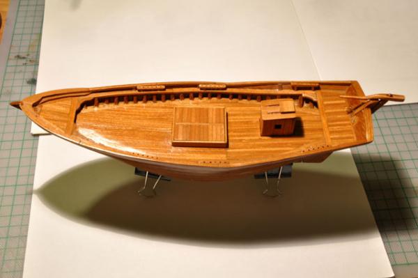
-
Symiaki Skafi by stelios
stelios replied to stelios's topic in - Build logs for subjects built 1851 - 1900
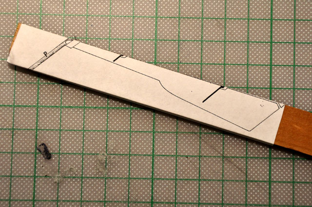
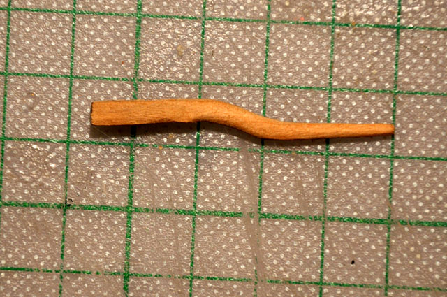
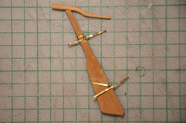
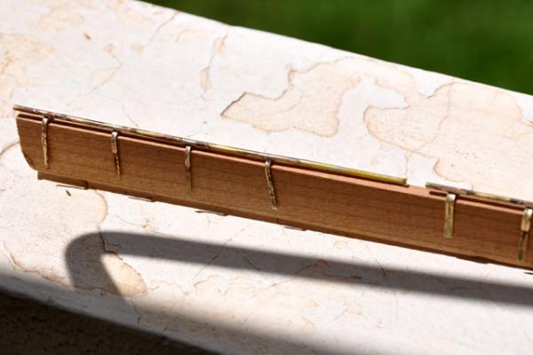
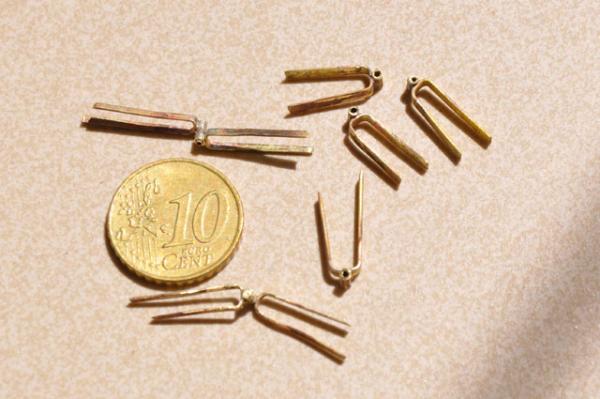
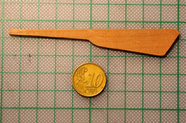
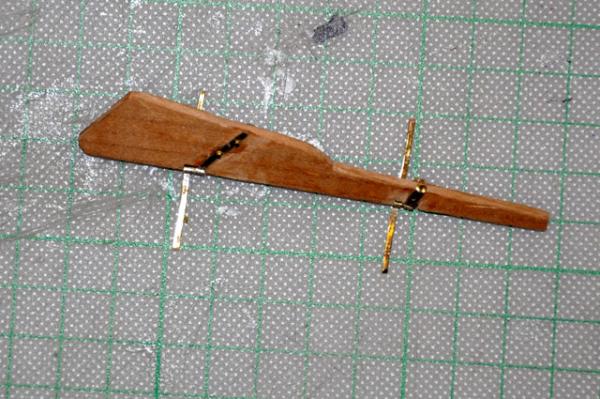
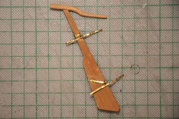
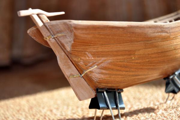
The rudder: In the following pictures you can see the various stages of its construction. It is worth noting that the hull was varnished with one coat, just to avoid the smudges o on the wood. The final coating was applied after all wood works were completed. For the record, the date the rudder was fixed on the hull was November 27th, 2011, whilst construction of the brass hinges were logged earlier, on Aug 14th 2011.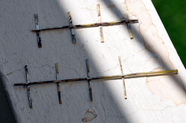


-
Symiaki Skafi by stelios
stelios replied to stelios's topic in - Build logs for subjects built 1851 - 1900
From the captain's log: September 23rd, 2011: Various works on the bulwarks and the construction of the deck house; it is shown on the deck (dry fit last picture), whilst in the previous ones you can see the various construction stages. An entire summer had passed with minimum to no modelling activity. This is at least what was recorded in my photo log...

-
Symiaki Skafi by stelios
stelios replied to stelios's topic in - Build logs for subjects built 1851 - 1900
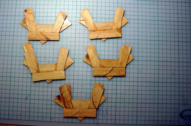
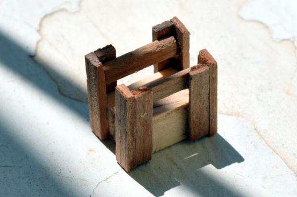
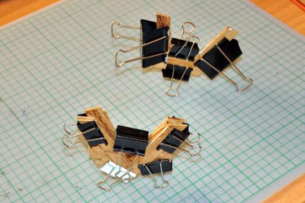
Following the same methodology followed to build the abacus, I built the forecastles. For the record, the picture showing them installed was taken on 27/03/2011...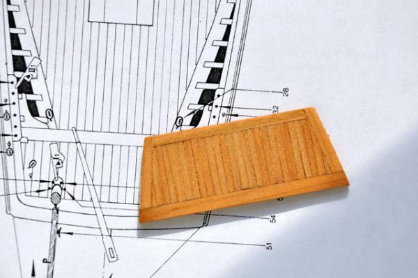
-
Symiaki Skafi by stelios
stelios replied to stelios's topic in - Build logs for subjects built 1851 - 1900
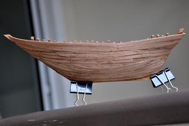
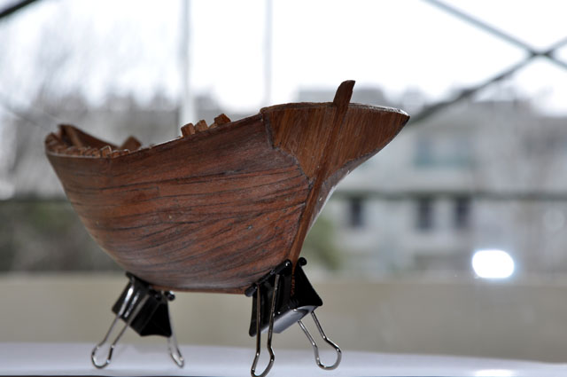
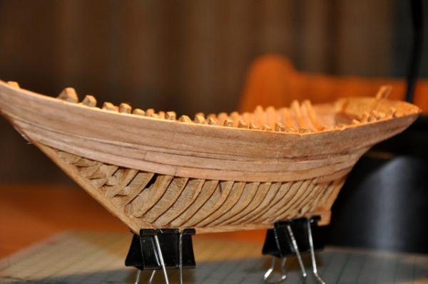
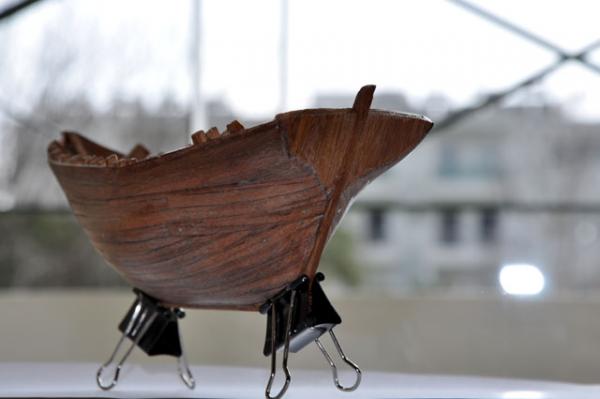
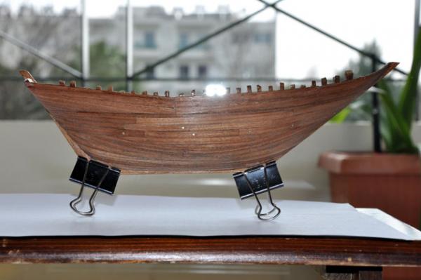
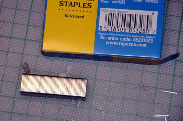
Hull Planking Skafi's unique hull shape made planking challenging. It took a lot of plank bending ironing trimming in order to achieve a respectable outcome. Initially I made the mistake to use brass nails with visible head. I used only a few, so the problem is not very visible, only to those who know... For the rest I made my own nails, (without head) made out of galvanized steel. My source was a pack of staples, purchased from the local office supplies store. The gaps were filled with small flakes of wood reinforced with carpenter's glue. Finally, it was sanded down, and varnished. Its unique shape made planking a challenging process It took a lot of sanding to smooth down this ugly duckling The home made nails are not visible at the final stage This is the first varnish coat, to avoid smudges... Galvanized staples. they can be used as nails. Stelios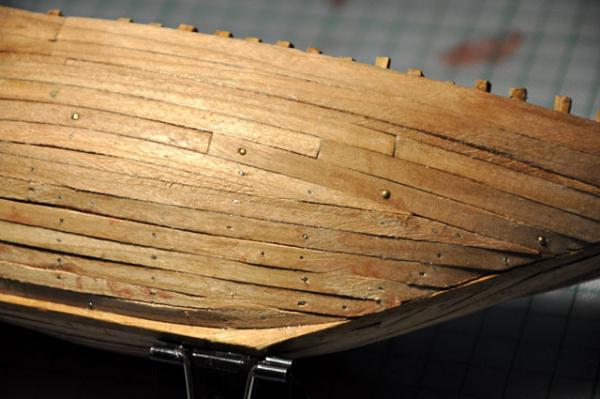

-
No I did not use any flux prior to soldering, however, as mentioned in step three, the trimming with the needle files cleans the parts. Stelios
-
I use a simple and cheap torch bought from the internet. I was inspired by Russ' tutorial posted at the time.
-
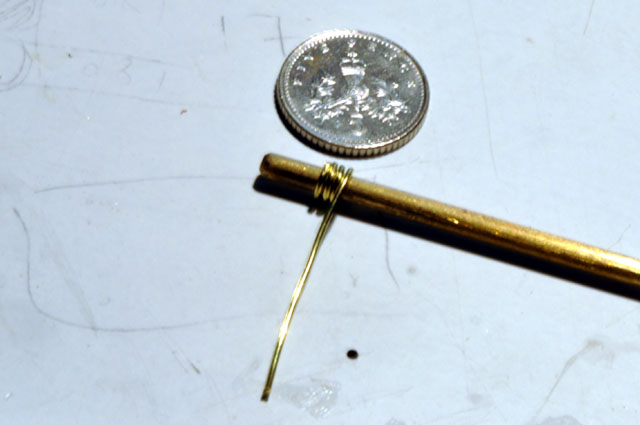
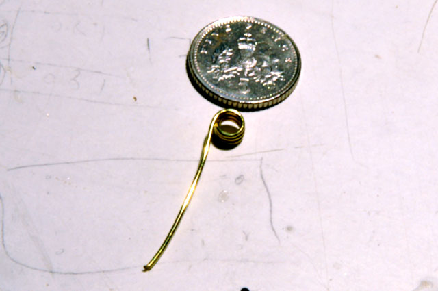
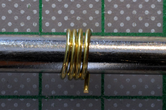
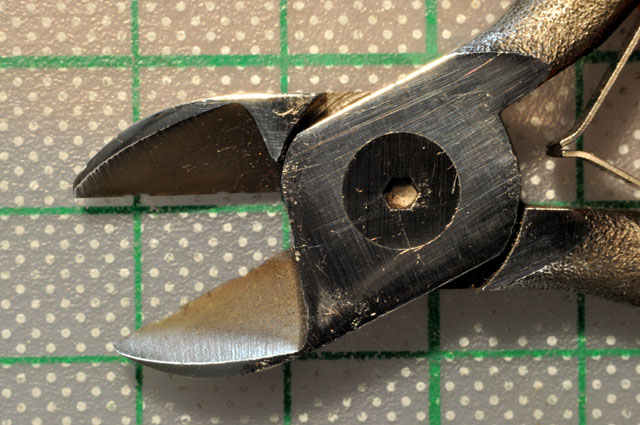
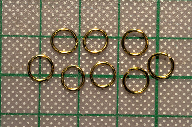
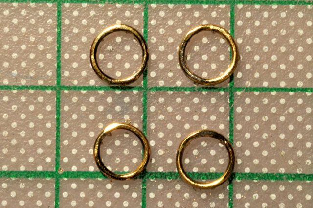
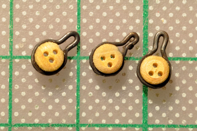
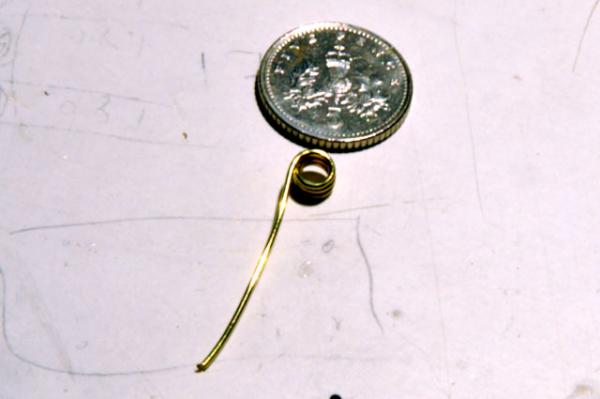
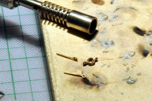
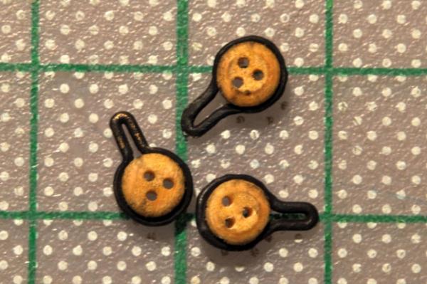
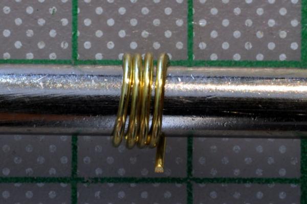
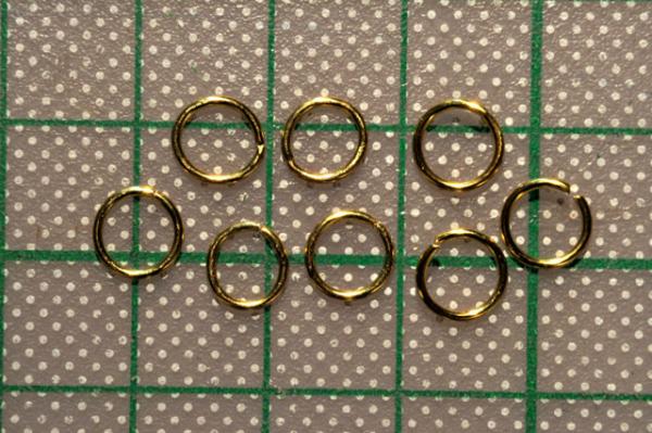
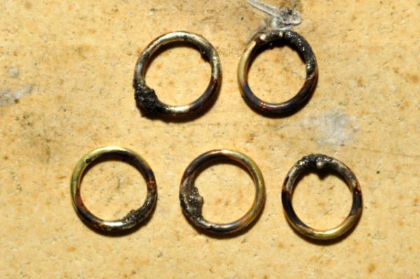
Dear all, Silver soldering has become one of my favorite activities in ship modeling and as it happens this period to be in the mast and rigging installation phase, I took pictures to log the process. In this section I see there are various ineresting and informative topics, yet I took the liberty to contribute my own version, always seeking your critique. Step one: coil the brass wire around a brass rod to form a spyral. In my case I used a screwdriver as its diameter was the ideal for the specific deadeyes. The selection was done by trial and error. Step two: remove spyral from the rod and cut all way with cutting pliers. By doing so, we create small rings. The picture below was not really necessary, but anyway, here it is... Step three: with needle file trim the joining surfaces of the rings and bring them into contact. In the picture below the three rings on the right we left on purpose unfiled and not shaped, in order to highlight the difference with the counterparts on the left. Step four: silver solder them. in the picture below this is how they look immediately after, without any further treatament. Step five: with the aid of needle files and a rotary brush, they change completely look. Step six: With the aid of a circlip pliers squeeze the ring in order to take an oval shape wide enough to accomodate (at a later stage) the deadeye. Next, still holding the oval shaped ring with the circlip pliers, squeeze it further to take the desired shape below. Insert the deadeye, align the holes and sueeze it to its final shape. (I know, more pictures would be appreciated, but at this stage you need a partner, not available unfortunately). The final step is to blacken the brass. I use a product containing selenious acid. It is used to blacken engravings on brass. Stelios

-
Symiaki Skafi by stelios
stelios replied to stelios's topic in - Build logs for subjects built 1851 - 1900
Deck Planking In the following sequence, you can see the methodology followed to plank the deck. Thin square strips of wood (about 1mm x 1mm), were glued together one next to other on the beams. Once finished, the surface was smoothed down and varished (one coat) to avoid smudges on the surface. For the record, these pictures were taken between 20 and 24/12/2010 Stelios
-
Dead Eyes (avant premiere) - moved by moderator
stelios replied to stelios's topic in Masting, rigging and sails
Thank you guys, much appreciated! Indeed, they're (silver) soldered. Great mentor was Russ, with his tutorial posted into this site (before the destruction...) Stelios -
Dead Eyes (avant premiere) - moved by moderator
stelios posted a topic in Masting, rigging and sails
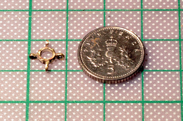
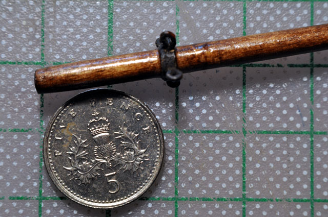
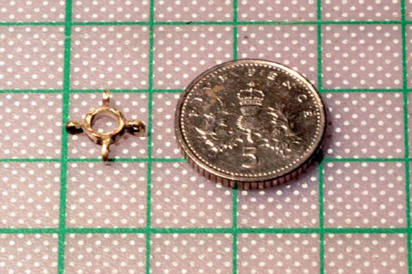
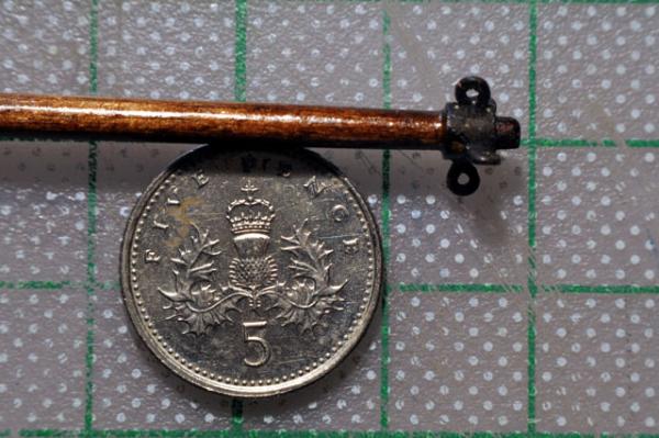
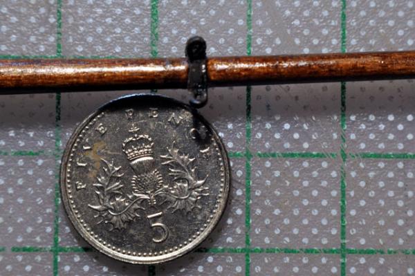
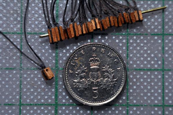
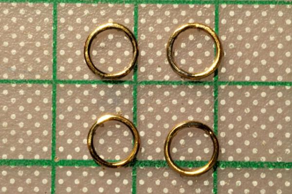
Dear all, Until my build log is updated with the lost posts, I take the liberty to post here the first three dead eyes that will be used on the shrouds. I have two reasons to brag about, firstly the iron work is respectable (consideling the size, and second I achieved a good macro picture (my other long forgotten hobby)! In order to get an idea, each square on the mat is 1cm by 1 cm. Stelios
-
Symiaki Skafi by stelios
stelios replied to stelios's topic in - Build logs for subjects built 1851 - 1900
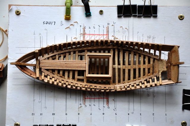
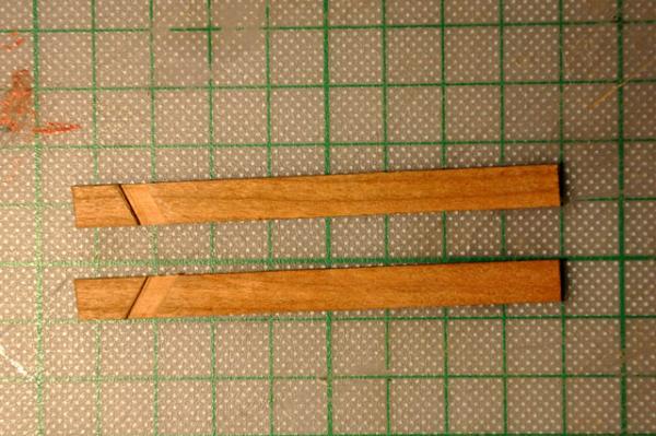
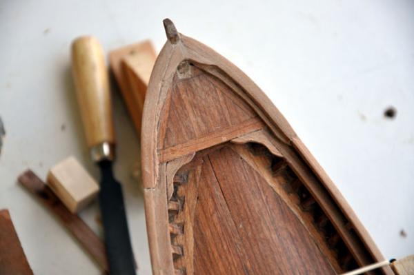
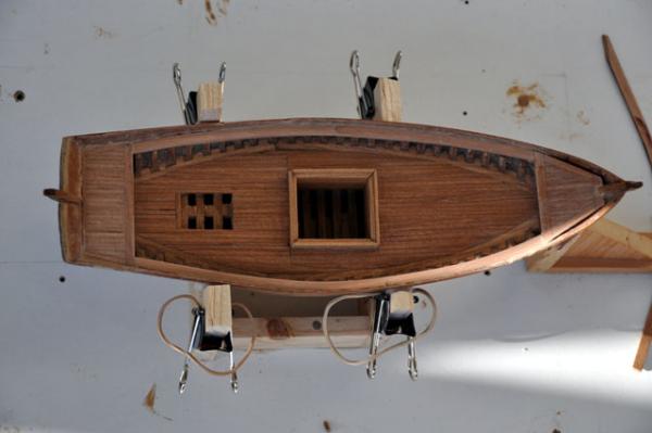
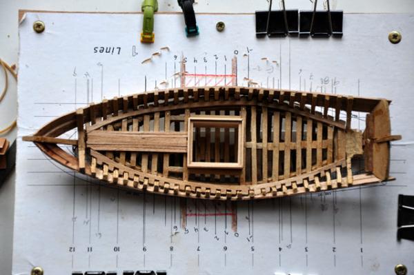
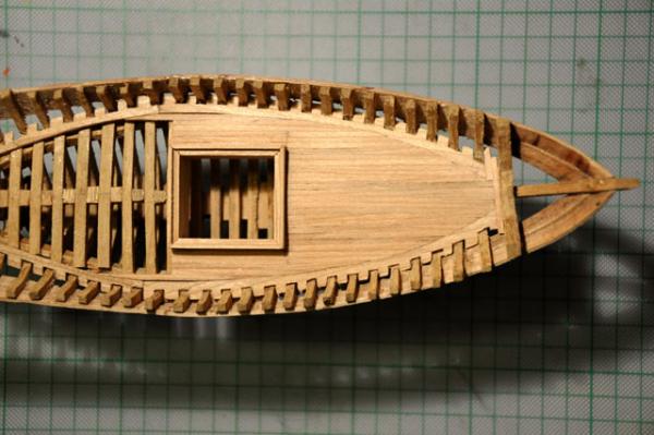
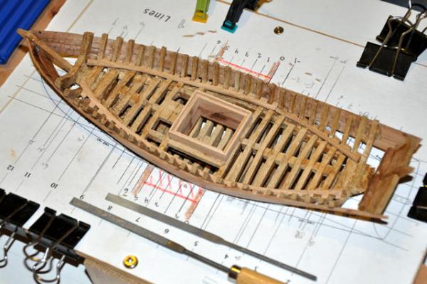
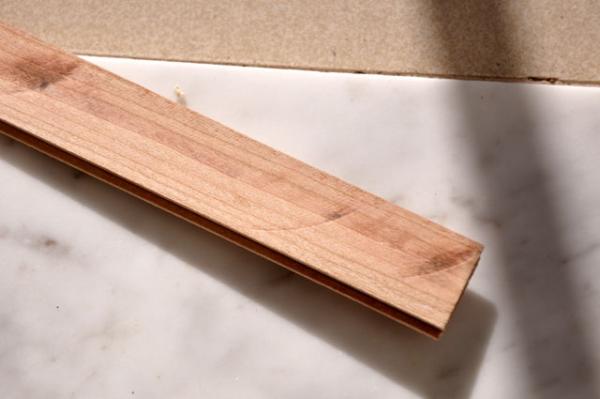
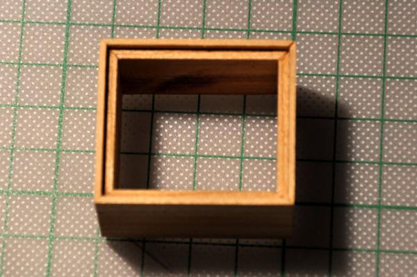
FORECASTLES, DECK BEAMS, HATCH As part of the deal with a carpenter who was employed to do some wood works in the house, it came to my possession five pieces of cherry wood, which I intend to use for the planking of all exterior of my current build. From that point and onwards, the build continues with cherry wood, starting with the forecastles of the ship. Needless to say, cutting down to strips it was a neat job, much easier compared to iroko: The forecastles were build with the same method used for the abacus, (please refer to my previous post). The ned results was very good; iroko is a strong wood, a good choice to build the keel and the frames, whilst the cherry wood is ideal fro the visible parts of the hull. The build is continues with the construction of the deck beams; the picture below shows the first steps of the deck construction: I have dry fitted the first beams that will host the hatch. Stanchions The stanchions installation is inter-related with the correct thickness (scale) of the upper part of the frames. Hence, before continuing with the deck beams and in order to be able to trim effectively the upper part of the keel frames, I decided to do some outer planking first to secure the bulwark shape and then trim the frames. Otherwise, trimming (or weakening) them, might make difficult (at a later stage) the bulwark construction. After the first planks were in place, it is safe to continue with the installation of the rest of the deck beams. Please notice that they sit on some sort of guardrails, (glued strips of wood on the inner part of the frames.) The Stanchions under construction The hatch installation This is one of my favorites: two strips of wood glued together and then cut at 45 degrees and form the square shape of the hatch. I let the picture s tell the story: Now, the deck is ready for planing. to be continued...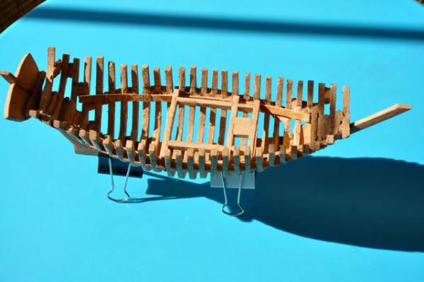


-
Symiaki Skafi by stelios
stelios replied to stelios's topic in - Build logs for subjects built 1851 - 1900
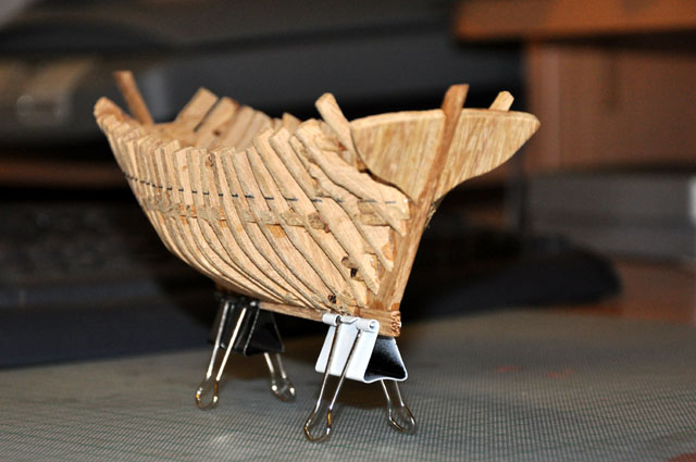
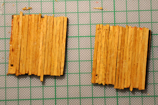
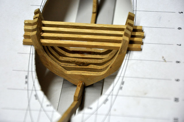
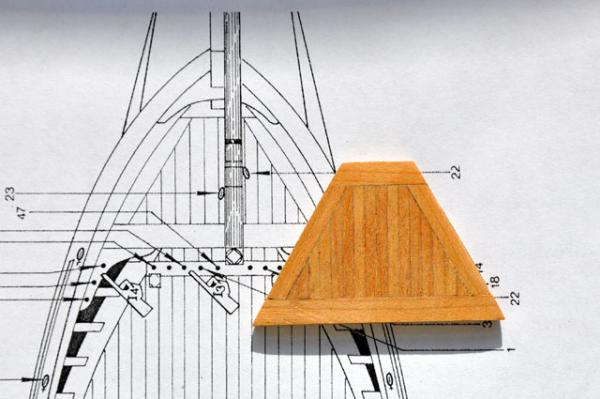
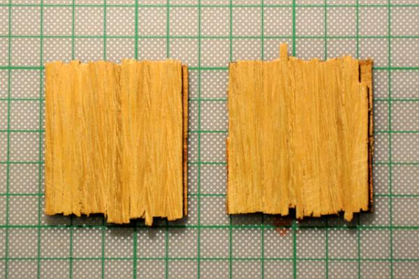
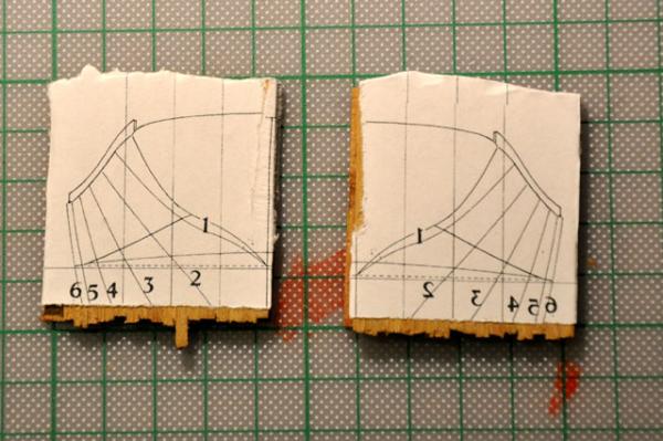
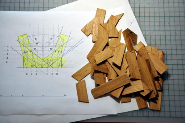
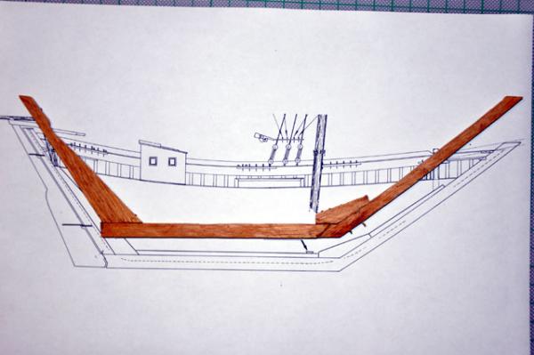
The abacus (stern) After the installation of the frames and prior to the installation of the deck beams, it was the turn of the abacus construction. The abacus (this is a Greek word by the way) are the wooden panes that make the stern. In the pictures below is shown the steps of making the two panels: Wooden strips, aprox. 1mm thick were used; they're glued together on those small flat pieces of wood to imitate the planks. In the picture below one can see how it looks like, before sanding them down: Same after sanding them down In order to cut into shape, the paper pattern was glued on; the method is simple: print the pattern from a laser printer and glue it. I used quick mount glue (spray) which can be found in all stationery stores. In the next two pictures, one can see the final outcome after the frame installation and the stern abacus. The spacers are also seen that now serve as joints between the frames (see my previous post). Stelios

-
Symiaki Skafi by stelios
stelios replied to stelios's topic in - Build logs for subjects built 1851 - 1900
FRAME CONSTRUCTION This is a brief summary of the frame construction. In principle, the steps followed to build the frames are: Design the frames Design the blanks Prepare blanks Make frames Fit frames on the keel. The picture below relates to step 3). Please note that the coffee mug is part of the equipment needed for a successful frame construction. Office stationery can be very handy as seen in the picture below… I took into consideration your feedback (NB: from the original posts) and I marked in advance on the template the position of the frames; I must admit, it made my life much easier. Secondly, the spacers are not movable any more, I glued them between the frames. I positioned them underneath the wooden template. Once the frames are in place, the spacers will be cut and trimmed leaving only a small joint between the frames. These joints as a whole, will provide extra sturdiness to the entire construction. Stelios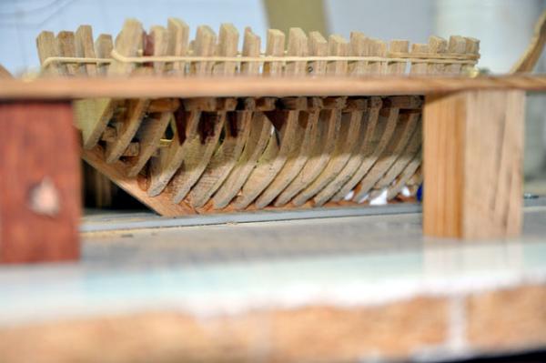

-
Symiaki Skafi by stelios
stelios replied to stelios's topic in - Build logs for subjects built 1851 - 1900
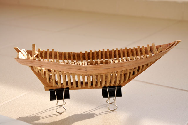
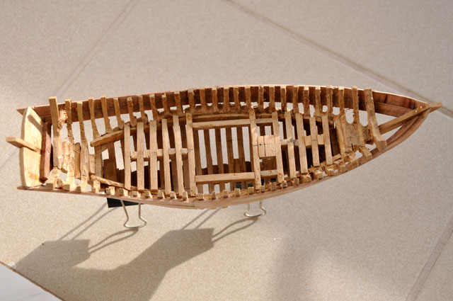
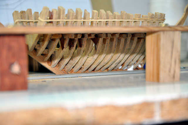
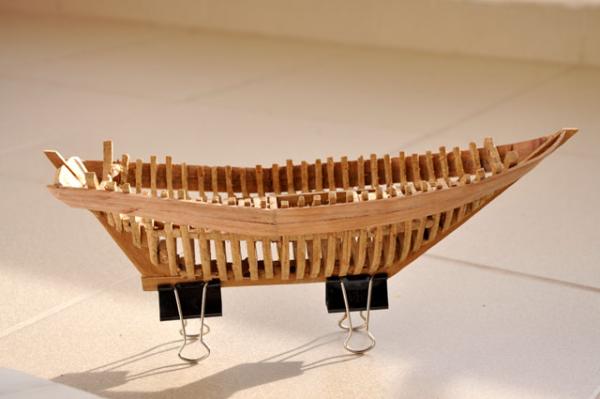
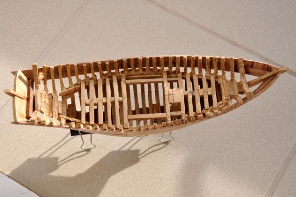
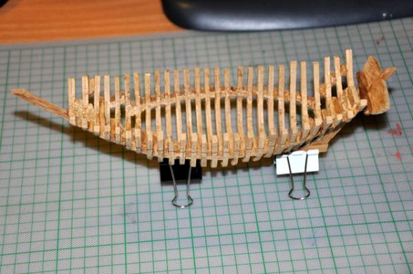
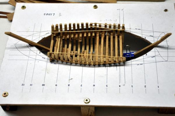
FRAMES In the below pictures you may see the first 5 frames were fit on the keel. The end result is satisfying, for various reasons: The wood in use (iroko) did not create any troubles; the scroll saw gave clean cuts and the sanding produced clean surfaces with the correct thickness (4 mm). The most important is that the frames were fit in the expected position, with no visual deviation from the drawing board. The horizontal sticks serve as spacers and are removable. Stelios
-
Symiaki Skafi by stelios
stelios replied to stelios's topic in - Build logs for subjects built 1851 - 1900
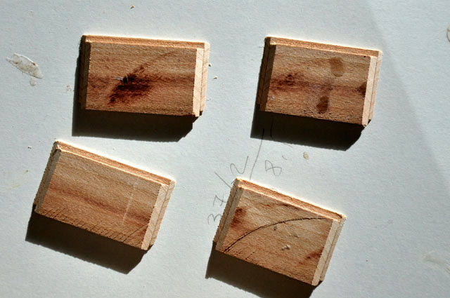
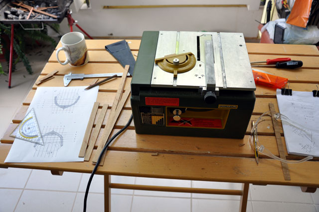
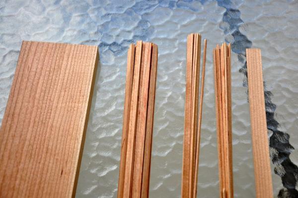
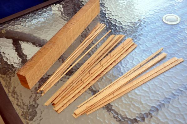
FRAME BLANKS The frame blanks are used to construct the frames. The principle is very simple: glue on the frame blank the shape of a frame, cut it then with a fret saw, and you're ready. The frame blaks themselves are made out of wooden strips; It took me some time, as I had to cut strips of wood from a bigger log. The picture below shows a log similar to the one I cut such strips. Starting from the mid-ship frames, the next step was to design the blanks with the appropriate shape and size cut the wood strips according to their pattern. The protractor is very handy in this case, as the angles of the parts must be accurate, otherwise they will not fit together properly. The picture below shows the first 5 blanks. They are marginally thicker than the required, but with a little sanding this will be corrected. Next step is to design the frame templates and stick them on the blanks.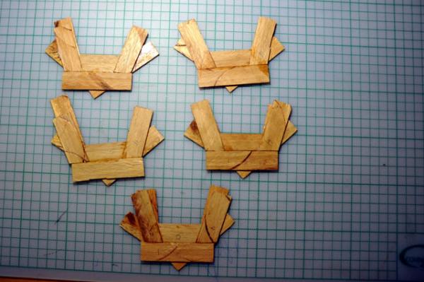
-
Symiaki Skafi by stelios
stelios replied to stelios's topic in - Build logs for subjects built 1851 - 1900
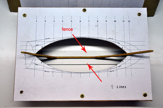
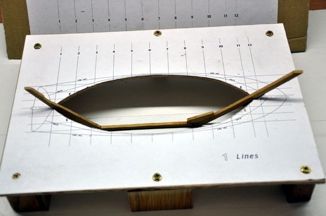
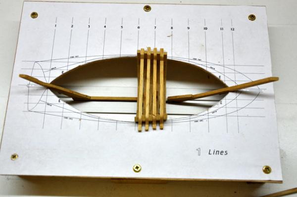
The fence mentioned in my previous post has been fit on the board. Before securing the upper board in place, I first needed to build the keel with the stem and stern posts, as seen in the next picture: In the next two pictures the upper board as fixed in place and ready to accomodate the frames. A few words about the wood I used for the keel and the frames: it is iroko hard wood with good texture and I found no issues so far while cutting it either the disk saw or the fret saw. As I chose to build it at 1:50 scale and the actual LOA is not greater than 15 m, the dimensions of the build will make the construction challenging and interesting… Stelios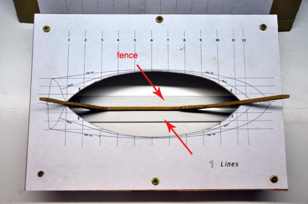
-
Symiaki Skafi by stelios
stelios replied to stelios's topic in - Build logs for subjects built 1851 - 1900
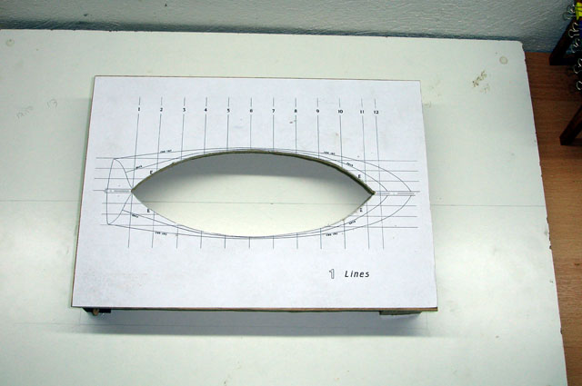
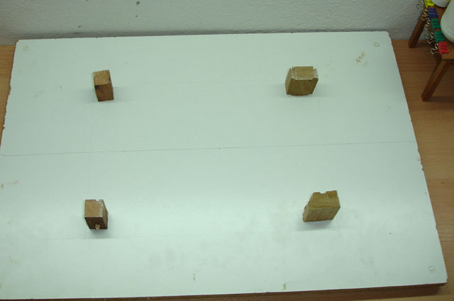
THE DRY DOCKS (adapted from the initial post) These are the first two pictures of this project: The jig is not ready yet, in order to secure the keel in vertical postition in relation to the board, a metal guide will be fit on the board to serve as a fence. Stelios

-
Symiaki Skafi by stelios
stelios replied to stelios's topic in - Build logs for subjects built 1851 - 1900
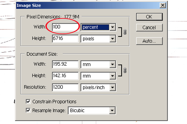
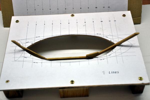
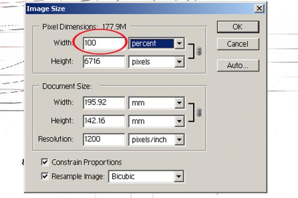
Bringing the plans to the desired scale. The first stages of the project one may say they are not that exciting as one must deal with a lot of research, and preparatory work. One of the most crucial steps in such a project is to bring the plans to the desired scale. It is crucial, because plans from different sheets must be resized and brought at the same proportions. In my case I had to resize 6 different sheets (scanned copies from a book). The program I used is Adobe photoshop, however I’m sure the same process can be run with a similar software. The steps below were followed for all pages: Print a copy of the plan at 100% scale. If the plan does not fit within the paper size, make sure that the legend of the plan is within the print area, as it is the element that will assist us to resize the plan. Take accurate measurement of the legend. I used the callipers, as it can give me a measurement with a good precision. To figure out the resizing percentage I used basic arithmetic: If for example, the 6m actual size corresponds to 42.8 mm on the printed plan, then at 1:50 the 6m actual size corresponds to 120 mm. The ratio 120/42.8 equals to 280.37% which will be used as the resize parameter in Photoshop. Each resized picture was saved with a different name (to preserve the original one). The next step was to print the resized image and verify that the scale is correct. As I do not have other than a standard A4 laser printer, I print only the area with the legend. With the aid of a scale ruler I verified that the new plan was correctly resized.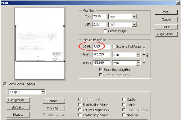
-
Symiaki Skafi by stelios
stelios replied to stelios's topic in - Build logs for subjects built 1851 - 1900
Symiaki Skafi The most common type of sponge fishing vessel was Skafi and especially the one, which was usually built on the island of Symi. That type of vessel was very common in Symi since the beginning of the 19th century and by the end of the same century vessels of this type in the island were over 160. Skafi was a small vessel less than 15 m. L.O.A and a distinctive form. The length of its keel was about half of the L.O.A. The stern post was straight and inclining sharply forward, occupying more than 1/3 of the L.O.A. and bearing almost an equal length to that of the keel. The transom on the stern was inclining backwards and occupying less than half of the height of the stern post. The middle beam (M.B.) was about 2/3 of the length of the keel and about 1/3 to 1/4 of the L.O.A. The capacity of the boat was 40-50 tons. Skafi had an extensive draught and a very pronounced sheer. The profile of the middle frame-section of the vessel was like a double ended boat below the water level (V-shape) and like a boat with a transom on the part above the water level (the sides fairly parallel to a bow and buttock plan). Because of this special form of the hull and the extensive sail's area which was carried the boat needed a lot of ballast, usually composed of beach stones. The rigging of Skafi had several variations. The most complicated one was with a spritsail (mainsail), a main topsail and a main (course) sail on the mast, a mizzen on a small mizzen mast and a foresail, a jib topsail and a jib fore of the main mast. Alternatively the mainsail on some Skafi boats was a lateen instead of a spritsail. A simpler recorded version on a small Skafi from Symi was only with a spritsail, a foresail and a small jib, while on a small Skafi from Kalymnos only a spritsail and a forsail appeared. It is worth to mention the special use of the small steering sail (mizzen) on the stern of the skafi. As the boat had to follow slowly the diver that was connected to the boat by means of a rope, this sail, together with the wide rudder provided slow side movements of the boat when she casted anchor, with long line. The vessel had the ability to move very smoothly during diving or to stay on a certain position, despite the weather and the prevailing currents. This special and distinctive form however made sailing very dangerous. Sudden changes of the wind did cause a very unstable balance of skafi, since the hull's centre of volume had sudden and automatic repositioning. Most of the accidents concerning these boats occurred during sailing rather than diving for sponges. Skafi - from the maritime museum of Symi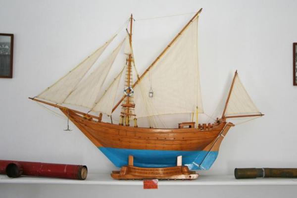
-
Sponges and sponge fishing were well known in the ancient times and they are mentioned in several documents of the Greek classical literature. From the 19th till the first half of the 20th century the sponge fishermen were coming mainly from the Dodecanese islands (Kalymnos, Symi, Kastelorizo, Chalki, Leros, Patmos and Astypalea), from Asia Minor (Kidoniai (Ayvalik), Krini (Tsesme) and Alikarnassos (Bodrum)), as well as from the Argosaronic Golf (Hydra, Hermioni, Spetses, Kranidi, Aegina, Piraeus). Trikeri, Chalkis, Oropos, Paros were some other islands in the rest of the Aegean and the island of Kutalis in the Sea of Marmara were also known for their sponge fishermen. The eastern Mediterranean basin and the northern African coasts were the main sponge fishing areas. The sponge as a commodity was highly appreciated amongst the people, throughout the centuries. The industrialization in Europe increased drastically the demand. It is therefore obvious why the fishing and export of sponges contributed substantially in the local economy for many islands as late as the middle of the 20th century. Sponge fishing was a special trade carried out by highly skilled and experienced divers and it required special types of vessels, suitable to support the sponge gathering from considerable depths in the sea. The sponge fishing vessels can be identified into two groups, depending on their use. The vessels used without any diving activity (e.g. trawling for sponge fishing or harpooning) belonged to the first one, while the vessels equipped for sponge diving belonged to the second group of vessels. “Symiaki Skafi” belonged in this second group. There is a third group of vessels called “depozito” or “bageto” which were not of any specific type of hull and they were used as supporting and supplying vessels to the divers and the crew of the sponge fishing vessels.