HOLIDAY DONATION DRIVE - SUPPORT MSW - DO YOUR PART TO KEEP THIS GREAT FORUM GOING! (Only 24 donations so far out of 49,000 members - C'mon guys!)
×

Richard Braithwaite
-
Posts
220 -
Joined
-
Last visited
Content Type
Profiles
Forums
Gallery
Events
Everything posted by Richard Braithwaite
-
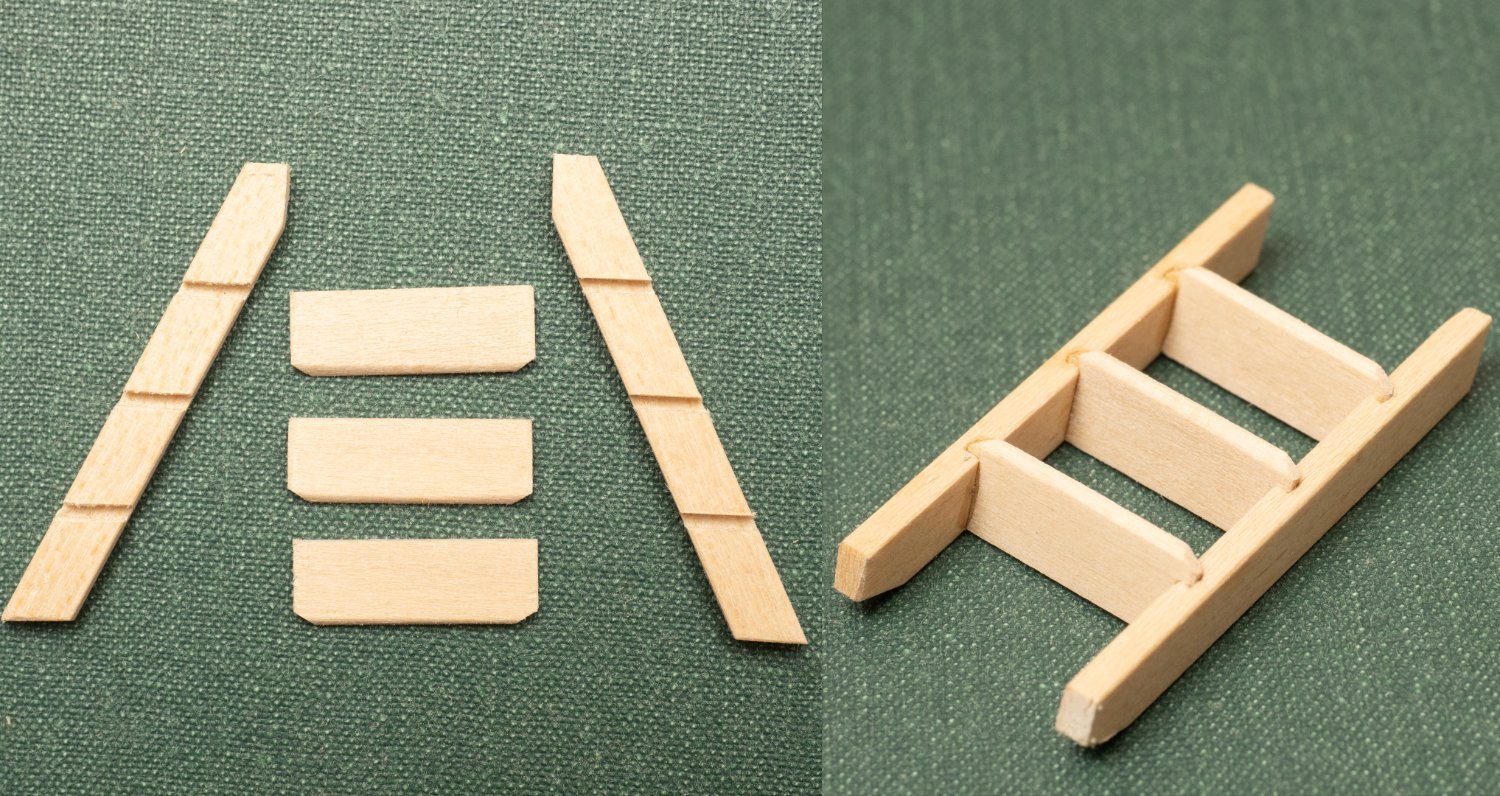
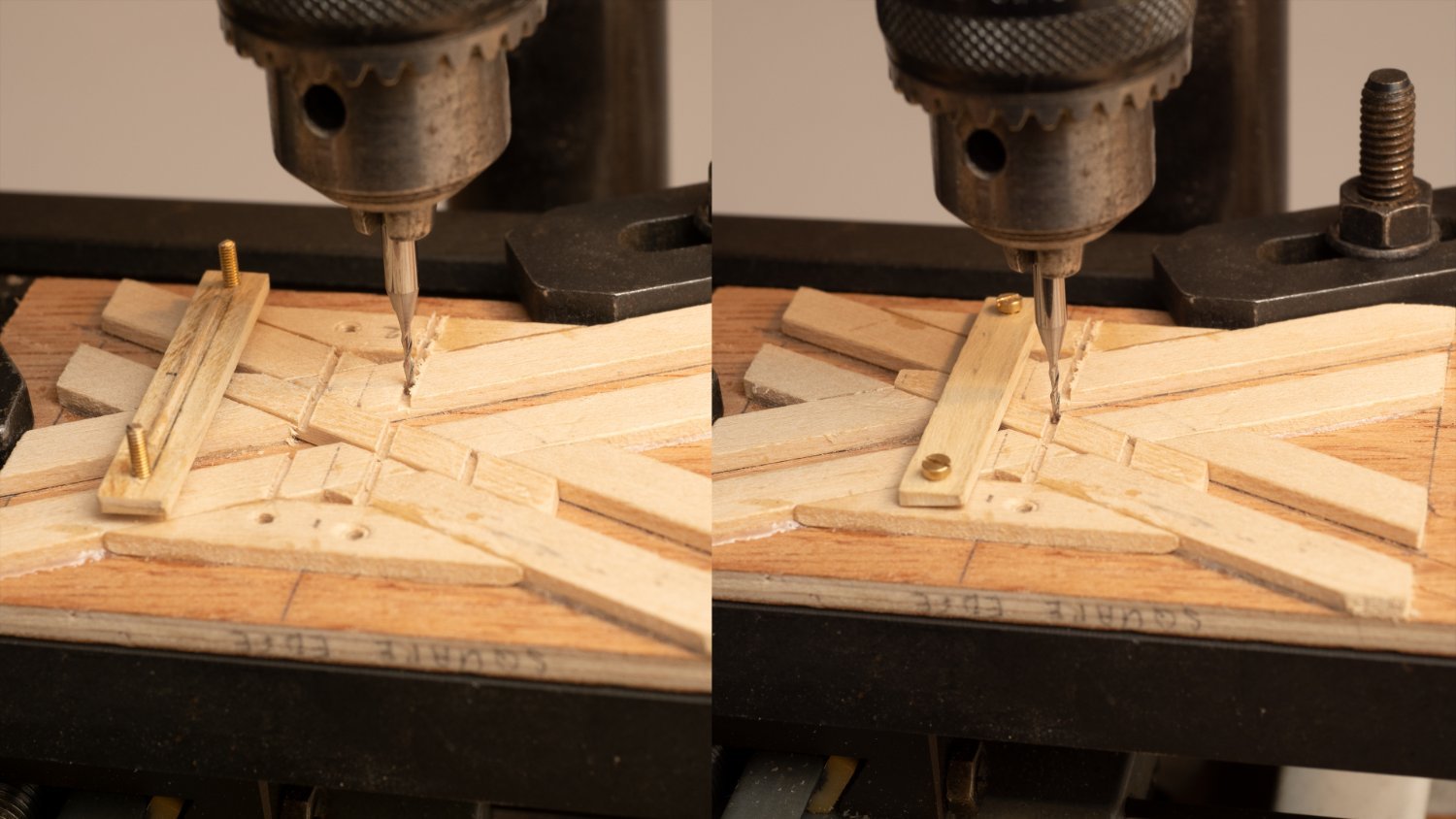
 I've got 4 ladders to build and have constructed this jig for cutting mortices for the rungs. Essentially one cuts the first mortice and then uses the jig to hold the side of the ladder in place while the next one is cut ... .
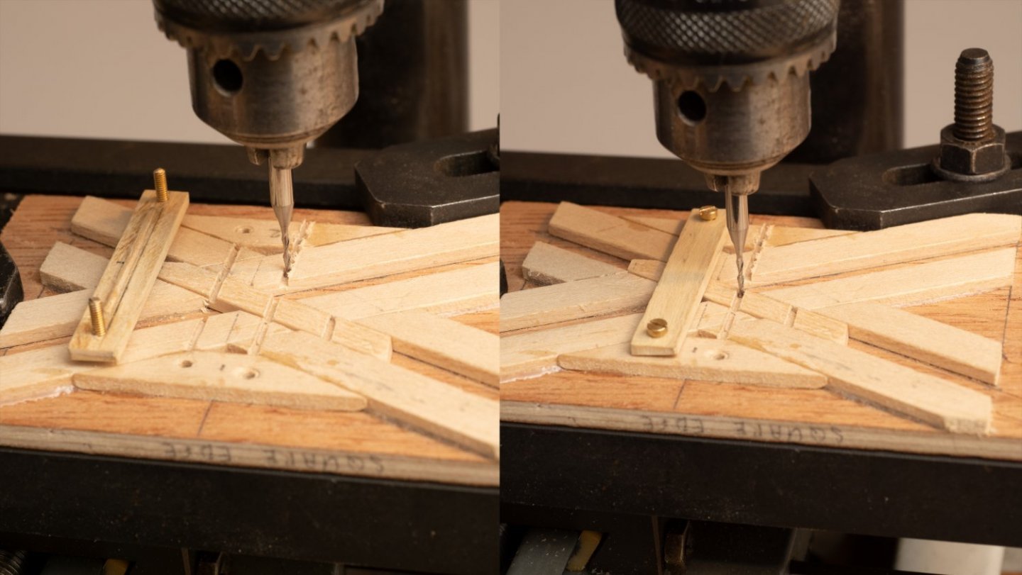
-
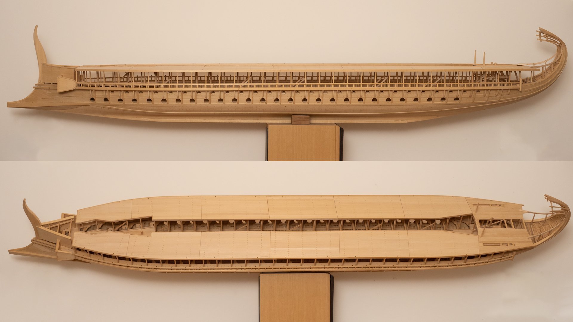
Will get round to the rigging in the end... Don't think I will make sails though. My main interest is in the oar system...
-
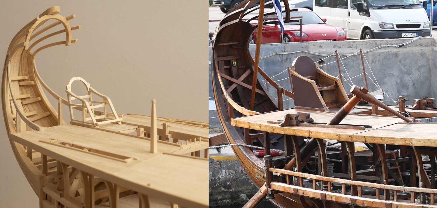
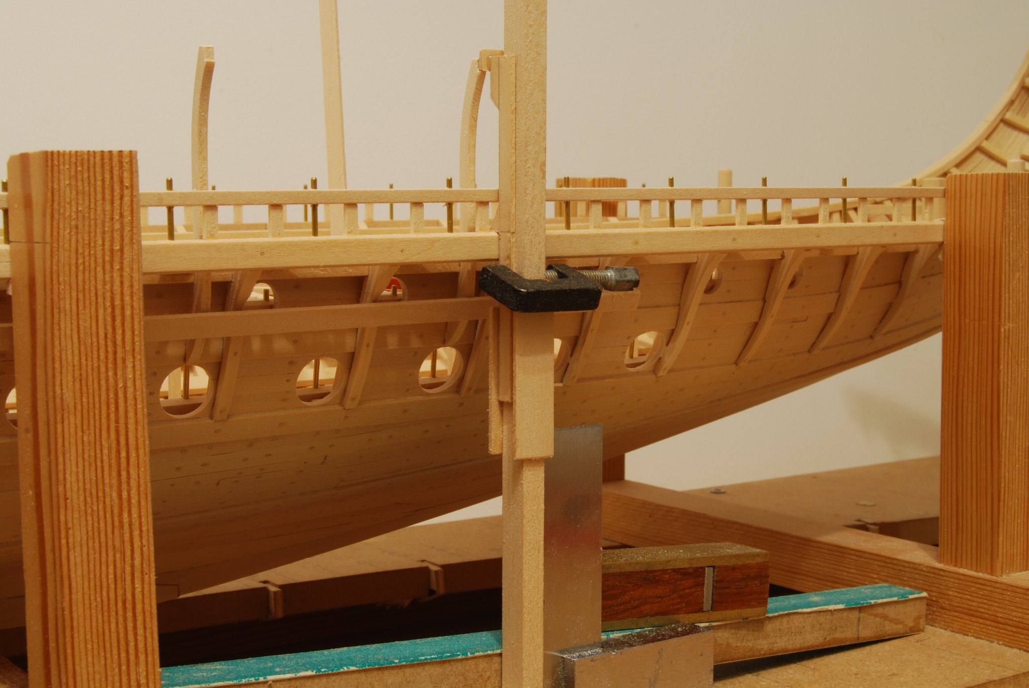
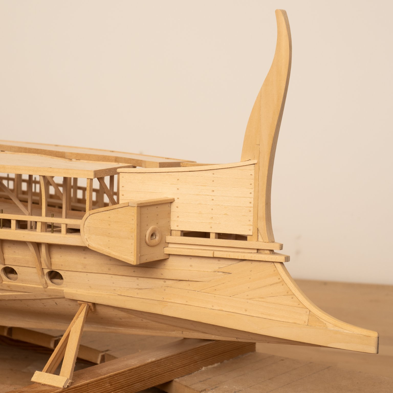
A view of the seat frame located on the quarterdeck compared with a picture of the full size Olympias. I have built my model as closely as possible to Coates design drawings (the drawings sheets contradict one another in some cases - as you would expect from what was essentially a prototype for a reconstruction of a warship which hasn't been built in living memory...). These include: 1.Differences in framing of the stern. 2. Removal of the footrest from the Trierarch's chair. 3. Differences in the leather upholstering of the Trierarch's chair. 4. Removal of the handhold post at the head of the ladders from the quarterdeck to the gangway. 5. Additional bracketry alongside the steering oar slots. I am sure some of these changes were incorporated at build and others were introduced as sea trials progressed. Not unlike my own experience of designing and building modern ships!

- 300 replies
-
- 13
-

-

-
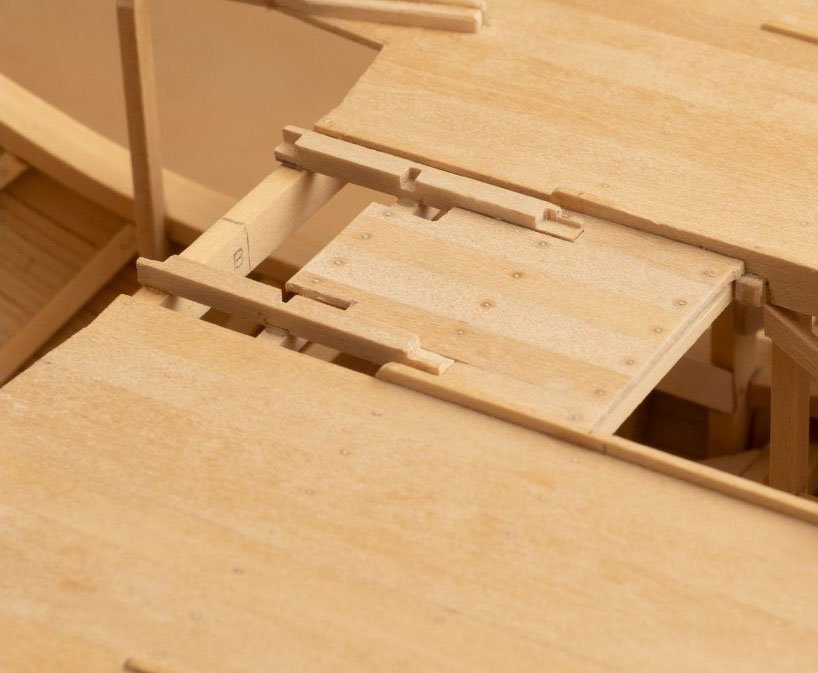
Seating for the seat (?) installed on the quarterdeck. I've taken a piece out the planking between the morticed longitudinals to allow the seat to be lashed down the to the deck as shown in the trireme seat drawing. This differs from the drawing of the quarterdeck (extract shown below with the photo of my model) which would not have allowed for the seat to be lashed down in this way.
-
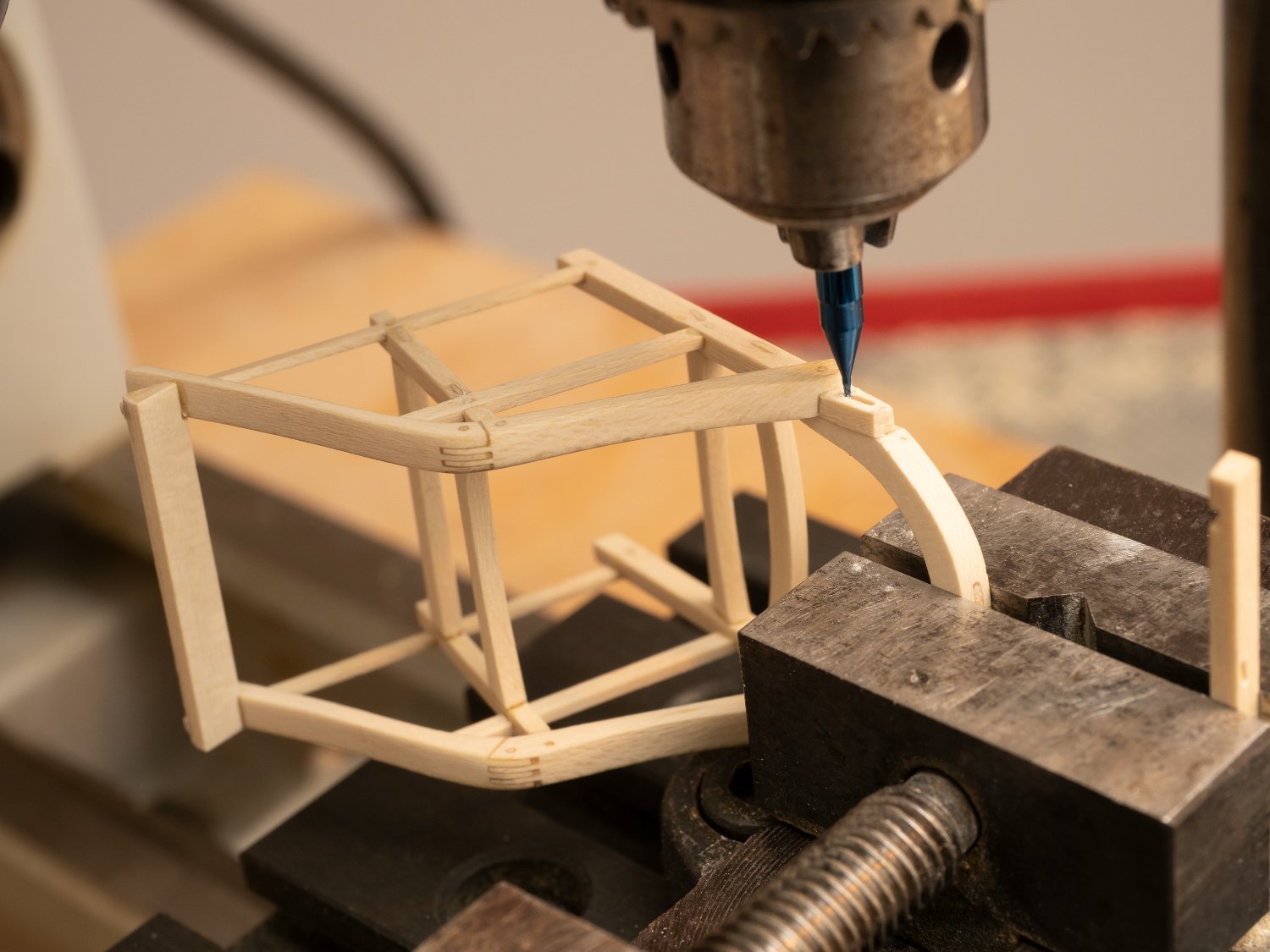
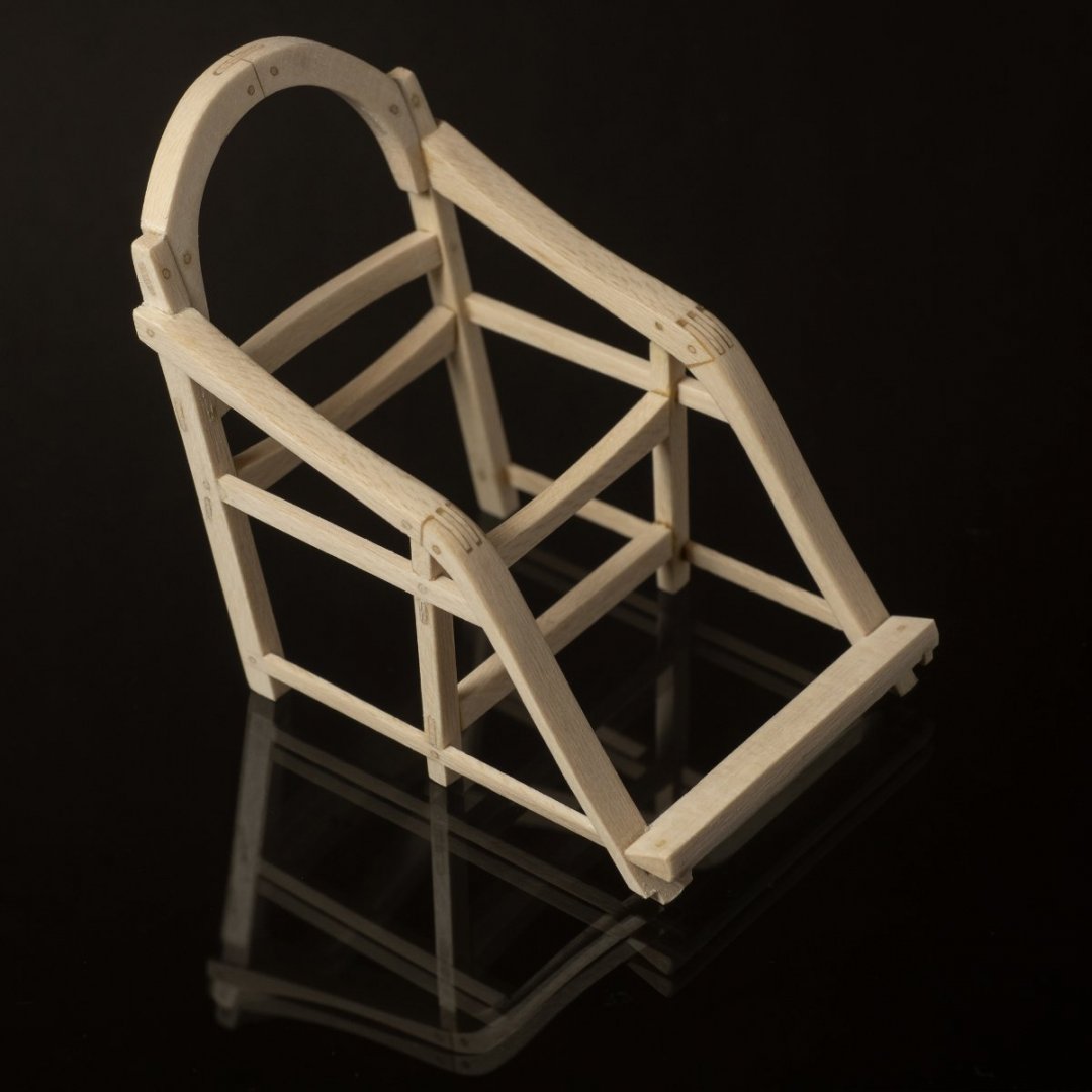
Completed chair frame. Not perfect by any means, but the smallest pinned mortice and tenon joints I've ever tried! At 1:24 the chair is about 1 inch wide. I do like the grain on holly...really fine... almost like 1:24 oak!
- 300 replies
-
- 14
-
-
-
Really interested to see how this turns out. My rowing machine is fairly primative in that it describes a constant speed elliptical orbit and will not follow how an actual oarstroke would work when operated by a real human being (particularly during the acceleration phase from a stationary start...) I have been doing some research into this and writing some simulation code (in C++ for speed of execution). the purpose of this exercise is not to support any rowing machine but to gain an greater understanding of oared warships and how they could have been optimized in design. Some time ago I found a paper online describing a rowing machine model that used a weighted pully system so that the pressure applied during the power stroke (when the oar blade is in the water) is constant from catch to finish (cant find the reference now...) which I thought might be quite interesting..
- 536 replies
-
- 2
-
-
- Quadrireme
- radio
- (and 1 more)
-
I have a load of Meccano that I inherited from a cousin years ago. Made various things with the kids over the years but hadn't thought of using it for rope making machines etc.
-
Probably an excessive investment in time given what a minor component this chair is of the overall model....But I've found it an interesting challenge to see what I can achieve with a hard, fine grained wood and a Unimat lathe/milling machine.. This project has been going on for so long now that I tend to see it as a series of sub projects and get my satisfaction from each of them rather than targeting overall completion... Hopefully, Ill get there one day, but then Ill have to find a rather large area of the house to keep the model!!
-
Armrest construction for the Trierarch's chair. Ability to dial in the positions for this complex joint really helps at this scale

-
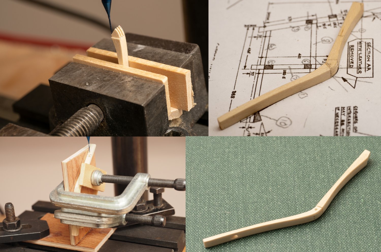
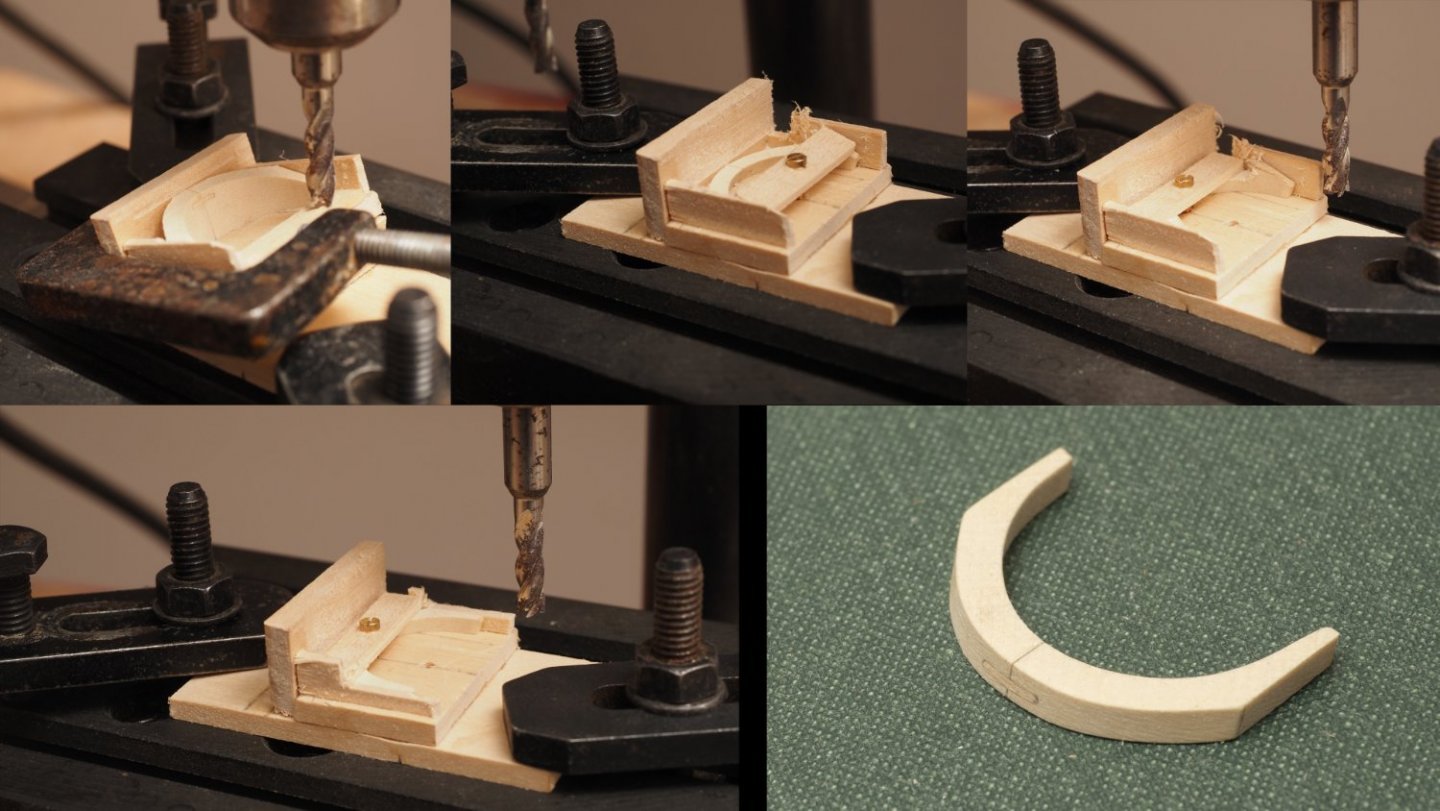
Continuing with the Trierach's seat back. Photos in order from top left: 1. Seat back reoriented in jig. Shown after the rear face has been machined. 2. Jig altered to take out the 20 degree angle so that the front face can be machined parallel to the rear face. In order to hold the piece down I designed the jig with two clamping positions. This photograph shows the first clamping position which allowed the top half of the front face to be machined. 3. Clamp moved tot he second position so that the bottom part of the front face could be machined. 4. Front face completely machined 5. Completed seat back. As the maximum dimension of this part is only 23mm I think I would have struggled to make it without the help of my Unimat🙂
-
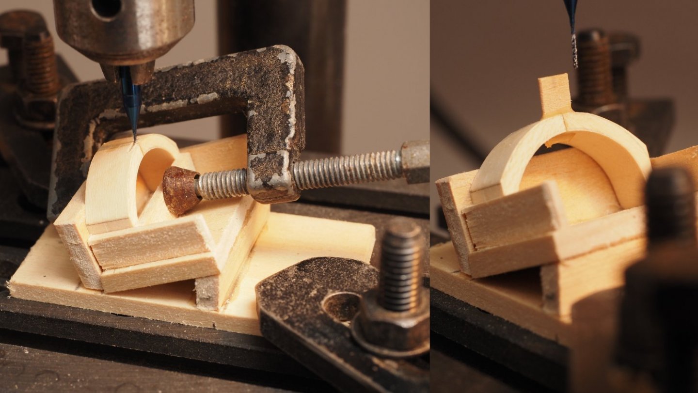
Continuing to machine the seat back... Built a simple jig to bolt to my Unimat milling table to incline the seat back at 20 degrees so that the slot for the tenon connecting the two halves could be milled...
-
Richard, I've also spent many years developing hullforms as a Naval Architect in England. Rhino is a great product, which I find really intuitive and easy to use. My main application was developing early stage concept design of warships and then rendered them using the addin renderer flamingo. My workflow generally involved developing the hullform in Paramarine and then importing the iges surface into Rhino to develop the superstructure and detailed 3D model for visualization. Main reason for doing it that way was because we needed the Paramarine model for sizing and analyzing the design before we reached the stage that we wanted a more detailed 3D model. Paramarine is slightly painful for use for generating hulls (although you can get proficient in just about anything if you really have to!!!). Rhino is also a lot less expensive to buy. Looking forward to seeing how you go about hull modelling in Rhino BTW Have you ever tried the Rhino addin ORCA?
-
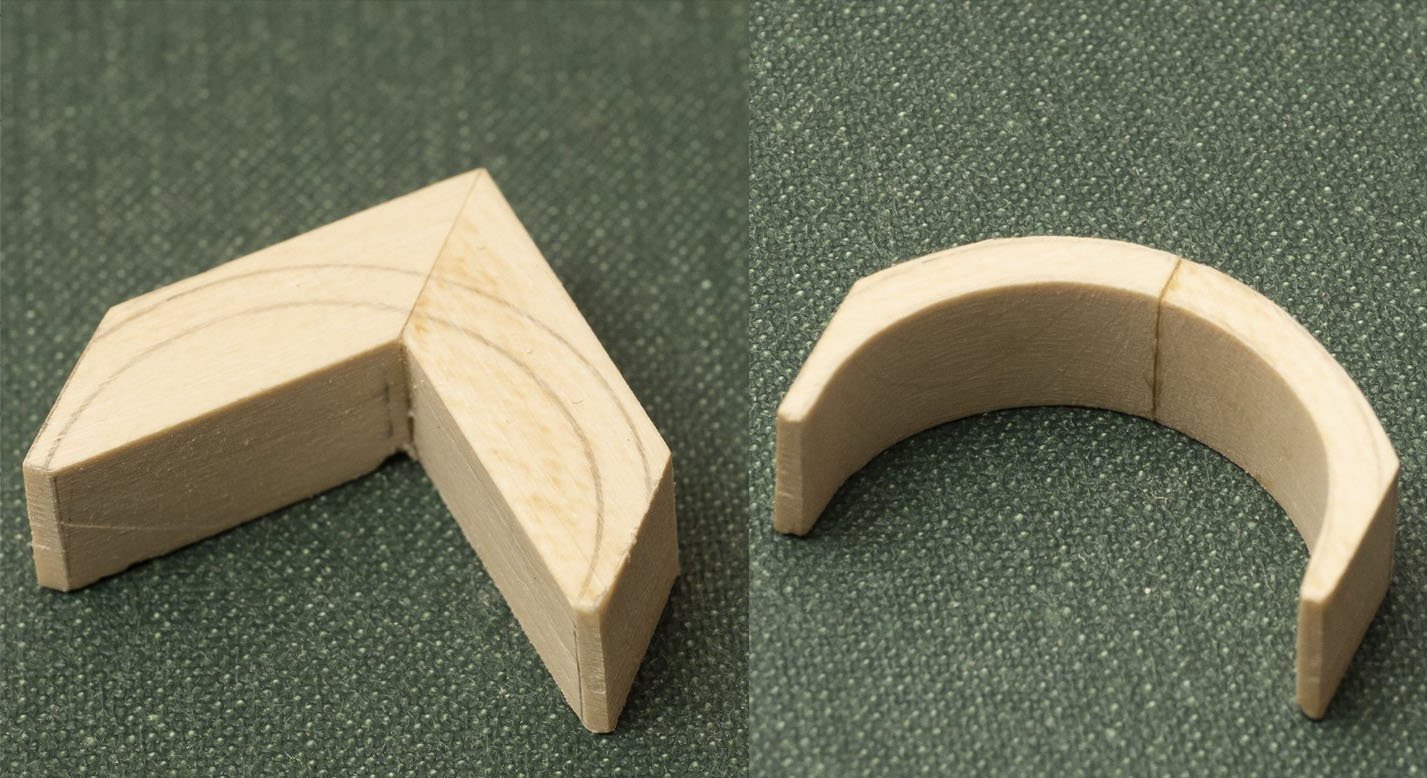
First pic shows seat back machined on Unimat and second pic shows the outer and inner radius shaped by hand... The piece is deep enough for me to cut the rake of the seat back. I think I will cut the mortice and tenon first to give the join some strength and then work out how to mount it on my milling table to cut the rake...
-
I think you may be right. With my 100mm saw blade I can do a deeper cut. So I don't think you will be exceeding the spec if you can make the cut. It wont cope with a 5 foot long 1 inch thick holly plank though, so at some point I shall have to get/borrow a larger saw to cut some usable pieces for model building.
-
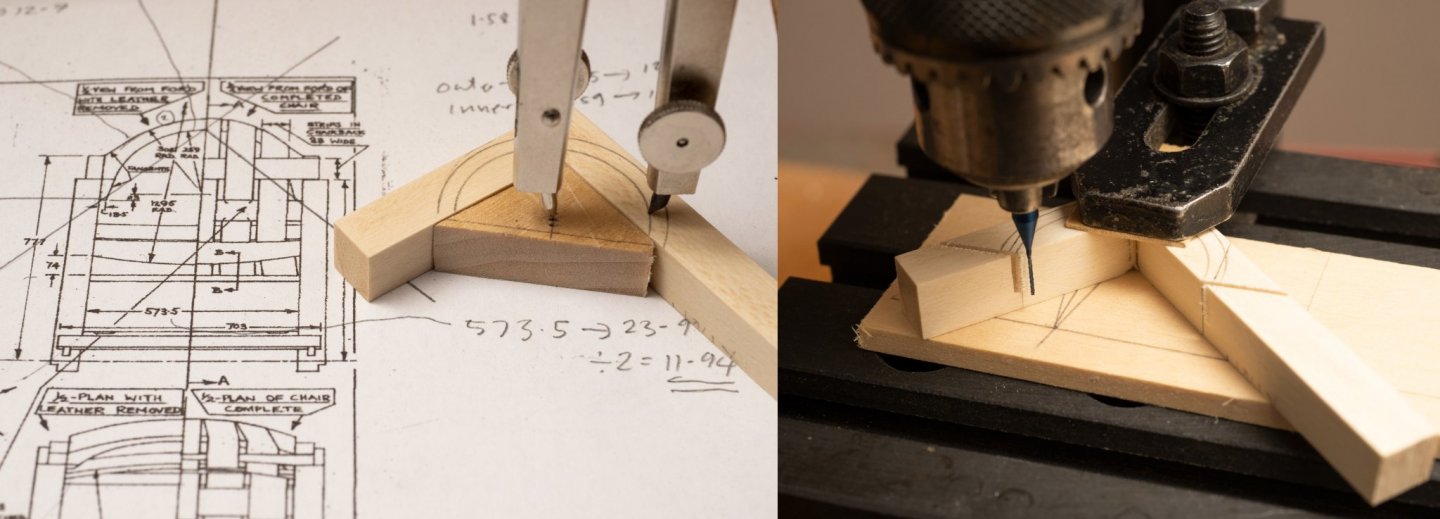
Marking out and machining the chair back timber. I've purchased a set of 0.5mm engraving end milling tools which I'm using here to cut the base of the back and accurately cut the sides so that the width of the chair will be correct. As you can see the tool is very slender and delicate, I broke one by being overambitions about the depth of cut (0.2mm cut and a slow steady feed is tops for a hard wood like holly...). The cutting part of the tool is only 5mm long so I had to finish the cuts with a saw (maximum cut shown in the picture), but still a great improvement over me trying to do it freehand... m also hoping to use the tool for cutting mortices for the various joints as its is the right size
-
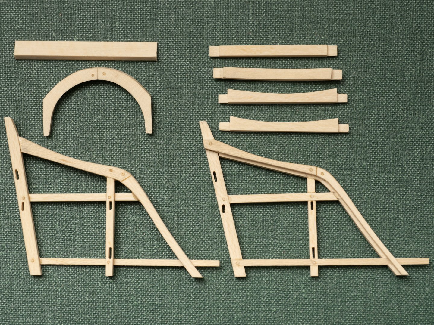
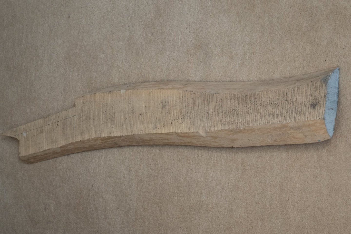
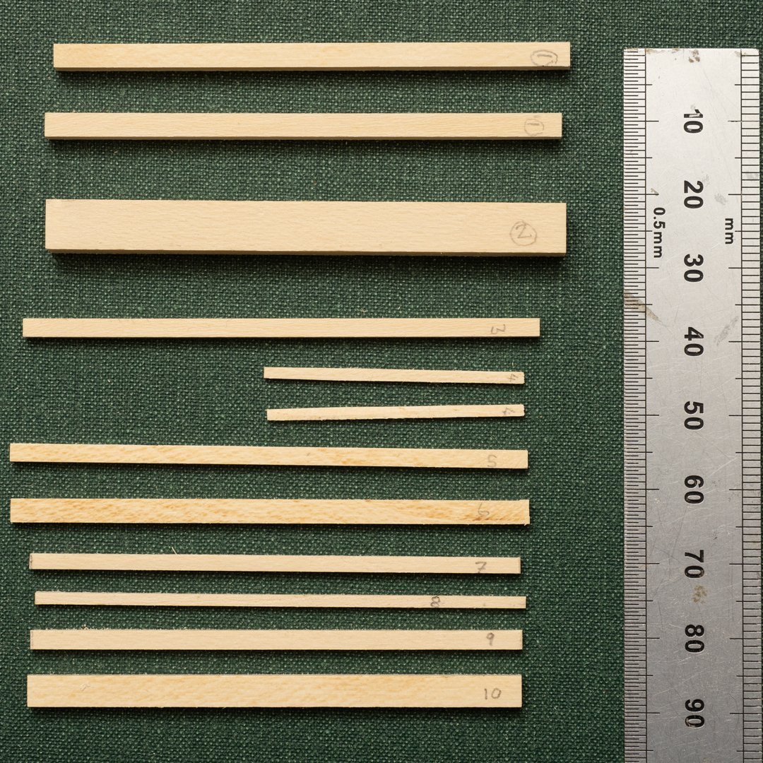
I am using holly for constructing the Trierarch's chair. Its a remarkably fine grained hard wood that can be machined rather like a soft metal such as aluminium and I hope to be able to mill scale joints in accordance with the drawing. I have a large amount of holly from an 8 inch diameter tree that I cut down about 30 years ago (!!). I cut the (5 foot) log into 1 inch planks, painted the ends and stacked them to dry out in our garage. As you can see from the picture below they warped a bit while seasoning, which makes it a bit awkward to cut pieces from it, particularly as my circular saw (https://www.byrnesmodelmachines.com/) can only cut a maximum depth of 15mm...so I've been cutting chunks out of it with a handsaw... Here are some timbers machined to size from this log ready for final shaping and jointing to make up the various components for the chair.
-
Pat Thanks for the comment. Yes I was thinking that split pigskin lining shaved down might work. It needs to be about 0.25mm thick to fit in the recess in the arms of the chair...
-
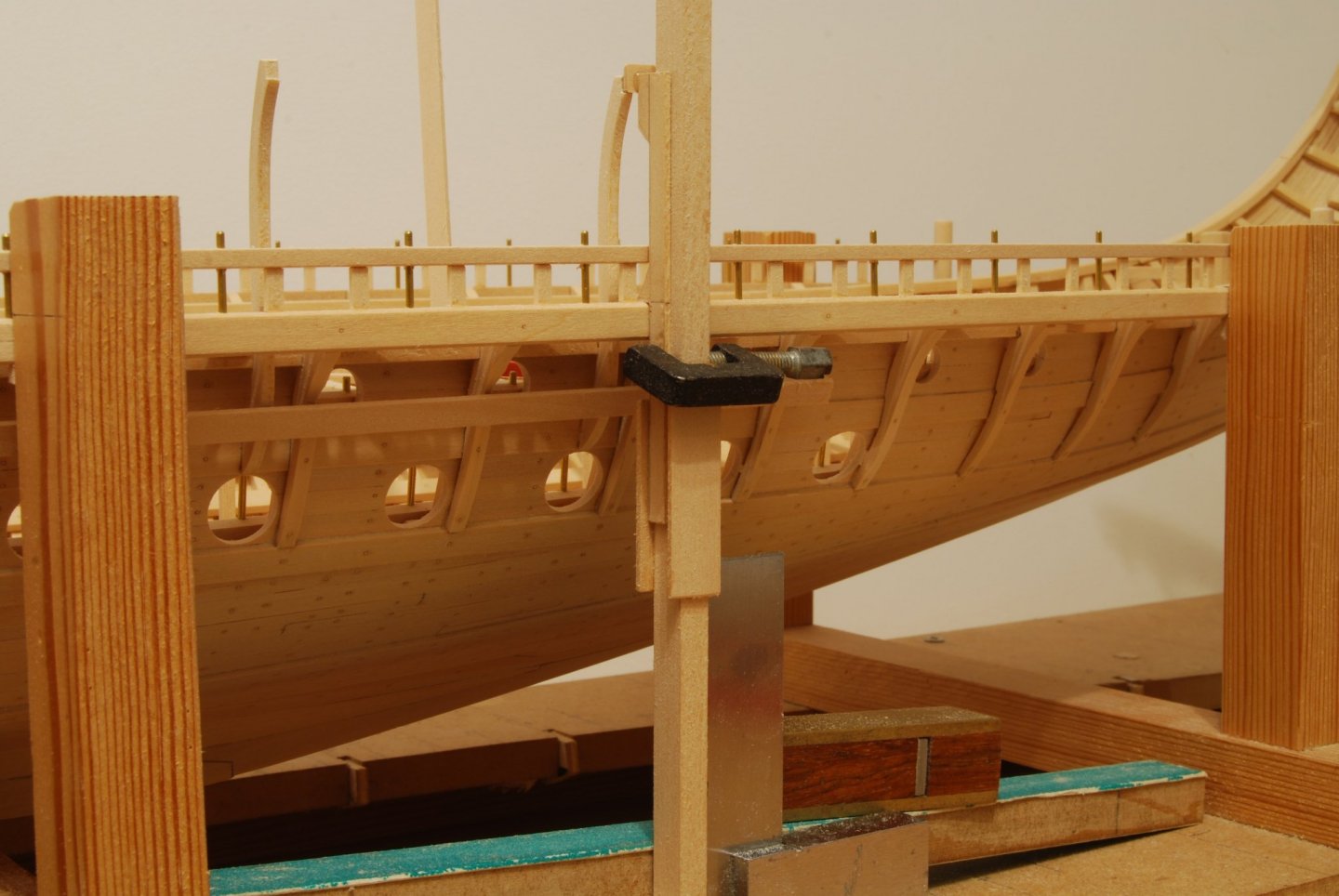
Unfortunately the shape of the hull changes so that these timbers have to be shaped individually. I used the jig shown in the photo below to ensure that the outer canopy supports would line up with vertically above the outrigger at the correct height...I cant find a photo of the arrangement I used for the outrigger supports, but the issues are very similar...
-
I like the idea of controlling oar position with software as it allows experimentation with different oar paths and velocities...I've also been developing some rowing machinery for my trireme model. My prototype does not use software to control the position of the oars, but drives the oars (port and starboard independently) in a simple, sinusoidal, elliptical orbit which enables the oar handle path to fit within the close constraints of the trireme structure. Video of prototype in action below:
- 536 replies
-
- 4
-
-
- Quadrireme
- radio
- (and 1 more)