
Richard Braithwaite
-
Posts
229 -
Joined
-
Last visited
Content Type
Profiles
Forums
Gallery
Events
Everything posted by Richard Braithwaite
-
 Dan (dicero) has kindly invited me to do an online presentation on this project for the NRG on October 11. I'm planning to include the background to the project and the construction of the hull, which all came before I started this build log and will do my best to answer any questions you have.
 -
Really spectacular. Fantastic craftsmanship. Well done
-
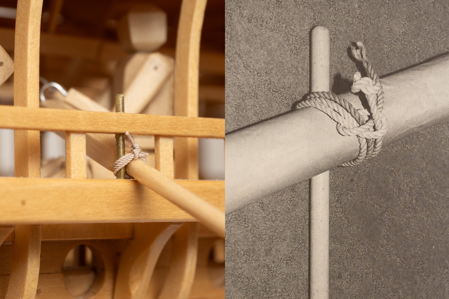
I've been thinking about how to secure the oars to the thole pins. During the first trials leather loops were used, but these tended to stretch as they got wet so in 1994 an adjustable rope grommet was introduced on the advice of a Poros fisherman (Ref The Athenian Trireme, Coats et al). I have used some thinned down leather for my steering oar bearings but am not sure of the longevity of using real leather in this application so will probable go with the 1994 rope version. Here is its using Ben's 0.5mm polyester rope (12mm full scale), which seems about right. In the Illustration "the stopper knot at one end of the grommet has been pulled clear for clarity". Mine is pulled up tight... Still getting to grips with this small scale ropework. One of the things I've realised is the amount of wastage one requires, just to give you something to hold onto. Its very fiddly stuff! I'm going to have to order some more rope to make sure I have enough...
-
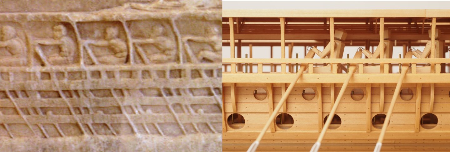
My three marines doing their best to model the Lenormant Relief... (it will be some time before they are joined by the lower oar banks...)
- 319 replies
-
- 11
-

-

-
62 Thranite oars completed... Roughly positioned on the ship (resting on a piece of glass at approx waterline...)


- 319 replies
-
- 13
-
-
-

-
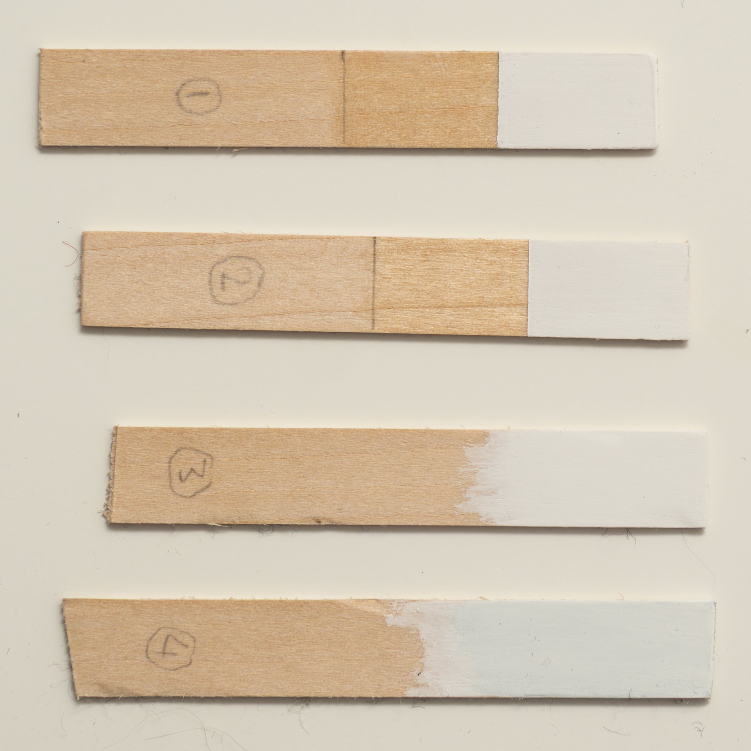
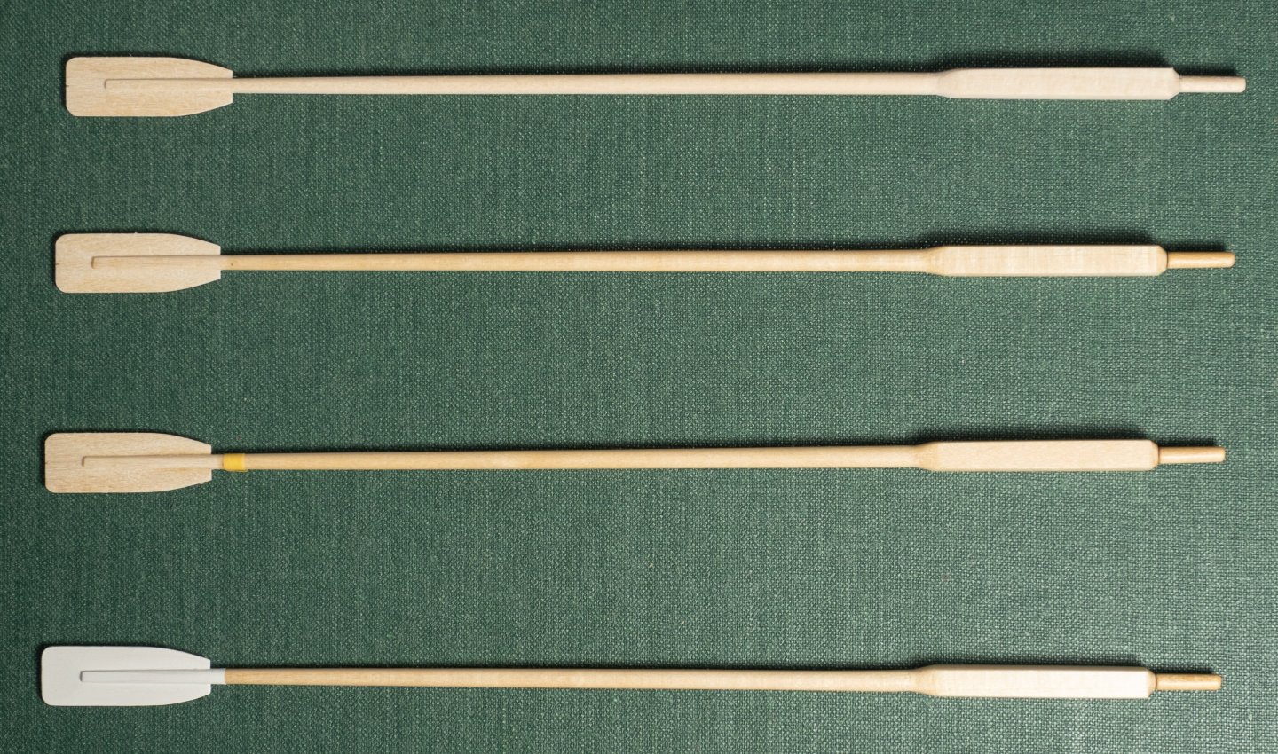
Oar Painting step by step... From the top: 1. Unpainted oar 2. 3 coats of matt polyurethane varnish (thinned 25%) on shaft. 3. 3mm Tamiya masking for blade area with 1 coat of poly varnish (thinned 25%) on edge to prevent bleed. 4. Blade painted with 1 coat BIN primer and 2 coats of white enamel (thinned 25%)
-
Yes the philosophy throughout has been waterproofness, hence use of expoxy for bonding and polyurethane for sealing. But aesthetics are just as important (probably more so now, given how much further Ive ended going with this model than I origianlly envisaged...)
-
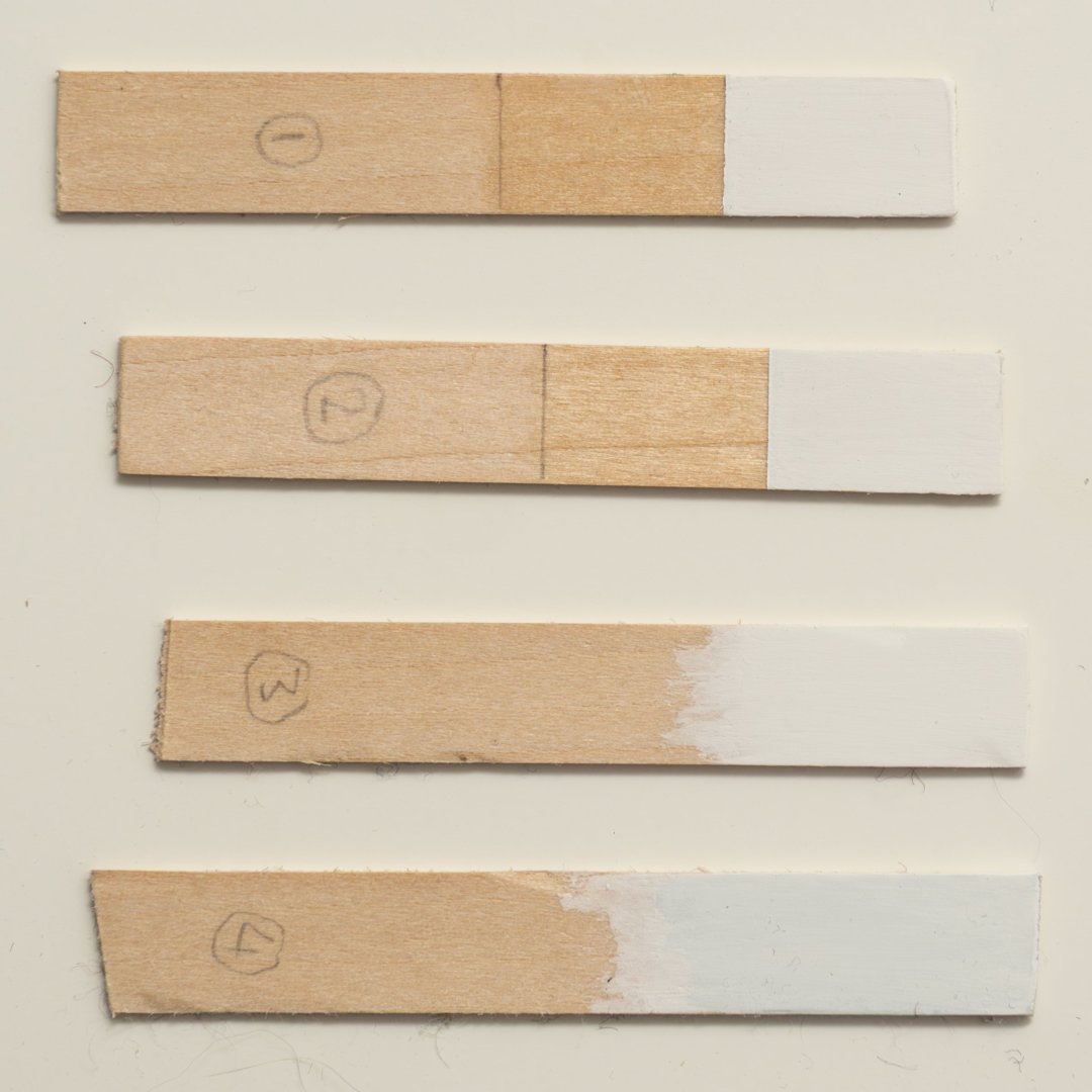
An exciting post about paint! I need to coat my oars. Shafts varnished and blades painted. Products Ive tried below: Four different trial combos below. 1. 4 coats of varnish just belond the boundary. 3mm Tamiya masking tape at boundary (with a varnish seal along edge) then 1 coat BIN primer (on bare wood) and 3 coats white matt enamel. 2. 4 coats of varnish over bothe areas. 3mm Tamiya masking tape at boundary (with a varnish seal along edge) then 1 coat BIN primer (on top of varnish) and 3 coats white matt enamel. 3. 3 coats white matt enamel on bare wood. 4. 1 coat Humbro undercoat (on bare wood) and then 4 coats of white matt enamel. The grey Humbrol undercoat seems to need a lot of coats of white enamel to cover it (it still looks a bit grey with 4 coats). Apparently the shellac in the BIN undercoat will slow the discoloration of the white paint by blocking any oils coming out of the wood, so Im probably going with option 1...although it seems a shame not to use the Humbrol Undercoat with the Humbrol paint...

-
Some statistics for the oars at this stage (i.e. shaping complete prior to painting) WEIGHT: So my oars scale at 11.71 kg/oar (without the brass pin from the handle) compared to 12.3 kg/oar on the full size Olympias (without the lead counterweights in the handles), so within 5%. The density of the wood Ive used is similar to the density of the Douglas fir used for these oars on Olympias, so that suggests that Ive got the dimensions about right (the weight will be even closer once Ive painted/varnished them...) LABOUR: So, to get to this stage has taken me 3.25 hours per oar (still to paint them...) which excludes the time I took to make the jigs, do trial runs etc... Duration wise its taken me about 4 months to make 62 of them which sugests that Im working about 1.7 hours per day on average. Its probably a bit more than that (given jigs etc.)...Probably about right, given Im not allowed to do this every day! Just to put this in perspective the cost of an oar for Olympias in 1987 is quoted as £300 (ref the Trireme Trials 1988)


-
All blades fitted... Now cutting a radius onto two of the faces of that thickened part of the oar shaft inboard of the thole pins... I tried grinding a radius into a scraping steel plate for this but found it difficult to make an even cut along the shaft (and avoif grain pullout...). Cutting a piece of plastic pipe in two longitudinally and then lining with sandpaper, however seemed to work surprizingly well, giving a consistant radius down the length of this part of the shaft. The lines drawn accross the shaft in the photo below are used for guidance (all gone when radius cut) in the usual way I use for controlling shape of shafts and spars during shaping. (extract of Plans 15 © Estate of John F. Coates, reproduced with permission).

-
Excellent model of an interesting subject. The morticed planking is a feature also found in much older vessels such as the Kyrenia ship (4th cent BC) and is also thought to have been the construction method that enabled long slender ships such as the fast Triremes of the 6th century BC to be built (effectively stopping the planks from sliding over one another and making the planking into an effective engineering shell able to withstand the high sheer stresses in such a vessel). (Ref The Athenian Trireme, Morrison and Coates) Also interested to see that your rig has a similar system of brails as fitted to the Trireme reconstruction Olympias.
-
Waterline looks great. What material did you use? 1/4" acrylic?
-
Since turning the handle on this oar production line doesn't use up much mental bandwidth I've been listening to podcasts as I go. I've been finding the style of "The Rest is History" just about the right level to make the hours fly by... They have done a good series that gives the historical background to the significance of the Trireme in enabling the golden age of Athens and the development of their democracy, philosophy and art that has influenced Western Civilization so significantly in the centuries that followed. Thermopylae and Salamis: Athens and the Birth of Democracy: Herodotus, the birth of history: Sparta:
-
Gold solder for brass
Richard Braithwaite replied to Richard Braithwaite's topic in Metal Work, Soldering and Metal Fittings
Or, I suppose one could use silver solder and then get the whole thing gold plated! A nice consistent colour finish? (if a little shiny...) -
I actually find this production line stuff quite theraputic. Once all the thinking is done and I know what im doing I can just sit in my workshop and go through the motions, one after another. Not so much of an issue now Im retired, but I used to find it very relaxing after a stressfull day at work!
-
Gold solder for brass
Richard Braithwaite replied to Richard Braithwaite's topic in Metal Work, Soldering and Metal Fittings
This is what I need to make, its at 1:24th scale for my model of this Trireme ("Olympias") which makes its total length about 50mm. It fits over the wooden ram structure and will be about 0.5mm thick. Quite a challenge to fabricate, with a lot of joints...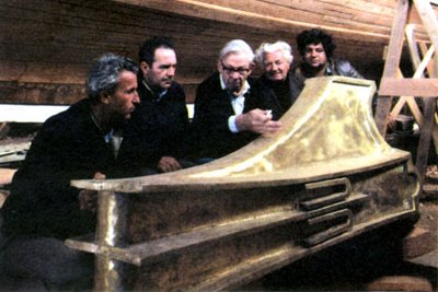
-
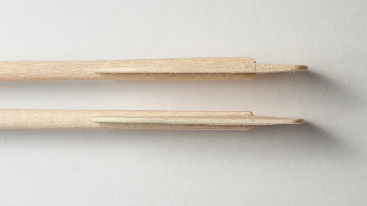
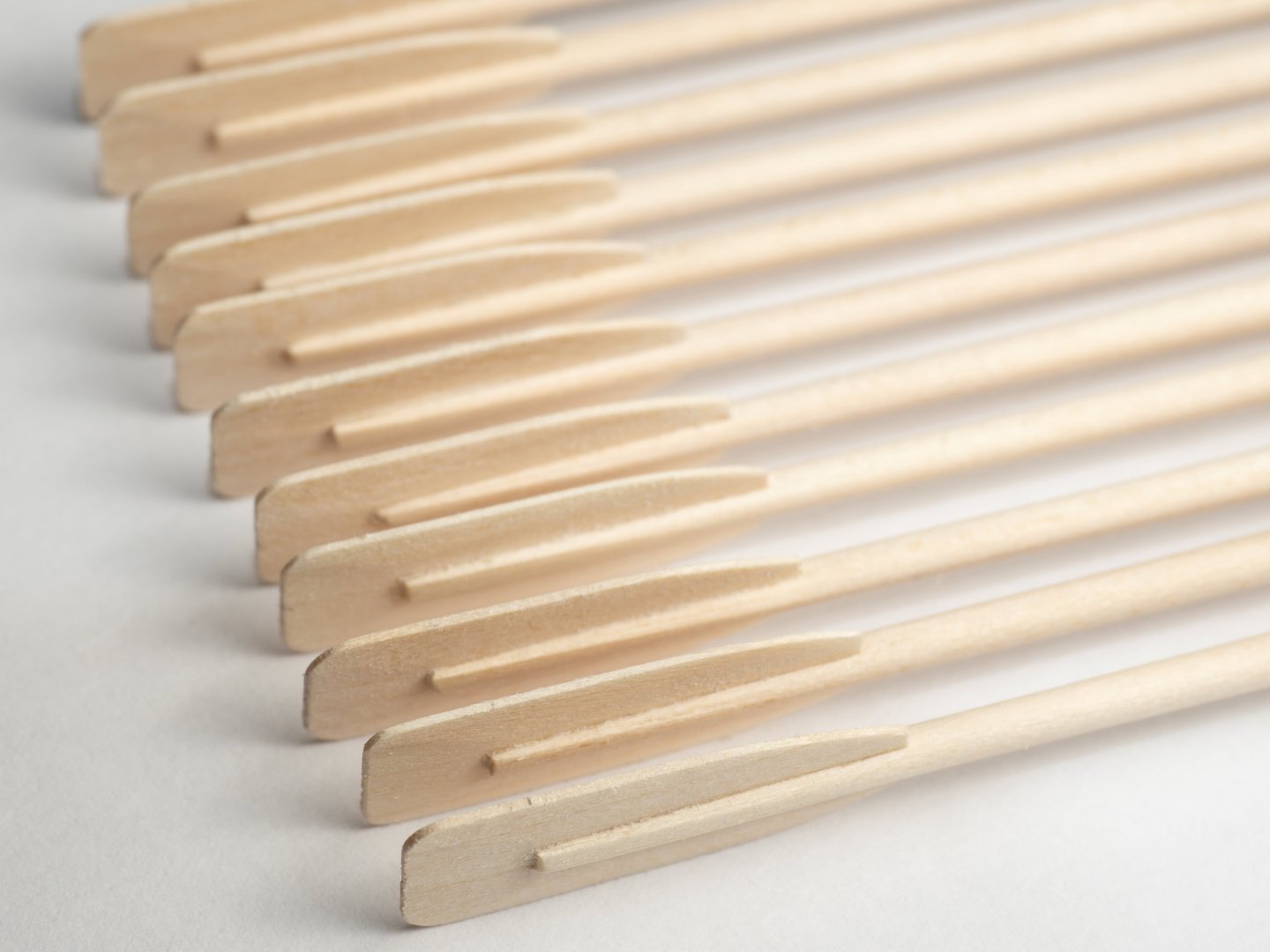
Next steps: Jig fixing tabs removed from blades and blades shaped to plan view using a ply template pattern (that same 0.5mm ply I was originally planning to use for the blades...) Blades fixed to oar shafts between prongs. As the slot between the prongs was milled to 0.5mm the prongs flare to accomodate the long taper on the blade (0.5 to 1mm thickness...) as can be seen in the upper part of the image below. Prongs tapered along the long taper of the blade to remove the flare (see sketch reconstruction of blades in previous post) the side taper (to bring the edges of the blade down to 0.5mm all round) was then done using a file and sandpaper by hand, as can be seen in the lower part of the image below. Total time taken for all this approximately 40 mins/blade. Quite a lot longer than just fitting 0.5mm ply blades and probably almost impossible to see the difference once they are finished and painted white, but so be it...
- 319 replies
-
- 10
-
-
Your silk rope is indeed spectacular!
-
Gold solder for brass
Richard Braithwaite replied to Richard Braithwaite's topic in Metal Work, Soldering and Metal Fittings
Yes (about £10/5cm length) but only small quantities would be needed... -
Gold solder for brass
Richard Braithwaite posted a topic in Metal Work, Soldering and Metal Fittings
Has anyone tried 9 carrat gold solder for brass? I guess it might give a better colour match? If so how does it age? (I.e colour of solder as surrounding brass oxidises and darkens) -
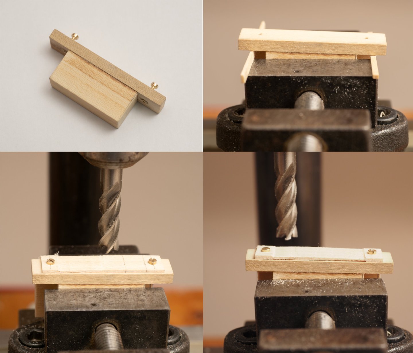
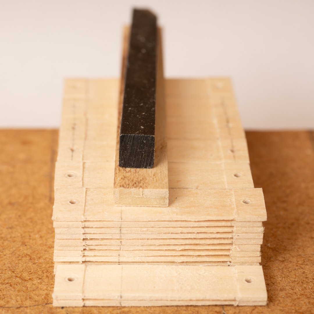
Tapering of oar blades: Image top left: jig, made of holly to make it (hopefully ) robust enough for use with all 62 Thranite oar blades. Top right: set up in machinists vice on Unimat with spacers cut to incline the top surface or the jig correctly for the taper to be cut. In hthis case it is set up for the short taper which means a 1.25mm difference over the 30mm length of the vice. (0.4mm difference for the long taper). Bottom left: Long taper being machined (both sides) Bottom right: Short taper being machined (both sides) Finally 62 Tranite blades tapered (about 16 mins/blade...)
-
The silk looks superb, unfortunately we have clothes moths here and anything I make out of natural fibres is instantly consumed!
-
Your rigging is spectacular. Im still in the early stages of working out what is possible and you seem to represent the limit. What material are you using for your rope? Those rope coils seem to hang very naturally.