
Richard Braithwaite
-
Posts
229 -
Joined
-
Last visited
Content Type
Profiles
Forums
Gallery
Events
Everything posted by Richard Braithwaite
-
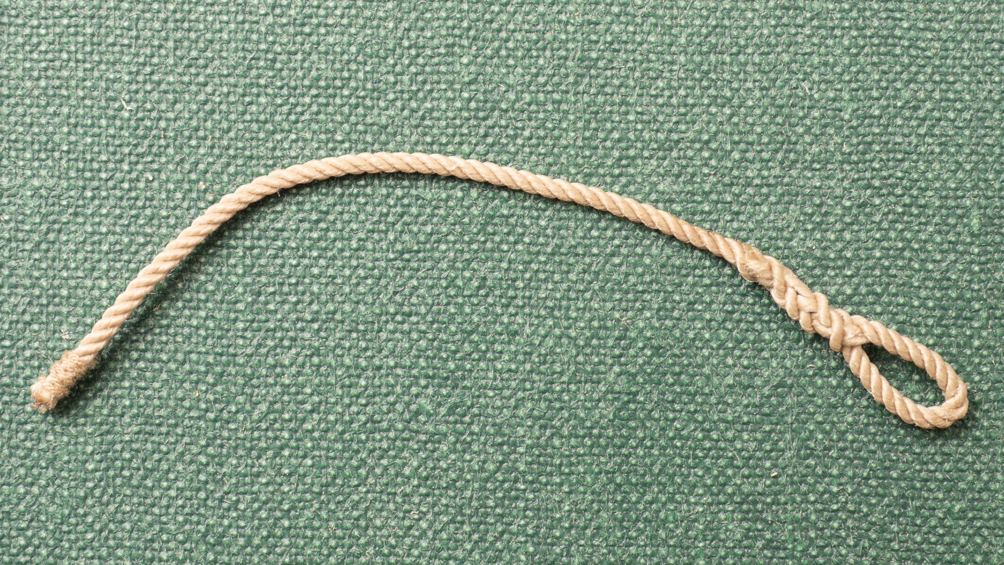
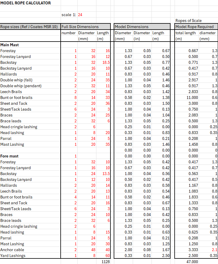
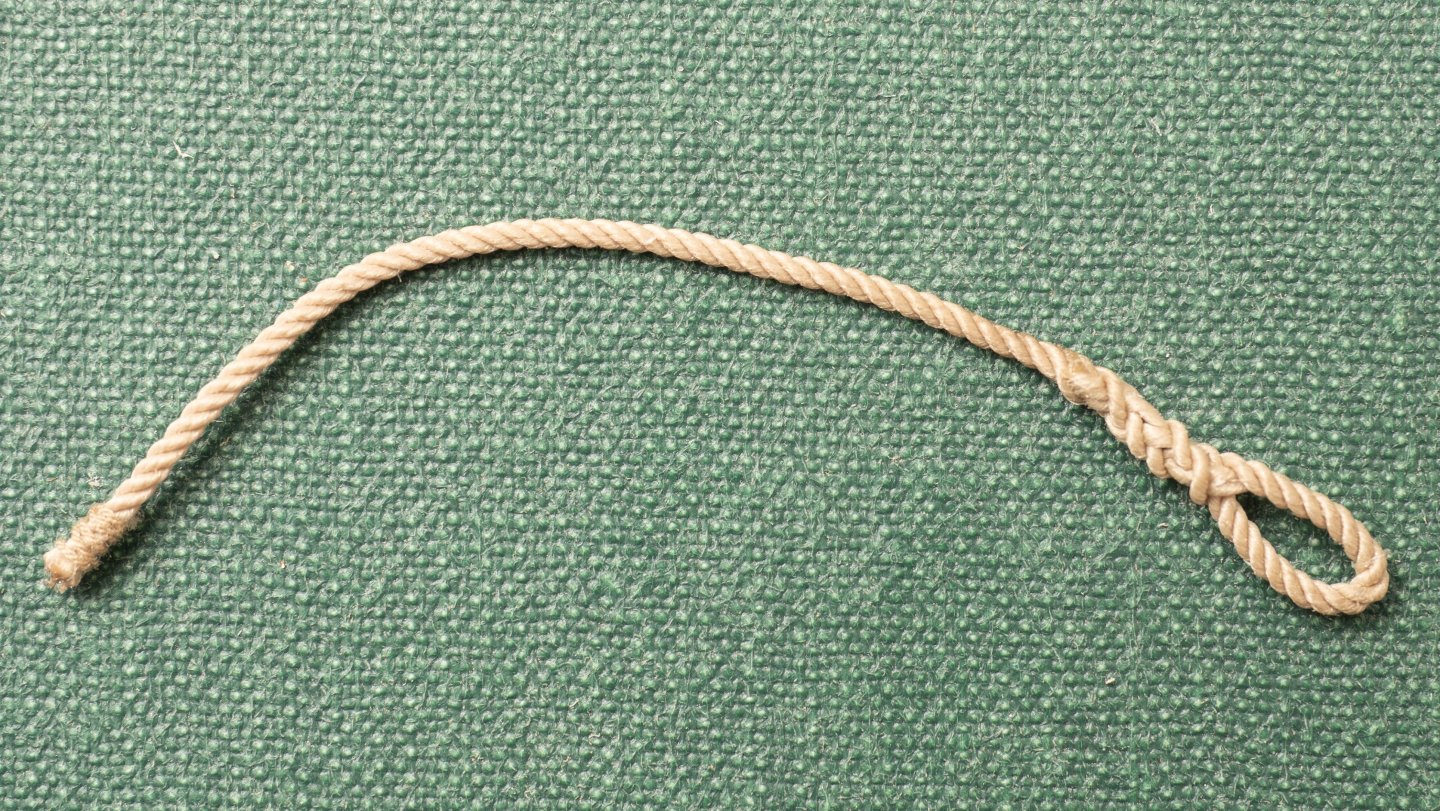
 Preparing to put the lashings on the main yard. These are shown in drawing MSR 3 (Part reproduced below © Estate of John F. Coates, reproduced with permission): Not quite sure how these lashings were secured on Olympias. Tried a couple of approaches using 0.5mm polyester rope (from Ropes of Scale - on the actual yard I will use 0.35mm rope as closer to 8mm rope at 1:24) on a piece of dowel (see image below). The sequence is of a "common whipping". In the second image the loop has been pulled so that the end on the left is pulled under the lashing coils and then the ends trimmed off. The whole thing was then coated with polyurethane varnish to hold it in all together and in place on the dowell. Ive also tried a "round lashing" (on the left of the third image),with a clove hitch securing both ends of the lashing. The "round lashing" is often quoted as being suitable for securing two poles together, but leaves the rope ends exposed and liable to get caught up with sails etc in use. I think the "common whipping" looks neater (despite the bulge under the coils where the ends are pulled in) but neither arrangement feels that secure to me given the loads, and handling, that the yard would be subjected to in service...
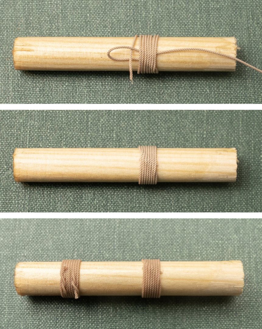

-
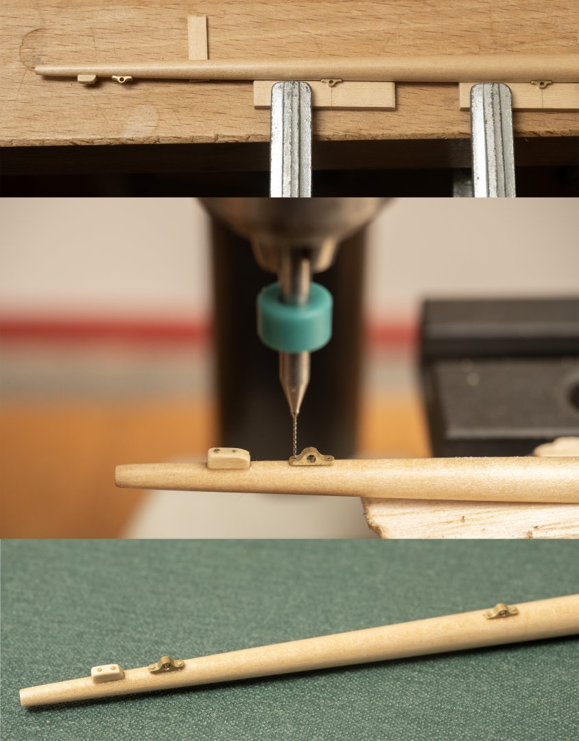
Fixing the brail fairleads to the boat yard. Drawing MSR 8 shows copper "tingles" fitted underneath these to protect the spar from wear. However, phtographs of Olympias show these were not fitted and so I have left them off. The farileads were first fixed with epoxy and then drilled through into the spar before fixing with 0.3mm brass nails. I found it quite challenging to align the tiny (0.35mm) drill with teh holes in the fairleads and broke 2 in the process of drilling the 12 holes in the boat yard. With hindsight it would probably have been easier to drill the hole through the brass fitting and into the yard in one go...
- 319 replies
-
- 11
-

-

-
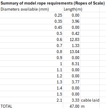
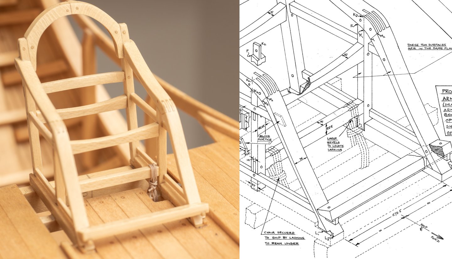
Ive ordered (and now recieved) ropes made by Ben of Ropes of Scale for this project. Ive gone for polyester tan as a reasonable match for the mixture of Hemp and Polyester rope used on Olympias. I constructed a simple spreadsheet to convert the rigging list (defined in drawing MSR 10) into 1:24 scale and then match against the diameters offered by Ben: the spreadhseet then sumarises the totals of each rope diameter for ordering: So 47 m in total. As Ben makes these up in 6m lenths I have some margin (varies from size to size...). Whether this is sufficient remains to be seen. First attempt on the model today, lashing the Trierarch's chair to a quarterdeck beam (Image includes part of drawing MSR 26 © Estate of John F. Coates, reproduced with permission). Its very fiddly work, and Im still getting up to speed with it! In this case I was using Bens 0.35mm rope (equivelent to 8mm full size). I practiced with some sewing thread to work out a suitable method and work out how much rope I needed. When it came to using the polyester rope I whiped one end with Gutterman 120 thread, again very fiddly work. Ive yet to come up with a method for making this go more smoothly...Process then: 1. Start with a clove hitch around both seat and deck beams. 2. pass one more turn around both beams (to match the 3 overall turns shown in the drawing) 3. 3 half hitch turns around the lashing (again to match up with the drawing) 4. I couldnt get in there to whip the final end...so sealed with a drop of CA glue and then cut off. I ended up using a piece of rope 50mm longer than ended up in the lashing (to give me something to hold onto to do the half hitches at the end...) which means a 25% wastage rate for this first effort... Hopefully Ill get better as I go along...
- 319 replies
-
- 11
-
-
-
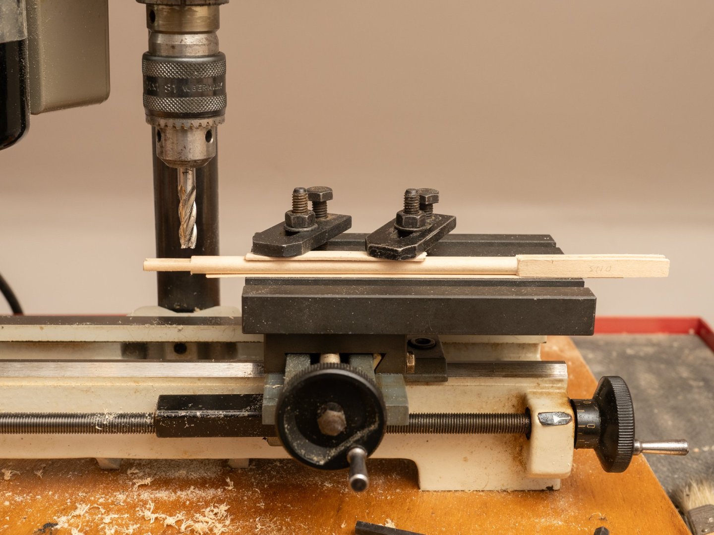
More rigging fittings. Brail fairleads this time. Small (105mm long full size , 4.35 mm at 1:24) bronze fittings defined in drawing MSR 8. Even working at this large scale, I do get to make some small stuff! They sit on top of both yards and I need 16 of them altogether. I made them on my Unimat in strips of 7 which was the most I could do given the extent of the transverse travel on the milling table...Used my "manual CNC" approach again. Quite a challenge to remember where I was in the sequence right through 7 repeats. I lost one strip because I didnt believe the dial movements ant tried to measure with my vernier guage...Turned out the dial settings were right and the measurement I made wrong...The mounting holes are 0.35mm in diameter and nicely fit some 0.3mm diameter (4mm long) brass pins that I just recieved from Dry-dock Models and Parts.

-
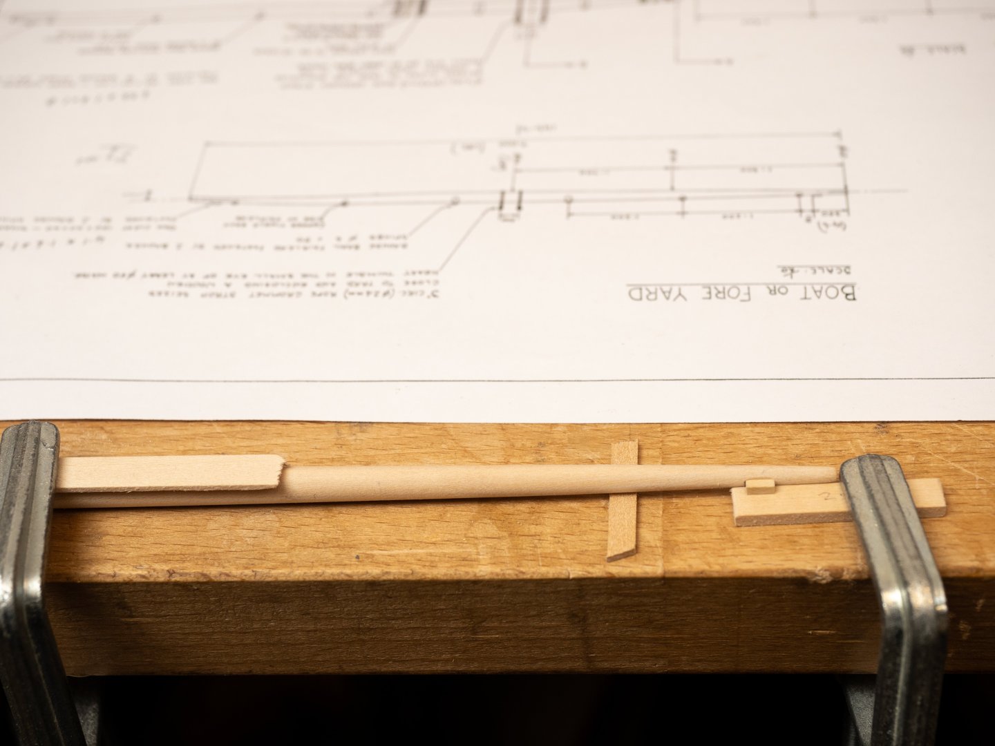
Thanks, Thukydides. I looked through Steel a few days ago, and missed that bit... Today Ive been fitting the brace cleats to the Fore Yard. A bit of careful positioning of the yard and a spacer to make sure they both end up on the same centerline (Image ncludes part of drawing MSR 3 © Estate of John F. Coates, reproduced with permission)...
-
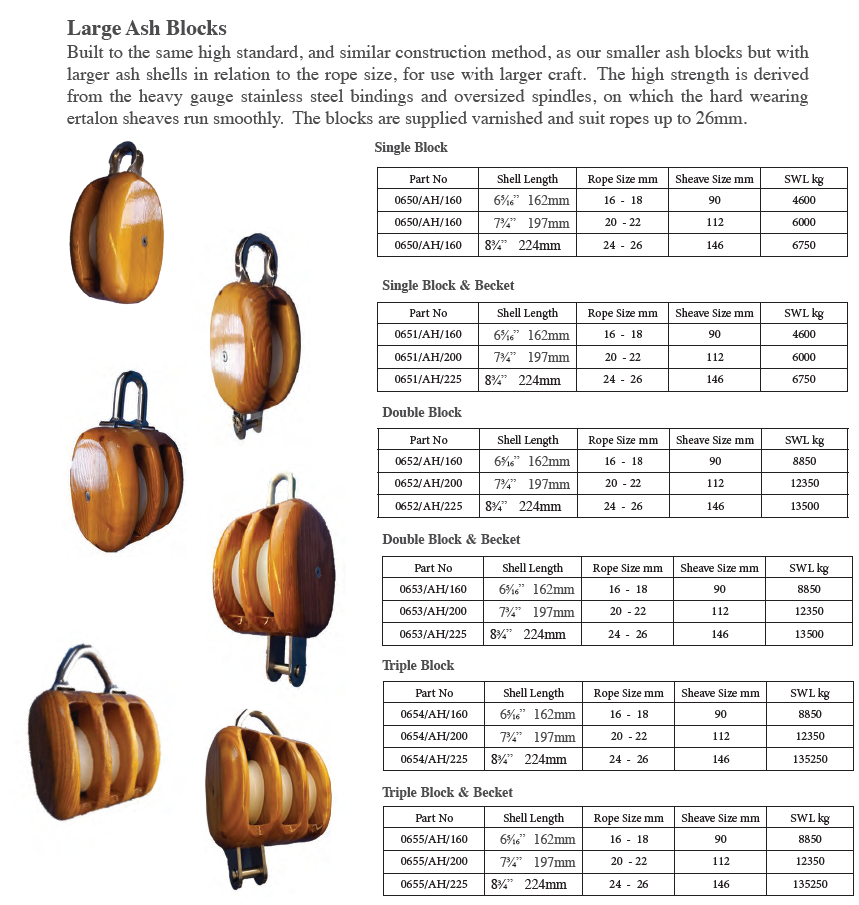
Im looking into making all the rigging fittings I need, blocks, deadeyes, fairleads etc. This page from Davey and Co's catalogue (Products – Davey & Co London Ltd) looks like a good indicator for appropriate block sizes for different rope sizes: I can also scale from photographs of Olympias, e.g. : I havent done any rigging for a very long time... Are there other good sources on block, deadeye etc proportions?

-
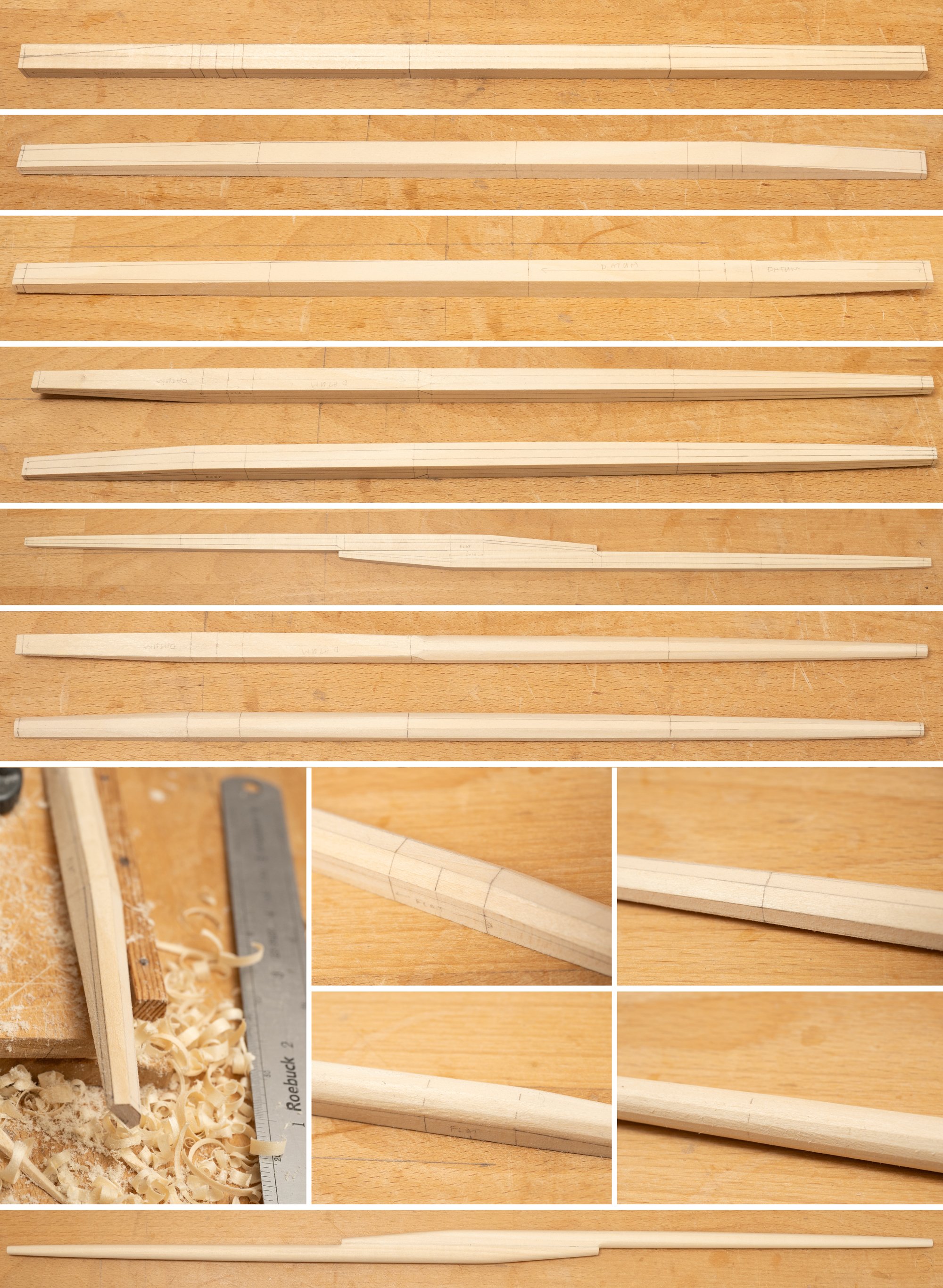
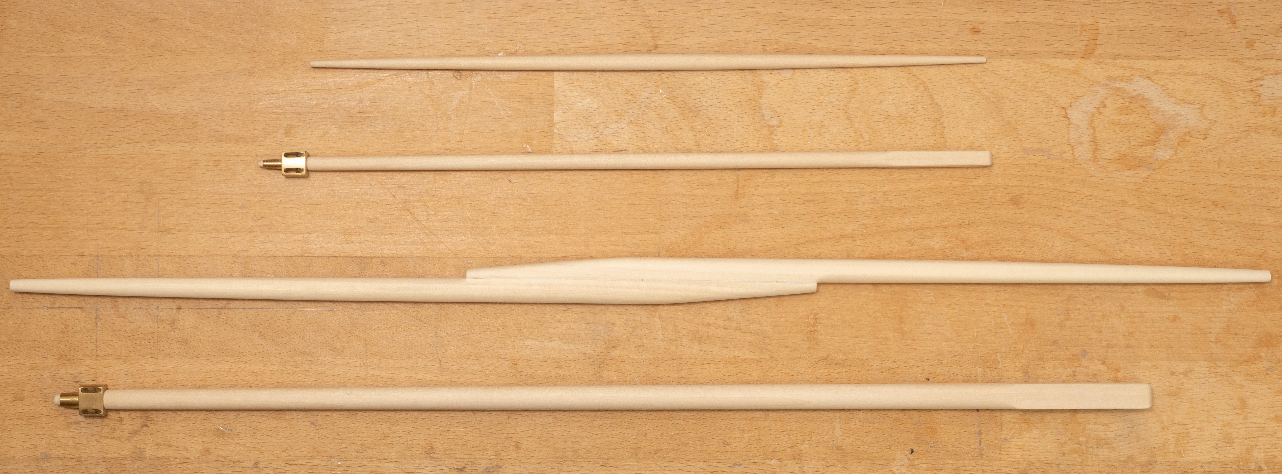
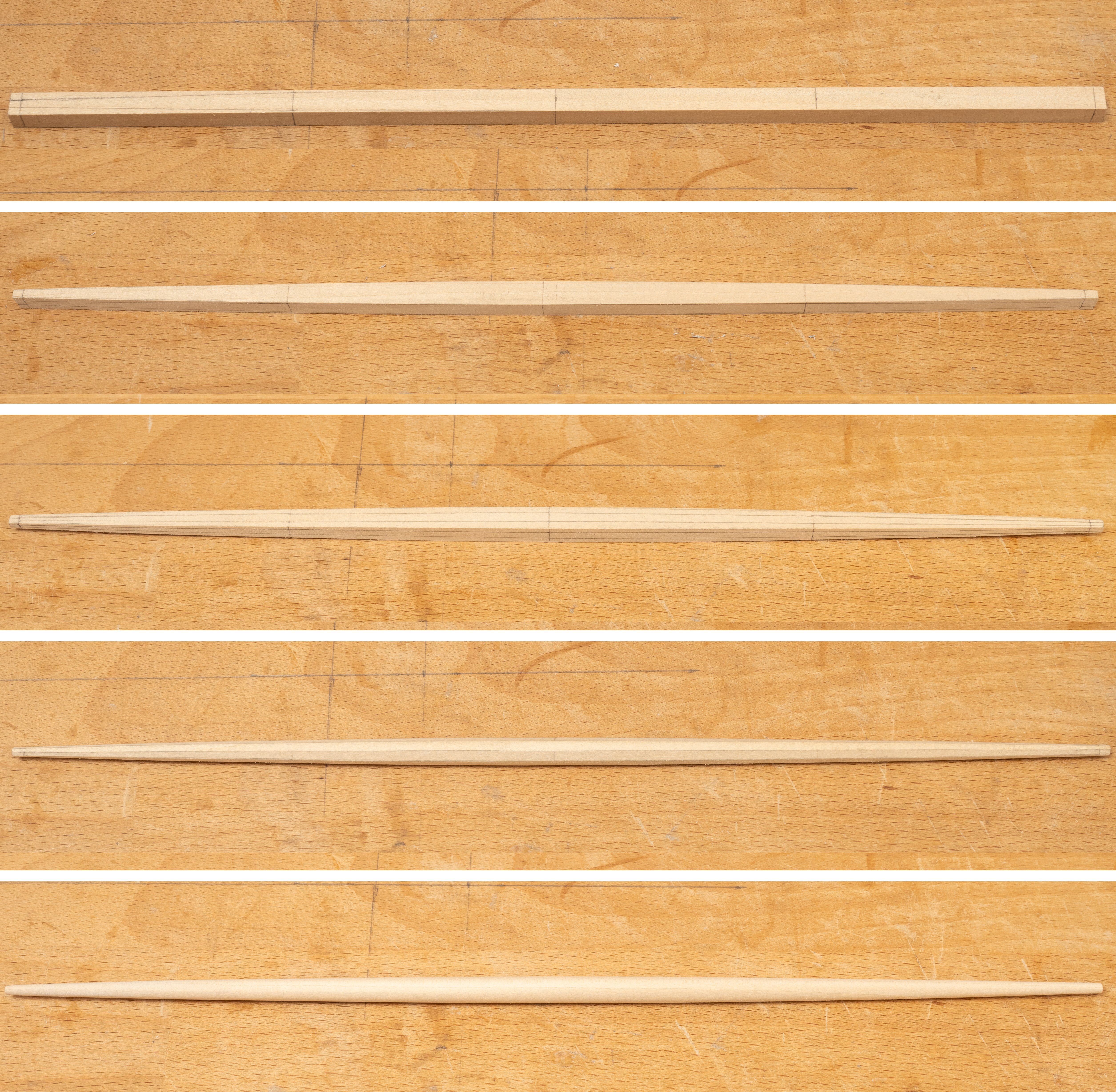
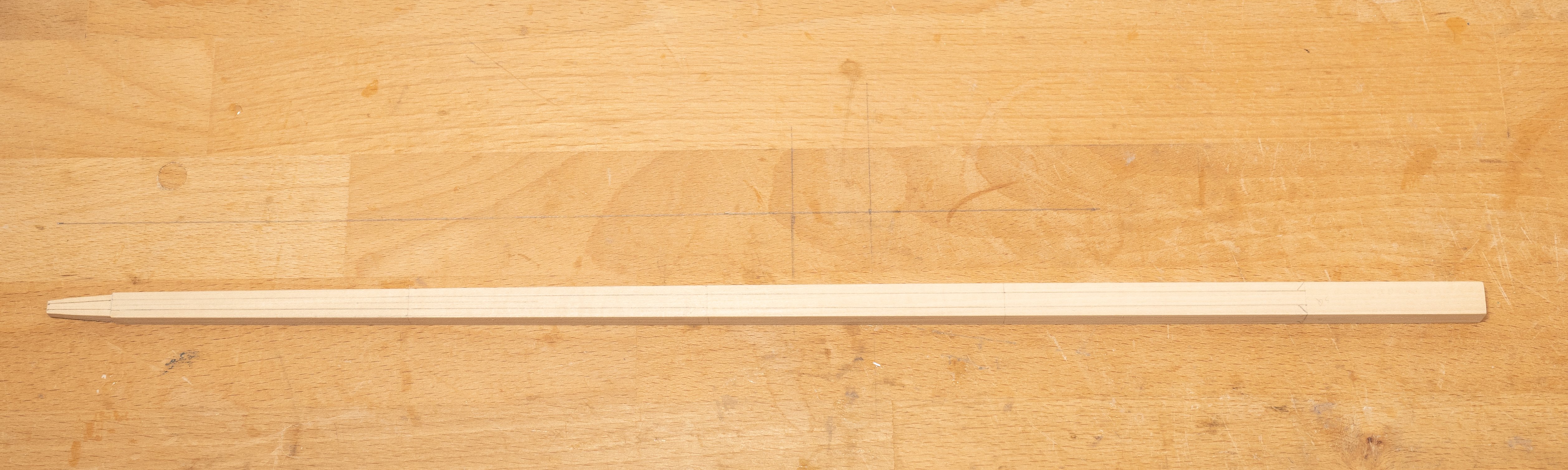
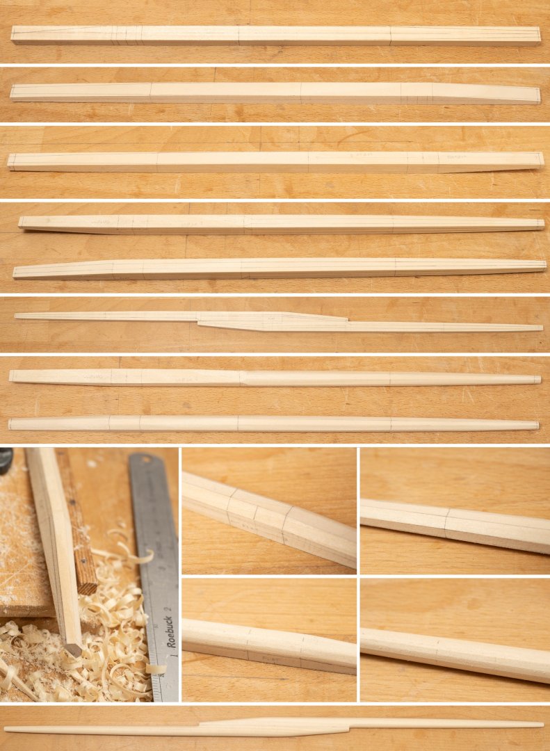
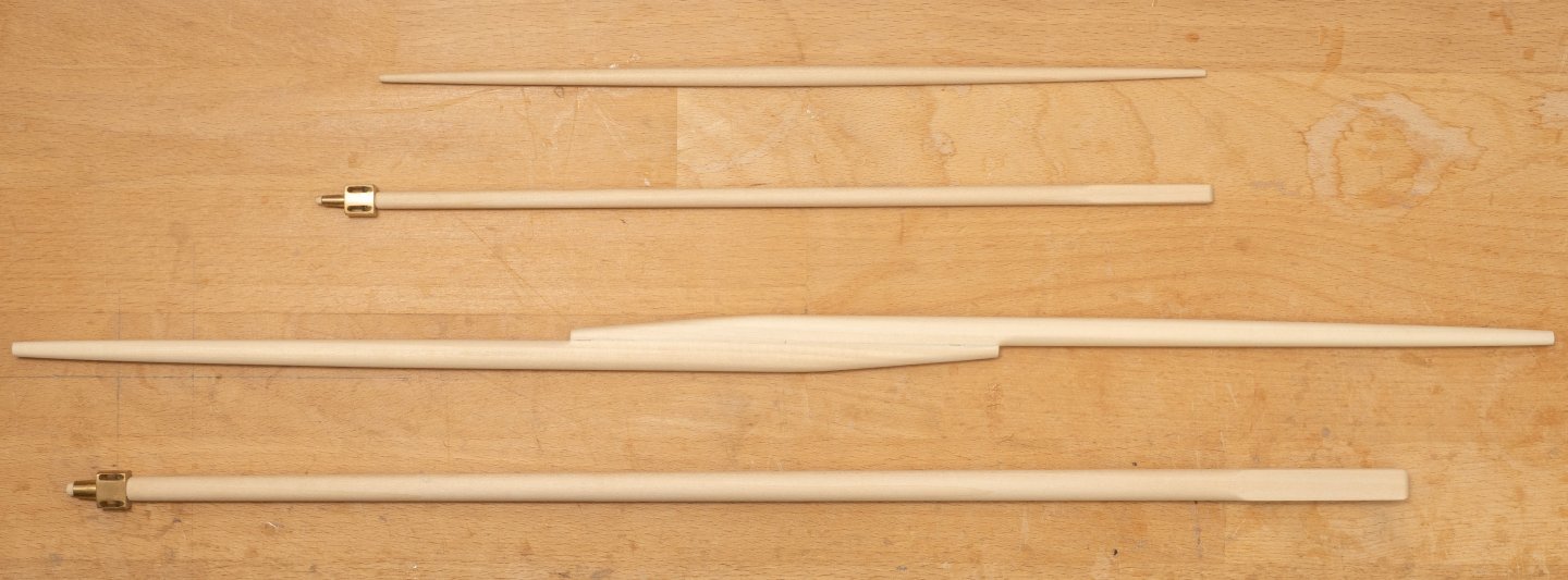
Shaping of the mainyard, took a bit more thought. Made of two pieces lashed together (like the illustrations in Roberts papers described above), with a relatively more complex transition of section where the two pieces are joined. I havent made yards for a very long time, but I remembered (for this last one at least...) to remark the circumference of the yard at the measurement stations at the point when it is octagonal to act as a guide to help make the faces even when shaving down the vertices to make the yard 16 sided prior to sanding to its final round shape... Finally a pic of both masts and both yards together, from which it is clear how heavily built the main yard was...
-
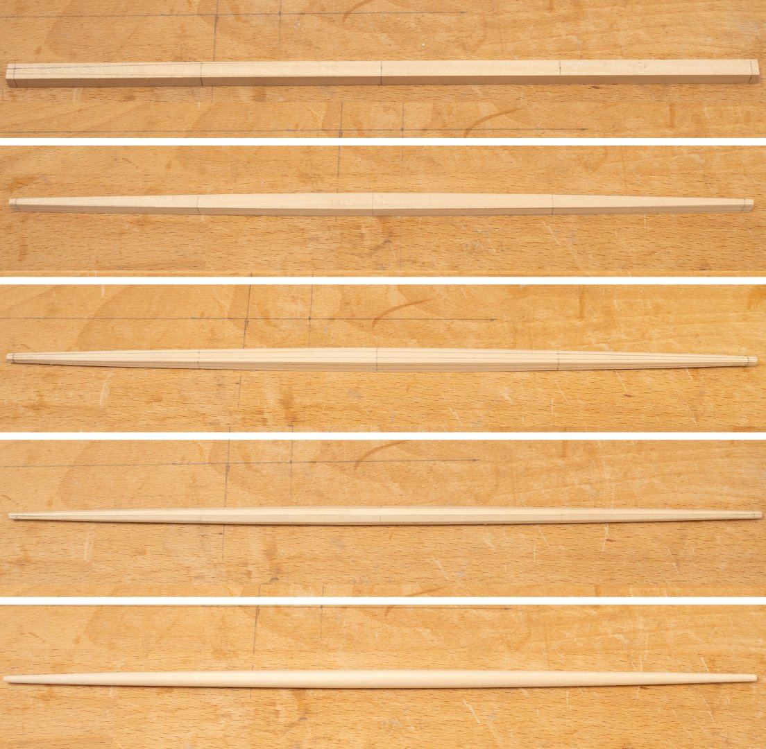
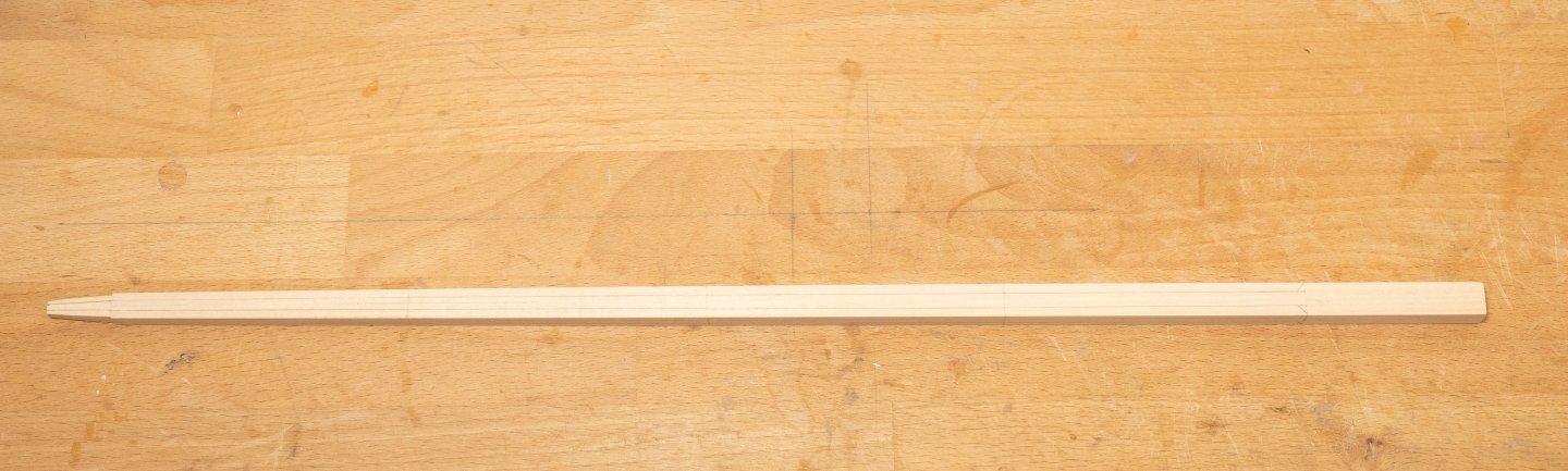
Completed the yard for the forward mast ("boatyard"). A nice , straightforward, tapered yard 7m long with a maximum diameter of 166mm (full size). Drawing MSR 3 gives diameters at the marked points in the series of photos below to help with the shaping:
-
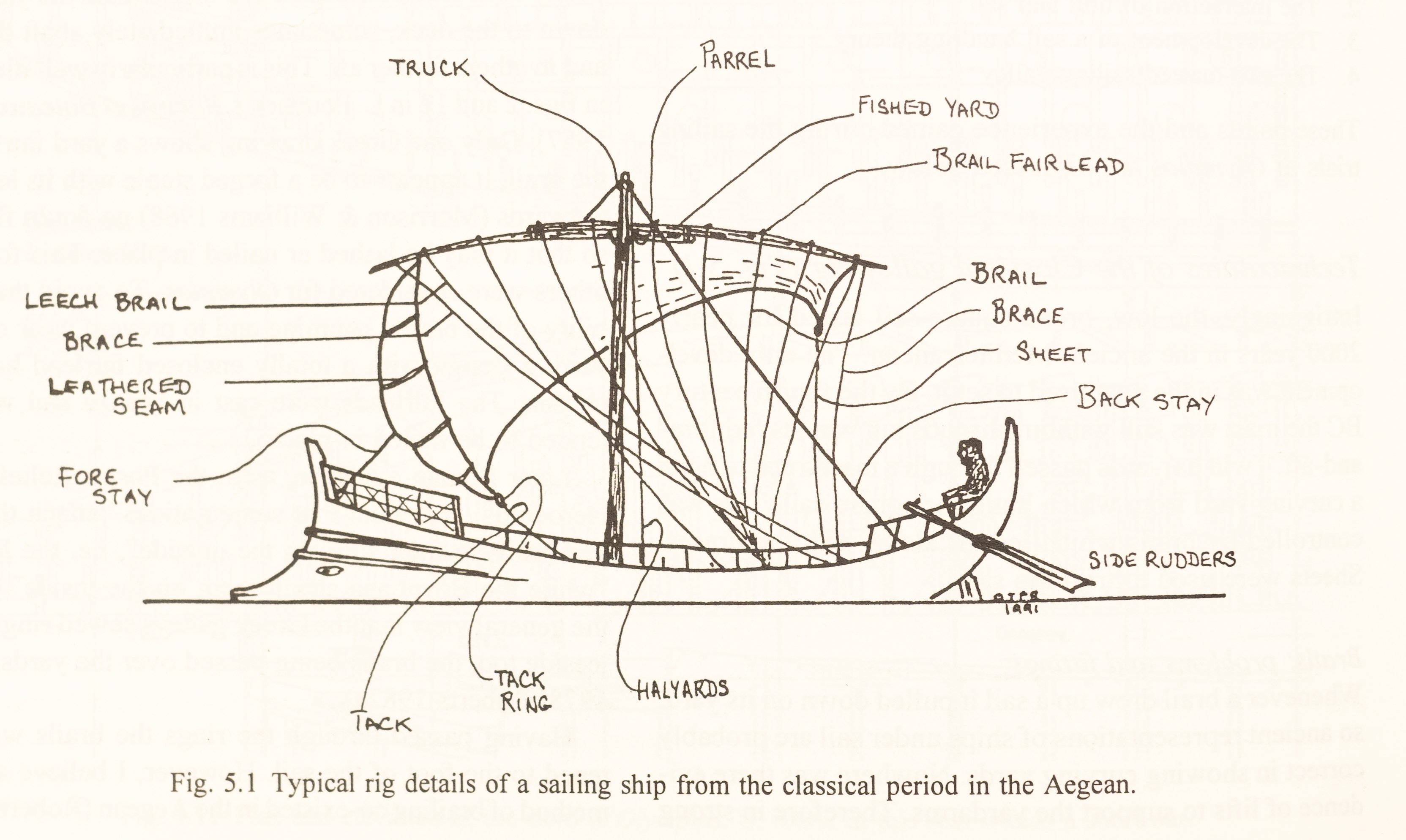
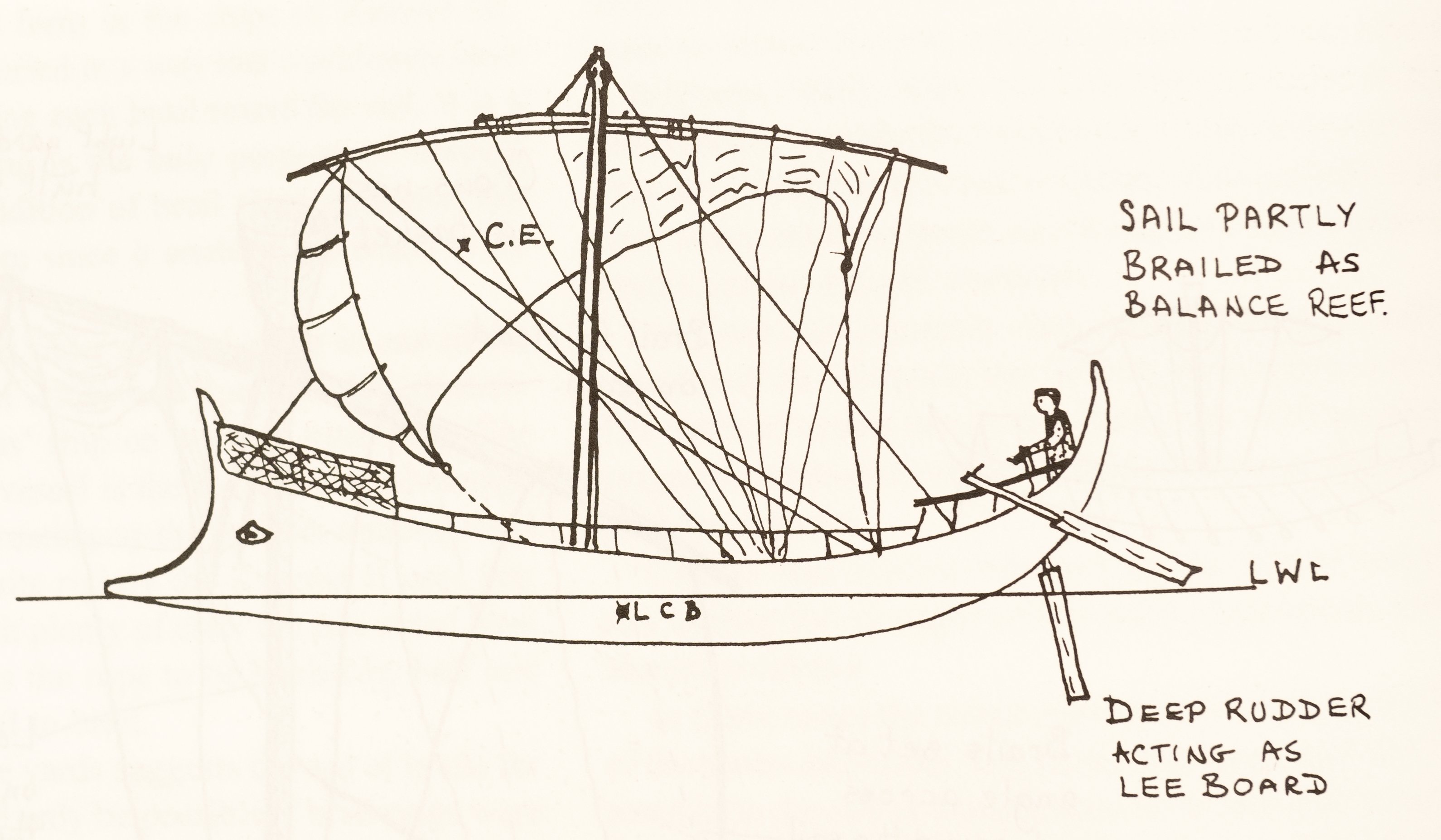
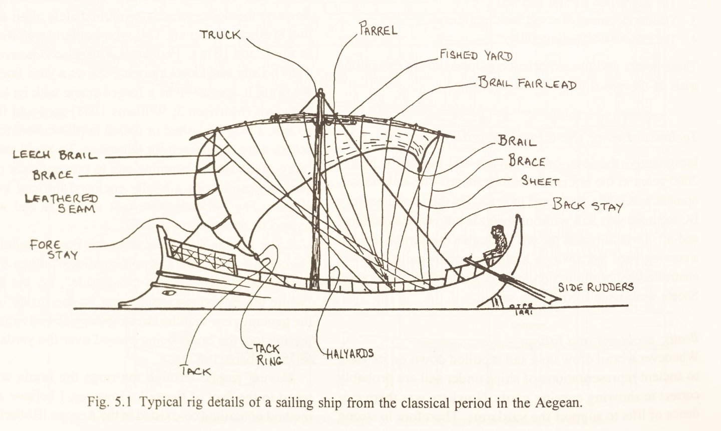
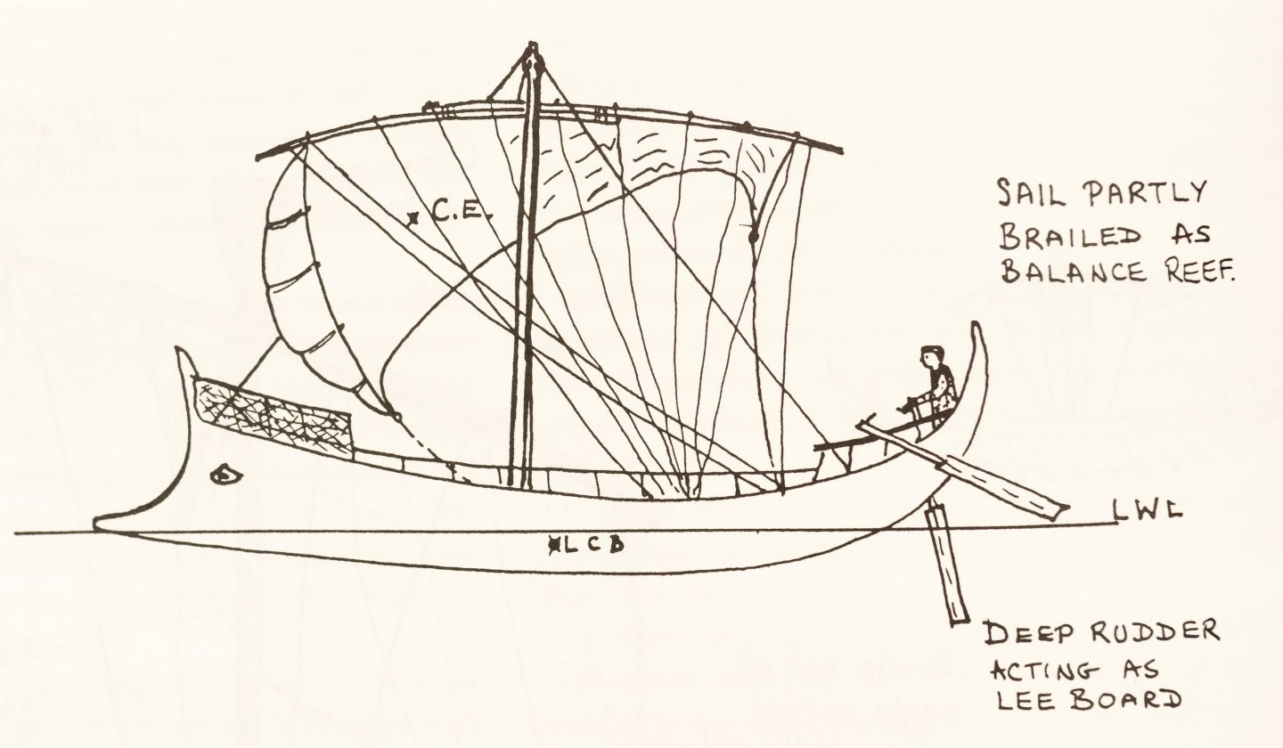
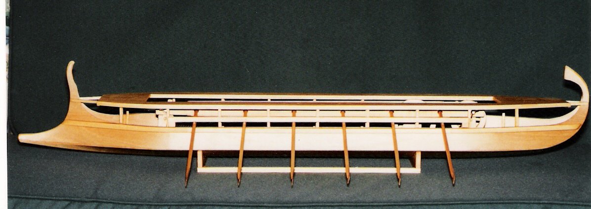
A short digression on the rig of Olympias... There were a number of collaborators in the design and construction of Olympias andO.T.P Roberts was resonsible for the design of the rig (I have two articles by him describing the design and subsequent sailing trials, published in, The Trireme Project, Operational Experience 1987-90 Lessons Learnt and The Trireme Trials 1988, both published by Oxbow books). The rig design featured a large and a small sail and a large and small yard as described in Naval Inventories at the time, although there is apparently no iconographic evidence for a two masted rig in galleys of the last millenium BC. Morrison and Williams (Greek Oared Warships 900-322BC, Cambridge 1968) poi9nt to evidence that the the main mast was unrigged for battle and the smaller "boat sail" was retained to be used for down wind escape if necessary. The forward mast on Olympias also serves as a useful gantry to raise the much heavier main mast (method described in drawing MSR 13) The sails on Olympias were rigged on a yard hoisted by twin halyards but is unsupported by lifts. As mentioned before the mast is only supported by fore and backstays and has no shrouds (as designed) requiring a substantial tabernacle. The sail is controlled by brails and the downward pressure of these (and the yard braces) is thought to account for the downward curving yards seen in the icongraphy. An illustration of this , for a one masted galley is shown below.(figure taken from The Sailing Rig of Olympias, p30, The Trireme Project, Oxbow Monograph 31) There are no reef points, as such on the sails. Sail reduction, and furling, is accomplished by brails passing through rings on the leeward side of the sails, and fixed to the foot of the sail. Fore and aft balancing of the rig could be achieved by partly brailing the sail to move the center of effort fore and aft to counter weather or lee helm as required, as shown below (figure also taken from Roberts article in The Trireme Project.) Trials on Olympias also showed that slightly drawing up the middle brails when sailing downwind. Apparently this helps maintain the rectangular shape of the sail, preventing the clews pulling in and spilling the wind out of the bottom of the sail. In the two masted configuration this also helps the airflow over the forward boat sail. Performance on trial suggested that progress could be made to windward with close reaching up to 60 degrees off the wind while making 7 degrees of leeway. In light weather a sailing speed of 2.5 kts could be doubled by light rowing as a bireme (i.e. two top rows of oars only) which would have enabled 1/3 of the crew to rest on passage, even in light winds. Roberts comments that the main yard on the reconstruction was over engineered and so did not flex in the way sugested by the above illustrations. It was also very heavy, so the original plan to make the halliards from 45mm diameter leather were amended to use 20mm 3 strand polyester rope for safety reasons...
-
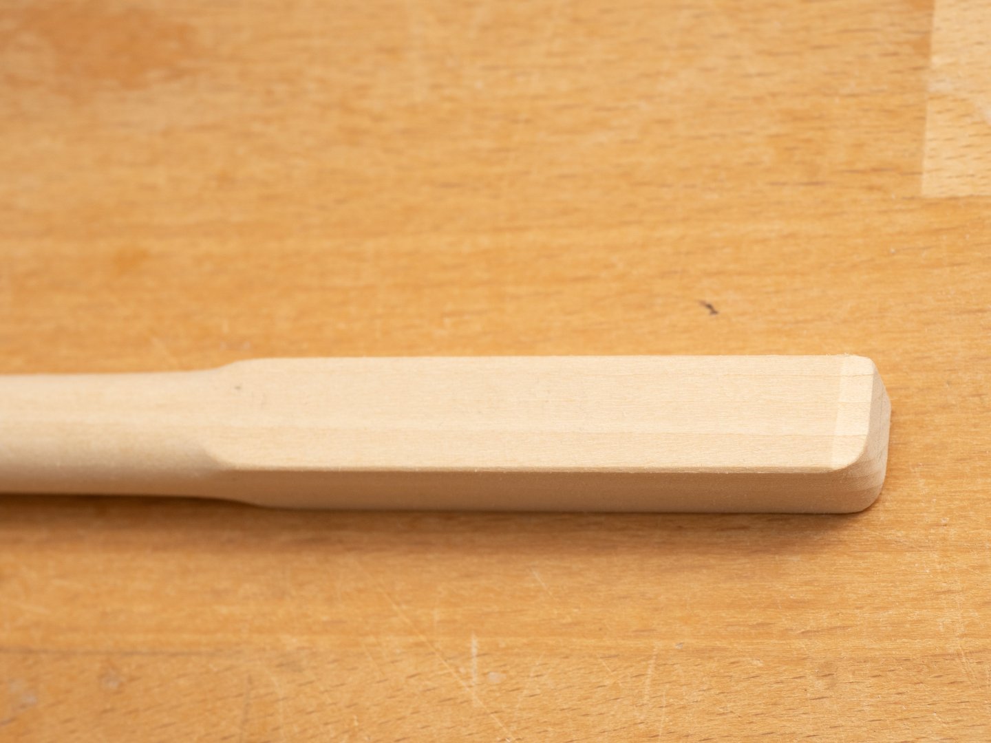
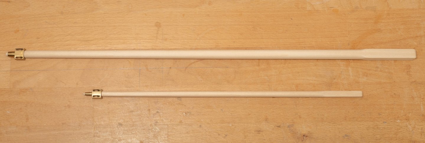
Ive chosen the same wood to build the spars (Lime) as used for the rest of the hull. Spruce might have been nice but I always think the grain looks abit to big at this scale. Her is the Main mast tapered and marked out for "octagonalizing": The base of the mast is square where it fits into the tabernakle and the top is tapered to fit the mast head fitting described earlier. The square base is finished with a radius at the forward edge to make raising and lowering the mast easier: Finally, both masts with their masthead fittings:
-
More experimenting with rope... Ive never been much good at eye splices, so I had a refresher session with some full size rope (polyester 20mm diameter) and then tried with some of "Ropes of Scales" 1mm polyester. I got a few of my tucks out of sequence but it seems to be feasible at this scale (if a little fiddly..) - I just need some more practice!
-
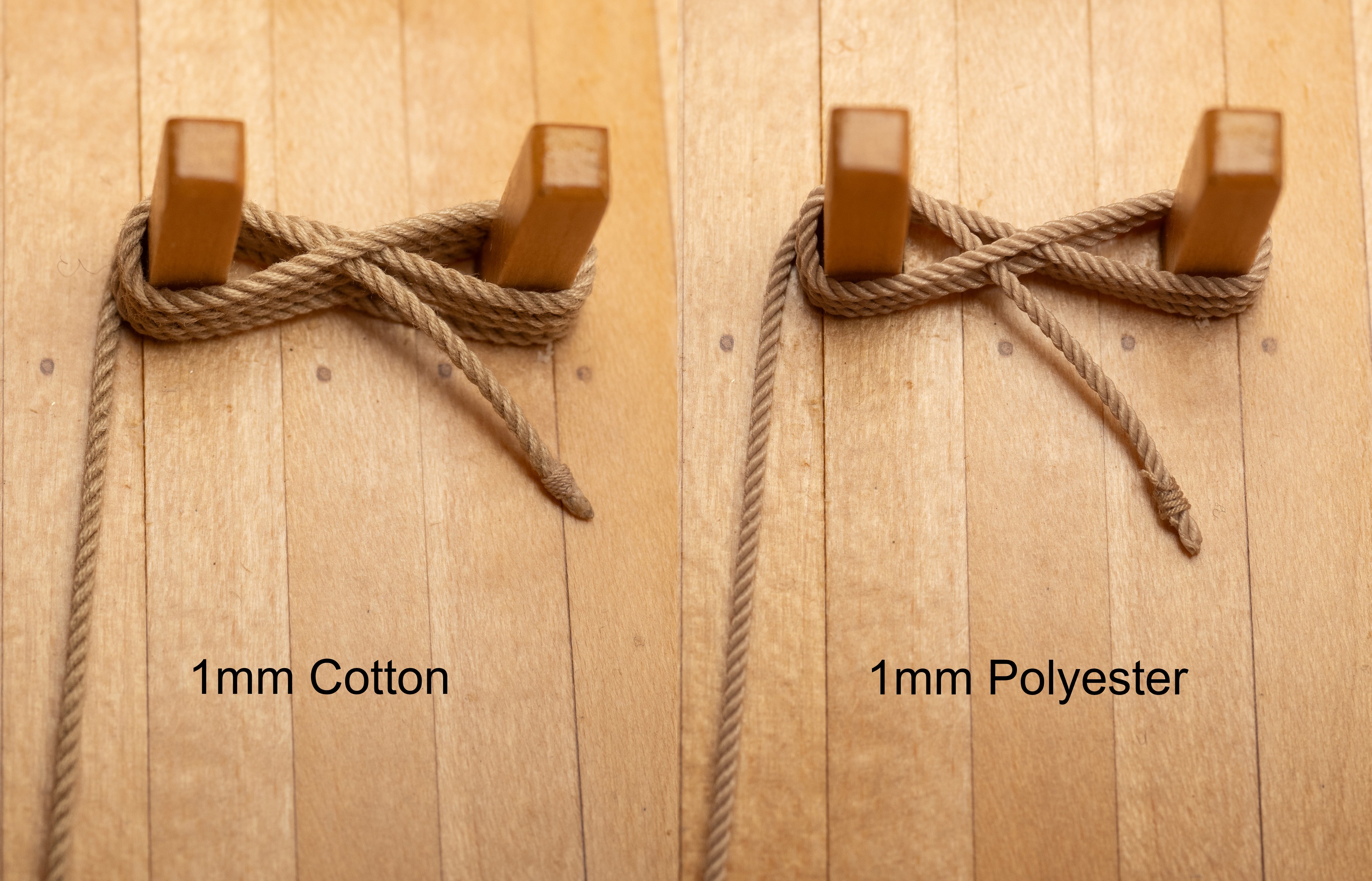
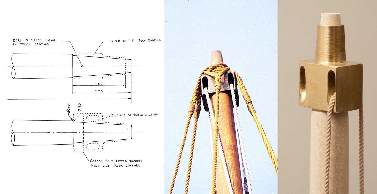
Ben from Ropes of Scale was kind enough to send me some samples of his excellent polyester and cotton ropes to help me decide on a way ahead for the rigging. Here is a picture of his 1mm polyester rope passing through the main masthead casting alongside an extract of drawing MSR 7 by Owain Roberts ( © Estate of John F. Coates, reproduced with permission) and a photograph of the full size ship. the polyester runs satisfyingly freely over my machined fairlead radii, which is nice... The photo of the full size ship shows shrouds in addition to the fore and backstays specified in the design by Owain (see discussion above). Interestingly while hemp was specified for the shrouds and stays, polyester rope was specified for the main yard lifts for safety reasons... The next image shows images of Bens polyester rope and cotton rope made off onto the main bits. I have some more experiments to do with sp;icing, rope coils etc. but I think I'm inclining towards polyester rope (although the slightly "furry" cotton, at 1:24 scale, looks quite like the full size hemp on Olympias in a lot of images...). Im also quite keen not to provide too much food for moths etc on my boat...

-
Interestingly I went to a talk, in Dartmouth, last week by a man who has been building lovely models of atmospheric steam engines since the 1970's (Home - David Hulse Steam Engines). The top of the boiler of one of his engines is made of lead and it has been in a sealed case together with Japanese Oak for 50 years. He says he has seen no deterioration at all...
-
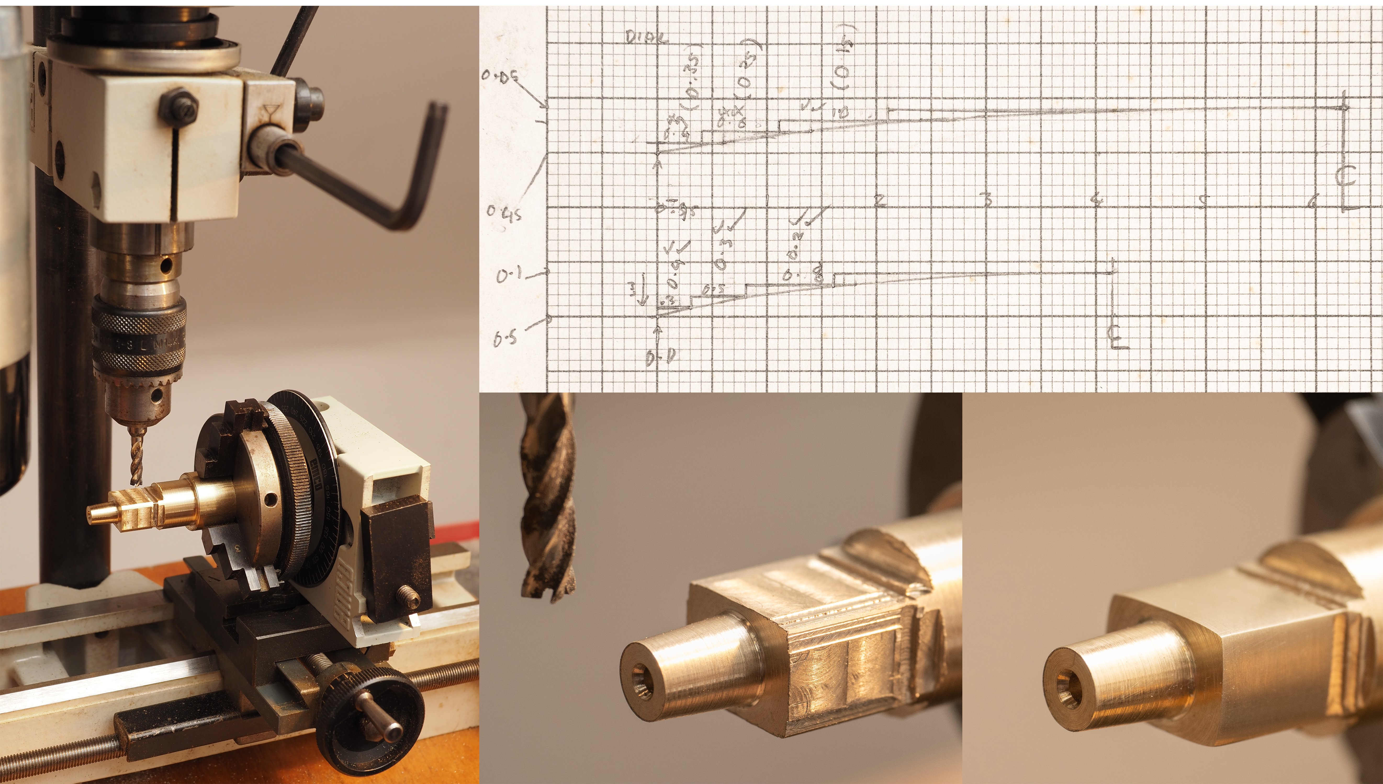
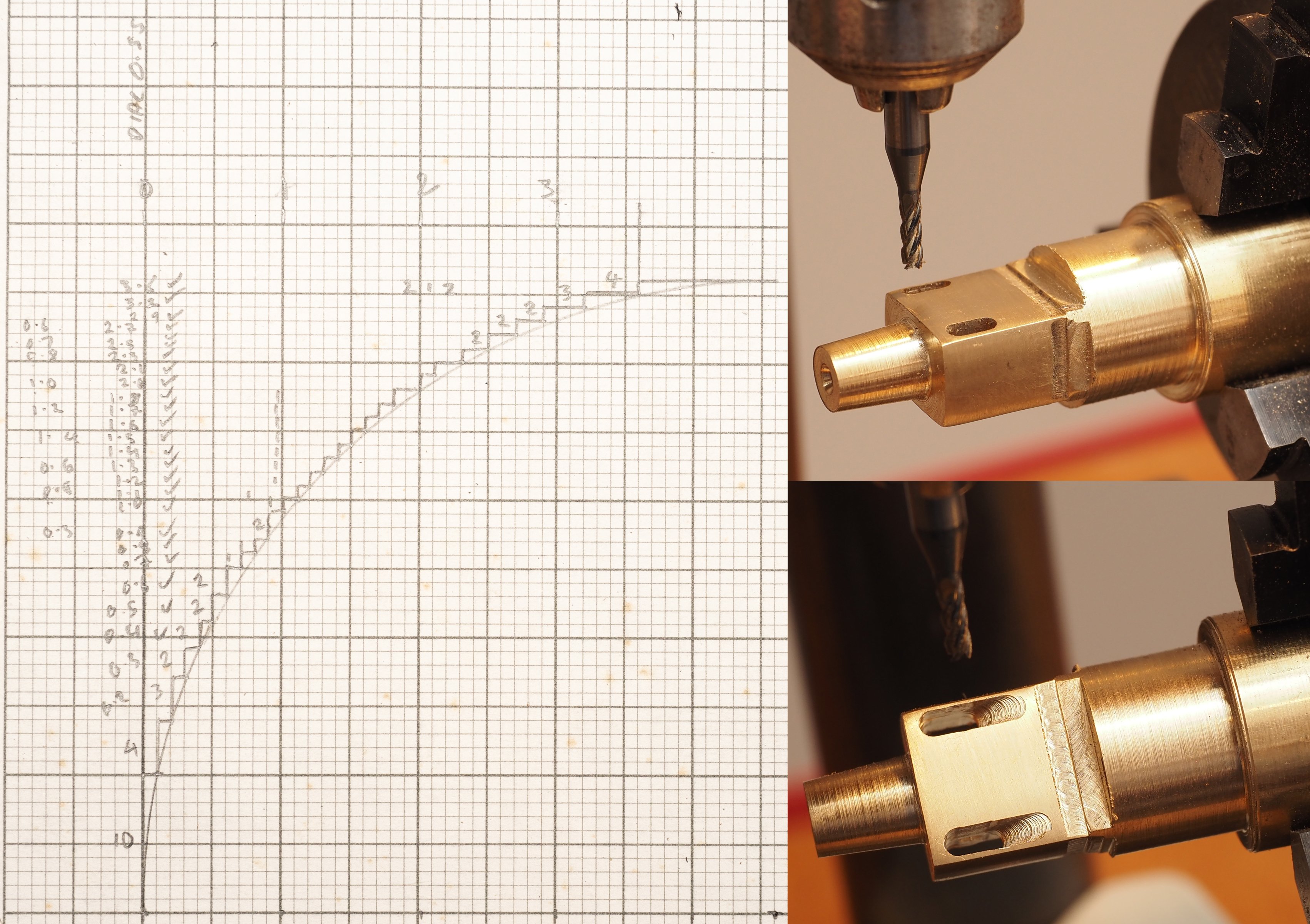
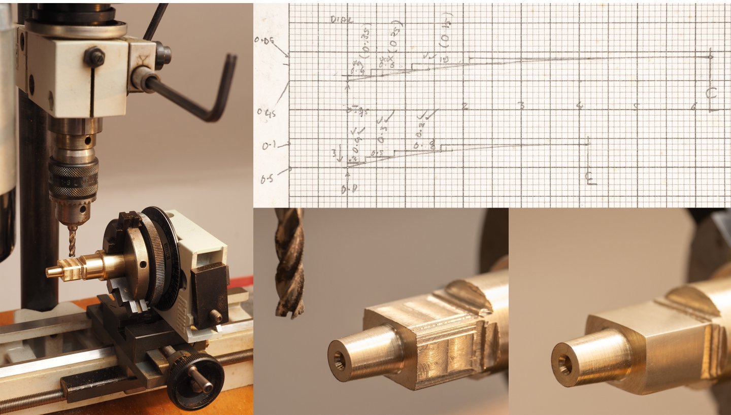
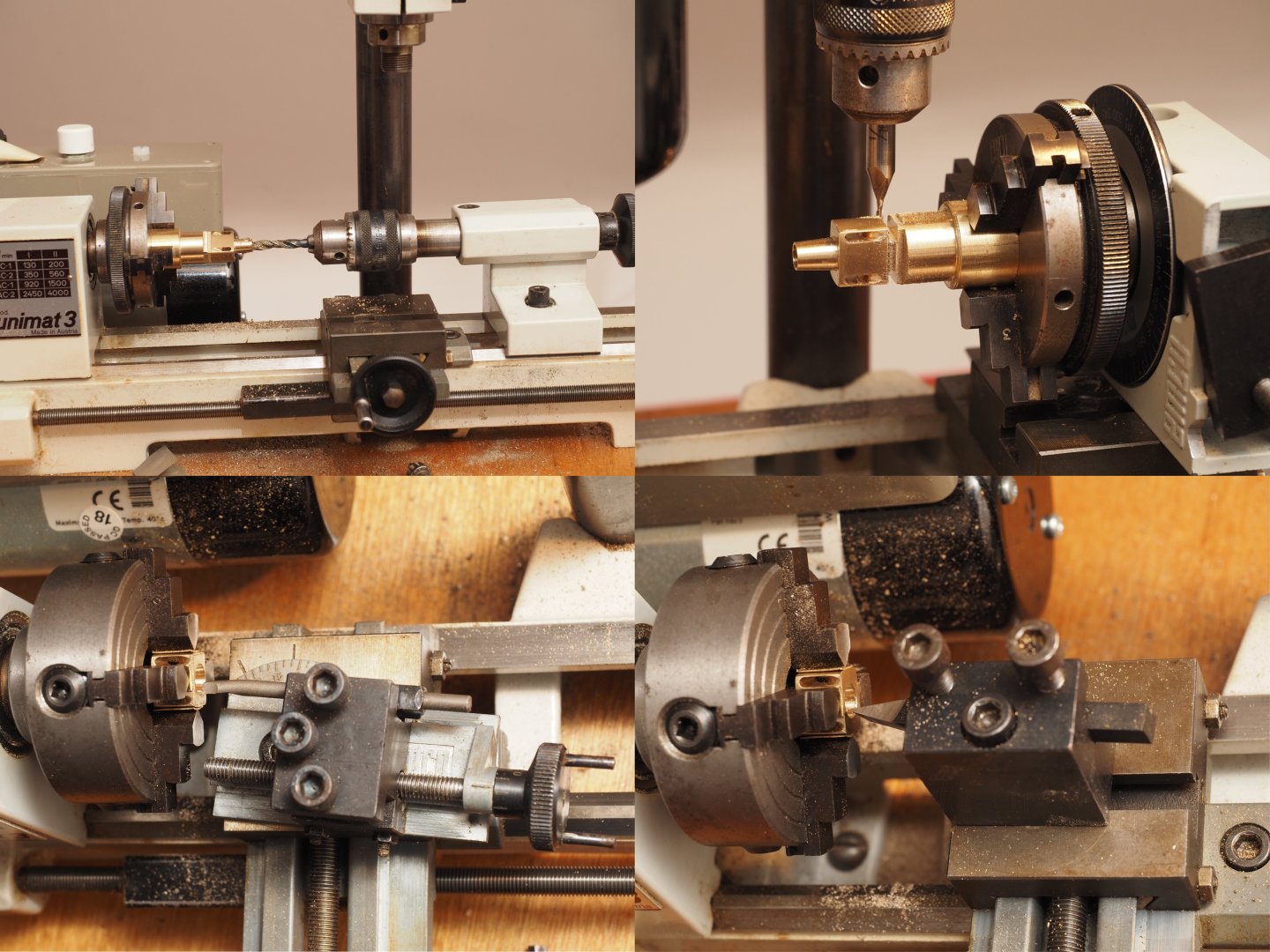
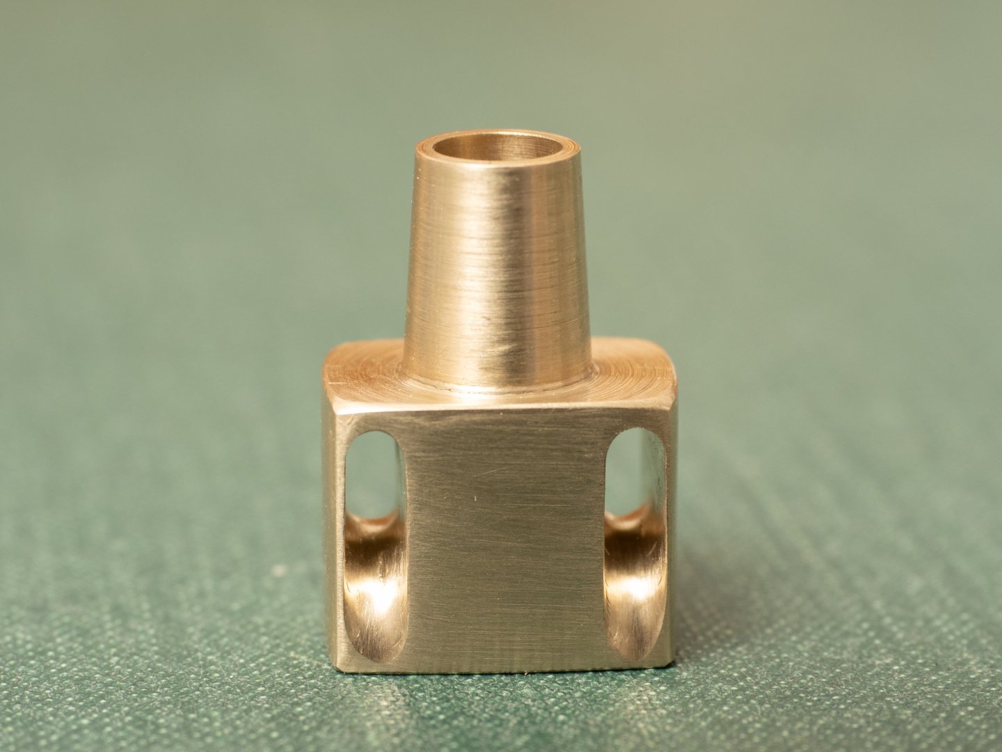
Some images of the remainder of the machining operations for the main mast truck. The graph paper images illustrate a method I have for machining complex shapes manually turning the feed dials as a sort of poor mans CAM! Requires quite a bit of concentration to make sure I am turning the right dial the right way and in the right sequence! Particularly for the radii inside the halyard fairleads where I couldn’t see what is going on. After machining all the “steps” it’s a case of using files and sandpaper to smooth out the surface…

-
Another source that may be of interest: The Naval Architecture and Oar Systems of Ancient Galleys, J Coates, Chapter 9, The Age of the Galley, Conway Maritime Press 1995. Contains J Coates interpretions and drawings of Helenic Pentaconters, Biremes, Trirmens, as well as later Roman Galleys (Liburnians, Fours, Sixes etc.), as well as a good summary discussion of the design drivers explored by the Trireme Project. There is a particularly useful general arrangement and lines plan of a Roman Liburnian based on the Lindos relief and the ships on Trajan's column, which could be a good source for a simpler galley model, ("only" 50 oars, 20m long...). I think it was prepared for a planned full size reconstruction at some time and would make a really nice model... If anyone is interested it would be worth contacting the Trireme Trust archivist to see what else is available for this reconstruction.
-
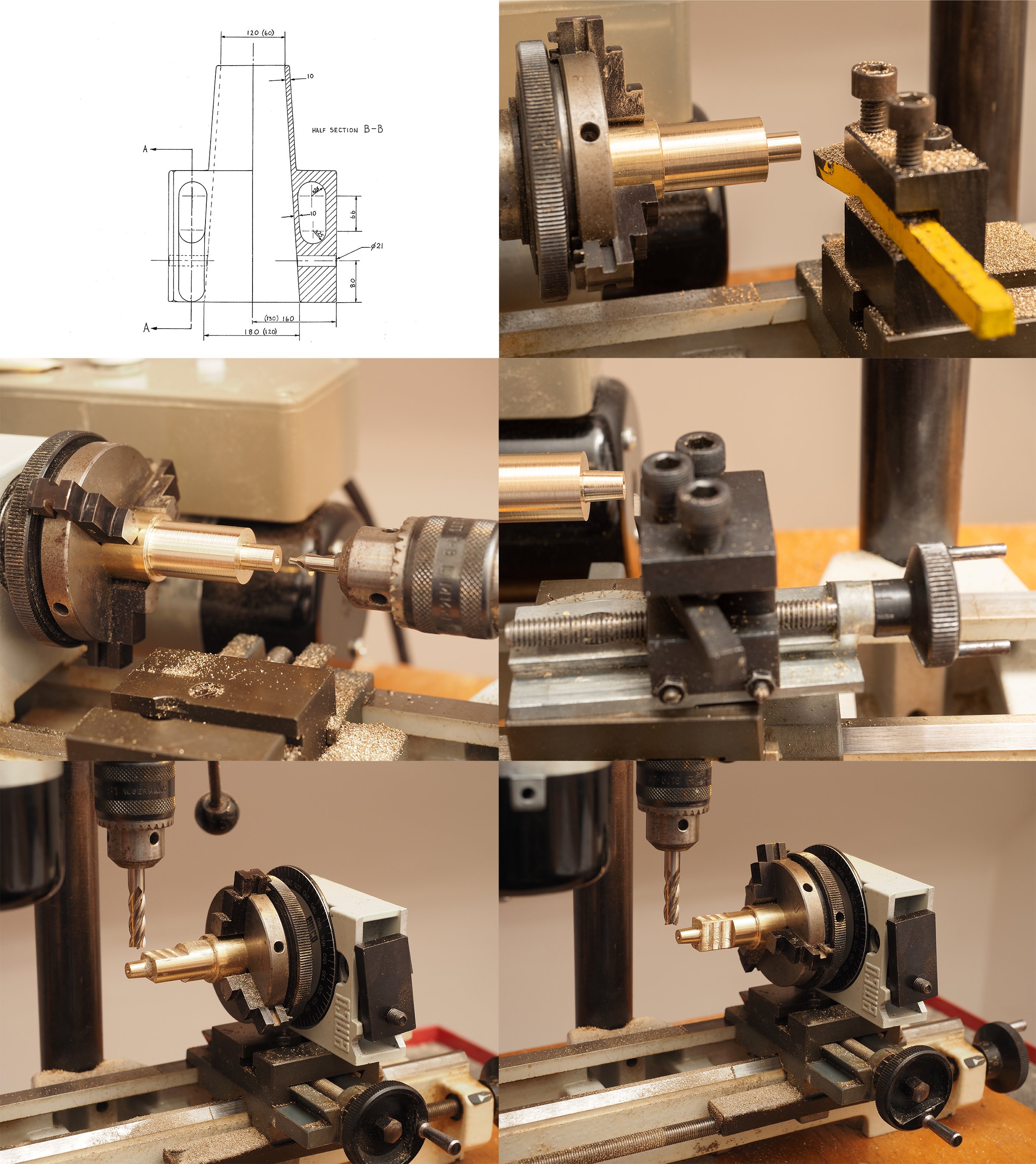
Now turning my attention to the rig, I made the decision to model the rig as designed by Roberts (Ref The sailing Rig of Olympias, O.T.P. Roberts, The Trireme Project, Oxbow Monograph 31, Oxbow books 1993) rather than reflect the changes made to the rig during build and subsequent sailing trials. The most significant difference involves the shrouds. Roberts states that the masts of Mediterranean vessels of this type and period were without shrouds and merely stayed fore and aft (hence the substantial tabernacles fitted – see above). Pictures of Olympias, however, clearly show shrouds fitted but Roberts states that these were fitted because “Captain Dimitris Papadas…..took fright when seeing the tabernacles into which the masts were to be stepped and insisted that shrouds be fitted”. “Unfortunately, he fitted shrouds as in a fore and aft rig which made it impossible to brace round a reefed square sail”. As an aside, it is worth getting hold of these references on the Trireme Project (Olympias) for anyone interested in ships of this period and type. There were lots of papers presented by a lot of collaborators documenting the design and the trials, with a huge amount of information and discussion about all aspects of design and operation. I can give you a list of what I have (and what Ive found useful) , or you can contact the Trireme Trust archivist at Wolfson College. So, I’m going to model the rig as designed by Roberts, rather than as built (it is also a lot easier for me to omit shrouds into my disassembling design…). Roberts design for the rig is documented by drawings MSR 1-10. Starting with the masts drawing MSR 2 states that the head of the mast should be “tapered to fit the truck casting”, so it makes sense to make the truck casting before the mast… Twin Halyards pass through the mast truck to hoist the main yard. In Roberts design these trucks are bronze castings that include fairleads for these halyards and a shoulder above them to support the forestay and backstay. The castings for both main and foremast are defined by drawing MSR 7. I decided to machine these fittings from brass bar stock rather than cast them. It has been some time since I’ve done a significant metal machining project with my little Unimat Lathe, and this project enabled me to refresh myself with a wide range of its capabilities (including a first outing for the 4-jaw chuck that I just managed to get hold of on eBay!). The first steps are shown below (includes extract of Plan MSR 7 © Estate of John F. Coates, reproduced with permission):

-
I think the best approach is probably to turn using the oars. I would prefer to stop oars on the inside of the turn (either out of the water or in the water for more effect). The boat should definitely turn then as it will only have thrust from one side. Olympias (full size) achieved its tightest turns using a combination of rudders and rowing ahead on one side only, so using the oars to turn would be an authentic way to manoever . If your boat is directionally unstable you could help that by fitting a skeg at the back end. If there is any wind at all the situation will get confused as it will acto on the hull above the water to turn it one way or another - best to only use the model on a still day (or an indoor swimming pool!).
- 536 replies
-
- 3
-
-
- Quadrireme
- radio
- (and 1 more)
-
As for model rowing boats performance, you do have to modify your expectations based on the scale effects. Different aspects of the boats performance will scale differently. One critical aspect is that if you operate the vessel with an appropriate stroke rate (e.g. 45 strokes per minute) the maximum speed can never be more than the speed of the oar blades relative to the boat. This should actually look quite realistic (e.g. the model will travel at a speed roughly equal to full size speed multiplied by the scale factor), but the speed will be far to low for the hull to behave as full size (e.g. the bow wave and wake will be infinitesimal on the model) and too low for the rudders to act as they would on the full size boat. One way around this would be to increase the stroke rate massively (which would look ridiculous and also be difficult mechanically) to achieve a hydrodynamically scale speed for the hull (Froude Number) The other thing to watch out for is that wind effects scale massively for a small model. A very light wind is the equivalent to a full size gale and will stop the model dead. I made a very simply model of a rowing machine, prior to starting on my Olympias model. Only 12 oars operating in a simple circular path: I also produced a simple spreadheet to simulate the physics of the model and carried out some trials to validate the spreadheet with the model: Rowing Machine Calculation.pdf As you can see the model managed a speed of 91mm/sec at a stroke rate of 45spm. Quite slow and, but looked about right for the "scale". I also tried the model out crossing a reservoir on Dartmoor. I chose a day with no wind at all and it looked quite convincing as it made its way accross the lake...I didnt have any rudders, so i could only go in a straight line!
- 536 replies
-
- 5
-
-
- Quadrireme
- radio
- (and 1 more)
-
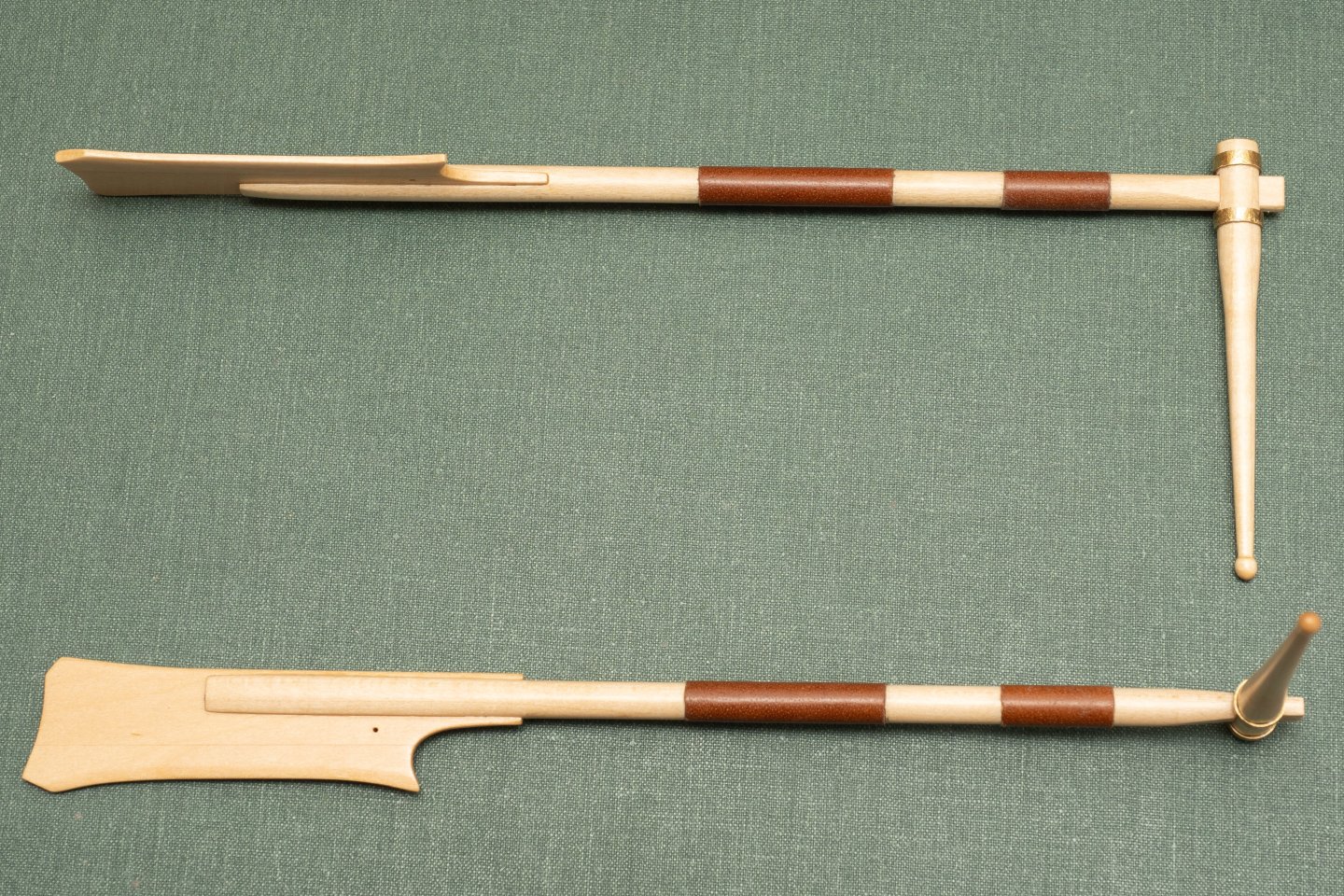
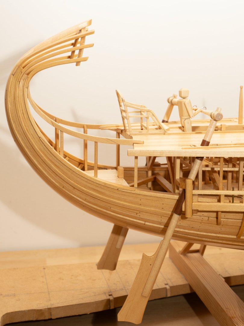
Steering oar and tiller assembly with metal bands and leather bearings: On Olympias they are fitter with lead straps around the steering oar blade to overcome buoyancy. I sourced some lead sheet of the right thickness (0.8mm equivalent to 18.5mm full scale...), which is sold for use as fishing line weights...However, reading about the disastrous effects of acetic acid on lead fitted to wooden models (Ref "Lead Corrosion In Exhibition ship Models, D. Wegner, NRG, Vol 43, No1), I decided against fitting. I will probably fit something made of brass at some point, but for the moment Im leaving as is... Here they are installed on the model, ably demonstrated by one of my trusty marines: On Olympias they are held up by ropes made off to the cleats either side of the helmsman, so that he can adjust the height of the oar (the hole for fixing these to the oar blade can be seen just behind the stock. I plan to fit thesee ropes once Ive made a decision on what rope material I am going to use.
-
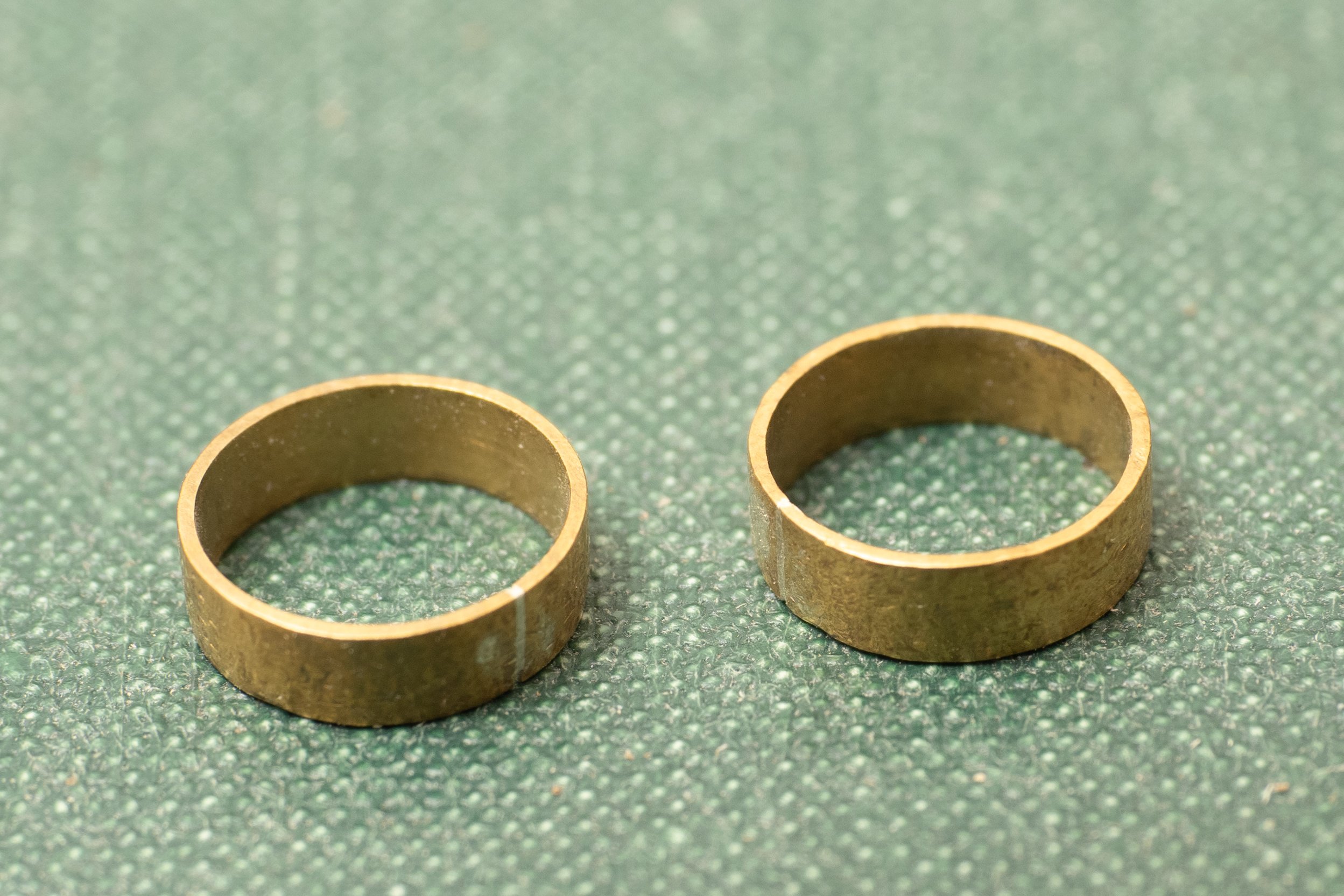
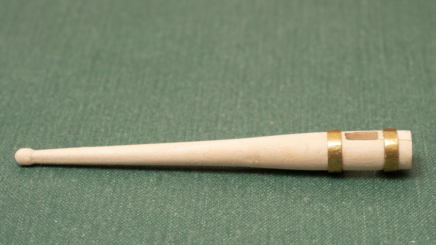
Making up some brass bands for reinforcing the tiller mortice. A bit of a refresher as I havent done any metalwork like this for some time. Process as follows: 1. soldered with a solder/flux paste in a syringe and heated with a small dremel blowtorch, which seemed relatively straightforward. although you end up with a silver line where the joint is (unsurprizingly!)... 2. made slightly undersize and lightly hammered on a mandrel until the right diameter to fit the tiller. 3. Pickled in acid and cleaned up with ultra fine wire wool. 4. Placed in a jar above some amonia for about 15 seconds which gave the brass quite a nice "bronze" look. Resulting rings ready to install: Here they are on one of the tillers:

-
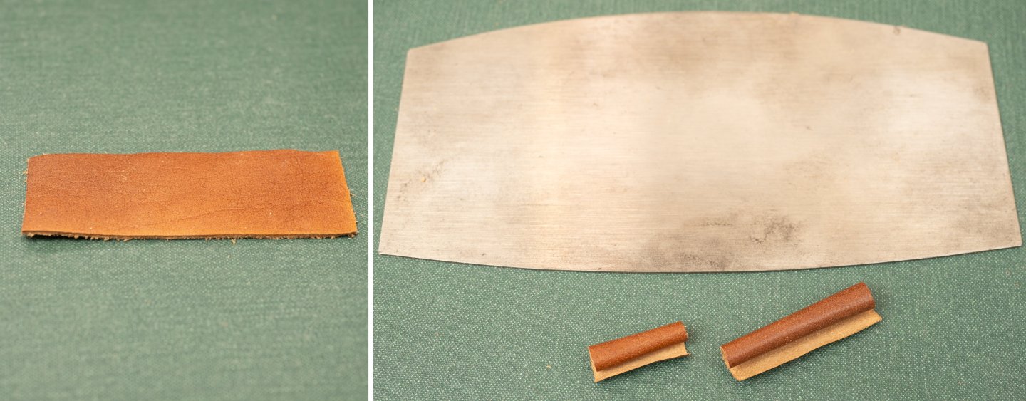
Preparing the leather for the rudderstock protection in way of the upper and lower bearings. Ive started with some leather (cow hide) about 1mm thick and thinned it down to about 0.2mm (approx 5mm thick at full size). It took a few attempts to do this without tearing the thin, fragile material. In the end I found it was easier with a large steer furniture scraper rather than a scalpel due to the more even "scrape". Now need to do some experimentation to find the best means of fixing (evostick or epoxy?) and final cutting to size (leather expands slightly when glue is applied to it). Photo below shows original 1mm hide and finished pieces (for upper and lower bearings) alongside one of the scrapers used.
- 319 replies
-
- 10
-
-
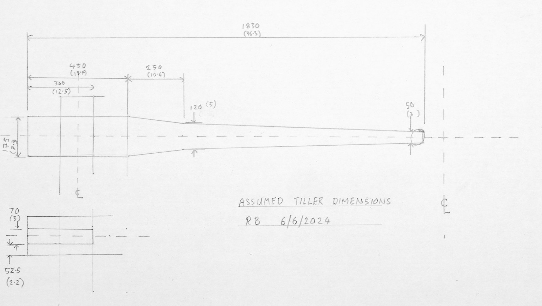
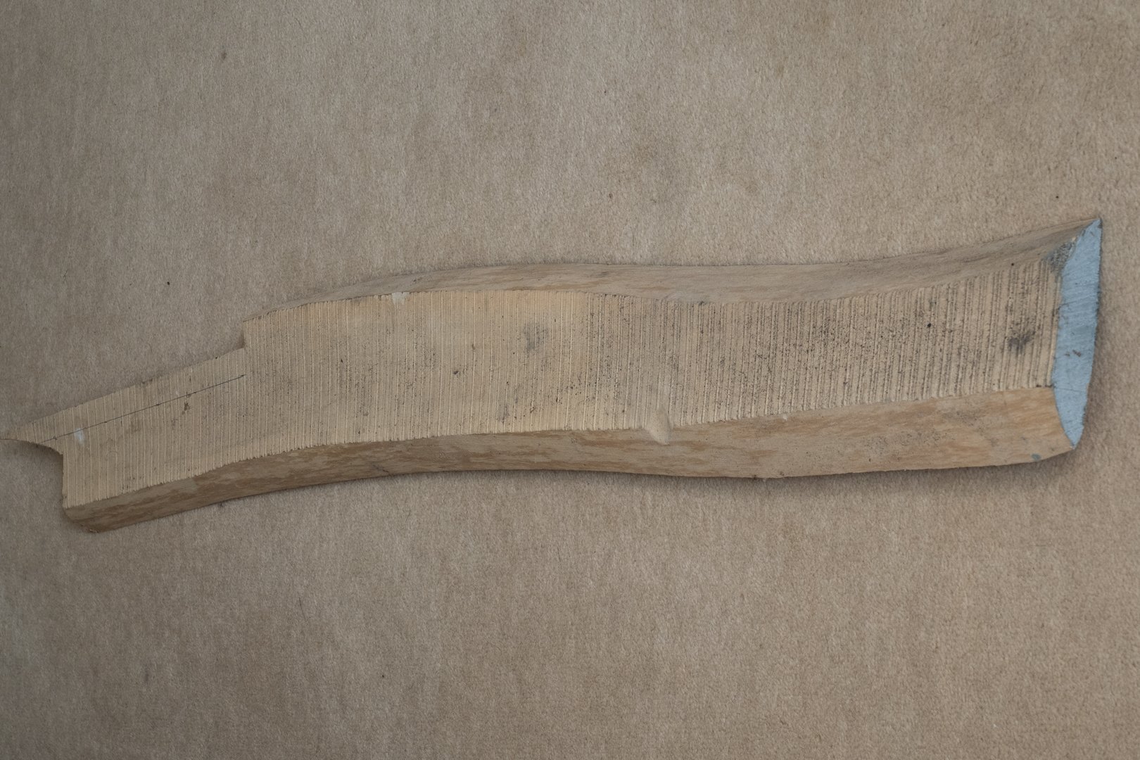
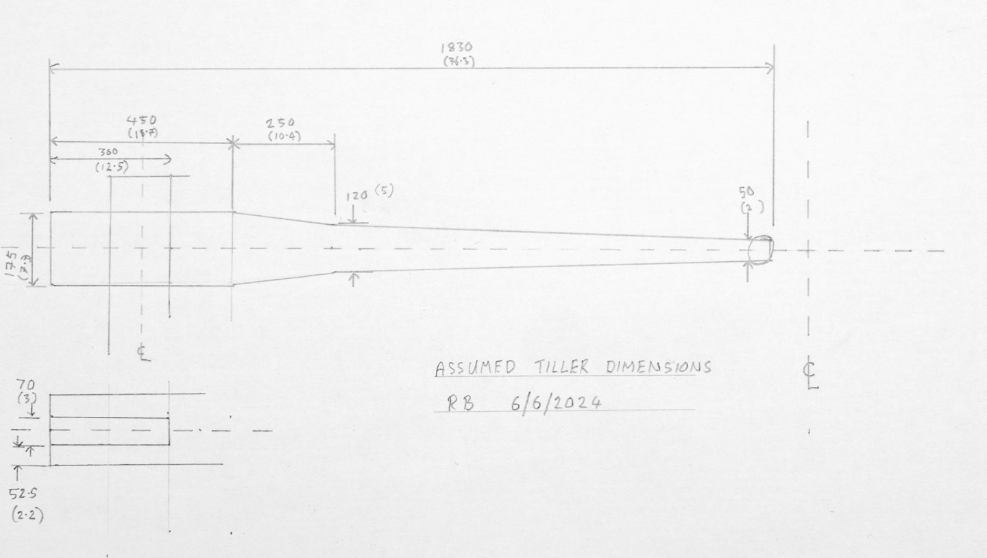
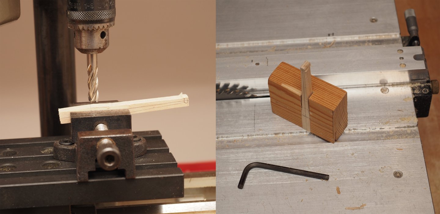
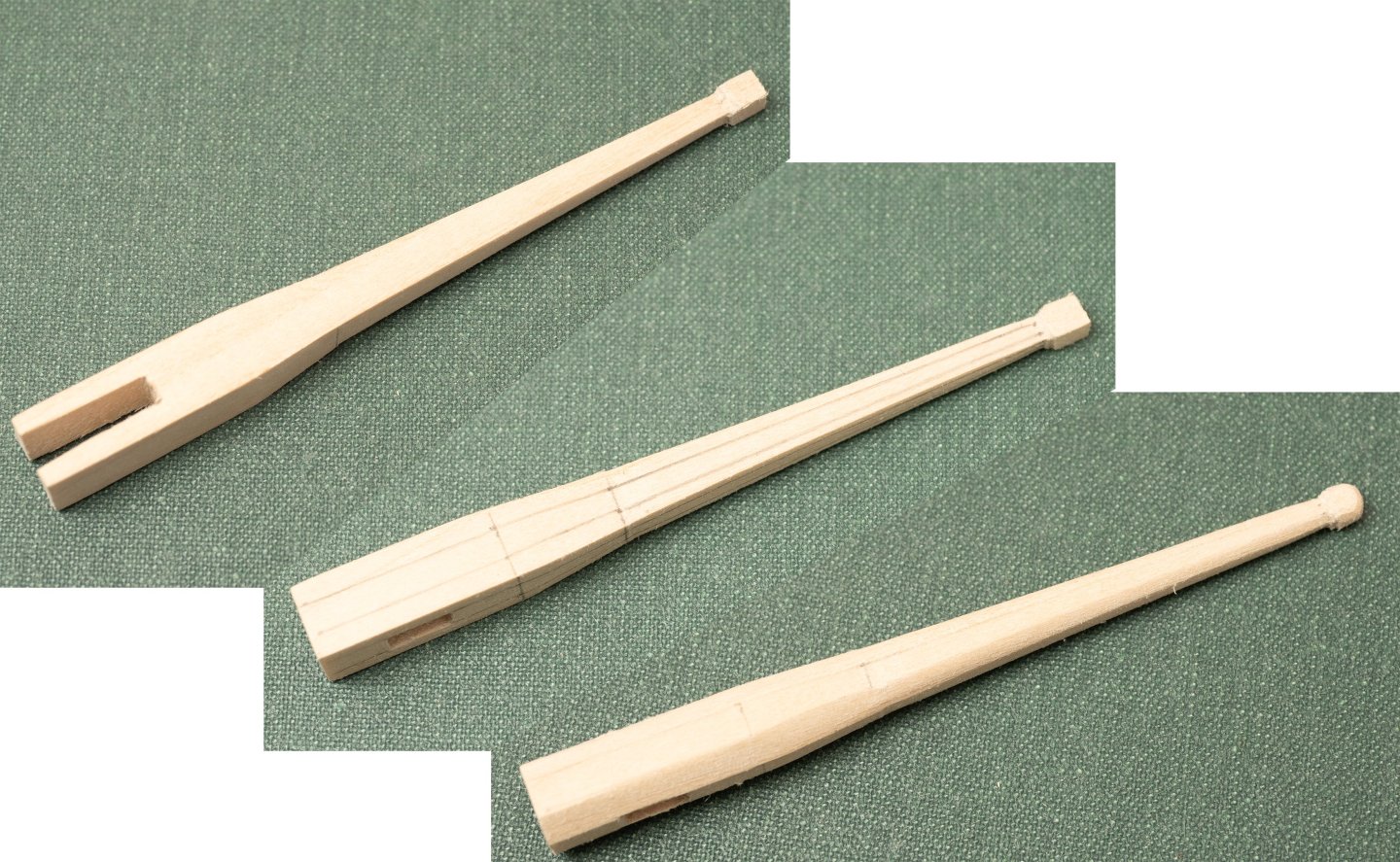
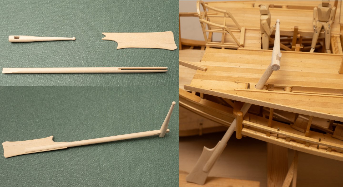
As mentioned above, the tiller is not completel;y defined in the John Coates drawing pack. The following sketch is my best guess at the dimensions from scaling from the drawings and photographs of the full size ship: I originally thought I would turn this on my Unimat, but evantually decided to mill the tapers and then round it by hand using the general method for shaping spars. The image belos includes a jig intended to hold the tiller squarely against the fence of my Byrnes Table saw for cutting the slot for the rudder stock tennon: Then rounded by hand in the usual way: Here are the components of one of the rudders (showing trial assembly on board) prior to fitting leather and metalwork:
- 319 replies
-
- 13
-
-
Back to work again after a travelling break... Unimat setup for milling the tennon at the head of the rudderstock:
-
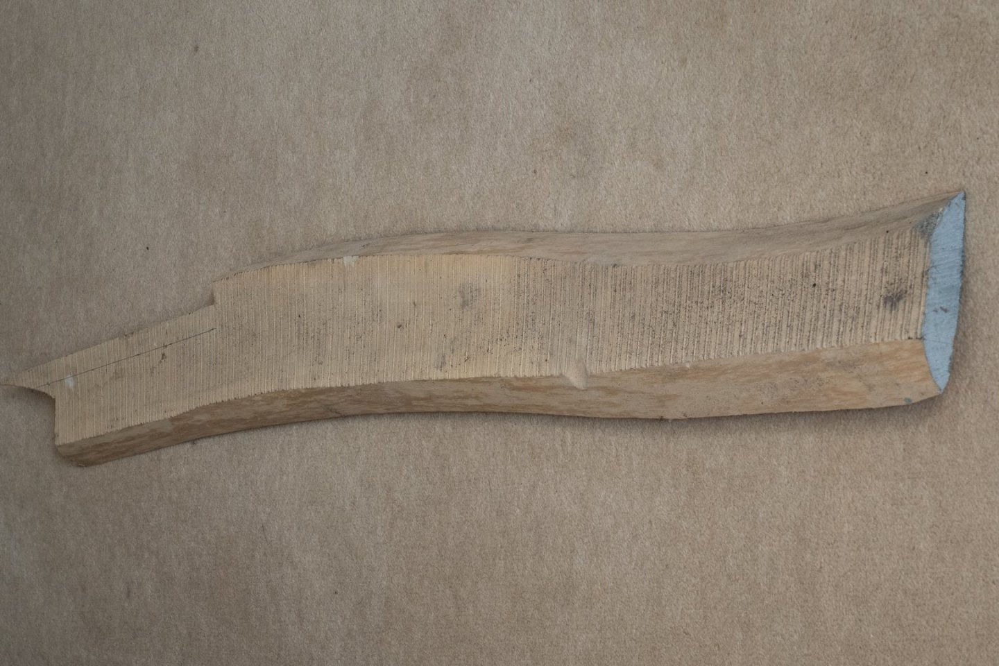
I sliced up a substantial holly log about 30 years ago. The log was 9 inches in diameter and I cut it into 1 inch thick planks. I sealed the ends with aluminium yacht primer (because I had a tin lying around...) and stacked the planks separated with 1" pine stock for drying. The planks did distort a bit during the drying process and a mould did develop over the surface during the first year (while the sap was still wet). I also remember getting quite worried that my lovely wood would be wrecked! However, as far as I remember, once it had dried I was able to brush the dead mould off the planks. 30 years later the holly is a lovely creamy white throughout. So Im sure yours will be fine in a few months time. I still have most of it left, awaiting a suitable project. The photo below shows one of the plank with a chunk taken out to make some of the finer bits of my trireme model (e.g. the Trierarchs chair https://modelshipworld.com/topic/21958-trireme-olympias-by-richard-braithwaite/page/4/ ) , where something harder and more precise than lime was needed. Holly is just about my favorite wood for model boat making. I think the grain does a passable imitation of oak in miniature and it can be carved as fine as paper if needed.
-
The text on the photos above was created in photoshop, which is the progam I use for general photo processing. There are lots of lower cost alternatives available however. Ive even found Powerpoint as quite an effective solution, particularly for lower resolution images where you can simply take a screenshot of the annotated "slide".