
Richard Braithwaite
-
Posts
229 -
Joined
-
Last visited
Content Type
Profiles
Forums
Gallery
Events
Everything posted by Richard Braithwaite
-
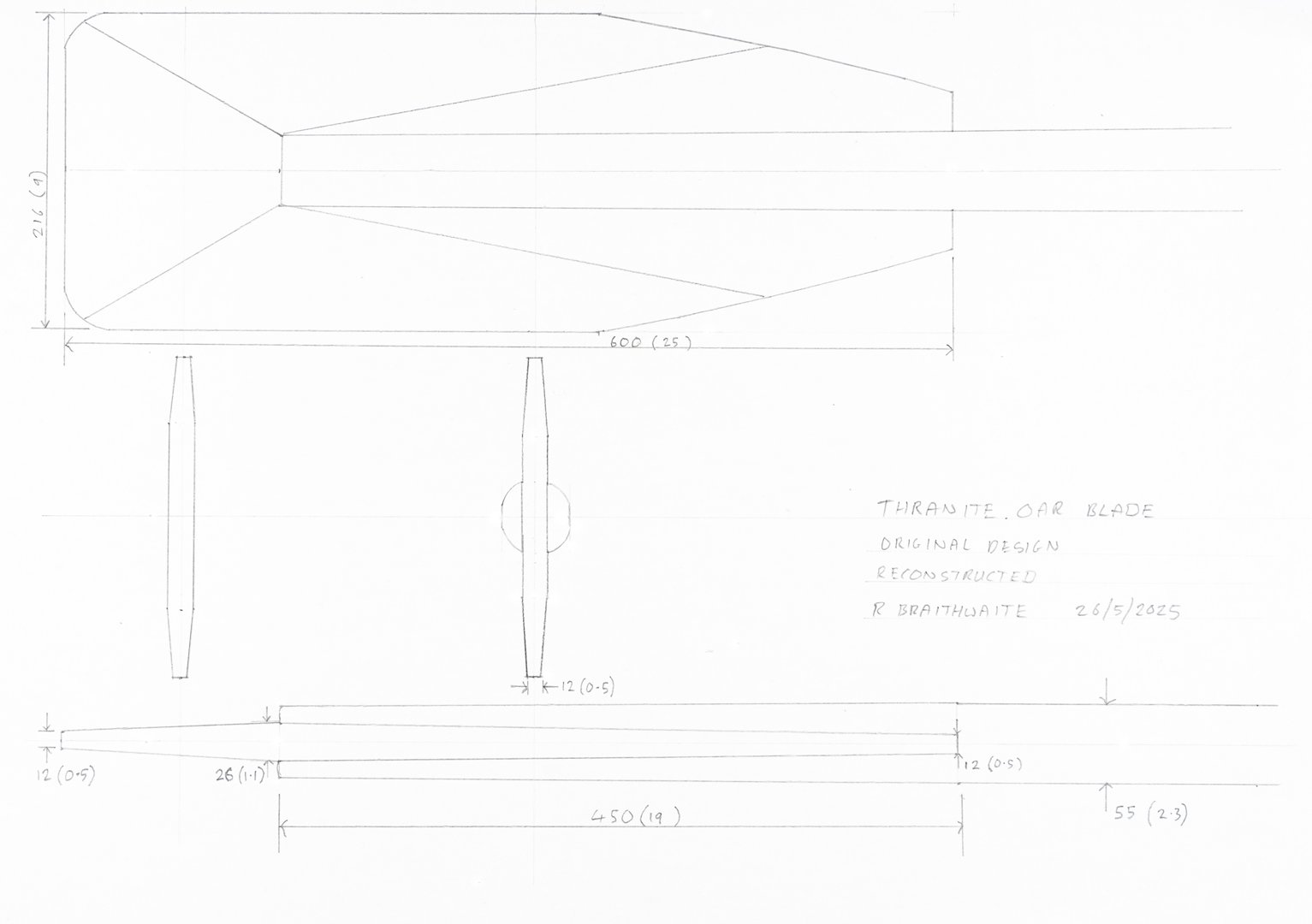
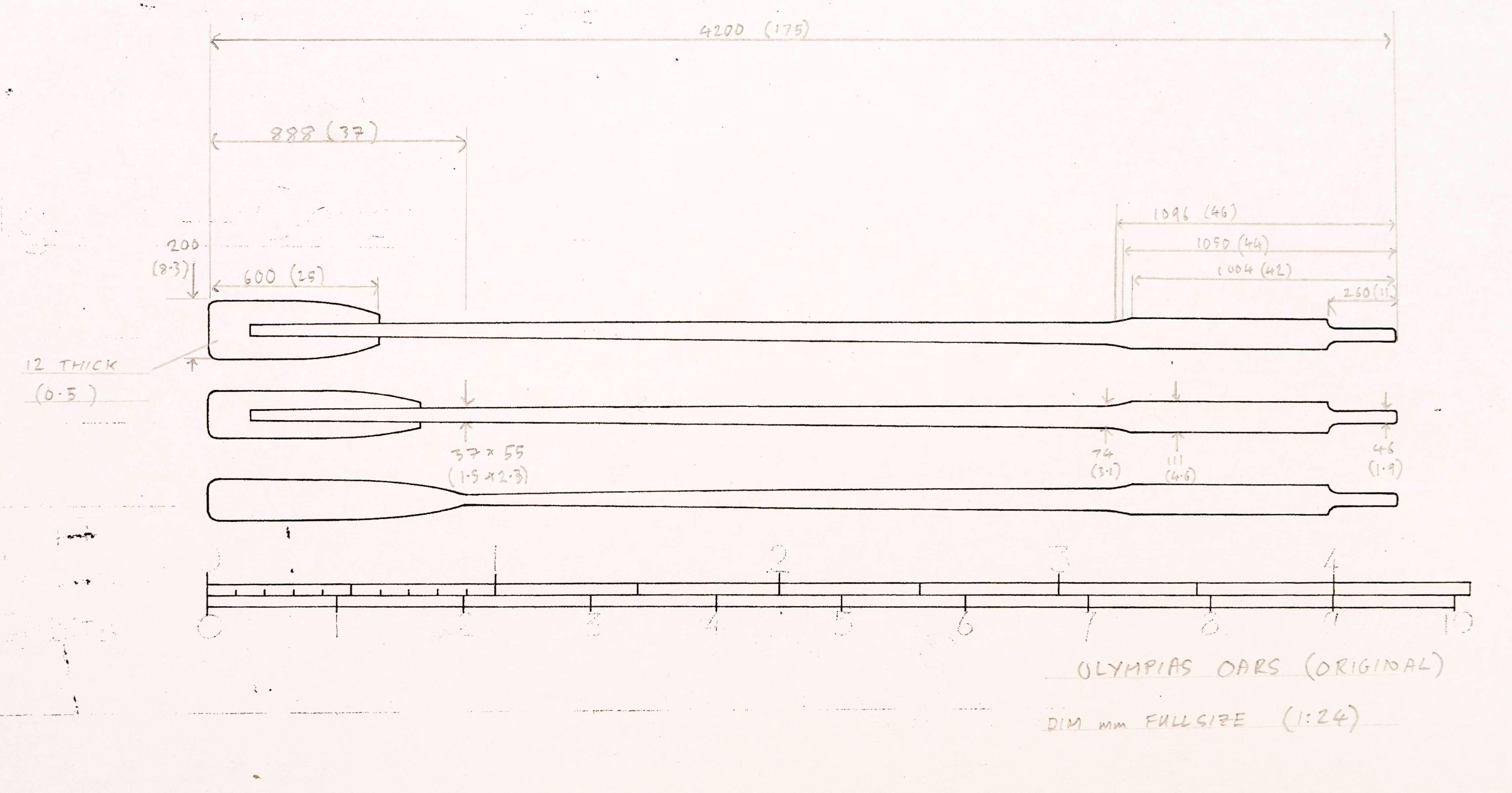
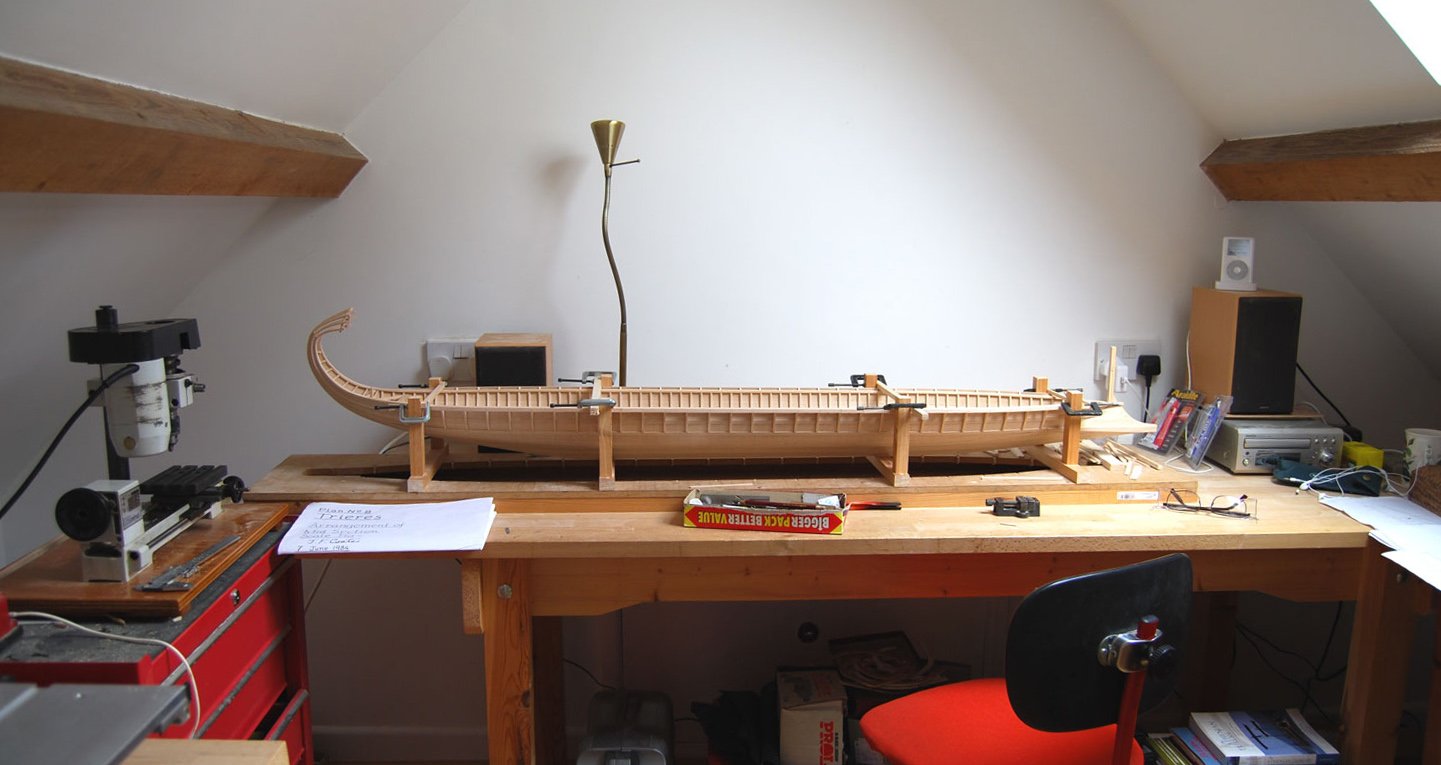
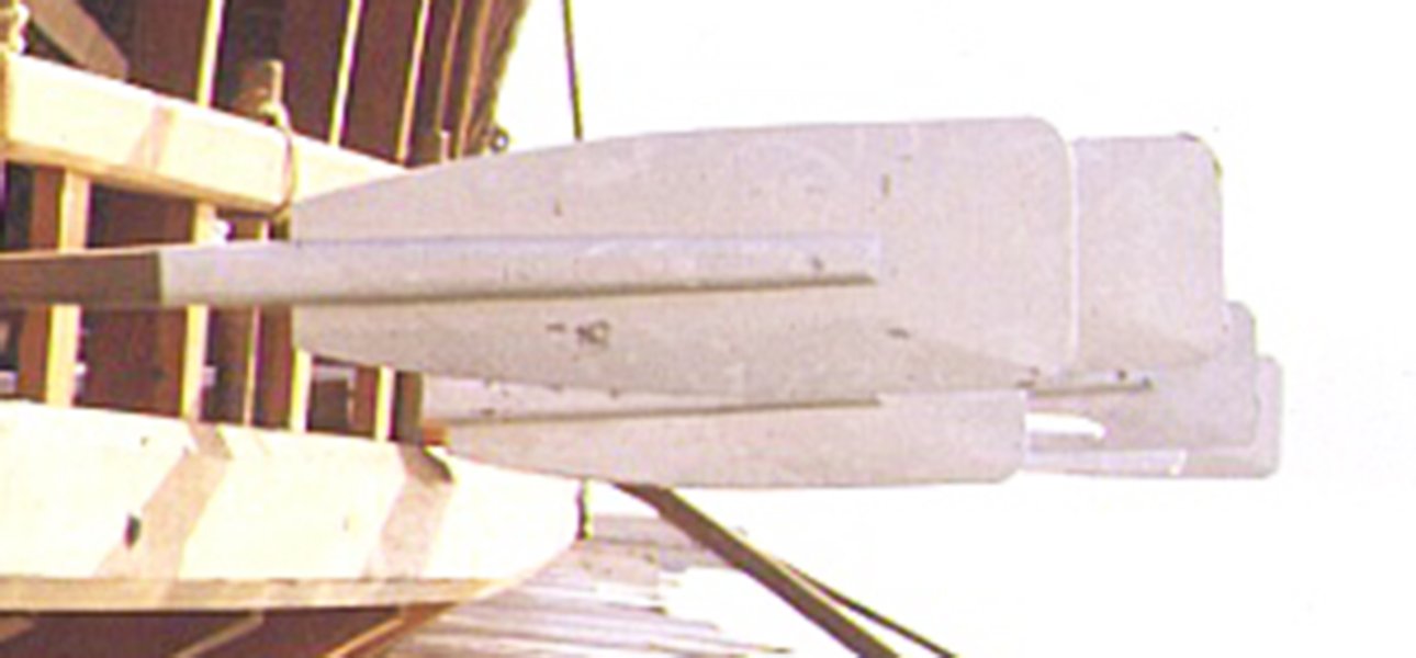
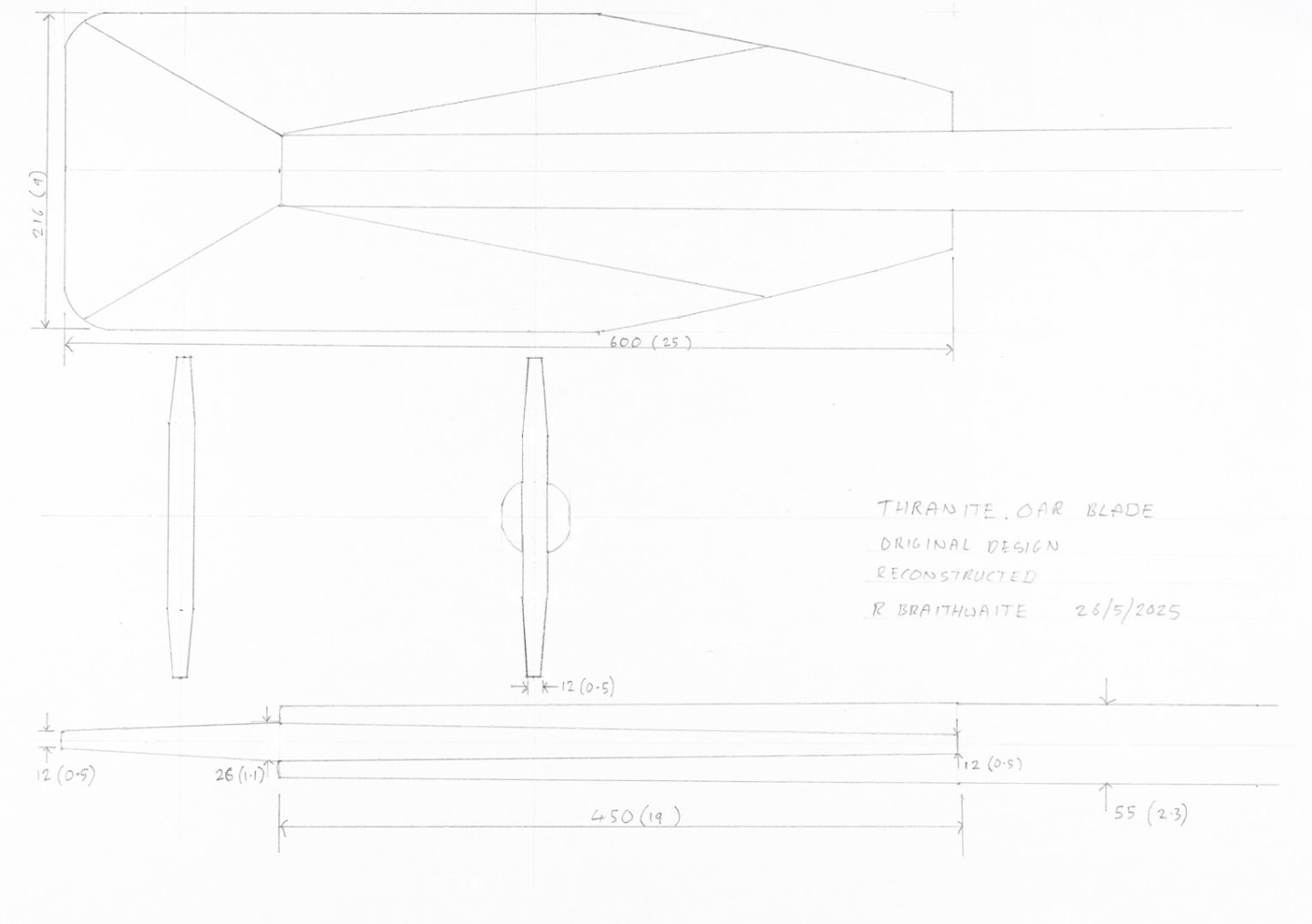
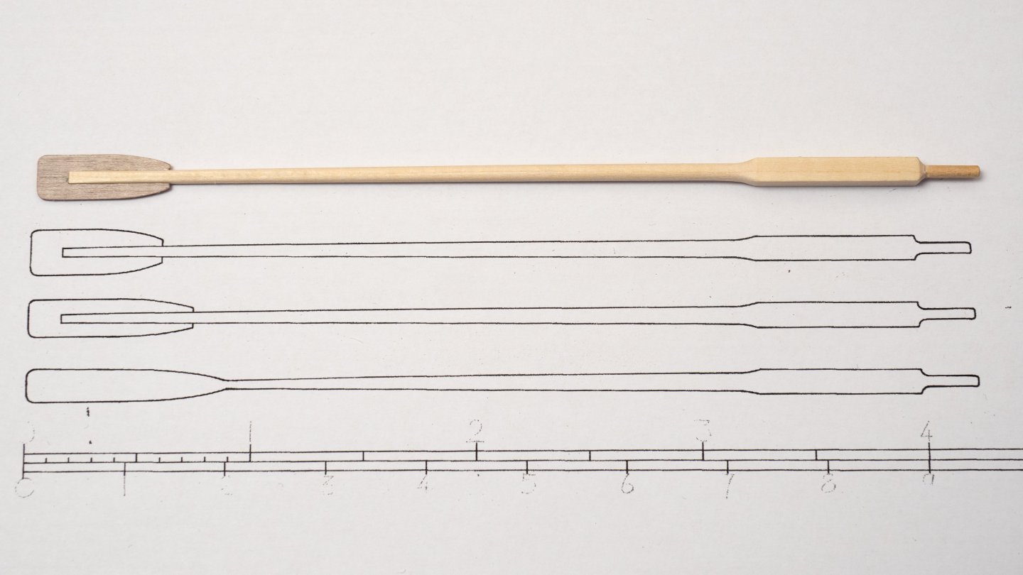
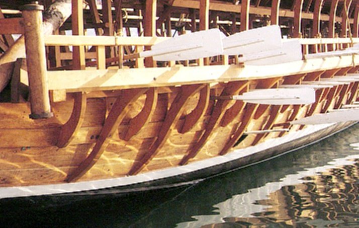
 Finished fitting 62 handles to the Thranite oars... Now rethinking the blades. I havent been able to find drawings of the original Thranite oars in the Trireme Trust Archive. However there is a drawing showing how these were modified in 1989 to reduce their weight from 17kg to 6 kg by shaving down the shafts, and reducing the thickness and area of the blades. Extracts from the Midhsip Section (Plan 8 ) and the Modified Oar drawing (Plan 15e) show how the form of the blade was altered. The upper plan view is of the original form and the lower plan and section shows the modified blade. Extracts from Plan 8 and 15e( © Estate of John F. Coates, reproduced with permission) The oval form of the blade was also intended to make them slide over one another more easily to reduce entanglement. As you can see from the section view the blades were not simple flat pieces of wood, as I had originally planned for my model, but were tapered. The form of this tapering in the original design is sugested by this image of the full size ship. Ive reconstructed this form in the following sketch for my model: The lines in the plan view radiating from the end of the shaft prongs show the edges of the tapered faces which I will need to machine in the blades, although the photograph sugests that the inner faces were faired to remove any hard edge. So, I now need to make up some more jigs...
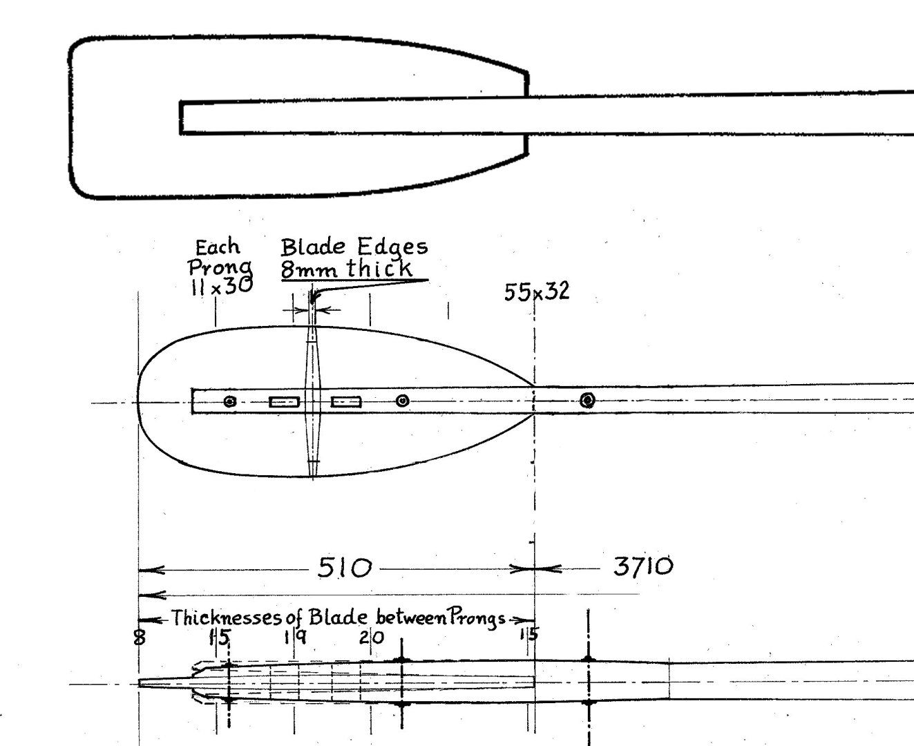
-
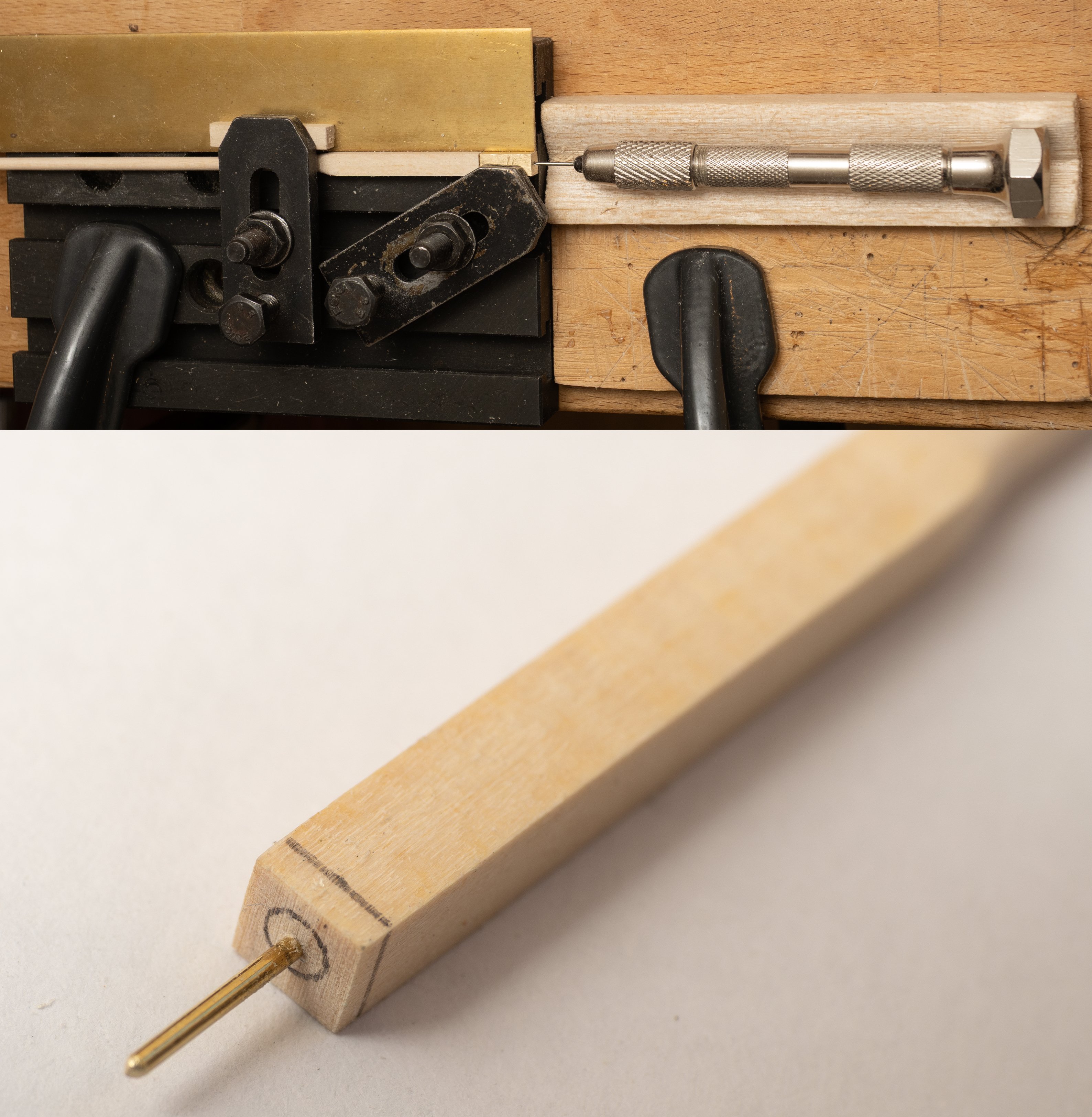
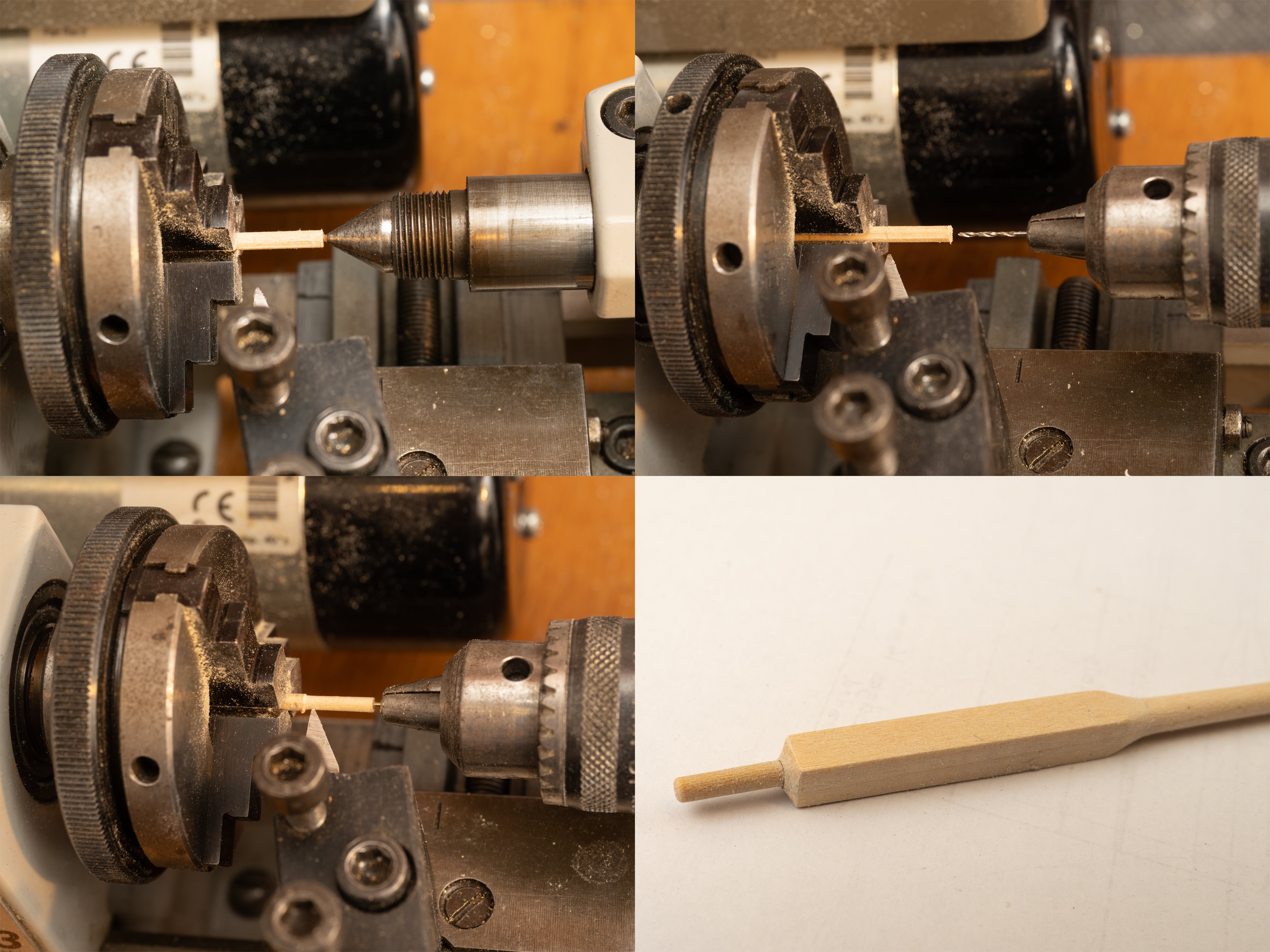
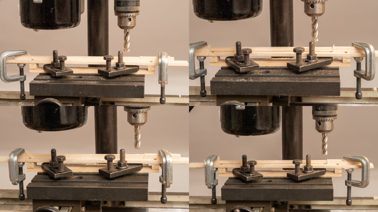
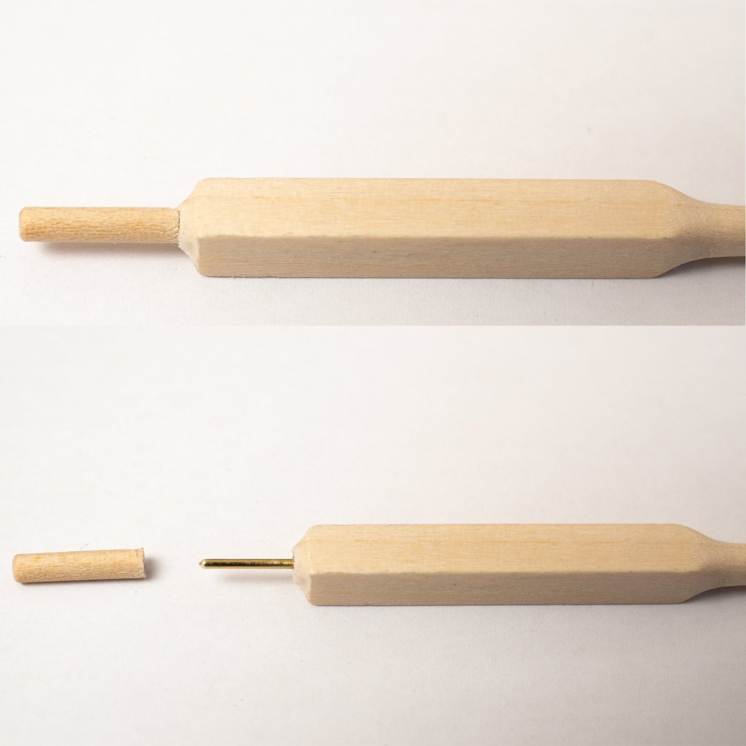
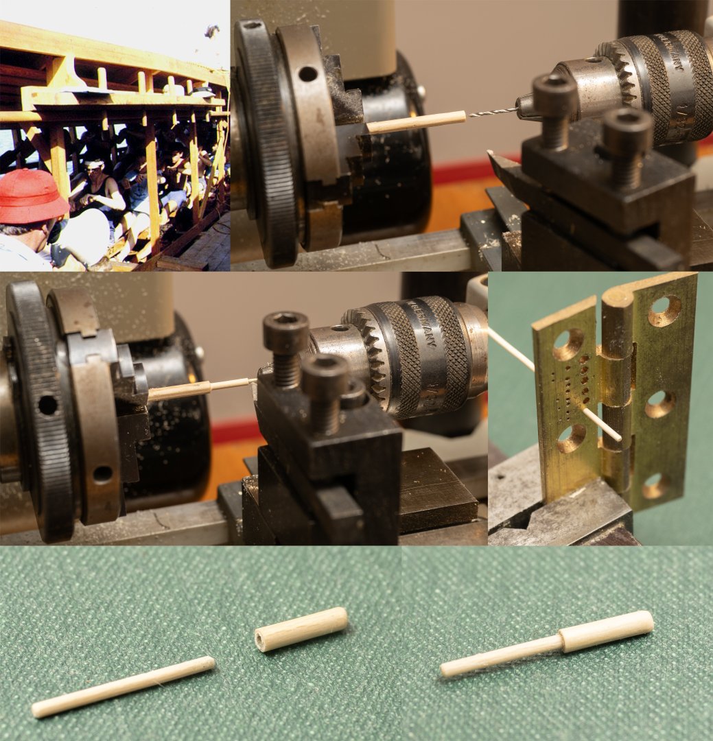
So, 62 oar shafts all tapered and rounded.... Next stage, making and fitting handles: The oar shaft is drilled to take a brass rod to act as a core for the removable handle and also as a bearing to the connector that will hold the oars in place within the boat. I machined a brass section to the same dimensions as the oar shaft drilled at its center to enable the drill to be properly aligned with the center of the oar shaft as shown below. The second image shows the brass rod in place and the oar shaft marked out for shaping the transition to the handle The oar handles are then drilled and turned befor fitting over the brass rod on the oar shaft as follows: The total time taken for all this is about 0.5 hour (if I'm working efficiently!). (Total cummulative time/oar, so far 2.25 hours...)


-
Boudriots 74 gun ship series are some of the loveliest books out there. Real works of art in themselves... Your model really does them justice and its a real joy to see such craftsmanship. Its also reassuring to see other people out there spending decades building a model!
-
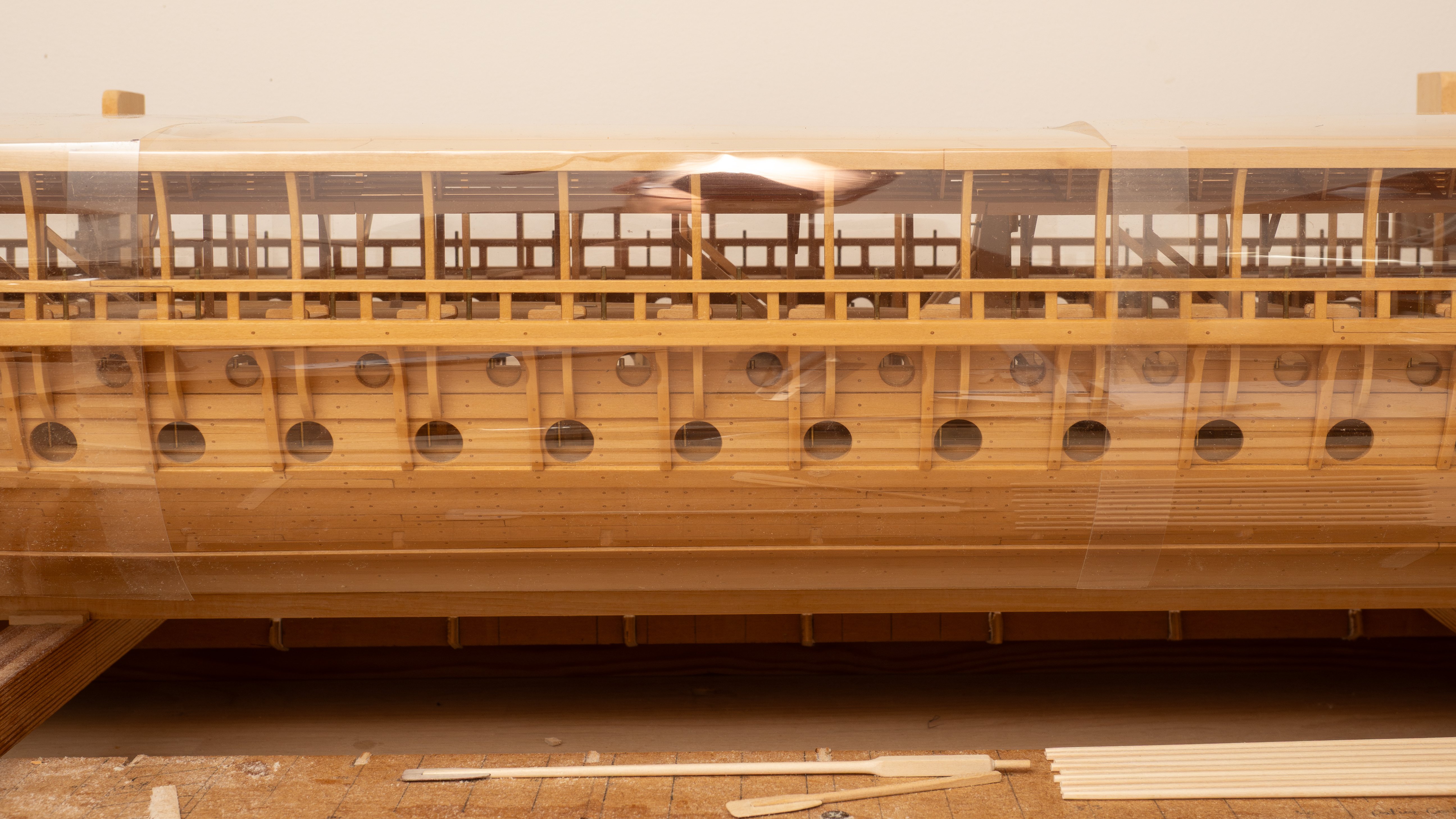
Im creating quite a lot of sawdust at the moment... So, improved dust protection of model required (it took a lot of time to hoover out all the accumulated dust and clean before I varnished last year...). I also wanted any cover to be transparent so that any darkening of the model (now its varnished) will be even. Found these 0.19mm Acetate Mylar sheets (300x600mm), which folded quite neatly over the deck (extending over the sides and covering all the oar ports).

-
Your ship is looking fantastic. I built the hull of my "Olympias" model is a similar way (planking first and then frames made to fit). My log starts after I had done this, but I think ive included some description somewhere... Interested to know if you made those frames to fit your planking or made them from patterns and then pulled the planking to fit them? I remember working on an old steel ship, which we were rebuilding to make a different sort of ship... I had designed a substantial, cambered frame to fit under a thin, lightly stiffened deck. Our shipwrights tried to fit it on a hot day. They made the frame with some extra material ("green"), craned it into place, marked it off to fit the undulations of the (old battered) deck and then took it back to the dockside to cut it to their marked shape. When they craned it back on board they found that the deck had changed shape (the sun was now shining on it from a different direction...). So they marked it off again and repeated the process. After repeating this a few times they had cut off all the "green" and then some. They called me to come down to the ship and asked it I minded that the frame was now quite a bit smaller than I had intended... The next day we tried again. We cut a new frame to the design shape (no "green") and pulled the deck down to fit it. Your hull planking is very light, have you had any difficulties with distortion as you fit your frames?
-
Apologies if ive missed it in your log, but what have you used as fastenings for the planking? It looks very effective.
-
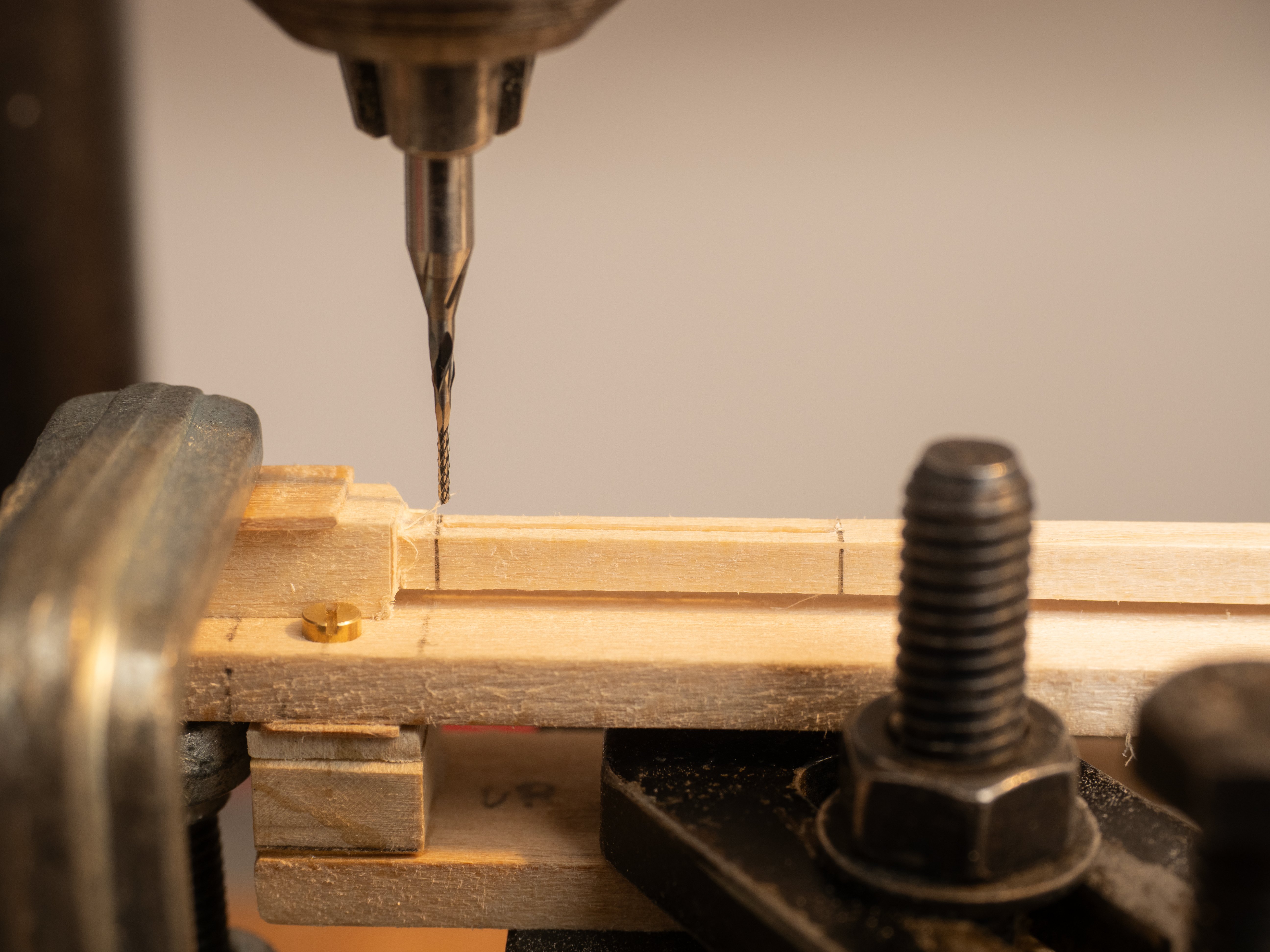
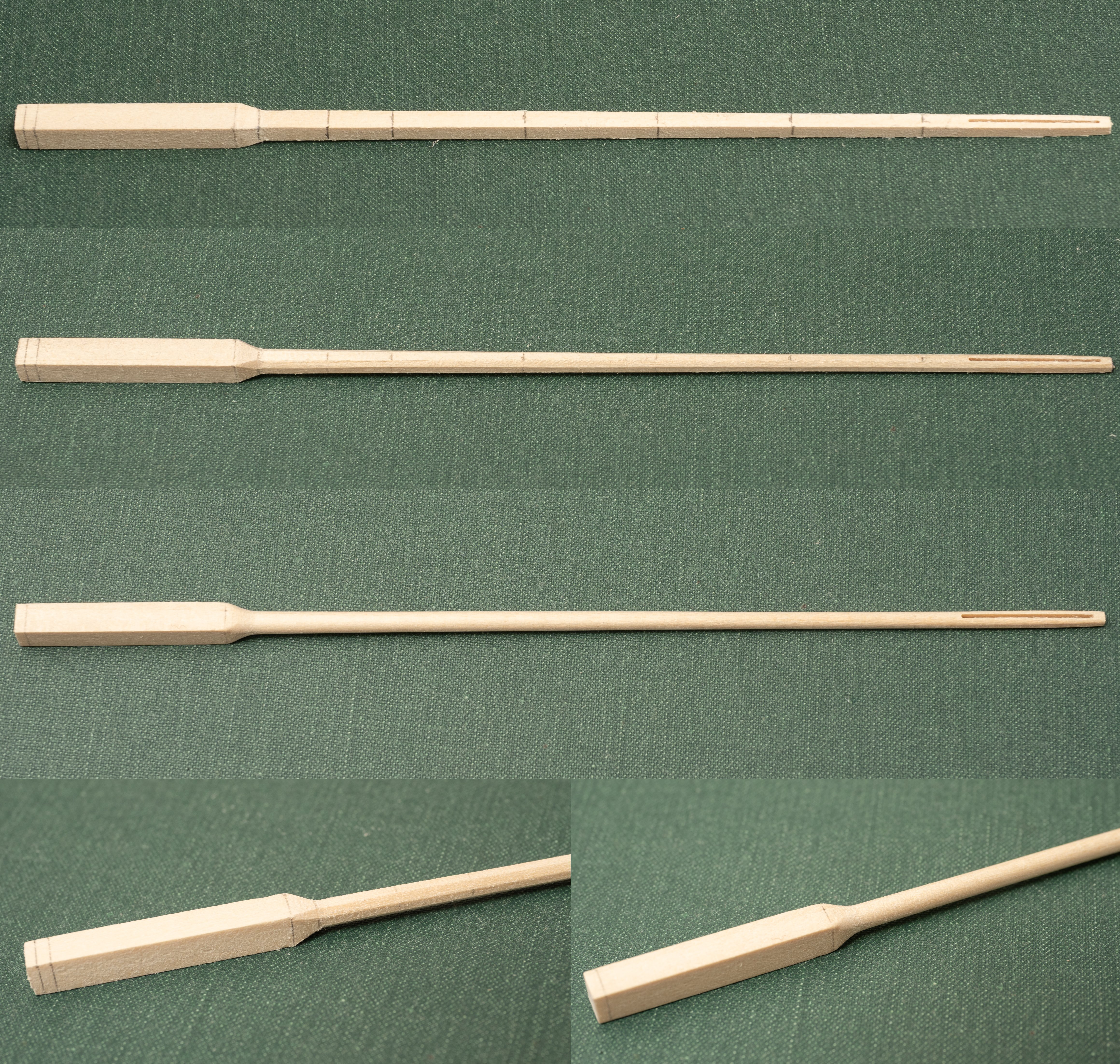
Next stage of making oars: 1. Mill the slot for the blade using a 0.5mm cutter: 2. Cut off end of oar (leaving a small part beyond the end of the oar slot to aid stability during shaping) and sand the shaft down to finished square section dimensions, including the transition from inboard oar loom to outboard shaft. 3. Mark up with "indicator" pensil lines along the shaft to assist with "octagonalising". 4. File/sand off corners to make an octagonal section (including the transition from the square section loom to the outboard shaft. I find the "indicator" lines helpful with getting the faces of the octagon even, aiming to get the resulting "dashed line" around the staft even. 5. Round the shaft until the indicator lines just dissapear (indicating the final dimensions all round have been achieved). 6. square off the end of the loom to the final dimension to accept the oar handle (this will still require finishing to transition to the round handle, once the handles are fitted). Total time for all this approximately 45 mins/shaft (Total cummulative time/oar, so far, 1.75 hours)

-
I wont be overcoating the white enamel paint with varnish this time. Just trying to decide what to do underneath it. Have heard that a shellac primer might help prevent pigments coming through.
-
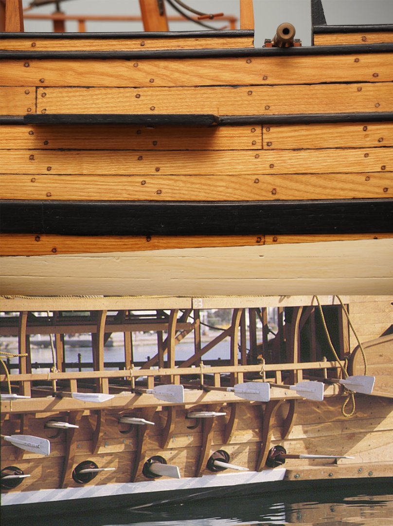
The upper image in the picture below shows some wood (Ash) that I painted 40 years ago. All the planking was coated with about 5 coats of polyurethane varnish and a couple of coats of black/white Humbrol Enamel was applied directly on top with a further coat of polyurethane varnish on top to proect it. As you can see the white paint has discoloured slightly , Im not sure whether this is due to the yellowing of the polyurethane on top or pigments comening through from underneath... The lower image shows part of the full size Trireme reconstruction "Olympias". I am building a model of this vessel (Trireme Olympias by Richard Braithwaite - - Subjects built Up to and including 1500 AD - Model Ship World™) . The model is finished with polyurethane varnish and I need to decide how to finish the oars (varnished shaft, white painted blades) So far Im thinking of two alternatives: 1. Coat the entire oar (blade and shaft) with polyurethane and then coat the bade with primer and overcoat with white enamel. 2. coat the shaft with polyurethane up to the boundary with the blade. Apply primer to the bare wood of the blade and overcoat with enamel. The second option would make most sense in terms of keeping the different paint systems separate, but I suspect i could do a neater job with the boundary with the first option. What experience do you have with this sort of paint scheme?
-
Very neat. Rather more elegant than the graph paper plot followed by tricky manal dial turning i have used for complex machined shapes! I did think of making this jig from brass/ aluminium. But, so far, my quick wooden effort seems to be stiff and durable enough... Have you had any success turning tapers on long slender wooden shafts such as oars and spars? If i could make that work it would be much better than what im doing ( machining to a square taper and then manually " octagonalising" and rounding). However, whenever ive tried turning this sort of thing it fails due to vibration/ flexing.
-
First stage of oar production. The jig bolts onto the milling table of my Unimat and allows for different tapers to be milled by fitting a spaced under the bolted on top piece. 4 setups required per oar shaft to taper each side (so the jig has to last for 4 x 170= 680 setups and clampings - hence protective strips of wood under clamps!). Each oar shaft takes about 1 hour to machine to a square taper (including marking up) with the milling cutter making 5 x 0.2mm cuts per side. The cutter could certainly manage deeper cuts on this soft wood but 0.2 mm seems the most I can safely do without too much vibration and sideways deflection of the oar shaft (particularly the last few cuts when it is at its most slender). A wedge is fitted underneath the tapered part of the shaft for alternate sides to prevent vertical deflection. (wedge machined to the same taper - using the same jig.) The image below shows the setup after each of the 4 sides have been machined. The supporting taper can be seen fitted under the shaft on the images on the right (2nd and 4th setup)
-
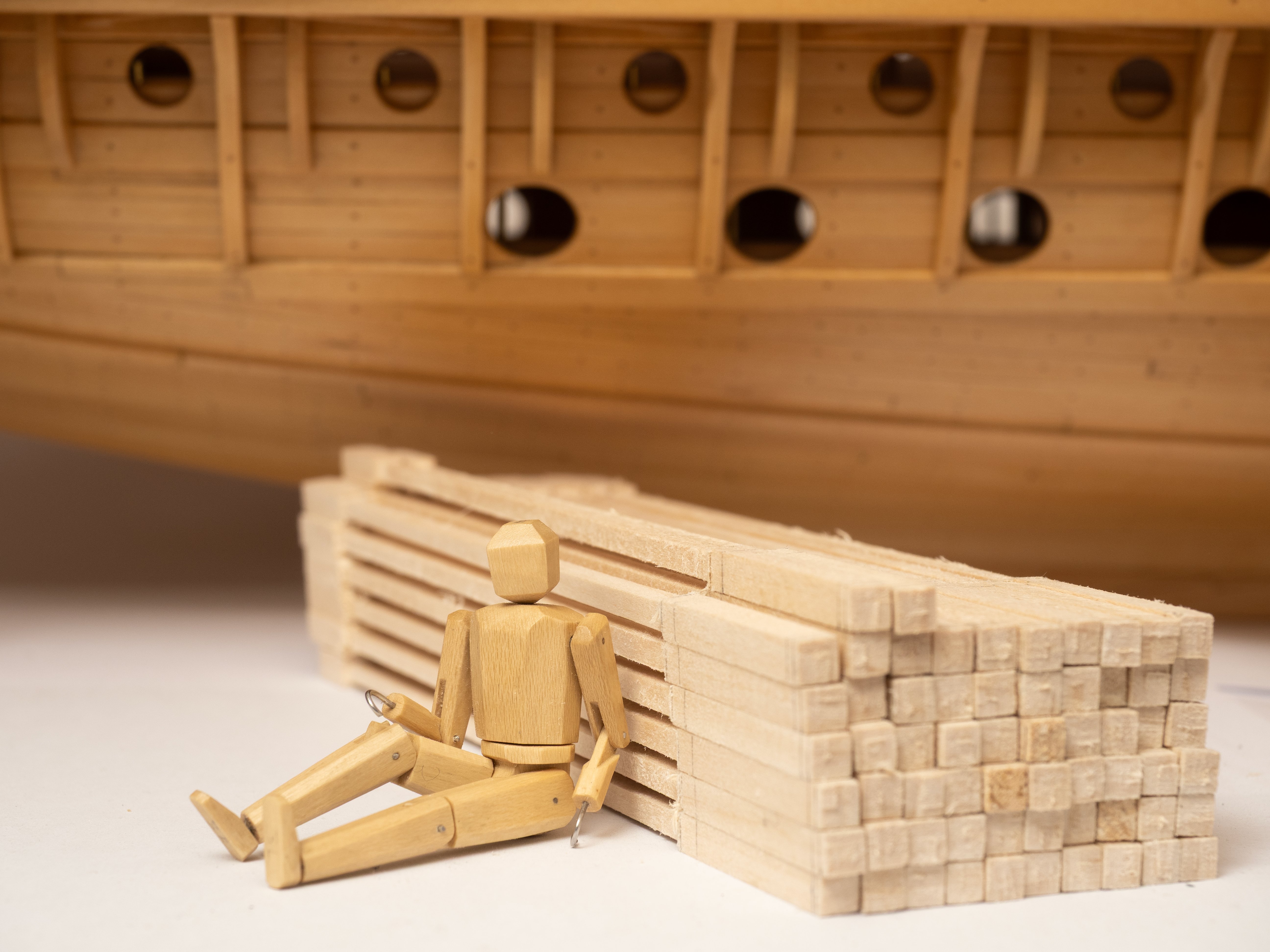
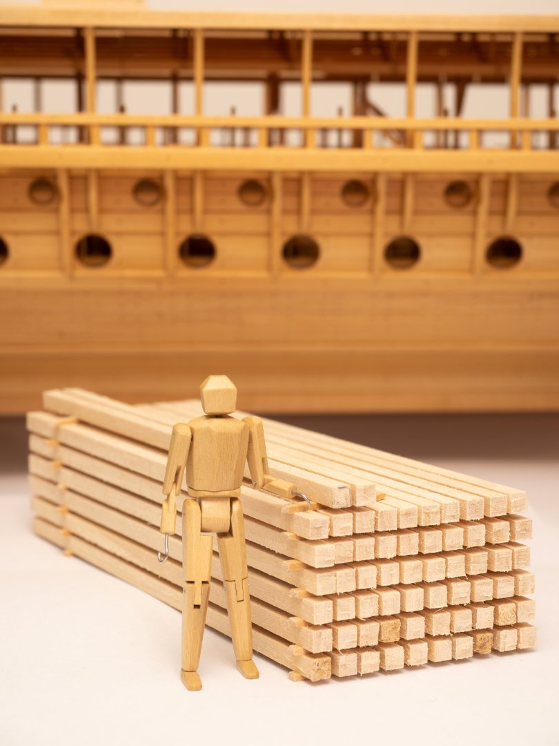
Spent the day milling timber for the Thranite oars using my Byrnes Table Saw , starting with a nice close grained, 30mm thick plank of lime that Ive been using for the spars and intend to use for the oar shafts. Here is one of my Athenian marines posing by the stack of timber that I now need to convert into 62 oars for the top level of my ship. After Ive done that there is only another 108 to do for the other two levels... - quite a daunting prospect... I must say, building this model has increased my respect for the Anthenians and the way in which they managed to build such large fleets of ships so quickly (and all those oars!!)
-
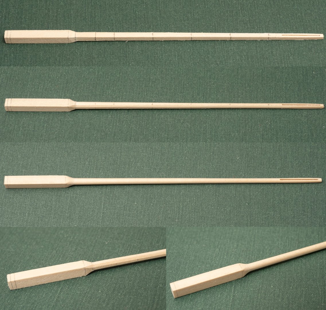
Ive been working on a pre-production prototype Thranite oar alongside developing jigs for making copies. The shaft is made of lime (like the bulk of the model) with a blade from 0.5mm birch plywood (from Home & Distant Models https://homeanddistant.com/ ). The handle is removable with a brass pin fixed to the loom of the oar which I am planning to use to connect to a longitudinal brass strip to hold the oars in place: The blades on the oars of Olympias are painted white and Im planning to do the same, so the missmatching colour of the birch ply will be concealed! Ill post pictures of the production process with the jigs in use as I go making the 62 Thranite oars required...
-
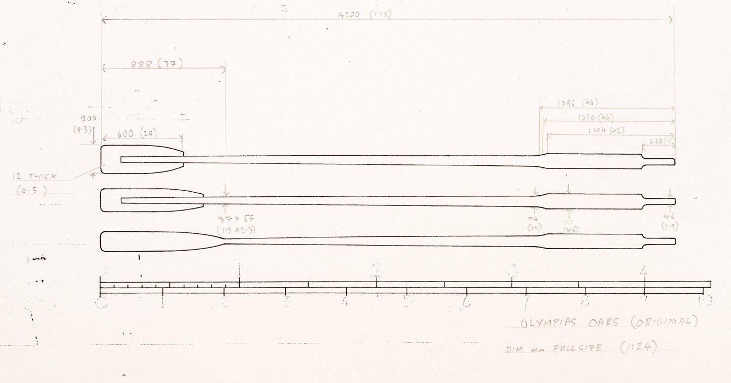
Now starting to think about the oars. I have the following numbers to make: 62 Thranite oars (upper level) 54 Zygian oars (mid level) 54 Thalmian oars (lower level) Im planning to build them according to the original design (they were changed for a lighter design for the last trials). Plan No 15 gives the dimensions for the Thalmian oars (which were made from a single piece of wood. There is an unnamed sketch showing all three levels which I have annotated with these dimensions as shown below ( ‘© Estate of John F. Coates, reproduced with permission.) Its a lot of oars, so now thinking of jigging arrangements for making them as consistent as possible and reducing the labour involved...
-
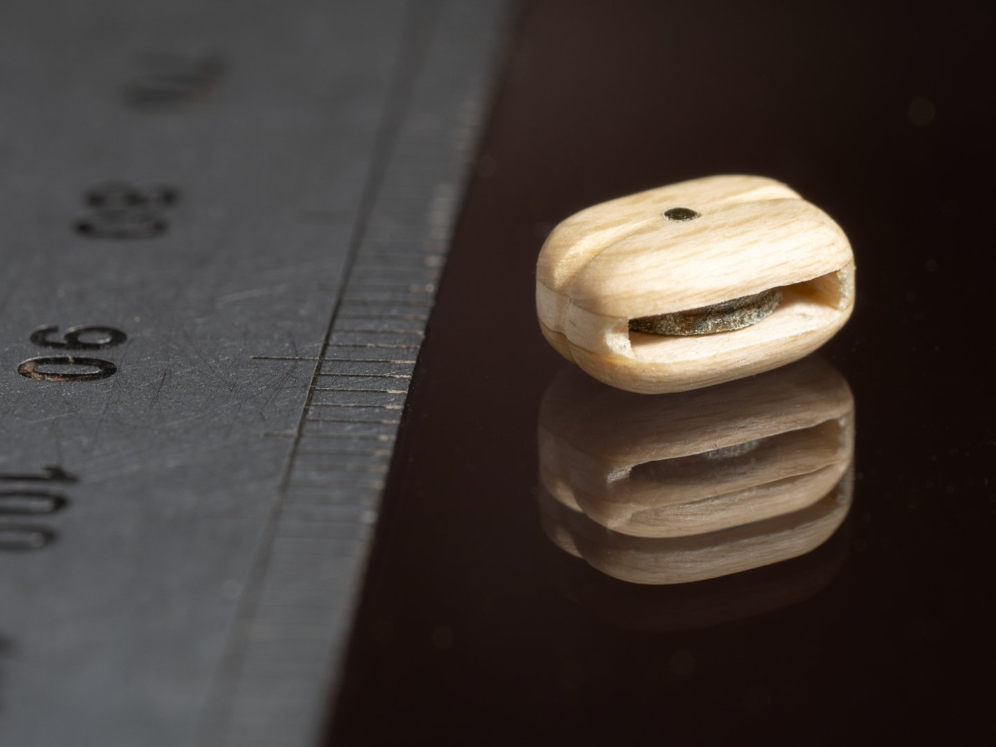
All 8 blocks completed and varnished. Rather confusing double reflection in the glass in this photo... Ive tried the blocks with Ben's 0.8mm poly rope and the lignum vitae sheaves run satisfyingly smoothly on their lignum vitae pins!
-
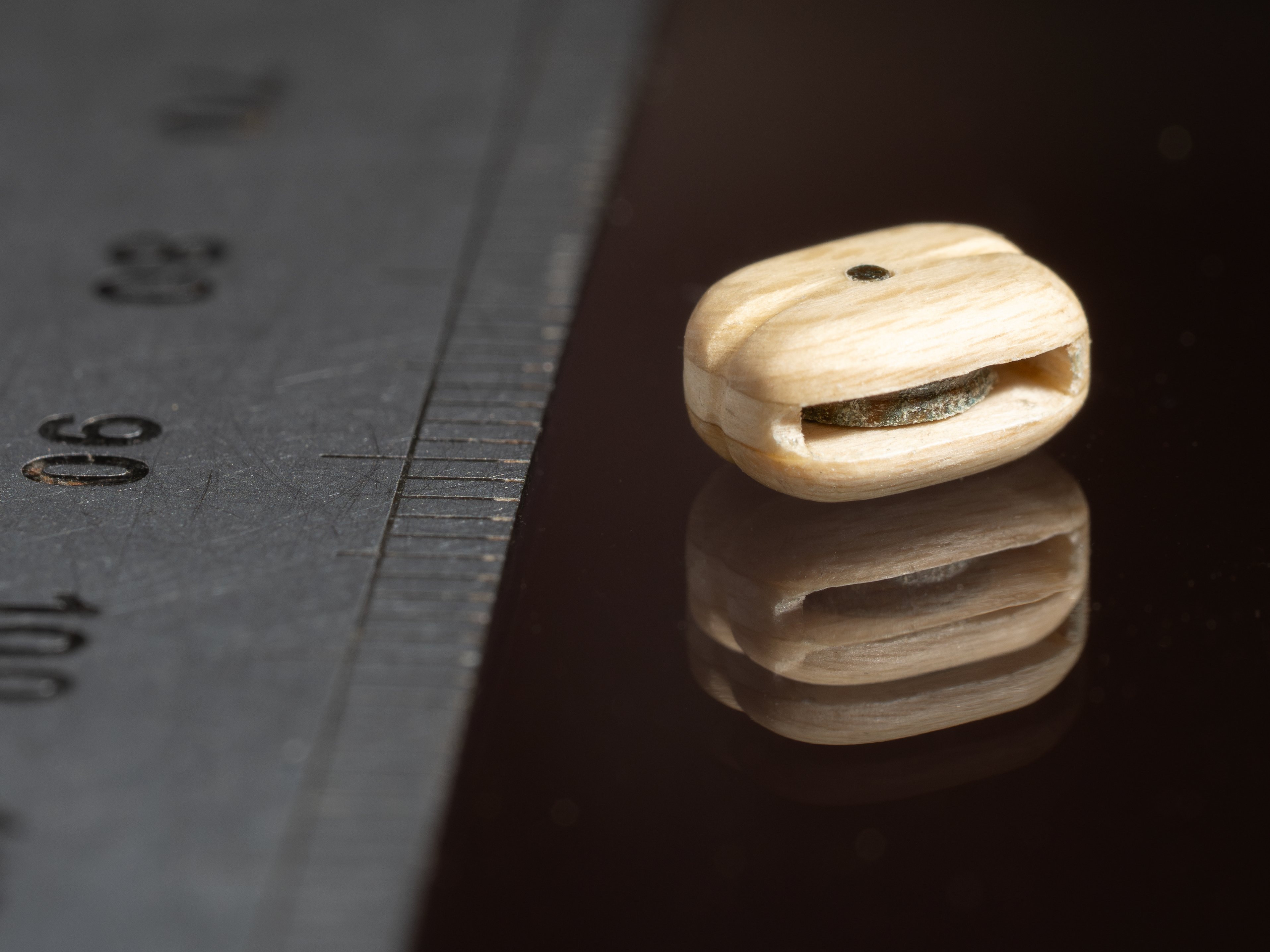
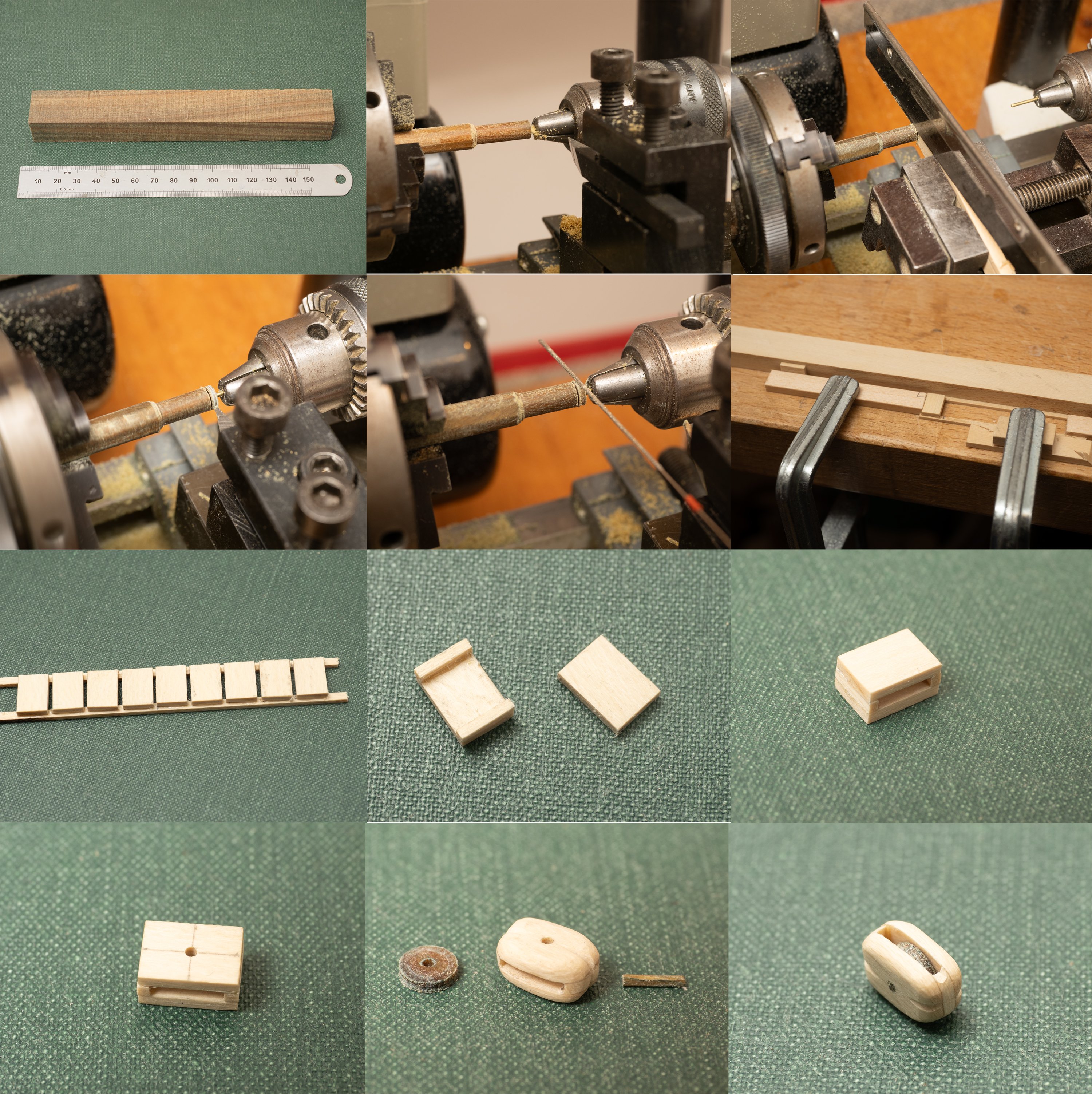
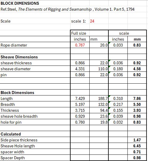
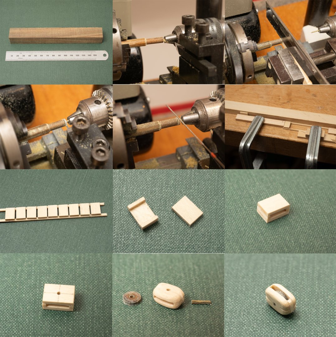
A block making interlude...(Another displacement activity as an excuse for not starting on the major project of tackling 170 oars...). The blocks on olympias dont try to reflect 600BC practice and are based on 19th century rigging. I only need 8 blocks (for the main and boat yards) and following table gives the relevant dimensions for the rope size specified: Reading Steel I noticed that the sheaves and sheave pins were made of Lignum Vitae. A google search showed that this could easily be purchased as "fountain pen blanks" so decided to give it a try. When it arived I could see why. Its a hard dense oily wood. Good material for bearings. Feels a bit like the tufnol material that is used in some sailing yacht blcock sheaves. The blocks themselves are made from Holly. The images below show the approach used. Just about doable at a scale of 1:24. Not something I would want to try for a model of HMS Victory at 1:48...
-
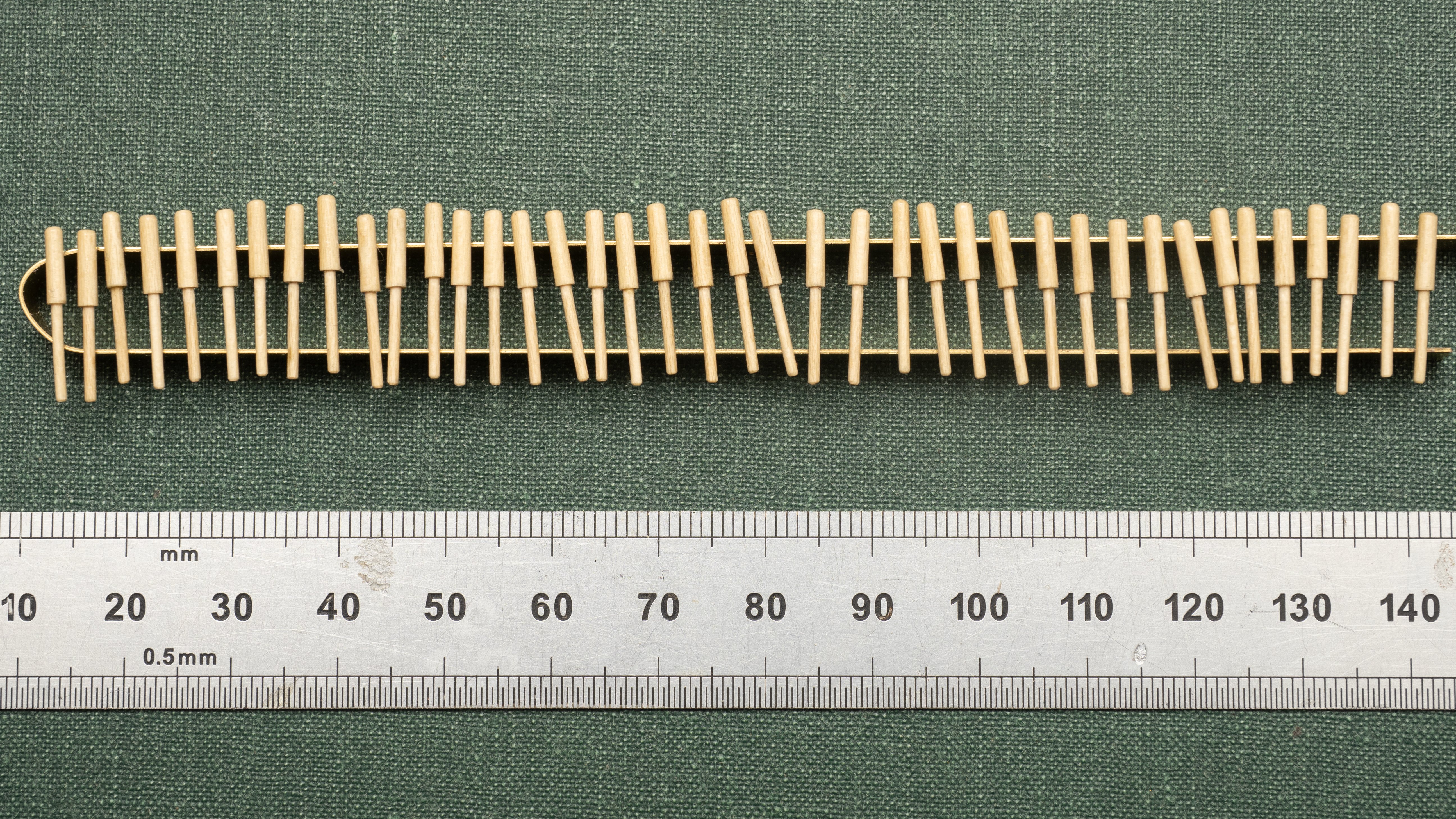
Here are 40 belaying pins on a rack drying after their second calt of varnish: And here are some of them mounted on the aftermost pinrails: It actually didnt take as long as I feared. An advantage of this method is that the tolerances are very tight. The lower part of each pin was a nice push fit in to the hole in the pinrail (all pulled through the same hole in the drawplate) and the upper part was all turned to the same dial settings on the lathe. The pins on Olympias are obviously a very simple shape, but the same method could be used to make shaped pins vers accurately using the stepped process described above for the brail fairleads, mast head fittings etc. (I wouldnt like to try it as a scale much less thatn 1:24 though...)
- 319 replies
-
- 10
-

-
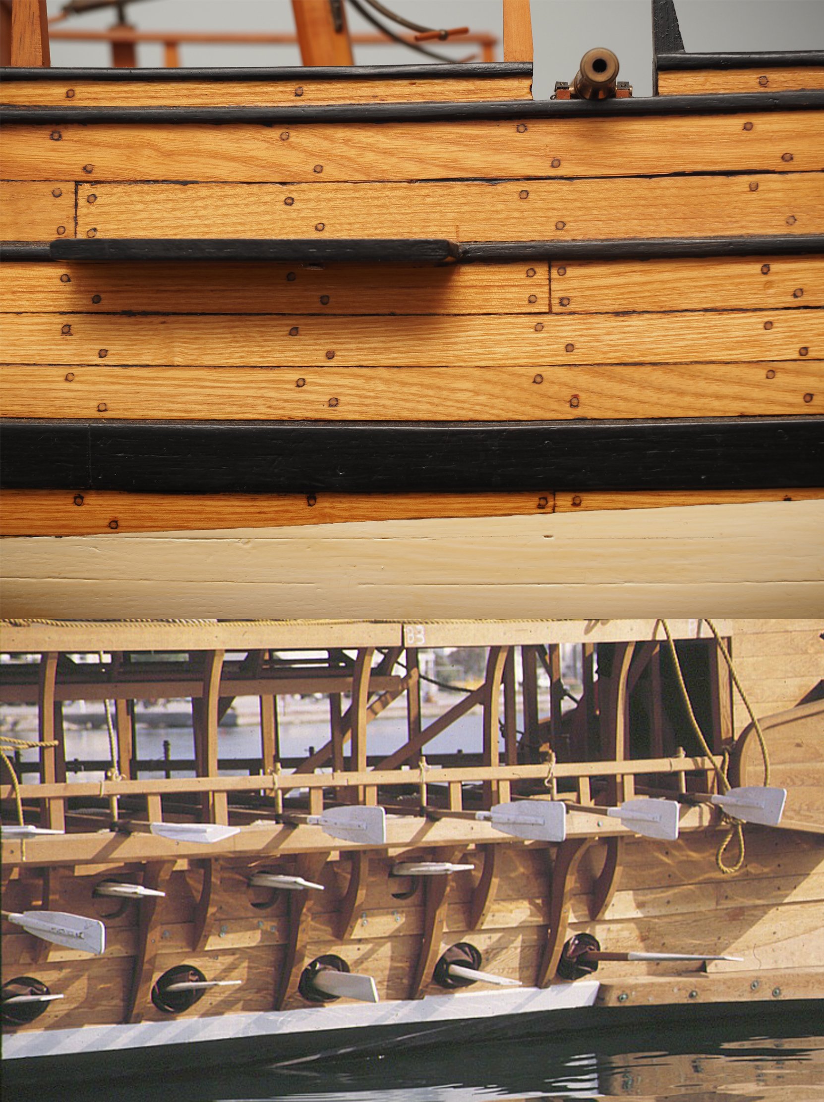
Now I’ve got a production line going, I’m finding my two-part method is going quite quickly (32 out of 40 made so far...) and seems to result in reasonable tolerances. Looking at photos I'm reasonably sure I’ve proportioned them right. The diameters of rope to belay on them varies between 14 and 24mm diameter full size and I’ve proportioned the pin to accommodate the largest rope. Here is a picture of a couple of pins on my rail with 0.8mm polyester rope belayed (equivalent to 20mm full size), alongside a photo of the one of the rails on the full size vessel. The mix of crisp polyester (the white rope in the foreground) and hairy hemp rope used on the full size vessel can be seen in this photograph. On the full size ship these pins were left unvarnished, but as Ive varnished everything, Ill probably varnish these as well. I guess I'm building a "Luxury yacht" version of Olympias, rather than trying to reproduce the, rather battered, post trials version! The lovely, sparklingly crisp, model polyester rope that I'm using from Rope of Scale fits nicely with this approach!

-
Been struggling today to work out a way to make belaying pins. The largest rope I will be belaying is 1 inch full size = 1mm at scale. So a 1mm diameter pin (1.5mm diameter handle) 16mm long, seems to make sense and matches pretty well with photographs of Olympias. Its a very simple wooden pin with straight sided handle (see image below). Tried turning these in one piece (from holly) but they kept becoming unstable and breaking as I tried to turn them in my Unimat. Same problem trying to turn them from brass, the overhang is just too long for the slender pin. Making them in two pieces as shown below seems to work. Process as follows: 1. Roughly 3mm round holly mounted in 3 jaw chuck and center drilled 1mm to a 5mm depth. 2. Swap the 1mm drill for 1mm brass rod and insert in hole to stabilise. 3. "Turn between centers" down to 1.5mm and cut off a 7mm length for the handle. 4. Cut a 1x1mm square section of holly and make into 1mm dowel through a draw plate (which for some reason - a long time ago- I made from a brass hinge...) 5. insert into hole in handle and cut off make a total of 16mm long for the pin. This length gives equall exposed pin above and below the pin rail (which is 2mm thick at model scale). Its going to be quite time consuming making all these pins (as always) but at least they dont keep on breaking...
-
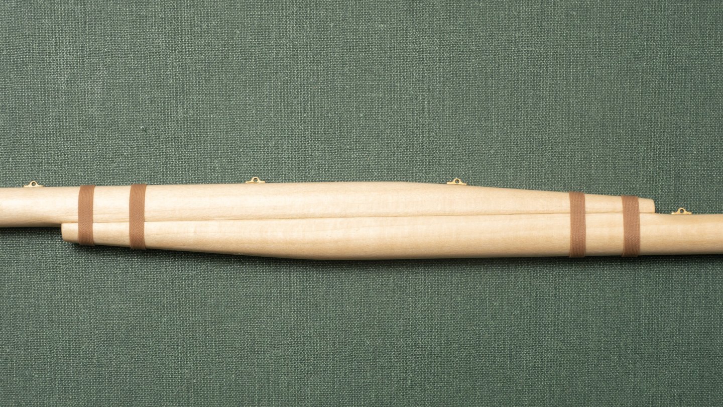
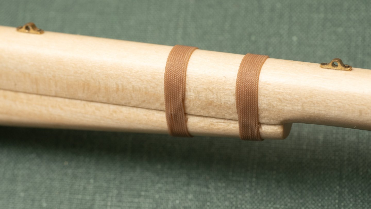
Completed lashings (using 0.35mm polyester rope) on my main yard, secured in place with a couple of drops of CA and overcoated with matt polyurethane varnish to hold them in place. The second image shows where the ends have been pulled underneath the lashings and trimmed.
-
Thanks Loie de Fly. Roberts (who was responsible for the rig design) does not talk about classical block/deadeye etc. design in the papers that he wrote for the Trireme Trust on the subject and seems to have used modern (19th century) versions that were readily available at the time. As far as I know, no Archaeological remains of Triremes have been recovered (they tended to float when "sunk"). However, some archelogical remains of merchant ships of the time have been excavated (which sunk due to their ballast/cargo and were preserved under the sea bed) and it would be interesting to see what fittings were recoverd from these. For this model I am (generally, although I havent been 100% consistent...) building a model of the reconstruction "Olympias" rather than attempting to build a model of an ancient greek Trireme, so I shall probably go for the modern style used on that vessel.
-
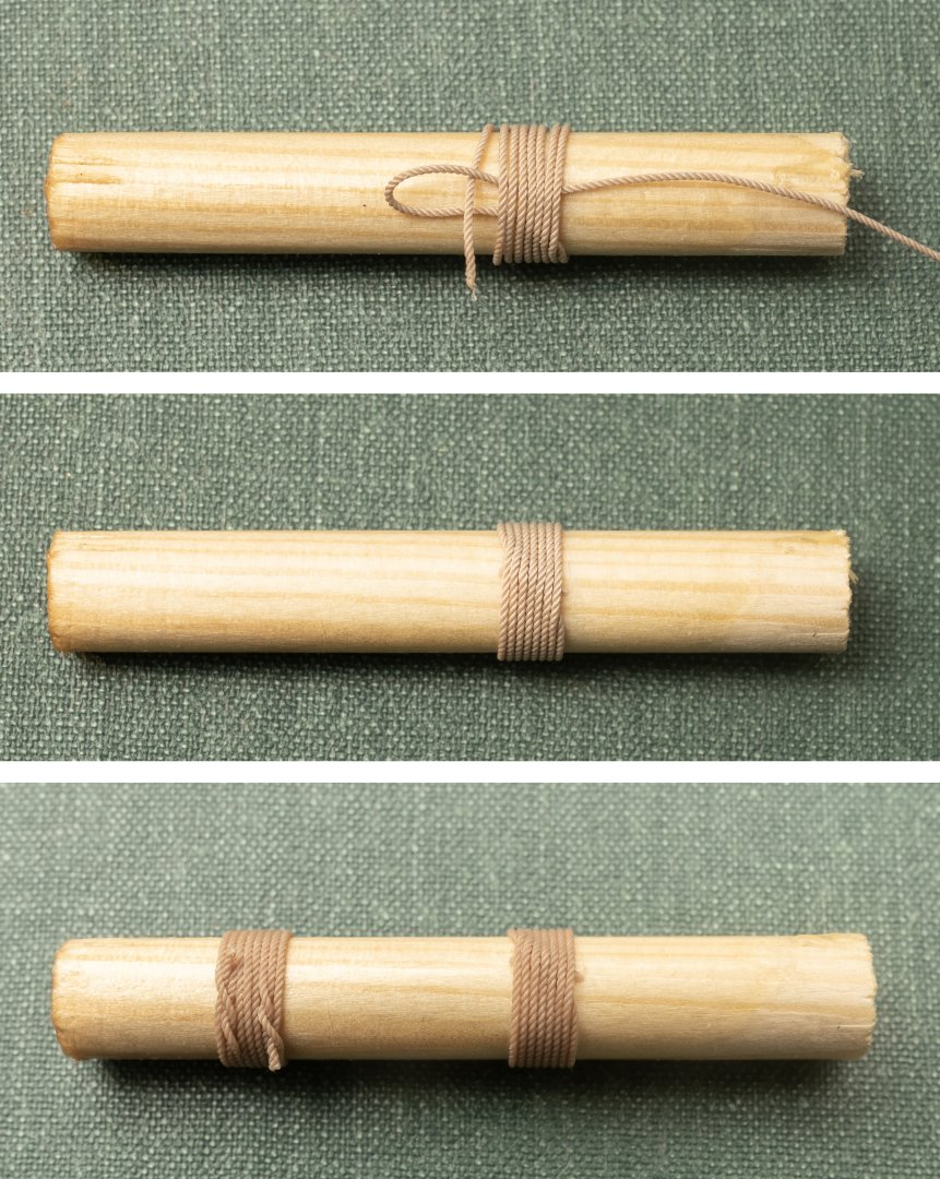
A fantastic model! Some really lovely work. Could you let me know what approach you used for lashing your yards. The main yard of my Trireme build is also made of two parts held together by (rather fewer) rope lashings. Ive tried out a couple of approaches on a piece of dowel to see what they looked like ("common whipping" and "round lashing" - image below). Neither seem quite right...
- 208 replies
-
- 2
-
-
- kitbashing
- Woodcarving
- (and 4 more)