
Richard Braithwaite
-
Posts
229 -
Joined
-
Last visited
Content Type
Profiles
Forums
Gallery
Events
Everything posted by Richard Braithwaite
-
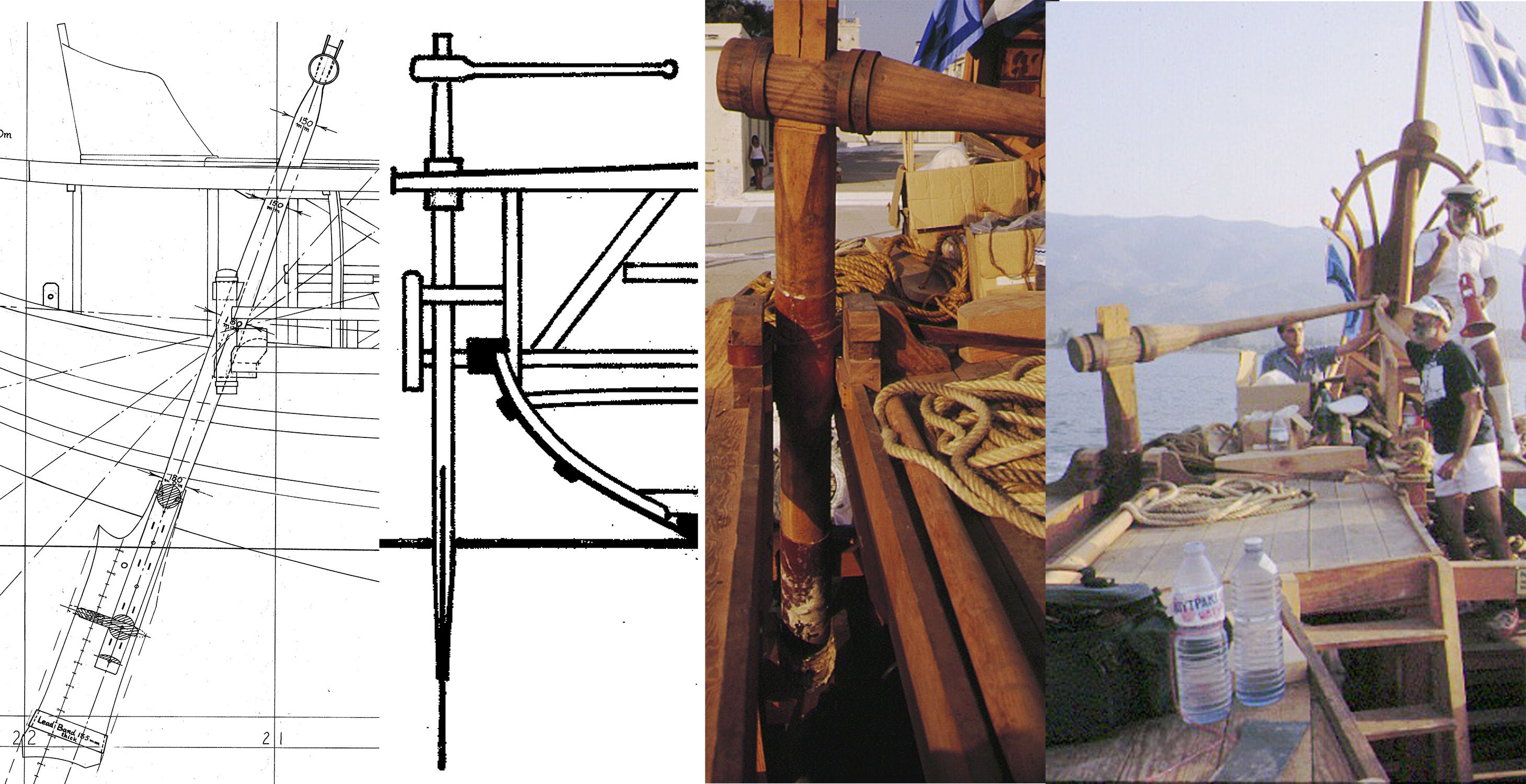
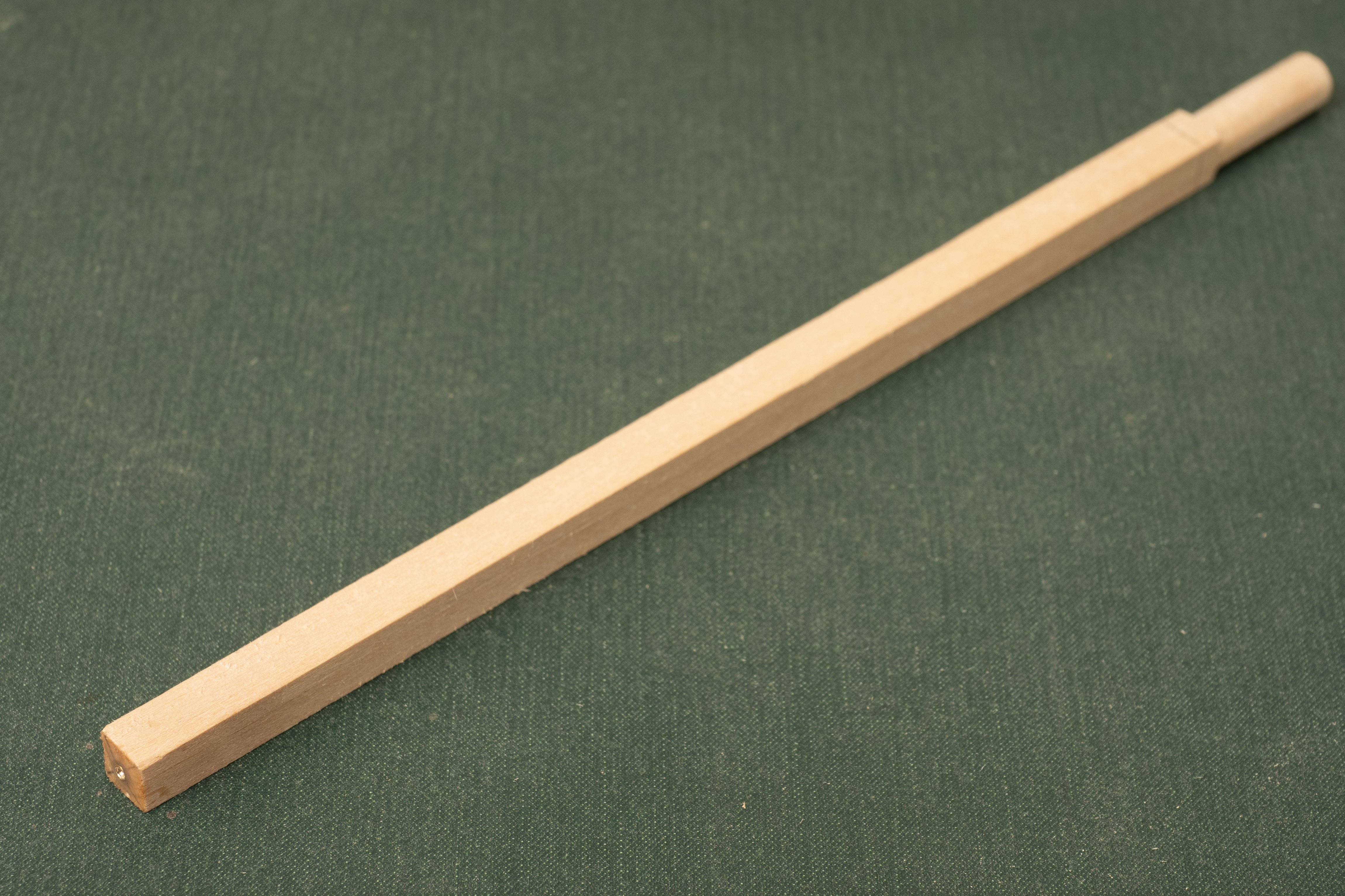
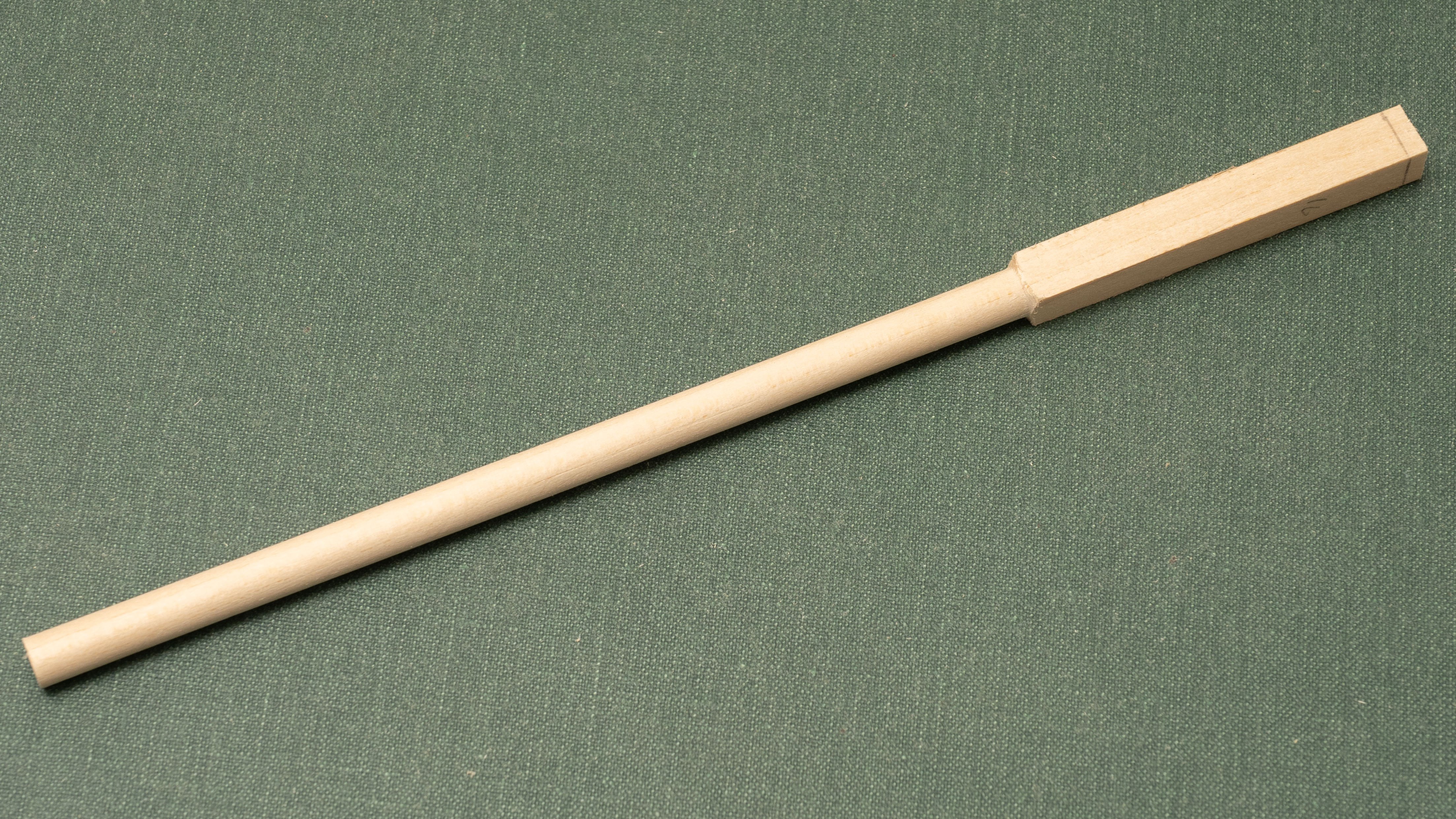
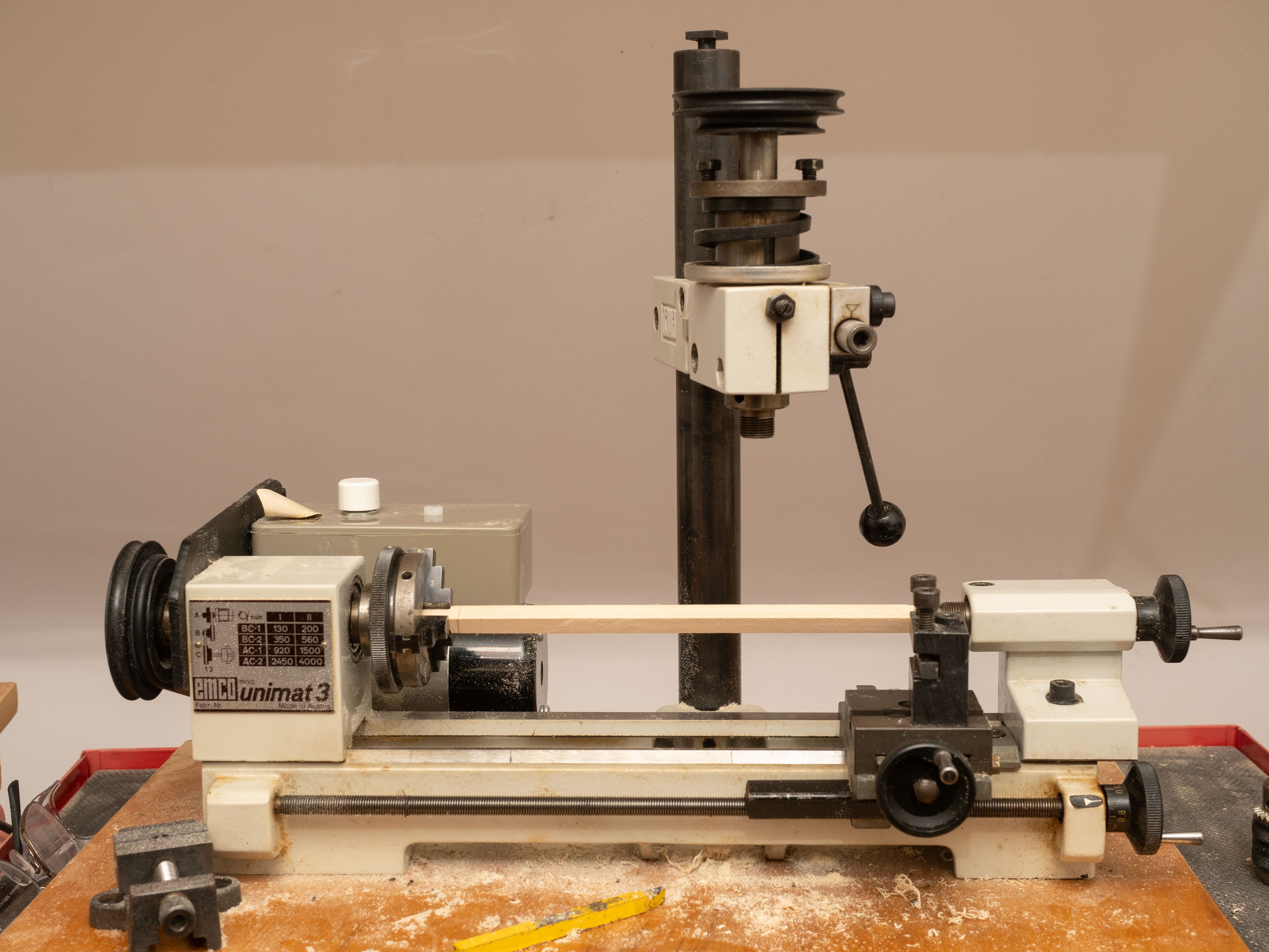
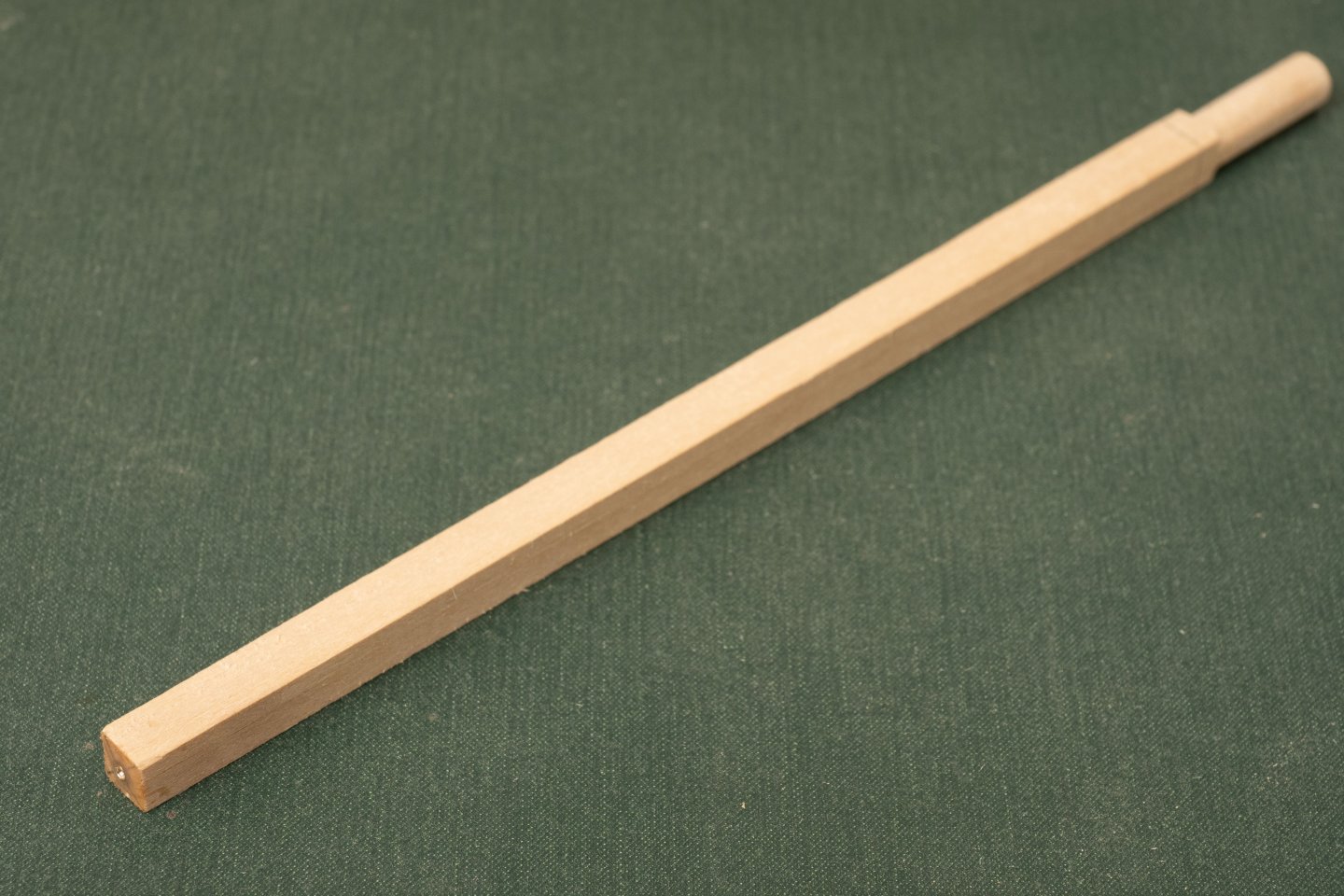
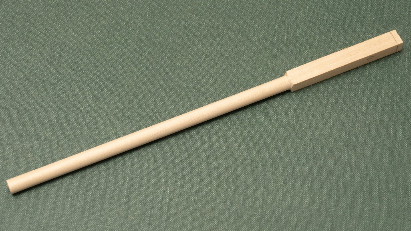
 The design of the steering oars is not particularly well defined by the drawing pack (at least the drawings which I have copies of…). The best information is probably on the Stern Profile and Plan drawing (Plan 12), although this only shows one view and does not define the geometry of the tillers. The general Arrangement Drawing (Plan 1) does show another view, in low resolution which does at least help the overall tiller dimensions. Taken together with images of the completed Olympias, these form a reasonable definition of the design for my model (extracts of Plans 1 and 12 © Estate of John F. Coates, reproduced with permission: The steering oar stocks were originally designed at a diameter of 150mm throughout and the design of the upper and lower bearings shown in Plan 24 sized for this diameter. John must have subsequently concluded that the bending stresses at the lower bearing would be too great and increased the diameter in this area to 180mm as shown in the extract of plan 12 above. The relevant parts of Plan 24 were redrawn to accommodate this increased diameter (Plan 24a). I built my rudder bearings to Plan 24 and so will be building my rudder stocks to a uniform 150mm diameter. It was a long time ago that I did this and Im not quite sure what my reasoning was… Ideally, I planned to build the model to reflect the build state of Olympias at her launch and original sea trials in 1988, but I must admit I have departed from that in some areas and built the model to reflect the design drawings (although even these contradict one another in some cases, as Ive discussed elsewhere in my build log…) Another post build addition that can be seen in the above photographs is the friction brake (wooden upstands with a leather strap attached to the rudder slot framing on the quarterdeck). Again, I dont have this in my model - at the moment... My lovely little Unimat 3 is just large enough for me to turn the stocks for the steering oars. Here is a blank (Lime wood as usual, but a bit denser than used for most of the hull structure) Ive roughly rounded one end, manually, to fit in my 3 jaw chuck and glued a 12BA brass nut in a recess in the other end to reinforce the center hole (first attempts, without this led to the center point tearing out…) Here is the blank in position in my Unimat. As you can see I’ve even had to overhang the center point holder on the right hand side somewhat to accommodate the length… Here is the blank turned down to 6mm diameter (150mm at full scale) with on end left square (and reduced in size using my Byrnes table saw – my other favorite tool in my workshop!) to accommodate the slot for the steering oar blade.
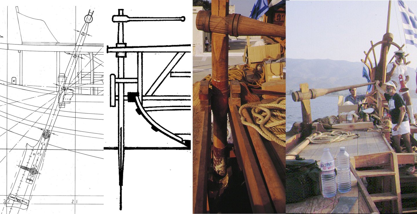

-
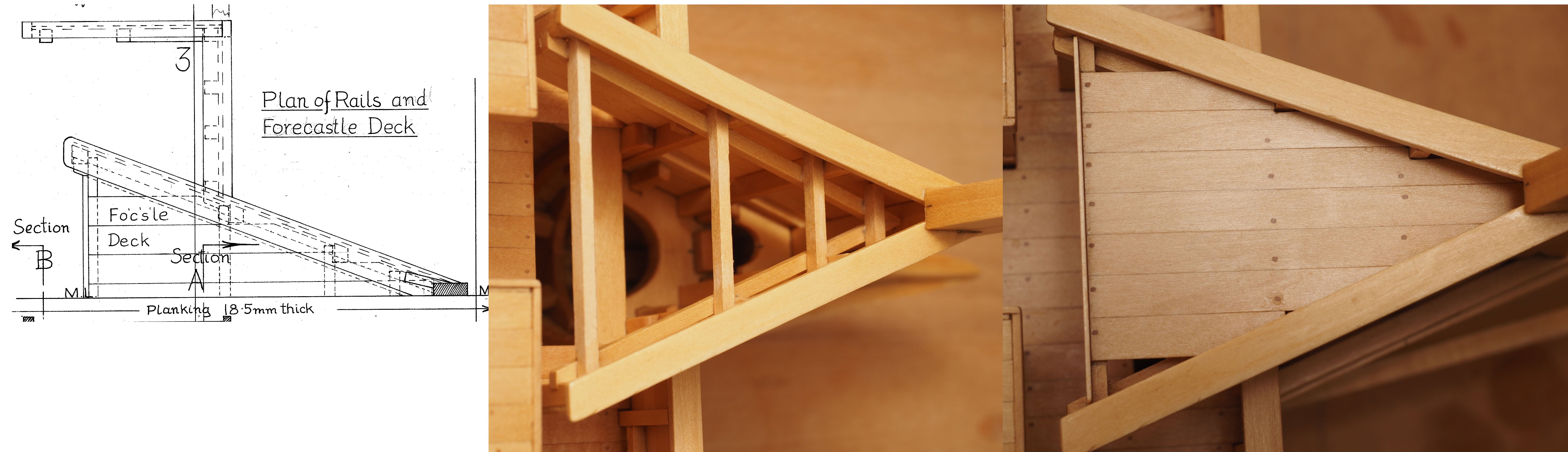
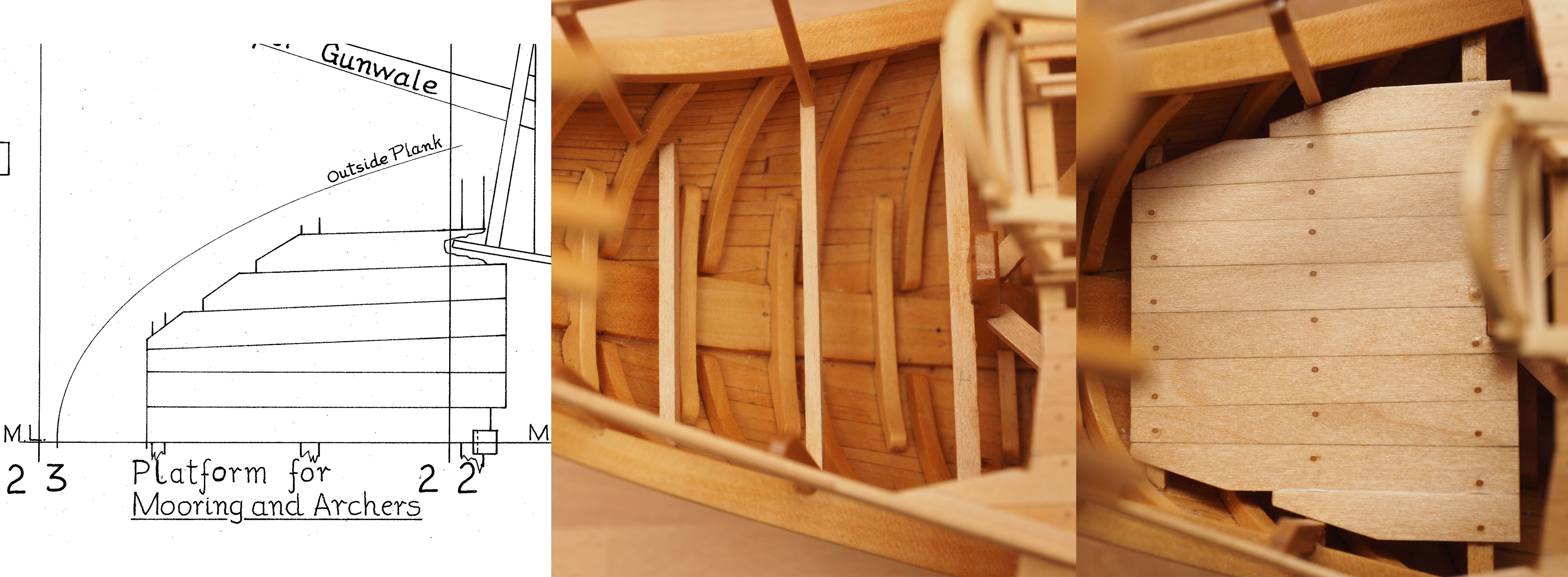
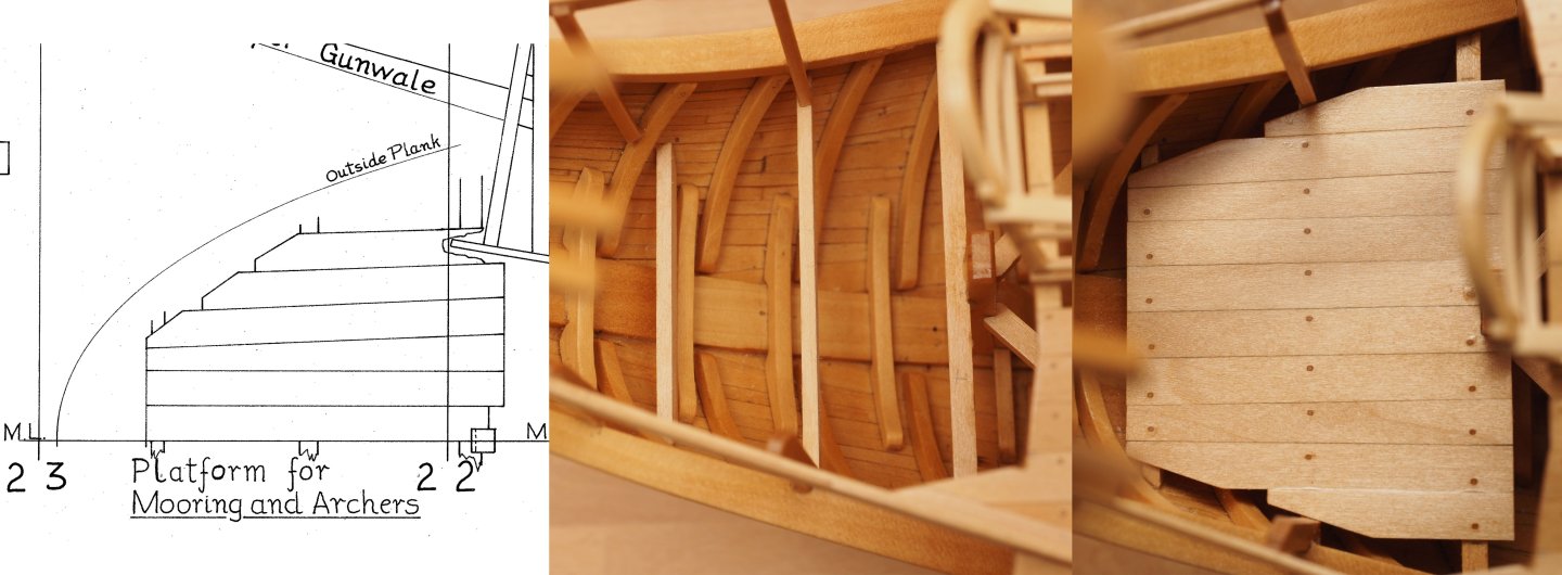
Left planking of the forward and aft platforms until after varnishing the main hull unit, in order to improve access (it was already difficult enough underneath the fixed quarterdeck structure...) Plan 21, an estract of which is shown below (© Estate of John F. Coates, reproduced with permission) shows the planking of the forecastle planking stopping short of the port and starboard extremities (I guess, because there is no beam for the forward edge of any plank to rest on...). As you can see in the image below, ive gone along with this despite the obvious hazard involved with getting a foot caught up in the gap if the ship rolls at the wrong moment... The aft moogin platform is shown in Plan 23 , an estract of which is shown below (© Estate of John F. Coates, reproduced with permission) together with my interpretation, which has ended up a bit wider at the aft end...

-
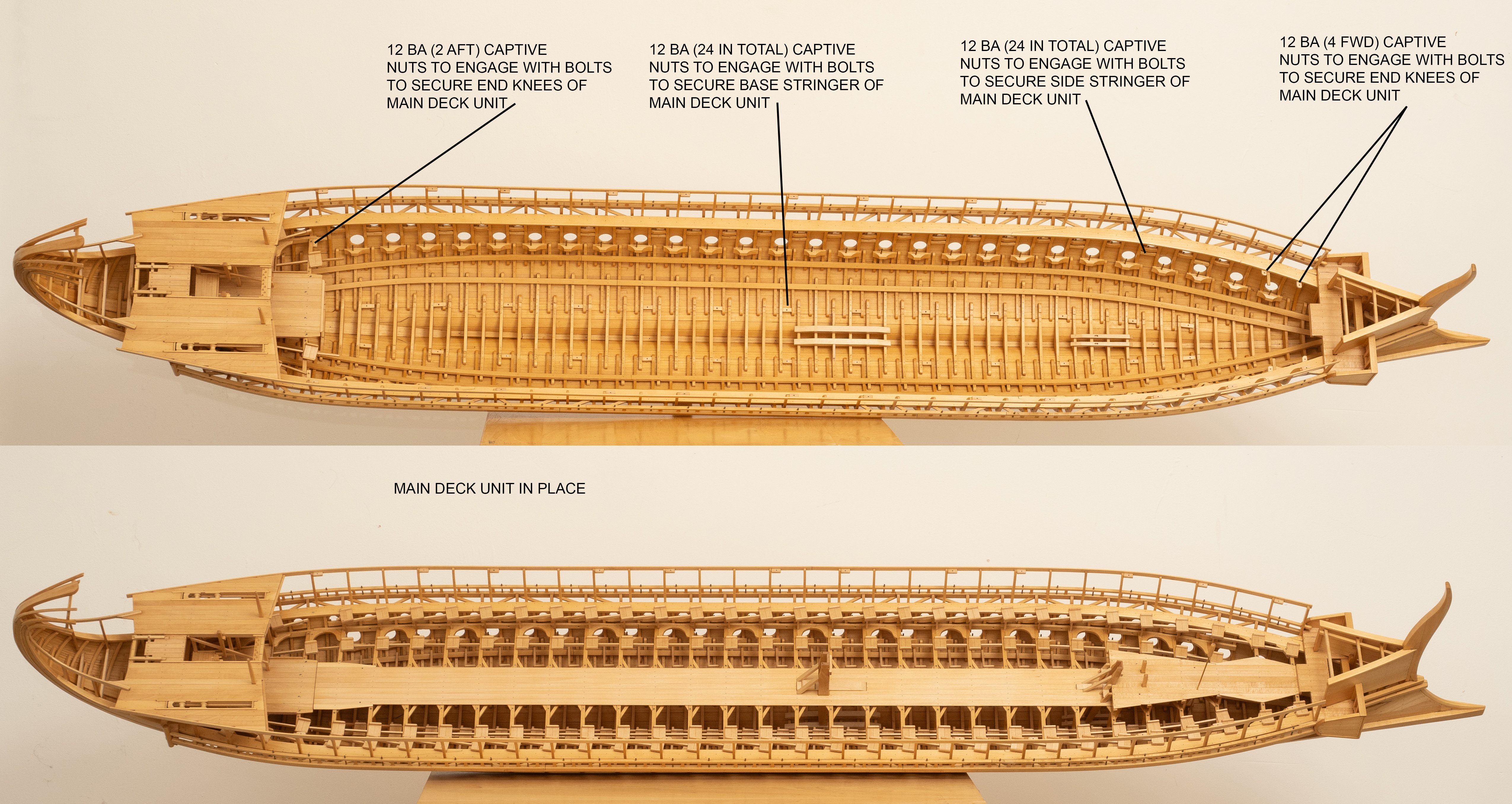
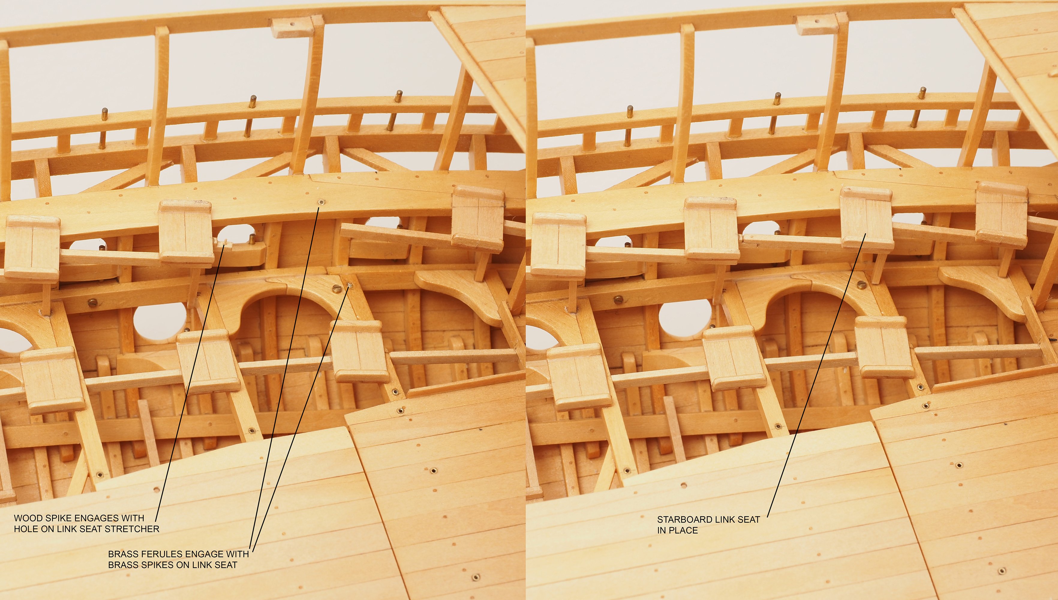
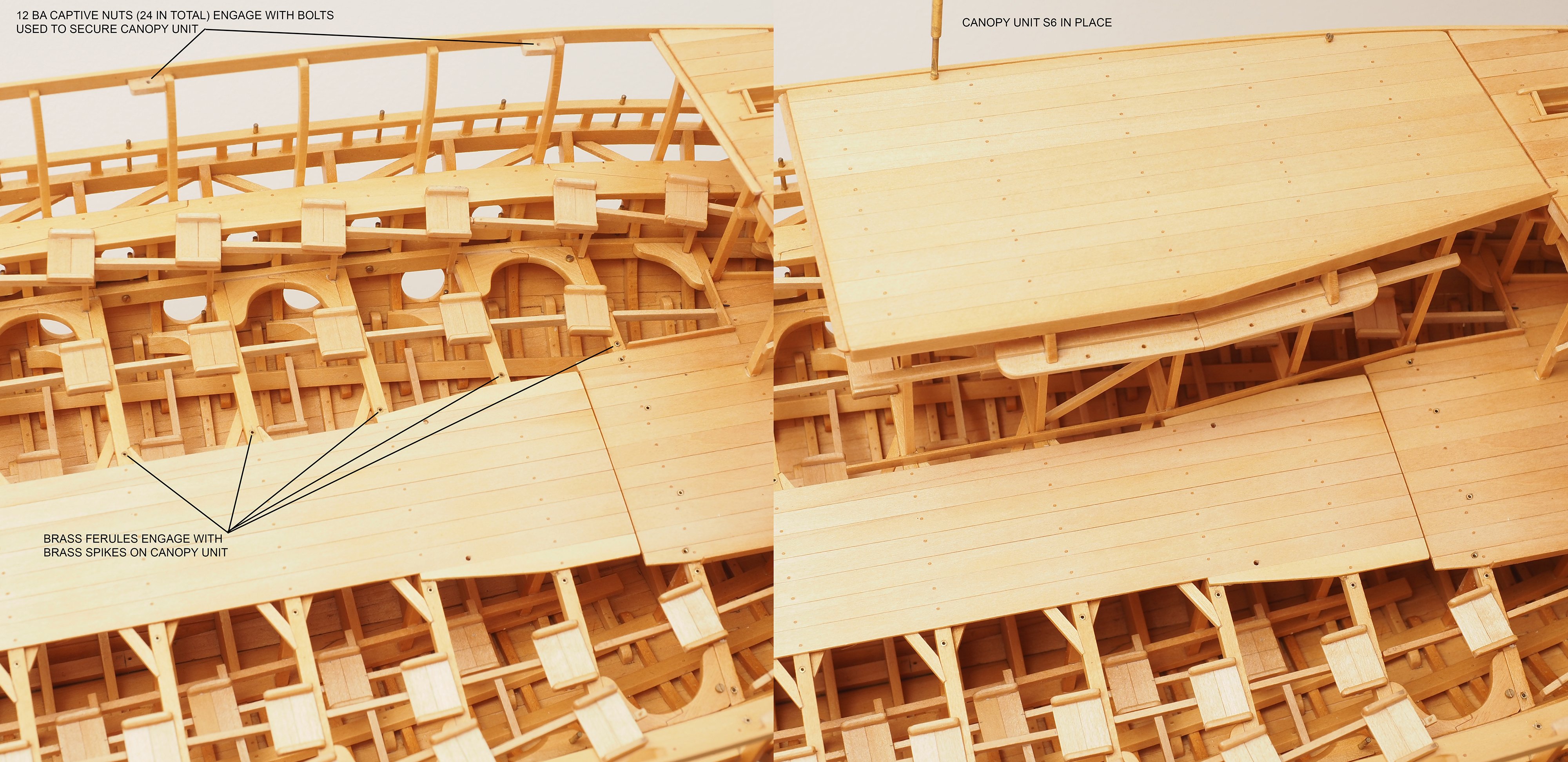
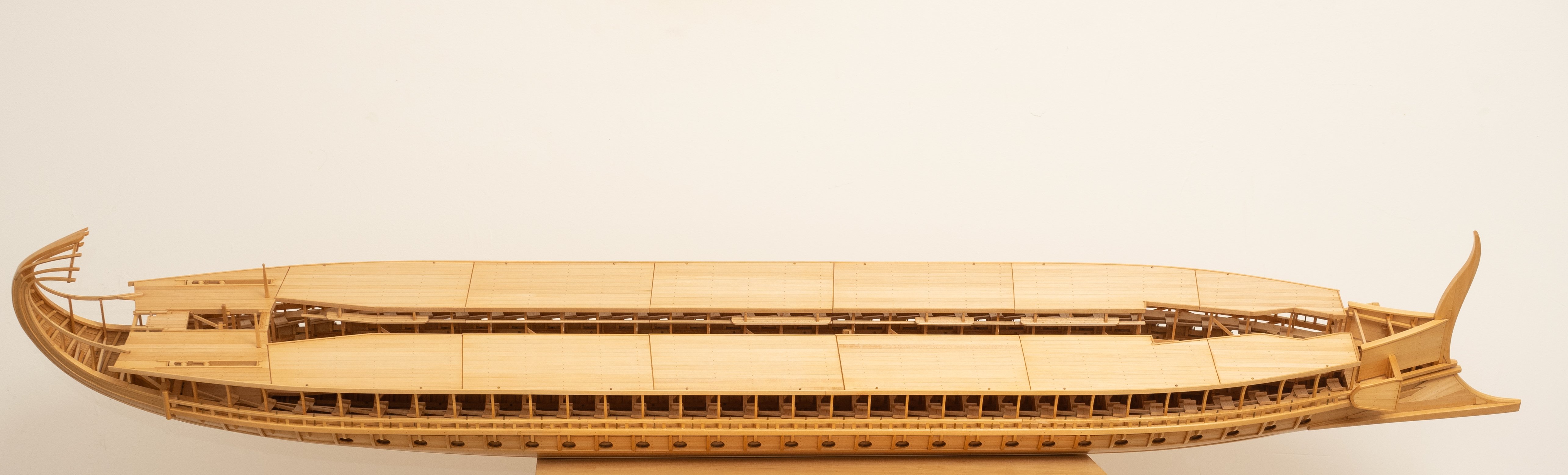
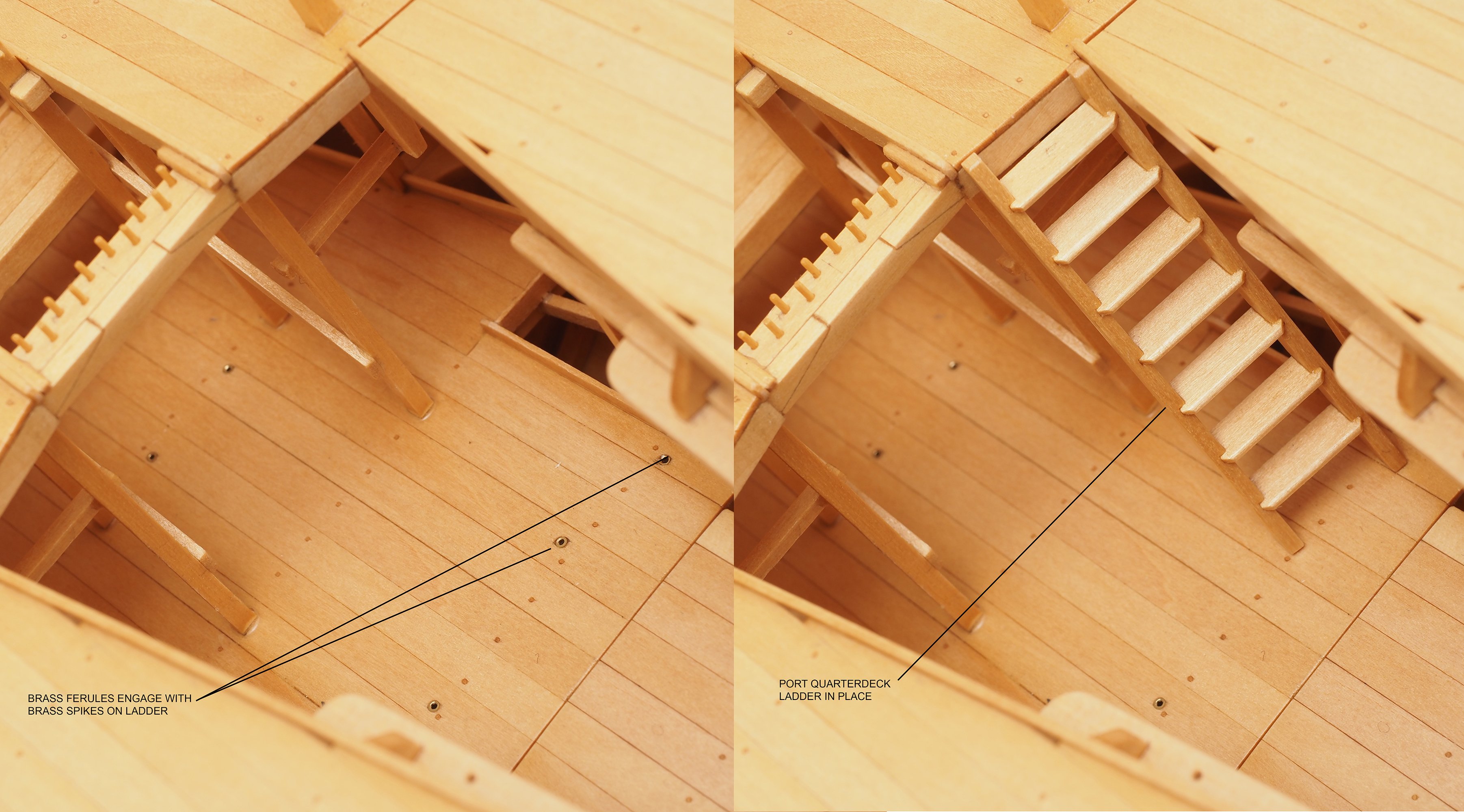
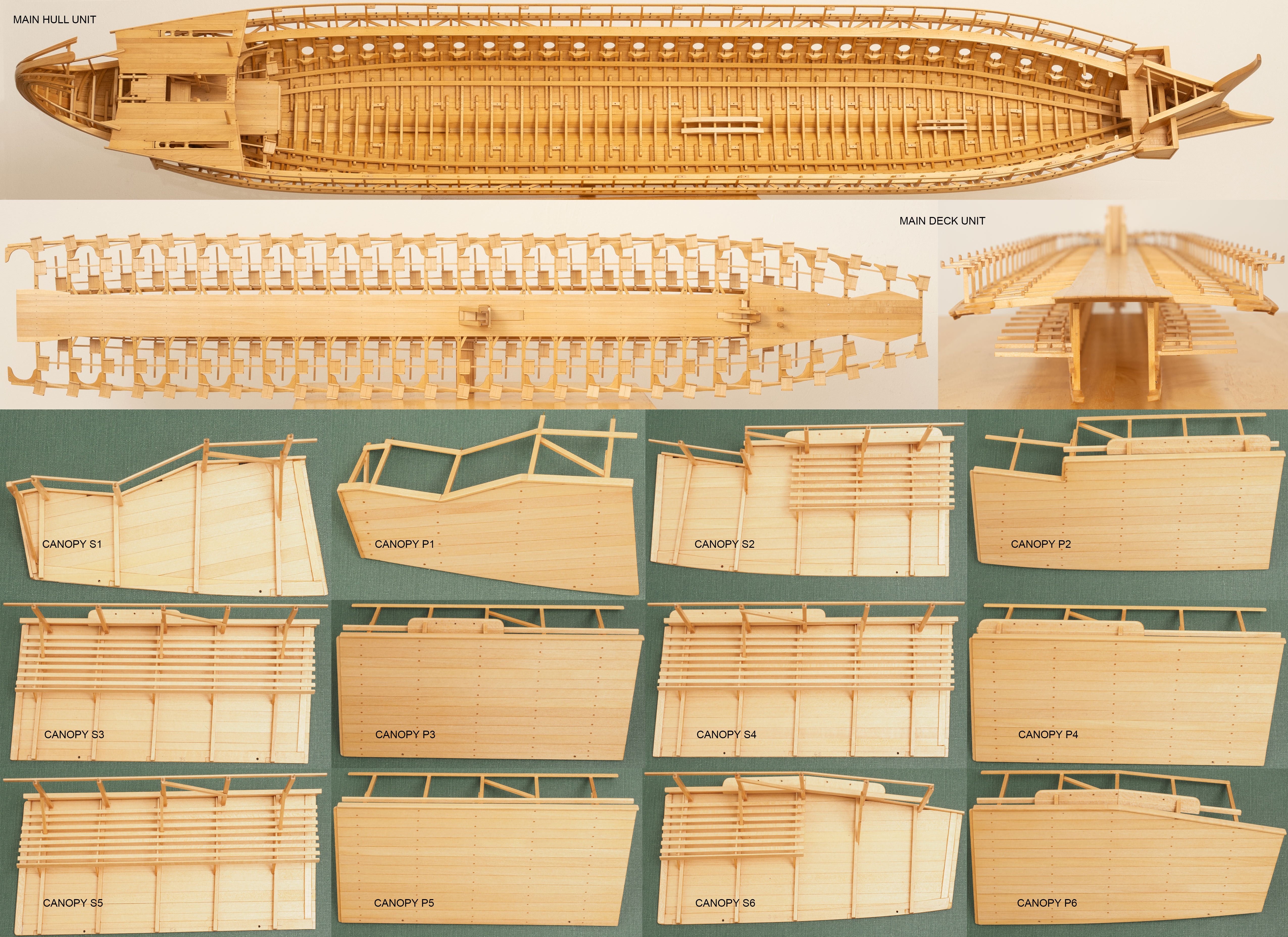
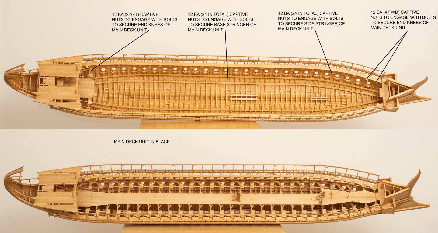
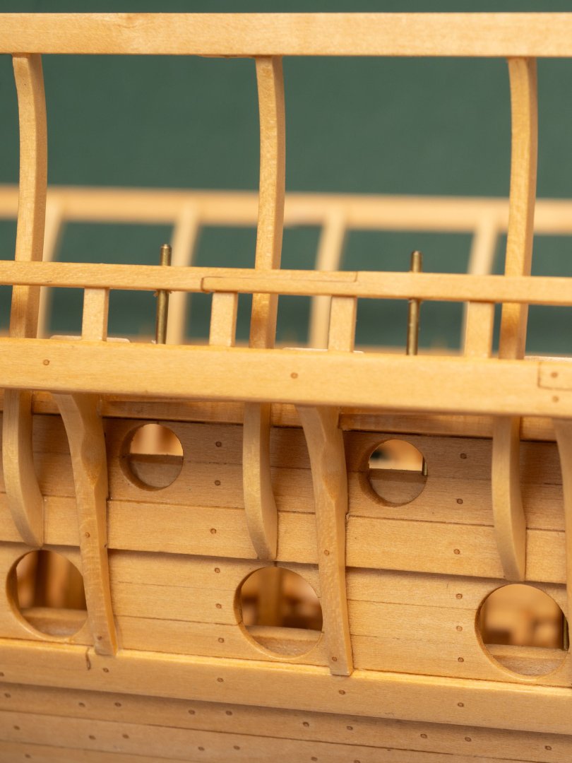
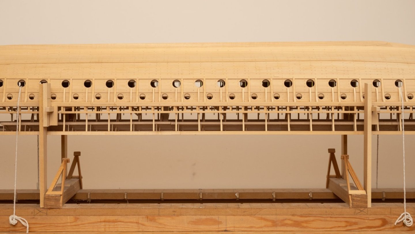
Putting it all back together: Som images showing how the main units go back together after varnishing. The main deck unit is placed inside the main hull unit and bolted together using a couple of brass screwdrives I made for the purpose (some of the bolts are quite fiddly to get at now all the seats are in place... The photo shows one of these screwdrivers accessing one of the difficult to get at bolts securing the base stringer. I made a couple of "Link Seats" to connect the thranite seats at the aft end of the main deck unit to the ones fixed under the quarterdeck: Then its a case of securing all 12 Canopy Units: The assembly with all main units in place: There are a number of other loose outfit fittings, like ladders to go in: Complete assembly takes me about 1 hour at this stage. Hopefully I wont need to take it appart again for some time...


- 319 replies
-
- 19
-

-

-
In my case Im building a model of a modern reconstruction of a Greek Trireme (Olympias) rather than a model of a Greek Trireme. Early photos of Olympias sugest it was coated with some sort of Yacht Varnish, which was probably Polyurethane.... But the main reason I used polyurethane was because Ive used it before and Im used to it...
-
Current stage of varnishing complete. Please to say, none of my fears materialised: 1. The older work didnt look any different from the fresh stuff. 2. I managed to avoid blocking up the threads of all the captive nuts 3. The lightweight structure didnt distort. Composite image of all the main components after sealing: As an aside Ive got myself a new umbrella reflector kit to use for flash photography. It came with 2 umbrellas. These photos were its first outing, so still getting used to it... Im alreadyquite pleased with the "soft" white one which seems to give quite an even illumination (when I point it in the right direction!) with nice soft shadows...

- 319 replies
-
- 13
-
-
-
Main hull unit and main deck unit now coated with 5 coats of Polyurethane Matt (thinned 25% with White spirit) and Ive started the first coat on the deck canopy units, ladders and other misc bits and pieces. It took me four full days to sand where I could (600 grit) before I started and 7 full days to apply the 5 coats to the 2 main units with a brush (sanding between coats with 1500 grit paper). Very fiddly work, there are a lot of brackets, stanchions etc that are quite difficult to brush around - even with the model fully dissasembled. I could probably have done it quicker with an airbrush, but dont have much experience using them so went for the brush in the end. I am quite pleased with the finish I achieved. Even the older wood (worked over 10 years ago) has some up nicely and is indestinguishable from the fresh wood (e.d. tabernacles and stowage racks). I was really relieved to find I could fit the deck unit back inside the hull unit (after varnishing) and bolt it down with out any difficulty. I had managed to keep the threads of the captive nuts free of varnish and there was very little distortion of the two units from varnish absorbtion (the hull had opened up about 2mm - which I was easily able to pull back with the bolts to the beam shelf on the deck unit. Hopefully the canopy sections (even lighter built - and so even more sensitive to distortion) will behave as well. Photo below shows how the wood like looks now...
-
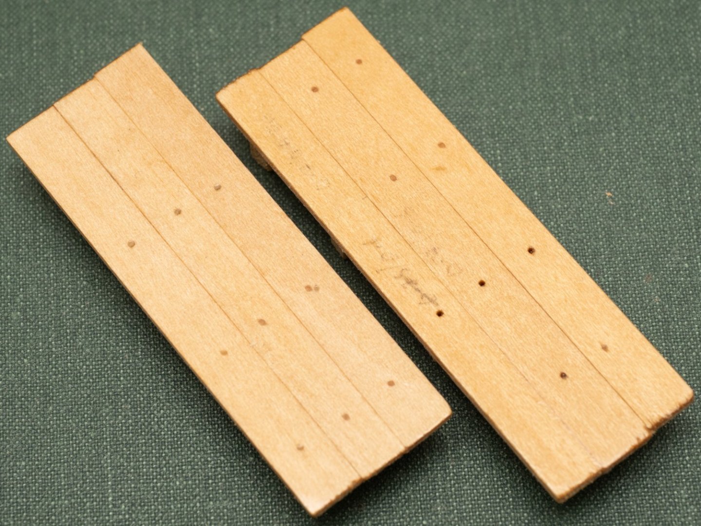
I am managing to sand most of the planked surfaces down to reasonably fresh wood, but there are some areas I wont be able to get at (eg. Internal hull planking between stifeners) and other areas that are made of such slender wood that to sand them risks damaging them (e.g. internal stanchions and rowers outfit). In order to see how much difference this would make to the varnished apearance I made up the test pieces (below) from some panking panels I made about 5 years ago to try out different trenails/ hole dimensions. 1. The one on the left was sanded down to "fresh" wood (350 grit followed by 600 grit) then cleaned with white spirit and coated with 5 coats of Ronseal, Ultra Tough Mattcoat Clear Varnish (polyurethene) - 1st coat thinned 50% with white spirit. 2. The one on the right was not sanded at all. Simply cleaned with white spirit and varnished. I was surprized at how little difference there was between the 5 year old and fresh surfaces (there are some pencil marks on the right hand panel which make it look a bit worse...). Im hoping that the difference wont be that noticable, particularly as it will be on different pieces of wood and there is natural variation accross the wood used anyway... The picture below is of a model I varnished (again , matt polyurethane varnish) 35 years ago (!) The hull planking is ash and is has darkened slilghtly over the years to quite a pleasing colour. Hopefully this aging effect will help to iron out any differences in wood preparation on my trireme.

- 319 replies
-
- 10
-
-
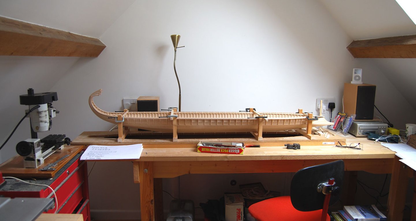
The fourth evolution of my build cradle... The upper works are very light which makes inverting the model interesting. Ive adapted my cradle so it supports the model inverted on two beams which pass from port to starboard beside the upper thole pins. This way the weight is taken on the lower outrigger which is supported by numerous brackts and so should be strong enough to take any forces I subject it to while sanding and varnishing the hull.
-
OLYMPIAS DRAWINGS AND TRIREME TRUST ARCHIVE I have recently been in email corespondence with the archivist at Wolfson college who is responsible for managing this archive (Jude Brimmer). The point of contact she has given me is https://www.wolfson.cam.ac.uk/library/archives/trireme-trust , which includes both links to the catalogue and their contact form. She has permission to provide is a PDF ‘research pack’ of a selection of the drawings which the estate has chosen as being particularly suitable for modelmakers. (GA2 and Plan nos 7, 8, 10 and 11). she has been authorised to provide this free of charge, on completion of a Copyright Declaration Form stating it will be used for research/private study purposes only.
-
Im running out of excuses not to seal/varnish this model... Once Ive finished the stowage racks I will have completed most of the fixed components on the hull and will probably embark on this phase. I havent done any varnishing of models for a long time (with the exception of my Manikins, who have been coated with polyurethane as they need some protection, given how much I put them to work around the building site...)and so am a little nervous . A few issues that I would welcome comment on: 1. Product: I am thinking polyurethane varnish (mat or satin?) both because it is waterproof and it has survived very well on models I built 40 years ago. 2. Condition of the wood: I have been building this model for a very long time, so some of the wood has been exposed to the elements for a long time. I have done my best to keep the model covered to avoid dust and have kept the wood as clean as possible. The wood all looks quite clean, but I suspect it will look different from "newly finished" wood when varnished. Some areas I can sand realtively easily, but other areas are not so easy. So Im still thinking about what preparation I do before I start. I have some old jigs I made earlier in the build so I can test finishes on these to see how the model might work out... 3. Brushes or airbrushes: Ive never used airbrushes so nervous of trying something new. The model does disassemble to a large extent (see image posted earlier in this blog), but their are areas of the hull that are difficult to get at. Thought it might be a way of getting varnish into some of these difficulat areas - but i have no experience of this. Also the airburshes look quite cumbersome and I think it migh be difficult to manoever them inside the hull? 4. Fixings: The model is assembled with a large number of bolts. I can remove the bolts prior to varnishing, but will need to protect the threads of the captive nuts from varnish. At the moment I am thinking of doing this with blobs of blue tack. Any ideas/comments on any of this most welcome.
-
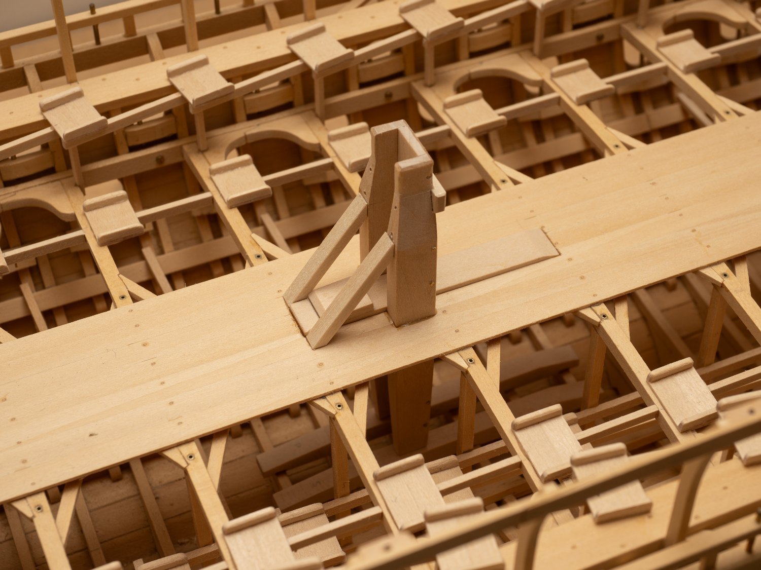
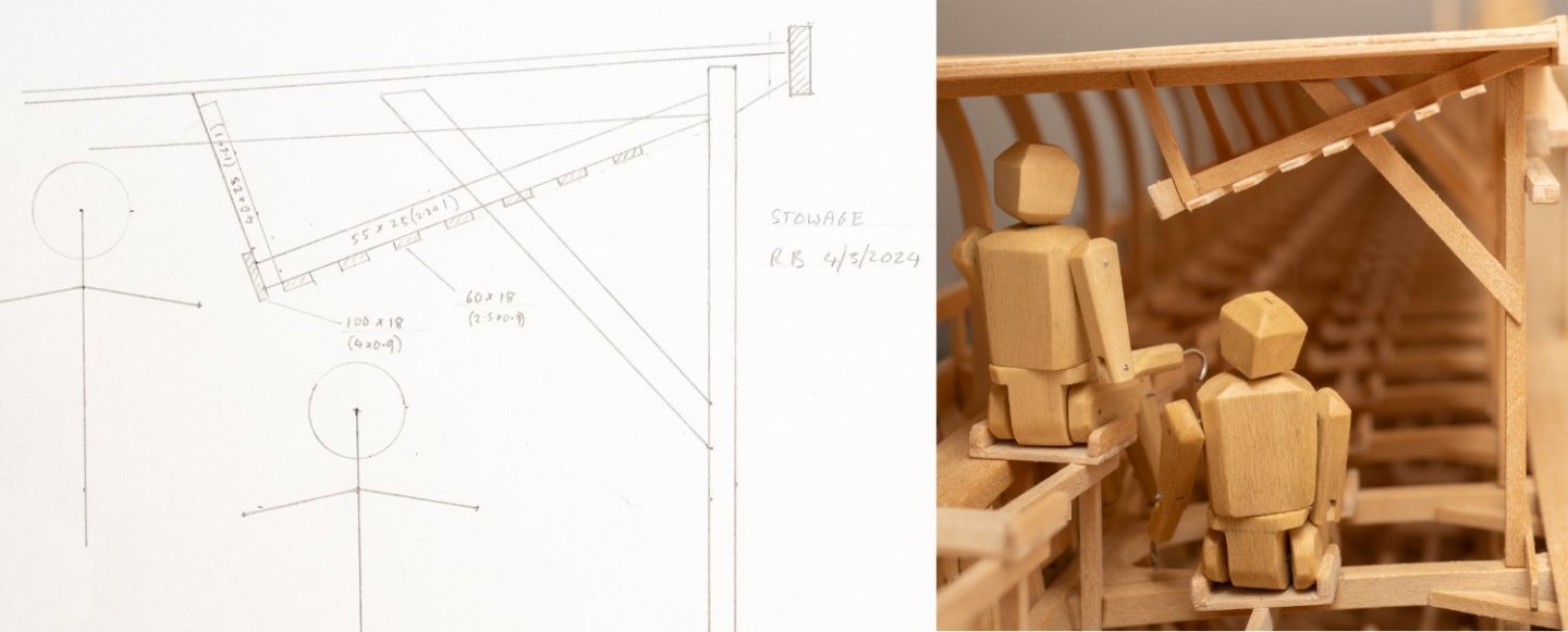
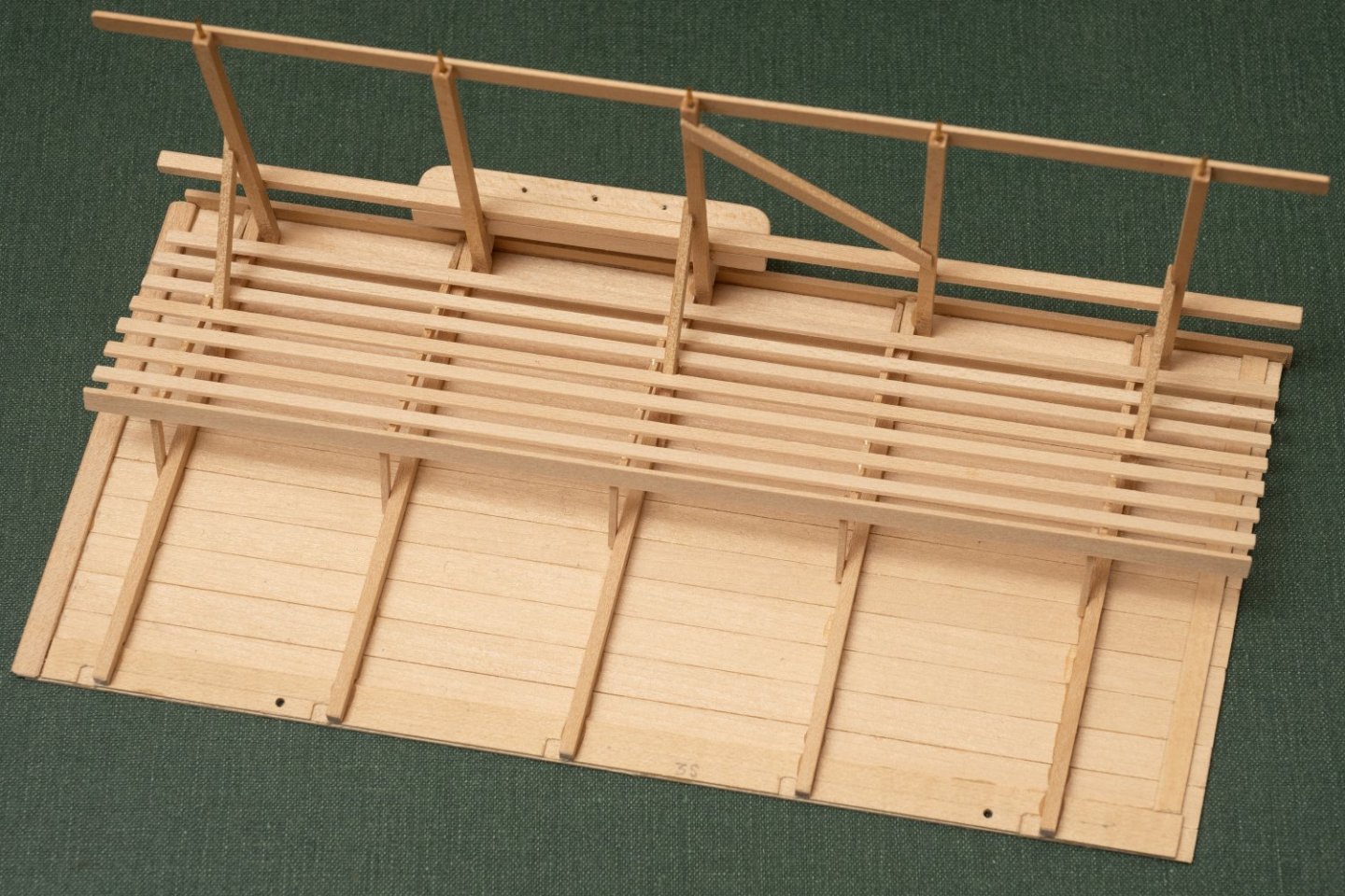
Olympias has very little in the way of amenities for its crew...However they did fit some stowage racks for gear underneath the canopy. The extent is roughly shown in the midship section drawing (John Coates Plan no.8) but no details or scantlings are given. My interpretation is taken from scaled measurements from images on line and stills from videos (the stick men shown in the sketch are traced from John Coates drawing and are rather taller than my Athenian marines - I guess he was checking clearances for the taller 1980's oarsmen...): And a view of the first canopy section fitted with a stowage rack removed from the model:
-
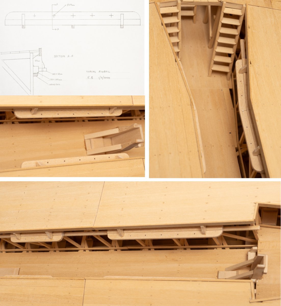
The belaying arrangement for the running rigging seems to have been developed during the build and trials of Olympias as the location of pinrails in photographs and videos of the vessel differ from their positions in the build drawings. Drawing MSR 11 (General Arrangement of Standing and Running Rigging) shows two pairs of pin rails (P&S) at the aft end and forward end of the gangway. their height is given quite low to the deck. Photographs of the copleted ship show 4 pairs of pinrails in total placed on top of the handrail. Ive done my best to scale these from stills taken from online videos (again, I really do (/should have!) need to visit the ship in Athens at some point...). My interpretation below:

-
Yes, on Olympias the mast is lashed to at the top part of the tabernacle, where it narrows. Its shown on the extract of Johns drawing I included in my post on Sunday.
-
Ive got one of these to make...I was thinking of making from brass sheet and chemically coloring, but 3D printed and then painted looks much easier, and probably closer in apearance to a casting...
- 536 replies
-
- 3
-
-
- Quadrireme
- radio
- (and 1 more)
-
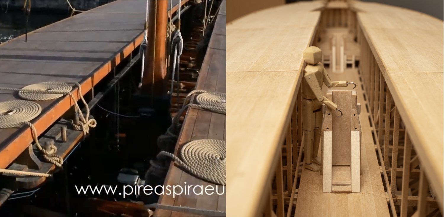
Limited access past the main tabernacle (with the canopy sections back in place) illustrated by one of my trusty marines, alongside an image of the full size Olympias. Interestingly, John Coates drawing shows a canted canopy support (see post above) which might have improved access somewhat. However, it apears from images of the actual ship that this was not done. My model has all canopy support stanchions vertical in line with what I can establish from images of the actual ship and the midship section and forward and aft arrangement drawings (I must get round to visiting myself one day...). Another difference from the drawings is that the handrail has been fitted much higher on the actual ship and serves as a foundation for a number of pinrails. I cant find any drawing of the pinrail arrangement, but I think I can come up with something fairly accurate by scaling from screenshots of the video below. The image above was taken from a still extracted from this video:

-
By the way, and slightly off topic. I was very sad to hear about the death of James Byrnes, the man who built the fantastic table saw that enables me to machine wood to a stunning level of accuracy. He also made a rather lovely rope making machine as well as sanders and thicknessers, which would have been lovely to posess! Link to his site with an obituary. Byrnes Model Machines Home Page
-
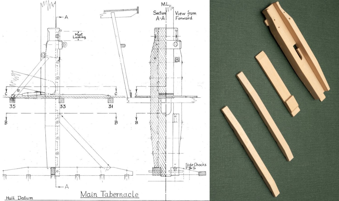
Work proceeding on the main tabernacle. Slighly messy hole for the lower rigging eye on the starboard side of the tabernacle. Despite setting it all up (I thought accurately) on my Unimat, I drilled the hole in the wrong place. The repair involved gluing in a dowel and redrilling....At the moment you can see the remains of the dowel, but that should be covered by the rigging eye when I fit it. I always reassure myself, when I end up doing these bodges/repairs, that this sort of thing occurs in full size ship and boat building all the time. On one memorable project I was involved with a fitter cut a large hole in a main structural composite beam on a high speed vessel. The repair was complex and involved detailed liason with the customer for approval (as it was a lightweight composite structure). Some days after we did the repair the fitter returned and cut the hole again... so we were then in to an even more complex repair of the repair. Another reminder to check drawings before you cut...but we never do do we? Extract of Drawing MSR 12 © Estate of John F. Coates, reproduced with permission.
-
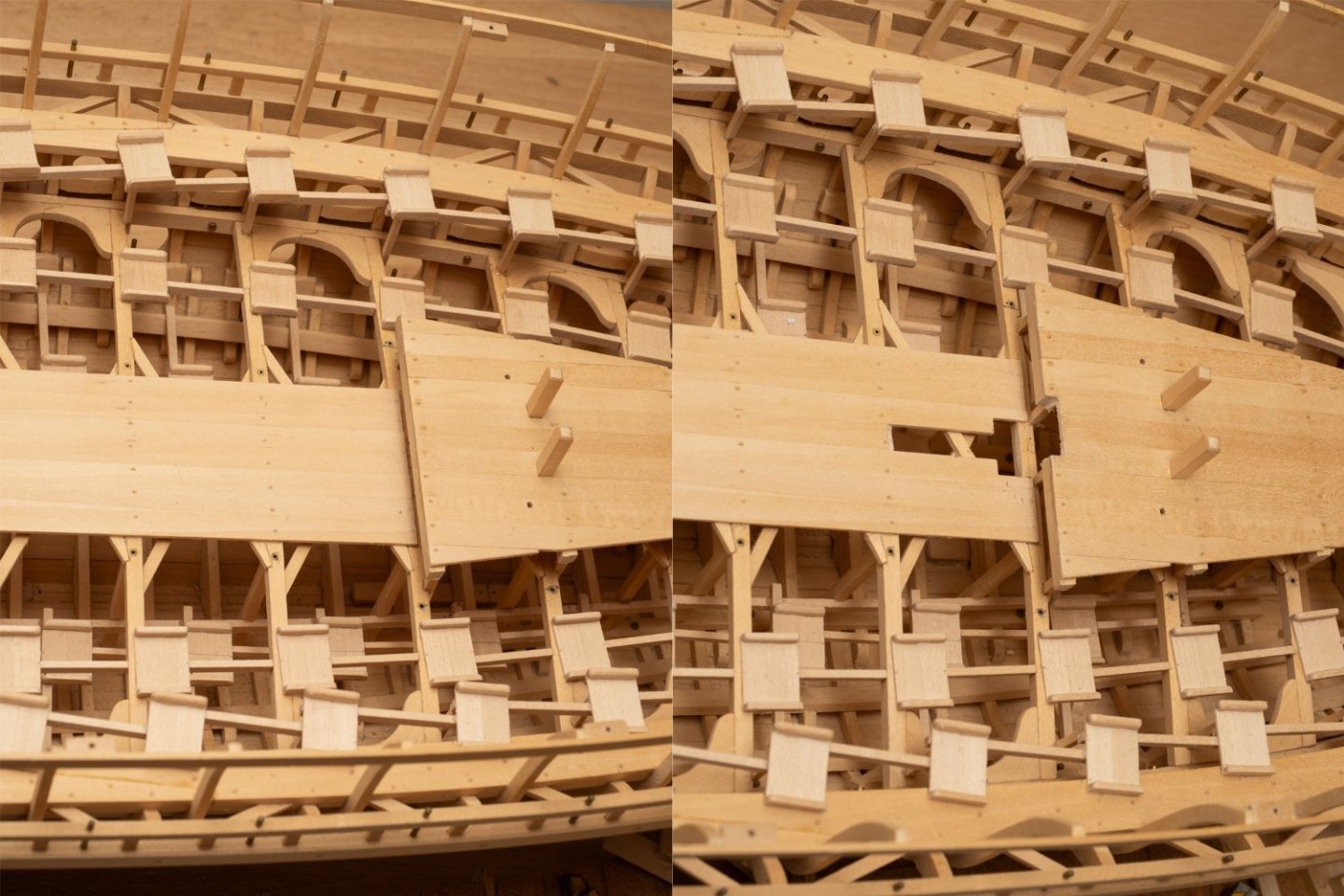
Another example of poor planning... The tabernacle for the main mast is much larger than that for the foremast. So when I make the cutout in the deck for it I also have to cut through the diagonal bracing pieces between teh deck beams. I probably wouldnt have fitted these, had I thought about it. However, they are shown on the midship section drawing (which includes these frames), so I guess John Coates didnt think about it when he did that drawing either! Just shows how important it is to review the complete drawing pack as you make a model (or build a ship) as there are bound to be inconsistencies...

-
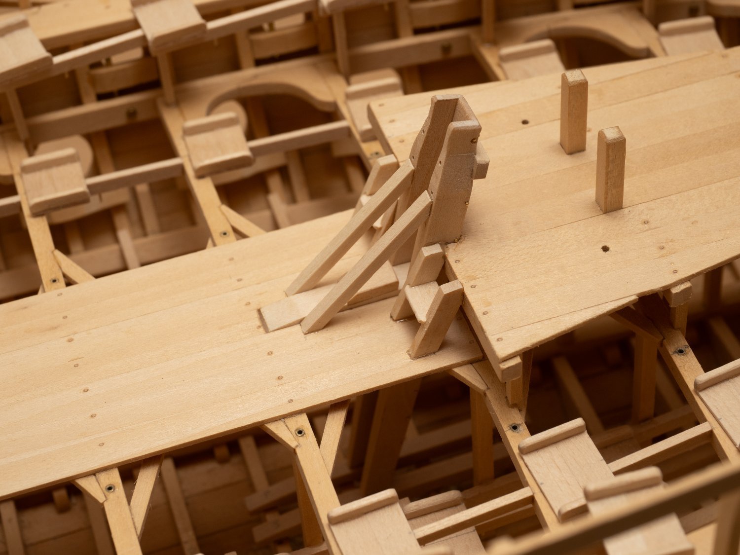
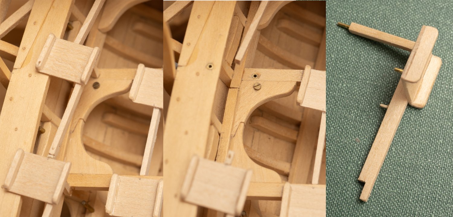
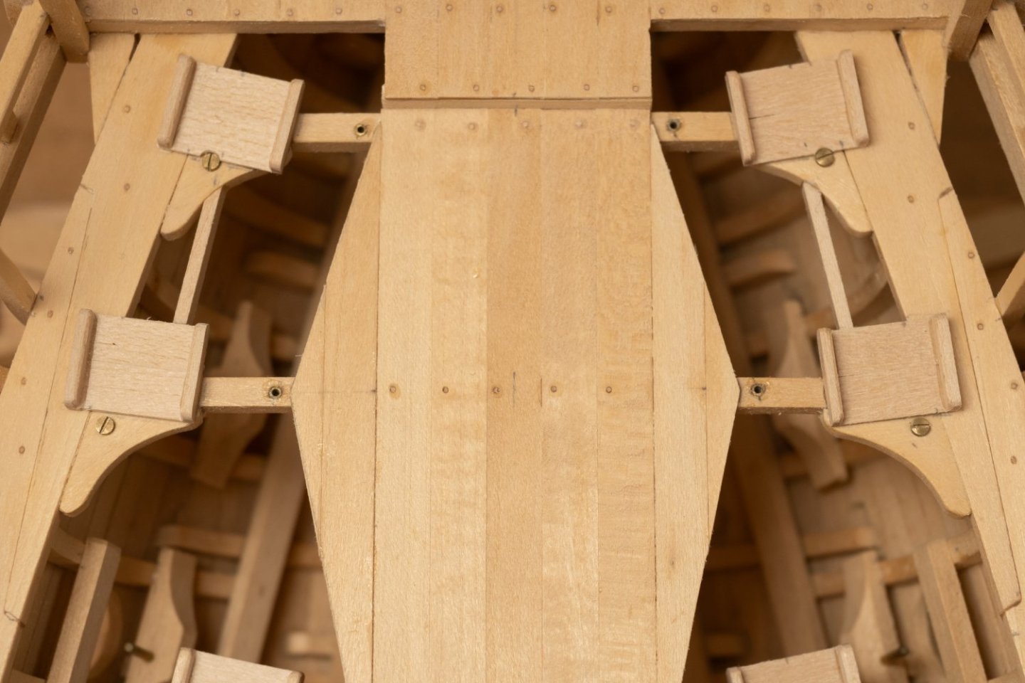
So Im fitting the lower seatings for the tabernacle "remotely" through the deck beams onto the floors. They are both in place with the taberbnacle to ensure proper alignment. The piece of wood lying longitudinally on top of the floor and in between the seatings is intended to help align them fore and aft (the center line drawn on this timber lines up with a centerline mark on one of the floors). The starboard seating has been glued in place in the photo. Hopefully the port one will be easier with the starboard one in place to act as a guide. Not the way I would have chosen to do this if I had planned it all properly. Lowering the starboard seat through the deck beams and into place, after I had applied glue relied on the steadiness of my hands rather more than I usually like to!

-
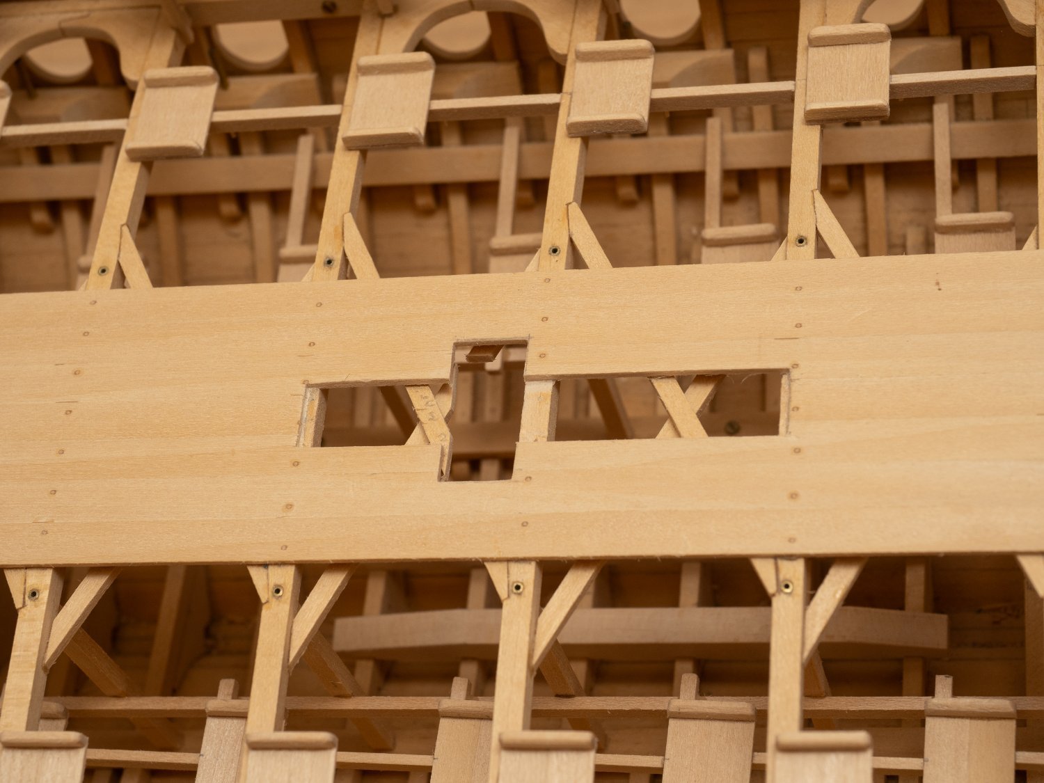
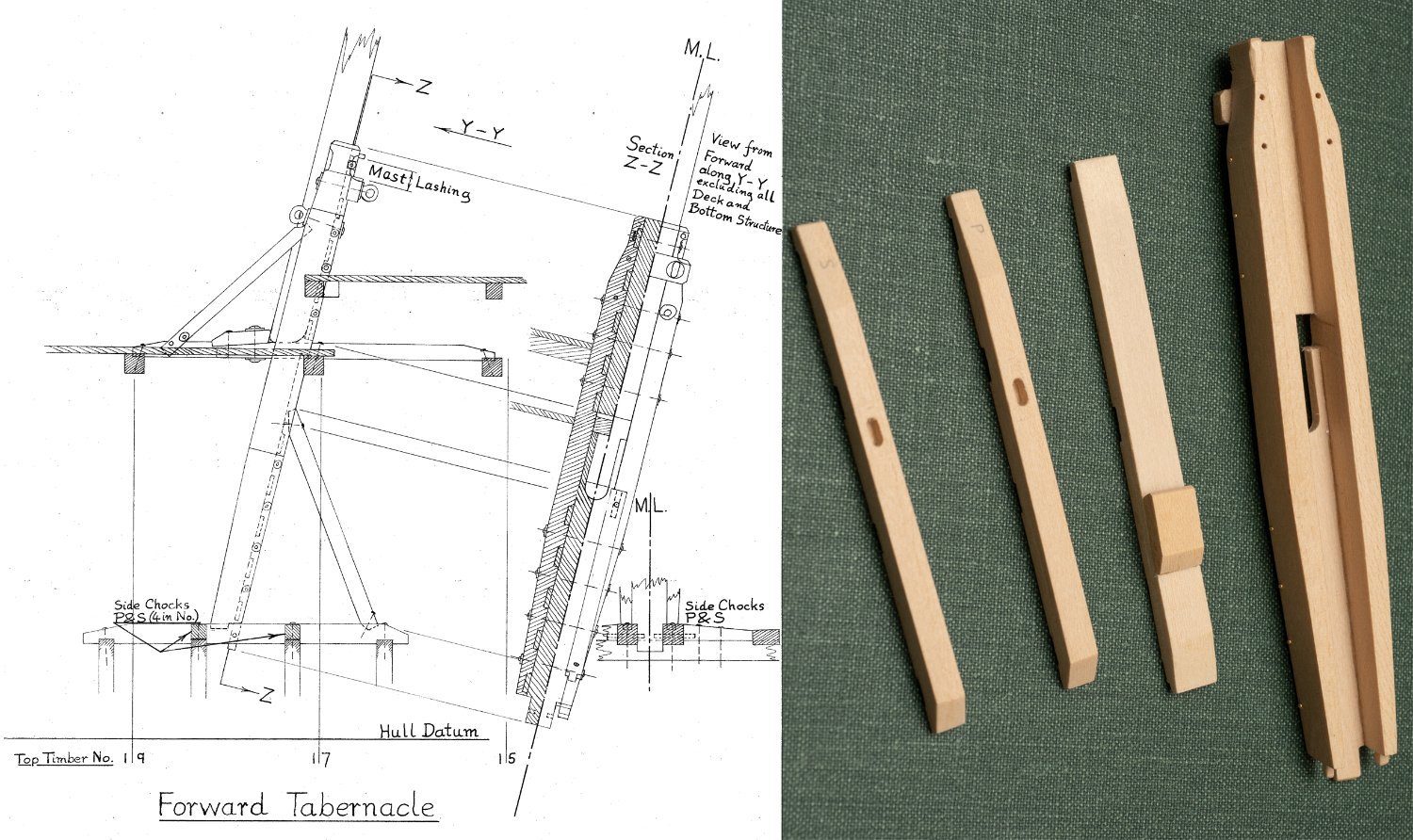
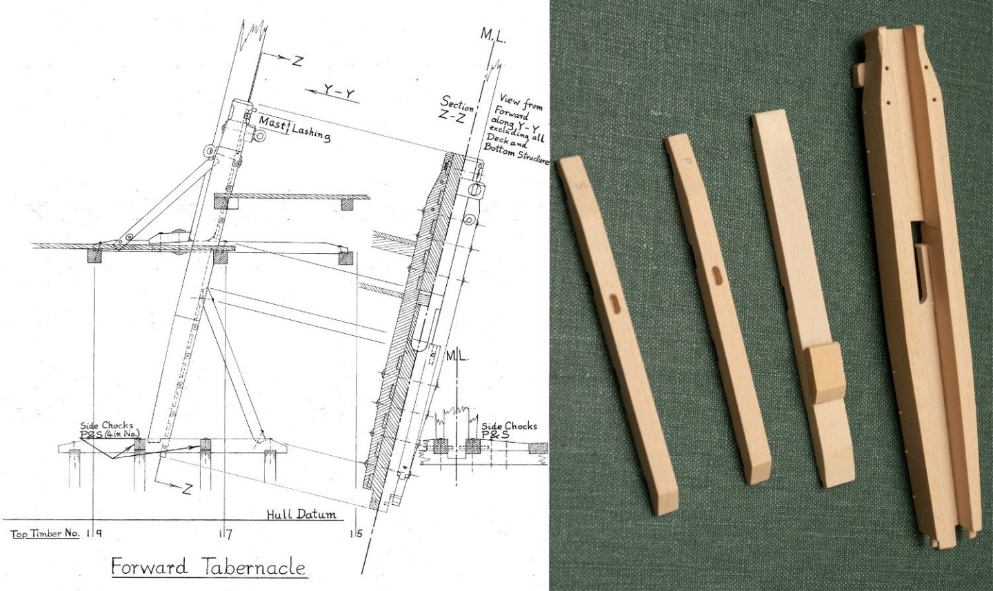
Havent posted for some time... Have been ploughing on with the top level seats, which are now finished. Usually enjoy the therapeutic nature of repetetive tasks, but must admit that 170 seats... Anyway, now putting in tabernacles for masts. Would have been easier to install before planking the gangway, but I am where I am... I took a bit of time to work out how these are constructed from John's drawing (MSR 12 © Estate of John F. Coates, reproduced with permission) and some, not very clear, photographs of Olympias. The main components of the forward tabernacle are shown below: And the hole I have had to cut in the gangway to install it: I was originally thinking I would remove the whole deck assembly (un boltable) to install the lower seating for the tablernacle, but Im now thinking that it will be more accurately alighned if I do it with the deck bolted in place. Just a bit fiddly fitting the timbers through all those beams and seats...
- 319 replies
-
- 12
-
-
-
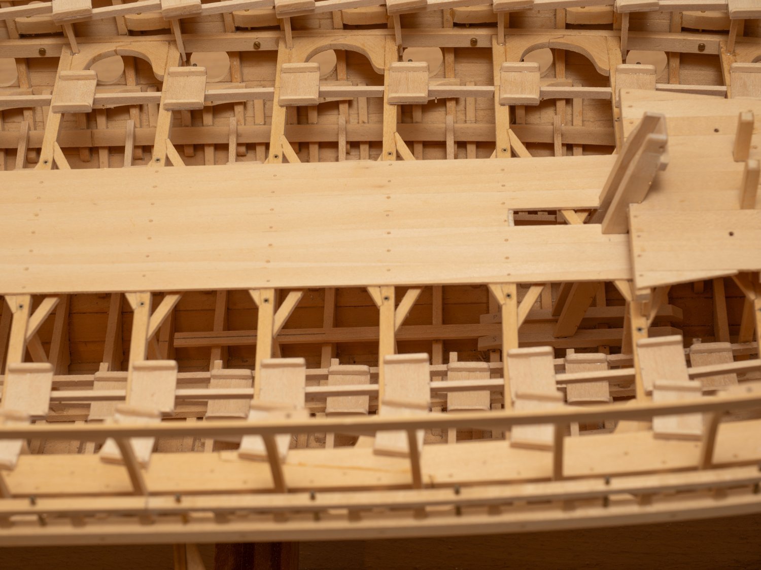
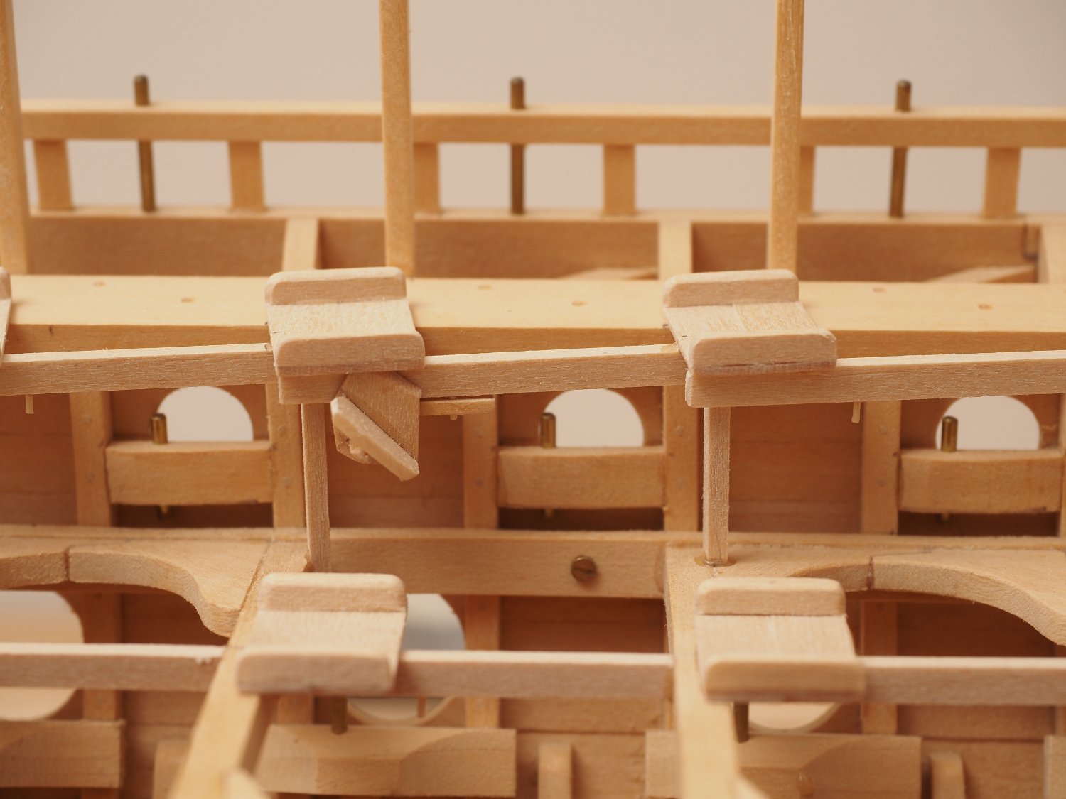
Simpler at the fore end where the forward most seats on the upper level sit on the removable section. Luckily the bolts that I put in this area cleared them (well almost...). At one point I wasn't planning to fit seats so these bolts were placed without thinking about them...
- 319 replies
-
- 15
-
-
-
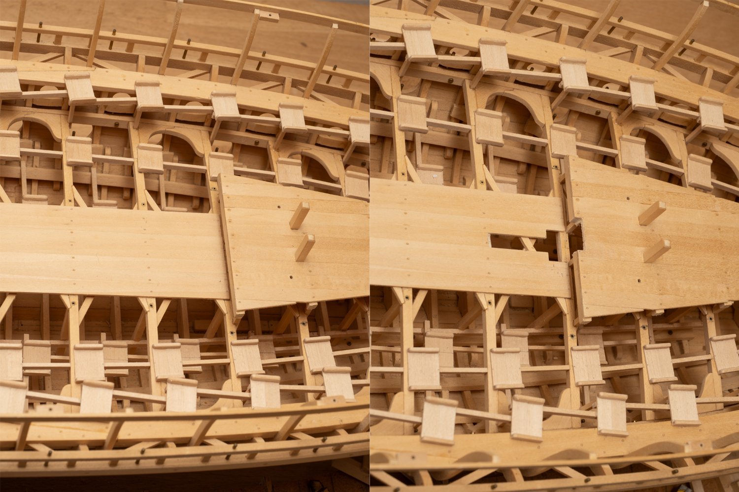
Still plodding away with the seats. The series of photos below shows my solution for a removable seat to allow for the removal of the gangway section of the model.