DavidEN
-
Posts
136 -
Joined
-
Last visited
Content Type
Profiles
Forums
Gallery
Events
Everything posted by DavidEN
-
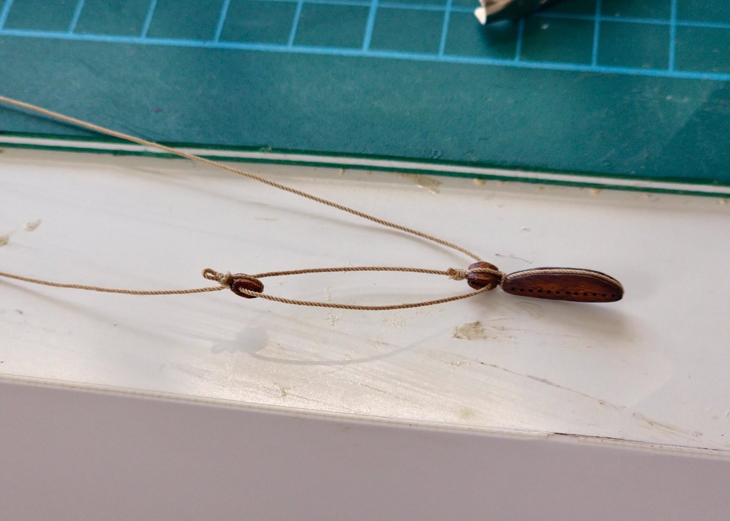
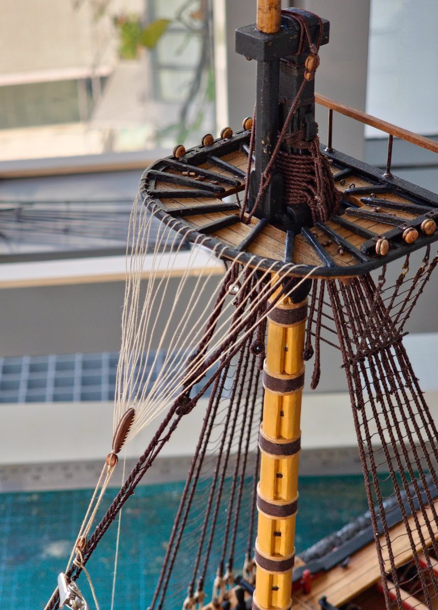
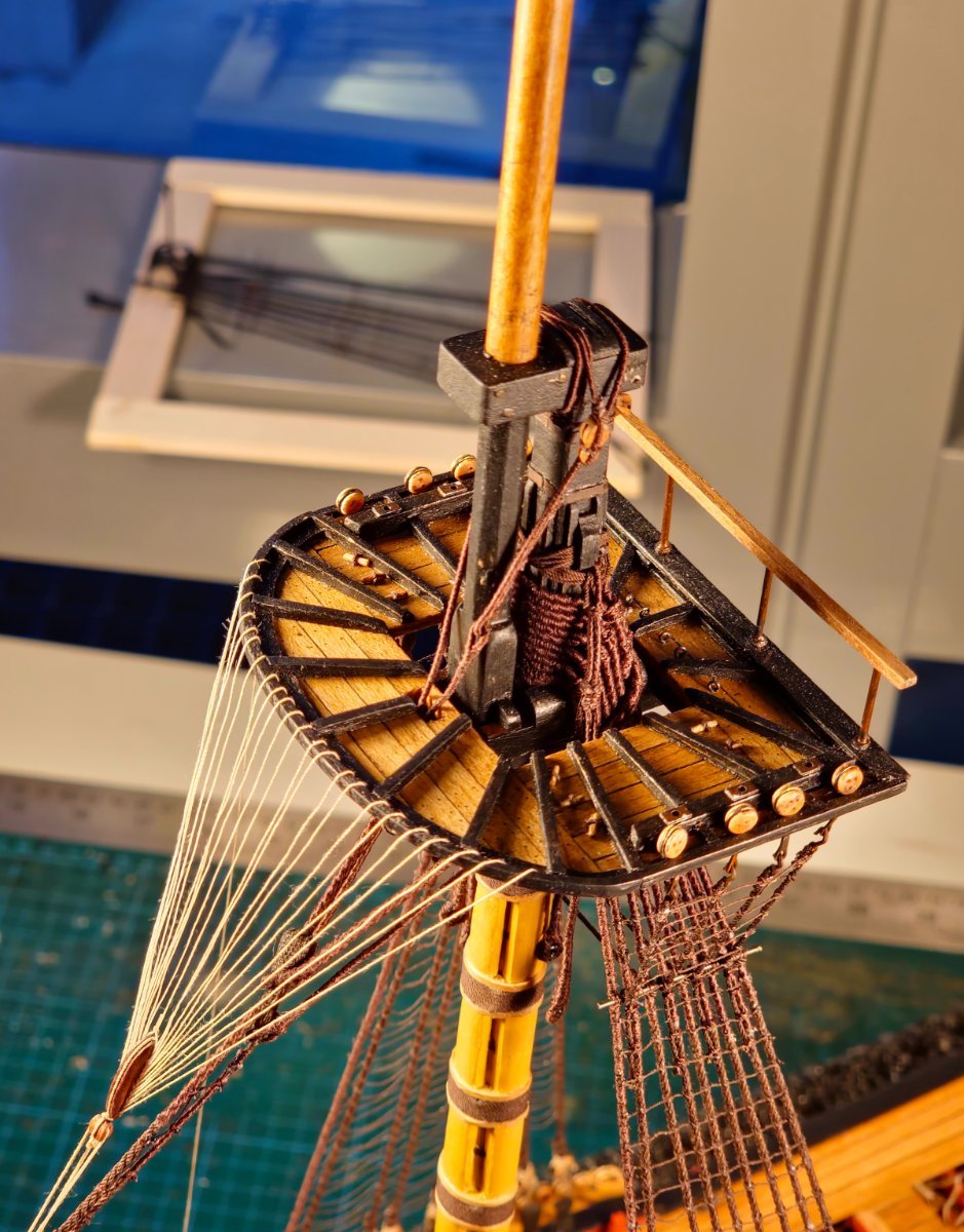
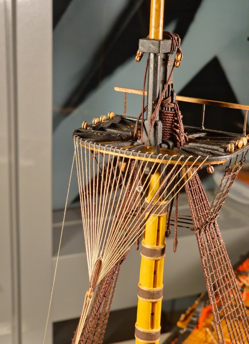
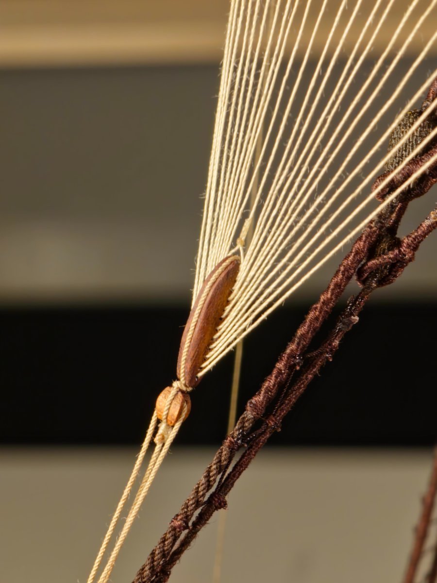
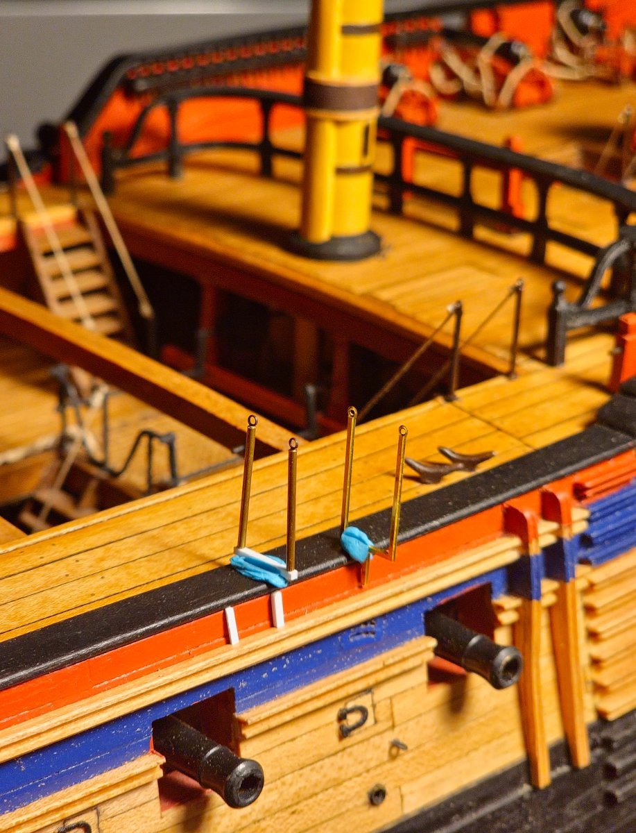
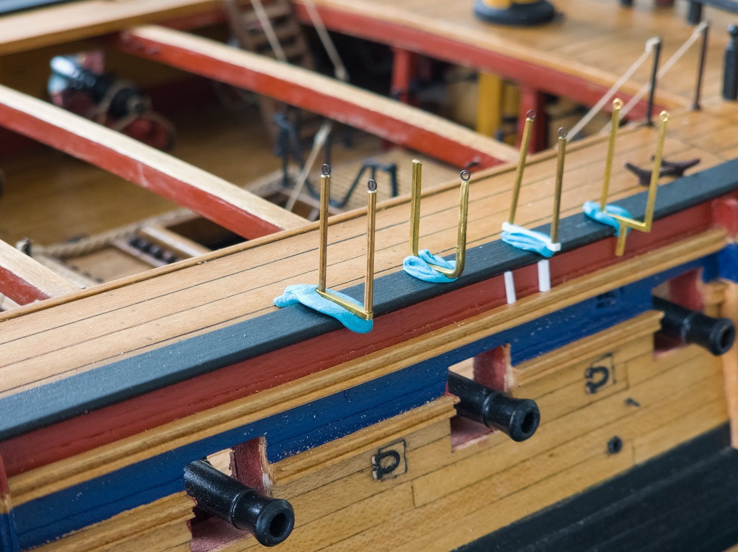
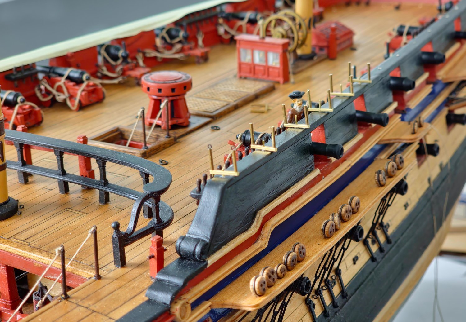
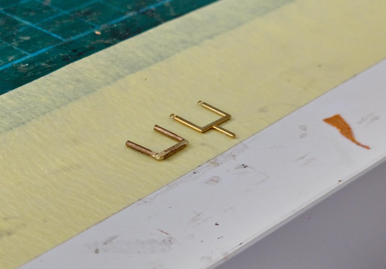
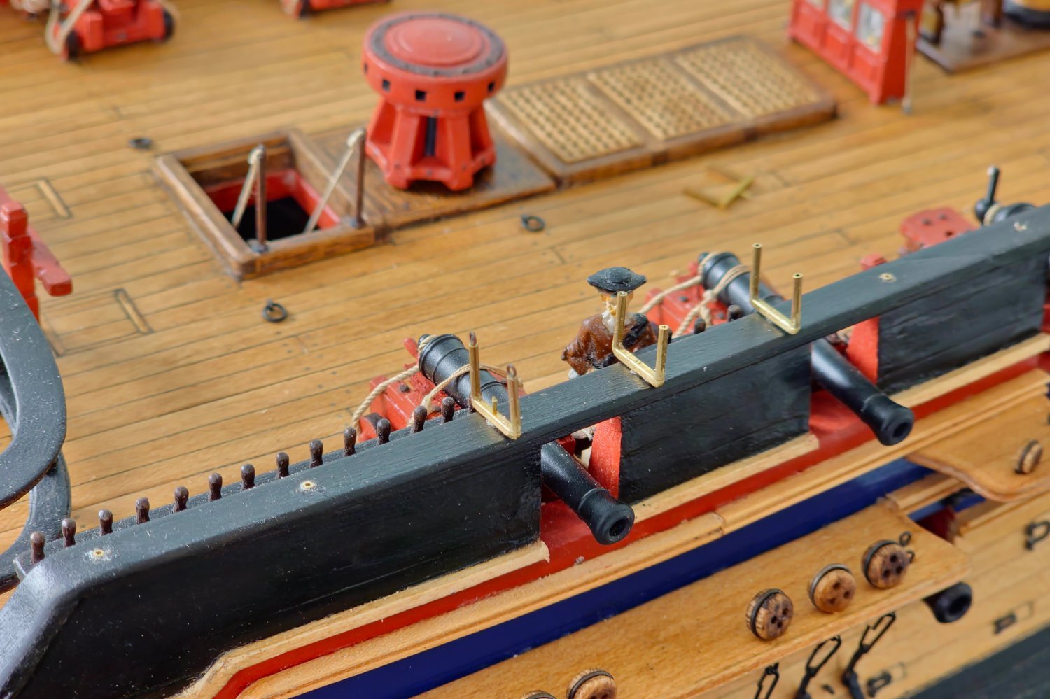
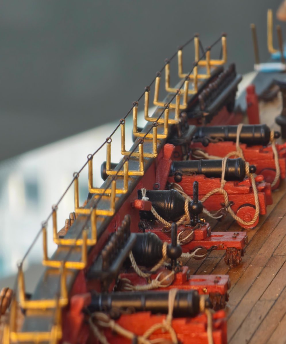
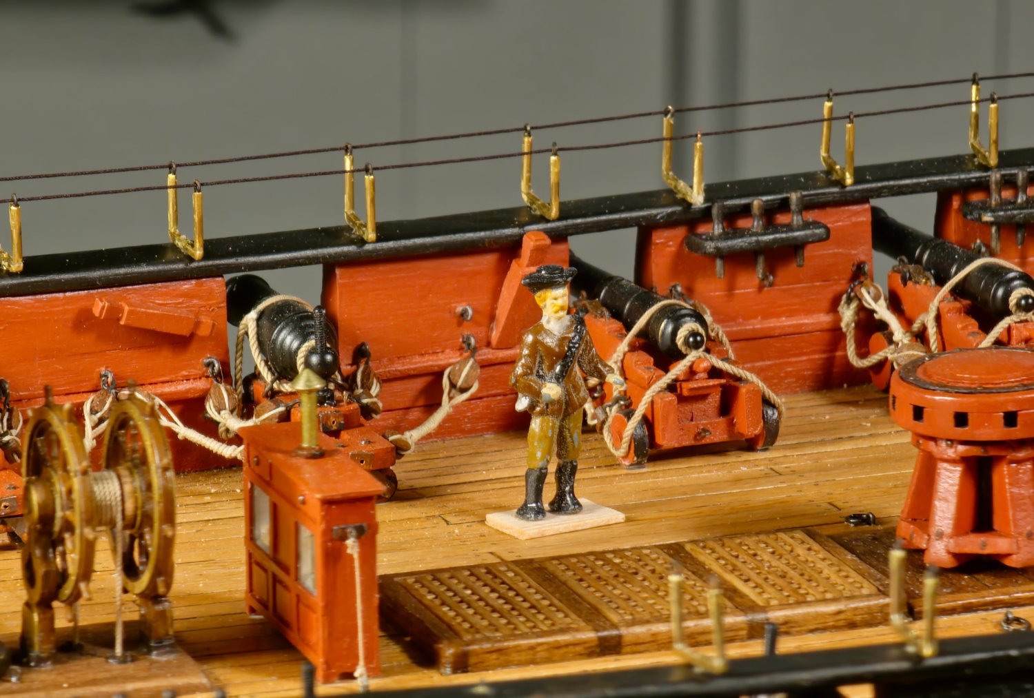
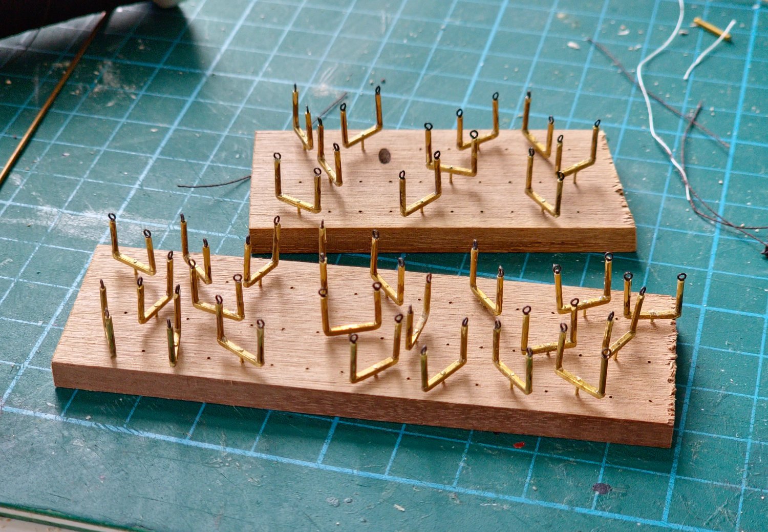
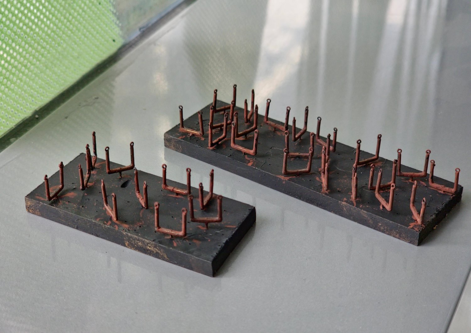
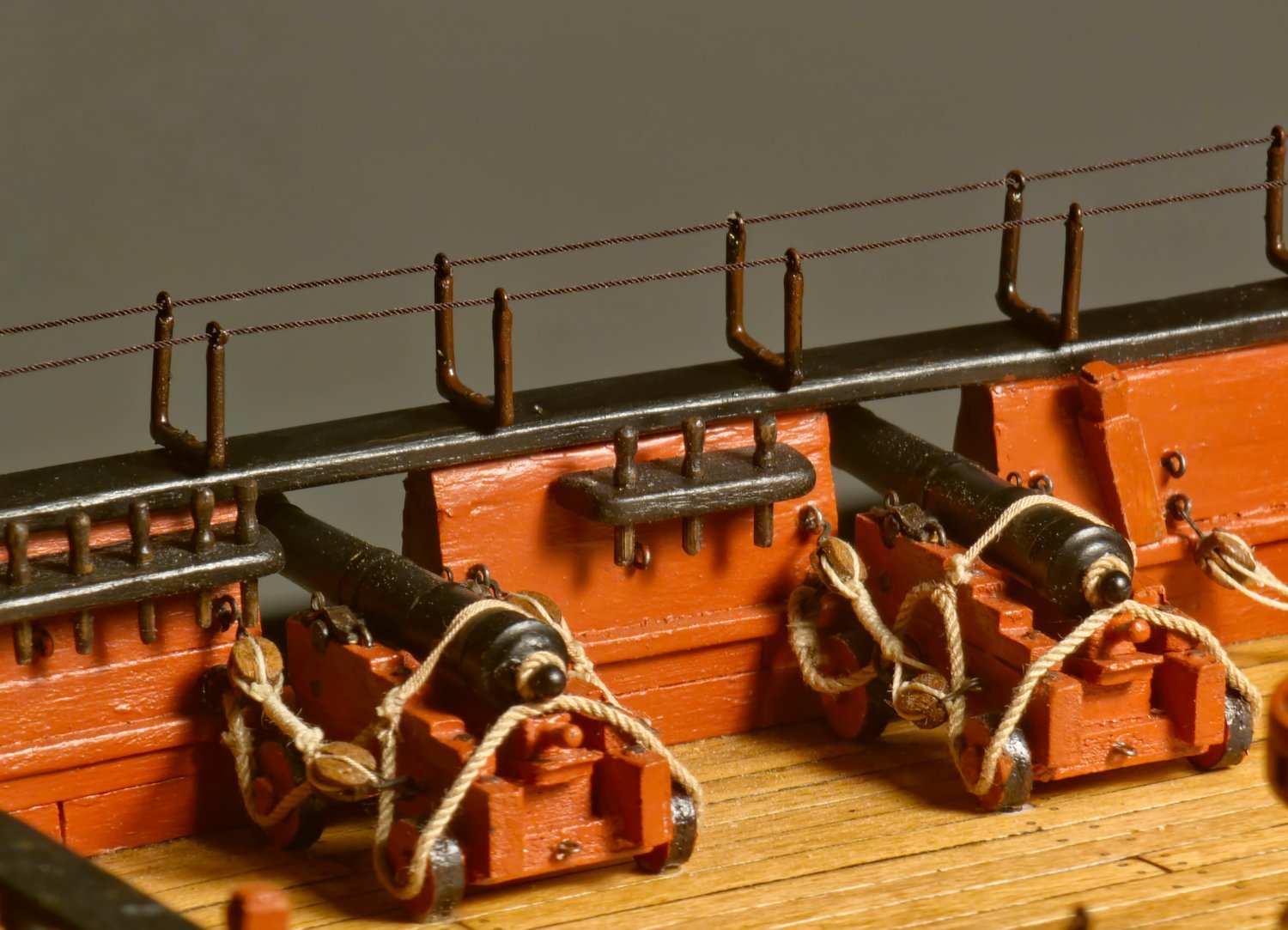
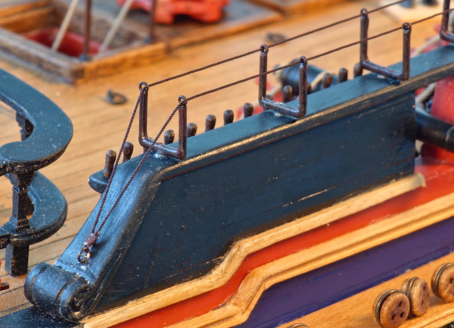
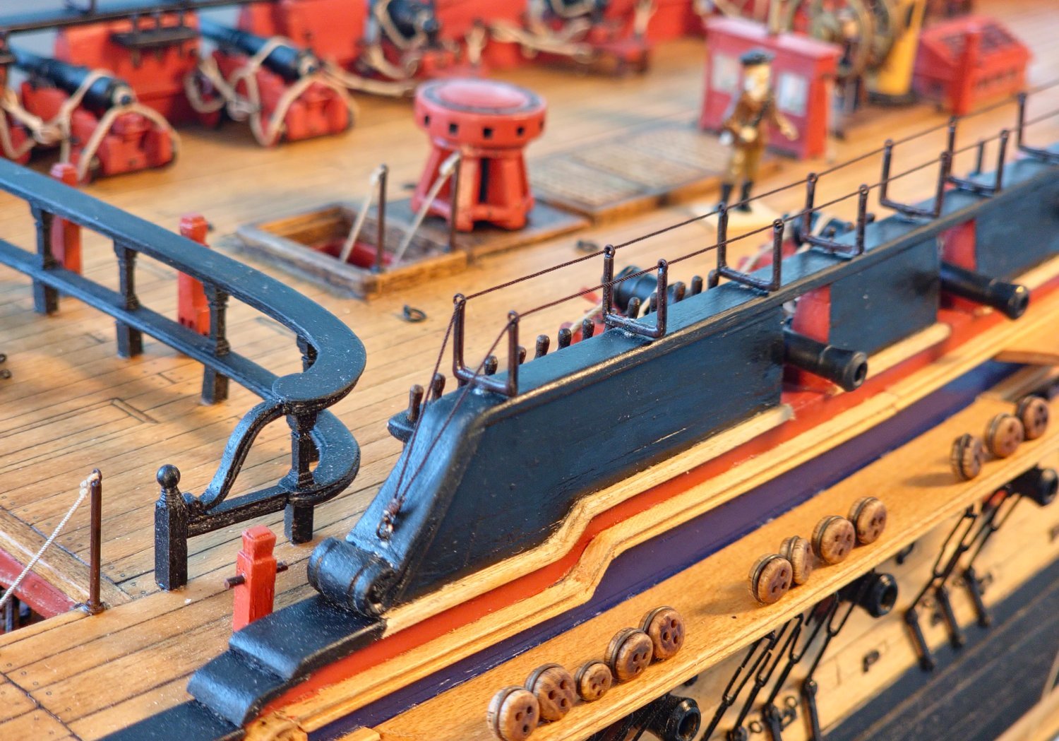
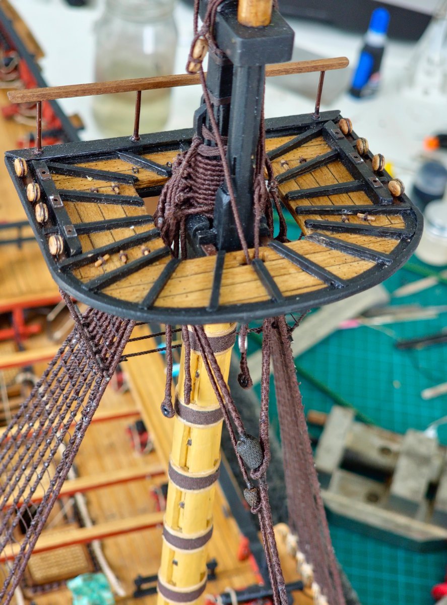
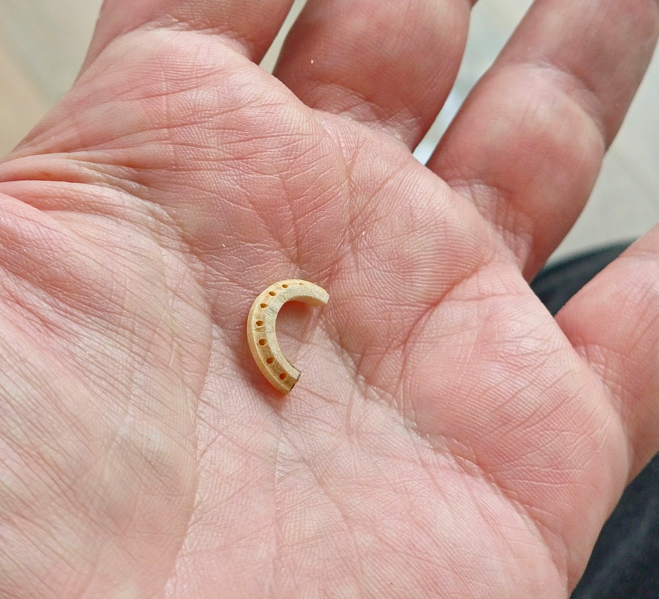
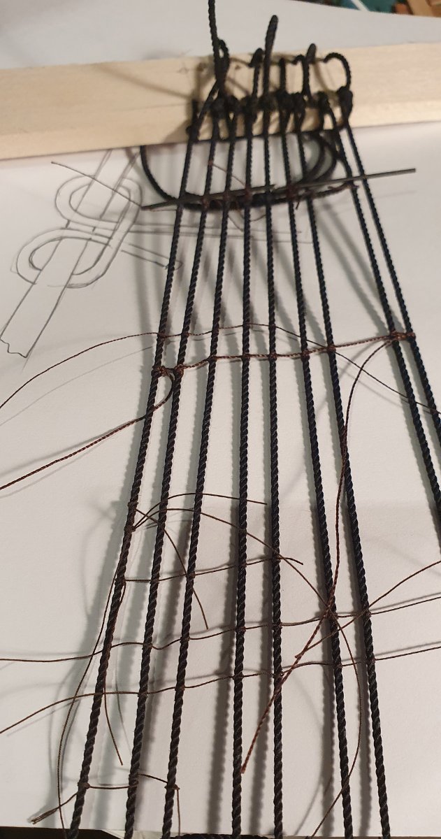
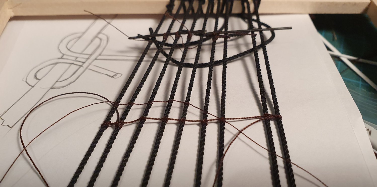
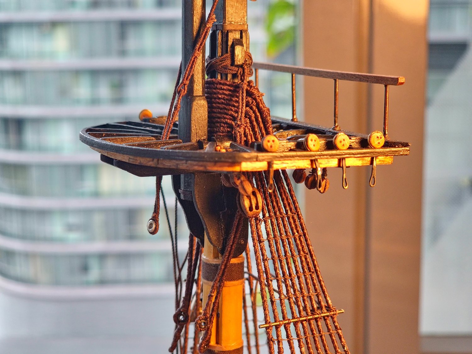
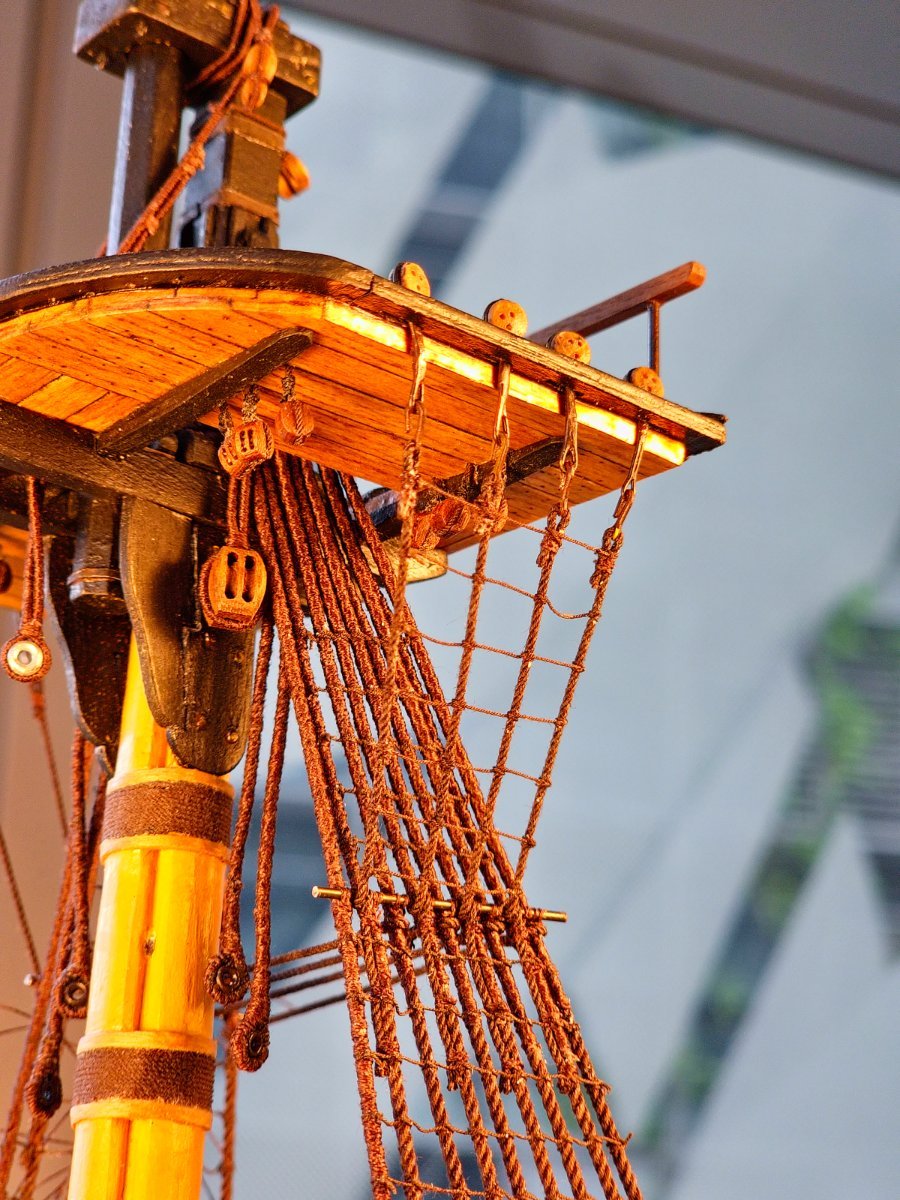
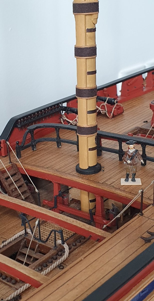
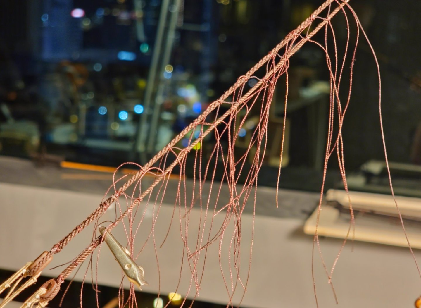
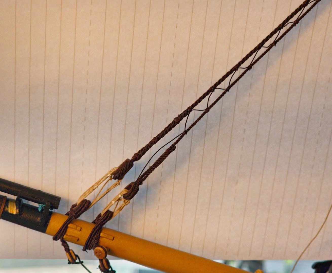
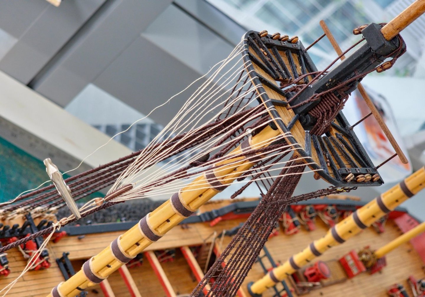
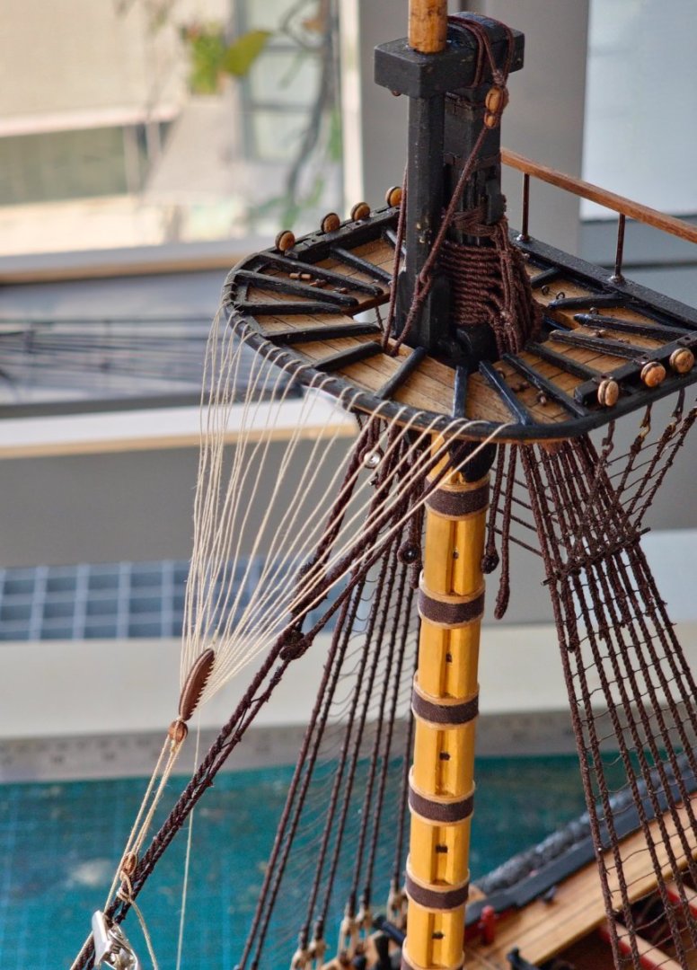
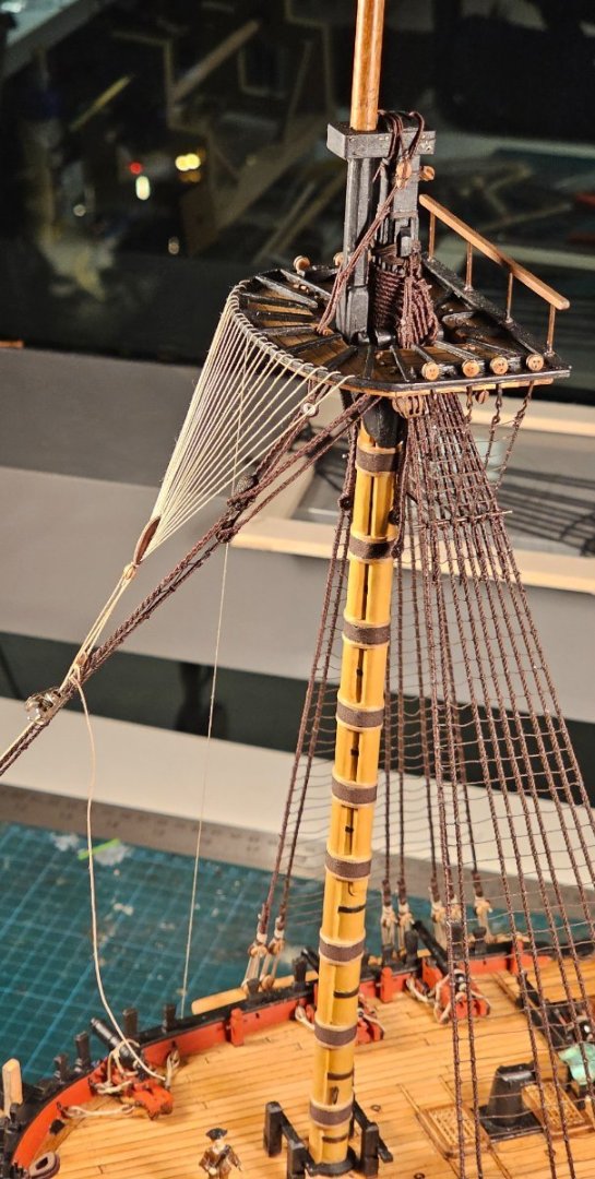
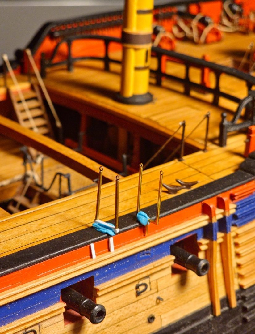
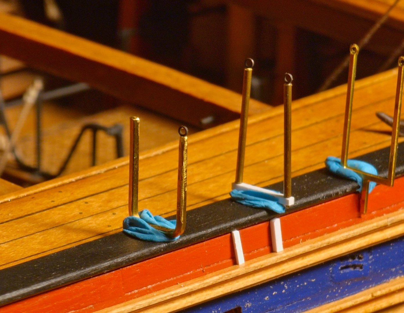
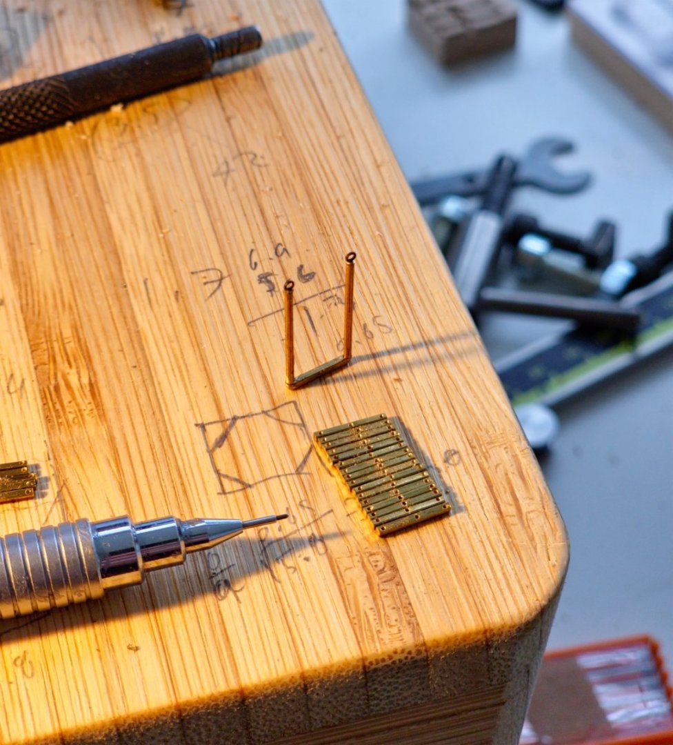
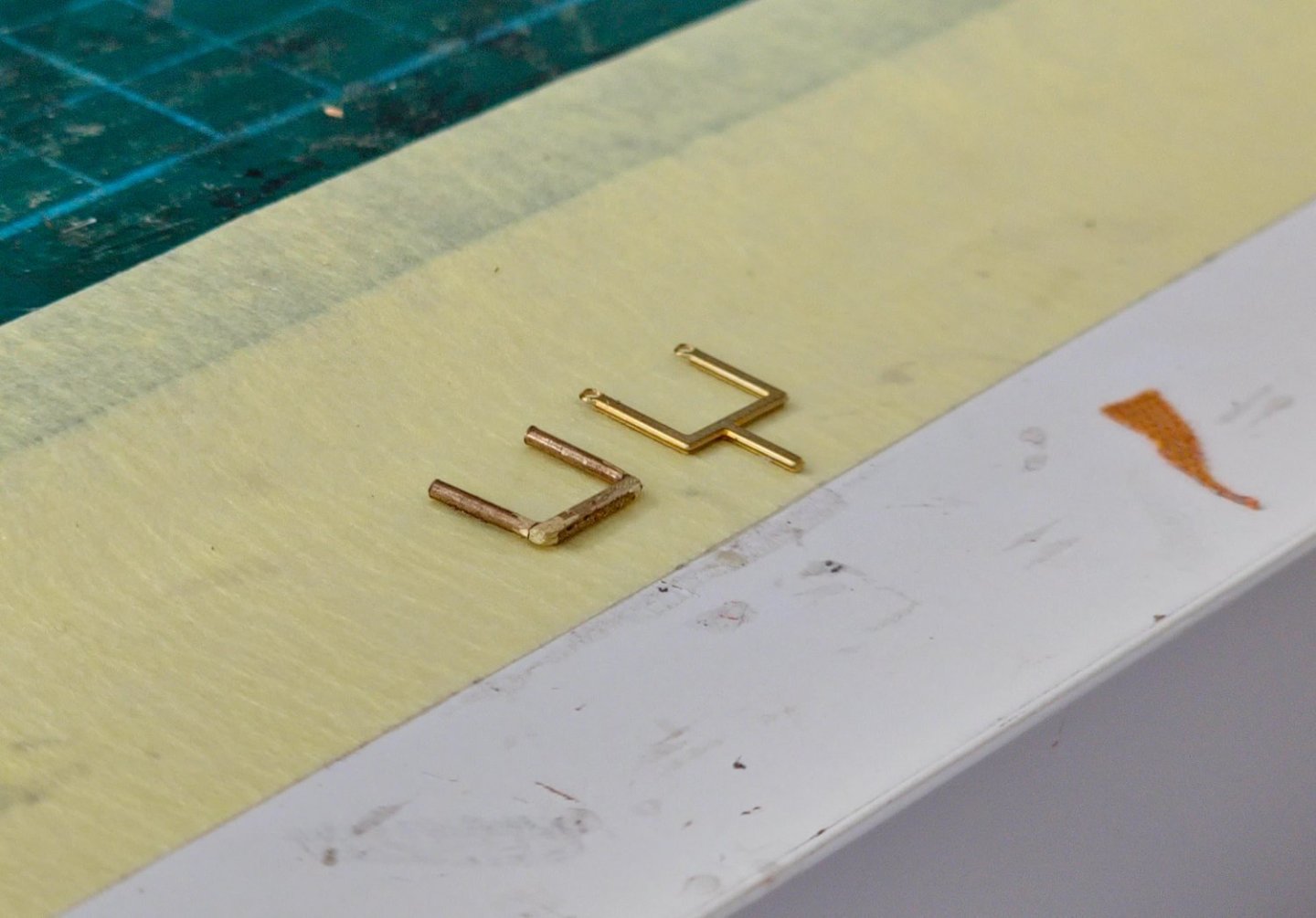
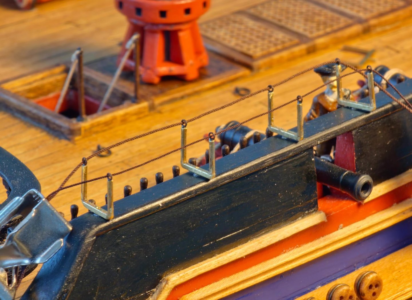
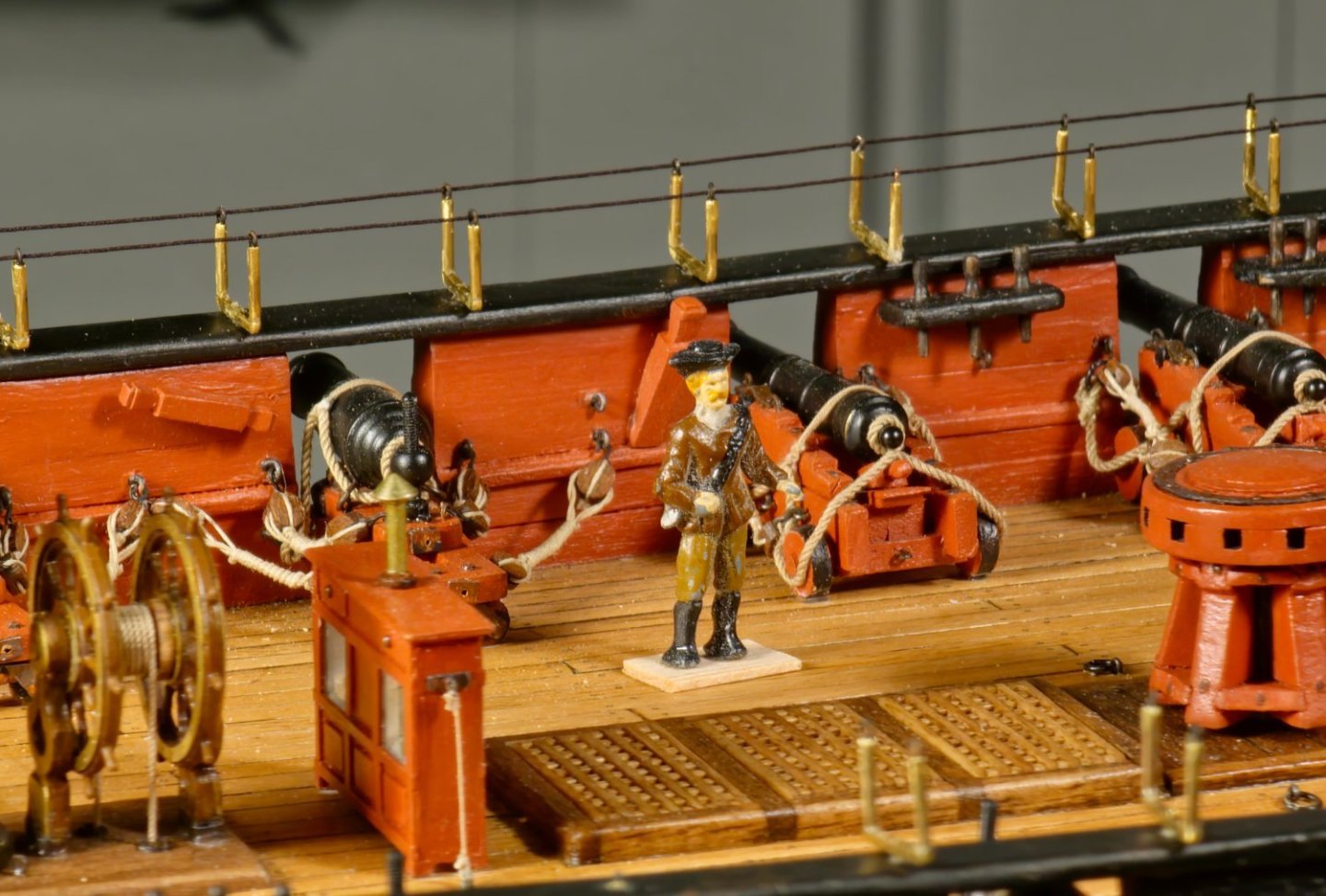
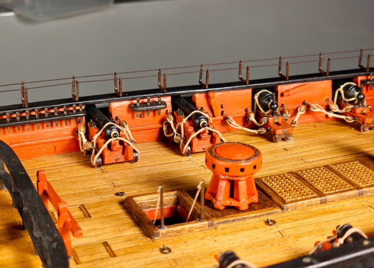
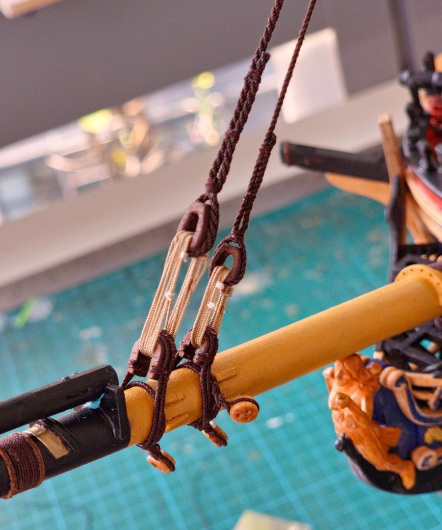
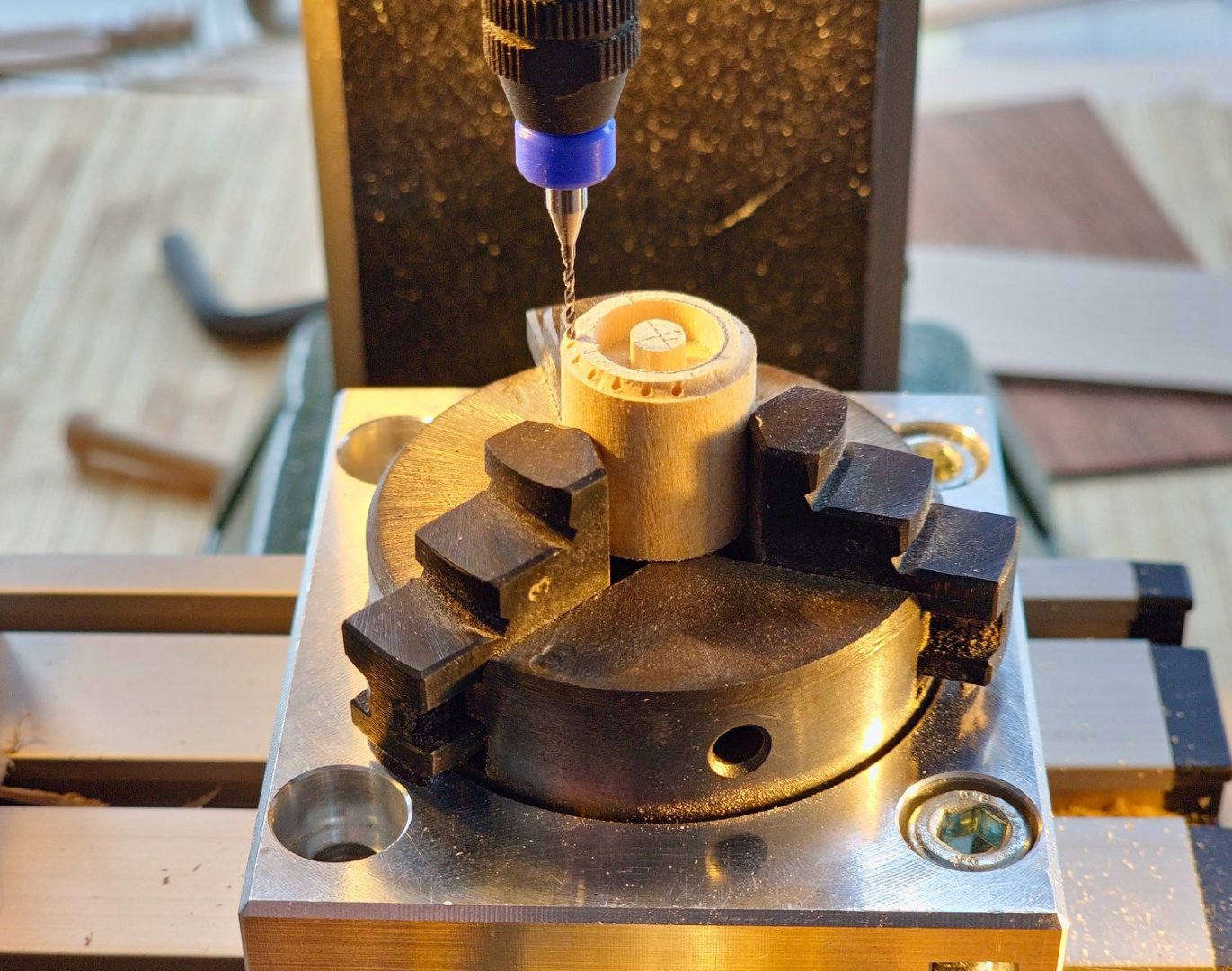
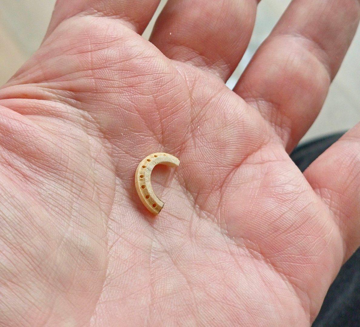
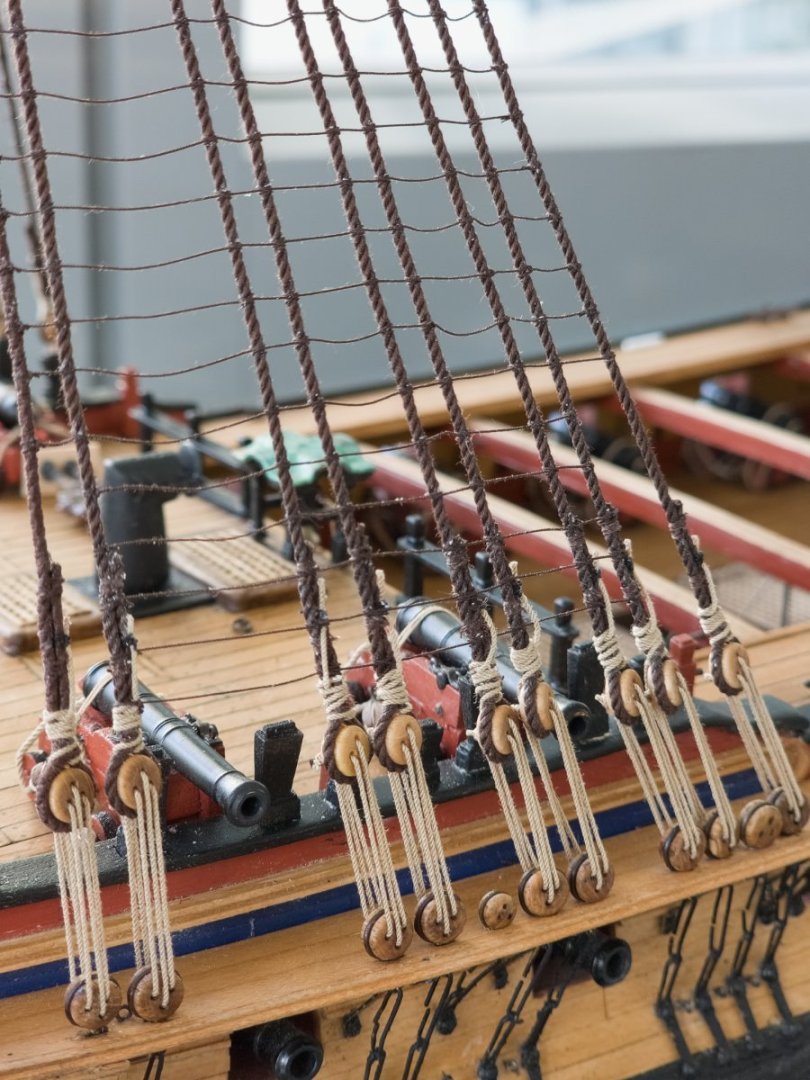
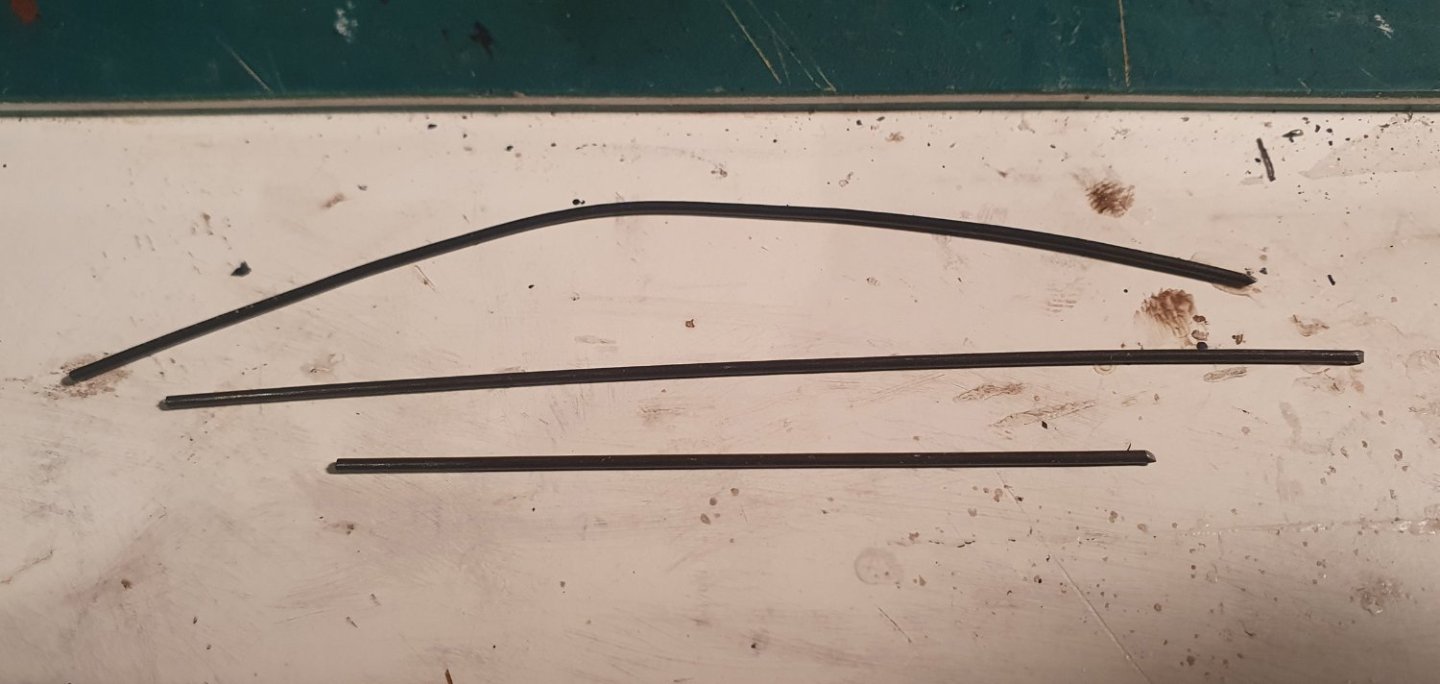
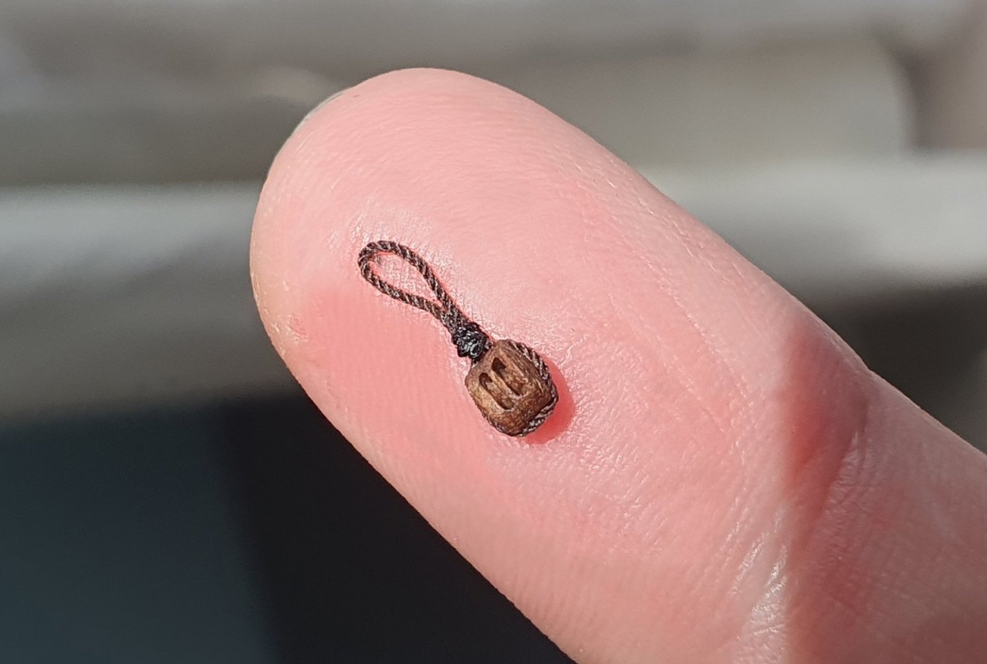
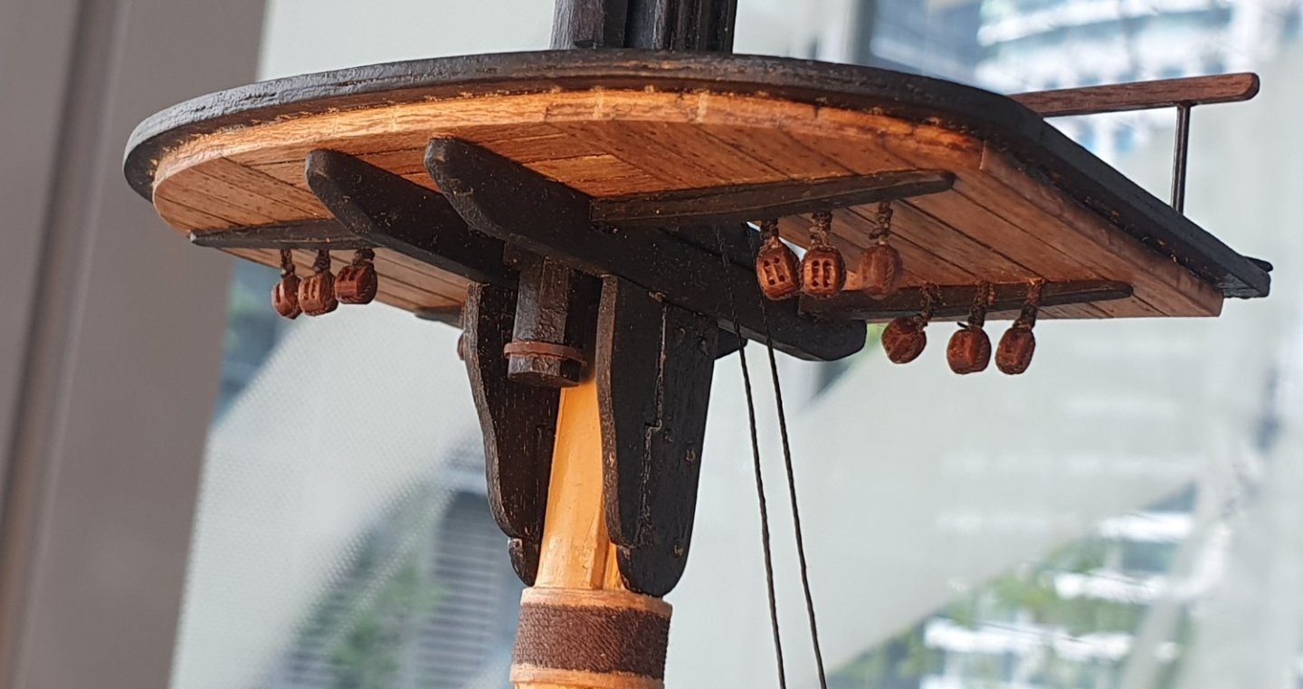
I did attempt to snake between the fore stays. As I feared the result was not great. It is very hard to get all the legs tensioned enough without pulling the two stays closer together so it ended up looking very shoddy. I will probably keep it as it will be hard to remove without damaging the stays. Perhaps I can tweak it a bit using dilute PVA glue and tweezers to get the snaked rope to sit in a more convincing manner. I will have to come up with an alternative solution for the main stay. In the spirit of experimentation, I decided to have a go at the crows feet. I always liked the look of crows feet so decided to include them on my model. Touch and go with the date they fell out of use by but I think it still sneaks under the cutoff. I constructed the euphroe block from some walnut. It was cut to the approximate length and width and then freehand shaped using the dremel and a sanding drum. The block is a little bit longer than the dimensions indicated in Steel otherwise I would have had trouble accommodating the required number of holes. The holes themselves are 0.4mm diameter which should be a delight to thread. I added the blocks which are 3.5mm singles from HiS Models. These were seized to the euphroe block using 0.5mm ROS tan rope. For the crows feet I used some 0.1mm rope I had lying around. I think it is Caldercraft. Steel gives a scaled diameter for this element at 0.12mm so it is close enough and I have heard that thinner is better when dealing with crows feet. I rigged it according to the diagram in Lees. I had 23 holes which equates to 11 per side and one in the centre which gave me 12 holes in the euphroe block. This agrees with Lees who states that the euphroe block generally had between 12 - 14 holes. Once installed I realised that I had bungled the counting and I have 25 holes. I should have drilled 13 holes in the euphroe block. I am just going fill in the unused holes in the top as threading this was a real pain. It was quite the tug of war to get everything taut. I did not know how far down the stay to fix the euphroe block but looking at historical models it would appear that in early 18th century ships it sat quite far down the stay but this seems to have retreated further up the stay as the century progressed. In the end I just picked a location on a whim and then moved it twice until I was vaguely happy with it. I somewhat naively thought that a good tug on the euphroe block would cause all of the crows feet to snap tight but I soon found that this was not the case and each line has to be pulled taut in sequence cycling through line one to line twenty three several times over which caused much grinding of teeth. The result is still a bit floppy but I think I will let the ropes rest for a bit before giving them a final tensioning. I started looking at the hammock cranes as I realised that I should get some of these installed before I fit the shrouds for the main and mizzen mast as there would be access problems once these were in place. The PE kit supplied items are quite serviceable but to get the thickness they have sandwiched two layers of brass sheet and the join is visible along the side. I was also distressed by the fact that they are rectangular in cross section rather than square. Minor points I know but once you have an itch you must give it a good scratch. A spot of research showed that there was quite a bit of variation in the design of these items so that gave me a free hand in coming up with something I could manufacture in-house. I thought about using the same thin-walled brass tube that I constructed the handrail stanchions from. I then used a 1x1mm section of styrene to complete the bottom member but the styrene did not have the required stiffness and tended to flex too much. I then went out on the hunt for some 1x1mm brass square section to replace the styrene but this proved elusive. I eventually found a model supplier in the UK that sells it online so I ordered some. It is quite small but probably slightly larger than the real section used however this is the smallest I could go before it became impractical. Once I had the 1x1mm brass section I realised that I could form the hammock crane by simply bending it into shape. Getting a nice tight radius was quite problematic as was drilling the holes vertically into the ends to accept the eyebolt. I may use a modified version of this method for the waist hammock cranes but continue with the brass tube method for the quarterdeck locations. The kit drawings show 15 hammock cranes per side at the quarterdeck while the AOTSD indicates 17 per side. I ended up with 16 which made sense for the spacing of gunports that I have. To install these, I inserted a section of 1mm diameter brass tube flush with the top of the rail. This will theoretically be able to receive a 0.5mm diameter brass rod that I will insert through a hole in the bottom member of the hammock crane and should hopefully keep them in place although it seems a bit tentative. Drilling the 0.5mm diameter hole in the brass sections really tested my patience but I had started so I had to finish. I snapped quite a few drill bits trying to force the pace. They were all held together with epoxy and given a bit of a grinding with the dremel to smooth the transition between the vertical and horizontals and hopefully, but ultimately unsuccessfully, make them look like they were beaten from an iron bar by an angry blacksmith. I inserted a 1.5mm diameter blackened PE eyebolt from HiS models into the top of the legs. I made a bit of a mock-up showing different rope sizes for the top rope. The tables in Steel are a little ambiguous as to the size of this rope. It could either be equivalent to 0.5mm diameter or 0.35mm depending on how you interpret them. I suspect the 0.35mm is the correct one which would be the 3inch circumference rope to the "stantion in the wafte" noted in Steel but I do not mind the heavier rope. It is quite the task to complete these and I did them in batches of eight as I found that this is the maximum I can assemble before the epoxy hardens. It is another one of those endeavours where there is a lot of work for a marginal gain on the kit supplied material. They are finished with a coat of matt rattle can black, some weathering powder to make them more iron like, a coat of polyacrylic and then glued in place. They are a bit chunky looking but that is as small as I can go without learning some new techniques. They would look better on a 1:32 scale ship. I will now have to hit the textile shops to see if I can source some convincing netting material.


-
Thanks for the kind words Dave. When you live close to the equator every month is a summer month. Regards, David
-
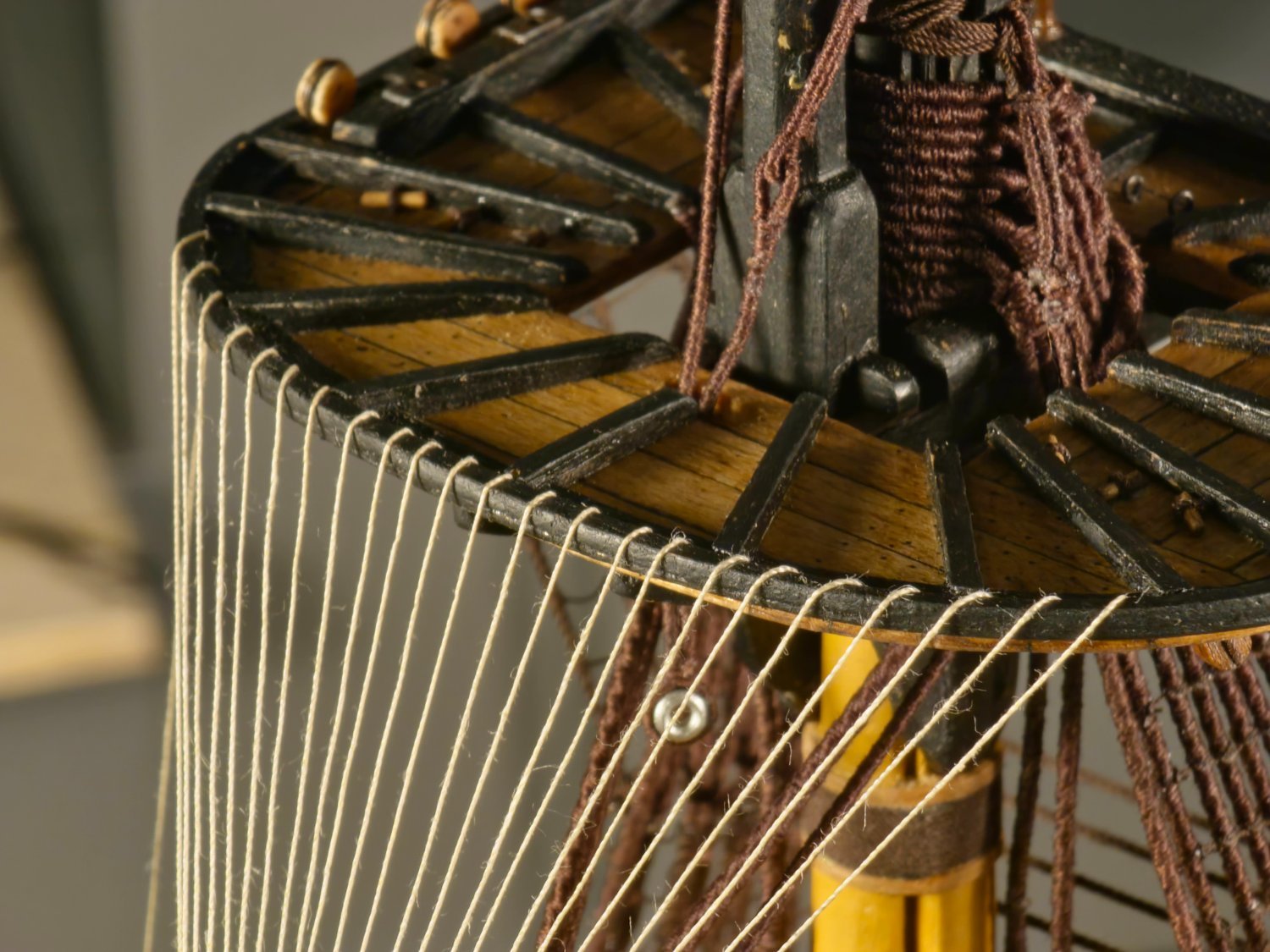
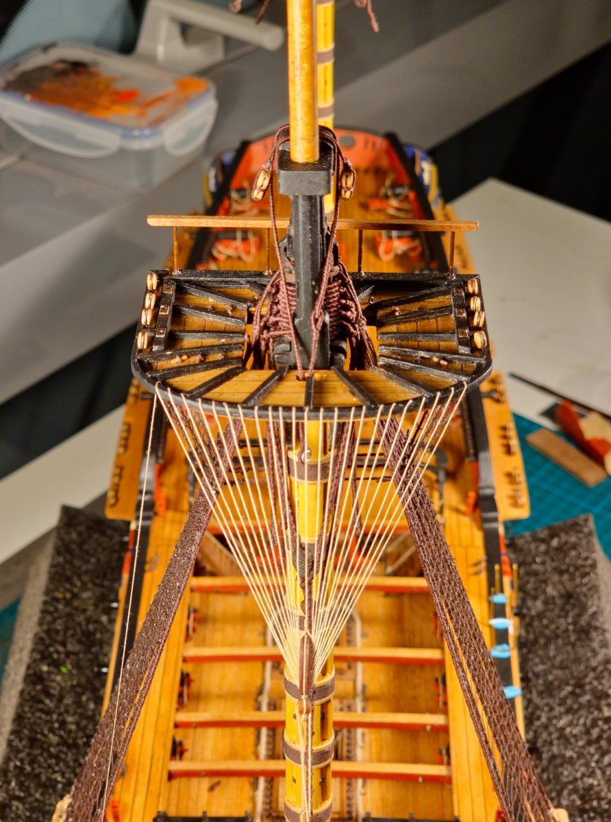
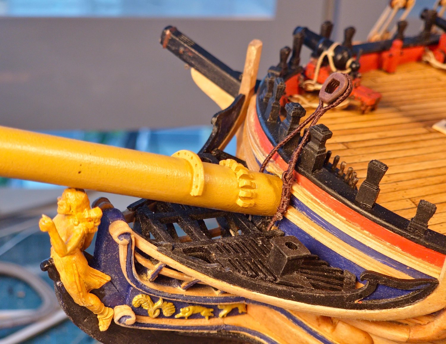
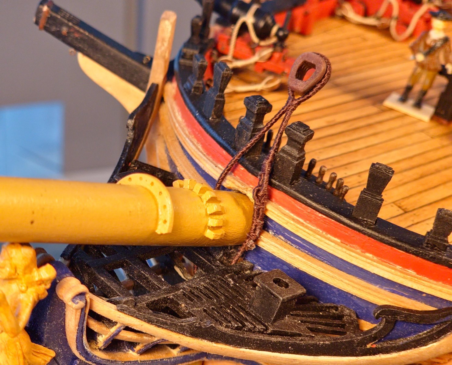
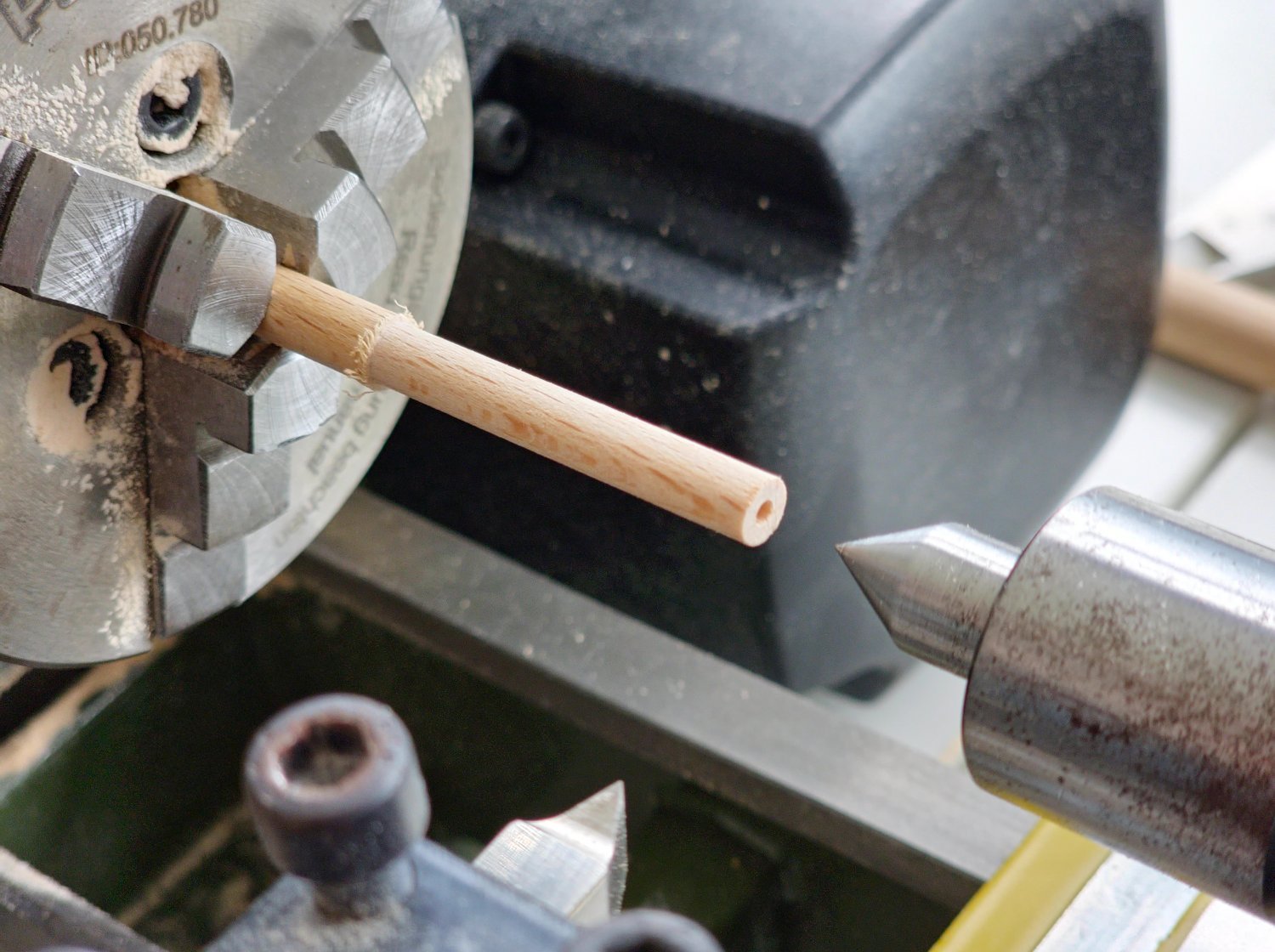
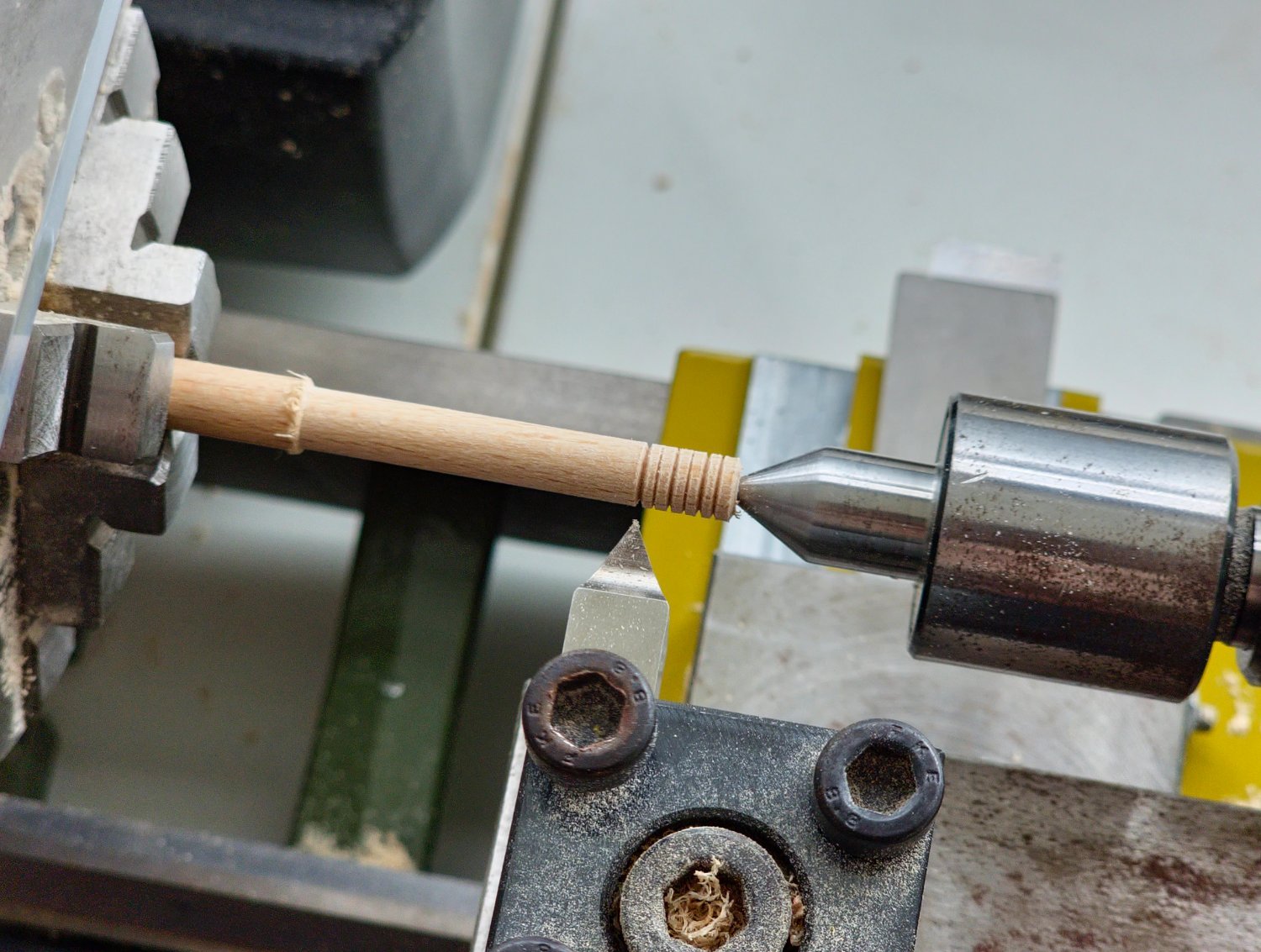
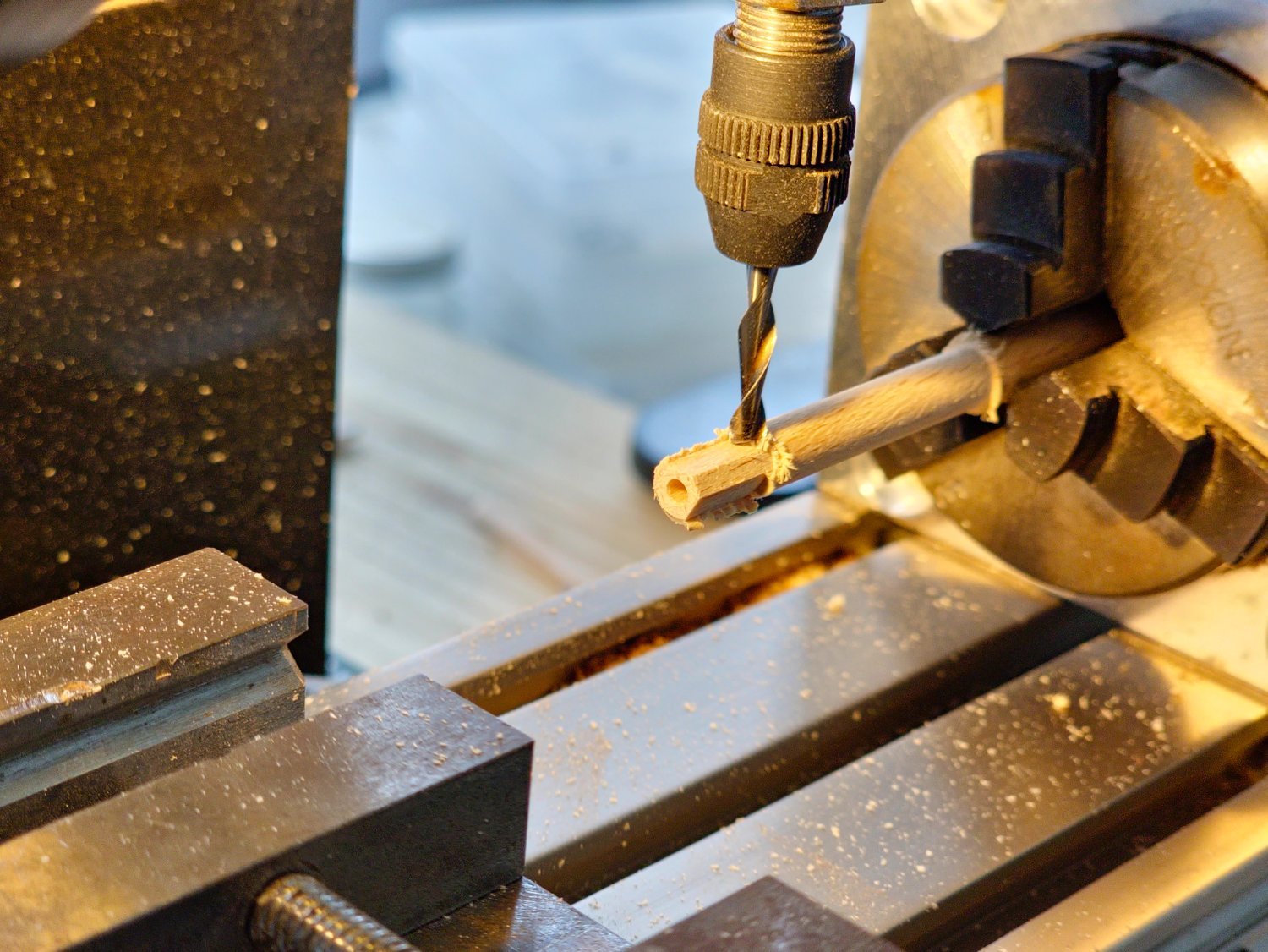
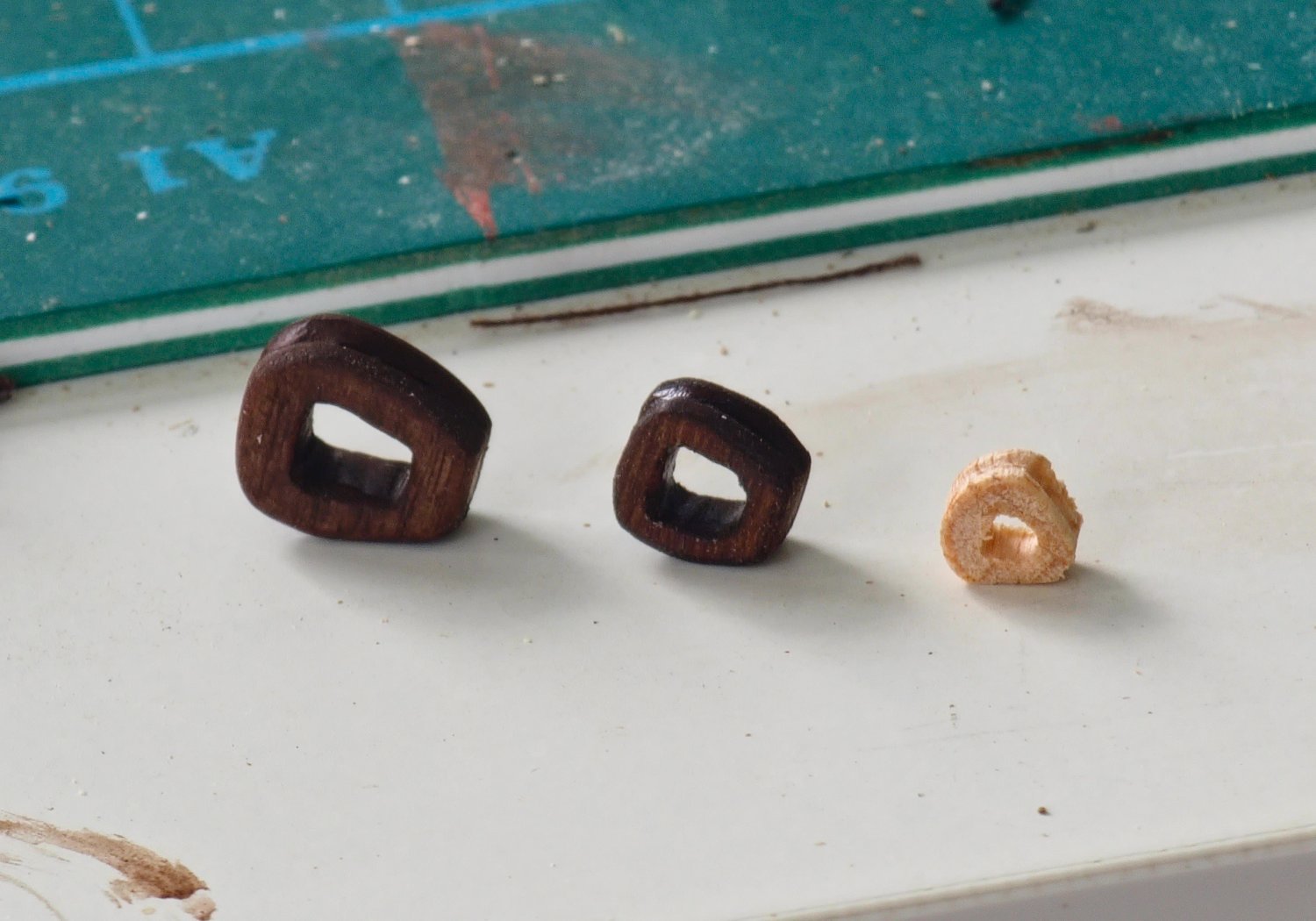
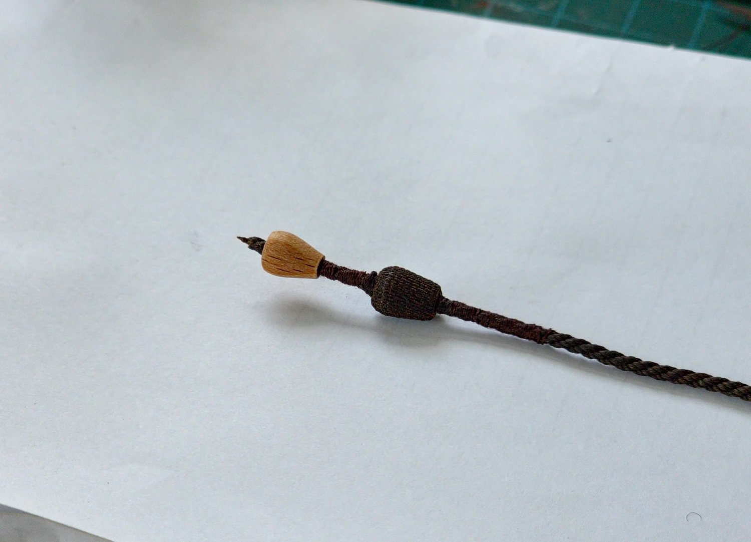
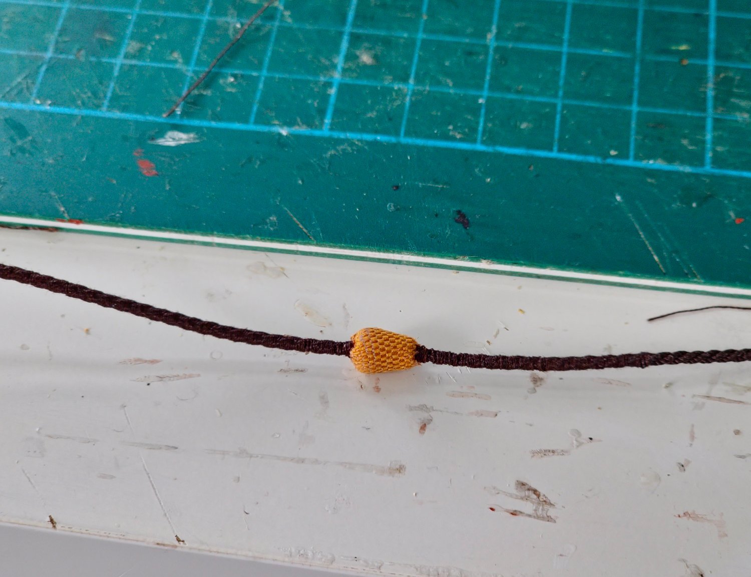
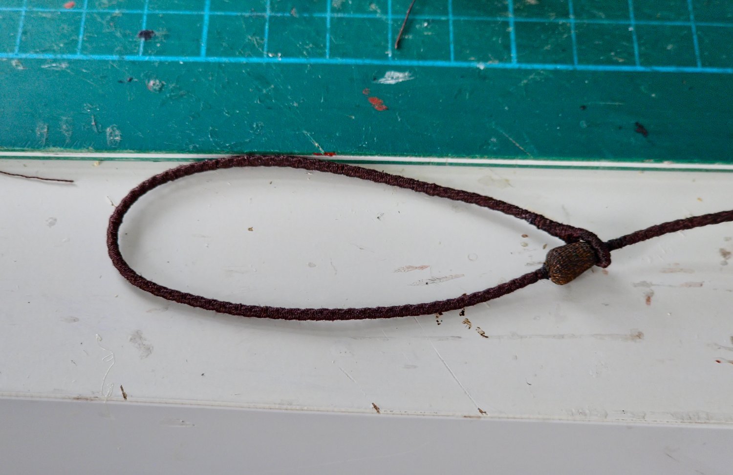
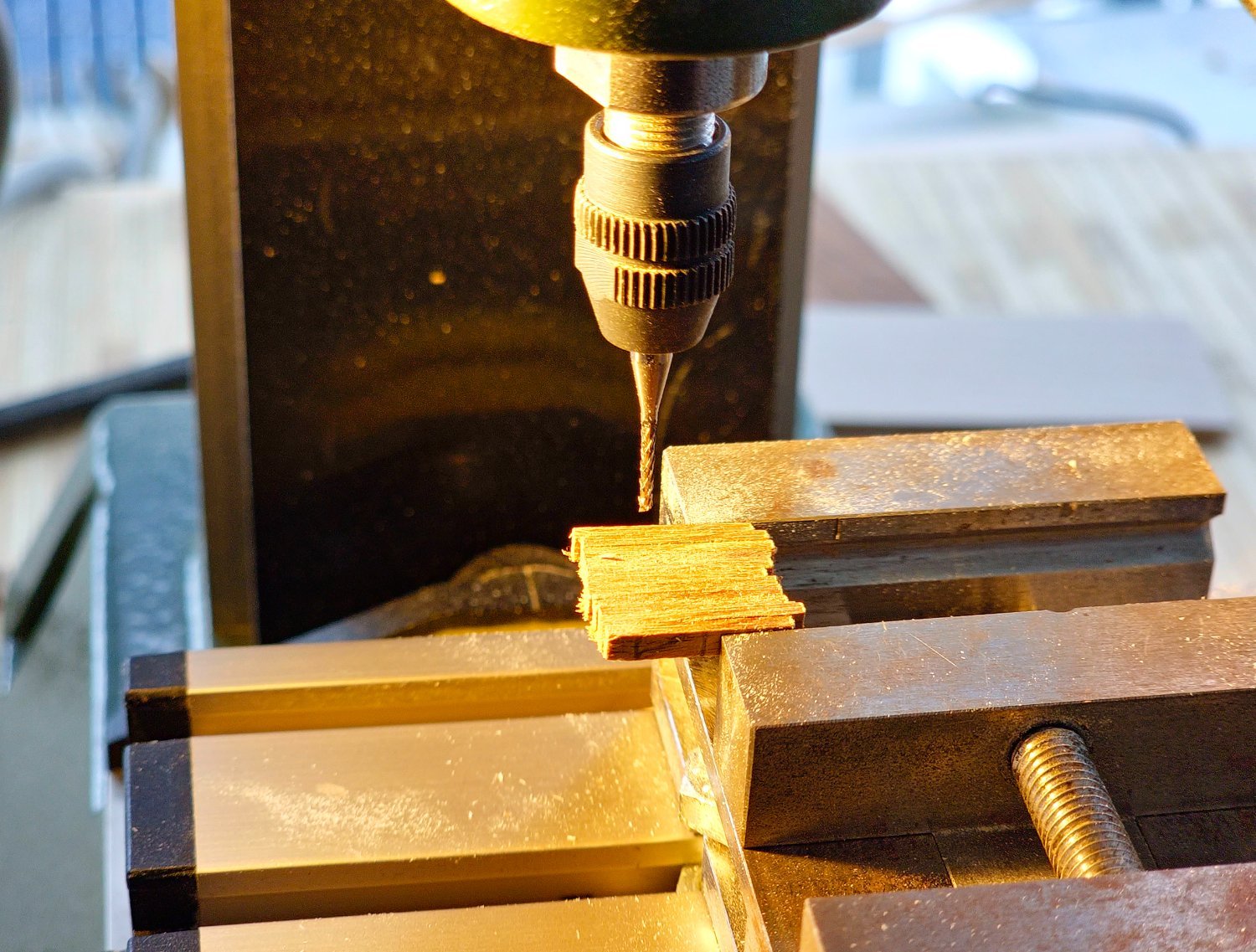
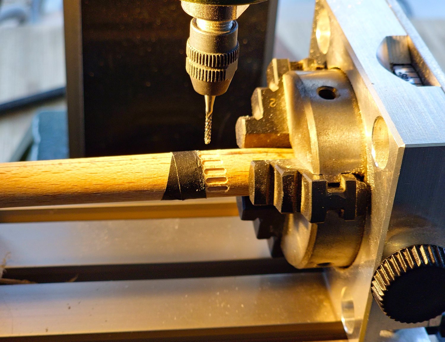
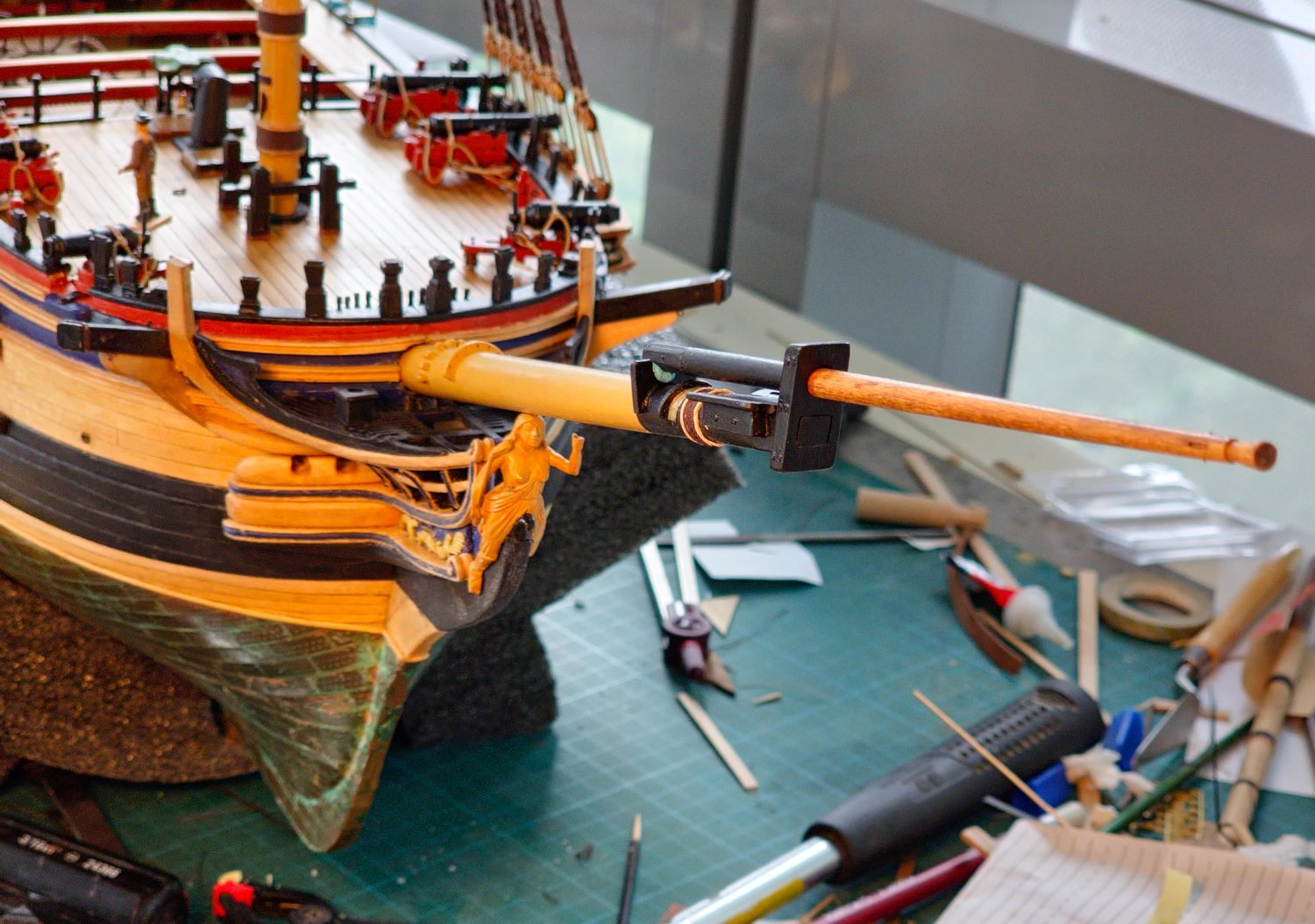
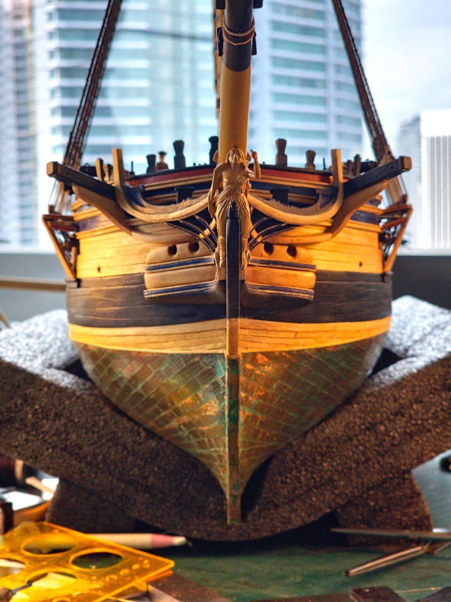
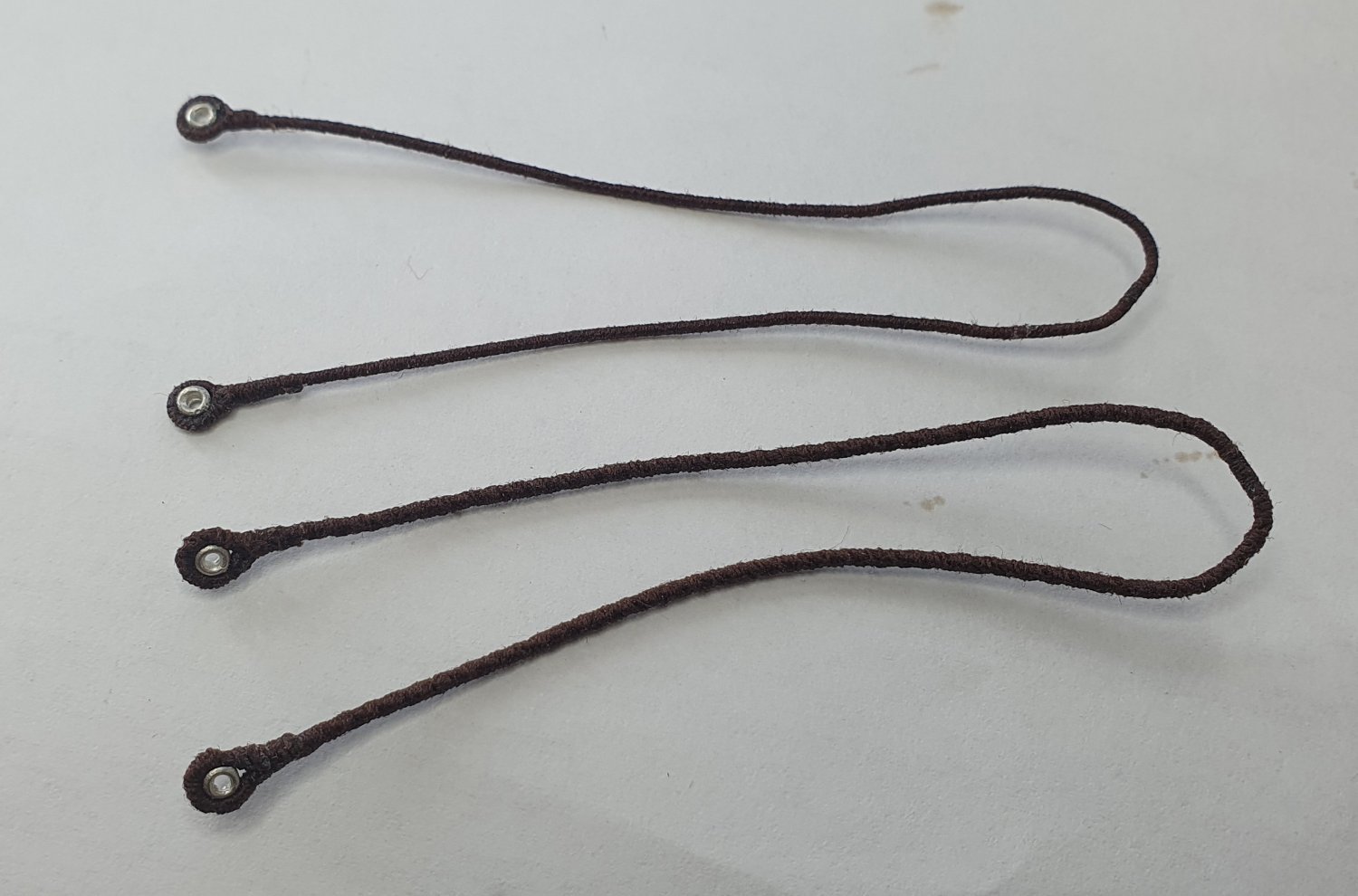
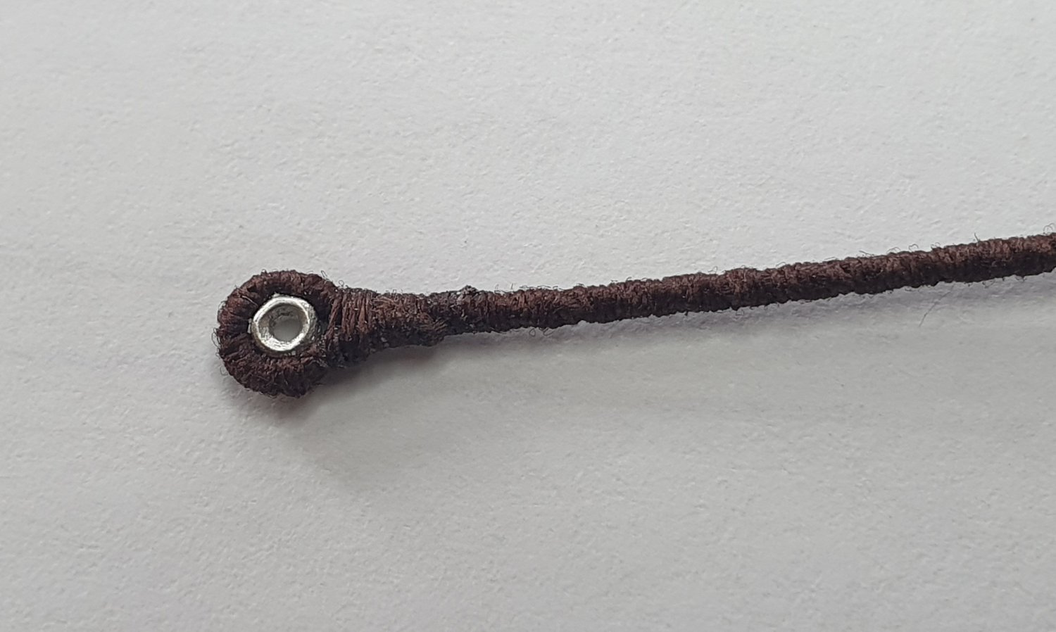
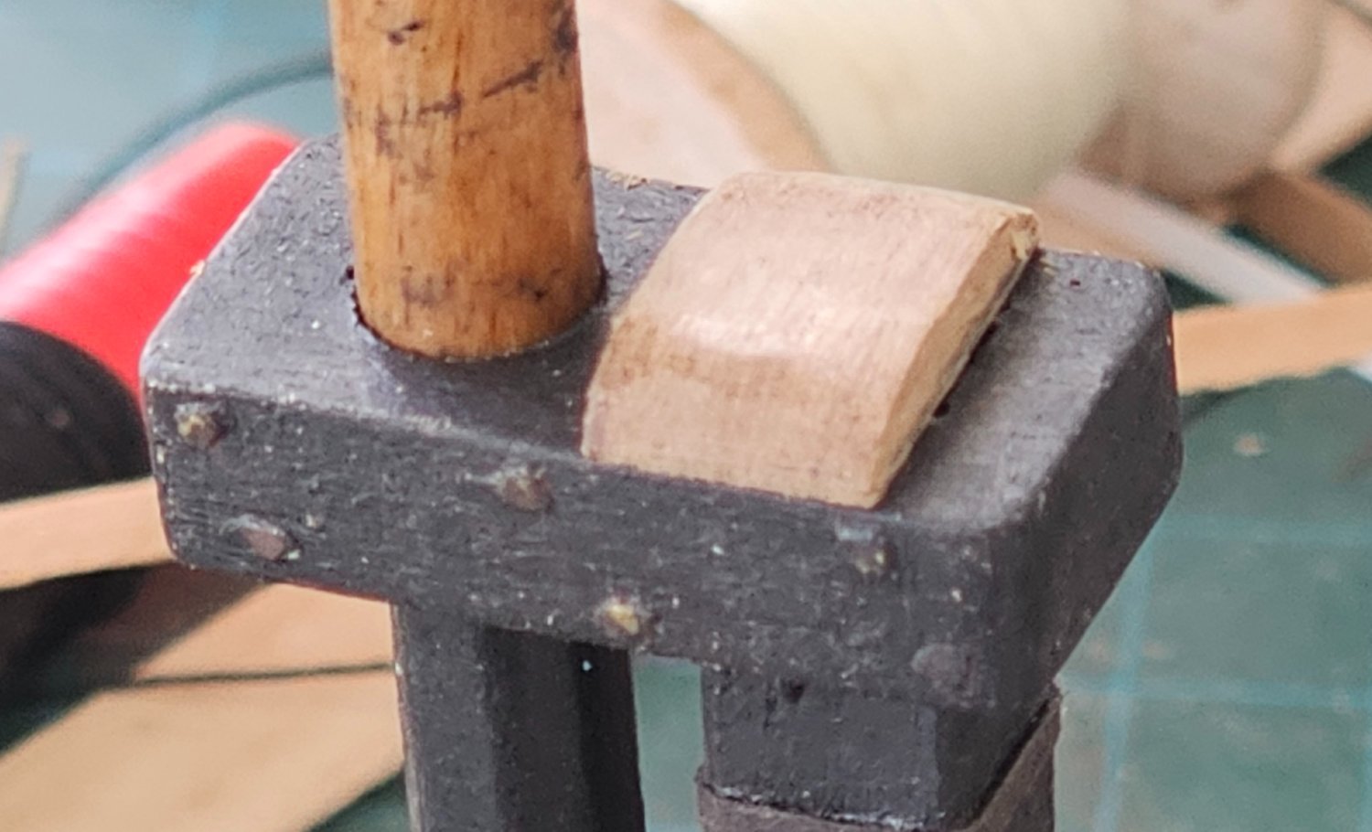
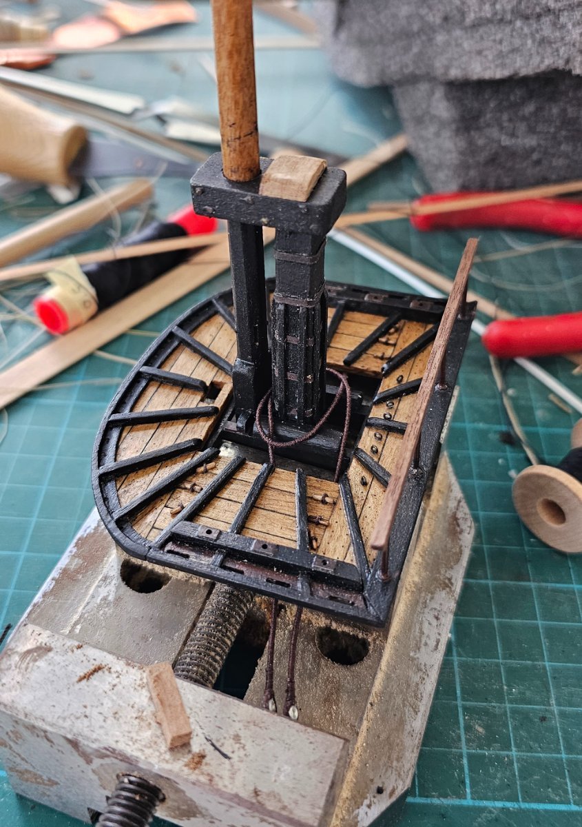
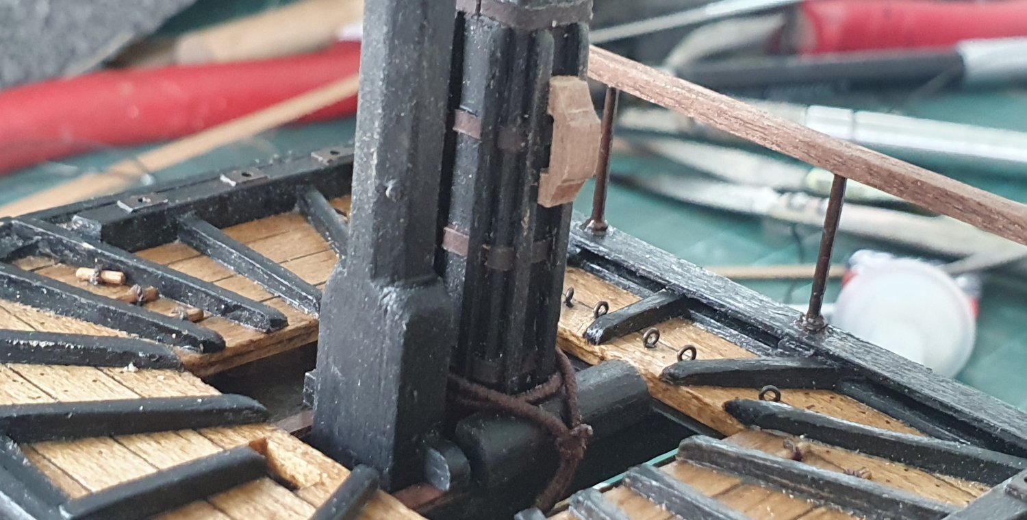
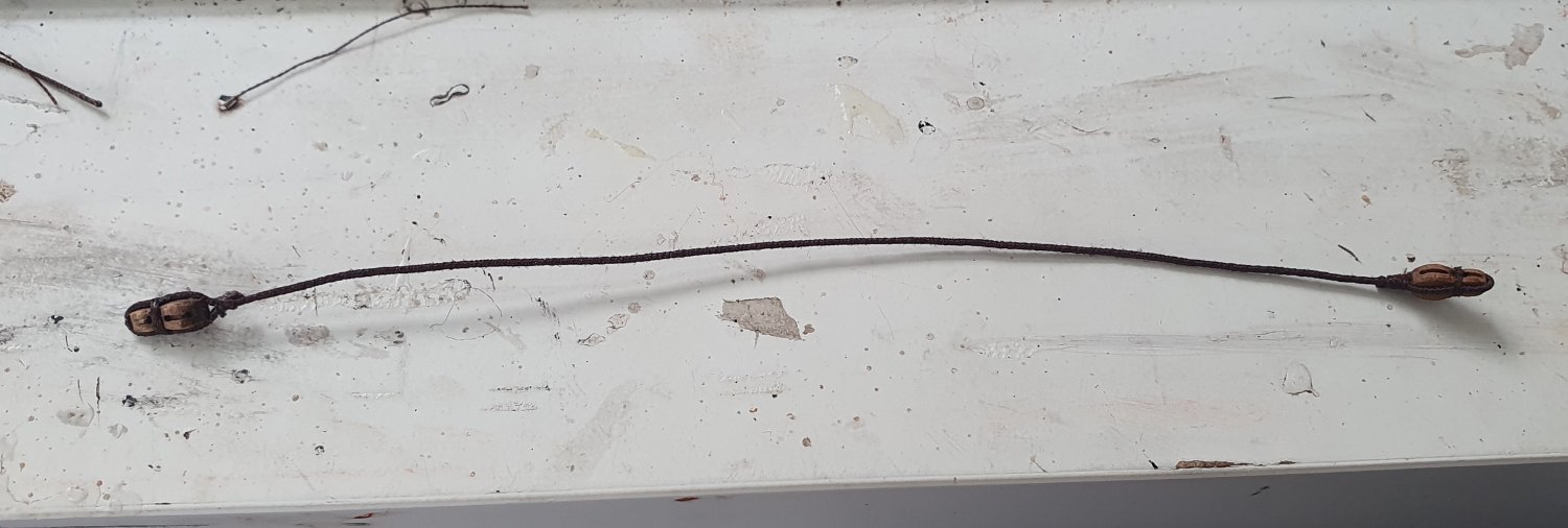
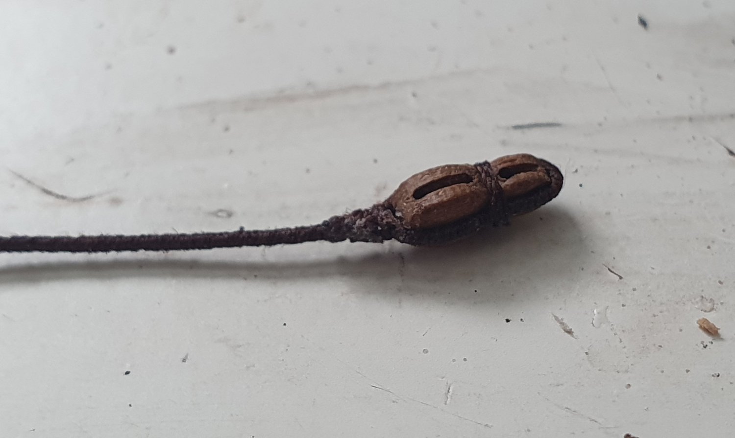
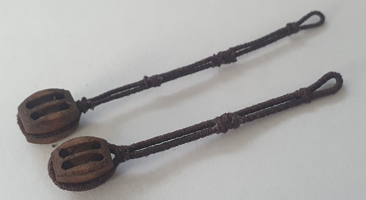
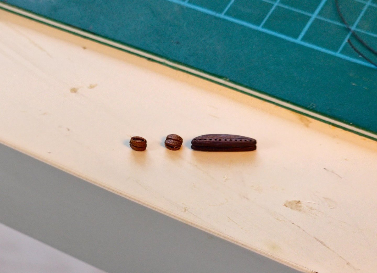
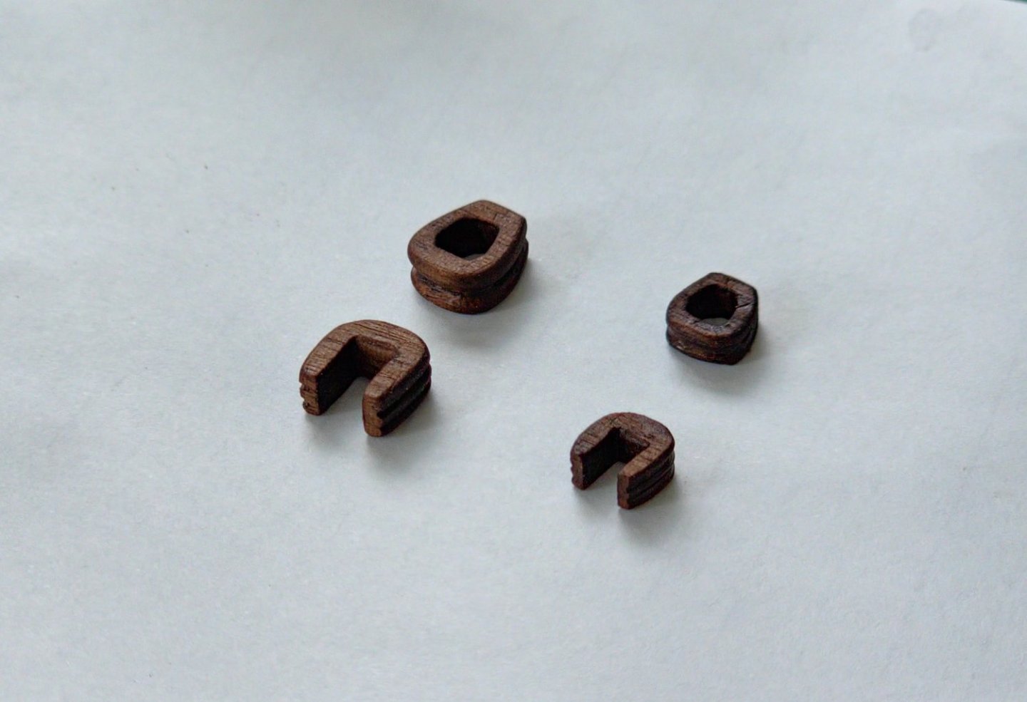
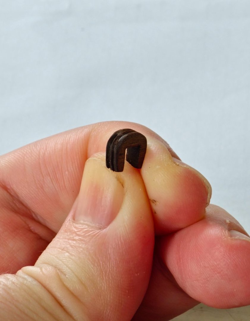
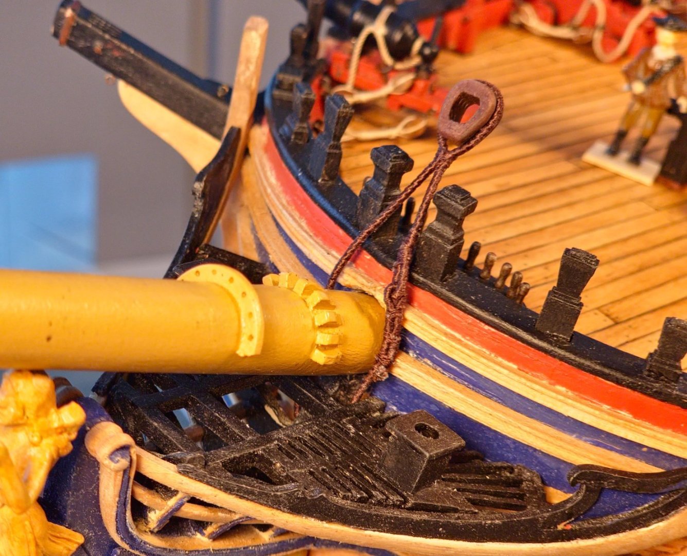
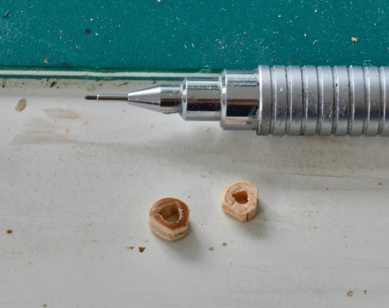
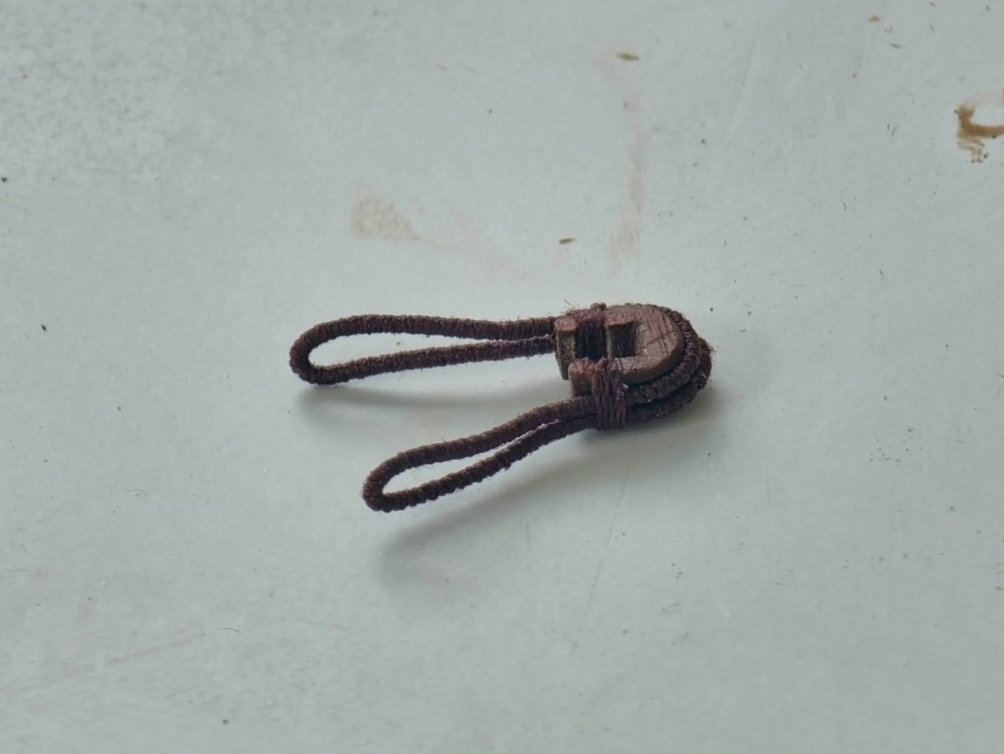
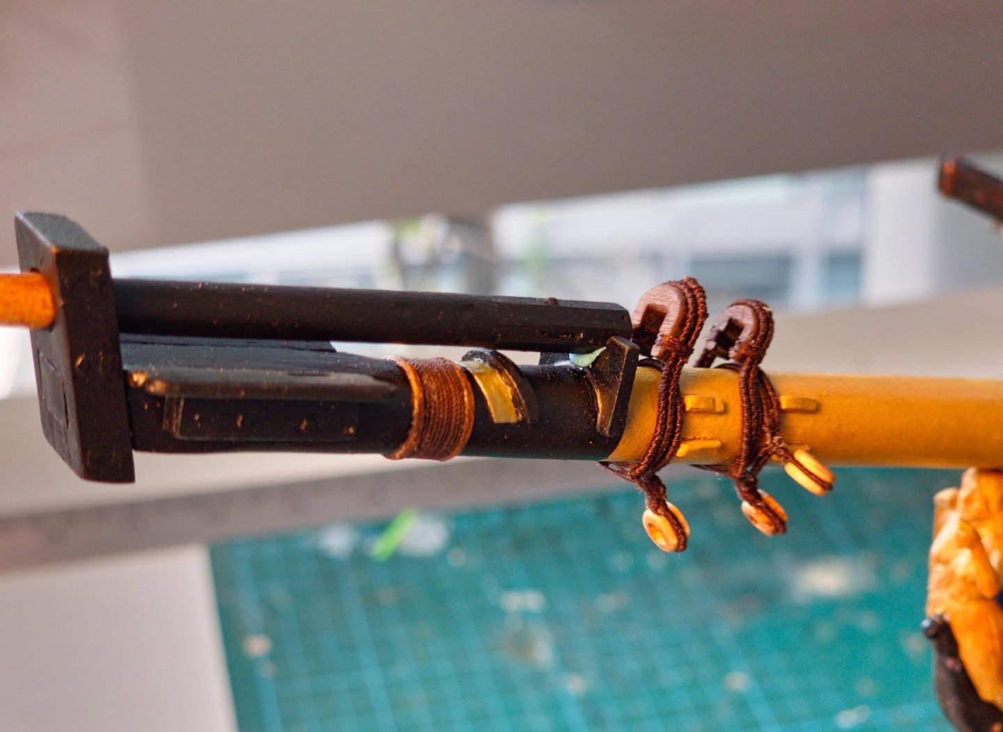
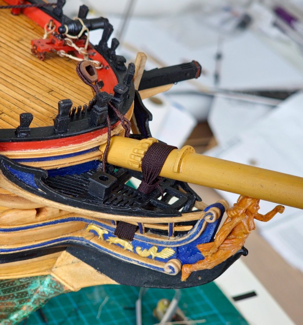
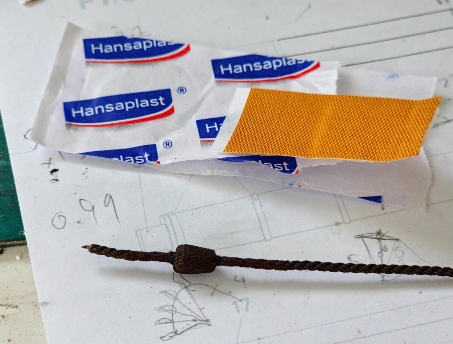
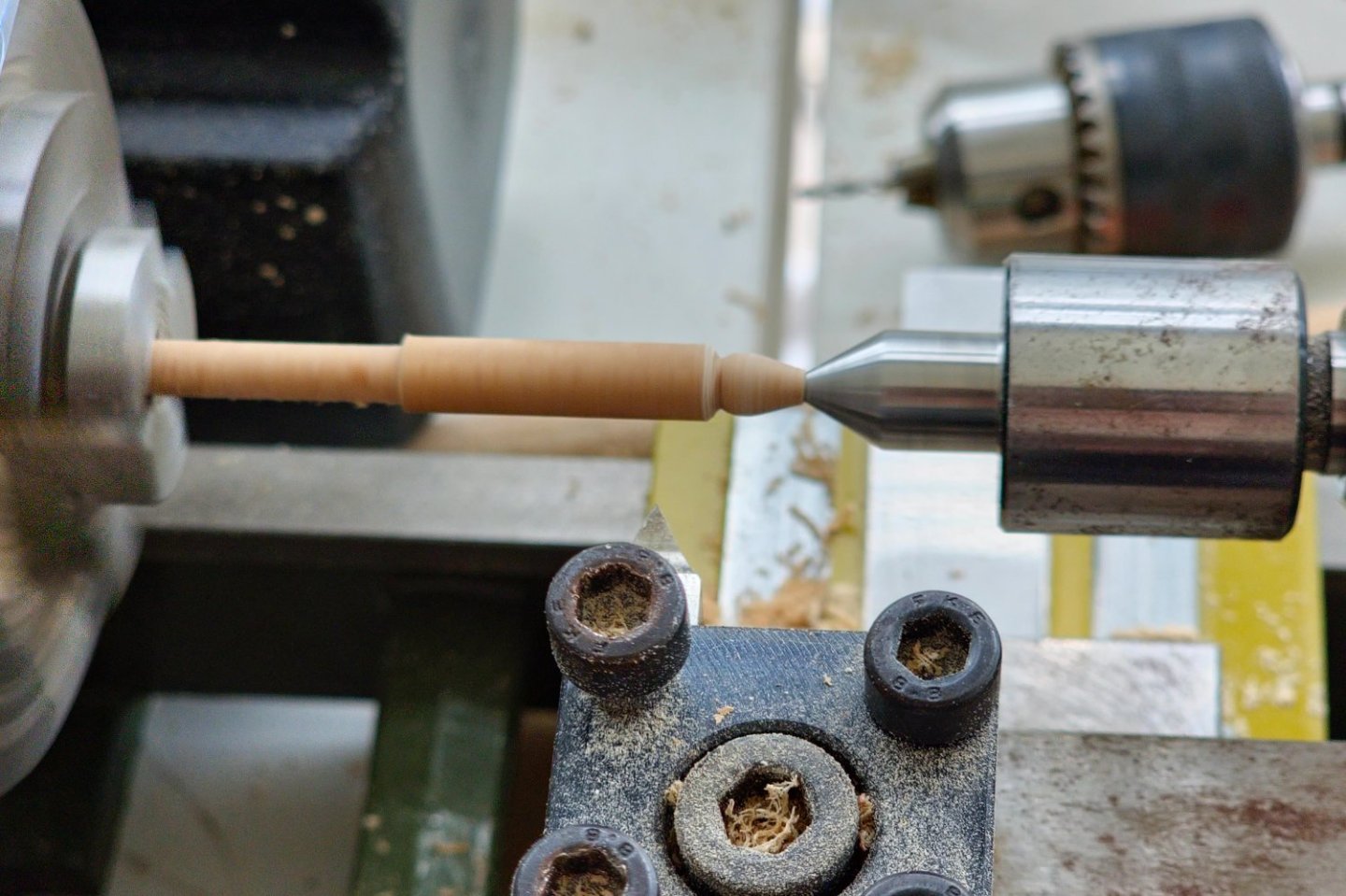
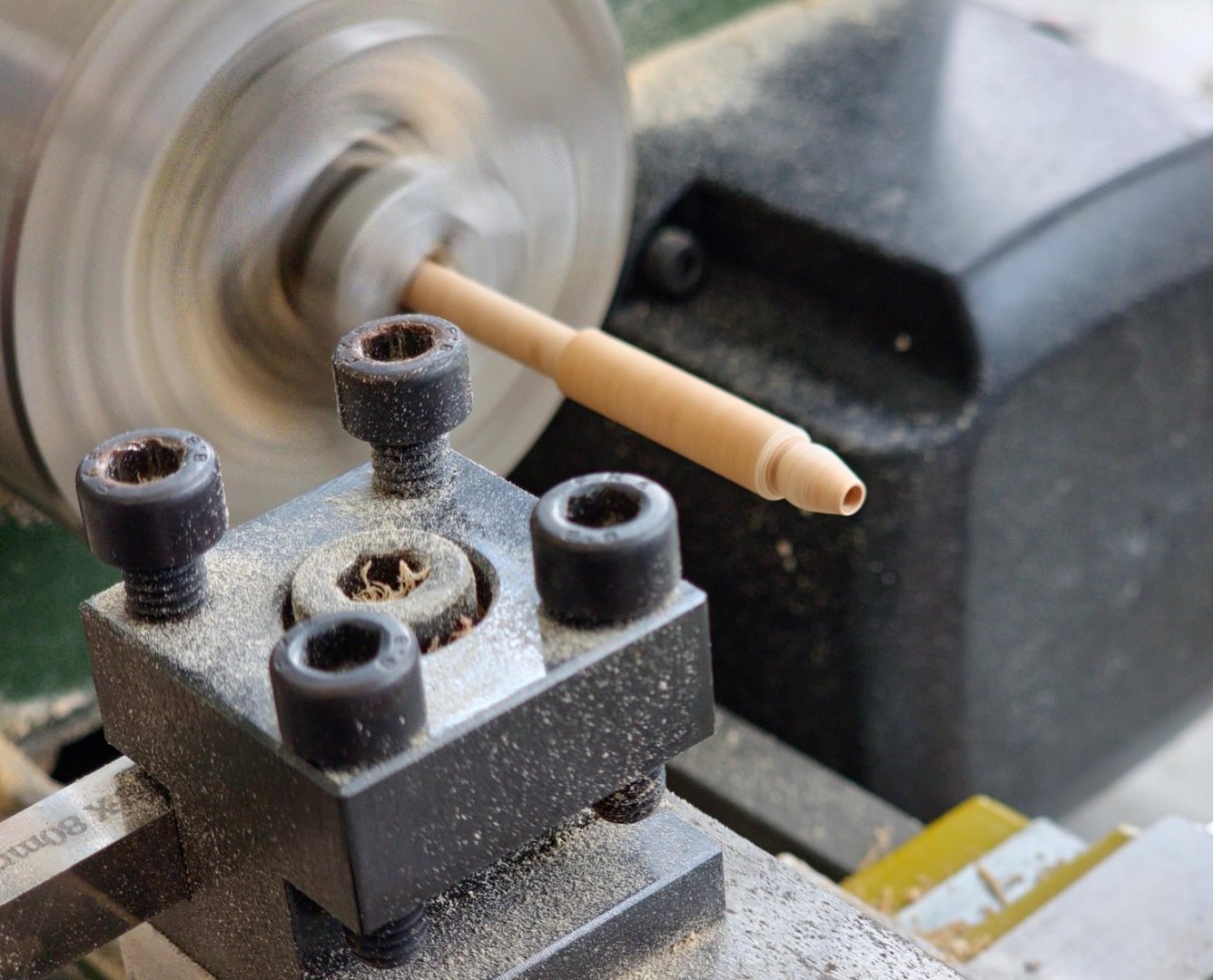
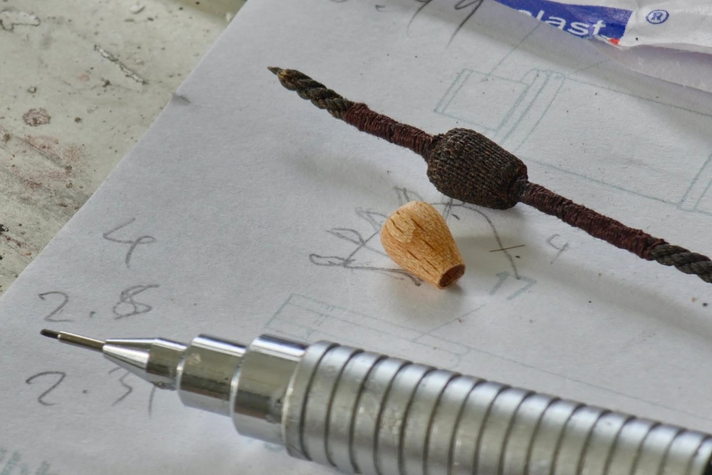
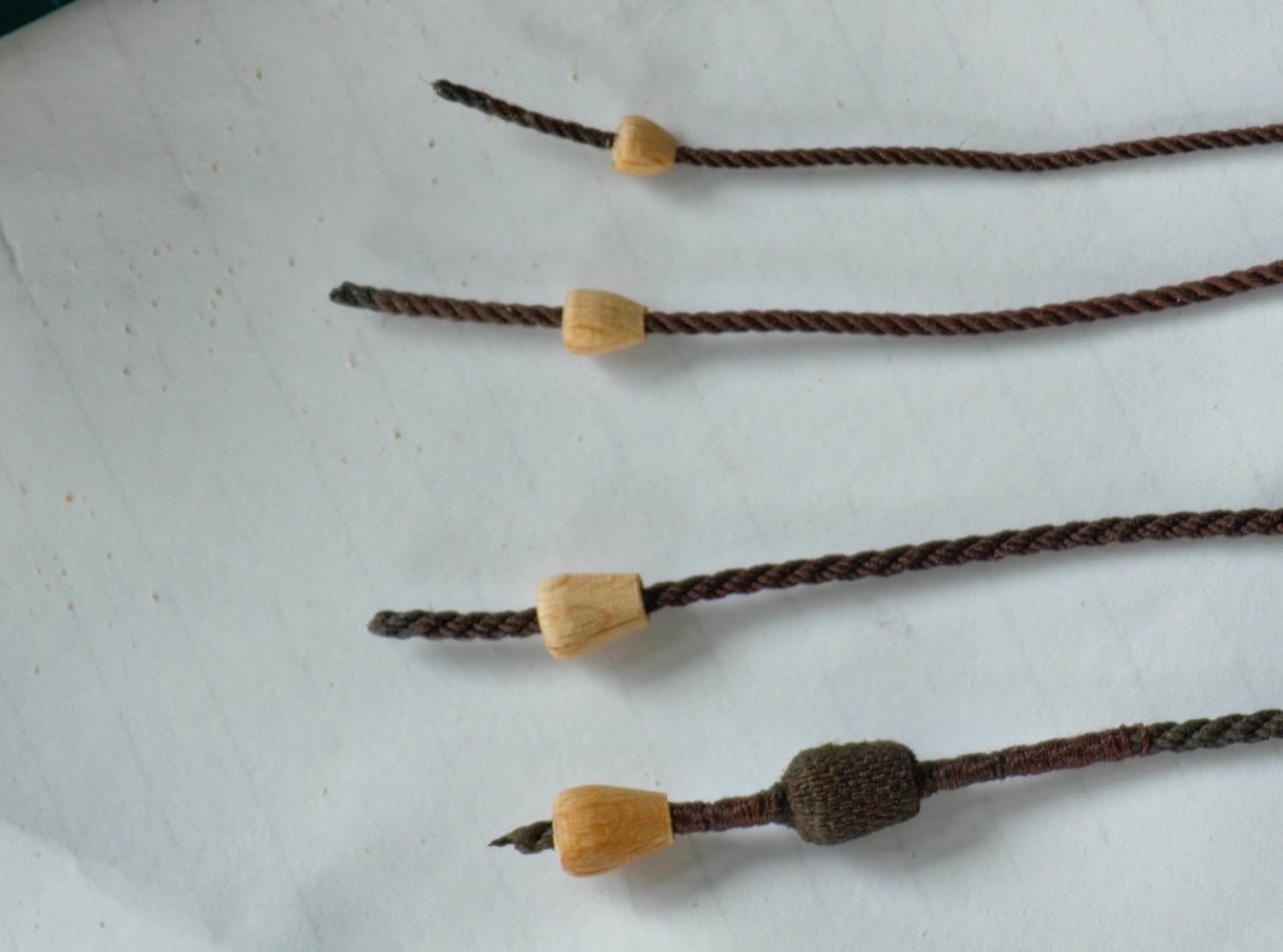
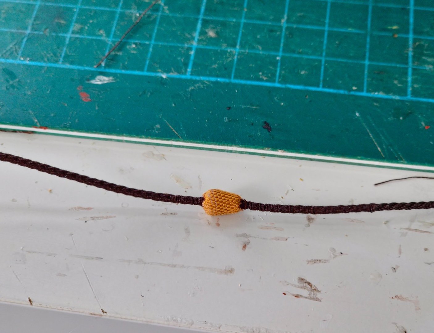
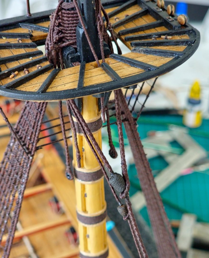
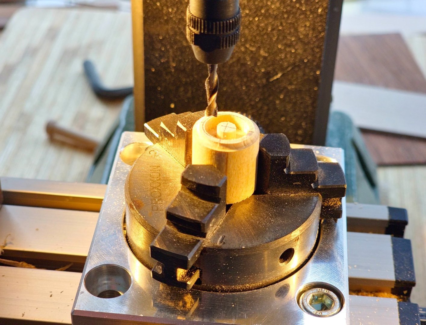
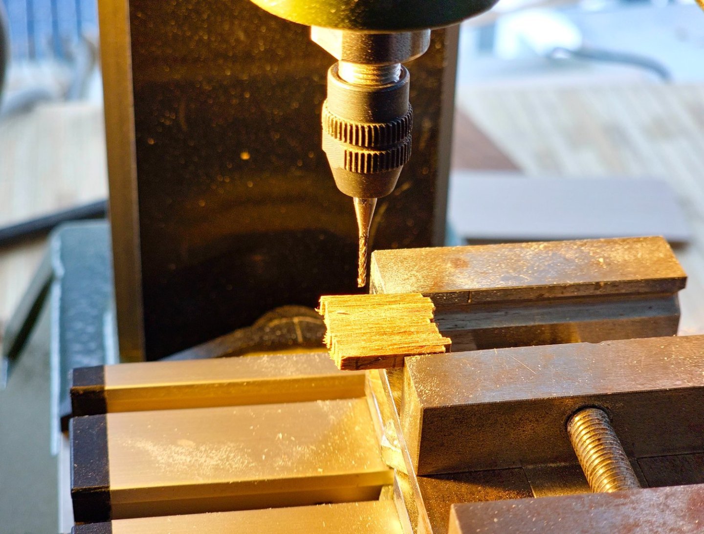
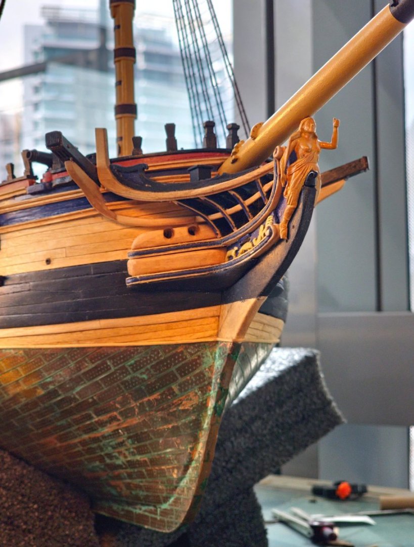
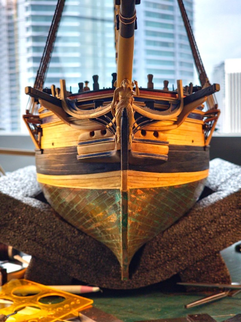
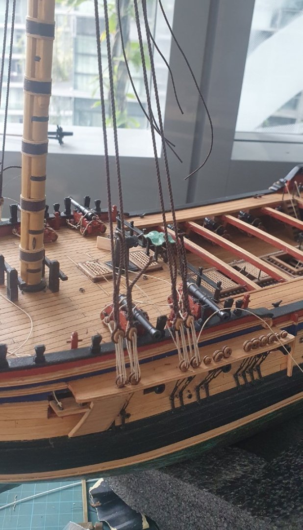
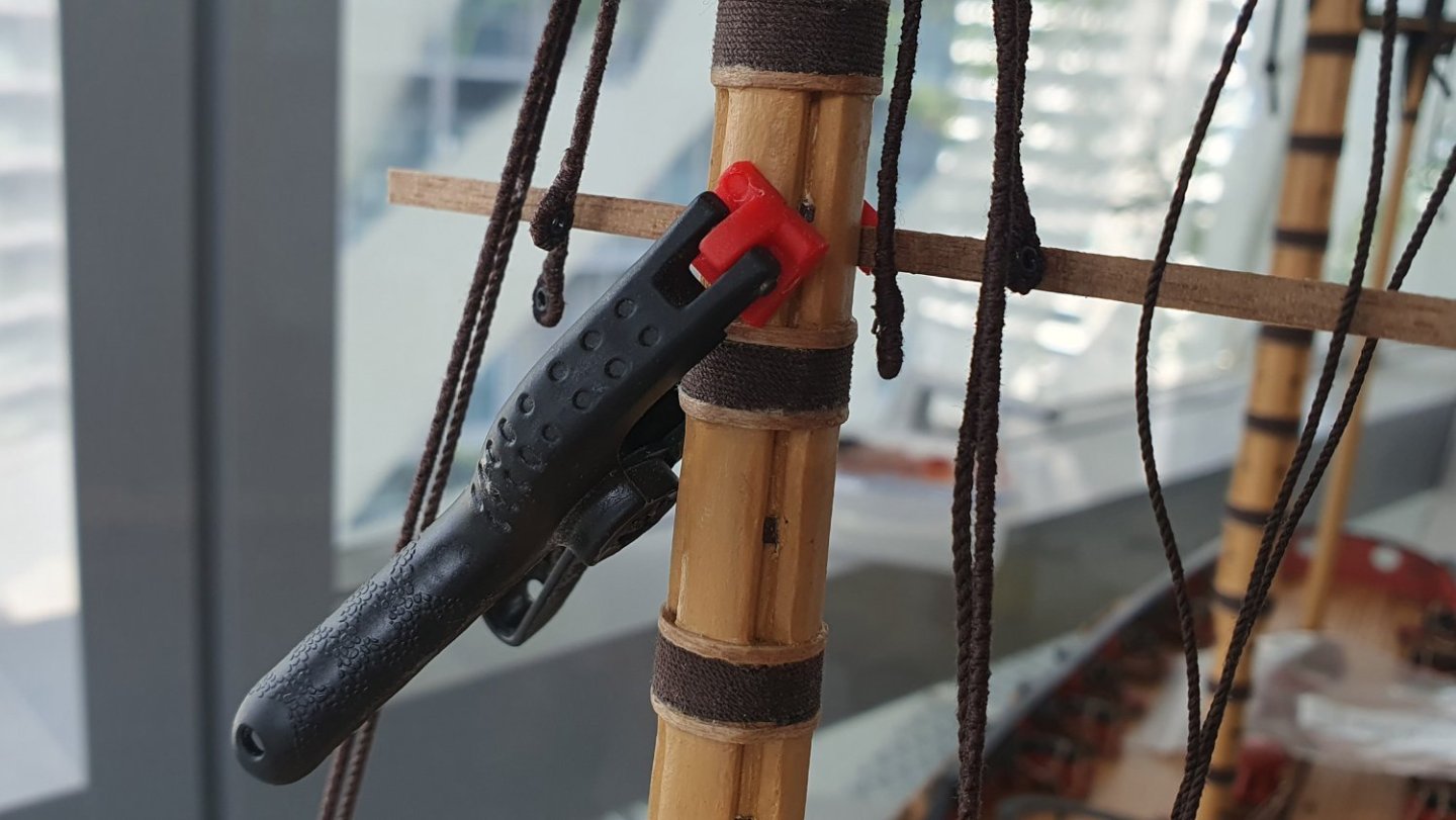
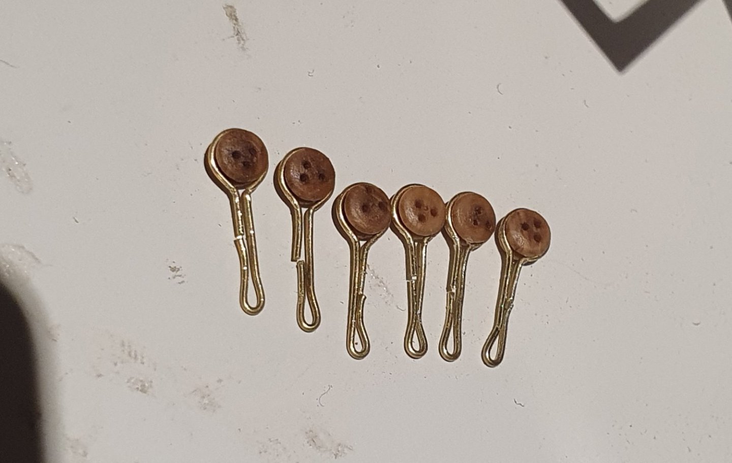
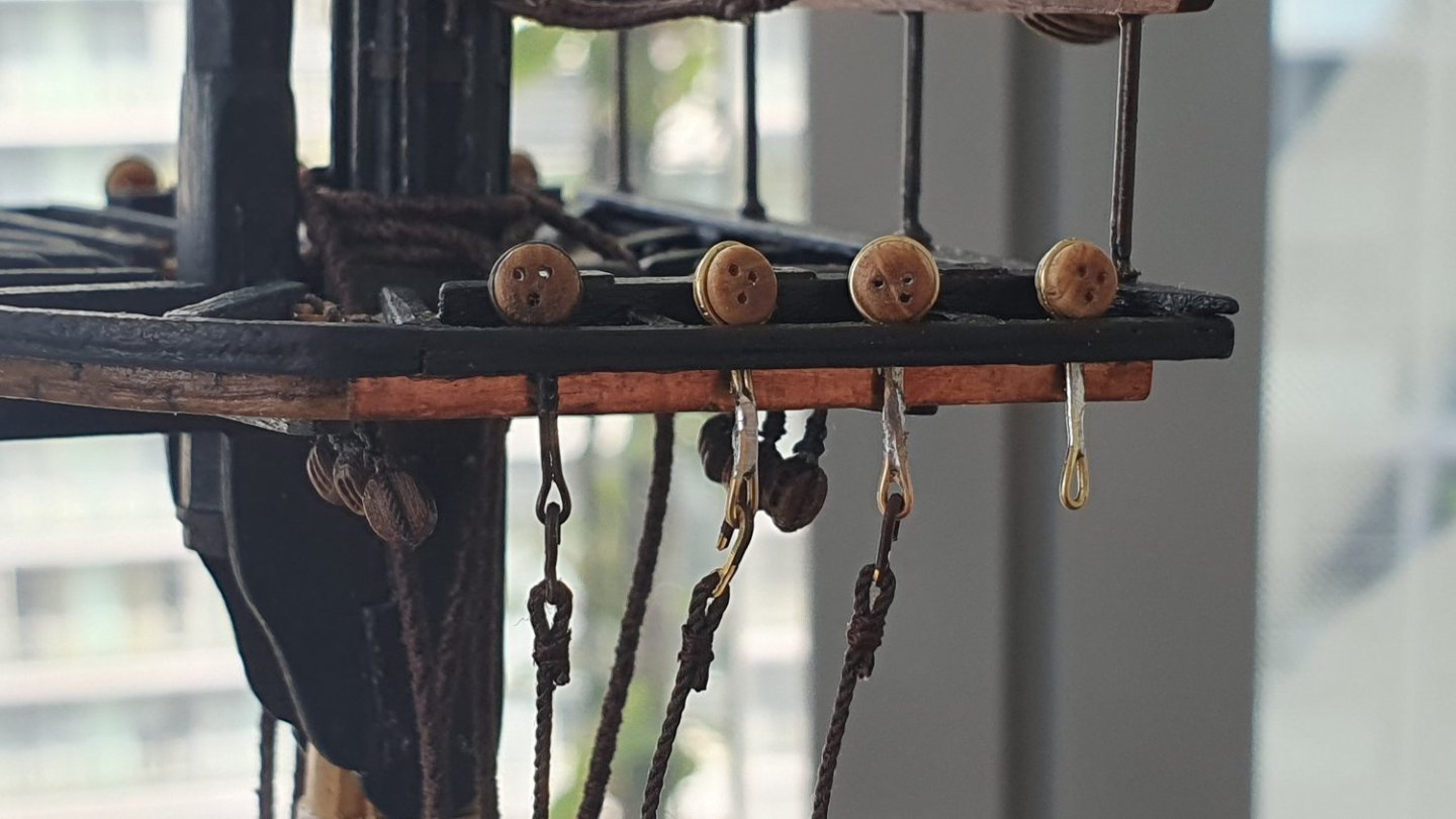
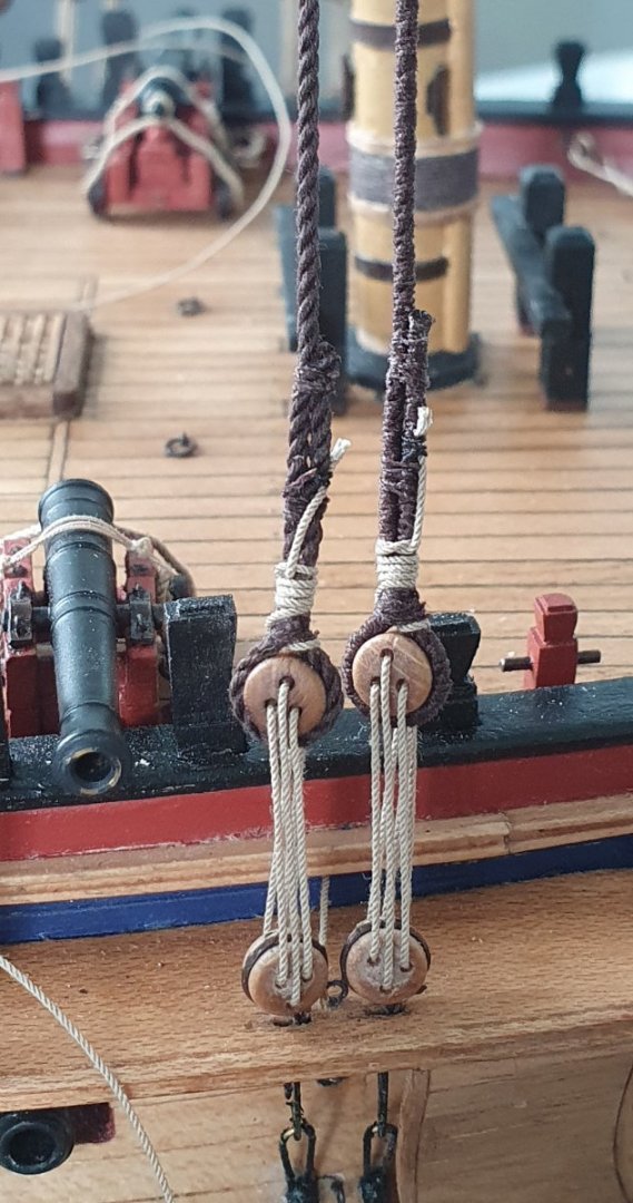
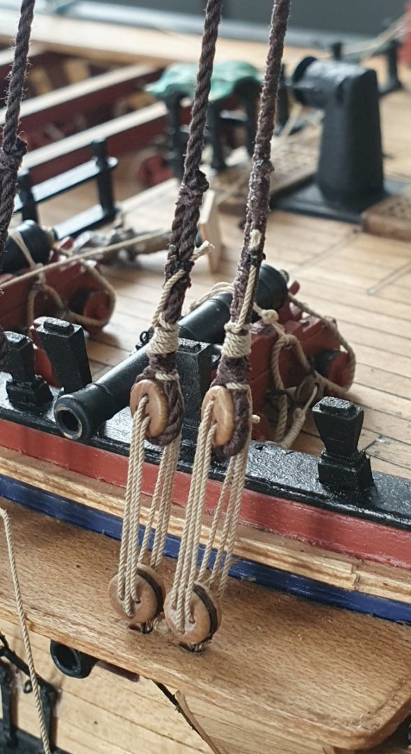
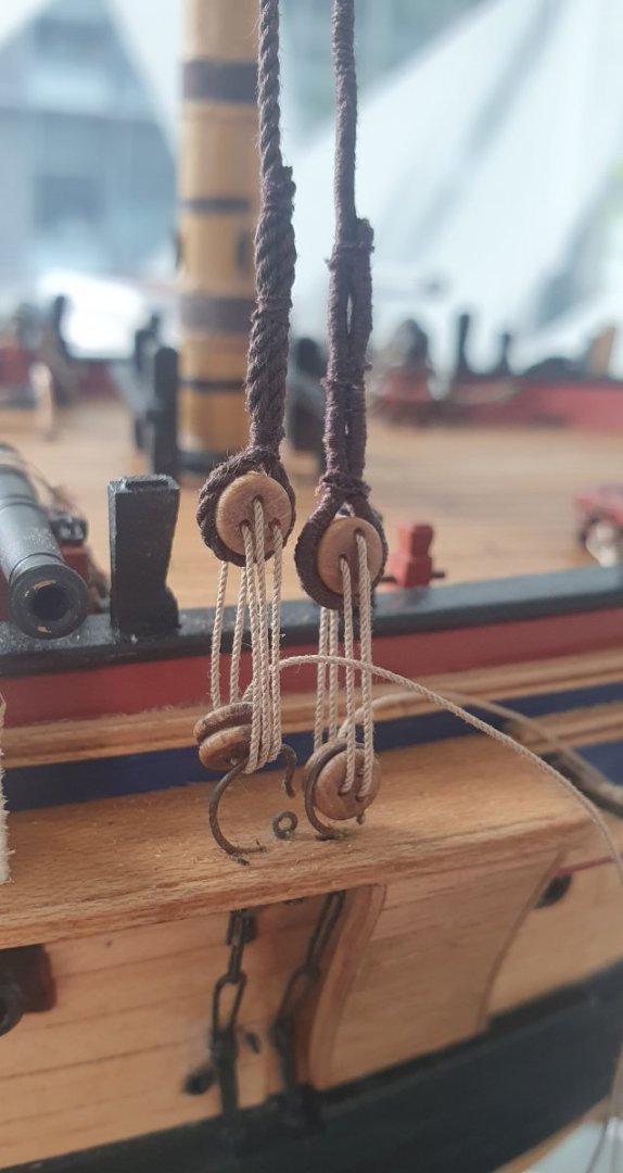
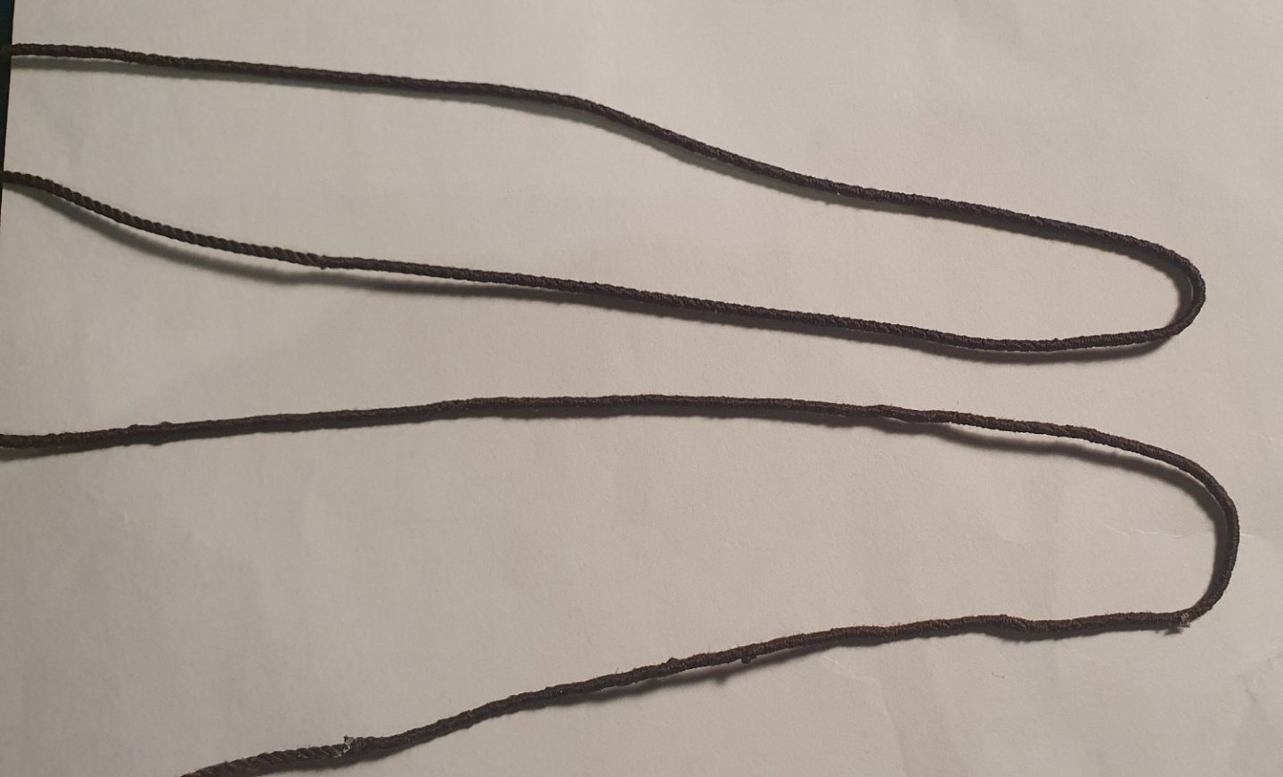
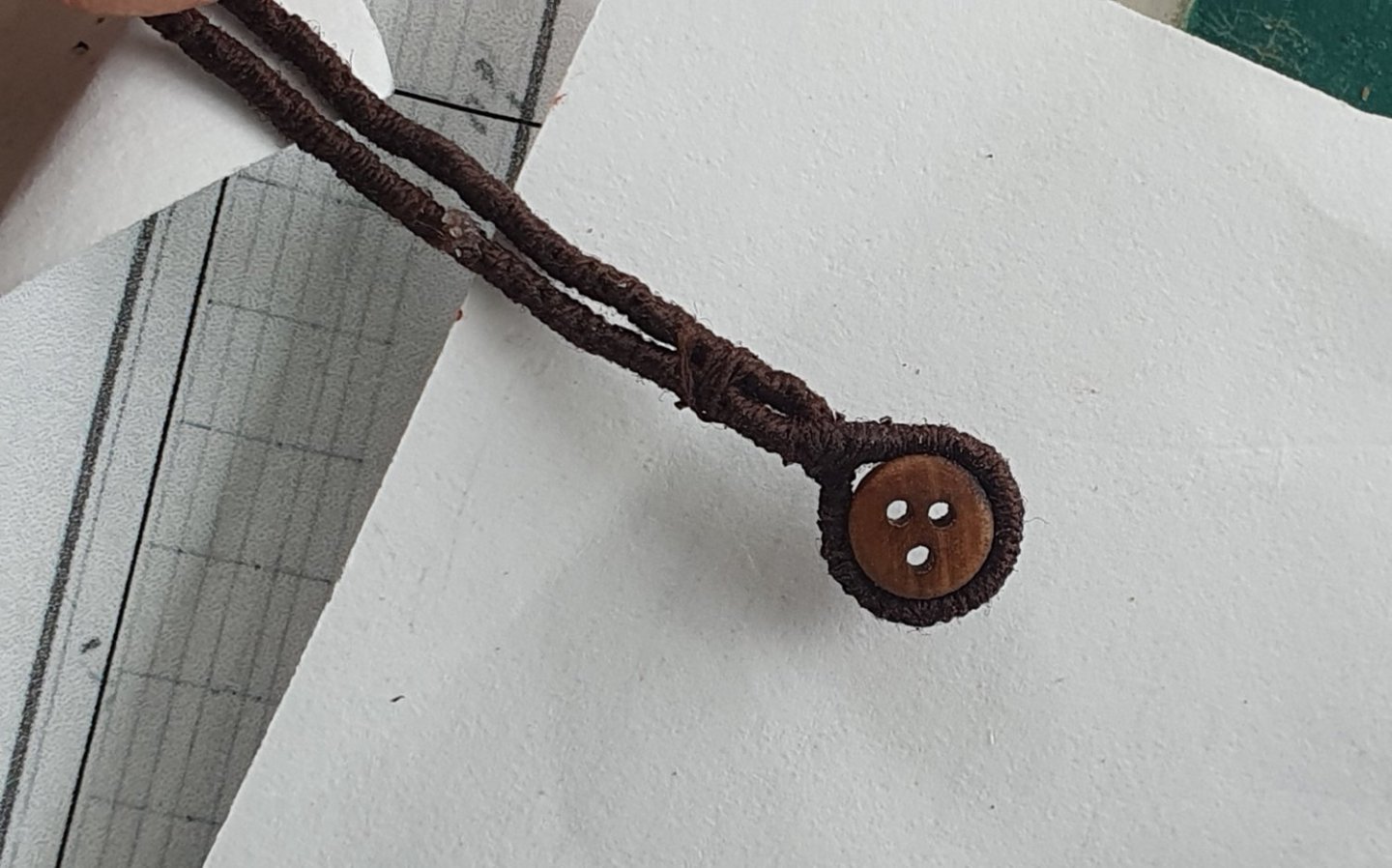
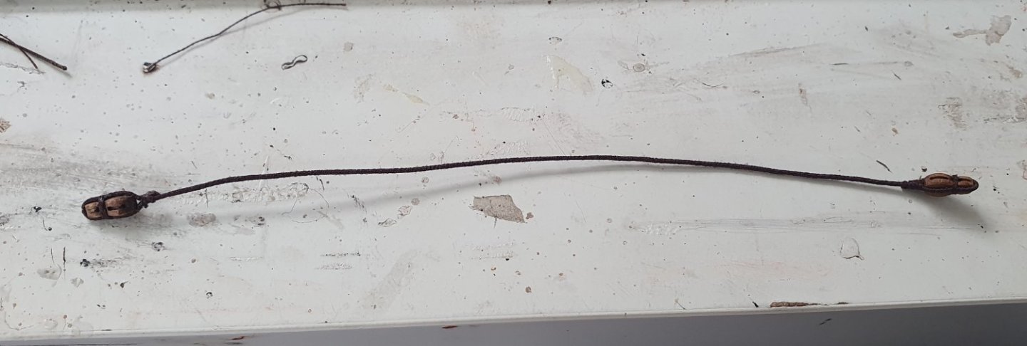
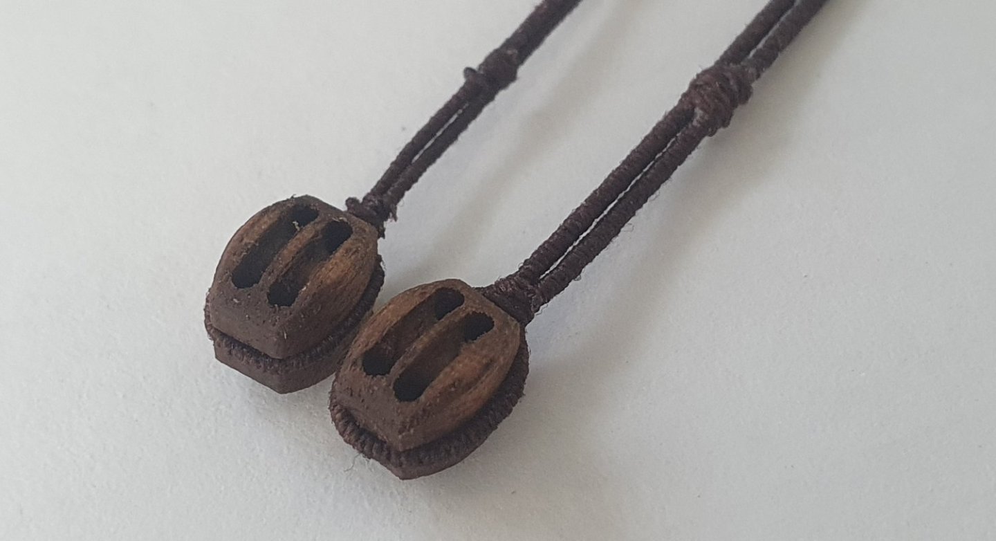
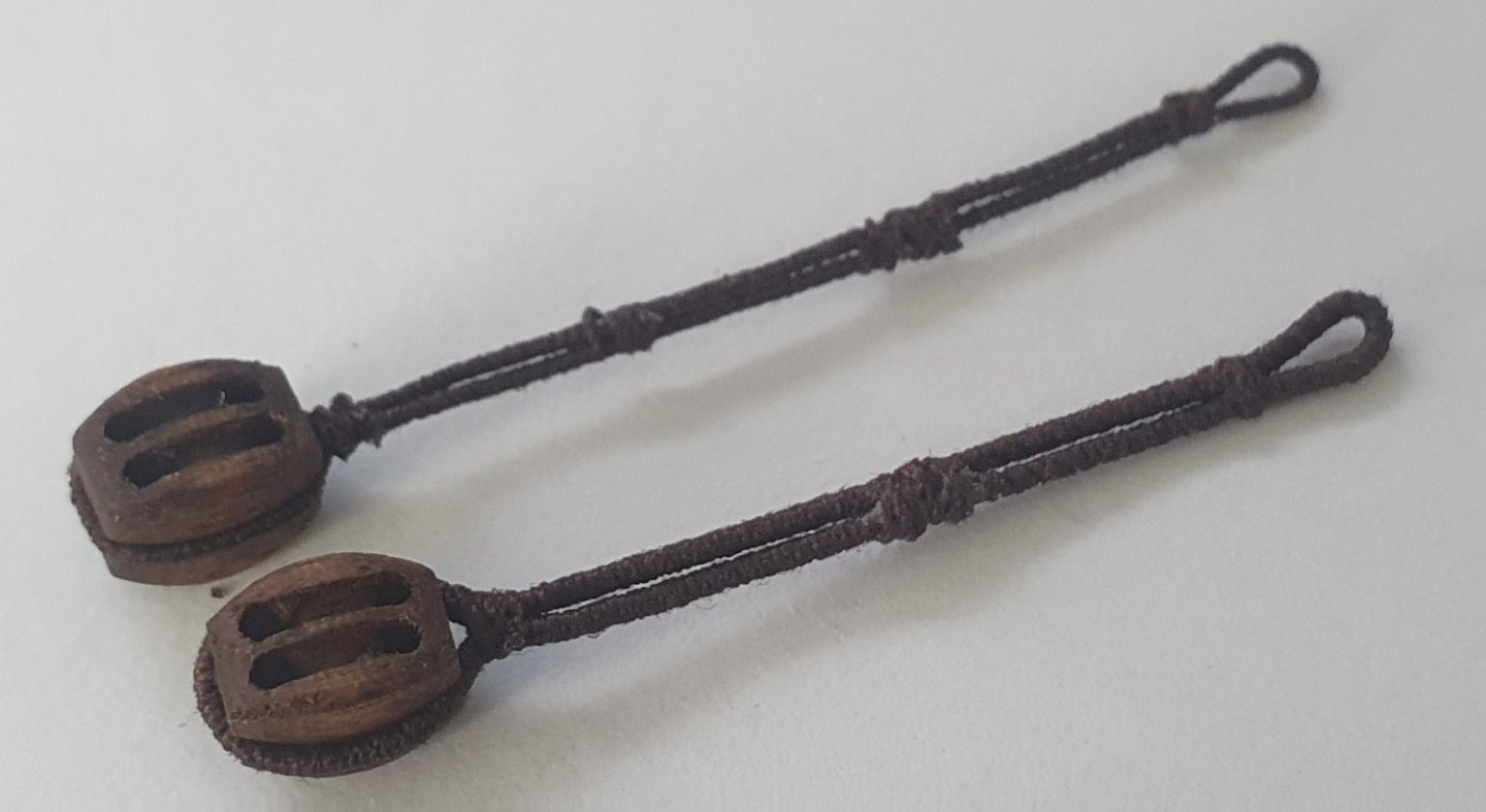
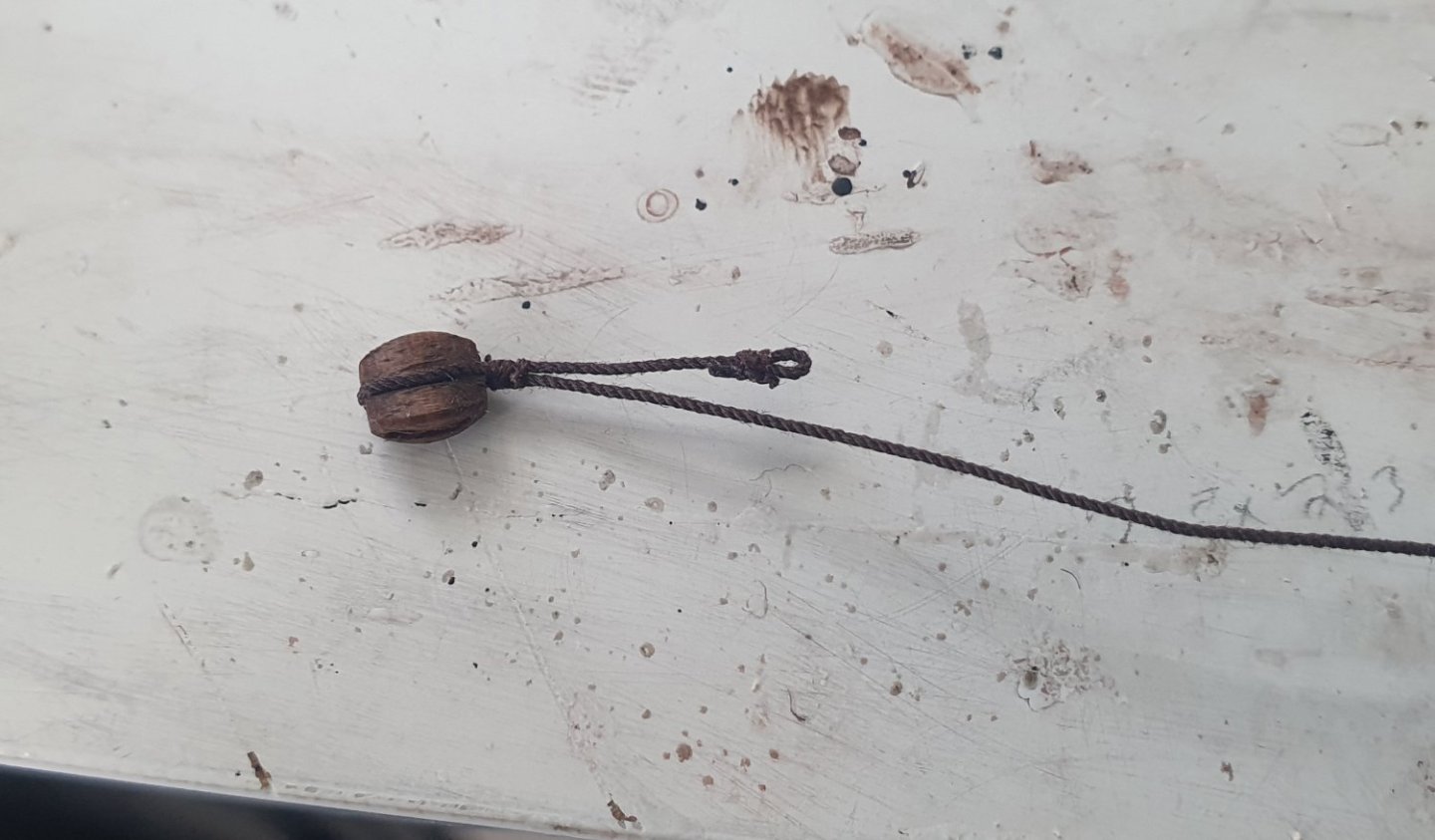
Now that the bowsprit was positioned, I began to look at the rigging for the stays to the fore mast. Turns out I have neglected to include a slew of thumb cleats that keep the collars in place. To be fair they are not that well highlighted in the documentation but it now means I will have to be mangling my finished paintwork to get these installed. I constructed them using the same method as the gammoning cleats and again milled slots in the bowsprit to locate them. I did some research into how the stays were rigged and turns out it is quite a complicated exercise. I realised that I had made a strategic mistake in not ordering replacement heart blocks when I upgraded the rest of the blocks. The kit supplied items seemed quite OK at first glance but looking in Lees these seem to be from a slightly earlier time frame than the Diana and the fore and fore preventer stays appear to be rigged with a combination of open and closed heart blocks. The Vanguard blocks look like a good offering but I have been experiencing delays with the UK postal service of late so I foolishly decided to have a go making my own as I did not have the patience to wait for a delivery and I thought there were only 6 of these. Steel indicates a different size block for each of the four stays scaling to 7.6mm, 6.7mm, 5.5mm and 4.7mm but the smaller sizes were too challenging for my clumsy hands so I rationalised them into two sizes (big and small) and exaggerated the dimensions slightly to give me a fighting chance (9mm and 7mm). I based these on the drawings in Lees but the end results are a bit agricultural however I was able to get a double groove in the open hearts to accommodate the collar configuration. Once they are festooned with rigging, they should be fairly anonymous. I used the first of these in the collar for the main stay. For this I served a 1mm diameter rope. It should be a little bit larger but I had drilled the hole in the gammoning knee a very long time ago and it is no longer accessible to make larger. It was not that easy getting the rope in there to be sure. I thought it would be wise to install as much rigging as I could on the bowsprit before I fixed it in place. The bobstays were the first to go on and first dilemma. I suspect that these should be closed hearts but deadeyes seem to be an acceptable alternative. After having made the initial batch of hearts I was loathe to have to make a whole lot more especially as these are 3.5mm in size which is smaller than I dare attempt. Still, despite swearing that I would not make these I ended up having a go anyway. I used some dowel that was lathed down to 5mm in diameter. I then drilled a hole down the centre. I then lathed a series of grooves at 1.25mm centres which would give me a 2.5mm thick block with a centre channel. The final shape was milled out and then finished off by file. The result was not the best and I had a high failure rate due to the relatively large grain of the beech dowel. I really needed a different timber type to be able to make these successfully. I noticed that the ones on HMS Victory look almost circular in shape so I thought that drilling out a deadeye might make an acceptable compromise. These deadeyes are boxwood so much more robust when working at the small scale. I also decided to mix it up and use deadeyes for the bowsprit shrouds. I think that the deadeyes will also be easier to rig. Installing these blocks onto the bowsprit was harder than anticipated. I decided to use served rope as per Lees which further complicated matters. I had a real problem. getting the length of served rope correct and managing to seize the blocks as close as possible to the bowsprit. Trying to produce the double served rope that holds the open hearts in place was a real low point. Time to fit the bowsprit permanently. I had seen some very neat gammoning before but that was beyond my skill level. I used 0.8mm rope and despite several attempts I was unable to achieve the elegant spiral depicted in Lees. In anticipation of fitting the stays, I had a go at making a mouse. I could not find much information regarding the size but scaling off the drawing in Lees I came up with a proportional formula where it appears that the largest diameter should be around three times the diameter of the stay with the length three and a bit times the diameter. Which I have just realised could be Pi and the length is equal to the circumference of the stay which would be quite an elegant formula if true. I inserted some beech dowel into the lathe and carved the mouse out freehand using a file. I then covered this using some sticking plaster to get the woven pattern which was painted with an ink mixture that tried to mimic the dark brown colour of the stay. Quite a performance given the waterproof properties of the sticking plaster. My first effort looked a bit odd but I subsequently read in Steel that the mouse should be shaped like a pear and not like the black pudding I ended up with. I decided to have another go where I reduced the diameter at the thin end to achieve a more pear like shape. Each stay is a different diameter and thus a different size mouse. Once I had the whole family of mice assembled, I positioned it on the stay and then served it in place. The fore stay was 1.65mm diameter cable and the preventer stay 1mm diameter rope. I installed the preventer below which seemed to be a modeller's choice type of decision. The colour variation of the mice seen in the photographs is not as apparent as it seems. My phone camera loves to over saturate the images. I suppose I could improve it though. I fixed the stays in place using the homemade hearts and seized them together with some 0.5mm diameter lanyard. Now that they are in place, I feel the urge to add some snaking but I am reticent as I think that it will be very difficult to achieve an acceptable end-product. I may give it a go though as I am treating the fore mast as a test bed for rigging elements.


-
Thanks for the kind words Jason but I am sure that, even if you have a bad day, your carved timber heads will make my efforts seem quite clumsy Regards, David
-
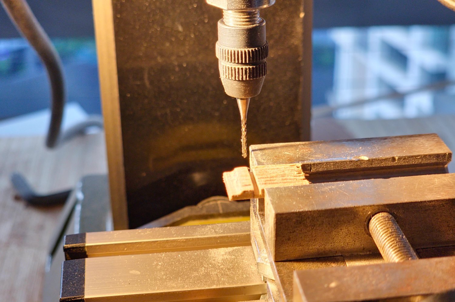
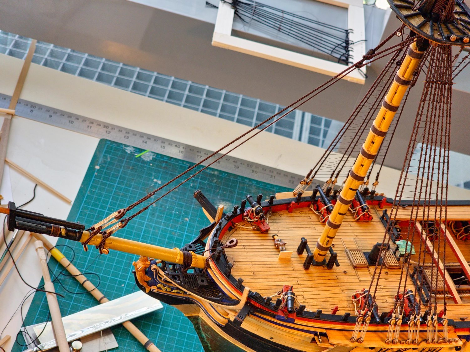
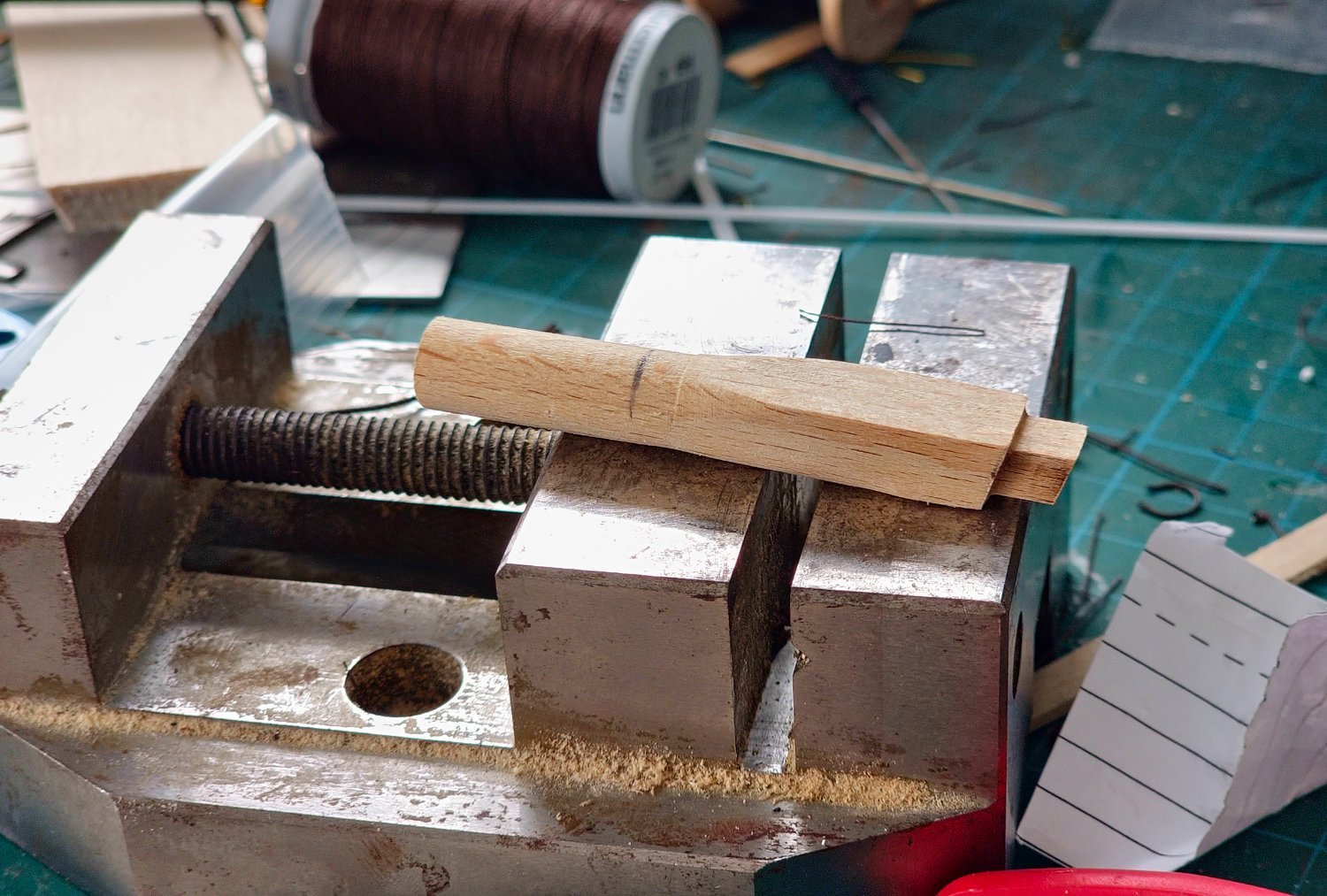
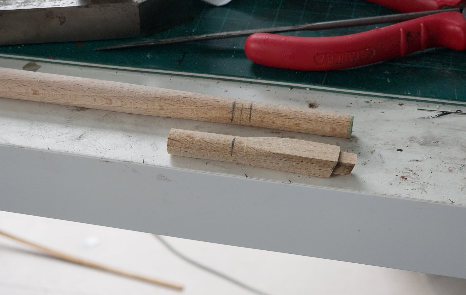
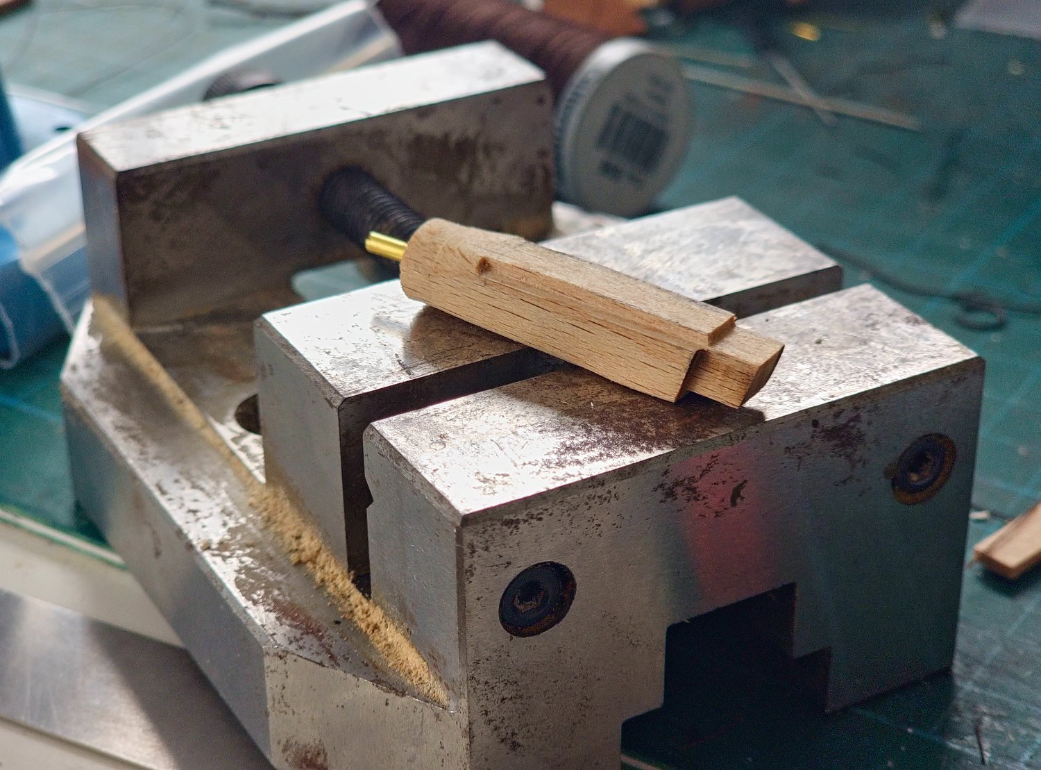
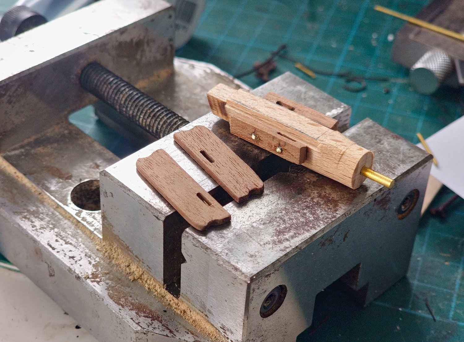
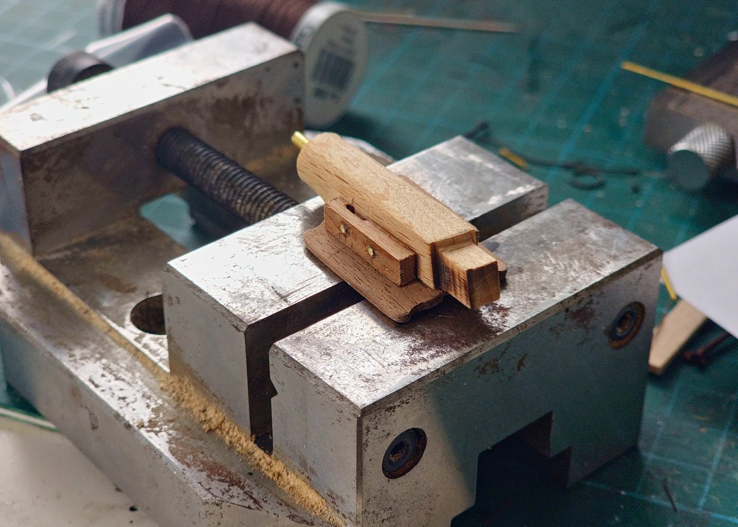
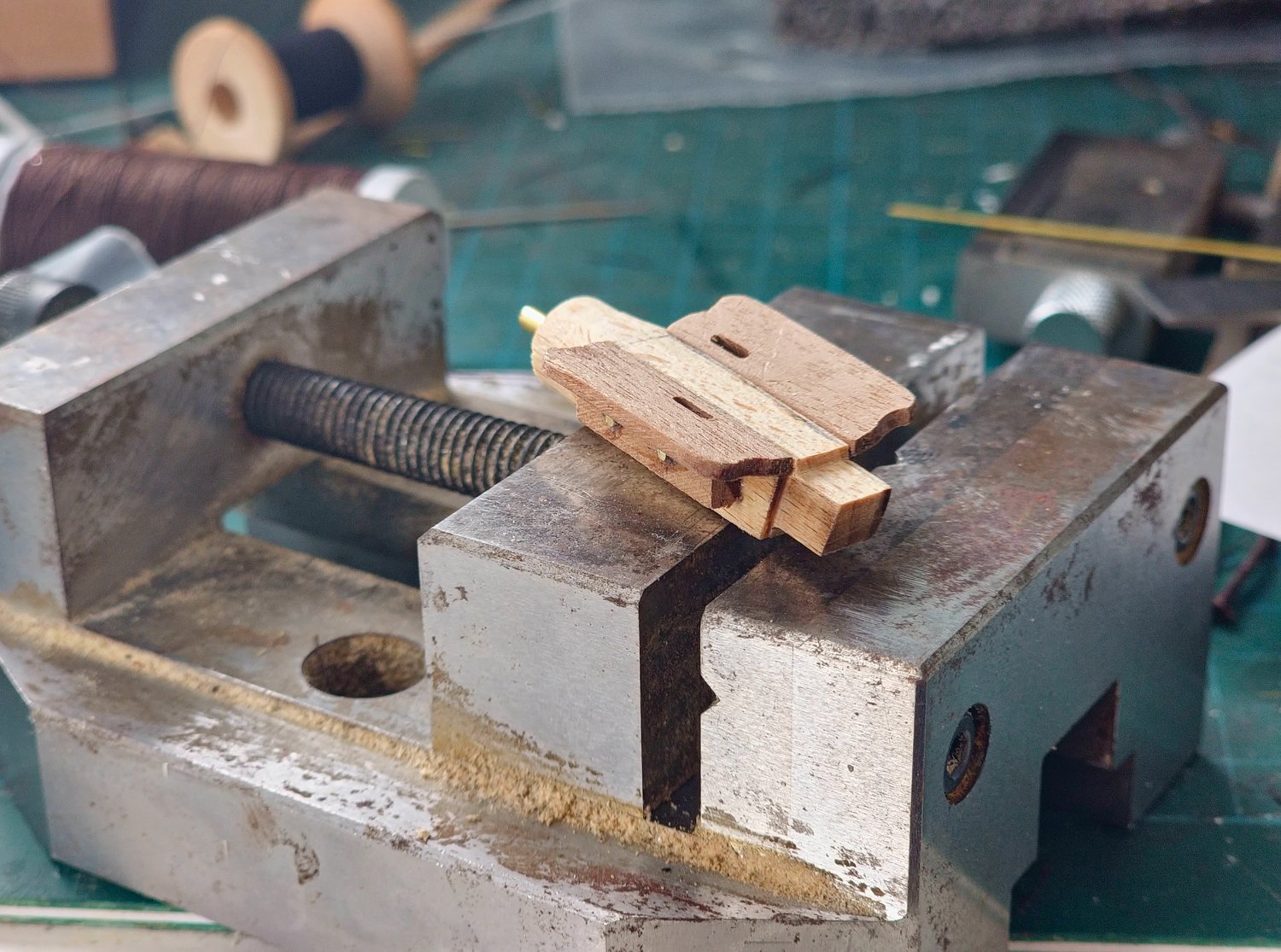
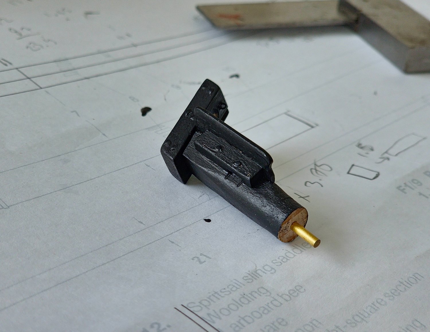
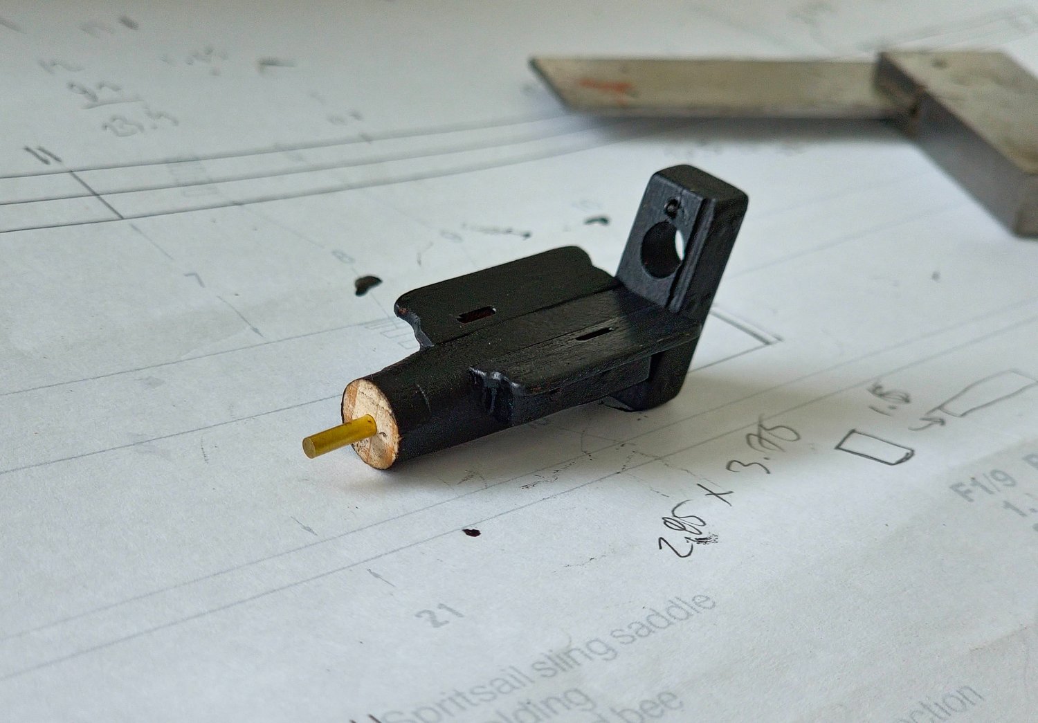
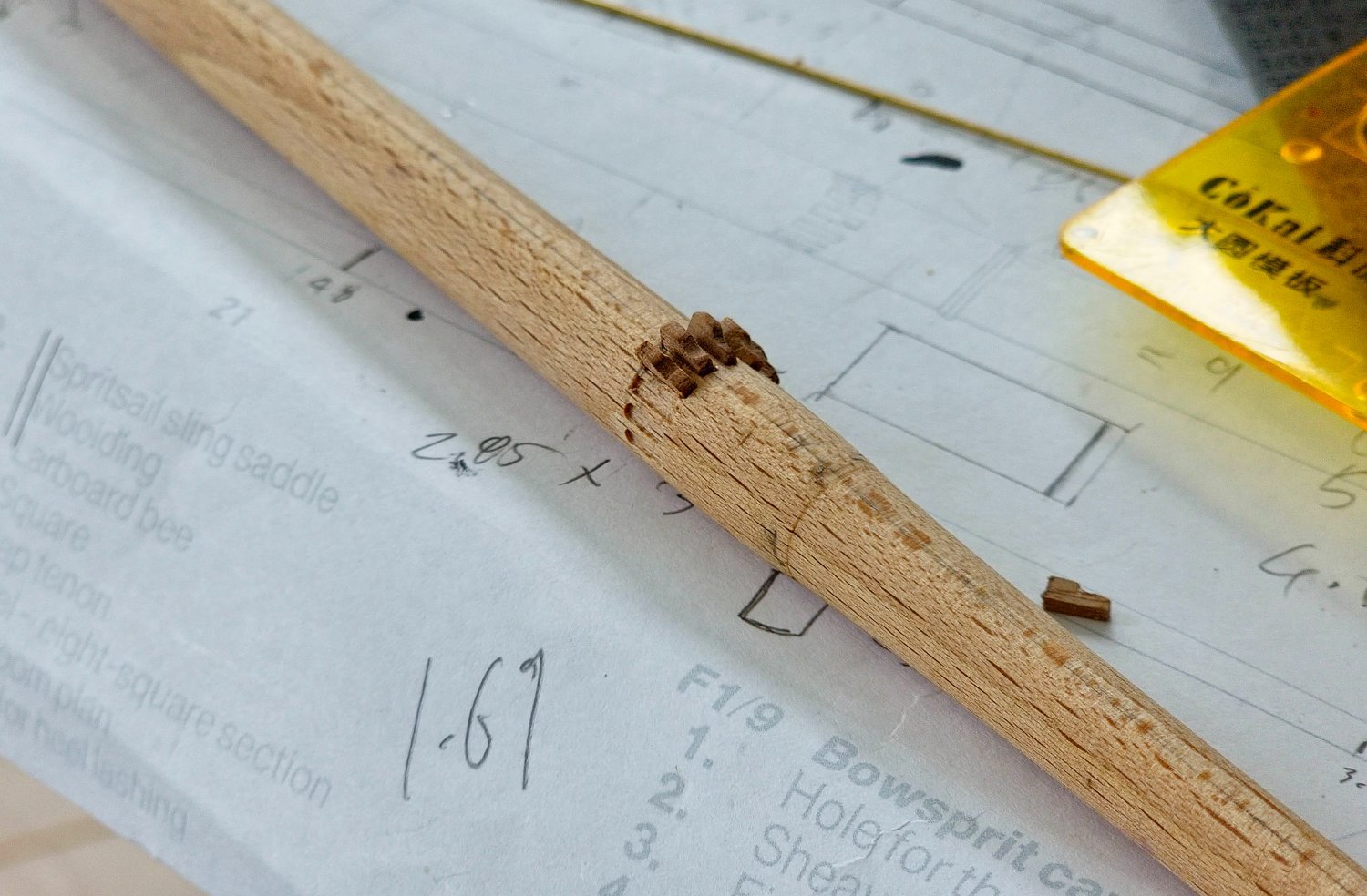
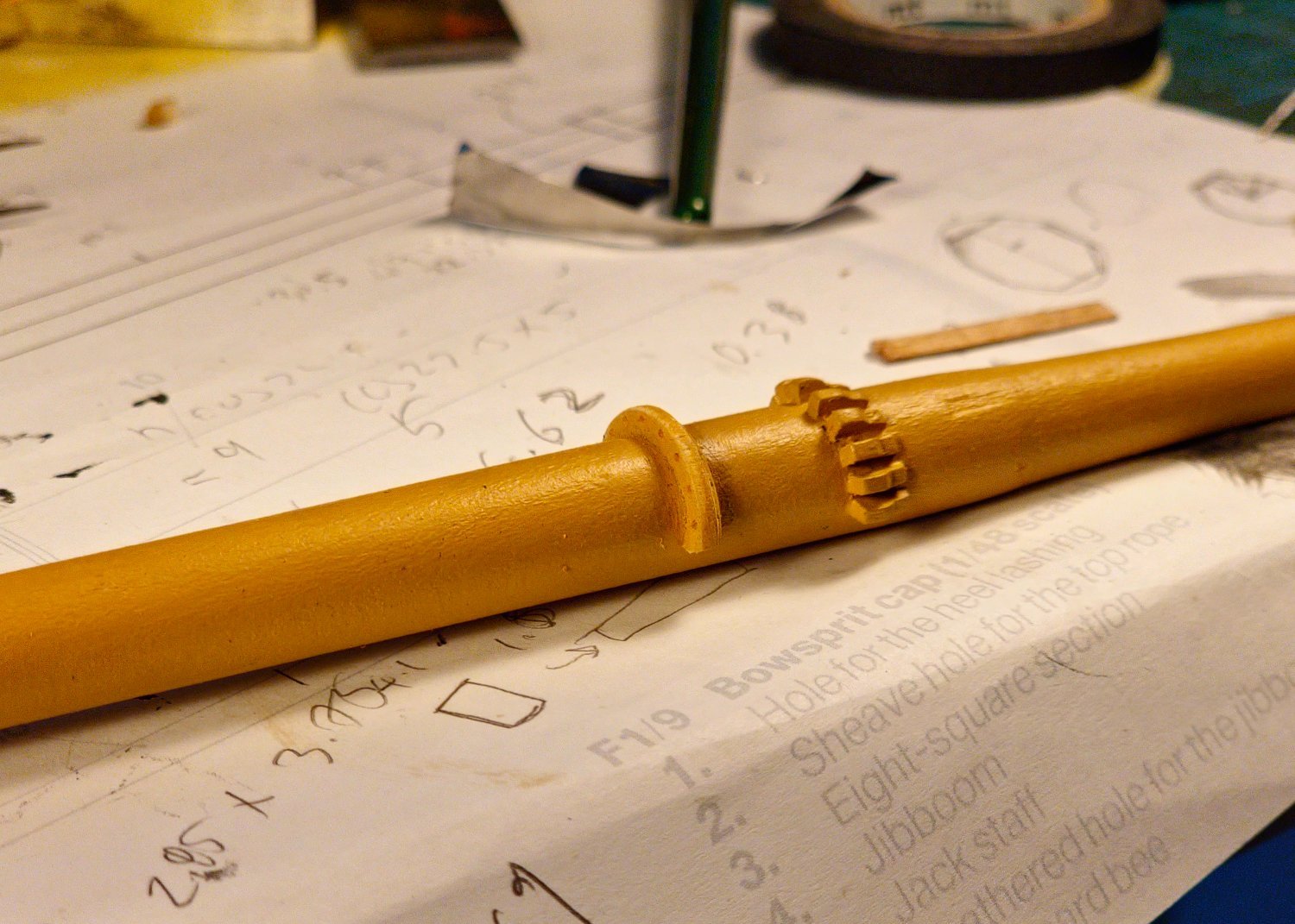
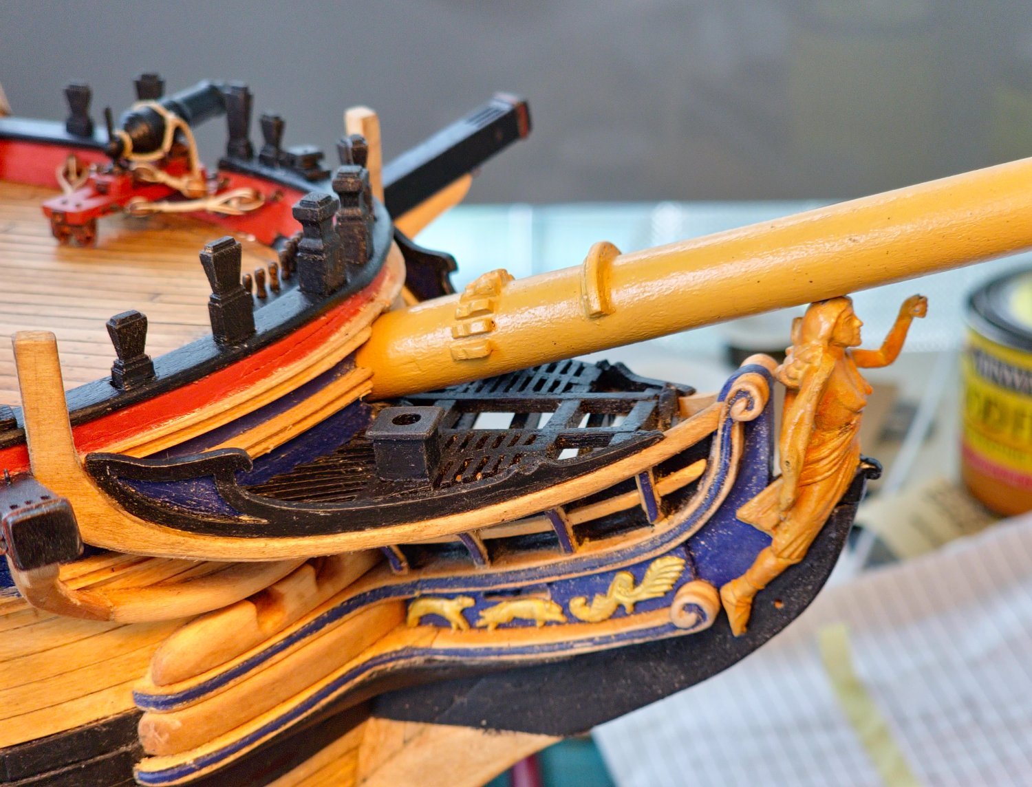
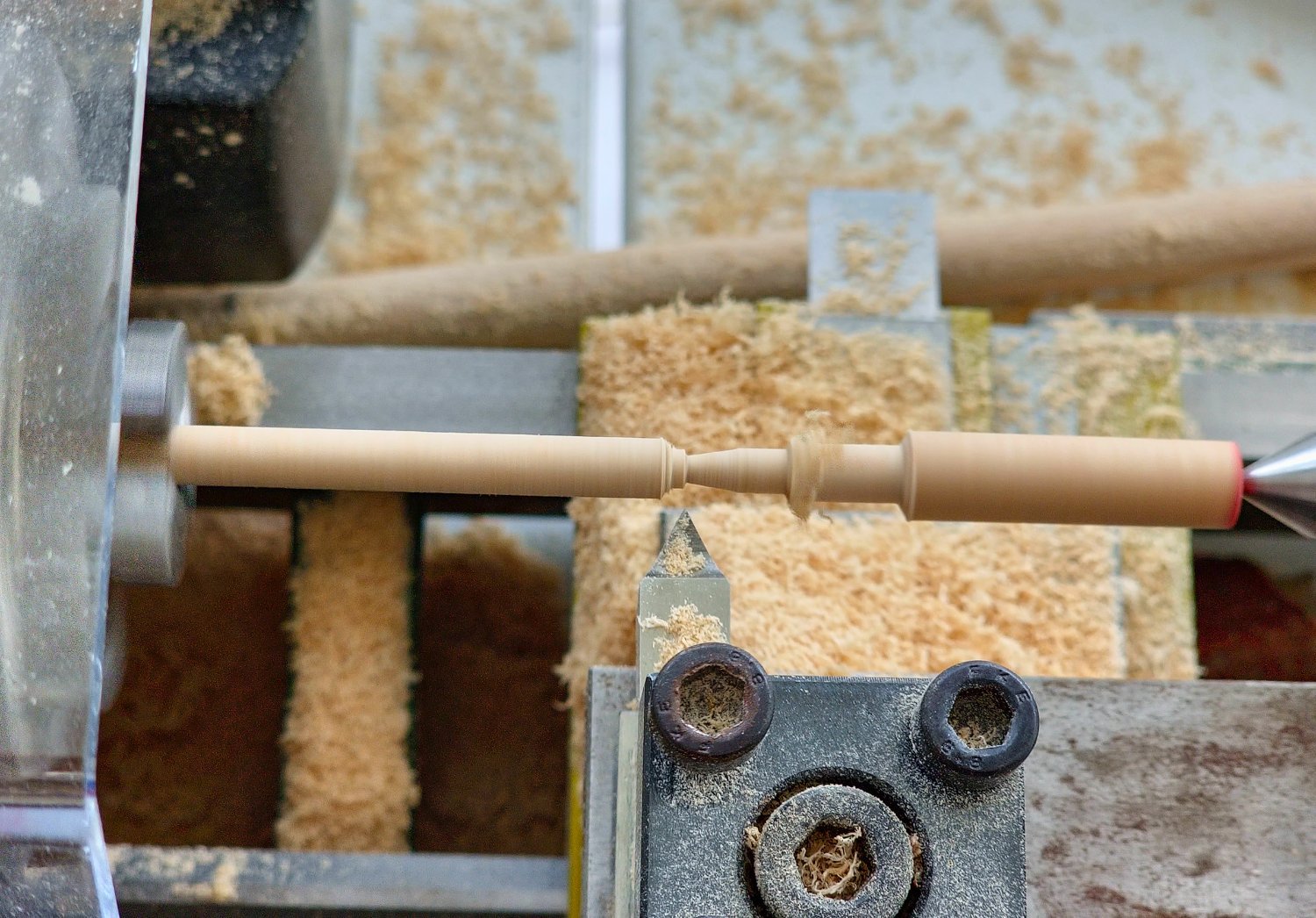
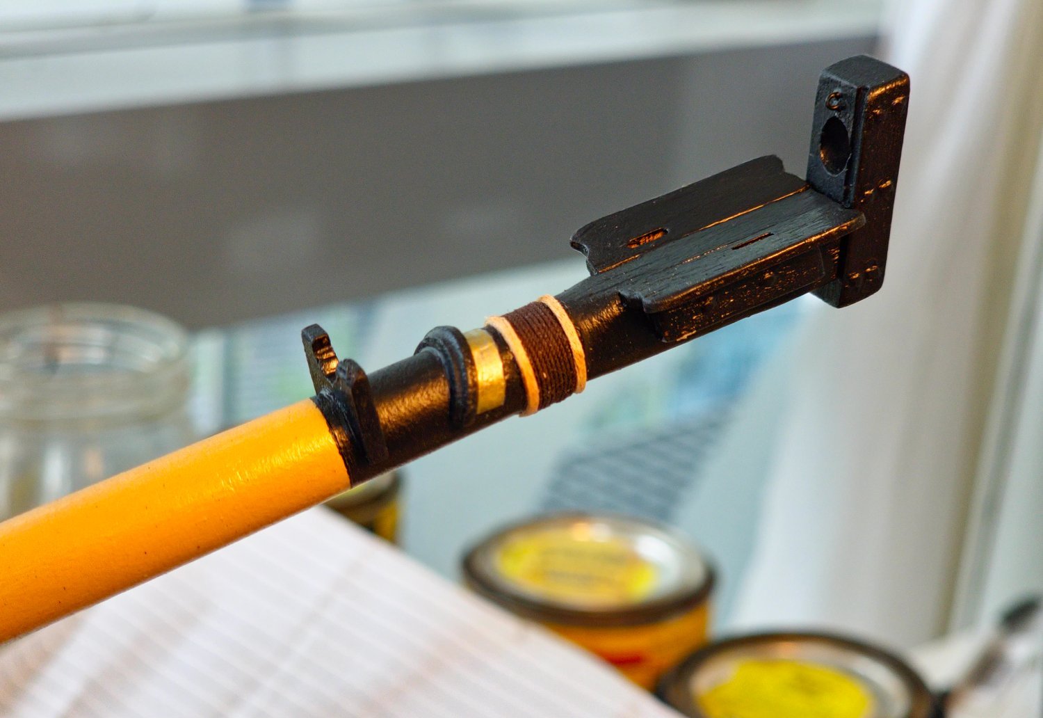
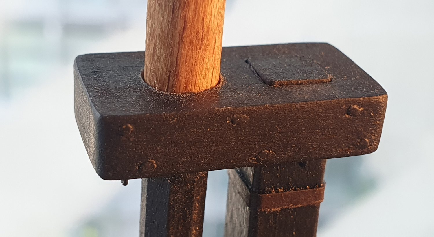
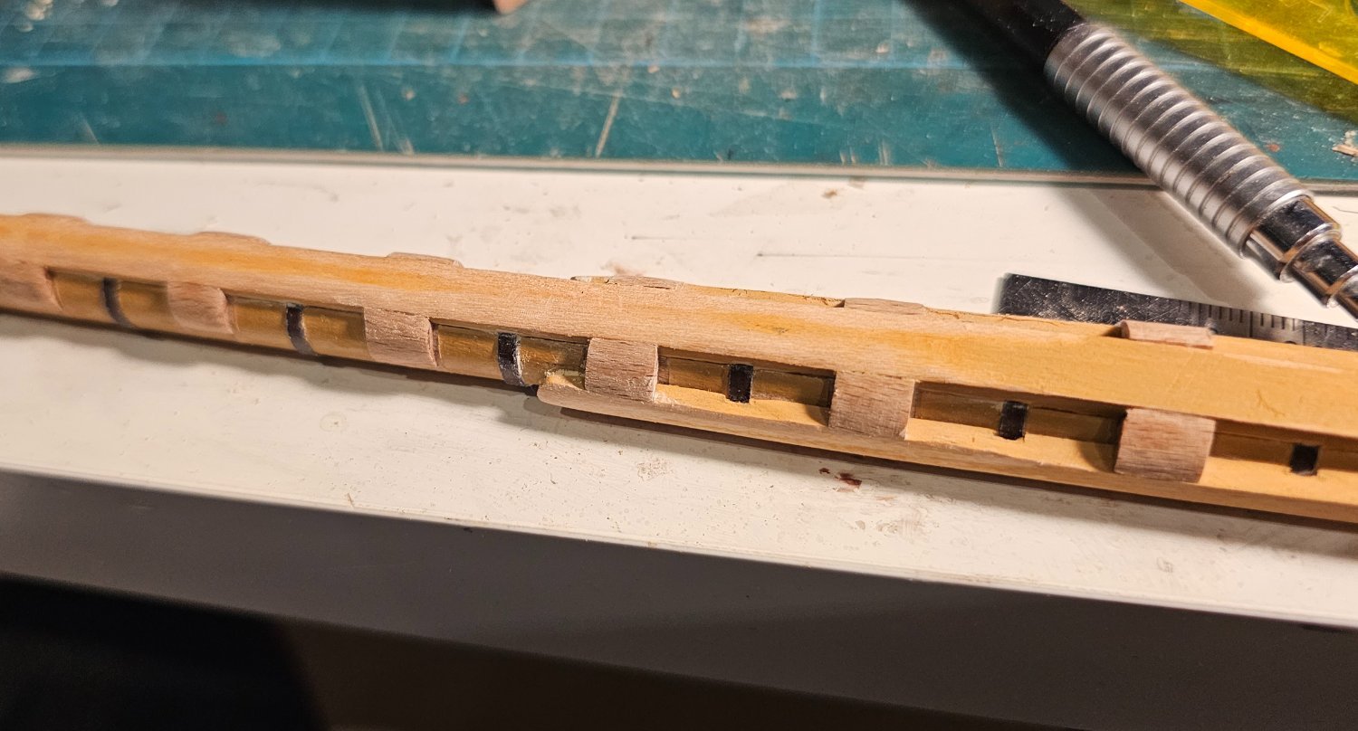
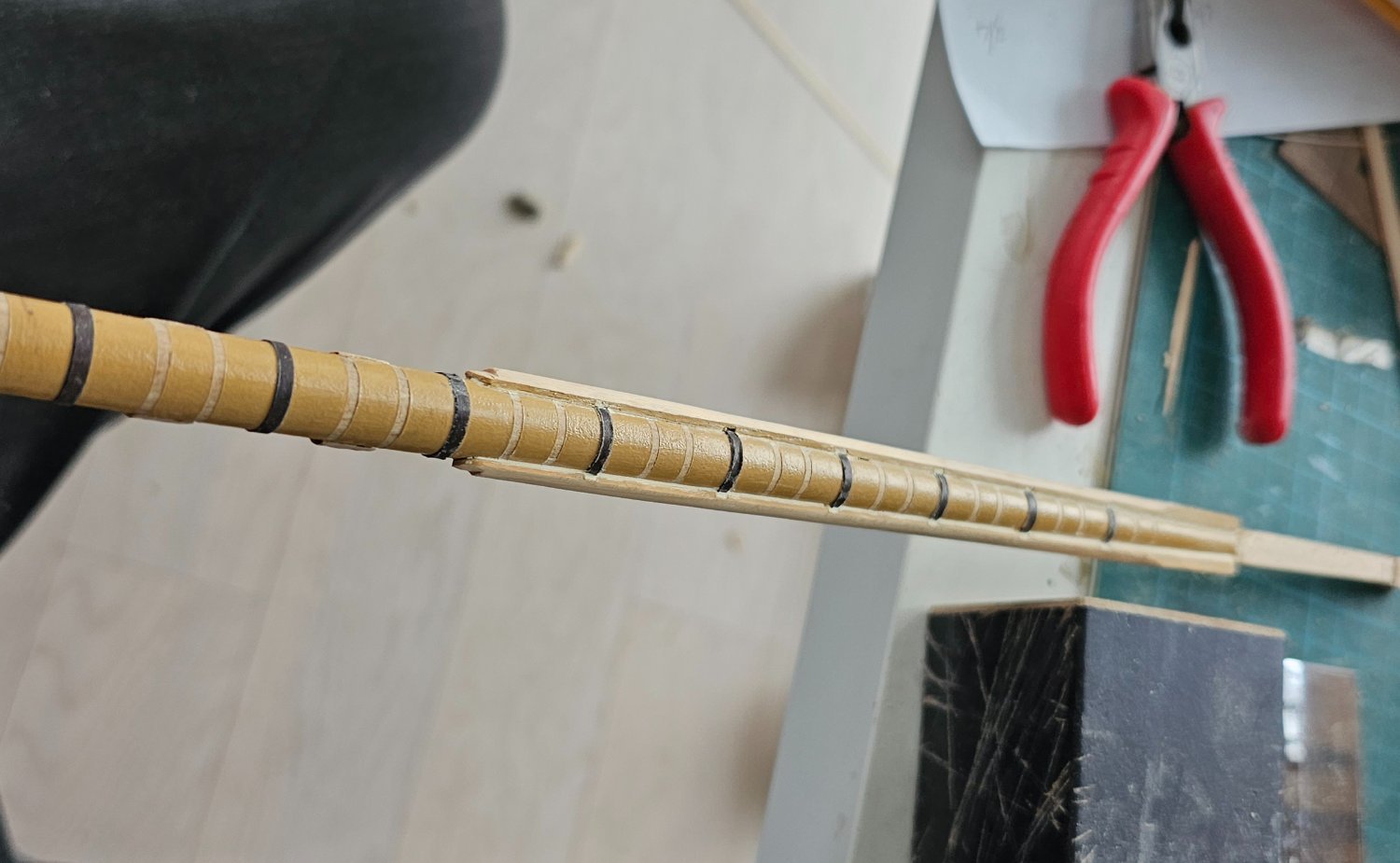
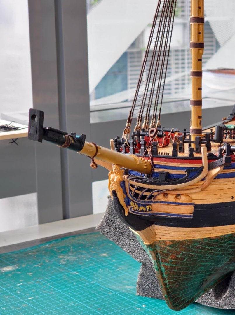
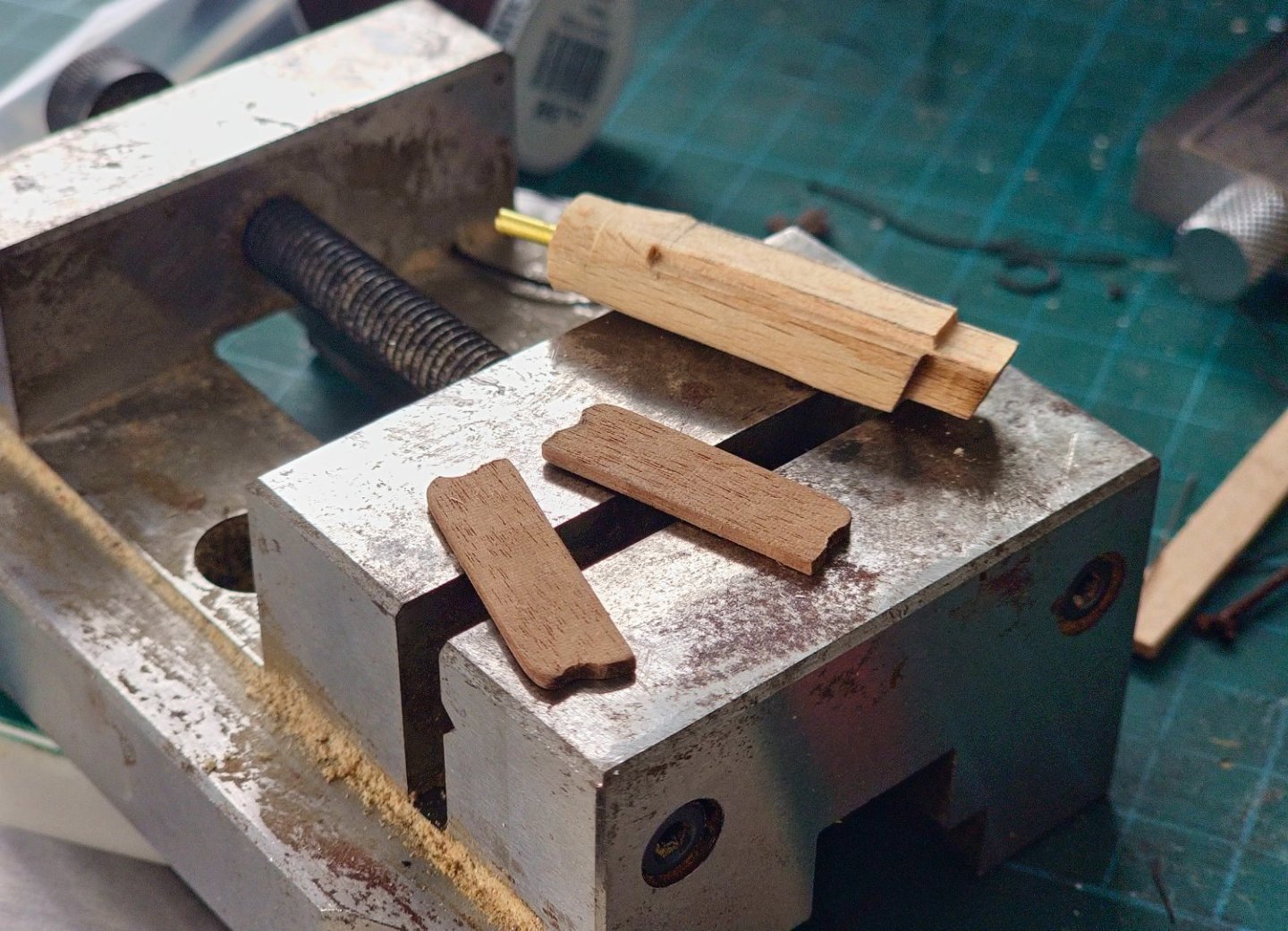
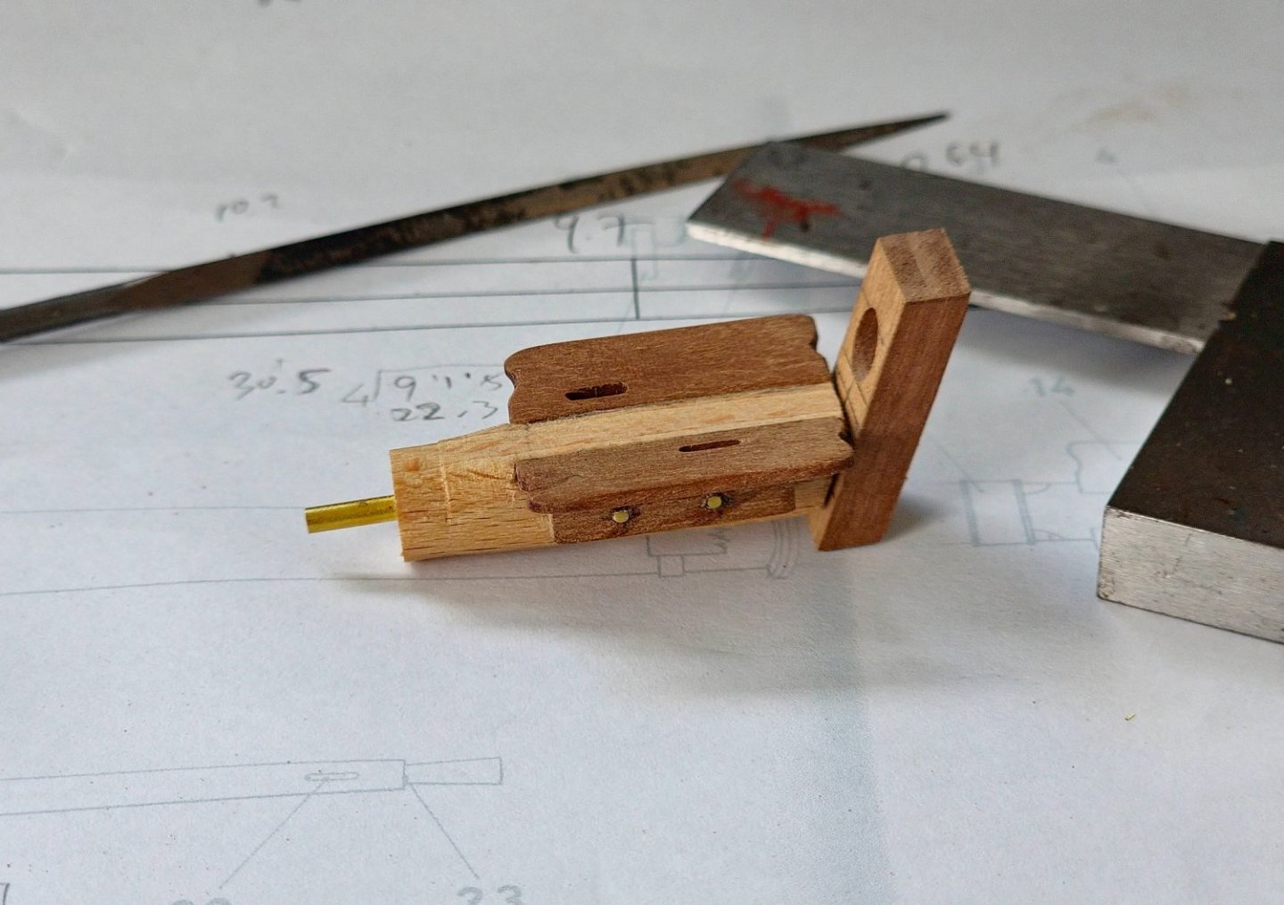
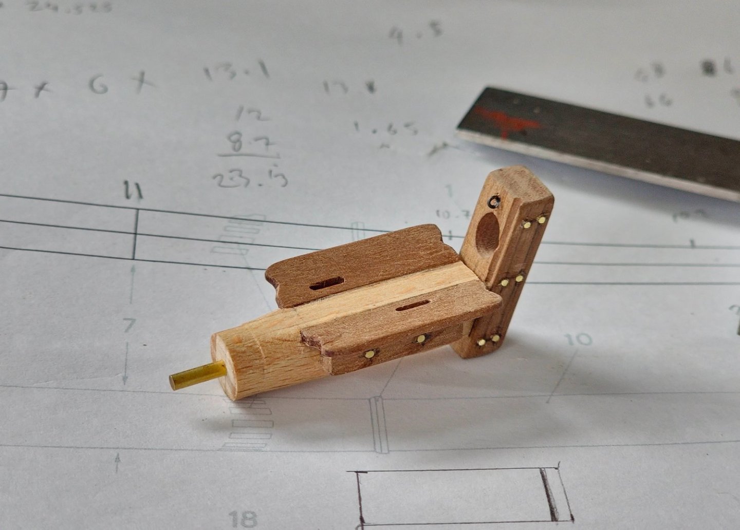
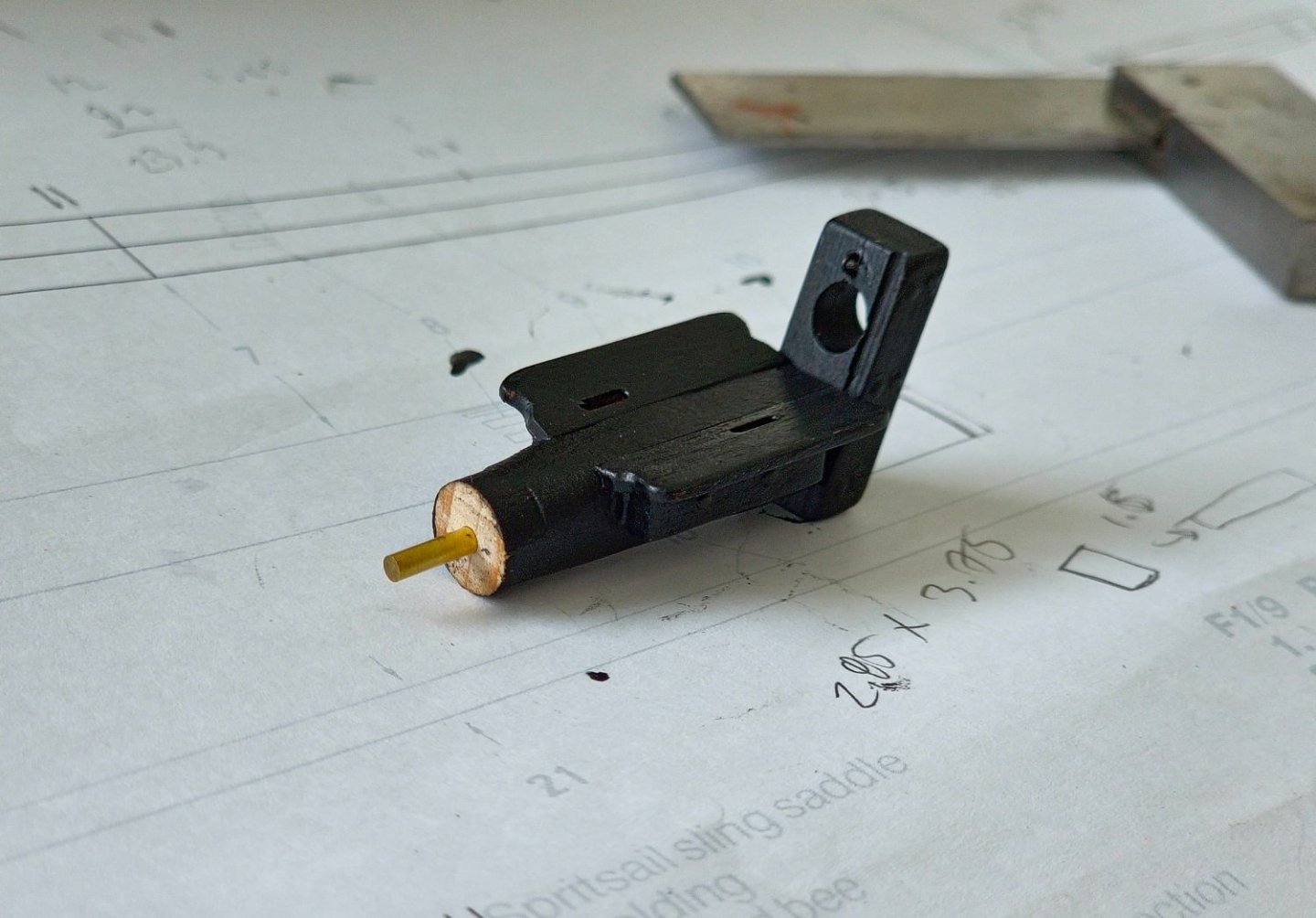
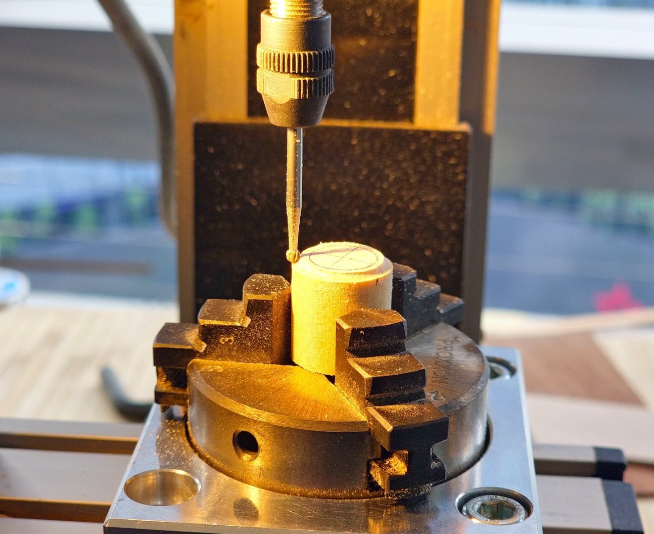
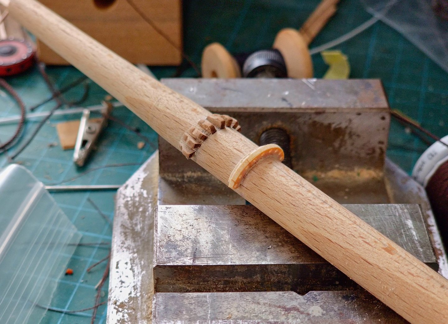
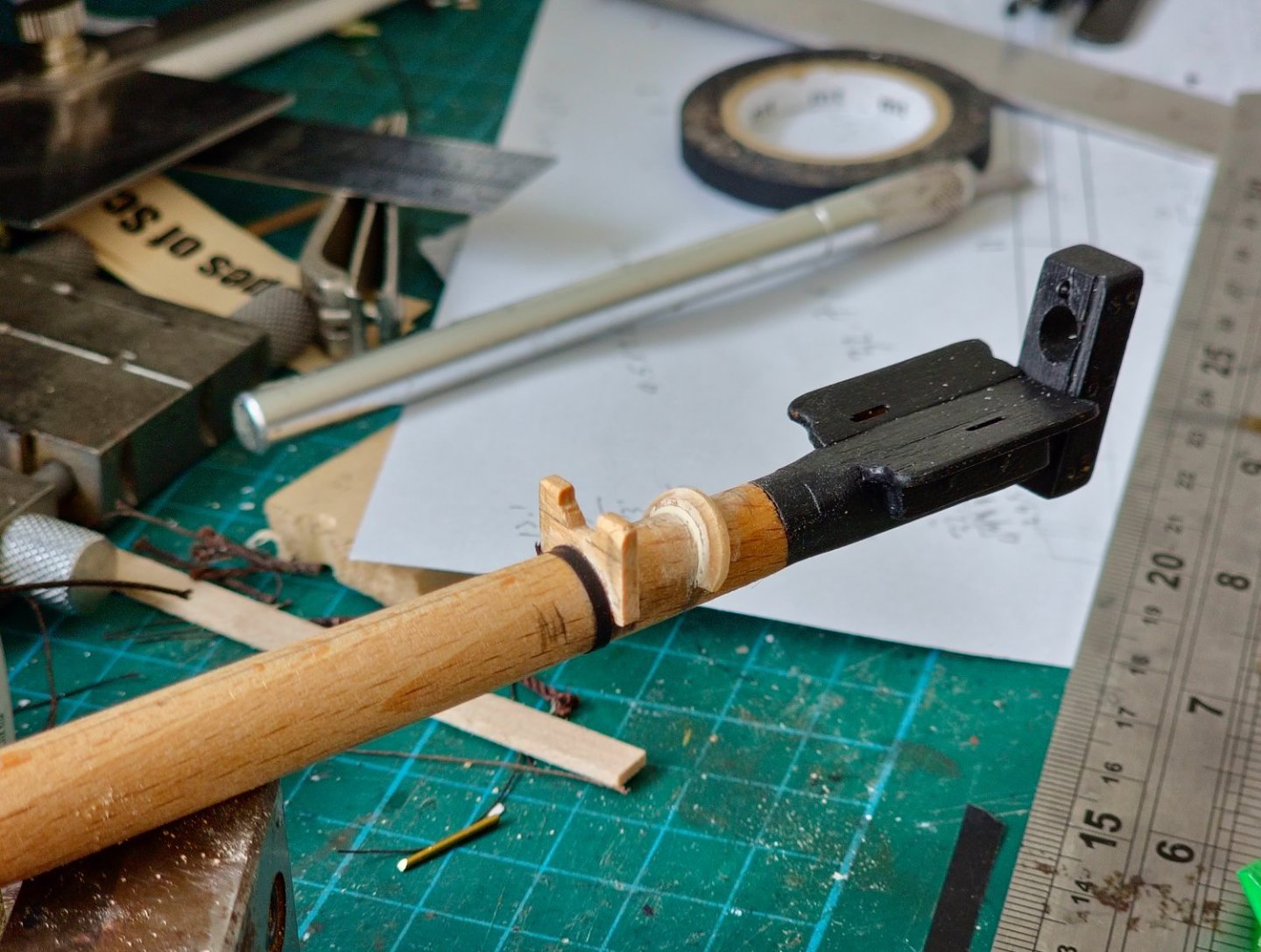
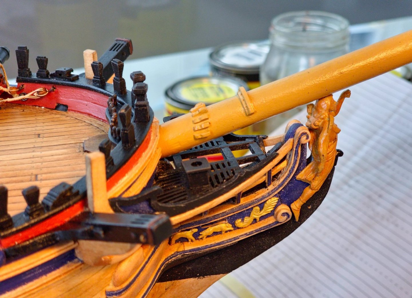
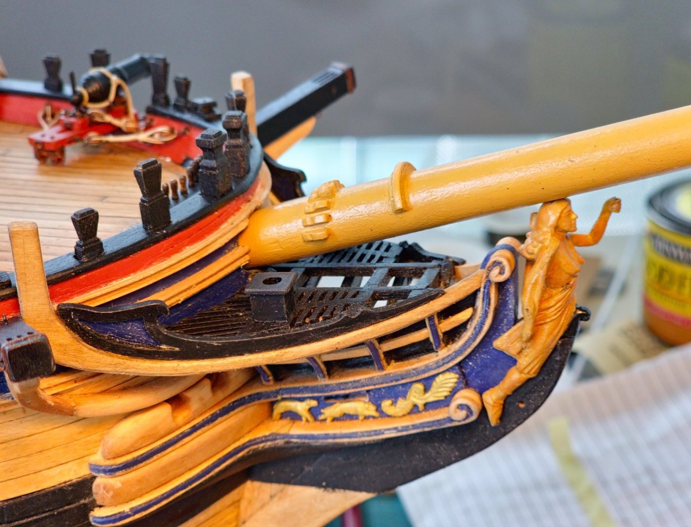
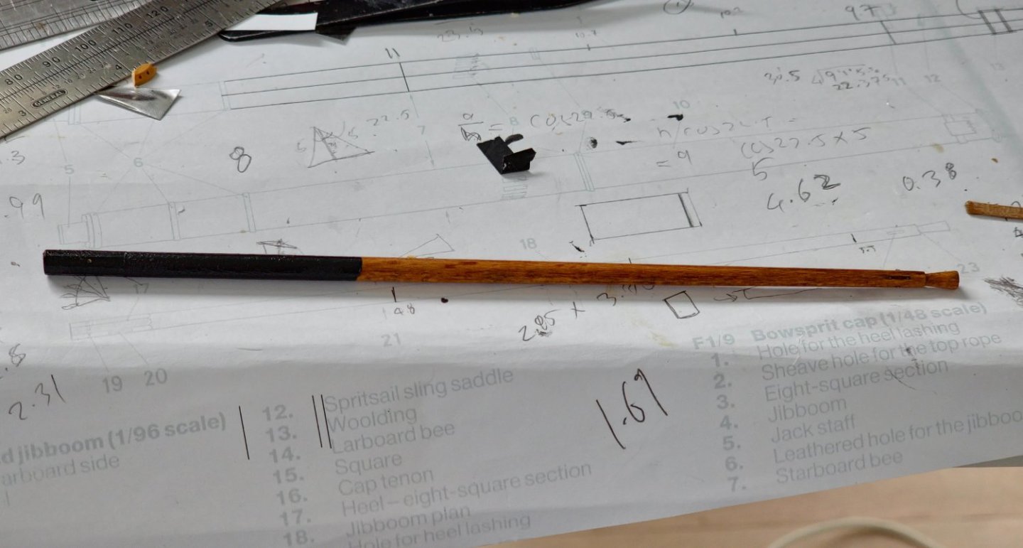
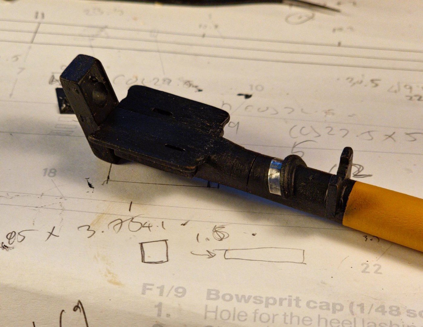
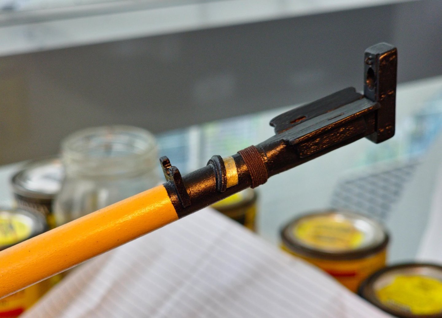
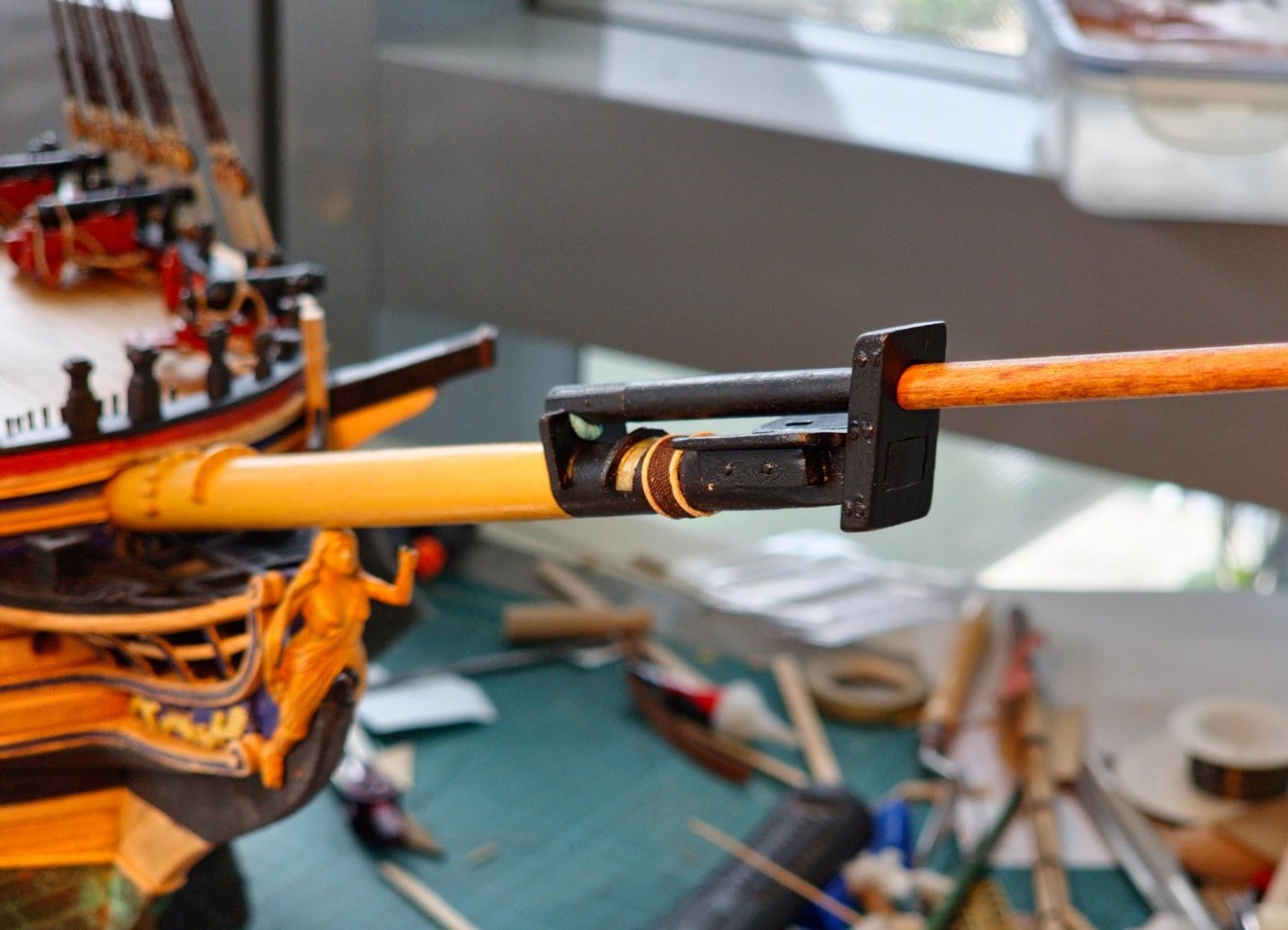
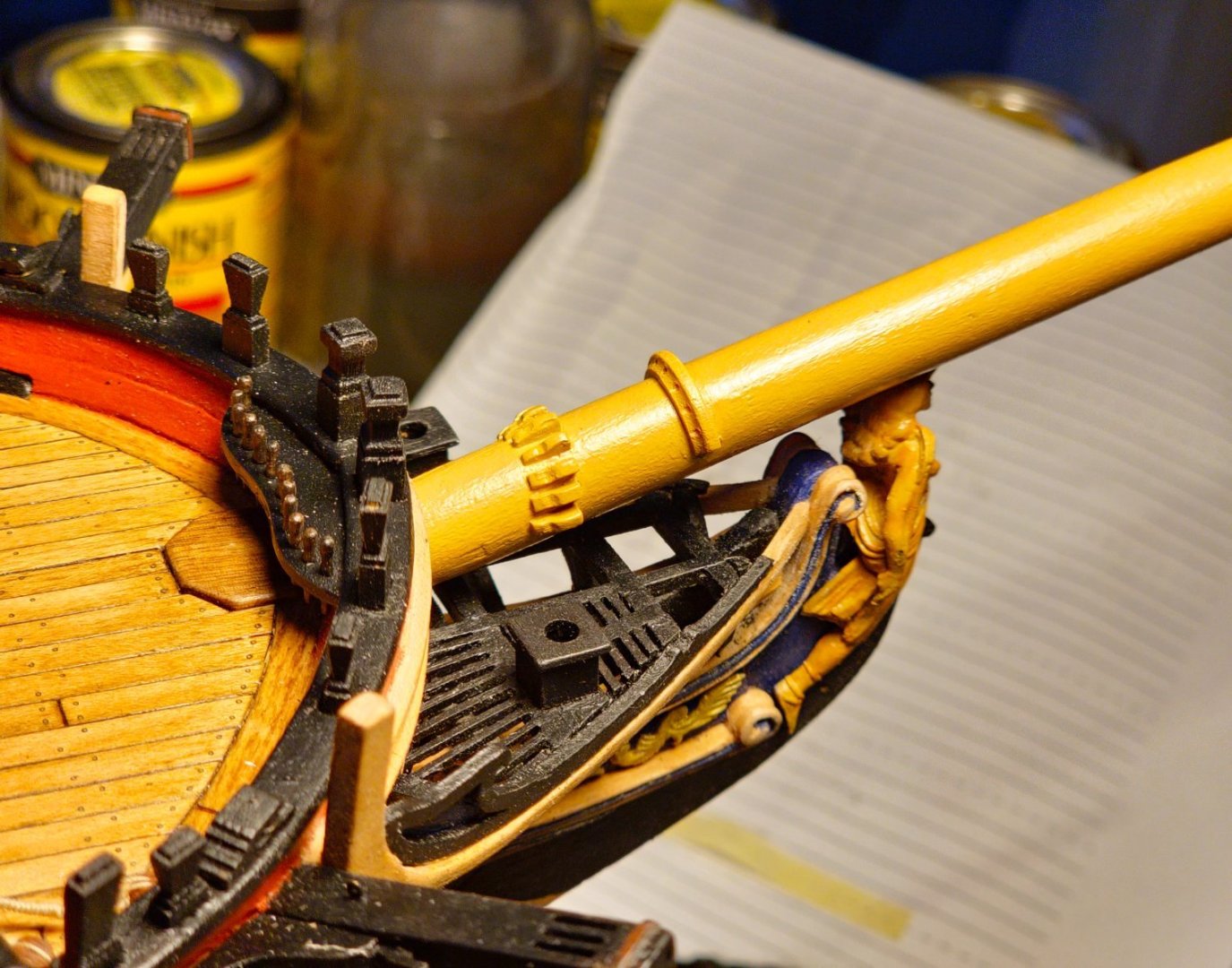
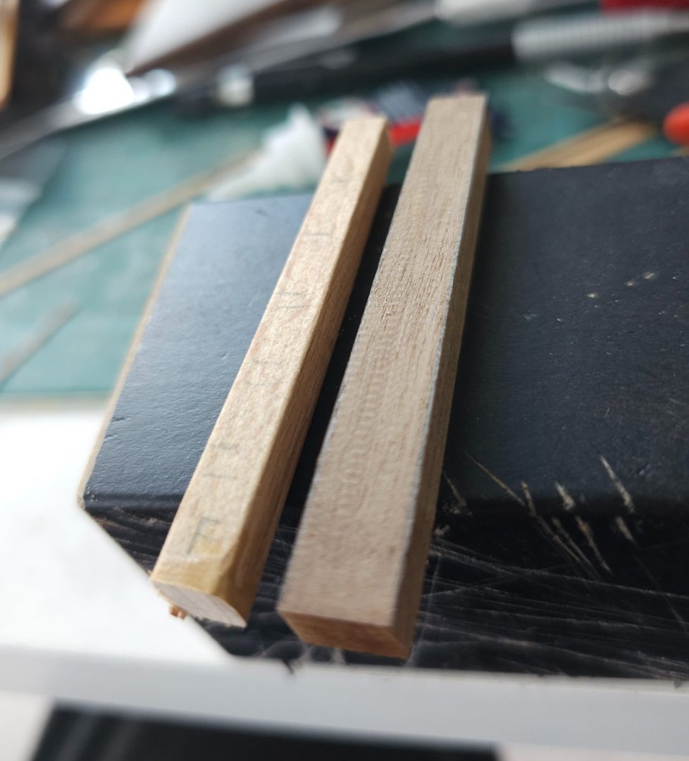
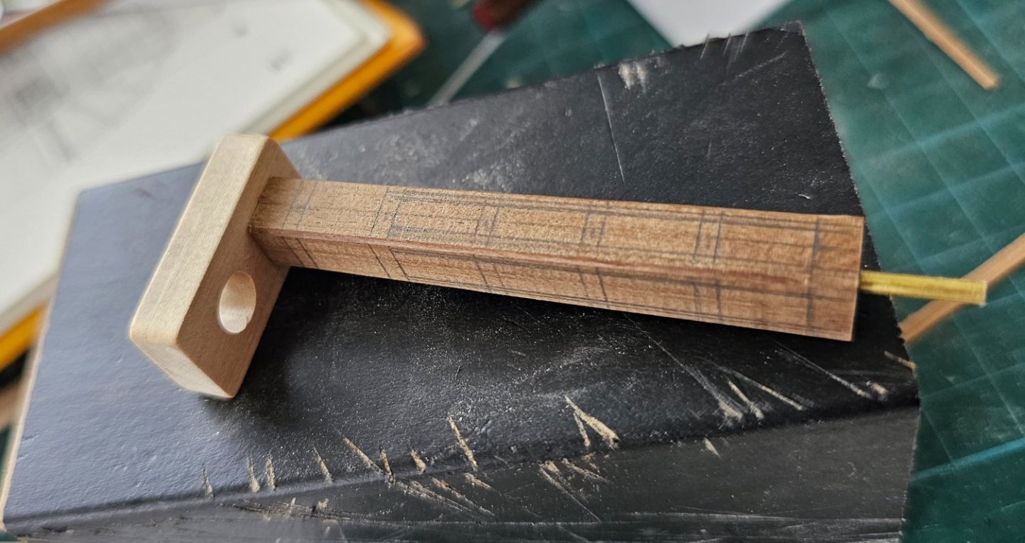
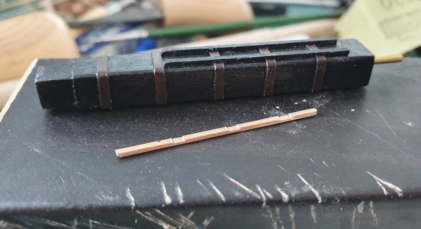
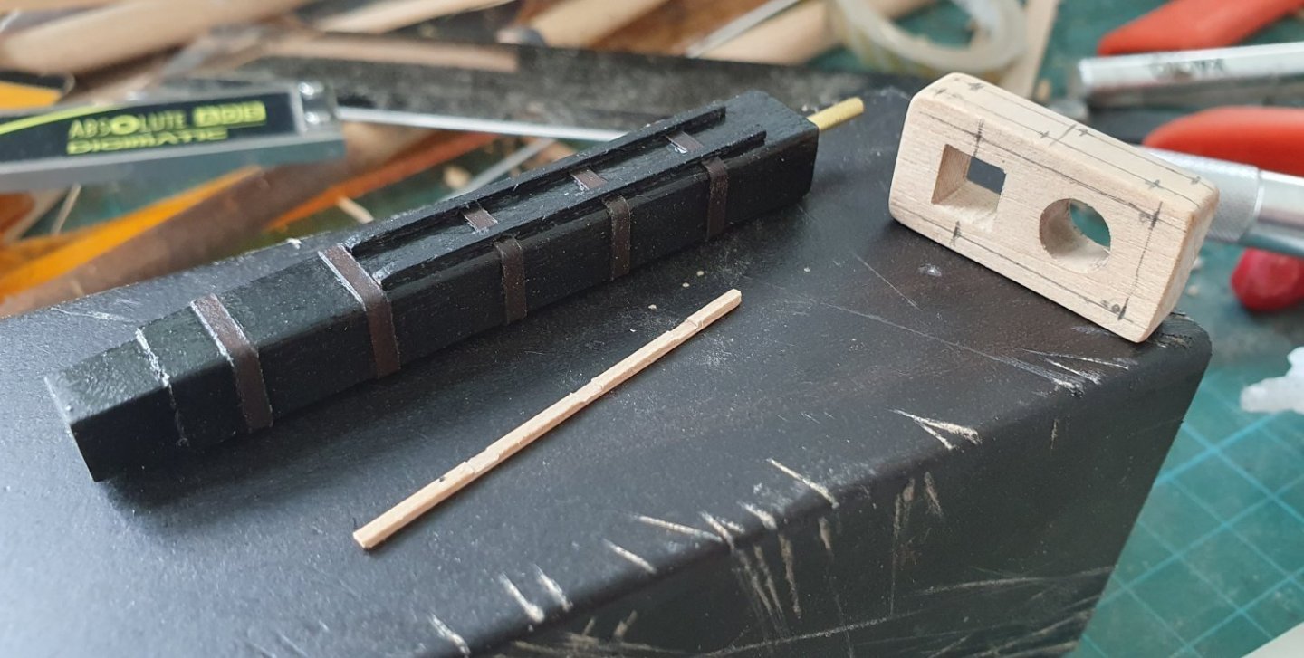
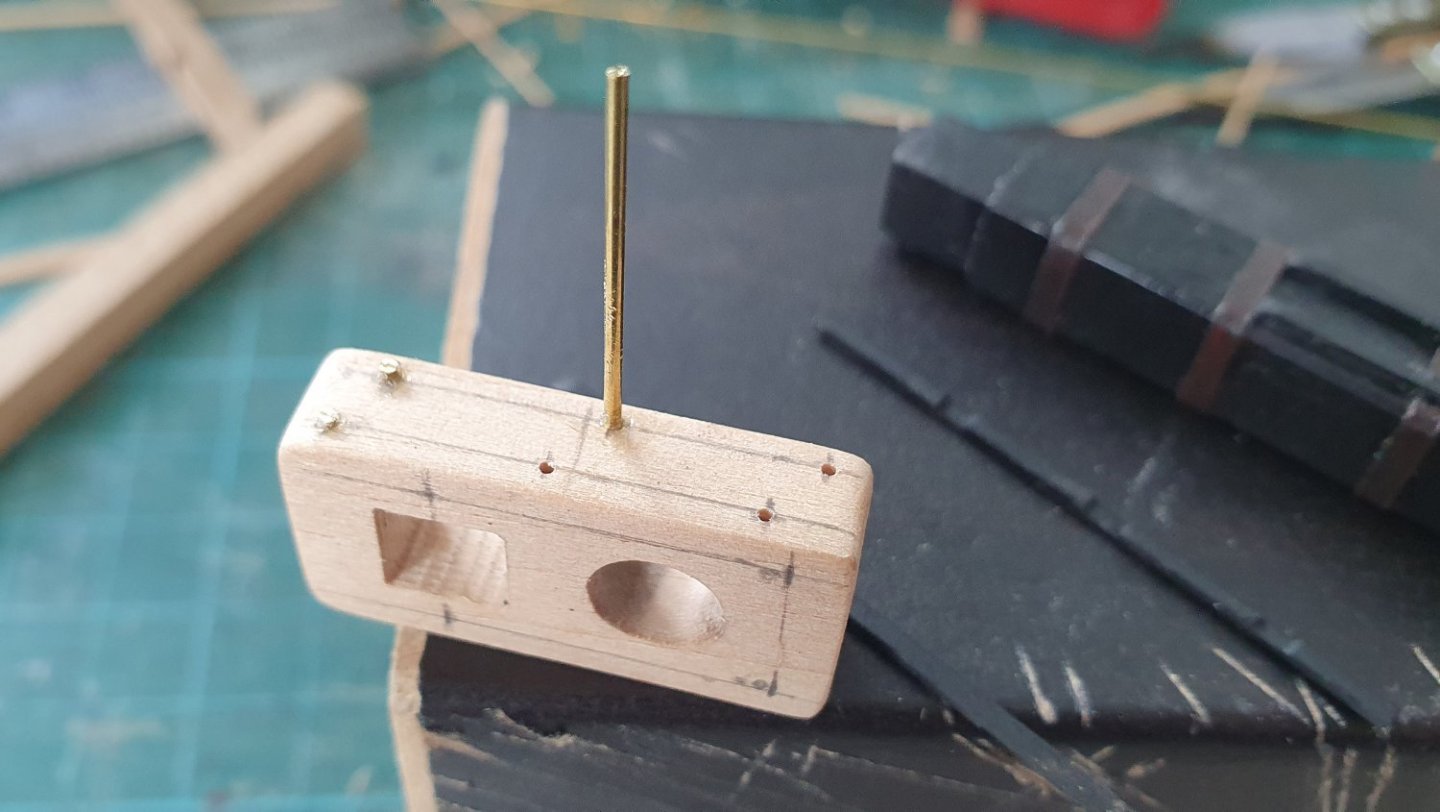
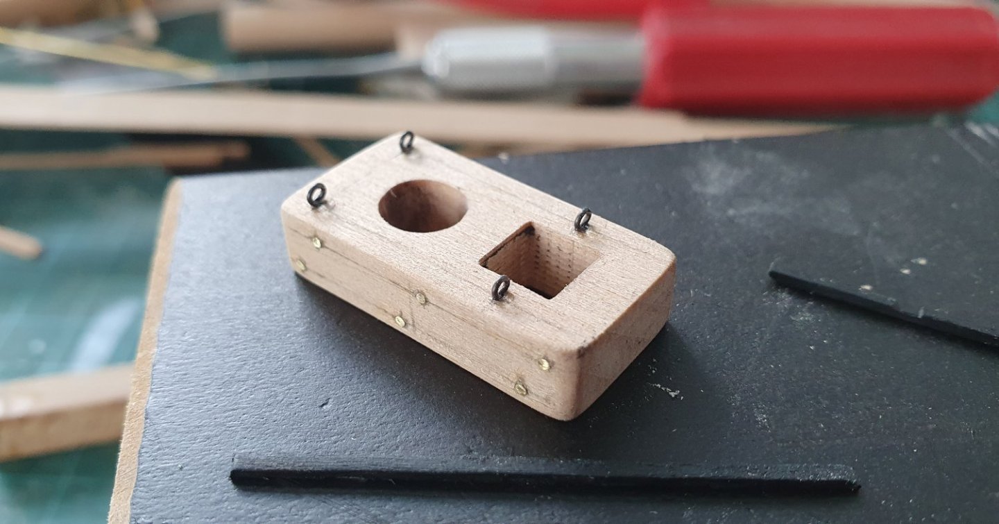
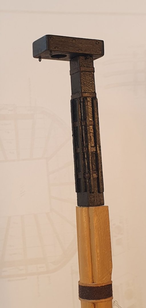
I decided to tackle the bowsprit. I had been avoiding it as I was unsure as to how I was going to be able to construct the geometry at the bees. I eventually followed the same method I used when building the masts and I constructed the bowsprit shaft and head as separate entities. This meant that I would not have to redo the entire assembly if I botched one of the many cuts that comprise the end section. I then dowelled the two sections together using some 2mm diameter brass rod and the join was covered up by the woolding. As suspected the end section was quite tricky transitioning from a tapered cylinder to a tapered square with an angled cap tenon further complicating matters. I milled out some slots for the bees. The bees and bee blocks were made from walnut. It will all be painted black so the wood does not need to match. I noticed from several sources that the sheaves in the bee blocks are one each side and staggered however the AOTSD drawings show two sheave holes per side. I went with the one either side staggered arrangement. A 1mm diameter brass rod was inserted to simulate the bolts through the sheaves. The end cap was cut out of some 5mm thick walnut. Getting the holes at the correct angle was quite challenging but I ended up eyeballing it. I drilled a groove down the starboard side of the cap to accept the jack staff and added some simulated bolts as shown in Steel. I should have used a smaller diameter wire for these as they are somewhat oversized. I spotted in Steel that there was an eyebolt midpoint at the top of the cap. I do not know what this is for but saw that HMS Trincomalee has the same arrangement. This does not seem to be in use in its parked-up configuration but I decided to include it anyway as it was no great bother. I scratch built all the saddles and cleats that appear on the bowsprit as I had followed the dimensions in the AOTSD which resulted in the kit items not fitting the larger diameter I ended up with plus the kit items were made from the dreaded walnut ply so were not that appealing. The saddles were all cut out of 15mm diameter dowel sections. I drilled a hole in the center corresponding to the diameter of the bowsprit at the saddle location. The height and profile were then formed using some shaped mill bits. They are quite delicate structures but should be OK once glued in place or so I thought until I realised that I had glued the fairlead saddle askew and then managed to crumble it to dust while trying to remove it. I formed the cleats from some 2 x 1.4mm walnut planks. I clamped eleven planks (9 + 2 spare) together in the vise and then milled them all at once for consistency. I then put the bowsprit into the dividing attachment and milled recesses corresponding to the cleat locations. This allowed me to get an even spacing of the cleats though it was quite a fiddly exercise. For the jibboom I started off with an 8mm diameter dowel. I needed the additional girth so that I could mill the octagonal section at the heel and form the stop at the other end. I had painted the bowsprit in the ochre colour with black at the overlap. I decided to keep the rest of the jibboom natural to mimic the mast configuration and I used the miniwax Puritan Pine stain to match the masts. I am now wondering if I should not have painted it in the ochre colour. I think I will wait and see if the natural colour grows on me. I added a strip of stainless steel sheet to simulate the lead sheathing that sits forward of the spritsail sling saddle according to Lees. It is a bit shiny so I will have a go at dulling it down using some paint. The woolding was made using 0.5mm diameter dark brown RoS rope which is the closest I have to the diameter indicated in Steel. I used cherry shims to form the protective hoops as per the main mast. I still must decide if I am going to paint these black or leave them natural. I decided to stop the process here and remove the jibboom as I will be working on the rigging which means that I will be spinning the ship around from port to starboard and the delicate jibboom assembly will not survive a hard clonk against the desk lamp. I may install the bowsprit though as this will allow me to further progress the rigging and add the fore stay and preventer stay.


-
Thanks Dave. I have just started the rigging but I can see that it is going to be a lot more challenging than I initially thought. It looks like you have made some good progress on your Diana. You will be rigging in no time. Regards, David
-
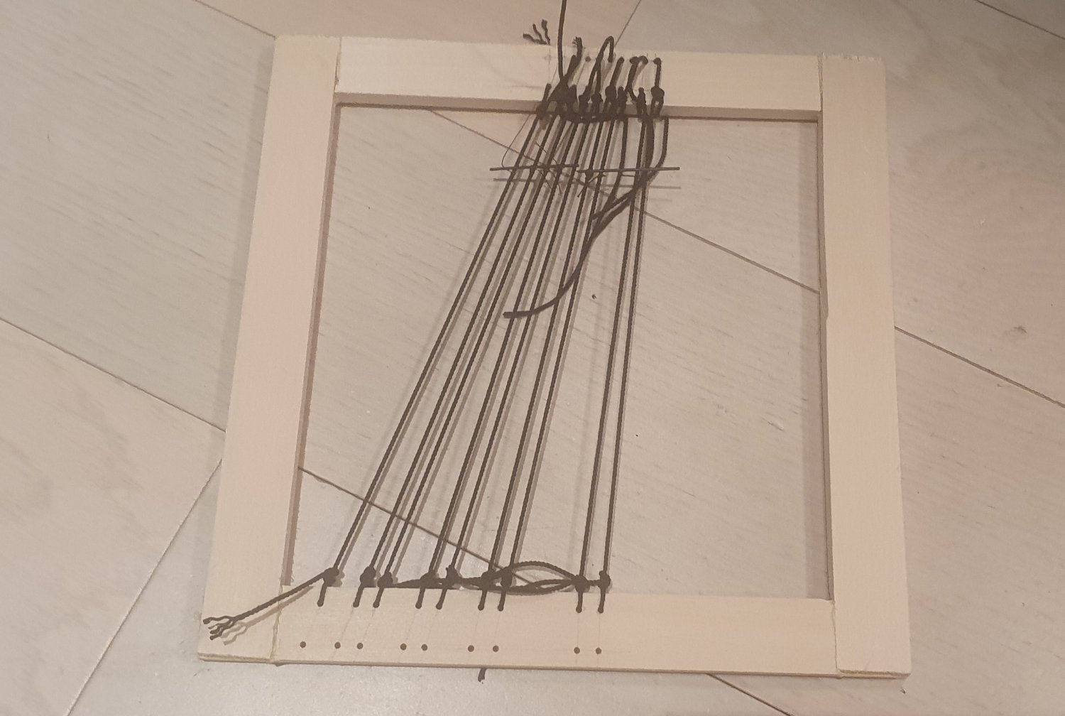
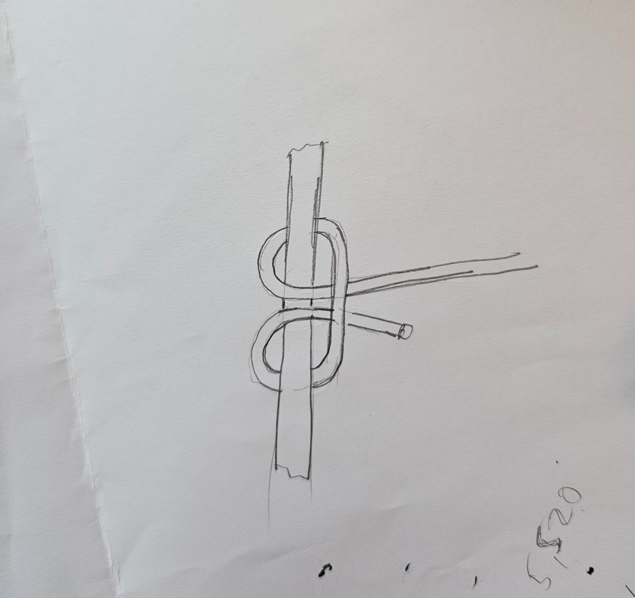
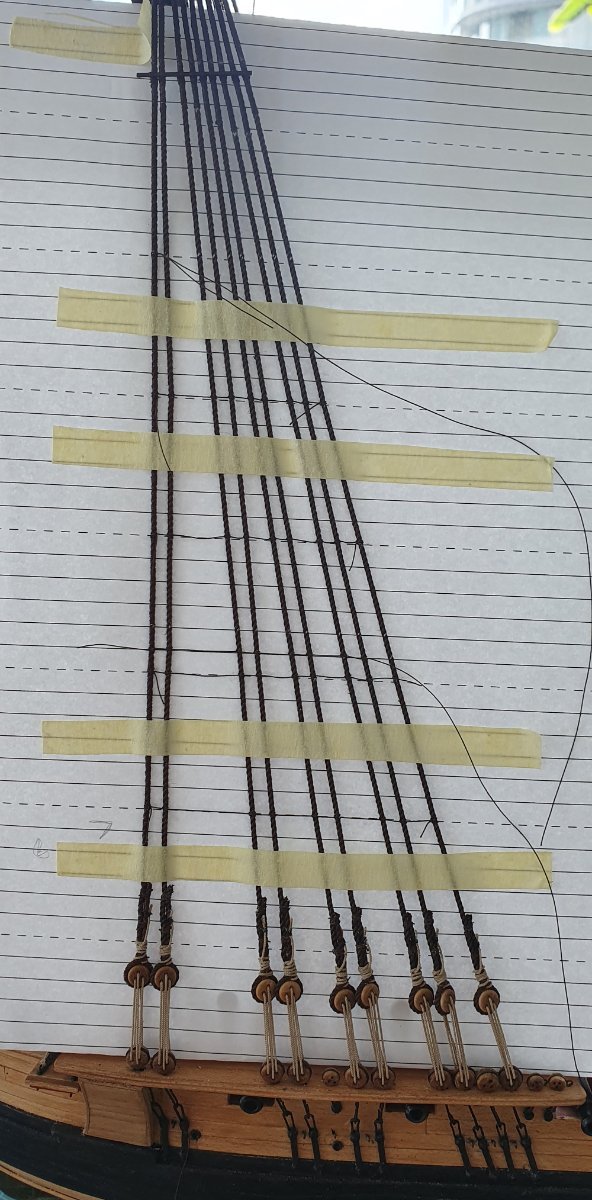
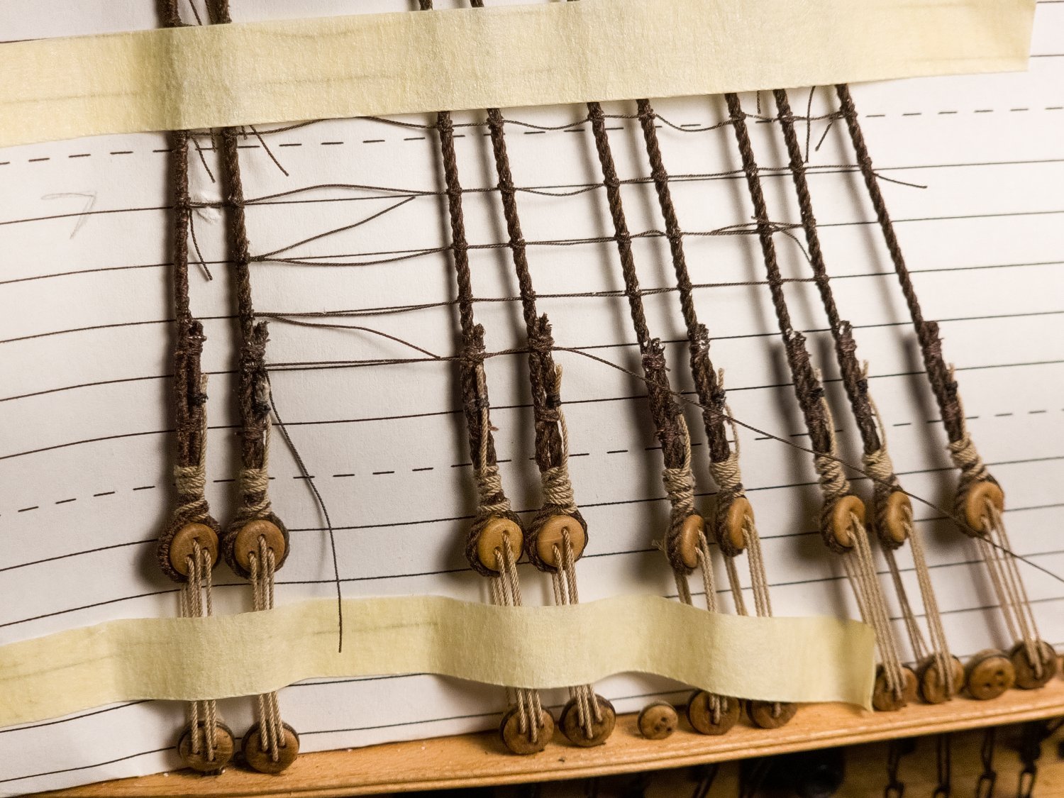
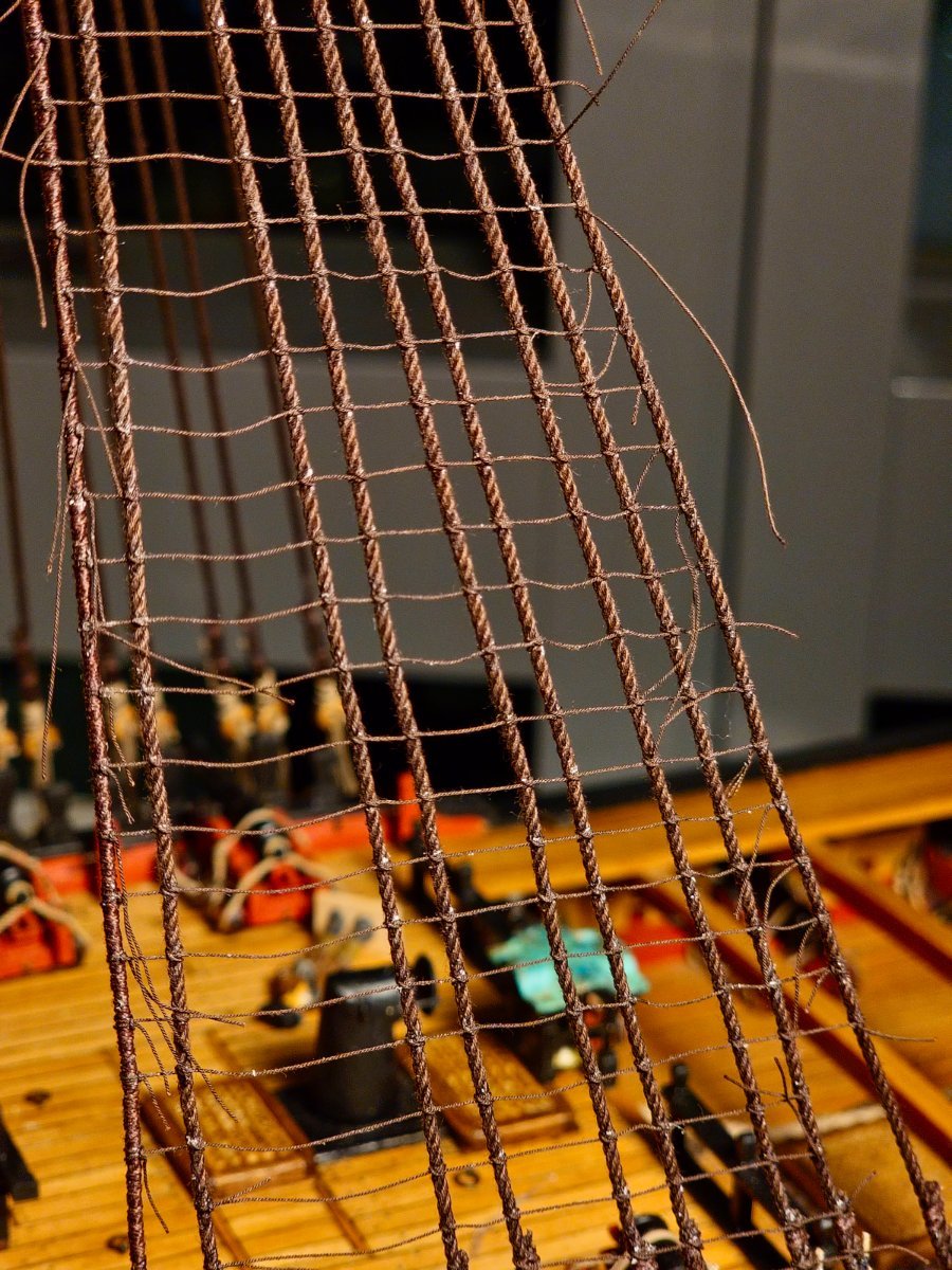
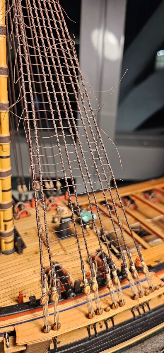
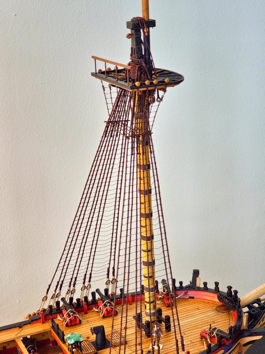
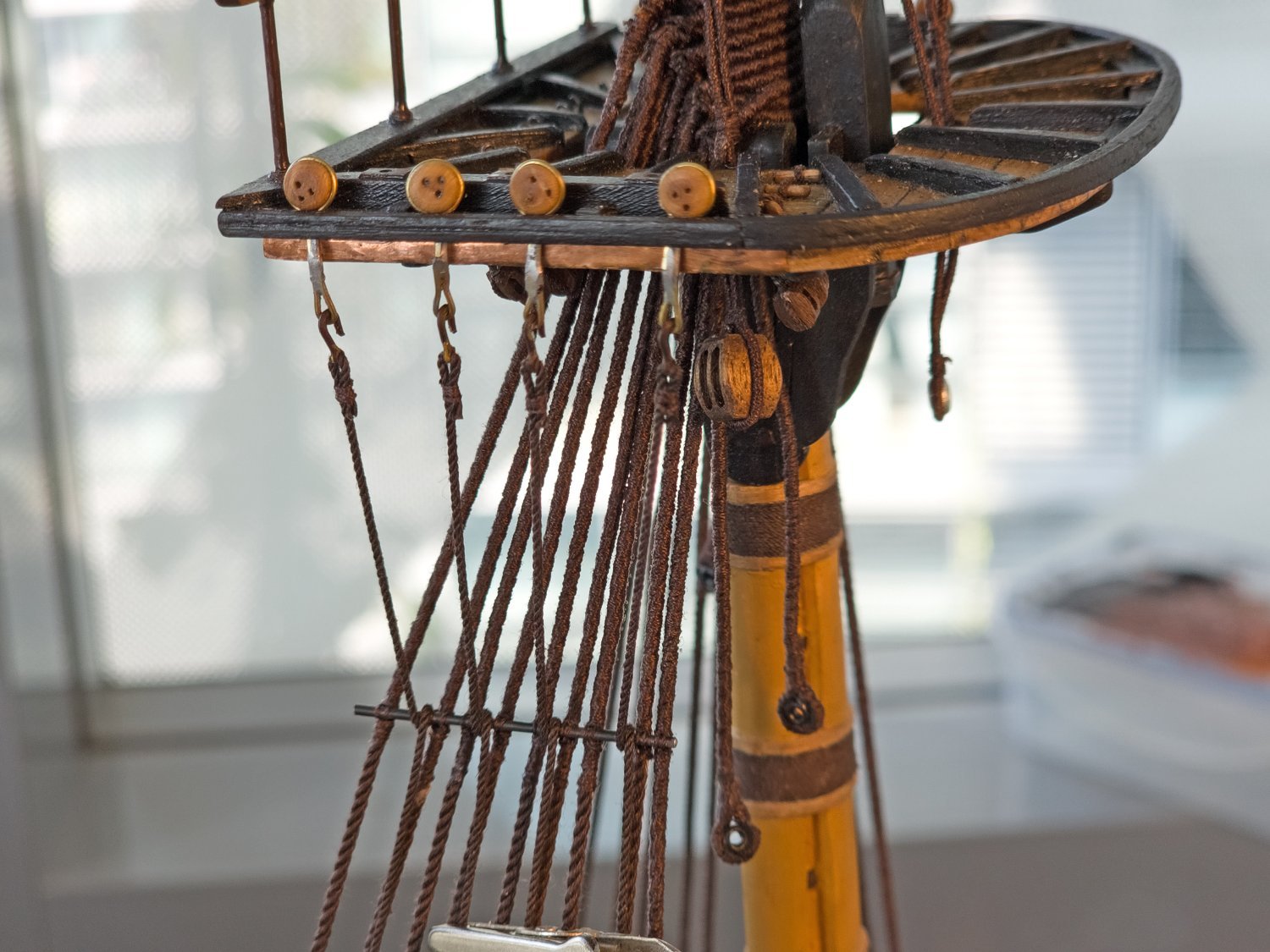
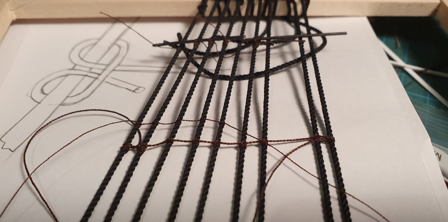
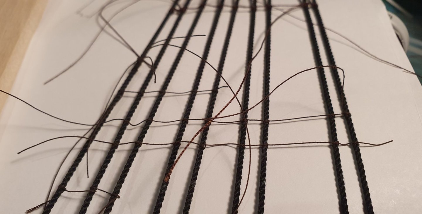
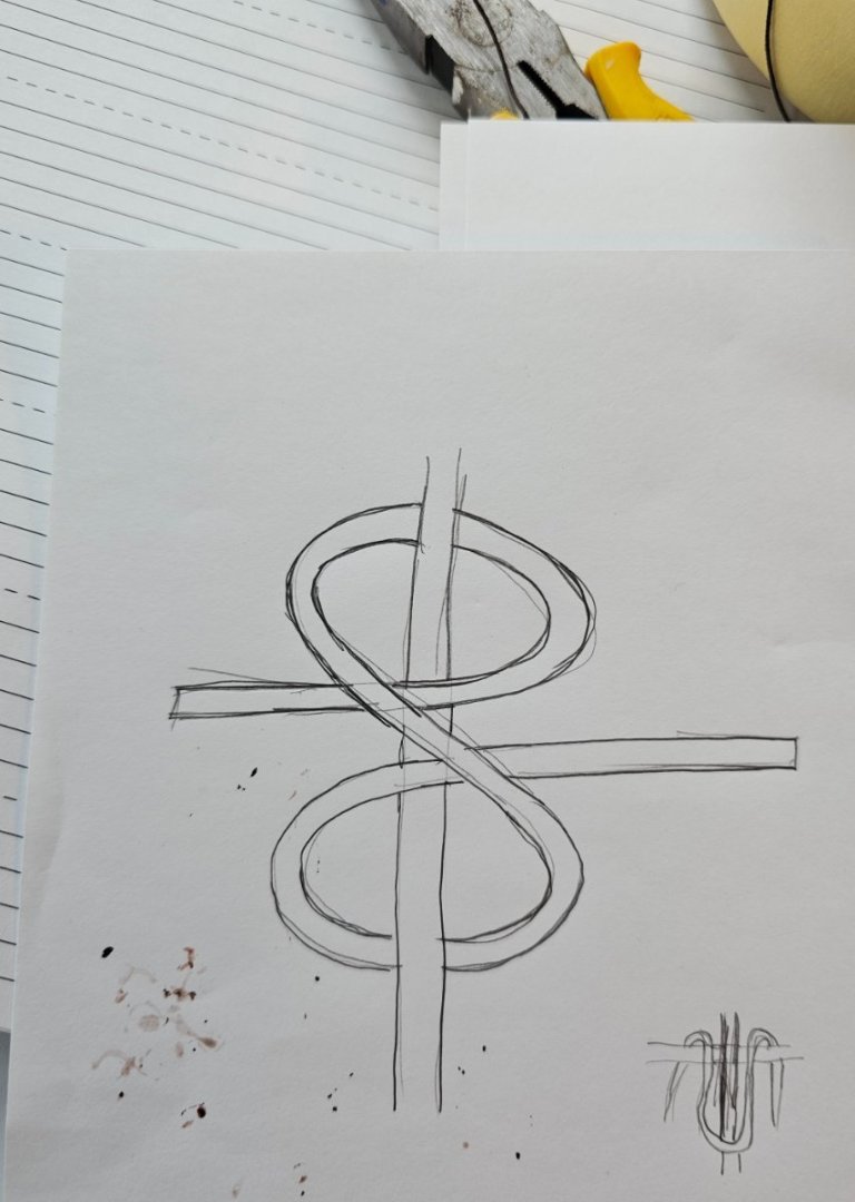
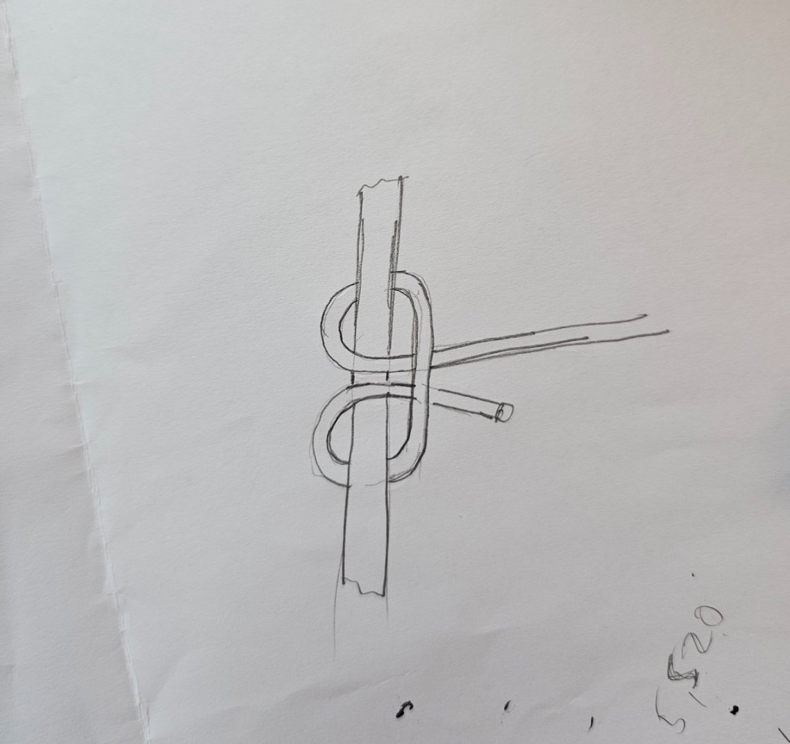
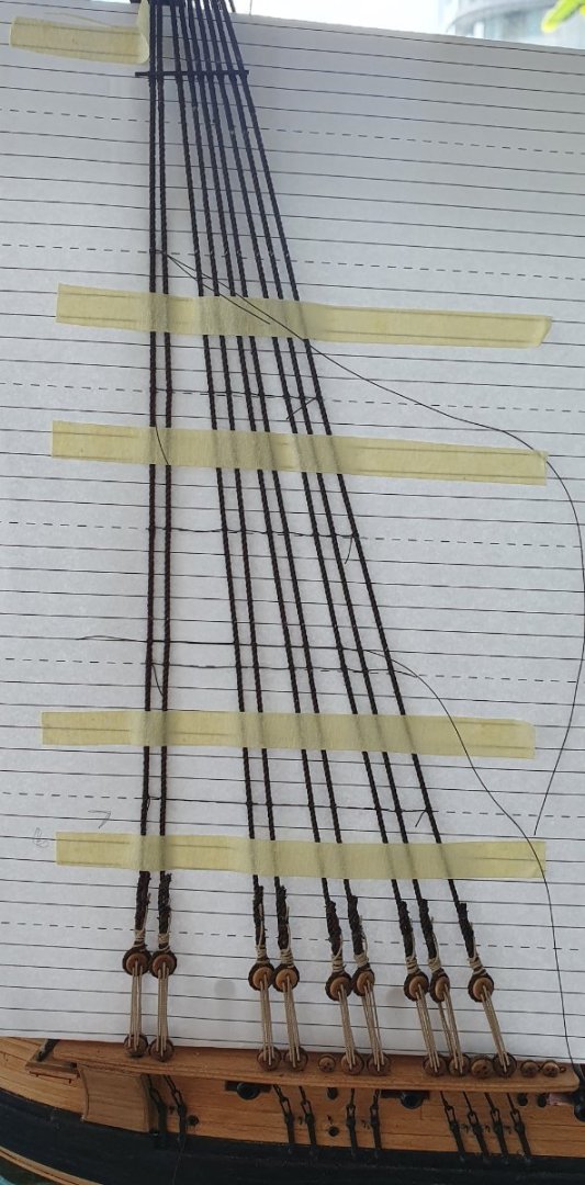
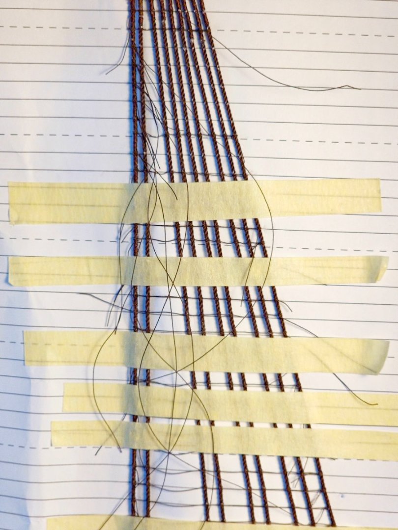
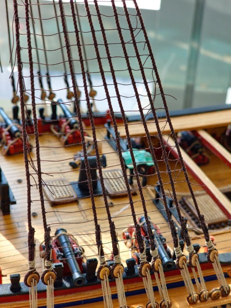
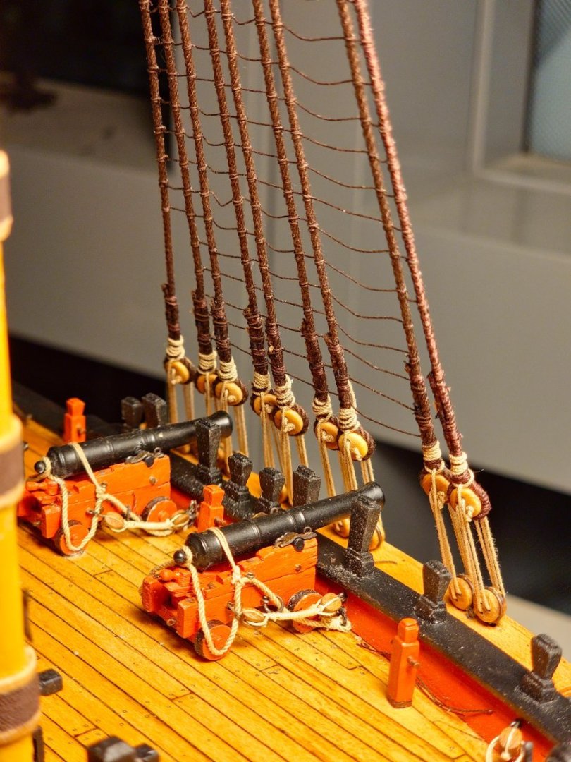
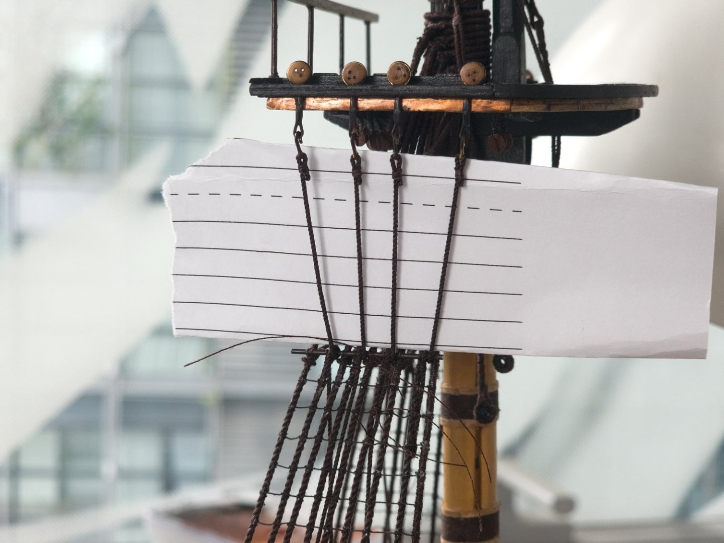
Time to start phase one of the dreaded ratline tying stage. I decided to give myself a leg up and have a bit of a practice before leaping onto the model. I knocked up a quick frame out of some scrap wood and then approximated the run of the shrouds. I had read in Steel that the ratlines should be 0.19mm in diameter. I did not have that size in my stock of dark brown thread but noticed that Dunnock had used 0.25mm diameter in his Diana build to good effect. I experimented with some 0.25mm diameter Gutterman polyester thread, some slightly thicker Gutterman thread and the 0.25mm dark brown from Ropes of Scale. Unfortunately for my bank balance the 0.25mm RoS was the most pleasing to my eye. I initially thought that I could use a seized eye at either end but I was unable to get seizing small enough so I resorted to the tried and tested cow hitch at either end and clove hitches in the middle. I could not help doing a triumphant moo every time I completed a well tied cow hitch though this soon turned into a mournful lowing as I realised that they are very fragile and tend to unravel once the excess thread is trimmed close to the knot. Once this happens it is not recoverable as there is not enough material left to retie the knot which means the whole row must be replaced. I only discovered this after I finished installing all the lower fore mast ratlines so I will have to look for an alternative knot for the remaining masts. Lees gives a distance between ratlines of 13-15 inches so I split the difference and settled on 14 which comes out at about 5.5mm at 1:64 scale. I drew up a series of suitably spaced lines on the CAD and printed this out to act as a template. Conventional wisdom suggests that one should first tie every 5th row to prevent the awkward hourglass shape to the shrouds so this is how I progressed but it was not enough to prevent distortion. I was in two minds whether to continue the ratlines above the futtock stave as the shrouds are very close together in this area but looking at the condition on HMS Victory and HMS Trincomalee it would appear that they did carry on up past the futtock stave. Drat. After what seemed like months of work, I completed the lower foremast ratlines. The result is not great and there are some real wonky ones but the dark colour and thinness of the rope means they tend to fade into the background a bit when you are not focusing on them so they will have to do. The whole ratline tying exercise is a real mixture of tedium and frustration. It is very challenging to get the rope to sit in the right place, to hang in a pleasing manner and to stop it distorting the run of the shrouds. It will probably take me to the last shroud on the mizzen top mast before I have any semblance of technique. Unfortunately, while the RoS rope looks the best it also has the annoying propensity of not wanting to stay knotted so I gave each knot a splosh of diluted white glue to help encourage the correct behaviour but sadly this did not help with the cow hitch conundrum. I added the catharpins. There seems to be many methods of constructing these as well as the methods of attachment to the shrouds. While I liked the look of the served variety, I decided to go with a plain 0.8mm diameter rope seized directly to the shroud. There is a lot going on in this area so I decided a less is more approach would be appropriate to reduce the clutter. I initially fixed these above the futtock stave but then cut them out and installed them below to prevent them creeping up once they were tensioned. I tied them fairly loose thinking that they would tighten up once the futtock shrouds were tensioned. They did but are still a touch loose. I am hoping that the top mast shroud installation will provide the final bit of tensioning. I installed the futtock shrouds. These were 0.8mm diameter rope. They had a PE hook seized into the one end and were then wrapped once around the futtock stave and then lashed to the adjacent shroud with three seizings as detailed in Lees. These were then finished off with a few ratlines. Once in place I felt that the proportions were a touch off and I could have done with moving the futtock stave slightly further down the shrouds however I am not going to dismantle everything to see if this is a worthwhile improvement. They will ultimately be partially obscured by the yards and other rigging so any minor adjustments would be a waste of time.


-
Thanks David. I have been enviously studying your ratline post. I was puzzling about the size of rope to use. Steel notes these should be 0.19mm in diameter but I do not have any dark brown rope at this size. I saw that you have used a 0.25mm diameter rope and the result looks very good. I think that is the route I will go down as well. Regards, David
-
Thanks Dave It is certainly worth you while to swap out the kit supplied strops with these. I would have ideally liked to get the pre-blackened versions from HiS Models but they were out of stock and I could not be bothered waiting. You still have plenty of time to get an order in though. Regards, David
-
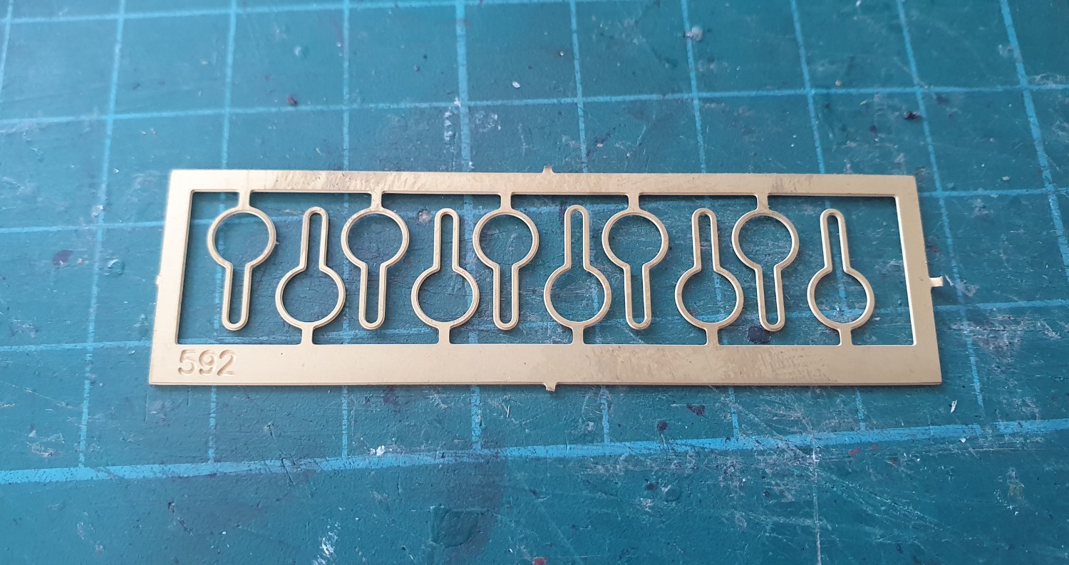
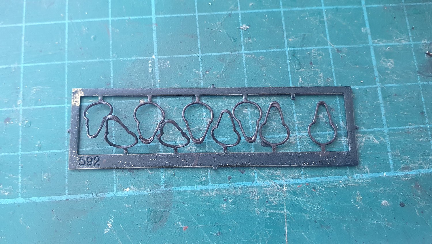
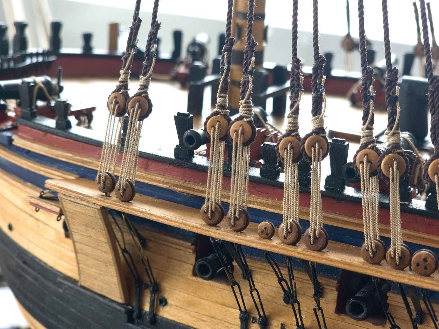
My strops arrived from Amati. The delivery was quite swift. I opened them up to accept the deadeyes before giving them a coat of rattle can matt black. I figured that I would do less damage to the paintwork if I just had to close them rather than open and close them once painted. I added a splash of weathering powder and then give them a spray of poly to give the coating a fighting chance of staying on but it is a slim chance. I employed the same jig as before and attempted a version of the complicated twisted lashing around the deadeye as detailed in Lees. It is a real exercise in frustration to do and the result is quite clumsy. Still once all the ratlines and lanyards are in place, they should not be that visible. I gave the lanyards an experimental yank and this time everything stayed in place. Happy days although tempered by the knowledge that there are many more still to go. In an attempt to get the served lengths of the shrouds to line up I clamped a length of wood to the mast although this was only marginally successful as the served length ended up getting longer as I worked through the shrouds and have a distinct downward slant rather than the neat horizontal I was aiming for. Not the end of the world as it is barely visible. After plodding away for a while, and taking many sanity breaks, I completed the lower foremast shrouds. The spacing between the shrouds is not the best. They are too widely spaced in some areas and are too narrow in others such that they interfere with the cannons. In an ideal world these should be relocated but it would be too catastrophic to try that now so I am just going to live with it. As I progressed the stack of shrouds at the tops continued to grow to an alarming height. This seems to be higher than others I have seen. Perhaps I did not tamp them down firmly enough when installing them. To break up the shroud installation I had a go at completing the strops for the futtock shrouds. For these I resorted to plain 0.5mm diameter brass rod. It is slightly thicker than the annealed black wire I was using previously. The result is not as good looking but I can get a much stronger solder joint using the plain brass variety. I hope they will be passable once they have a coat of paint. I tightened up all the lanyards and attempted the convoluted lashing pattern as shown in Lees but with an additional hitch at the top to prevent them unravelling. They are a bit of a mess but that is what comes with learning in the job. I installed the futtock stave at the top using a 1.0 mm diameter black annealed wire pulled straight I normally use the two-plier method but for the larger diameter I had to resort to wrapping it in the vise and then pulling upwards while standing on it. These were lashed in place using some dark brown Gutterman thread. I mocked up the futtock shrouds and these distort the lower shrouds quite dramatically. I will have to install the catharpins first before I rig these. I guess I should have a go at some ratlines now rather than wait until all the lower masts are finished. That way I will break up the tedium of doing them all in one go.


-
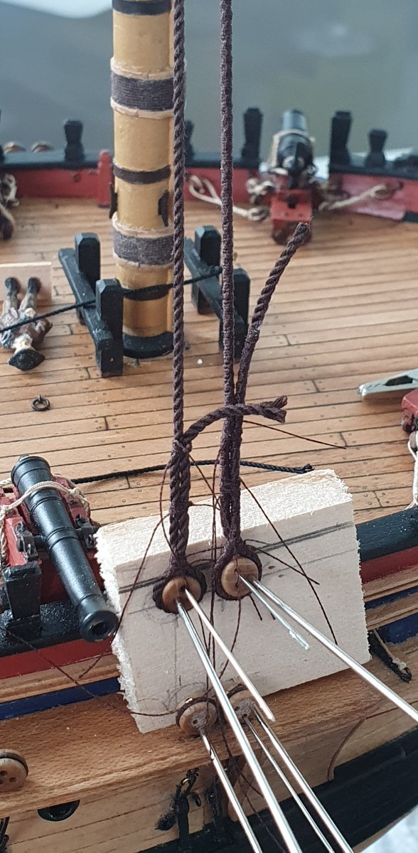
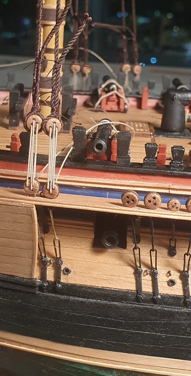
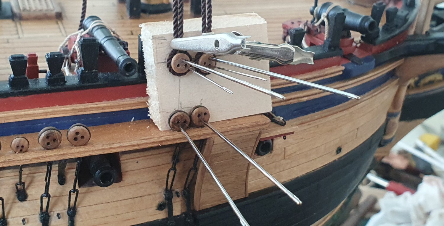
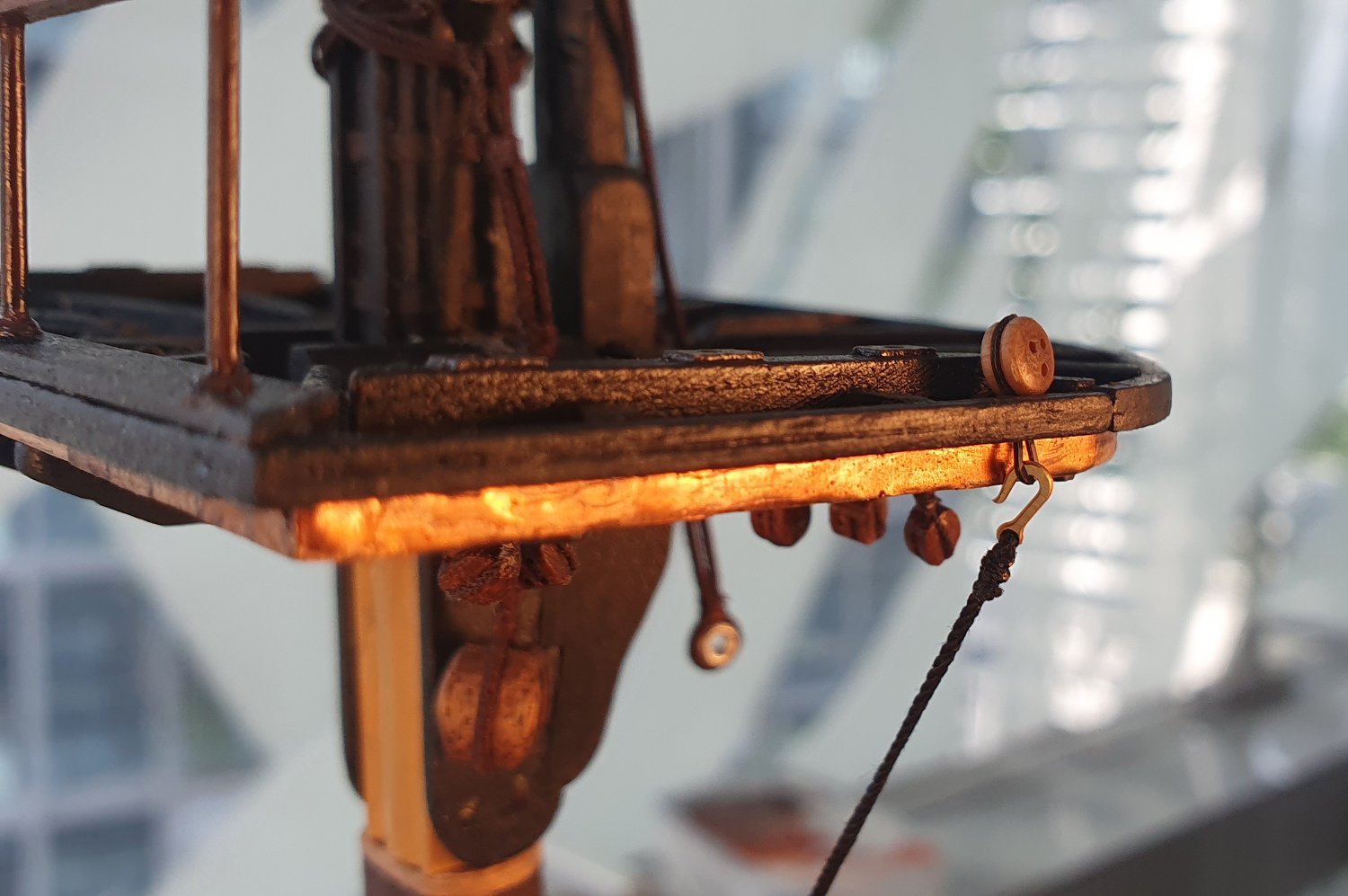
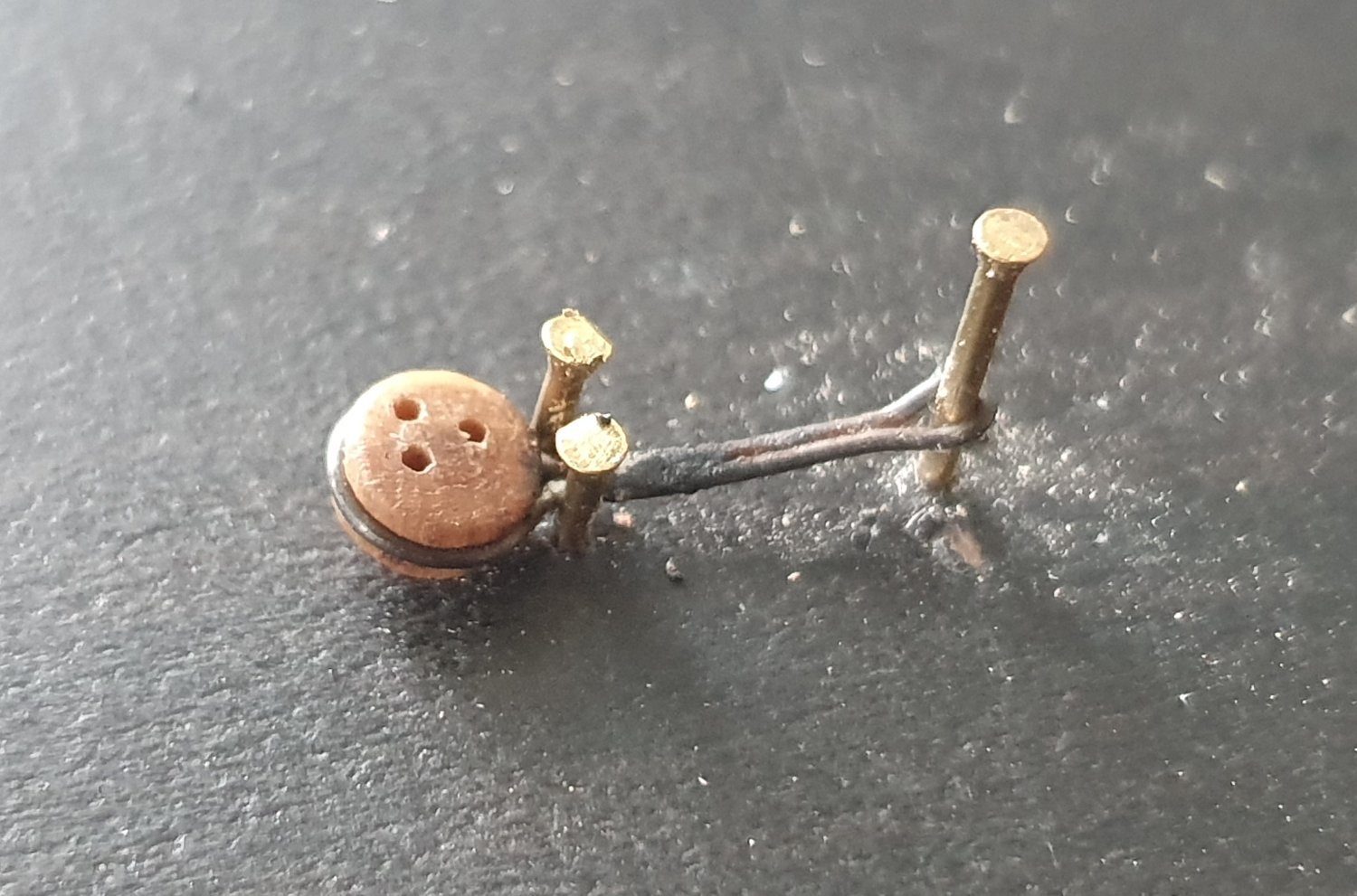
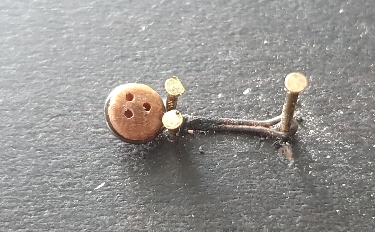
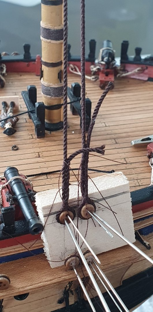
I started to install the initial bit of standing rigging and encountered the first series of major mishaps. I began by working on the fore pair of starboard shrouds for the foremast. I had a lot of trouble using the bent wire approach to get the correct deadeye spacing as the wire kept popping out of the deadeye holes. I eventually cut a piece of scrap bass wood with a chamfered edge to match the slope of the shrouds. The deadeyes were then held in place with multiple needles. This was also not that that secure but slightly better than the bent wire option and hopefully have me a better chance of getting the upper deadeyes aligned horizontally. For the fore mast lower shrouds, I used a length of 1.2mm diameter dark brown RoS rope. This was the closest I had to the 1.13mm diameter as indicated in Steel. I tackled these in pairs starboard to port fore to aft. Once the lengths of the shrouds were determined I served the forward shroud along the entire length as per Lees and continued along the aft leg up to the approximate location of the futtock stave. Serving the larger diameter rope proved quite problematic. The serving thread kept wanting to travel down the spiral of the rope so I attempted to worm the shrouds first to block this passage, which improved matters, but the end result was very lumpy. I persevered with my effort hoping that the ratlines would disguise some of the lumpiness. I tied the shrouds off at the top and seized the deadeyes to the ends. Once I attached the lanyards and tightened them up, I experienced catastrophic failure of the deadeye strops. I had made these out of black annealed wire and despite sanding off the coating at the joint, the solder was not strong enough to hold when tension was applied. I tried two and broke two which is a 100% failure rate. I am going to have to replace all of these and have placed an order with Amati for some photoetch examples. These are etched out of a sheet of brass so there is no joint to fail. It is going to be a problem changing all of these as access is a bit compromised now that the build is further advanced but I suppose the silver lining is that they failed early in the build rather than the end when I was about to place the finished model on its display stand. While waiting for the strops, I served the first pair of port shrouds. I took some more time over these, tried to keep an even a tension as possible on the serving thread and dispensed with the worming. This turned out a lot better than the first attempt so I was forced to cut out the starboard pair and remake them as the first attempt looked quite shabby in comparison. As a parallel exercise I had a look at the deadeye strops for the futtock shrouds. I had some 3mm PE strops for these from HiS Models but they are too short and do not extend sufficiently below the tops which results in the hook that attaches the shroud to the strop sitting uncomfortably against the copper rubbing strip on the side of the tops. I made a custom version using 0.41mm diameter black annealed wire using the most basic of jigs that looks like a distressed stick figure. These look the part and are closer to the detail on HMS Trincomalee and HMS Victory but this was all done prior to my discovery of the weakness of the soldered joints of the lower deadeye strops. Now I am not so sure how to proceed. I could probably get adequate joint strength if I use plain brass wire but I then have the problem of painting it black after it has been attached to the deadeye. Glum times in the shipyard. I think that the stresses exerted by the upper shrouds should be a lot less than the lower ones but I shall have to do some destructive testing to see if they hold up. Perhaps I should have a go at scratch building the hammock cranes to really push myself over the edge. Still no strops so I had a go at finishing up the supplementary rigging for the main top. This was done in the same fashion as the fore mast with a couple of failed experiments to try and improve the look of the seizings. Just the mizzen to complete but I noticed the courier company has said that a package is due today so I am hoping it is the new strops so that I can achieve the dream of getting some standing rigging on the model.


-
Thanks Jason although I think you have made a canny decision going down the Admiralty Board route. Regards, David
-
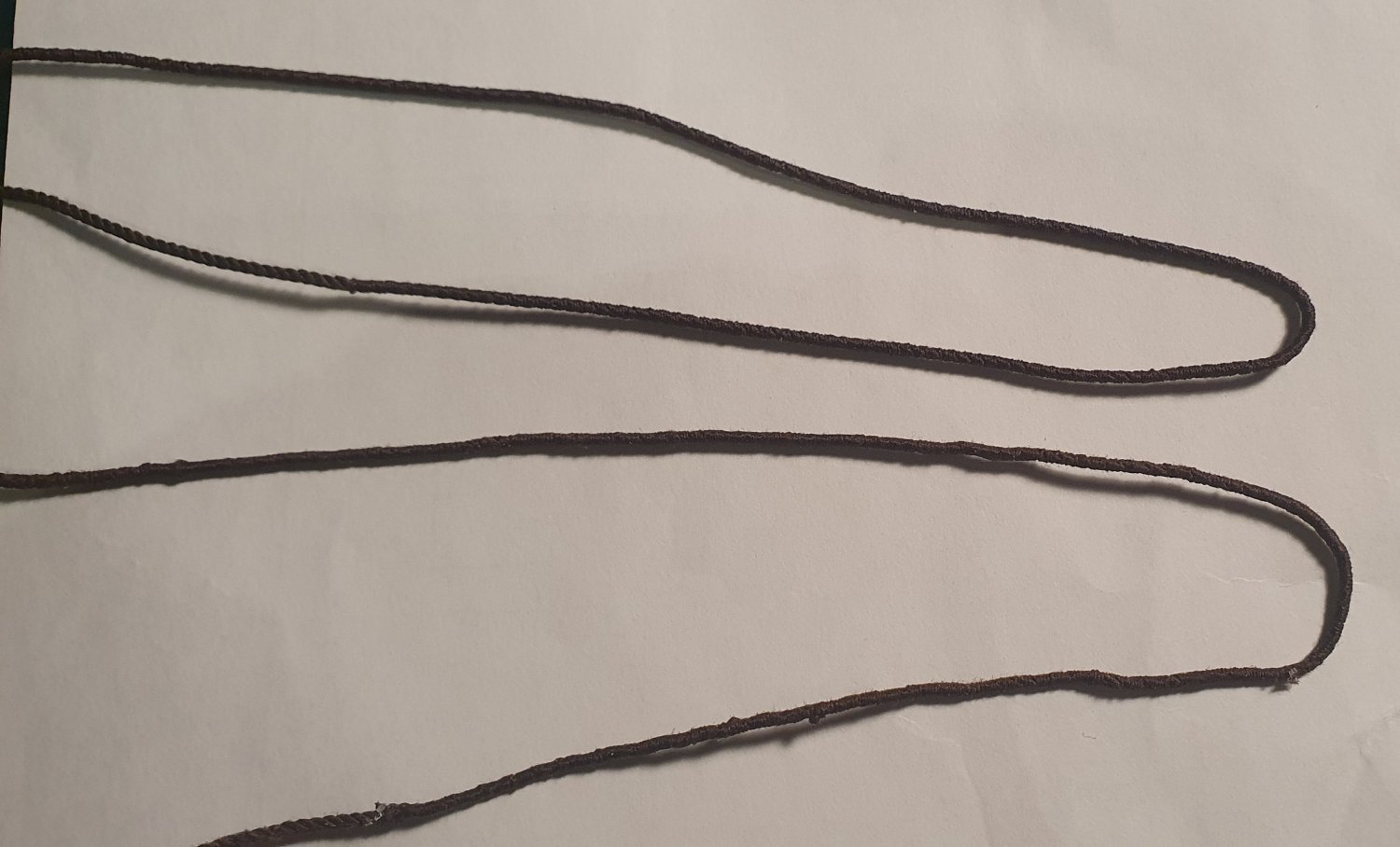
Thanks Dave. The rope is from Ropes of Scale. It is a big improvement on that included with the kit. Regards, David
-
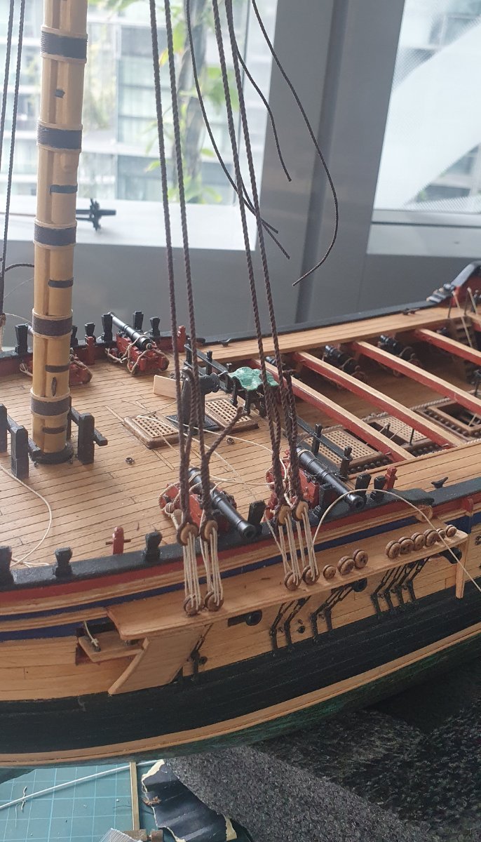
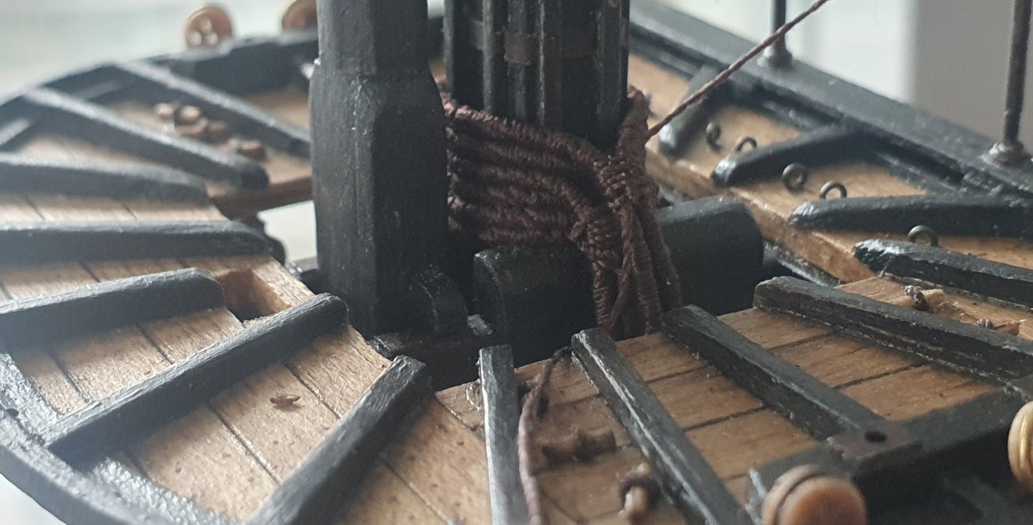
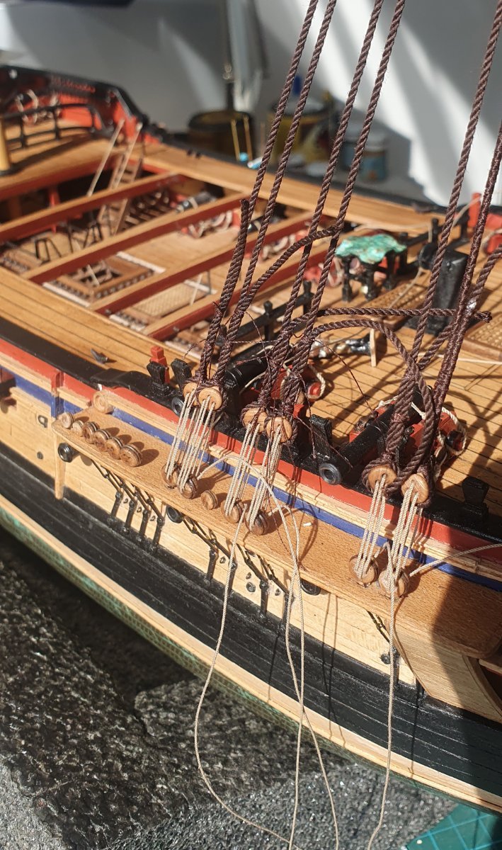
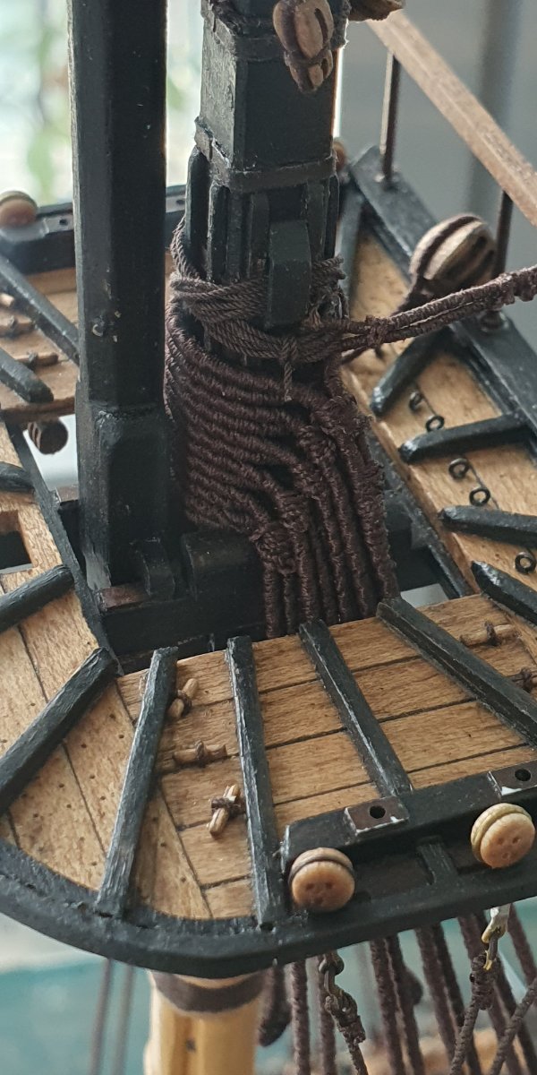
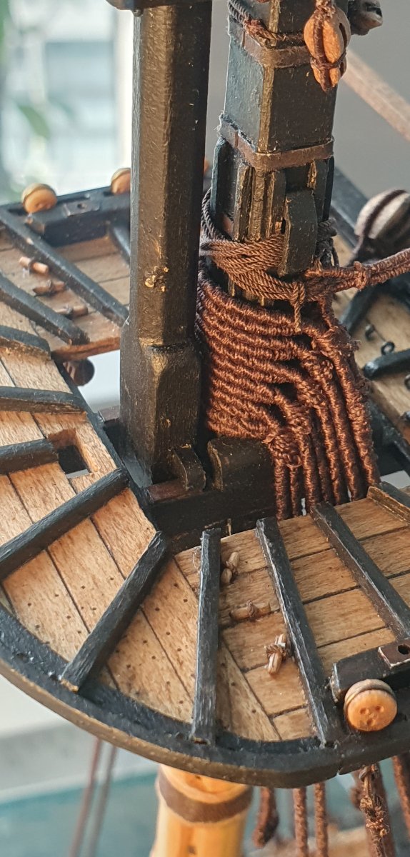
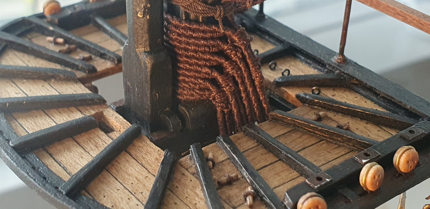
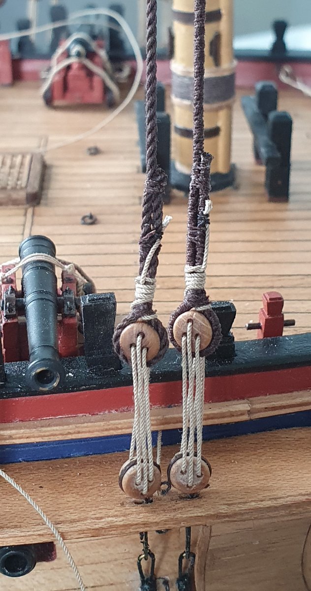
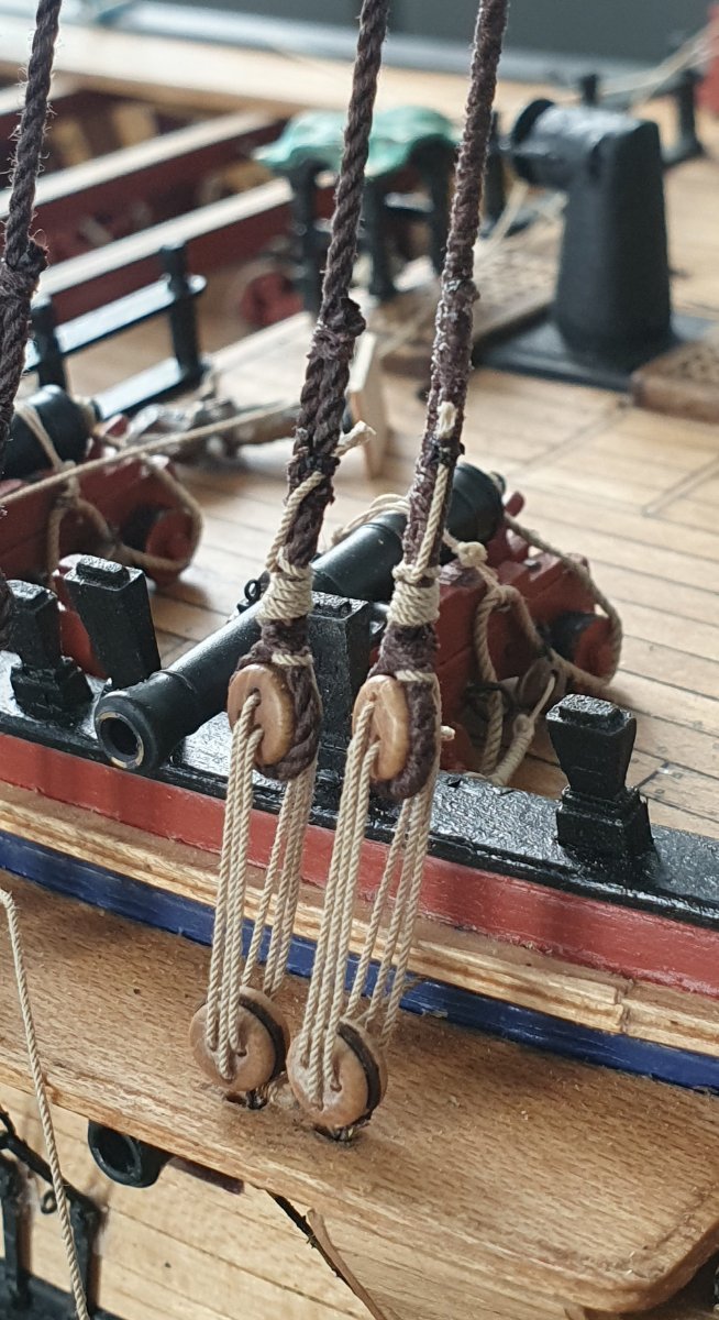
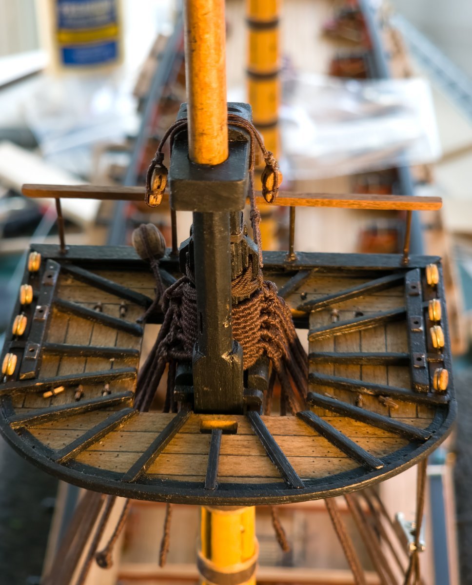
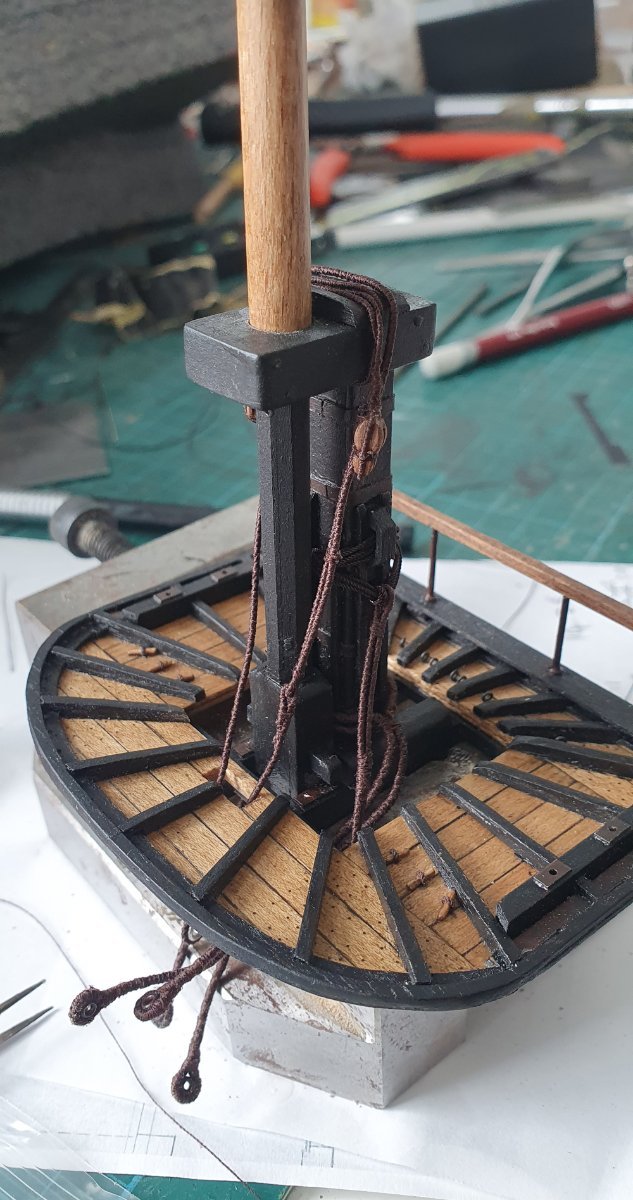
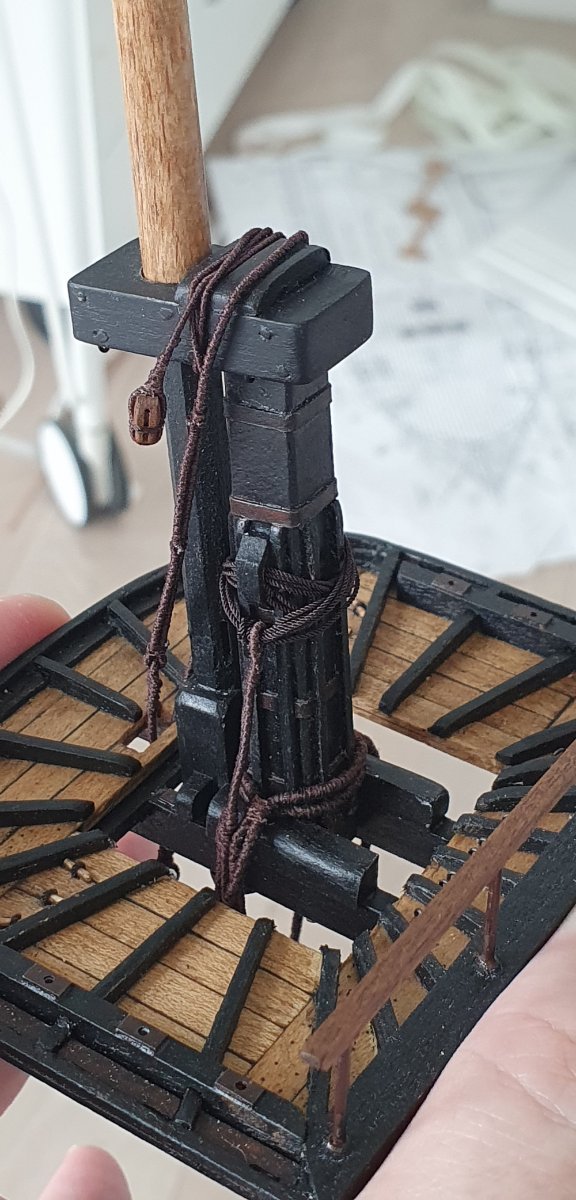
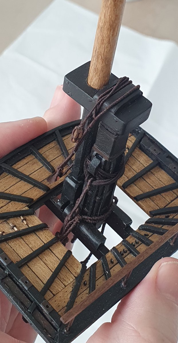
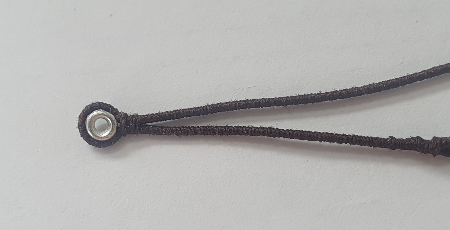
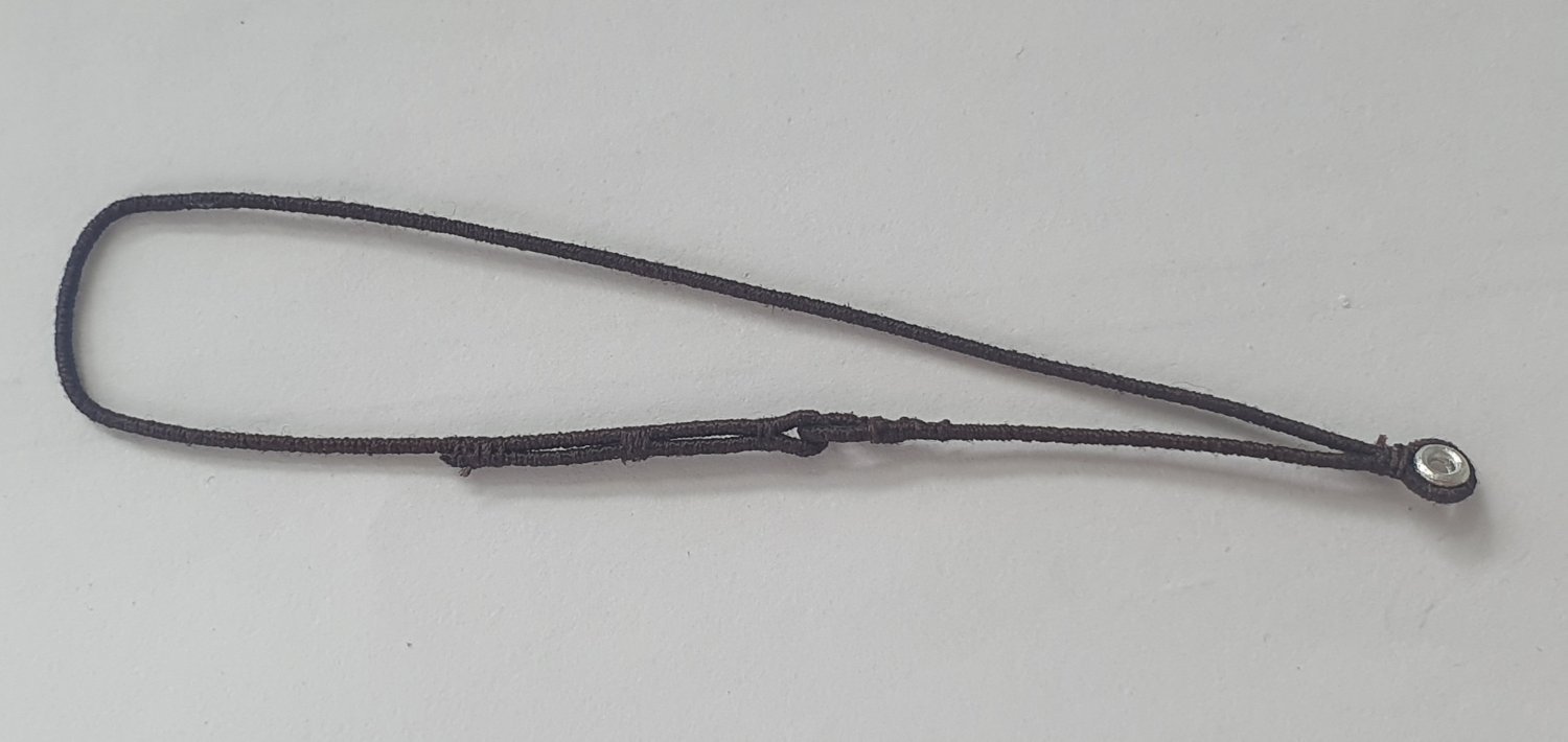
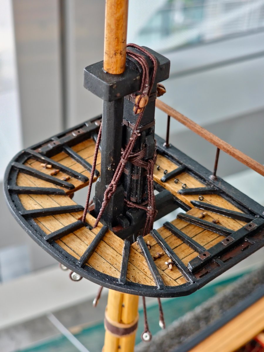
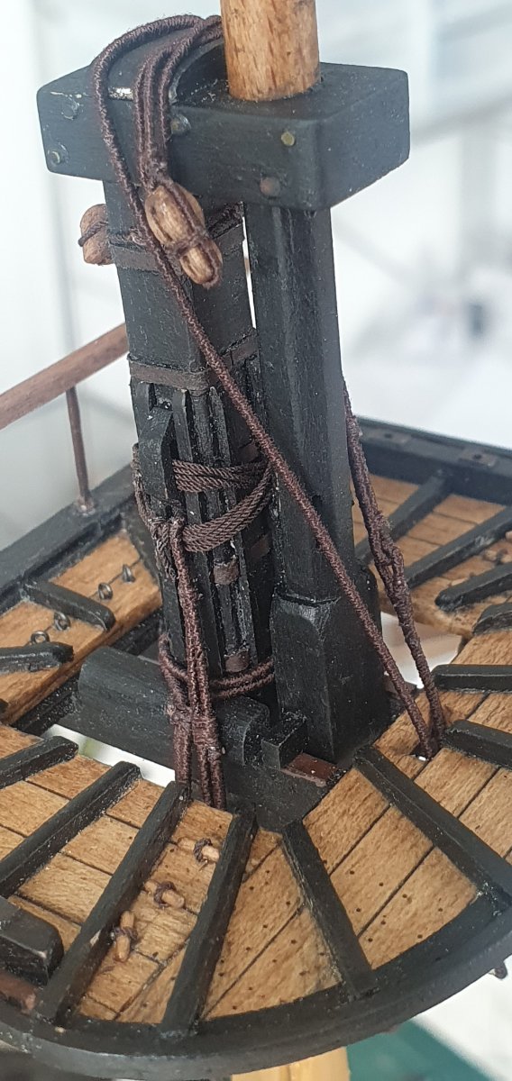
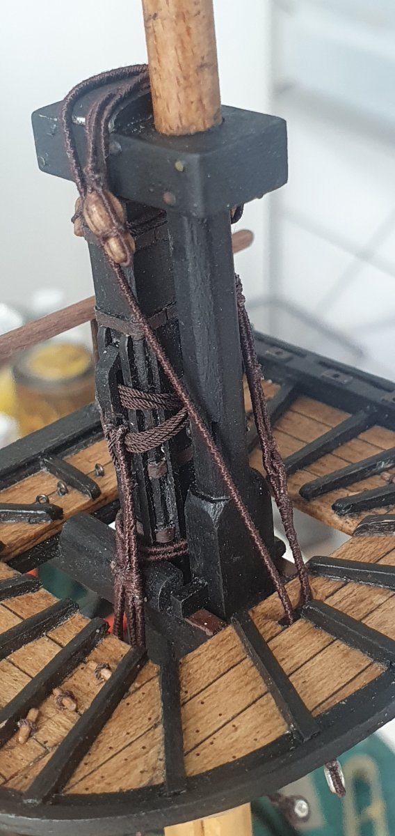
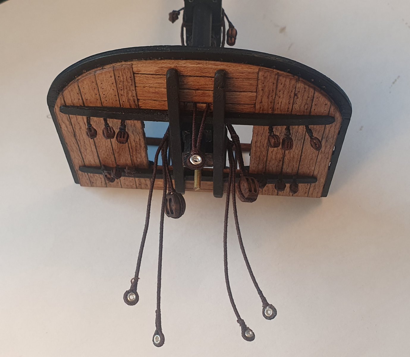
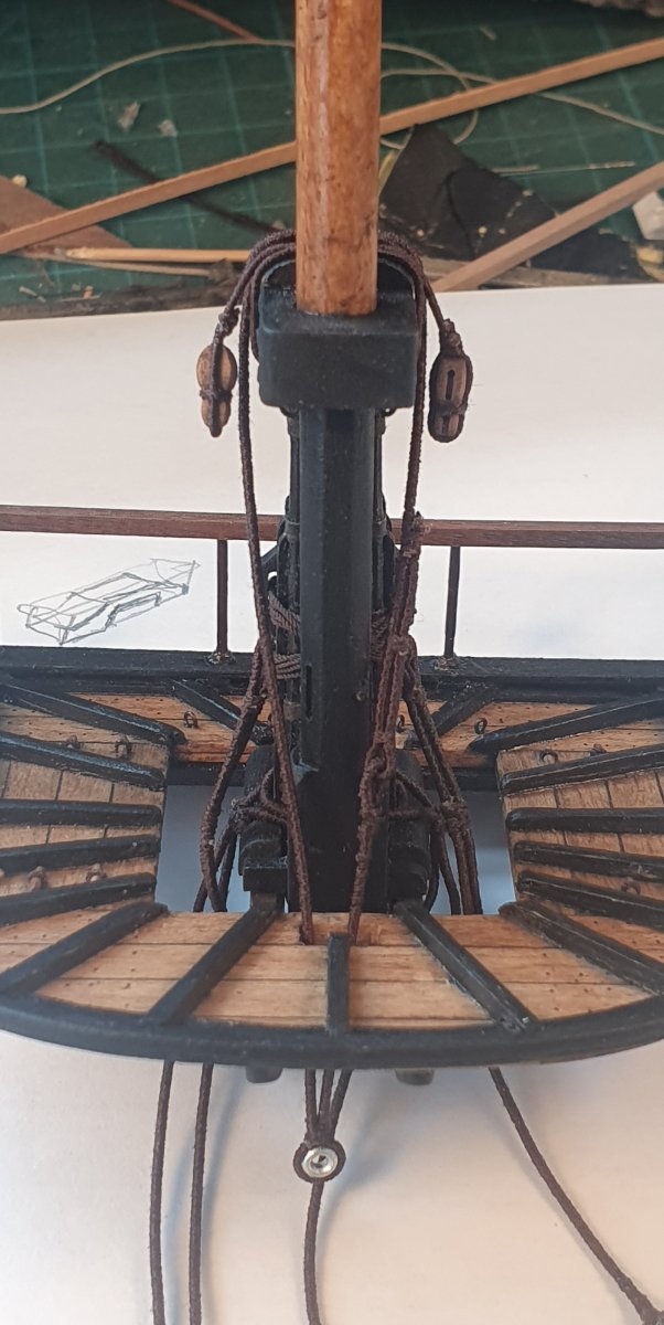
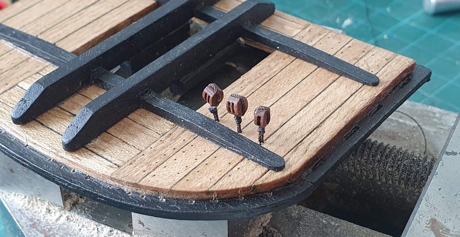
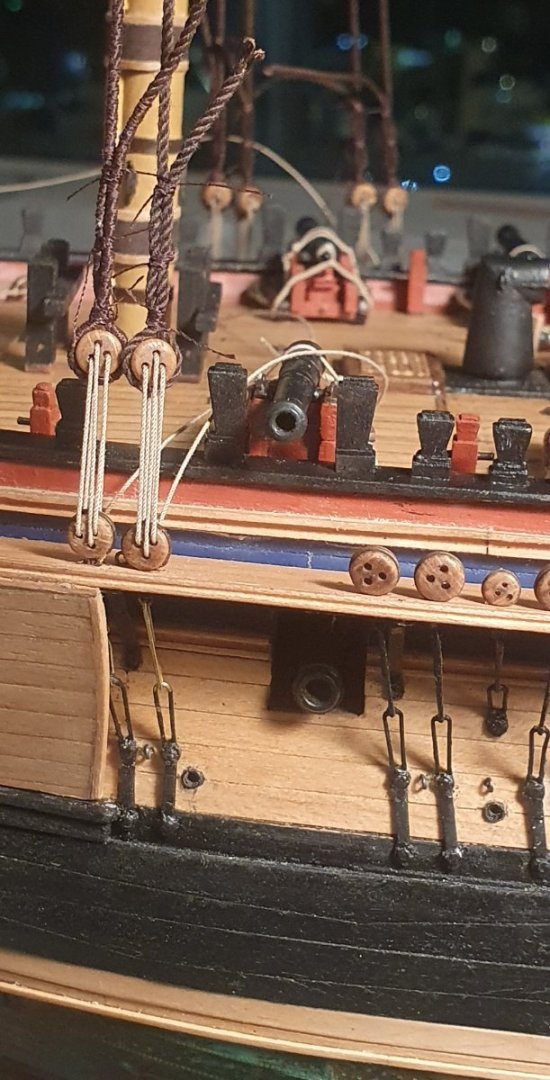
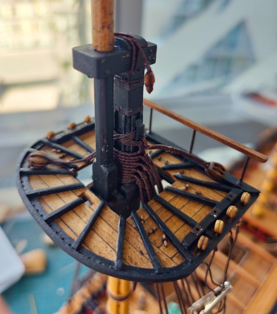
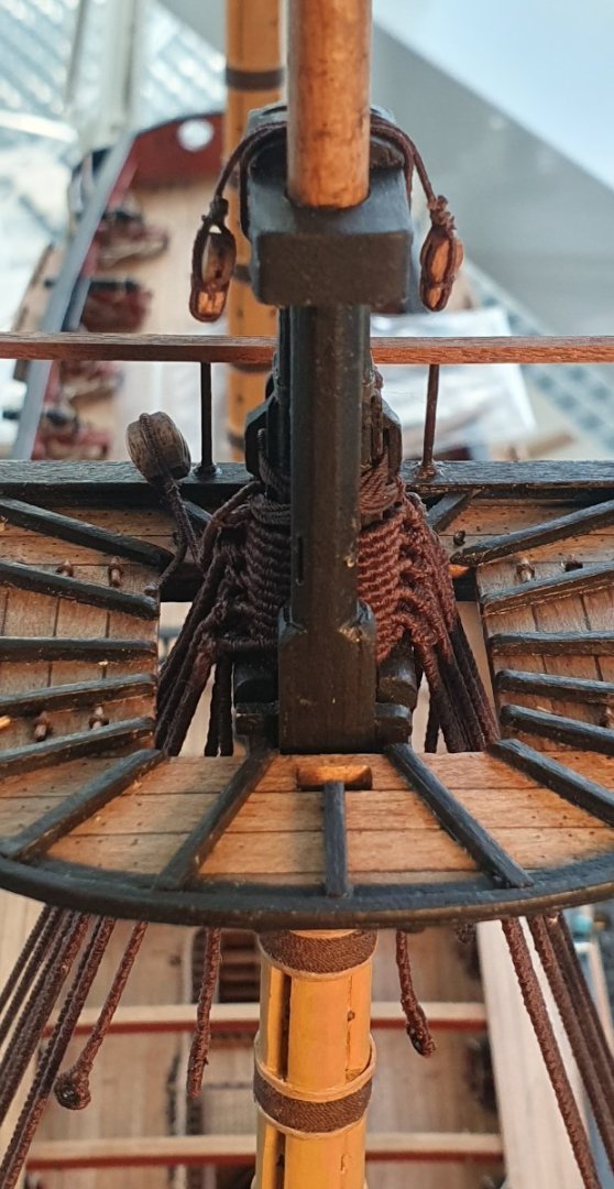
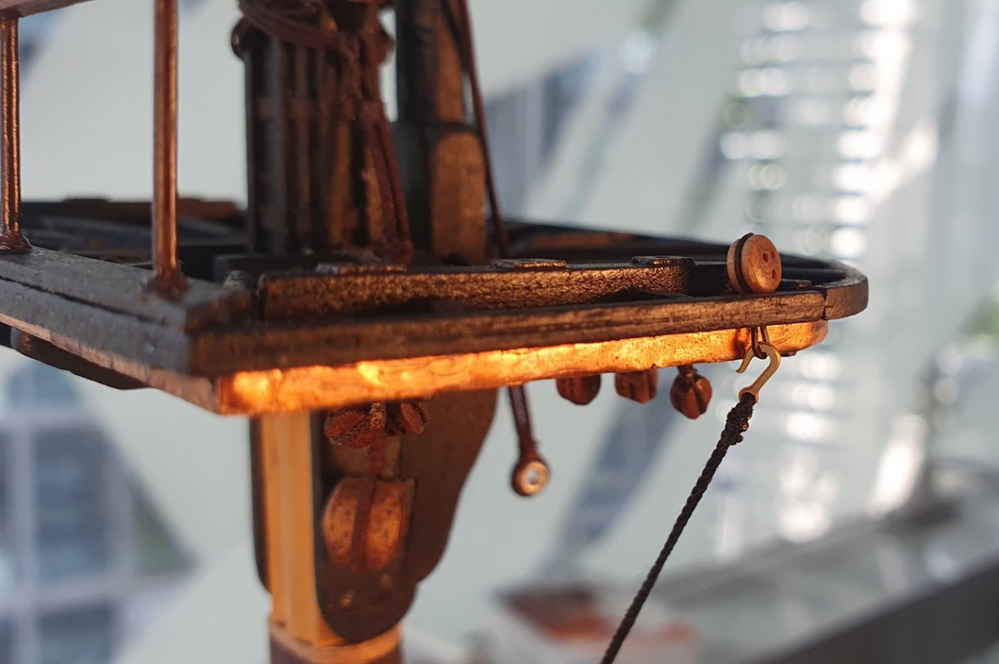
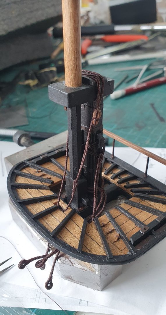
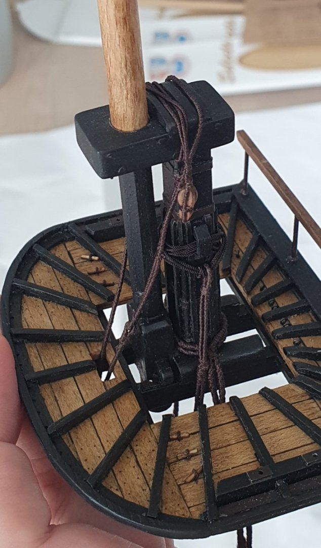
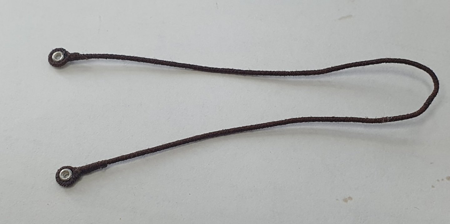
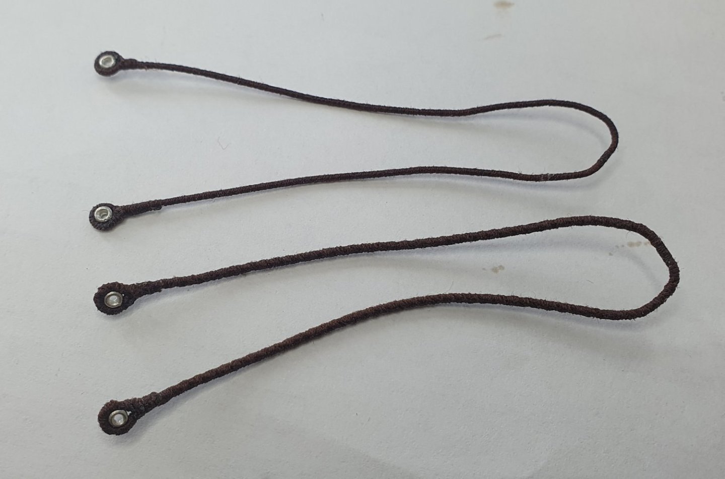
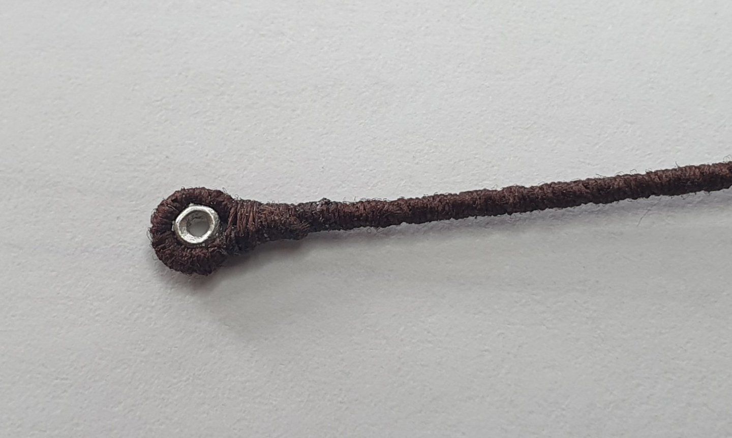
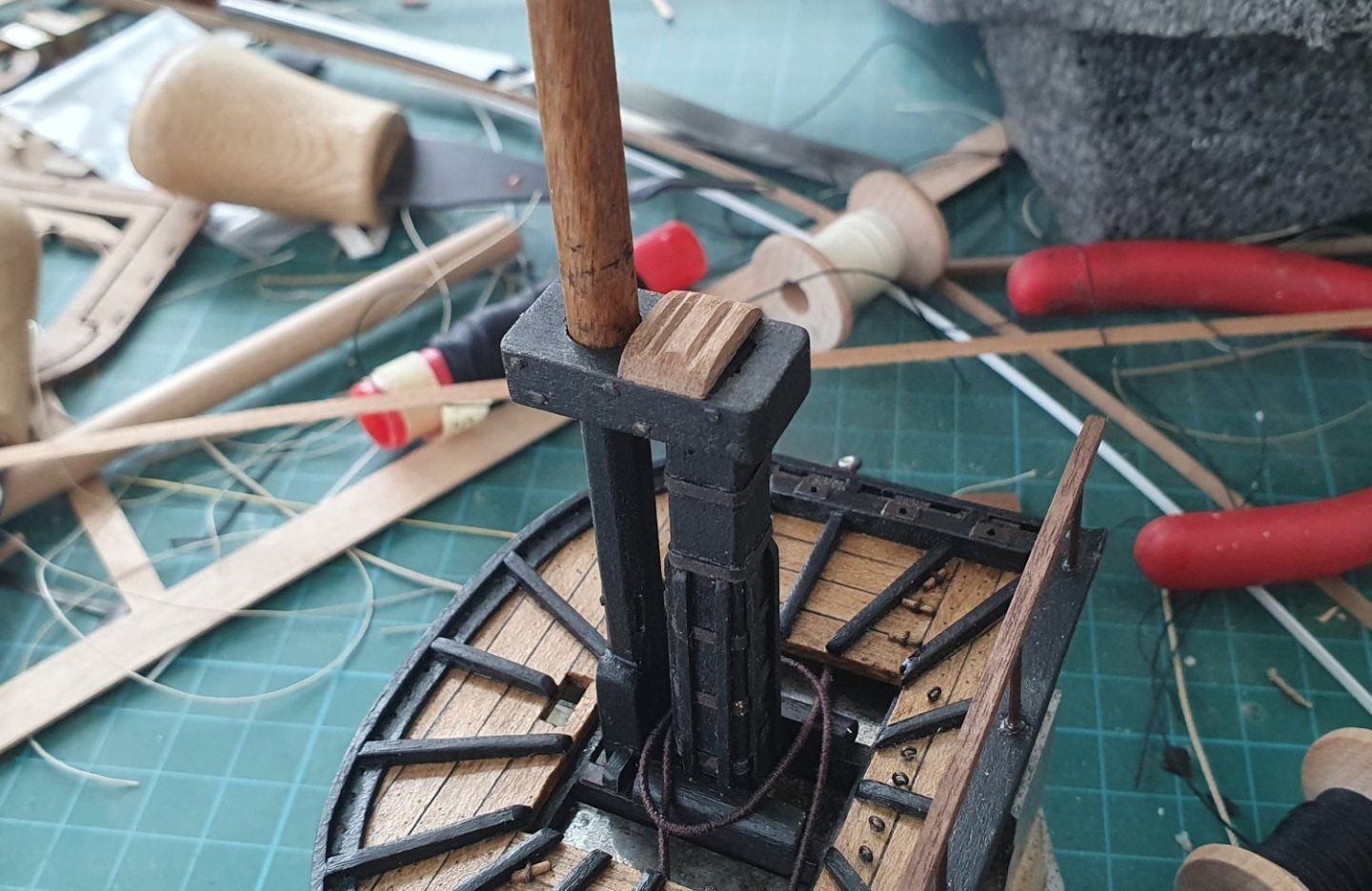
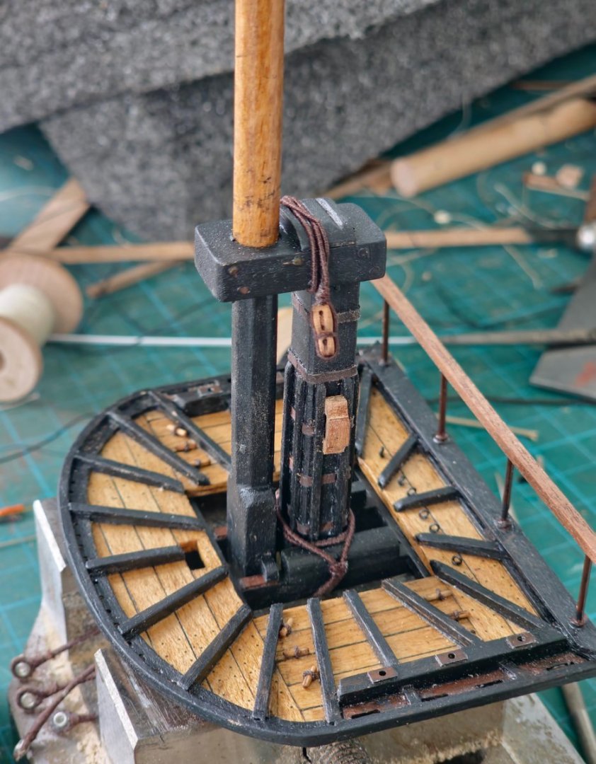
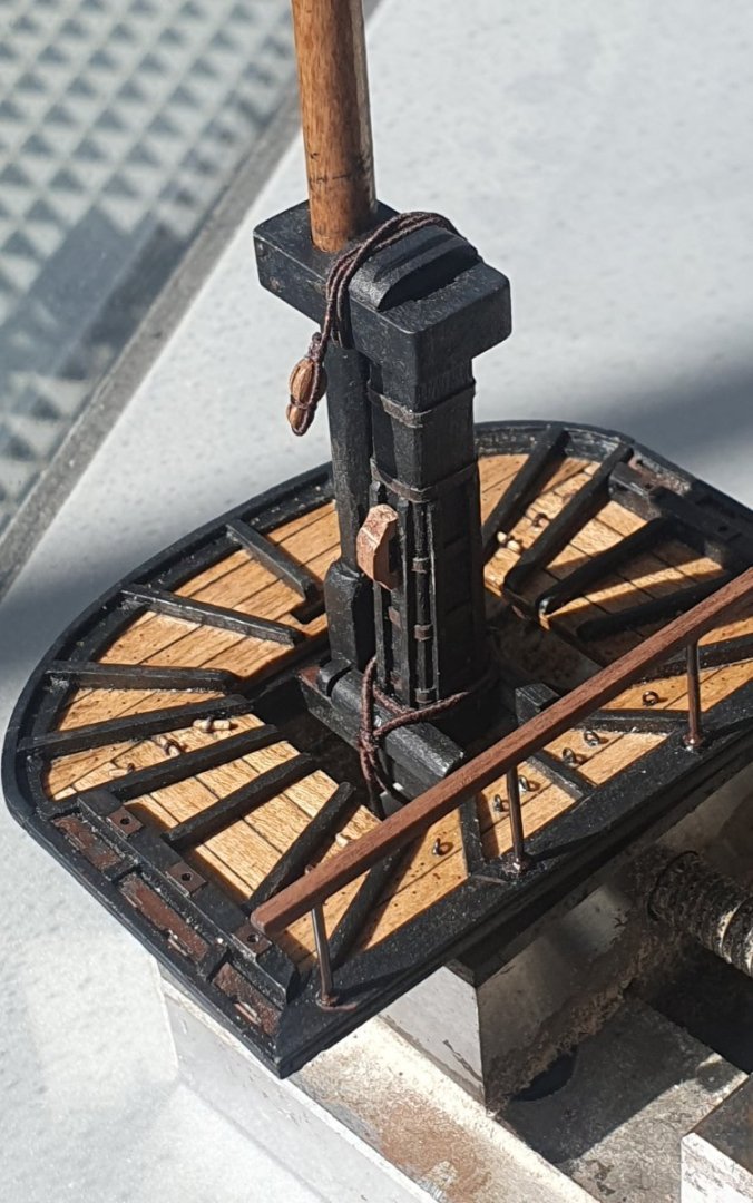
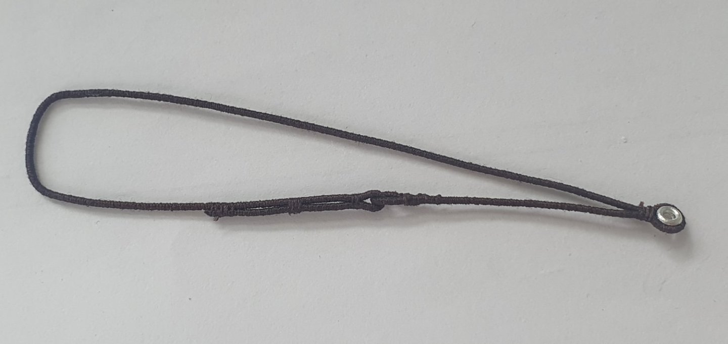
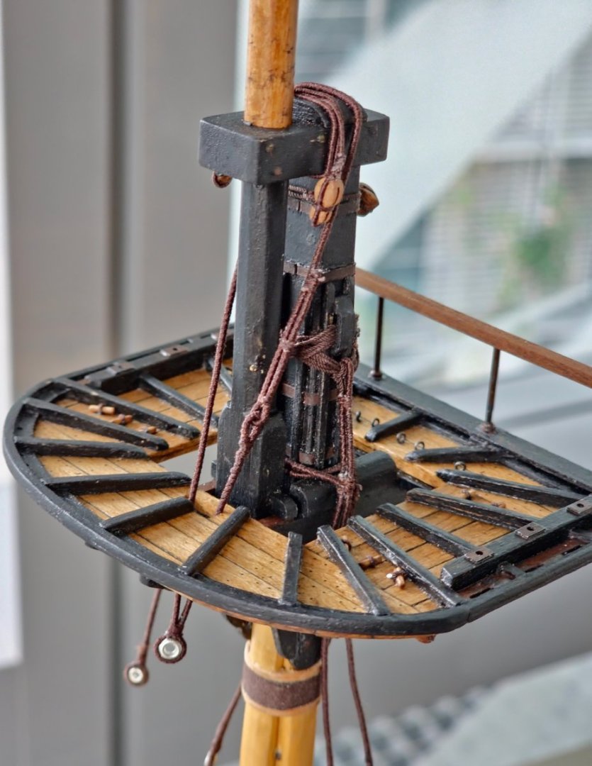
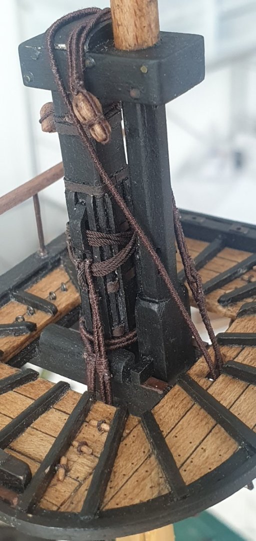
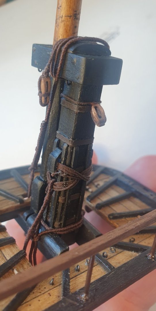
With great trepidation I started the rigging. I did some preparatory reading but that just led to more confusion due to the many contradictory positions. As this is the first 18th century ship I will be rigging I have decided to treat it as more of a training exercise to develop my technique. Pedants and sensitive viewers should probably look away now as I will be playing fast and loose with historical authenticity to make my life easier. First pieces to be attempted are the pendant tackles. First rigging, first contradiction. Two sources say two pairs in the fore and main masts with a single pair on the mizzen. Two alternative sources state all masts should only have single pairs. I am going with the former as I am not confident of achieving an acceptable splice for the single pair. I used 0.8mm Ropes of Scale dark brown for these that were served with some Gutterman thread. This was fiscally imprudent of me as they are served along their entire length so I could have just used an old shoe lace and none would have been the wiser. Still, I suppose it helps maintain dimensional consistency. I had some Bluejacket cast metal thimbles that I seized into the end and then fixed the assembly to the mast starboard first then port. I hung the aft tackle about 5mm lower than the fore which scales to about a foot in real life which is apparently the convention. After I had installed them, I realised that I had made my first bungle. According to Steel these should be the same diameter as the shrouds so I have subsequently remade them using 1.2mm diameter served rope although the photos still show the thinner ones attached to the model. I fashioned a top bolster out of walnut and scribed some grooves to take the lift blocks and sling. I then made a couple of cleats to take the lashing for the jeer blocks. These cleats are not the official Diana versions but ones borrowed from HMS Victory as I thought they would make my life easier when trying to keep the lashing in place. I seized a couple of sister blocks to the ends of some served line for the lift blocks. These were then wrapped around the lower mast cap in the manner shown in Lees. The jeer blocks were rigged with 0.8mm diameter served rope. I had initially gone with 0.5mm diameter but it looked to tentative. These were then attached to head using 5 turns of a 0.5mm diameter rope passing through the cleats. I used a 5mm single block lashed to the head to take the main topmast stay. Looking at the rigging diagrams this appears to be a 1.25mm diameter rope. I do not think that I can open the sheave enough to take this diameter so I will probably have to substitute this for a bigger block. The sling was made using 0.8mm diameter served rope. I used a slightly larger Bluejacket thimble for this one and formed the lashings as per the diagrams in Longridge and Lees. I have yet to get around to painting all of the thimbles. I guess I should get onto the shrouds now. I should have done those first but I found it easier to get this other rigging on before the tops were fixed to the model.


-
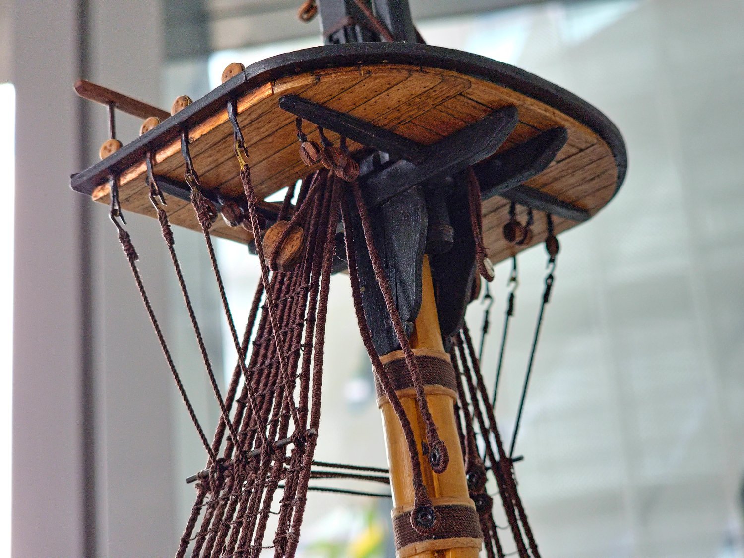
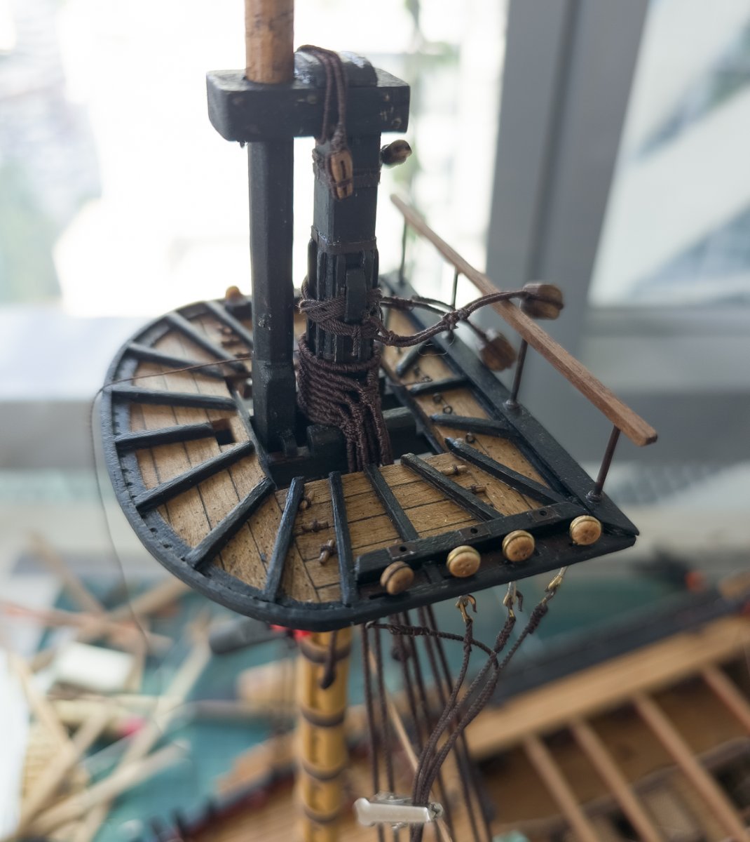
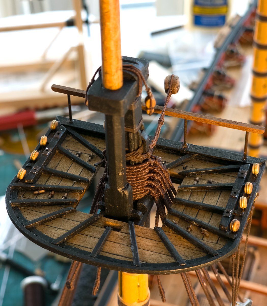
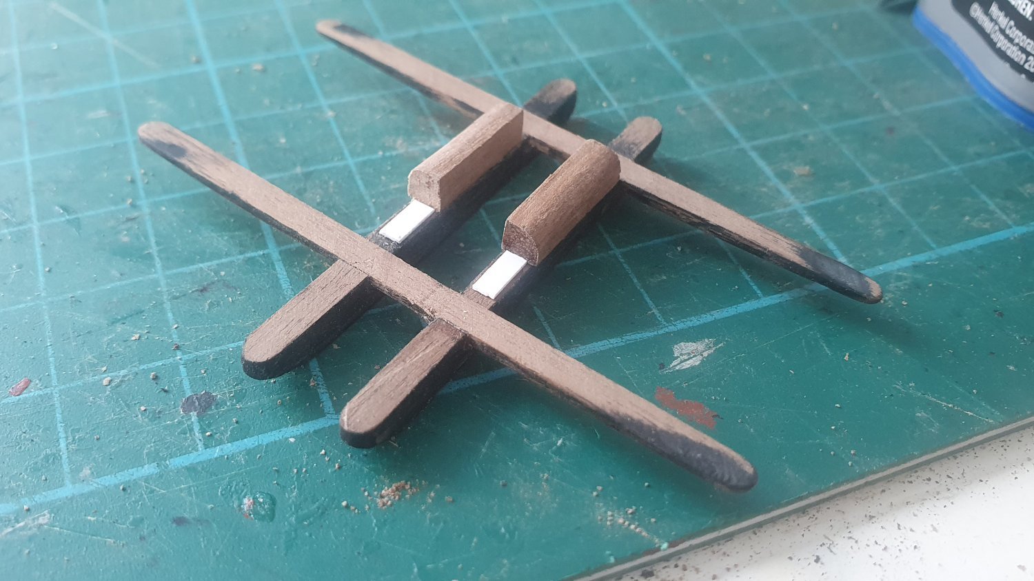
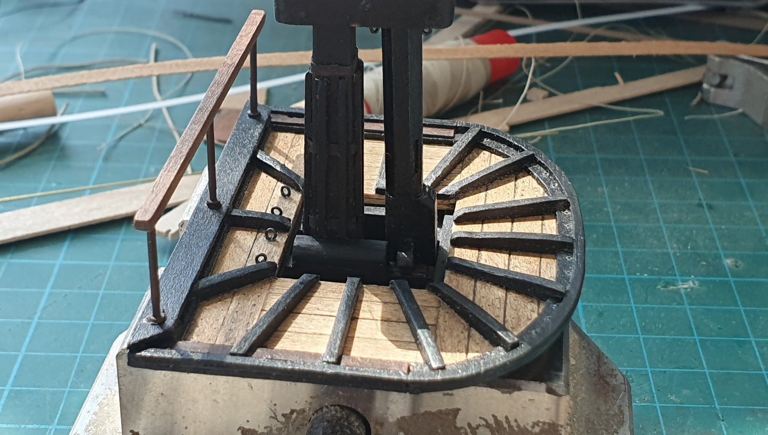
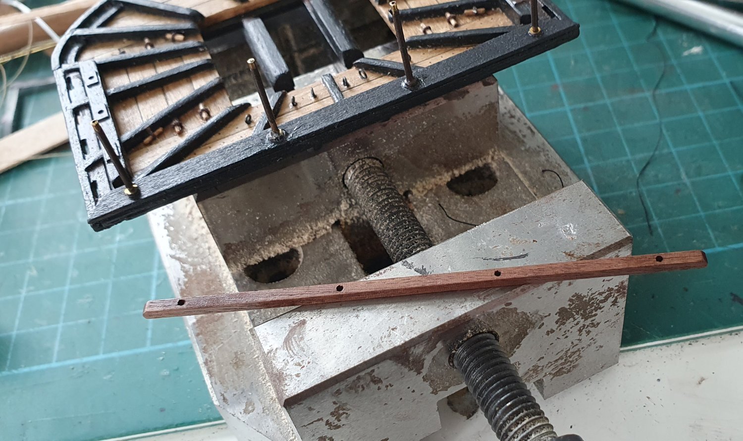
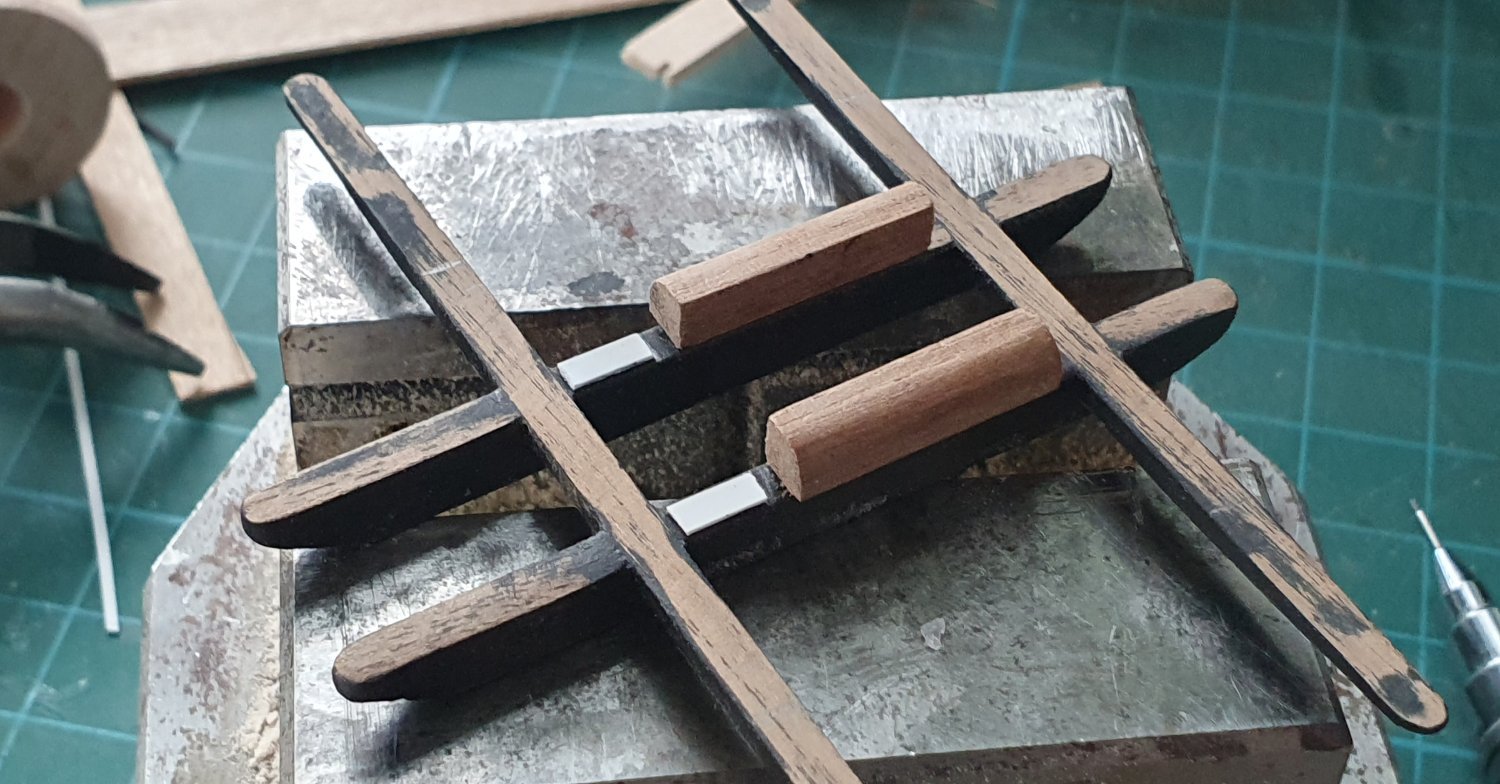
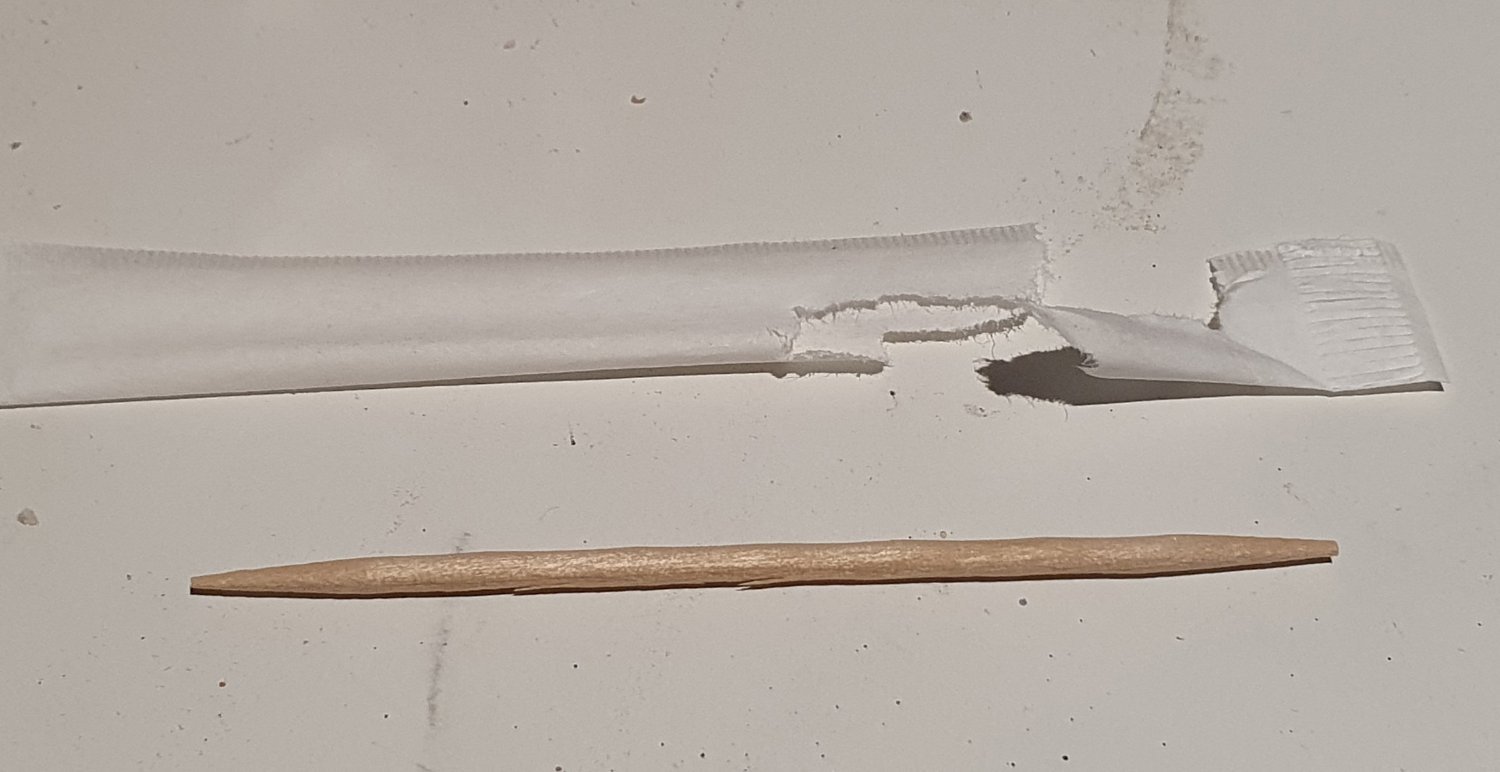
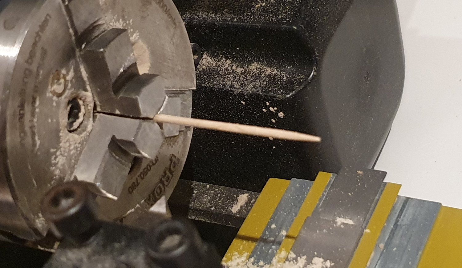
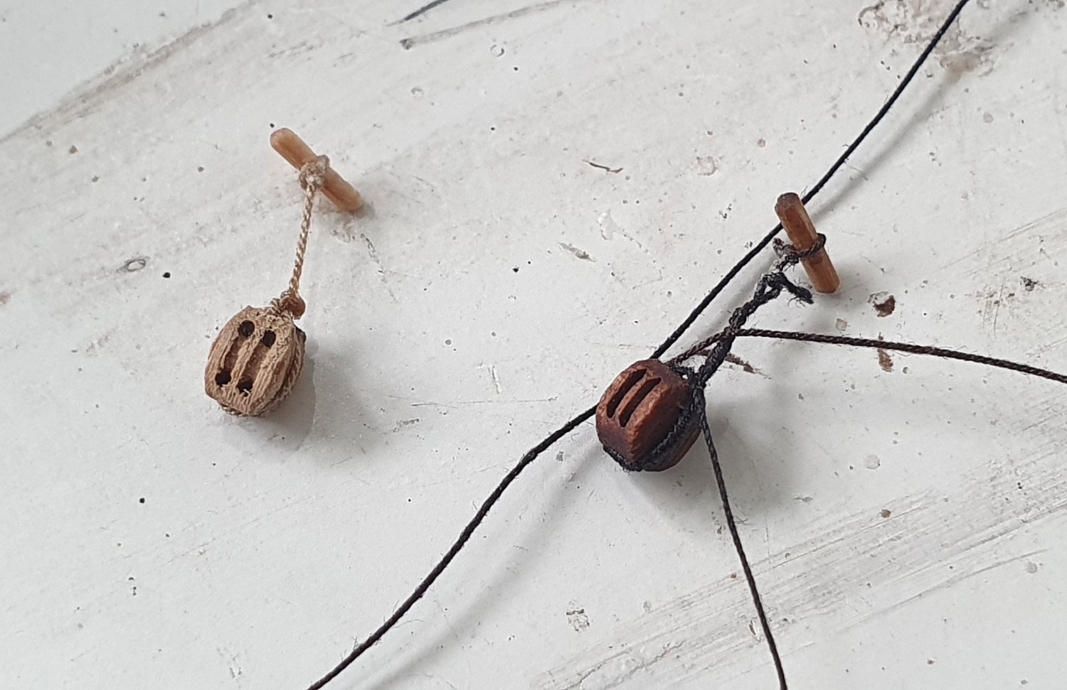
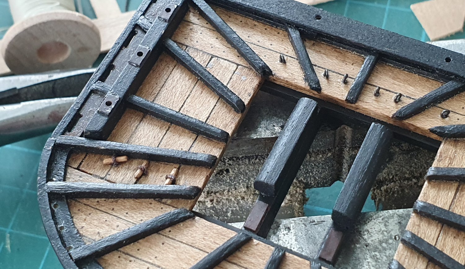
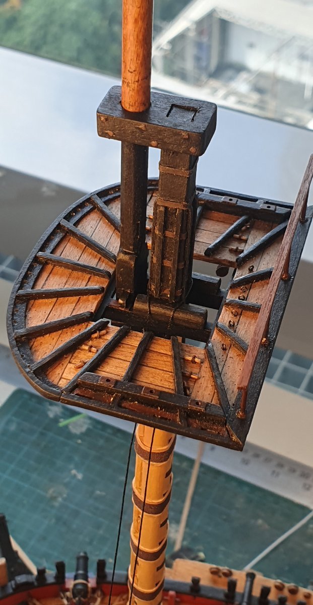
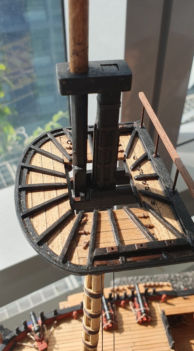
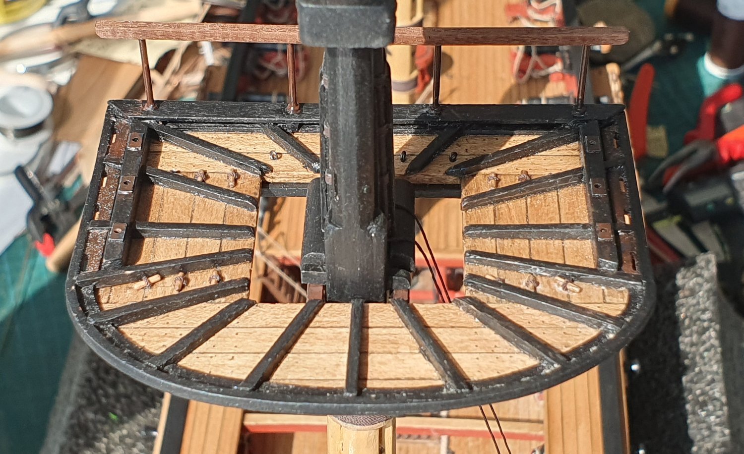
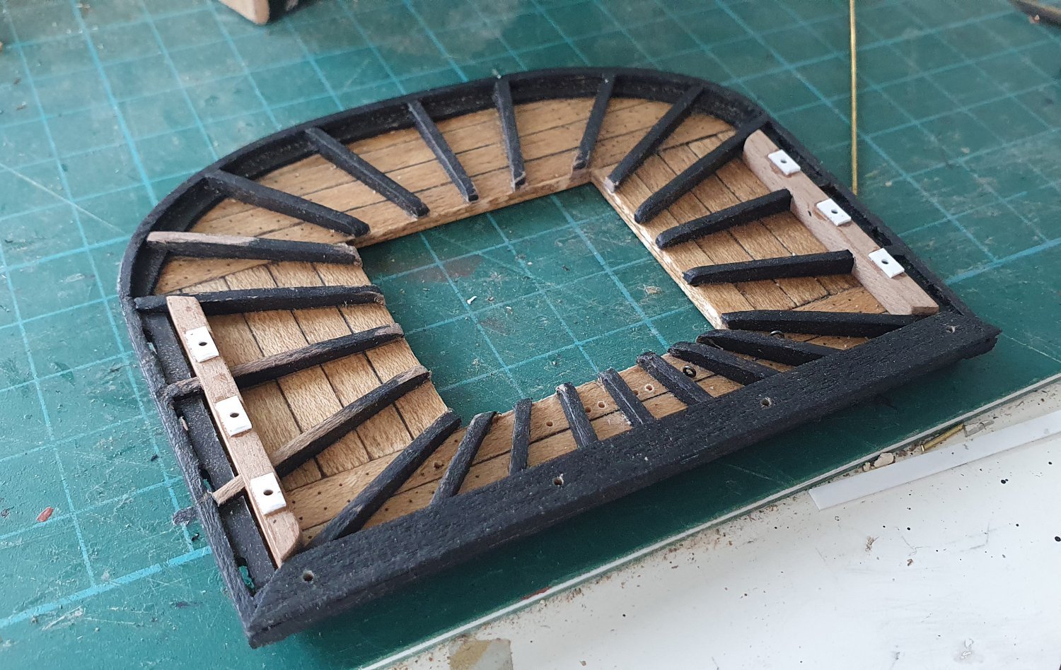
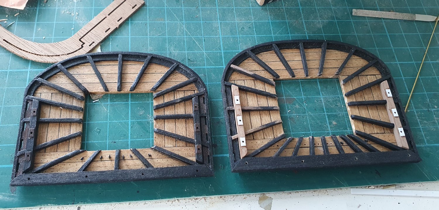
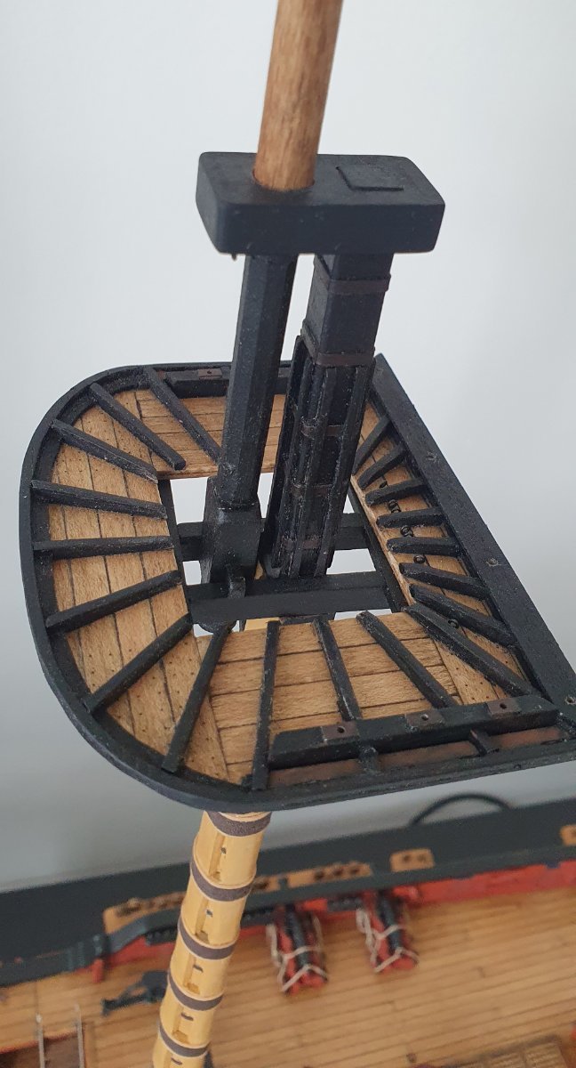
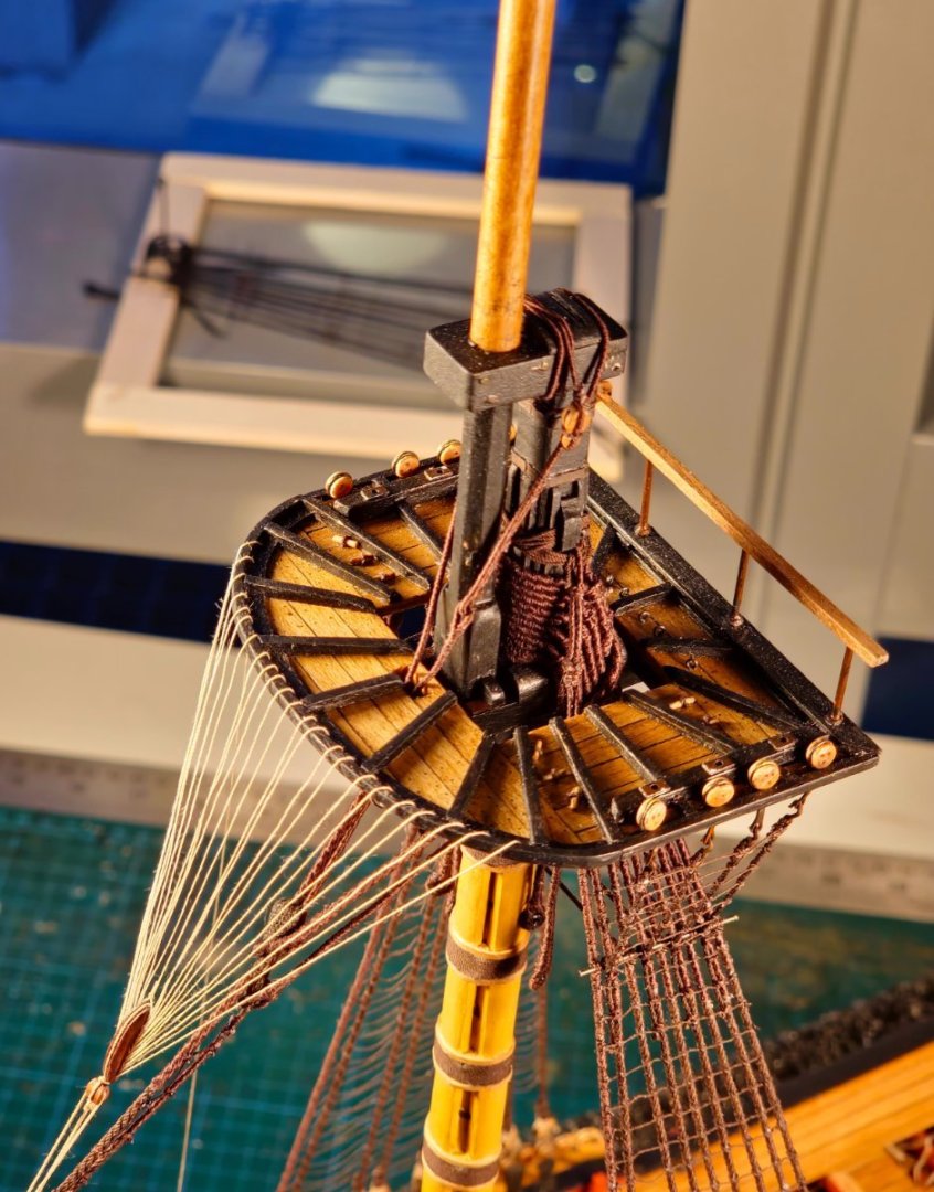
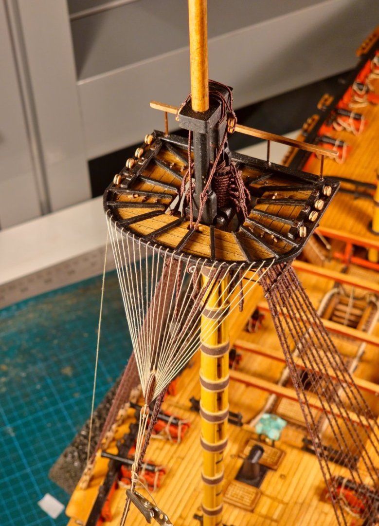
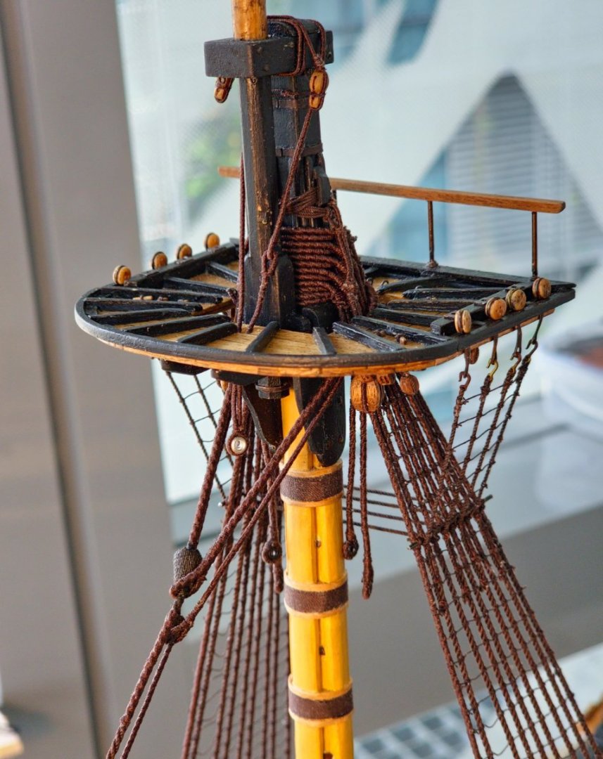
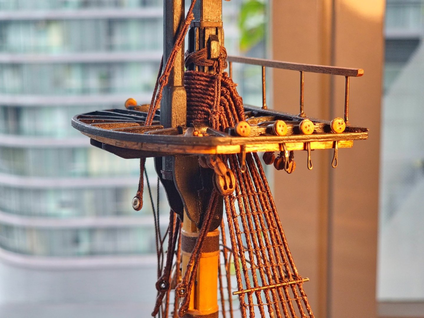
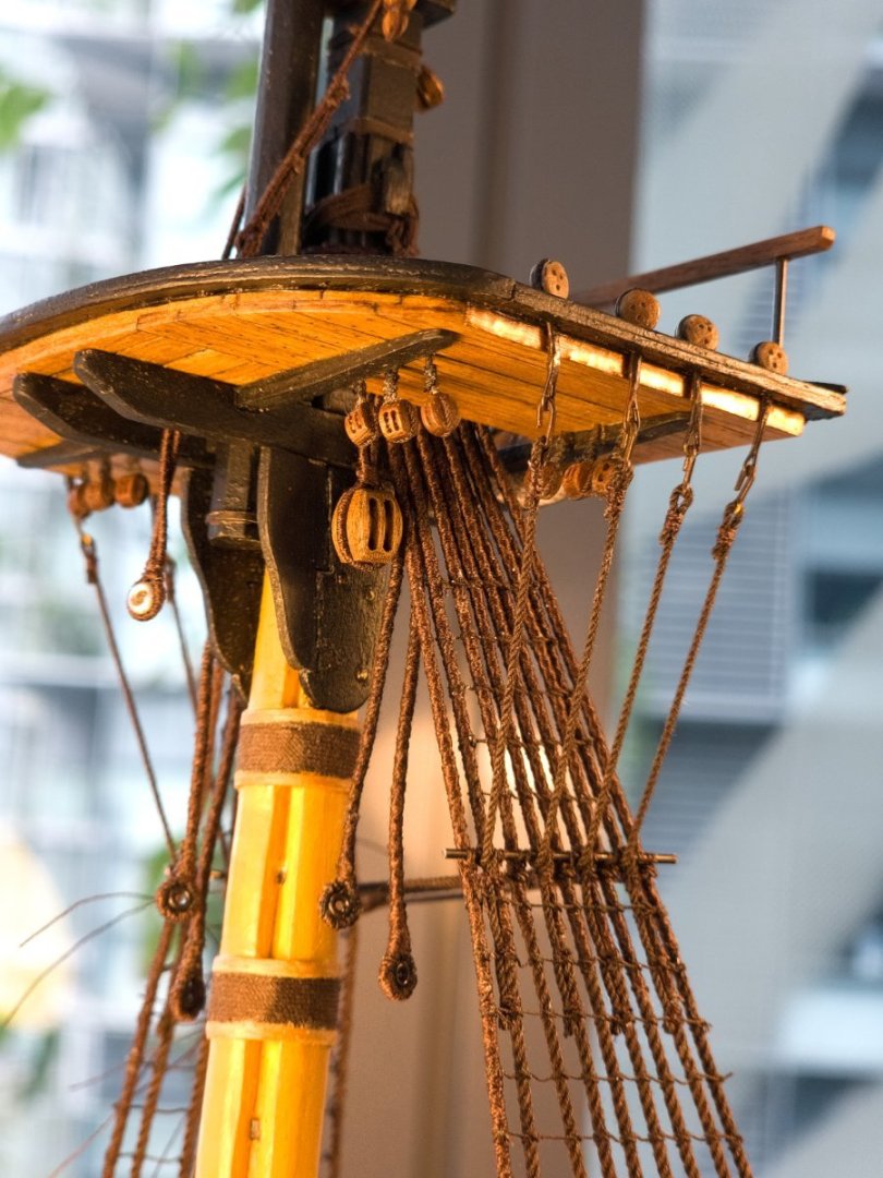
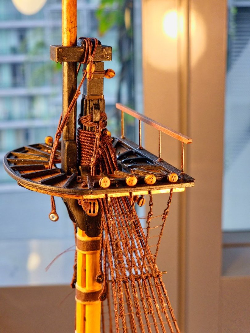
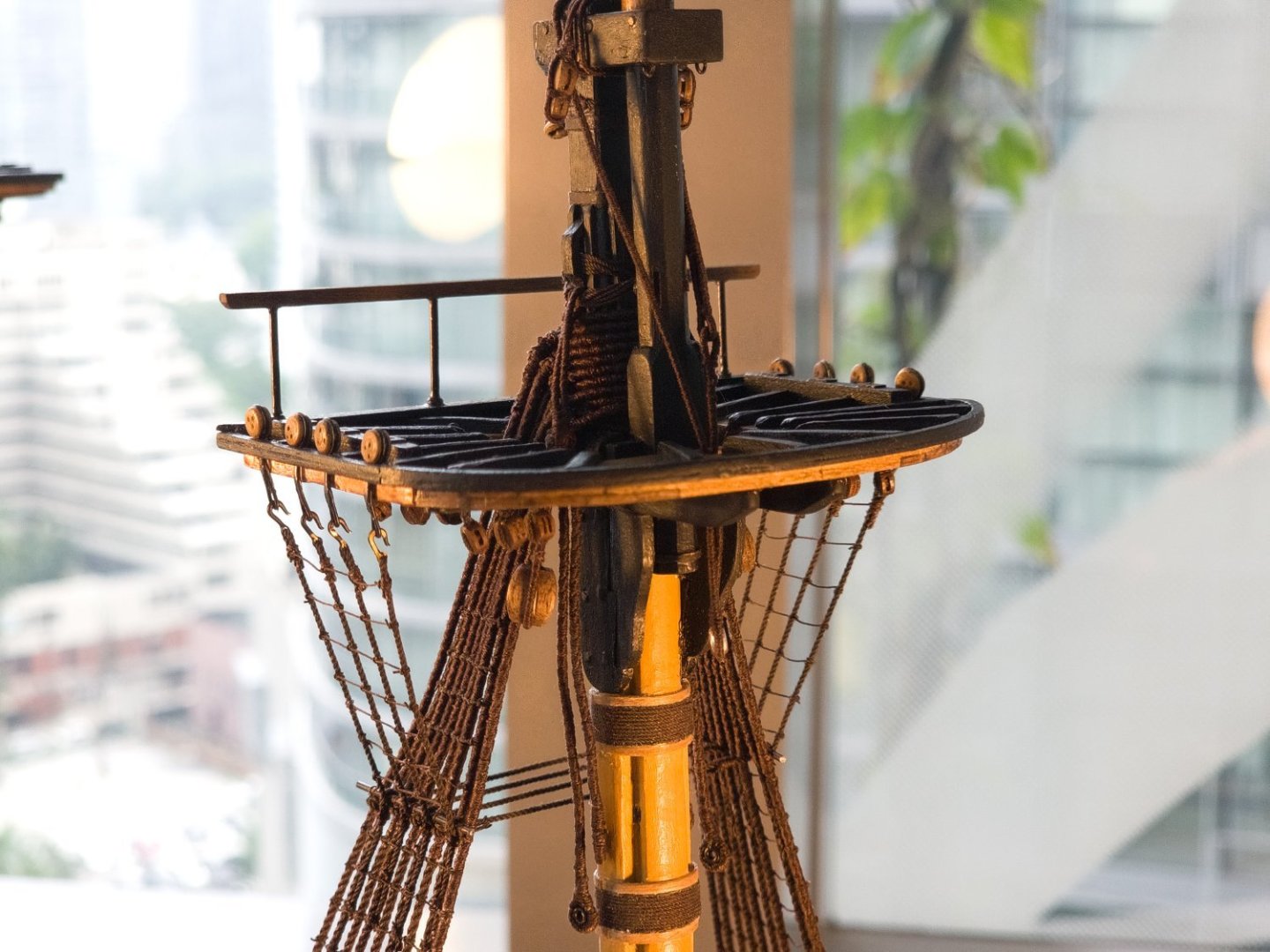
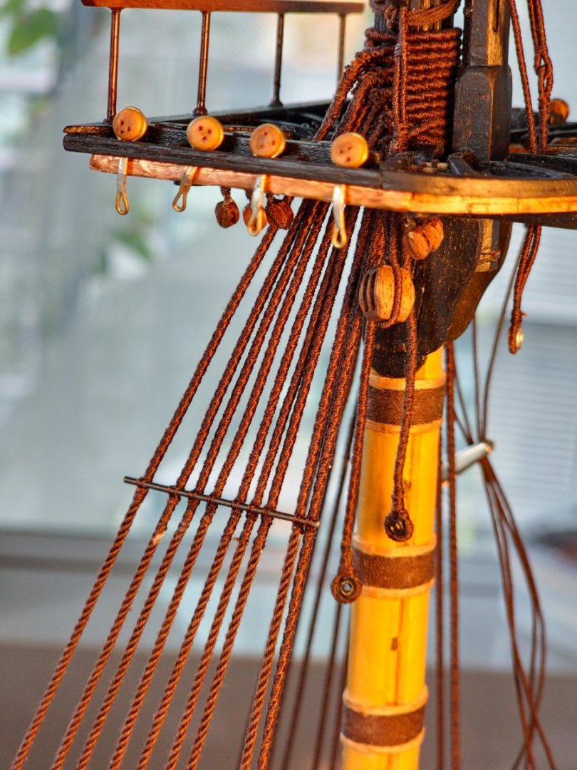
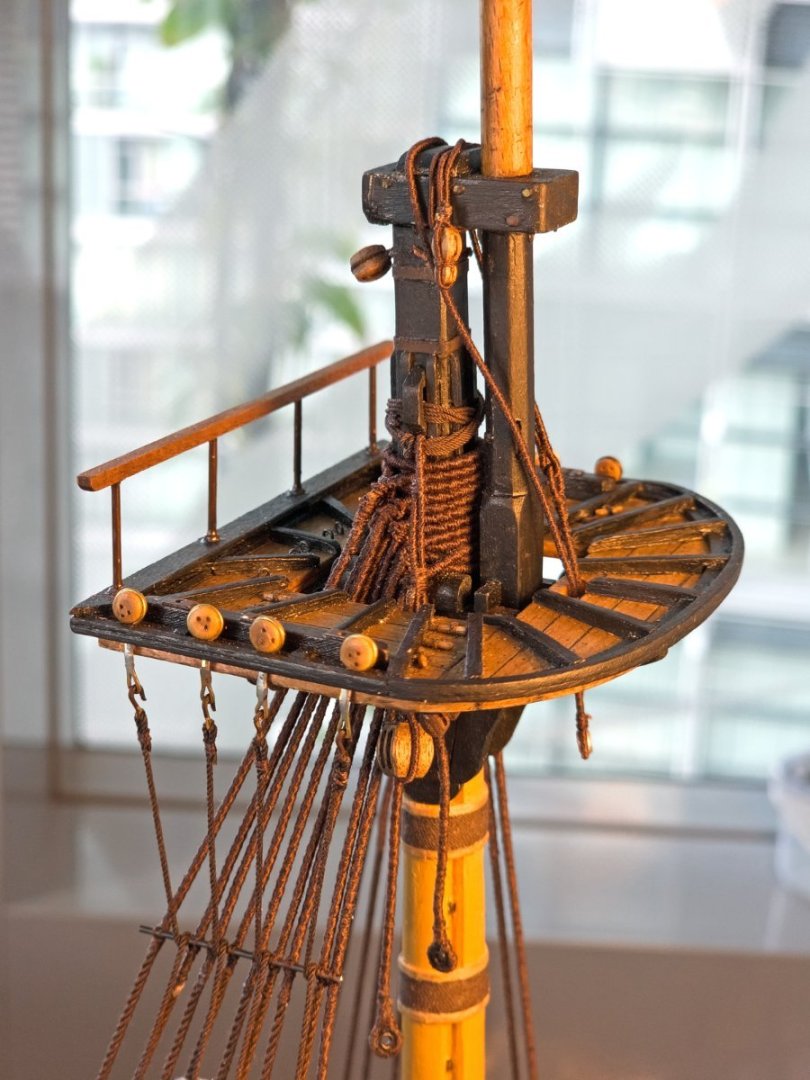
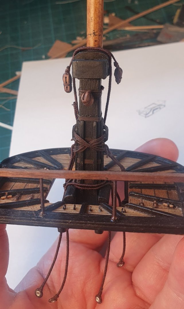
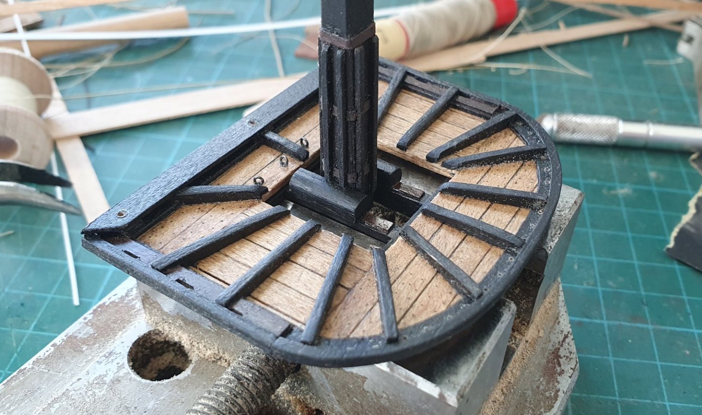
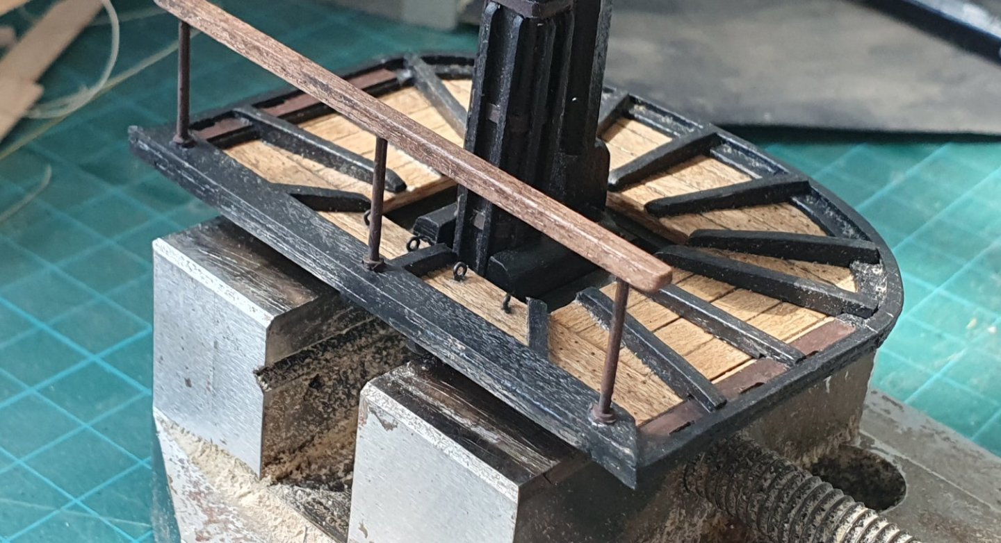
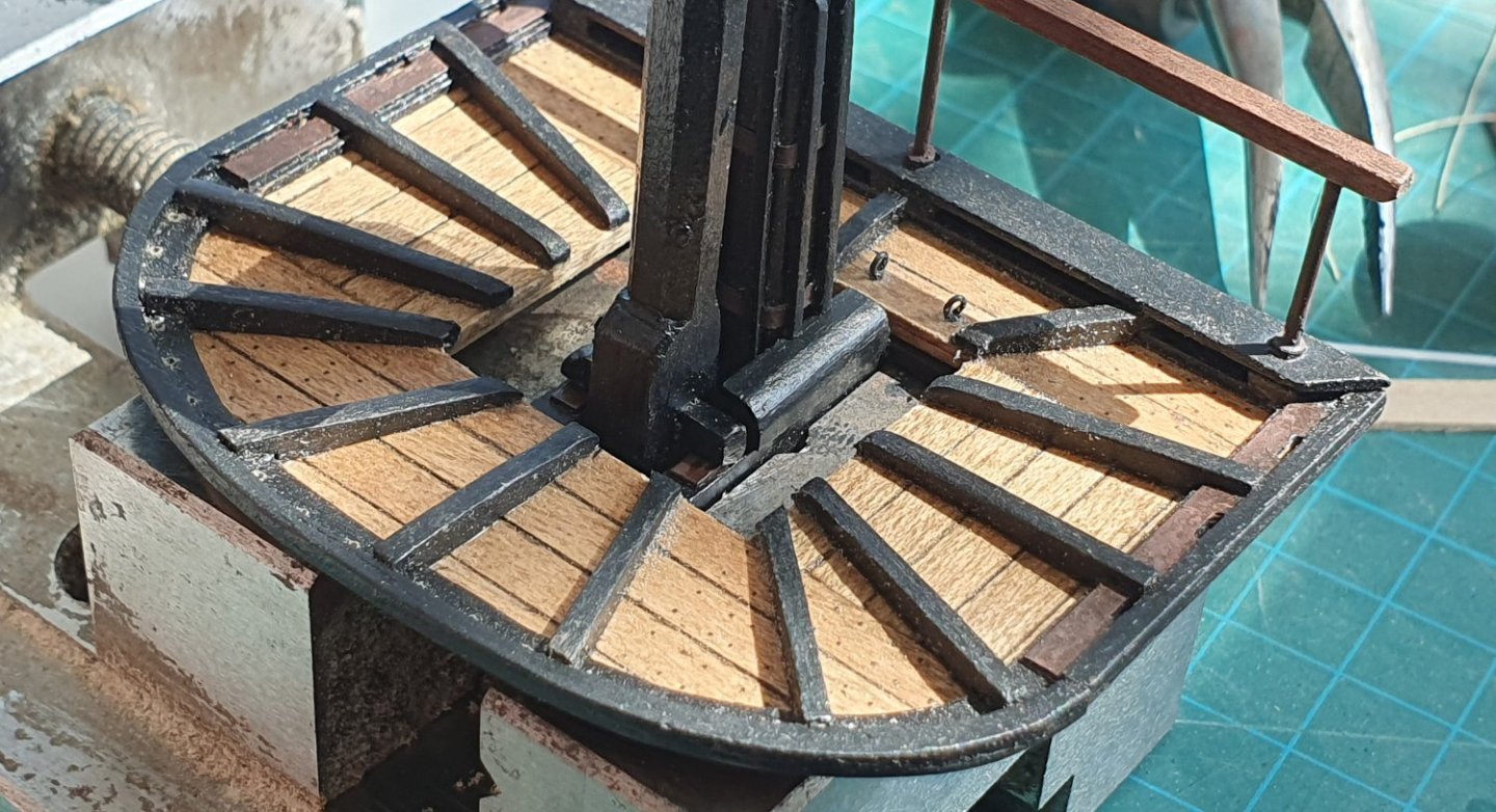
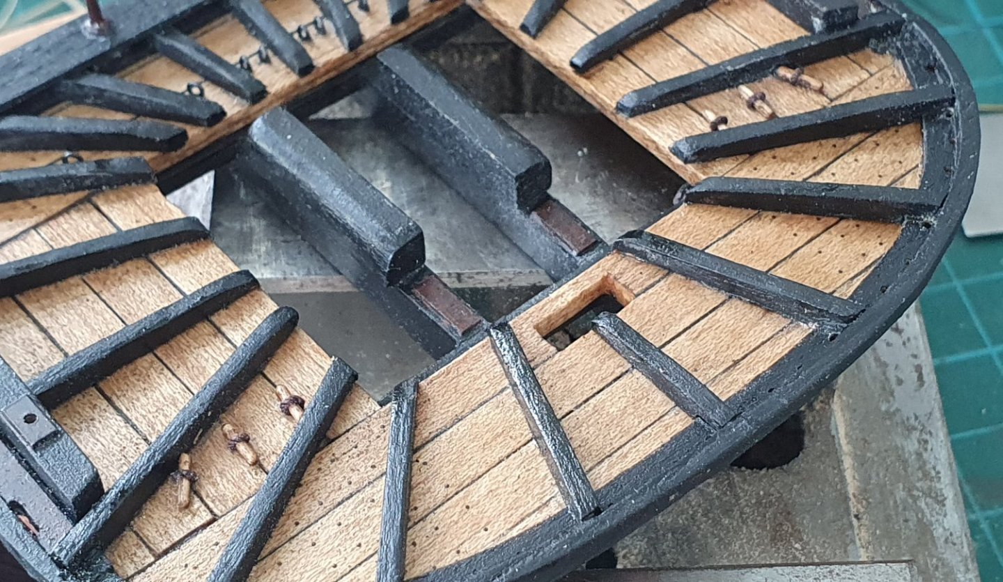
In preparation for the commencement of the rigging phase, I had to complete the tops and secure them in place. Despite spending what seems like an awfully long time working on the tops they are not quite finished yet. I still had to fix them to the cross trees. I then had to add some detail to each of the cross trees consisting of the bolsters and the metal plates for the fids to rest on. The bolsters were formed out of some nominally square section walnut to which I introduced a radiused corner using the dremel. These bolsters seem to be there to prevent the shrouds from rubbing against the cross trees. They cantilever out from the edge of the trestle trees slightly. Just enough to make it look like shoddy workmanship but that is how they are meant to be. The metal plates for the fids to rest on are just some styrene. Probably a tad thick but they will be more or less invisible once all the rigging is in place. I added the rail. I touched on the construction of this earlier but it was now time to glue them in place. A bit of an exercise to get the holes for the rail to align with the verticals when there are four verticals that need to slide into the four holes at the same time. That was pretty much it for the mizzen top but the fore and main tops have some rigging blocks that had to be installed. The kit suggests that these should be attached to eyebolts located on the underside of the cross trees however I followed Longridge/Lees for these and used toggles to suspend them. The toggles were made from fancy individually wrapped toothpicks reduced in diameter by spinning them in the lathe against some sandpaper. I took these down from 2mm diameter to a diameter of around 0.85mm. I would have liked to go slightly smaller but at this size they tended to twist like barley sugar if you applied too much pressure with the sandpaper. I then drilled holes in the tops and installed them. The Caldercraft drawings show two single blocks and a double. The AOTSD show two doubles and a single but the rigging drawings look like one of the doubles could be a single. I decided to press ahead with two doubles as I vaguely recall Dunnock lamenting the lack of sheave slots when he was rigging his model. I struggled rigging these blocks. It was easier to do with the 0.25mm rope but the 0.5mm looked more the part however this resulted in oversize knots. I tried serving the 0.25mm rope leaving the end free for knot tying, which looked the business, but that was too much of a faff and with 18 of these to put in place it was not worth the stress. I eventually resorted to using the 0.5mm dark brown rope from RoS in conjunction with some sneaky CA. I then tried to disguise the gluey mess with a clumsy seizing. It does not look that pretty but given their location I am more concerned with the look of the toggles that will be the visible part. I am a bit nervous about how they will perform if I apply too much pressure when rigging but I will cross that bridge when I come to it. It was quite a tricky proposition getting those installed but I guess that is just a gentle introduction to the perils of the rigging stage. Before gluing the tops in place I had another look at the rigging drawings to see if I needed to install anything else and noticed that there should be openings in the tops to allow for the lower yard sling to pass through. These openings do not appear in the main drawings for the tops in either Steel, Lees, AOTDS or Caldercraft. They do get a mention later on in the rigging diagrams. It would be very easy to not notice this and install the tops and it would be a tricky exercise to cut these out once installed on the model. I initially went for two openings either side of the timbers but then reverted to a single slot which would allow me to fully complete the sling off the model rather than trying to lash it in place with limited access. I also noticed that I have to fashion a bolster to sit on top of the caps for the sling to sit on. I also have to add some cleats to the sides of the head to hold the lashing of the jeer block strops. There seems to be no end of fiddly details to these elements. I need to take a break and head out to the craft store to look for some brown thread for serving. The stuff I have on hand has too much girth to it.


-
Further clarification
-
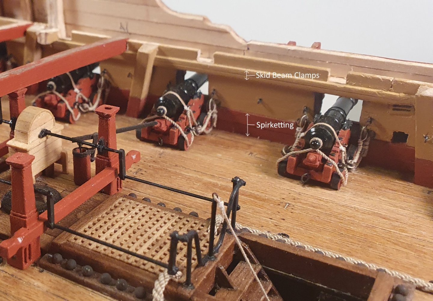
Hi Dave, I think that the ''decorative strip'' you are referring to is the skid beam clamp. This runs along above the gunports and provides further support for the skid beams. You can see this in the AOTSD book on page 61 drawing C7/2 item 5 and page 108 drawing G1/6 and drawing G1/7 item 10. Regards, David
-
Thanks Dave. I am going no sails. I had attempted furled sails on my previous build but I was not quite convinced by the end result. I am dreading the rigging stage though as knots are not my friend.
-
Thanks Jason. I do like the natural sunlight but unfortunately the sun only comes into the workshop early in the morning when I am usually fast asleep.
-
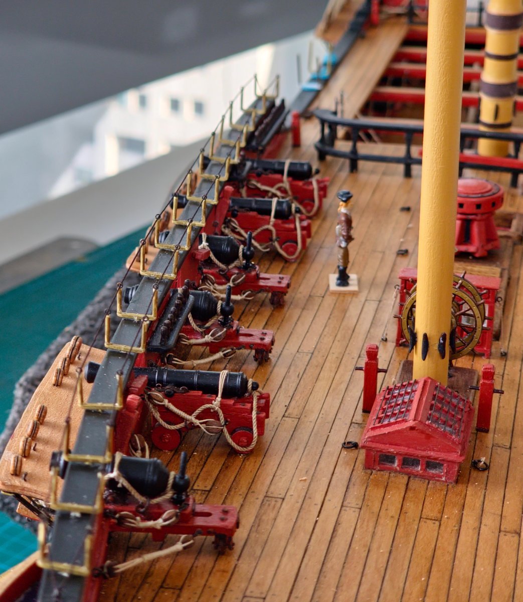
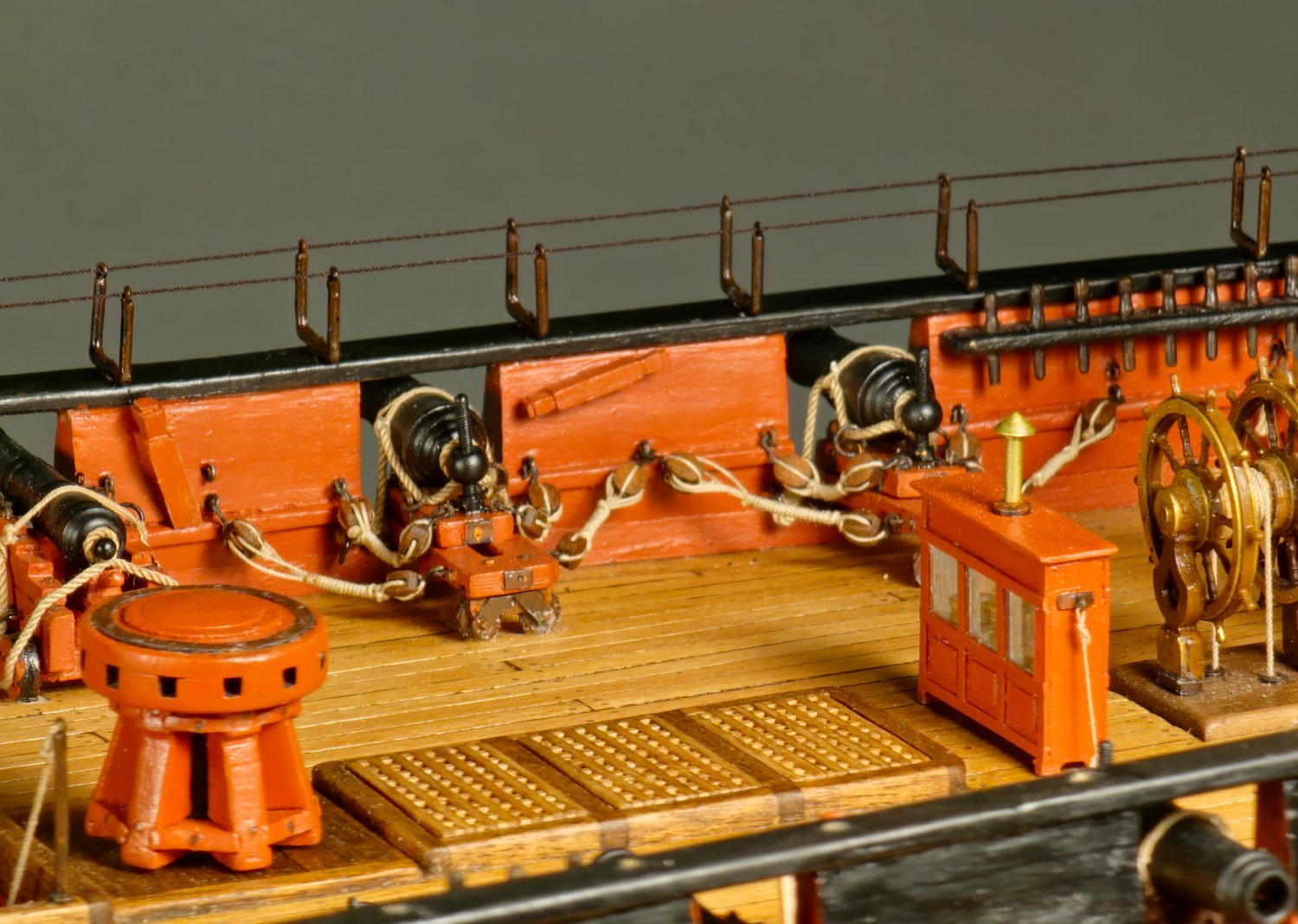
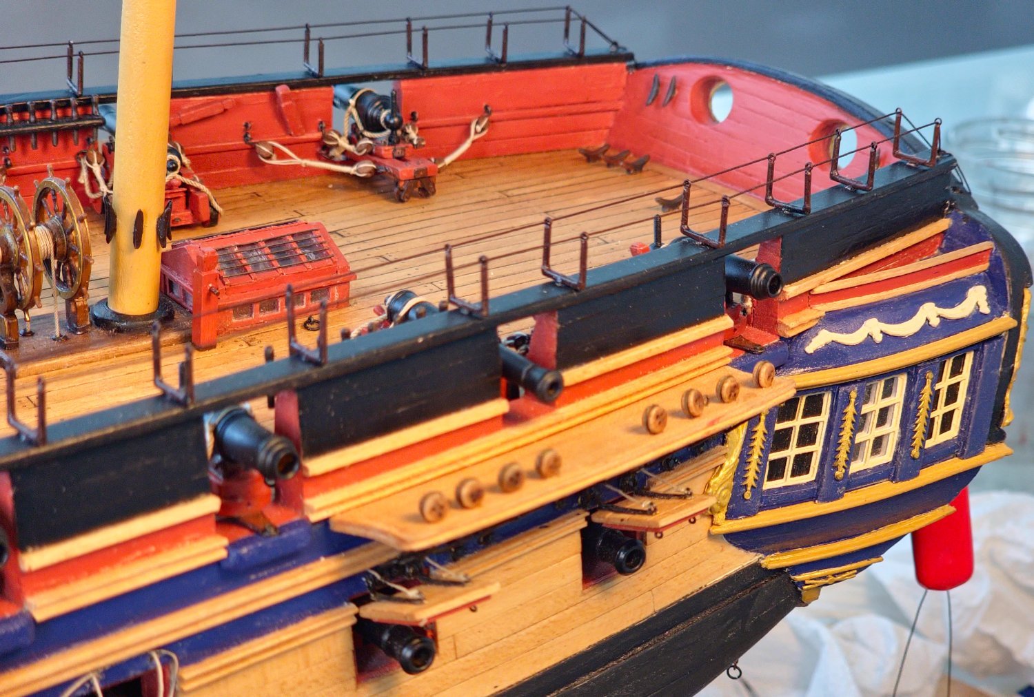
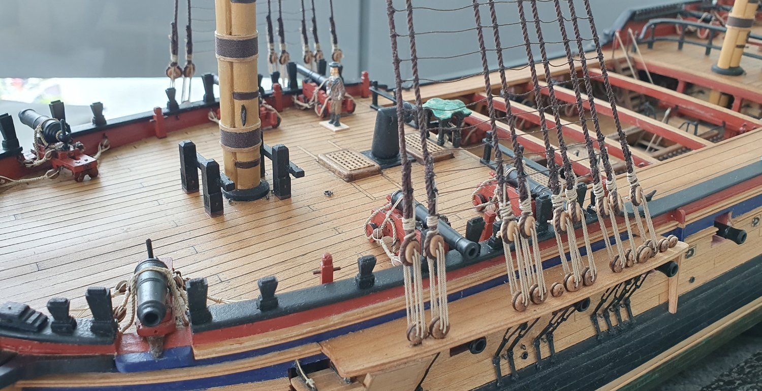
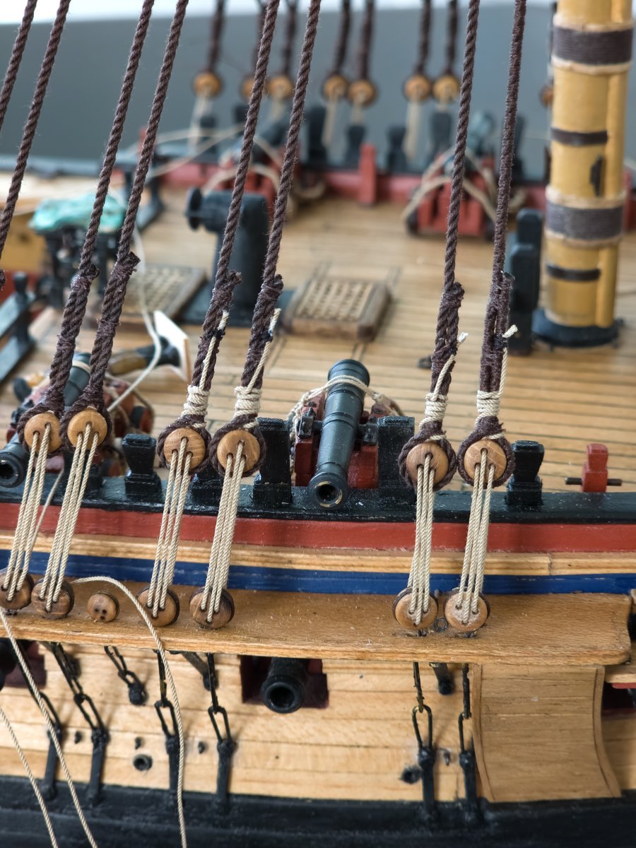
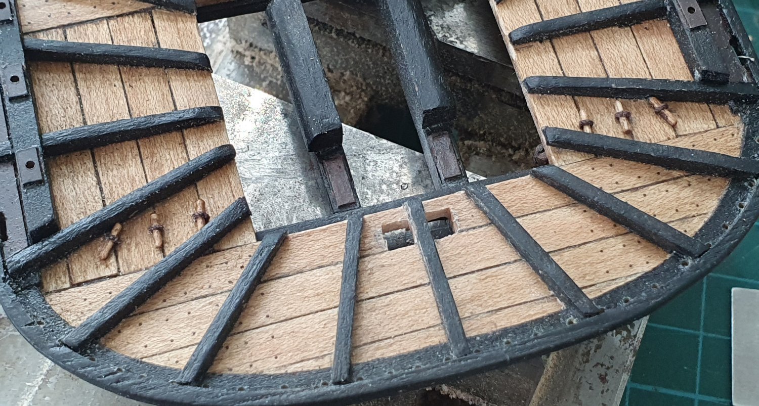
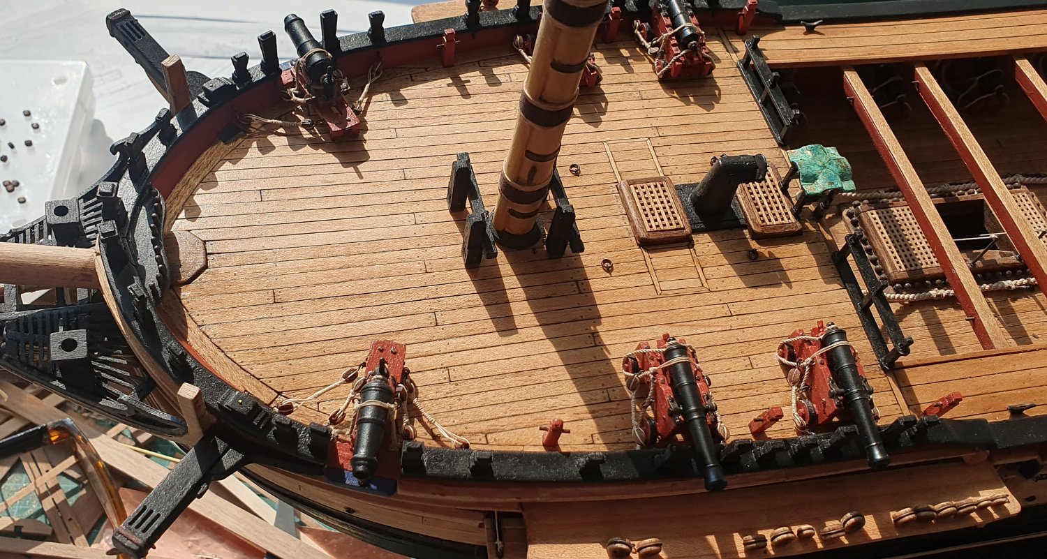
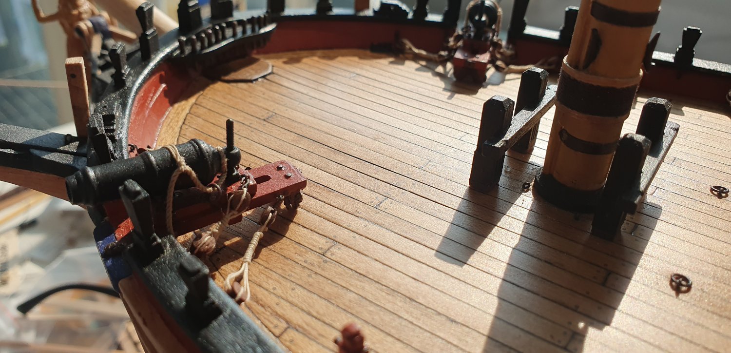
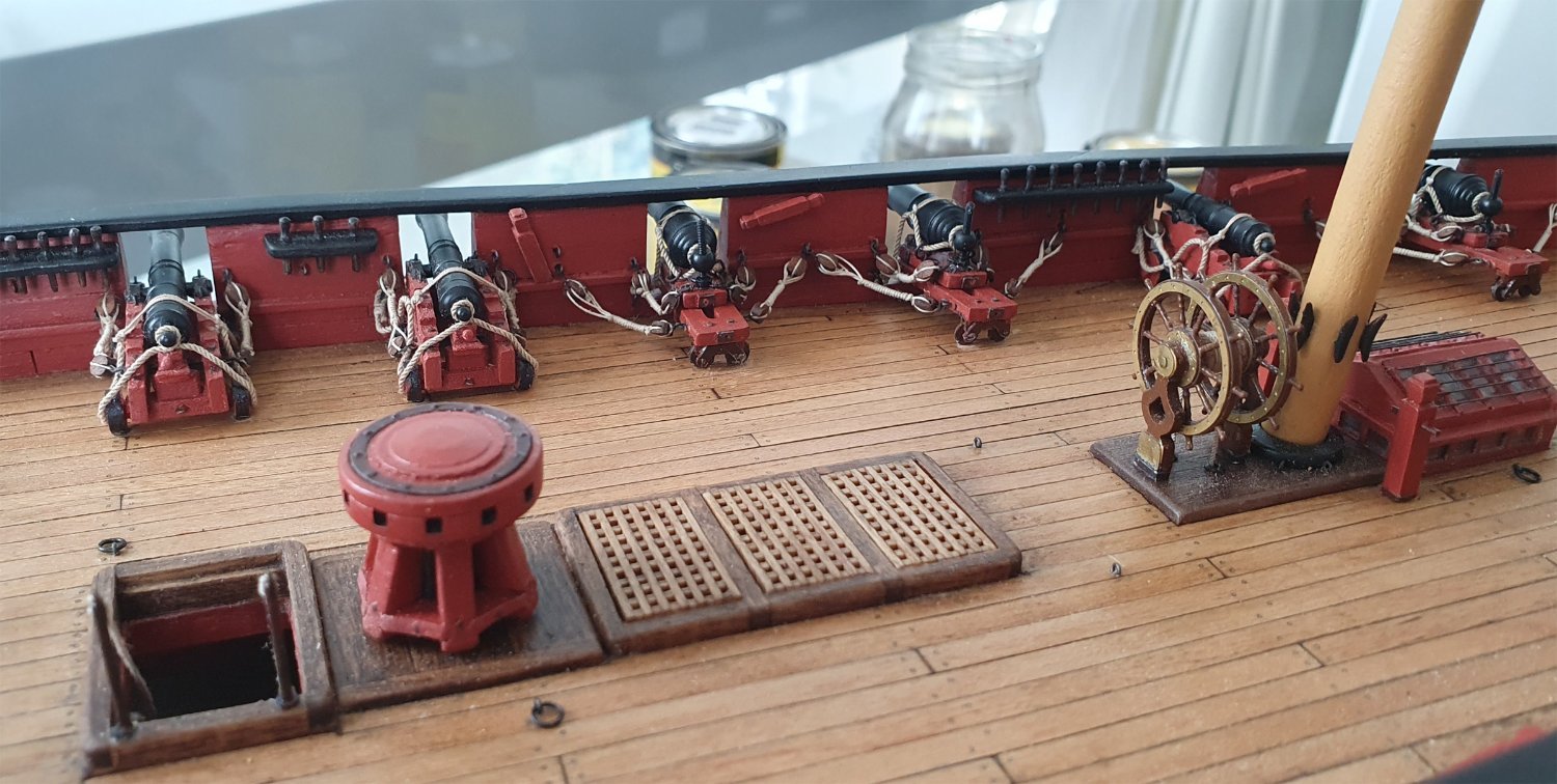
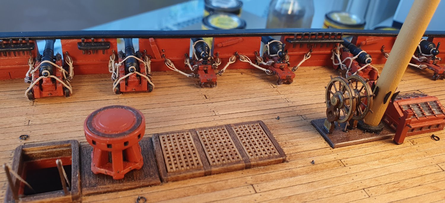
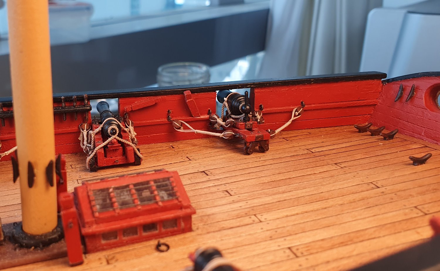
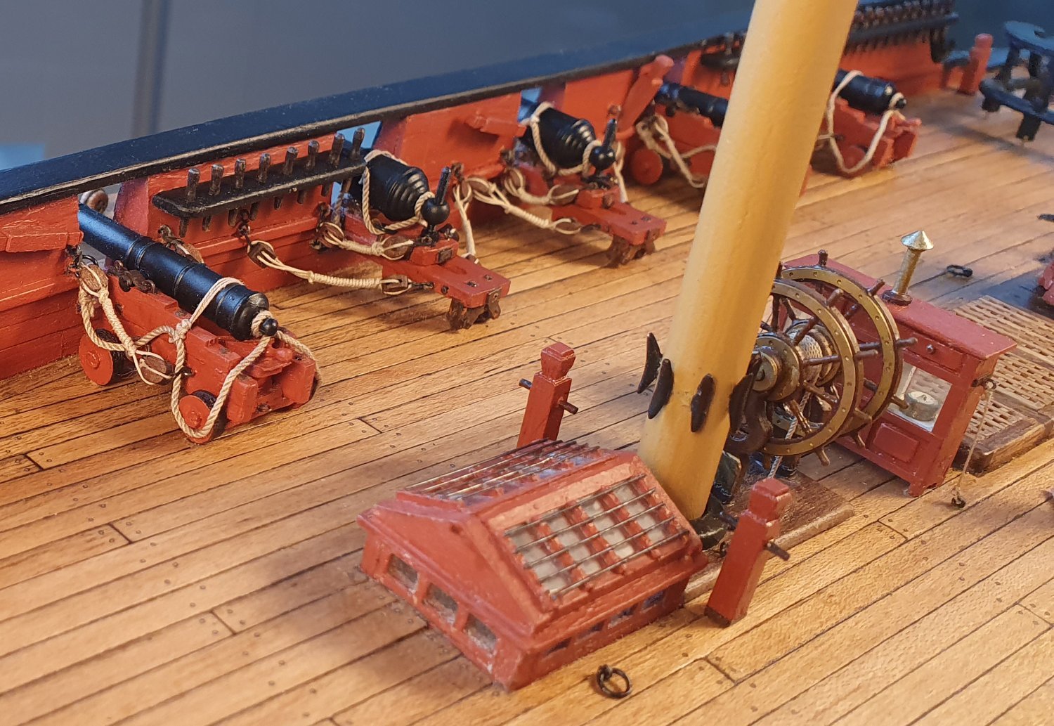
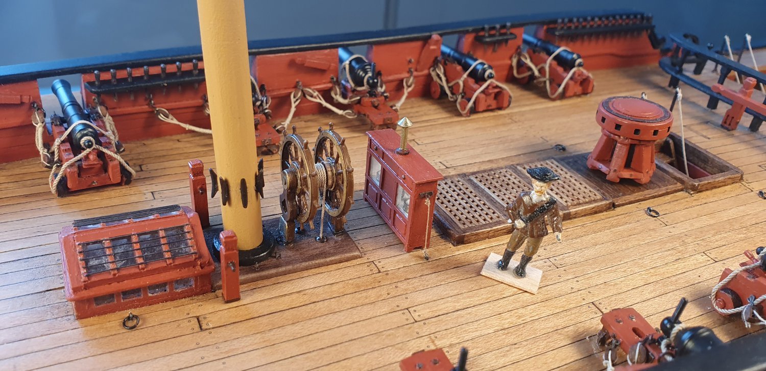
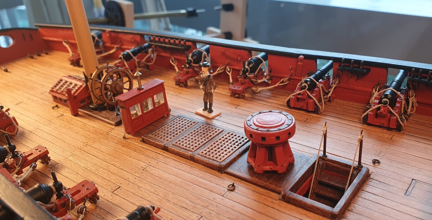
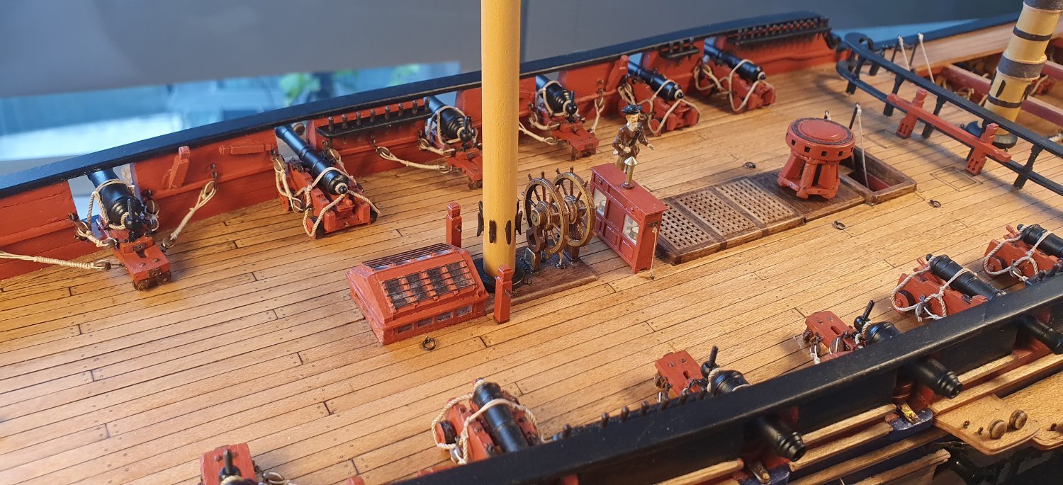
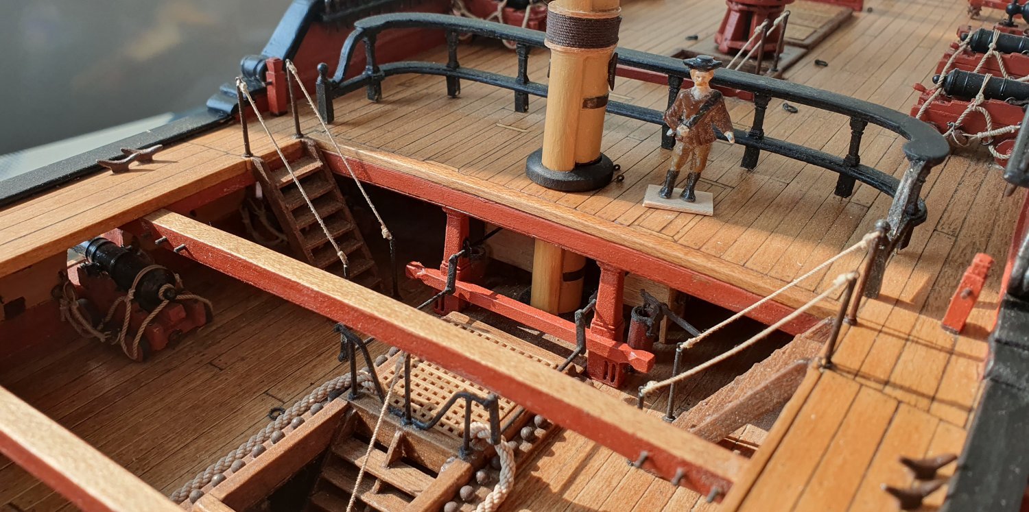
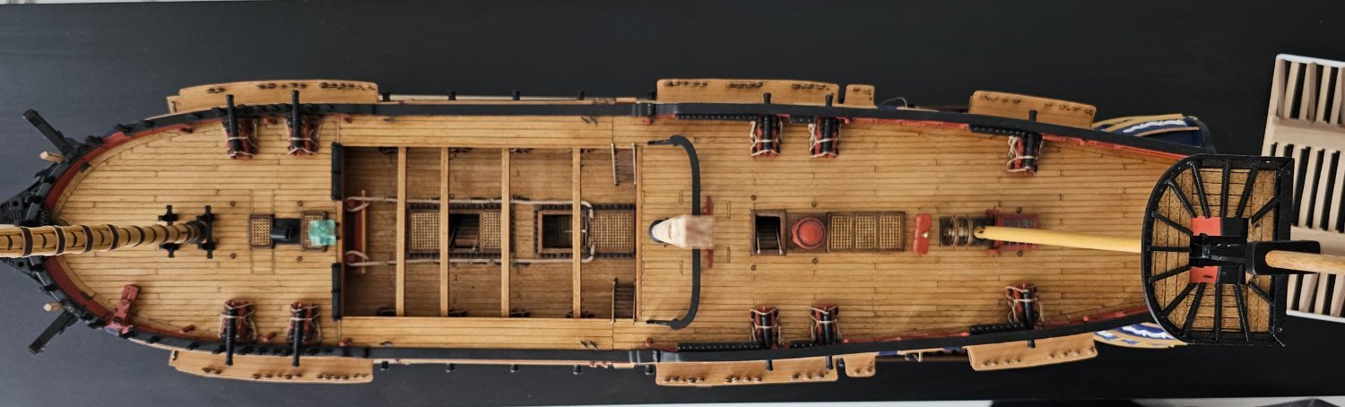
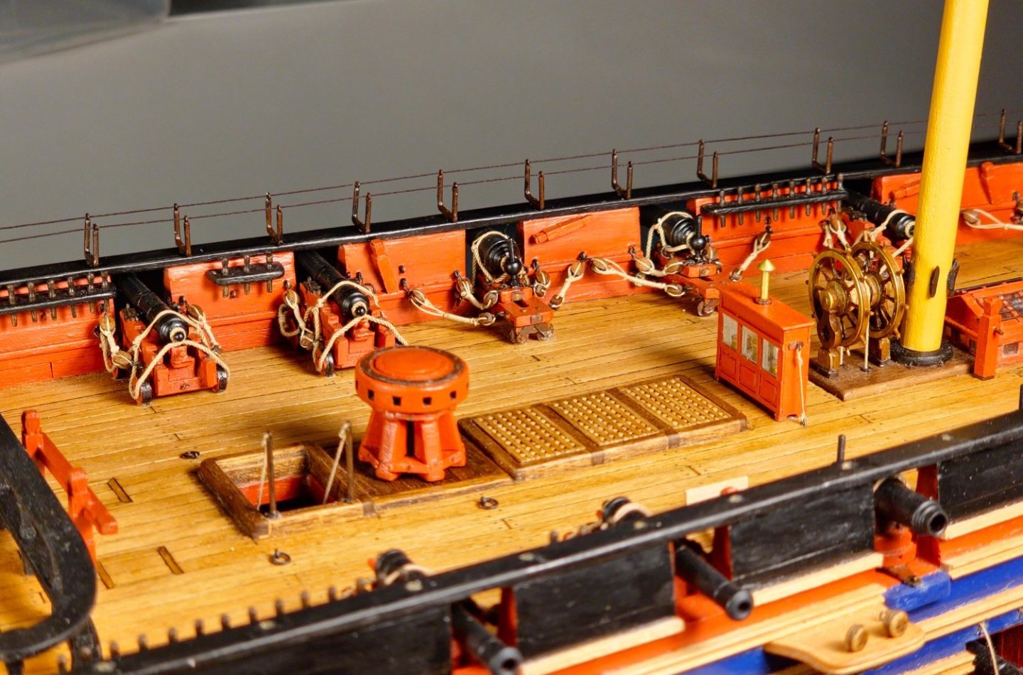
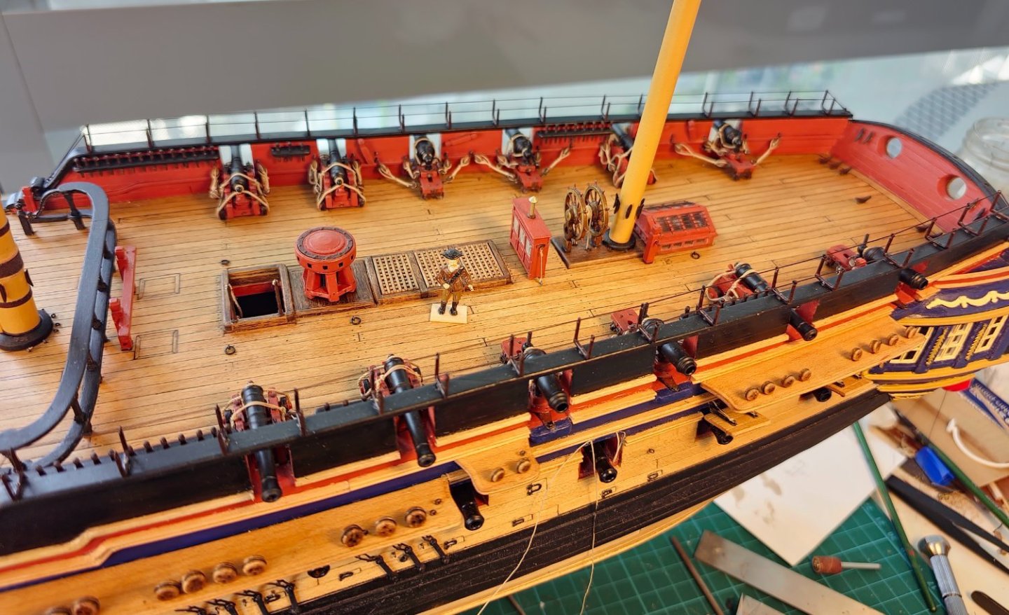
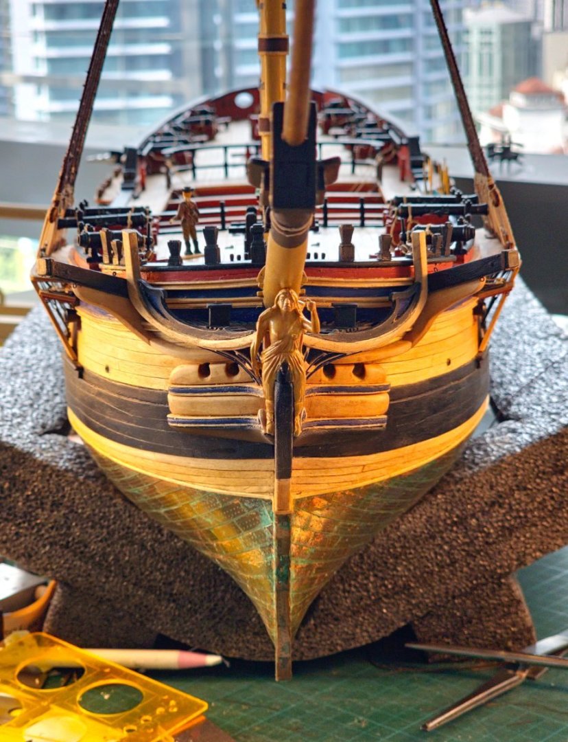
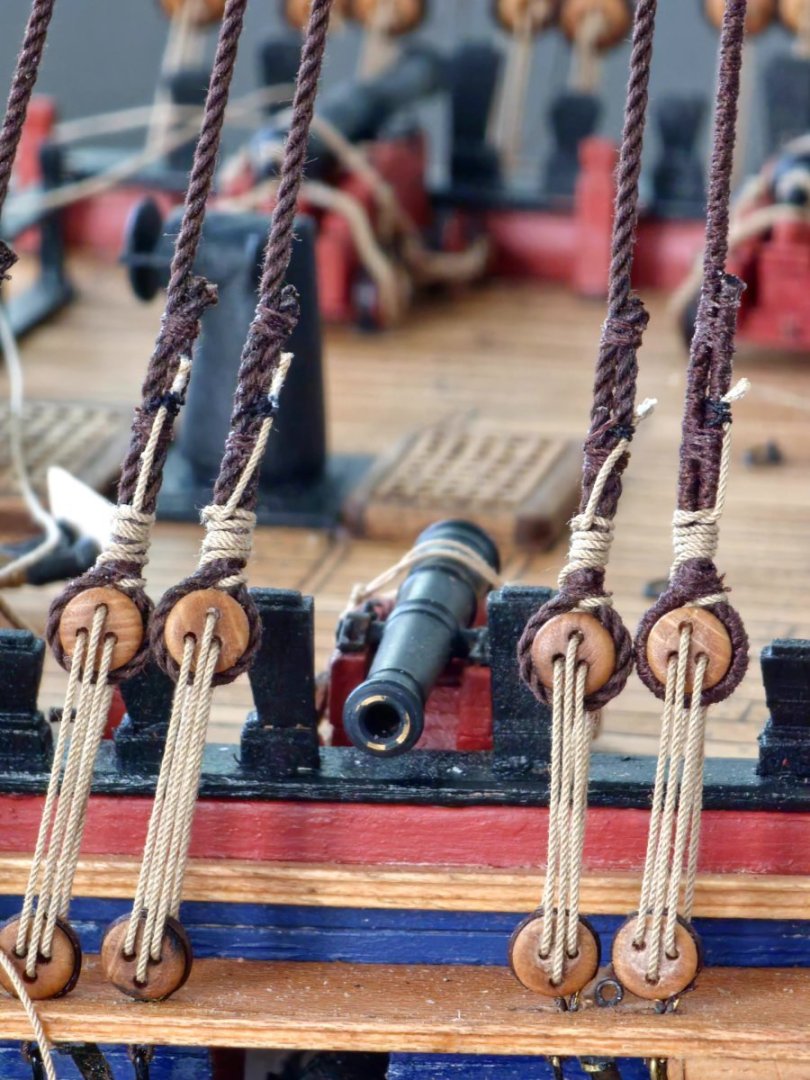
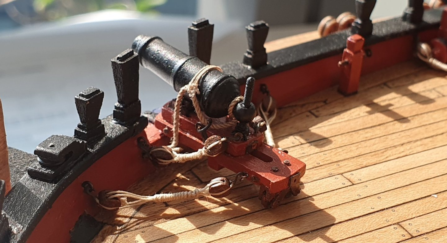
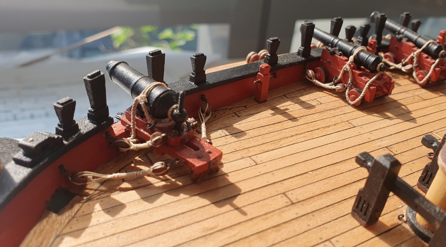
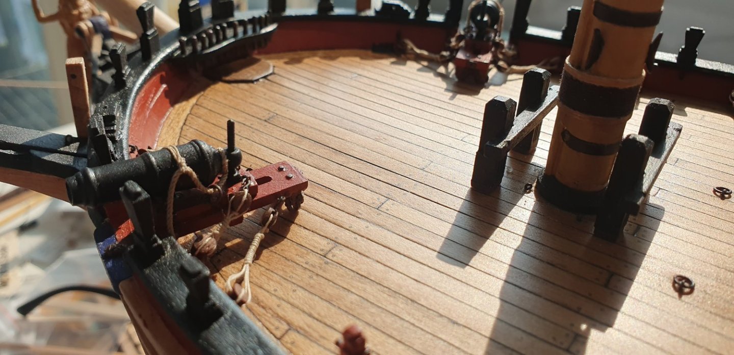
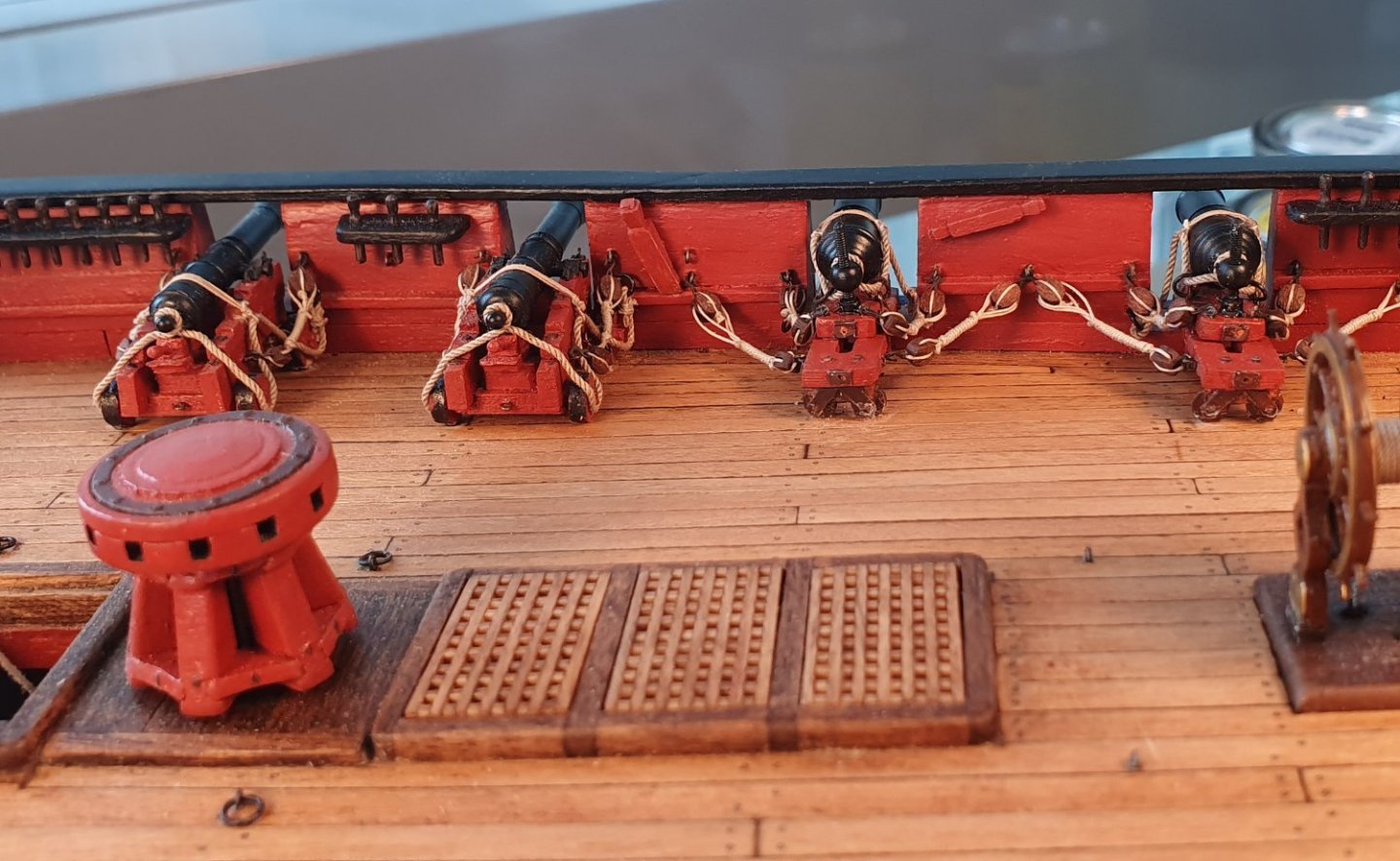
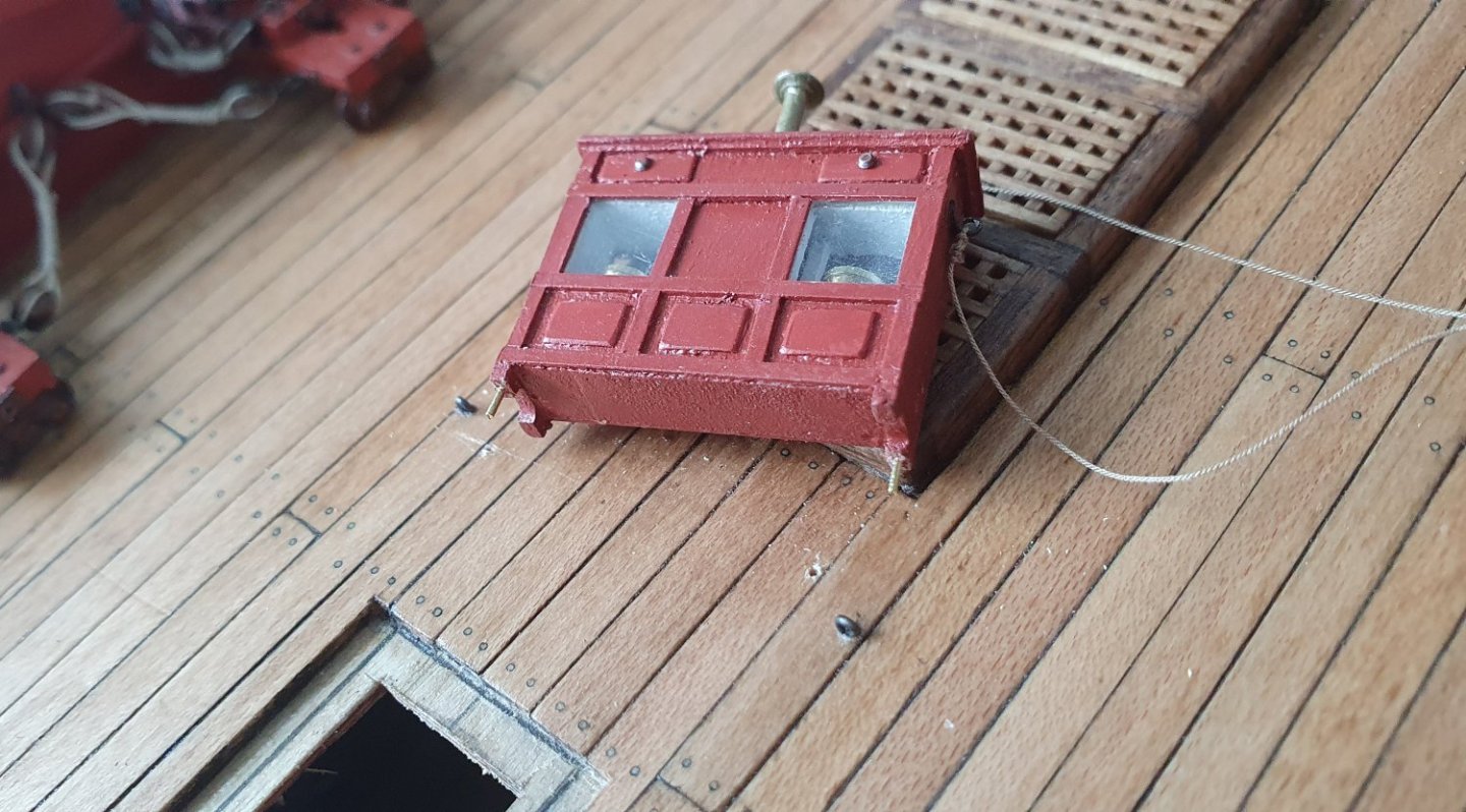
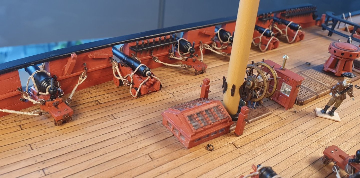
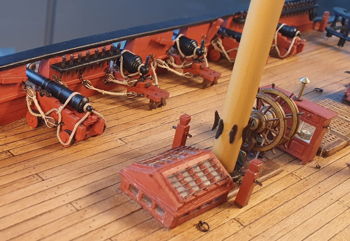
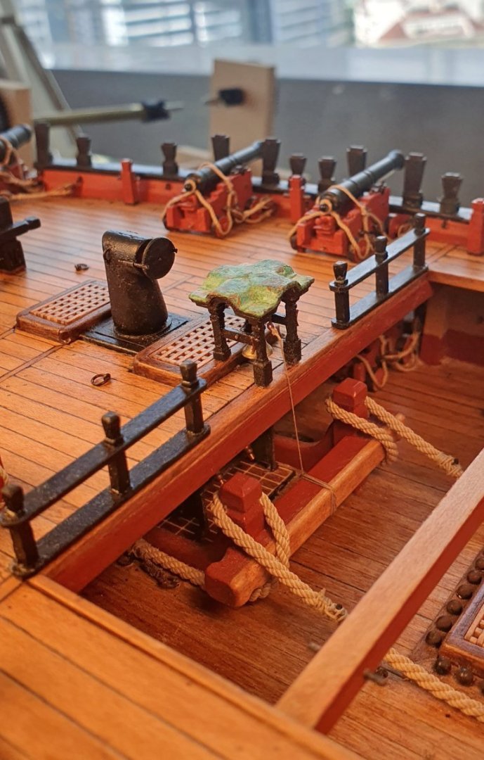
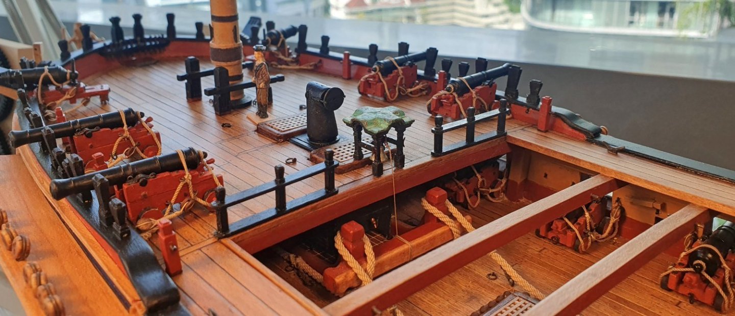
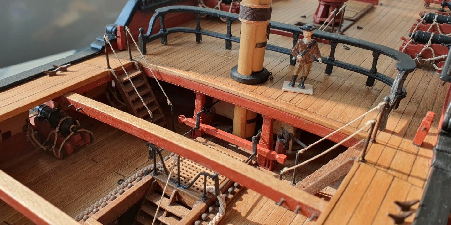
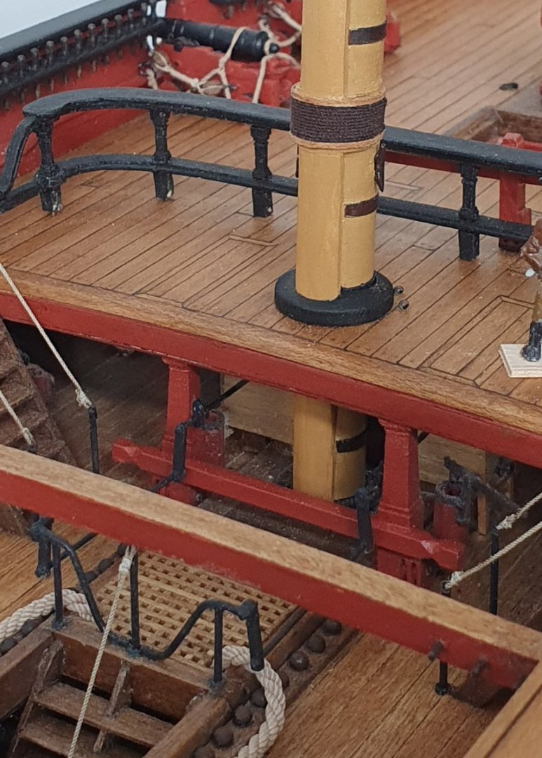
I carried on doing not very much. I think it is an avoidance strategy as the rigging stage is looming large. I went ahead and rigged and installed the carronades. I was quite disappointed with the end result . With the cannons, I had the entire lower deck to practice on before I got to the upper decks but no such luxury with the carronades. On the positive side it does mean that all of the guns are now in position unless I decide to add swivel guns to the tops. With the guns in place and rigged it did allow me to glue down the remaining deck furniture. For the most part I drilled holes into the legs so that I could insert 0.5mm diameter brass rods to act as dowels in the hope that they give some protection against an errant elbow later on in the build. I also took this opportunity to fix the lower masts in place. For these I used the merest dab of glue to position them. I am relying on gravity and rigging to hold these elements. To be fair, once rammed in, they sit quite snugly in their holes.


-
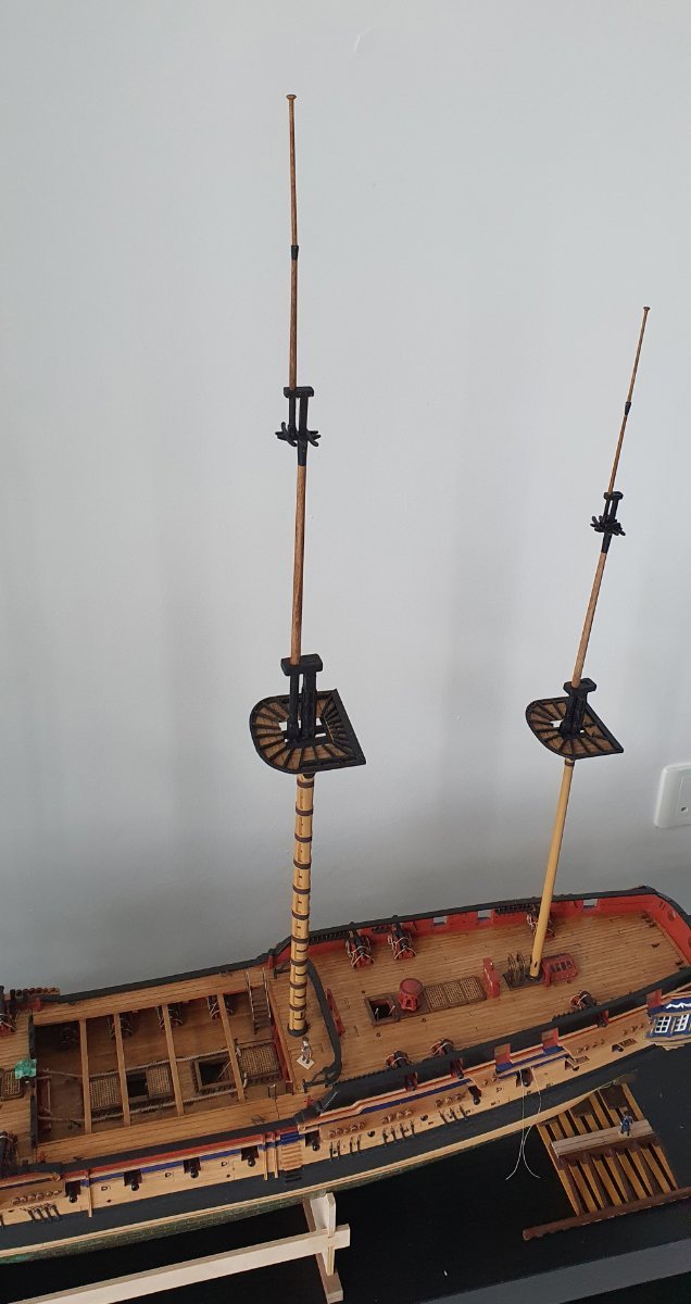
Thanks David. I guess you have had your masts up for a while so you are used to them by now but their height is still quite surprising to me. I am going to have to rethink the final display location as it will not fit on top of the bookcase as I had envisaged. I am currently using the long pole heads but they are built as separate pieces with brass rod dowels so I can swap them out for the shorter ones at a later date. Regards, David
-
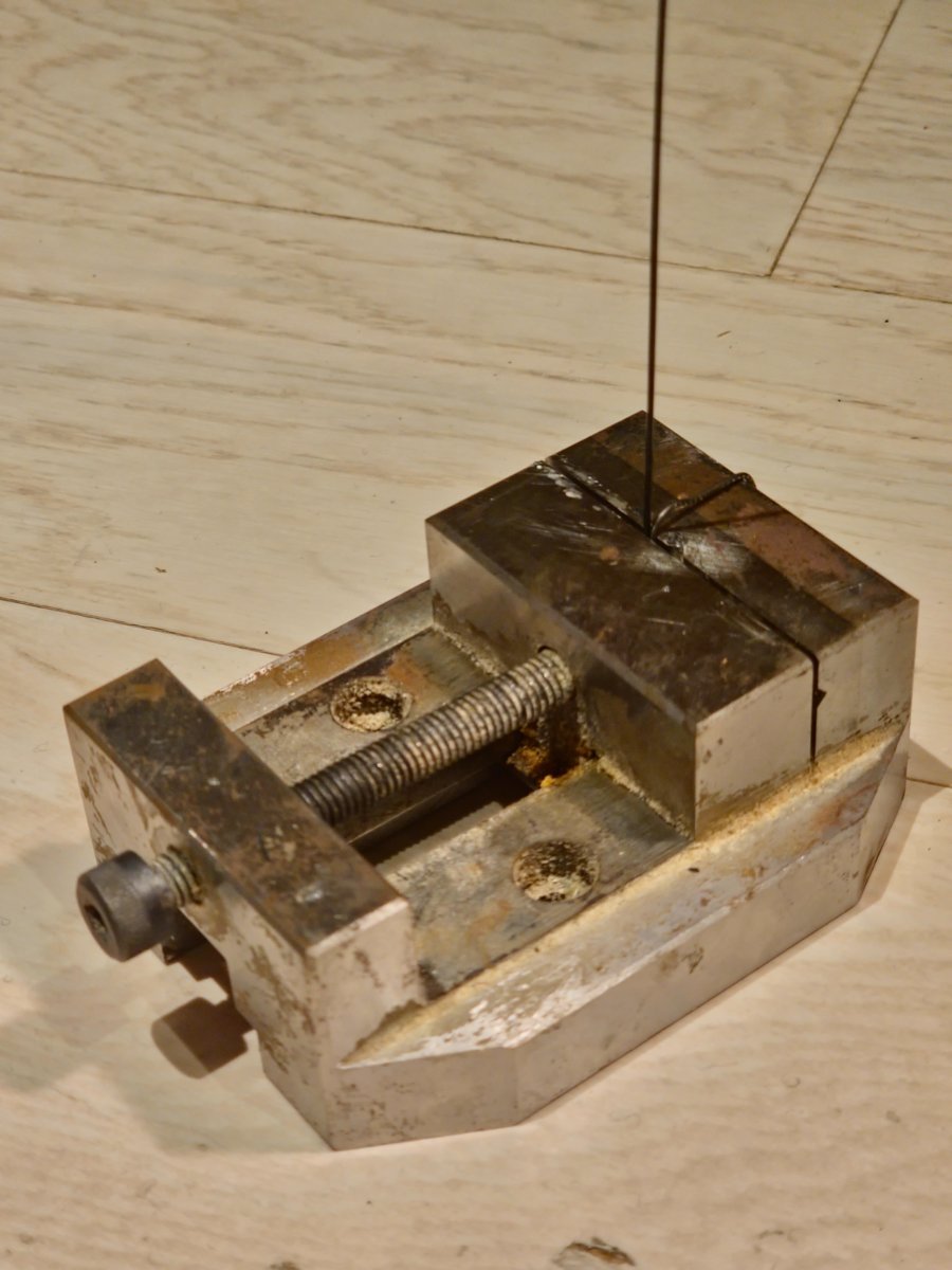
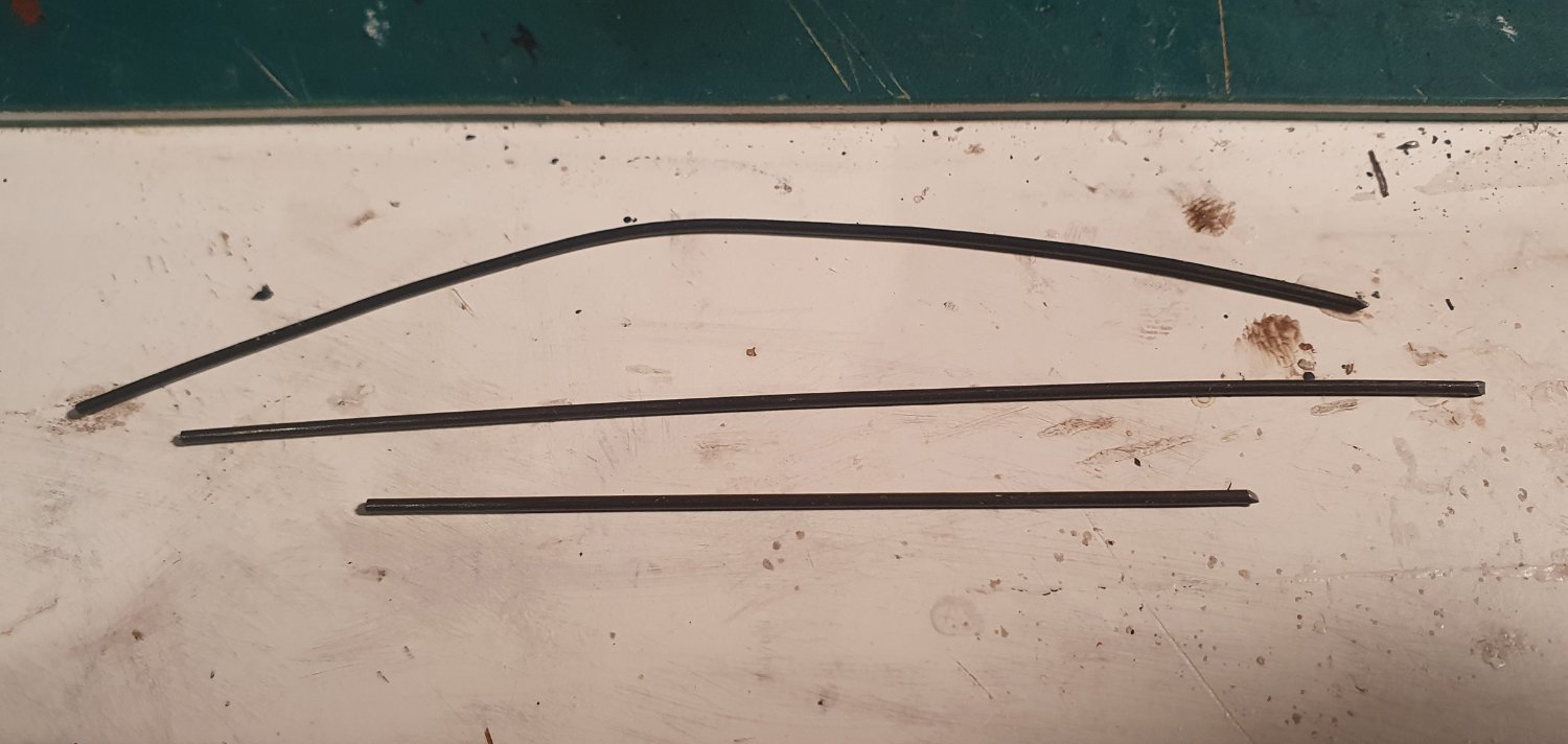
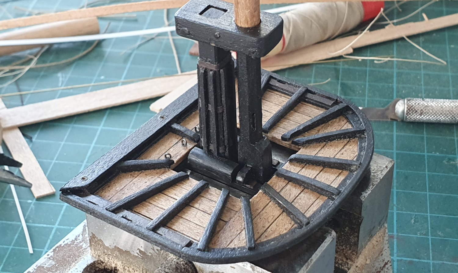
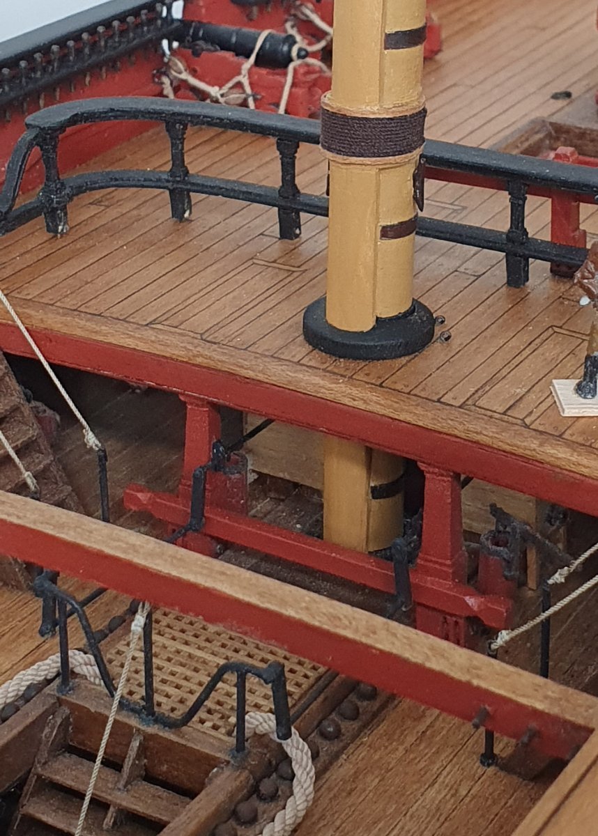
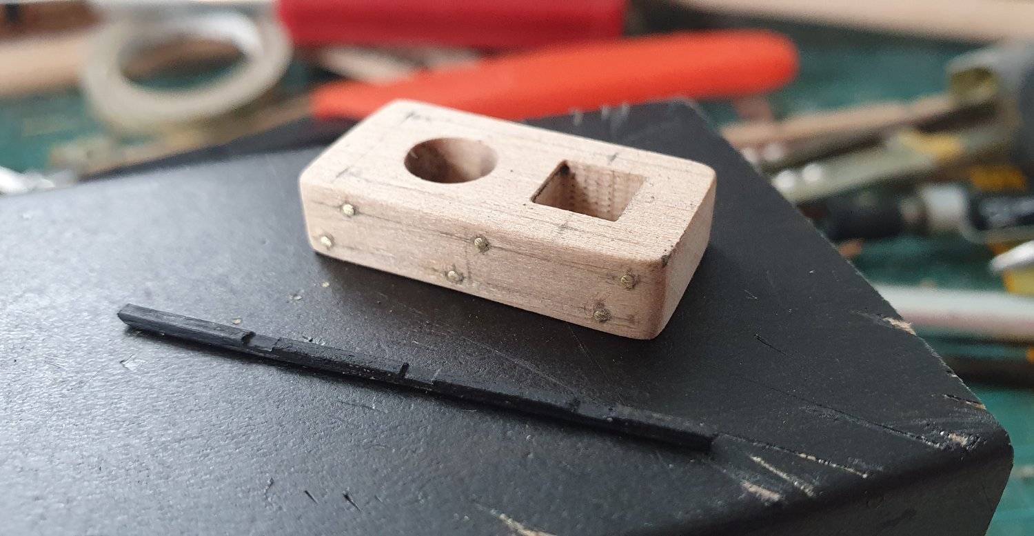
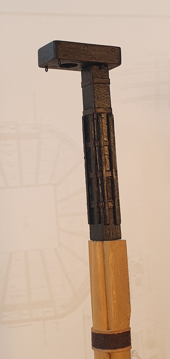
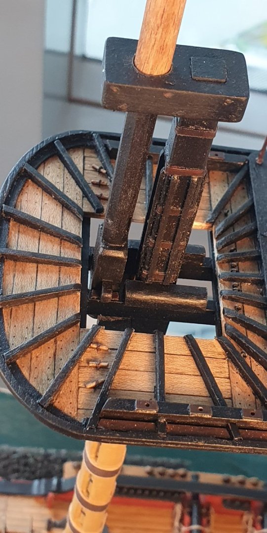
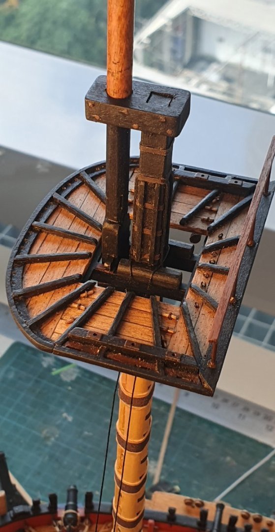
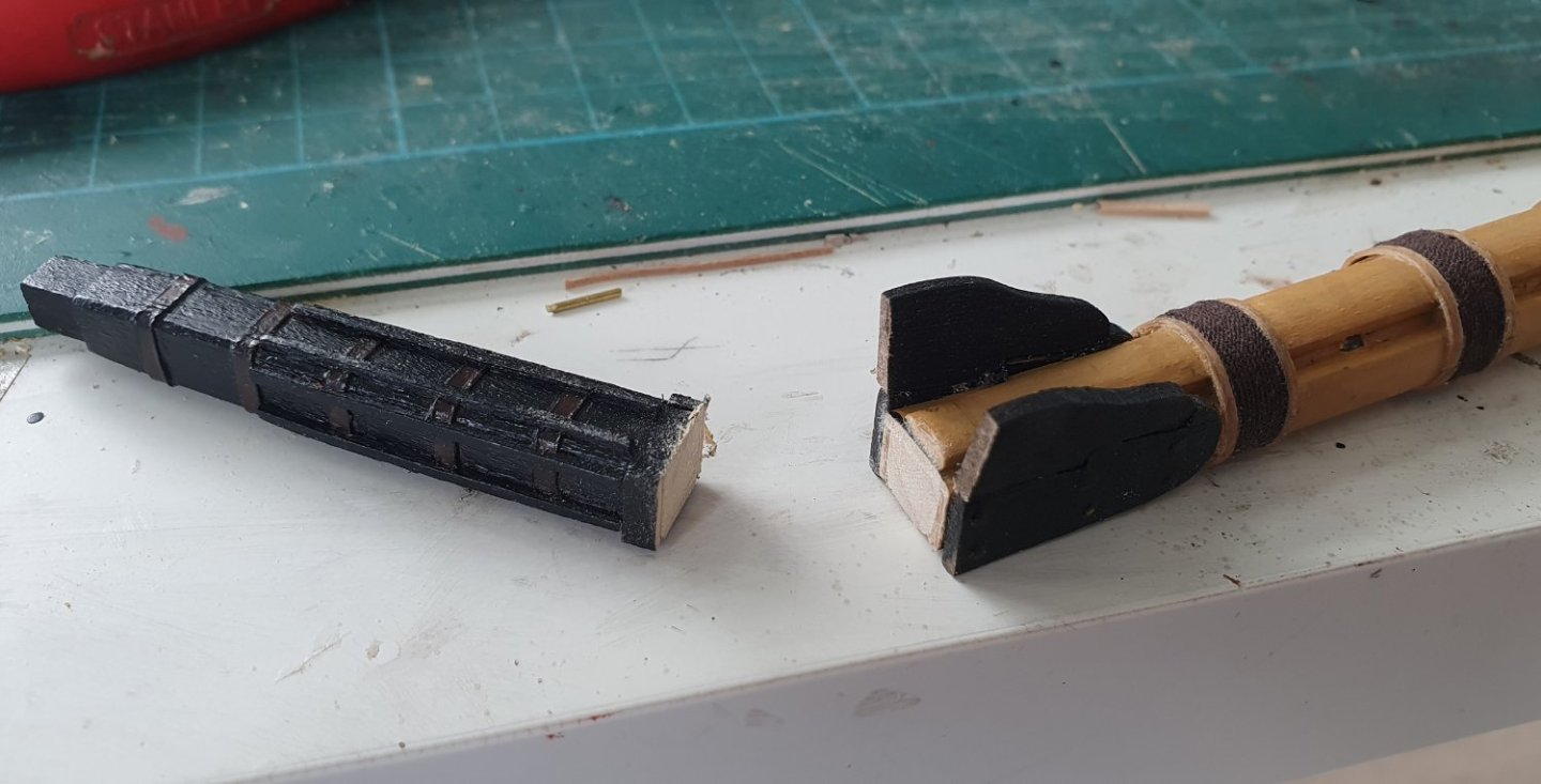
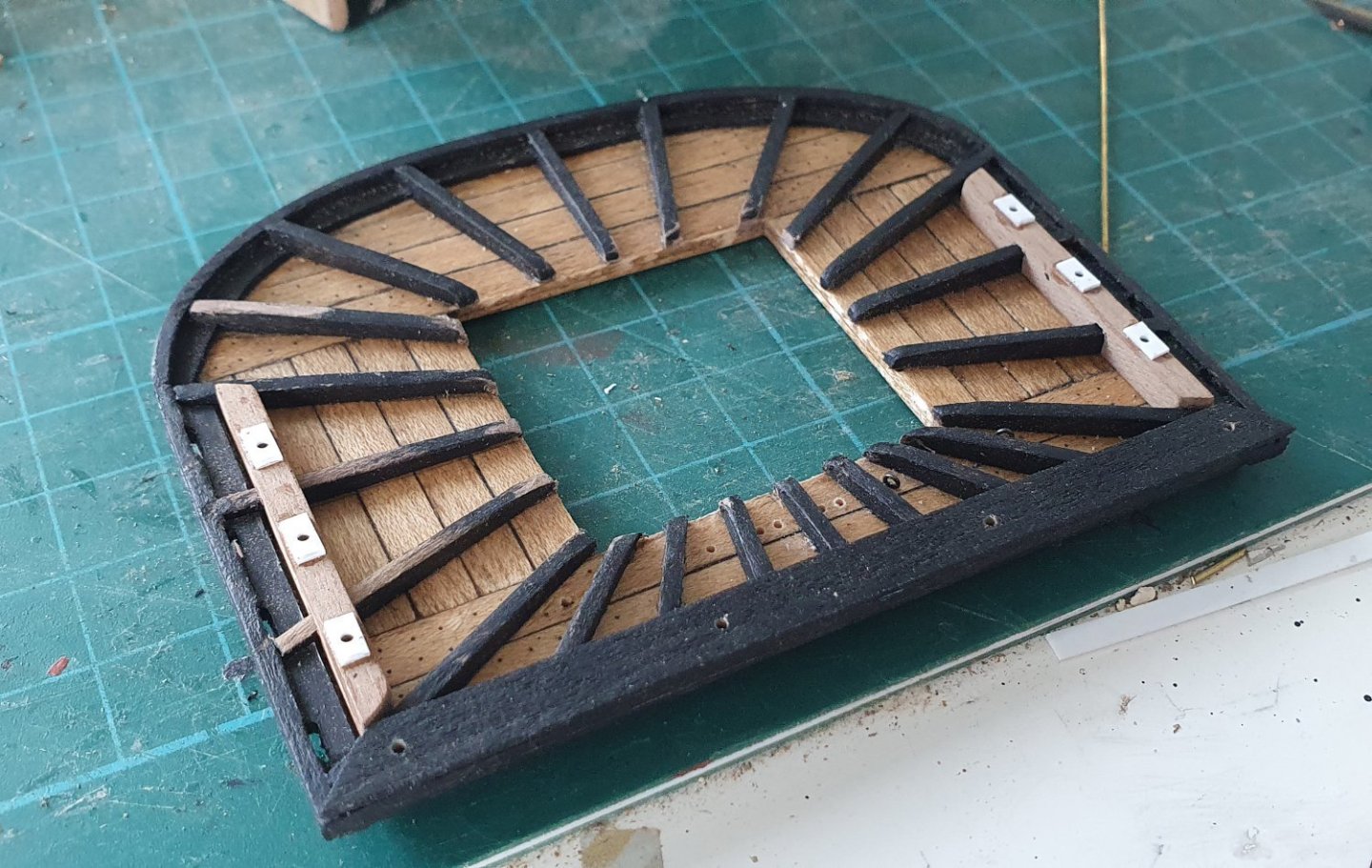
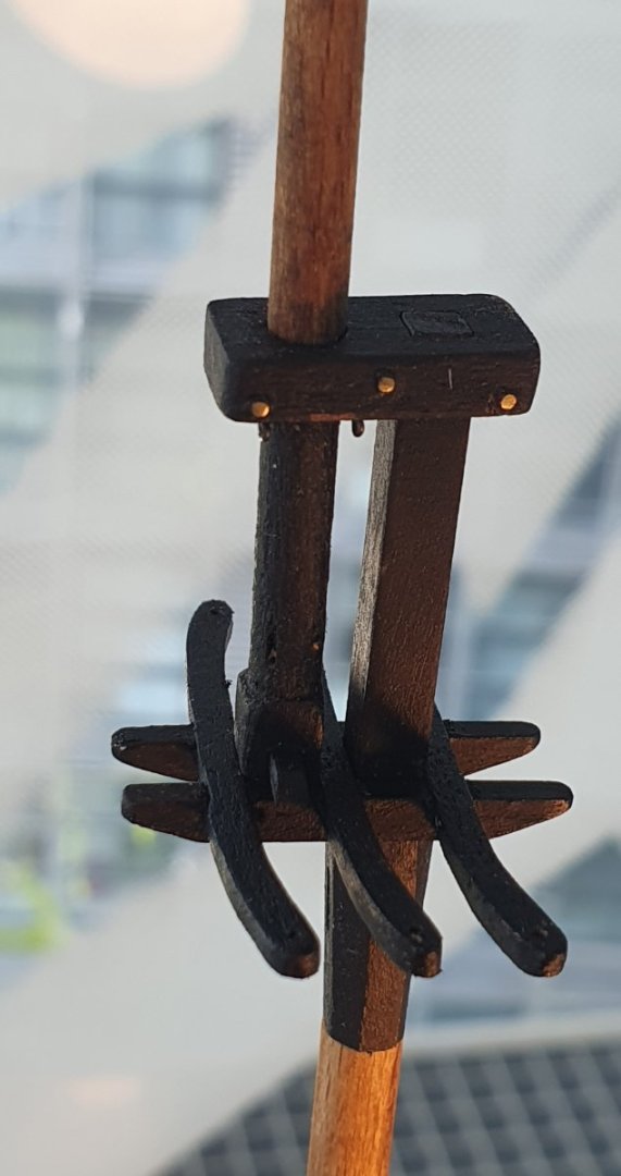
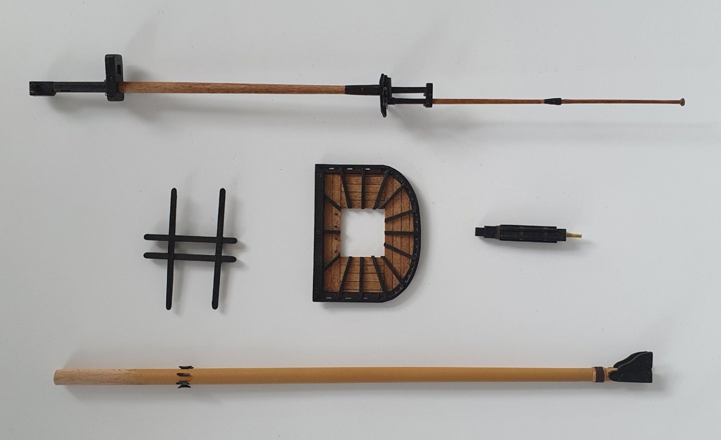
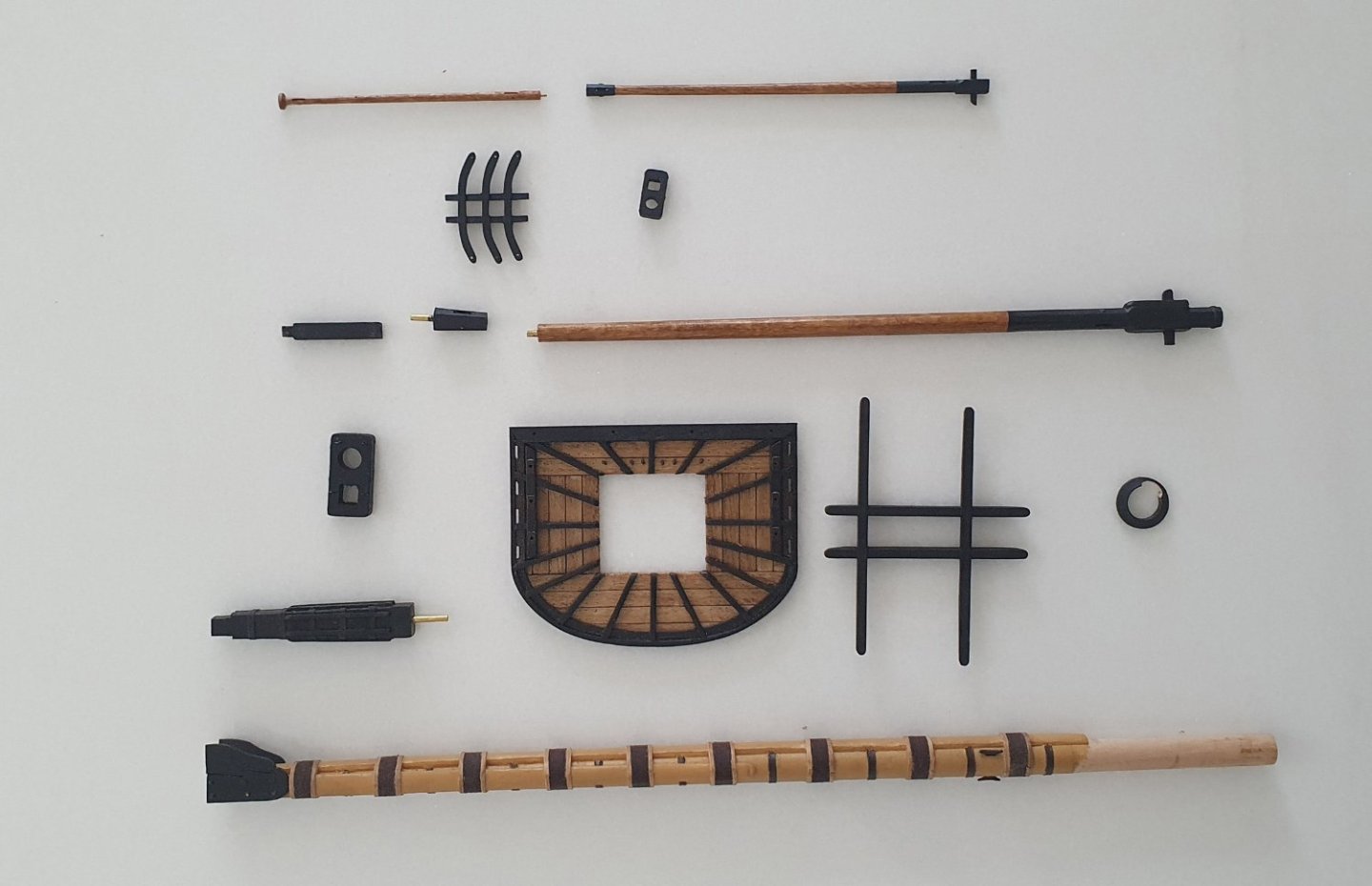
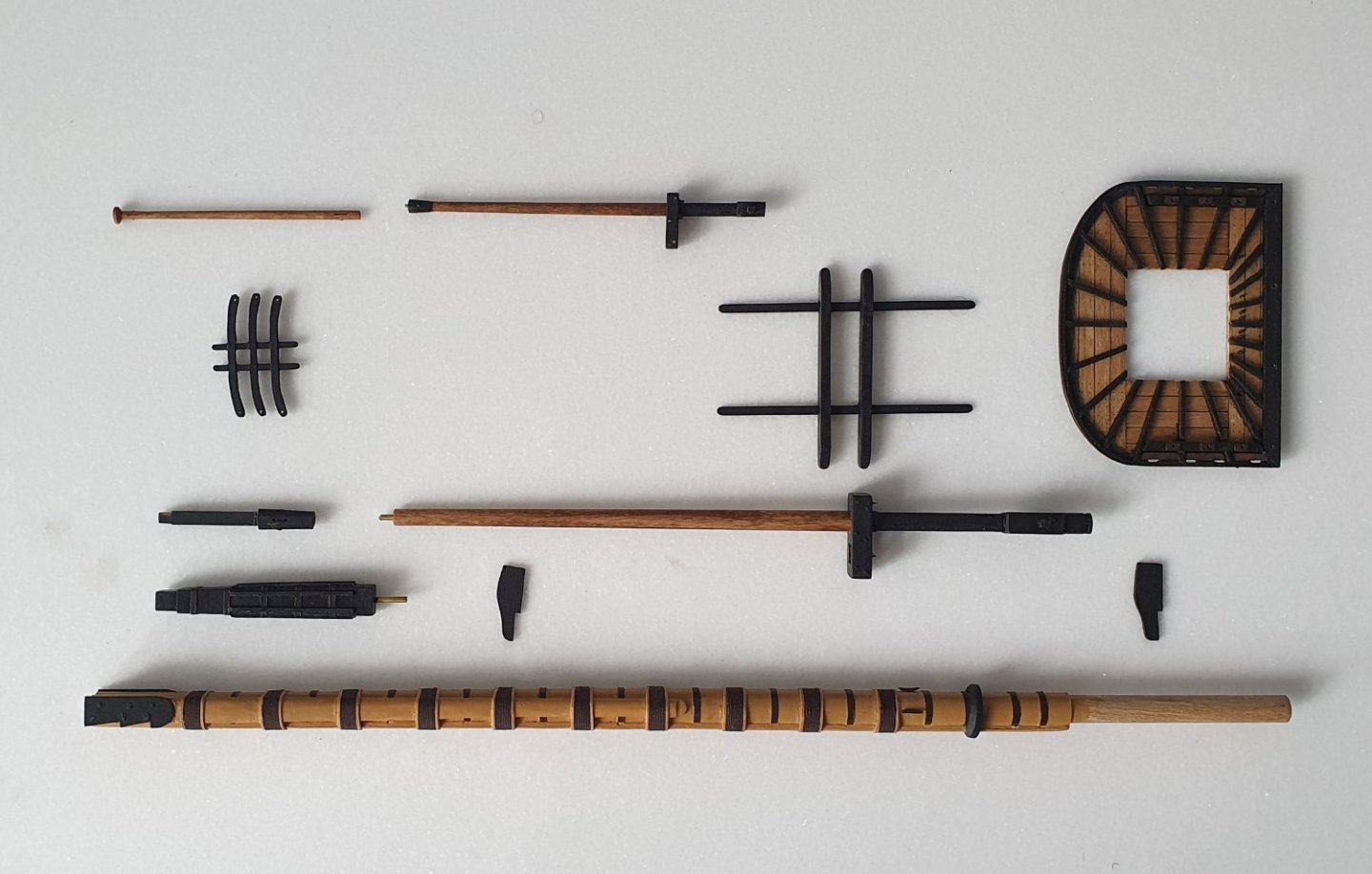
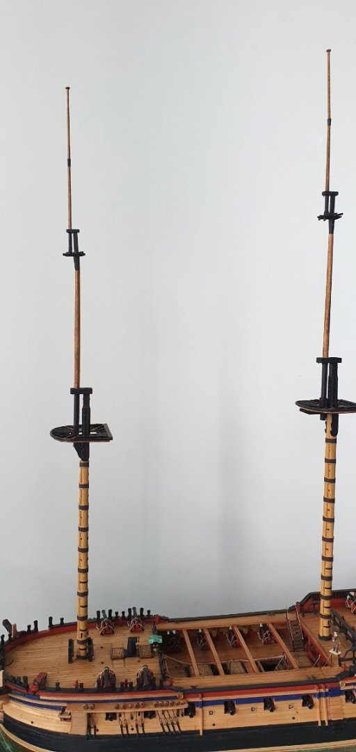
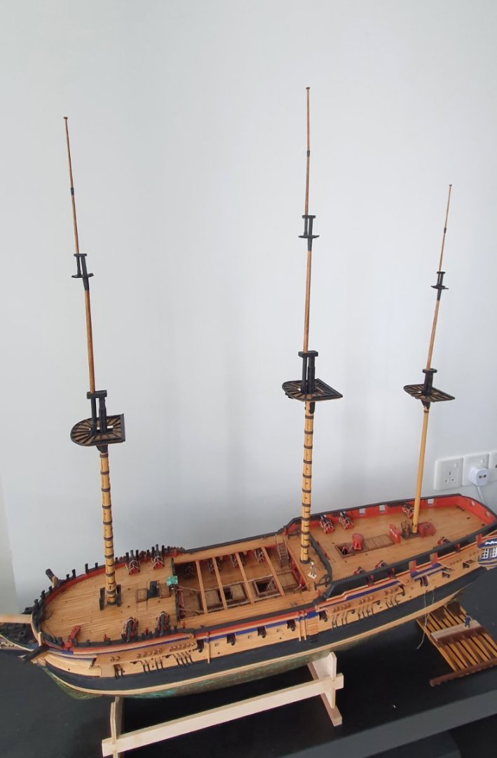
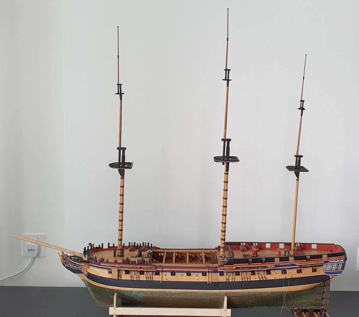
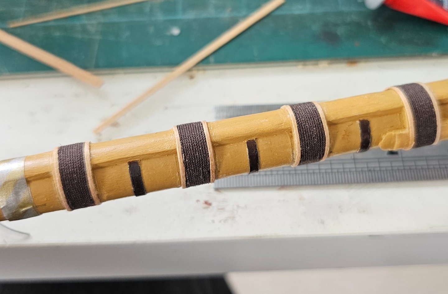
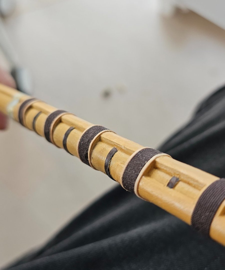
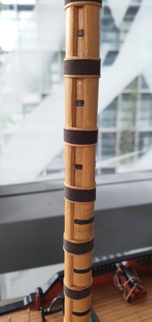
I continued wading through the myriad of pieces that make up the masts. I ran the lower foremast through the table saw and replaced the top with something that was more in keeping with the proportions. I had to remake the cap for a second time as the new top did not fit and I had placed the eyebolts slightly off in the previous one. I then had to give the lower mizzen mast the same treatment. I was somewhat disappointed to find out that, according to Lees, the top of the lower mizzen also has battens. These are quite fiddly to make as you have to notch the rear so that they sit flush over the metal bands. I then turned my attention to completing the elements that comprise the main mast. I had already finished the lower main but needed to make a new collar for the junction at the base to account for the increased diameter. This also had to be larger so that I could cut out a notch to accept the front fish. I had to start with a 20mm diameter beech dowel which was too large for the lathe so I had to resort to the milling machine and some freehand dremeling. As the hole in the middle had to be large enough to pass over the lower metal bands there was an unsightly gap between the collar and the mast once I got it into its final position. I fudged this by introducing another band at the deck level that should fill the gap and not be too noticeable when painted black. I completed the tops to match the other two and made up the lower crosstrees. for these I used the kit supplied cross trees but remade the trestle tees. The bibs and cheeks at the hounds were remade as 2 separate pieces as per the Steel drawings with the bibs splayed. I also added the faux bolts to attach the cheeks to the mast. I then moved onto the main topmast. The tables in Steel note that this is the same diameter as the fore topmast but the AOTSD indicate that it is slightly larger in diameter. I went with the AOTSD dimensions as they are the ones that I had decided to follow but at this point I can no longer remember if I had not got confused and mixed and matched at some point. At 1:64 scale though the tolerances inherent in my shoddy workmanship should render that concern moot. The below photos show the parts of the three masts broken down. Sadly, these are not complete yet as I still must add rigging blocks and other sundry items., It does however indicate that I am coming to the end of the fabrication stage of the model. I only have the yards and the bowsprit left and then it is all rigging. I just realised that I also have the hammock cranes, netting, anchors, and the ships boats to complete. Seems like I am nowhere near the end of the fabrication stage. Of course, I am forgetting the giant base but it is still 50/50 as to that happening. I mocked-up the masts in-situ with all the elements balanced somewhat precariously to give myself an idea of the final size of the model and I was quite surprised at how tall it is. I hope that I have not bungled the mast dimensions. I suspect the lack of rigging and yards is exaggerating the slenderness ratio making them appear taller. I also opted to use the long pole head which adds to the height. There is always the option of switching these out at a later date if I feel like it.


-
Thanks for the kind words Jason. I was drooling over your recent post showing your headworks progress. It made me want to rip mine out and start again but I have given myself the somewhat arbitrary deadline of the end of the year to finish my model so I cannot afford to be taking too many steps backwards. Regards, David
-
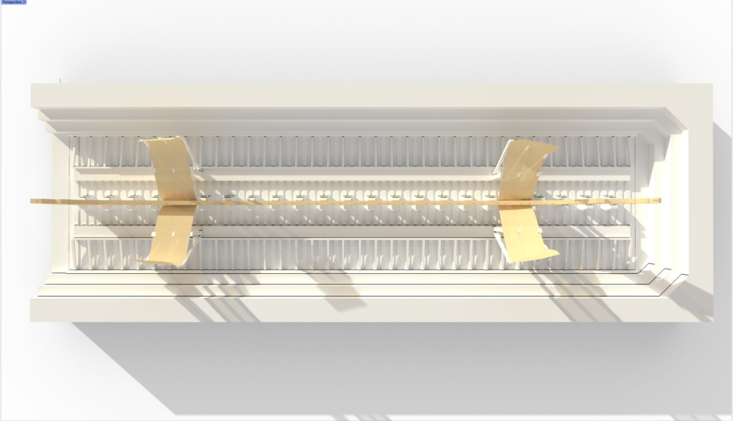
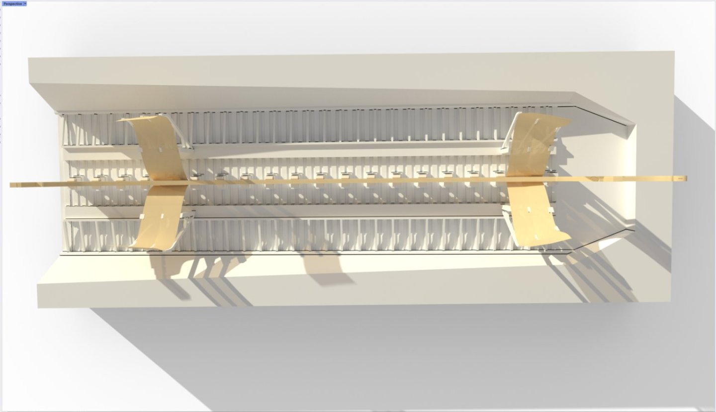
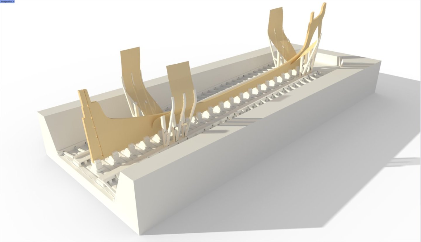
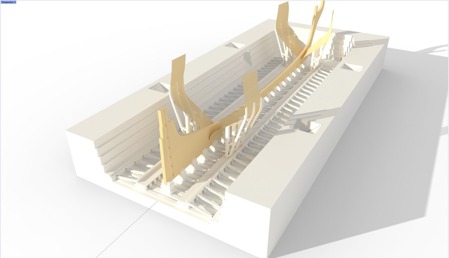
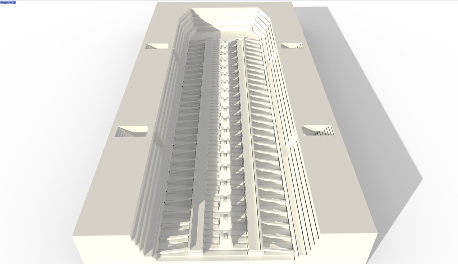
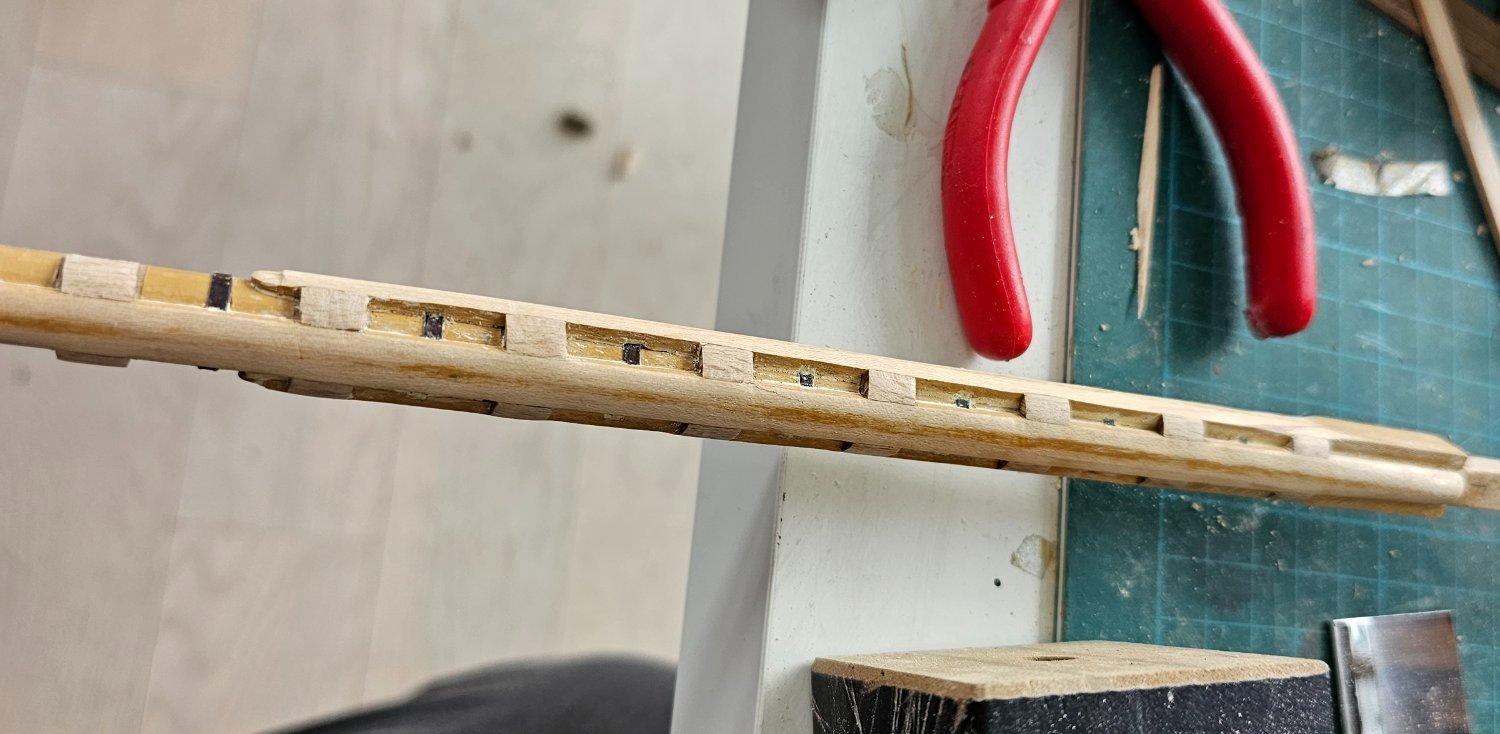
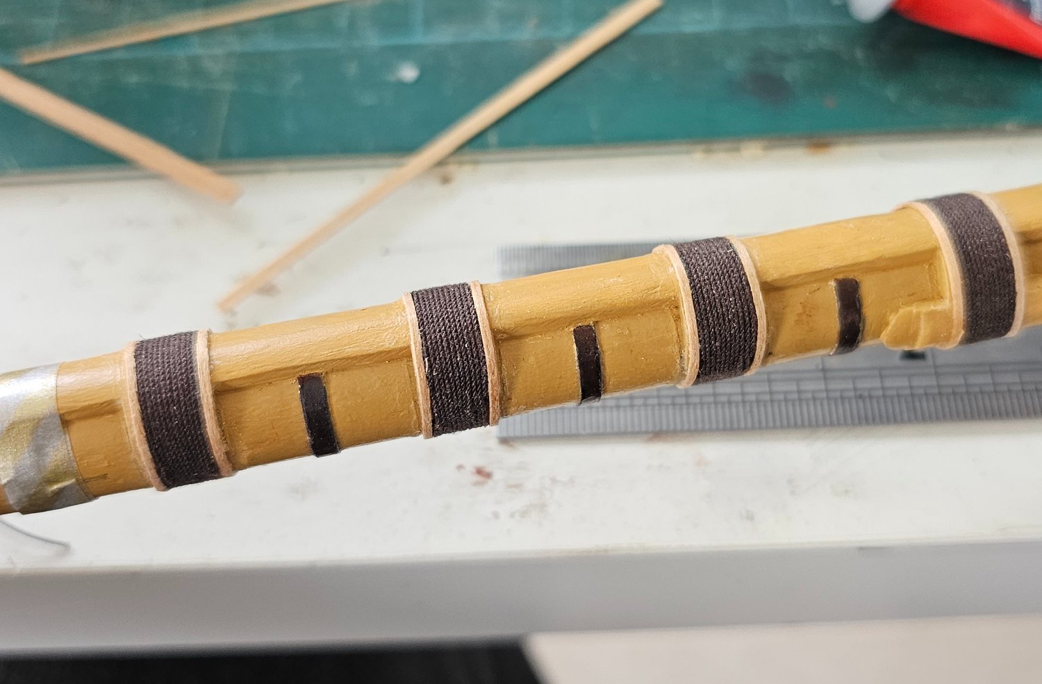
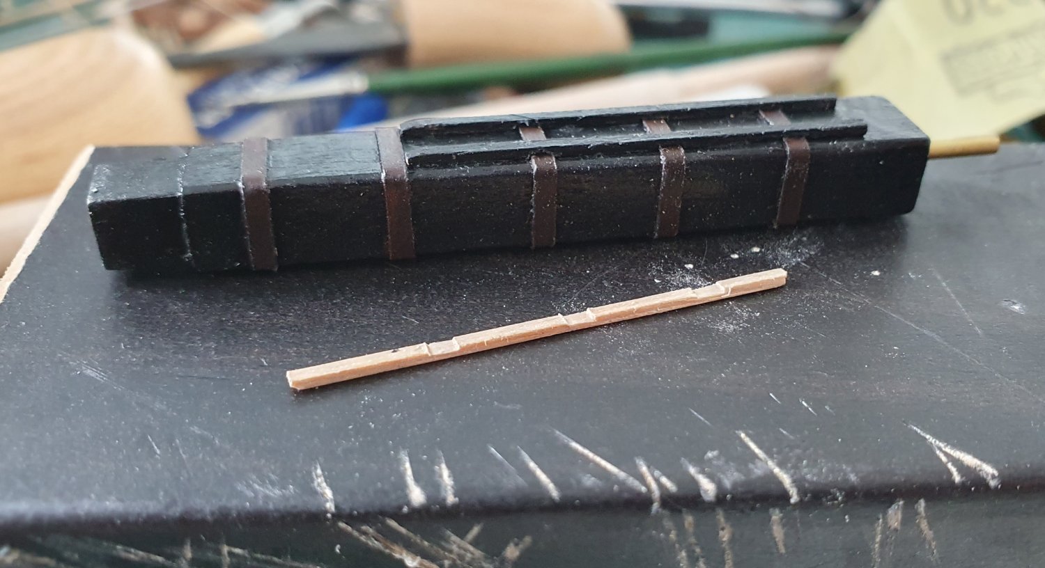
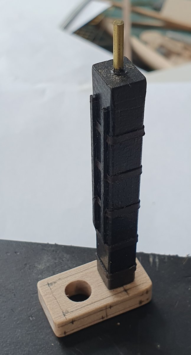
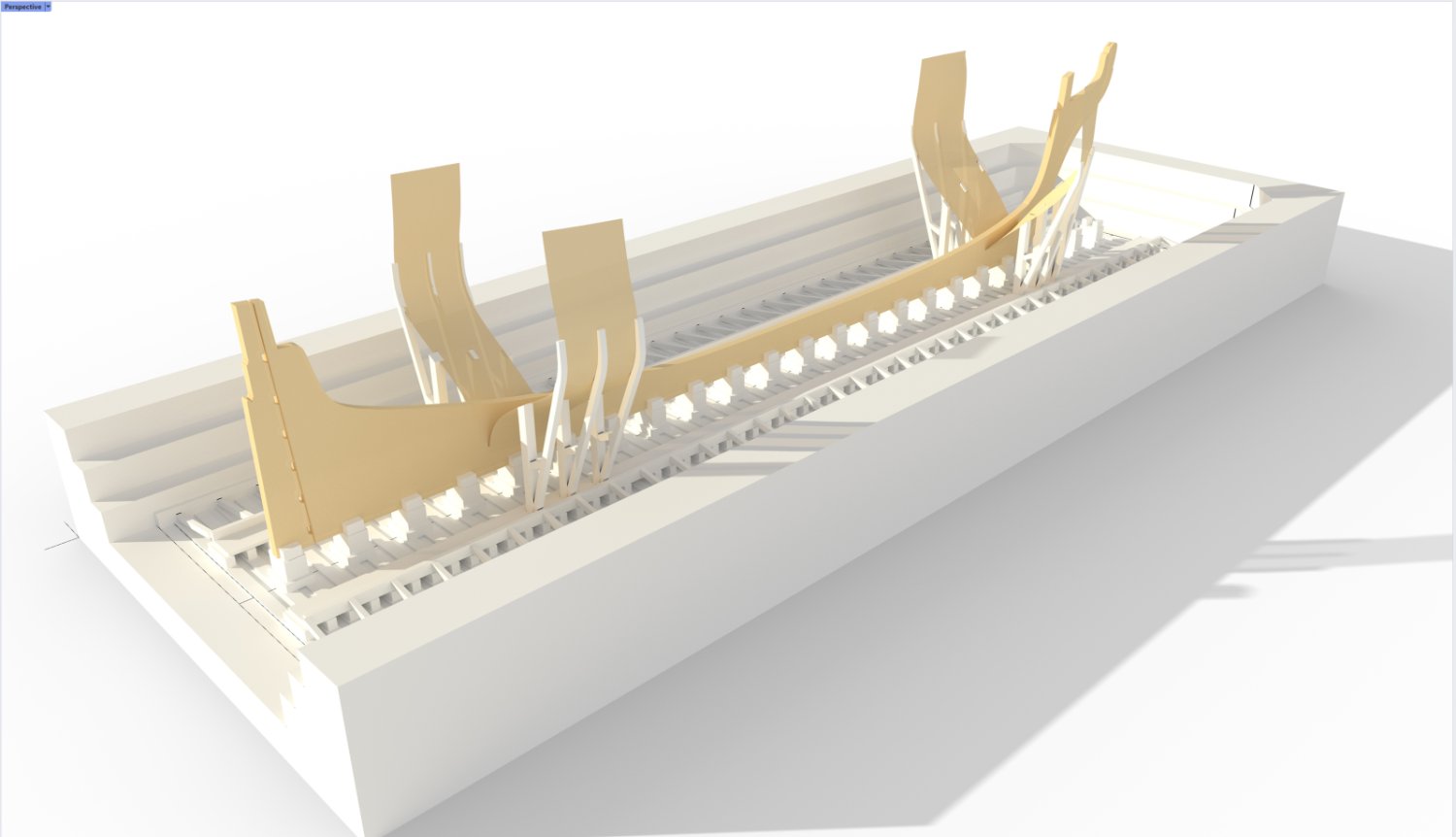
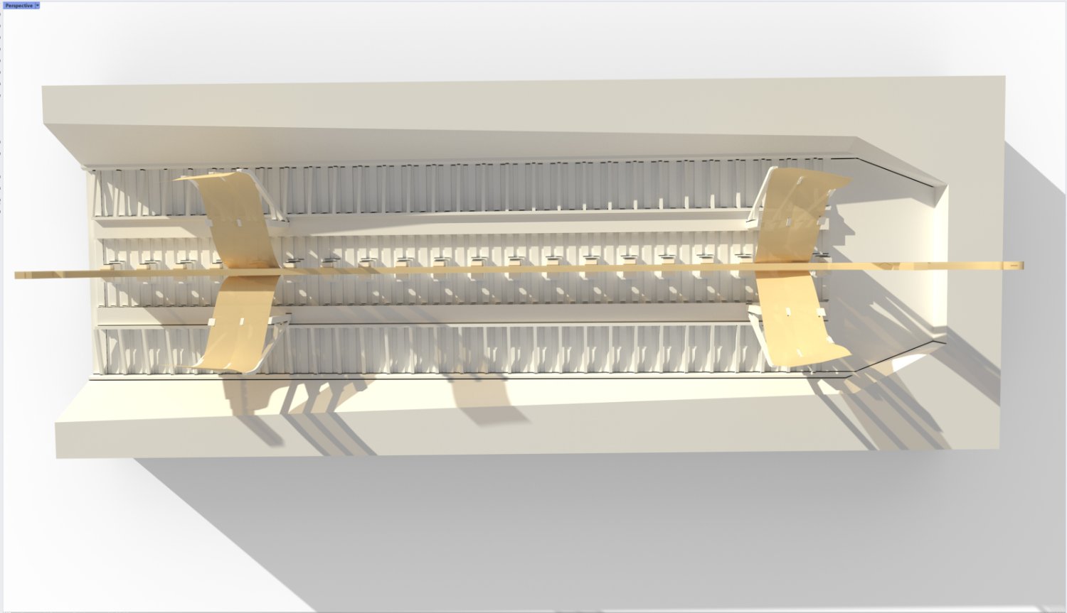
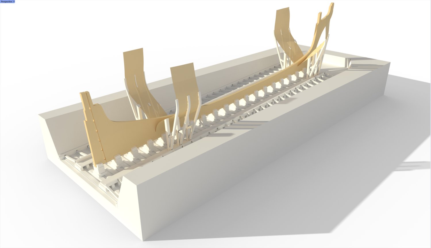
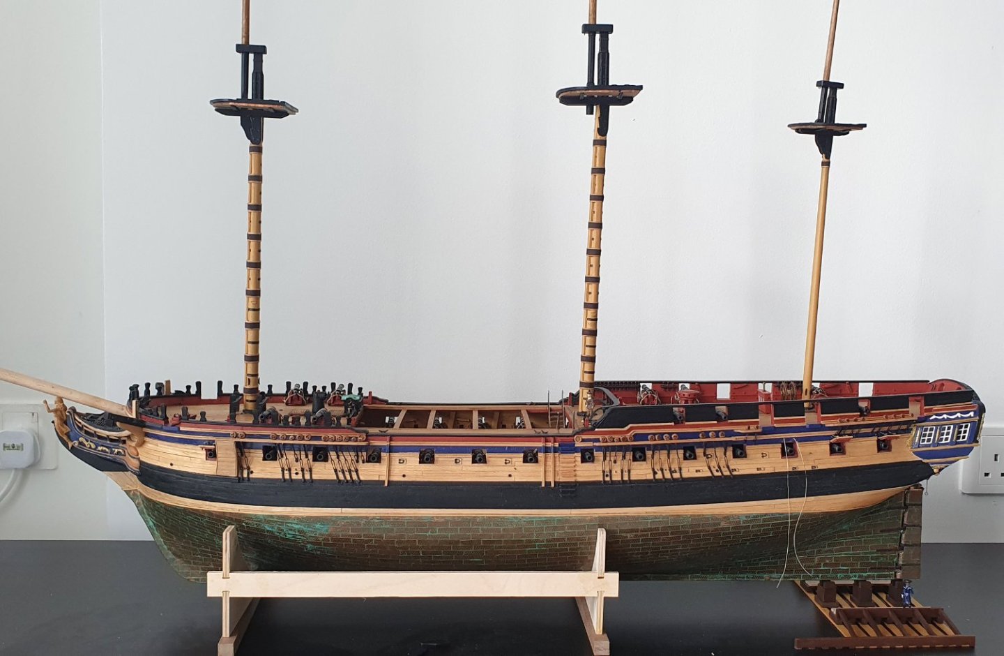
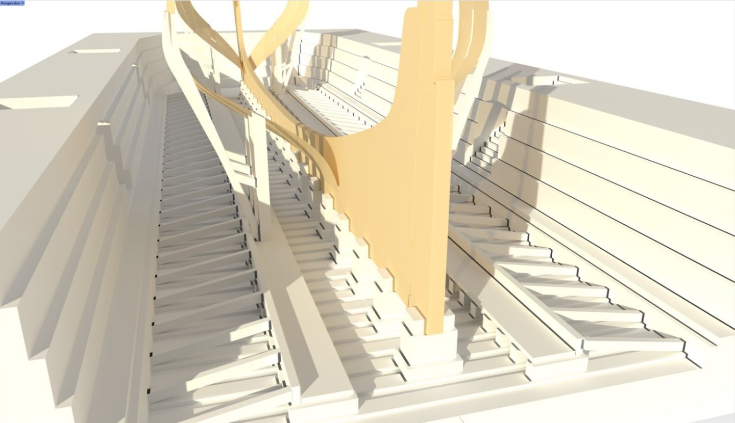
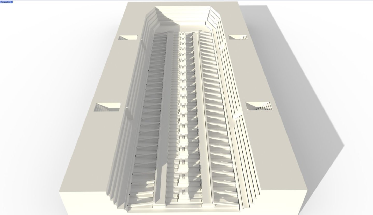
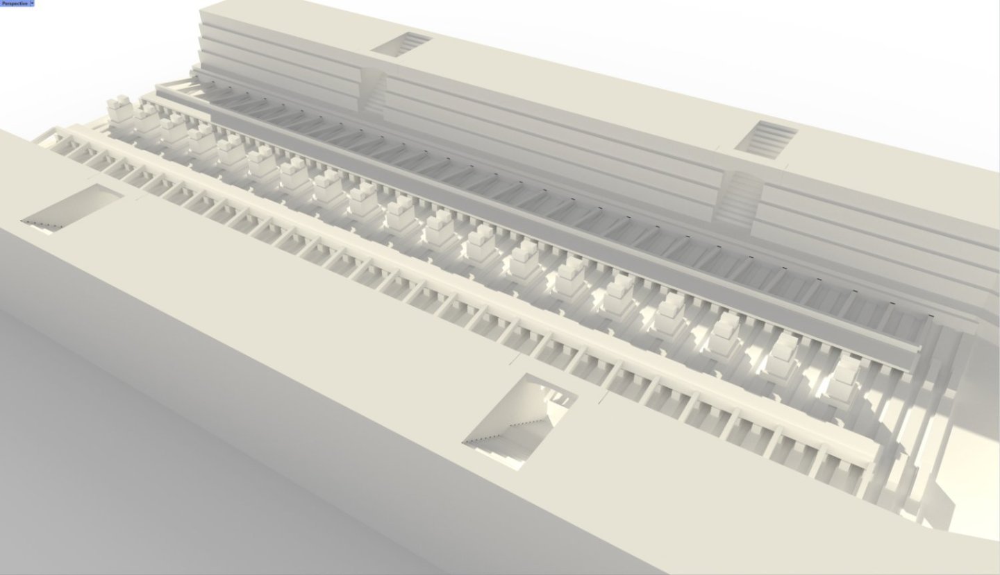
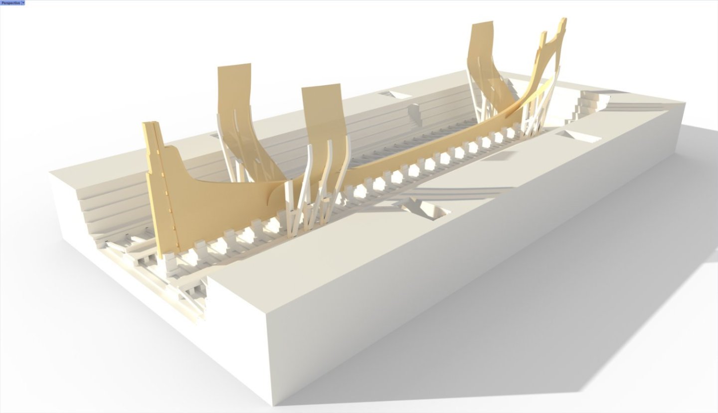
I continued to potter about with the display stand. I decided that I was not find of the slipway with sloped sides in no small part to the fact that it would be hard to construct. I thought that a hybrid drydock/slipway would be more my liking. As this is not meant to be historically accurate it gave me free reign to incorporate anything I felt like. The first effort was a tad deep so I reworked it to make the sides lower and I think that I should probably stop with the virtual world at this point and think about how to build it in the real world. First off, I have to source some sizeable timber planks as the biggest I have at the moment is only 5mm thick. This is proving to be more difficult than I first anticipated as I only need a small order and what is on offer would require a small truck to transport. I think that I have spotted somewhere that deals in more modest quantities but I will have to pay a visit to see what they have in hand. While I ponder my next move on this, I thought that I should go back to working on the much neglected ship. I carried on where I had left off which was the lower main mast. I used Dunnock's advice and used the plane on a beech dowel to get it down to a more manageable size while ensuring that it remained straight. I then I finished it off in the mill and lathe. Third try was a charm. I fashioned the front and side fish from some maple and milled out the filling pieces from beech dowel. Metal bands were the supplied black cartridge paper cut into 2mm thick strips. Wooldings were added using 0.5mm Ropes of Scale dark brown rope. The protective timber hoops were 0.5mm thick cherry soaked and bent around a curling iron. Cleats were added at the base as per the AOTSD drawings. I had to modify the mast hole in the quarterdeck as the front fish extends all the way to the orlop in the Steel and AOTSD drawings although I cheated a bit and stopped this at the upper deck. This is not a disaster as it is not visible and I had no good access to make the hole in the upper deck any bigger. My head section looked a bit odd. When I was double checking the dimensions and proportions against the Steel drawings, I realised that I have bungled the head section on all of the lower masts. I had made them square in plan and introduced a taper to all four sides but on closer examination the taper is only pronounced on the port and starboard sides and the geometry of the head section goes from rectangular at the hounds to square at the head. This meant that I had to run the lower main mast through the table saw and dowel in a new head section using some 2mm diameter brass rod. Luckily this is going to be painted black so I could use another timber as I only had walnut that was a suitable size. On the plus side it was easier to incorporate all the fiddly details when it was not attached to the rest of the mast. I think that building this separately would be the way to go, even if I had not botched the initial try, as you have a lot more control rather than trying to lathe and mill the entire assembly out of a single dowel. I added the battens and iron hoops using maple and cartridge paper. I had to scratch build the cap as the supplied one was not quite dimensionally correct and had two circular holes rather than the square and circle. I used this opportunity to add some bolts in the pattern suggested by Steel. These were 0.8mm brass rod filed down almost flush. The eyebolts were located according to the Steel and AOTSD drawings. I now need to move back to the fore mast and modify the head section to match the geometry of the main mast. Nothing worse than having to redo that which you thought was completed.


-
Thanks Jason. I have the Lavery book but it completely slipped my mind that he had a section on dockyard models plus a great photo of the Bellona on the cover. I had a look at the book today and reworked the CAD model to be more in keeping with the Bellona example as shown below in the before and after pictures. Needs a bit of refinement still and I should probably reduce the slope of the slipway a tad so that the model sits a little more horizontal. Regards, David