HOLIDAY DONATION DRIVE - SUPPORT MSW - DO YOUR PART TO KEEP THIS GREAT FORUM GOING! (Only 13 donations so far - C'mon guys!)
×


DavidEN
-
Posts
136 -
Joined
-
Last visited
Content Type
Profiles
Forums
Gallery
Events
Everything posted by DavidEN
-
Thanks for the link Dave. I am currently living in Malaysia so finding a company that will deliver here is challenging. It looks like the firm you have recommended delivers internationally so I may give them a go. Regards, David
-
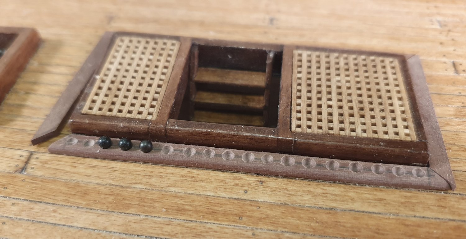
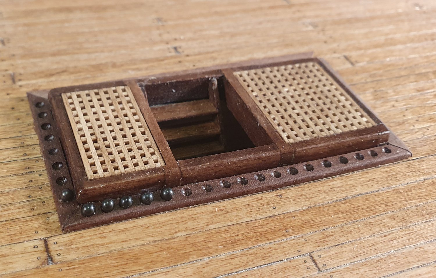
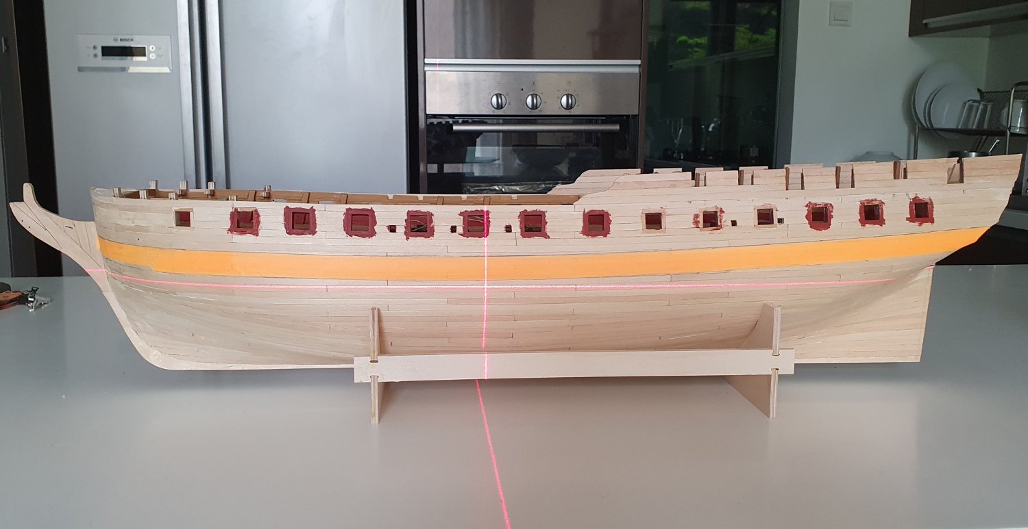
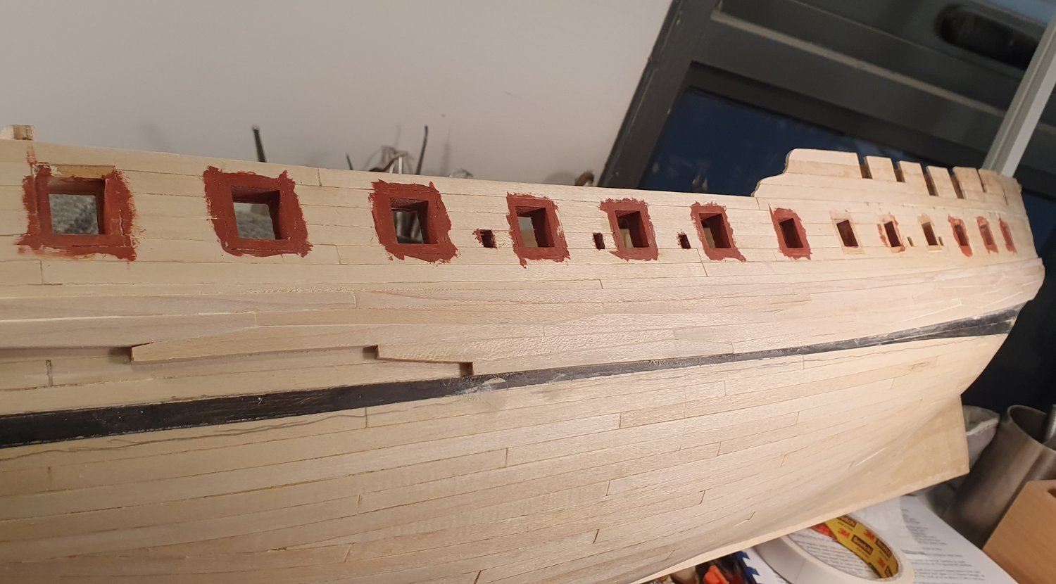
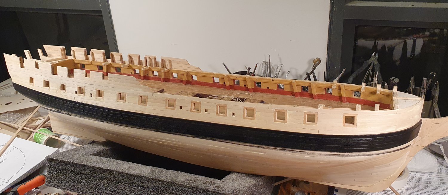
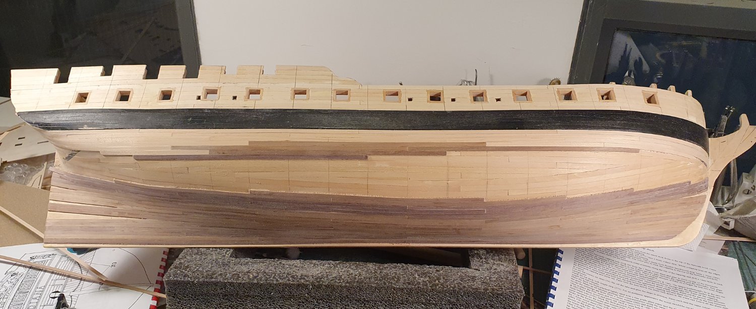
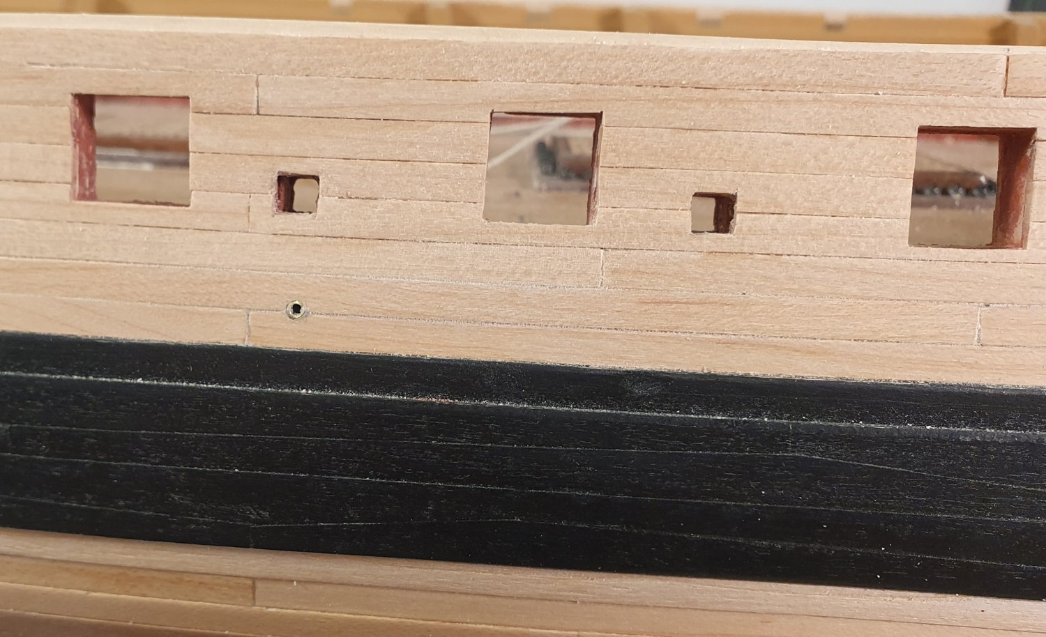
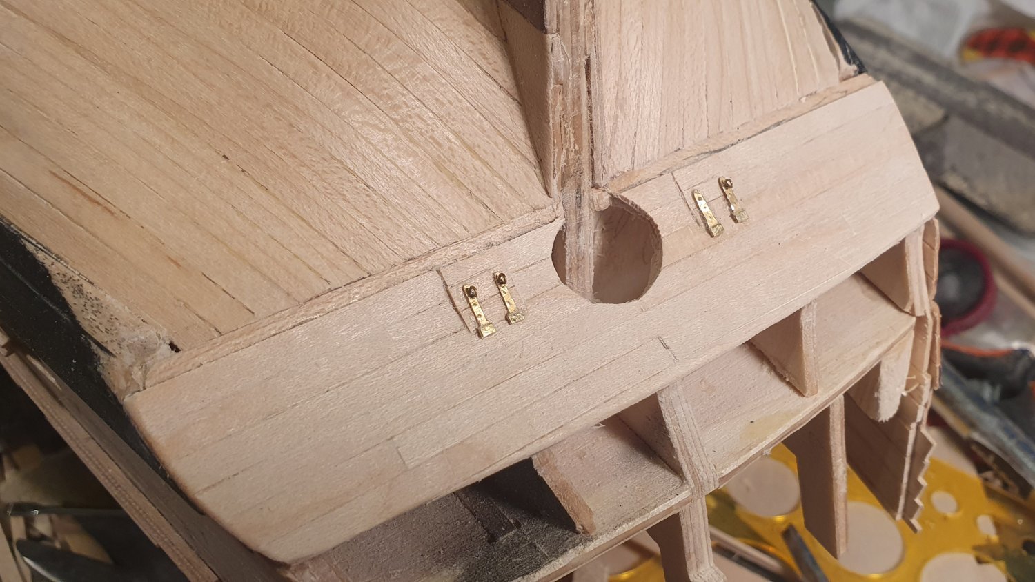
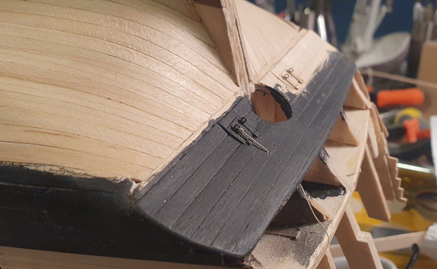
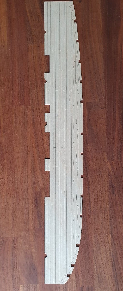
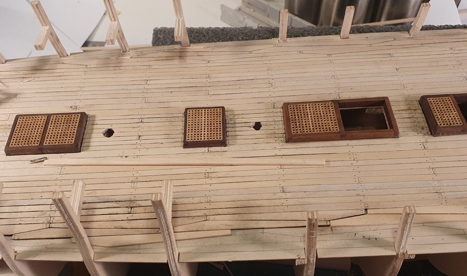
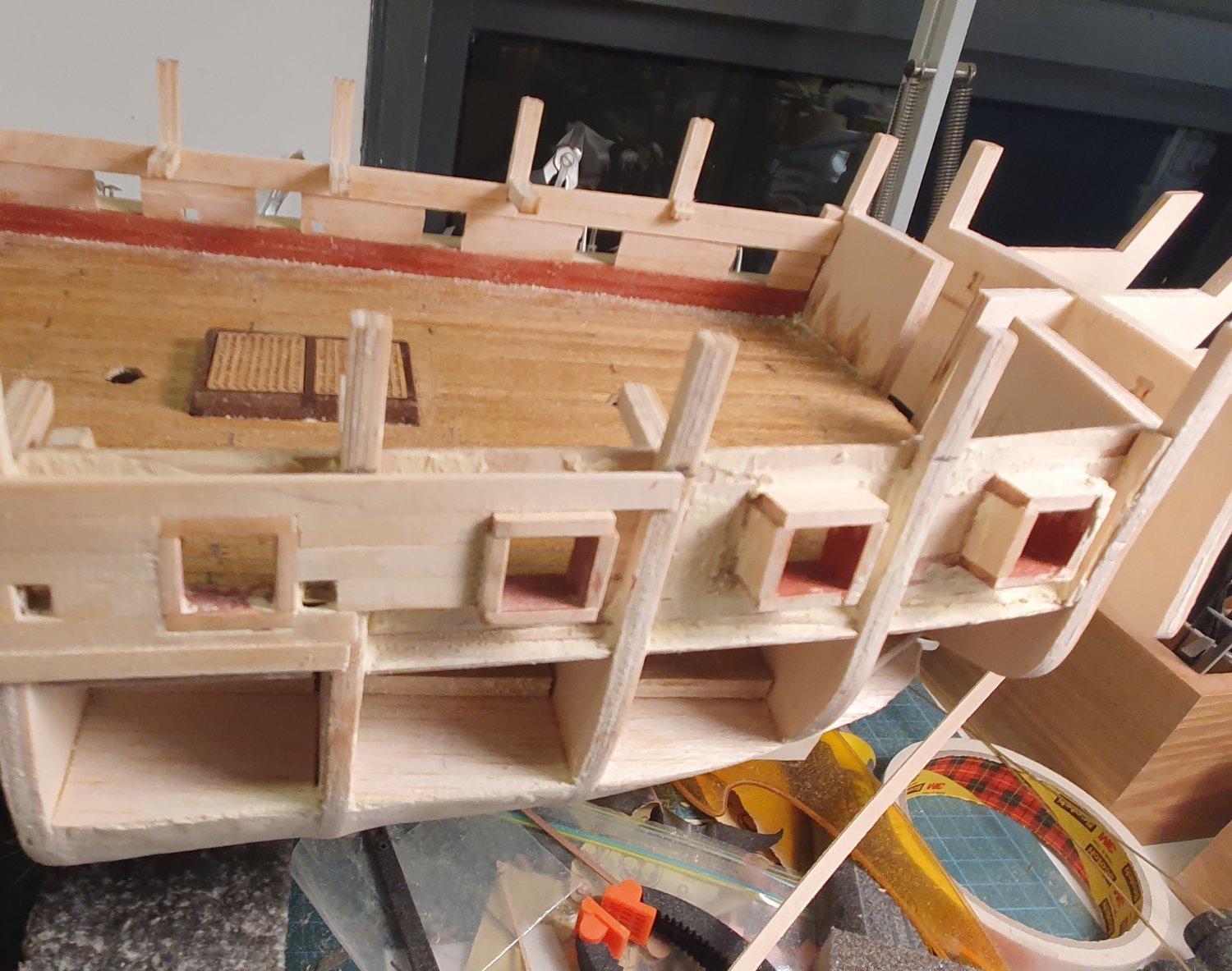
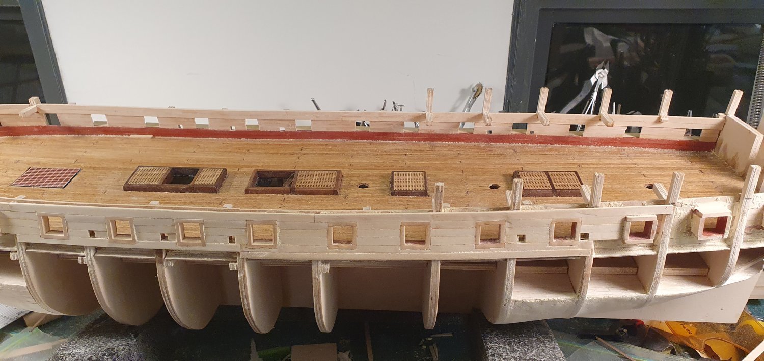
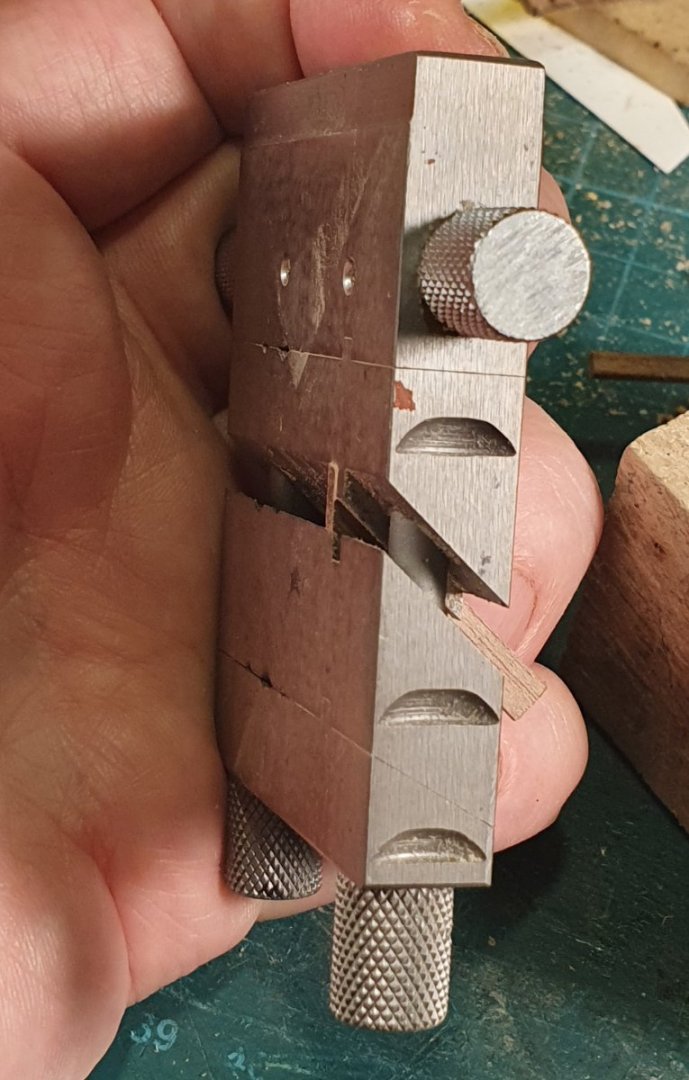
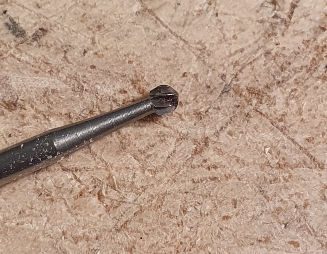
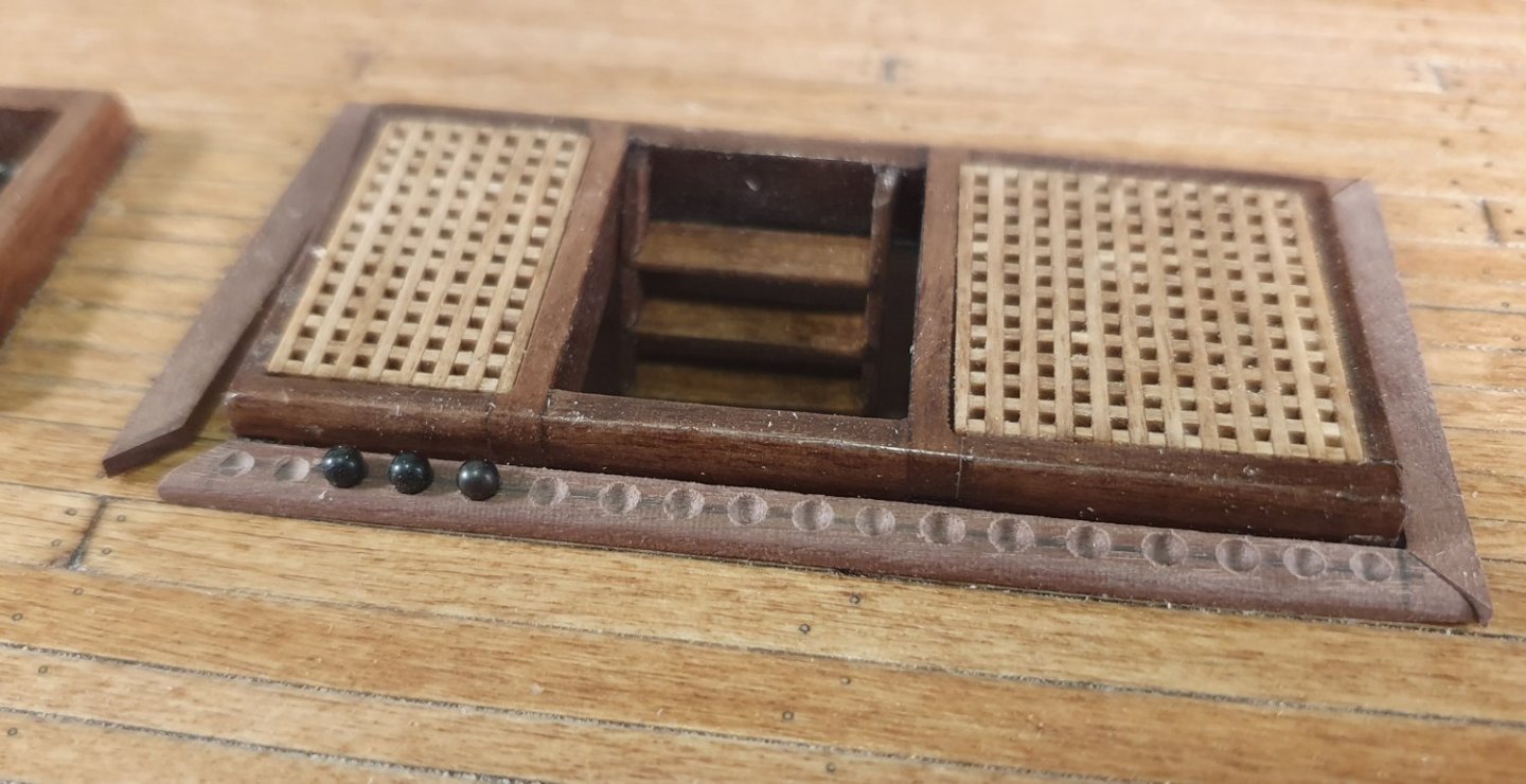
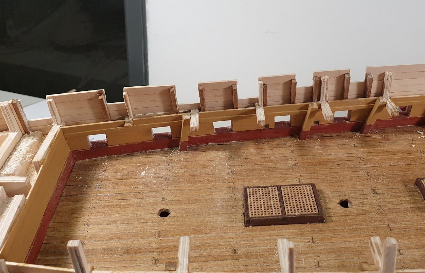
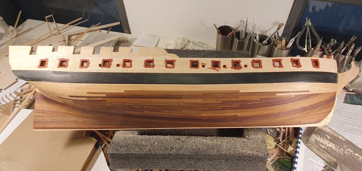
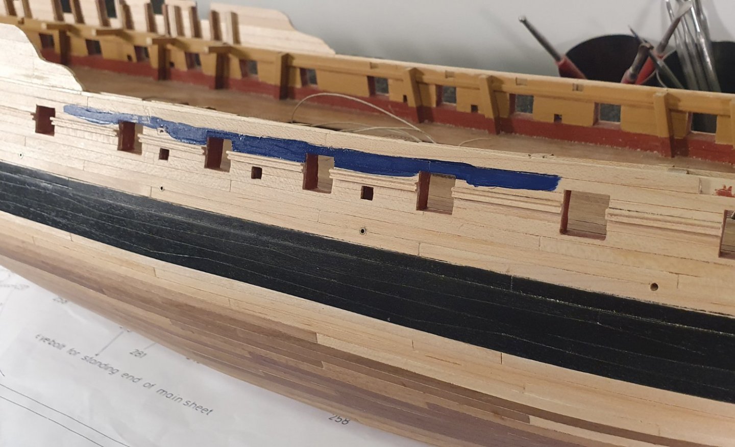
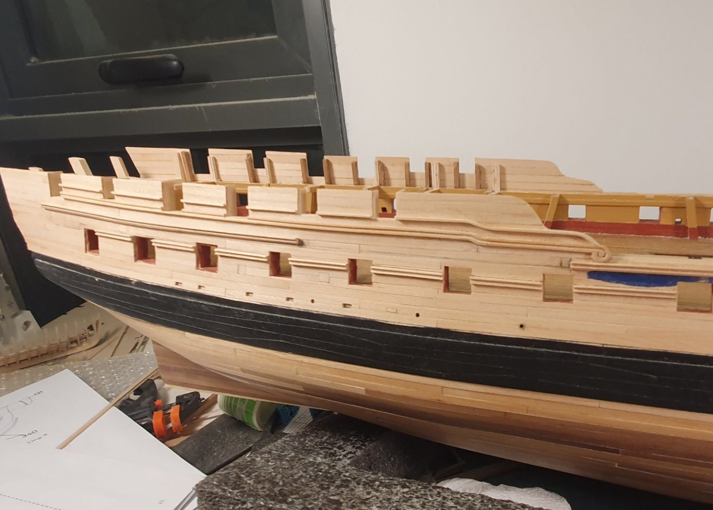
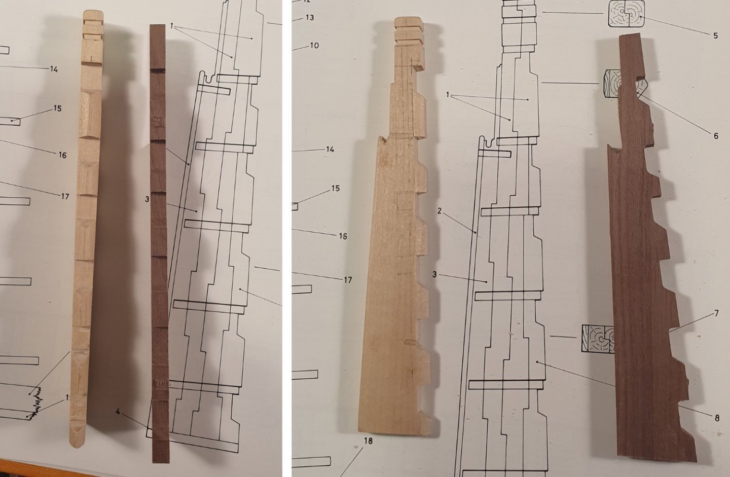
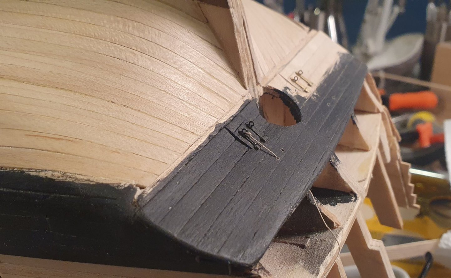
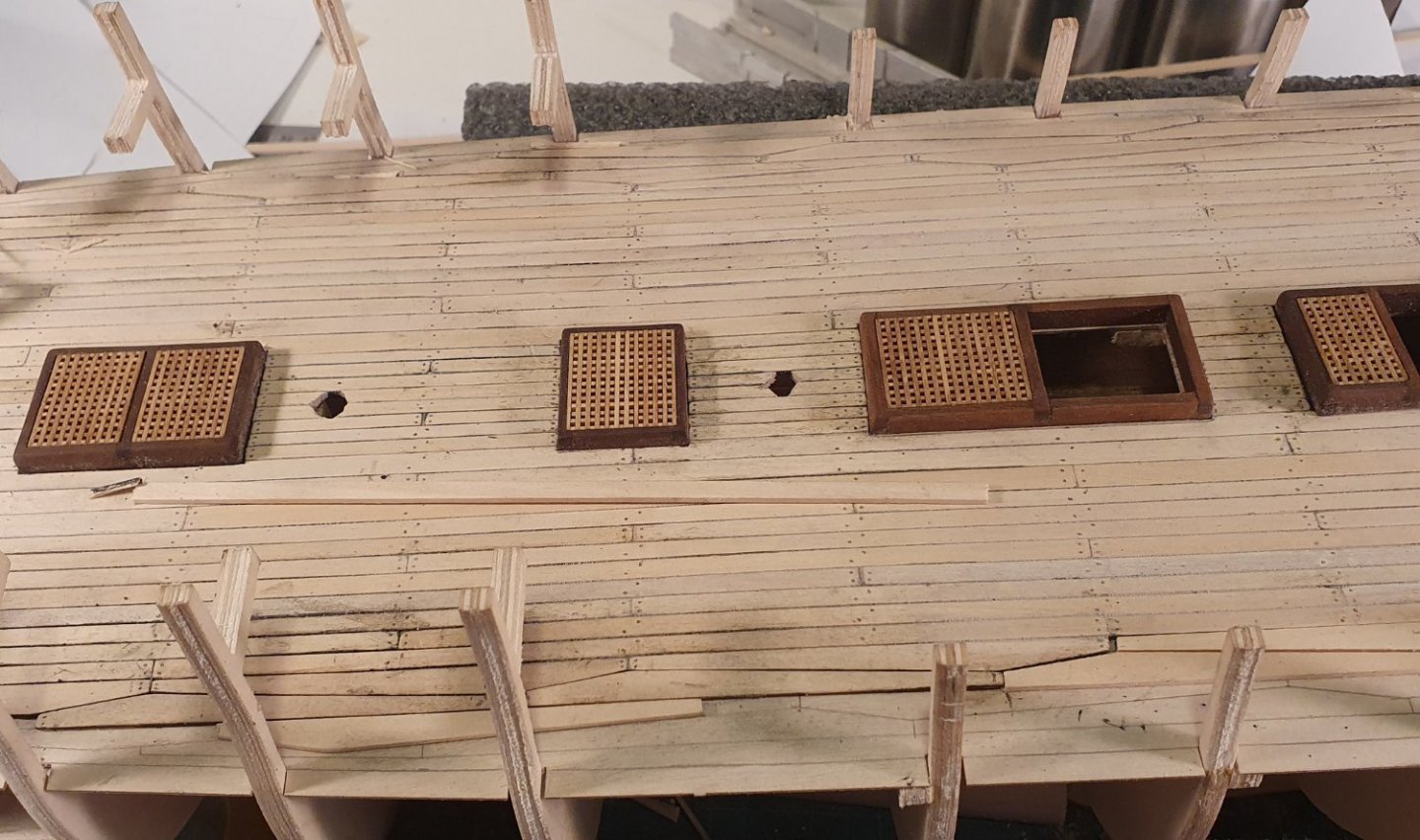
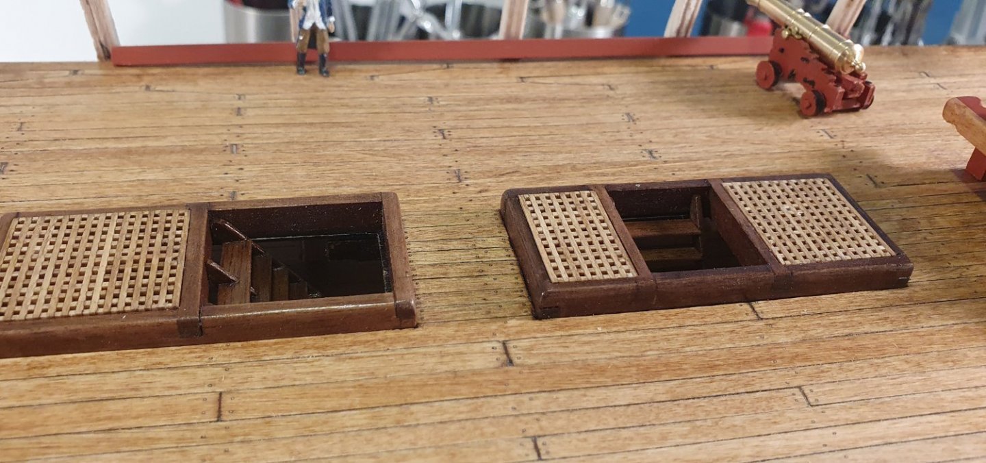
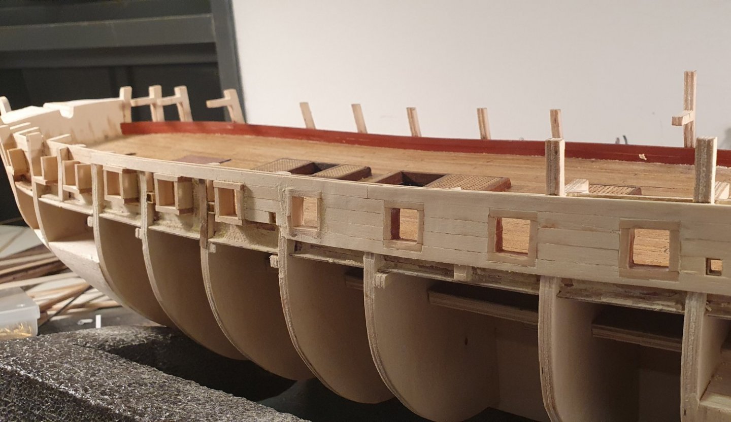
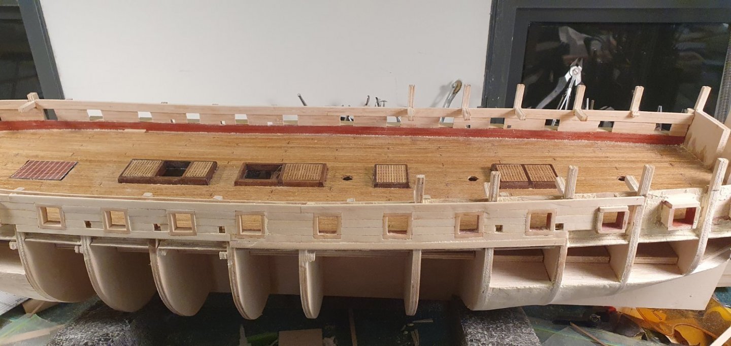
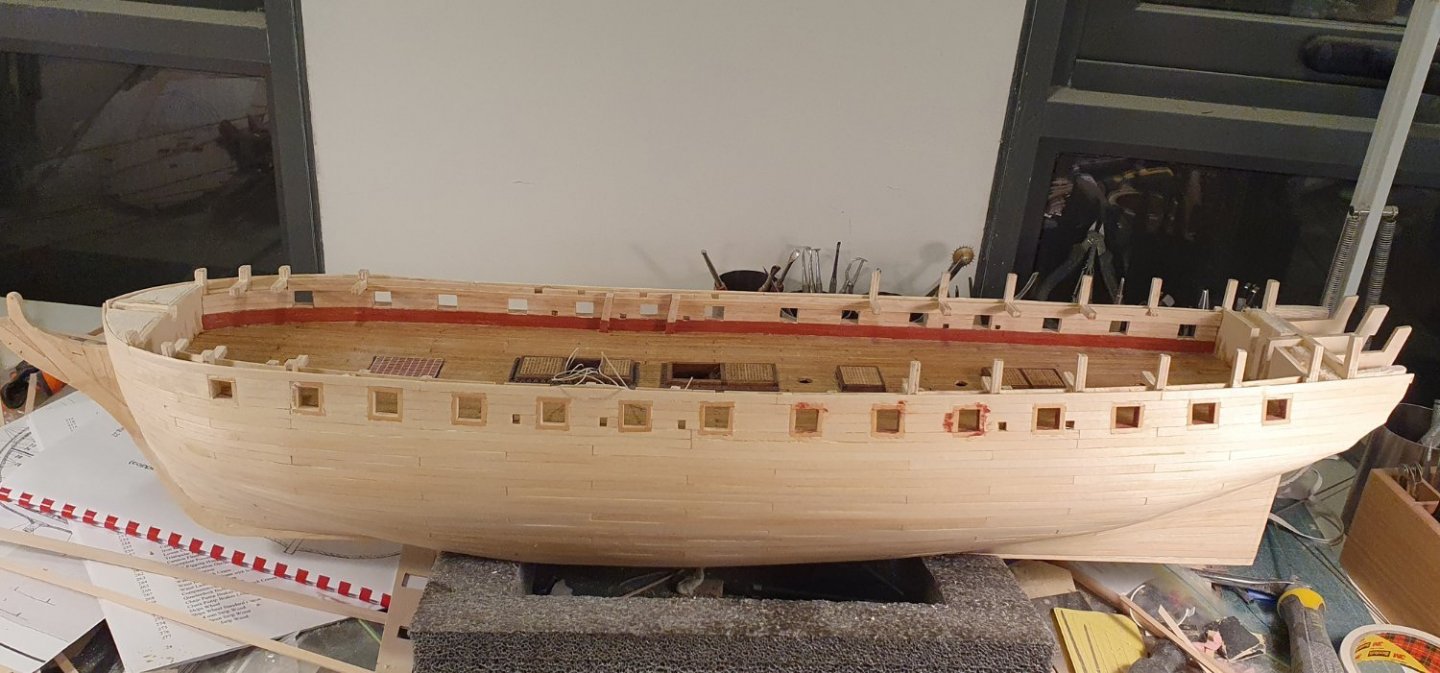
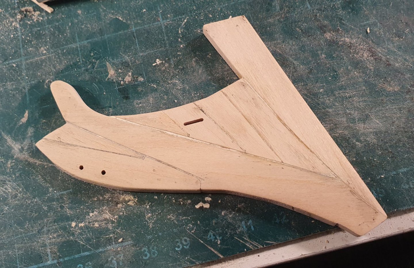
I added the shot lockers around the hatchways. These were constructed using 1.7 x 4mm walnut strip. The corners were fashioned using a jeweller’s mitre jig and the dimples were excavated using a 2.1mm diameter spherical mill bit. I made a slight blunder by using the kit supplied 2.5mm cannon balls. In a fit of pedantry, I had ordered 2mm diameter balls to more accurately represent the 5inch diameter ball used for an 18 pounder but when it came time to install them, I must have picked up the wrong packet. It was now decision time. Do I go open or closed bulwarks on the quarterdeck. The open ones look a lot prettier but after much dithering I decided on the closed bulwark option as I figured I could hide a multitude of sins behind them. The decision being made I marked up the positions of the gunports. I had to adjust these to reflect my somewhat arbitrary gunport positioning of the deck below. I then added additional framing and cut back some of the existing bulkhead framing where it coincided with my new gunport location. I then added a first layer of planking to the outside of this to match the rest of the hull. I temporarily relocated to the kitchen to mark out the position of the wales and the waterline to set me up for the second planking. I used a laser level to mark out the waterline. I guess I could have used the traditional pencil shoved through an upturned paper cup but this way I can legitimately claim that the model was built using lasers. This line will eventually be covered up with the second planking but it is useful to mark it is as above the line the planking will be visible and I have to proceed with caution while below it will be covered with copper tiles so I can run wild. I proceeded to plank the wales with top and butt planking. I noticed in the AOTSD drawings that the top and butt planking continues below the wales. This seems quite fanciful to me. If you look at the detailed section in the AOTSD book, the planking below the wales consists of thickstuff and them five diminishing strakes. To achieve this profile using top and butt planking would be very challenging from a practical standpoint although not impossible. I can't be bothered to do any further research on the matter and I just proceeded with normal planking as I would not like to attempt that pattern in the complicated stern section. I then painted the wale black. I also painted the thickstuff above the wale black. This could be construed as quite a controversial move but the 1794-3 model has this colour scheme so I can claim precedent. Planking below the waterline transitions from maple to walnut as I had a lot more walnut to hand. It was touch and go as to whether or not I had enough maple to finish the upper planking. Turns out I did but only just and I finished with half a plank to spare. I added the scupper pipes at this stage. These will have a cover ring placed over them. I will probably use the PE part included with the kit. I only fitted the scupper pipes to carry through the internal bulwark at one location as it proved to be quite difficult and not that visible. I gave the hull a splash of the French Blue from the Jotika Admiralty paint collection. I confess that I am not that keen on this colour which also has an unusual gloss to it. I prefer the blues used by the various other Diana builders on this site. It is unfortunate that the timing of this coincided with one of those Covid lockdown periods which meant that the hobby shop was closed down for a while so I decided to just plough ahead rather than waiting. I still have not grown to love it though. I am hoping that once all of the masts and rigging are installed it will appear less jarring. I didn't like the cast moulding rails supplied with the kit so have been experimenting with the various hull profiles that I milled out of some lime strips. I wish I could get my hands on some boxwood as it would give a better edge but I have not managed to source a local supplier yet. I am not planning on painting the planking above the wales so the supplied walnut rudder does not match. I had to fashion a new one out of a 10mn thick lime plank. I used the AOTSD drawings for reference and this did allow me the opportunity to add the taper. I started planking the lower counter in anticipation of tackling the rear elevation which will be the subject of the next post. You may notice that the holes drilled for the ropes attached to the hatch covers do not line up. I eventually noticed it 6 months later. They now line up.


-
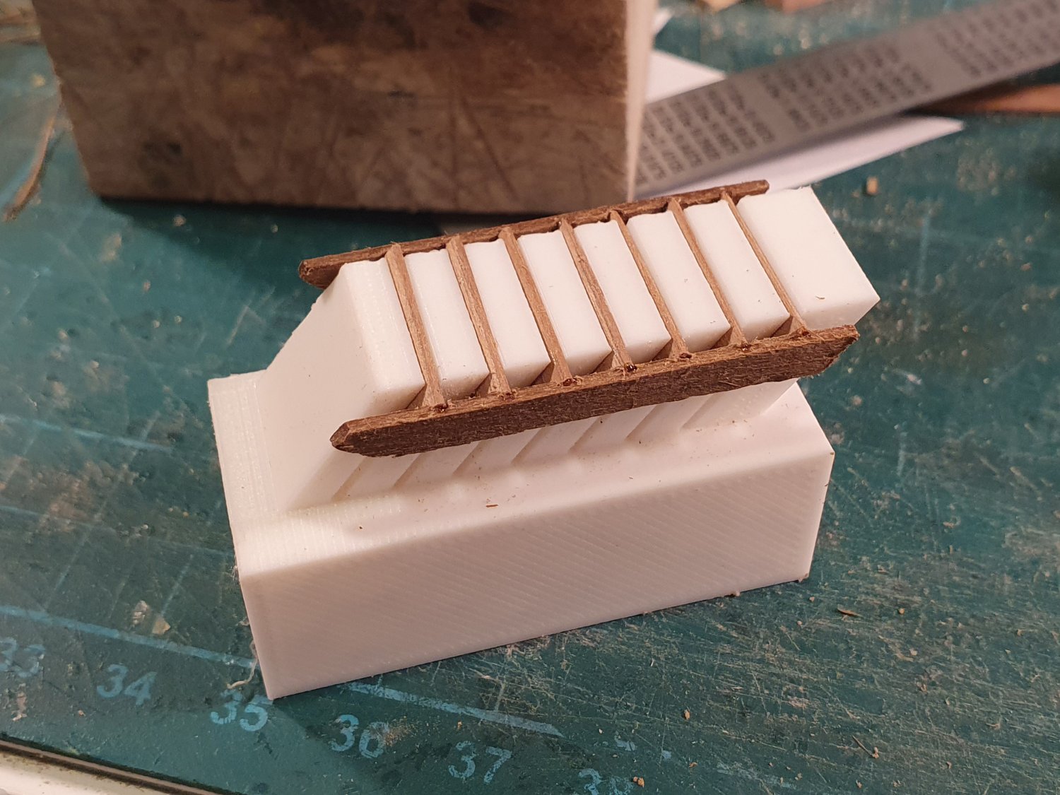
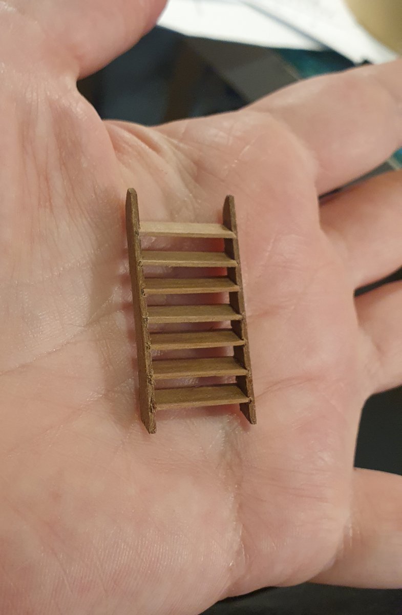
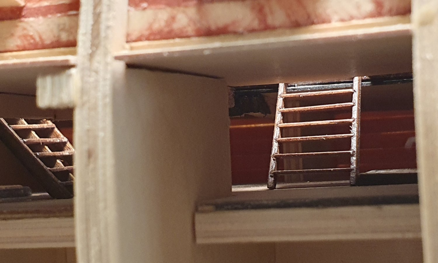
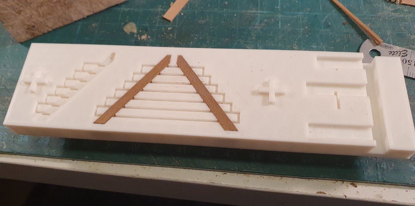
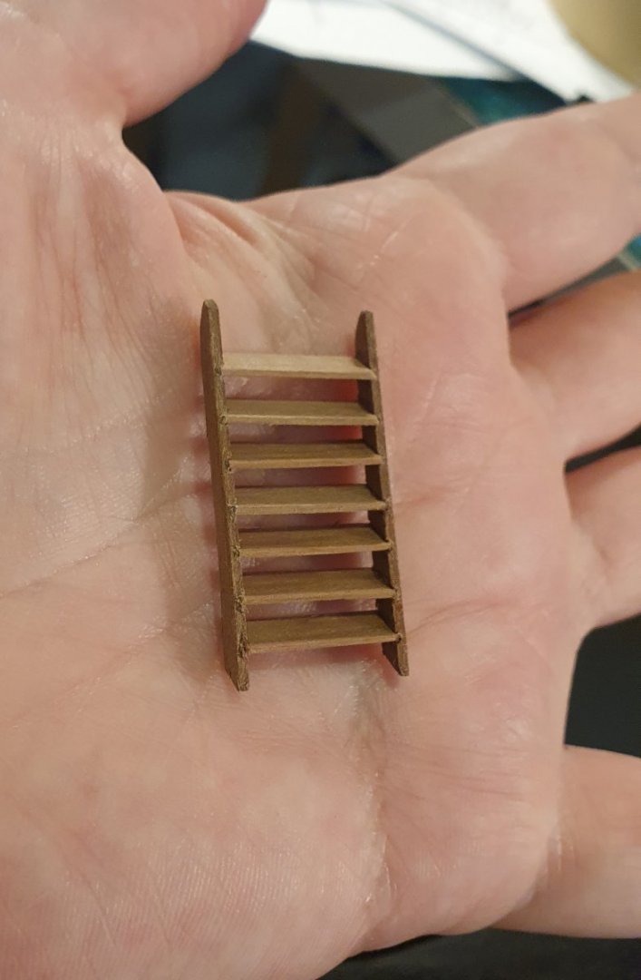
Thanks Dave. The ladder jig was born out of the frustrations of several failed attempts of trying to build the ladder freehand. No matter how carefully I measured they always came out with a dangerous looking sideways lean.
-
Thanks for the link Bob. I was having trouble locating them. Regards, David
-
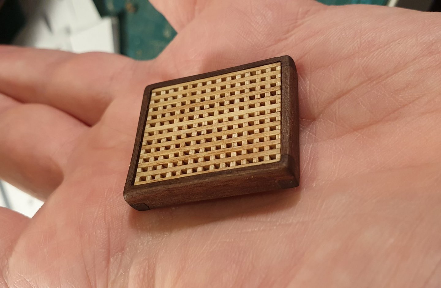
Hi Allan, Thanks for the kind words and additional information. I did read somewhere that the gratings should be oriented in a fore to aft direction however the ship has already sailed on that decision so to speak. The gratings are well glued in and it would not be possible to remove them at this stage. The silver lining is that they are all oriented in the same direction so it is at least a consistent error. When clicking on the link I can only find the three drawings of the Seahorse in the list. Still it is a very useful resource to have access to. Regards, David
-
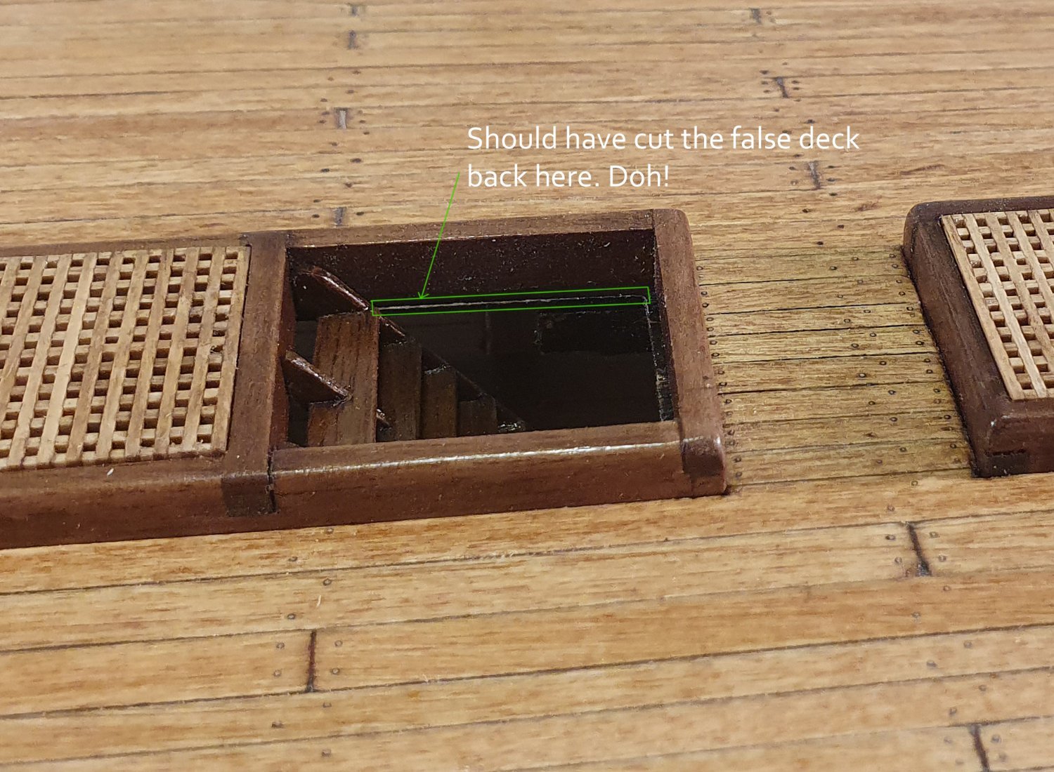
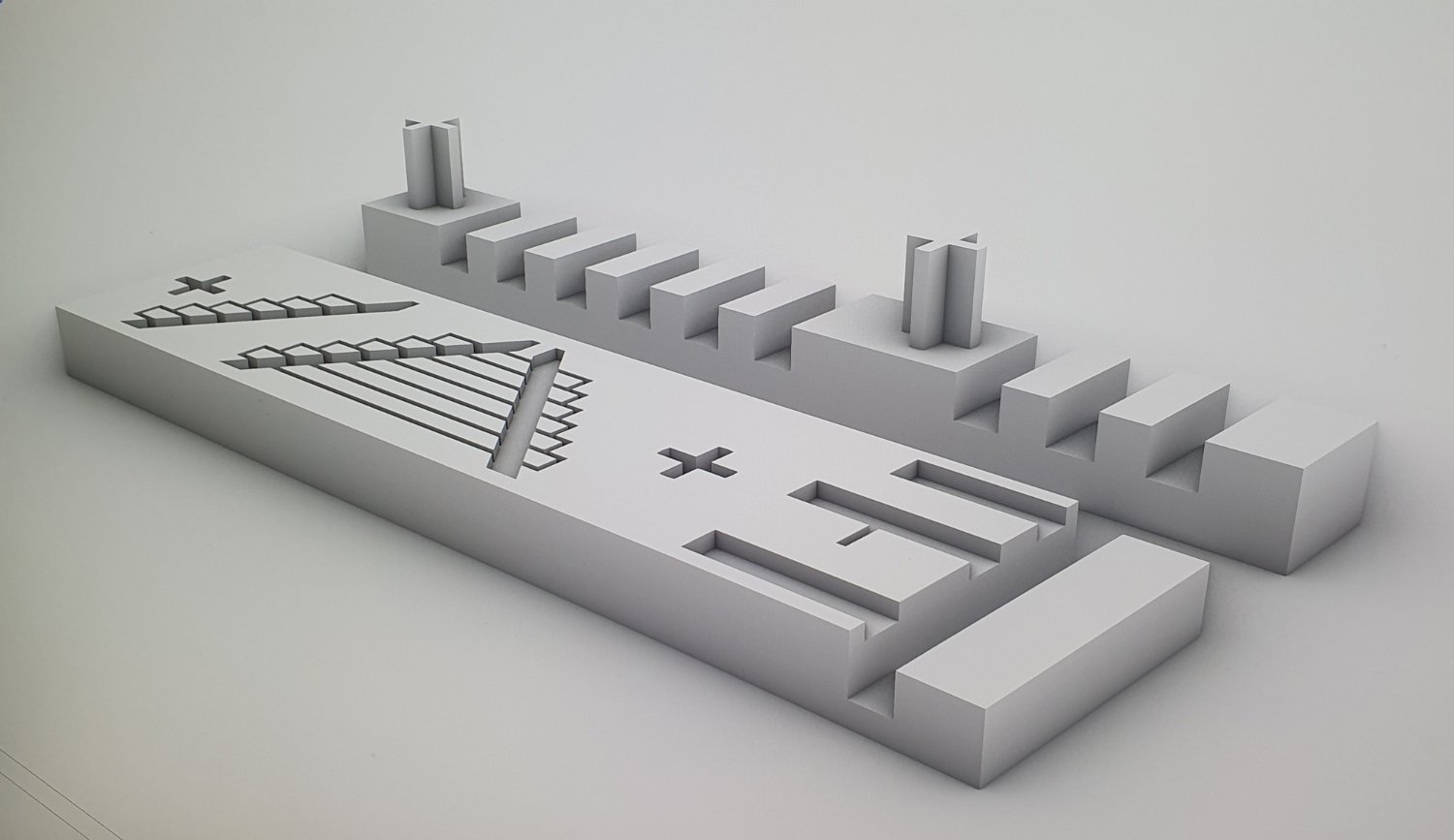
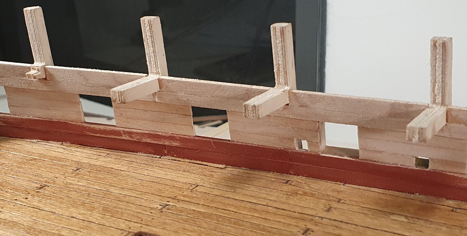
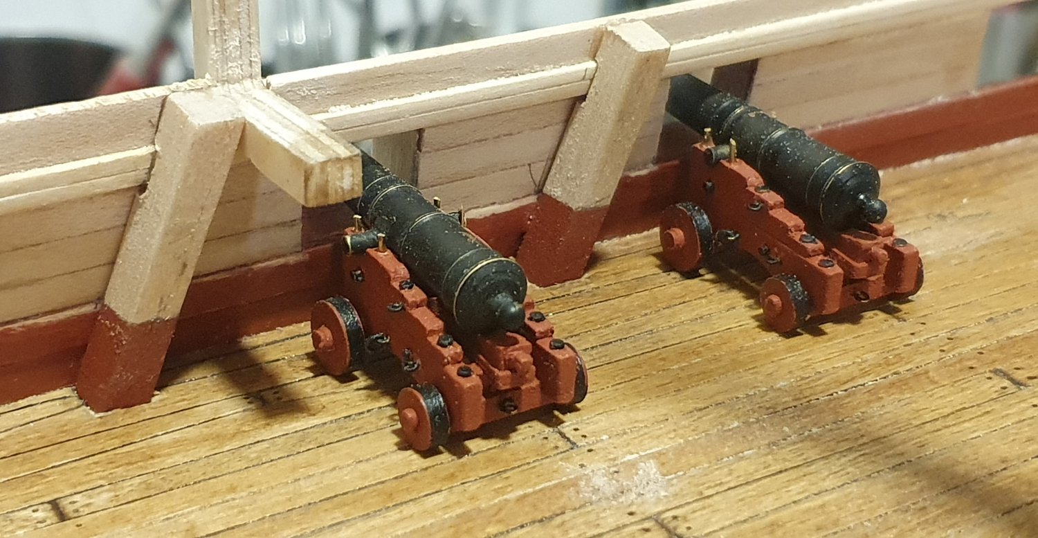
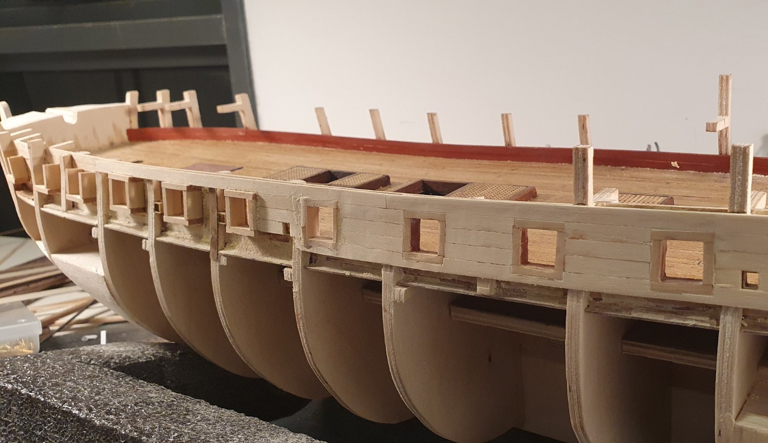
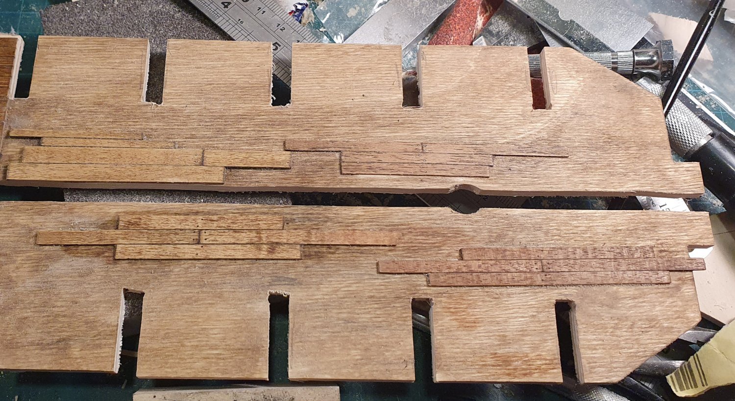
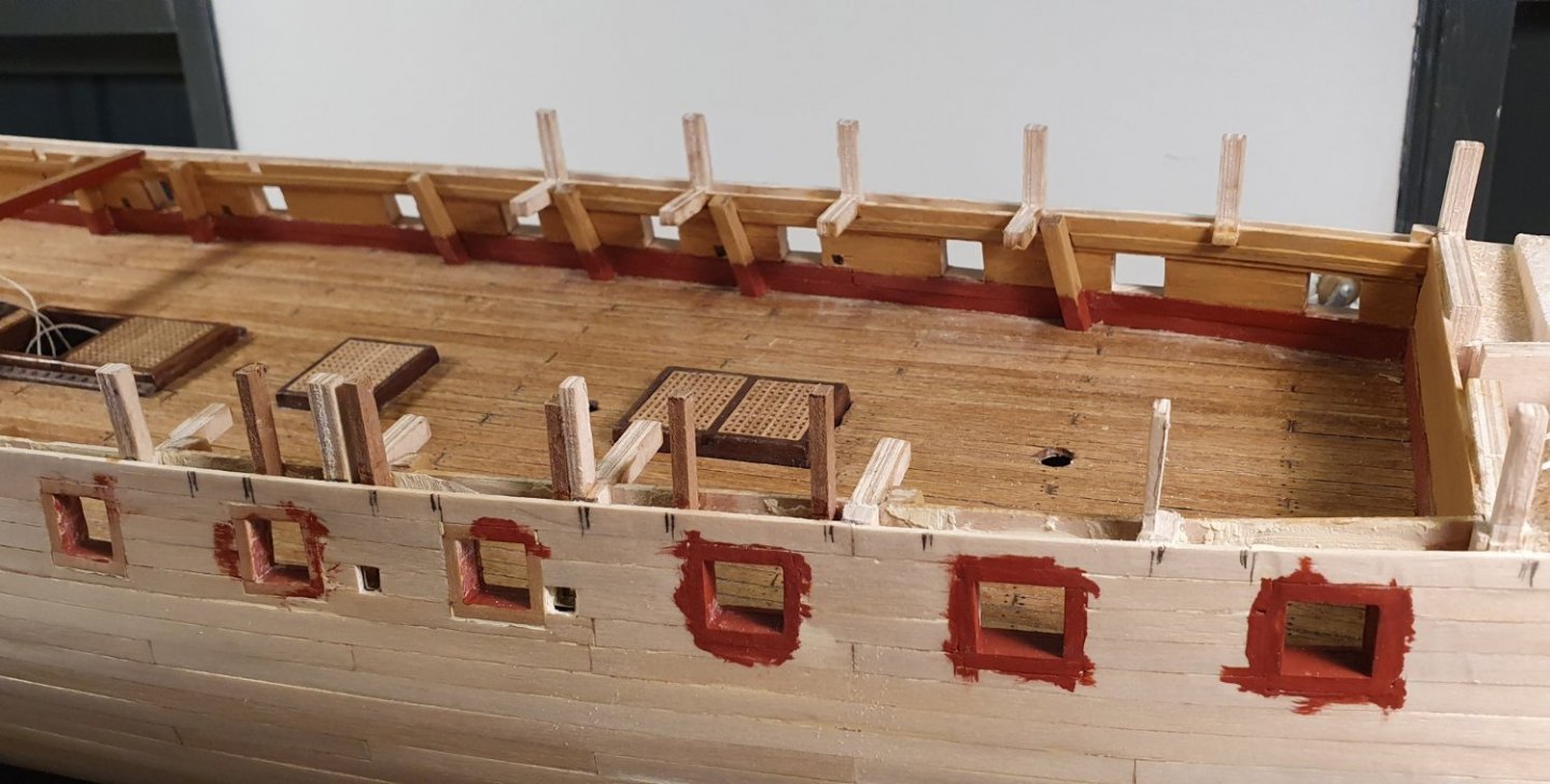
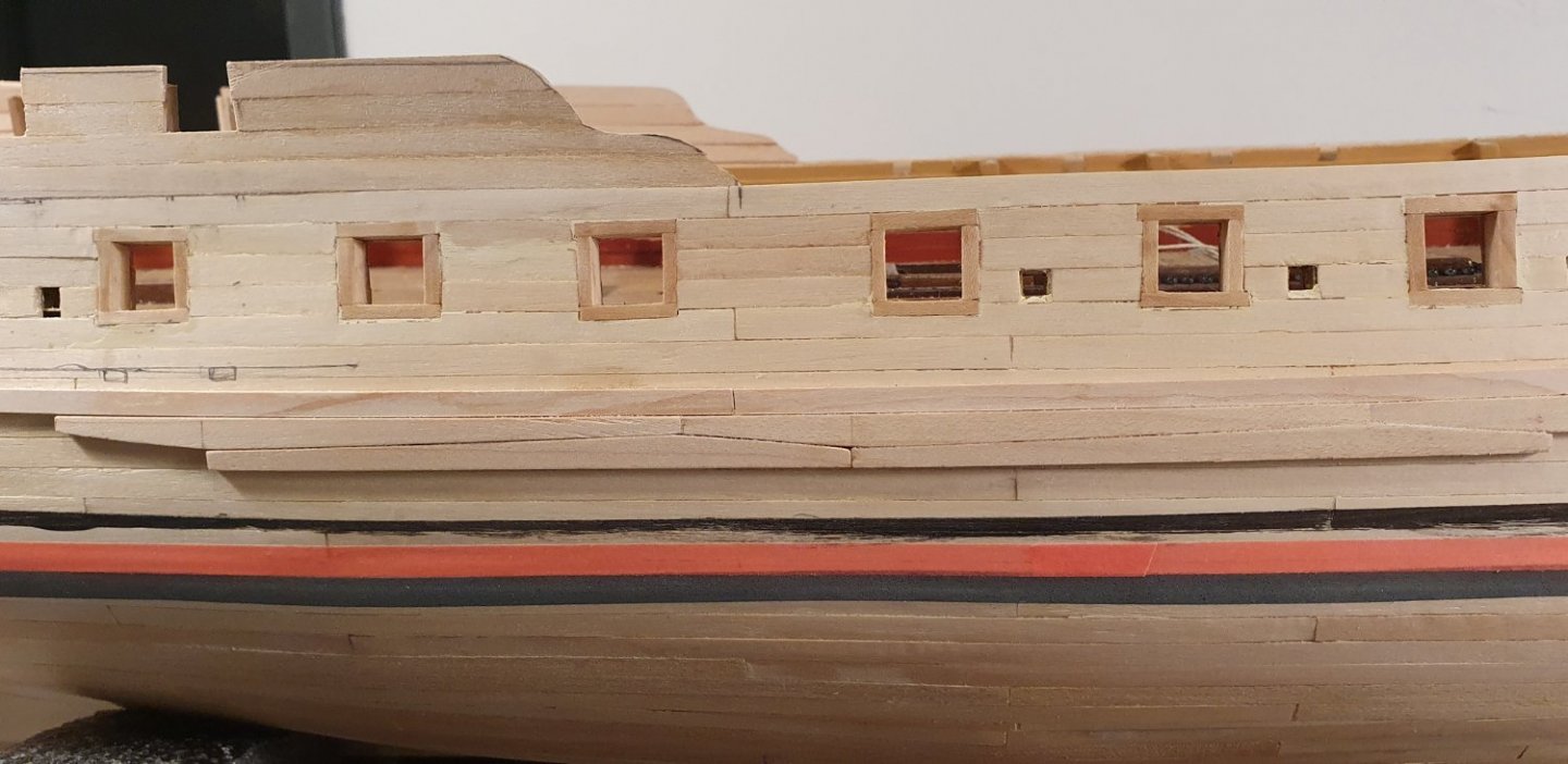
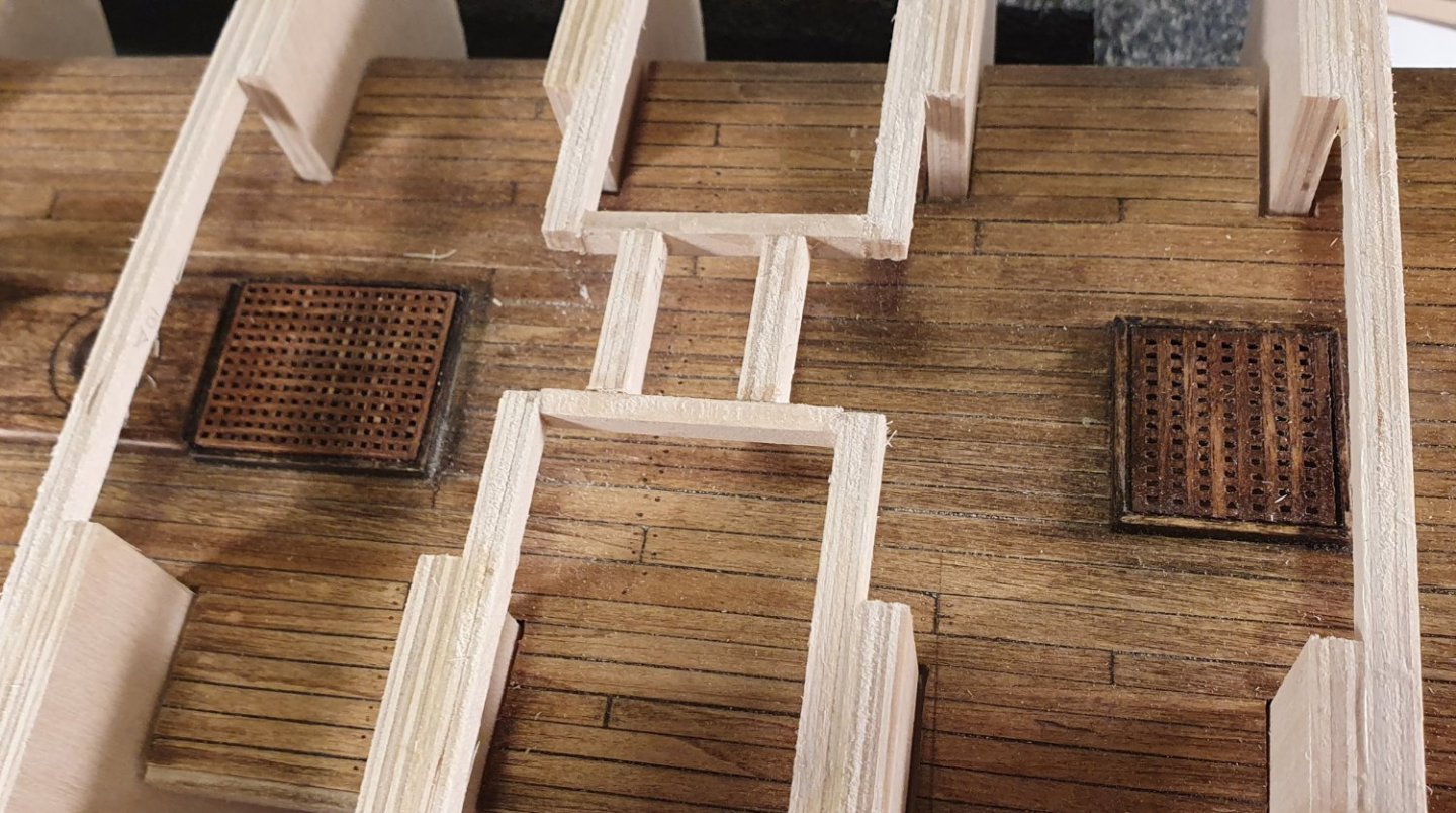
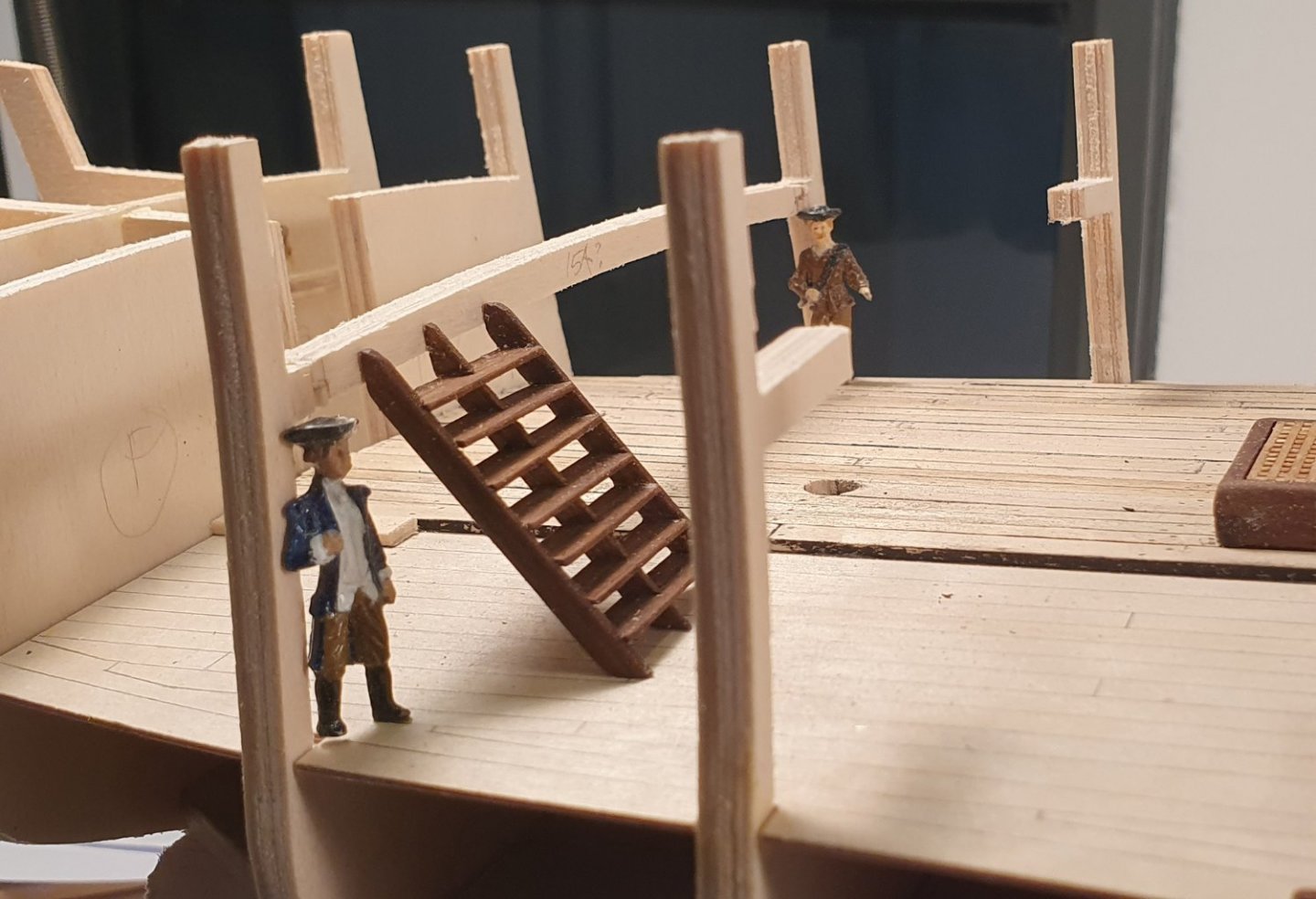
I started on the installation of the gun deck. I drew the planking pattern onto the false deck and then cut it in half lengthways for ease of fitting. I plumped for the top and butt planking for this deck noting the ambiguity in the AOTSD drawings. When placing the false deck on the model I noticed that some of the beams passed through the hatch openings. I relocated these with an inelegant detour although they would have had enough structural integrity as cantilevers and I probably could have gotten away with just cutting them out. I made up the hatches using the kit supplied gratings and used walnut for the coamings. I stained the gratings using Golden Oak stain although the wood used in the gratings does not take the stain that well. If I were to do it again I would cut the false deck back around the coamings so that the edge is not visible through the openings. I have just painted this black at this location but on the upper deck I cut the false deck back and introduced secondary beams for the coamings to sit on. I started on the ladders that go between the decks. I thought that I had been diddled out of these as I couldn’t locate them on any of the parts sheets. After making the ladders from scratch I discovered the kit supplied pieces on a small piece of ply that had become stuck to the back of another sheet of parts. Looking at the supplied pieces I do not think I would have used them anyway as they were fashioned out of poor quality splintery ply. I built a couple of wonky efforts before I decided to 3d print a jig which enabled me to get the grooves in both the stringers align with a higher degree of accuracy. I then made another jig to hold the treads parallel to each other when fitting them to the stringers. This holding jig was not that successful and requires some redesign. I used 1.5mm thick walnut for the stringers and 1mm thick walnut for the treads. I started to build up the inner bulwark using the AOTSD drawings as a reference. I knocked up a couple of gun carriages for reference so as to check the height of the gun ports as I went along. This is the first time I have had to deal with gun carriages and later on I will dedicate a whole post to them to highlight some of the trauma I experienced. There was a great clash between some of the gun port locations and the bulkheads. I tried to overcome this without resorting to major surgery by shifting the critical gunports to abutt the bulkheads and then dispersing the others more or less evenly in the remaining space. I did a lot of this by eye, being too lazy to measure everything exactly, but this cavalier attitude did come back to haunt me when installing the chain plates and channels. Having located the gunports on the inner bulwark I turned to the problem of how to position these on the outer skin of the hull. I noticed that a lot of builders complete the first hull planking and then cut the gunports out. I was not at all confident about my ability to achieve that with any reasonable degree of accuracy or safety so I decided to build the lining of the gunports directly onto the inner bulwark and then continue the first planking such that it butted against this lining. The thinking was that I could then dremel these linings flush with the first planking and hide the whole mess with the second planking. I think that the method itself is a workable solution had I gone about it in a slightly different way. What transpired was that I didn't account for the slight curvature of the hull and neglected to chamfer the sills of the gunport lining such that they lay parallel to the gun deck. If I was to do it over I would assemble the entire gunport lining off the model and then profile the one side to match the curvature of the hull so that they fit snugly to the ship with the top and bottom sills parallel to the gun deck. For the sweep ports I just used some 4x4mm square brass tubing to give me something to plank to. Once I got going the first planking was uneventful which I will not dwell on here as there are a lot better examples of how to plank a hull out there. I should note that after planking the first side I did pause to install the ladders, as well as the eyebolts to tie off the end of the rope handrails, while there was still access from the side. If I had waited I could imagine dropping one of these ladders into the completed hull and never being able to get it out again where it would be doomed to rattle about for all eternity.


-
Hi Jason, Thanks for the kind words of encouragement. I have certainly been following the build logs of other members. There is so much information and inspiration to be found there. I have been shamelessly pilfering ideas and details from your log for a while now as it is the gold standard for Artois builds. I do not know how you do it Even if I was building at a scale of 1:10 I couldn't hope to match the detail and workmanship you achieve. Regards, David
-
Hi Dave, Welcome aboard. Hull planking does seem to be a bit of a dark art. I think it will take another two ships before I begin to get the hang of it. It looks like you are progressing very nicely on your Endeavour. Happy building. Regards, David
-
Hi Allan, I have tried the drawplate method but I have never managed to achieve the smaller sizes without them disintegrating into a frayed mess. There are other nozzle sizes available. I think the smallest is around 0.2mm in diameter going up to 0.8mm in increments of 0 1mm. Changing the nozzle is not a simple task though and requires disassembling the print head to do so and I hear the smallest sizes are prone to clogging.
-
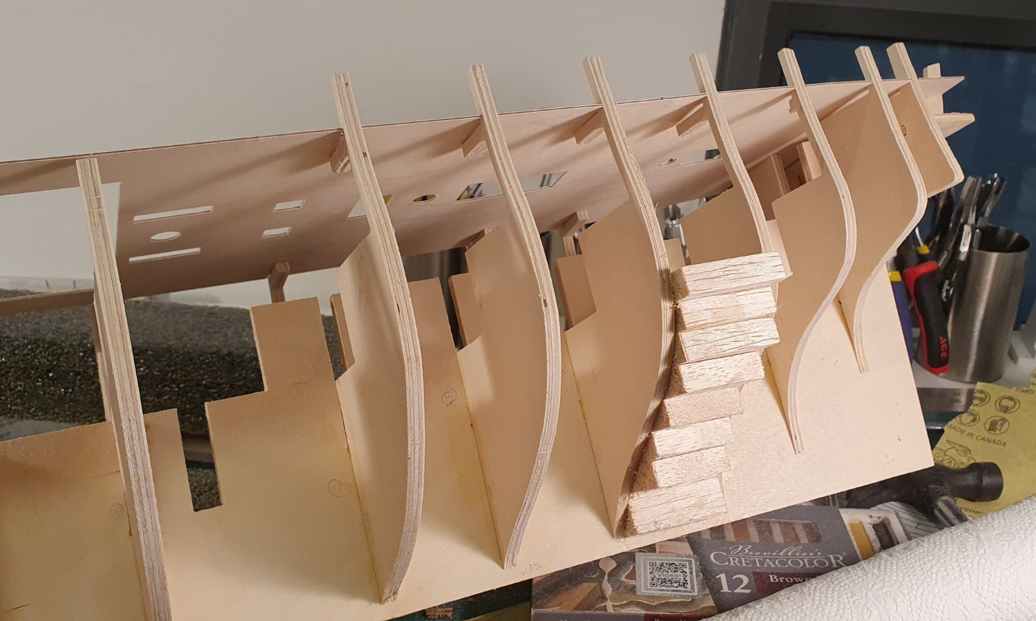
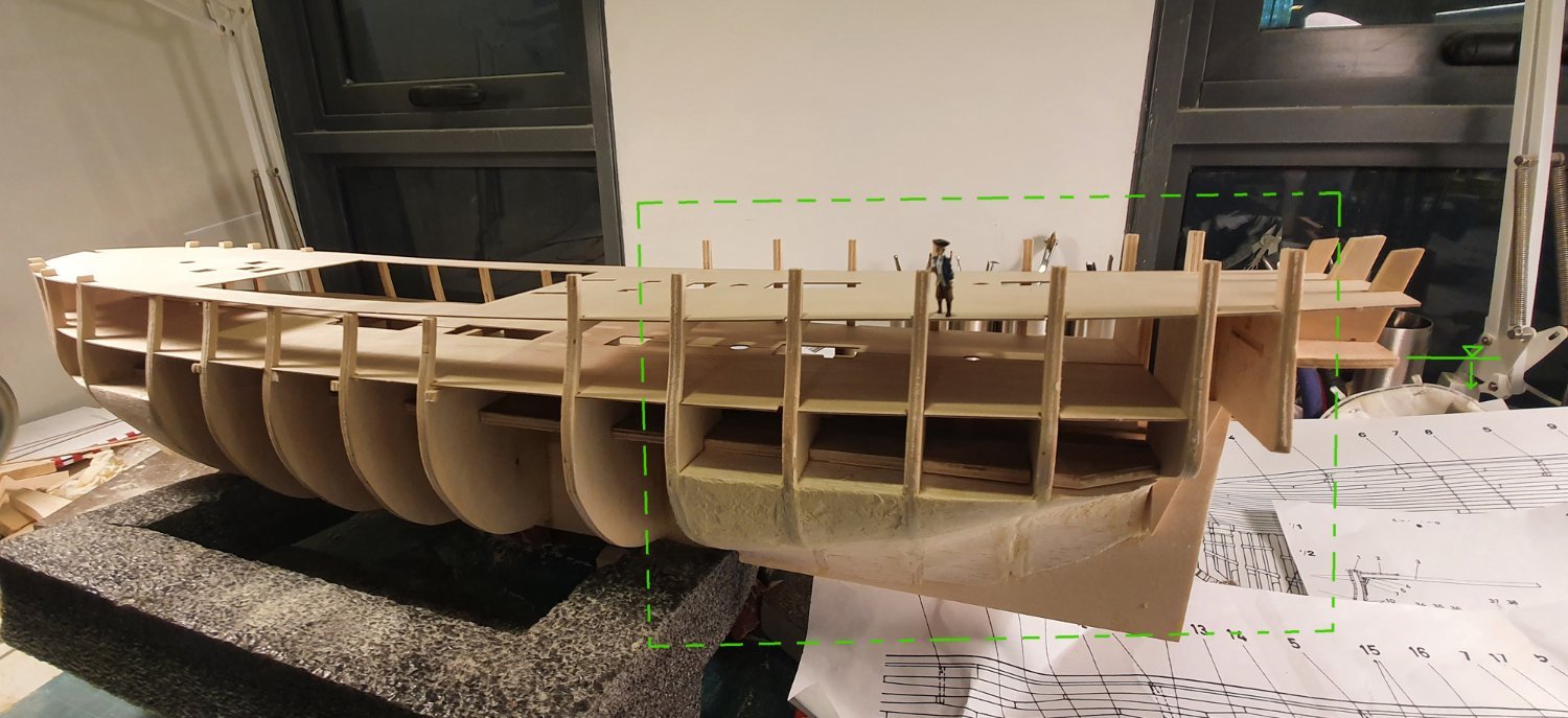
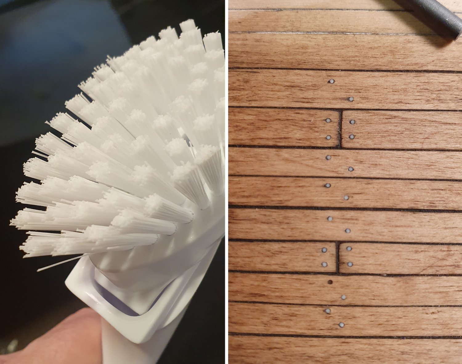
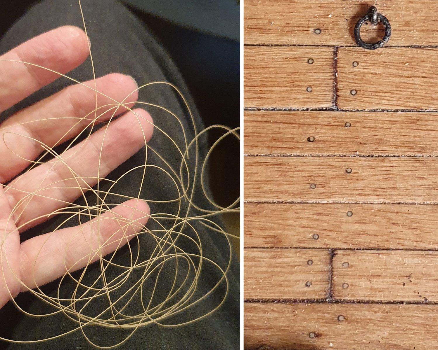
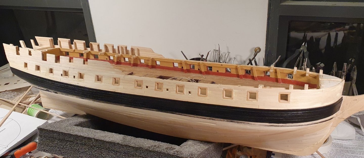
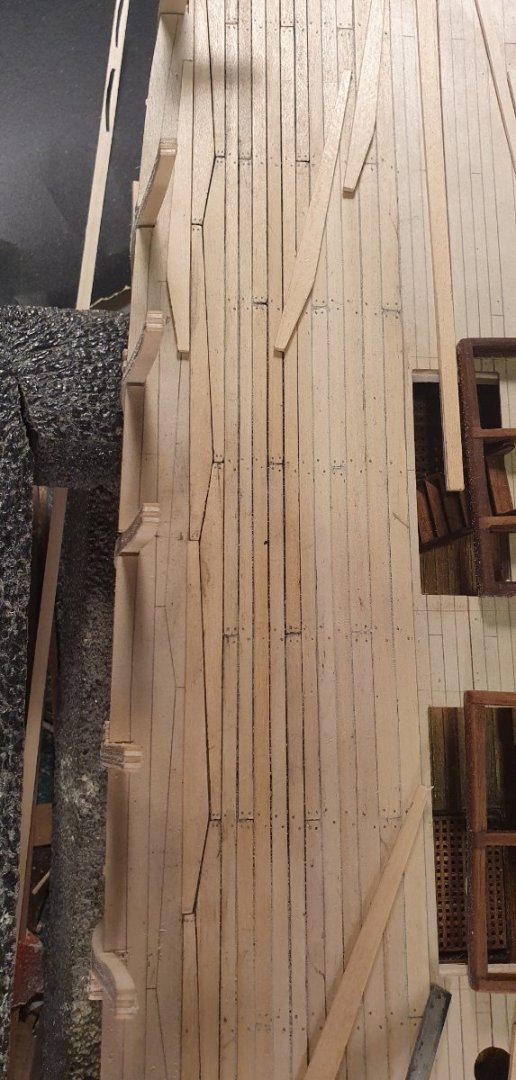
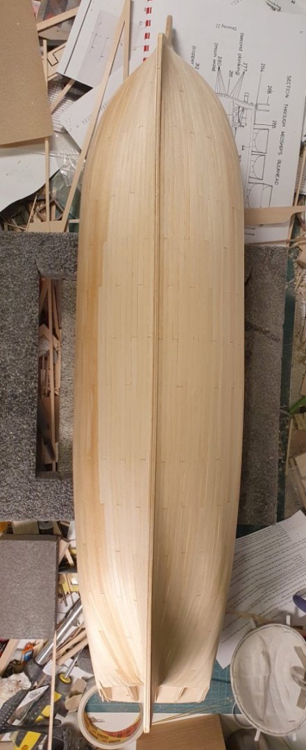
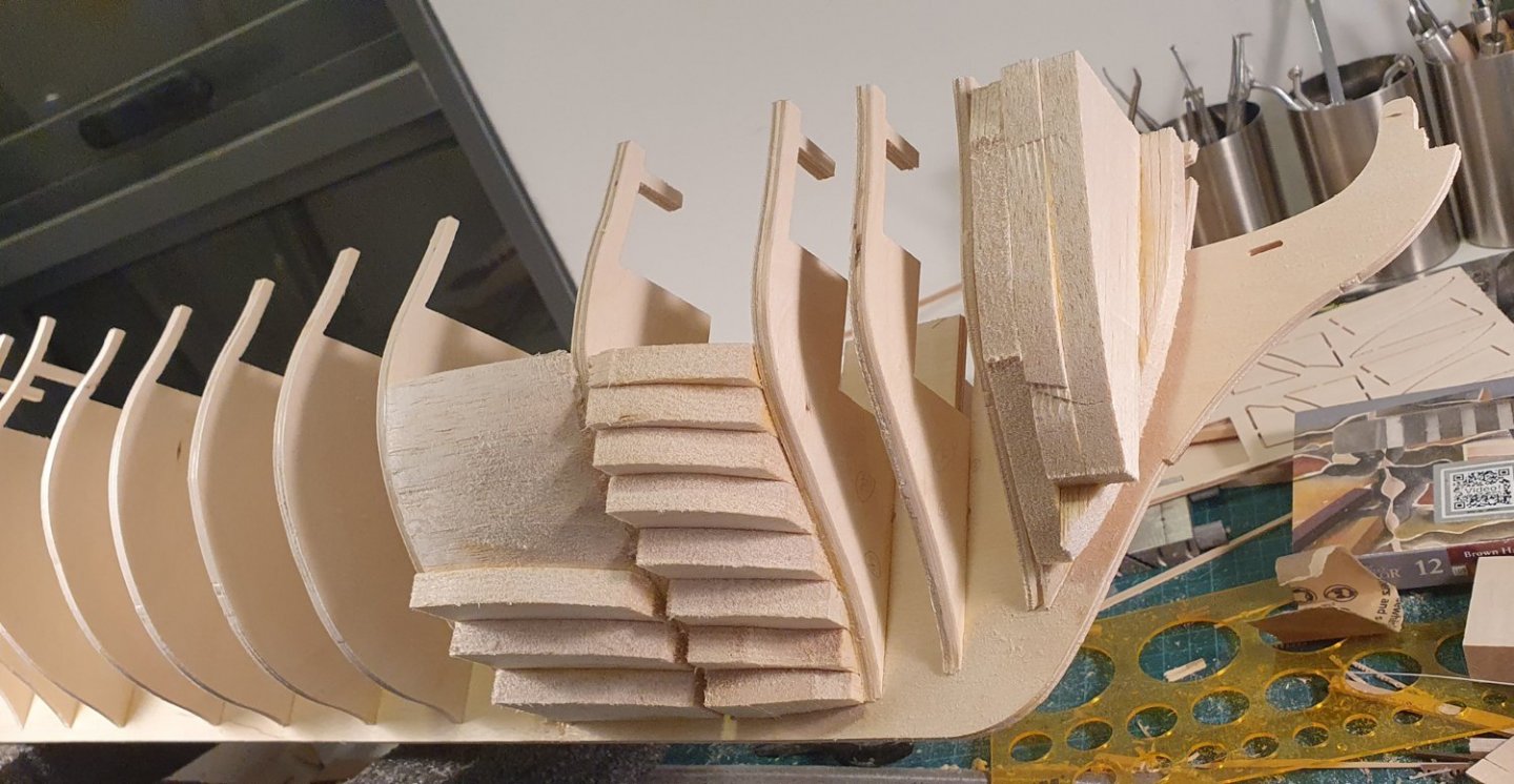
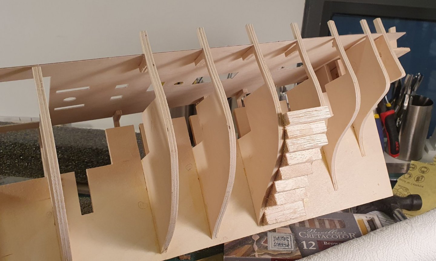
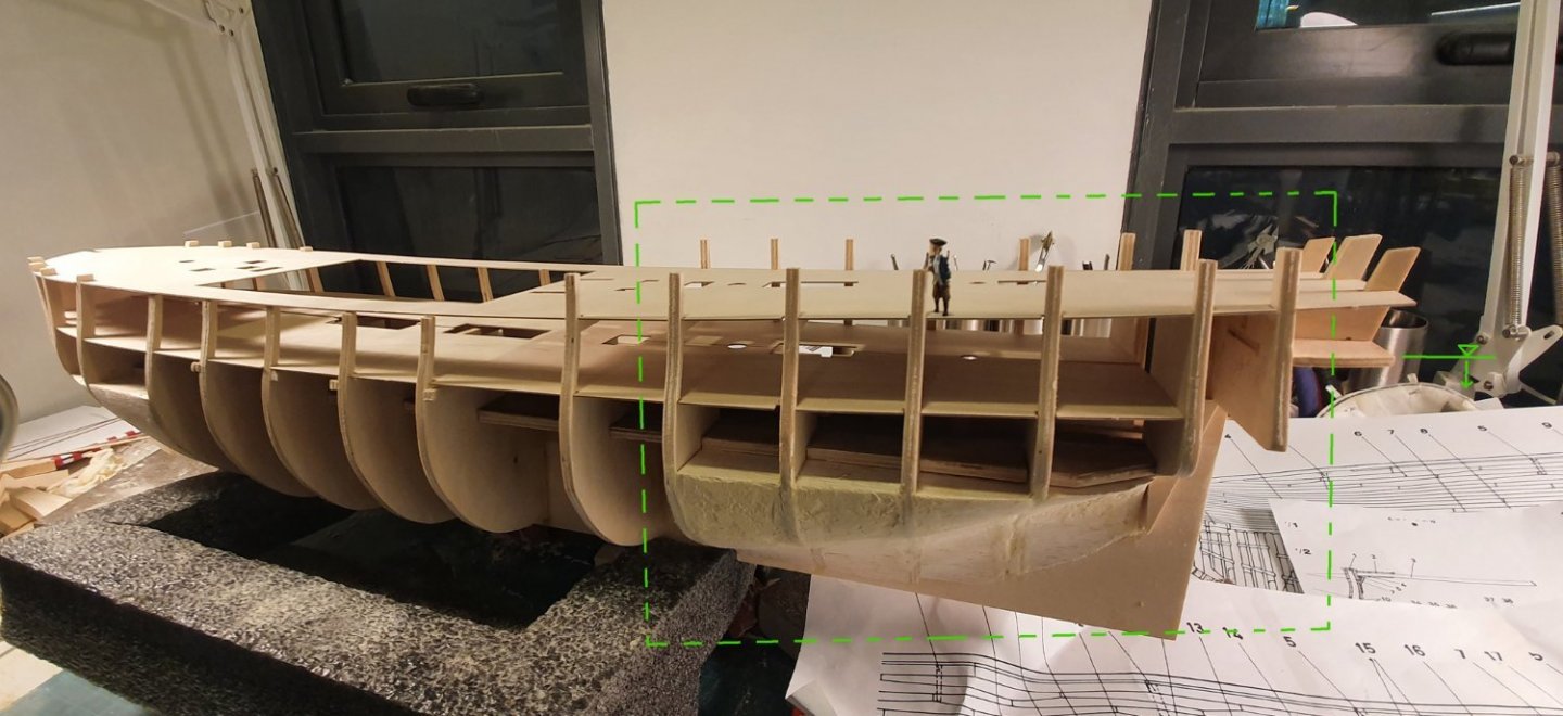
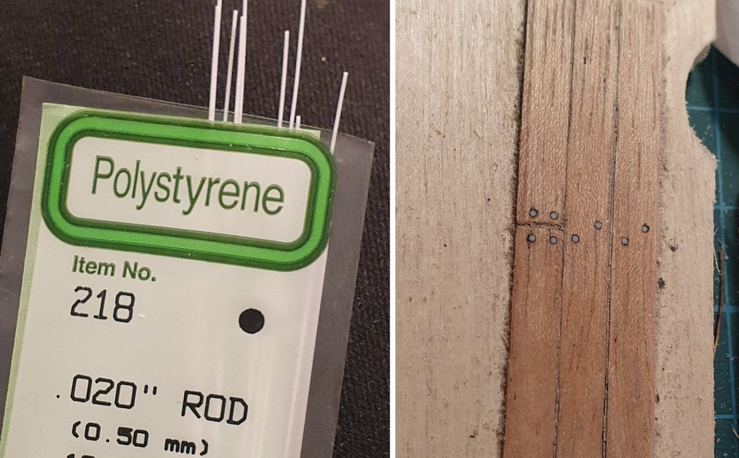
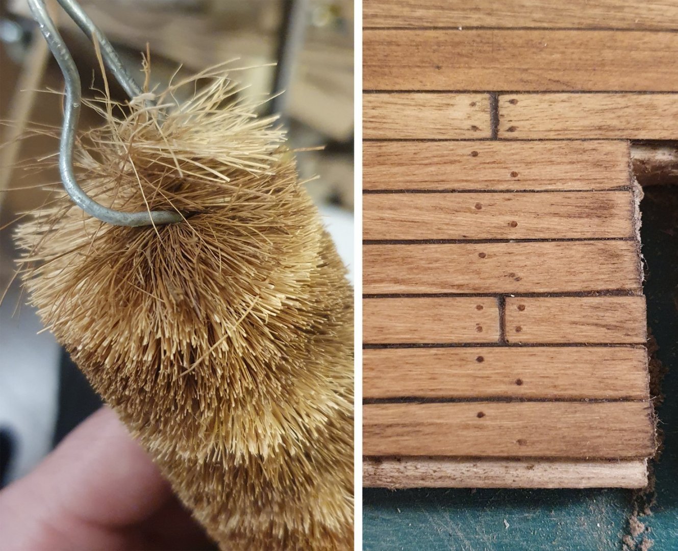
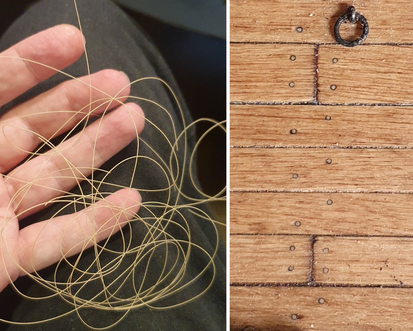
I have decided to attempt a build log. I learn so much from the build logs of other members that I felt that I should venture something in return so, after a gentle prod from Dunnock, here we go. I am fairly new to the hobby having taken it up two years ago. I had just completed the Charles W. Morgan which was very enjoyable and selected the HMS Diana for my next build as it is a very pretty ship. I did hear that the kit itself has issues but thus far it has gone together without too much trauma. I started this build in January 2021 so the first few posts will be a catch up to where I am now. The book The Frigate Diana from the Anatomy of the Ship Series by David White (AOTSD) is a very valuable resource for anyone attempting this build and is my first call for reference having more or less shelved the drawings and instructions. I also reference the drawings of the Artois class ships housed in the National Maritime Museum (NMM) along with photos of their collection of contemporary models and of course the wealth of information contained in the build logs of other members. The basic frame went together fairly easily but I did have to use the heavy file to get the pieces to fit together. I introduced some balsa blocks to fill the bow and stern section as my hull planking skills are a bit shaky and I need as much help as I can get when tackling the complicated curves in these areas. I also sawed off the section at the bow and replaced it with a new piece made out of 5mm thick lime wood as I was not happy with the exposed edge of the ply. I wish I had done the same at the stern post. I suspect that there may be something not quite right in the positioning of the rear deck that forms the lower edge of the counter. Having now completed the build in this area I found that the quarter deck galleries ended up sitting too high. There is a good possibility that this may be a result of my bungling but I have noticed this phenomenon in other builds. If I was starting again I would do a lot more checking of the profiles of the aft bulkheads against the drawings in the AOTSD and the drawings from the NMM. It is only around 4 or 5mm difference but it is quite a difference to what is shown in the NMM drawings. It should be noted that these sit a bit higher in the drawings for the Jason and the Seahorse but these are still lower than where mine ended up. I will just have to live with whatever I have as it is too late to go back and do any modifications. The lowest deck can only be glimpsed through the gun deck hatches so I used this an opportunity to test out some planking mockups. I settled on a maple plank and I tried to give it a more distressed look using various stains and pastels but feel that the end result was a bit dark. I went a touch lighter for the gun deck itself. I am aiming for a more weathered look as I do not possess the mad skills required to produce one if those immaculate looking models and I can always pass off any wonkyness as an intentional depiction of wear and tear. I wanted to add trenails but ran into a bit of bother. I have heard that bamboo skewers can be lathed down to an appropriate trenail size but that proved very time consuming and frustrating and didn't provide a very good result. I think that the skewers are best left for the Kebabs. I then tried some 0.5mm diameter styrene which was good in terms of a consistent shape and size but they were too white and I needed something closer to a 0.3mm diameter. While wandering about the supermarket I found a scrubbing brush that had bristles that were 0.35mm diameter which was an improvement on the styrene but still too white. I then went back to the supermarket and found a brush, which I assume is for cleaning bottles, that had natural bristles that were a better colour and the correct diameter if you could be bothered sifting through them. Despite the fact that they are too dark and painful to work with I ploughed ahead and completed half the gun deck before I discovered that I could get excellent trenail material if I ran the faux wood filament through the 0.3mm diameter nozzle on my 3d printer without printing anything. It is the correct size and dimension and they almost become invisible depending of the angle of viewing much like the real thing. They are a little light but it is as good as I can do. As this is my first post I will stop here and submit as I am not that confident of success.


-
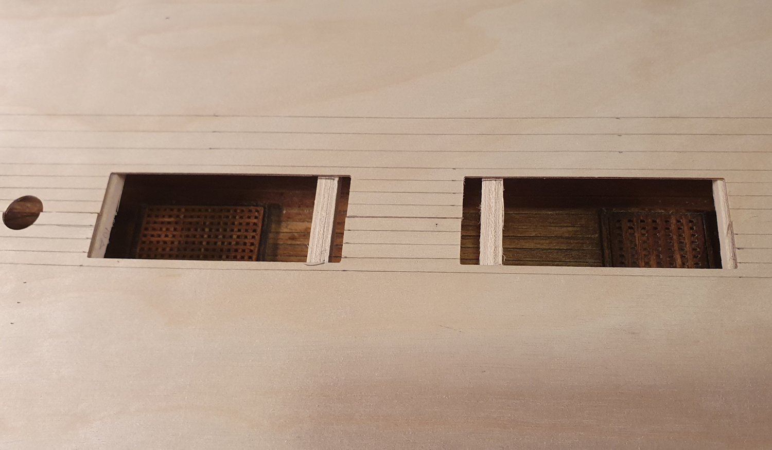
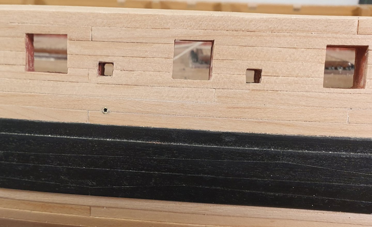
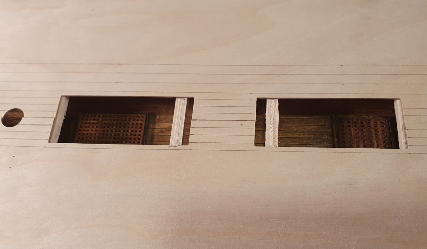
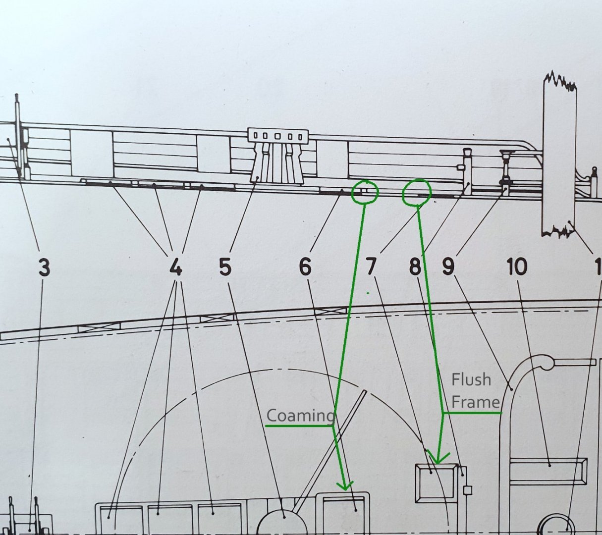
Hi David, I do not wish to hijack your log with more scuttle speculation but I am currently building a Diana and I am following your build with great interest. I have been looking closely at these openings and I believe that the AOTS drawings are correct albeit lacking in granular detail. The sectional drawing shows the scuttles flush without coamings as highlighted below and the double line around the scuttles with the mitred corners shown on the plans represents the flush frame of the hatch cover. This can be seen in the below photo of the same scuttle cover on the HMS Trincomalee (admittedly built 22 years later). I guess whatever way you go it is the modeler's perogative. Good luck, David

- 310 replies
-
- 2
-

-
- Diana
- Caldercraft
- (and 1 more)