HOLIDAY DONATION DRIVE - SUPPORT MSW - DO YOUR PART TO KEEP THIS GREAT FORUM GOING! (Only 13 donations so far - C'mon guys!)
×


DavidEN
-
Posts
136 -
Joined
-
Last visited
Content Type
Profiles
Forums
Gallery
Events
Everything posted by DavidEN
-
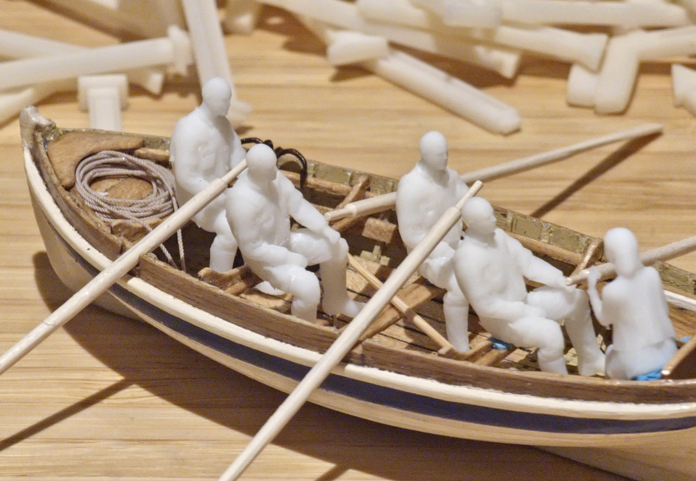
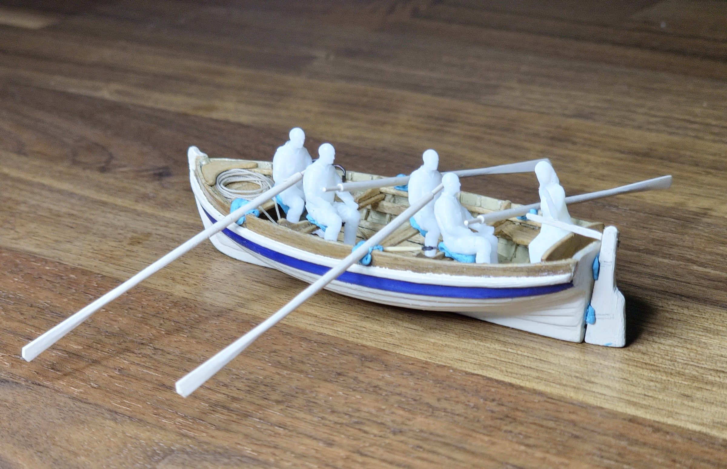
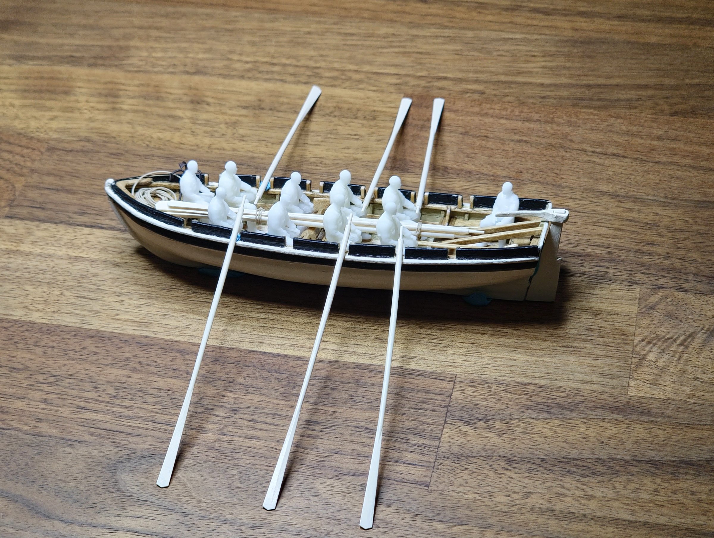
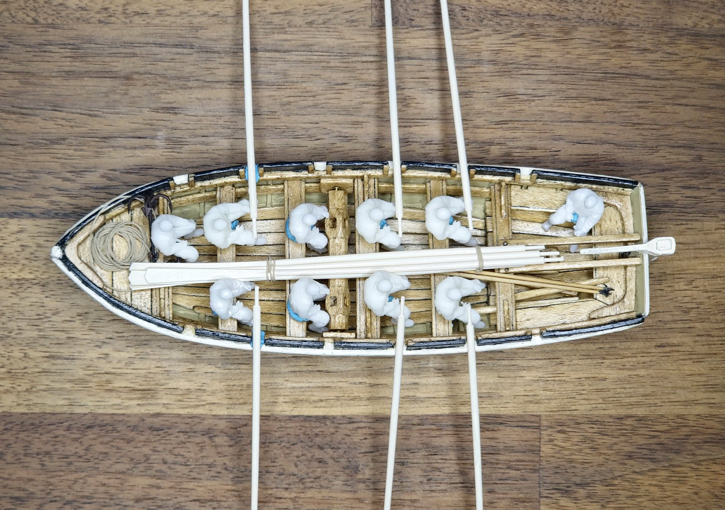
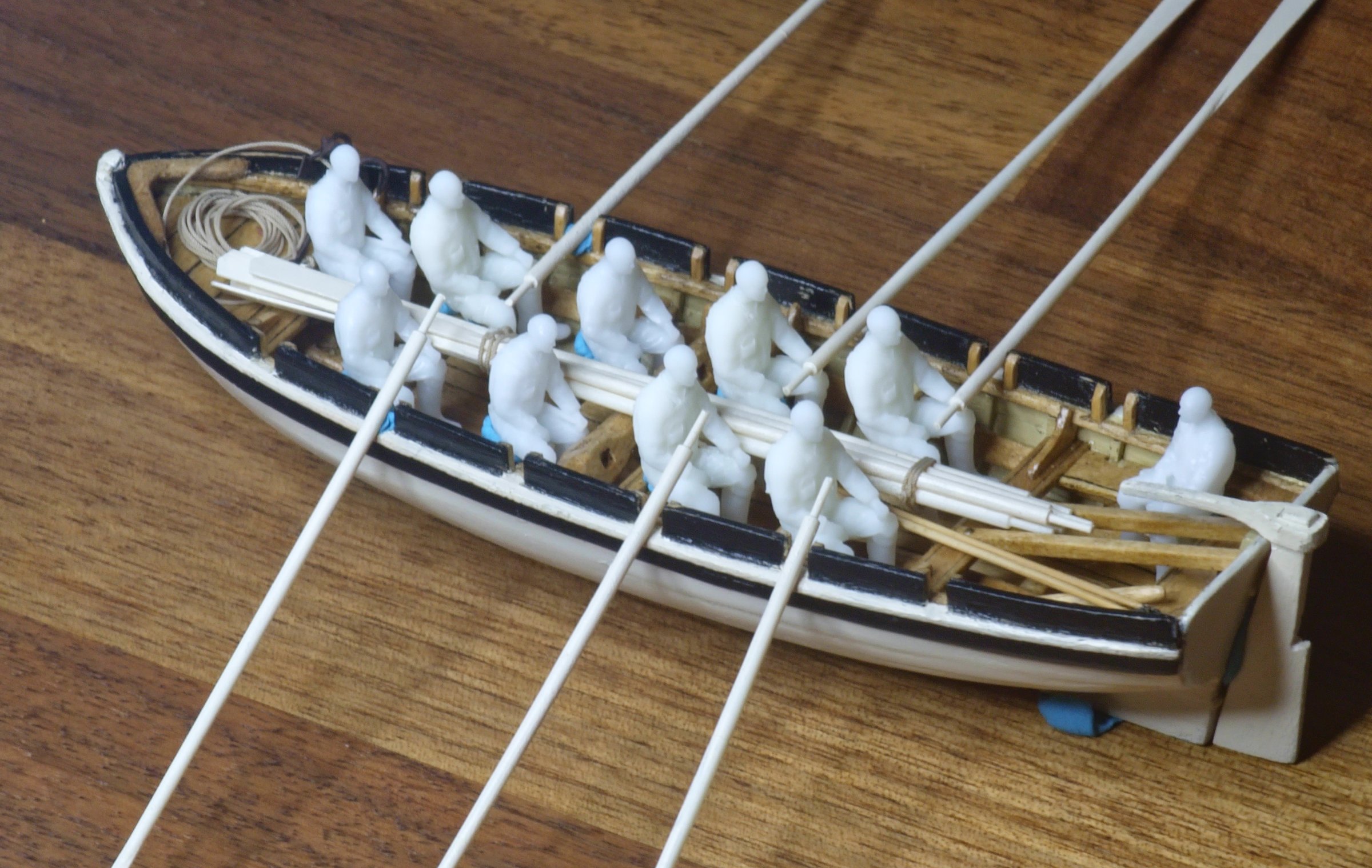
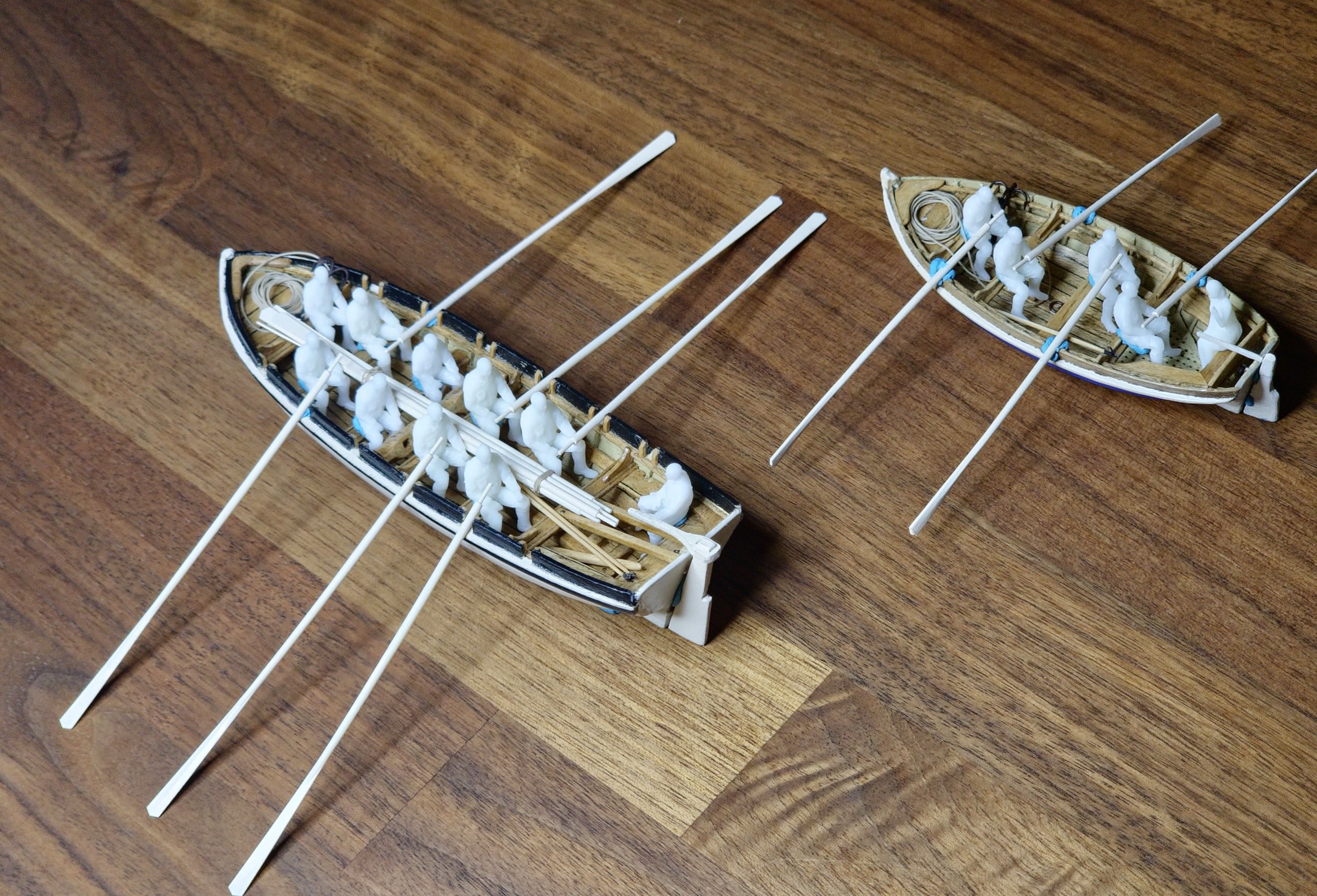
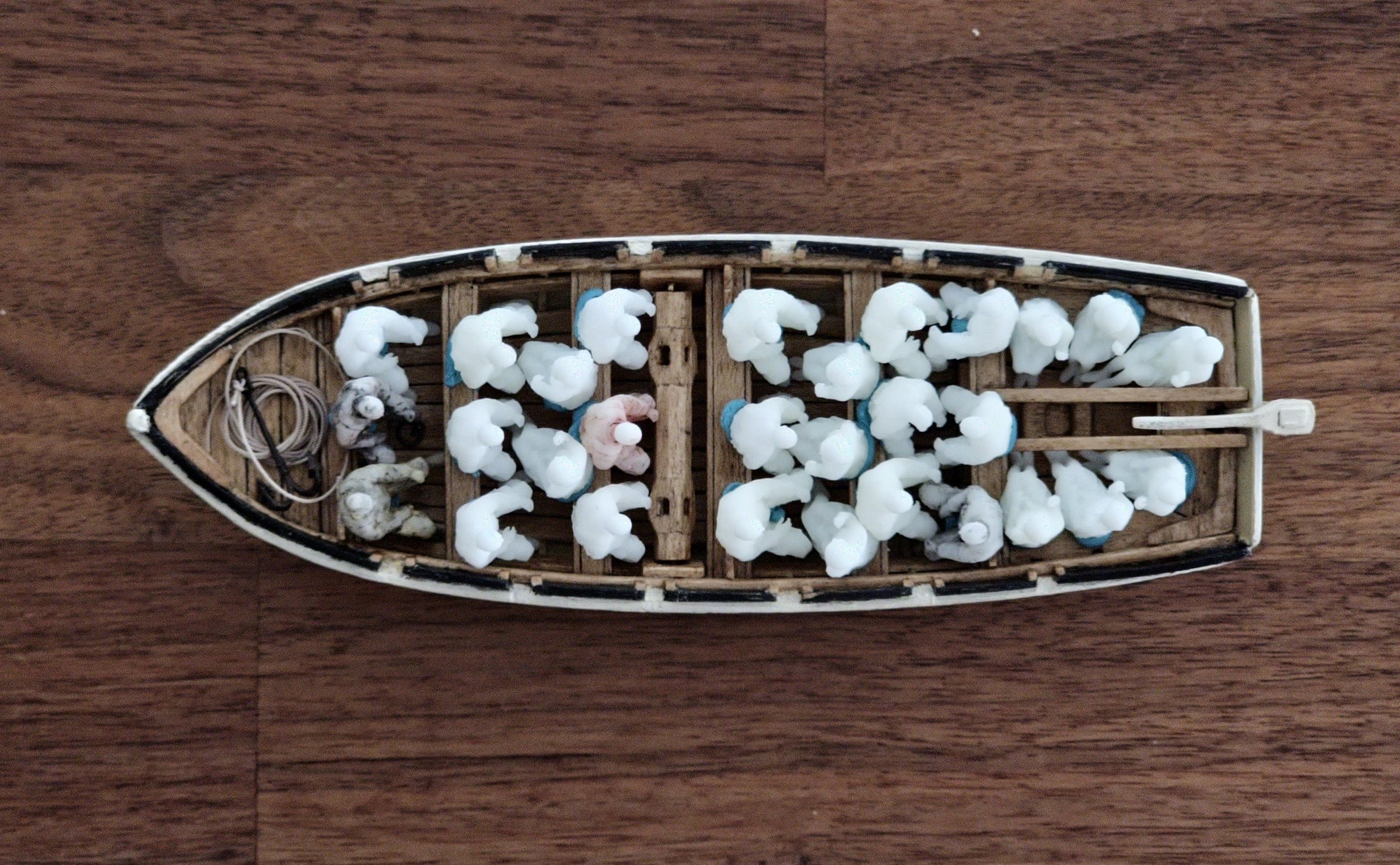
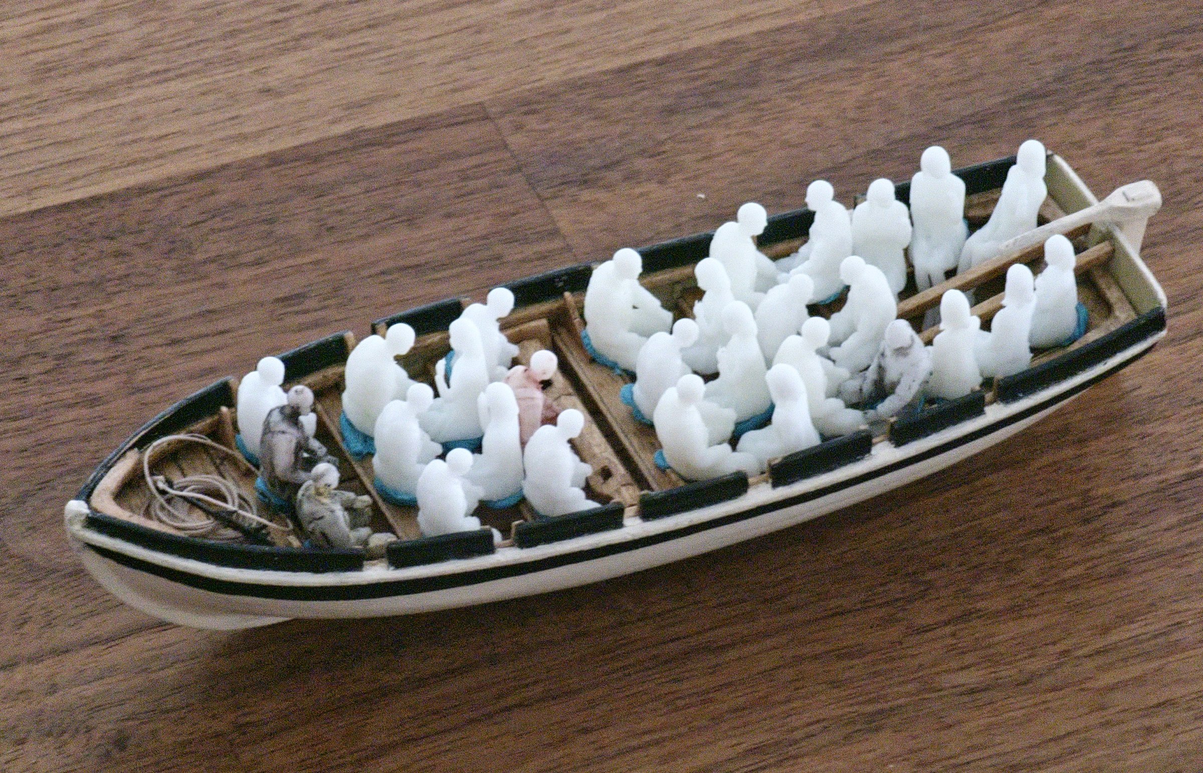
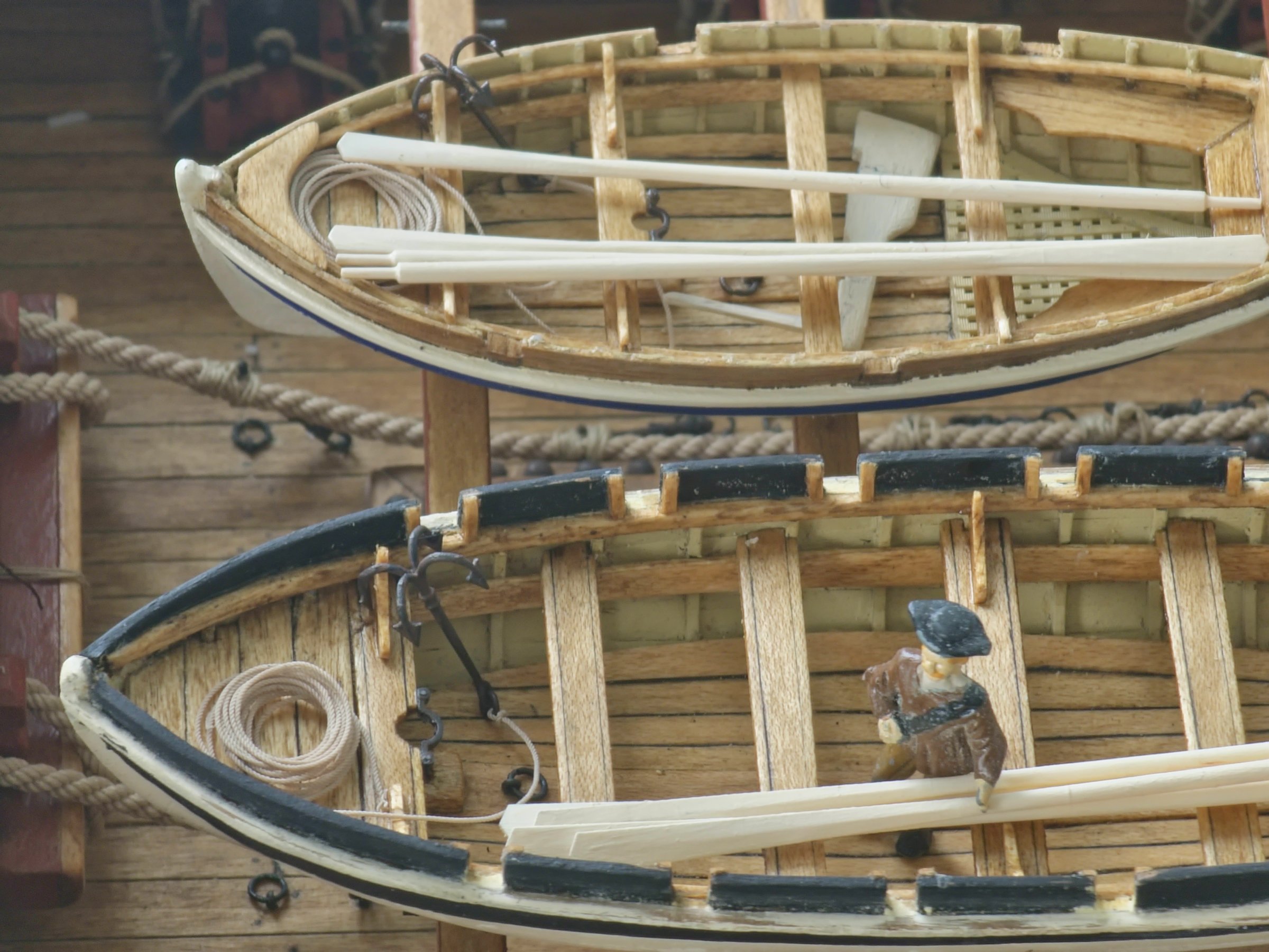
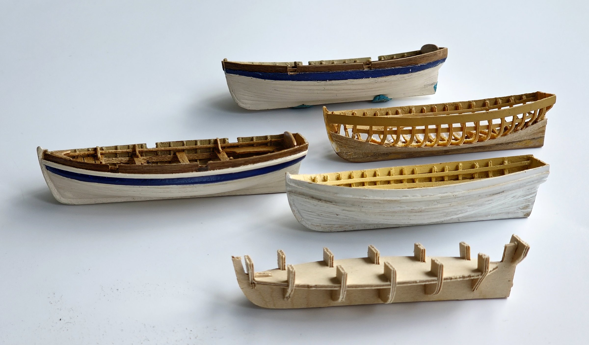
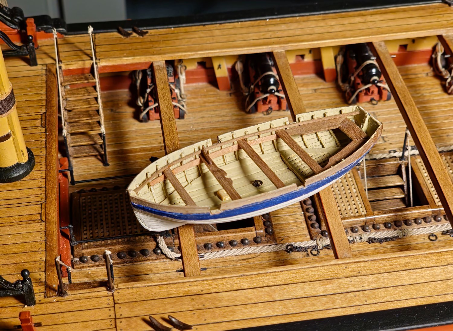
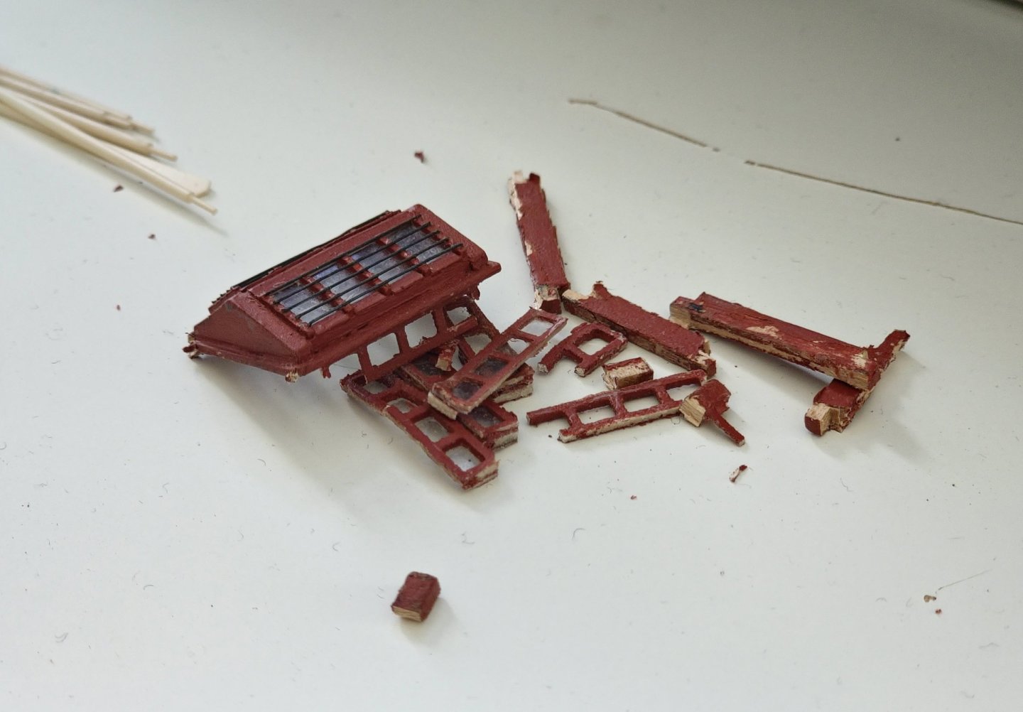
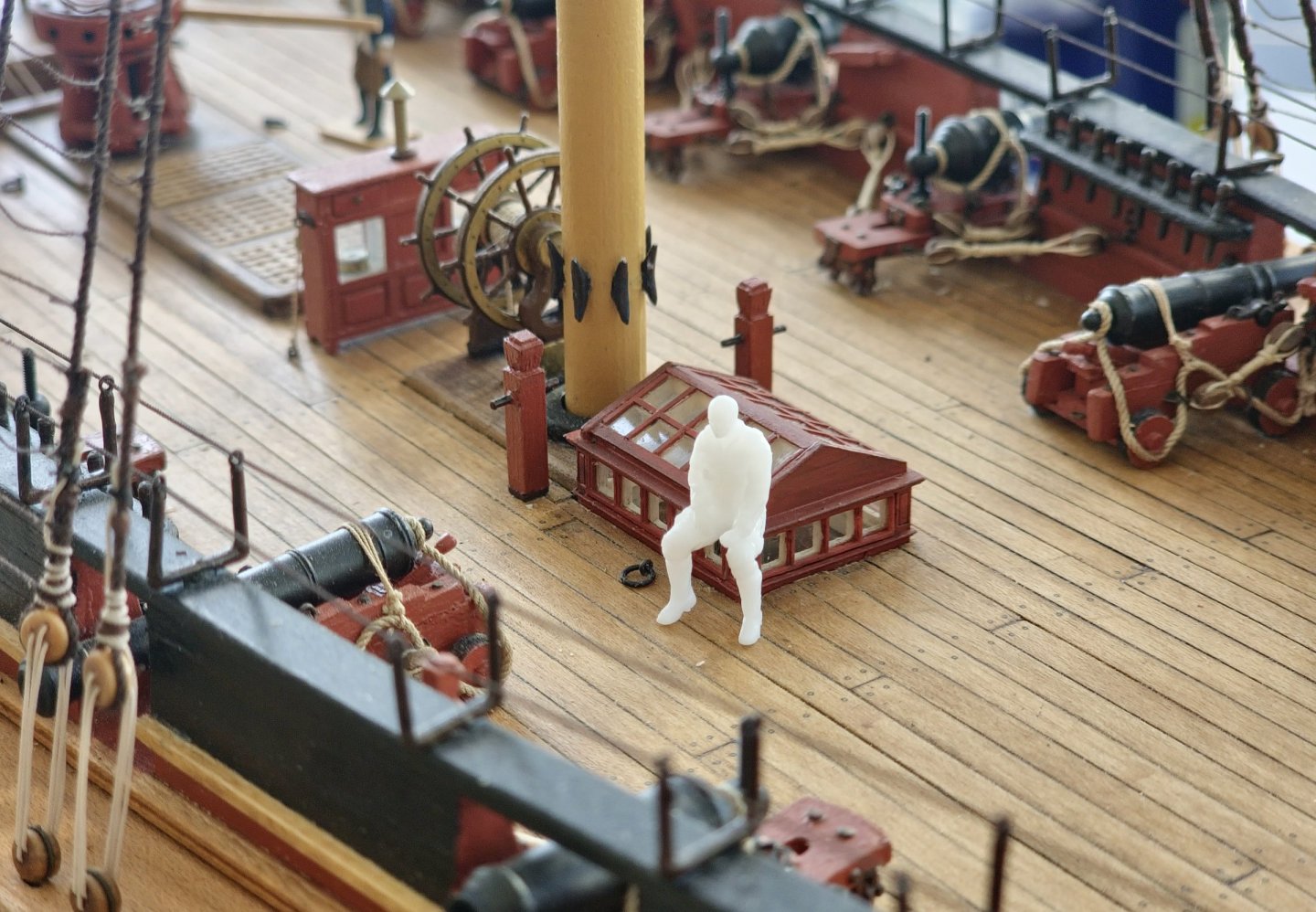
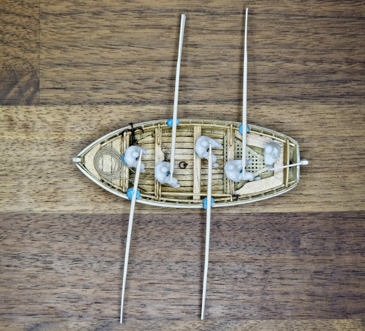
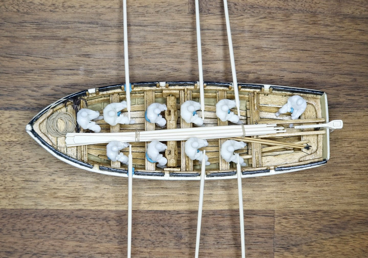
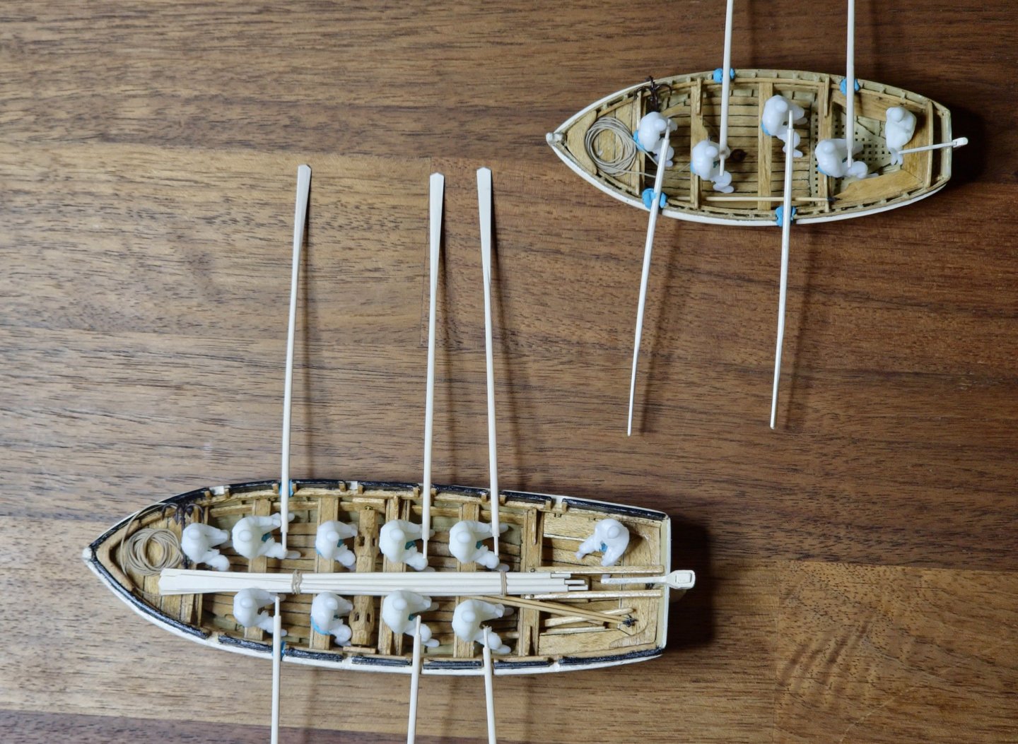
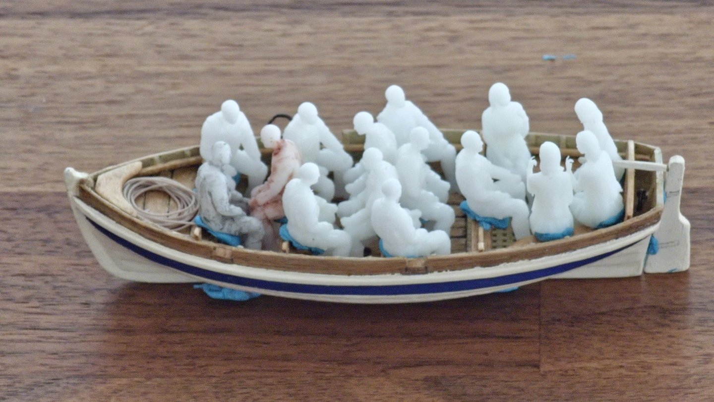
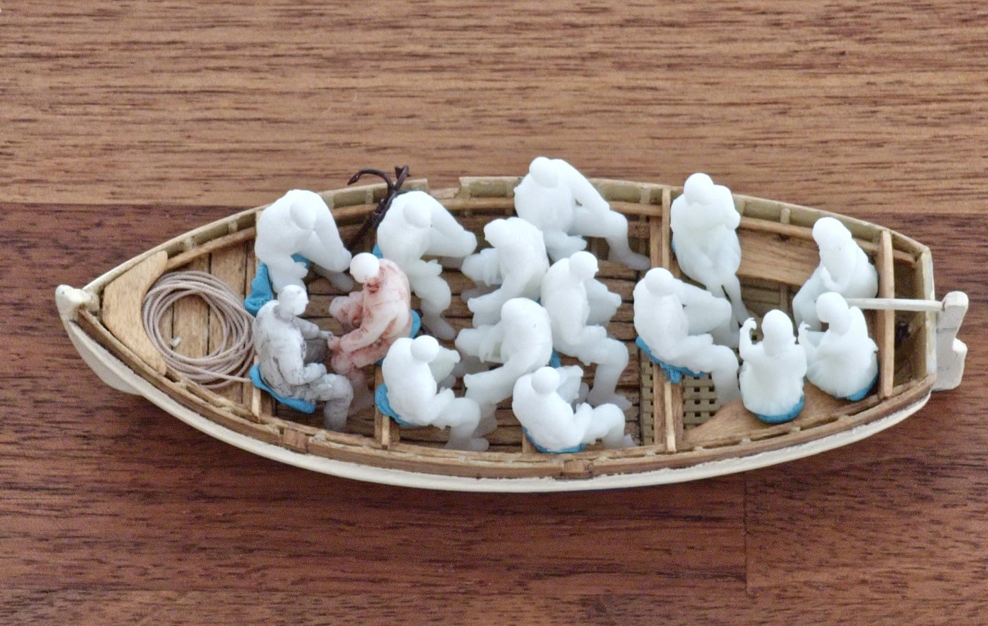
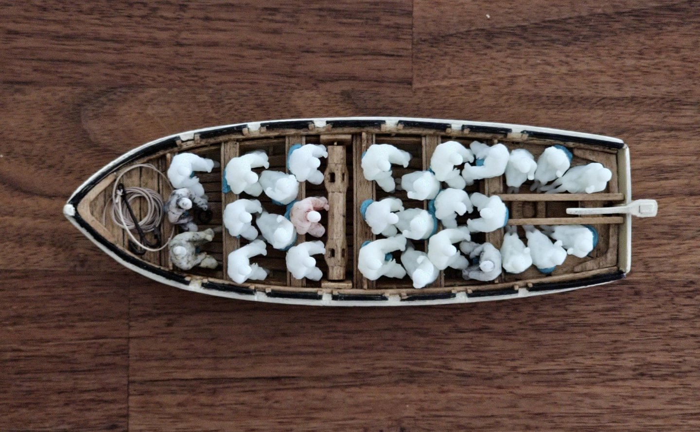
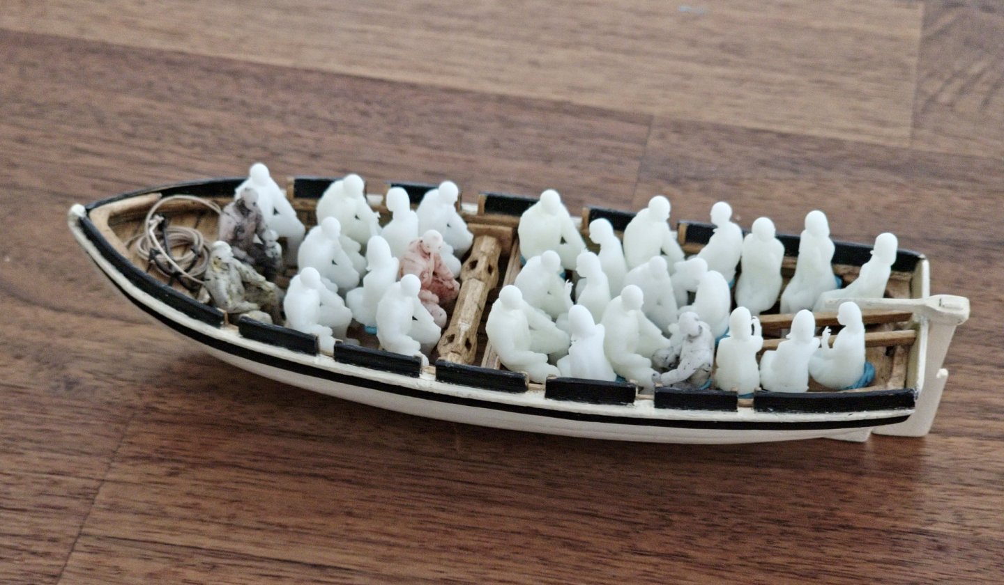
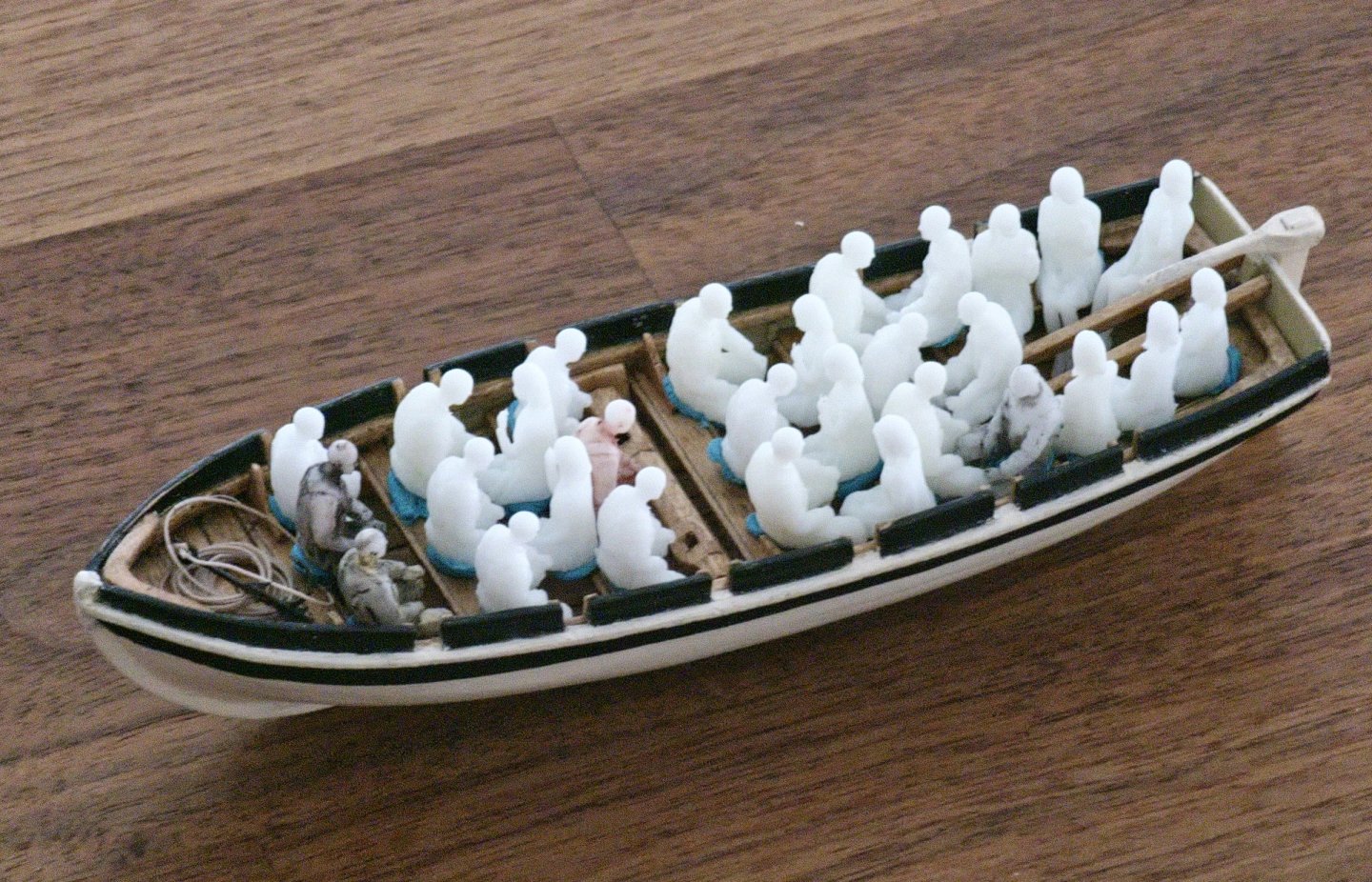
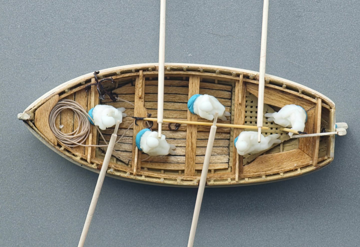
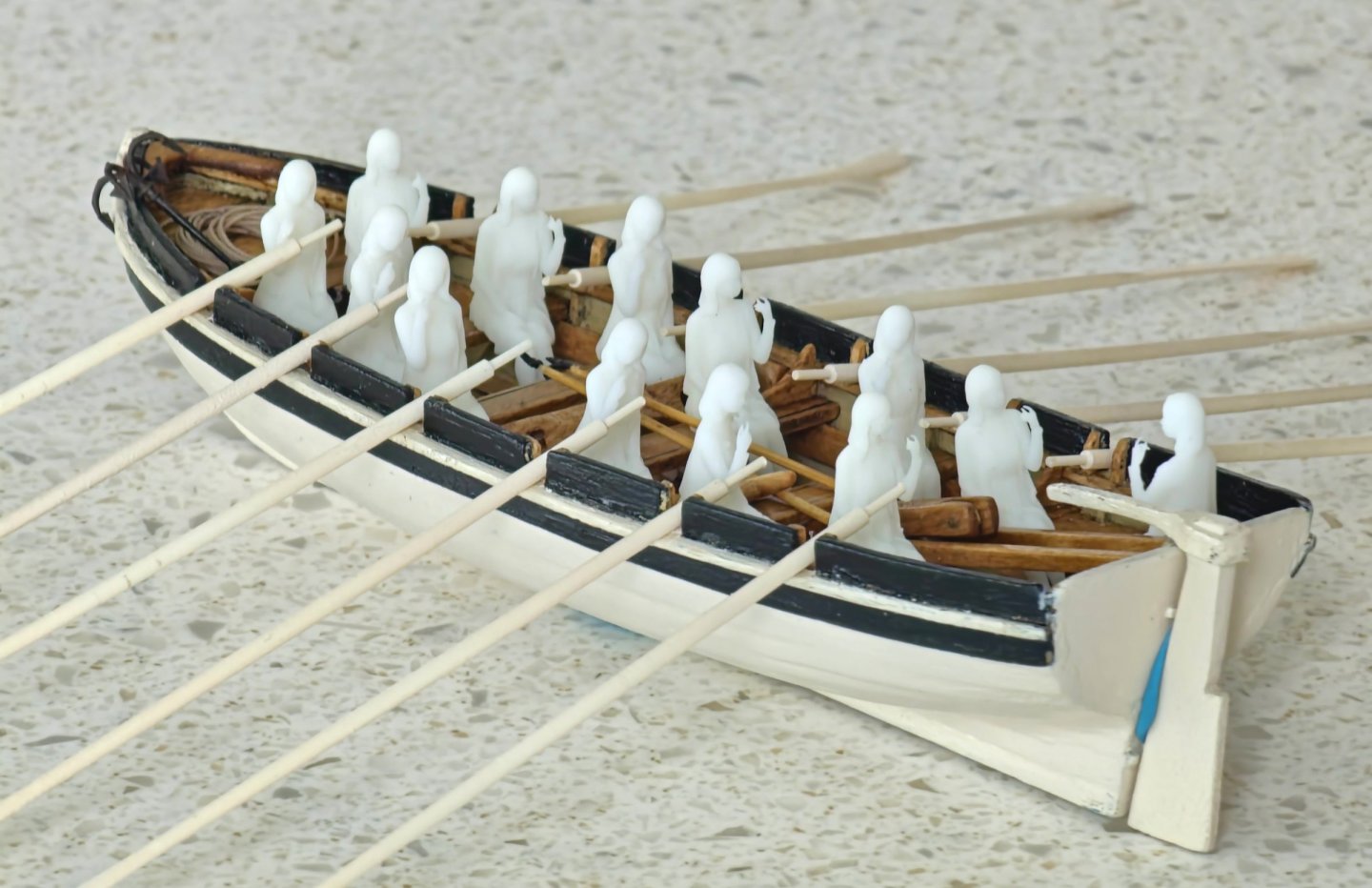
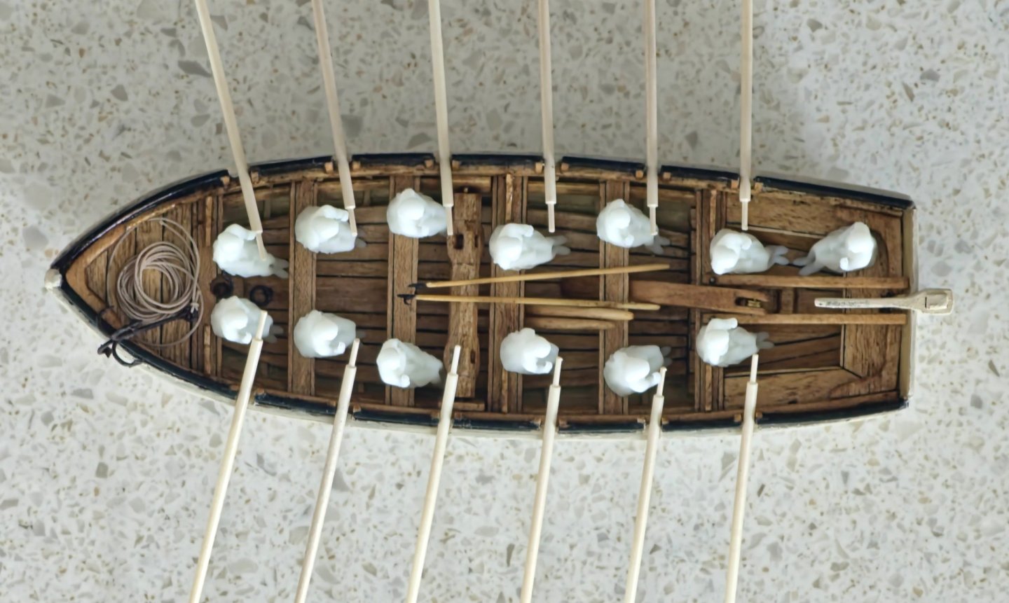
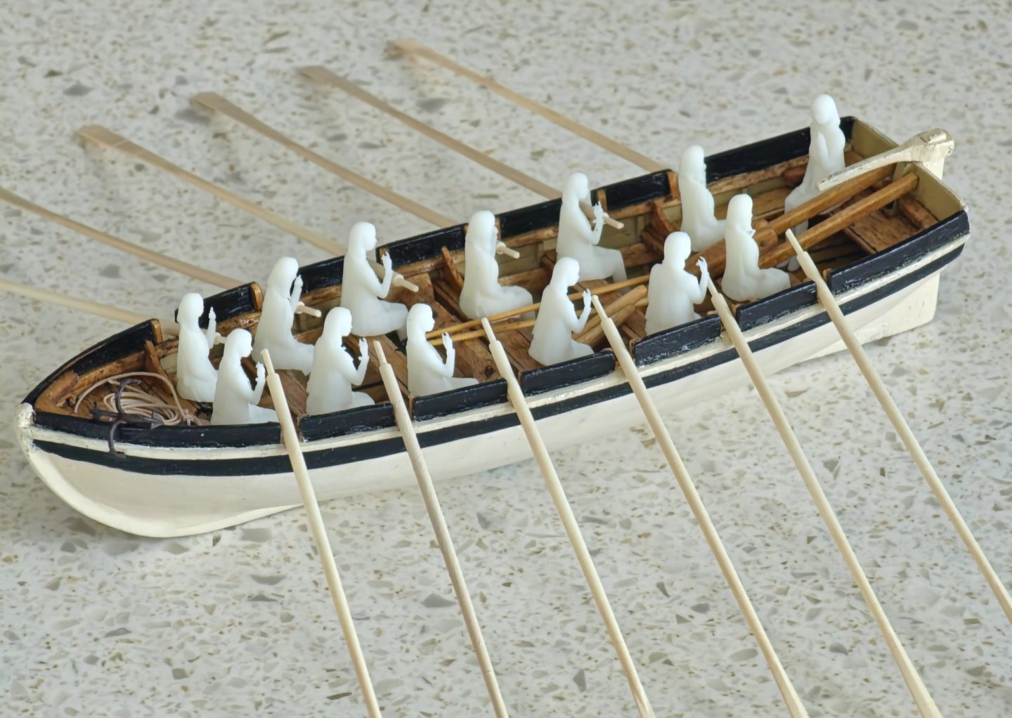
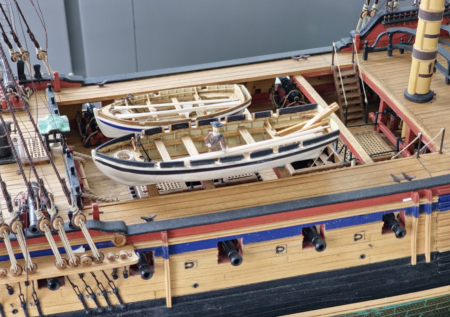
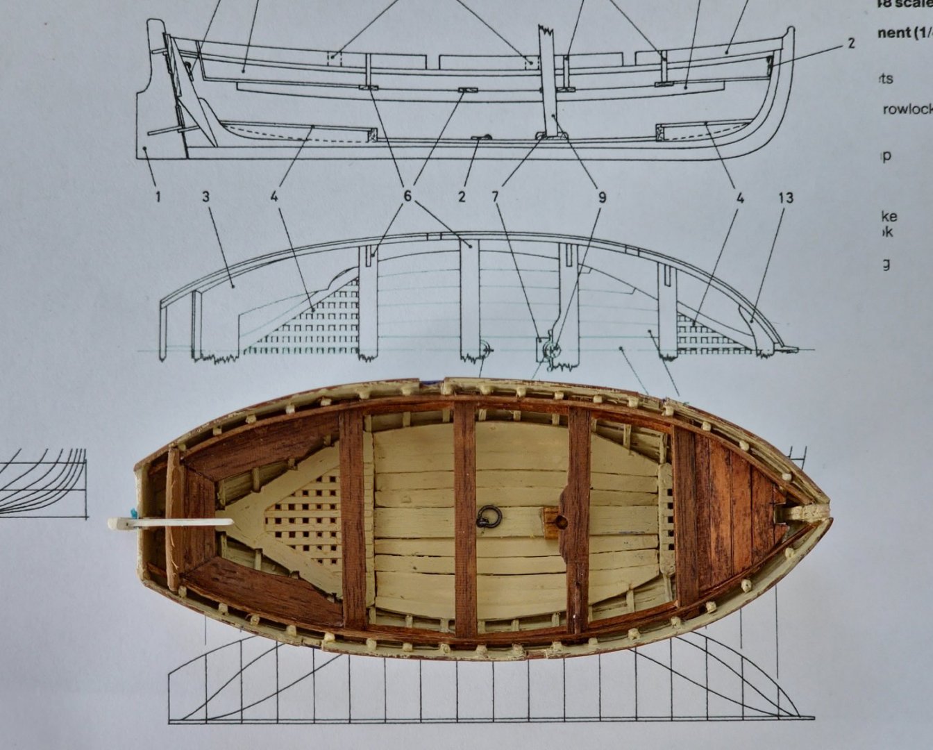
Gosh! It has been a while since my last post. All work ground to a halt while I did other things and the ship just sat there gathering dust. Once you stop pedalling on a hill it is hard to overcome inertia to get going again. It was such a long time that I even forgot my password to this site and could no longer log on. I decided that I need to pull myself together and make a push for the finish line. I thought that I should start with some gentle tasks to get me back into the swing of things so I took the opportunity to swap out the companion with the new 3D printed one I made a while back. I was not altogether convinced by it but I thought that I would see how it looked in place. The old one was well glued and I had to resort to the heavy pliers to get it out albeit in many pieces. I shoved the new one in to the accompaniment of ominous cracking sounds emanating from the deck planking. Seeing that the old one is now kindling I will have to live with the new one. I managed to secure some more manly 3D models of seated figures to test out the small boat dimensions. These are not period figures. I think they are some sort of oil rig workers. With their greater bulk and manspreading they really fill up the boat a lot more than the fashionable ladies. I gave them a quick measure and found out that they are over 6ft tall. Google tells us that the average height for an 18th century seaman was around 5'6" so I scaled down a batch and now the boats look less like a clown car. 18 ft Cutter (Jolly Boat) 26 ft Launch I started up on the final two ship boats namely the 24 foot cutter and the 32 foot pinnace and am in the hull planking phase. I have not progressed very far on these but I am easing myself back into the building routine. It is amazing how much I have forgotten in the last year. Luckily this site is quite a useful tool as an aide-memoire but I am still puzzled as to how I did things the first time around. The thought of all of those tiny planks was giving me the fear so I thought that I would procrastinate some more. Coincidentally I had just been reading the narrative of the wreck of the Medusa and was astonished to see that they managed to fit 42 persons in a 14 oar boat which is presumably a 30ft cutter or launch. They also had 15 persons in a small boat which is possibly equivalent to a Jolly Boat, though the author does refer it to a pirogue later on in the manuscript so it may be a lot smaller and narrower than a Jolly Boat. I guess snugness is a relative term. I tried 15 folk in the 18ft Jolly Boat and they just about fit and I managed to get 29 people in the 26ft Launch. If I were to remove the windlass and increase the length of the boat to accommodate an extra thwart I imagine you could just about get 42 people in.


-
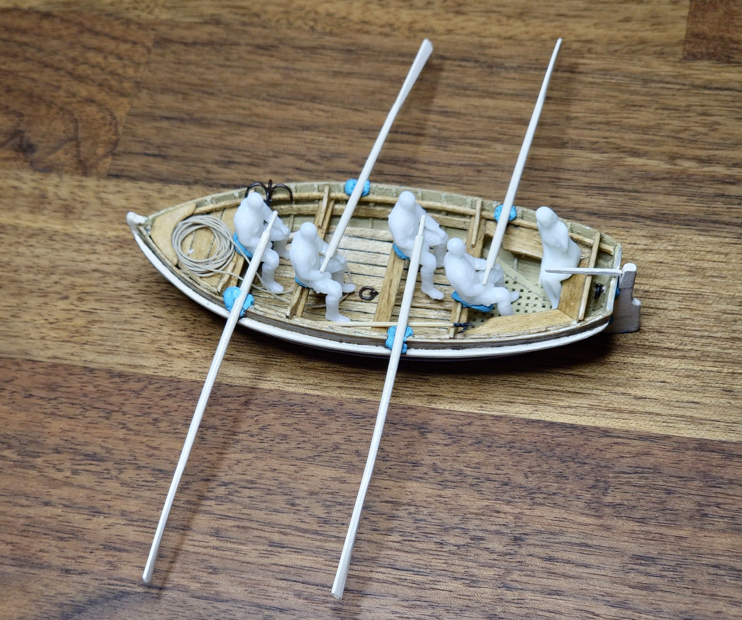
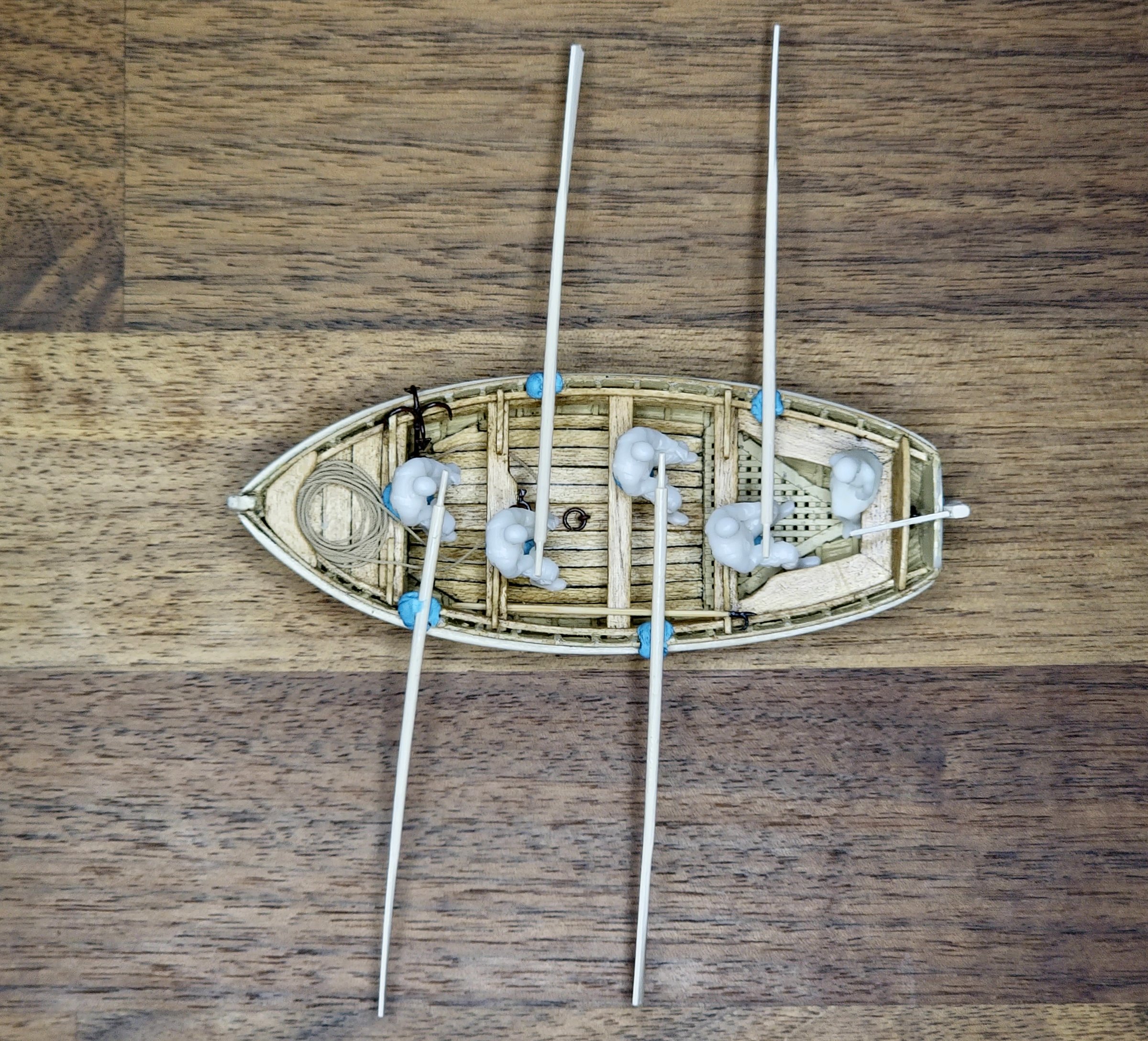
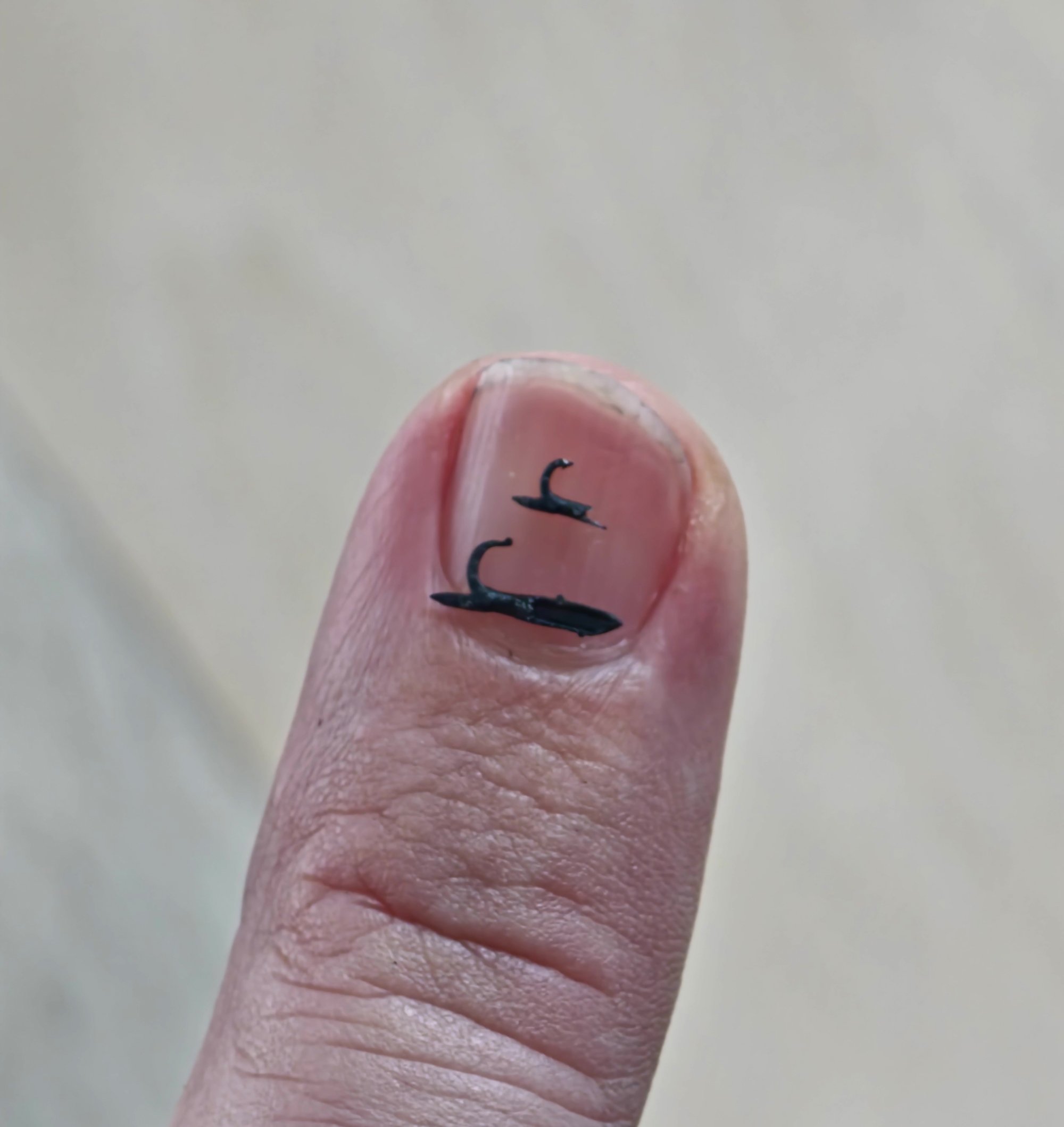
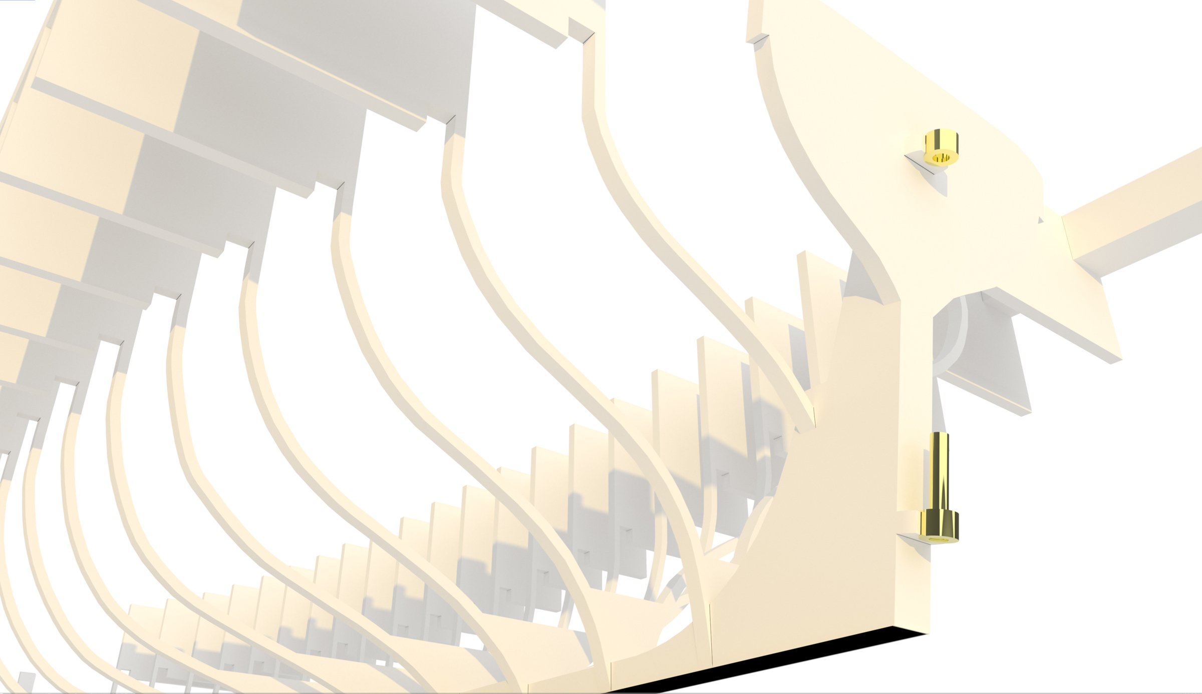
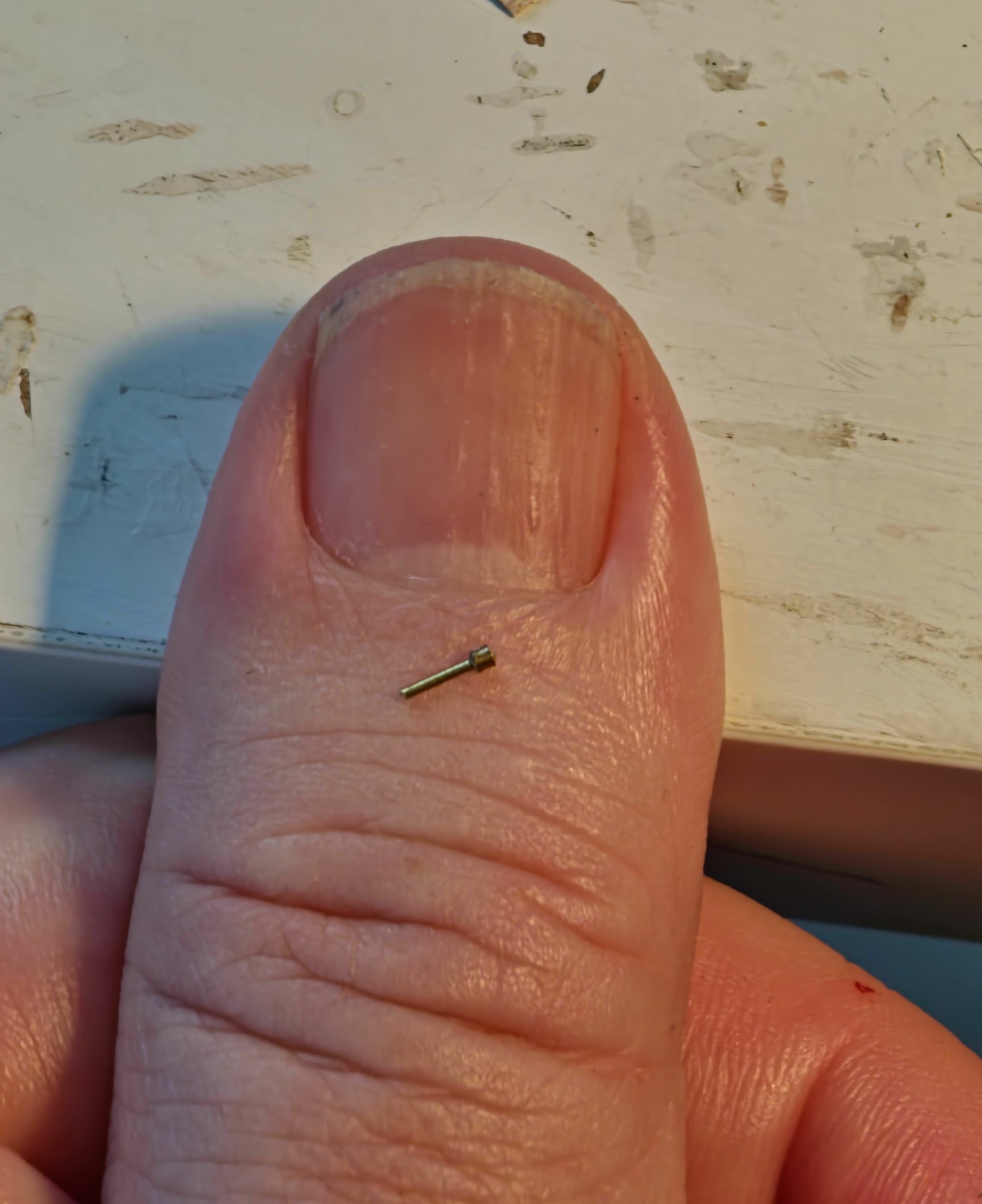
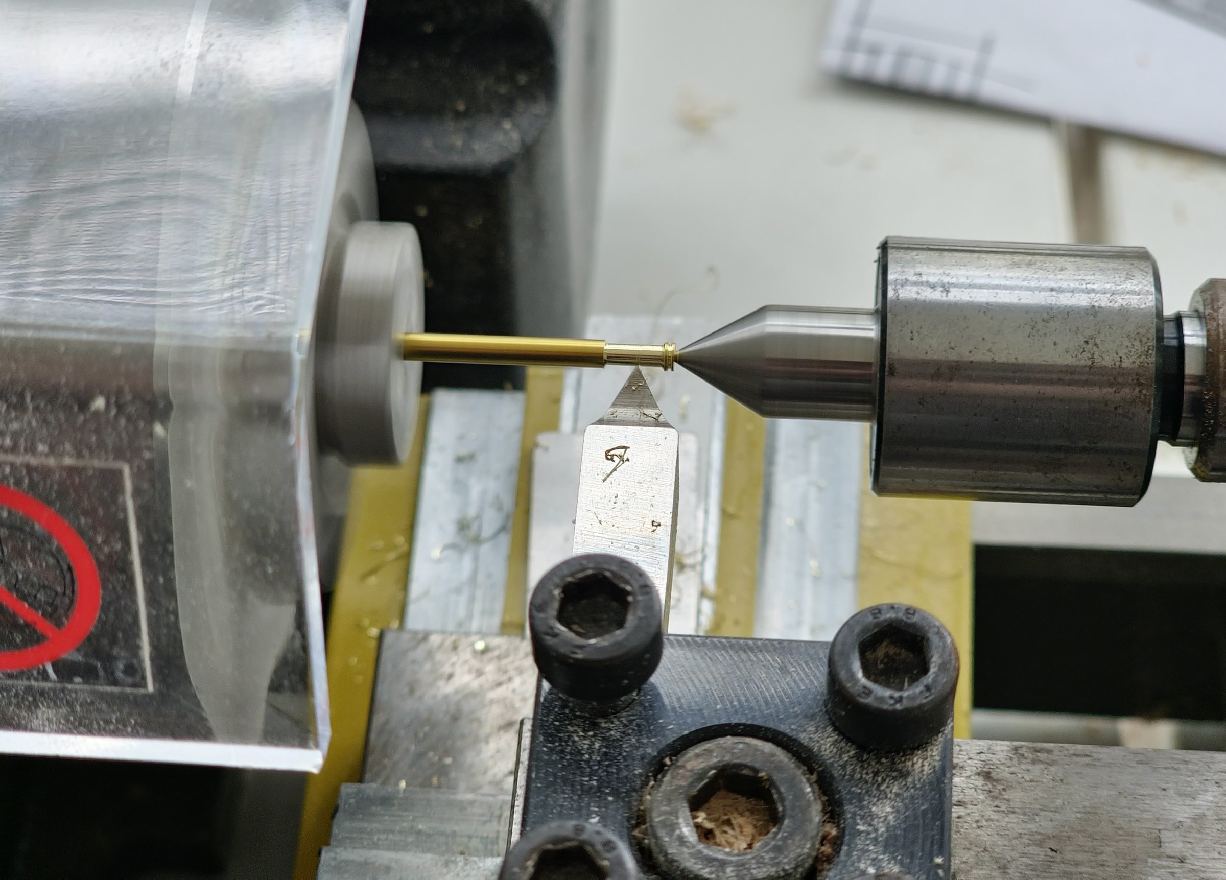
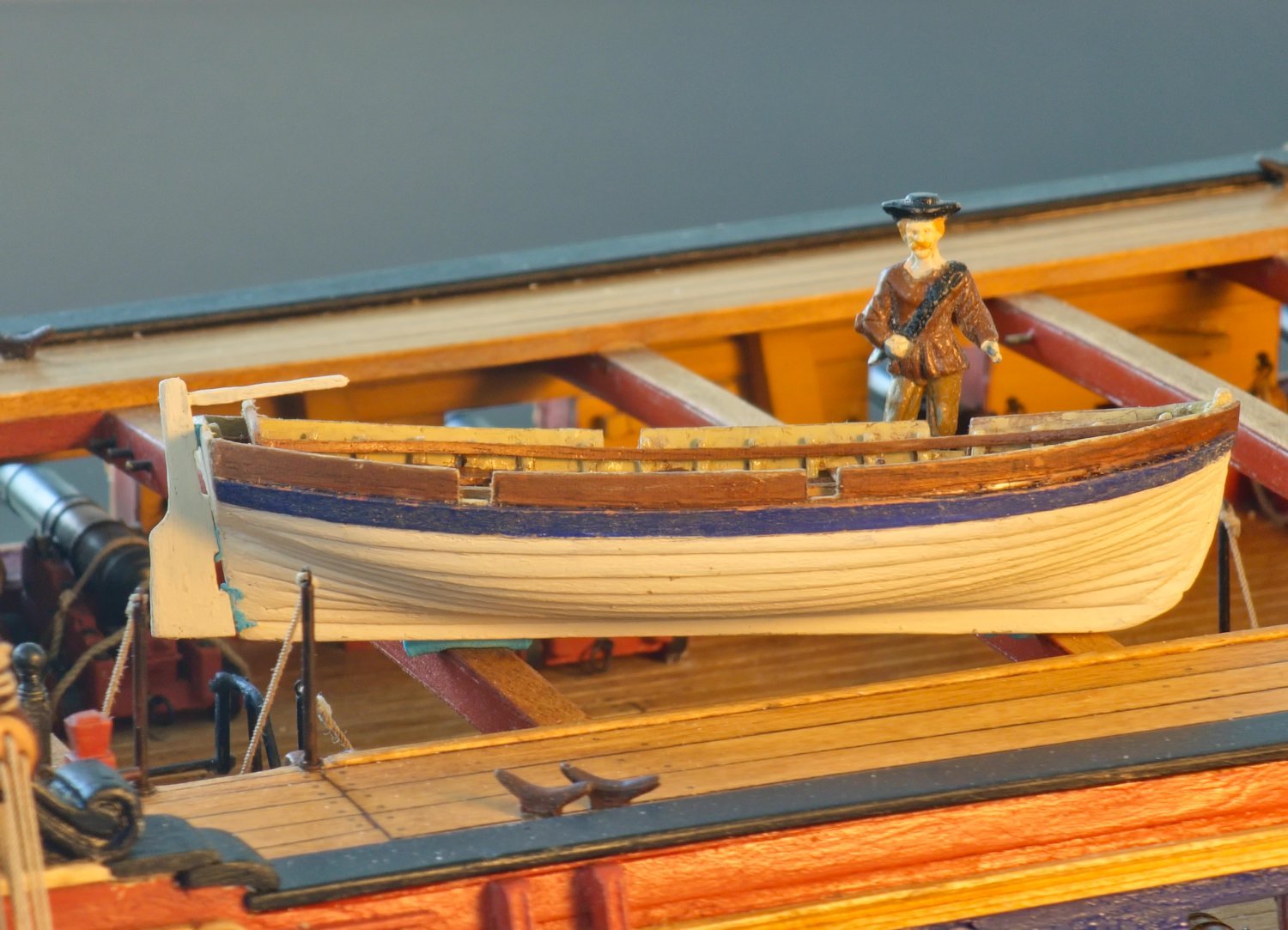
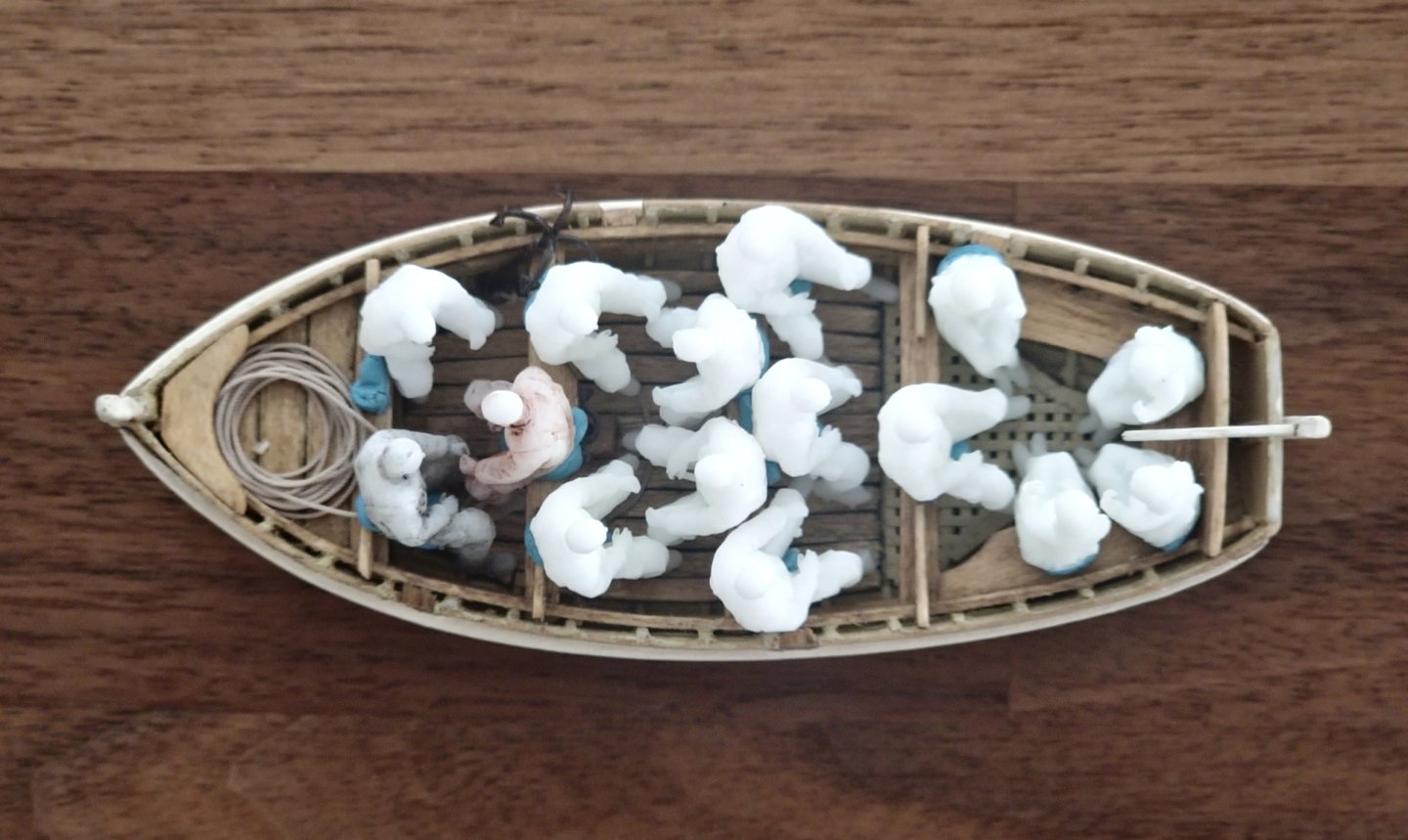
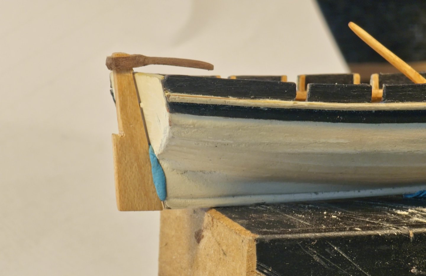
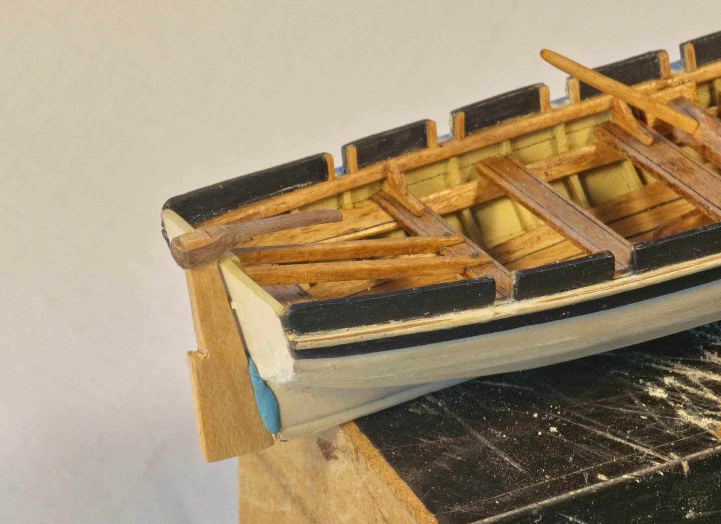
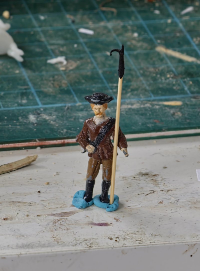
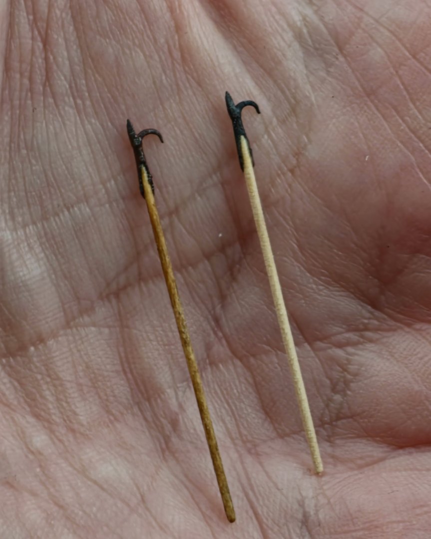
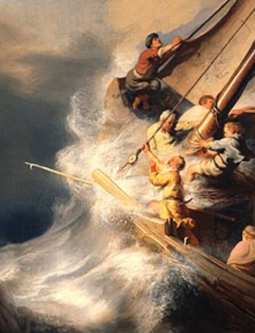
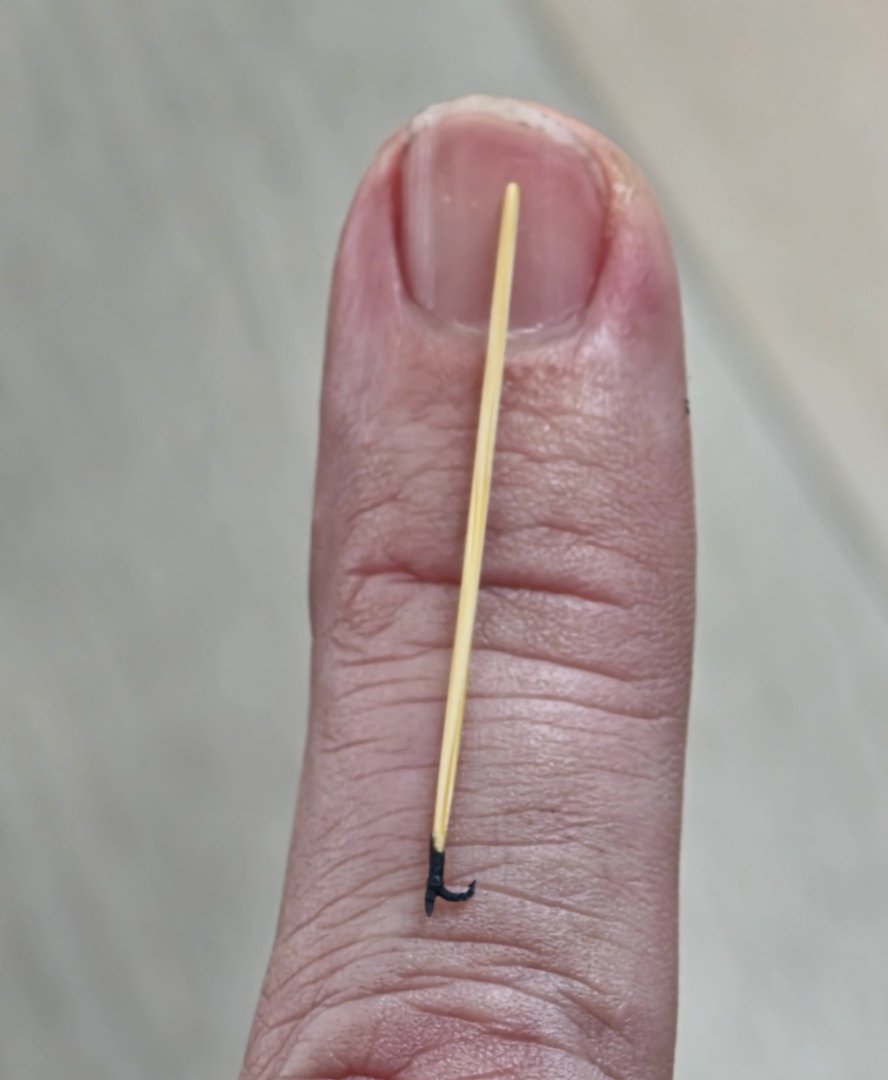
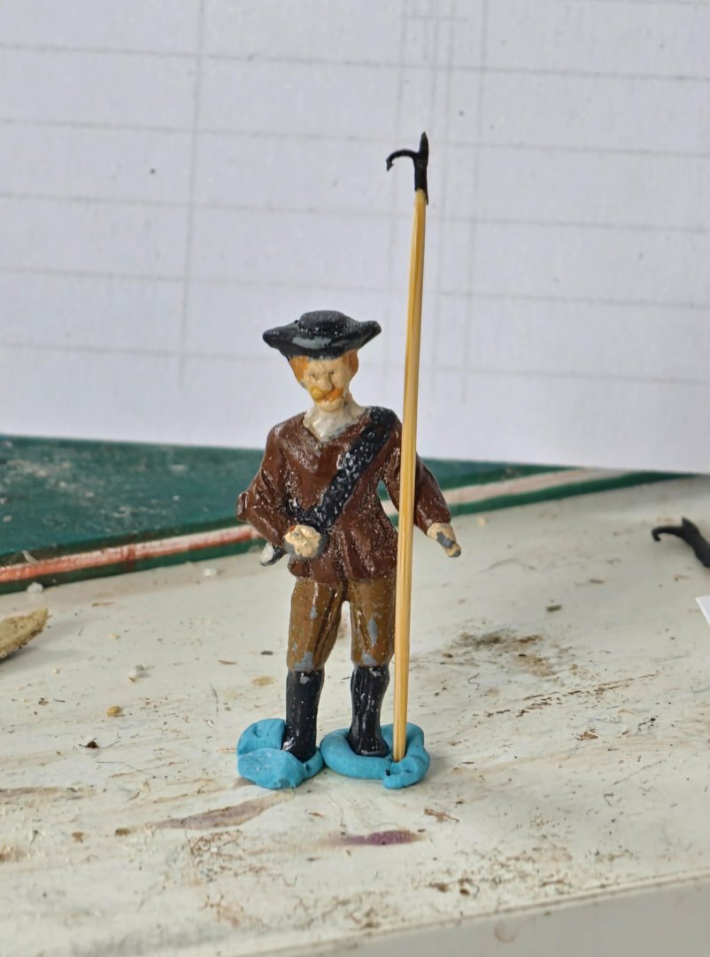
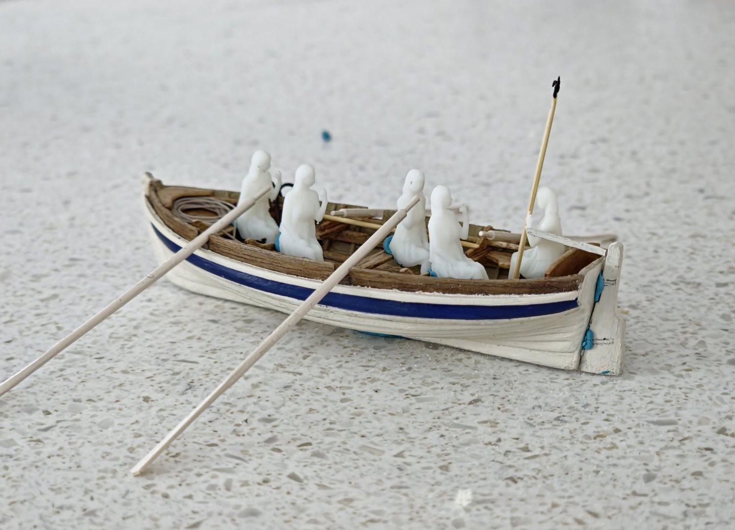
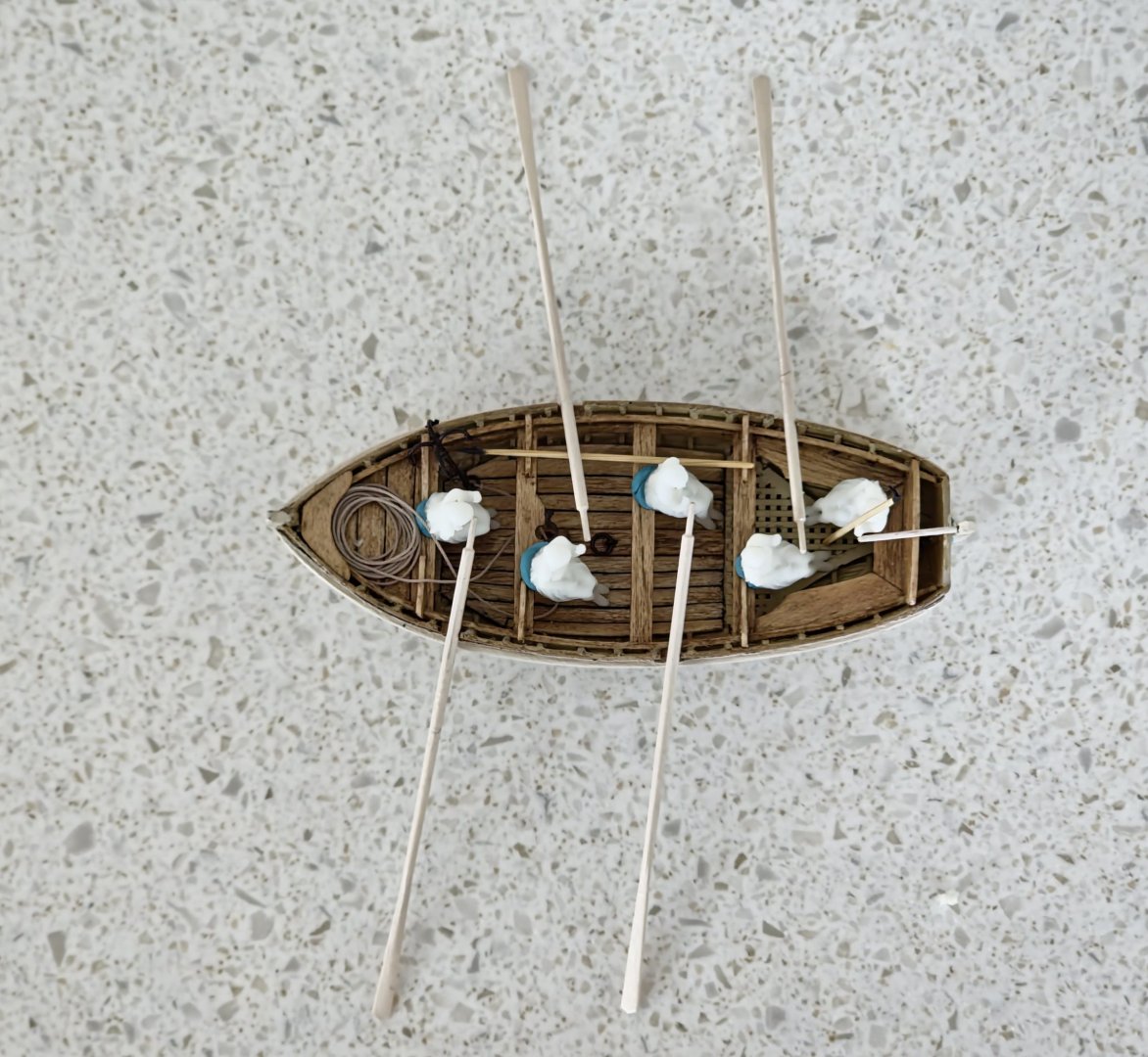
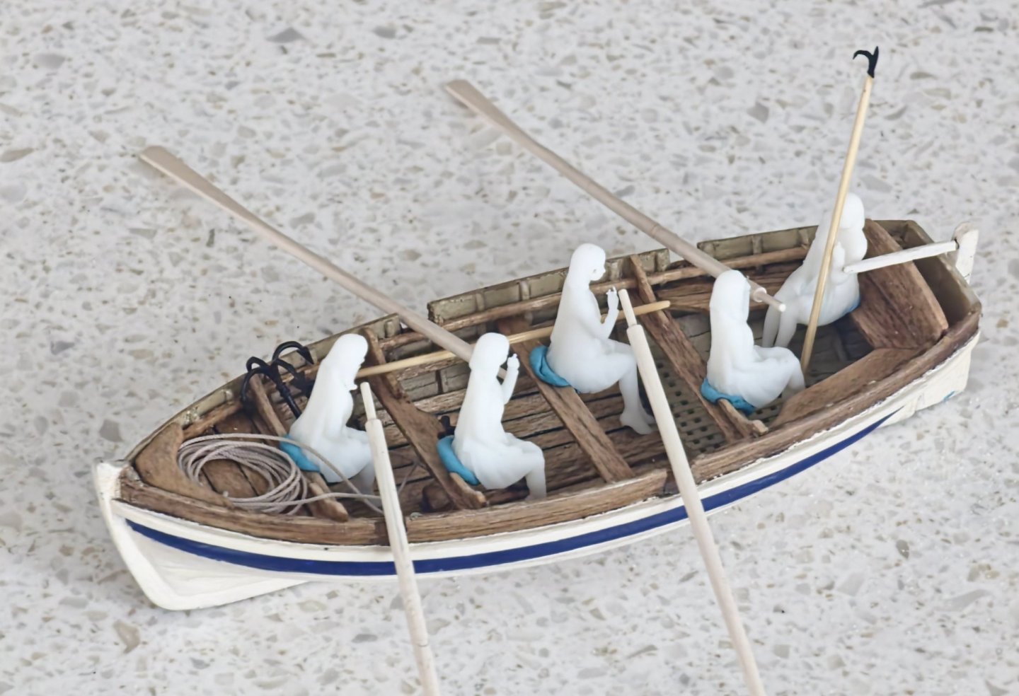
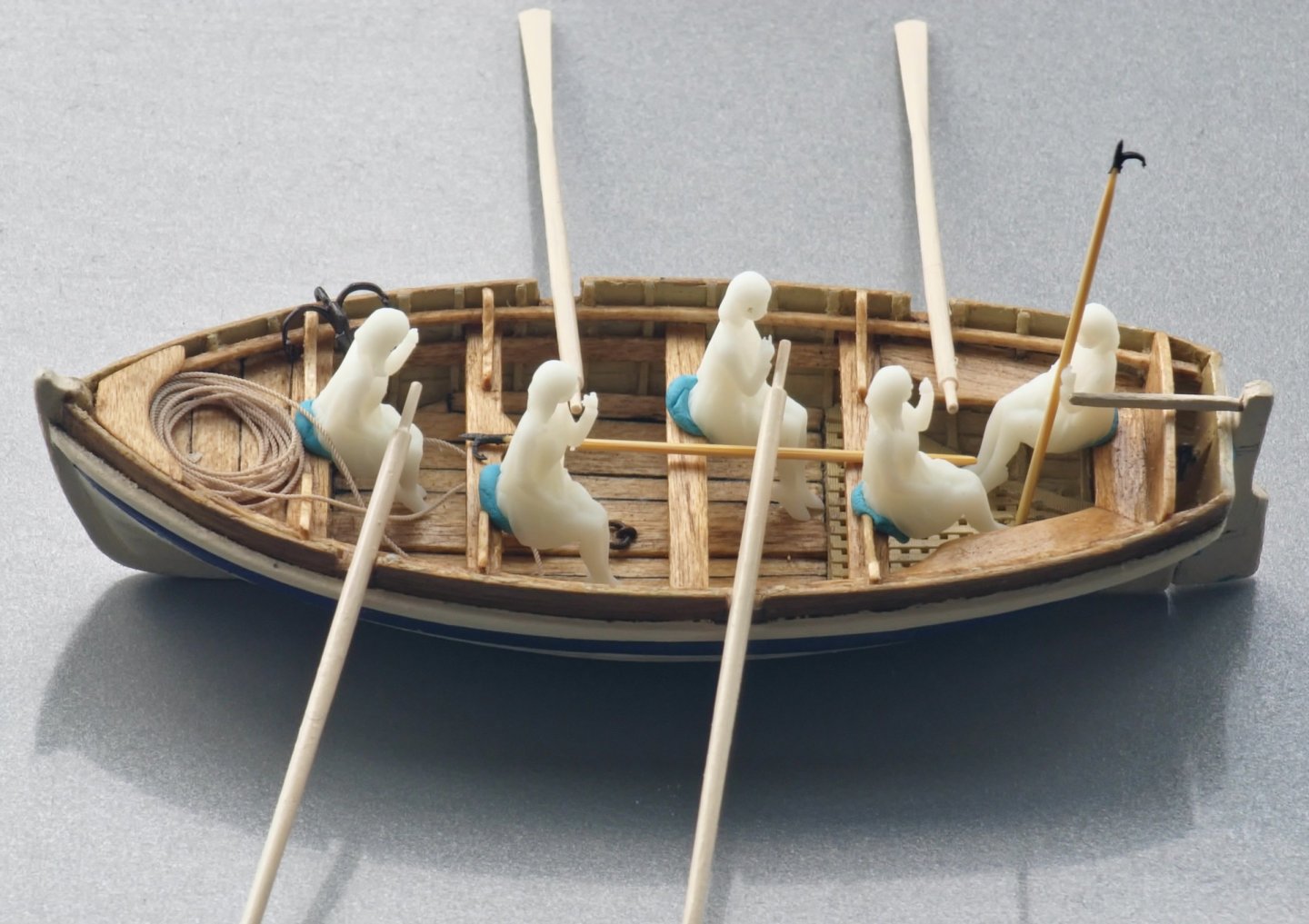
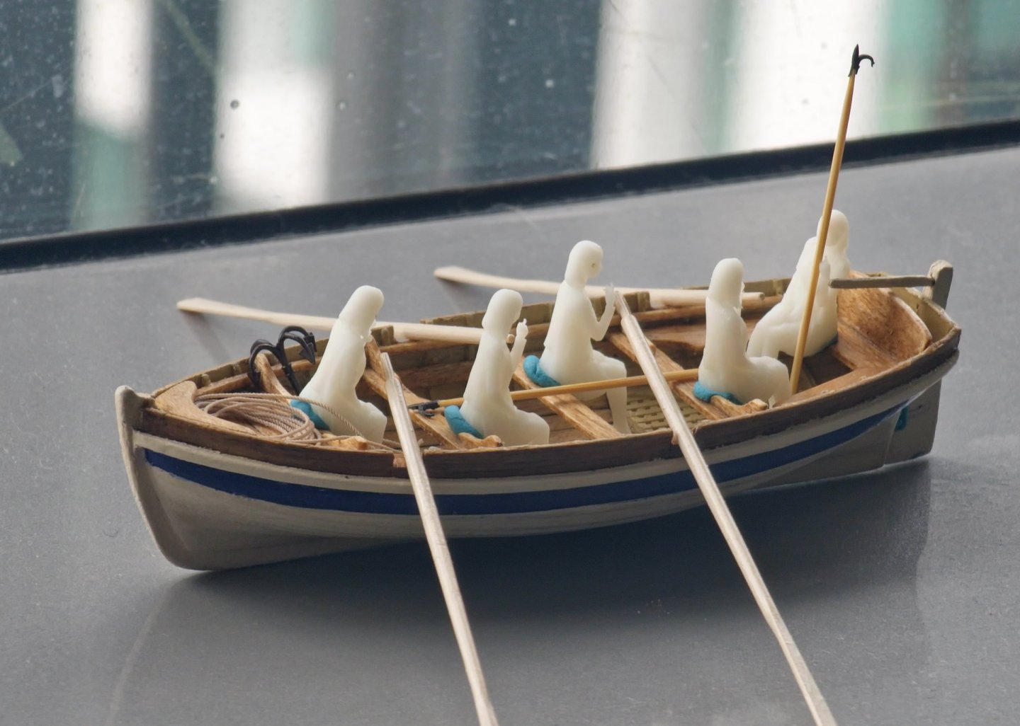
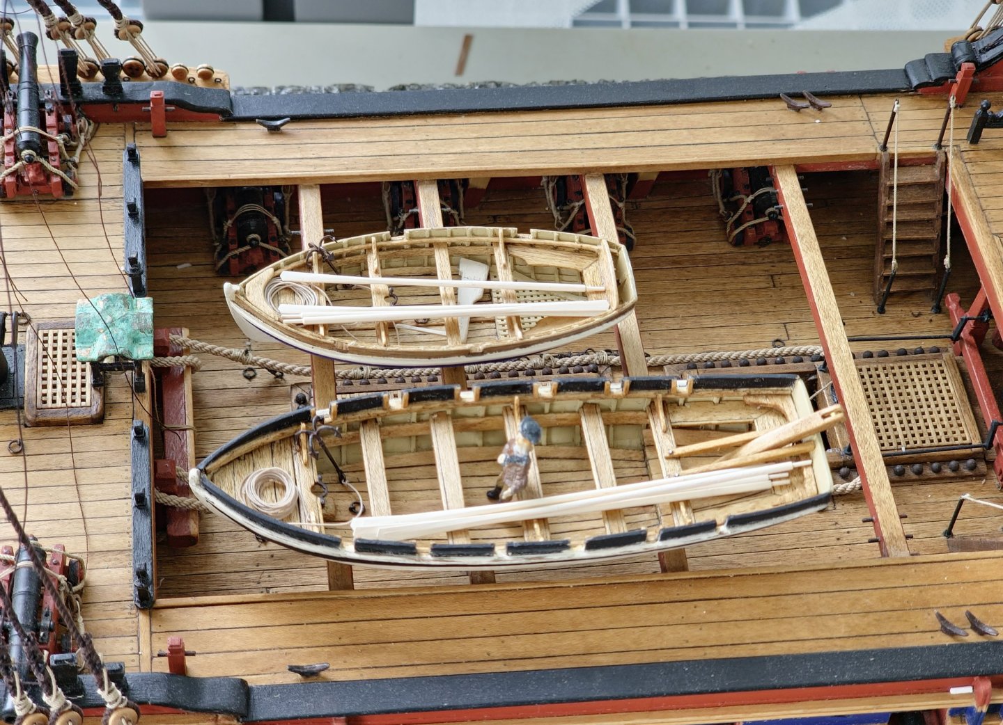
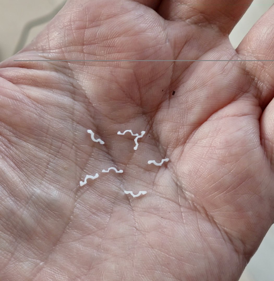
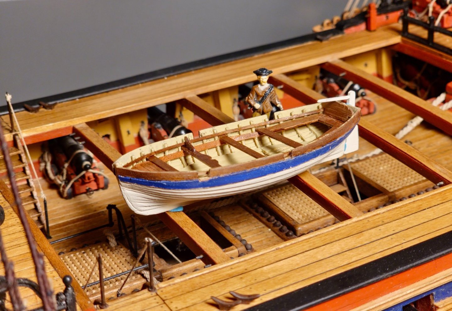
A minor update. I decided to press on and get the last bits and pieces of the launch out the way. These were the breasthook, windlass and rudder. They are fiddly little pieces that take a lot more time than their size would suggest. I did not have maple of sufficient thickness for the windlass so I ended up sandwiching three thinner pieces together. This was a particularly annoying piece to make. I cut the chamfers on the milling machine but it was one of those pieces where one false move out of the countless moves meant that I would have to chuck it out and start again. This happened on more than one occasion. Fitting it into the hull was also quite challenging but I used some thin-walled brass tube for the housing and brass rod for the axle to ensure that it does indeed turn. I drilled a hole in the side mounting block and then glued the first one in place and the fitted the second one along with the windlass. I had some problems with my geometry but I am not going to worry too much about it as it is pretty much hidden by boat structure. Handles were shaped out of 1.2x1.2mm maple. It took several goes for the breasthook as no matter how I orientated it I was always left with a terminal weakness due to the grain of the wood. I persevered and eventually got one that did not snap in two which sadly was not the shapeliest one. I fashioned the rudder and then tried a new tiller arrangement. I carved this out of a block of walnut. It looks quite clunky but I was a bit fearful of thinning it down even more as it was very fragile and I felt that it was about to snap with every pass of the file. It might be a piece more suited to 3D printing. I have yet to settle on the pintle and gudgeon detail. They are too fragile and I keep knocking them off. I may have to resort to epoxy. Another piece of equipment that I added at this time was the boat hook. I had previously made one on the CAD according to the size of a historical example but this turned out to be far too small to be printed out successfully so I had to exaggerate the dimensions to get something workable. I doubled the size but this looked a tad overscaled when sat next to my trusty sailor. I wanted something more in keeping with the example shown in the famous 17th Century Rembrandt Van Rijn painting. This is over 100 years earlier than my version but I suspect that boat hook technology did not advance much as the hook on the end of a pole concept is hard to improve on. You can buy similar models today although newfangled aluminium telescopic poles are now de rigueur. I tried to print out a smaller version, which was the devil to work with, but I am happier with the result. I initially printed it out all in one piece with head and handle but then decided it would look better if I printed the head separately and made the pole out of wood. I thinned out a toothpick to around 0.8mm diameter using sandpaper on the lathe. This equates to two-inch diameter in real life which is not outrageous. I made them around 2.4m long or just a shade under 40mm. I printed out 42 of the smaller heads and managed to safely release only 9 from the support raft and lost 3 of those to over-exuberant tweezer action and another two mysteriously vanished leaving me with a paltry four that made it onto their poles. I had noticed that during some of BlueEnsigns build logs he populates his craft with a scale seated sailor figure to check the height of the thwarts and to see if everything is in place. Not wishing to over capitalise on the build, I thought that I could probably find a similar seated figure online for free and then print it out at home. I admit that I did not spend too much time searching but the only free seated figure I could find was a well-heeled Japanese lady. I figured that it would suffice for my purposes so I printed out a few to sit about in the boats and test out the equipment. Please note that this is just an exercise to check the scale of the built elements so I hope there will be no lectures about how it would be highly unlikely that an 18th century ship's boat would be crewed by posh Japanese ladies in high heels. It was a fun but quite useful exercise as it gave a good illustration of the size of the boats and the heft of the equipment that I had produced. I had initially thought that this equipment too delicate but it turns out that I am erring on the beefy side. I am not going to do anything about it as I am at the limit of what I can produce with my shaky hands. I may have to consider the jump to 1:48 scale should I ever get round to finishing this ship and starting another.


-
Thanks Dave. They are tricky little blighters. Regards, David
-
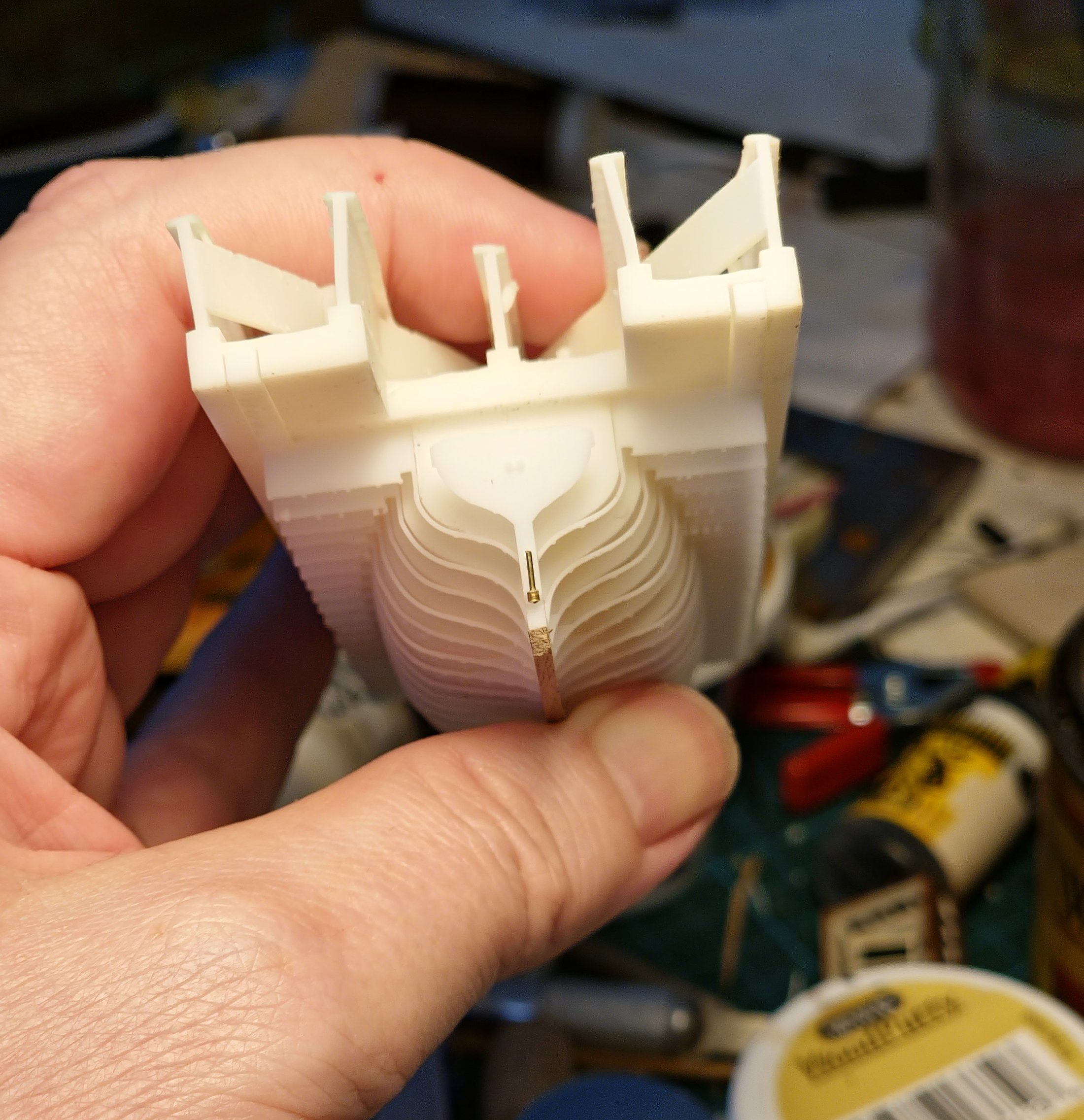
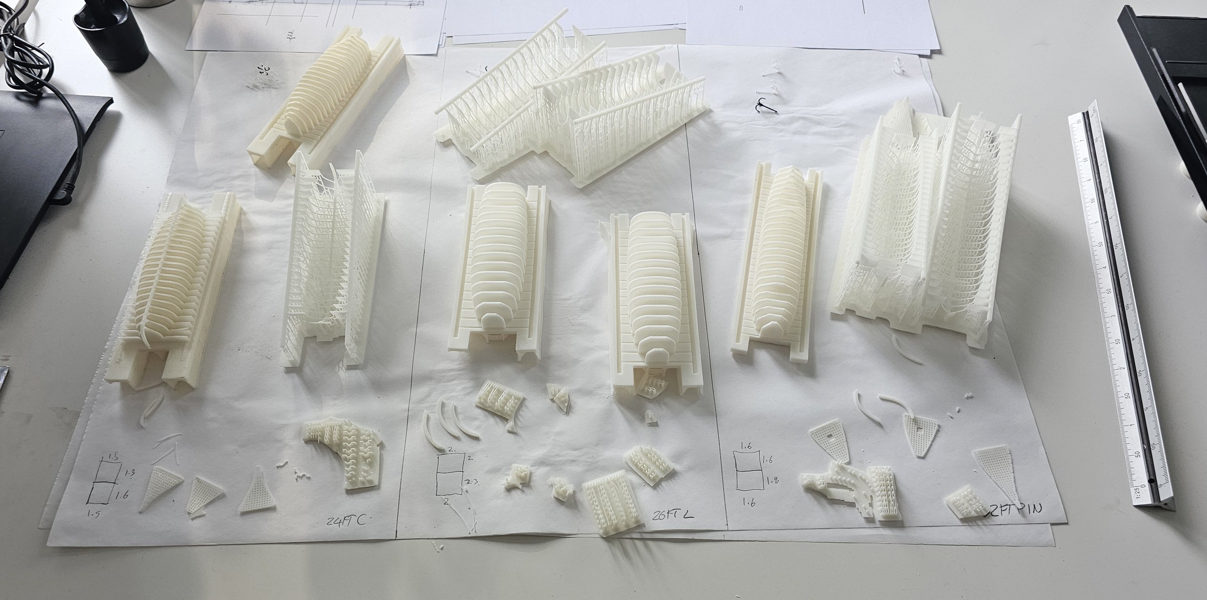
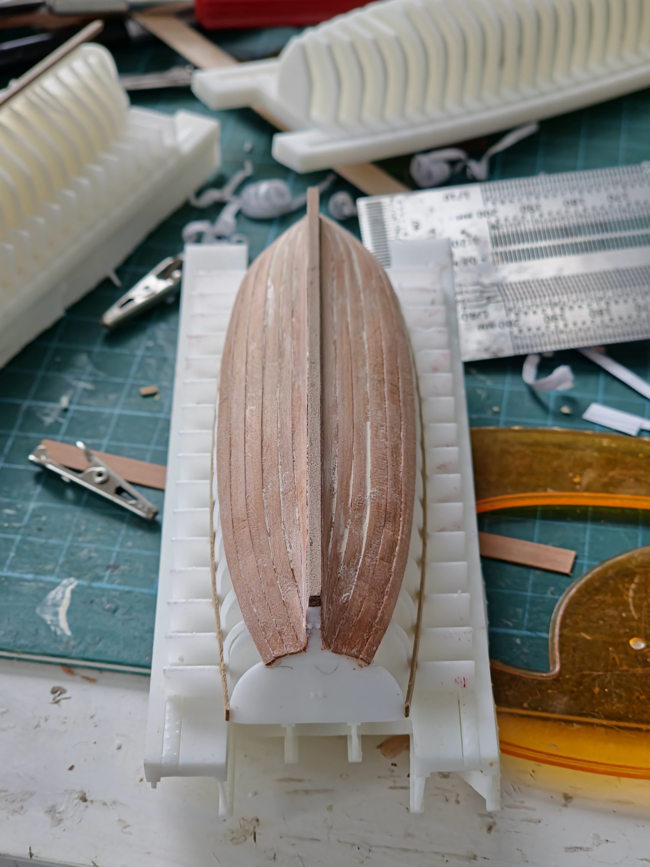
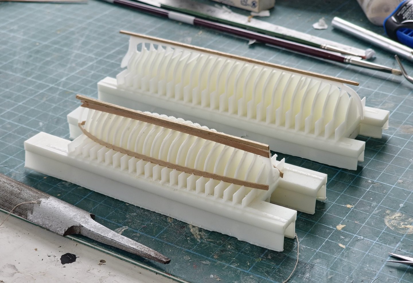
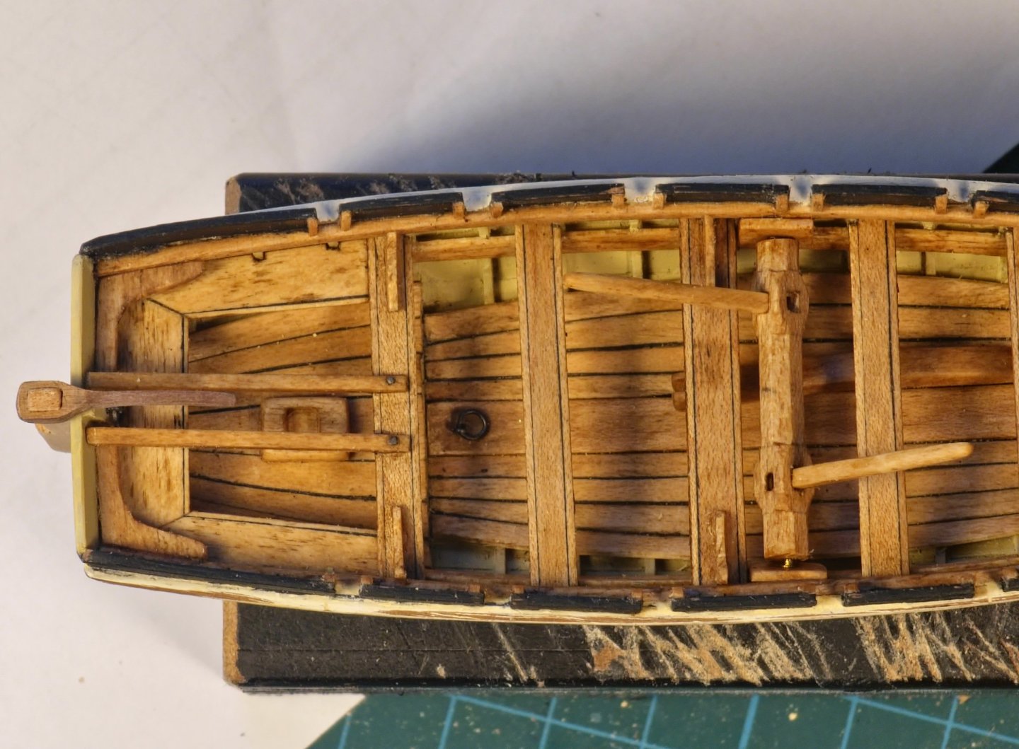
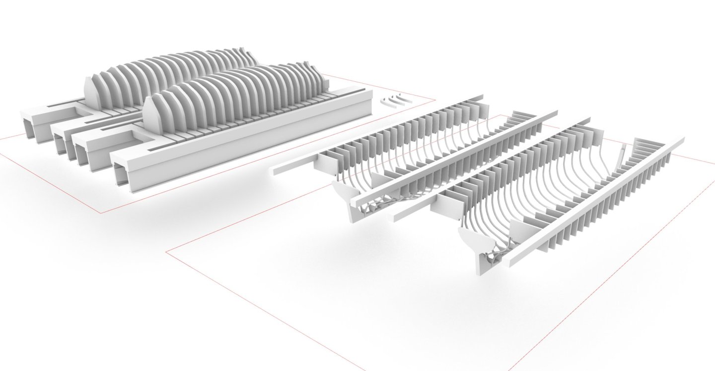
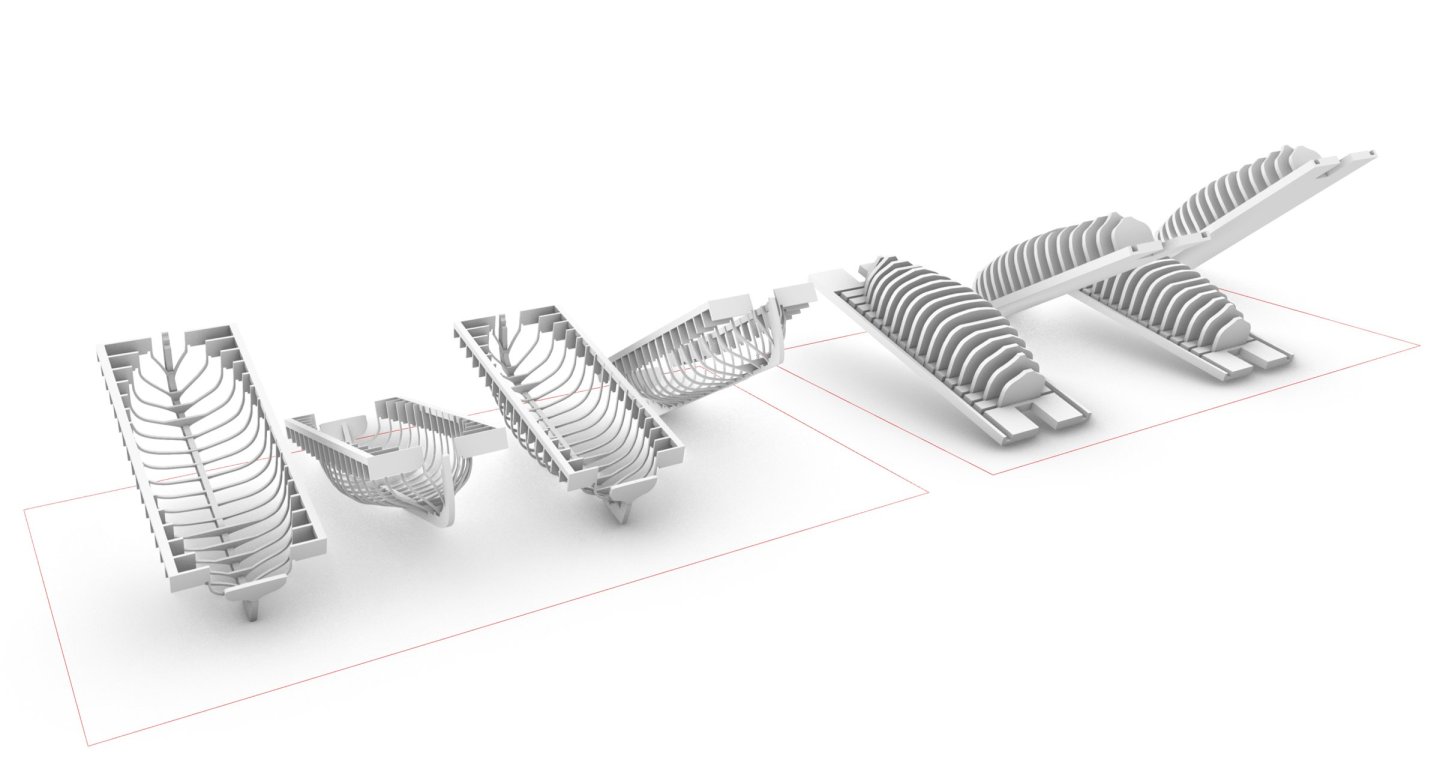
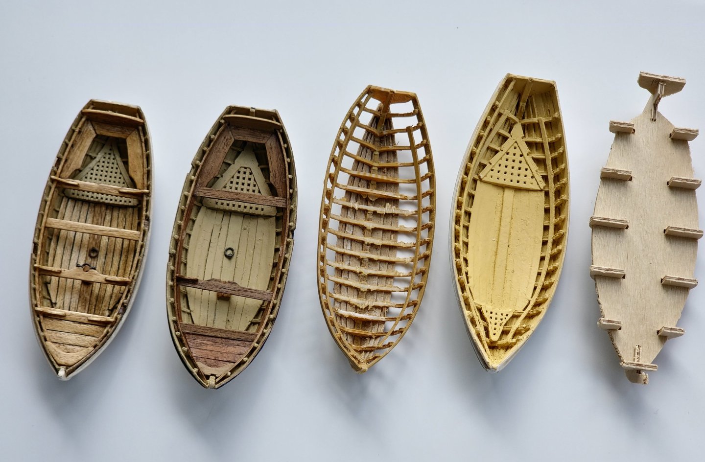
After completing most of the work in the jolly boat I had the urge to do something other than another small boat but much like washing the dishes or writing the minutes of meetings it is always best if you leap on to them straight away and not let them fester otherwise, they will never get done. I therefore decided to try and build the remaining three small boats concurrently. That way I would be able to capitalise on the recently acquired knowledge while it is still fresh in my mind and I should hopefully be able to get a good rhythm going and muscle through all the CAD work and then have a couple of days devoted to printing rather than doing it piecemeal thereby tripling the amount of cleaning of equipment. I was on the fence as to whether or not to include the 24ft cutter but decided to press ahead and build it. I can then make the call later if I should install it. The basic techniques for the additional boats are pretty much the same as the jolly boat although every time I make another one, I tweak the 3D models somewhat to try and overcome difficulties encountered in previous attempts. I noticed that the formwork for the jolly boat started to bow as it sat on the desk. As I am new to the resin printing world I do not know if this is because the base is too thin to resist the stresses of curing or if the base is too thick and the mass of resin is imparting additional stresses during the curing process. To attempt to mitigate this I added some fanciful engineering to the base of the formwork to hopefully keep this straight. This did not work perfectly in practice so I have come up with some other ideas to achieve a better success rate if I should ever again attempt a small boat. This new technique would involve adding metal or wood stiffeners as soon as the print was free of the support structure. The 3D model would be modified to accommodate these. The cutter is just a slightly bigger version of the jolly boat but with slight modifications to the floor and grating. I had been thinking about how to tackle the pintles and gudgeons on the jolly boat and it is causing me no end of headaches. BlueEnsign has some good information on how these work in one of his build logs with the longer lower pintle that facilitates installation in rough seas. It occurred to me that I could save myself a step if I included the fixing points in the 3D model which should help with stability and accuracy. I figured I could make the pintles out of 0.5mm diameter brass rod inserted into 1mm diameter thin-walled brass tube. It is very easy to draw this but building it will be a lot more difficult given the tiny scales and I doubt that I will be able to achieve acceptable gaps and tolerances between the keel and the rudder. Once the model has been printed out the fixing point is a microscopic blob of resin. Once you zoom in using the magnifier function on the phone you can see that all the detail is there. It is just not visible to the naked eye. The launch is a different beast from the previous cutters. It seems to have wider spaced futtocks that are slightly beefier. The breadth is nearly 8 feet so I am making this one double banked. There is also a lot of additional equipment with the windlass and davit and it is carvel built rather than clinker. Lucky there are no gratings which are a pain to draw but it does mean that I will have to do some in-situ planking later so swings and roundabouts. The 32ft pinnace is also carvel built but closer to the cutter in terms of the distribution and size of the futtocks. It is quite narrow so will be single banked. The drawings in the AOTSD show a bench running down the middle. I have noticed in some drawings and models that there are small posts that sit on the keelson and support the thwarts. I am not sure that I will include these. The detailing of the pinnace looks like the most complicated of the three and will need some further study. Although quite tedious I sat down and built the three basic structural models as well as the formwork upon which they will sit. I printed out two of each as there is a lot of potential for breakage when liberating the models from the temporary support structure. The total print time for everything was just over 18 hours so it is a two-day exercise which works out quite nicely as I am using two different types of resin. I had to clear a space on a desk to keep all the pieces segregated before I started on the assembly as I did not want to get them muddled up. I had the idea of completing all three hull planking exercises at once. The advantage of doing all three at once is that you can paint them all in a production line which is a good saving in time over than doing them one by one. The disadvantage as it turned out is that all of the hull planking at one go is too much for me to stomach so after planking the launch I decided to carry on building the rest of it to break up the monotony. I used the same basic colour scheme as the jolly boat except with a black identification stripe. The washboards are looking a bit tentative though, so I will revisit those later. As it is so much larger than the jolly boat the area of white hull is giving me palpitations. I probably should have left some of the planks au naturel and just painted below the waterline but too late for that now. I used the oak stained maple for the footwalling but went for a slightly thicker plank as the in-scale version was prone to disintegration. There are no gratings but there is some steensheet footwalling which was also made from the maple. The AOTSD drawings do not show any lifting ringbolts but these are present in all the other small boats so I am inclined to blame a lazy draughtsperson for their omission and included them on the model. The rising and thwarts are also maple. May notes that the main thwart is wider and thicker than the rest. This is a detail too far for me so I kept the same thickness throughout but increased the width of the main thwart. I did make them fancy three-piece thwarts though but you really have to peer closely to pick this detail up. The overall shape of the launch is causing me some concern. I have been dutifully following the dimensions set out in the AOTSD drawings but it looks quite beefy in the backside and quite deep dish. I was wondering if I had bungled spectacularly in transposing the dimensions in the CAD process but when I lay it over the drawings it does match up so it may be that I just overdosed on the Jolly boat shape after building so many prototypes. I knocked up the davit and support structure out of maple with wire simulating the bolts. The sheave was lathed out of some 2.5mm diameter brass rod with a 0.5mm diameter brass axle. I added the transom knees and the various steps. I then tried to replace the washboards with some that are slightly thicker although the demolition phase caused much grinding of teeth and destruction of parts of the model that were not slated for demolition. It ended up a bit of a bodge. Still looked a bit funny so I added some reinforcement pieces at the rowlocks, which is a detail I have seen before, to tidy this up. Knees were installed on the fixed thwarts. I was dithering about which anchor to include I was going to use the 78lb version as it is quite a hefty craft but Lavery hints that these boats would be equipped with a 40lb version. I may go with my smallest one which is 54lb but there is not much visual difference between the two to be sure. I must add the breasthook and then tackle the windlass which looks like quite a fiddly little exercise. I also need to print out some additional oars as I only have four of the 19ft versions although while poring over the drawings of the windlass I noticed that I will not be able to present it with the oars laid across the thwarts as the windlass sits above the level of the thwarts. Perhaps I will leave off the launch oars in the final setup. I still need to touch up the paint job but I think I will move on to one of the remaining two boats for a change of pace but the fleet is growing albeit slowly.


-
Hi Dave, I also had the problem with the missing lower chain plate straps and spent some time making them myself. I subsequently discovered that Caldercraft had included the missing ones on the photo etch next to the ships wheel. Regards, David
-
Stunning workmanship and attention to detail as usual Jason. Regards, David
-
Thanks B.E. I have picked up a lot of handy hints from your various small boat logs. Regards, David
-
Thanks Jason. I am hoping that the other boats will be easier now that I have invested all of the time and money on the first one. I hope that we will not have too long to wait for an update on your Jason model. Regards, David
-
Thanks for the the kind words of encouragement Dave. Do not worry as there are plenty of challenging parts left on your Diana build that will provide a perfect opportunity to jump back in and finish your Endeavour for a change of pace. Regards, David
-
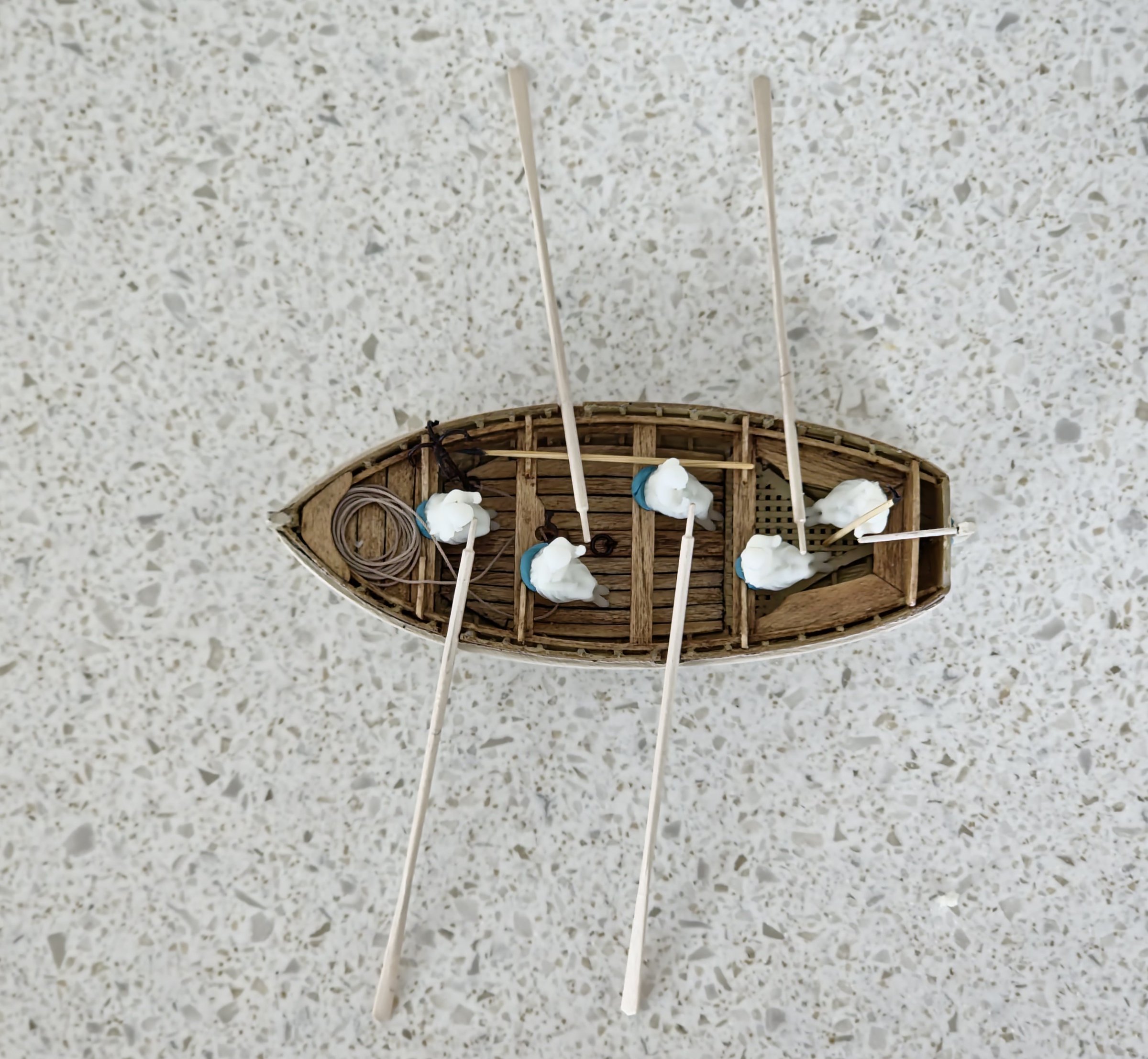
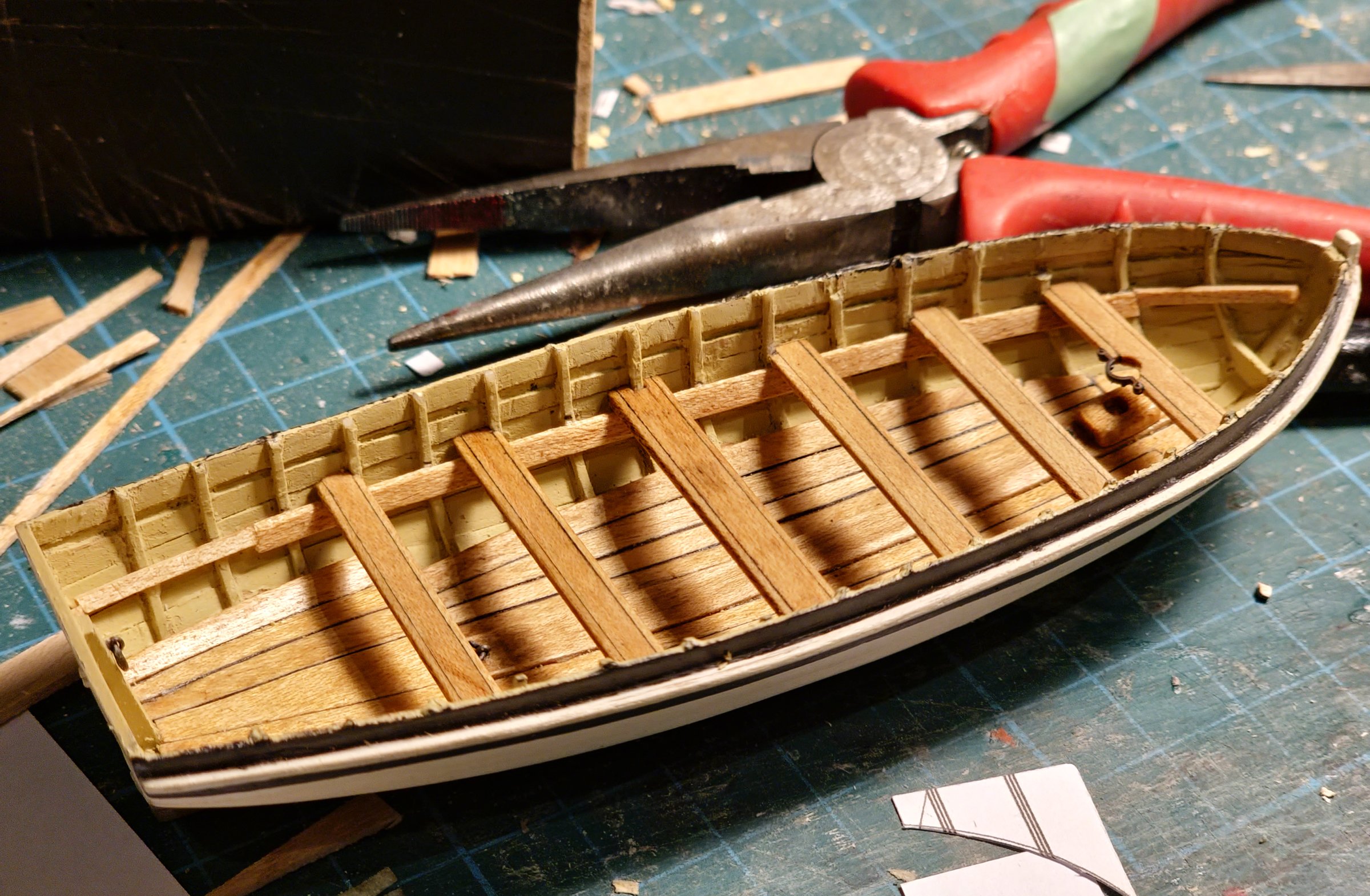
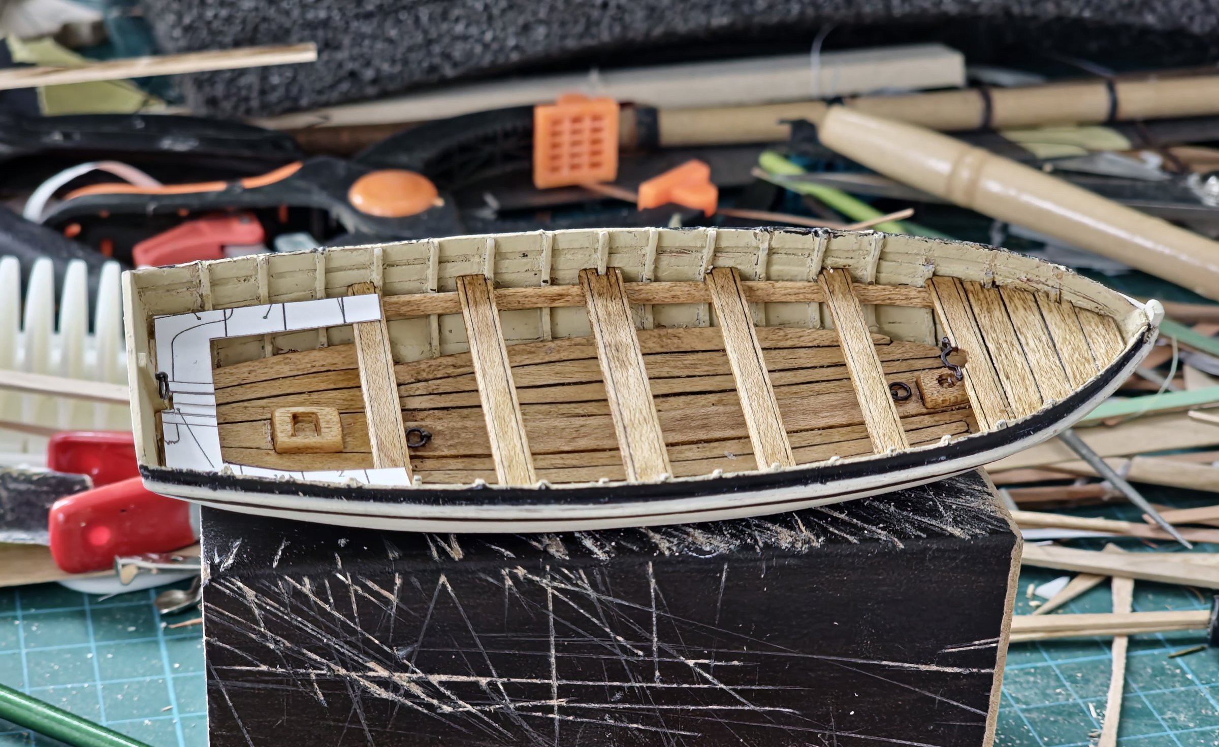
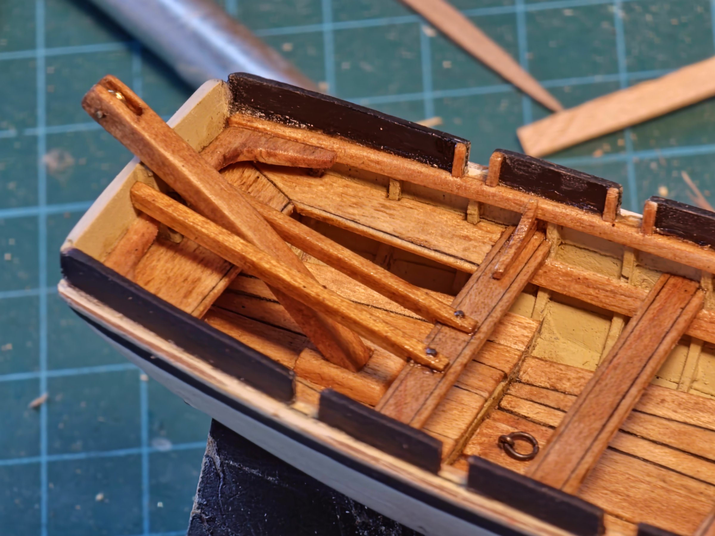
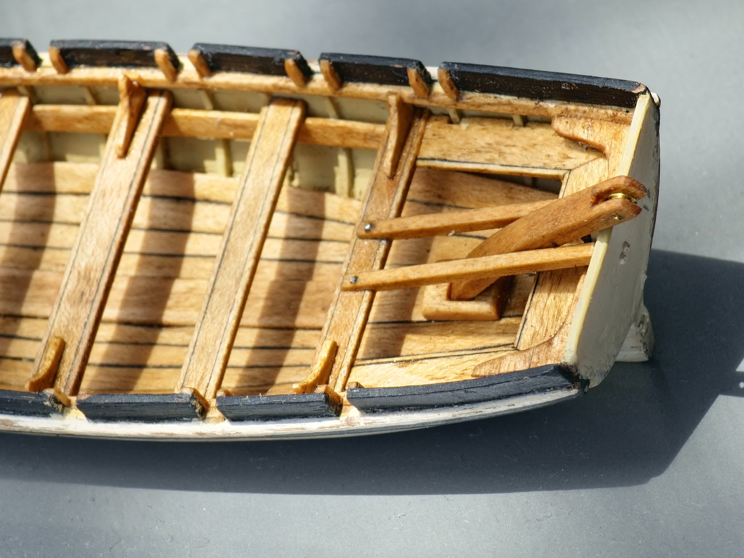
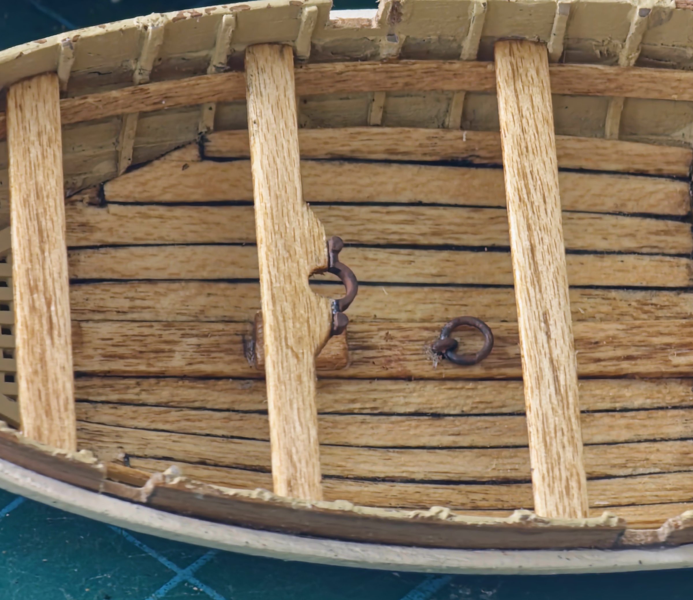
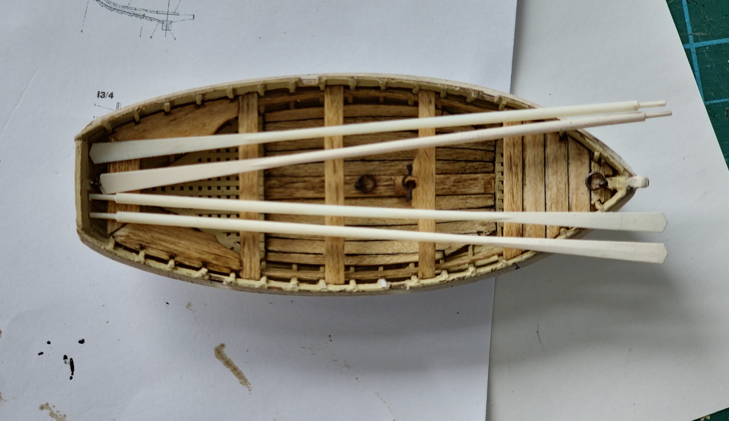
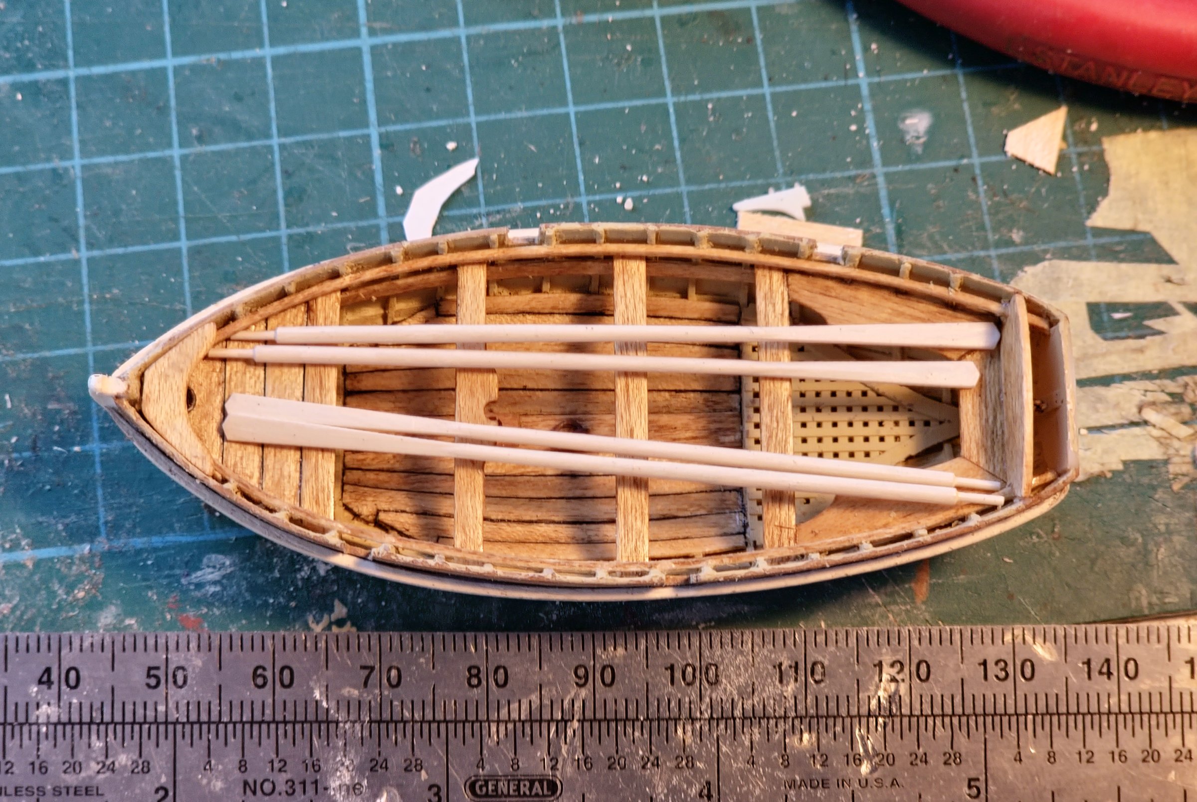
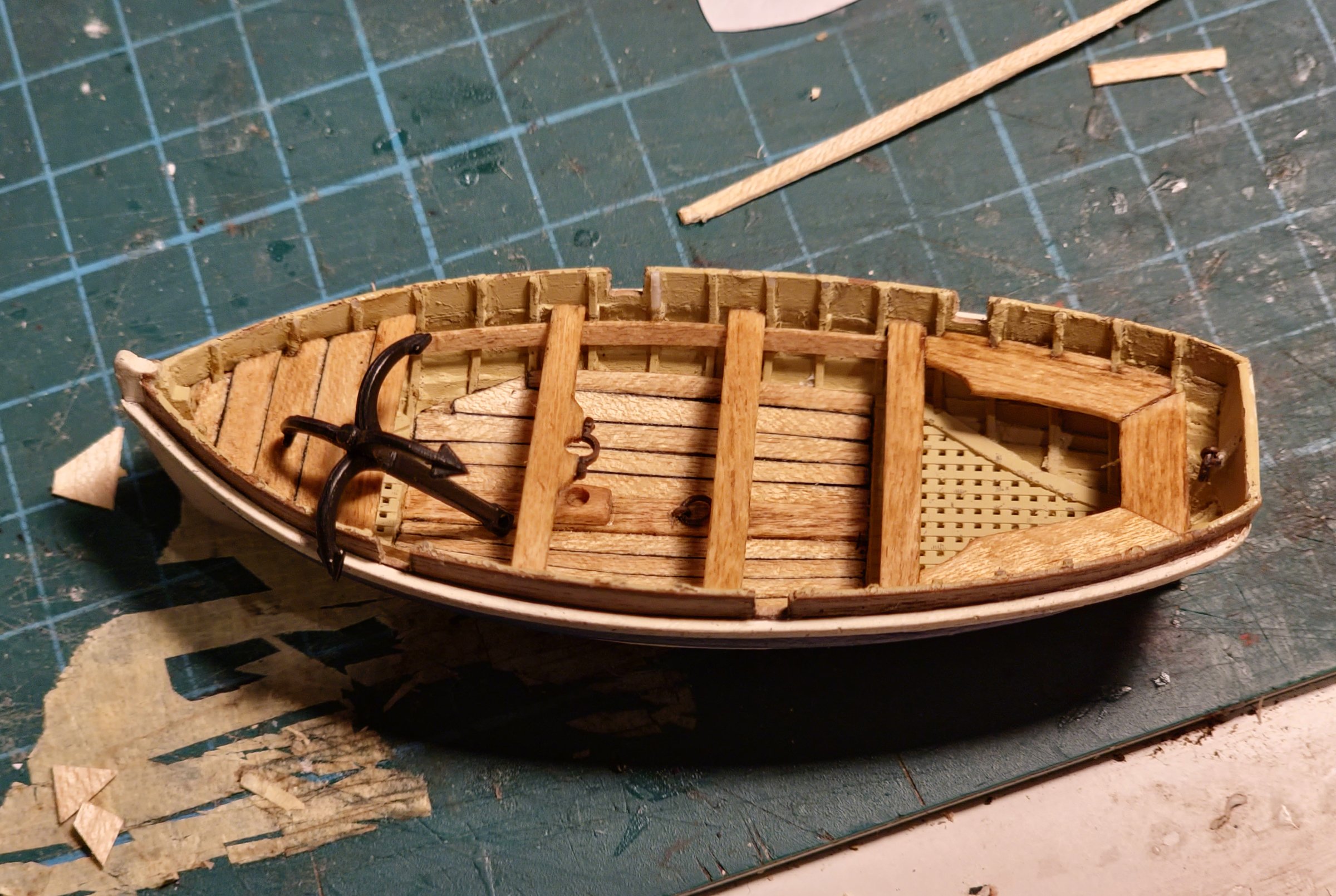
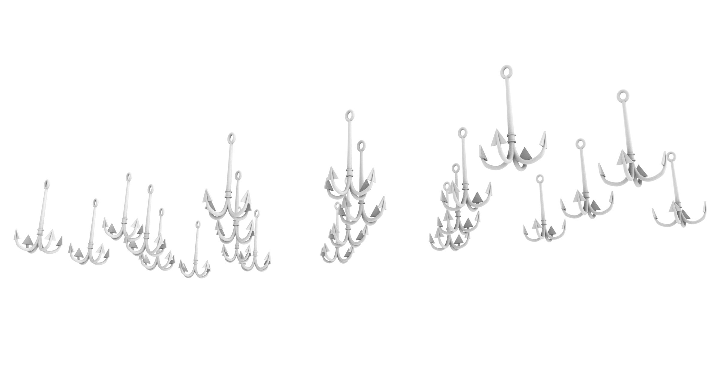
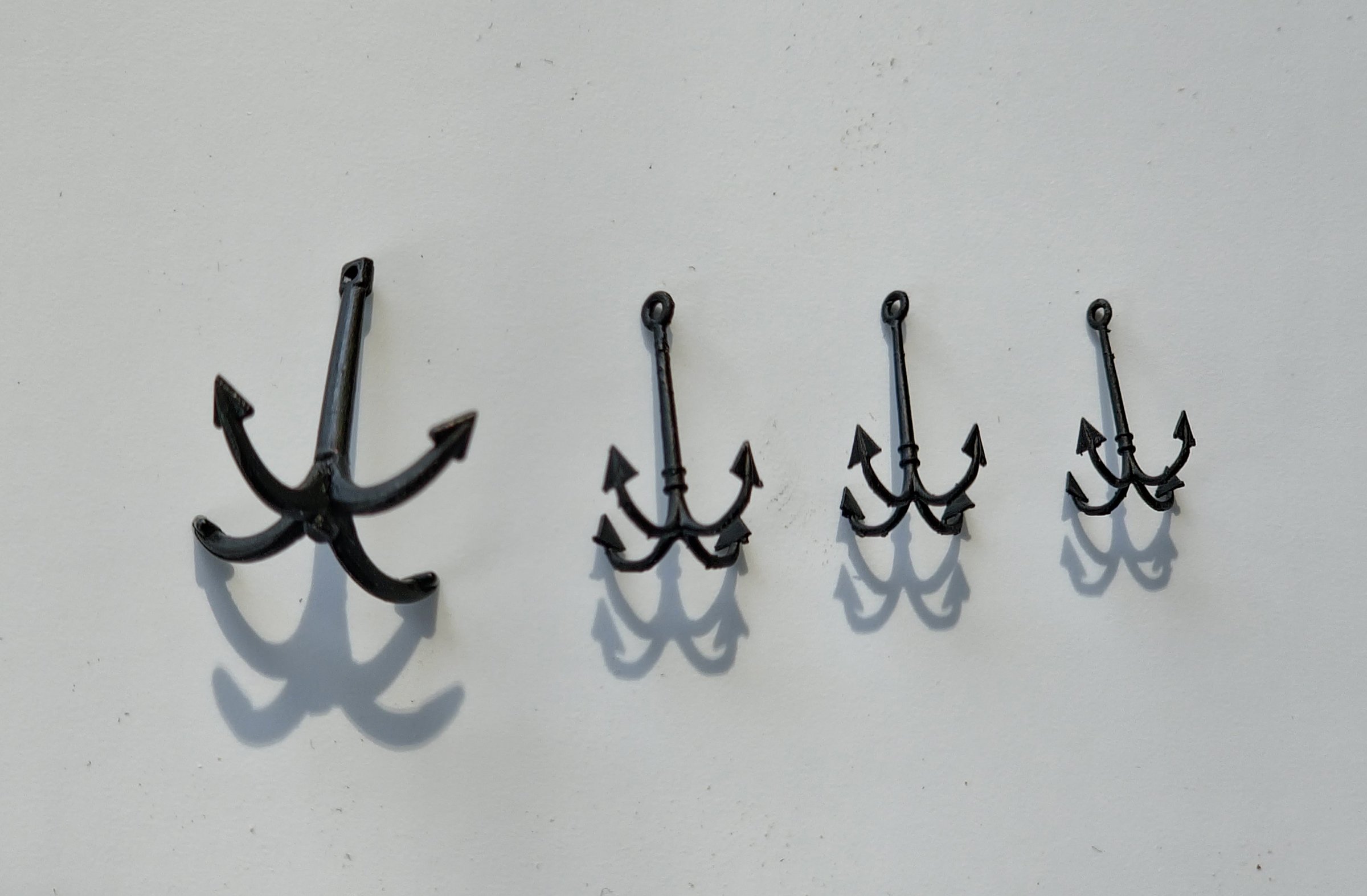
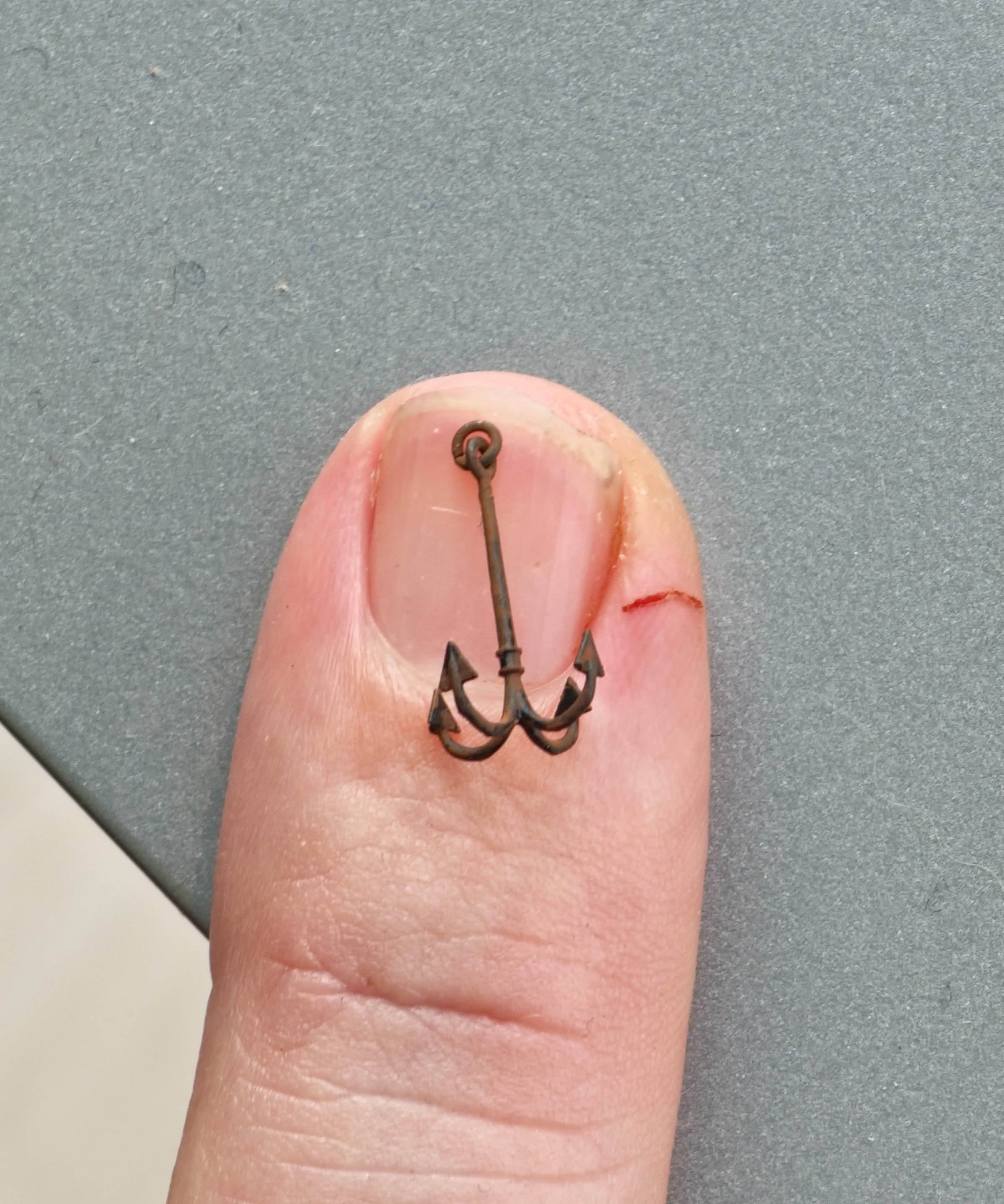
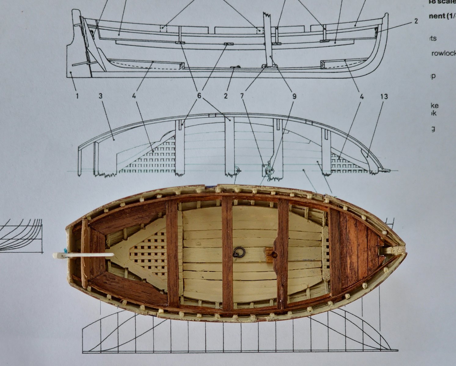
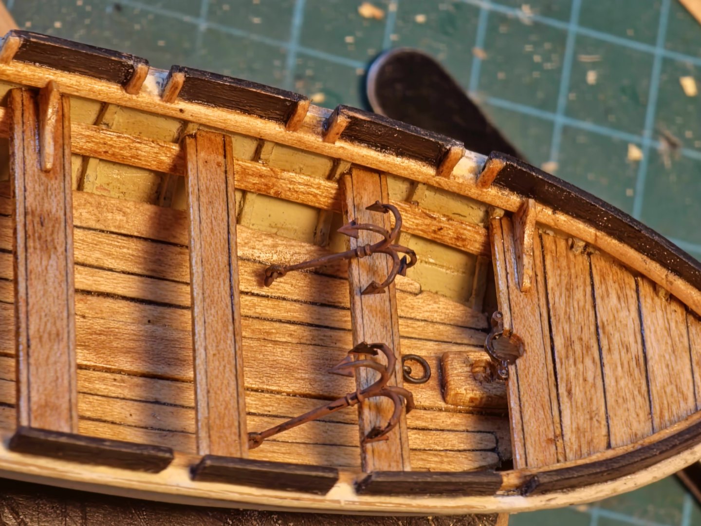
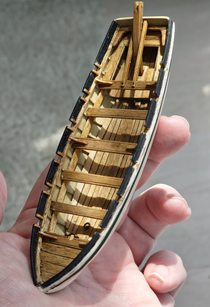
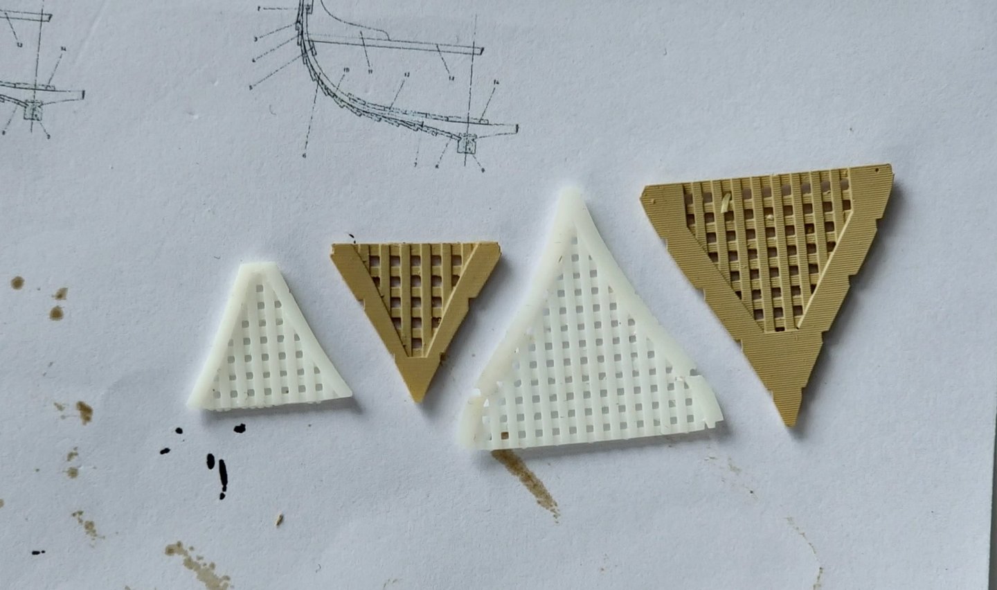
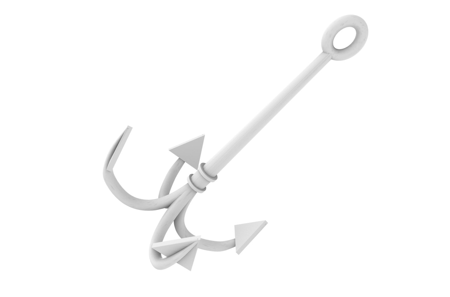
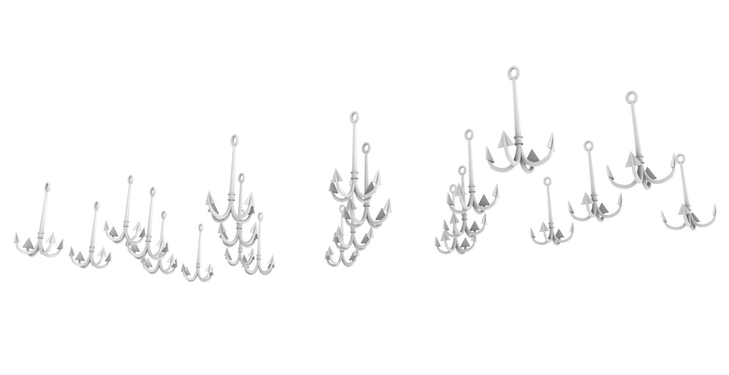
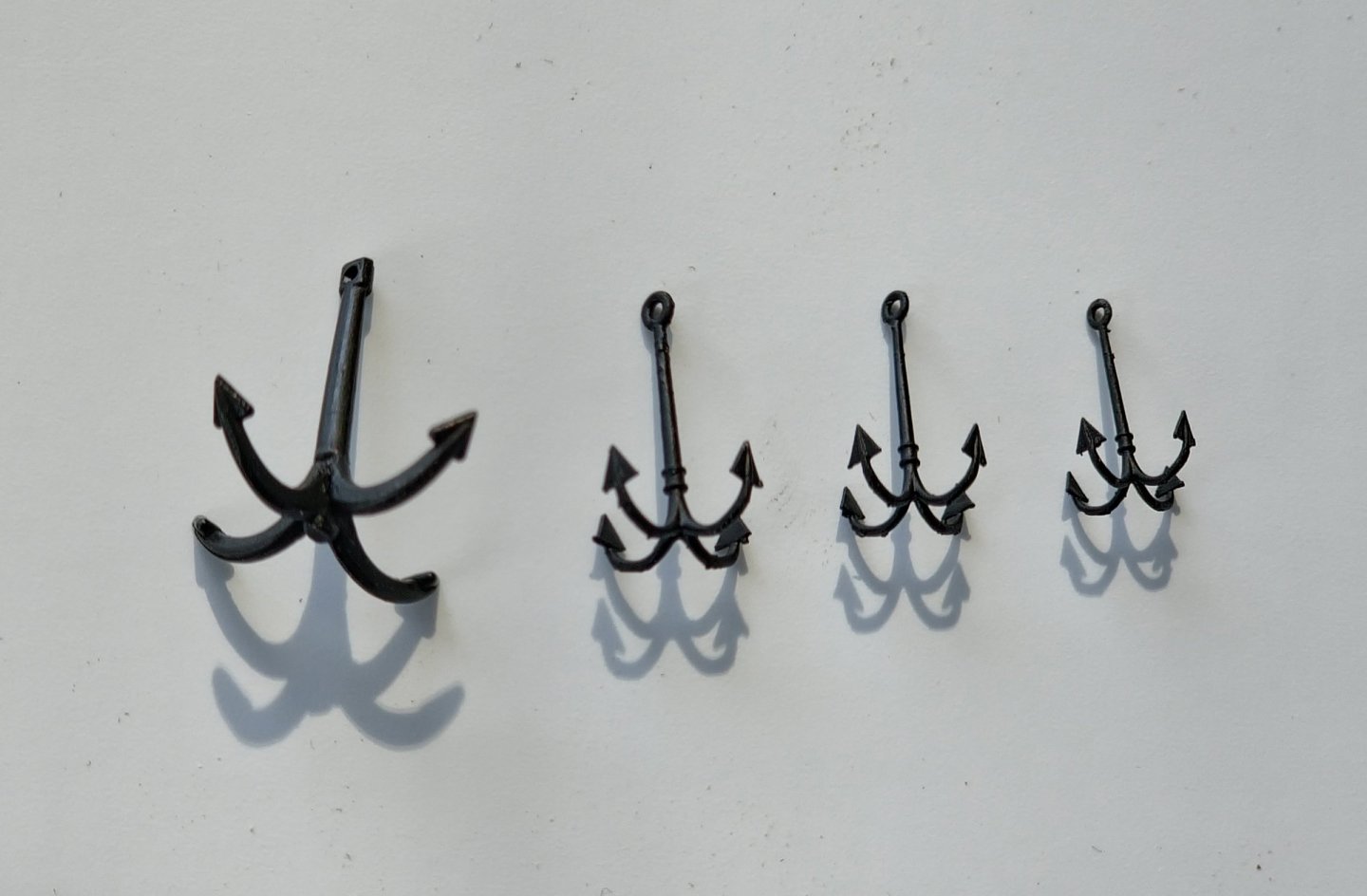
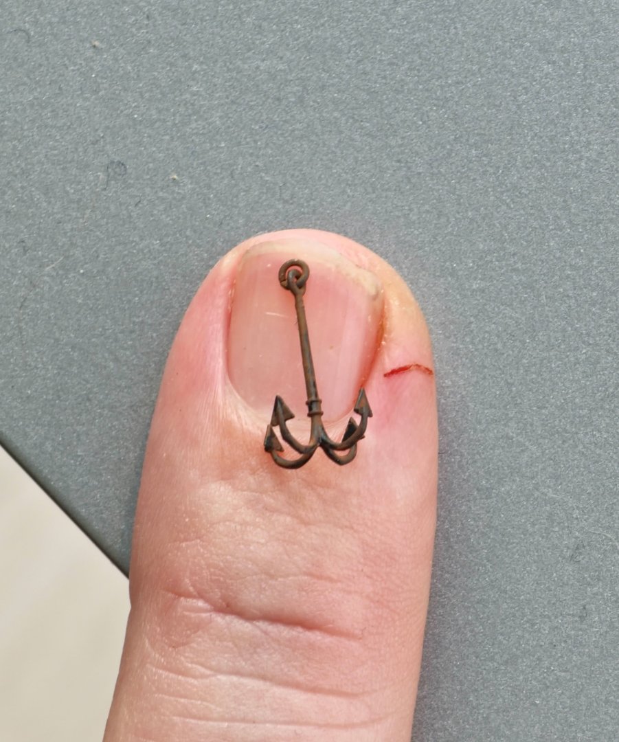
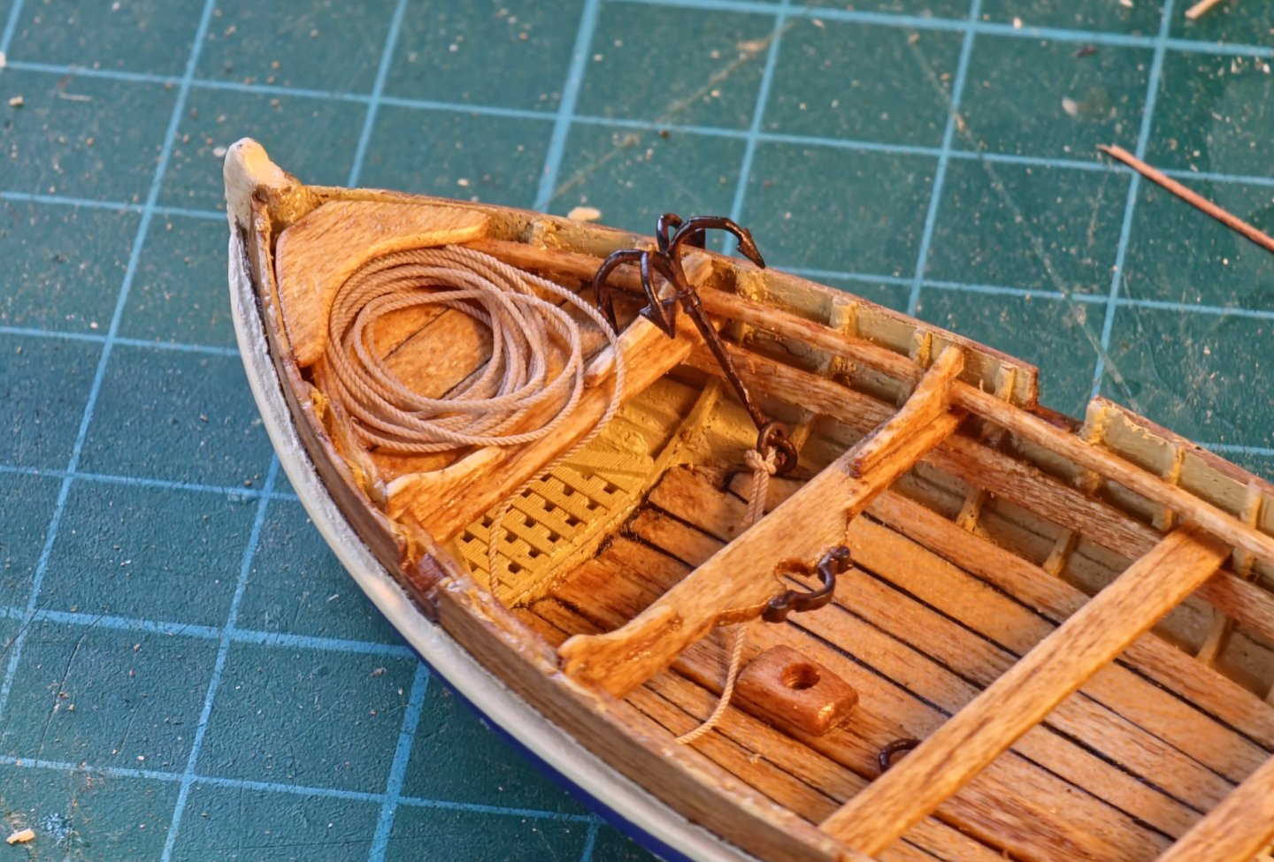
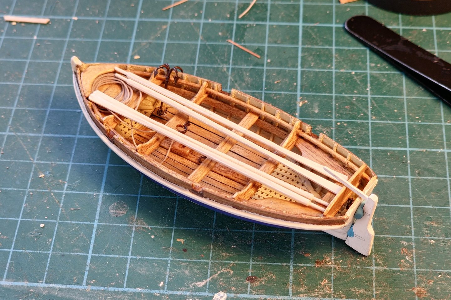
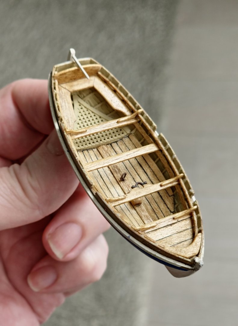
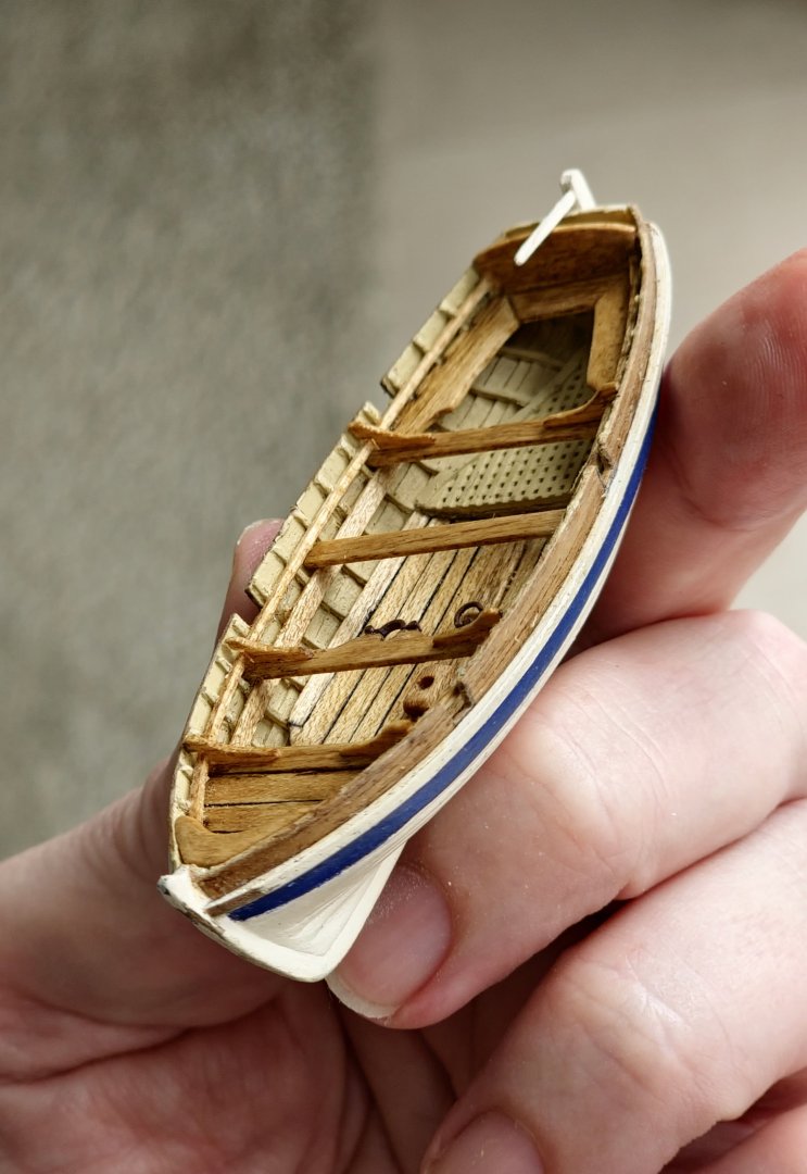
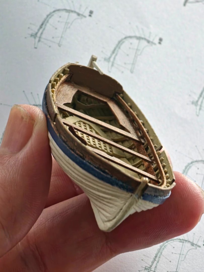
I foolishly stopped working on the model and I have had a real problem starting up again. This is the second time I have fallen into that trap. I should have learnt my lesson the first time. To get back into the swing of things I decided to have another stab at my nemesis, the 18ft cutter (jolly boat). I think that I am into double figures with my jolly boat attempts. I have picked up a thing or two from the previously discarded prototypes so I went back to the CAD model and made some modifications. I found that trying to insert the individual futtock heads into the formwork was a real pain so I joined them all together at the top with a sacrificial beam and then modified the formwork so that it could accept these beams which will allow the futtocks to line up with relative ease and they will hopefully remain evenly spaced. I went out and purchased some engineering grade resin to try and overcome the failure of the futtocks when releasing from the support structure. I found that it is advisable to put off the curing stage until later as this gives the material some additional flexibility and reduces the chance of sudden fracture. It is more of a faff to use as the model must be cleaned with alcohol rather than water. Once printed out I married the two components together and installed the wash strake first to overcome the futtock distortion problem I previously encountered. I then placed the rest of the keel, garboard stakes, and continued the rest of the planking in my usual haphazard manner. I start out with the best of intentions but soon lose my way. I had some real problems at the pointy end but I realise where the mistake lies and could modify the CAD model to mitigate this in future builds. I decided to just press on with this one as I could not face starting again. The good thing about the new sacrificial beam design is that I can remove the model from the formwork from time to time to see how it is looking from the inside. Not great to be sure mainly due to my munificence with the CA. Despite deploying the engineering grade resin, the dimensions of the futtocks give them the same structural integrity as the bones of a well boiled kipper and they snap off at the slightest touch. I had to replace some parts by organ harvesting from previous model prototypes but I am hoping that a thick layer of paint will keep everything intact. I gave the exterior of the hull a few coats of acrylic paint. I have fallen into the trap of going for a too white paint but I used something called parchment this time. I think I could probably go for one more shade shabbier, which was linen, as it still looks quite bright to my eye but that will hopefully dull over time as it picks up dust and grime from constant handling. I continued my tradition of the admiralty blue identification stripe and added a rubbing strake picked out in white to give it a racy feel. I kept the washboards in a natural walnut finish rather than carrying on with the blue just for some visual interest. For the interior I started off by laying down a few coats of light ochre colour. I found this in the model figure painting section of the hobby shop and it is apparently the colour of the bones of some mythical beast but it had a nice utilitarian look although I was rather taken with the light blue that BlueEnsign used in his pinnace on his Indefatigable build. I was not happy with the grating that I had 3d printed as the perimeter timbers were too wide. The geometry is quite complicated as it needs to fit snugly in the as-built space but I bit the bullet and redrew these to come up with something that was closer to the drawings shown in the AOTSD. I used maple for the keelsom and footwalling. I left this a natural colour with a golden oak stain to highlight the complicated planking layout that took me a while to achieve although the joints are messy and the shape somehow got distorted. This position of the footwalling was the whole reason for embarking on the jolly boat journey as it was sitting too high in the kit supplied version with no way of lowering it. Thwarts, knees, sternsheets, risings, gunwales and decking were all made from the golden oak stained maple to match the rest of the interior timber work. This also ties into the deck colour of the ship so it hopefully does not stick out like a sore thumb. I slightly bumped up the thickness of the thwarts over the dimensions shown in May as the scaling down of this element caused it to appear too insubstantial. I added ringbolts and other bits and pieces. I 3D printed the mast clamp as it is a very delicate piece. I even had to exaggerate some of the dimensions as the dimensionally accurate one was so fragile that it tended to crumble to dust in my fingers. I 3D printed some oars with a view to making them out of timber but once I had them in my hand, I realised that they are too delicate and would therefore be too frustrating to construct from any of the timber in my stock. For fiddly pieces that need to be produced in multiples, the 3D printing process is so much easier. I used the dimensions from Steel based on the 6ft breadth of boat but the length of the oar at 19ft turned out to be longer than the boat which was not what I expected. Further investigation revealed that the oar size can be in a range of 2.5 to 3.5 times the breadth of the boat. I noticed in May that he states the oar length for an 18ft cutter should be 14ft. This is however for a 19th century boat. I knocked out some a few 15ft examples for comparison, as they do not take that long to draw, and I am much happier with the proportions. I made the looms round as Steel notes these were often made round for the ship’s boats. Along with the oars there are other bits and bobs scattered about the boat. One of these is the anchor. Quite a while ago I had purchased the smallest grapnel anchor that I could find on the CMB website. This was a 20mm long version. I had to rummage around before I managed to locate it in the back of a drawer. I glued it together and tossed it into the boat and found out that it was much too large. I drew something up on the computer loosely based on the drawings and dimensions in Steel. I went with the four flukes rather than the five fluker he has drawn (and he does note both are acceptable). Even the slimmed down version was probably too big for the jolly boat and more suited to the pinnace. I scaled the original down in two stages based on what I thought might survive the printing process and came up with three different sizes. Steel notes that the weight for these anchors ranges between 112lbs to 30lbs. An advantage of working in CAD means that I could get the volume of the model and thus calculate the scaled-up weight. The three versions I produced theoretically weigh 106bs, 78lbs and 54lbs which puts them right in the ballpark. For the jolly boat I plan to use the smallest of the three. While this is not down to the 30lb weight, the anchor is so insubstantial that when I had an ant infestation in my workshop the other day and I was worried that they might carry it off to decorate their burrow and I would never see it again. According to Steel the anchor rope is just under an inch in diameter and 40 fathoms of long. This scales to about 0.37mm in diameter and over a metre in length. In an attack of frugality, I decided to only equip my jolly boat with 20 fathoms of anchor rope, which still looks like a lot. I just need to practice making a convincing looking rope coil that stays in place which is a skill that I have yet to master. I repurposed the rudder from version X and. I guess the rudder should be stowed in the boat until it is deployed so I may not fix it in place. I have yet to decide on which route to go which will determine how I construct the rudder fixings so I will leave that for now and stick it in place using blu-tak for the time being. The finished boat is the best one of my prototypes to date. There is still room for improvement but I am going to call it a day on the jolly boat odyssey as I have, more or less, achieved the goal of producing something that is a bit of an improvement on the kit supplied item. It is high time that I returned to the ship itself. I have made a real botch in the rigging department and will have to get busy with some dismantling work.


-
Thanks Gregory. Interesting was what I was going for. Regards, David
-
Thanks Ian. When I was buying the printer, I noticed that they had some laser cutters on display and I was sorely tempted however I do not need one to finish this model and to be fair I have also run out of counter space for equipment. I am going to have to redesign my workshop layout before buying one. Regards, David
-
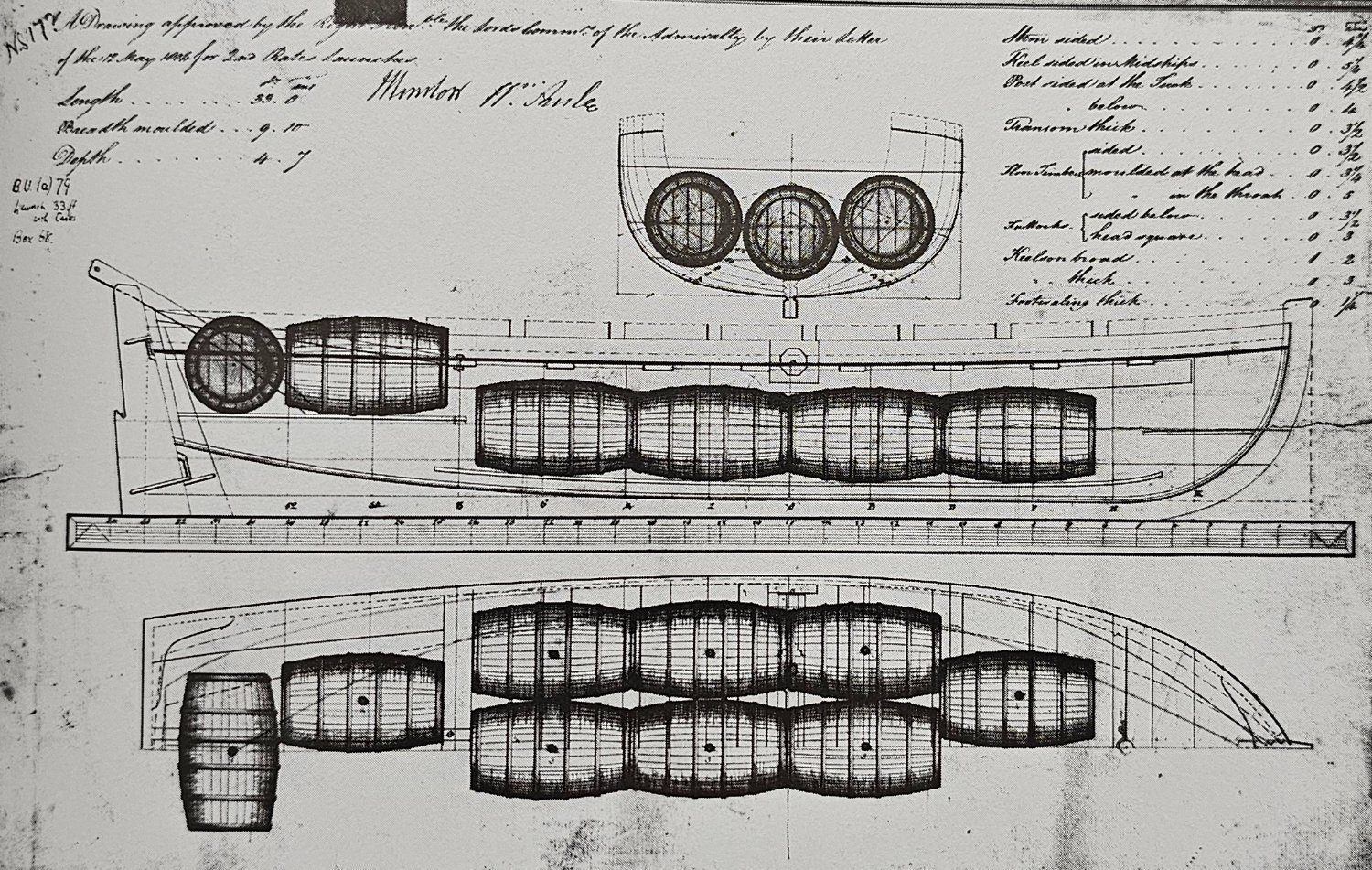
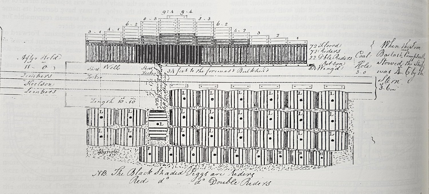
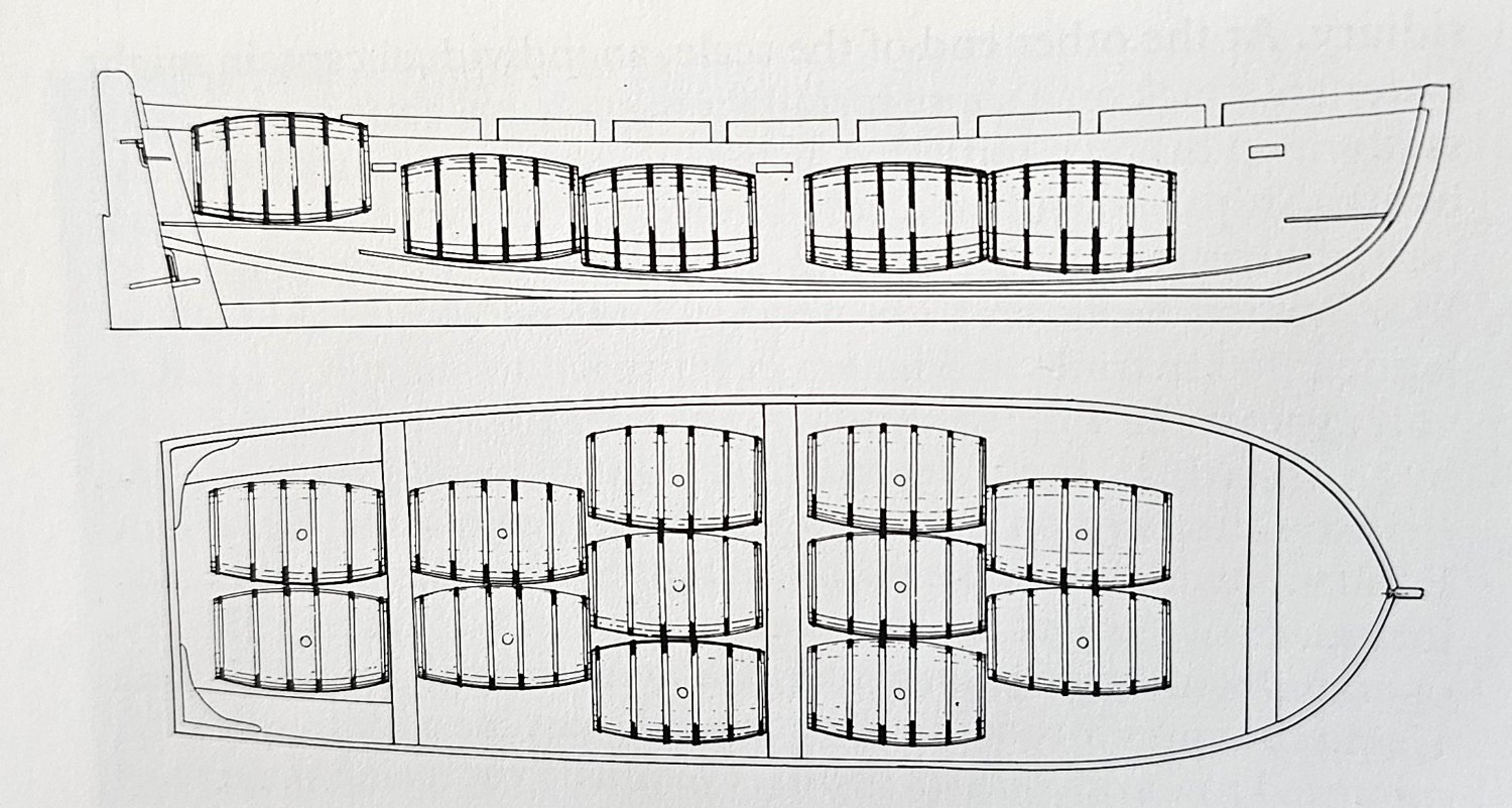
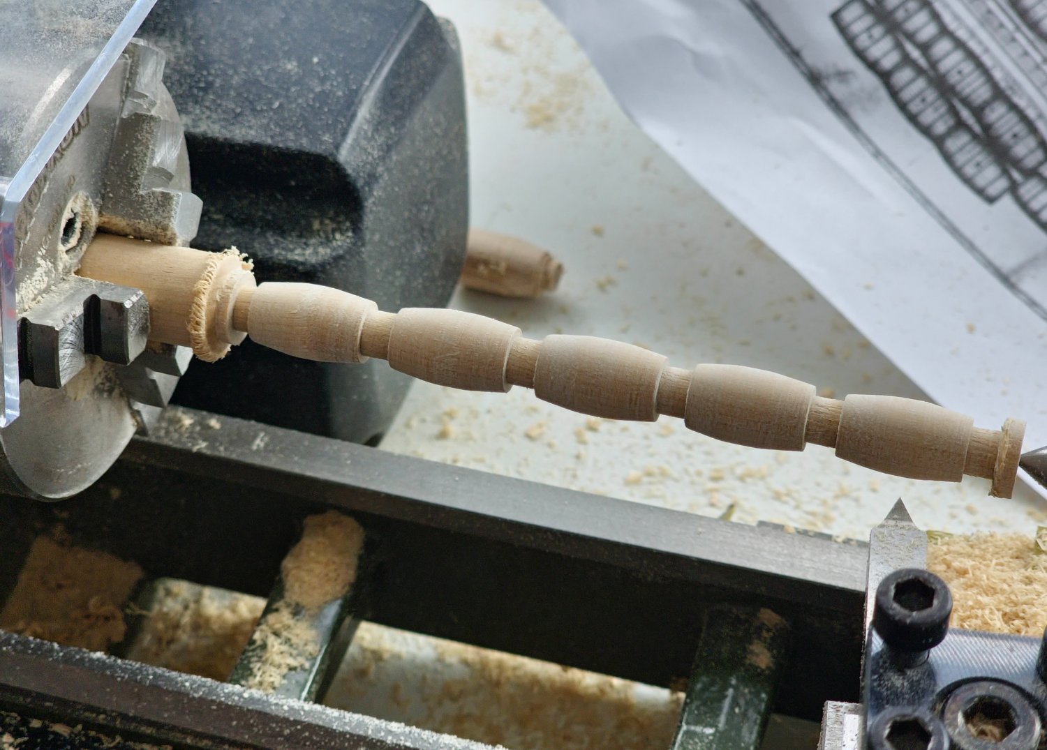
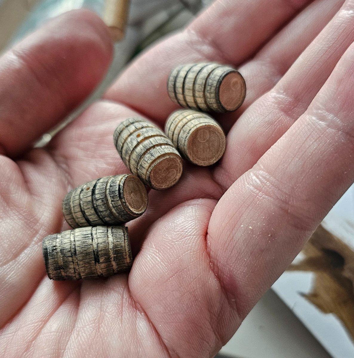
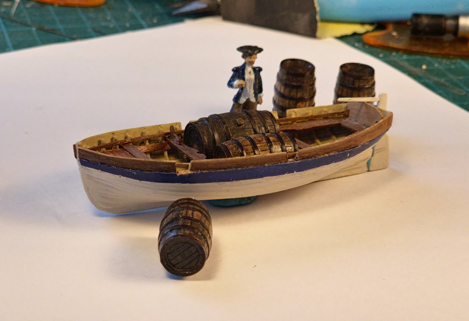
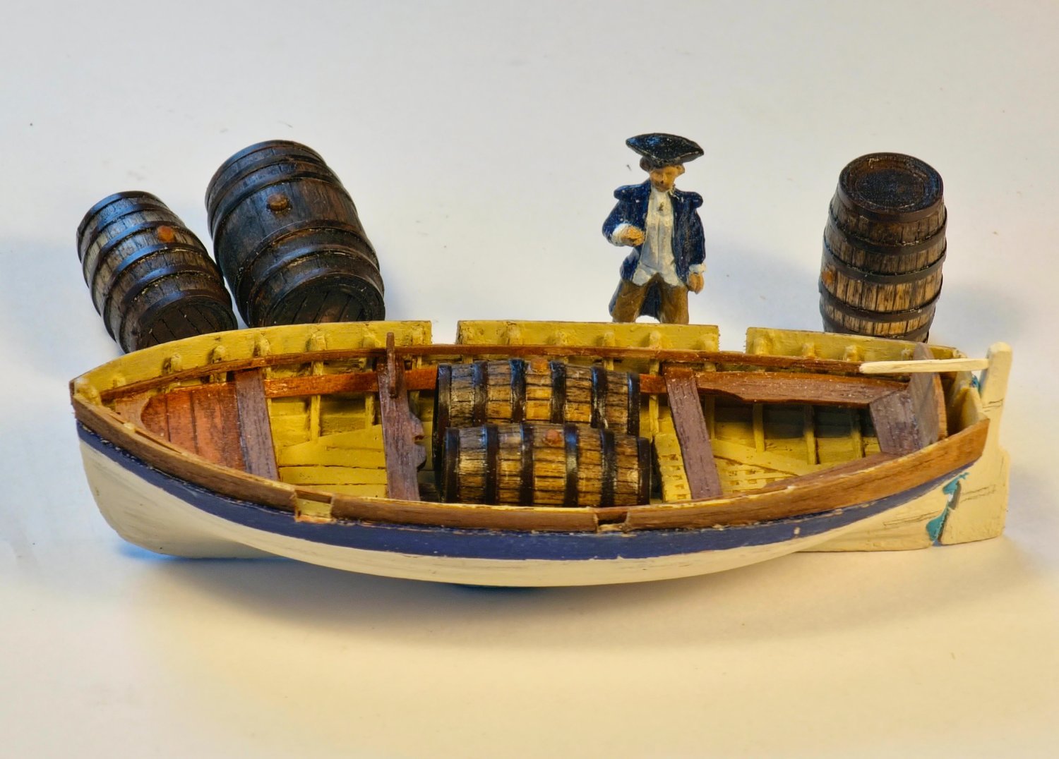
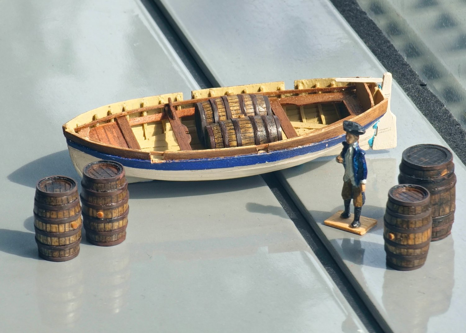
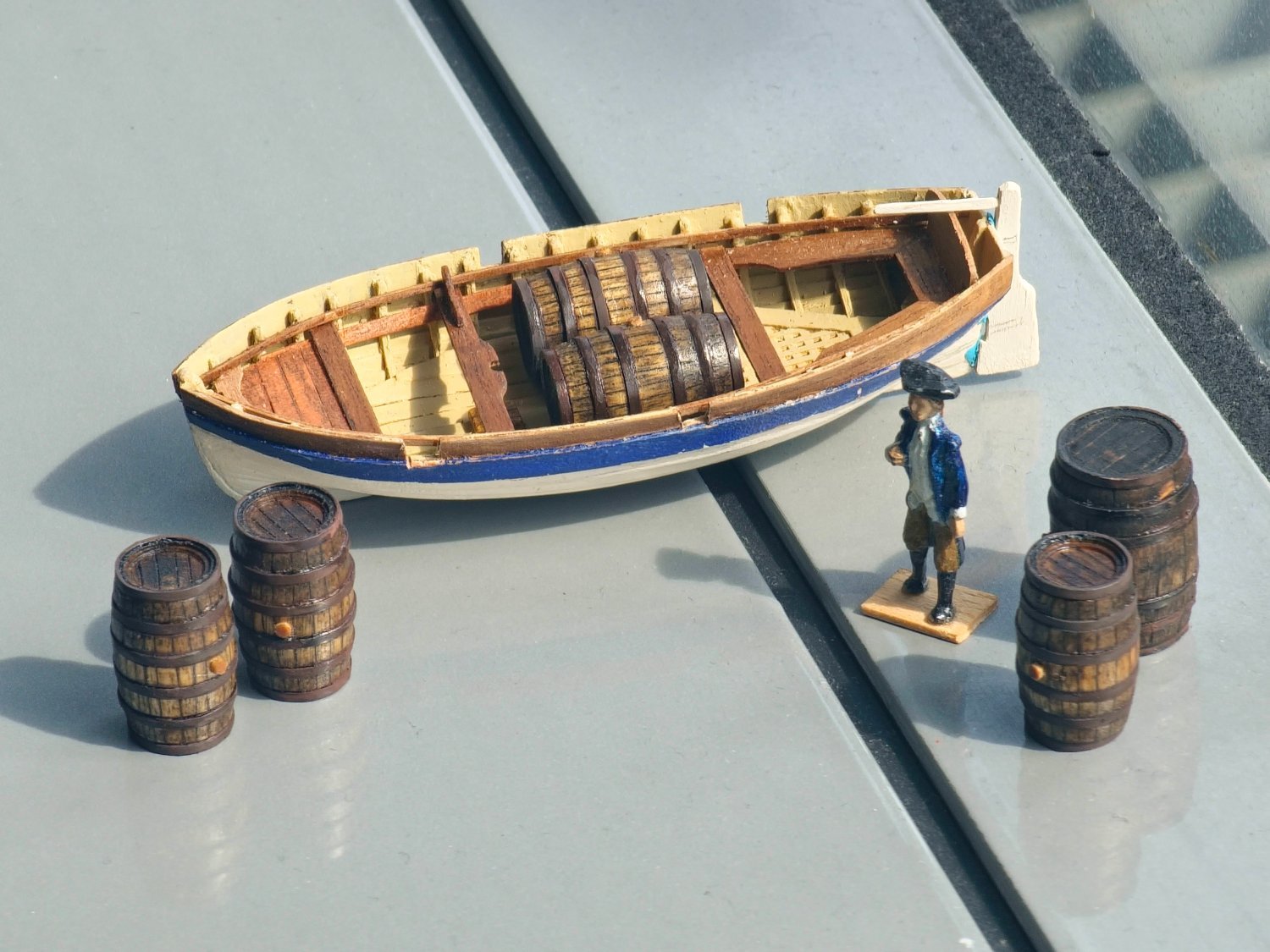
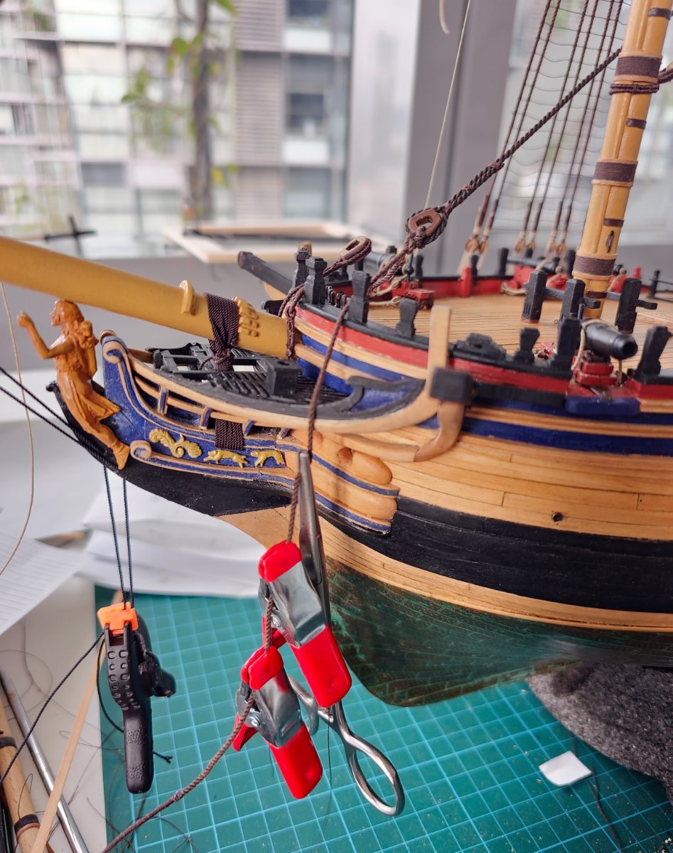
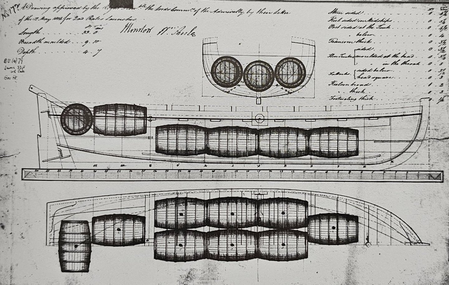
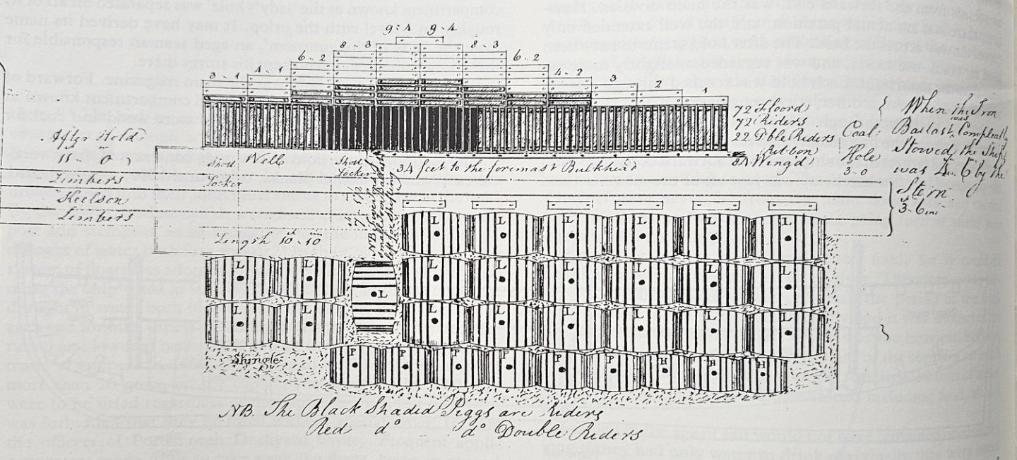
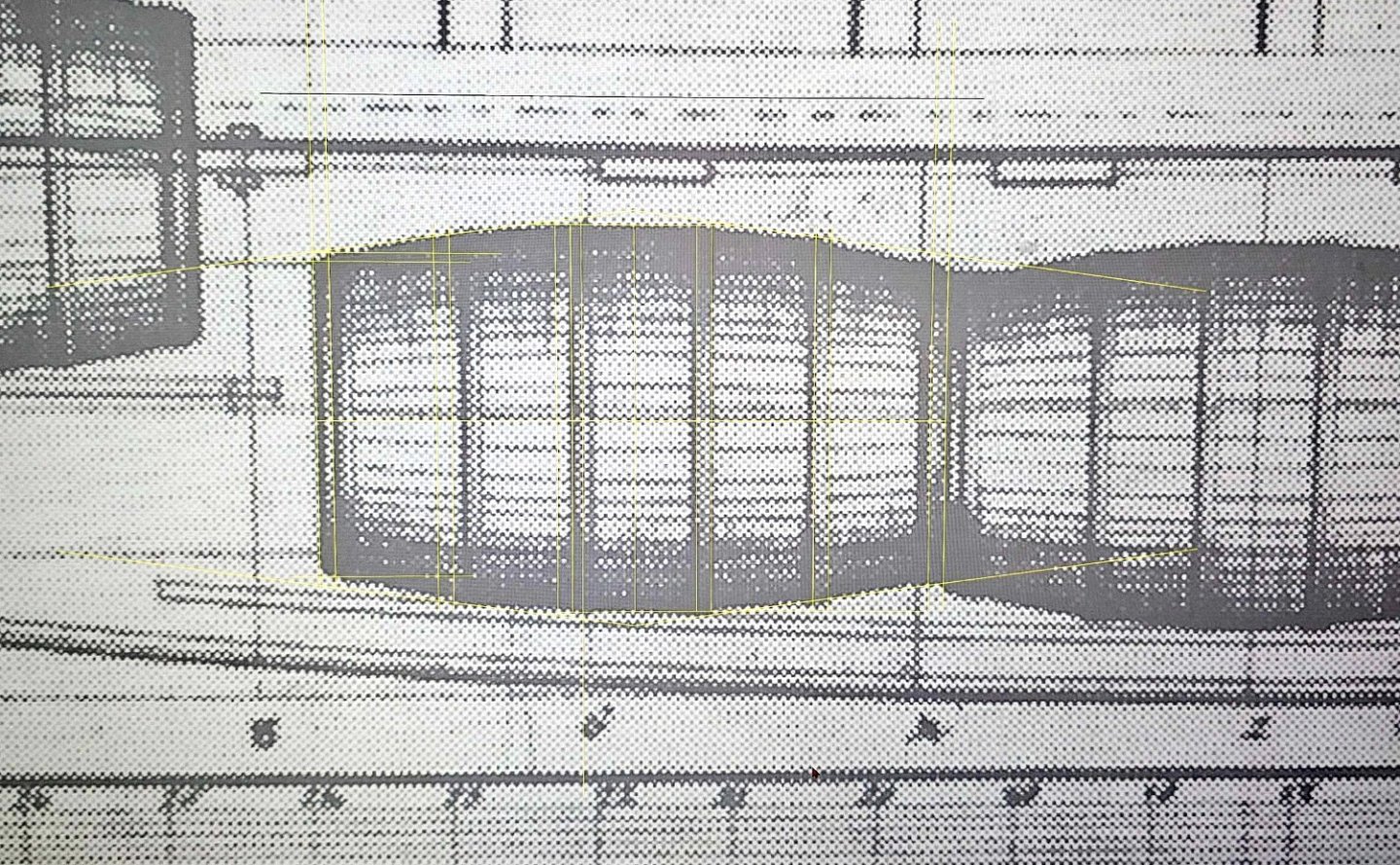
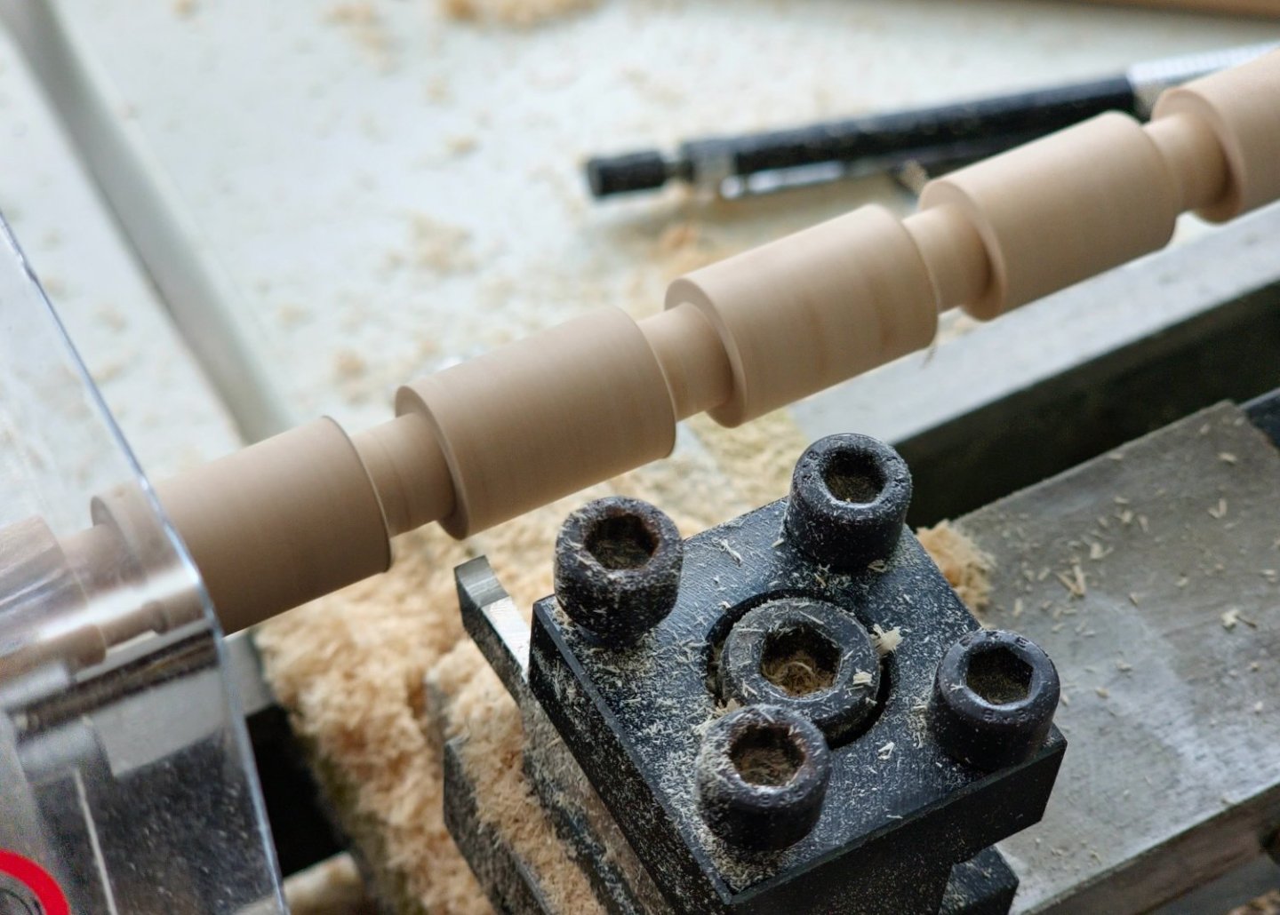
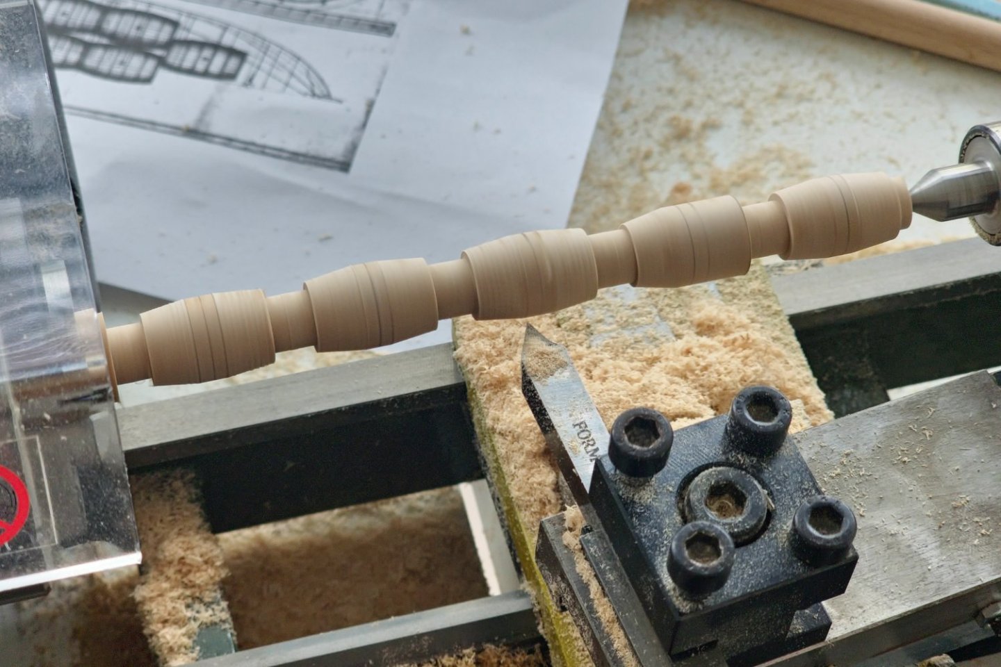
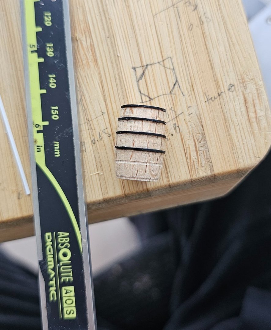
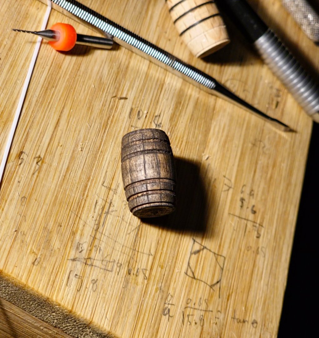
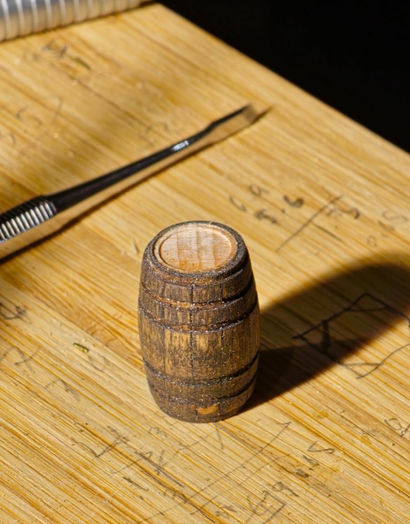
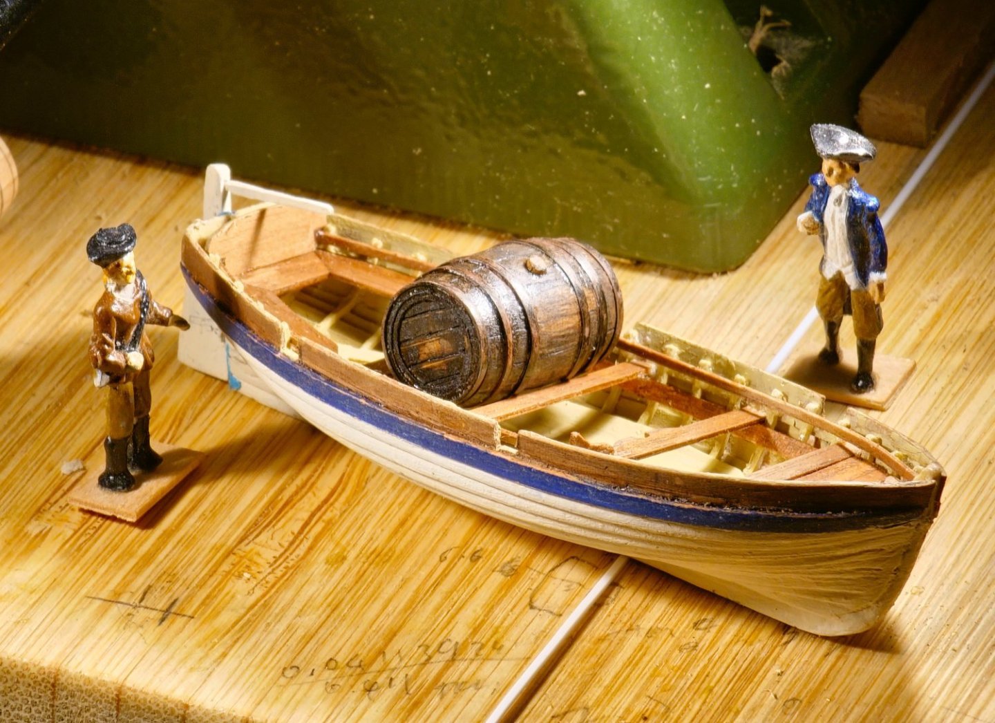
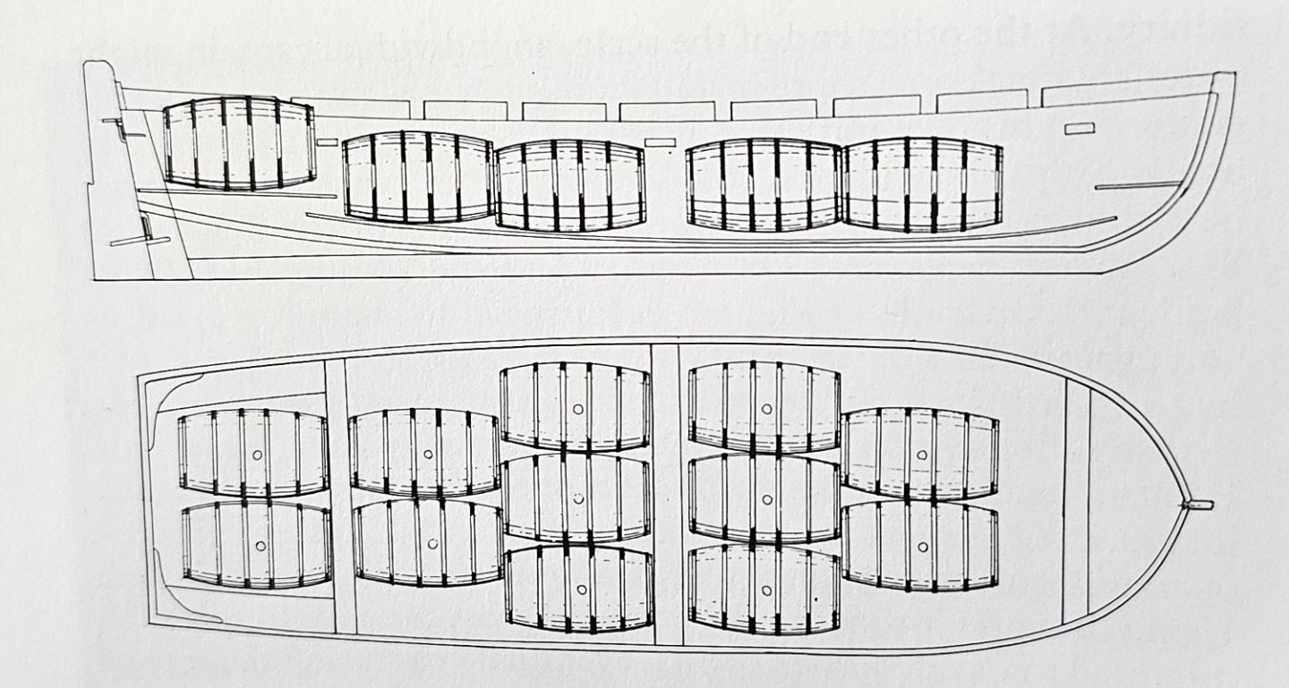
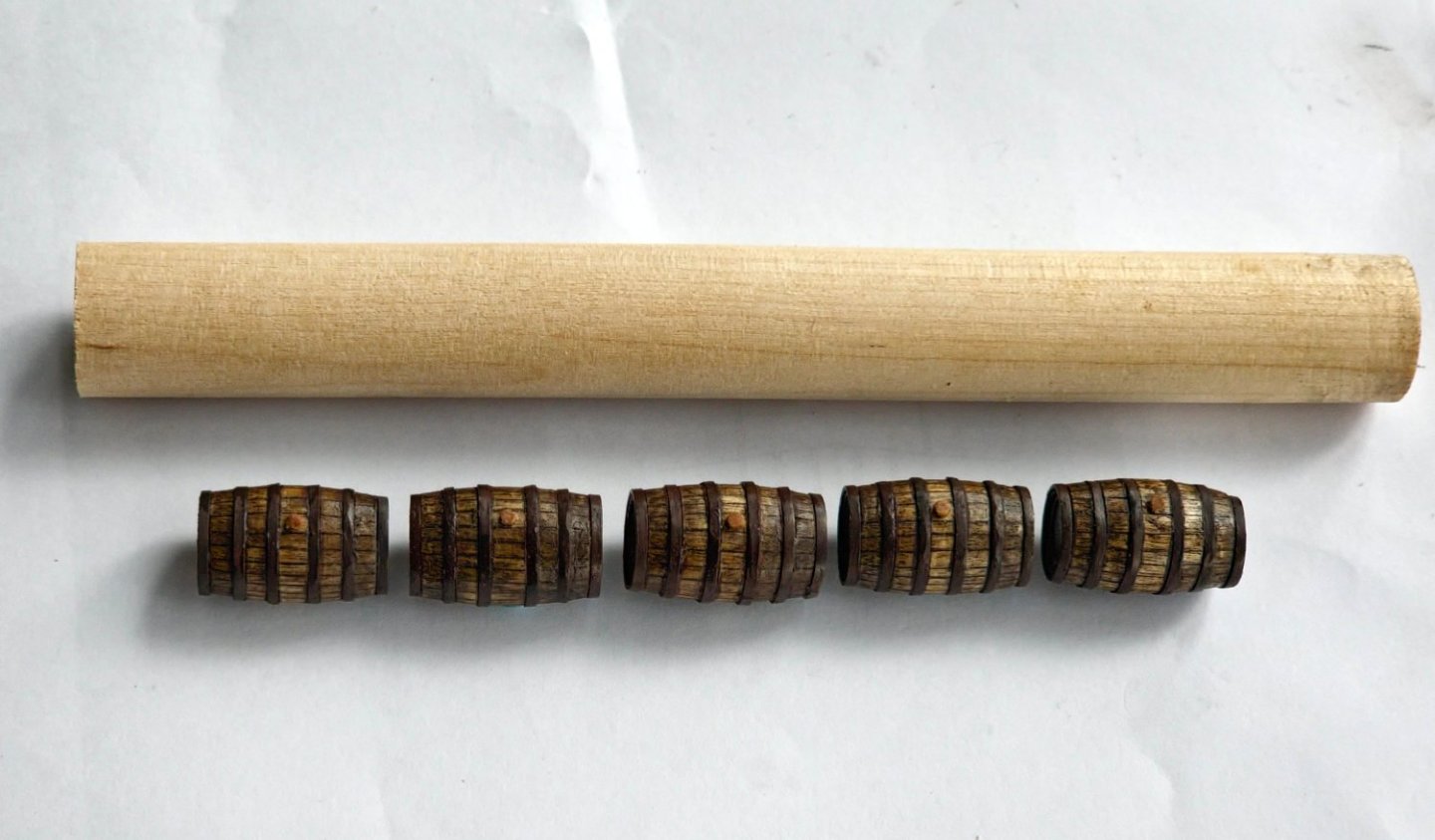
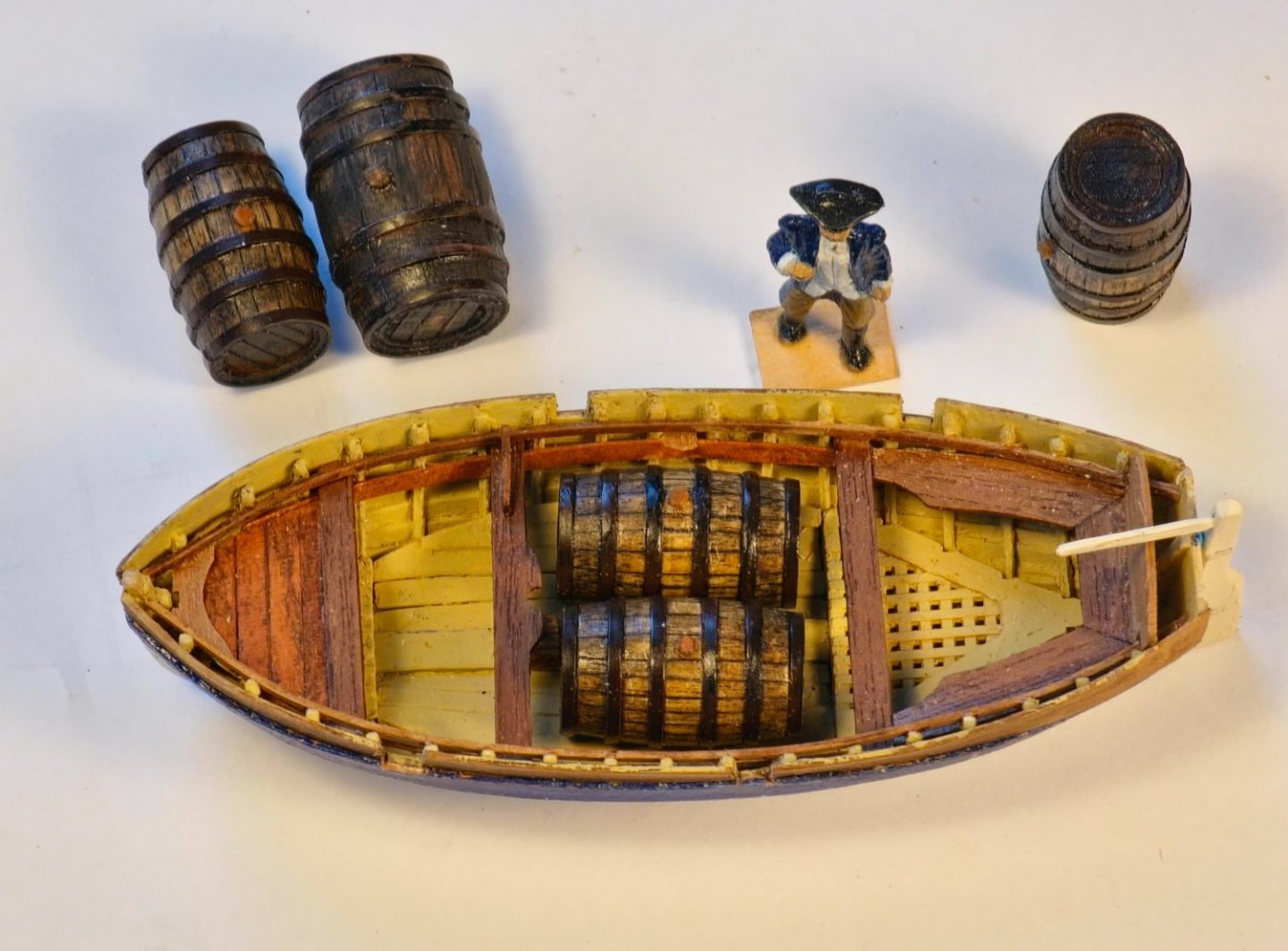
Not much of an update but after idling my time away playing with the printer and then doing nothing for a month, I felt in need of building something using tools. Nothing too ambitious mind you which ruled out the yards. I had a notion to display one of the ships boats being hoisted aloft in the rigging as though it was being launched. If I did, I thought I should include some cargo for added interest. A few barrels sprung to mind as the ship’s boats were often used to ferry barrels ashore to be replenished with fresh water. Lavery notes that the ships were provisioned with 6 month’s worth of food but only 3 months of water meaning the captain would have to stop off near some handy water source to fill up his barrels. May has a copy of a contemporary drawing showing a 33ft launch filled with 14 leaguers. These are the largest standard barrel carried and have a capacity of 150 gallons. I have often wondered why only some thwarts have knees and it seems that those without are removable to allow the loading of cargo. The whole arrangement looks somewhat like a theoretical maximum as I cannot imagine it would be all that easy to pilot that boat through heavy seas with that amount of cargo. At least it gave me a dimension for the barrel which was a start. Lavery has a handy contemporary drawing showing the placement of casks in the hold of the frigate Artois, sister ship to the Diana. This shows that it did indeed carry leaguers and confirmed the dimensions shown in May. Given the leaguers dimensions of 4ft. 6in. height and a diameter of 3ft. round the middle I started off with a 15mm diameter beech dowel. This was inserted in the lathe and then reduced to a 14.2mm diameter and divided up into five 21.4mm sections in the hope that I would get at least one barrel out of the five. I then bevelled the ends at 7.85 degrees. This was the first failure as the markings on the lathe that I thought were degrees turned out not to be. Angle corrected I proceeded with the rest. These sharp angles were then softened into a barrel shape with sandpaper. I scored lines along the length of the barrel using a scalpel to imitate the staves. There should be upward of 30 staves to a barrel but as the beech was quite hard, I only included 15 as it was tricky to accomplish and you are guaranteed to jab the scalpel into your palm every 12 or so staves. I milled out grooves to countersink the metal hoops which I made from styrene strip painted black. A recess was milled in the top and bottom to simulate the lid and I rubbed charcoal dust into the stave grooves to give them more prominence. I gave the barrel a stain of walnut and stuck in a cut off toothpick for the bung. Once it was placed into the Jolly boat prototype the crew were heard to comment that they needed a bigger boat. There is a drawing in Lavery that shows a layout of a launch carrying 12 of the smaller butts which are only 108 gallons. They note that a first rate launch can carry 14 butts but a third rate only 12. I decided that perhaps butts were the way to go. I found a table in Steel where he gives the overall dimensions of the various types of casks stored on a ship so I used these for the smaller barrel which turned out to be 20.6mm in length and 12.9mm diameter around the middle. As the beech dowel was quite hard to work with, I used a different wood for the butts. I found it in a drawer so I do not know what the timber was but it was a lot softer. Probably too soft. It was easier to score the grooves for the staves though so I increased the number to 24. The barrel was made pretty much the same way as the leaguer but I used a smaller styrene strip for the metal hoops. I really needed something a bit smaller and thinner but they do not seem to make strip of the dimensions I required and cutting them out of larger sheets proved to be too frustrating and inconsistent. The end result was a bit shaky but sat more comfortably in the Jolly boat so should be even better in the launch if I ever get round to building it. I do not think that twelve casks would be all that practical though and a rough measure with the scale rule would seem to suggest that six is crowded enough.


-
Well done David. It is an impressive addition to the room. I like the way you have incorporated your reference books into the display. Your build log has proved very to me as it has to others I am sure. Regards, David
- 310 replies
-
- 2
-

-
- Diana
- Caldercraft
- (and 1 more)
-
Thanks JJ. I am quite impressed by the level of detail you can get out of these machines. It is a bit like airbrushing though. Good results but you end up having to do a lot of equipment cleaning afterwards. Regards, David
-
Thanks for the reassurance Chris. There was one unit left in the shop and I saw another customer making a beeline towards it so I quickly bought it as I did not want to go home empty handed. Regards, David
-
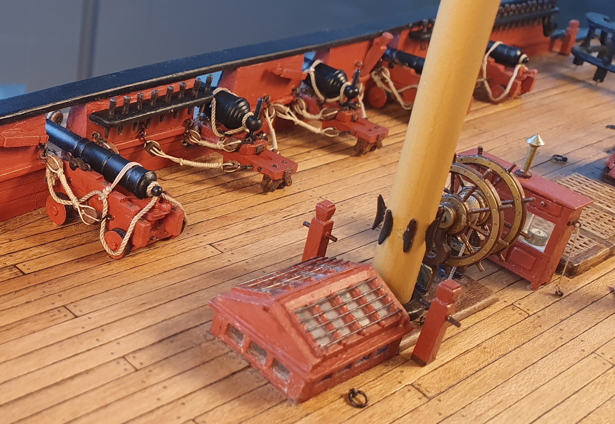
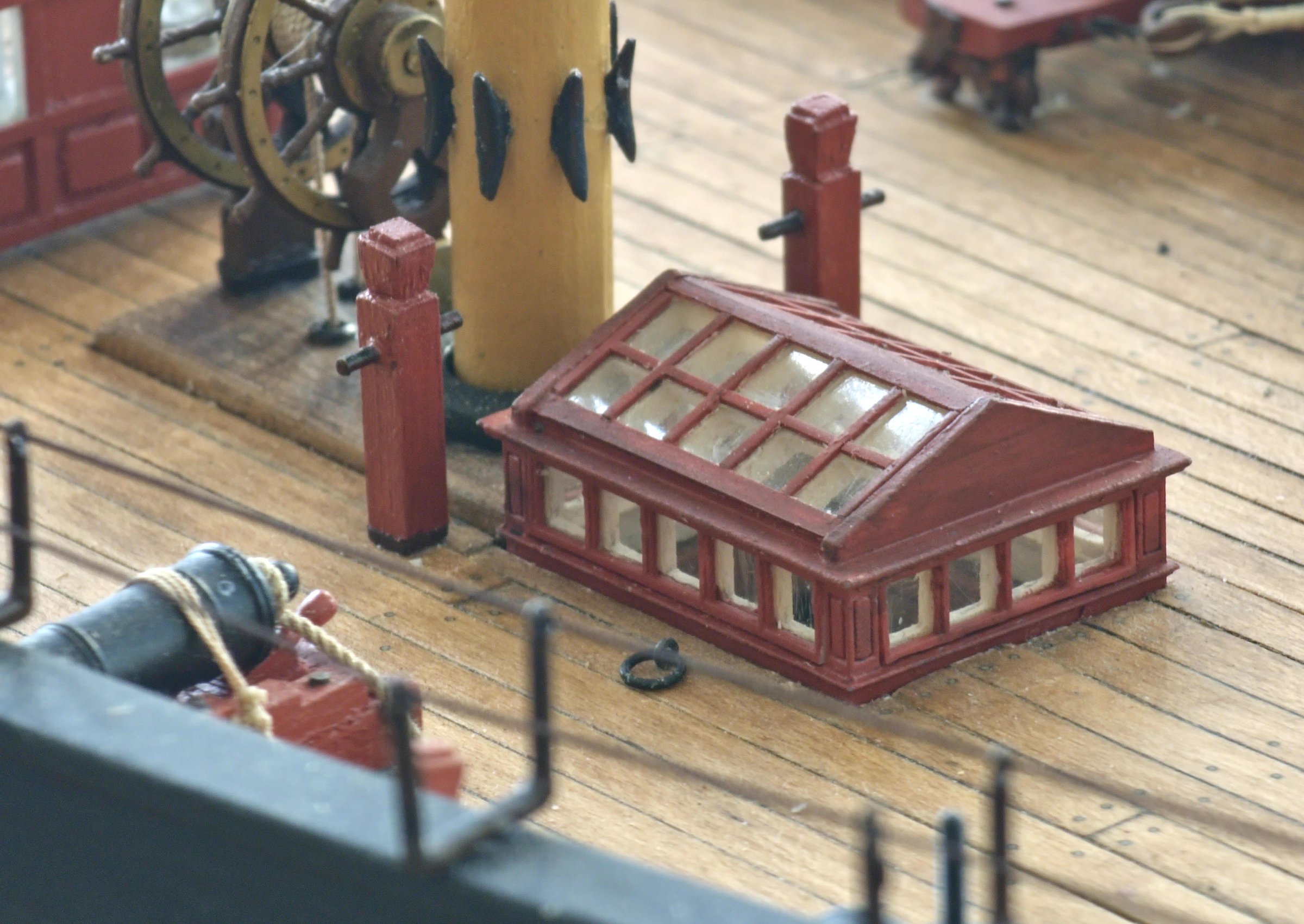
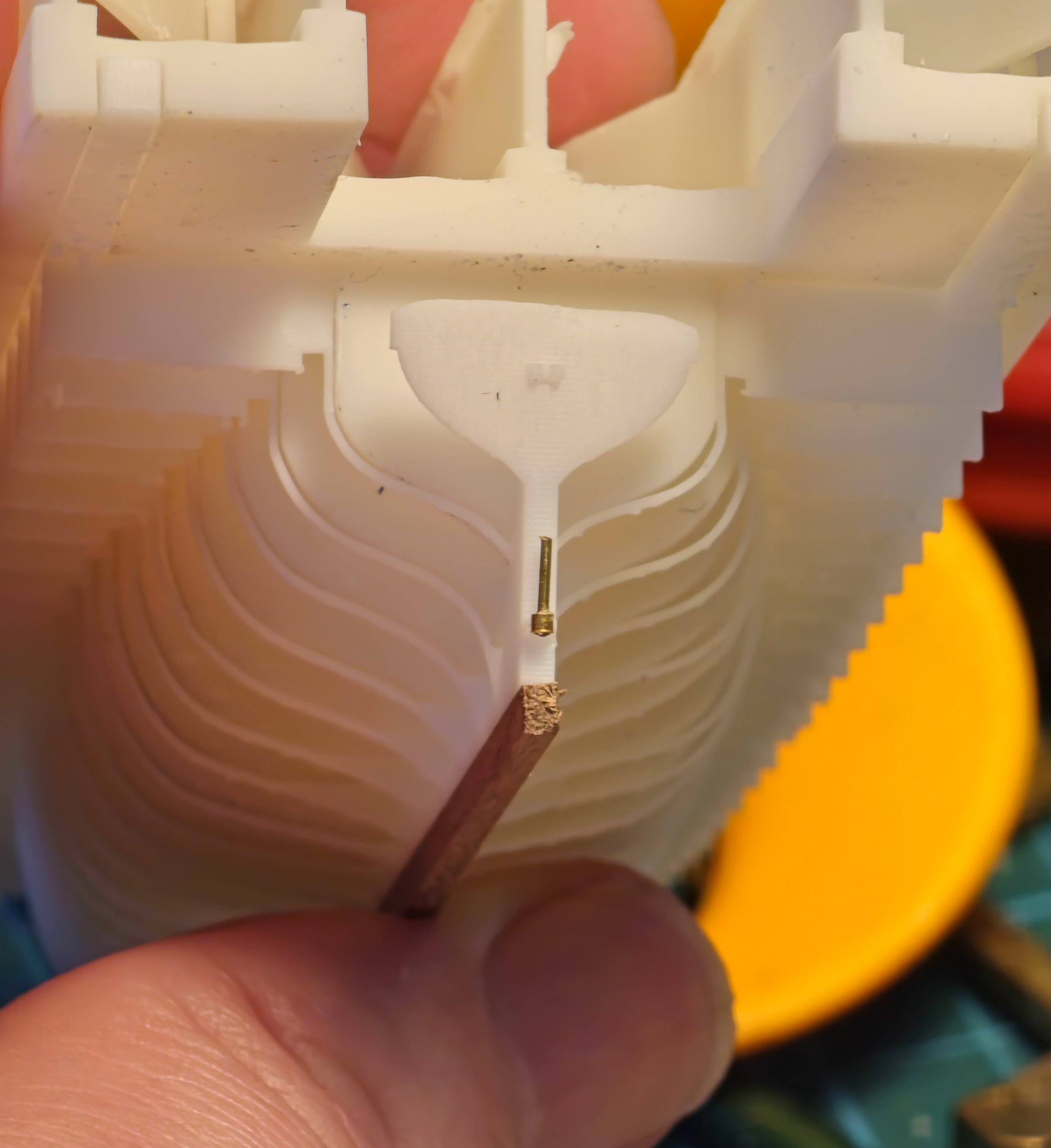
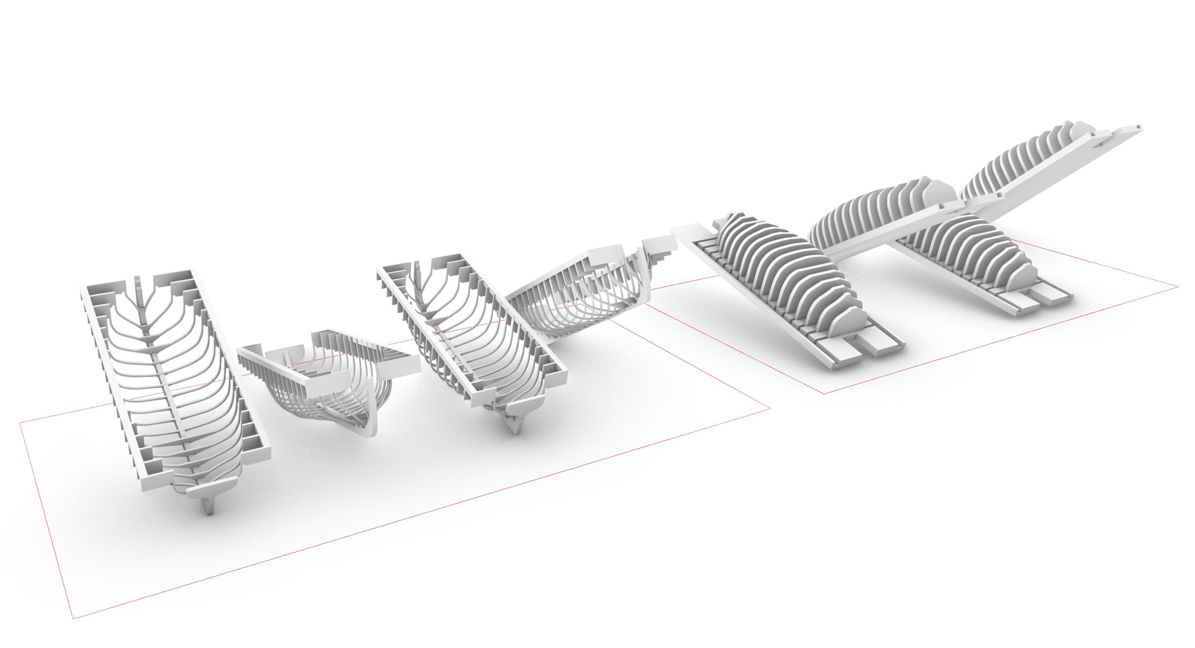
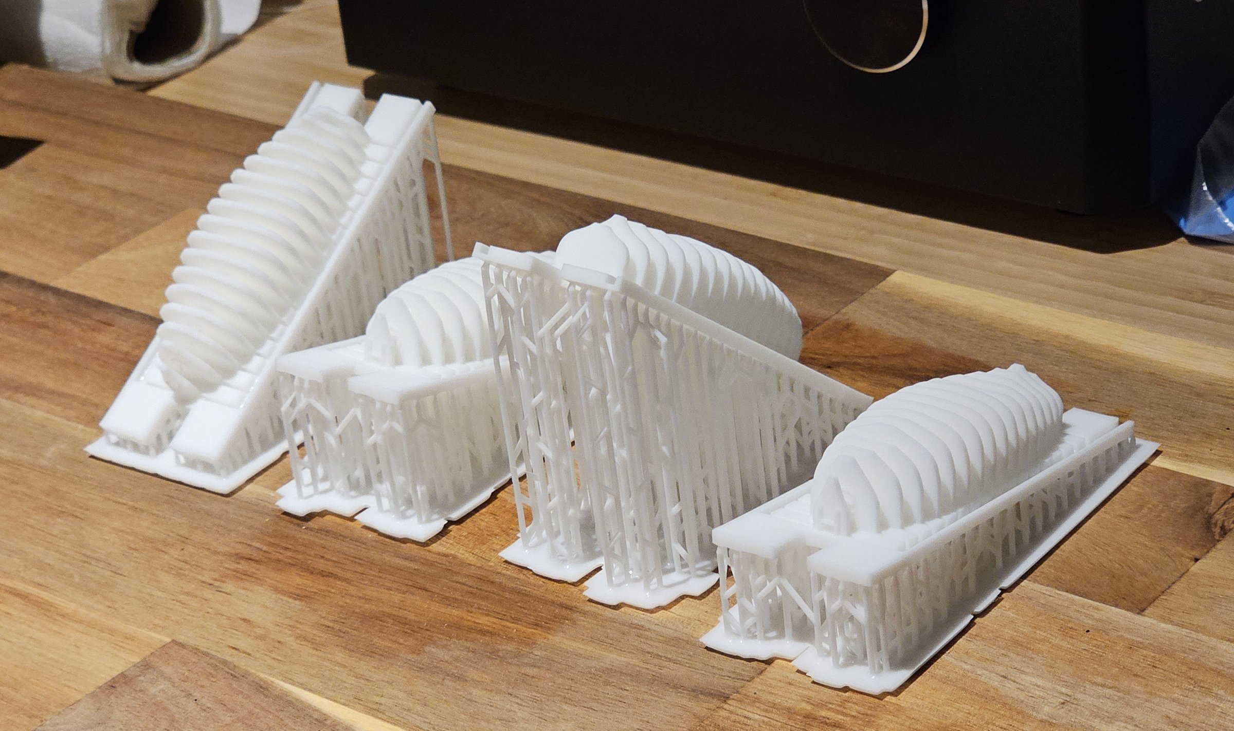
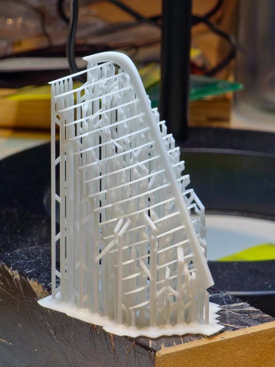
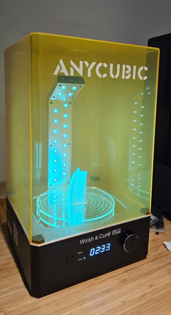
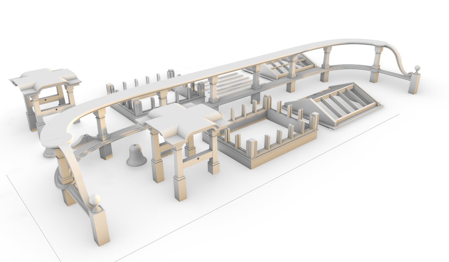
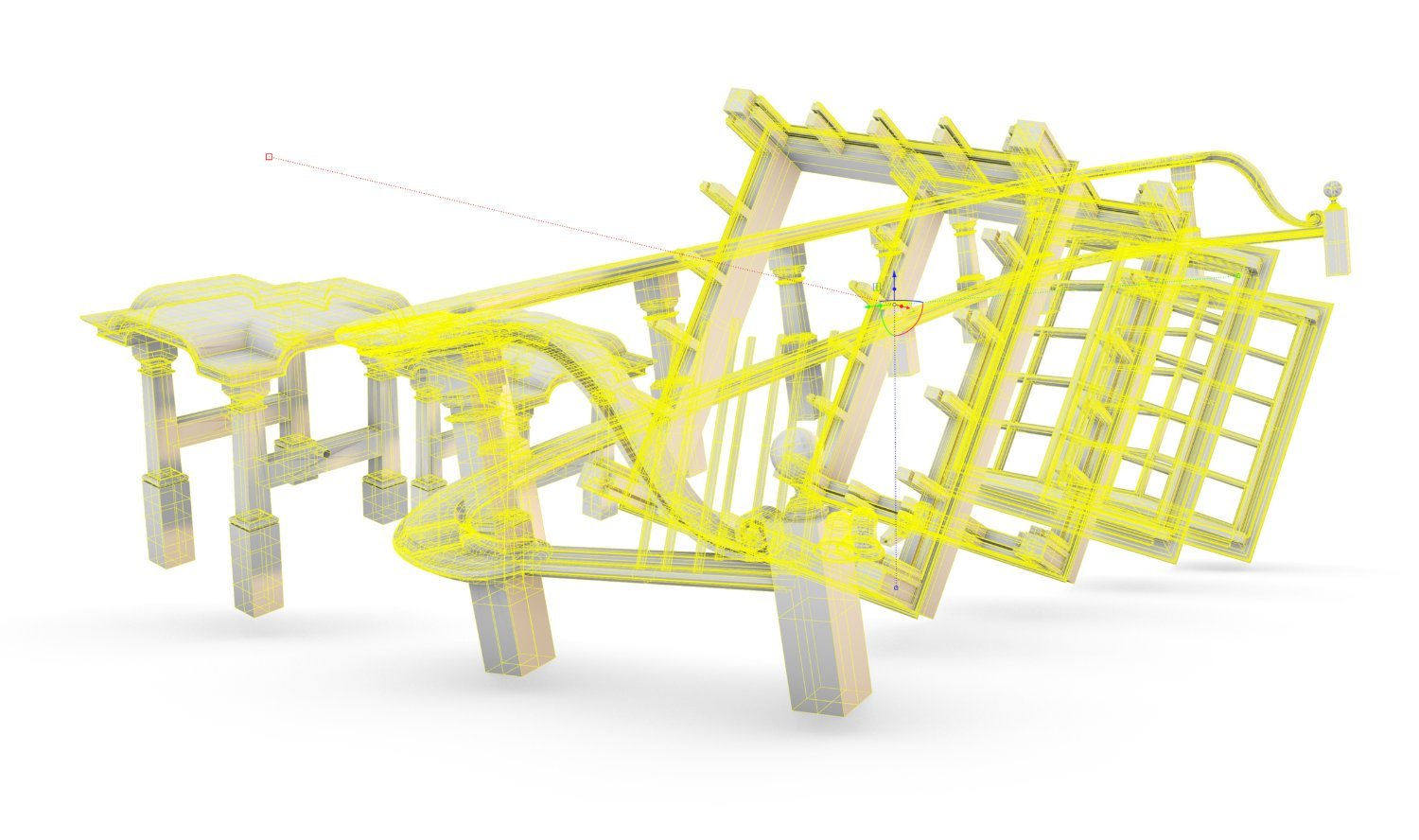
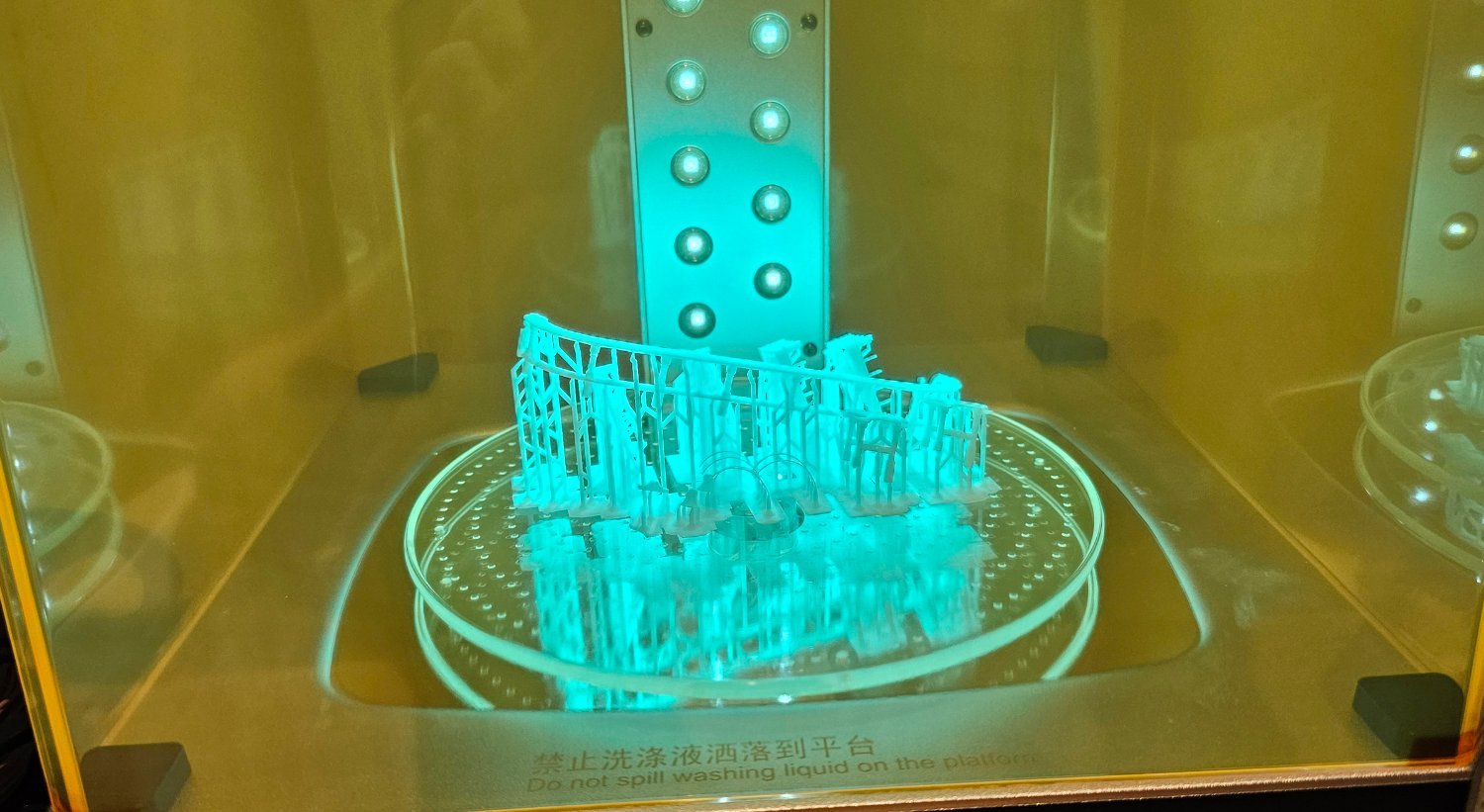
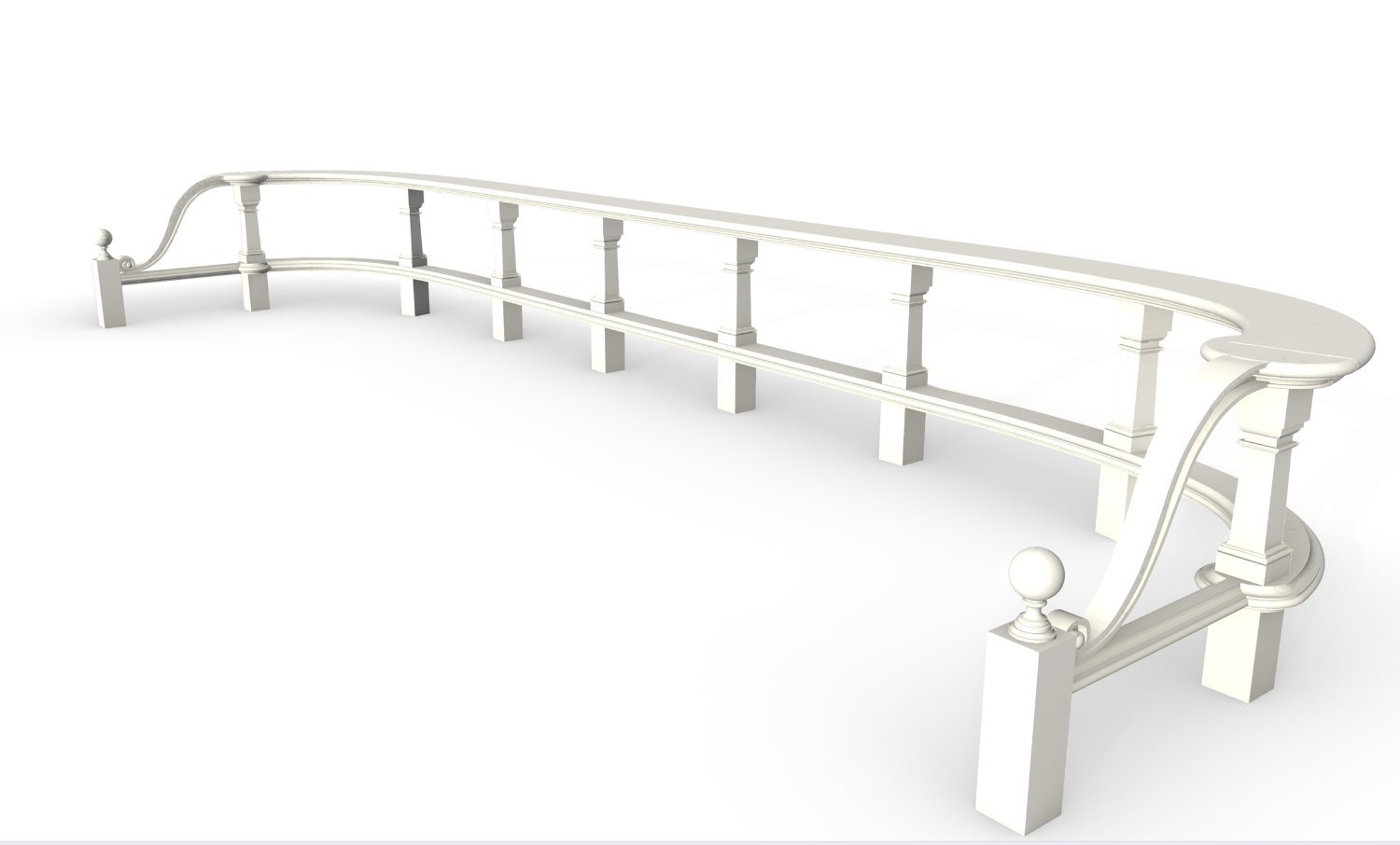
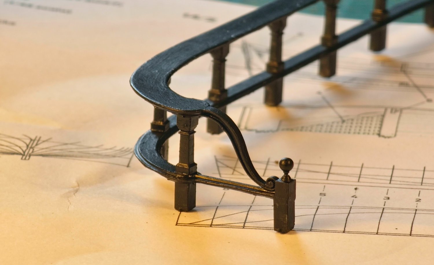
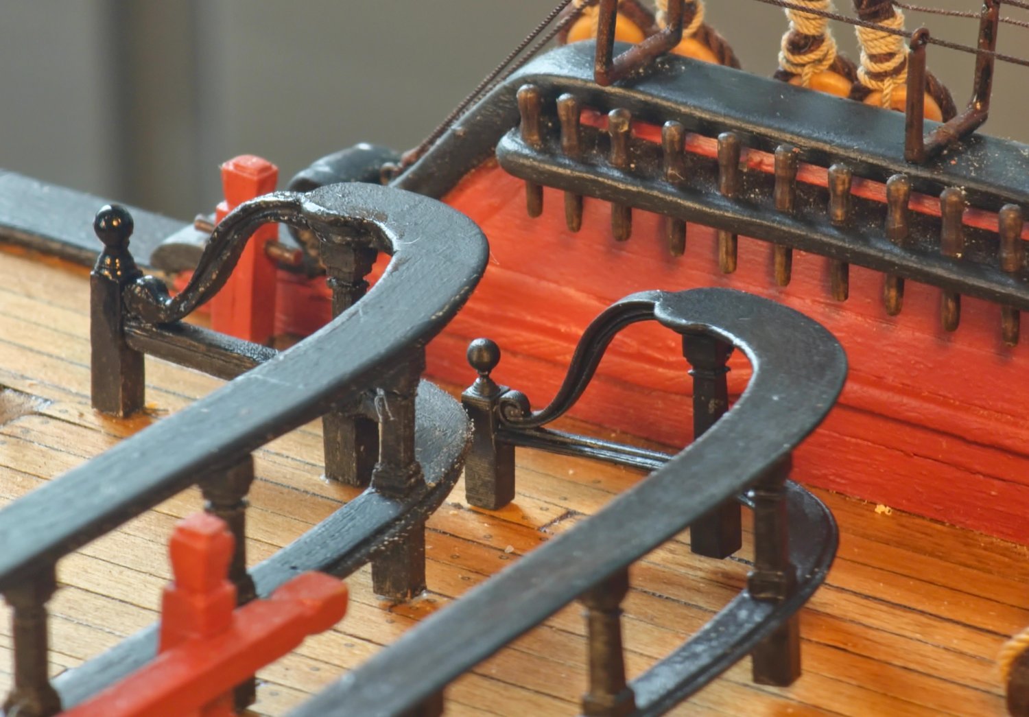
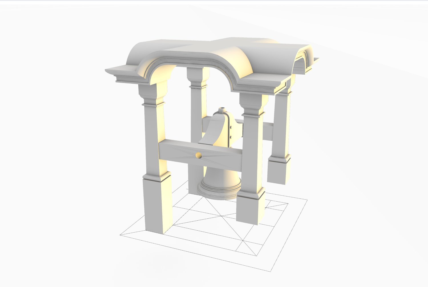
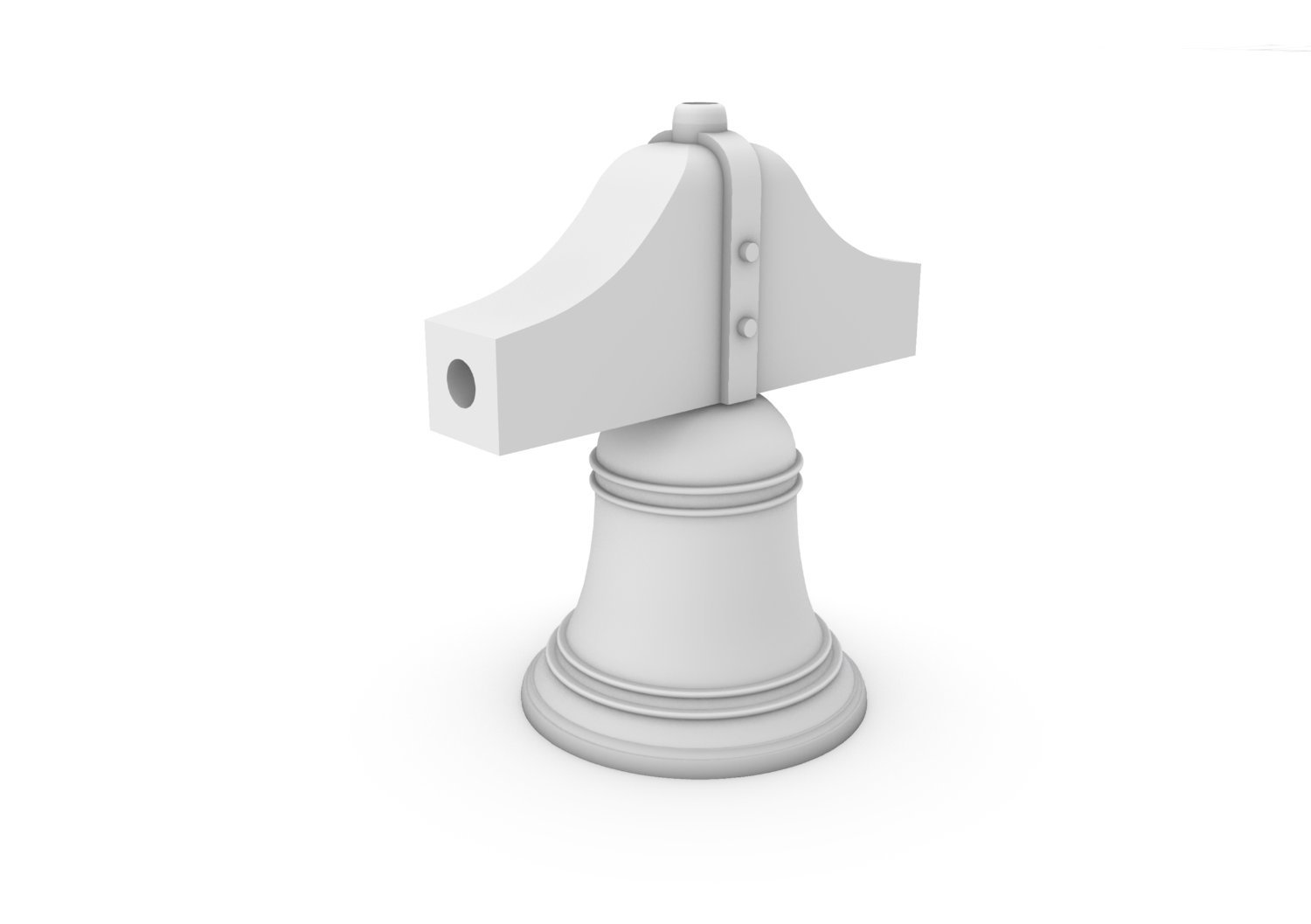
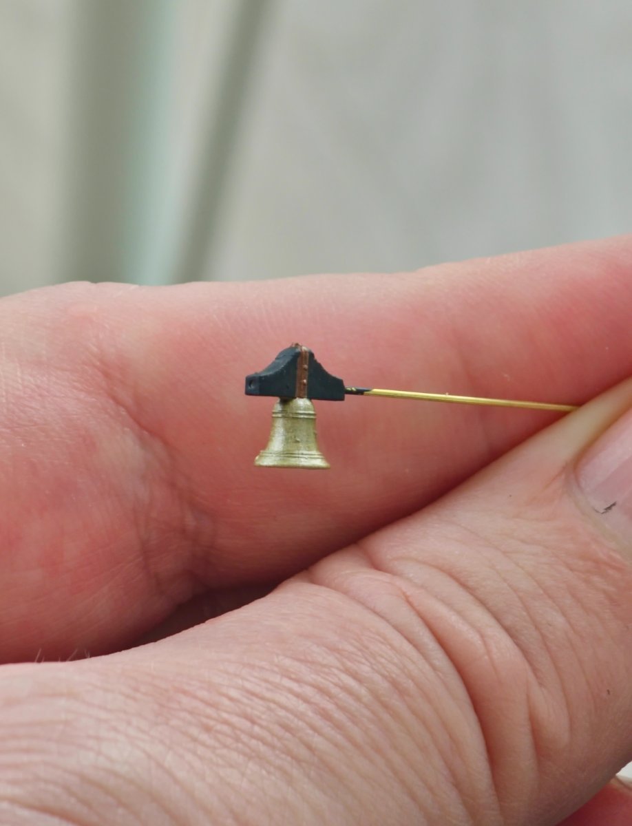
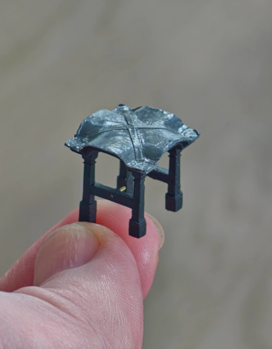
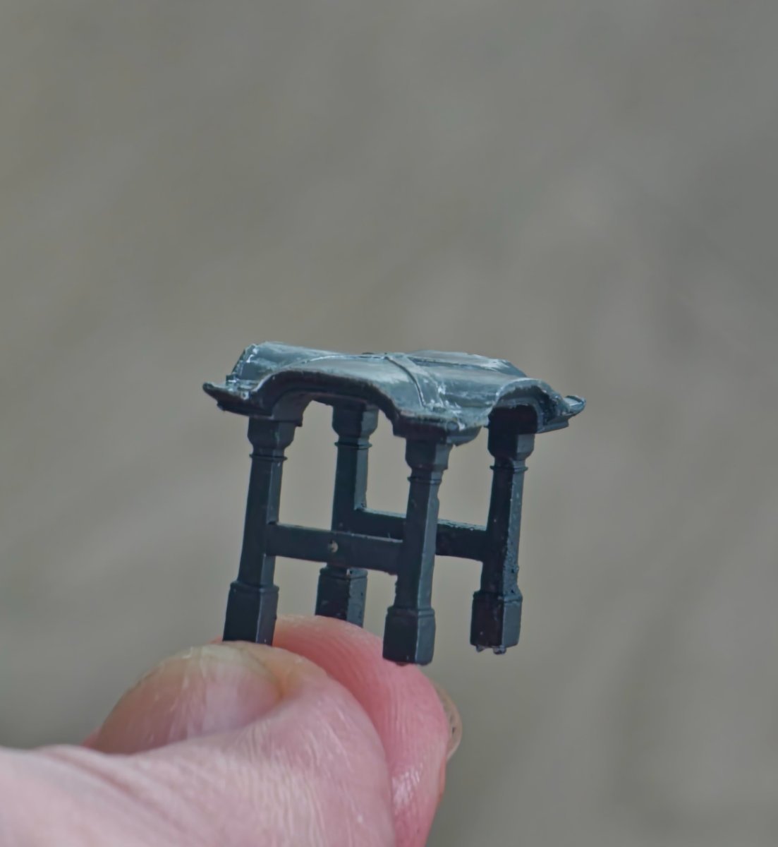
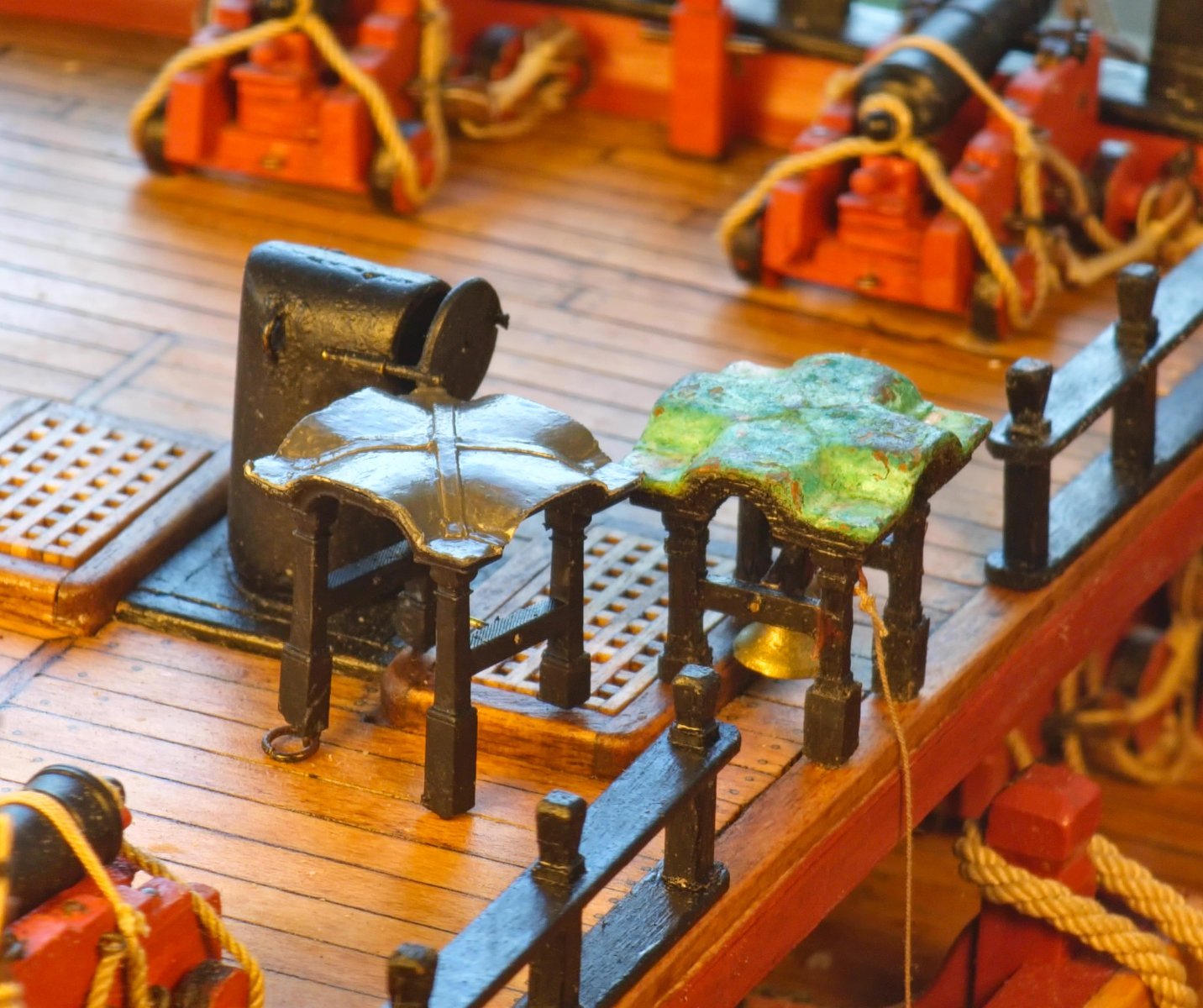
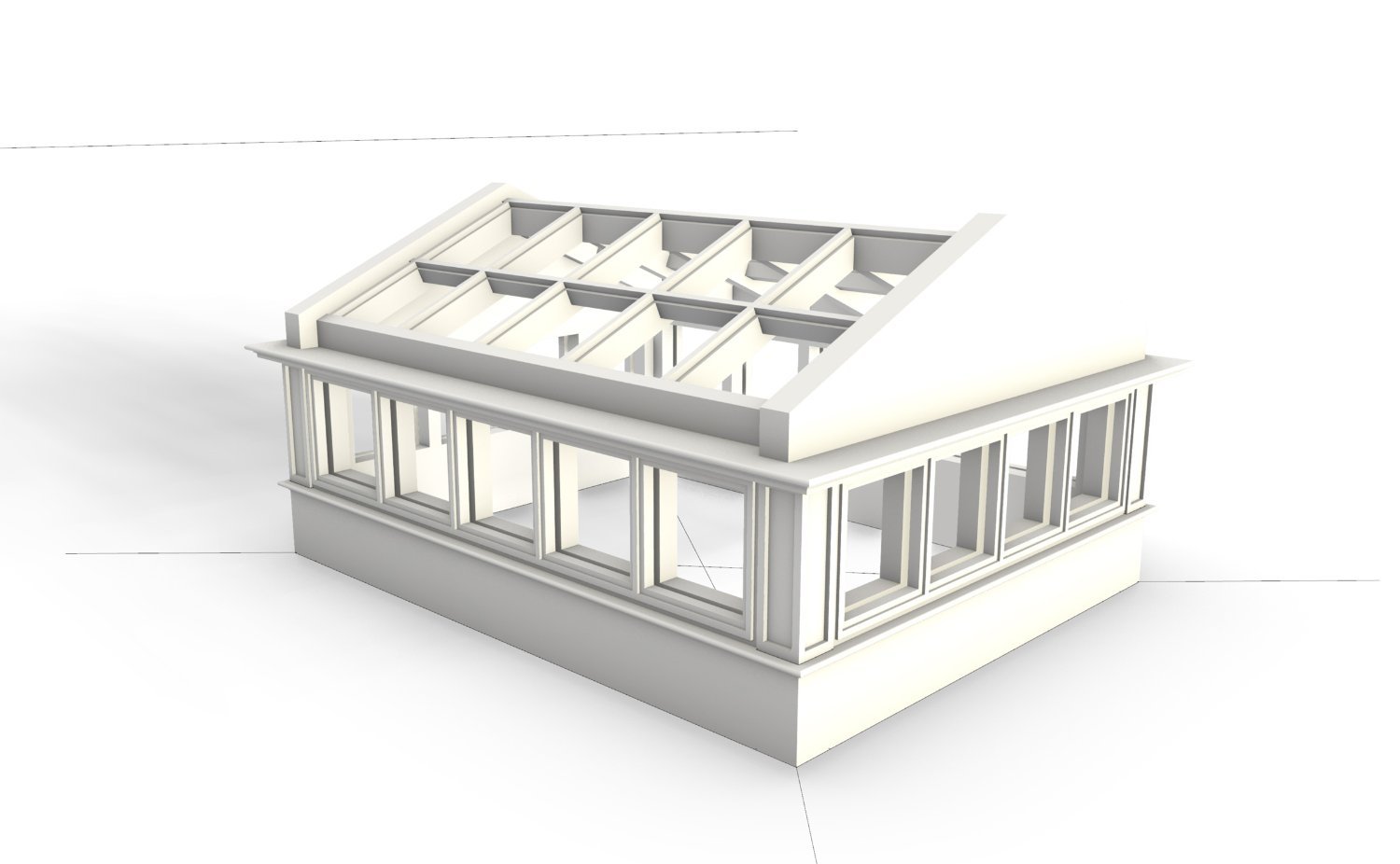
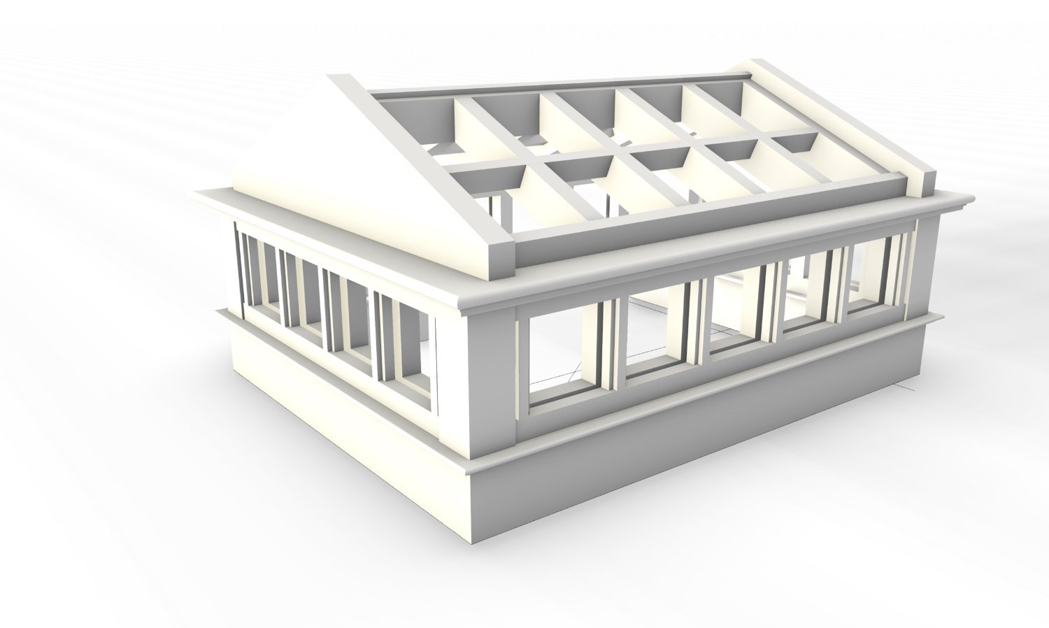
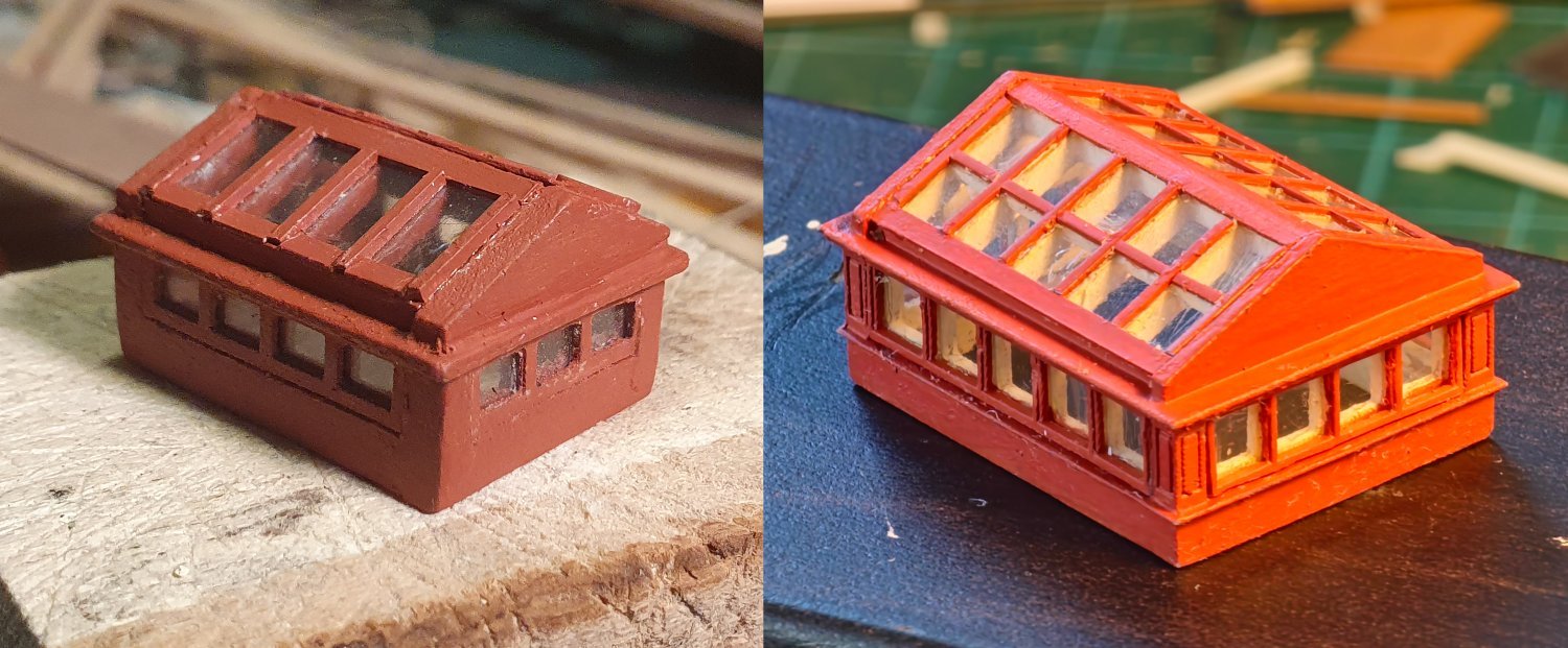
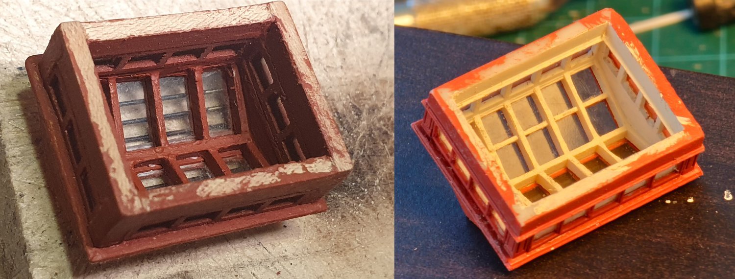
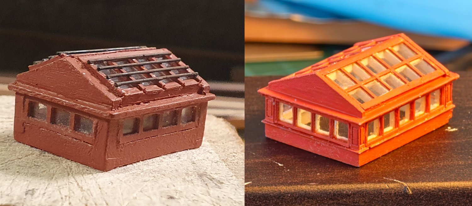
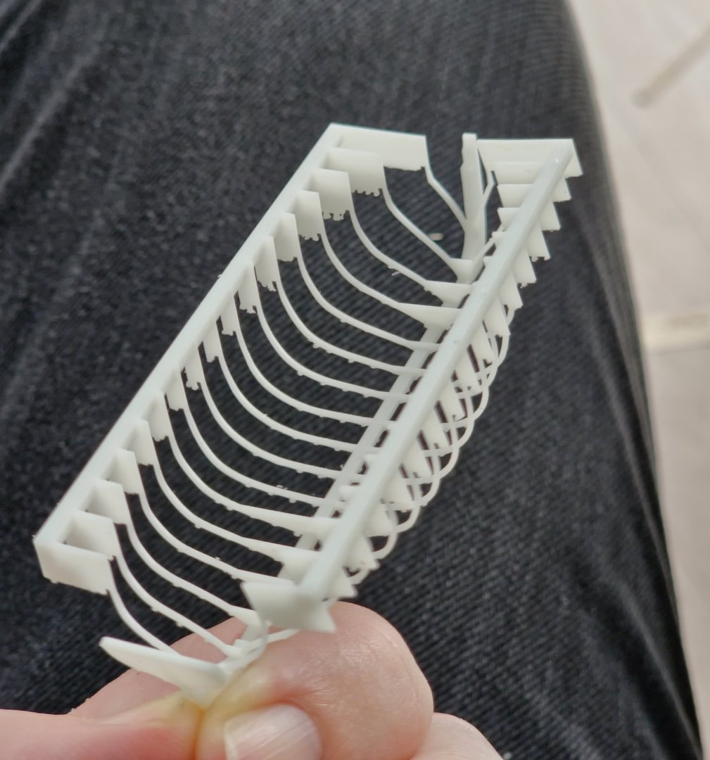
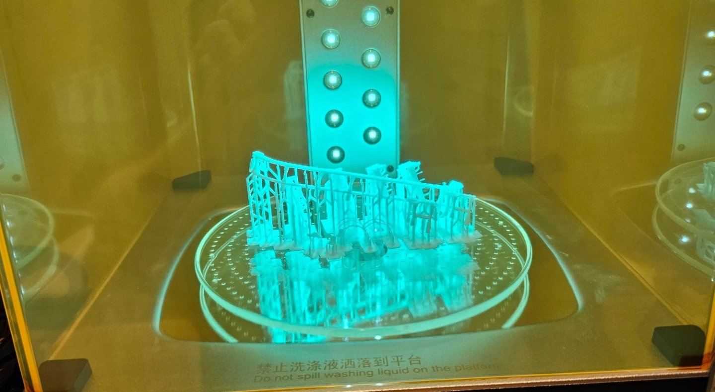
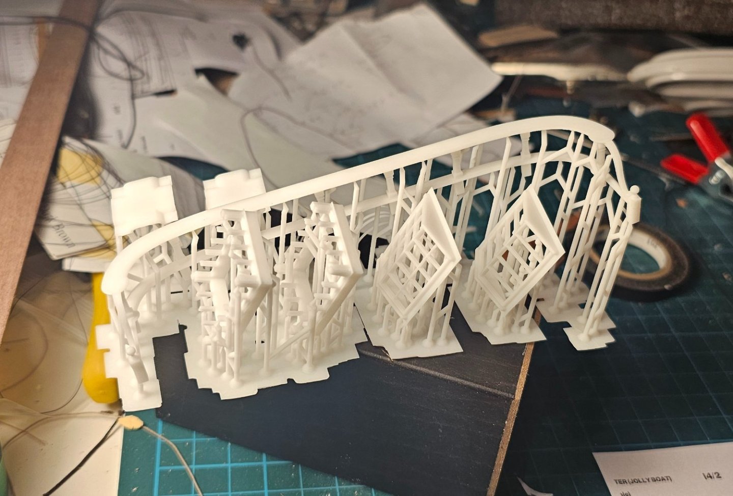
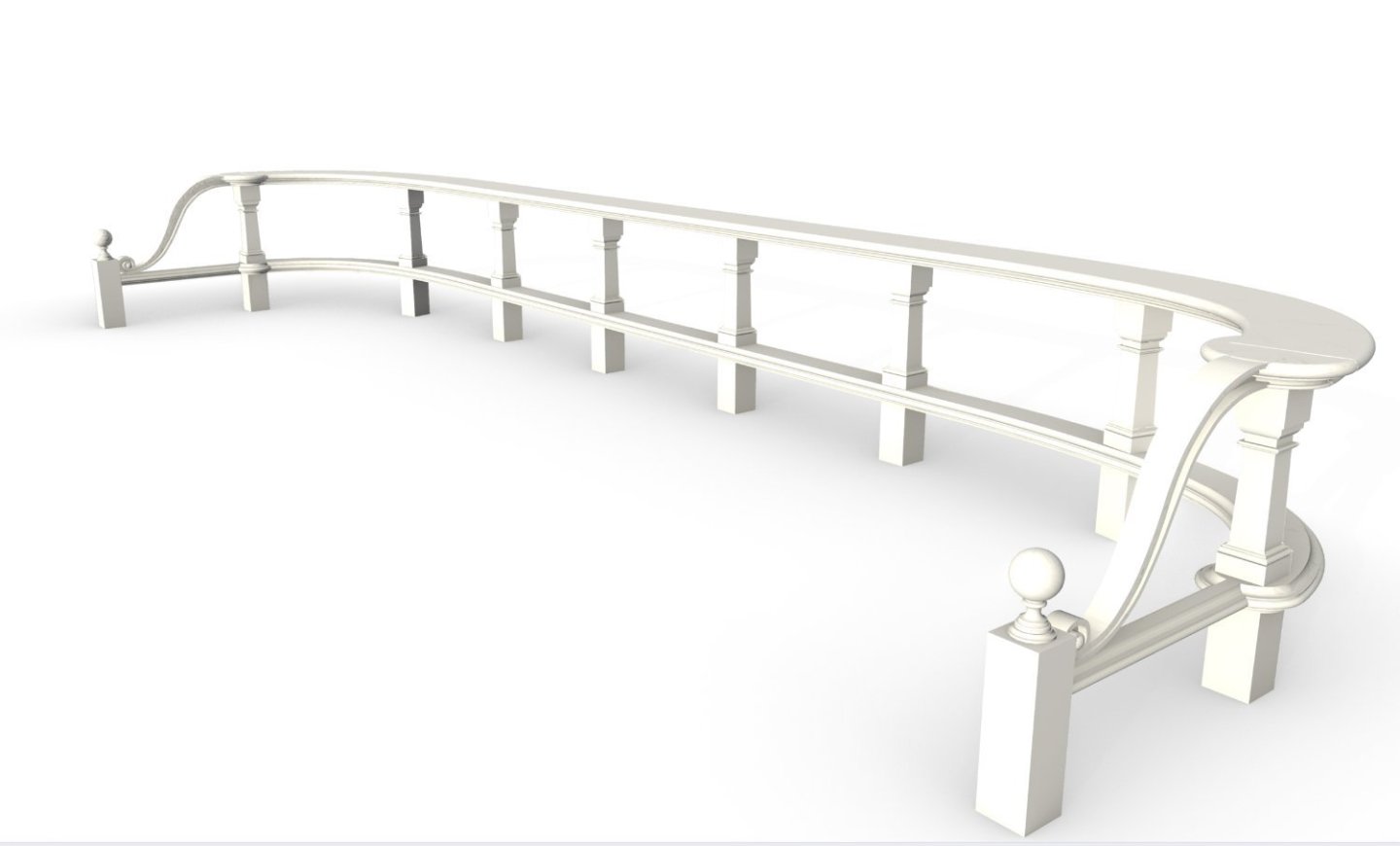
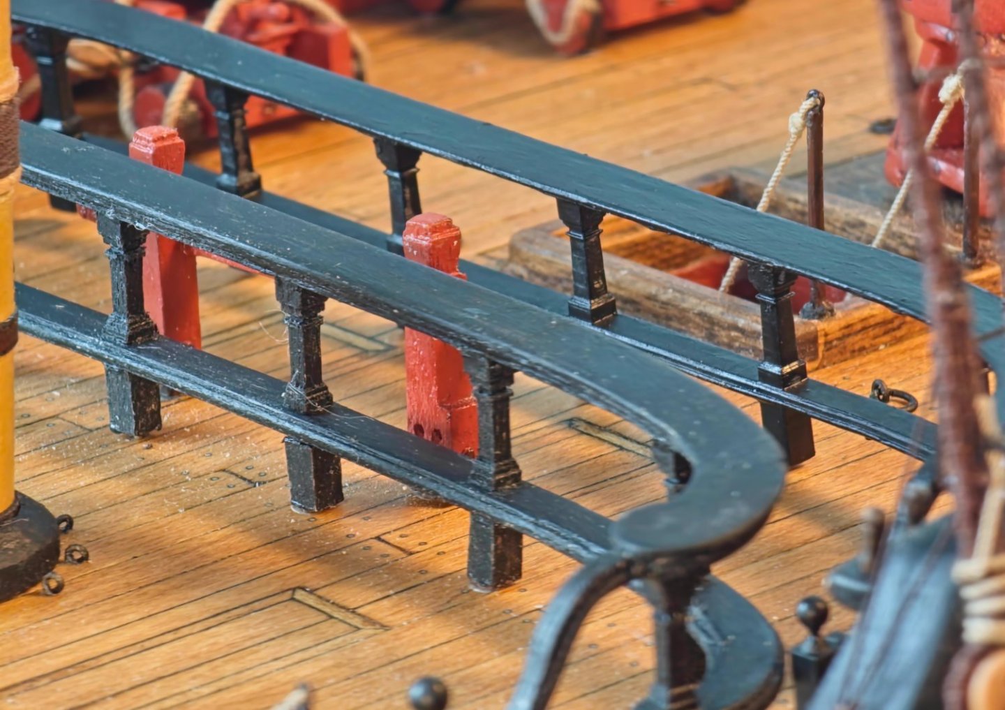
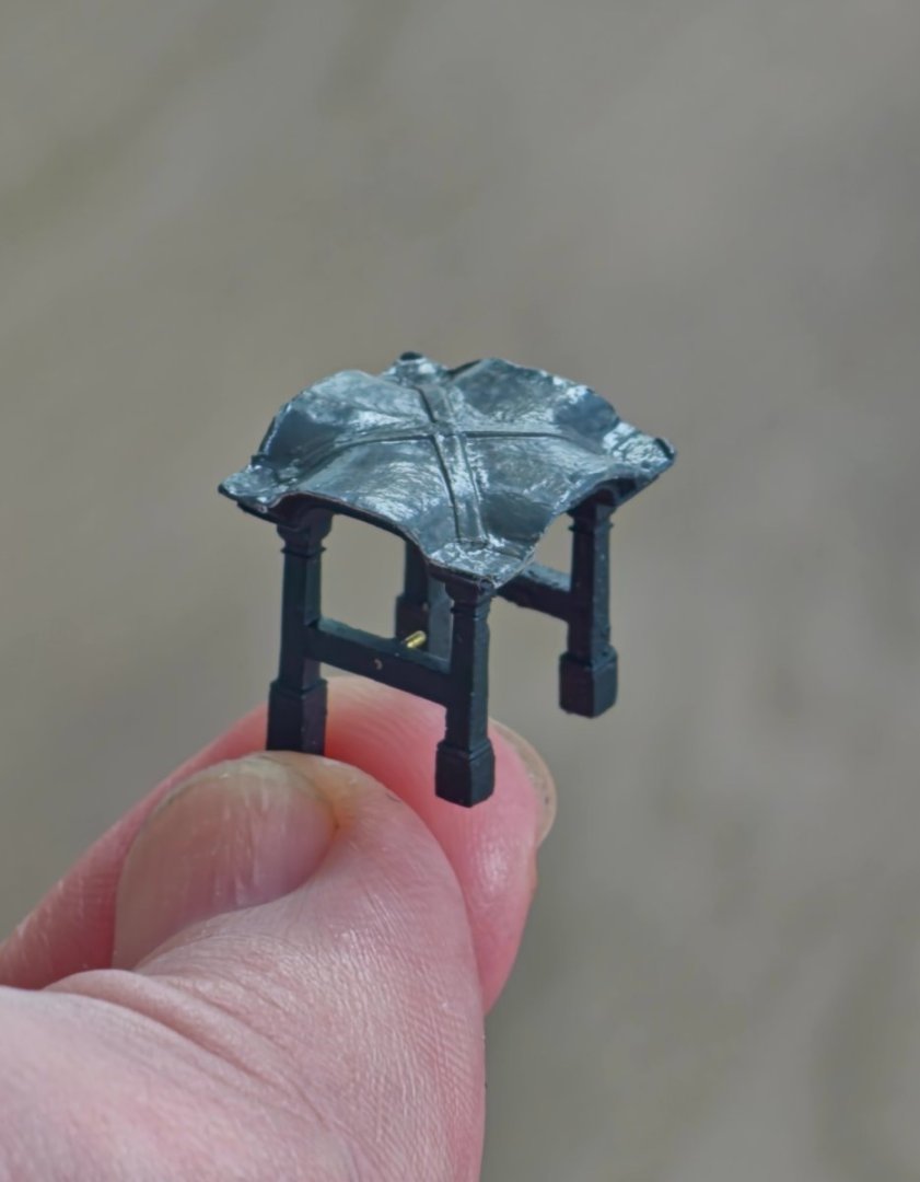
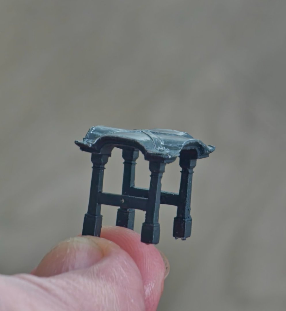
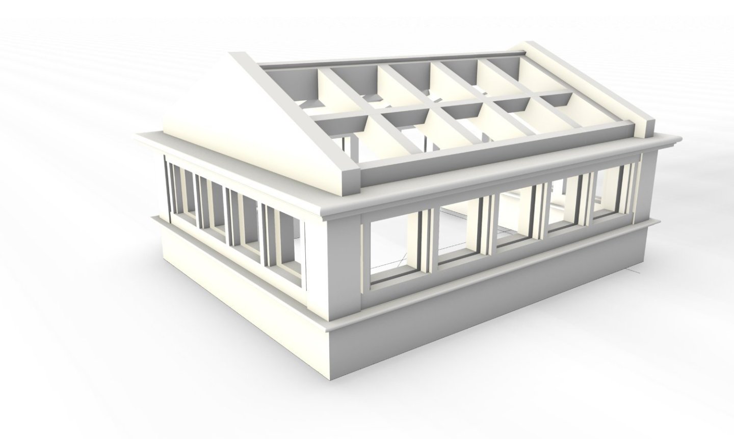
Still dithering about with the Jolly Boat. I eventually bit the bullet and splashed out on a new resin 3D printer. I got the Elegoo Saturn 3 Ultra 12k and the Anycubic Wash and Cure. Not a great amount of research went into this as it was the only one that was available in the store at the time. I think that it is a fairly good machine though and should be more than good enough for my needs. I am now feeling like one of those old dogs that is forced to learn some new tricks as I try to work out how to produce an acceptable print. You know you are in for a whole lot of pain when all the articles you read start off with the phrase that resin printing is more art than science. The first foray into the resin world was not a great success. I thought that I should have a stab at the Jolly Boat as it was this that caused me to buy the set-up in the first place. I thought I should take some advantage of the new capabilities and try to print the entire set of futtocks and keel at the same time thereby saving myself a few assembly steps. I had to revisit the CAD model and put it together virtually so that it was a complete structure rather than an assemblage of parts. I also took this opportunity to thin the futtocks down from the chunkier versions that were necessitated by my previous printer. I modified the detail around the sacrificial tabs so that I could snugly fit the wash strake from the get go and hopefully prevent the futtock non adherence issue I encountered in my previous prototype. The finished model was exported and imported into the new slicer program. I then had to try and orient the model to ensure a successful print and achieve the optimum print quality and support location. I suspect that this stage along with the myriad of settings is where the art lies. Once all that was out of the way I transferred the file over to the printer, loaded resin, pressed start, and went out for a beer as this is not like a paper printer where the result shoots out in seconds. Several hours later I went back and it looked like a mess of spaghetti but I could discern a model amongst the support structure. Then it was over to the wash station and after that was finished it got a quick blow dry using the airbrush and I then had it rotating in the cure station like a midnight kebab. After removing the supports and giving it a cleanup, it was ready for comparison with the previous version. The resin print is a lot sharper and the ability to produce results on a much finer scale is commendable. I wish I had access to this a couple of years ago. I would have improved the resolution of a lot of the details where I had to compromise due to the limitations I was labouring under. Unfortunately, the futtocks are so delicate and, while the material has some flex, it is very brittle. I snapped off a whole lot while trying to free the frame from the support structure. I have subsequently found out that I would have had a better chance if I had removed these supports before curing but I need an alternative method as the futtocks are too small to be glued back on and just one failure would set me back. I also noticed the keel does not possess the required stiffness a keel should possess which may result in some unwanted distortion. I replaced the lower section with some walnut which solved that issue. I did some googling and found out that there are other resins available that have different structural properties. I have sourced one that is for engineering purposes and seems to have better performance specifications although I think that the cross-sectional area of the futtocks is too small to be completely resistant to sudden fracture but it should give me a fighting chance until the planks are in place. Before heading out to the shop for new resin I thought that I might try and hone my skills by printing out various other bits and pieces of deck furniture that I have already constructed namely the barricade, belfry, and skylight. This will give me an idea of what is and is not possible and how much detail I can include before it becomes invisible at the scale I am working with. As these are structures that I have already completed I will have something available for comparative purposes. I had a go at drawing these up and then running them through the printer. The speed of the print is determined by the vertical travel distance so I can cram in a whole lot into the horizontal footprint of the print bed without affecting the print time. The pre-print drawing does look like a tornado travelling through an antique shop though. The first element that I attempted was the quarterdeck barricade. I had already built a CAD model of this but I needed to do some work on this to make it printable. It came out OK with fine a lot of fine detail preserved. I am not sure if I will swap this out as I have grown fond of the crude homemade workmanship of the original. Another piece that seemed to be suited to the printing technique was the belfry. This led to more CAD work based on a combination of the drawings in the AOTSD, details from the NMM plans, photographs of the HMS Victory belfry and my own interpretation. I could have printed this all out in one model but I decided to split out the bell beam and the bell so that I could introduce a more natural joint. I drew up two versions of the Bell. One as per the AOTSD and the other with more exaggerated articulation as I did not think that the original detailing would show up at the 1:64 scale which turned out to be true. I should have also increased the wall thickness of the bell as the printed version was so thin to cause it to collapse under its own weight. The first print of the belfry was not bad in terms of the detail included but the roof looked a bit flat so I exaggerated the proportions slightly for the second go around. I had used copper sheathing on the roof of my original timber attempt but I was never happy with the scale of the patina that I ended up with. For this version I decided to go with a lead sheathing. While the current HMS Victory belfry appears to have copper, I suspect that they would not have been that extravagant back in the day and lead would have been the go-to material. Not having access to suitably thin lead I tried to mimic it using stainless steel sheet but that was hard work so I resorted to plain photocopy paper that I painted grey to try and look like lead. I cannot show a photo of the bell in place as I shattered the bell beam trying to force the brass supporting rods into holes that were slightly too small. The material does not have the forgiving flex of styrene. The other piece that I was never happy with was the skylight on the quarterdeck. My first effort was quite clumsy as I could not get the members fine enough. I have not been able to find any detailed drawings of an 18th century skylight so I had to rely on descriptions in Lavery as well as what can be seen on HMS Victory and HMS Trincomalee. I used a lot of artistic licence and treated it as a bit of a test bed by introducing some articulation. This was to make it look more like a joinery item and to see how small I could go before the details become invisible to the naked eye. The first prints did not work as the gap that I had left for the glazing closed up during the printing and the mullions were too thin to maintain structural integrity. I redrew this using thicker sections and a new method for incorporating the glazing by printing the entire frame assembly in two separate pieces with the glass sandwiched in between. The new chunkier sections are not a million miles from the sizes I used in the existing model. The 3D printed version has a lot more detail than the original and has a bigger glazed area so that it might be possible to get merest of glimpses to the deck below so I may go ahead and swap this out. There are visible details at 0.2mm which is finer than I can manage using traditional techniques. I seemed to have lost a lot more time while faffing about with my new toy so I should really get back to working on the model as it has been stalled these past few weeks.


-
Head Rails
DavidEN replied to DaveBaxt's topic in Building, Framing, Planking and plating a ships hull and deck
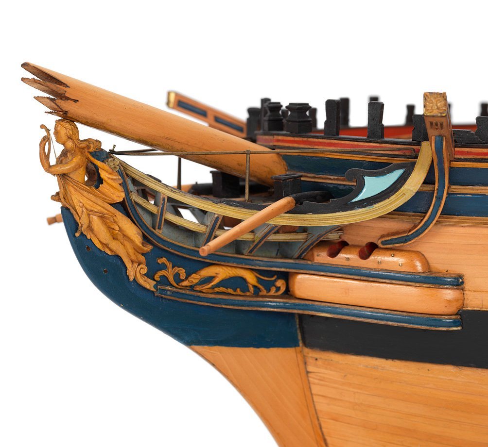
Hi Dave, It is present on two of the contemporary models of the Diana. I carved mine out of a block of timber but it was quite a tricky piece and it took a coupe of goes before I ended up with something that I could just about live with. Beef Wellington's is the one to aspire to. Regards, David
-
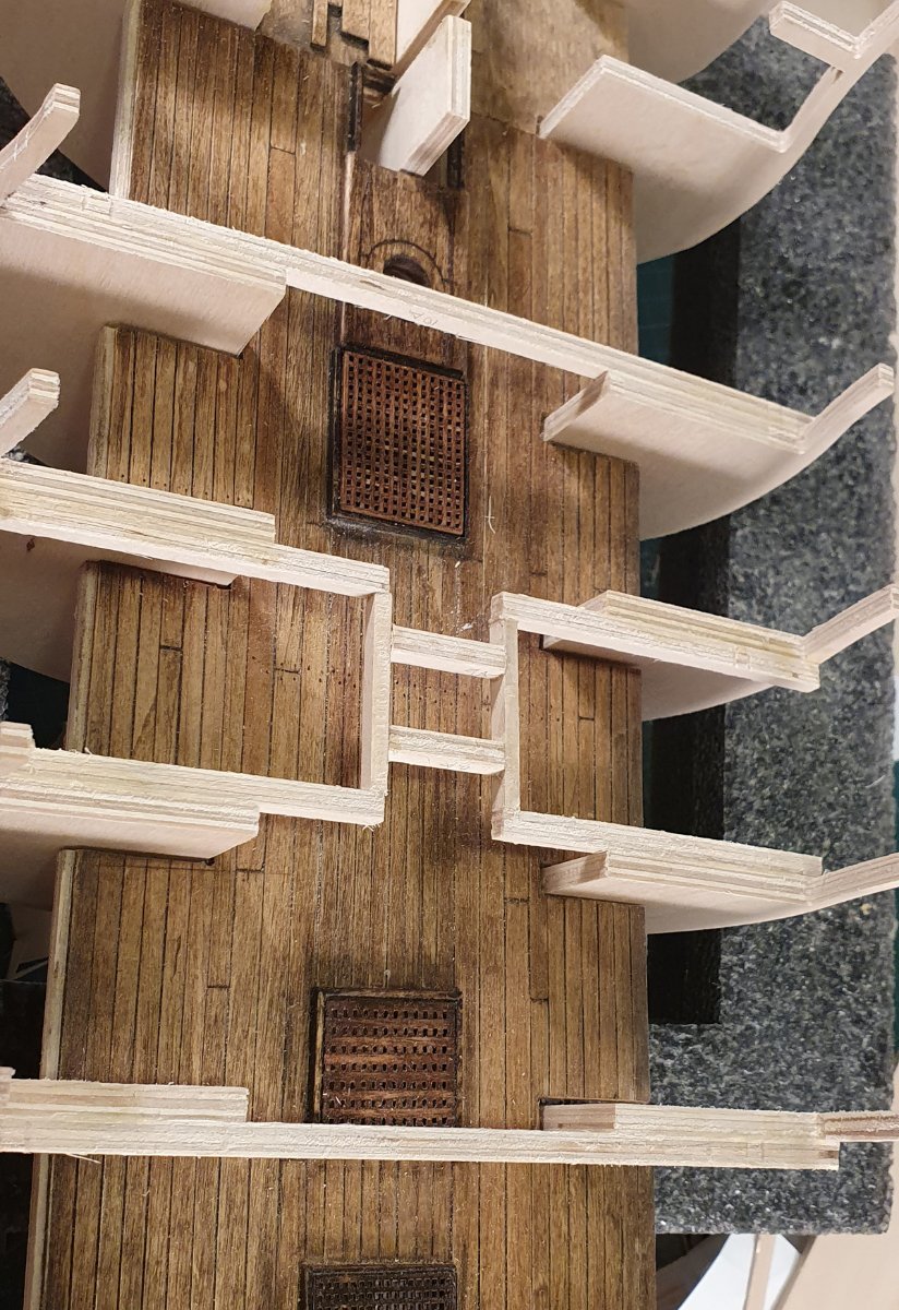
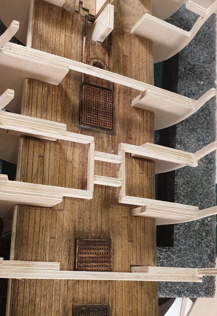
The beams are offset from the frames as they are glued to the sides of the bulkhead rather than on top as shown in the photo below. It is how they are meant to be installed as per the instructions so it should not be a problem. I did modify my beams though so that they did not run through the hatch openings but that would be hard to achieve in your case with the deck already installed. Regards, David
-
Thanks for the kind words Ross, B.E., Allan and Dave. I think that I have identified a few areas where I can make improvements so I am going to go for one more attempt. Of course I could just be kidding myself. Regards, David
-
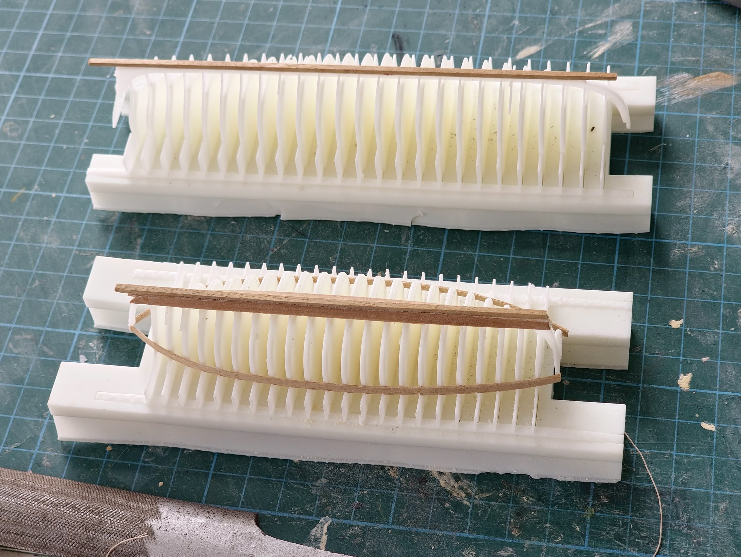
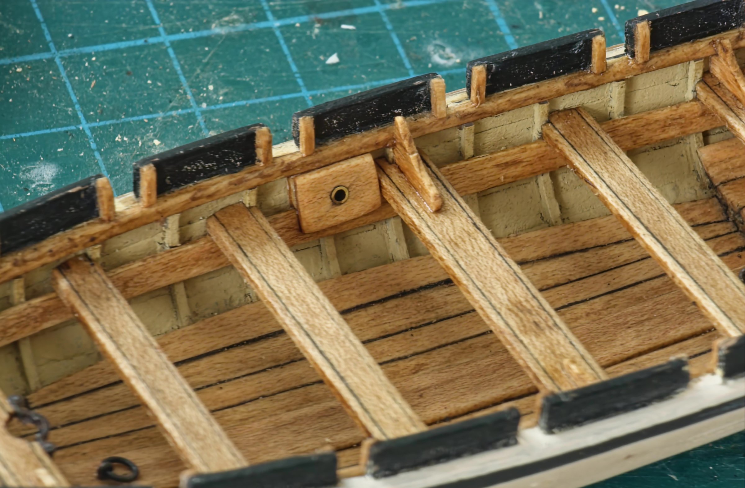
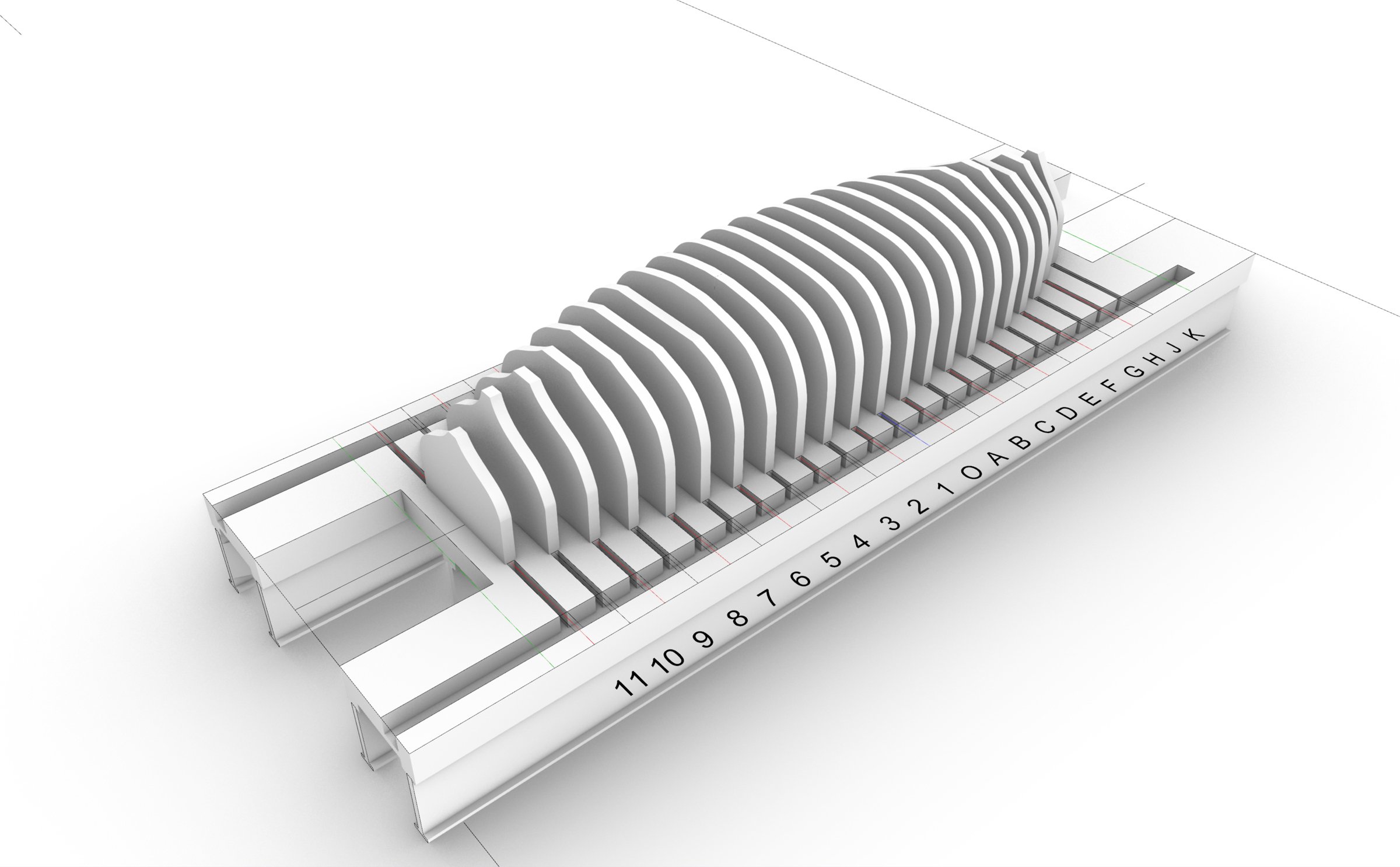
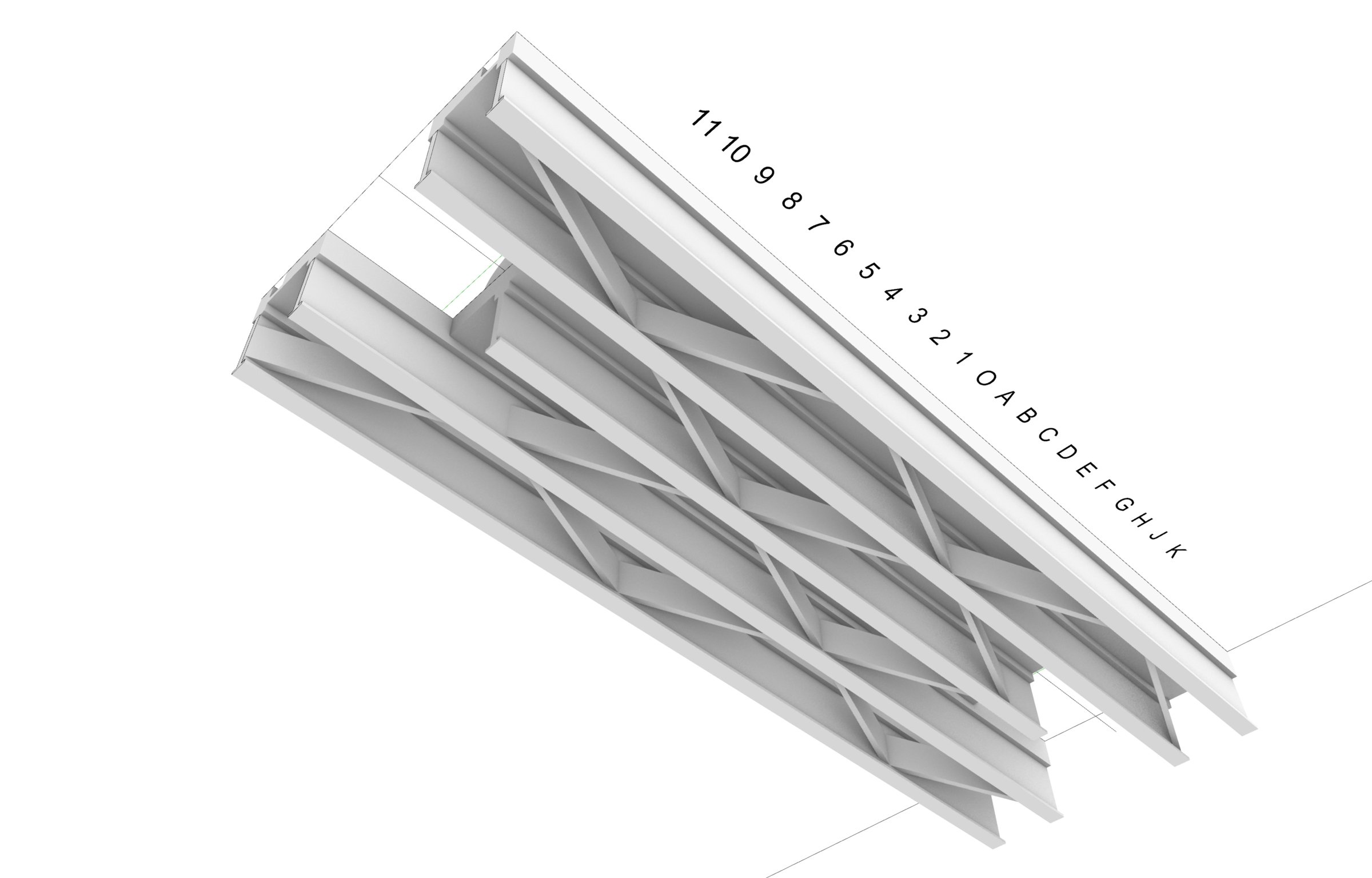
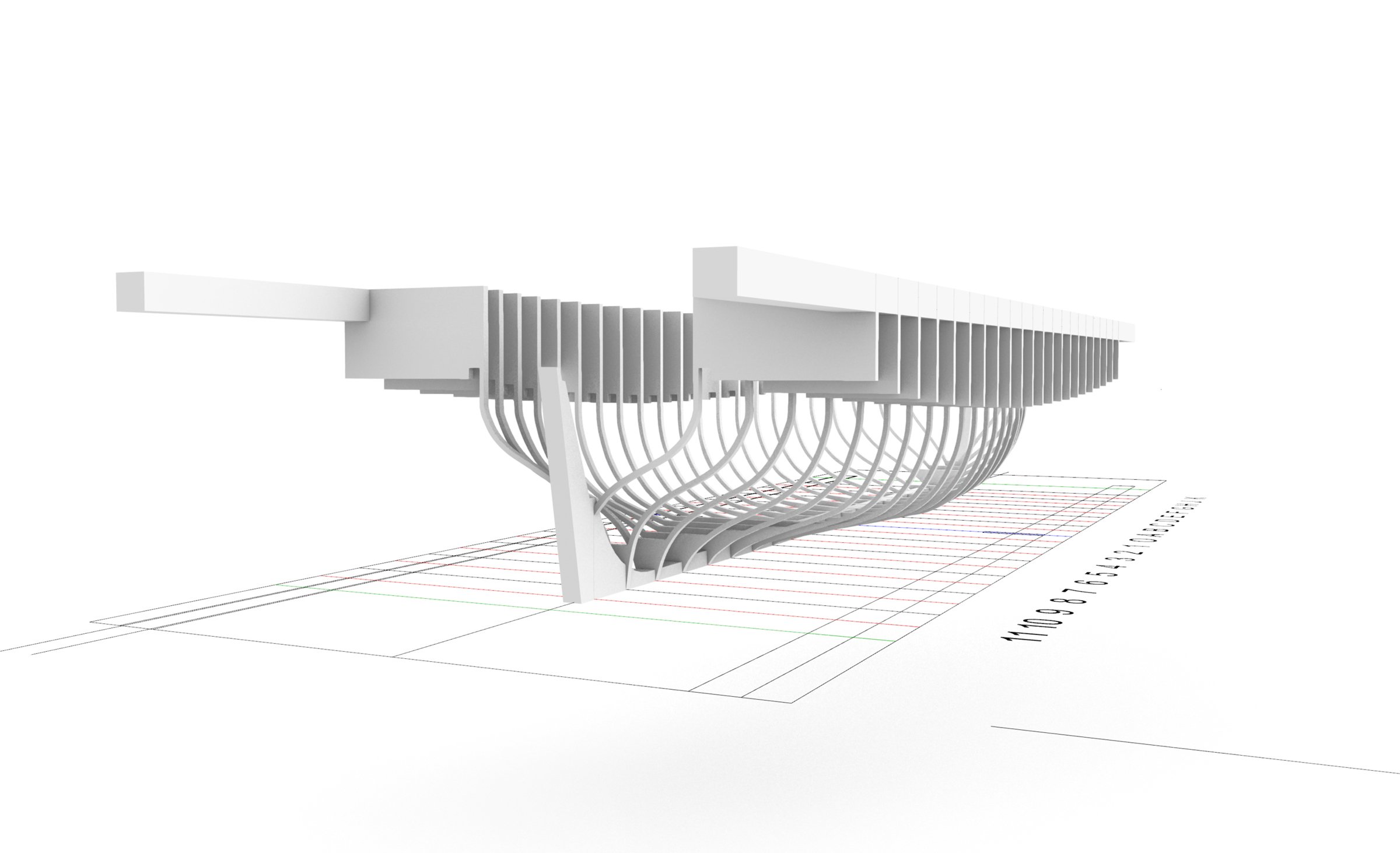
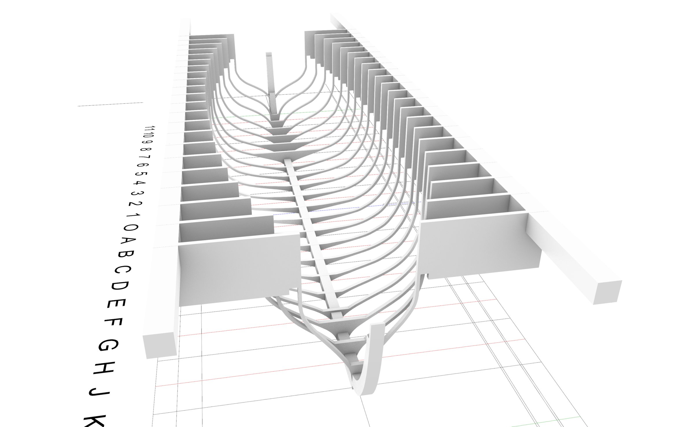
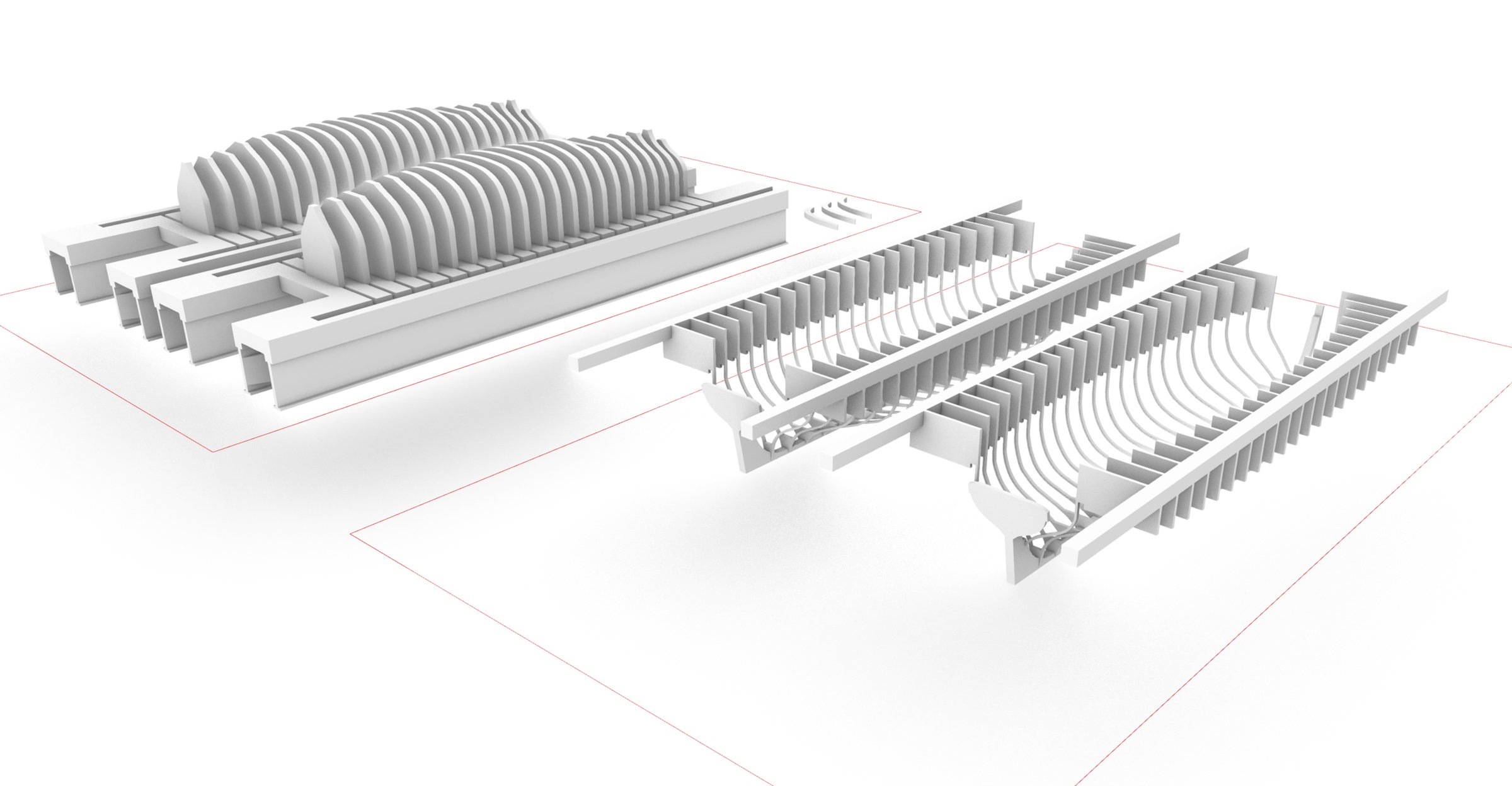
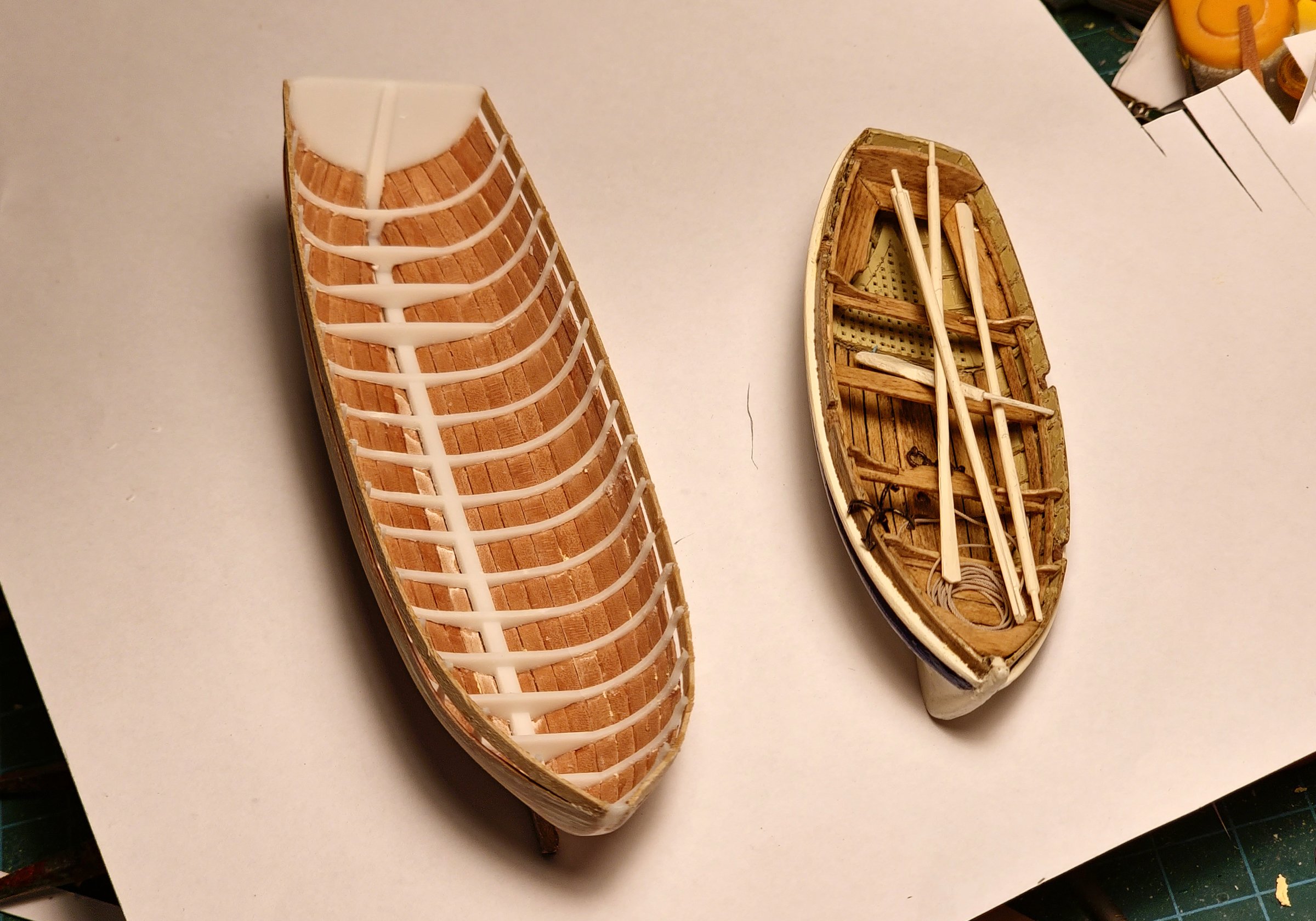
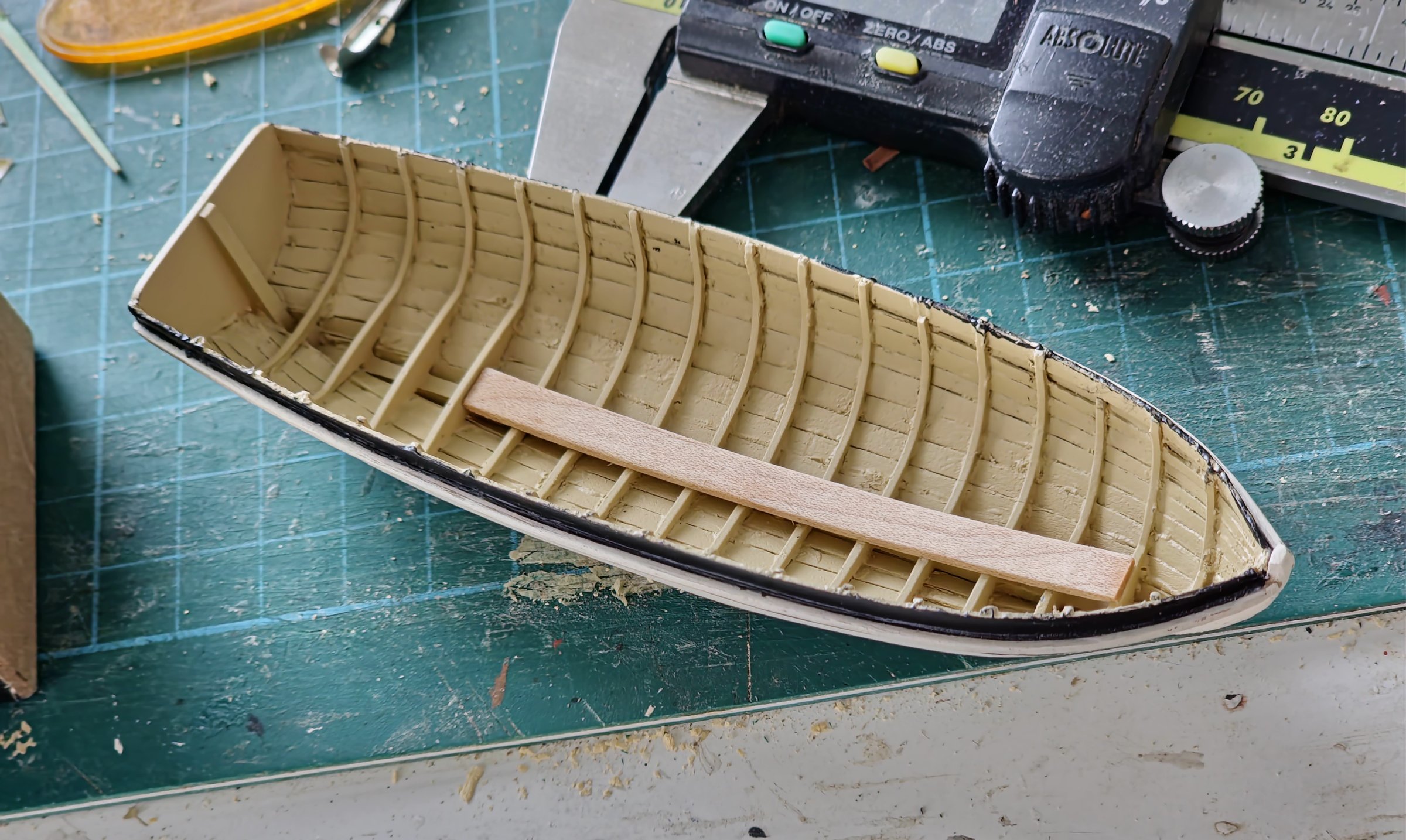
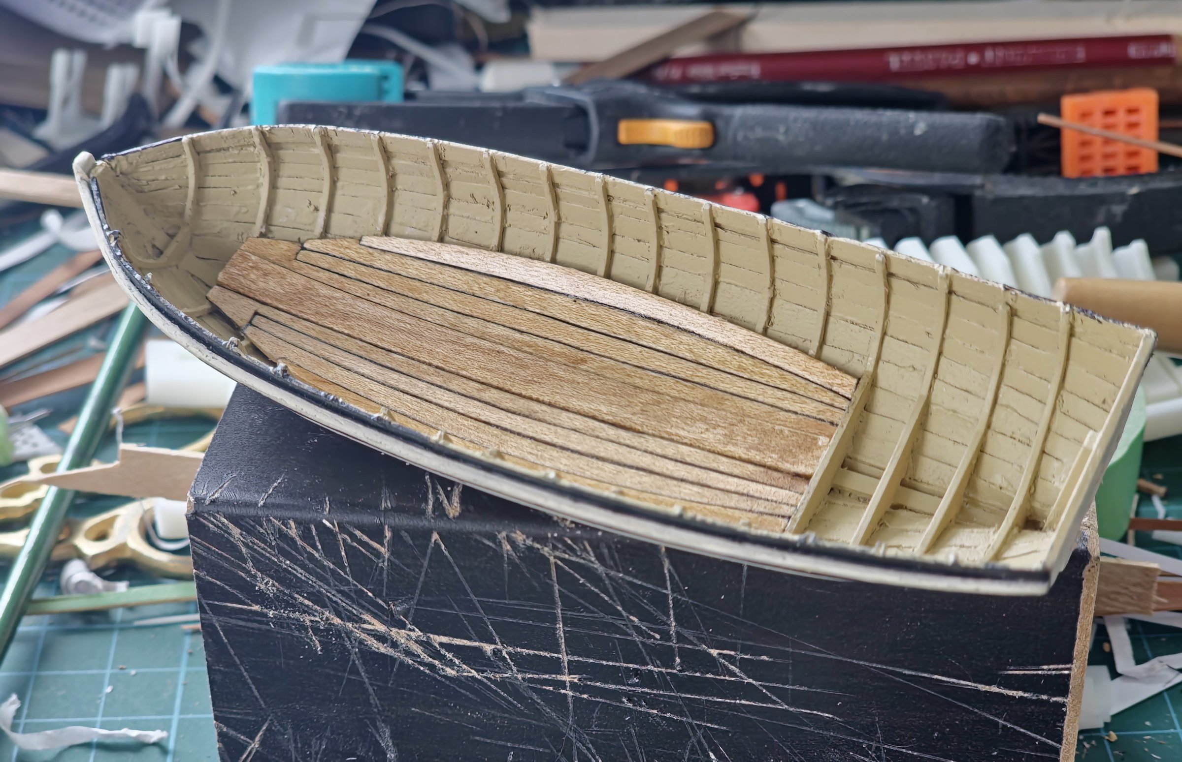
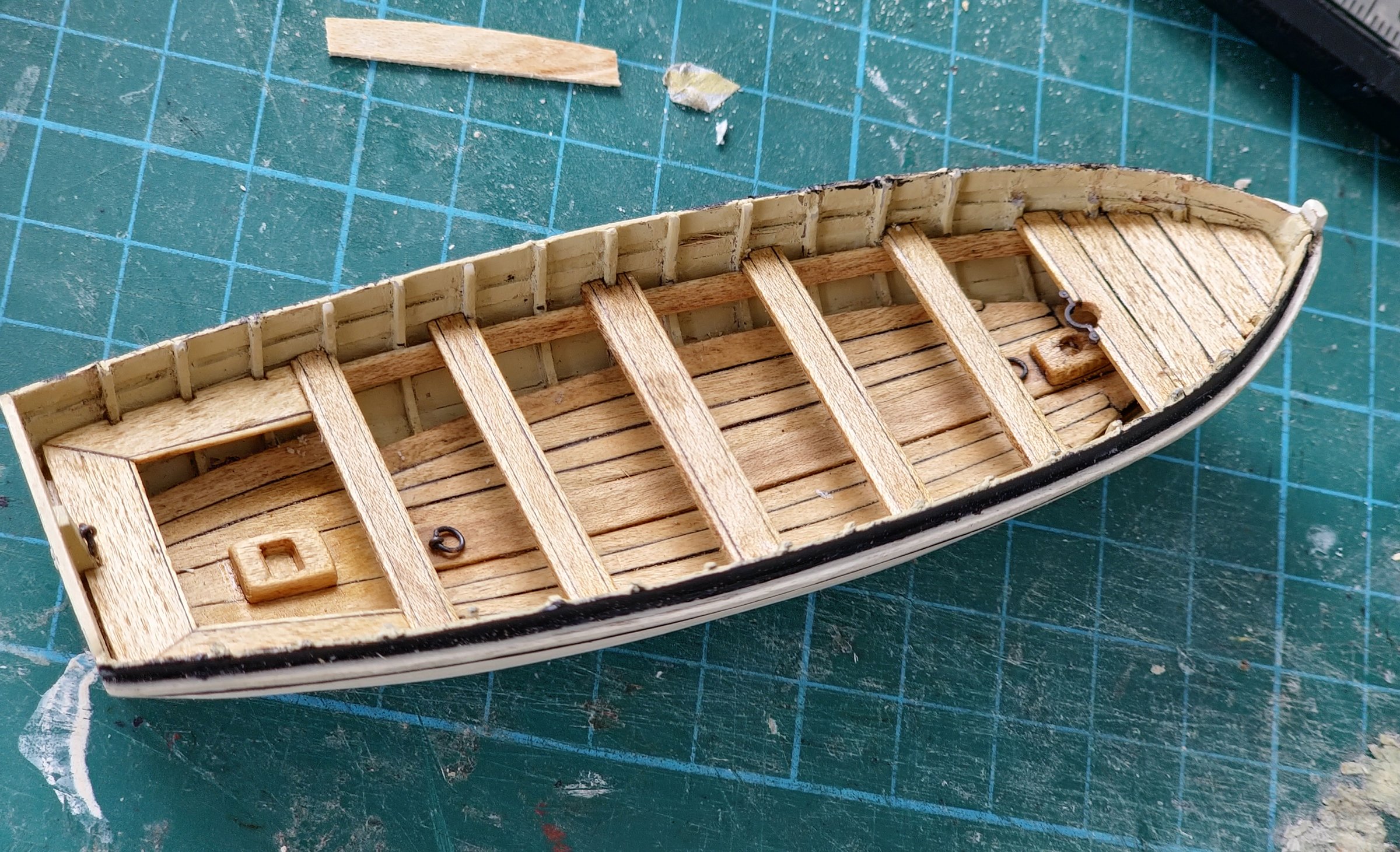
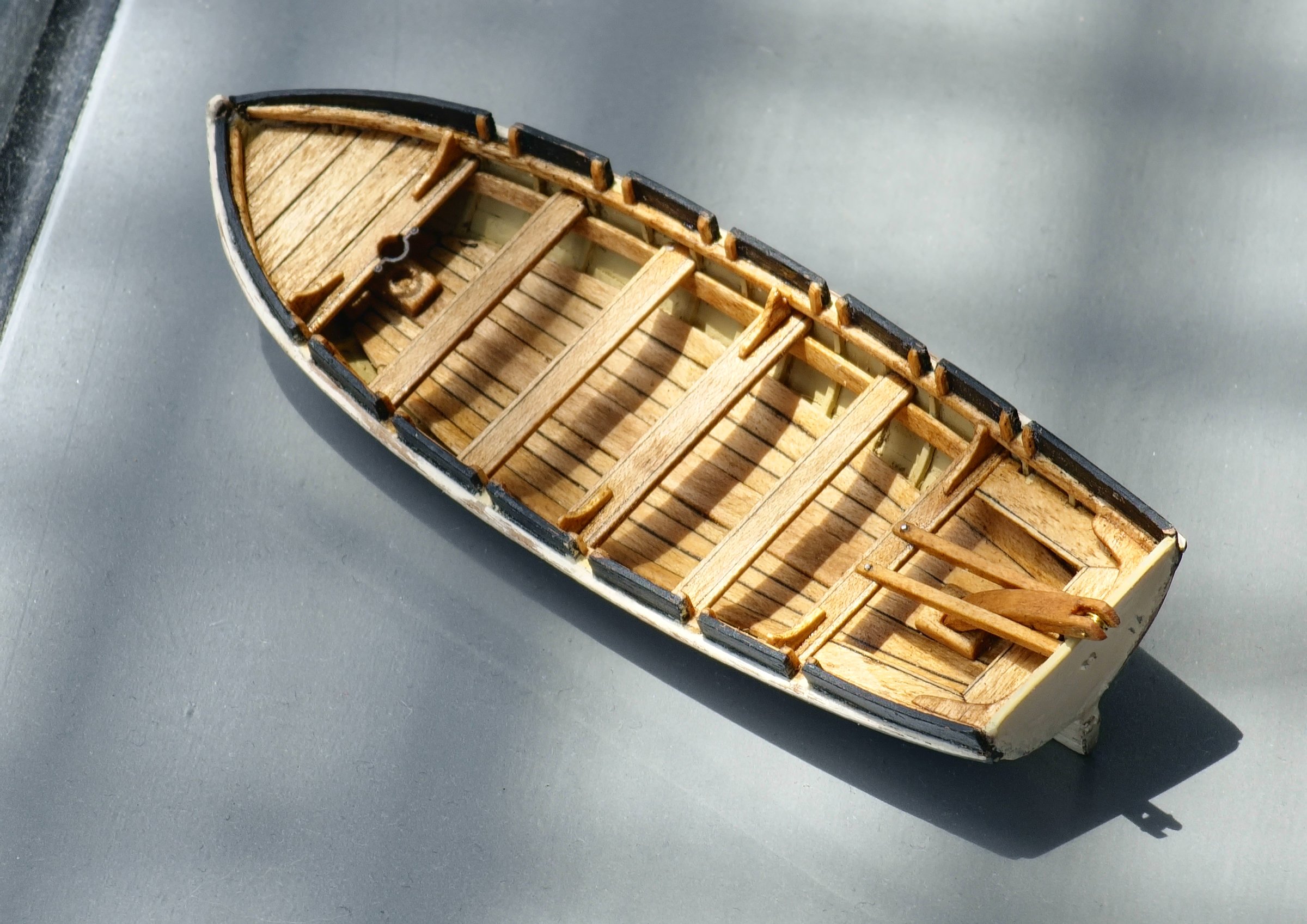
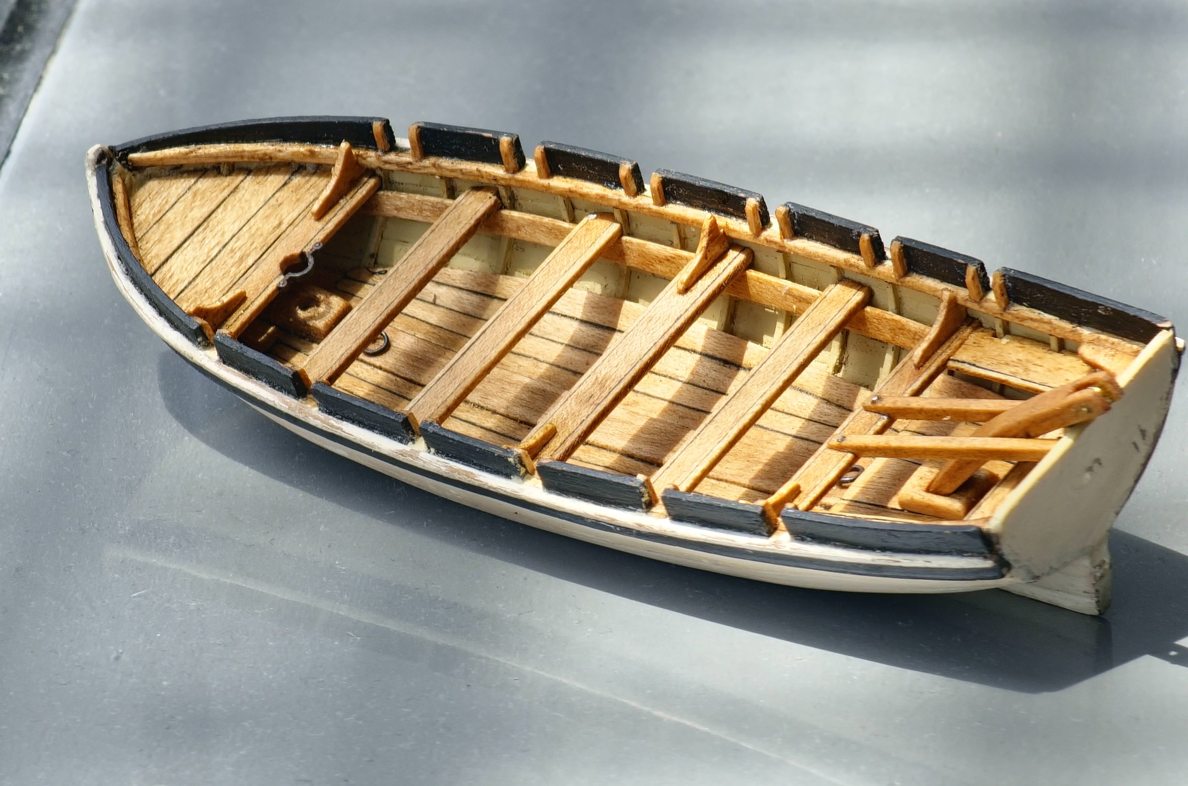
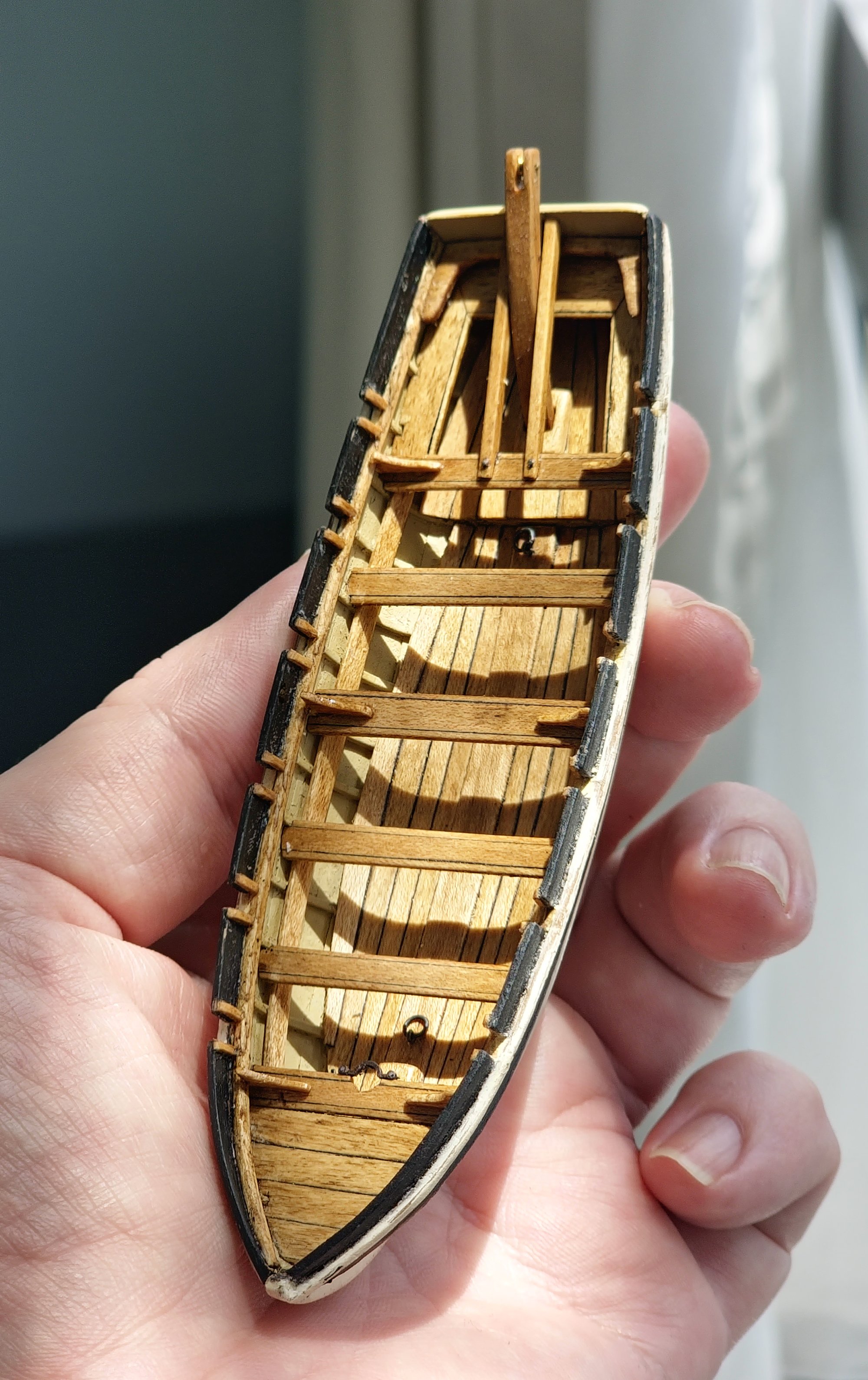
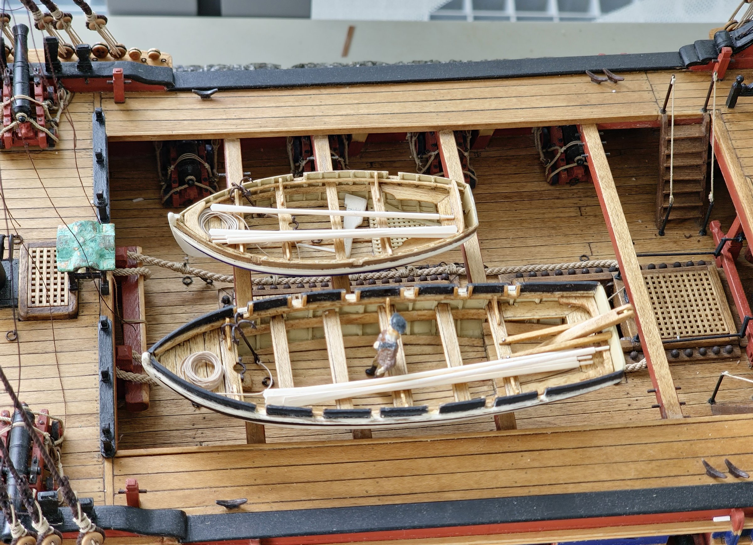
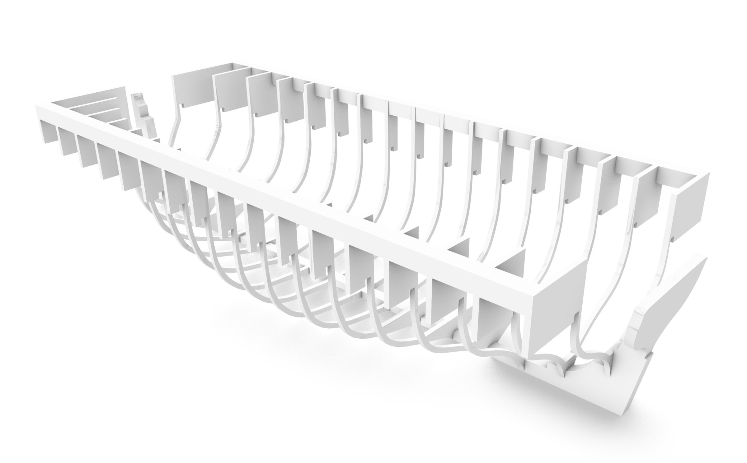
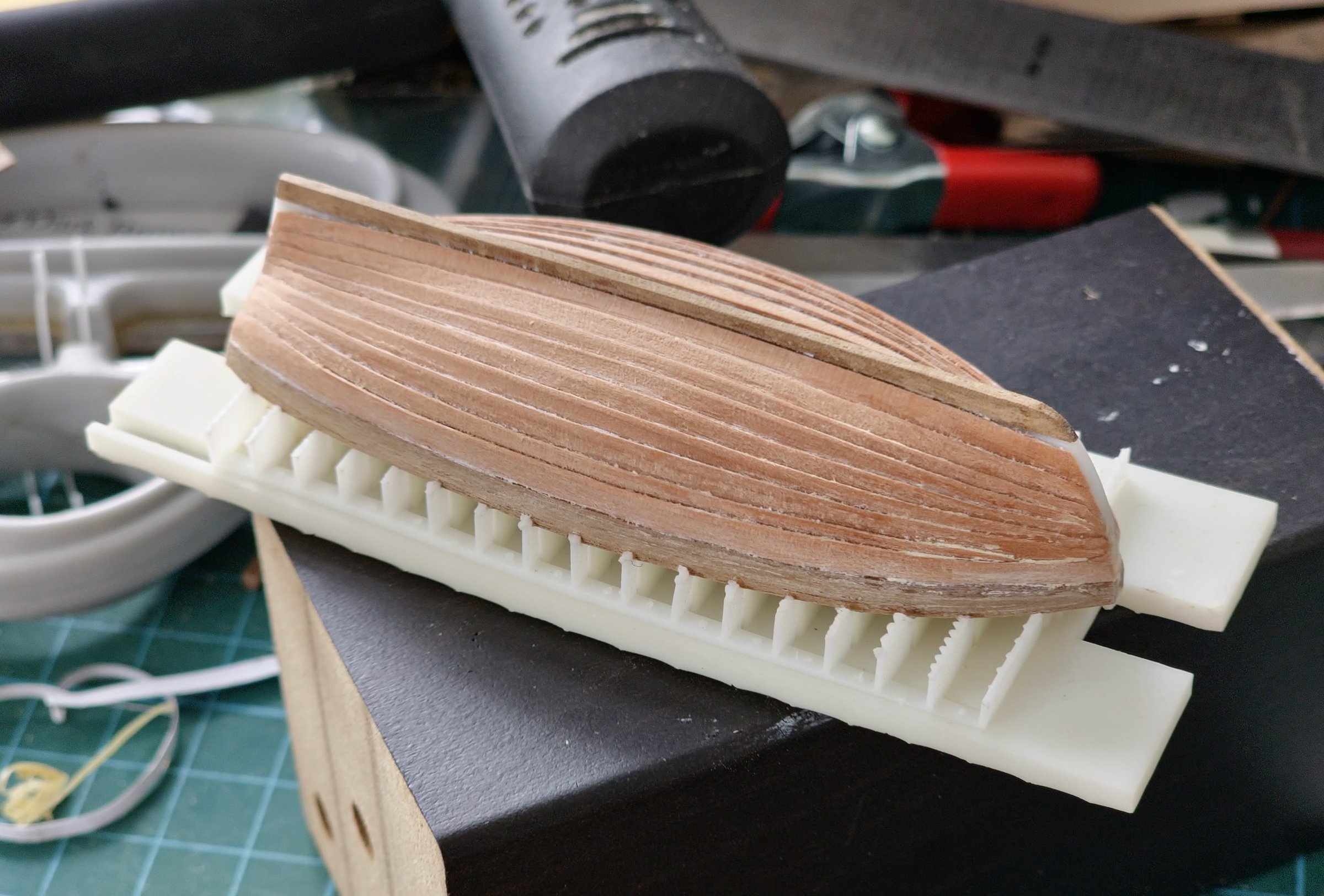
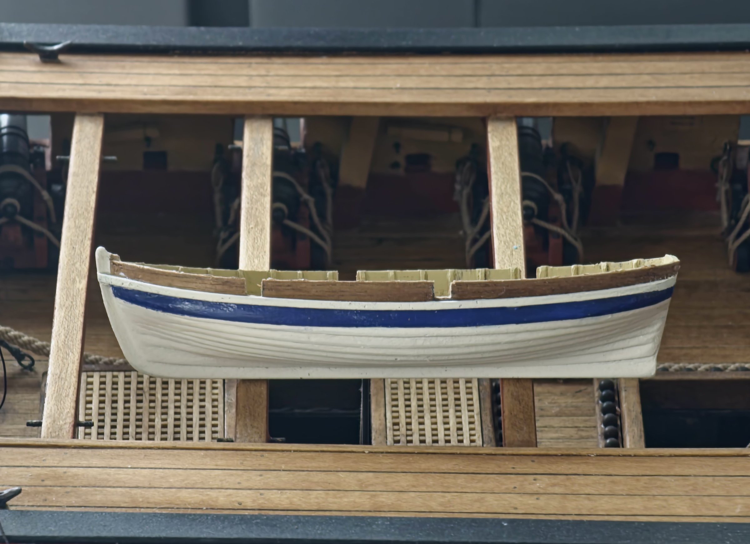
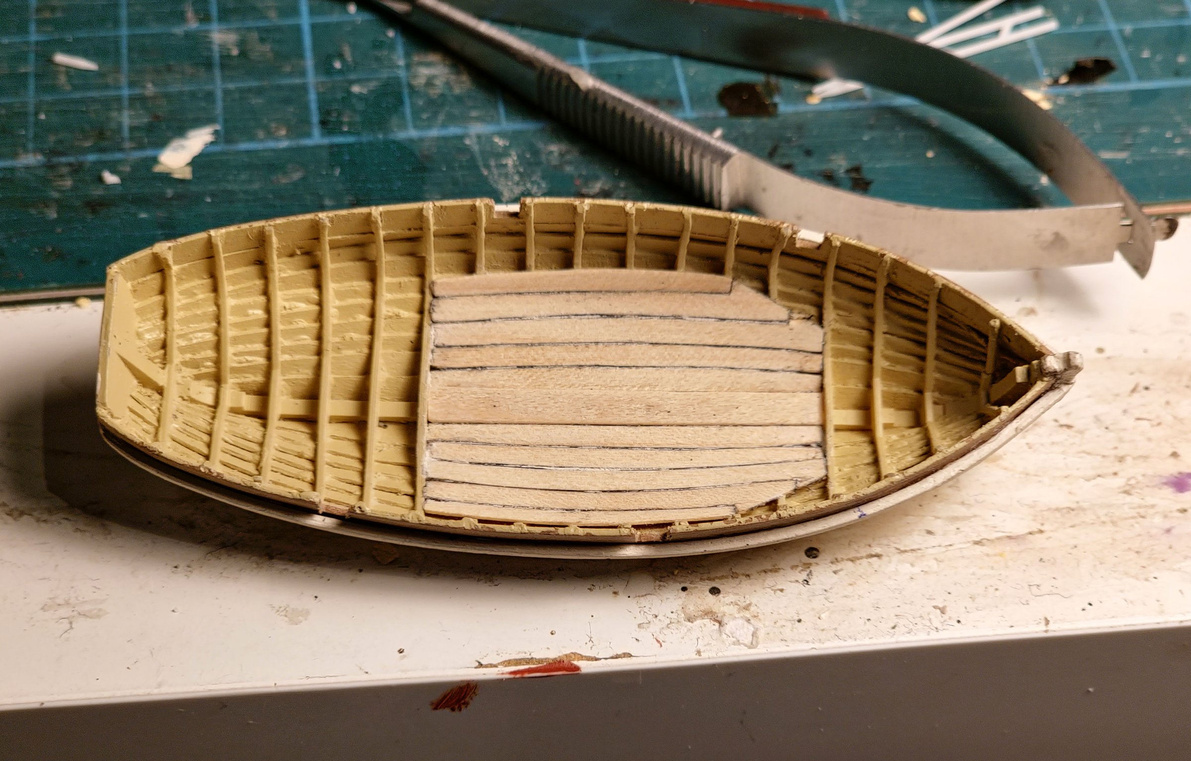
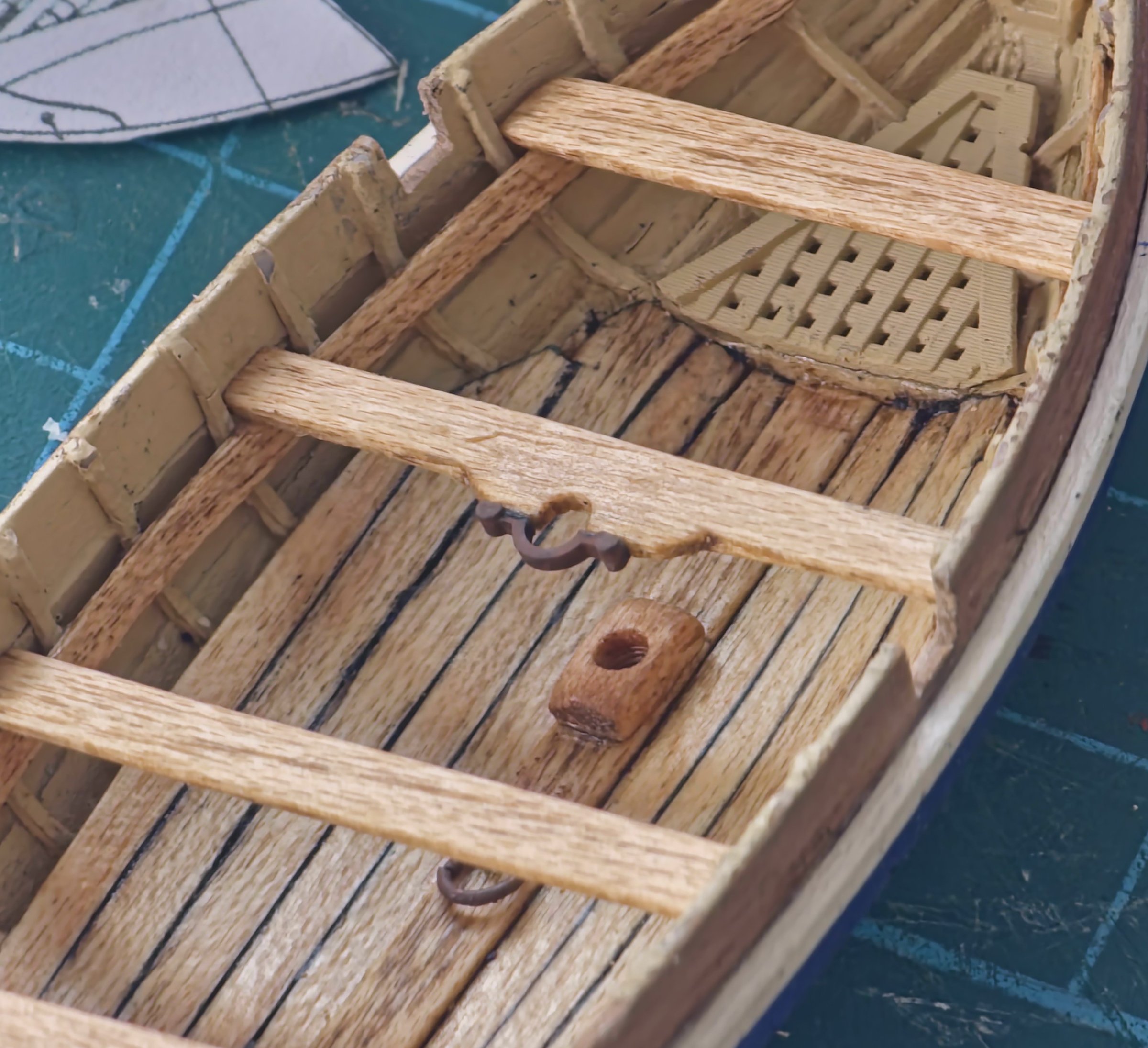
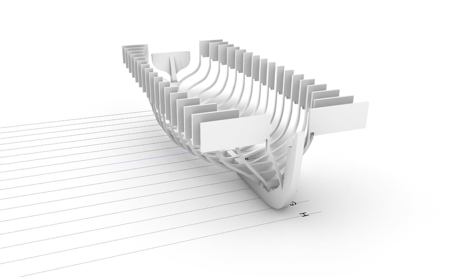
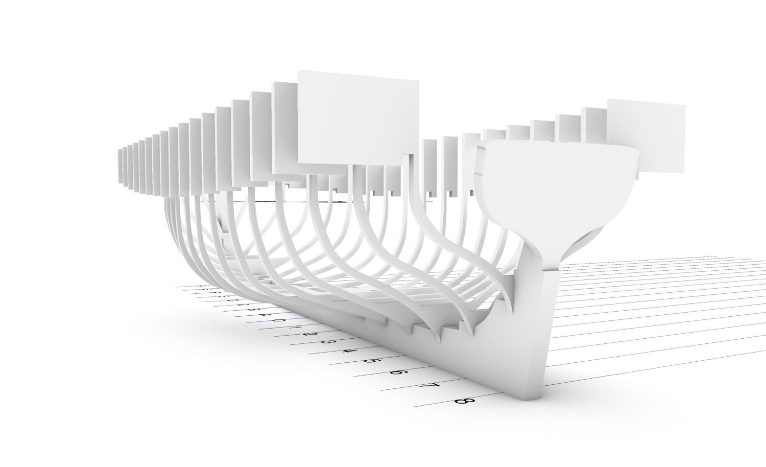
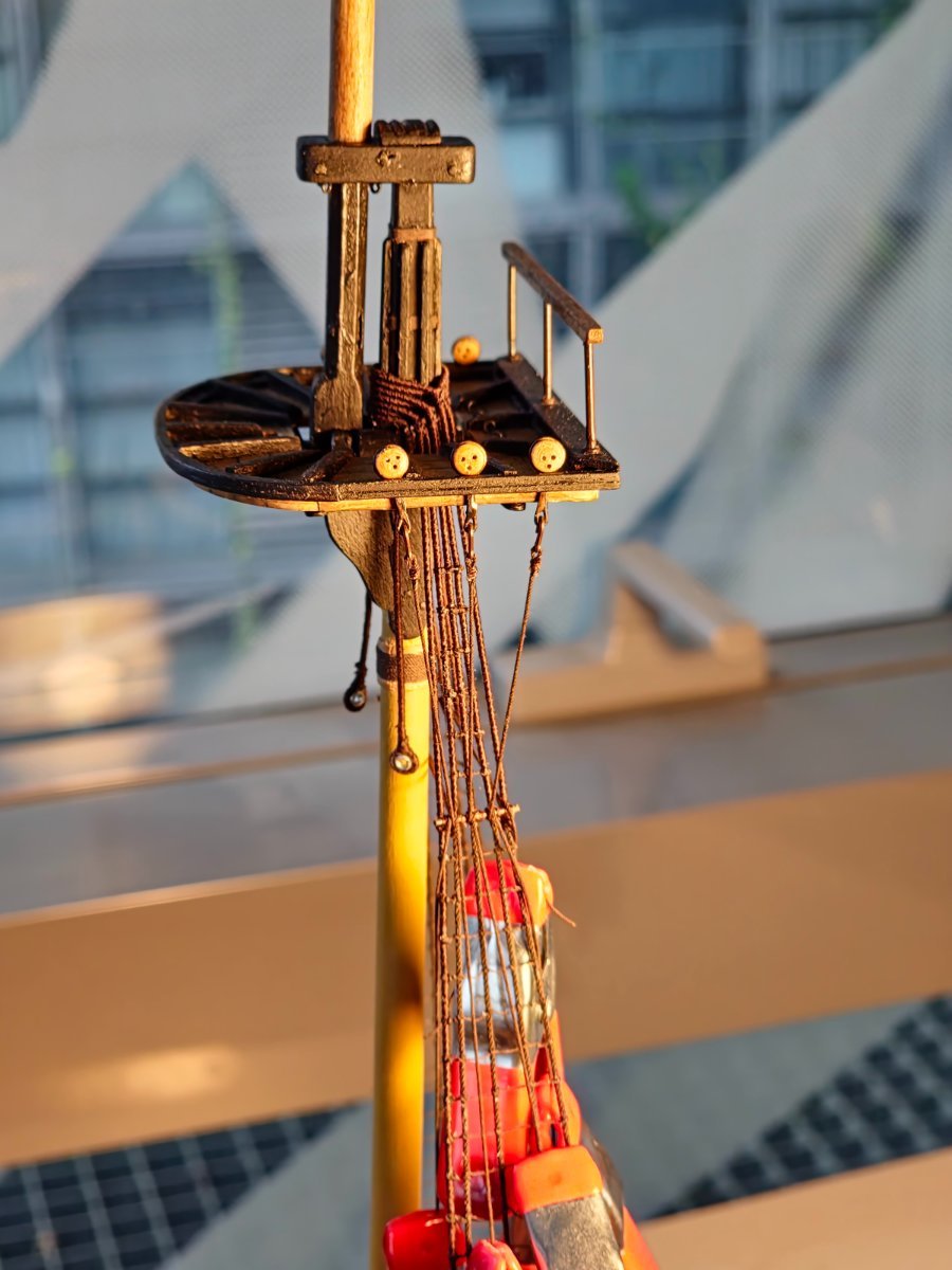
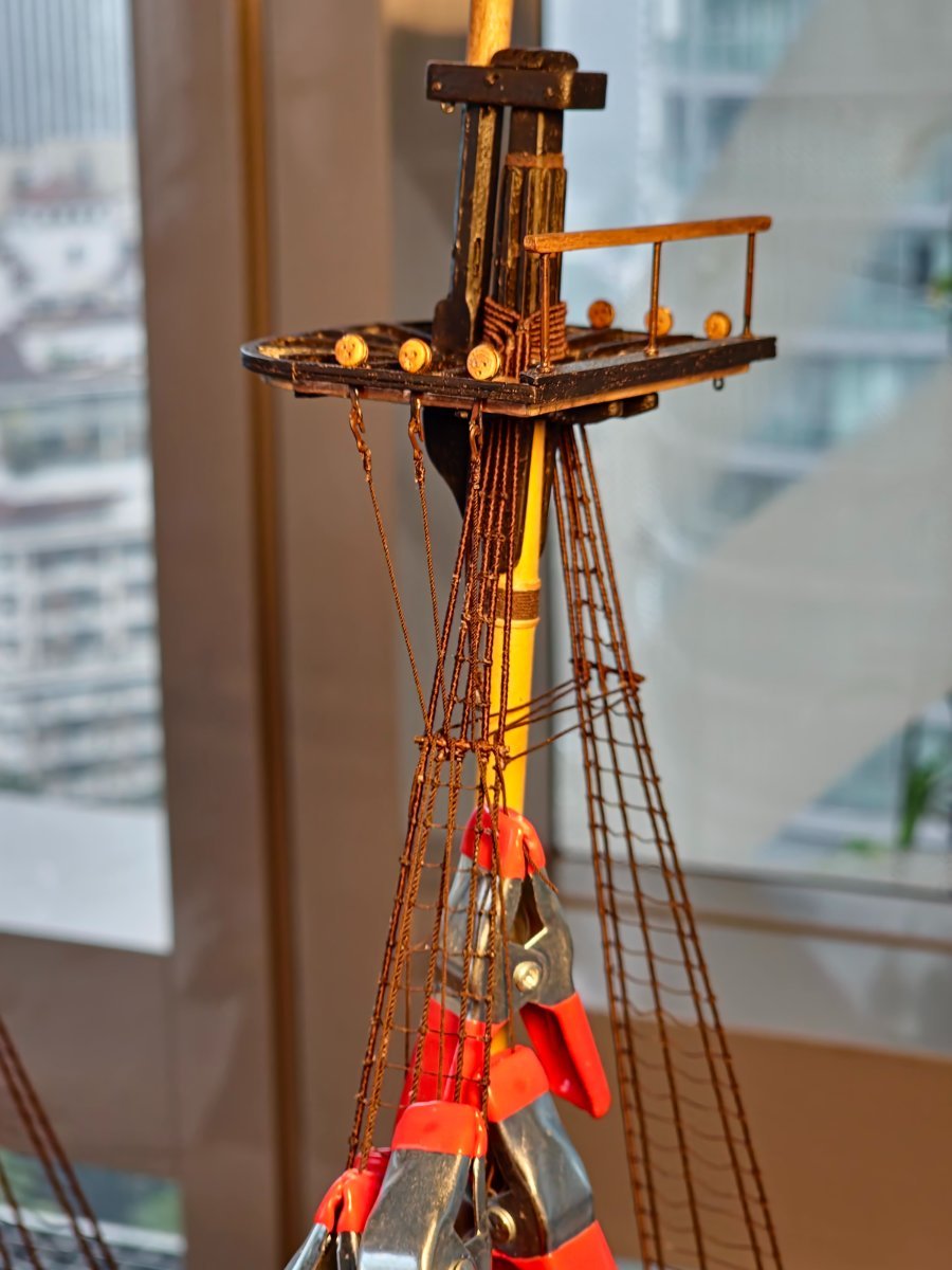
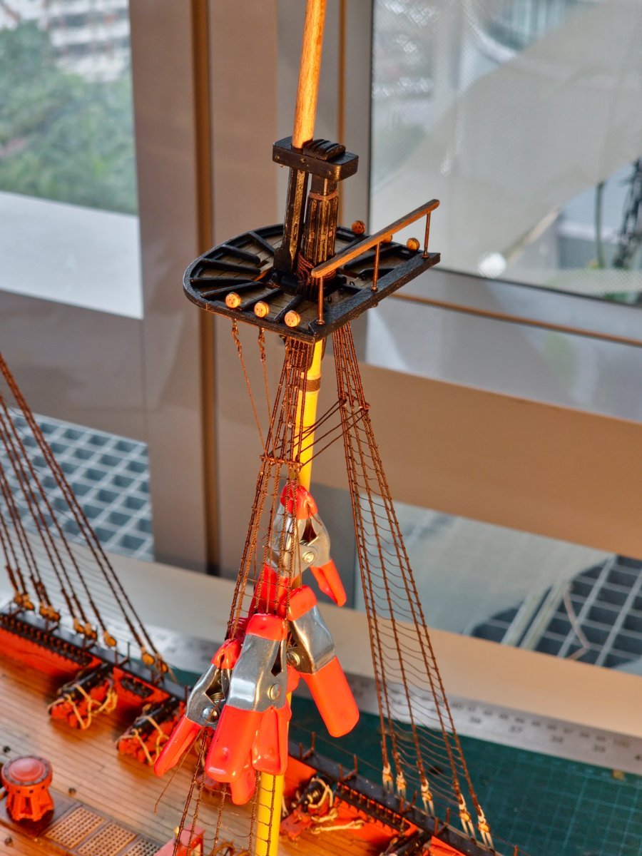
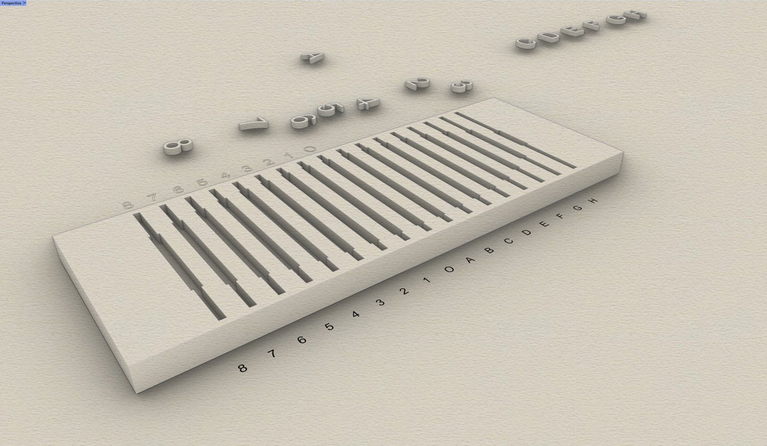
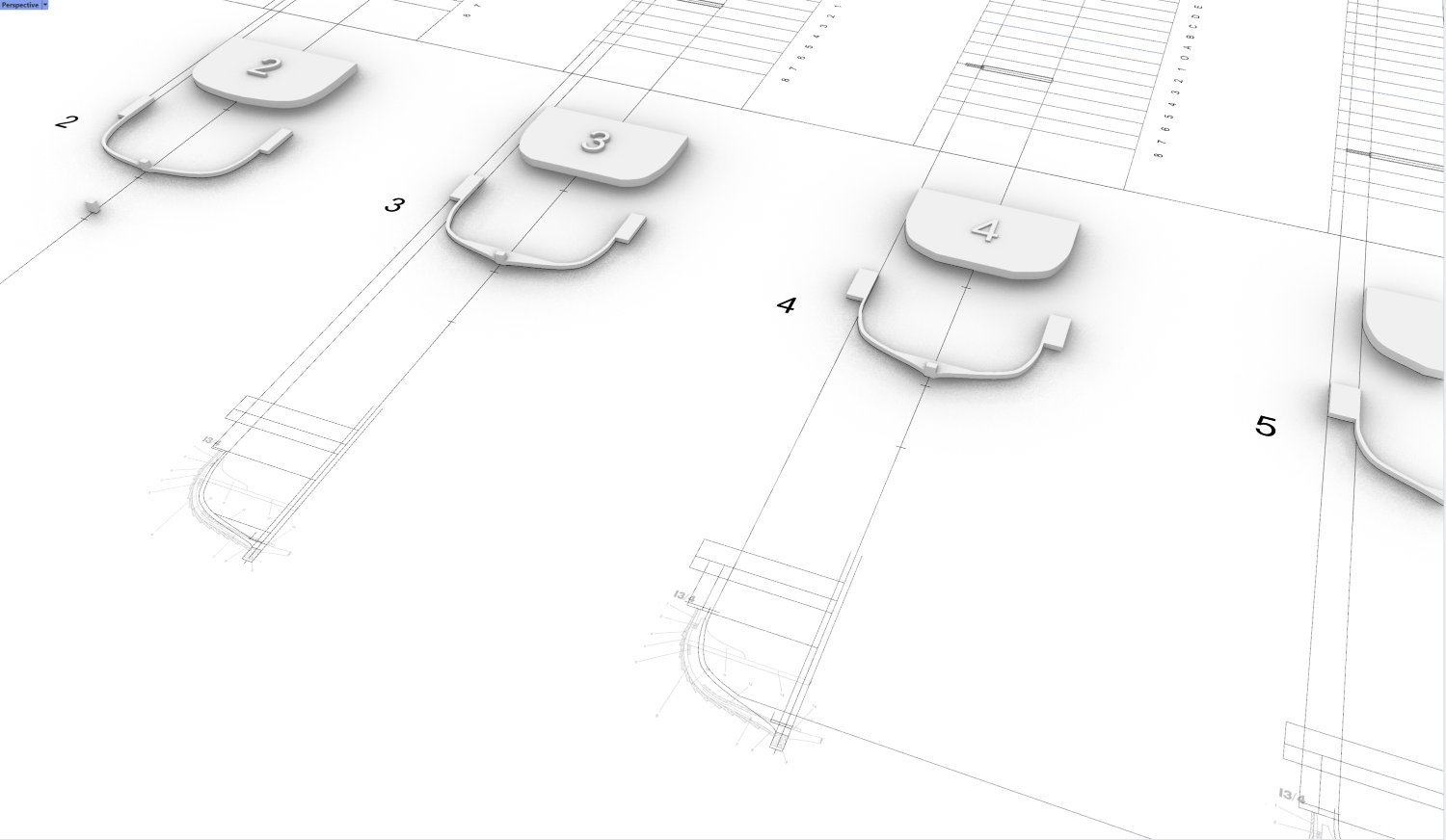
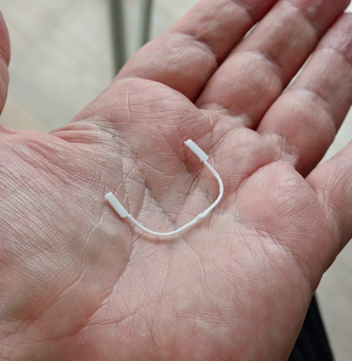
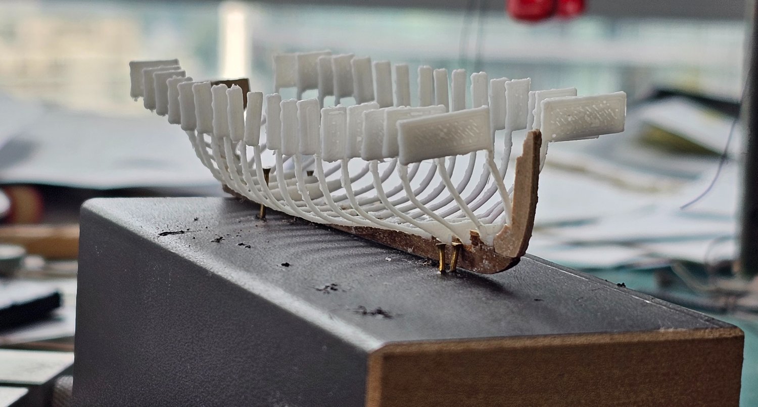
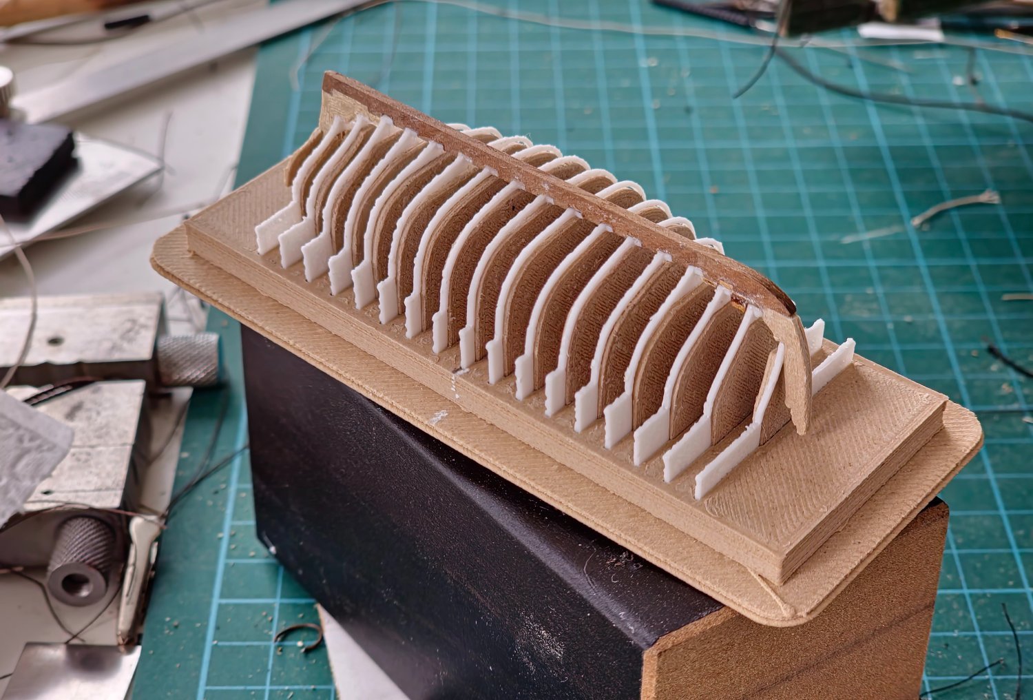
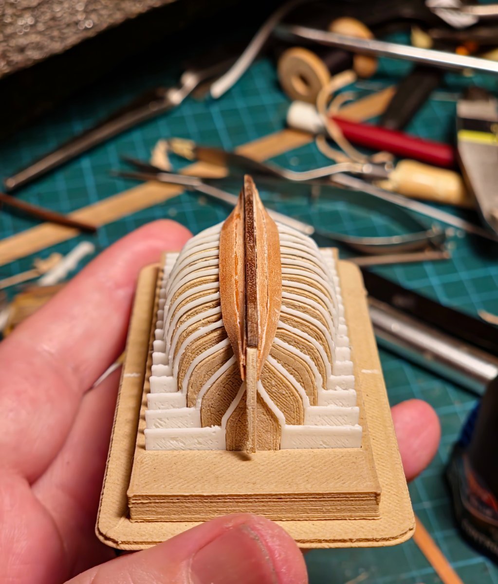
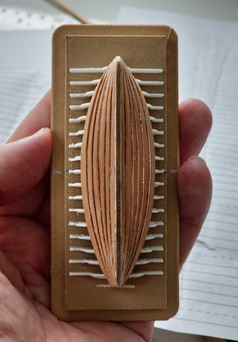
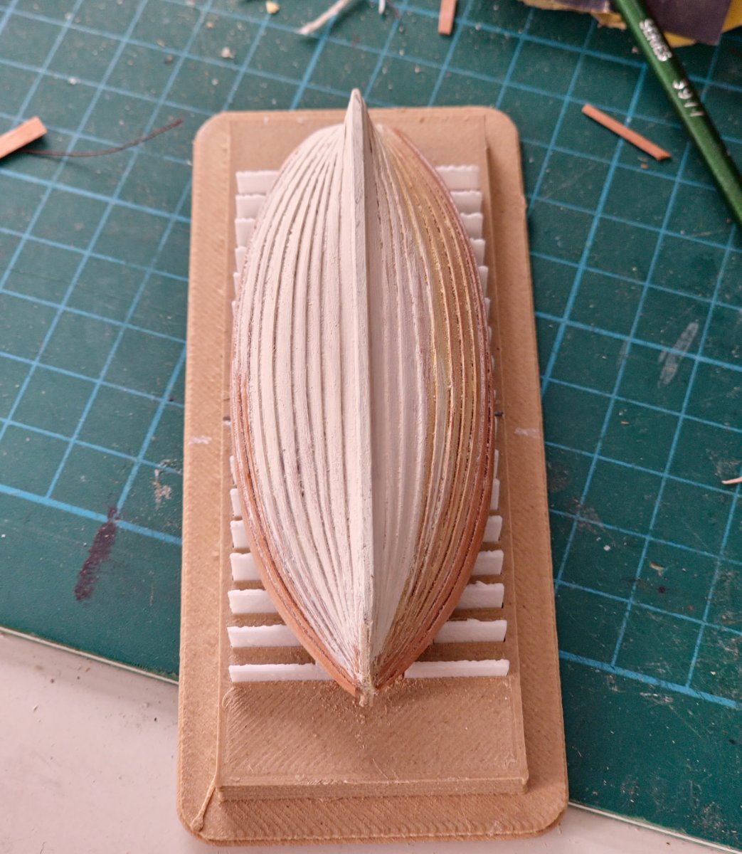
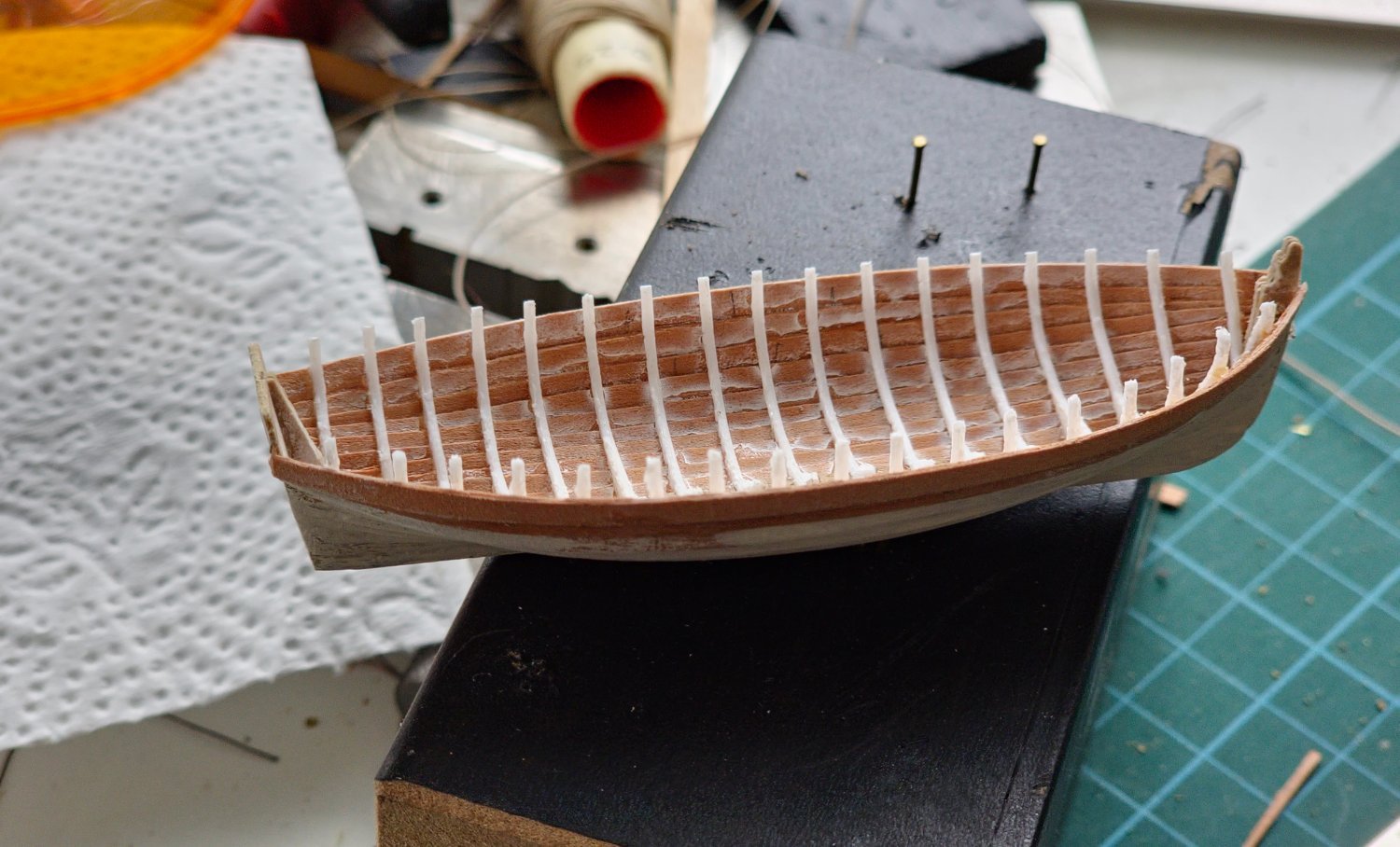
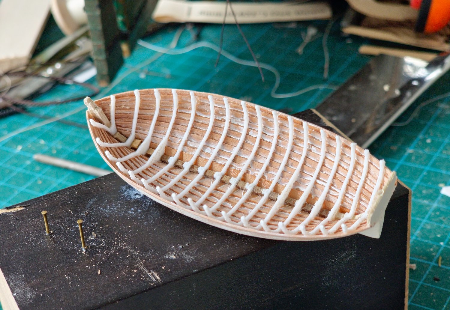
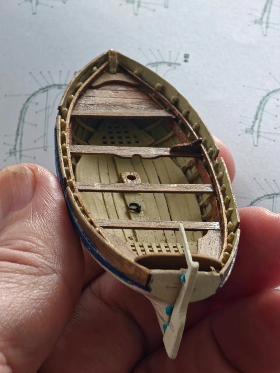
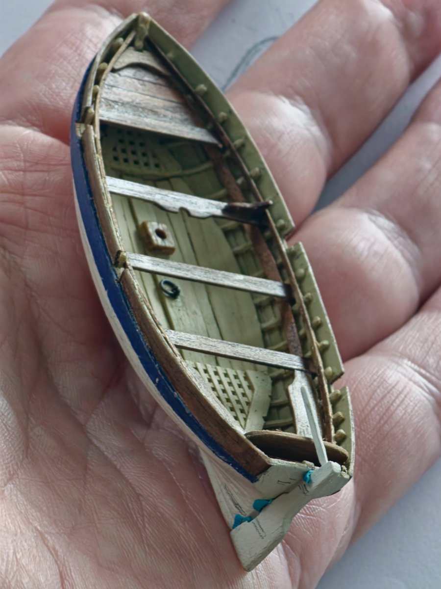
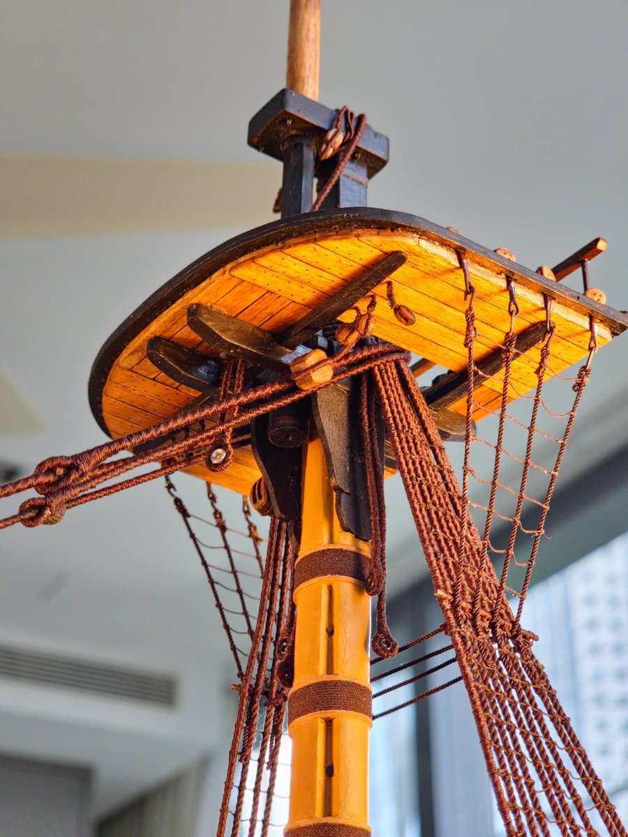
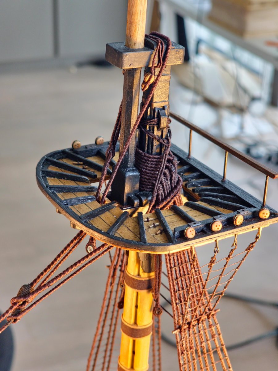
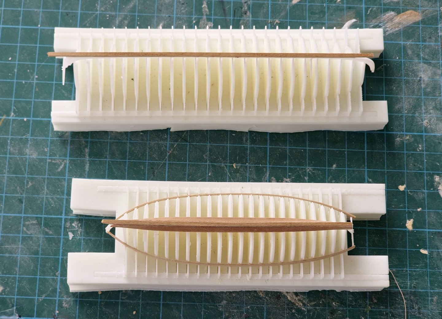
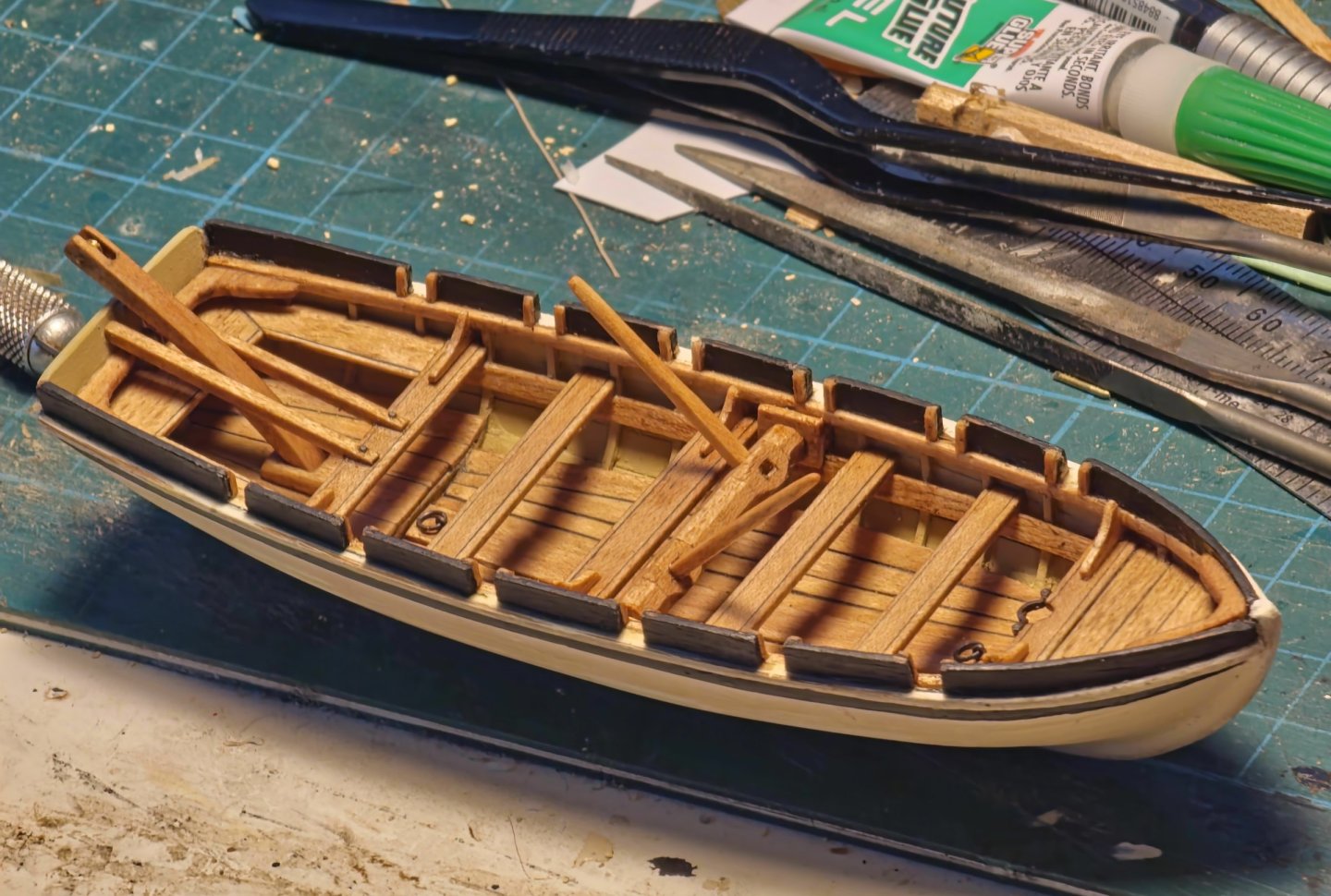
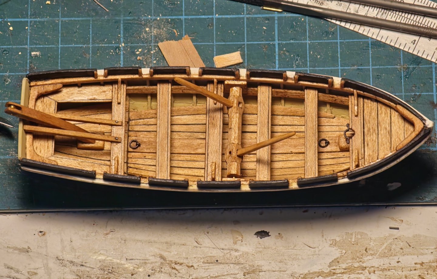
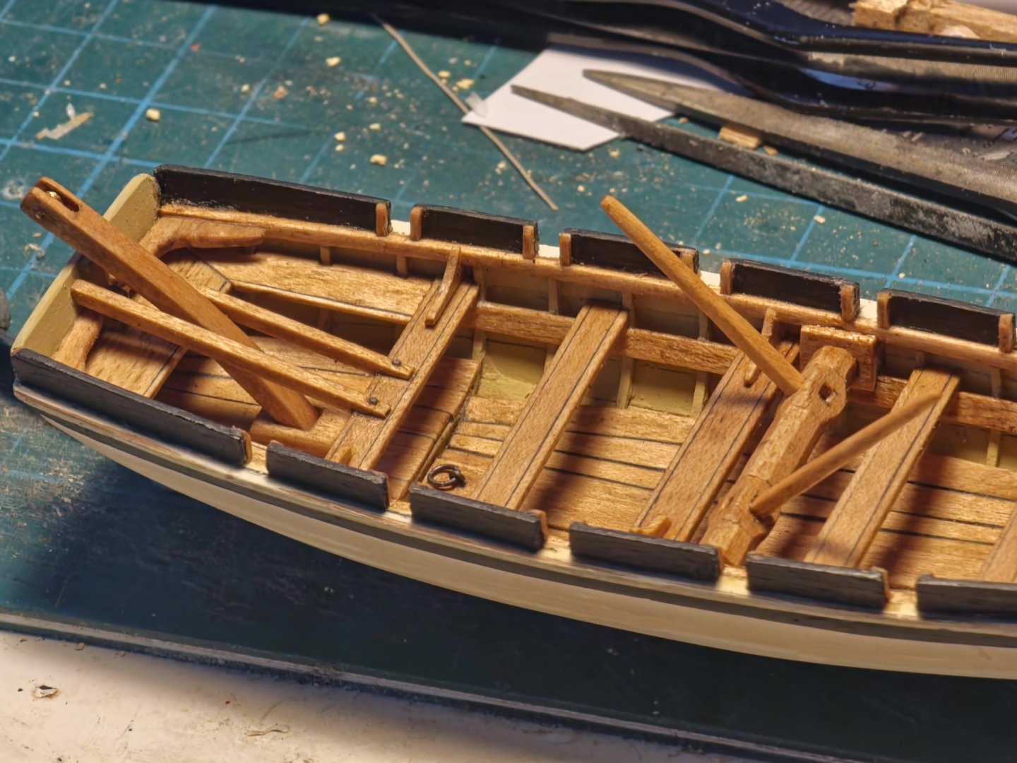
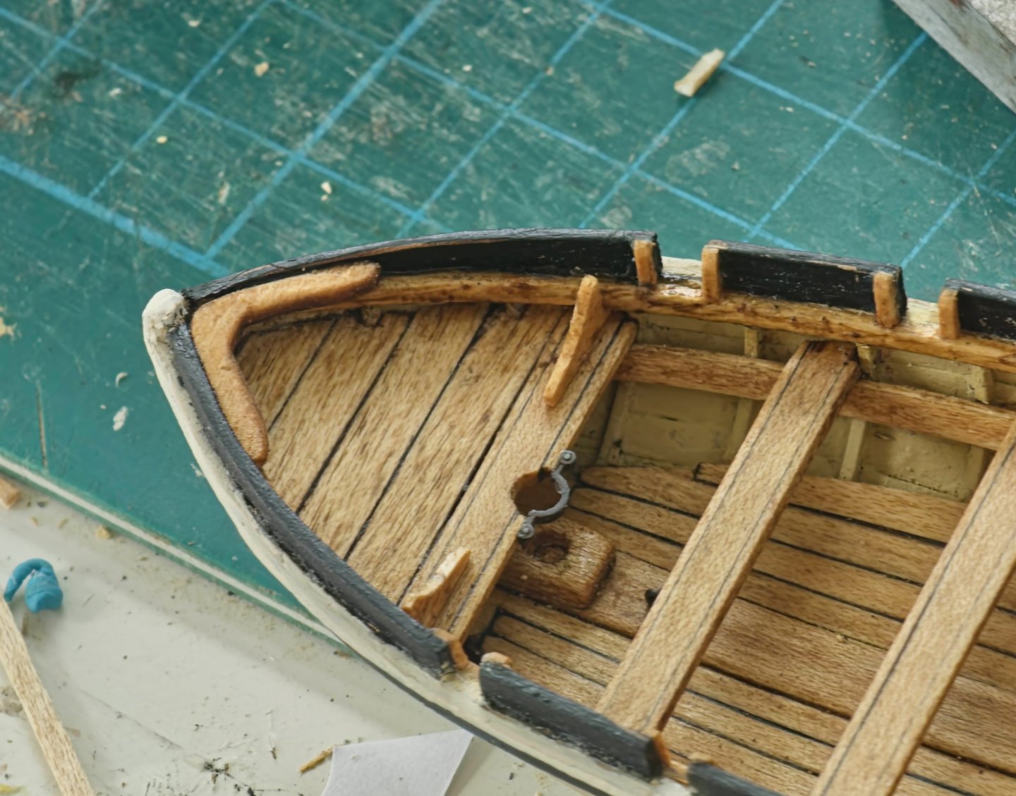
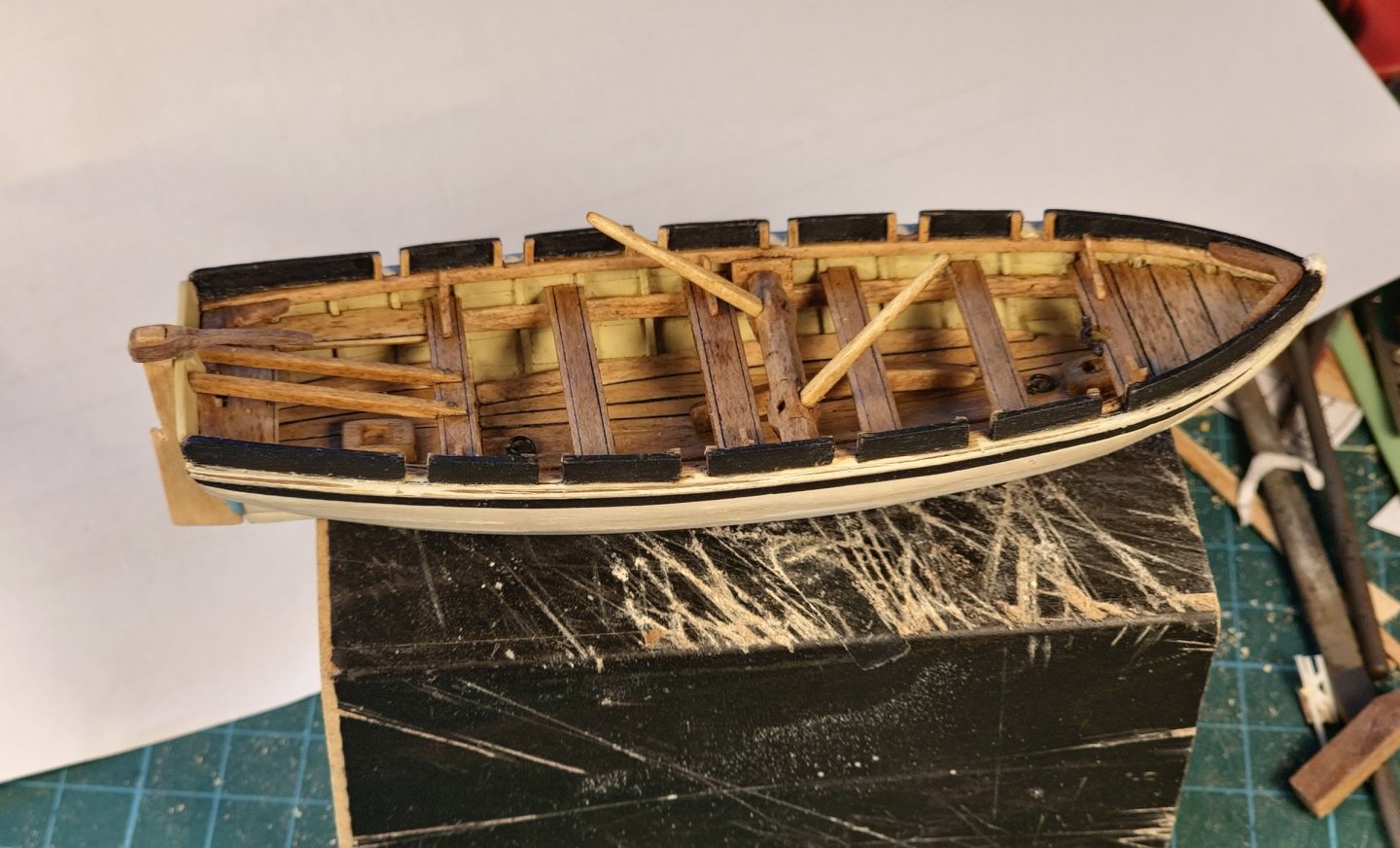
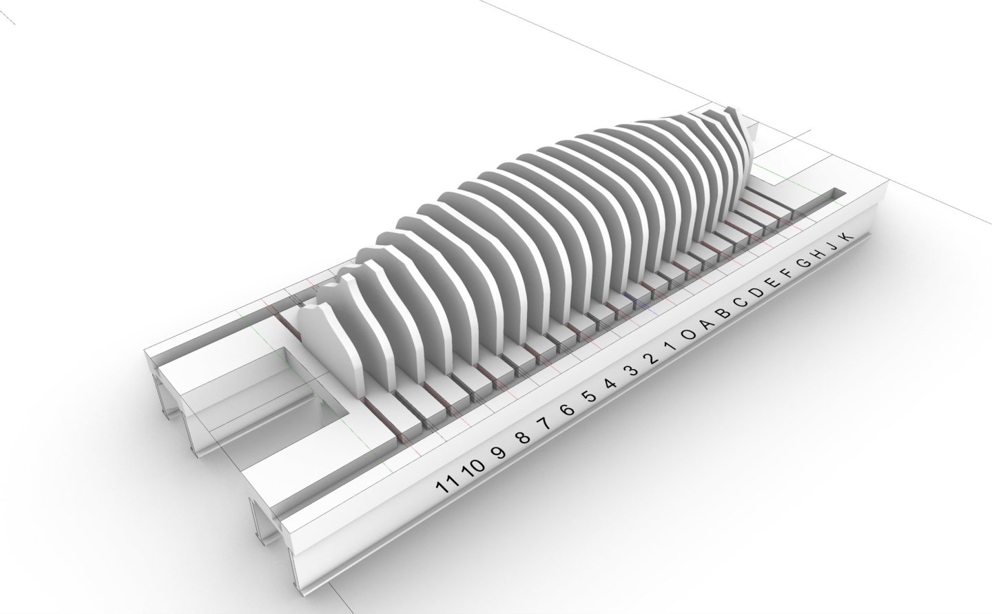
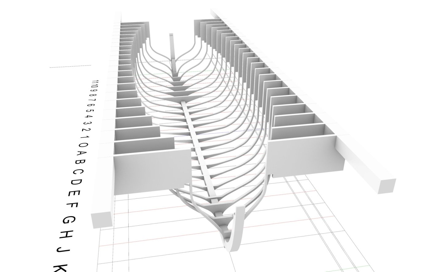
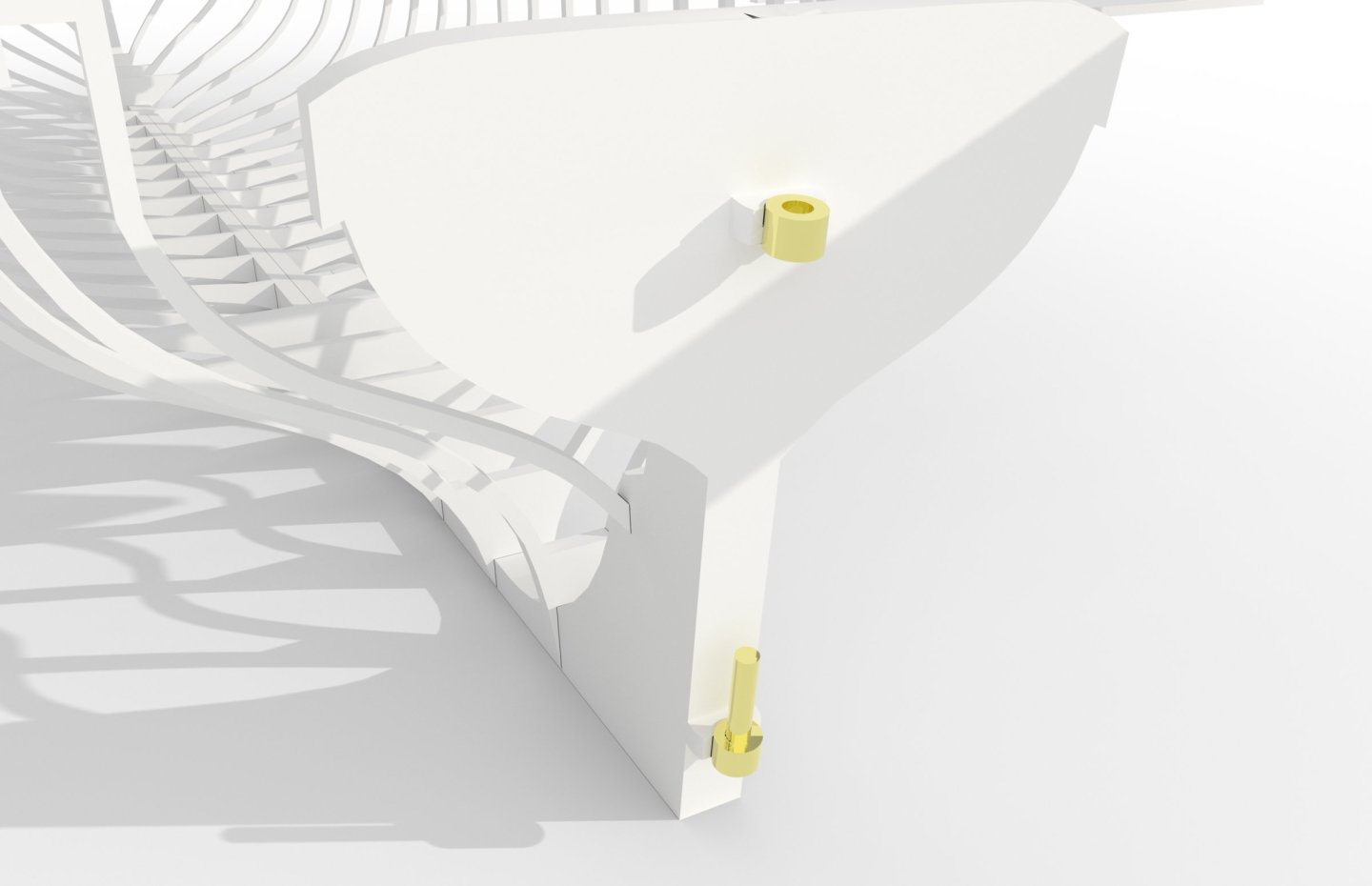
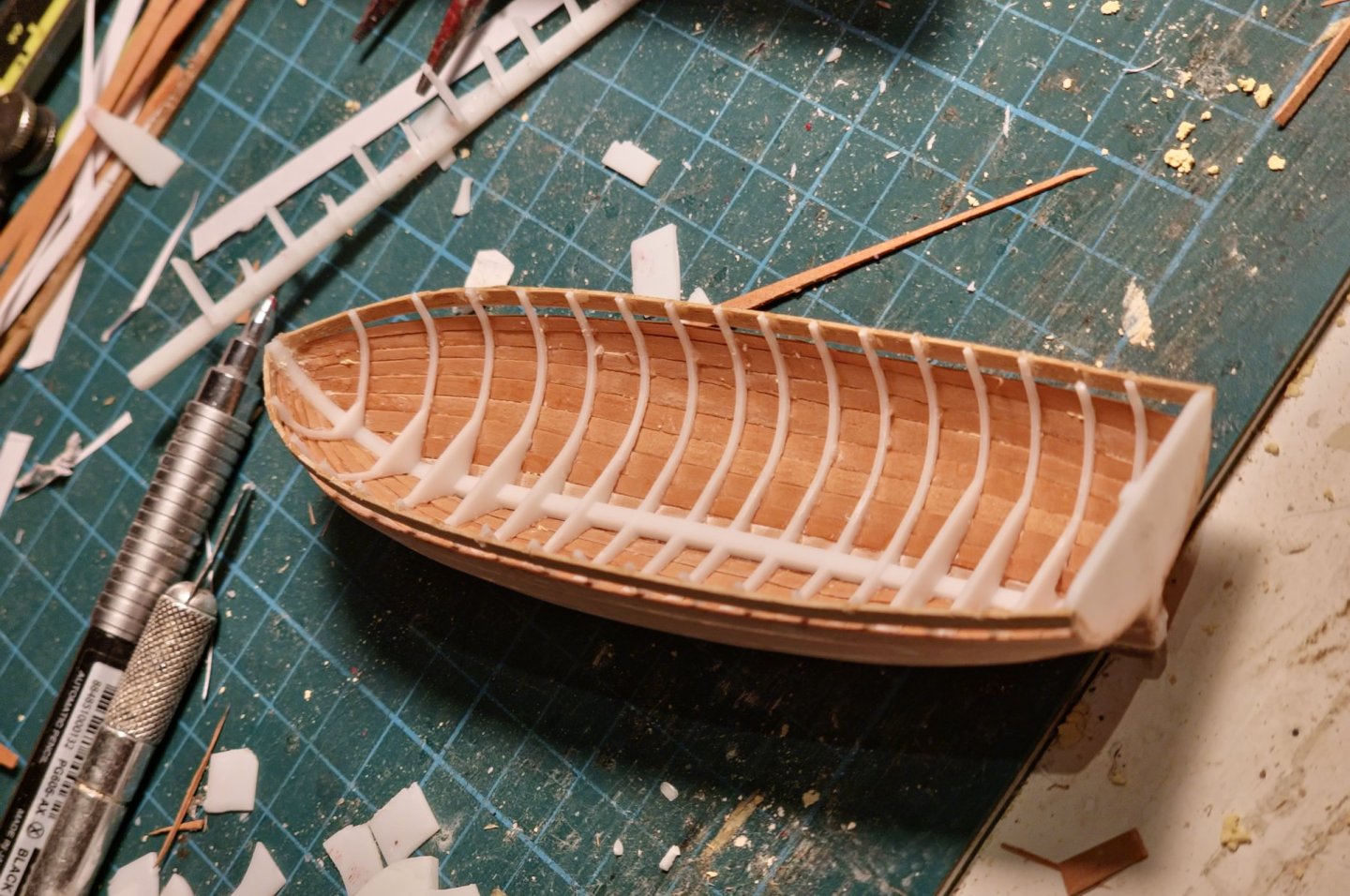
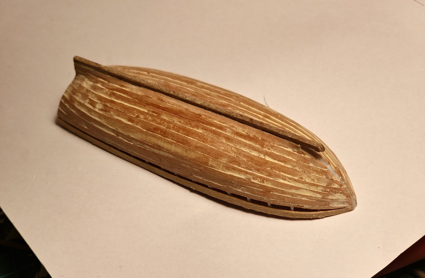
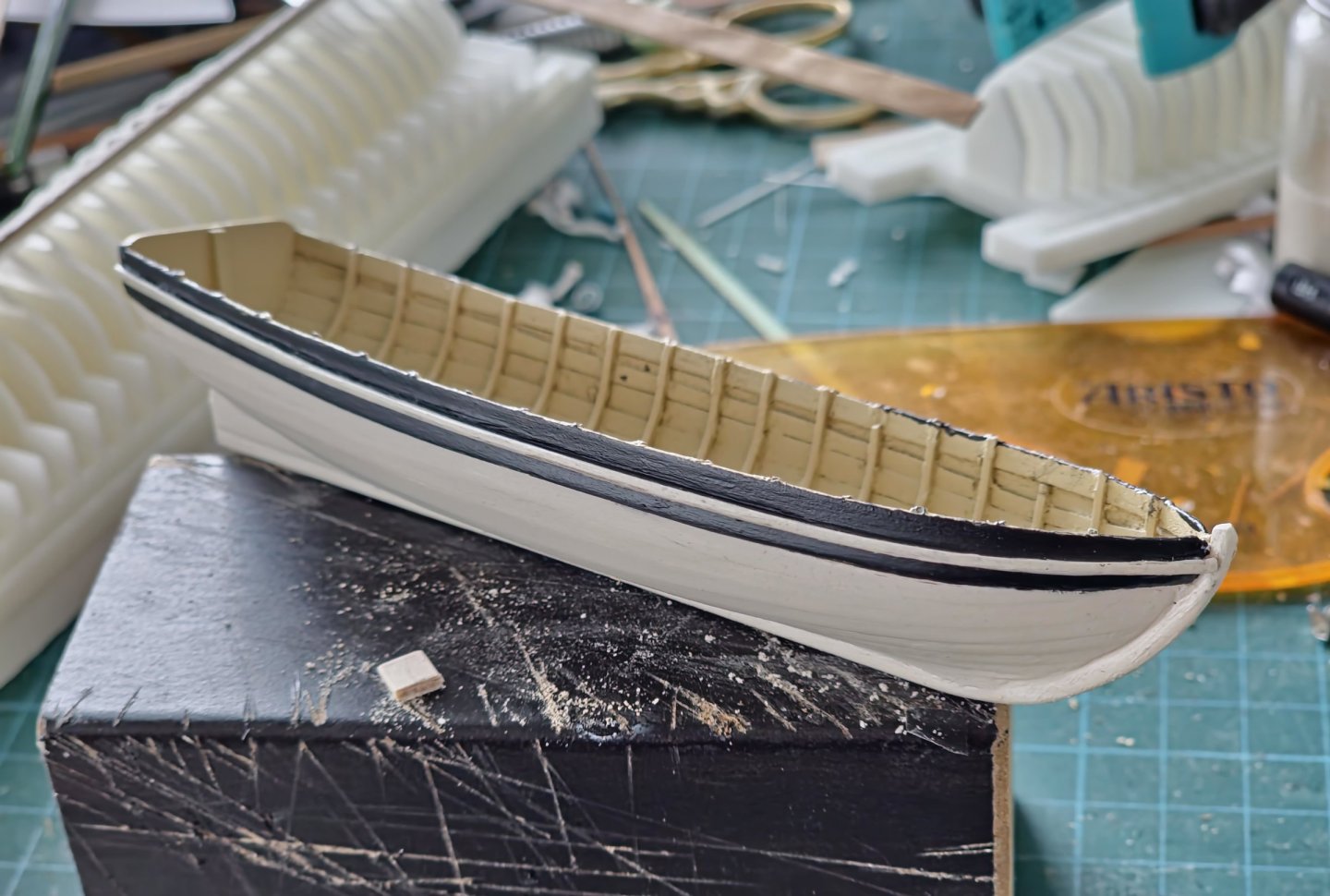
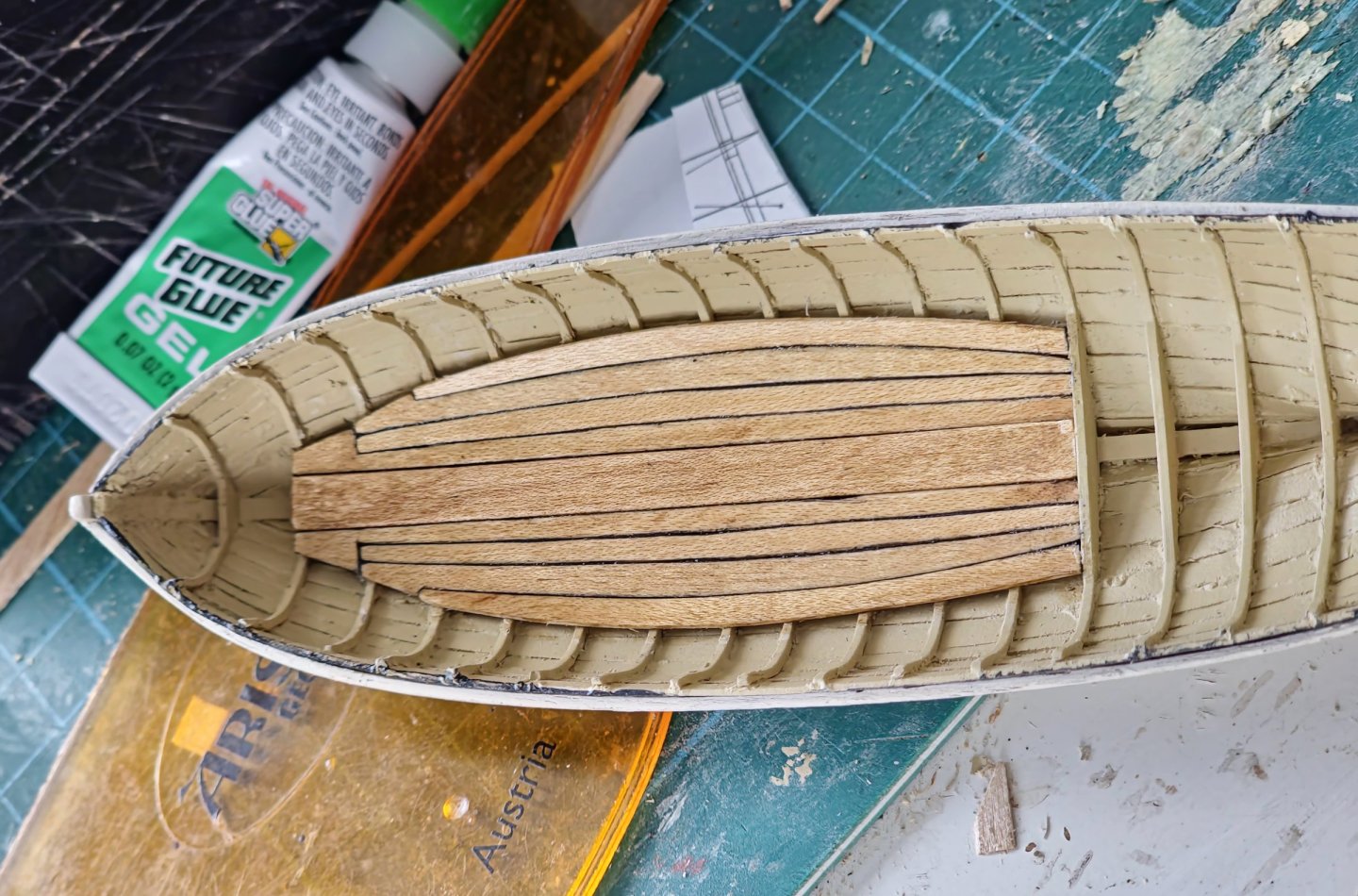
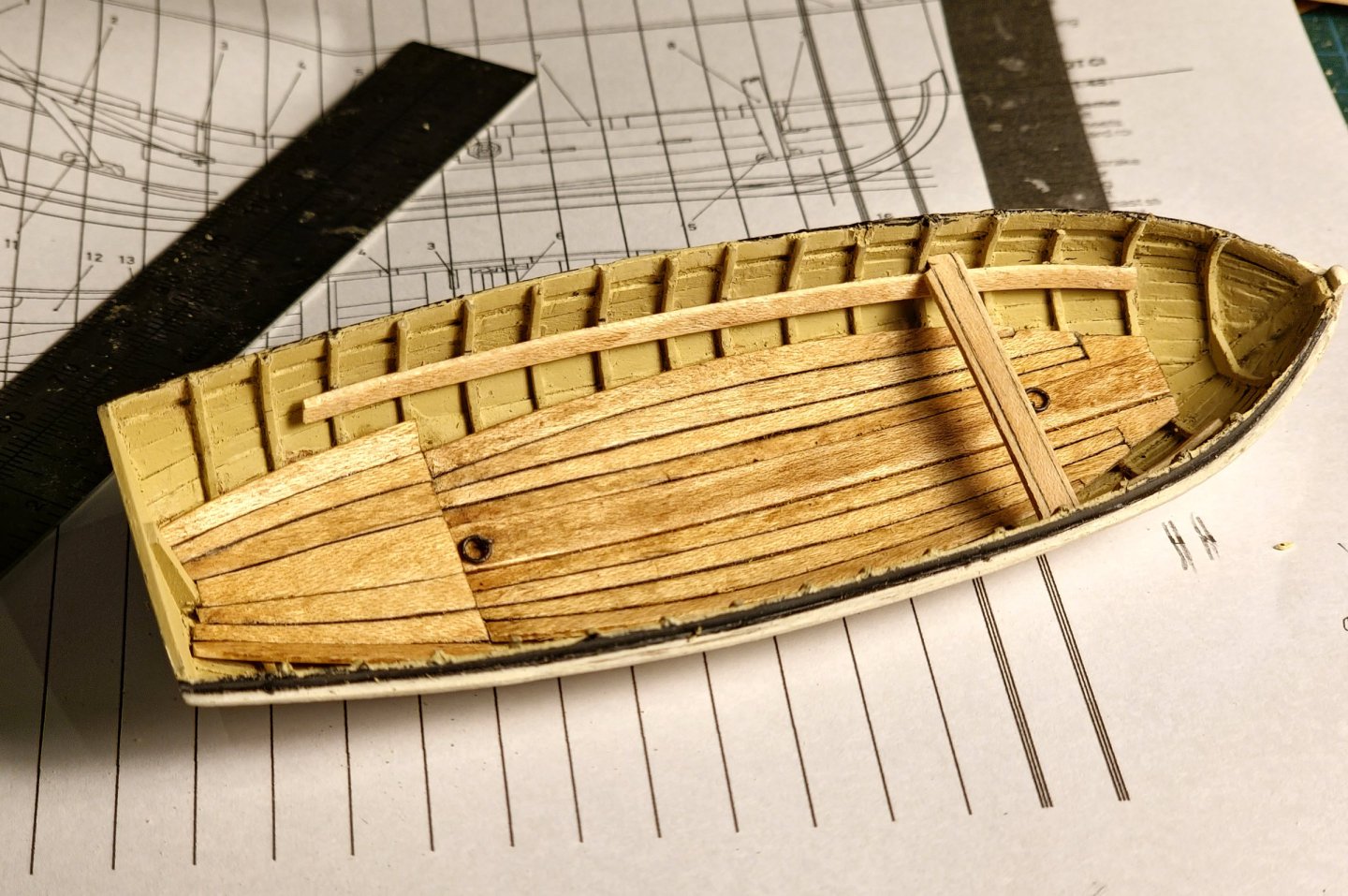
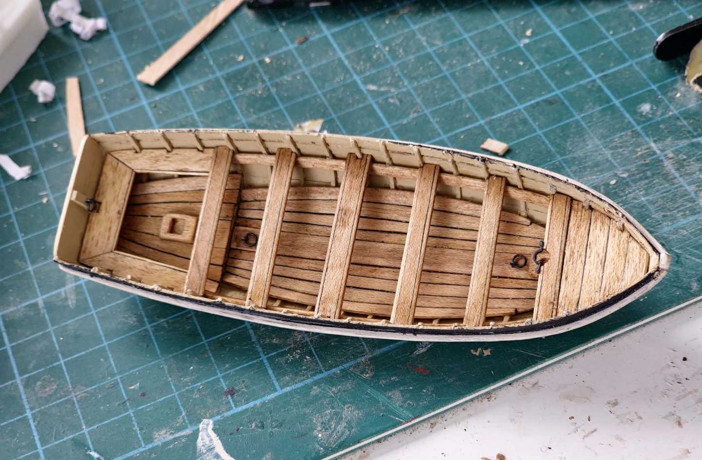
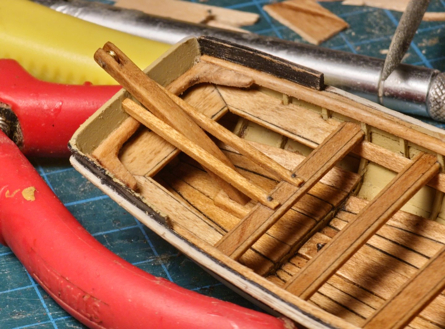
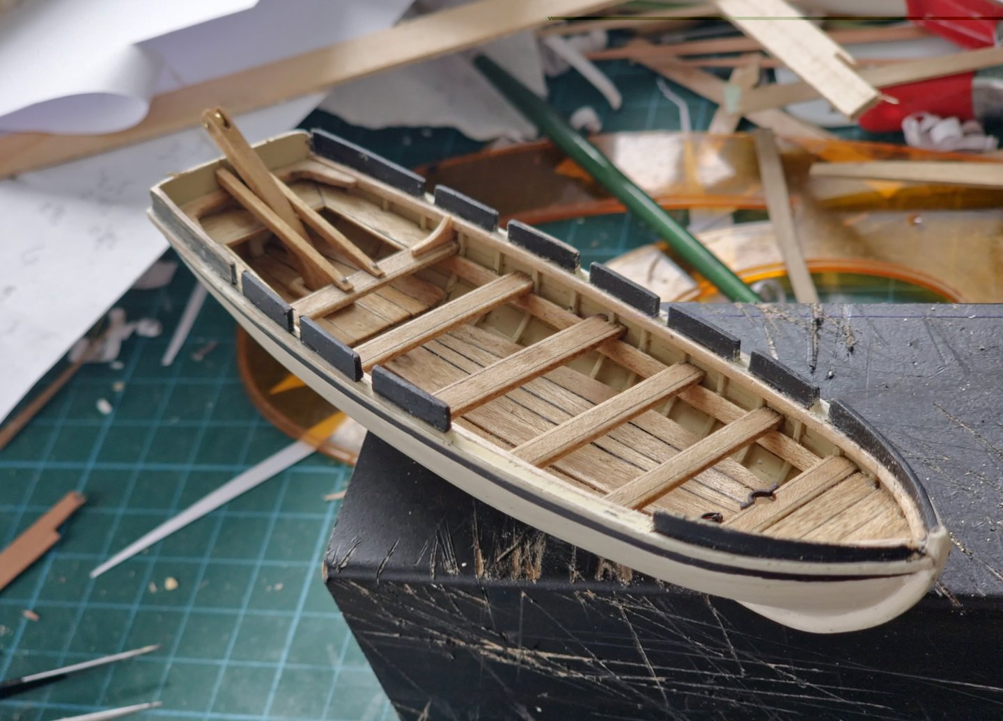
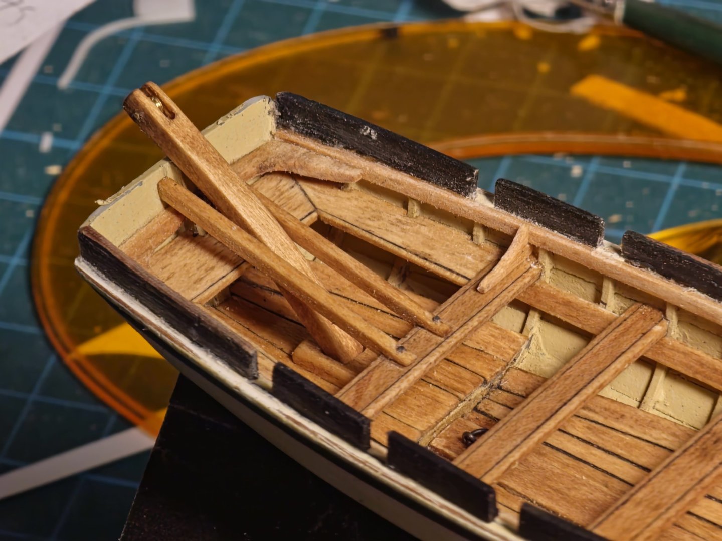
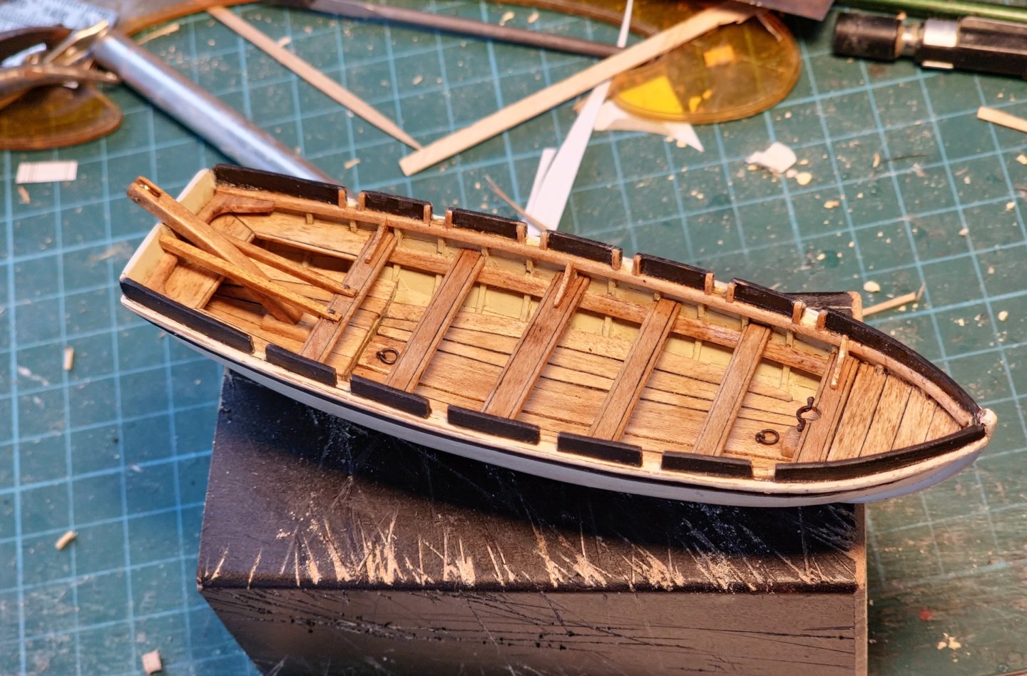
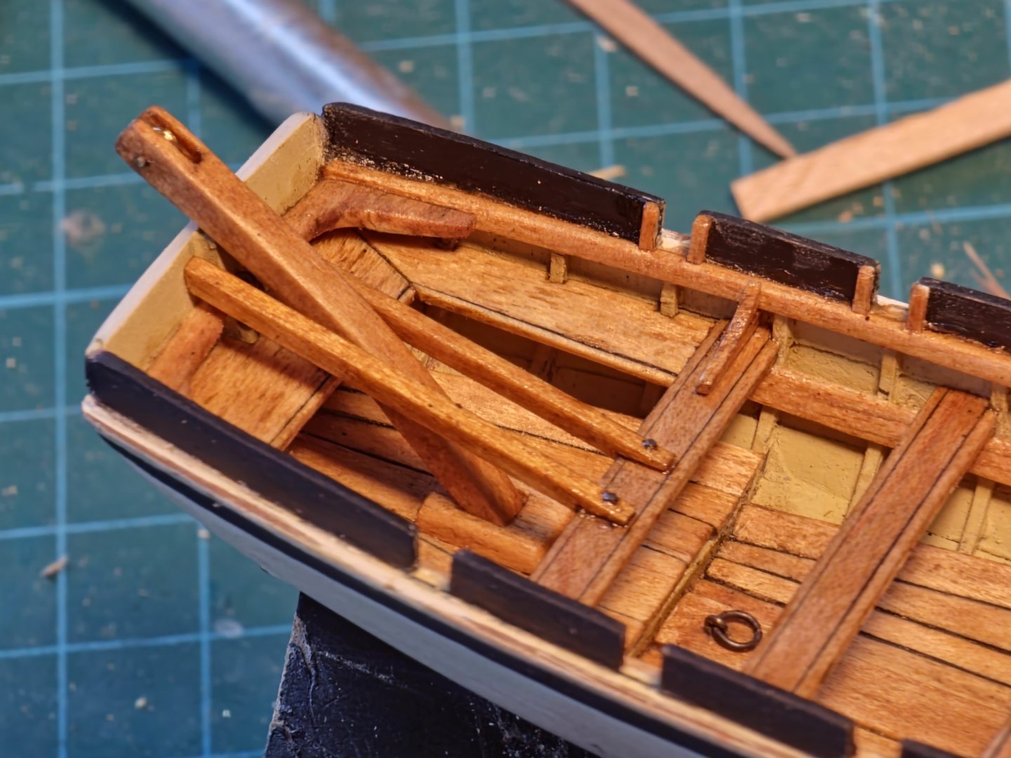
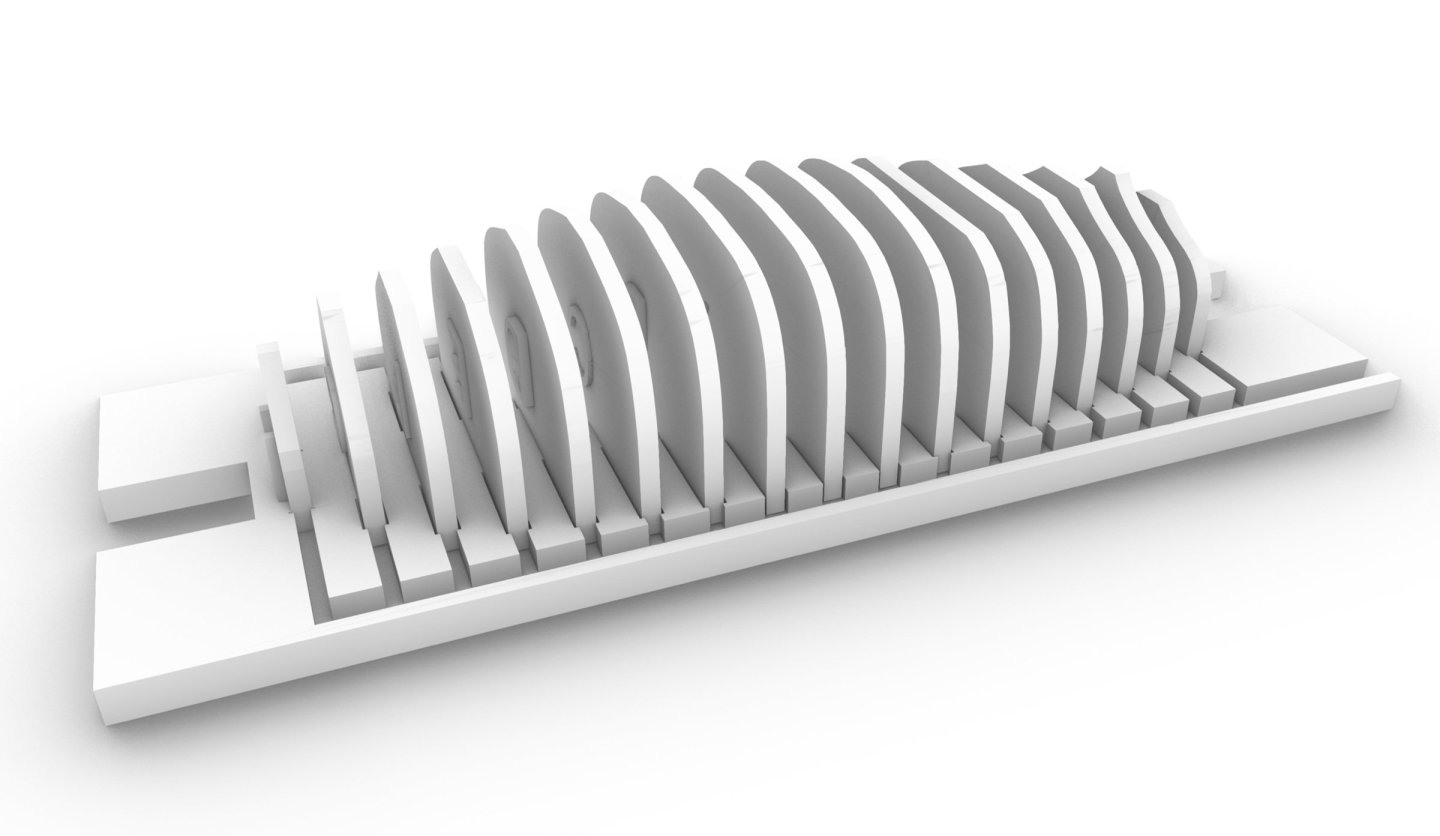
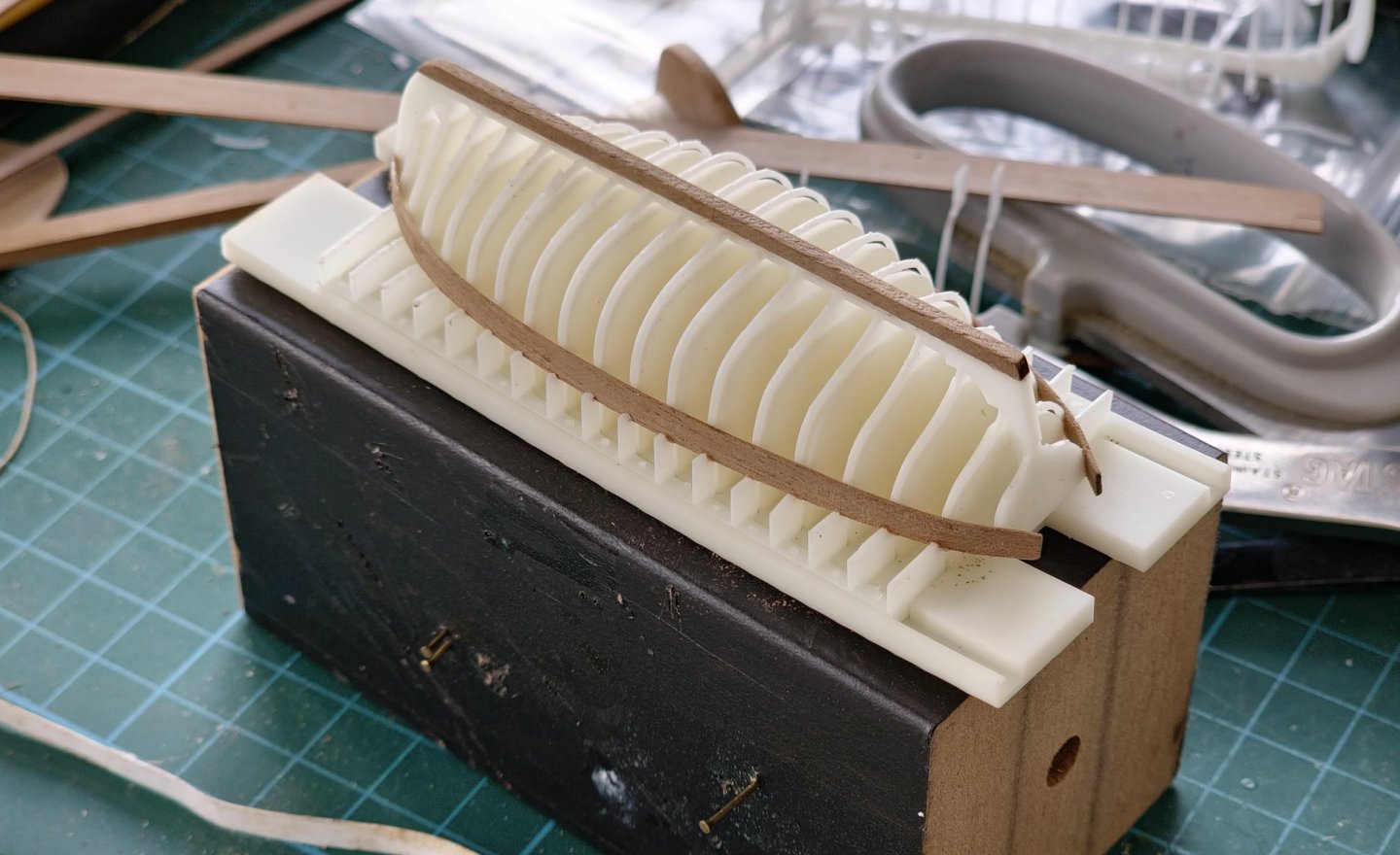
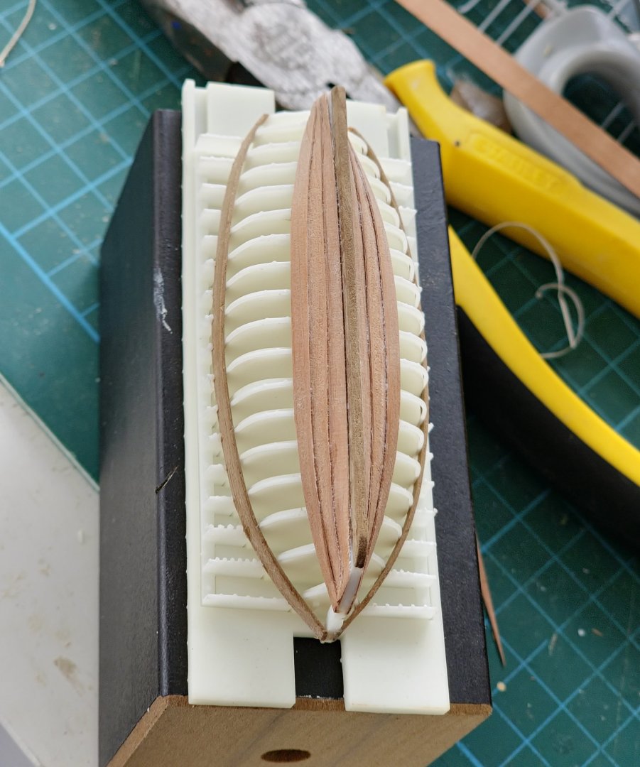
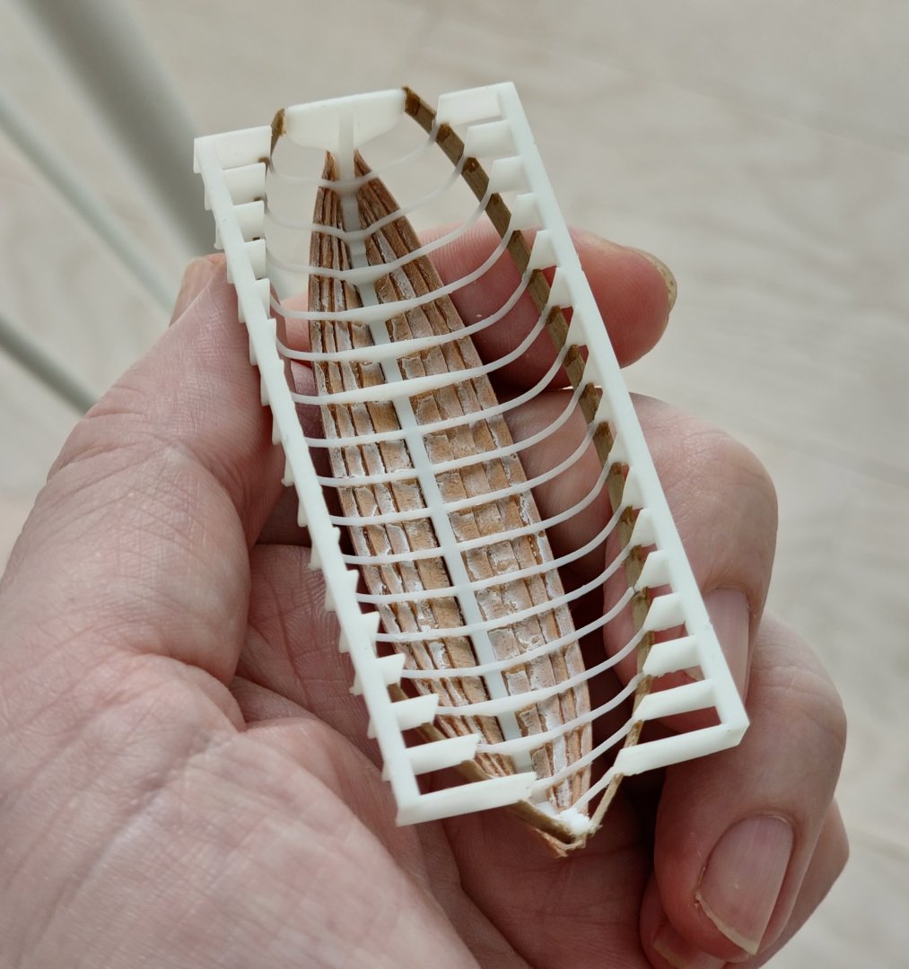
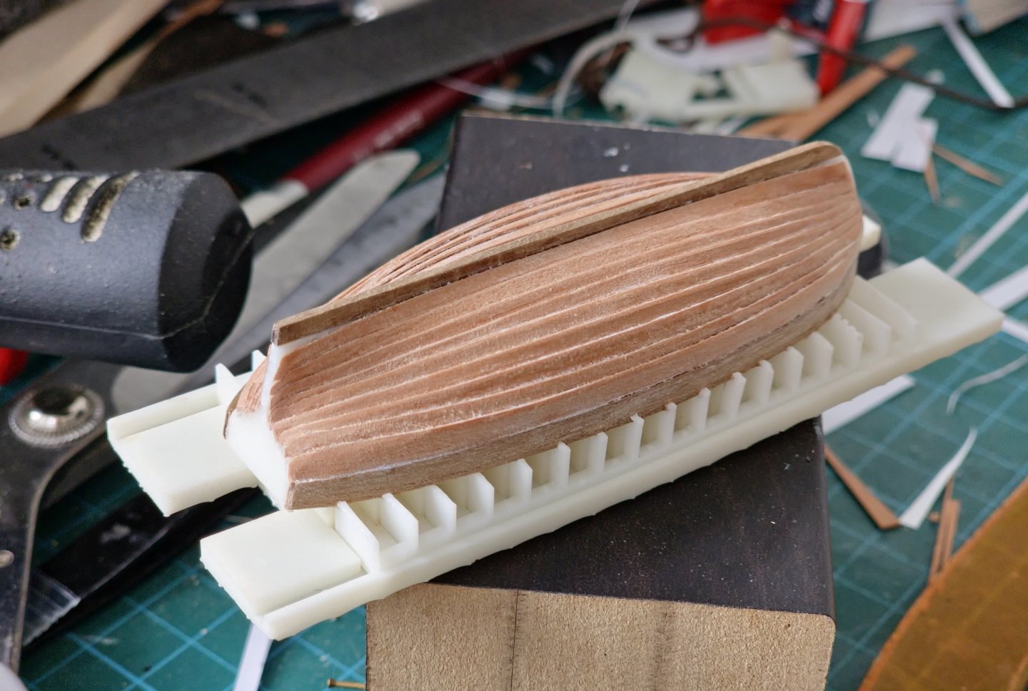
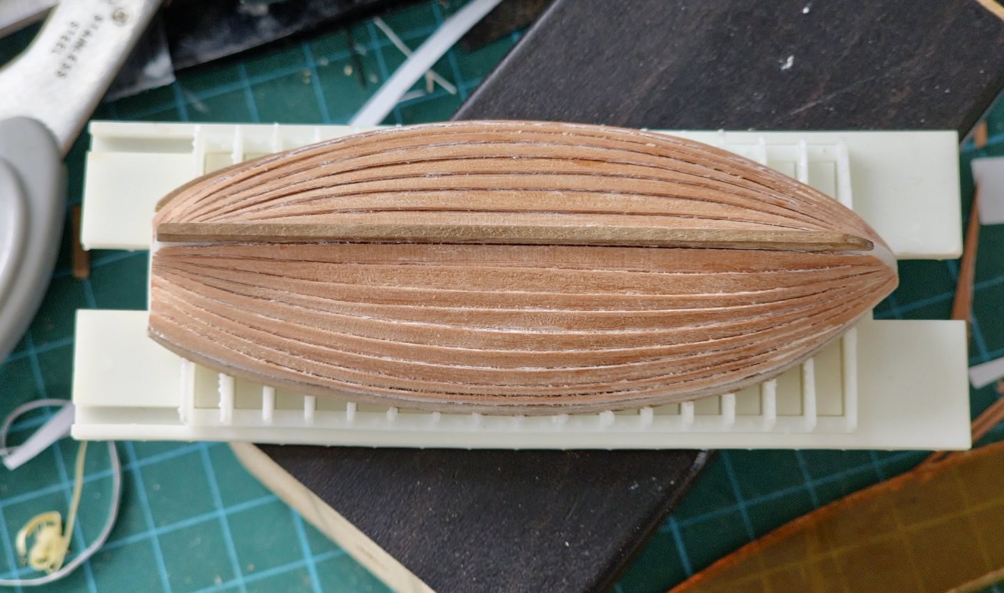
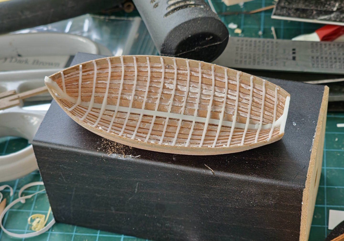
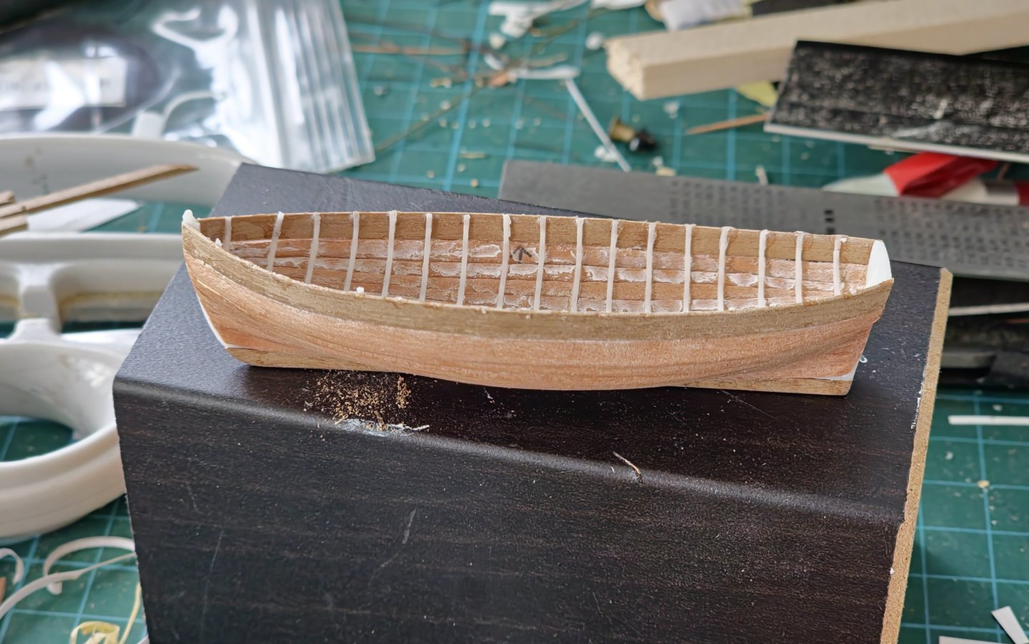
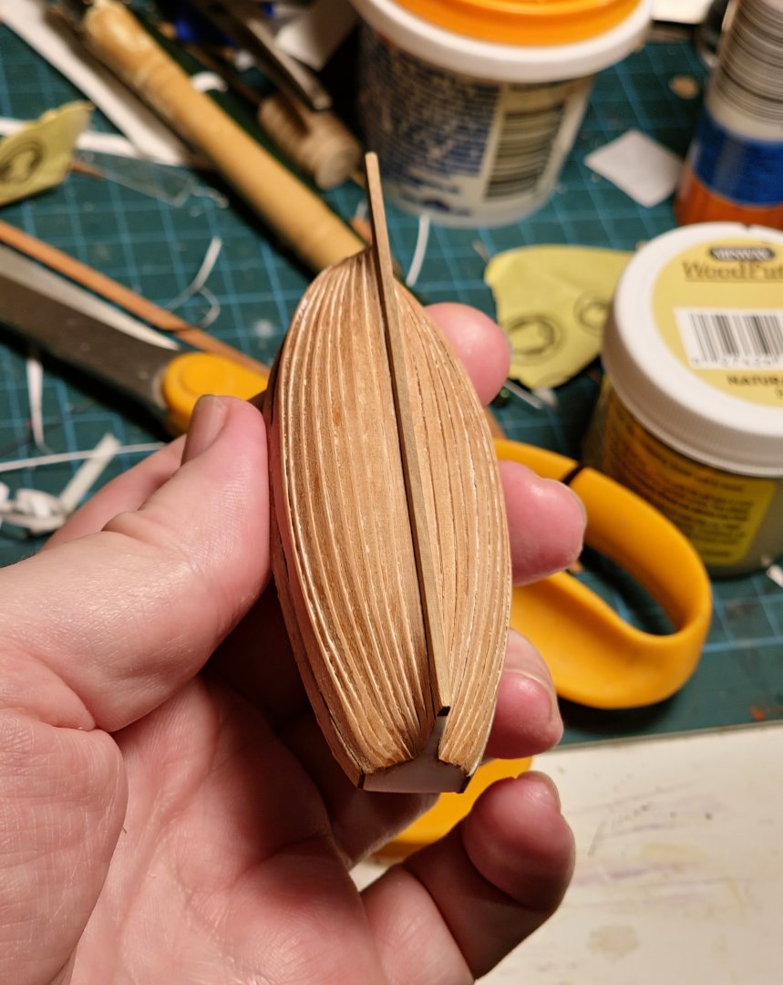
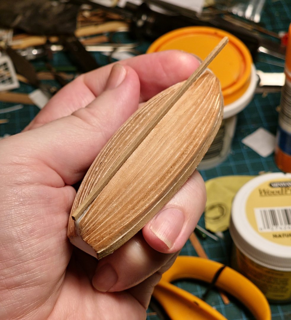
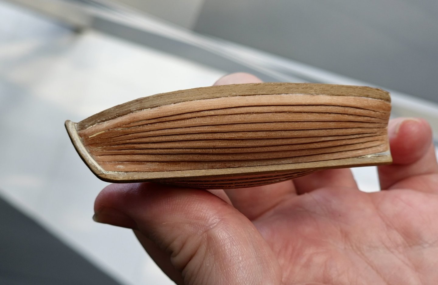
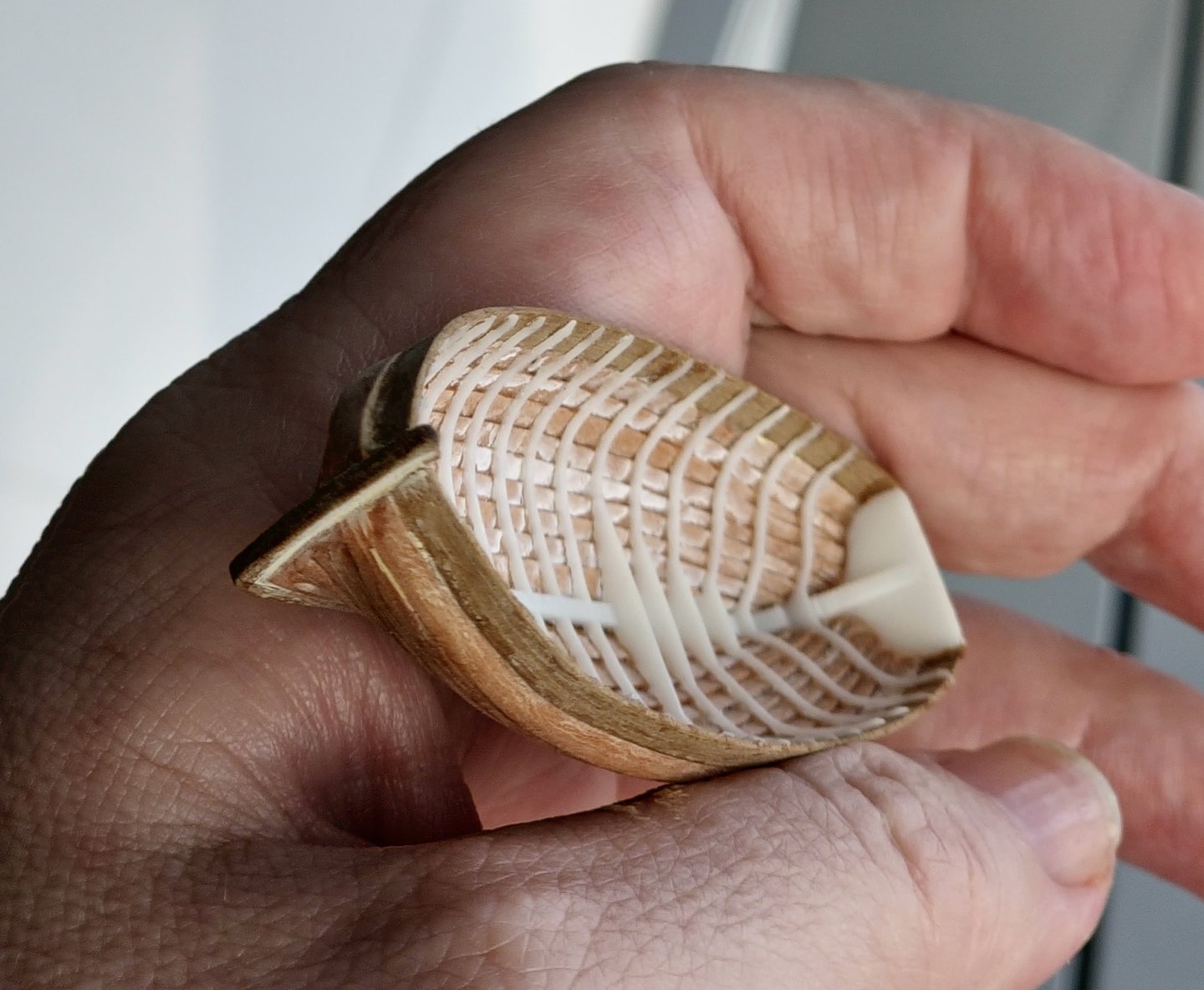
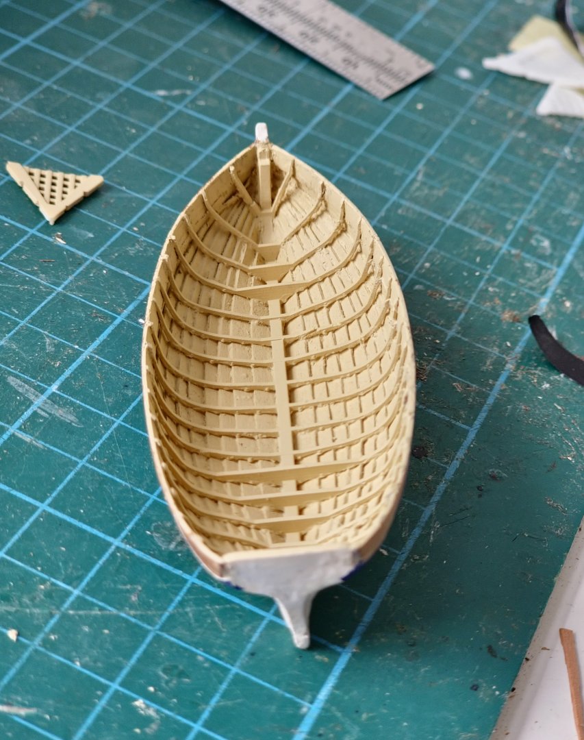
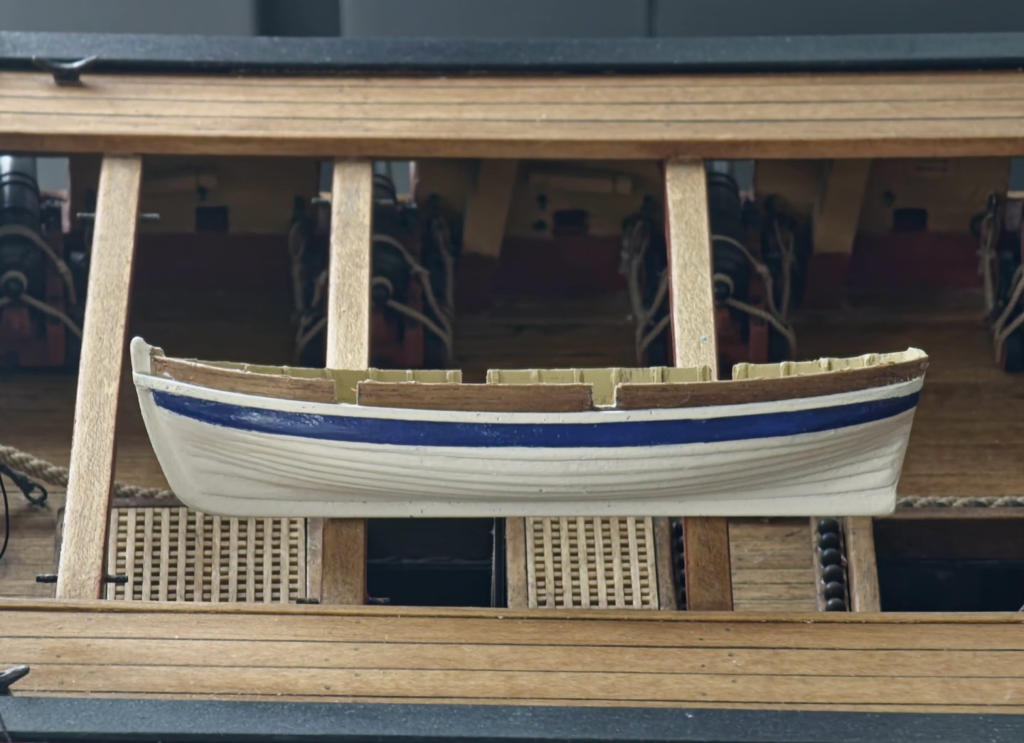
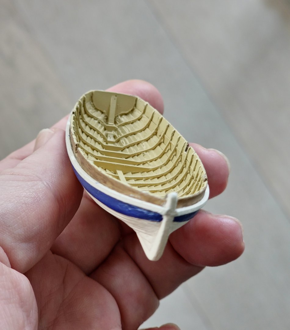
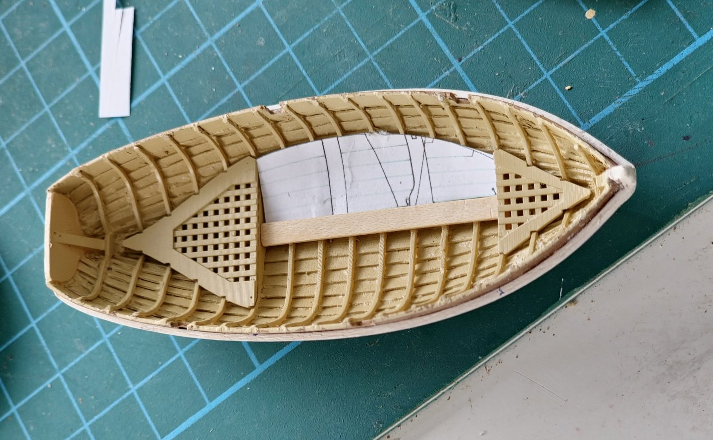
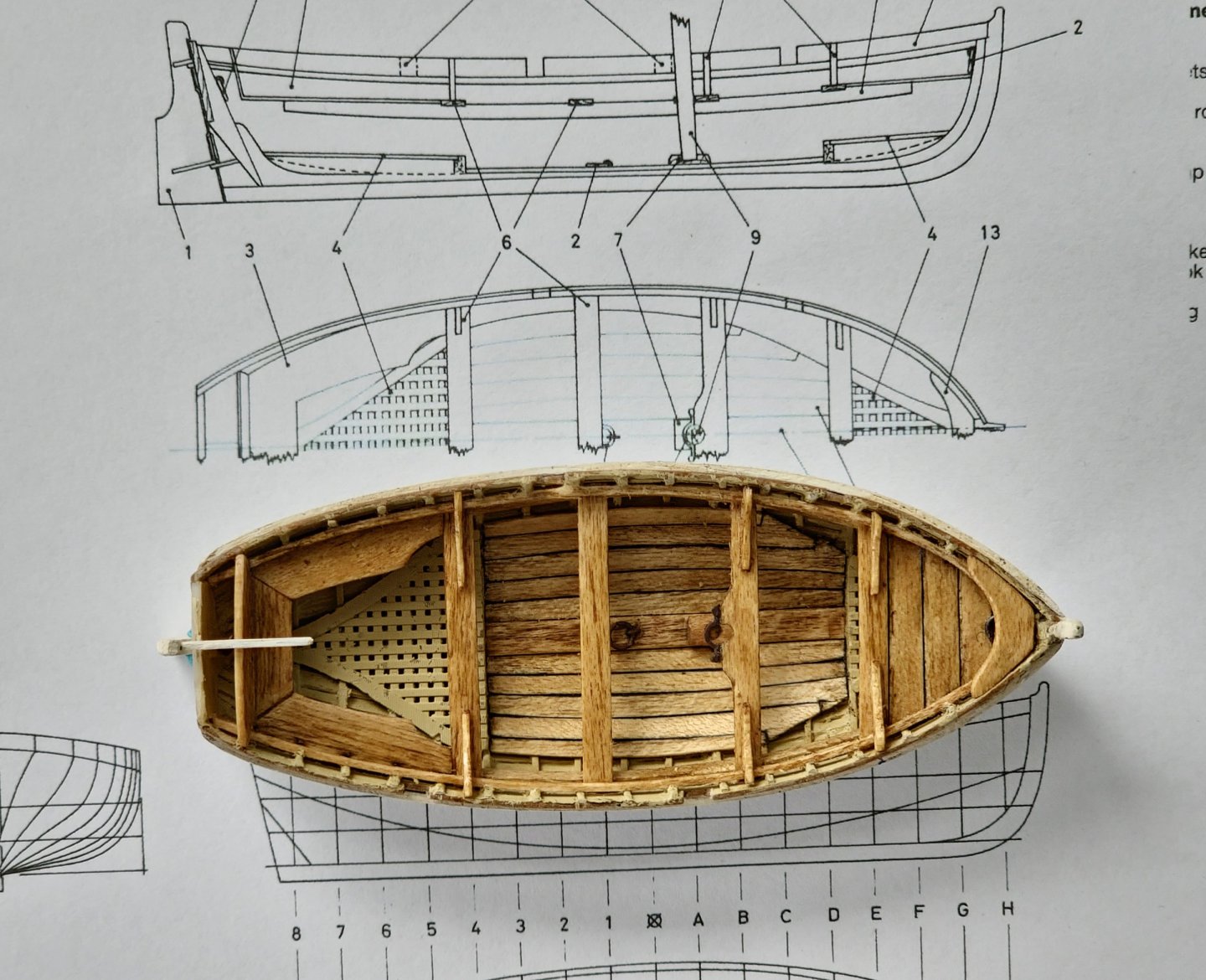
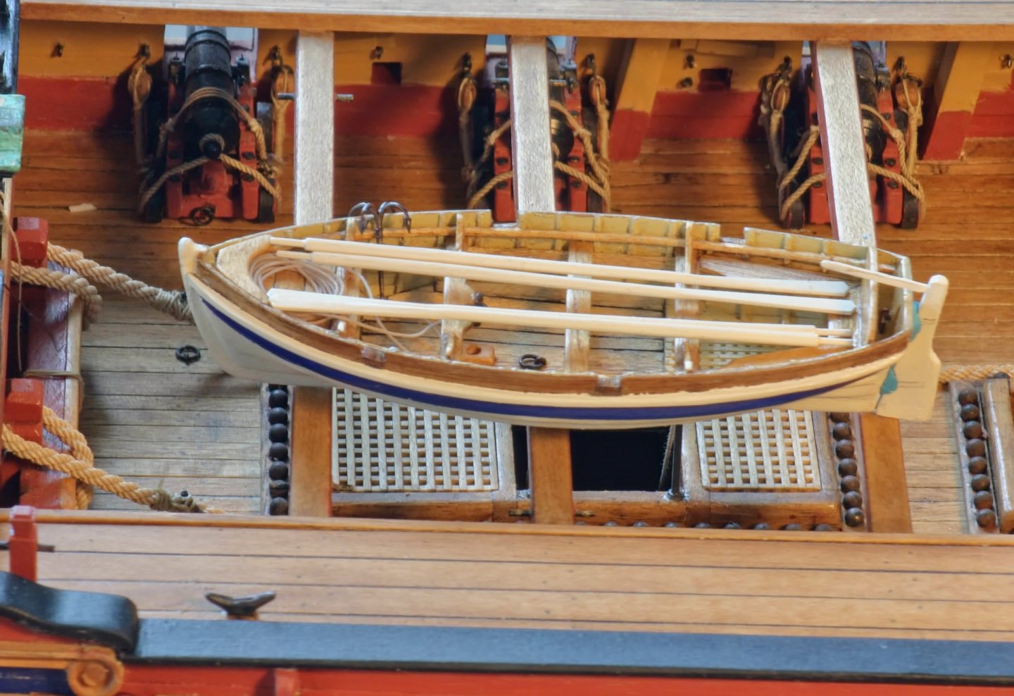
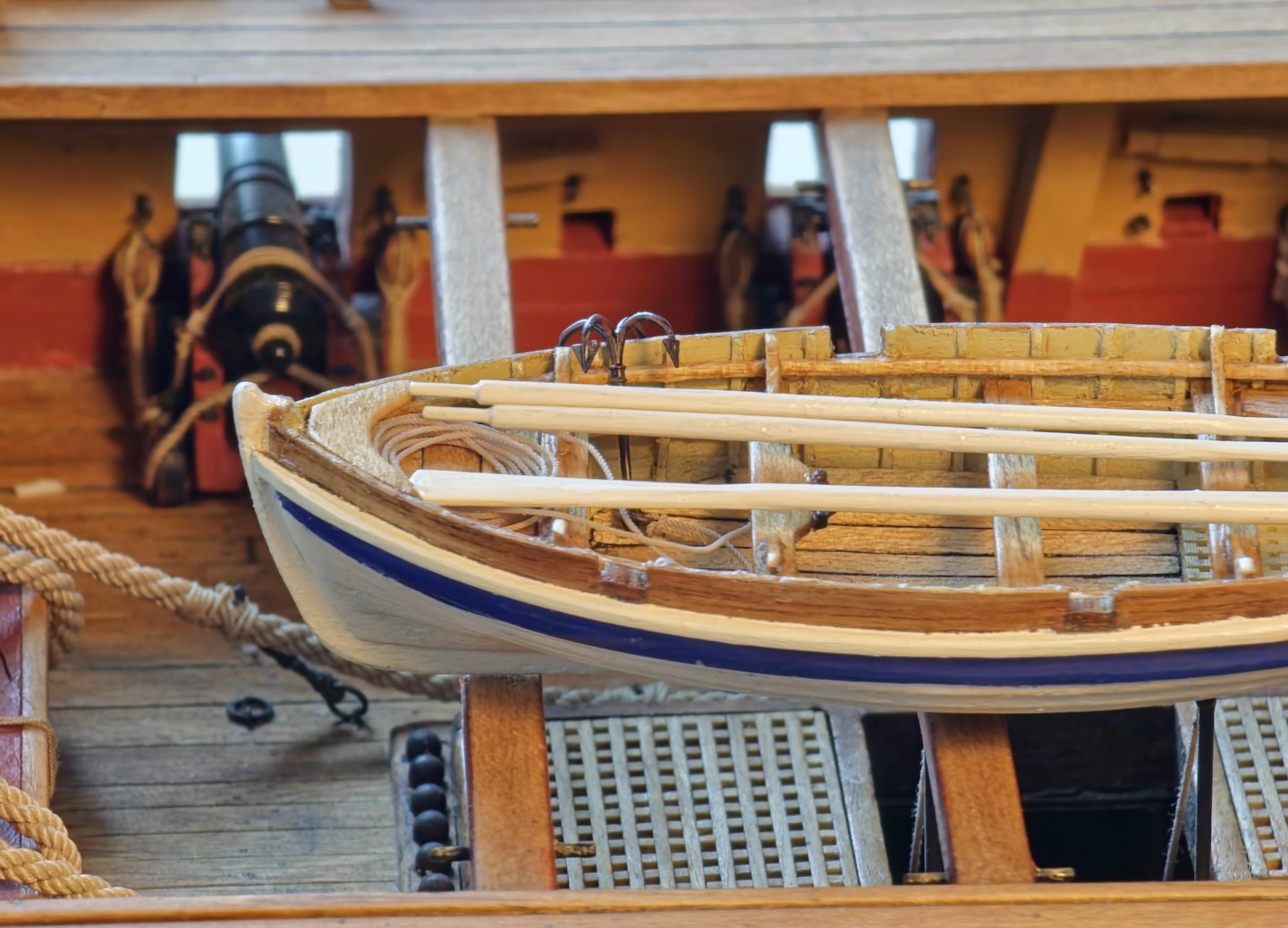
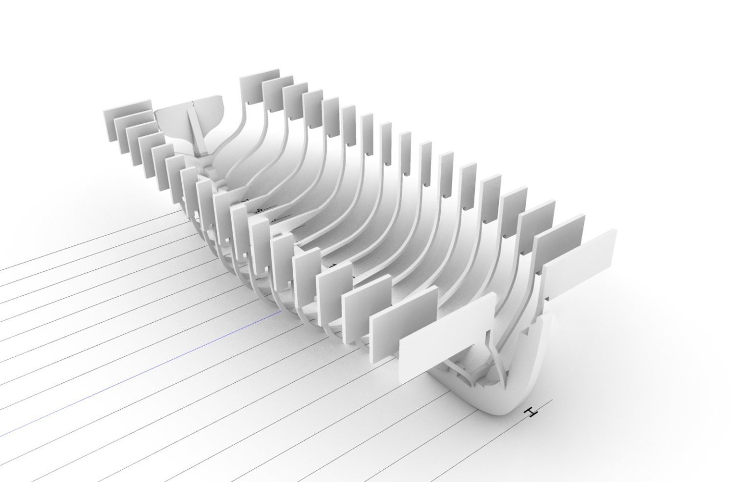
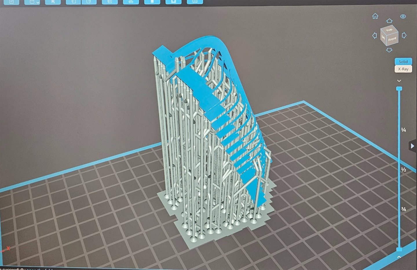
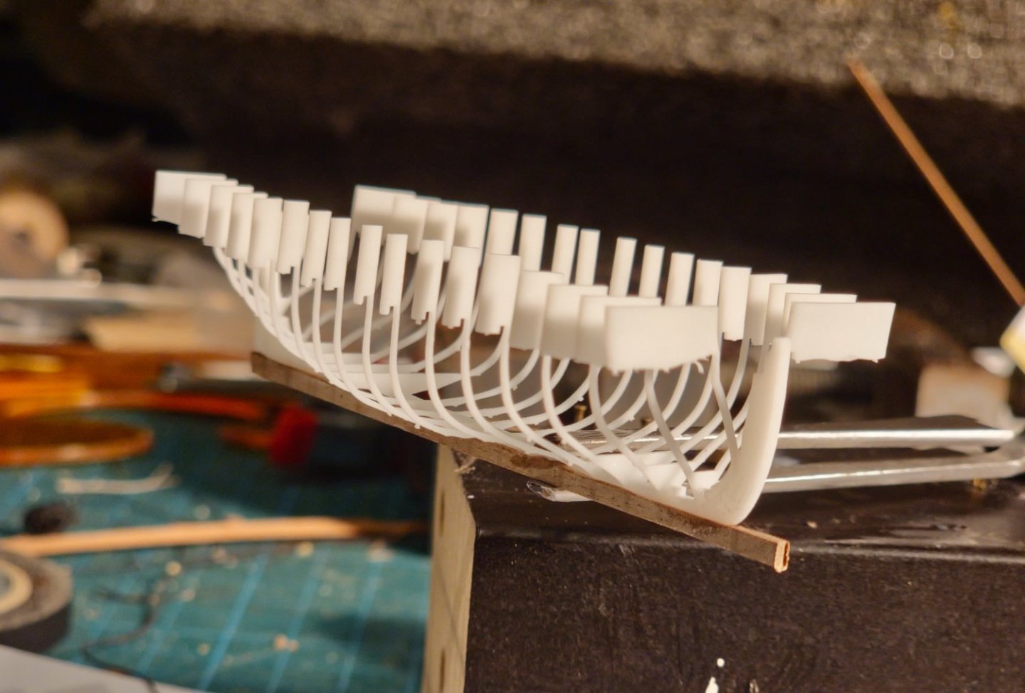
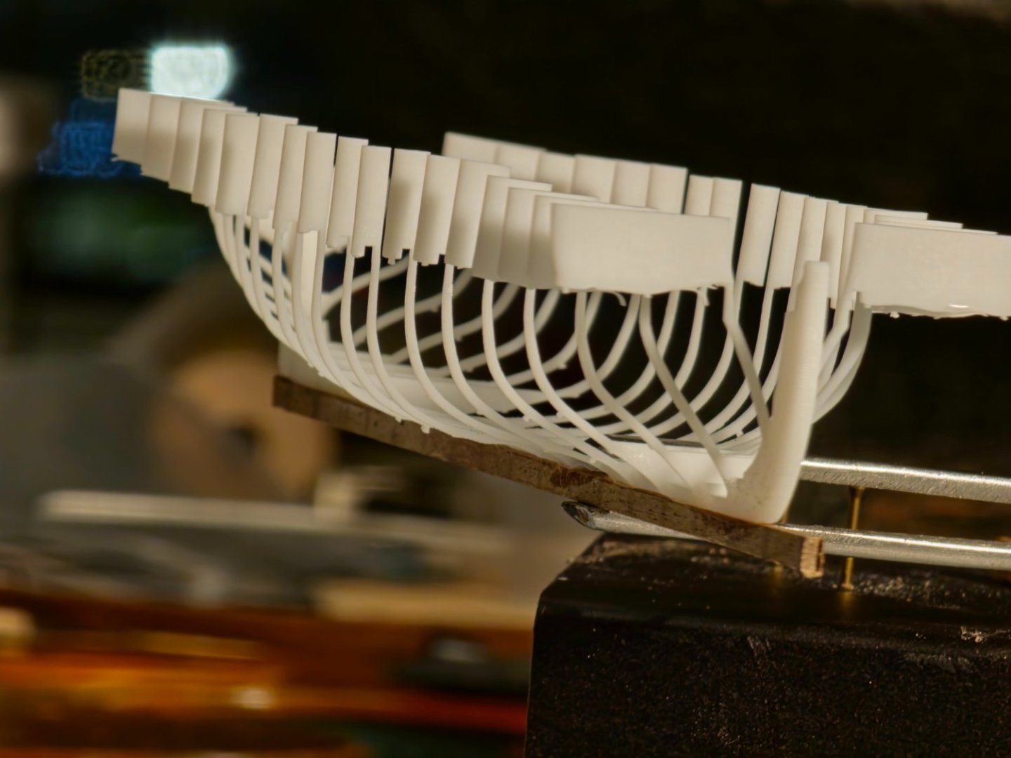
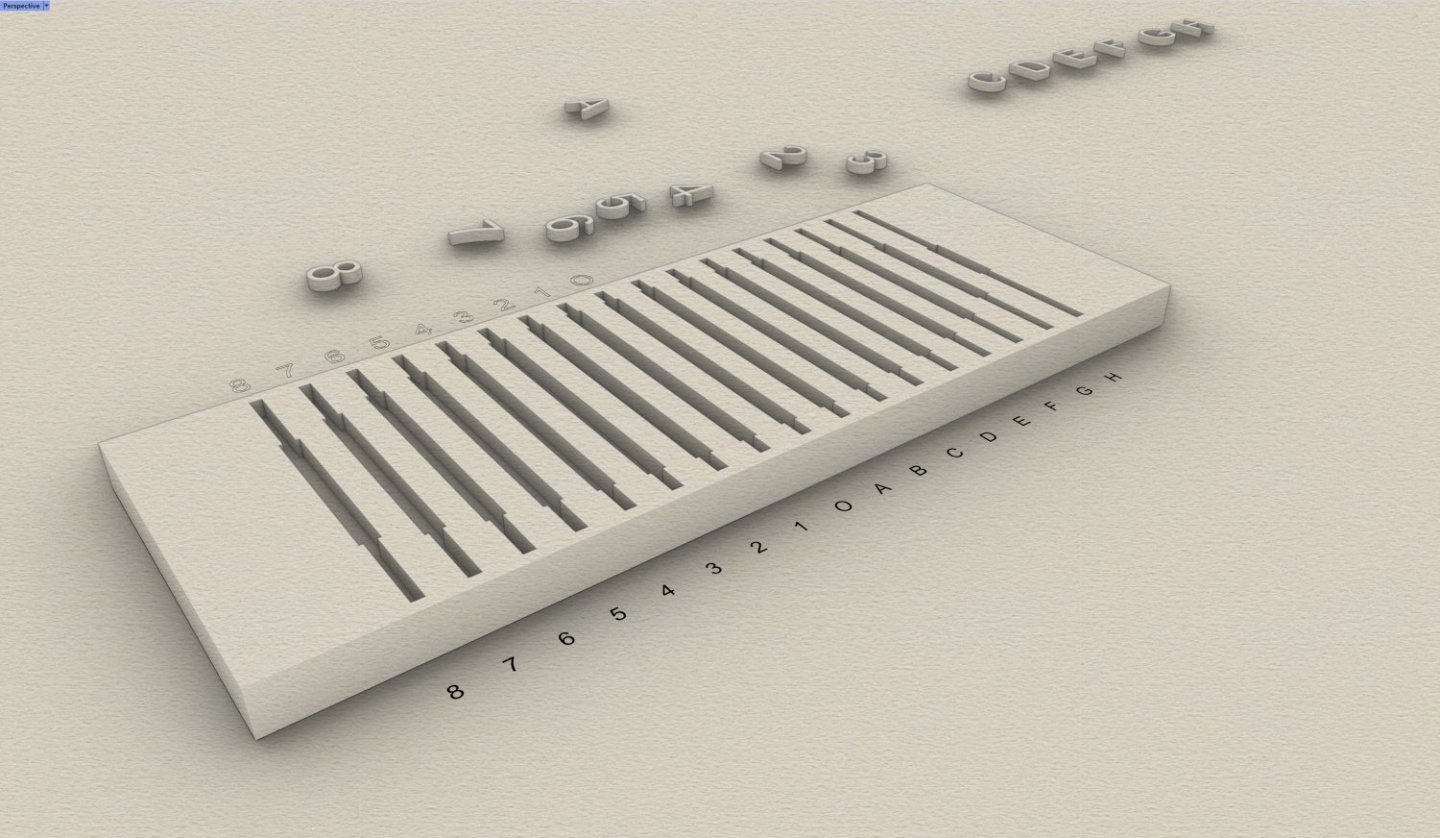
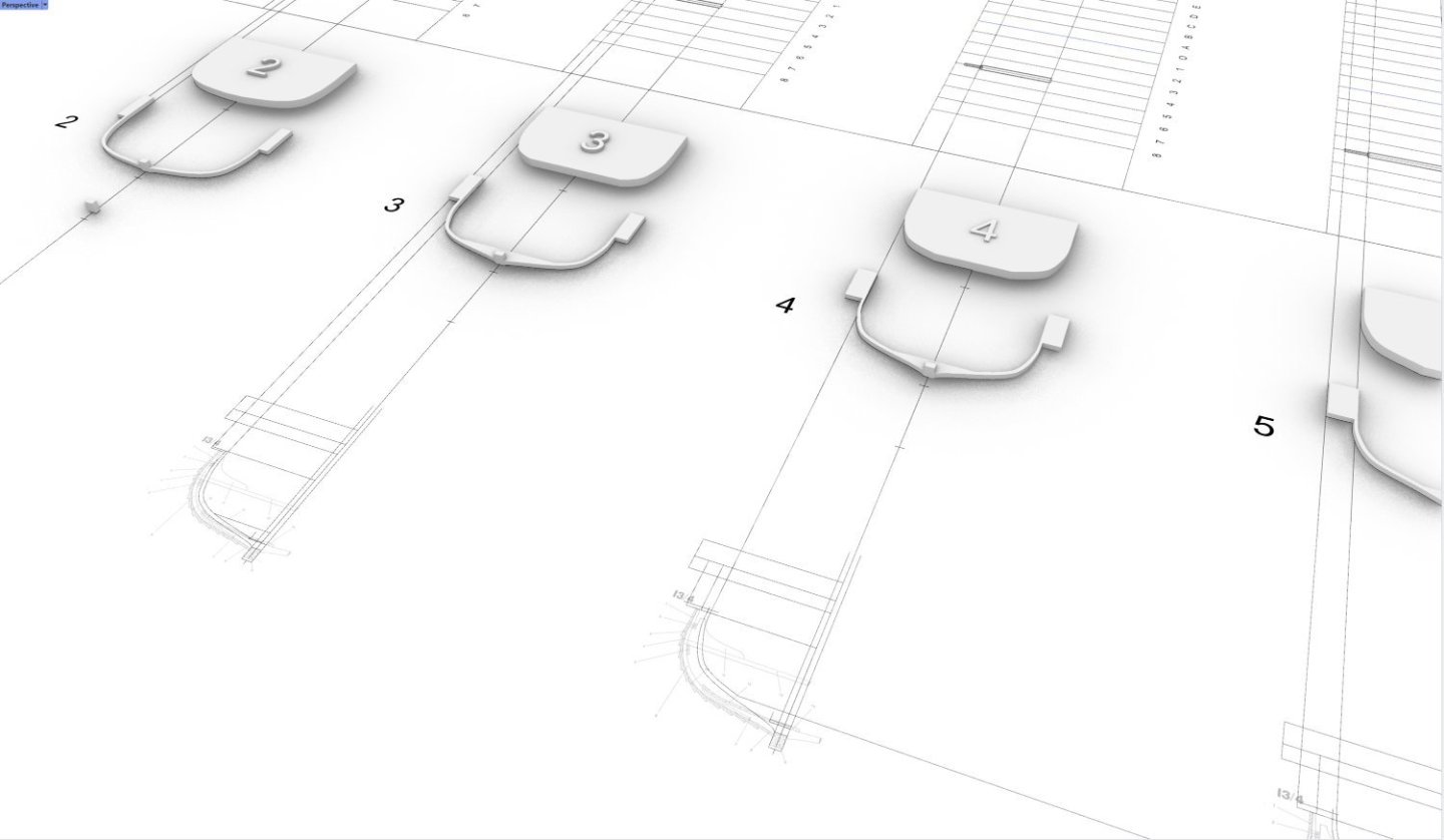
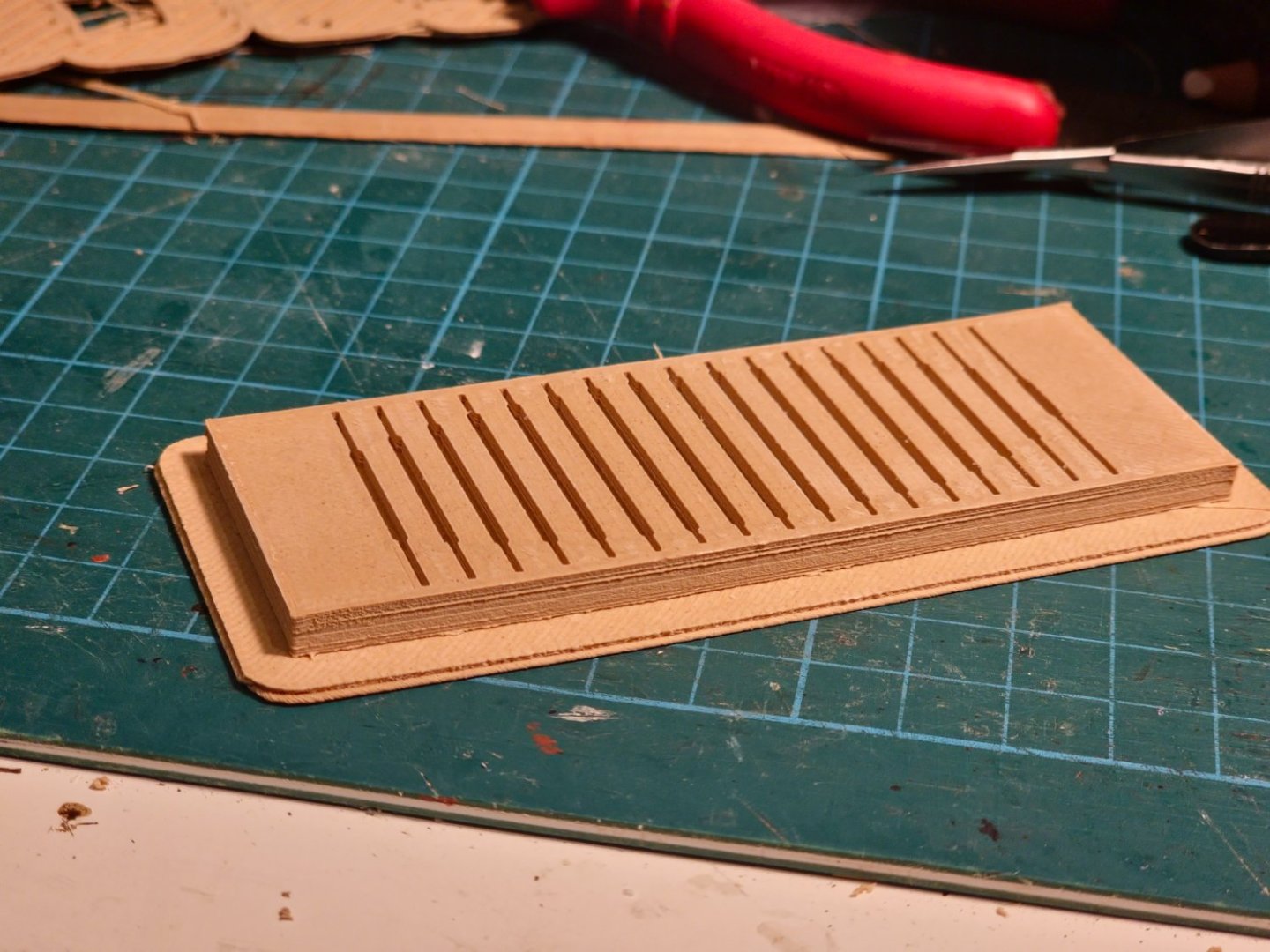
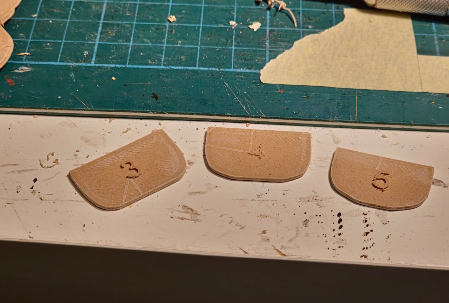
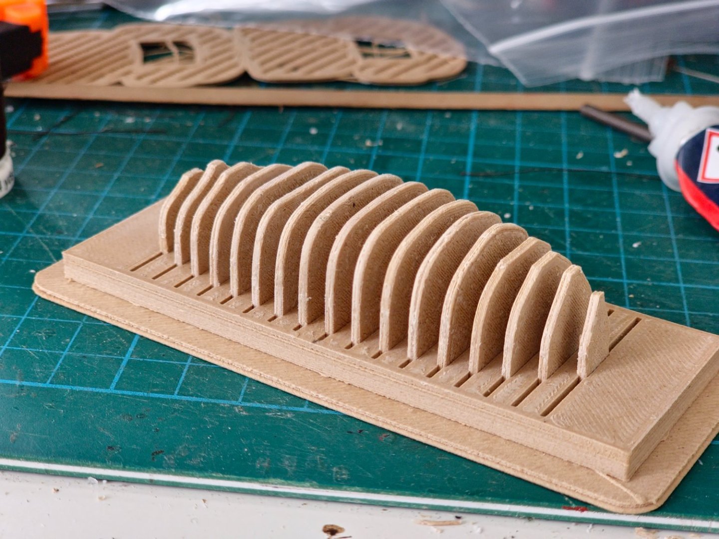
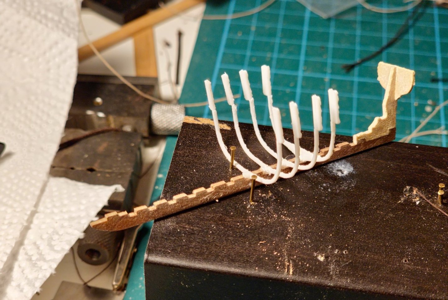
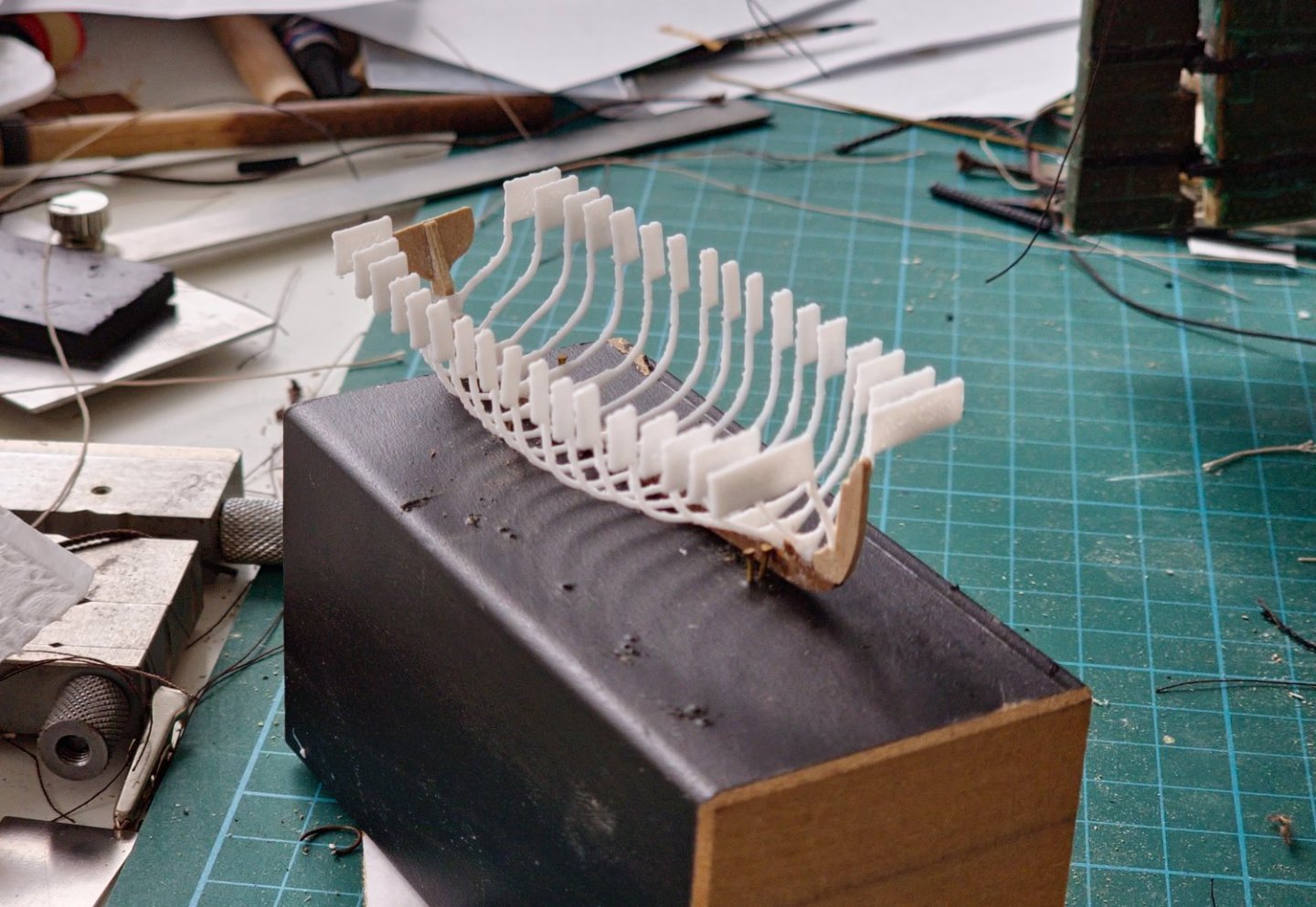
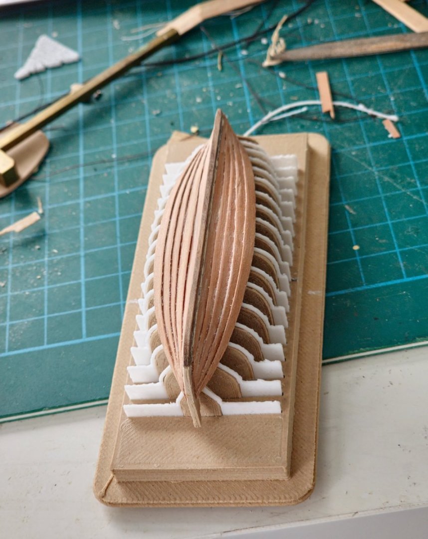
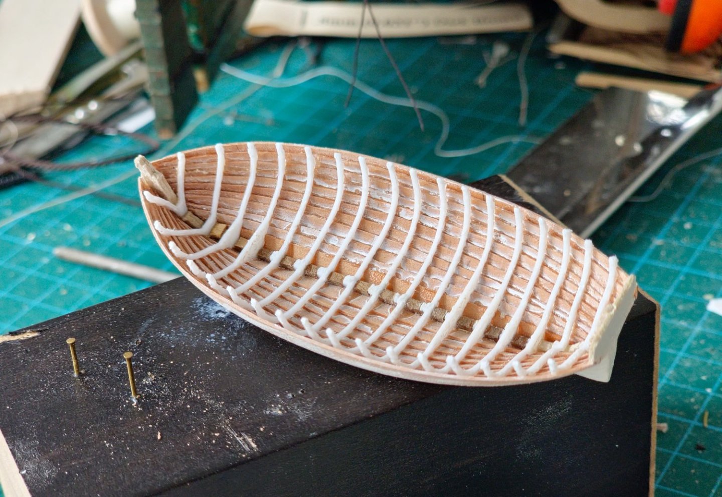
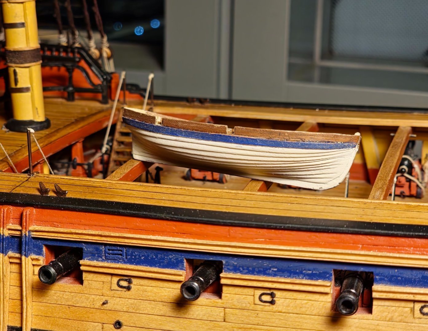
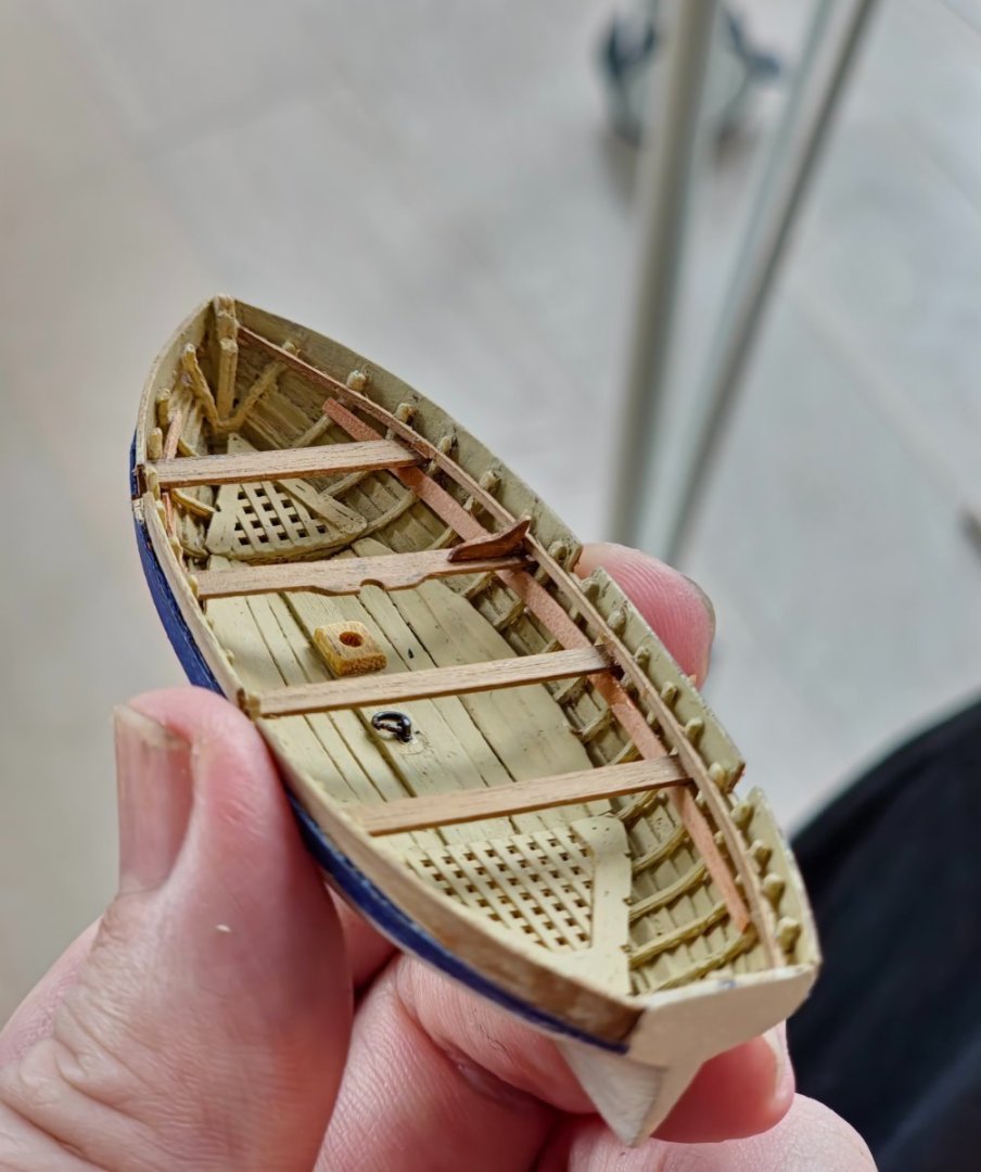
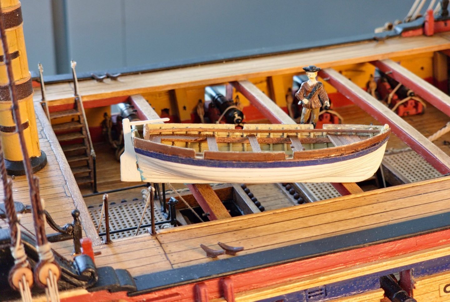
A bit of a hiatus between posts but I had some vacation time and after coming back I found it hard to overcome the inertia. The mizzen mast is much like the fore and main but with some subtle changes which means I will have to be on my toes lest I miss them. The sling is the same configuration but the diameter of the rope is only 0.5mm. The jeer blocks are lashed to the head in a different manner and must be installed after the shrouds are in place so that they sit snugly on top of the shroud pile. The first bit of rigging encountered are the burton pendants and these are a pair of singles rather than twin doubles. The rope is 0.5mm served dark brown. Luckily, I had used the 0.5mm diameter rope while bungling the fore pendants. These were replaced using a larger diameter rope that allowed me to recycle and repurpose these first attempts for the mizzen. Once I had fixed the top with strong epoxy, I noticed that it had a bit of a slant to port. I somewhat optimistically thought that I could correct this by giving it a good twist but just succeeded in demolishing the crosstrees and the whole assembly came tumbling down. I managed to salvage the pieces and then added a shim to the top of the port bib to straighten things out. I had to rebuild the top insitu but, with lashings of CA and structural paint, it mostly went back together again. Shrouds were added in the traditional manner although they were 0.8mm diameter with 3mm diameter deadeyes. Steel calls for the lanyards to be 0.32mm so I used 0.35mm rope which was the closest I had. I struggled to get the deadeyes to line up and I had to cut out some lashings and retie on multiple occasions. Still not perfect but good enough. Ratlines were slightly less onerous seeing as there are only two pairs of shrouds and a swifter to attach to which is a great saving in clove hitches but the same amount of cow hitches which I find are not as fun as a clove hitch. I had to order some more rope from Ropes of Scale as I had not initially planned on using the 0.25mm diameter for my ratlines and the fore and main masts chewed through my existing stock. I thought that I had enough for the mizzen but ran out half way down so there were more delays as I waited for Canada Post to bring reinforcements. The rope duly arrived which allowed me to finish the lower mizzen ratlines. Futtock staves, futtock shrouds and catharpins were all similar to the other masts albeit in smaller diameters and fewer numbers. Futtock shrouds are 0.5mm diameter. I used 0.85mm diameter black annealed wire for the futtock staves compared to the 1.0mm I used for the fore and main masts. While I was waiting for the rope to complete the lower mizzen rigging, I started to repaint the window frames at the quarter galleries. I had originally painted these white but it was a bright titanium white that was not in keeping with the overall look of the ship. I am going over these with a white that has been coloured with a splash of yellow ochre. I have just started this task and it already looks a lot better but painting these in situ is not the easiest. It is further complicated by my not being able to turn the ship upside down now that I have the masts in place. I am still not happy with the faux caryatids but I am at a bit of a loss as to how to improve these. I will extend the base down to the lower moulding though as that seems achievable and will make them look more grounded at least. To break the tedium of window frame painting I thought I would have another stab at a ship's boat. I had covered the trials and tribulations of my first efforts in an earlier post but I was not happy with how they turned out. I was looking for futtocks that were closer to the actual dimensions used but had to go with larger sections due to structural concerns and the limitations of my current 3D printing setup. I was reading a book about whaleboat construction and they had a photograph of the futtocks being shaped over formwork. I figured I could use a similar arrangement for the small boat construction. If I introduced a form at each futtock location that would give the thinner member enough support while I finished the planking. Once the planking was in place it would theoretically have enough structural integrity to hold its shape. The poor quality of the printed members would have to be lived with unless I invested in a new resin printer. I could possibly disguise some of the shortcomings with lashings of paint. I got CADDing and knocked out the parts for the jolly boat as this is the smallest boat which would theoretically be the most challenging. I made a base that would accept the formwork pieces. I added a number/letter to each of these so that I would not get confused and insert them in the wrong slots. The printed futtocks are incredibly delicate and I dare not give them a hard stare less they wilt. These were then inserted into slots milled into a 1.5mm thick walnut keel. Once they are draped over the temporary formwork though they are quite robust and can stand up to some vigorous planking. The ears that secure them to the base will be cut off once planked to allow the hull to be lifted free from the formwork. I think that it is a viable construction technique for those that are better hull plankers than I. As this is a 18ft cutter (jolly boat) I had to approximate the clinker construction. For accuracy the actual planks would scale to around 0.3mm x 2.2mm in section. I used some pear I had lying around although this is slightly thicker at 0.4mm and I cut the planks around 2.5mm wide. Close enough for my clumsy tolerances, however, using these tiny planks did not go as smoothly as it did in my mind. After the first few planks there was noticeable asymmetry and for me it was not practical to go down the tick mark and spiled plank route given the tiny size and my short attention span, so I resorted to eyeballing things which resulted in a bit of a mess. I ended up with one more strake on the starboard side compared to the port much to my embarrassment. Once I cut it from the formwork, I noticed that the planking had fought against the tight radius of the hull and was pulled away from the top of the futtocks. I attempted to mitigate this by introducing a thicker wash strake but it was not a complete success and would still require some distortion to be applied to the head of the futtocks to close the gap. As it us a prototype I applied a rough paint job and fitted the inside with gratings and footwalling salvaged from a previous prototype just to see how it looked. I added the thwarts and various other bits and bobs to see how the rest of the details worked and to test out some colour combinations. I did not bother finishing it and some of the elements are held in place with blu-tack. I suppose it is not the jolliest of boats but it is quite cute. I have lost count but I think this is Jolly Boat prototype number five. I have noticed that each of these prototypes has been an improvement on the previous version so given an infinite amount of time and patience I would theoretically eventually end up with an acceptable product. I think that going forward I will either have to bite the bullet and get a new printer or just order one of the Vanguard mini kits. The 1:64 scale is not my friend in this endeavour. A lot of running in place but some progress nonetheless. I do not know if I should continue with the masts or mix it up with some yard construction or perhaps even have another stab at another ship's boat prototype. Given how long it has taken me to progress the first ship's boat I think that I will limit the complement to three boats down from the five mooted in May. I am thinking the jolly boat, the 26 ft yawl and the 32 ft pinnace. That would give me a one of each type and I could mount two on the skid beams and have one hoisted in the rigging as if being launched. That way I will not totally obscure all the detail of the upper deck with shabby looking boats but I reserve my right to change my mind at the last minute.


-
Congratulations on finishing your excellent build David. The additional details that you have introduced really lift the model to the next level. Regards, David
- 310 replies
-
- 1
-
-
- Diana
- Caldercraft
- (and 1 more)
-
Thanks for the kind words JJ, Dave and Allan but it is early days yet and you should not underestimate my ability to spectacularly botch it from here on in. Regards, David
-
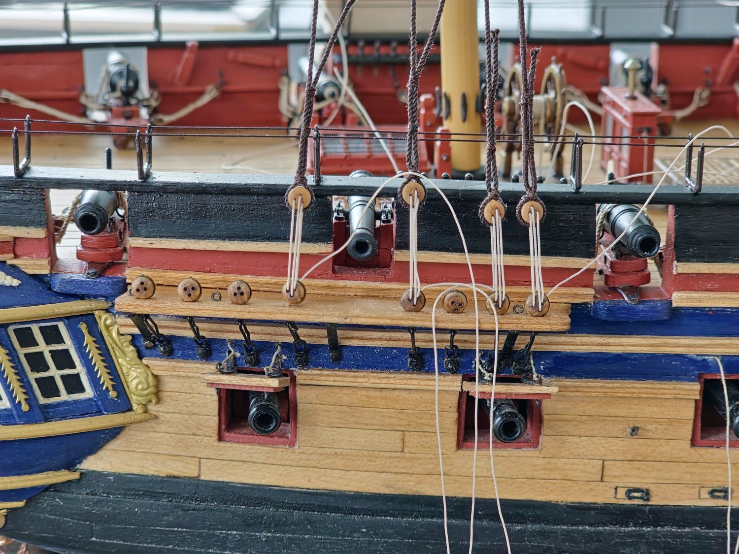
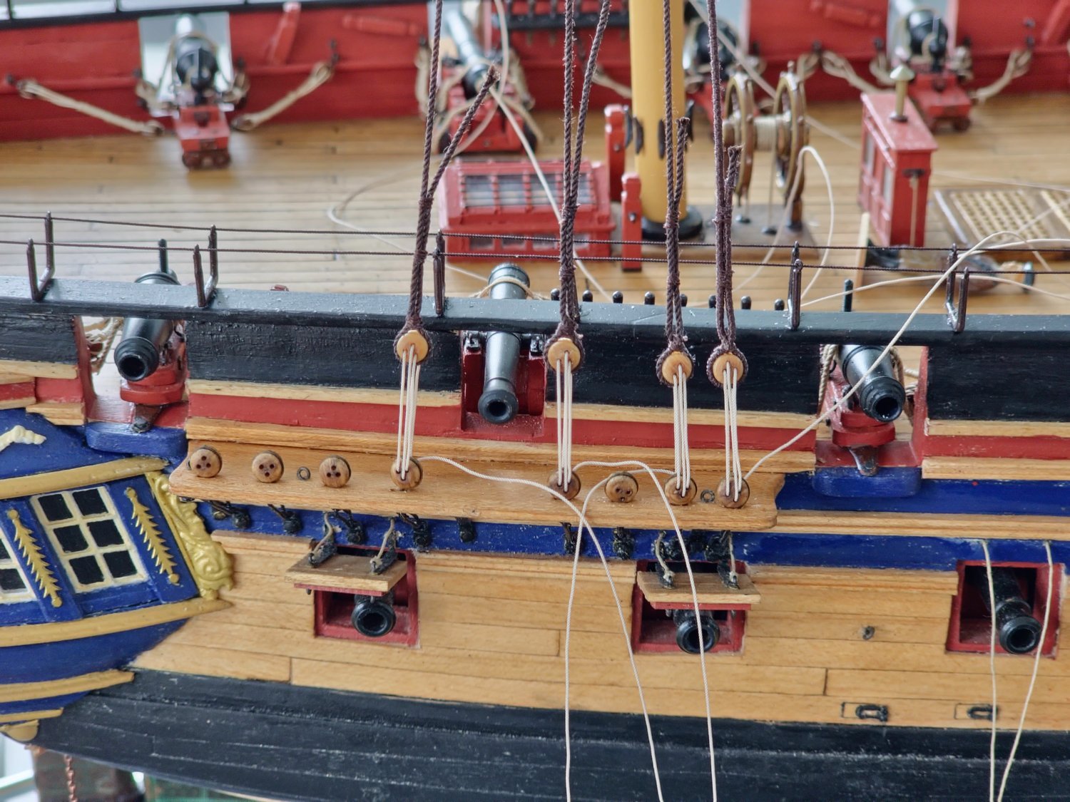
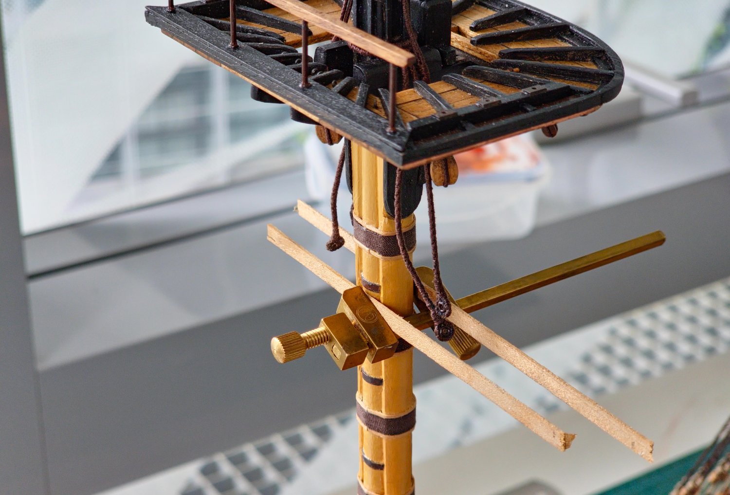
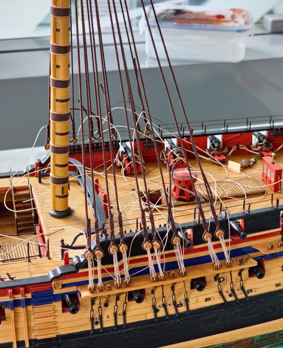
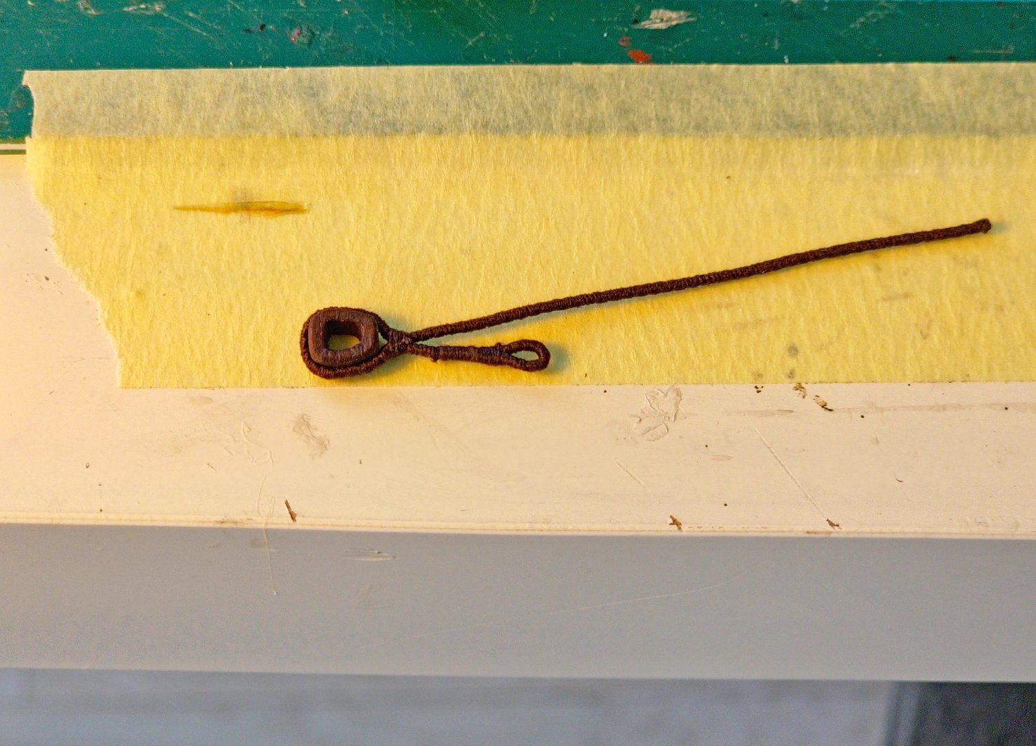
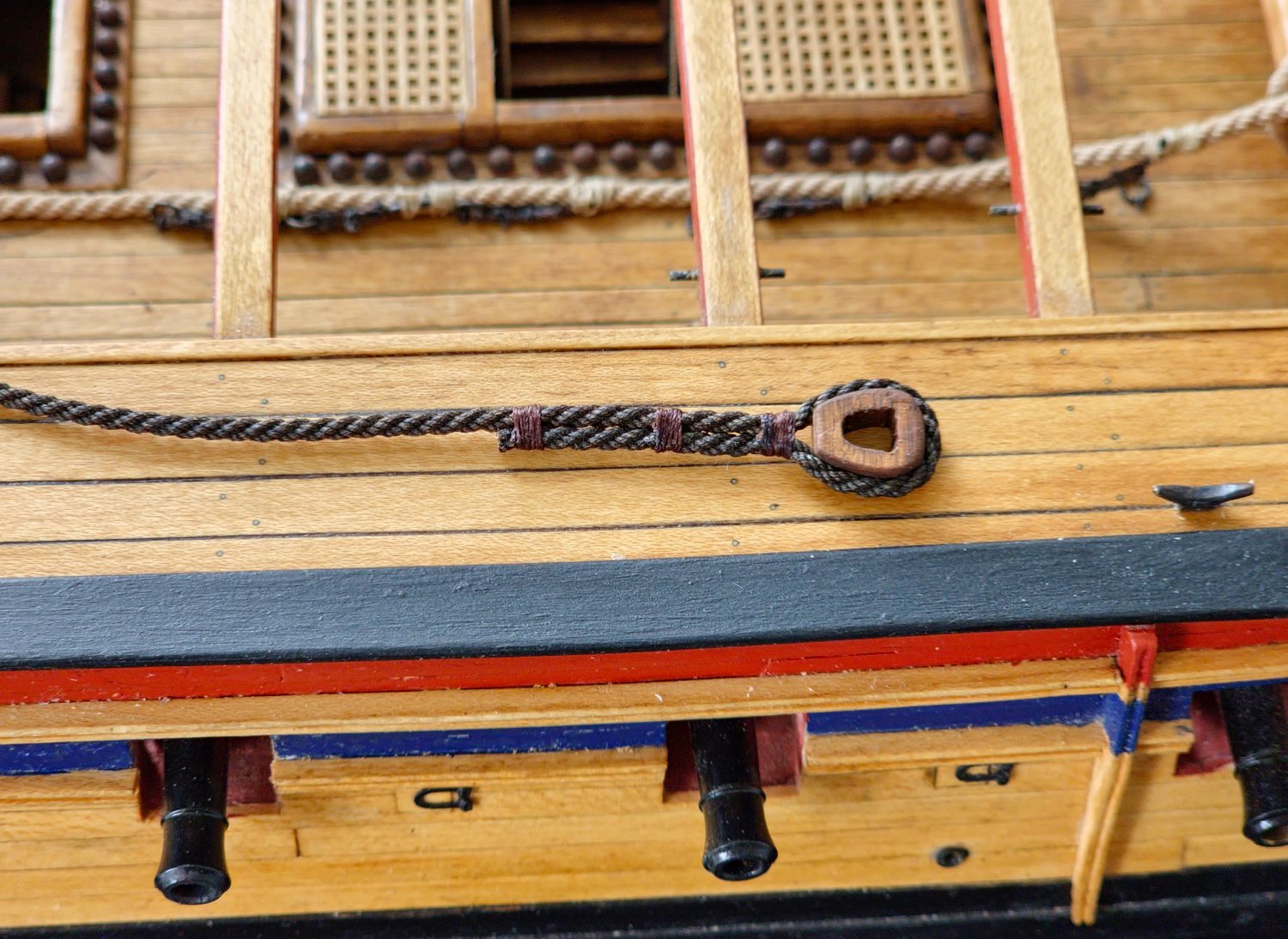
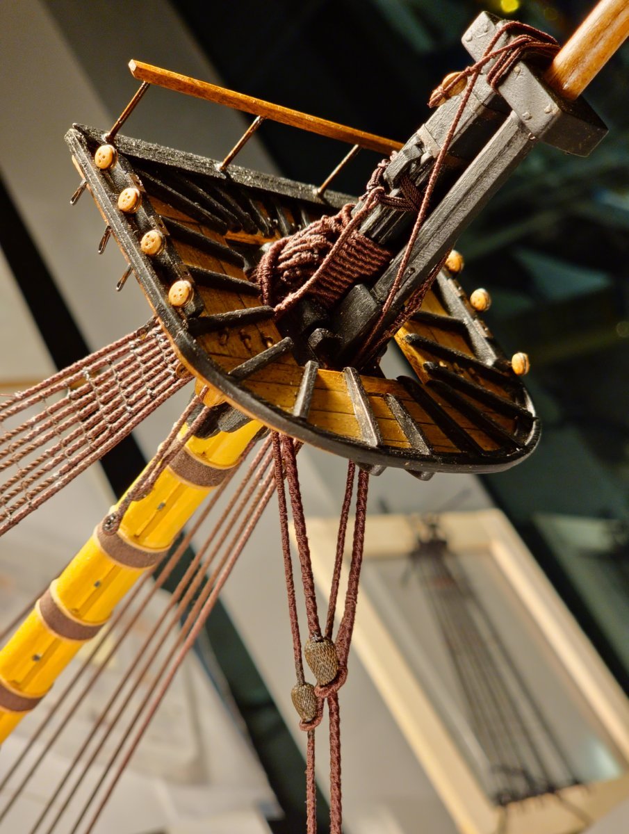
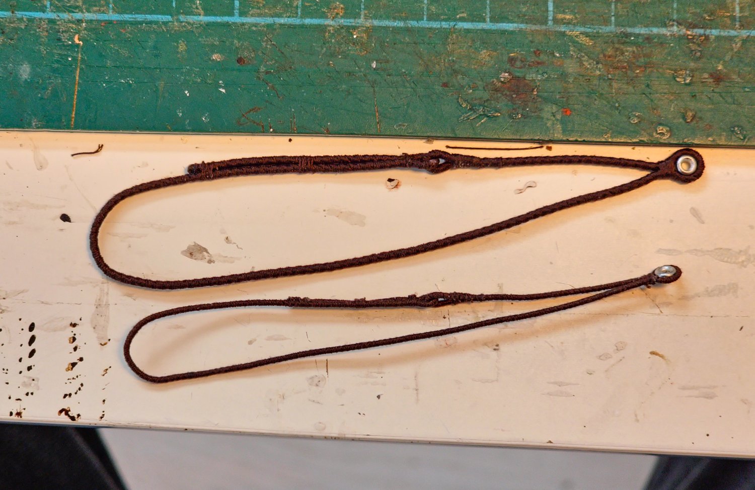
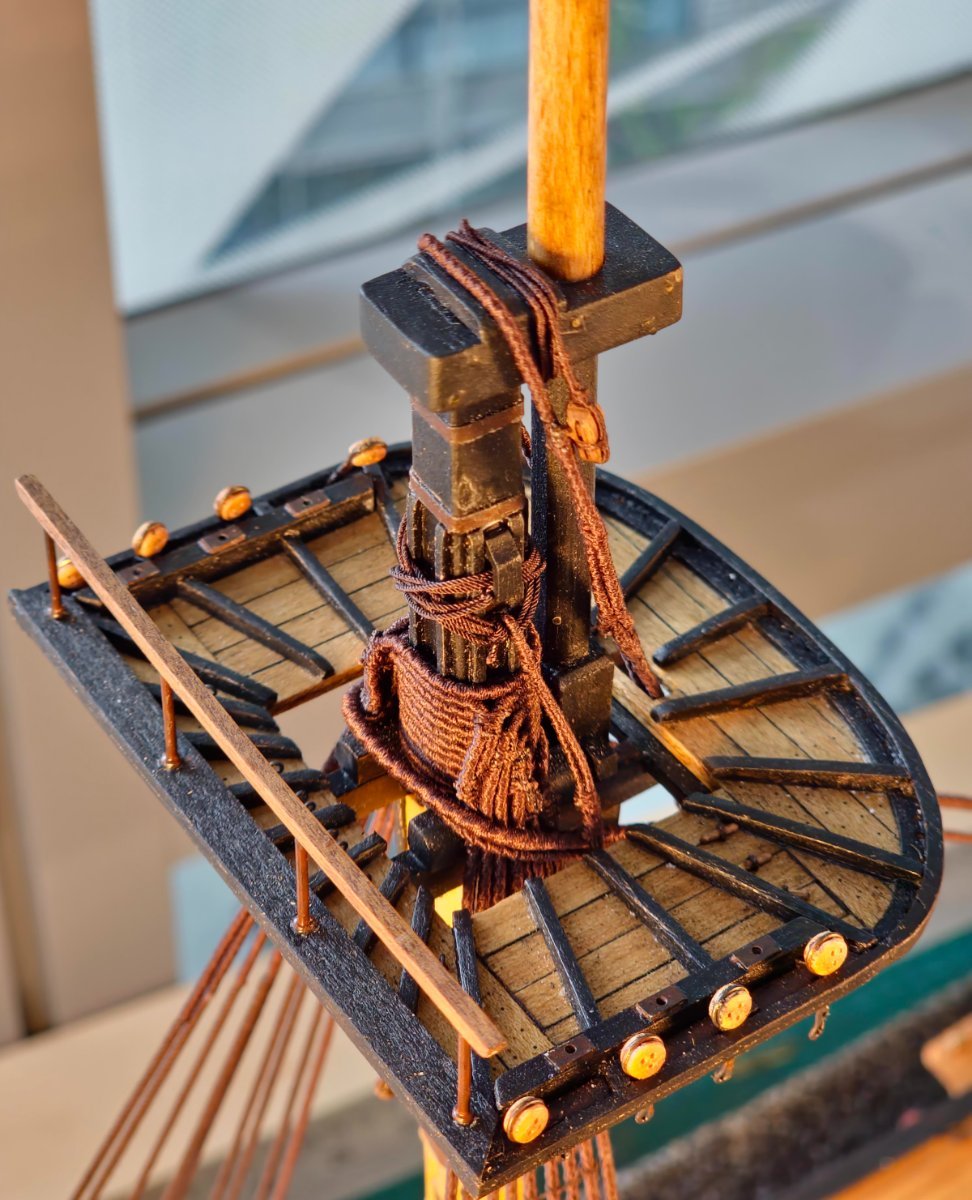
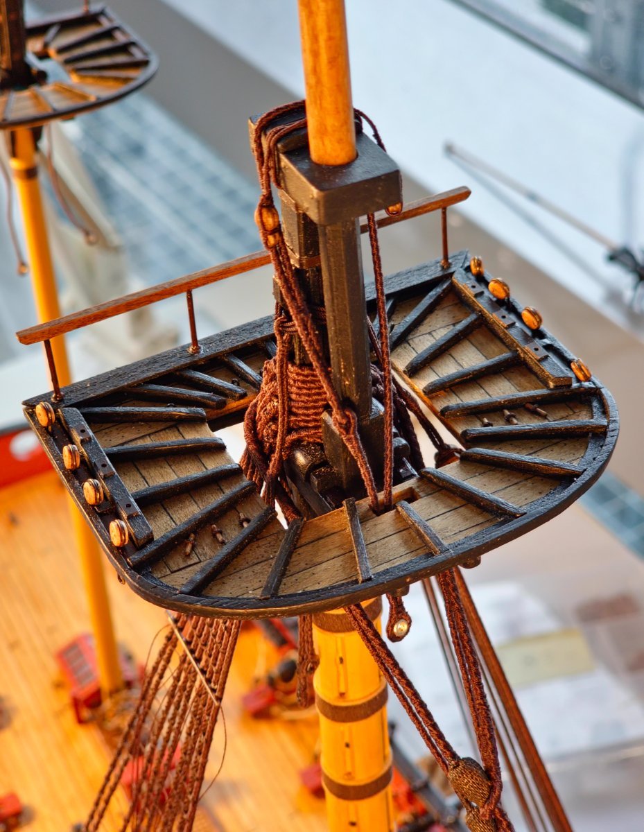
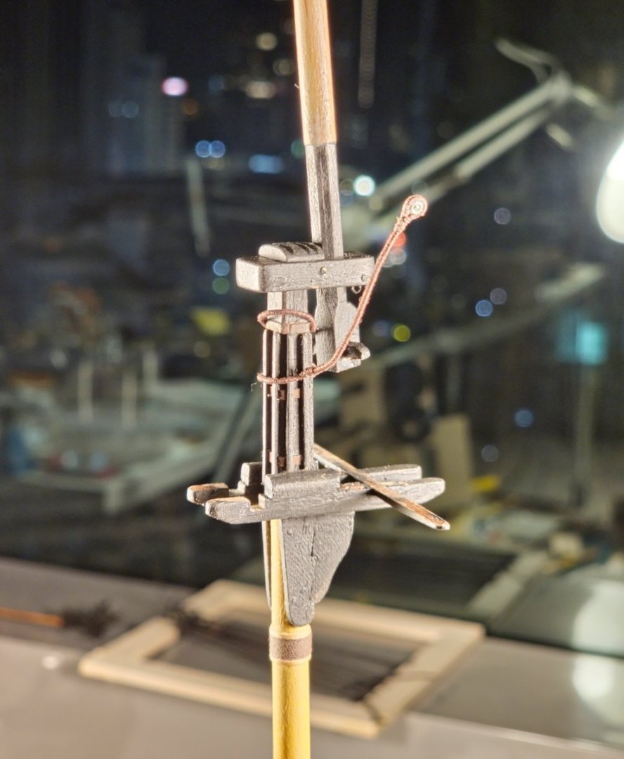
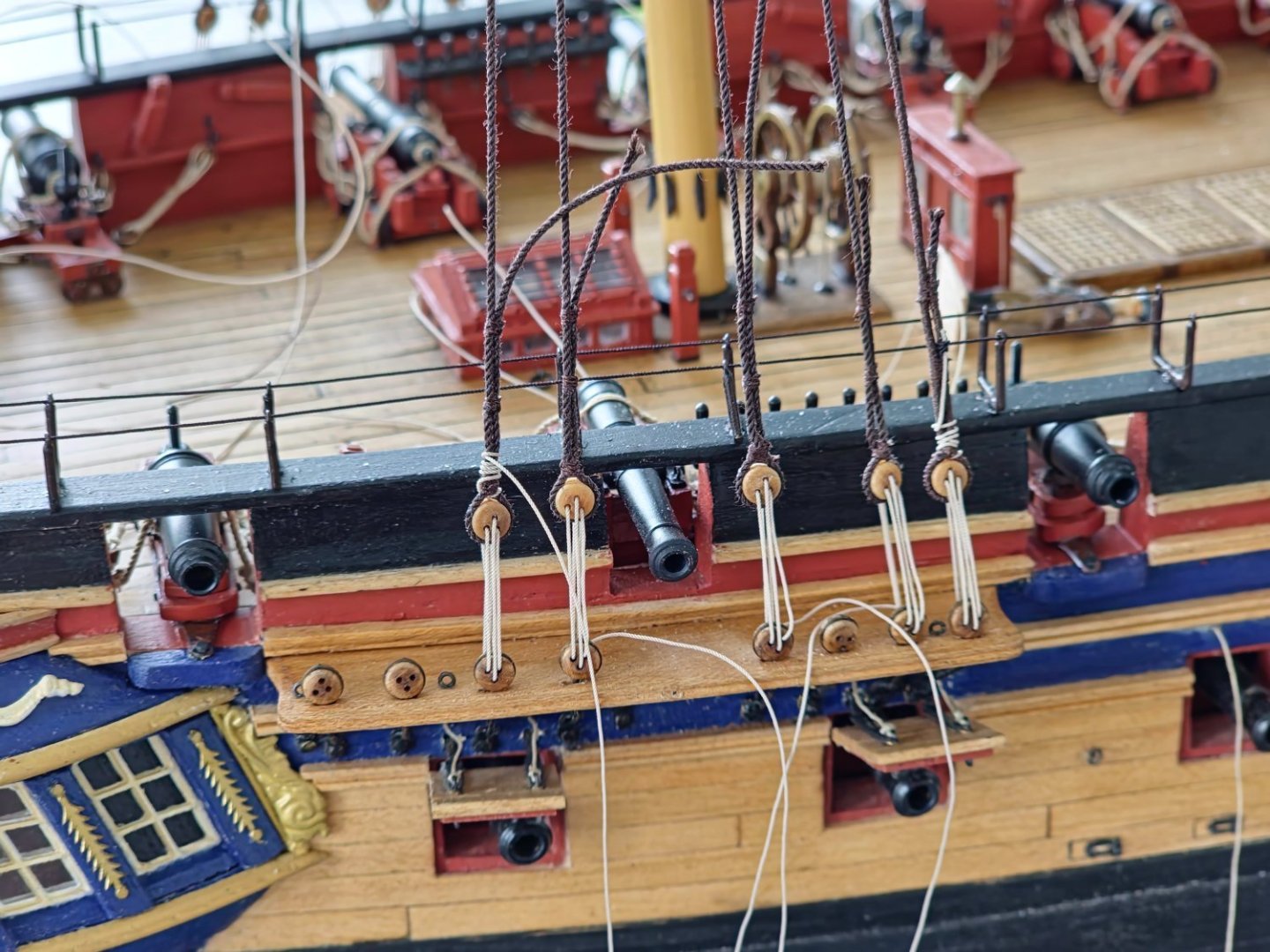
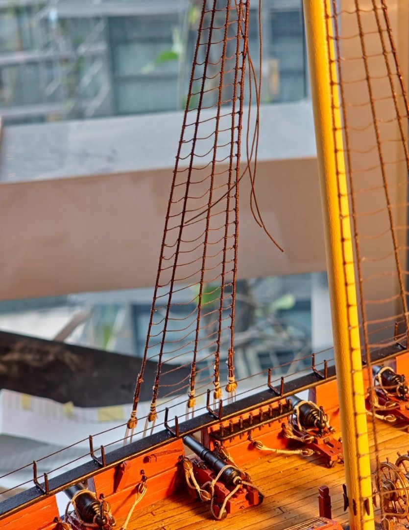
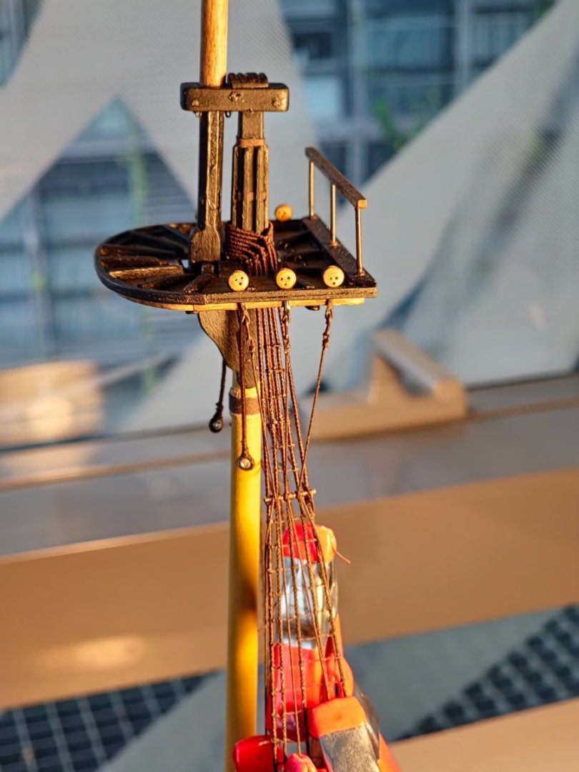
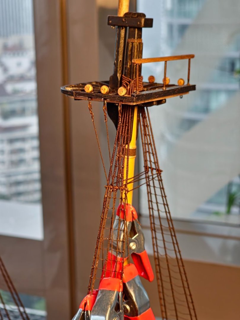
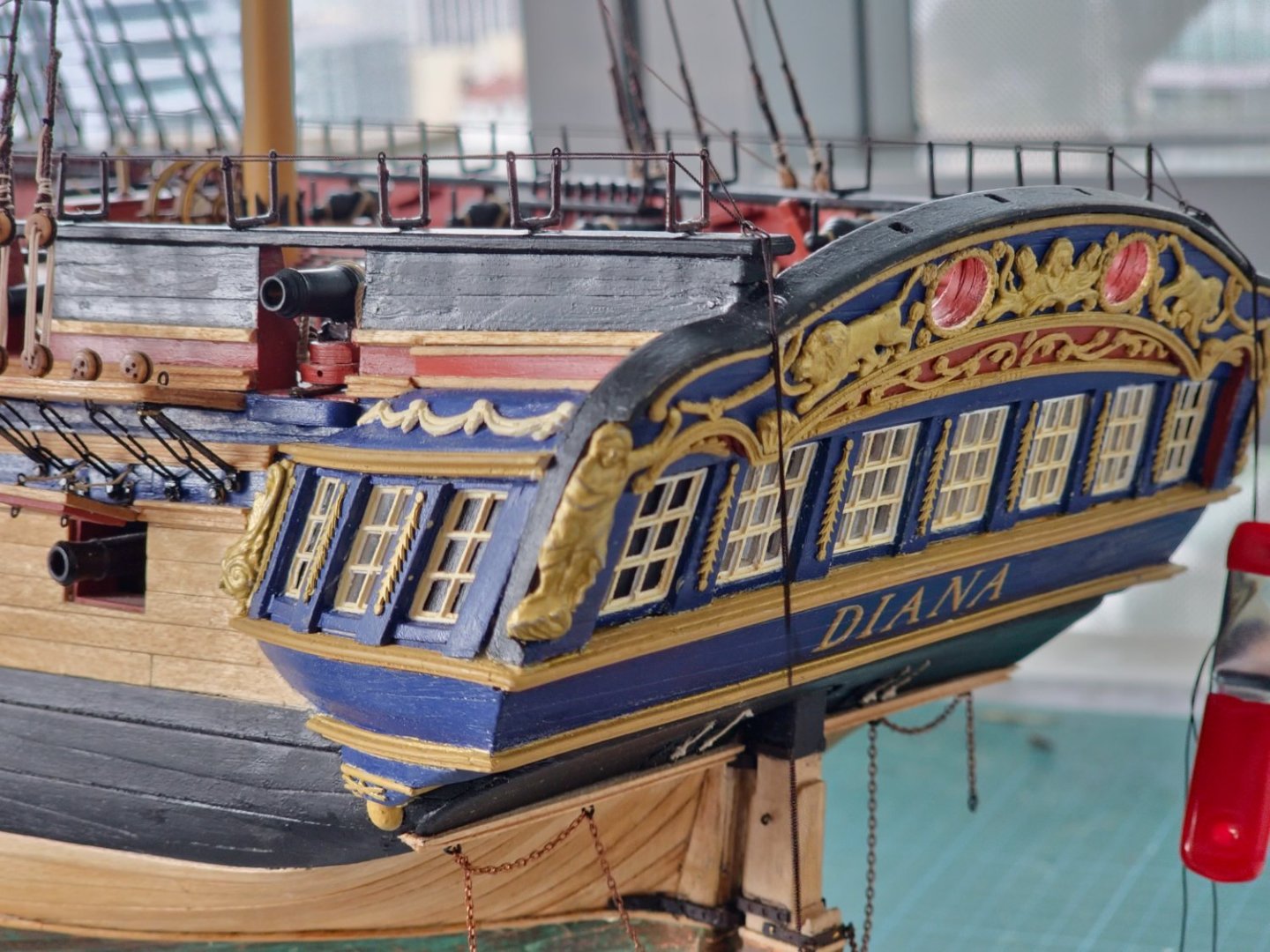
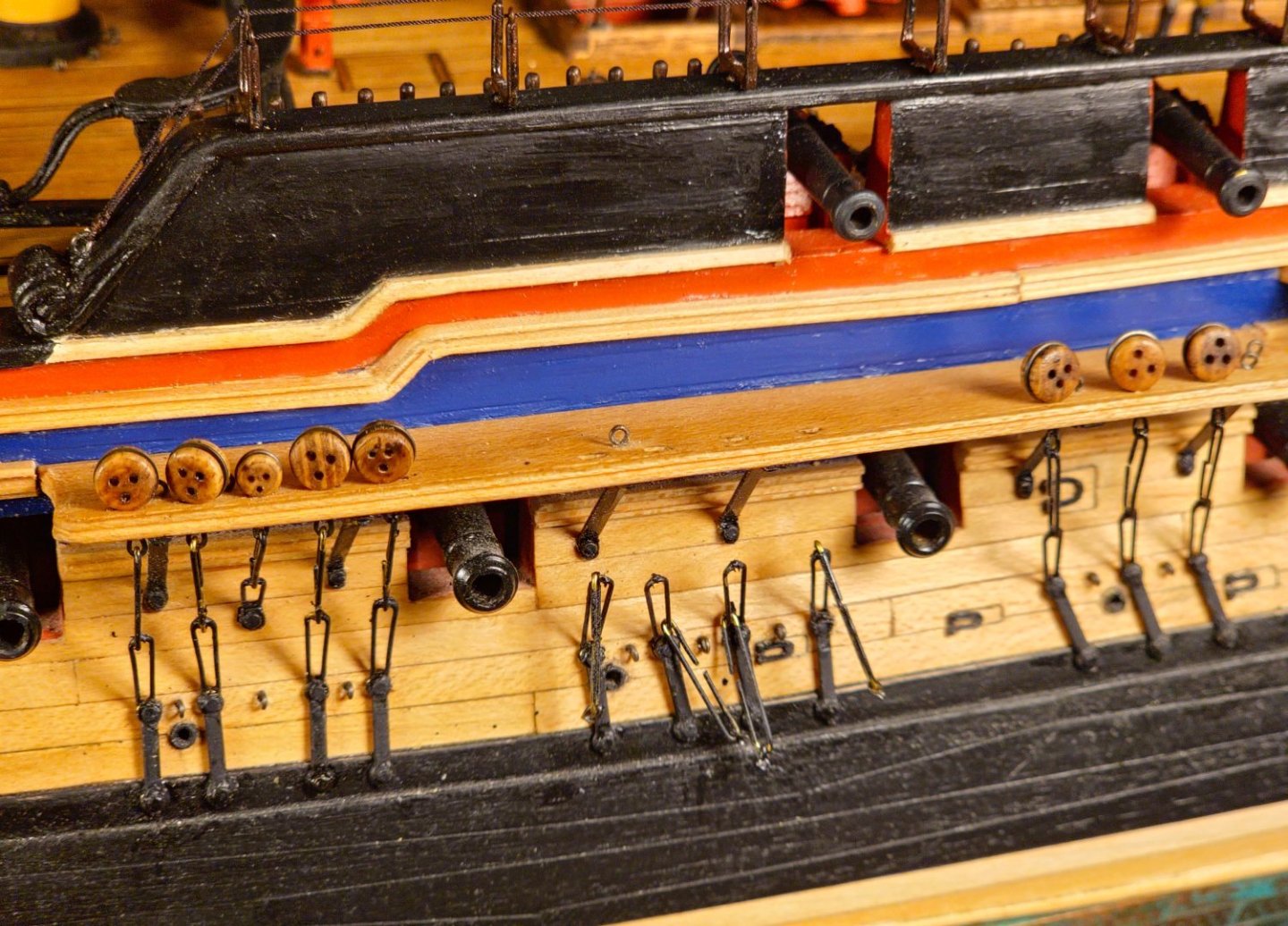
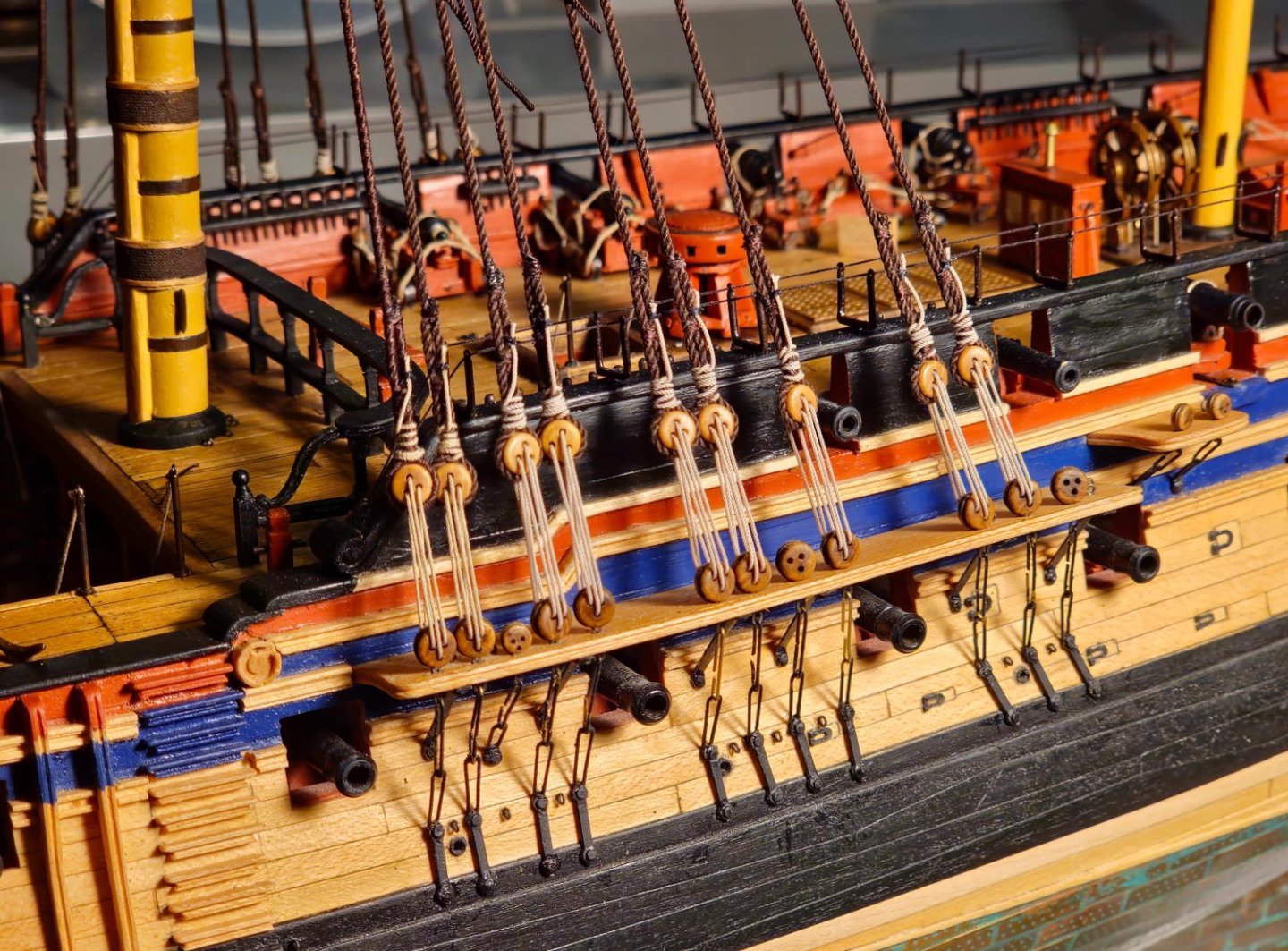
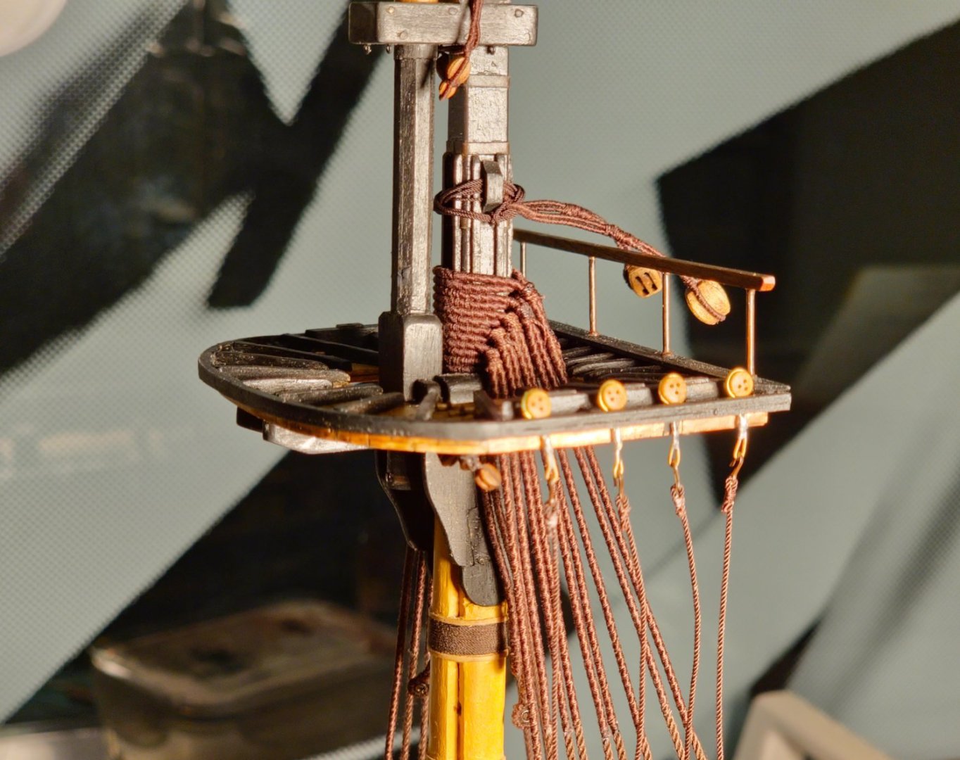
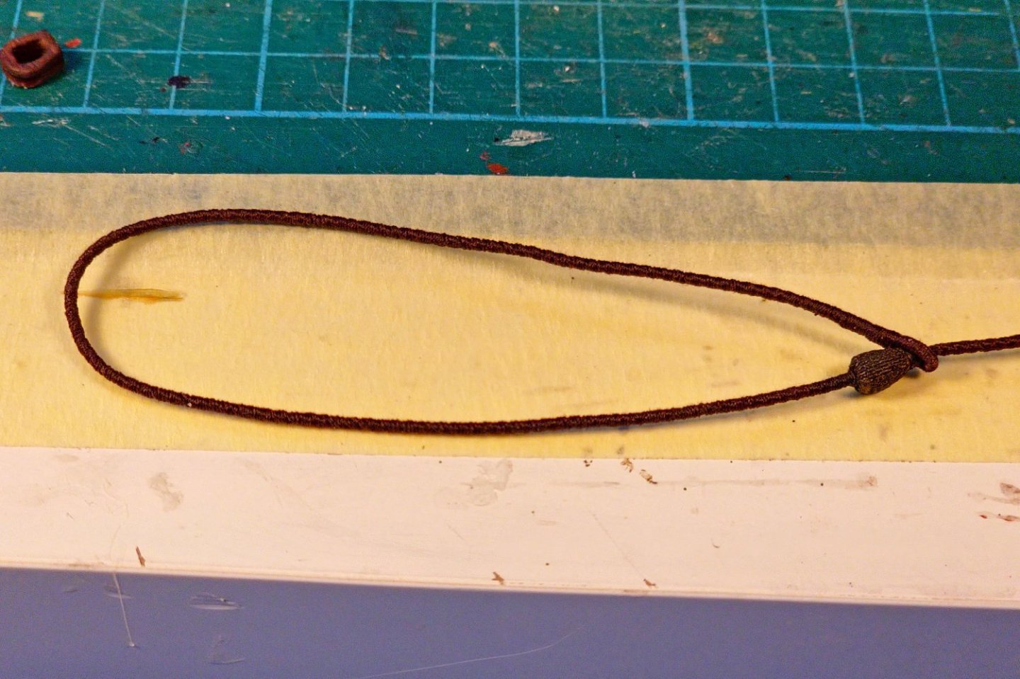
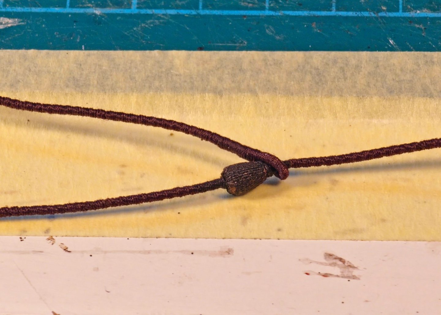
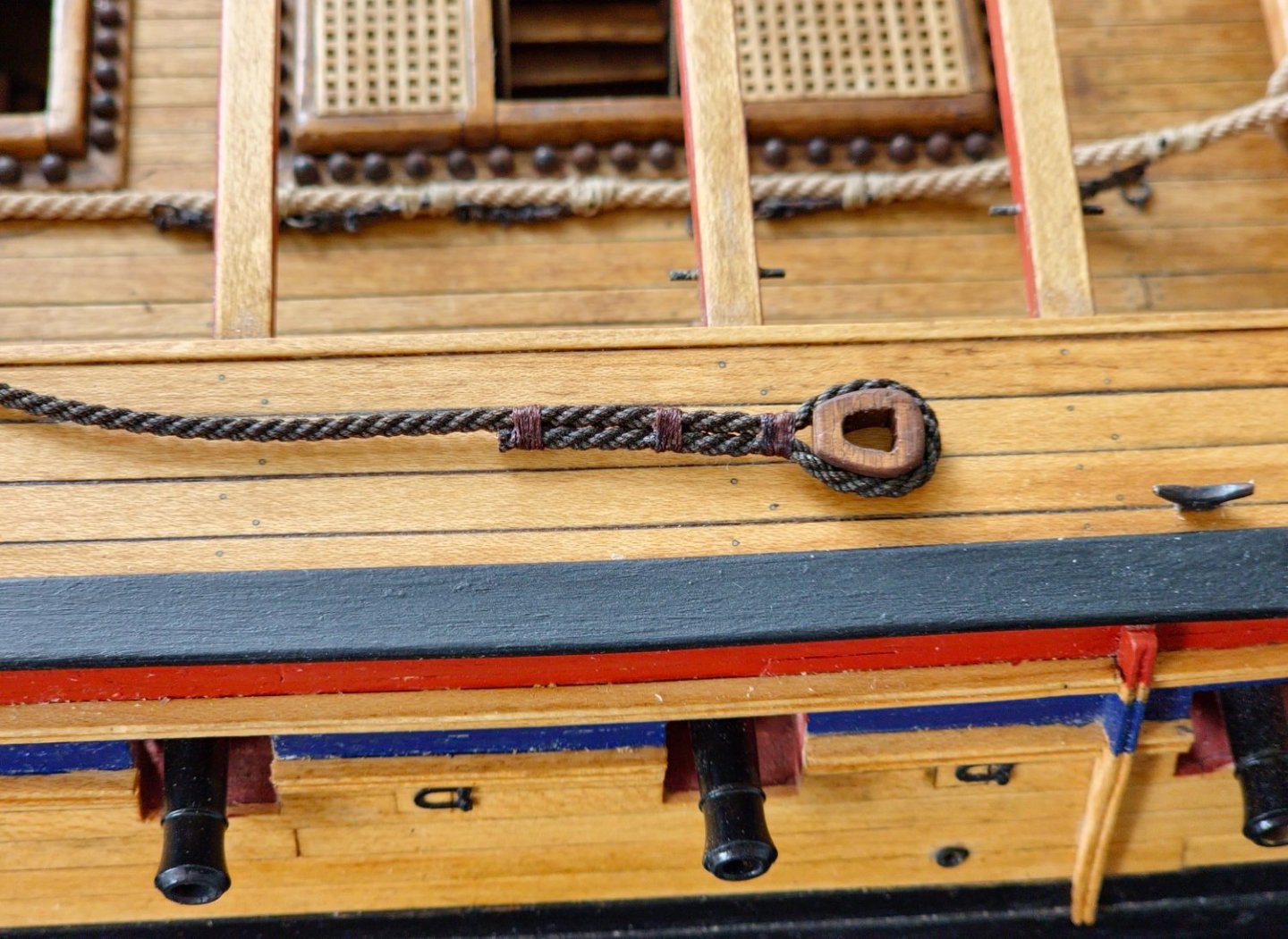
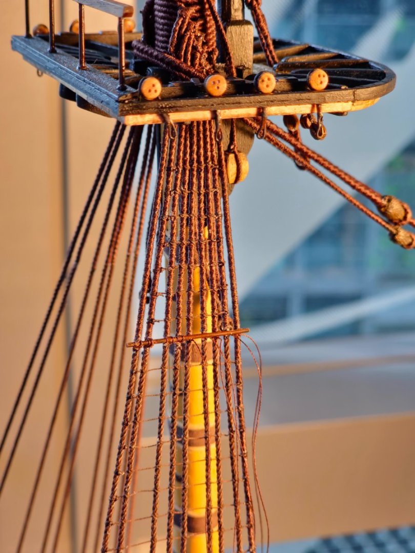
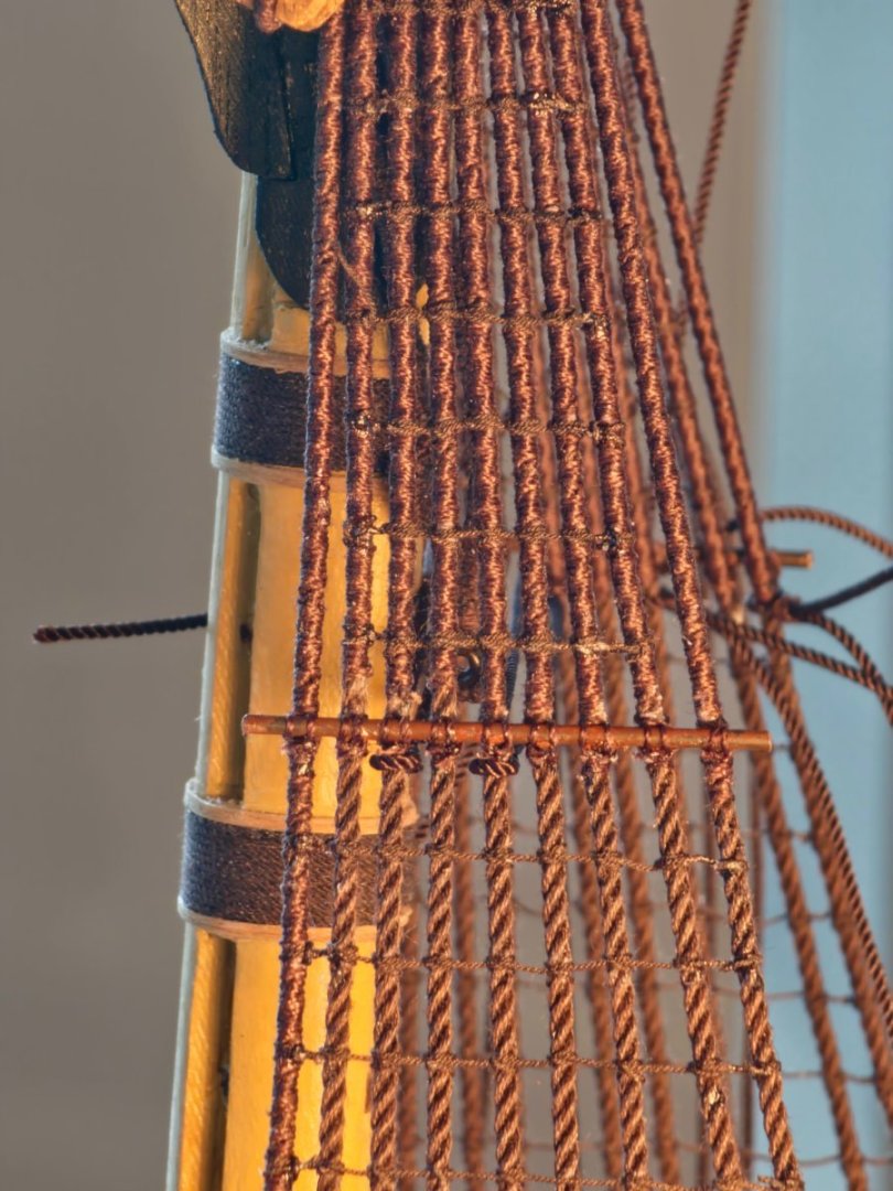
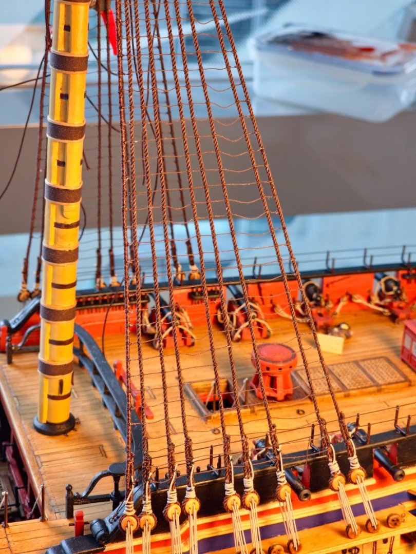
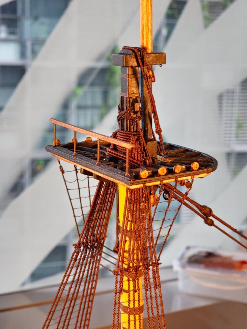
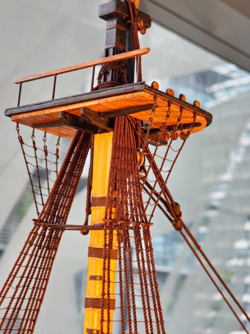
The installation of the quarterdeck hammock cranes allowed me to carry on with the main mast lower rigging. I had to switch out the deadeye strops from my homemade ones. I bought some new deadeye strops from HiS models. These are PE and blackened which saves me a step or two over the Amati ones. The shrouds themselves are pretty much the same as the fore mast. They are 1.2mm diameter RoS dark brown rope which is closest to the 1.14mm diameter noted in Steel. They are rigged in the same fashion in pairs fore to aft alternating between starboard and port. The first leg is served all the way with the others only in the section around the mast until just below the futtock stave. It is a bit of a chore having already laboured on the fore mast but it would look funny if I left them off. The task is made all the more laborious as my homemade serving machine is beginning to wear out and the joints have become a bit loose. Seeing as I built it myself, I did not think about including a lifetime guarantee. I will have to do some maintenance or make some replacement parts I suppose. Once all the shrouds are in place it is back to the ratline tying. I mixed this up with the installation of the main stay and main preventer stay. The main preventer stay was 1.2mm dark brown rope but for the main stay Steel gives a diameter equivalent to 1.76mm at scale. I did not have anything of that size in the dark brown but I had some 1.8mm diameter beige cable-laid rope so I mixed up some ink to approximate the dark brown colour and dunked it in. Not a perfect match but it looks OK to my eye. I used the mouse I made previously, covered with the same woven sticking plaster, and painted with the same ink mixture I used for the rope. Serving was completed till about 29mm past the mouse and the other end was wrapped around the homemade heart block which was then lashed in place. When I returned to the model a couple of days later, I saw that the main stay had gone all floppy. I suspect that the process of soaking in the ink had caused the rope to shrink which then relaxed once tension was applied. I resorted to hanging some weights from the end and I will leave this arrangement in place for a while in the hope that it will eventually return to its original length and the long term creep will stop. While photographing the mouse, I decided the sling looked too puny. I rechecked Steel and discovered that I had bungled and it should have been made using a 1.14mm diameter rope rather than the 0.8mm that I ended up using so I remade both the fore and main mast slings with served 1.2mm diameter rope. As well as being historically accurate, the look of the robust version is more pleasing to my eye. The futtock stave, futtock shrouds and catharpins were all as per the fore mast. The futtock stave is 1.0mm diameter annealed black wire lashed to the shrouds using Gutterman thread in a simple 3 move lashing. Looks a bit of a mess in macro but my eyes are not that good in real life. I struggled a bit with the catharpins this time around and tied them too tight causing the shrouds to distort more than I liked. I eventually completed all the ratlines which turned out a bit more ragged than those on the foremast. I guess I should complete the lower shrouds for the mizzen mast before I start on the upper level of rigging. I still have some work to do before I can fix the mizzen top in place. It is a slightly different configuration to the other two masts so I will have to check the various sources to make sure that I do not forget to install an essential piece of rigging hardware or miss drilling a vital hole.


-
Thanks JJ I am still quite a beginner in the rigging department but I have found that upgrading the ropes helps draw the eye away from the clumsy knots. I just had a browse through your HMS Winchelsea build which looks fantastic. I really like the look of the admiralty board style but judging by the work on your cannons it will be a piece of cake for you to rig it beautifully. Regards, David