HOLIDAY DONATION DRIVE - SUPPORT MSW - DO YOUR PART TO KEEP THIS GREAT FORUM GOING! (Only 13 donations so far - C'mon guys!)
×


DavidEN
-
Posts
136 -
Joined
-
Last visited
Content Type
Profiles
Forums
Gallery
Events
Everything posted by DavidEN
-
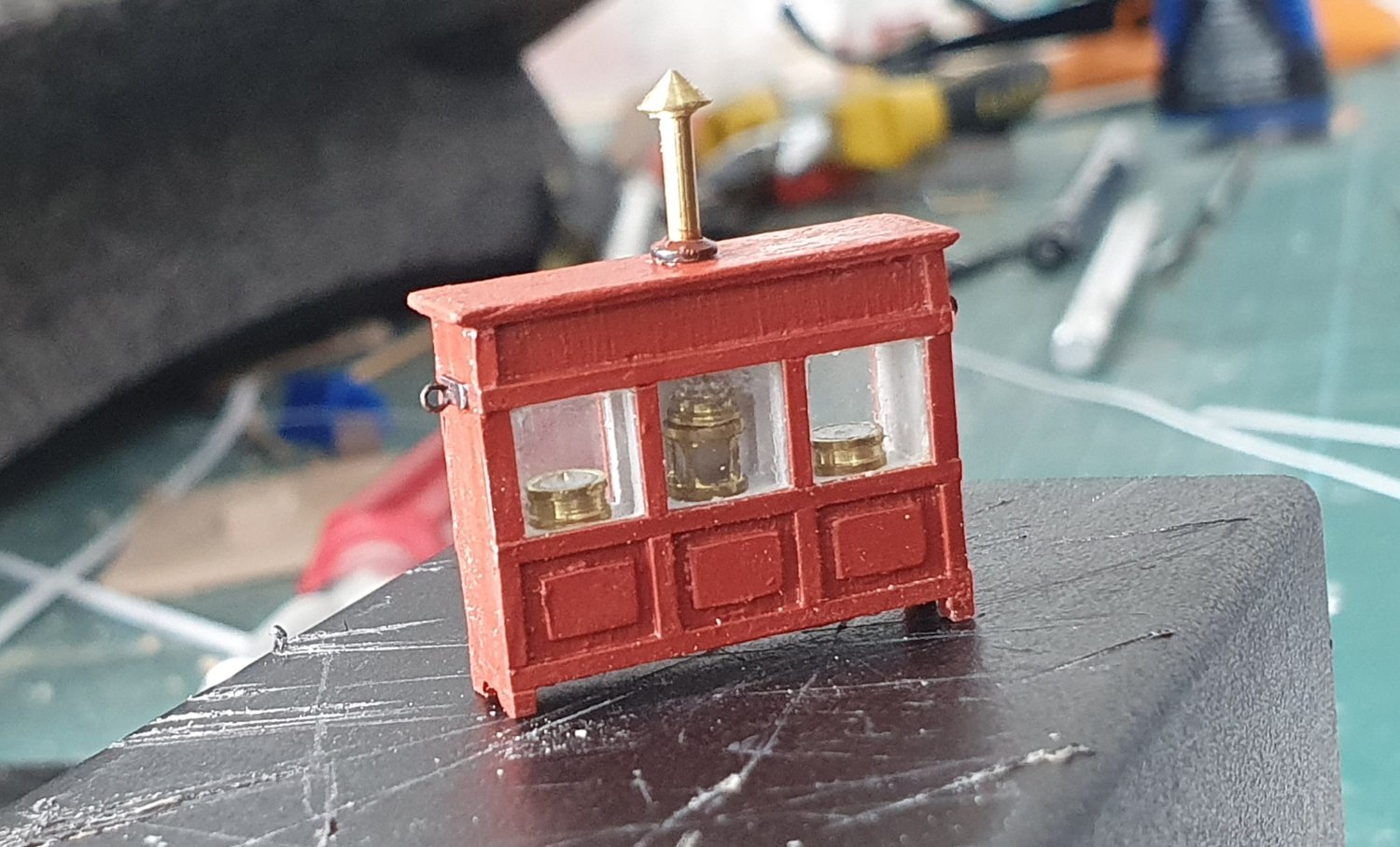
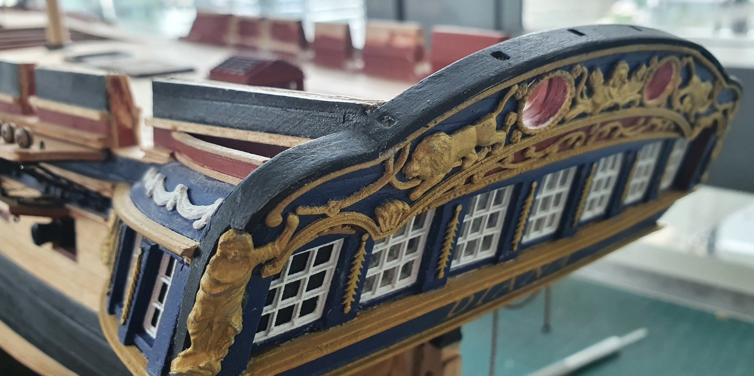
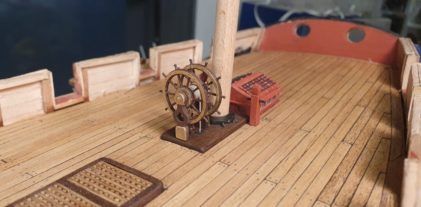
Thanks for the kind words Ab The William Rex is quite an impressive model. It has been a while since I was in the Rijksmuseum and I can't recall seeing it. Perhaps it was out for cleaning. I believe it is a 17th century Dutch ship so I think that binnacle may not be identical to an 18th century English example. As Rob pointed out above I did base it on the HMS Victory binnacle which is plusher but not dissimilar to the one aboard the Trincomalee a slightly later frigate of 1816. I found the amount of information about binnacle design through the years is quite sparse. A real opportunity for someone to step up and produce a scholarly book about the subject. Apologies if somebody already has and I have missed it. Regards, David
-
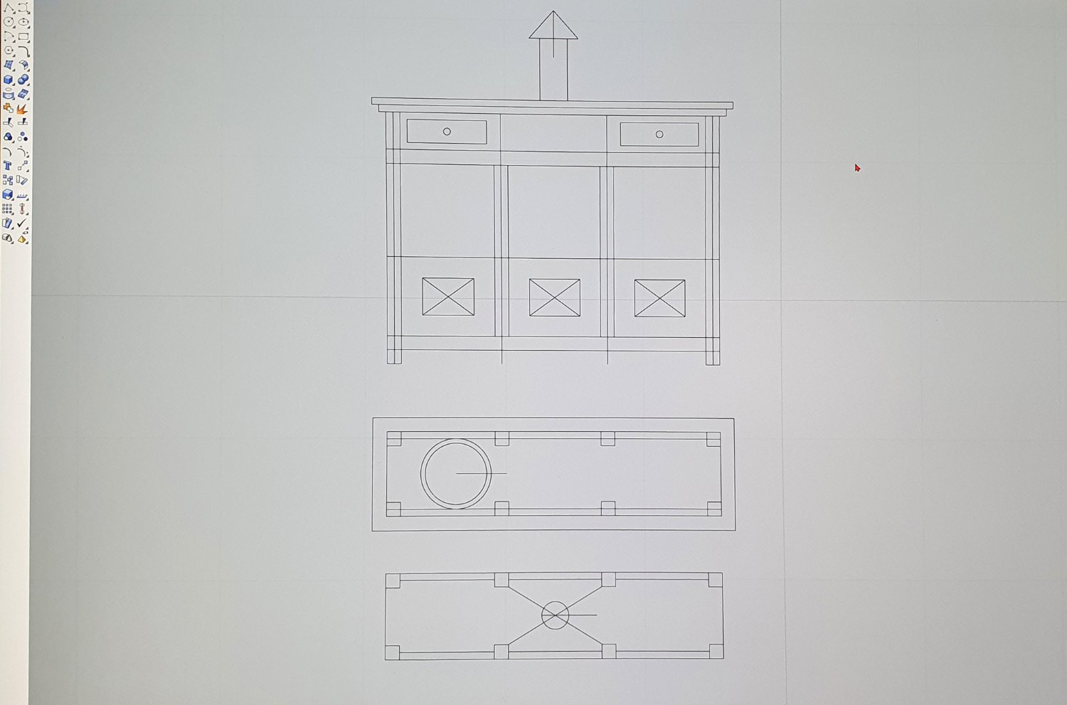
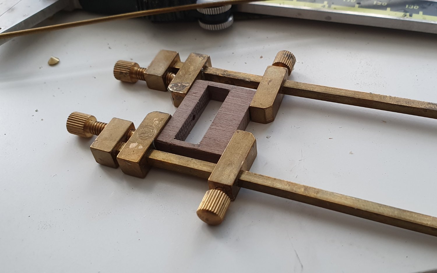
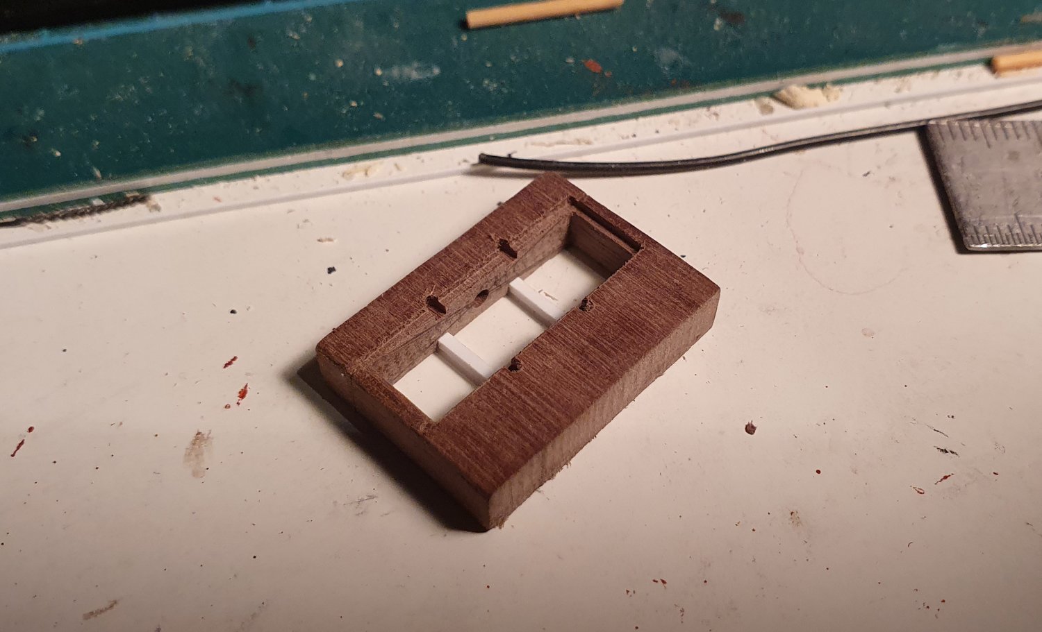
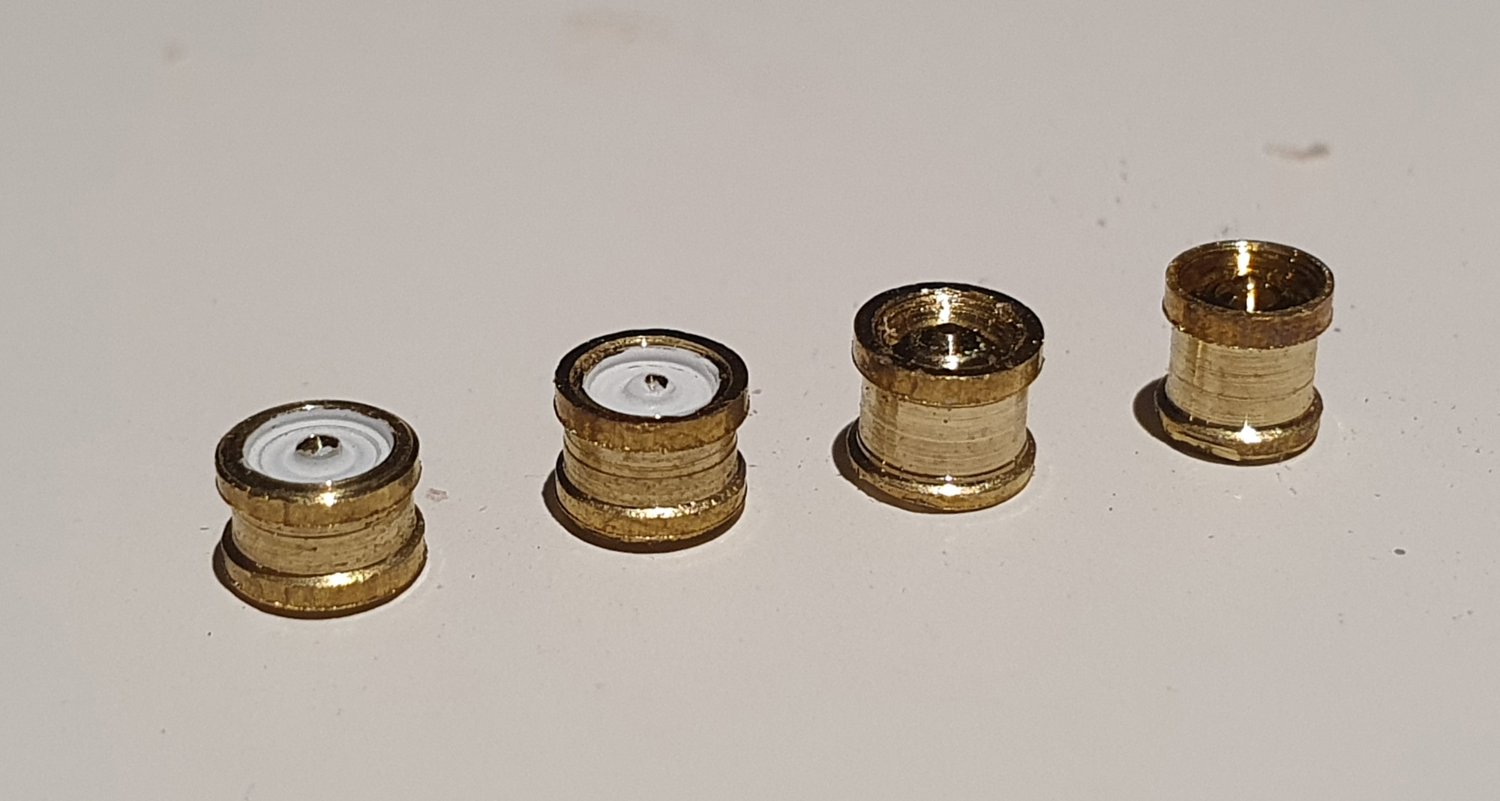
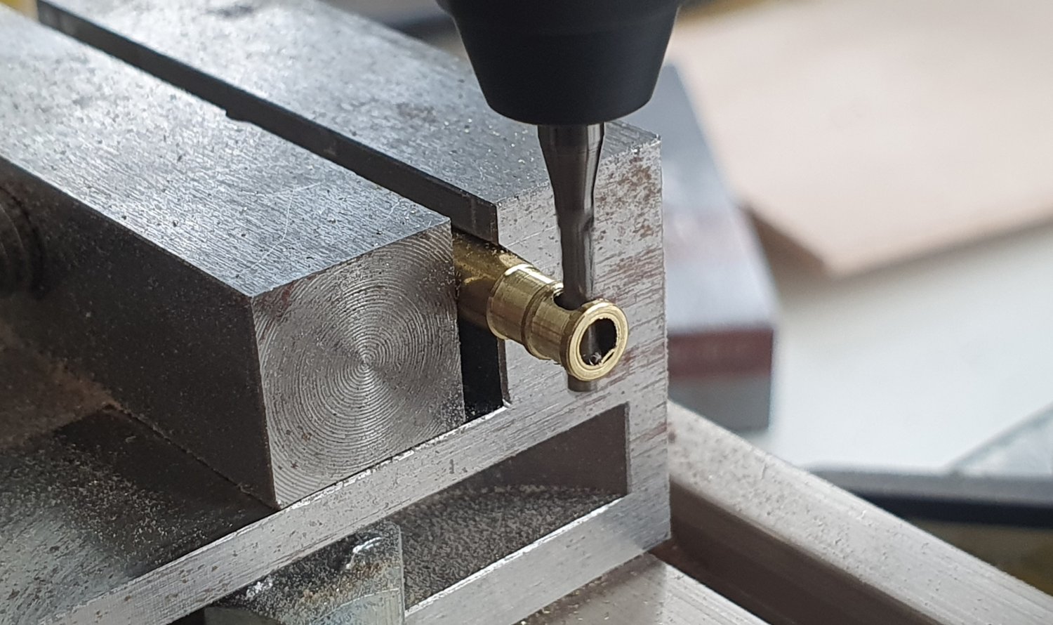
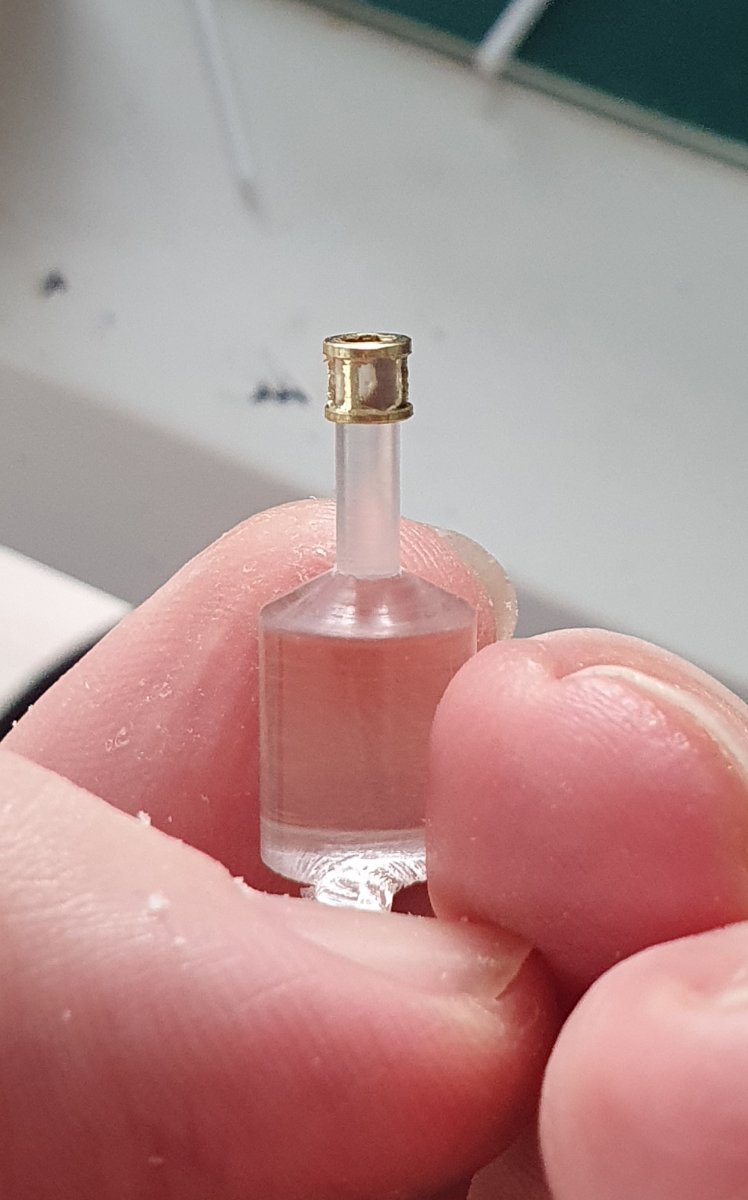
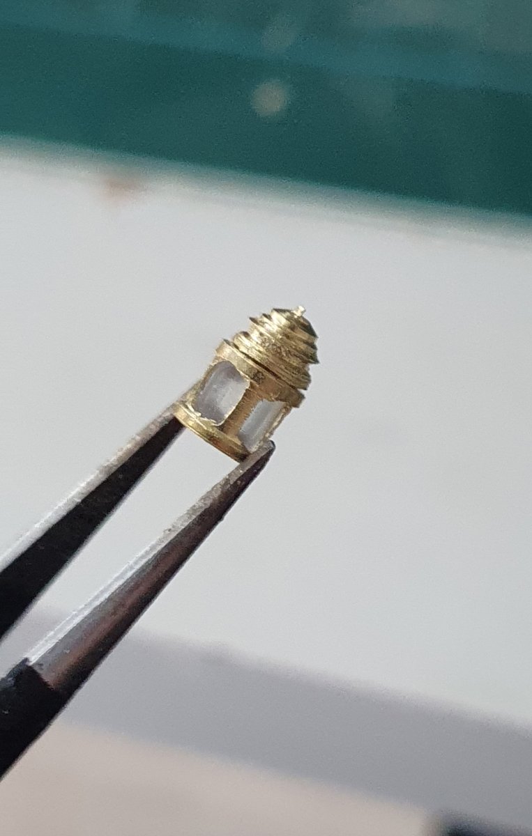
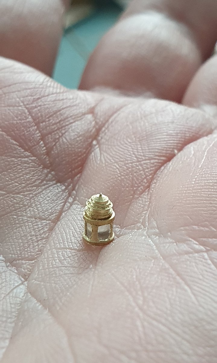
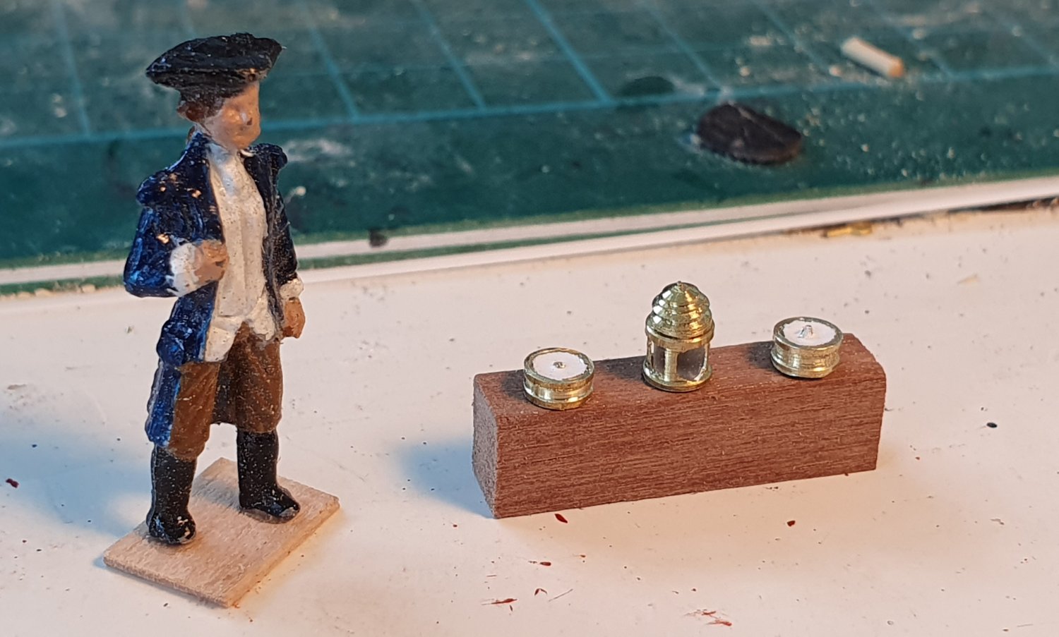
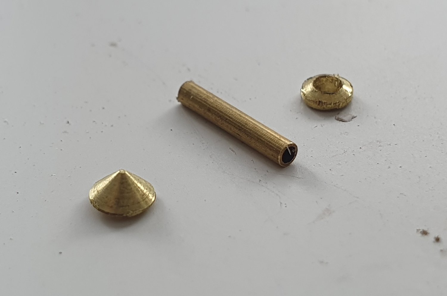
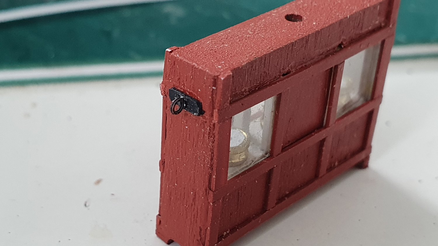
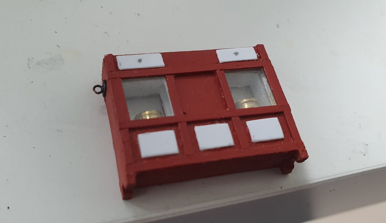
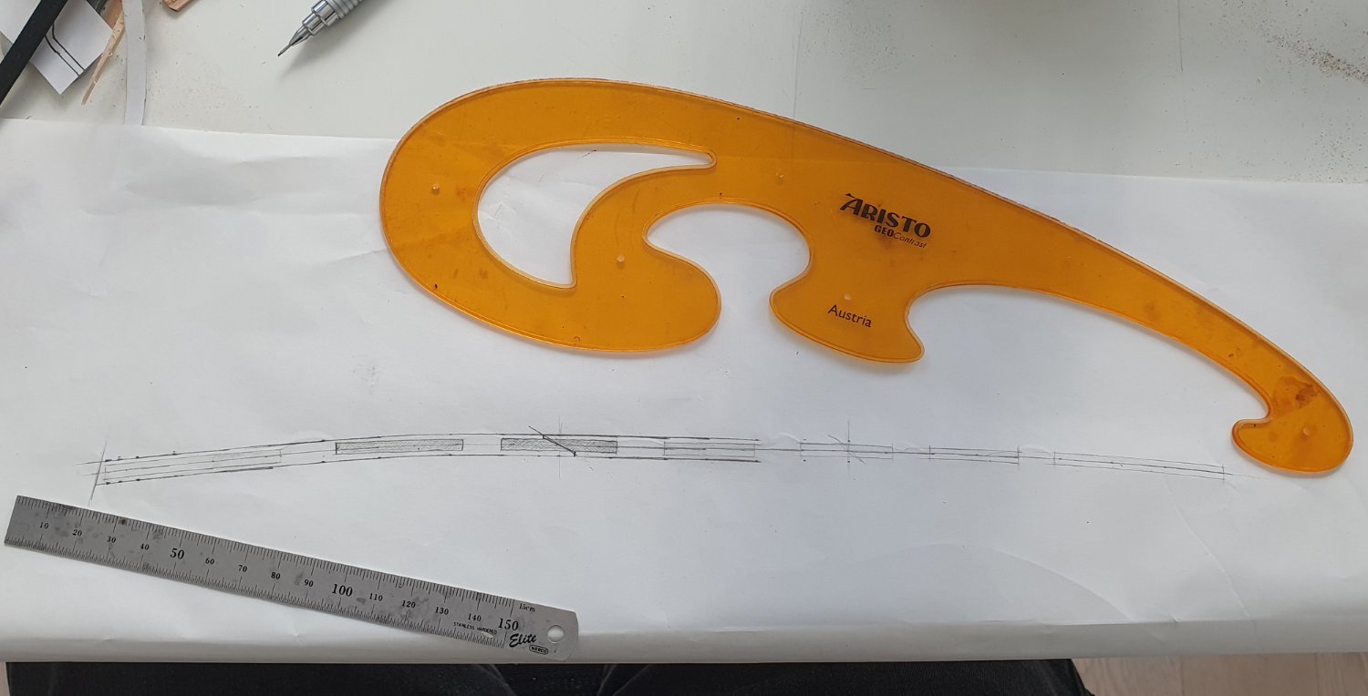
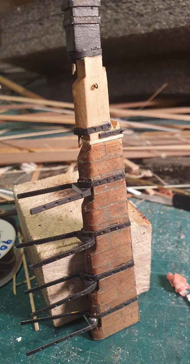
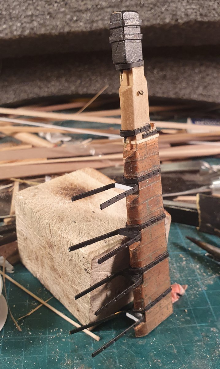
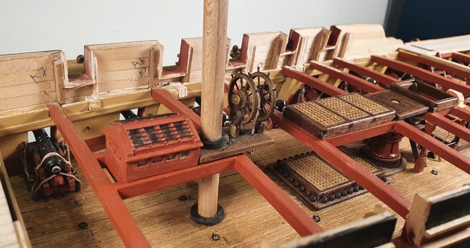
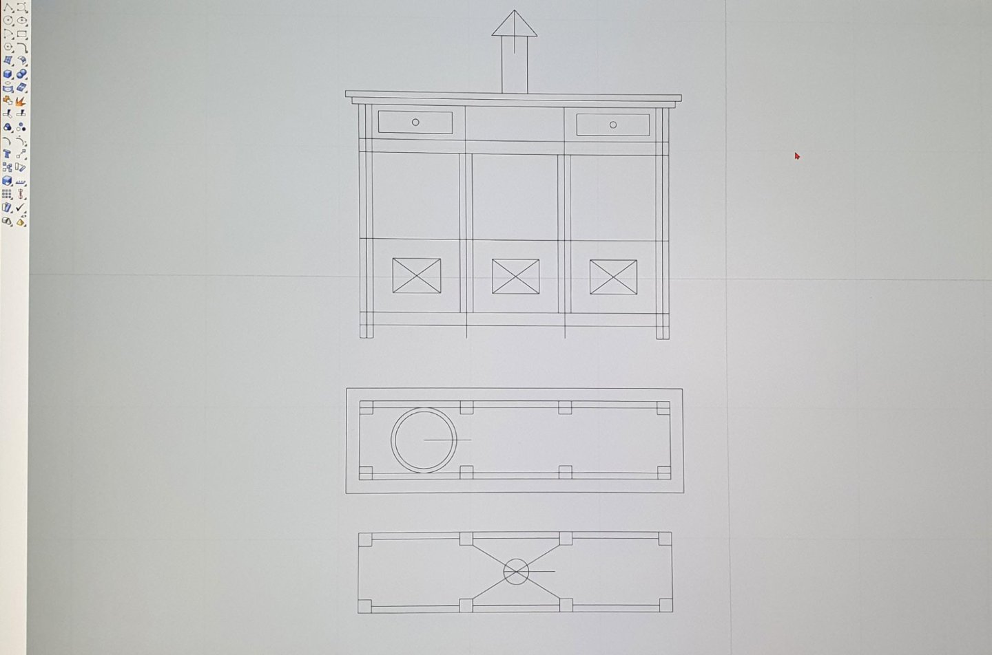
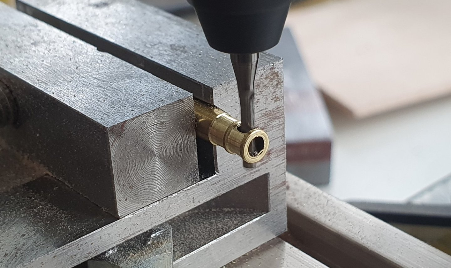
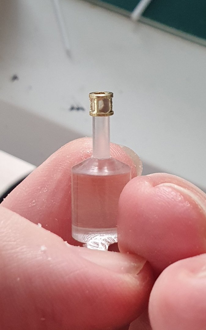
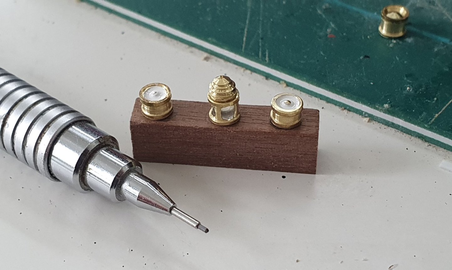
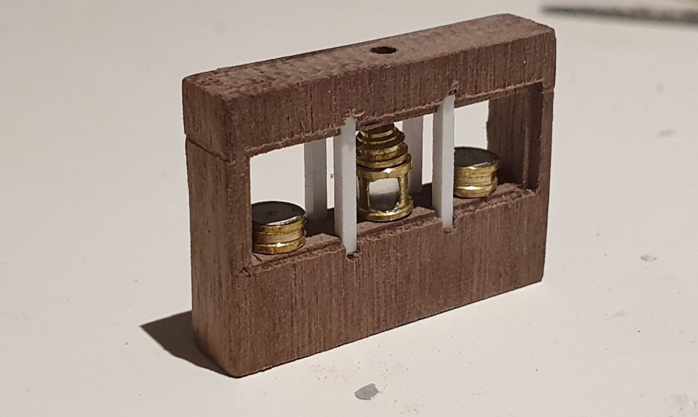
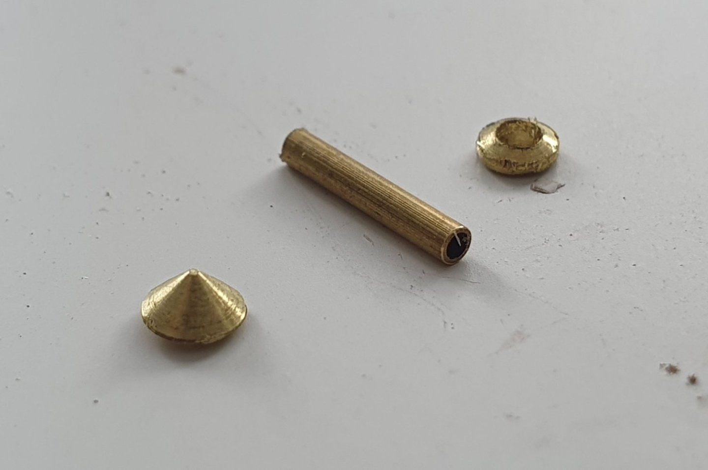
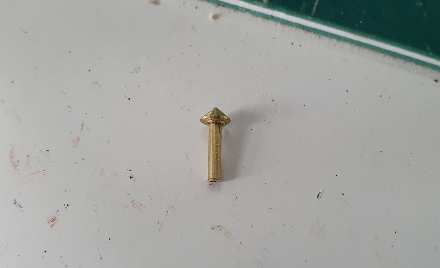
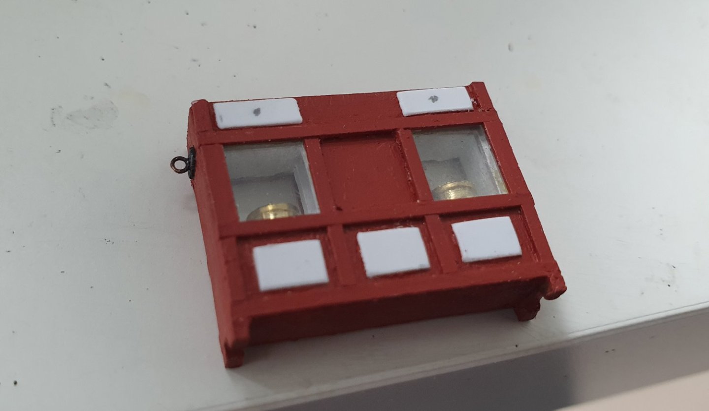
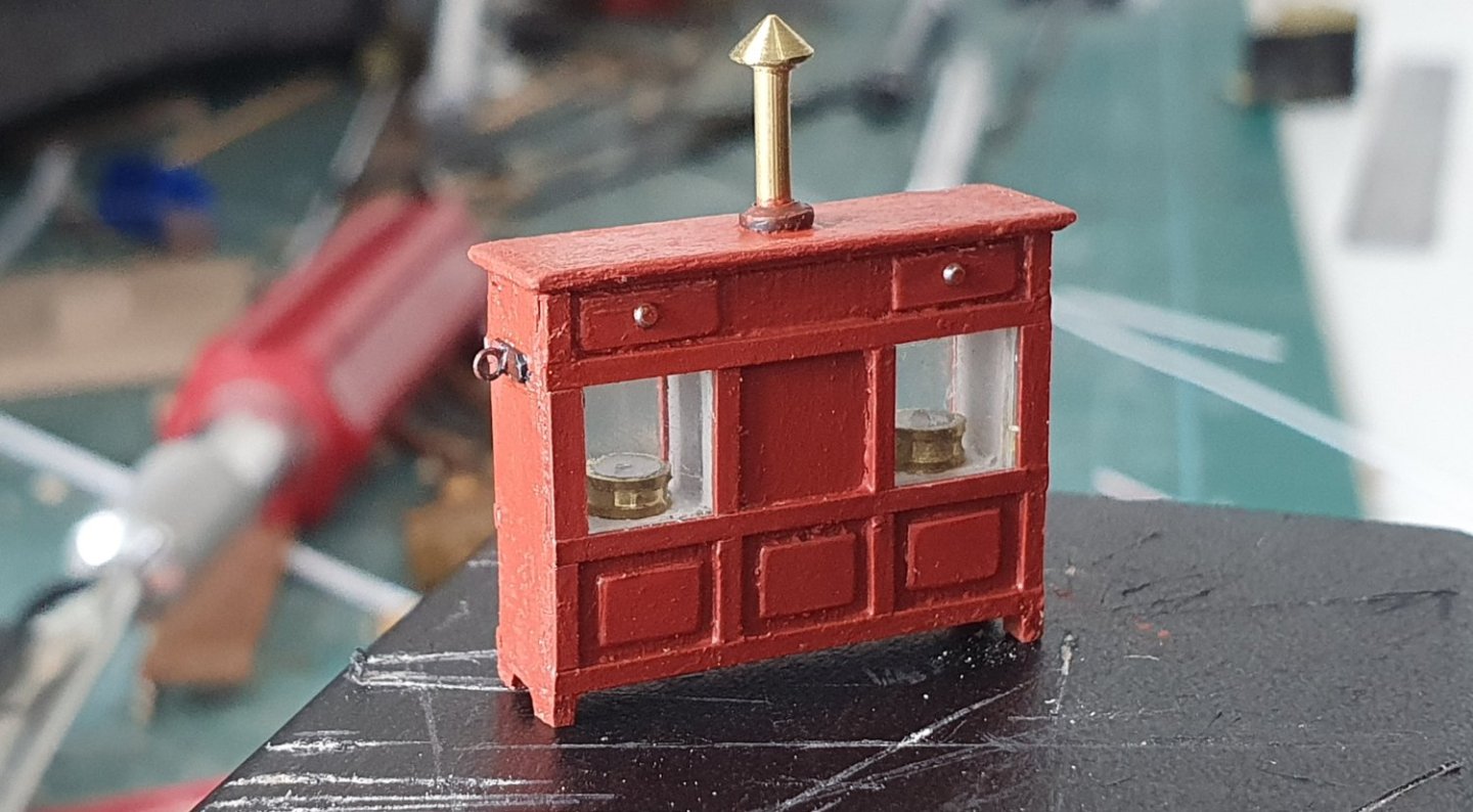
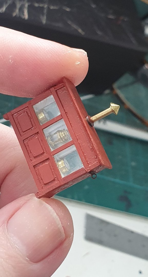
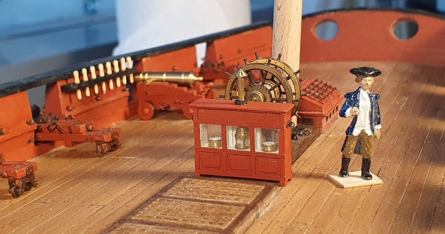
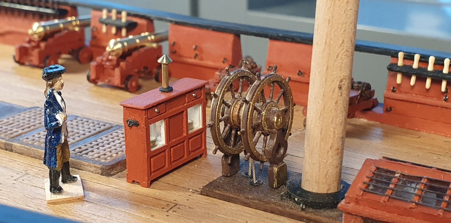
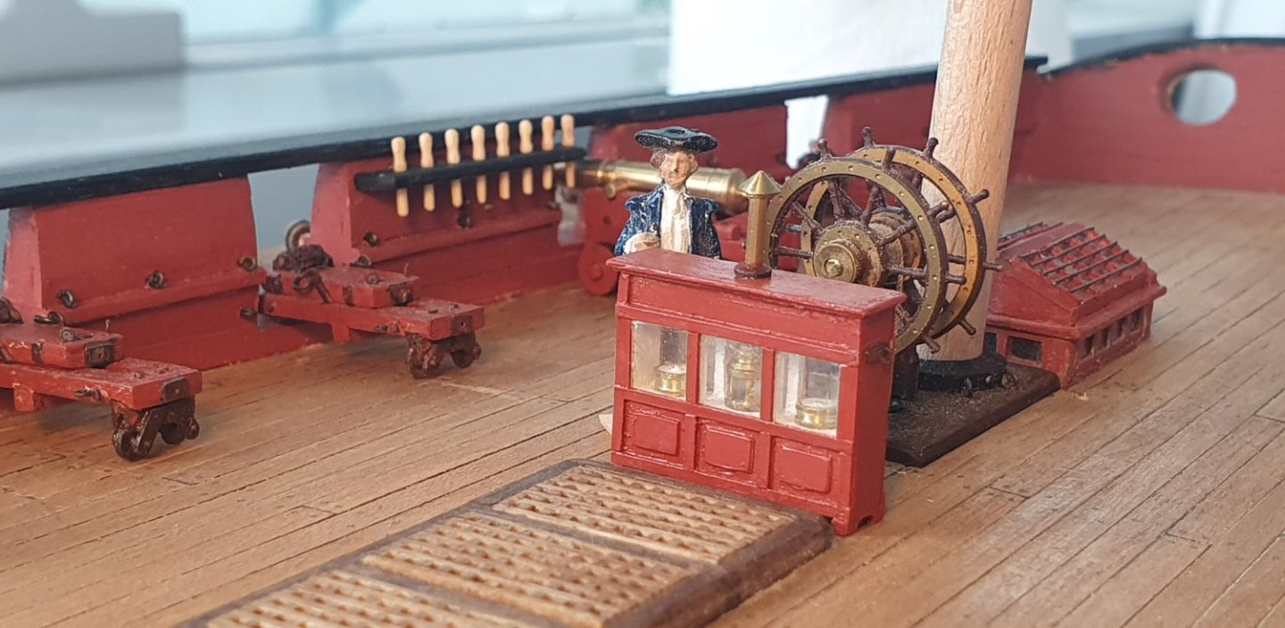
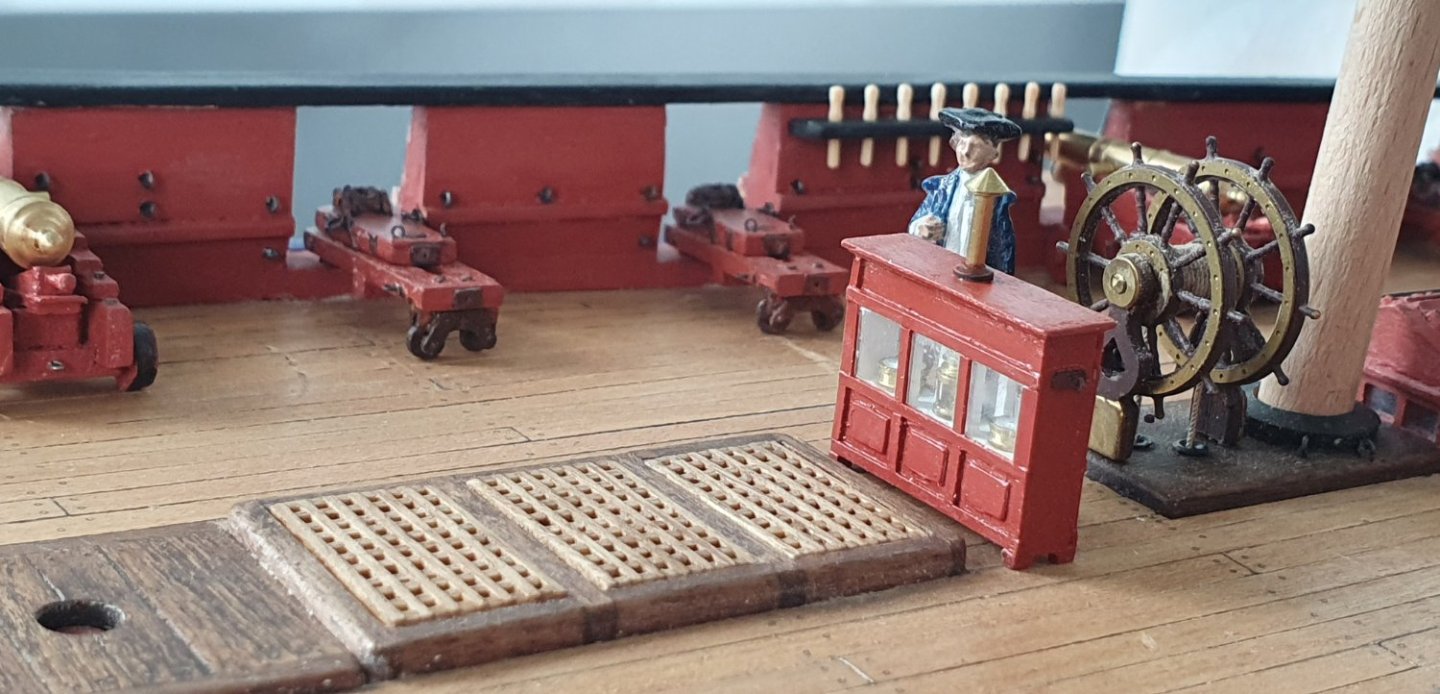
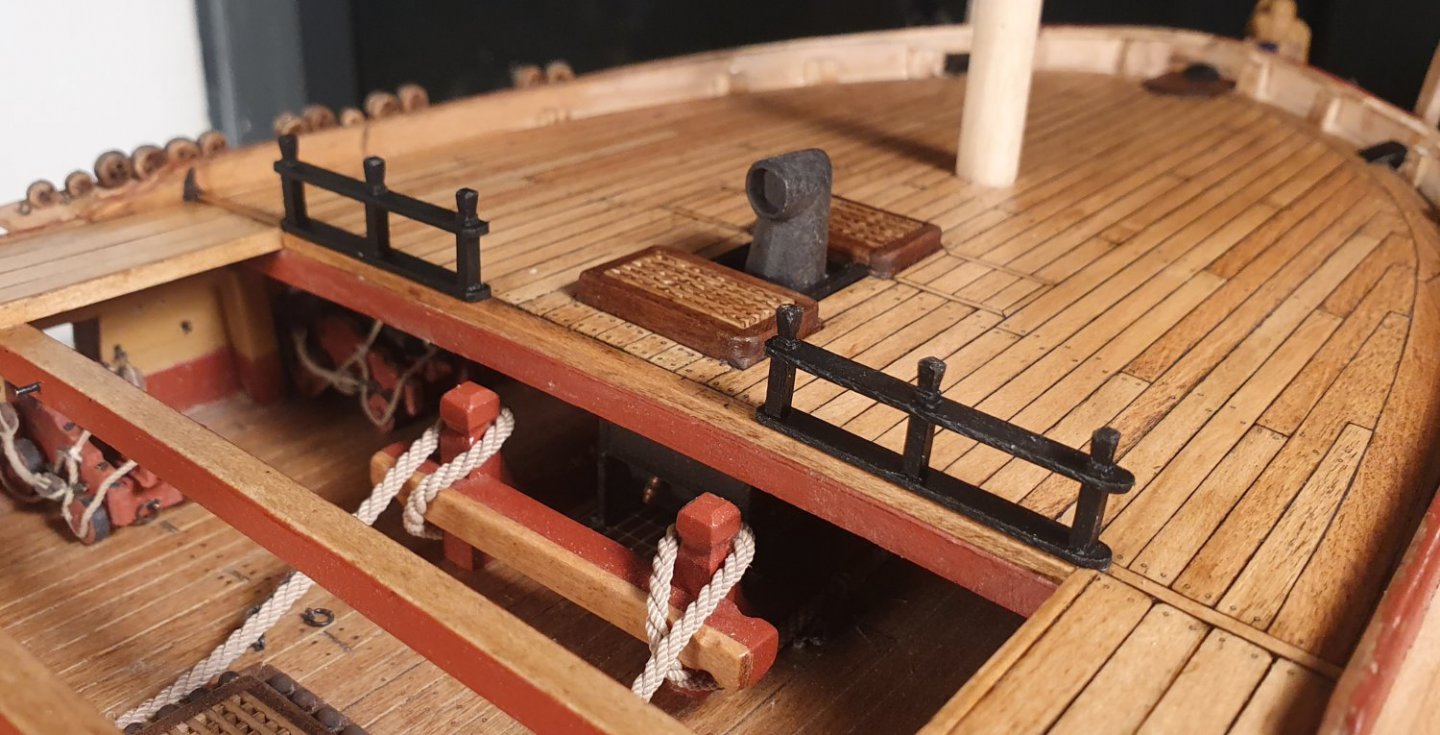
The work on the quarterdeck continues. I have come to realise that there are no easy wins when it comes to the quarterdeck. Everything I attempt is taking a lot longer than envisaged. I decided that I should have a binnacle. There is not one included in the kit but I noticed that most of the other builders include this item and I think it will be a good addition to the quarterdeck. The Vanguard mini kit seems to be the default position but I do not have the patience to wait for the postal service. It is a fairly simple box so I should be able to knock one of those out in an afternoon (this did not happen). I started out with a rough drawing to get the overall dimensions. I based the design on the Victory binnacle but made it slightly larger to give me a fighting chance. I formed the basic carcass out of two pieces of 5mm thick walnut that I glued together. I milled out a 0.38mm deep reveal to accept the glazing. I then added 1x1mm styrene frames and painted the inside of the cabinet white. I decided that I would have to include a ship's compass and lantern as there is a possibility that these would be visible through the glazing if I managed to keep the acetate clear of glue, which would be a first. For the compass I ran some 4mm diameter brass rod through the lathe and cut some notional detail to try and make it compass like. I added a splash of white paint to the top to imitate the face. I made several of these gradually reducing their height. I should have gone down another 0.6mm but I was fed up at this stage. The lamp was a lot fiddlier. I milled a slot on four sides of a 4mm diameter brass tube with the remaining material forming the lamp structure. I could have done this a lot more accurately if I could have roused myself to set up the dividing attachment but I was too lazy and just tried to eyeball it once again proving how wonky my eyes are. I was not too fussed as it will be barely discernible on the final model. This is also the reason I couldn't be bothered tidying up the edges. For the lamp glass I somewhat wastefully lathed a 10mm diameter acrylic rod down to a 3mm diameter and then inserted it into the cage. The capping piece was just freehand lathe work on the 4mm diameter brass rod. Once my ropey looking equipment was installed in the case it was time to start adding some detail to make it look more cabinet like. I used 1.0 x 0.38mm styrene strips to form the mouldings and mullion caps. I added some panels to the 3 divisions of the lower casework and some dummy drawers on the backside using thin styrene with pin nail heads for handles. Just two drawers as a centre drawer would clash with the vent pipe. The glazing was acetate with the centre panel behind the lamp facing the wheel blanked out. I read somewhere, I think in Lavery, that this was the preferred detail to avoid dazzling the helmsman and prevent him steering the ship onto the rocks. The top was cut out of 1mm thick maple with a weak attempt at an edge moulding using a scraper. I have yet to master the correct technique for using the scraper and tend to end up with quite a rough edge. The chimney was constructed out of 1.5mm diameter brass tube with the top cap and bottom collar lathed out of 3.5mm diameter brass rod. These are slippery little suckers and I lost a couple of them to excessive tweezer force never to be seen again. Ringbolts were added to the sides for the tie-down ropes. 1x1mm walnut formed the legs followed by a coat of admiralty red and it was more or less done. I will install it properly later on in the build as it will just get knocked over at this point. Quite a longwinded post for such an insignificant item but it involved a lot more steps than I was anticipating. I am glad to report that you can glimpse the navigational equipment through the acetate so I do not feel like such an idiot for attempting to include it in the first place but rather remorseful that I did not do at bit more research and base them on historical examples but I was just after something shiny in a case.


-
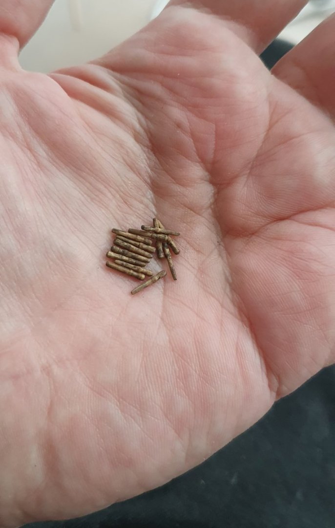
Thanks Jason. I did look to see if I could get aftermarket pins but quite annoyingly all of the vendors I visited did not provide detailed dimensions. The delivery times from the UK have also become very spotty which made me wary of buying a whole lot and waiting two months to find out they were oversized or too chunky so I decided to just press ahead and make my own. I should add that I have now made 65 but only have 64 left as I was gently placing one in the pin rail and squeezed a little too hard with the tweezers causing it to ping down the ladderway and end up in the lower deck where it now exists as an annoying rattle every time I tilt the ship. Regards David
-
Thanks for the kind sentiments Dave but I do not envisage a career hewing belaying pins. 62 is my limit. Anymore and I would consider doing myself in with a toothpick through the heart. Regards, David
-
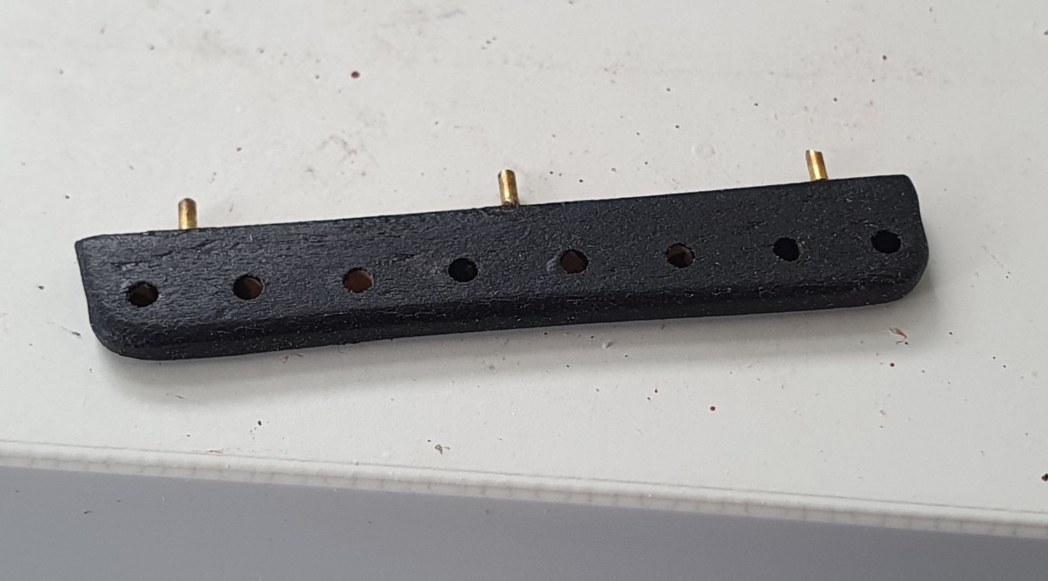
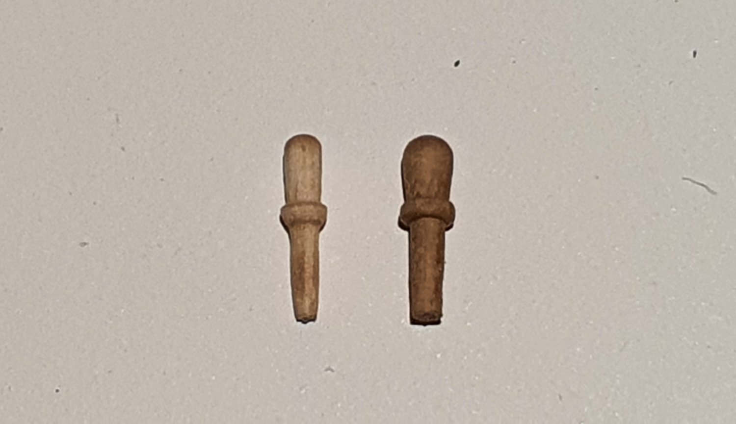
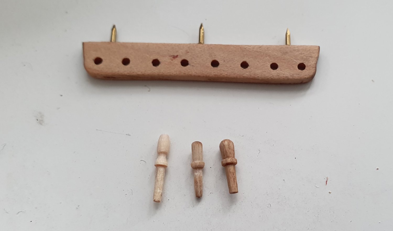
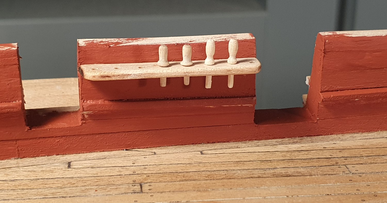
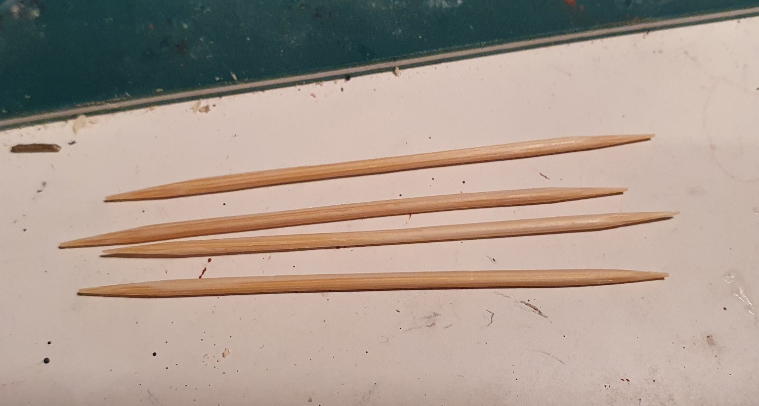
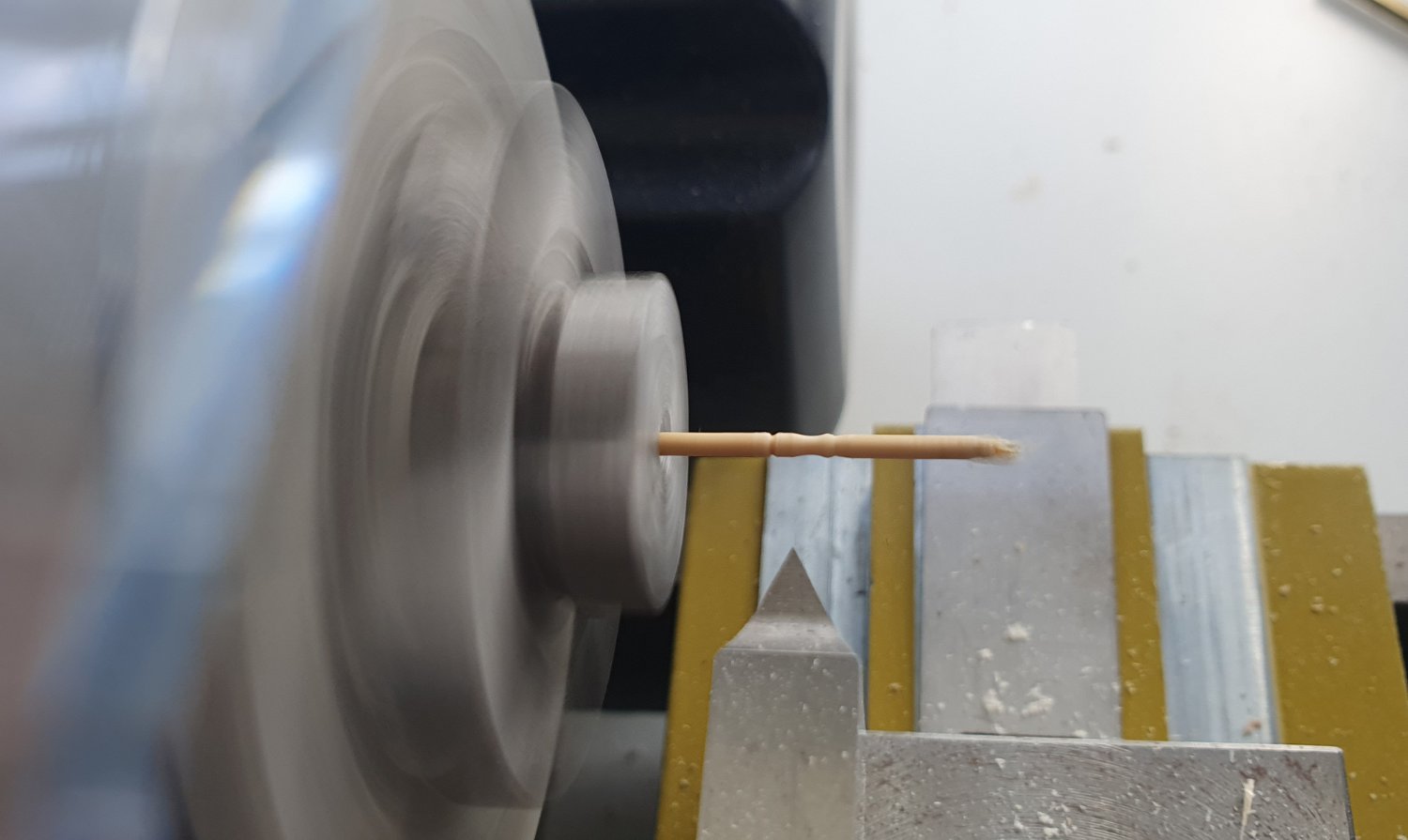
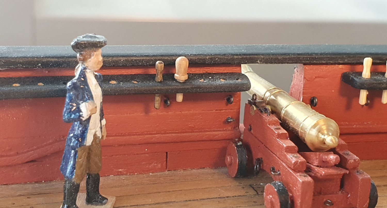
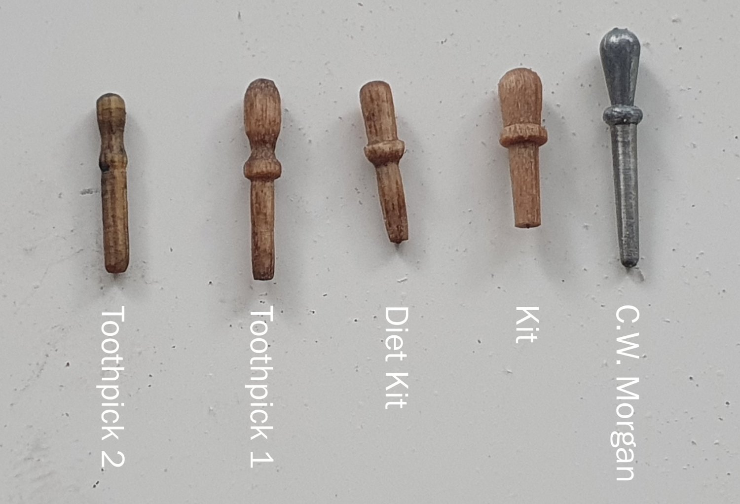
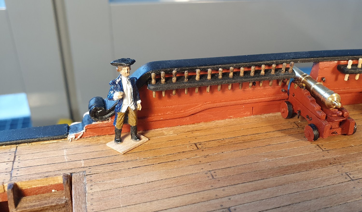
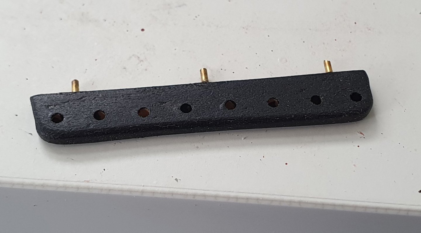
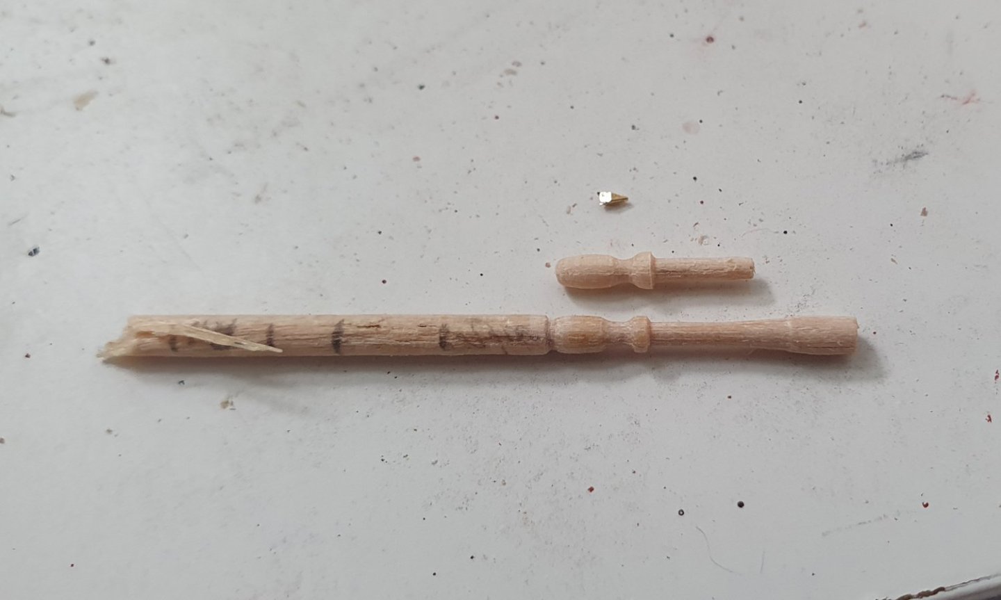
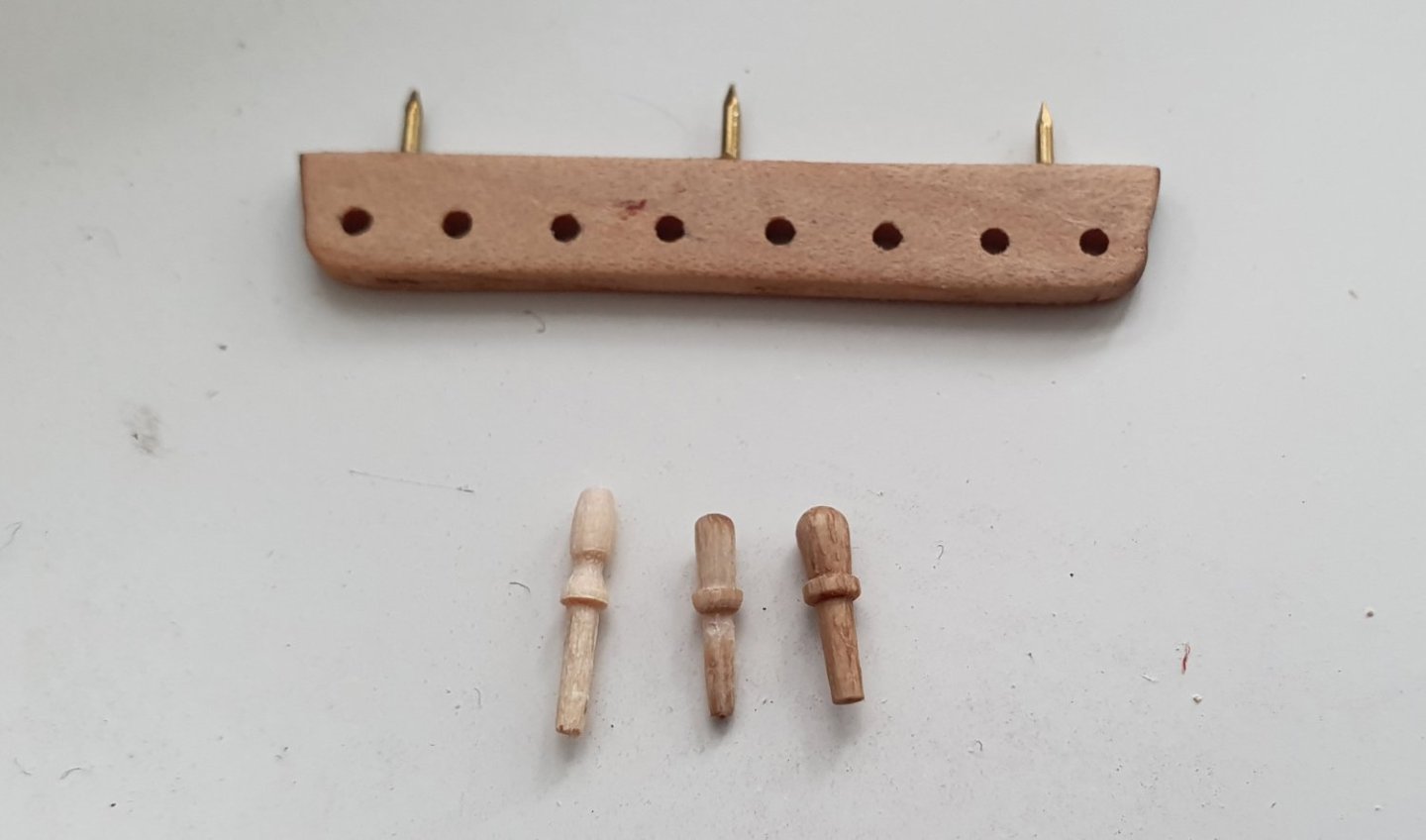
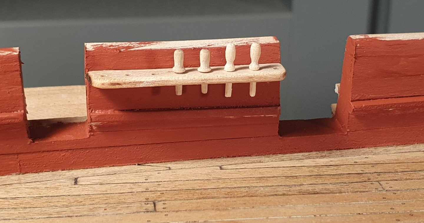
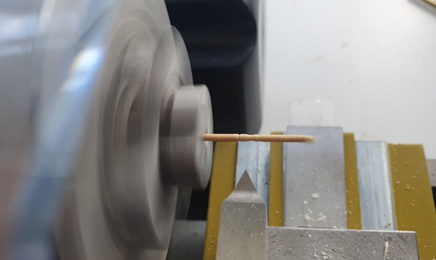
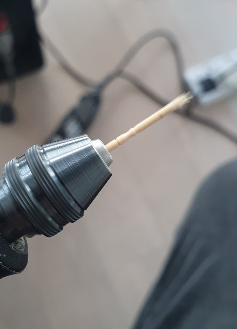
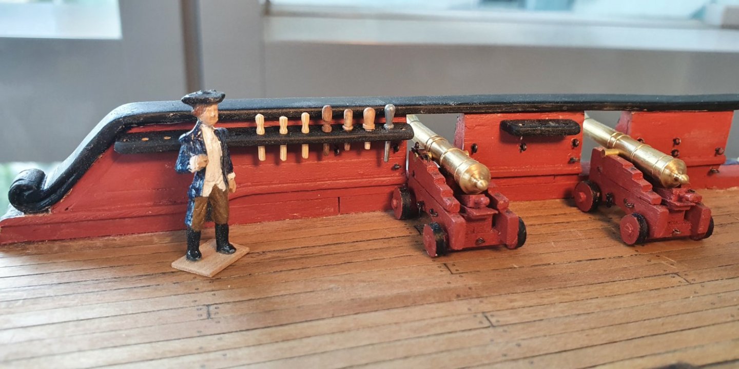
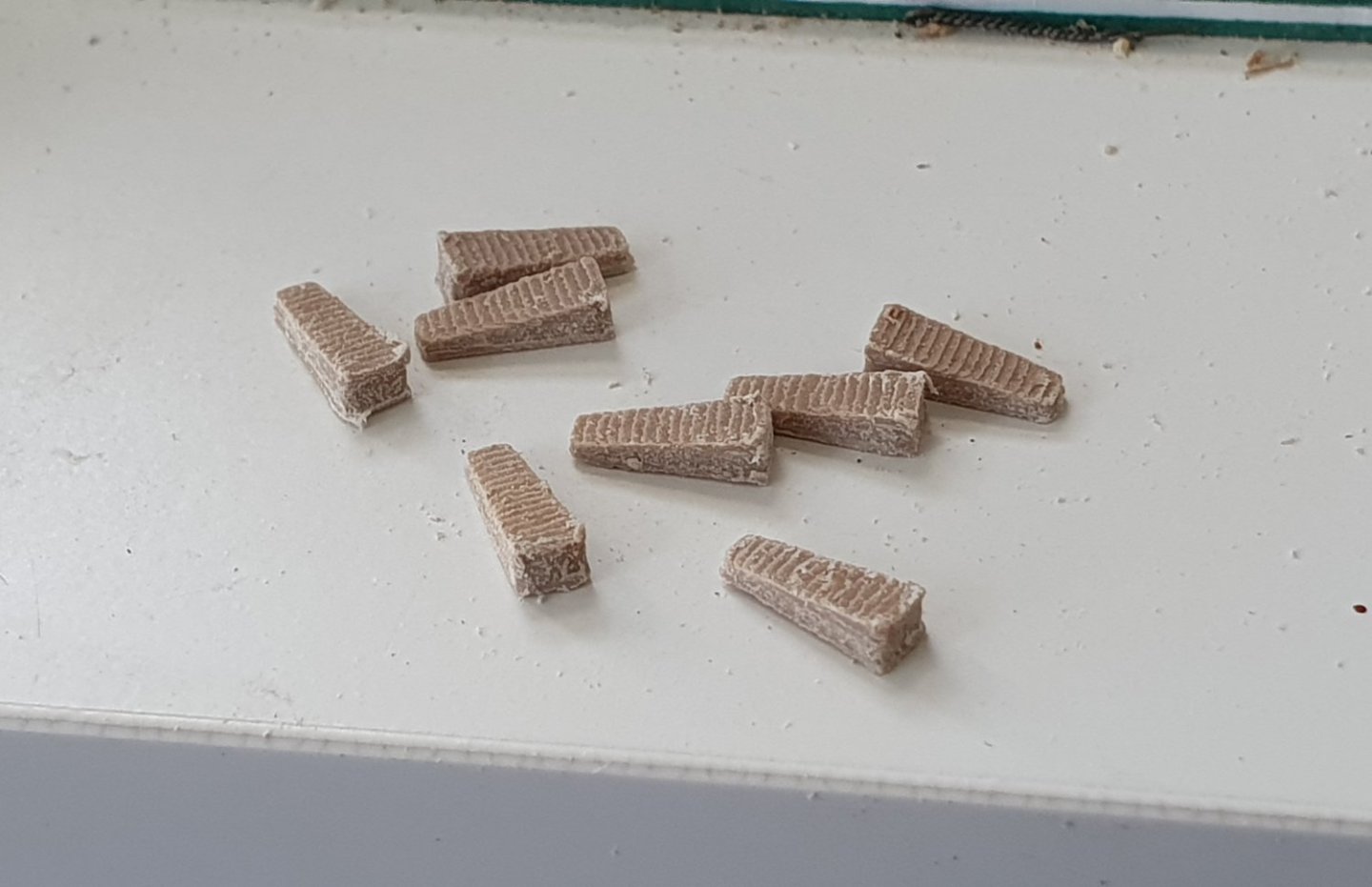
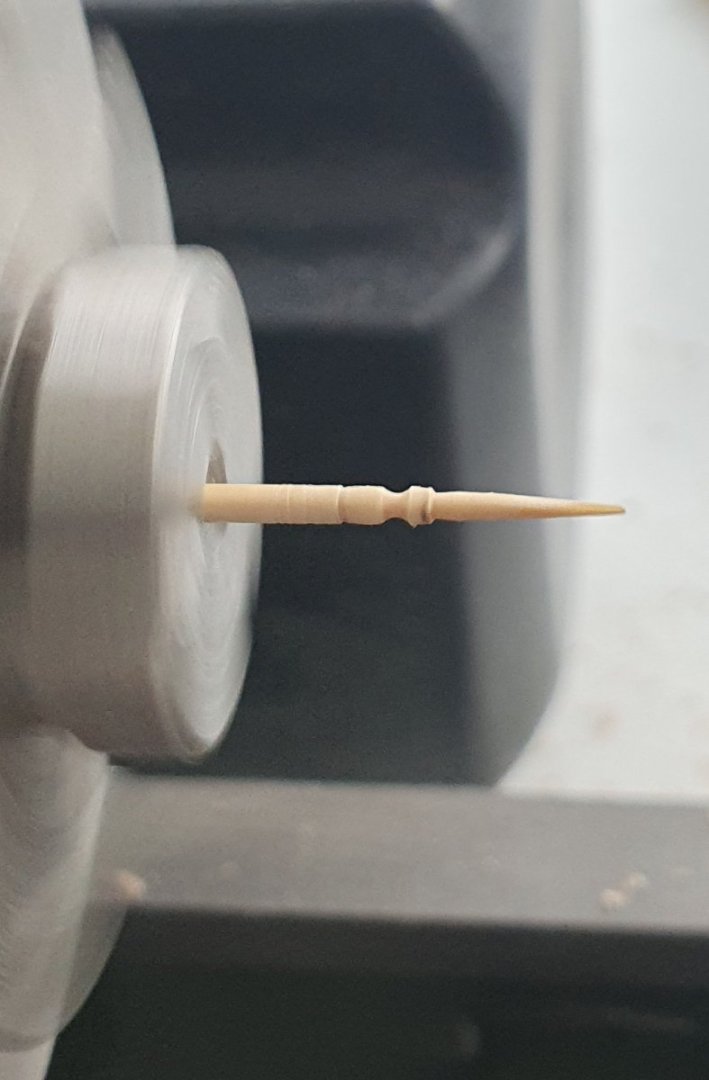
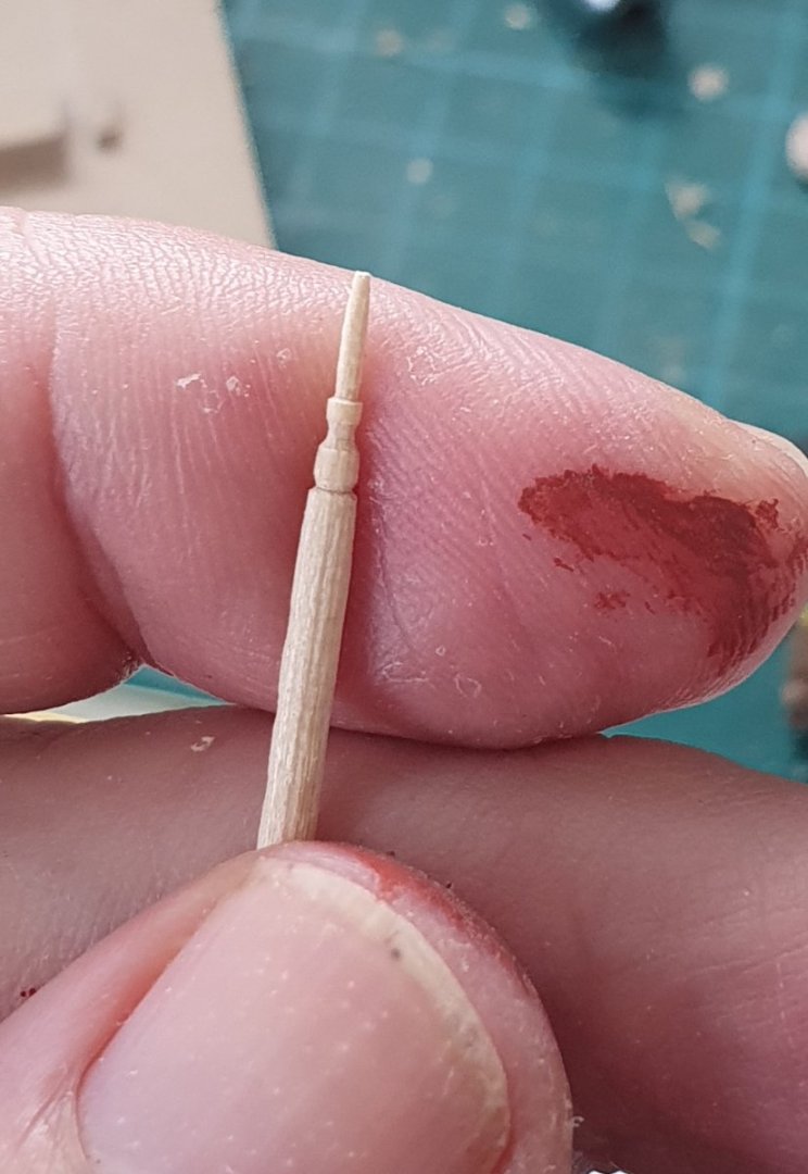
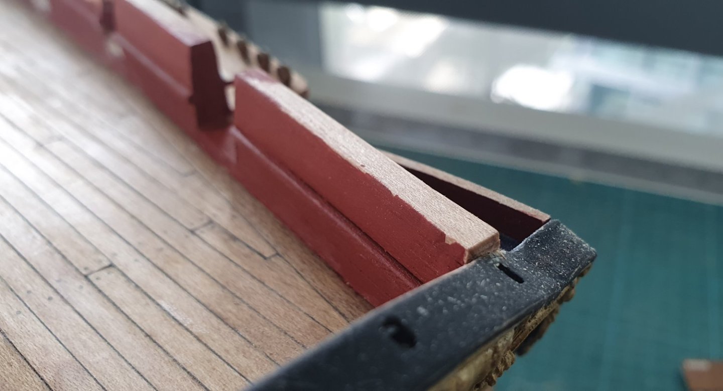
The latest build session did not go to plan. I was focused on completing the bulwarks for the quarterdeck and all of my previous setting out missteps converged to give me no end of headaches. I started off with the installation of the pin rails. Due to my cavalier attitude regarding location of the gunports I had to remake all of these to suit the new dimensions I was faced with. For the forward pin rail I found that I did not have enough room for the required 14 belaying pins. To overcome this I extended the bulwark by gluing on a lump of maple and shaping with the dremel. This led to there being not enough room to accommodate all of the required scrollwork. I still haven't resolved this yet and have made a real pig's ear of the scrolls that I have already installed. I will need to meditate on this to see if I can think of a solution. The top of the bulwark had some pronounced inaccuracies so I had to fashion my rough tree rail as best I could by taking a theoretical centre line through the meandering bulwark and then try to resolve the geometry using a generous offset. I initially went with a 1.6mm thick rail to match the plansheer but after checking the AOTSD and NMM drawings I realised that it scaled to a rail that is 128mm thick which is a handy 2mm at 1:64. I installed it in three pieces as a single 21m length of curved plank did not seem to be feasible. The three pieces added another layer of complexity trying to get the joints and curves to align and it didn't work out great but I am hoping the rigging and hammock cranes will disguise the worst of it. The roughtree rail just peeps out over the top of the taffrail which is a bit sad but the best I could do given the location of the quarterdeck galleries without exaggerating the height of the bulwarks too much. It is at this point that I realised I should probably start again from the beginning armed with the knowledge that I have gained thus far but I have already spent so much time and effort that it would be foolish to walk away. I am just going to have to accept the fact that my ship is quite challenged in the looks department or at best quirky and hope that it develops some personality to compensate. The belaying pins were another item that were are lot more time consuming than I first imagined. The kit supplied items are good quality but way too fat. I tried putting them on a diet by spinning them in the dremel and taking off some excess using sandpaper. It was an improvement but they were still too wide for their height and prone to flying out of the end out the dremel at high speed never to be seen again. I then attempted to make new ones using a toothpick and the lathe. An improvement but still a little top heavy and the toothpicks were quite fragile and fond of breaking at the last minute. I remembered that I had some cast metal pins from my Charles Morgan kit. These have good definition but were a bit too long and the head too bulbous. Getting an acceptable woodlike finish would have also proved problematic. I decided to have another go using a different brand of toothpicks. The new toothpicks are bamboo nominally 1.6mm in diameter and not perfectly round or straight for that matter. I ran them through a drawplate until they were 1.3mm in diameter which improved their roundness. I then used a lathe to form the handle end using a convex needle file. For the final finishing I spun it in the dremel and used sandpaper to reduce the shaft down to a 1mm diameter. They are not the best as no two are the same but they are closer to the proportion I was aiming for. The bamboo does not take a stain so I have to dirty them up using pastels, charcoal and china marker. I must admit that hand carving 62 belaying pins was not in the original budget but I found that if I tackle 10 at a time in a production line manner then it is almost achievable so long as I knuckle down and complete 10 every day for a week. I still need to work on their finish.


-
Thanks Dave. They are tricky little blighters. Regards David
-
Thanks Dave. I will reserve judgement until the perilous rigging component is completed. Regards, David
-
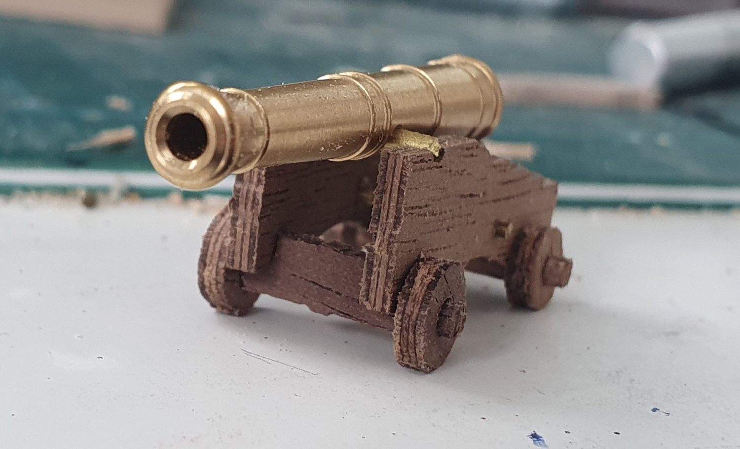
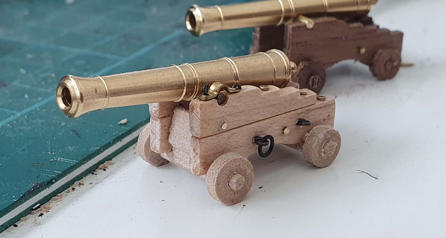
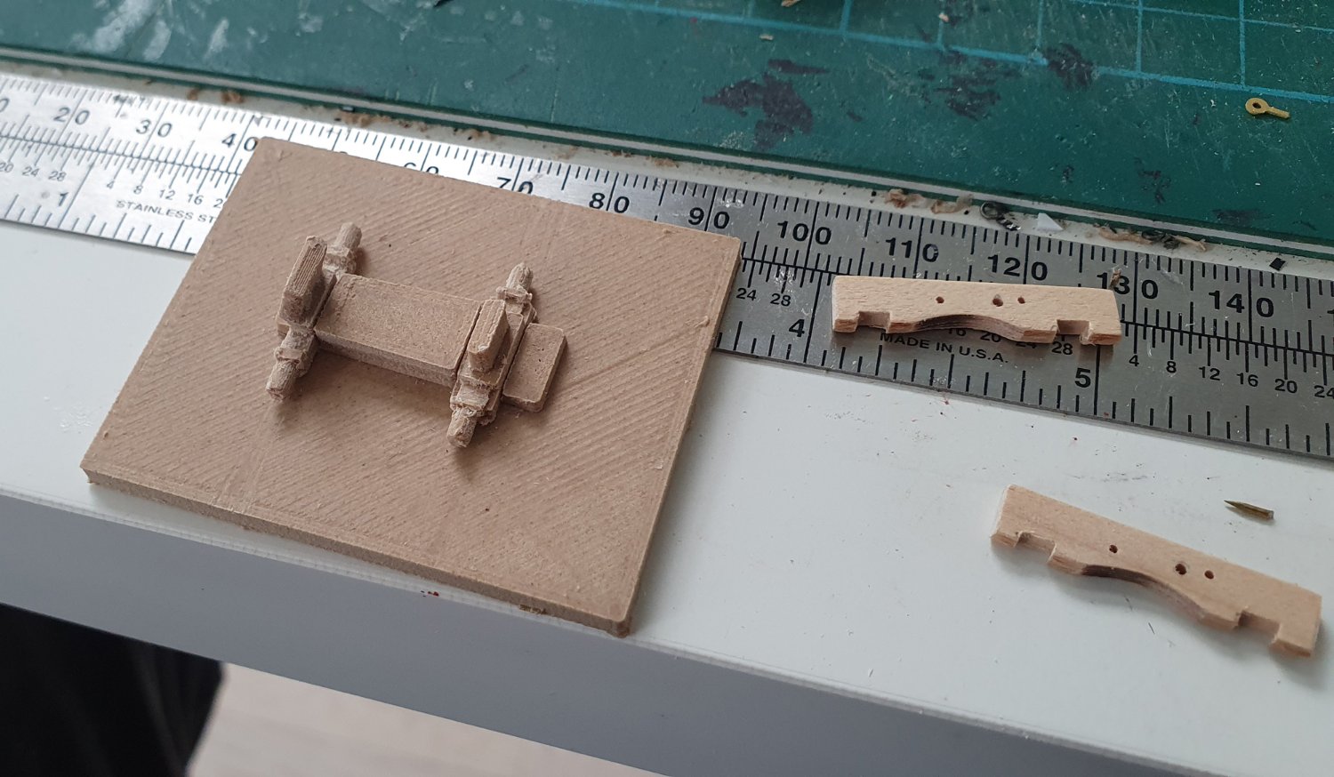
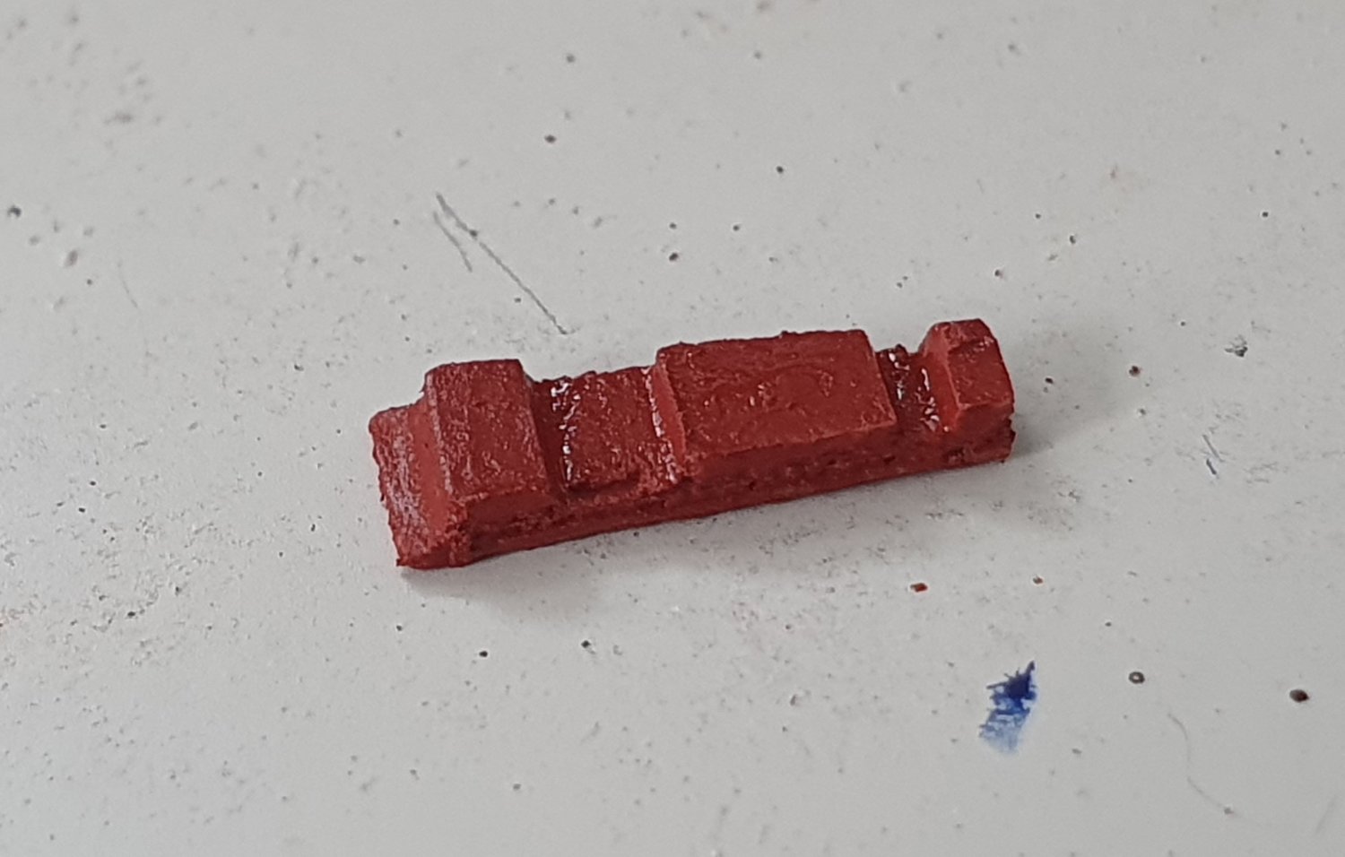
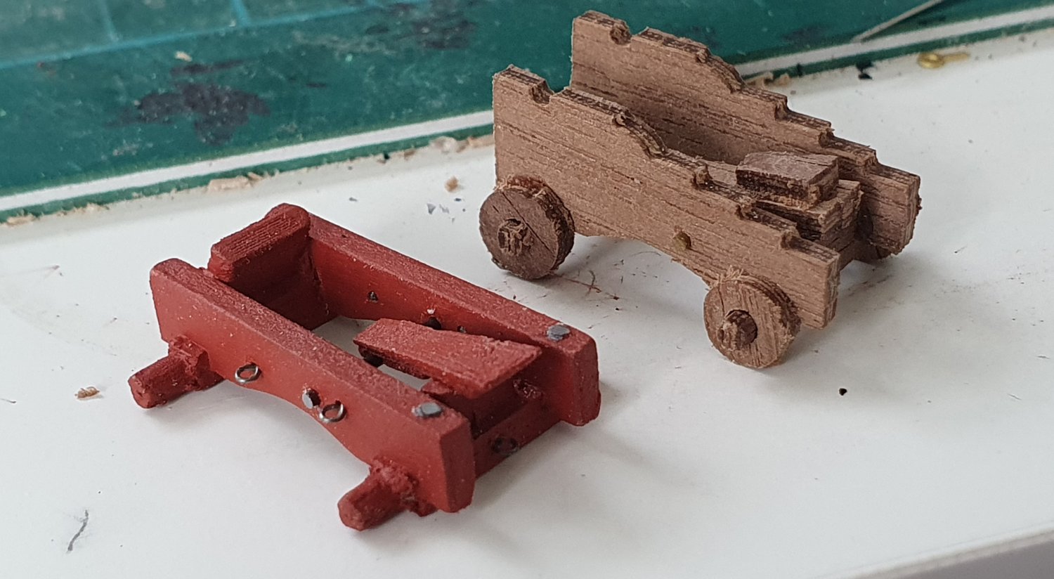
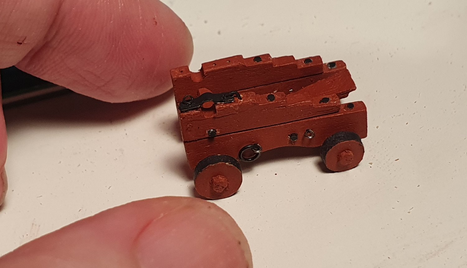
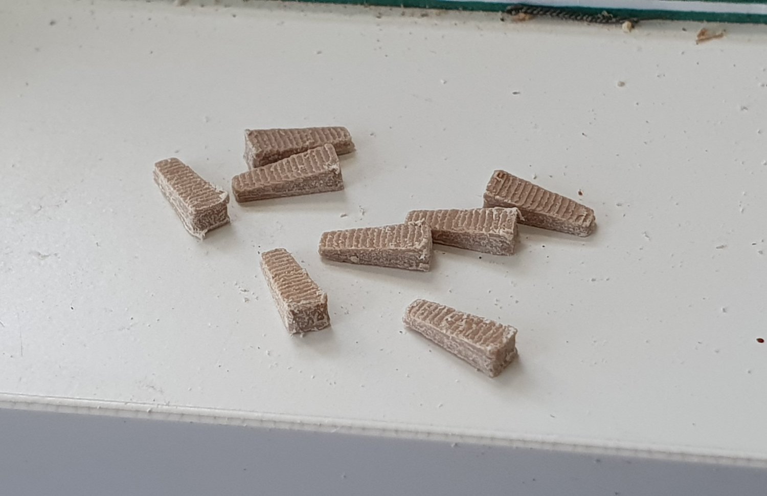
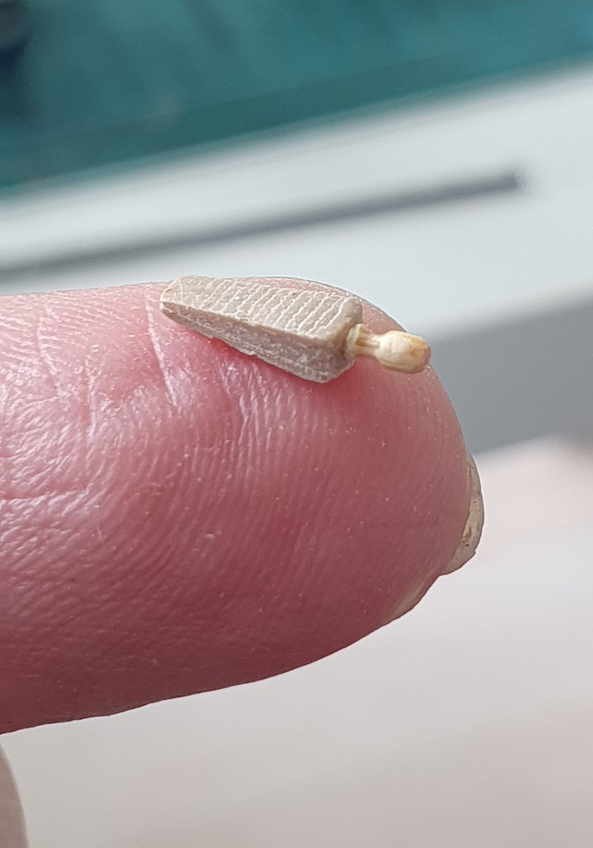
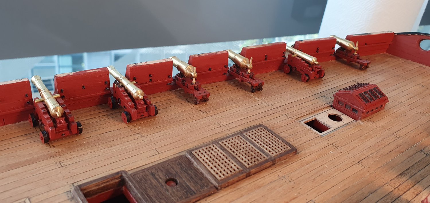
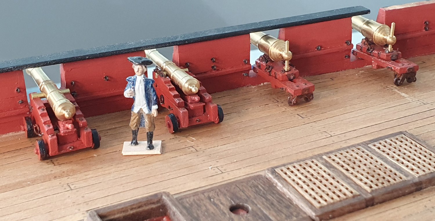
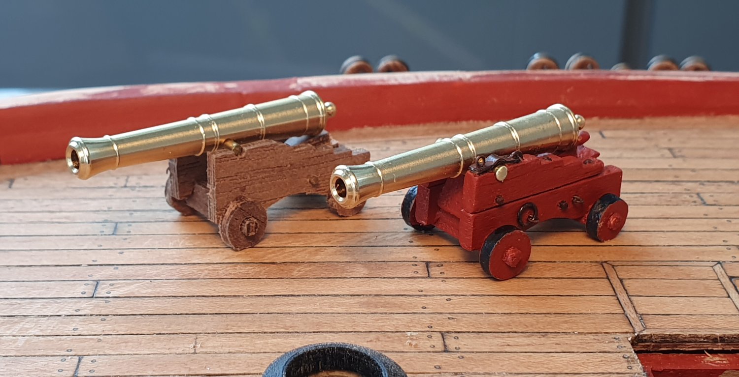
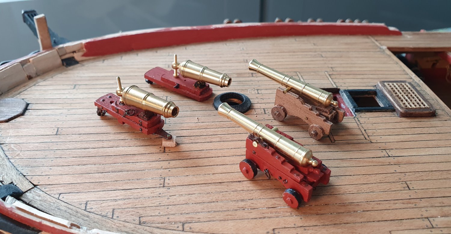
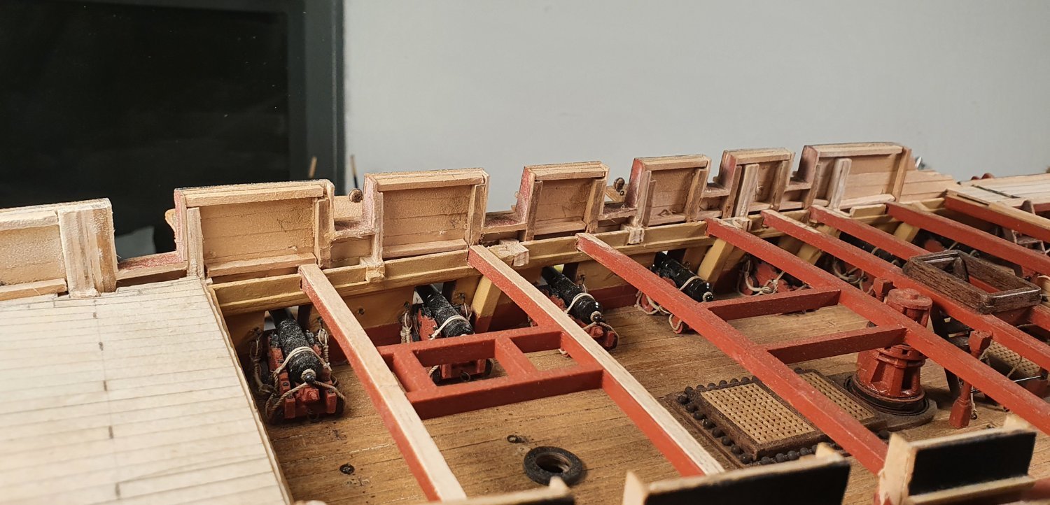
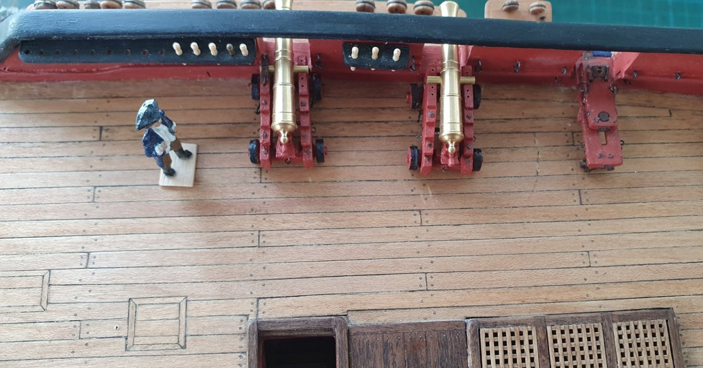
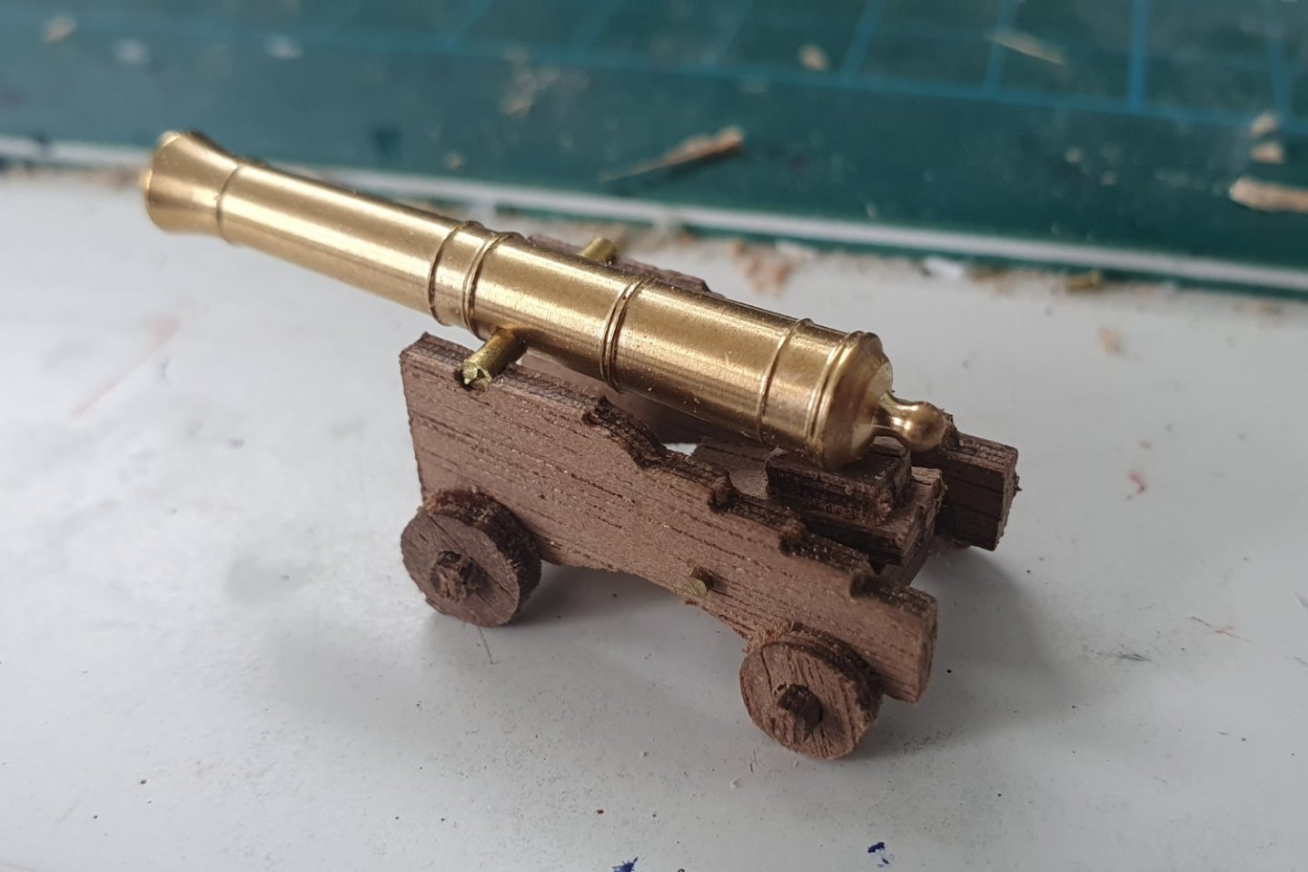
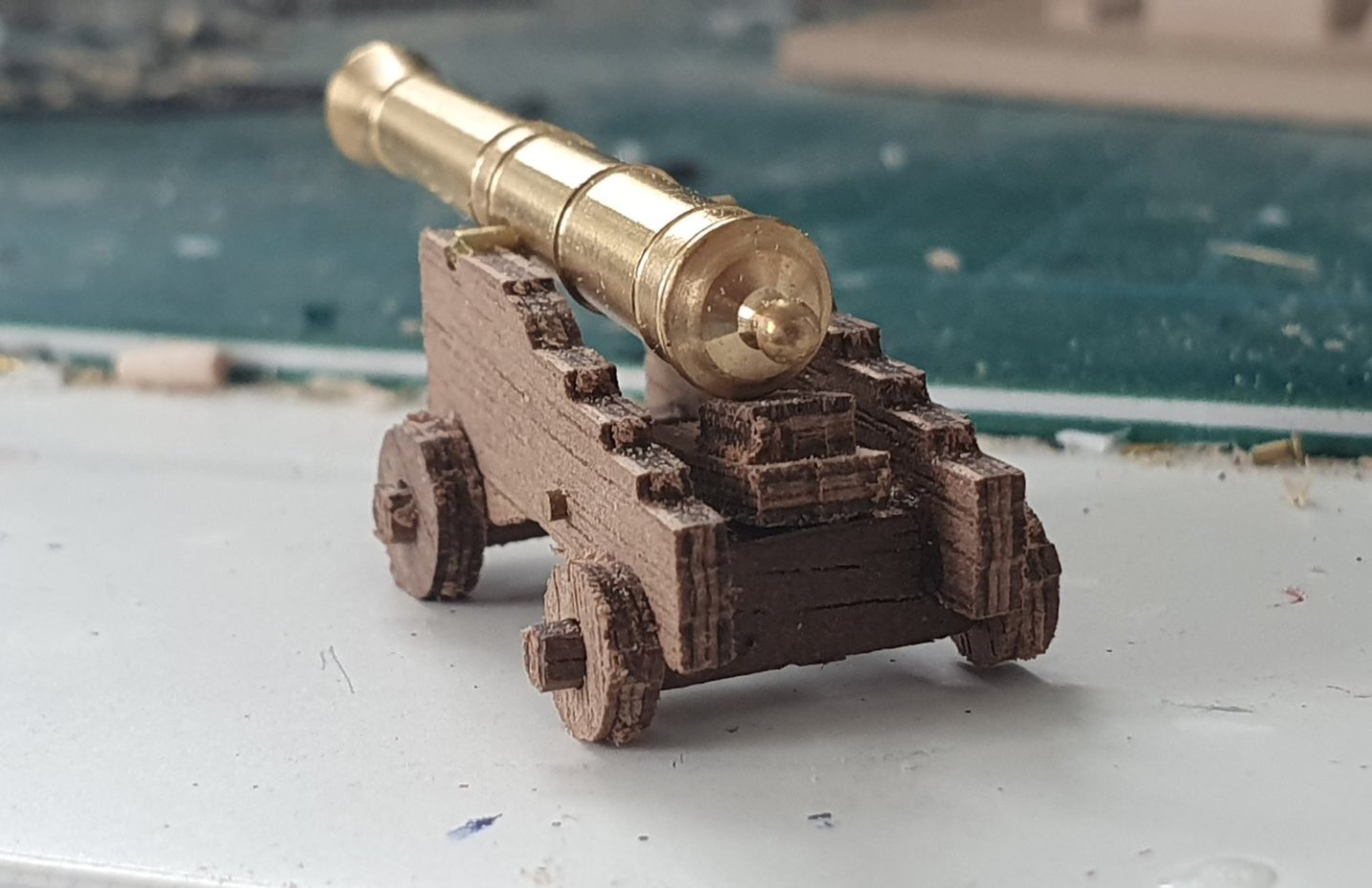
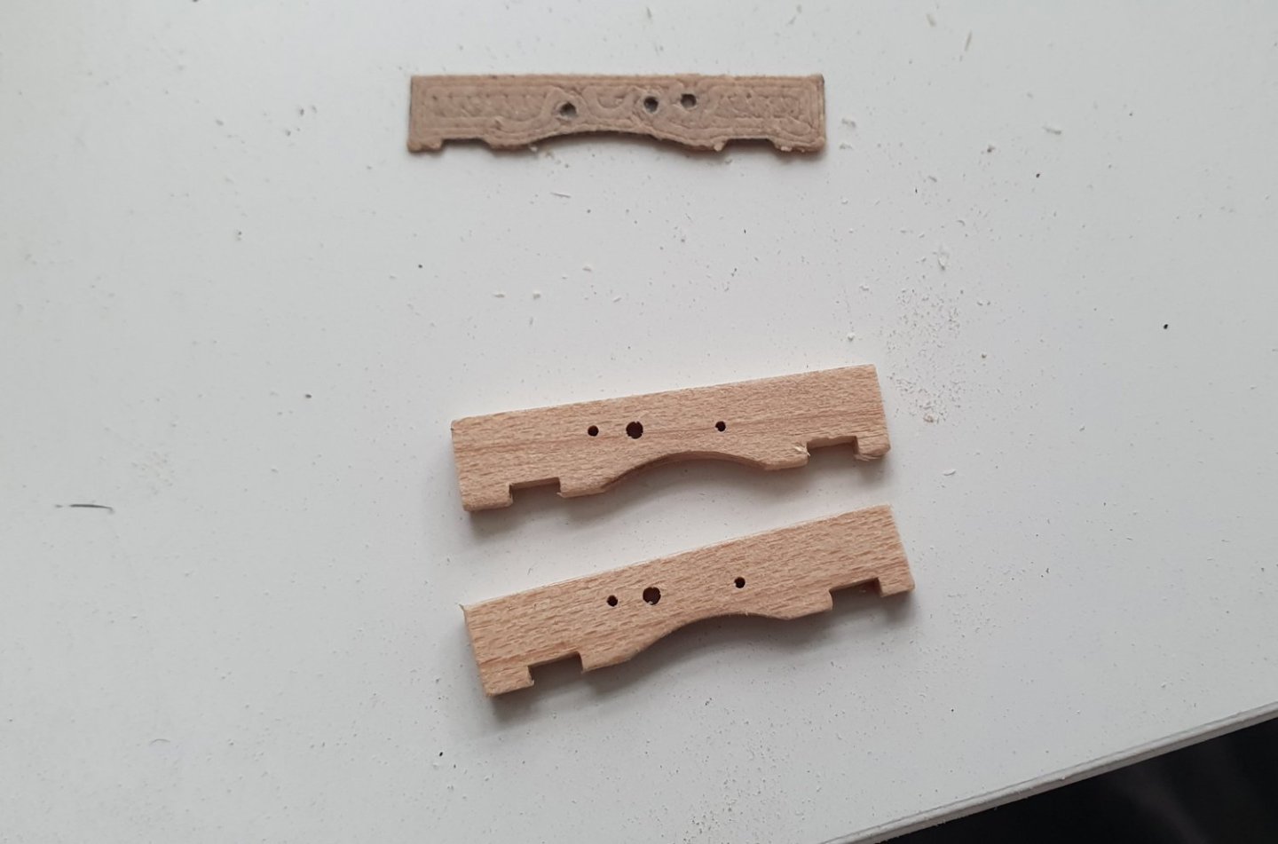
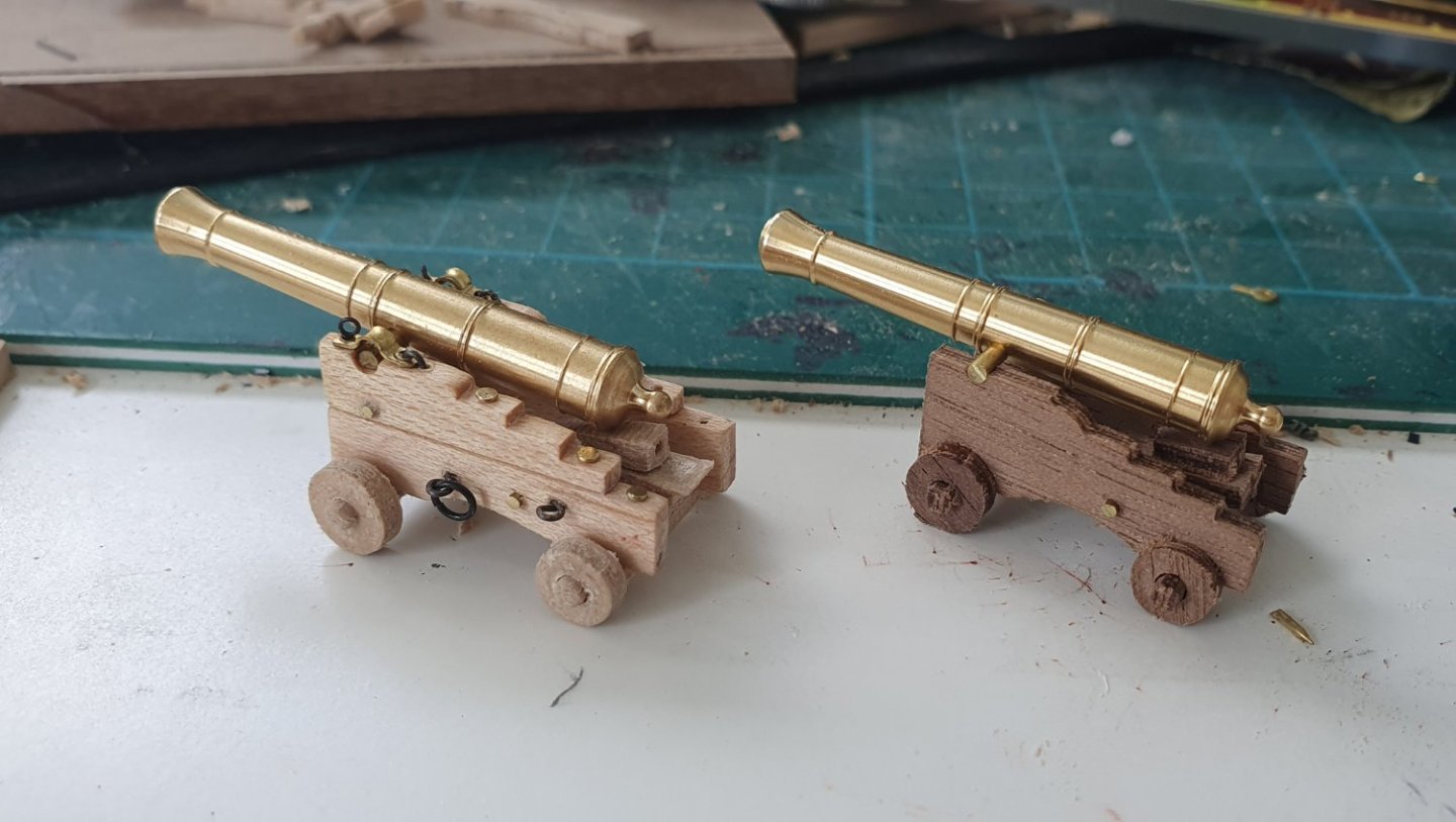
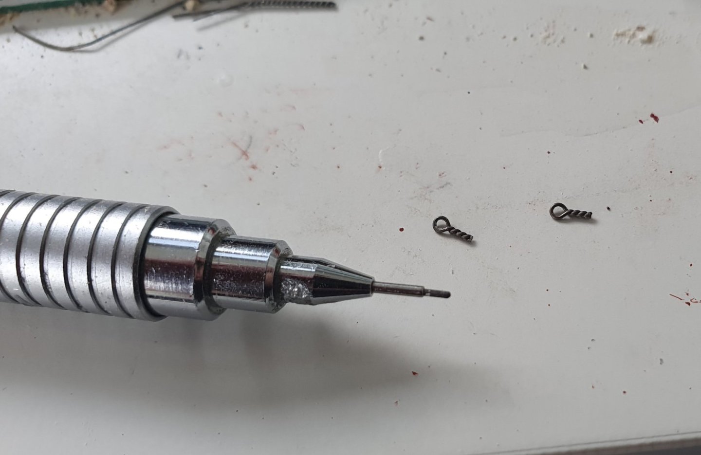
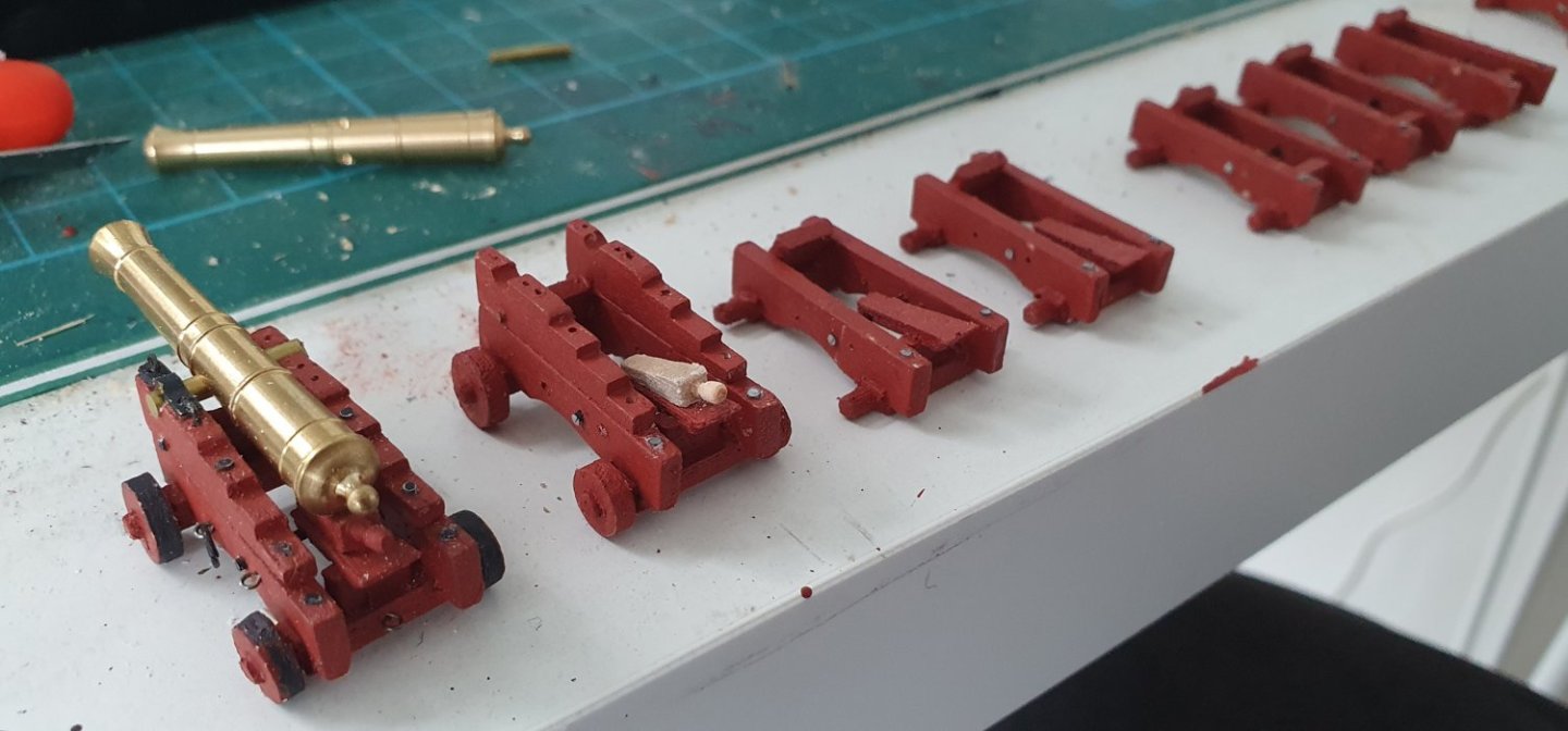
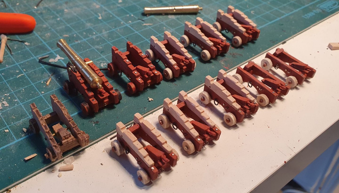
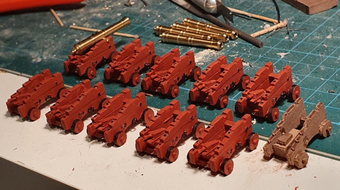
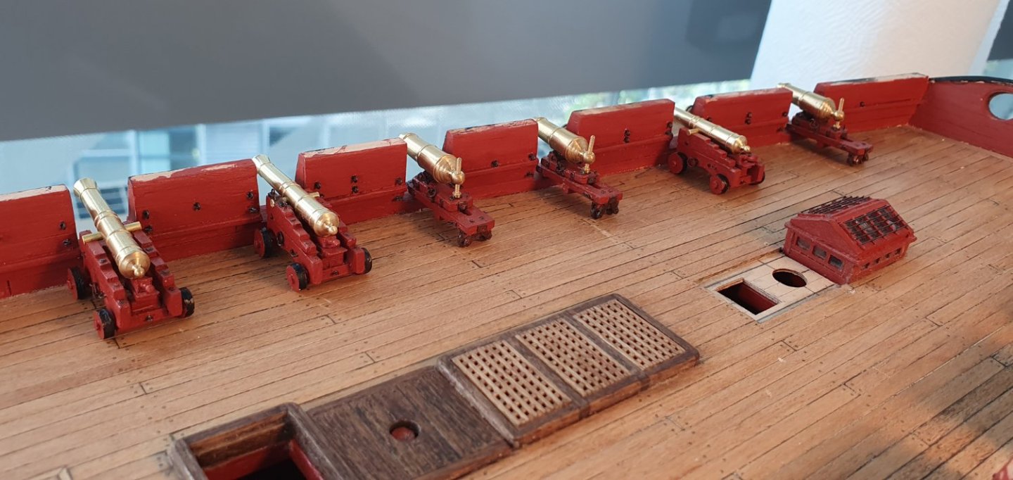
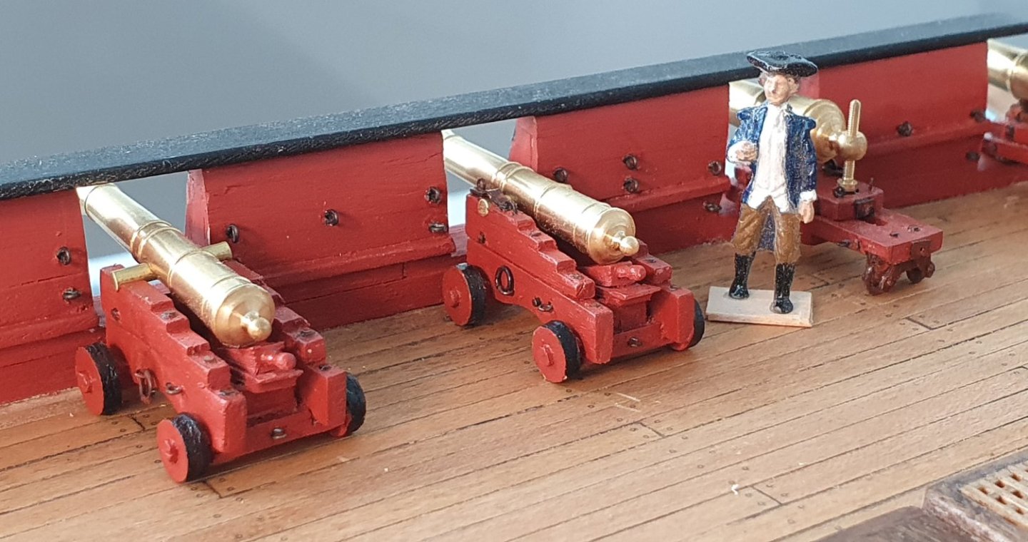
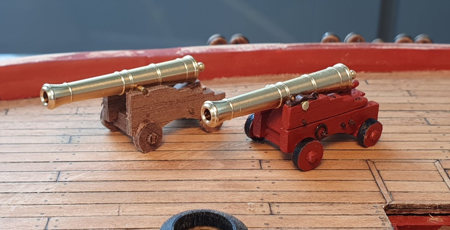
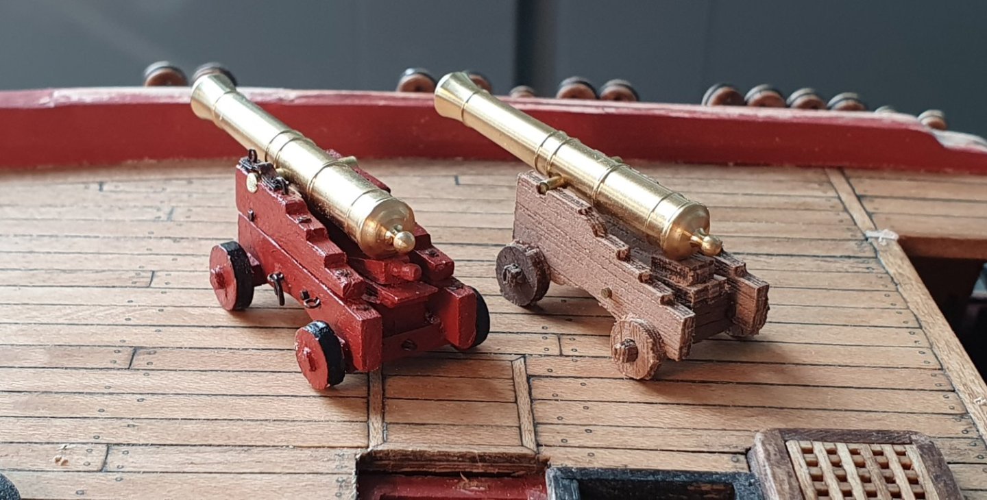
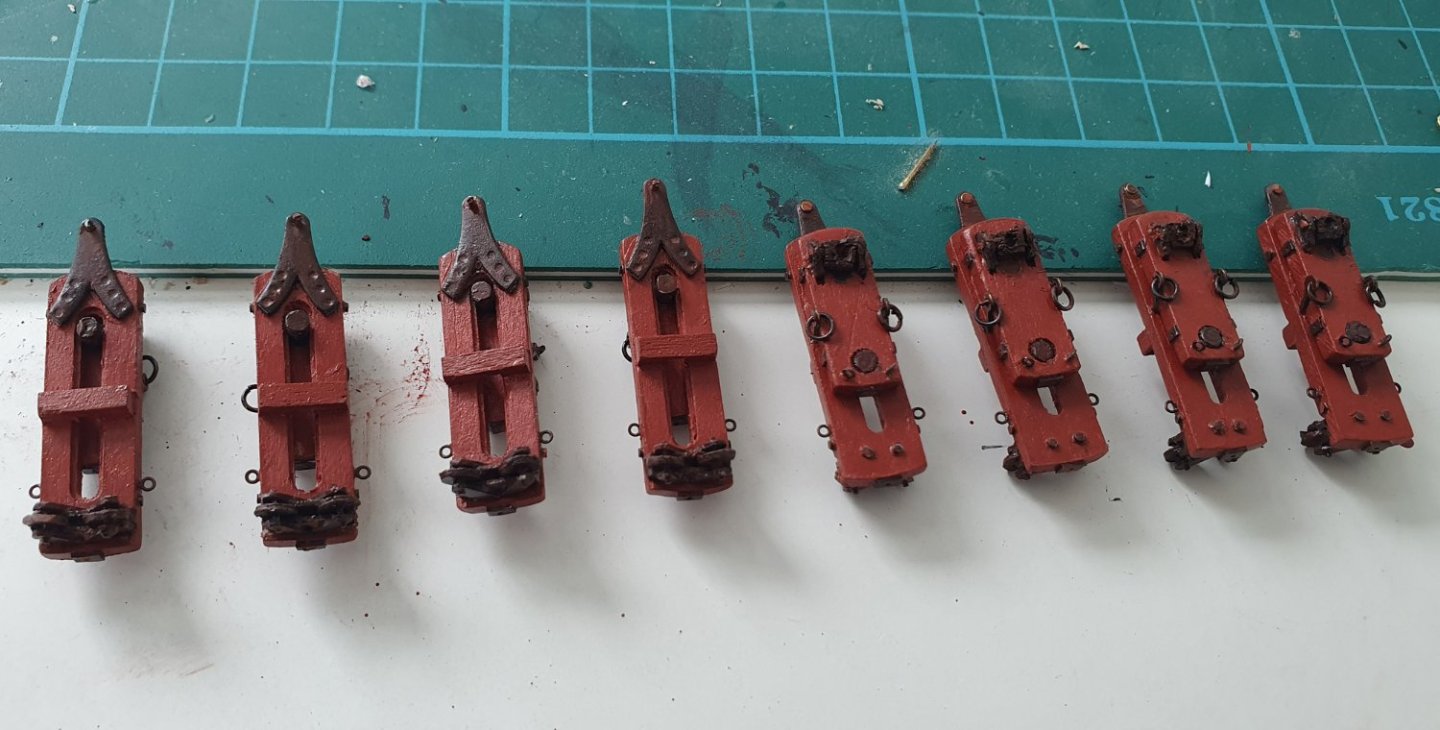
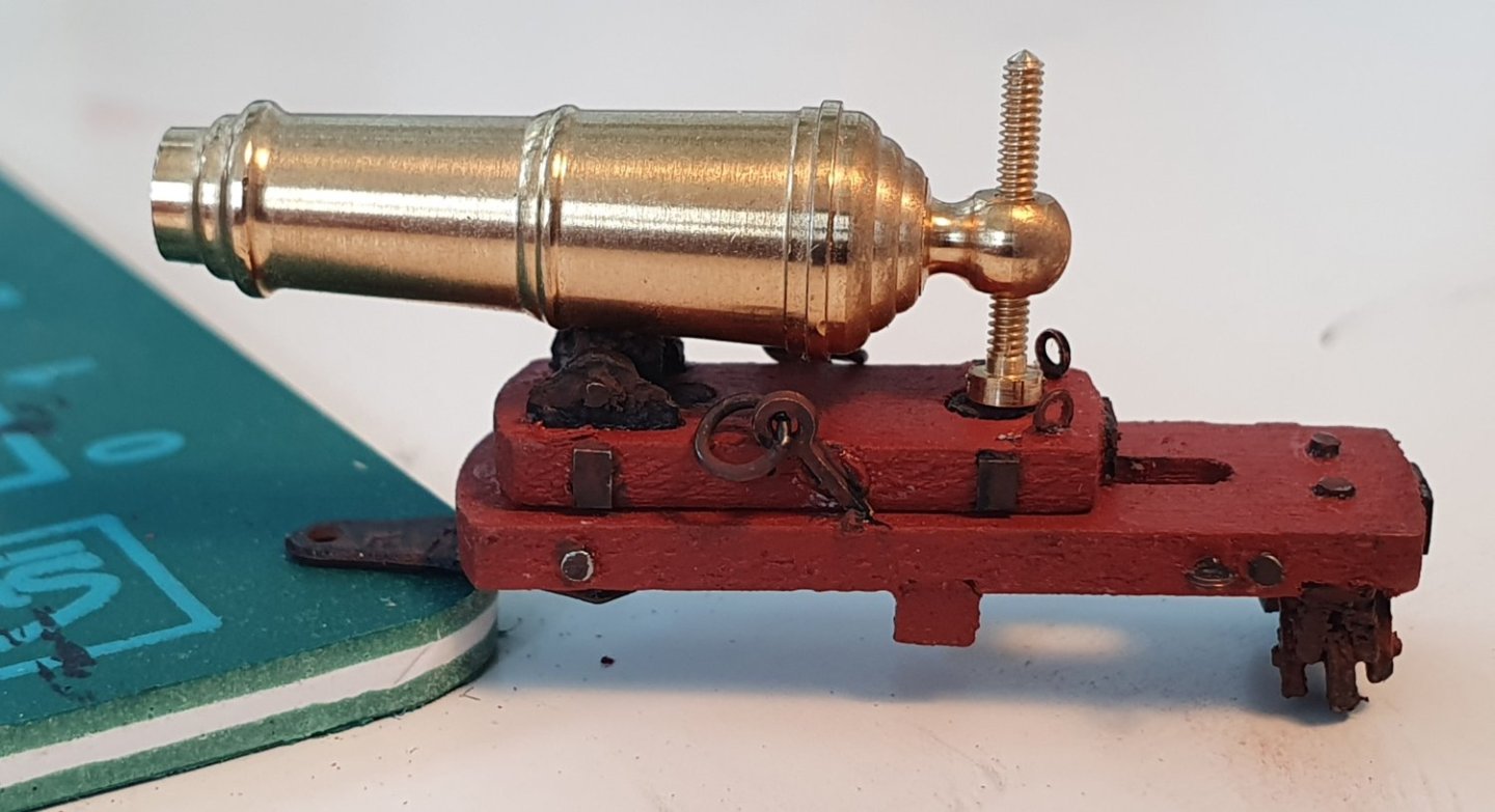
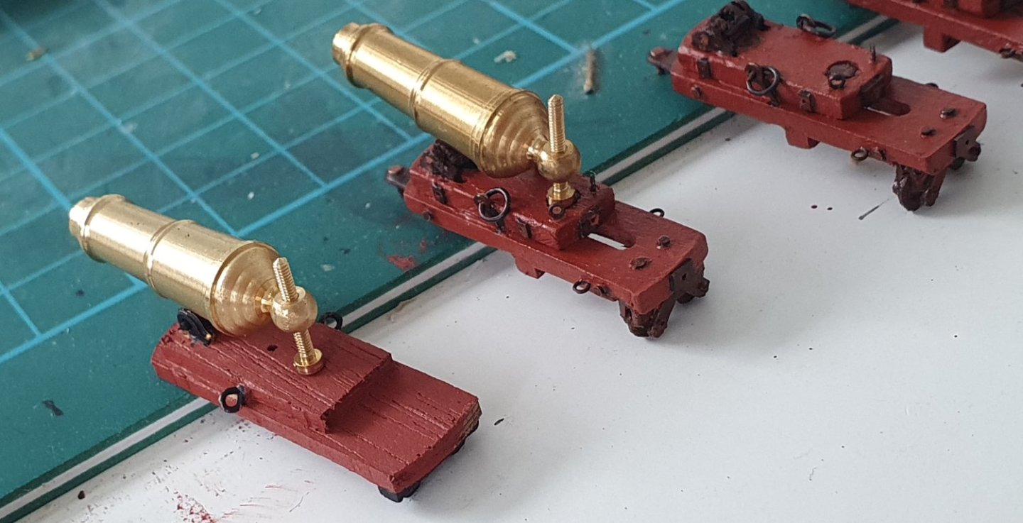
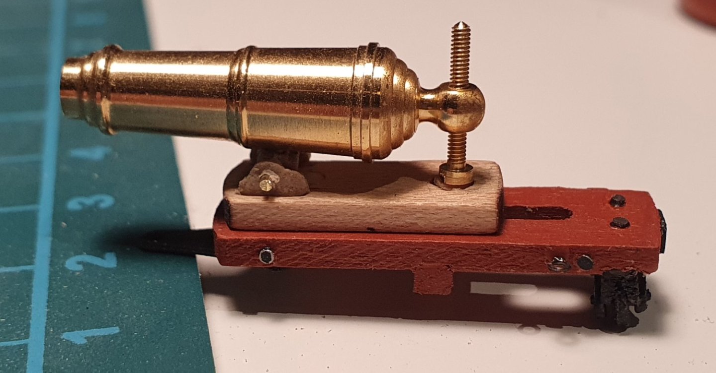
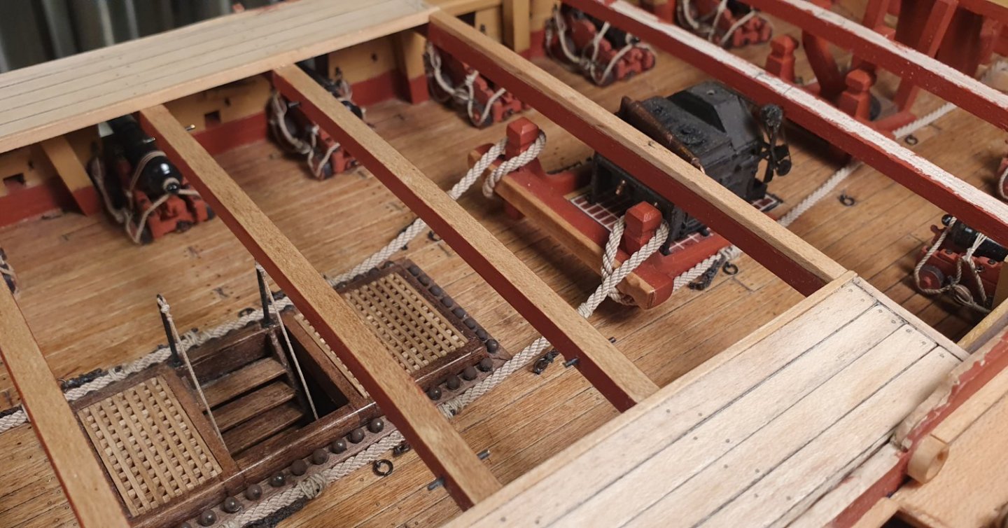
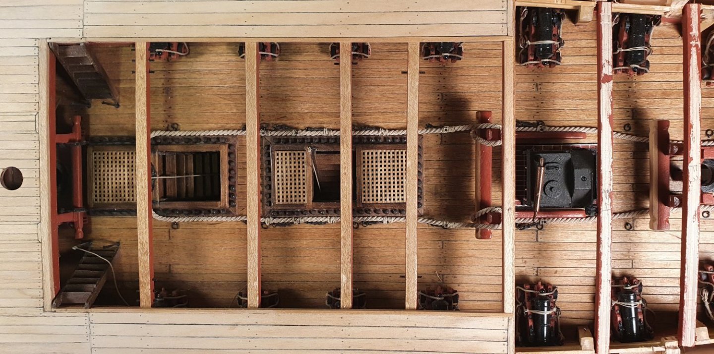
I assembled one of kit supplied 9lb guns to see what I was dealing with. They are probably better than the carronades but they have some issues. The side brackets are too thin 1.5mm vs 2mm shown in the AOTSD drawings. The wood has a very pronounced grain and it is ply so has an unfortunate edge look. The axletrees are a bit thin, lack detail and the transom is missing. Time some scratch building I guess. Earlier on in this build log I produced 3D printed gun carriages for the 18lb guns. I was not that pleased with the finish so for the 9lb guns, which are more visible on the upper decks, I thought I might try a hybrid approach where I would 3D print the axles, wheels and other bits and pieces that are not that visible but then use timber for the side brackets. It is a lot more time consuming but I am happier with the result. To begin with I cut out timber blanks from some 2mm thick maple. I found out later that this maple was not the best quality and I had a hard time maintaining the edges which tended to splinter. I had already cut out the 40 blanks so I persevered in the hope that it would just look like the canons had seen a lot of action. I printed out a template so I could locate all of the holes and cut outs. I built one as a prototype to see how everything went together which brought about a couple of modifications. The prototype was a bit wonky so I printed out a jig to help me align the parts more accurately. I had made the bracket bolts from some small brass nails but they were a bit to prominent so I went forward using 0.8mm diameter black annealed wire filed down almost flush. For all of the gun tackle loops I experimented with the various PE ringbolts from HiS Models and others however it was a case of them being slightly too small or slightly too large so I had to resort to 0.3mm diameter black annealed wire wrapped around a 0.8mm rod. The two ends of the wire are fed through a hole drilled into a scrap piece of wood and twisted together. A bit of a fudge but the best I could come up with. The stool bed and quoin were 3d printed. After what seemed like an endless number of experiments and an afternoon wandering around the dollar store to see if there was something I could repurpose I ended up making the quoin handles by shaping the pointy end of a toothpick using the lathe and some small files. No two are the same but it is a part barely visible to the naked eye. I used the kit supplied canon barrels as they are good quality however they use a 1.5mm diameter trunnion. The drawings in the AOTSD indicate that this should scale to a diameter of 1.7mm. I could only find 1.5mm diameter and 1.8mm diameter brass rod. I went for the larger size as the smaller diameter looked a bit tentative. I had to drill out all of the barrels but I think the larger size sits in the carriages more confidently. I guess I could have lathed the 1.8mm diameter rod down to a 1.7mm diameter but that seemed like a step too far. The capsquare was the kit supplied version with an HiS PE eyebolt and a piece of 0.4mm diameter wire for the capsquare eyebolt and joint bolt. I had a go at turning the wheels from birch dowel but soon tired of that and resorted to the 3d printed versions to maintain consistency. The bed bolt and transom bolt were formed using 0.95mm diameter black annealed wire straightened by holding either end in a pair of pliers and pulling until you can feel it beginning to stretch. It was quite a tedious production line to get all 10 finished but with some good tunes in the background the time flew by. A spot of paint and the carriages were mostly finished. Just have to paint the barrels which are sitting in the queue behind the carronades. They look a bit gruesome in macro mode but luckily my eyesight is poor so I do not see them that way in real life. I need to get on finishing up all of the bulwark fittings and rails though. Not looking forward to that as I can foresee some problematic geometry arising from earlier missteps.


-
Thanks for the encouraging words Jason. I am very pleased to see that you have restarted your Jason build log. I look forward to the upcoming posts. Regards, David
-
Thanks for the kind words Cisco. My uncharitable view probably comes from spending too much time in their company.
-
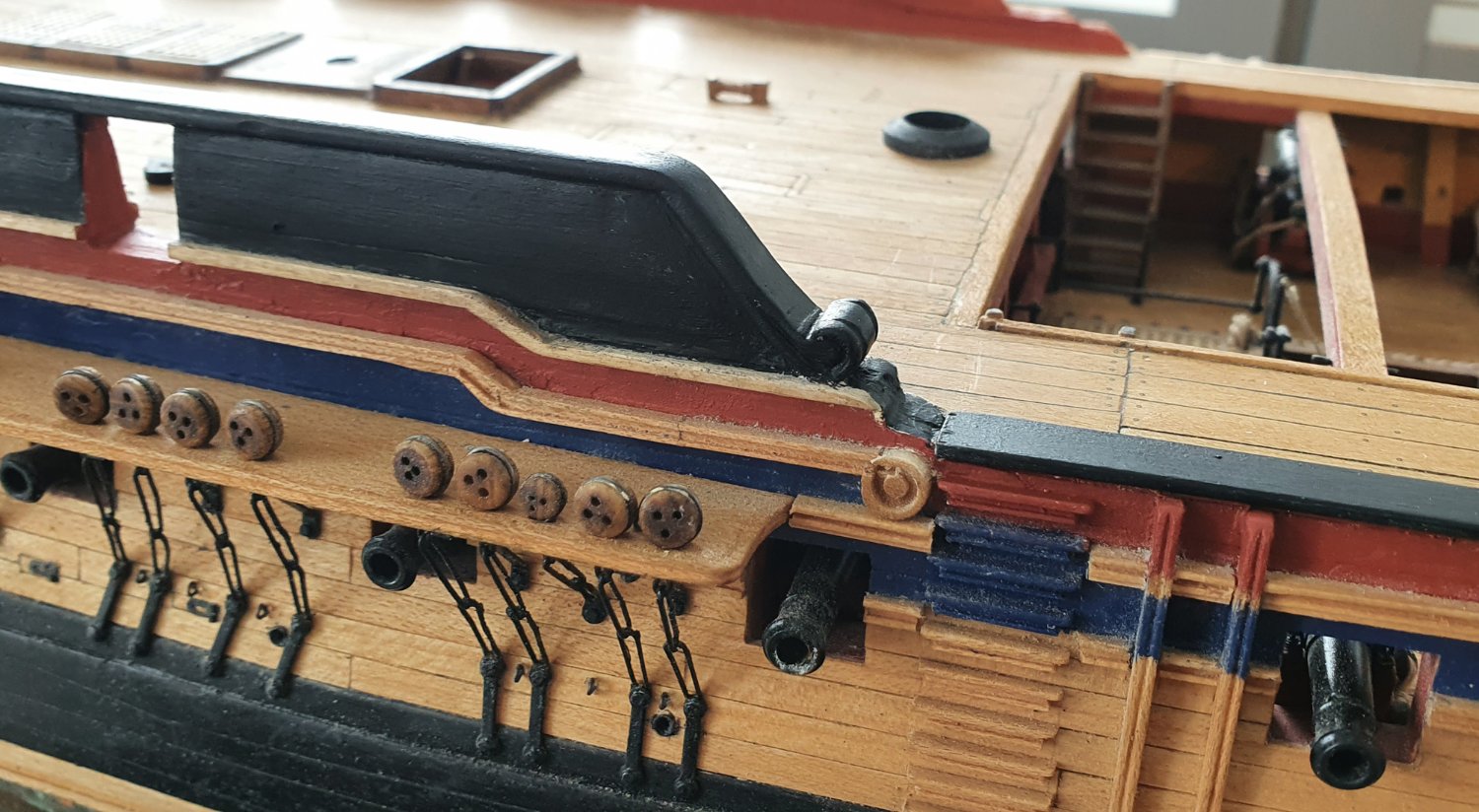
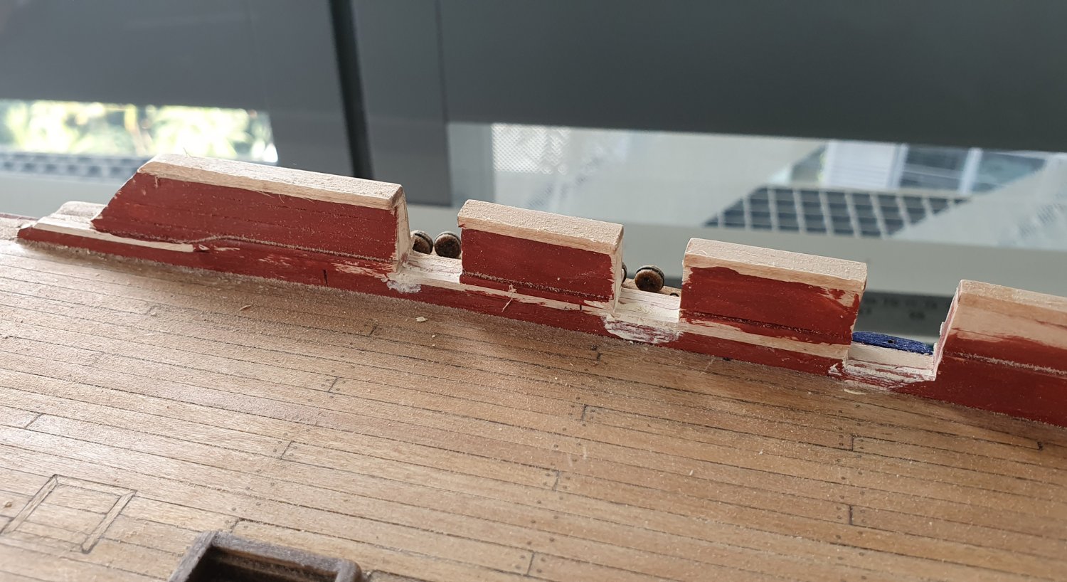
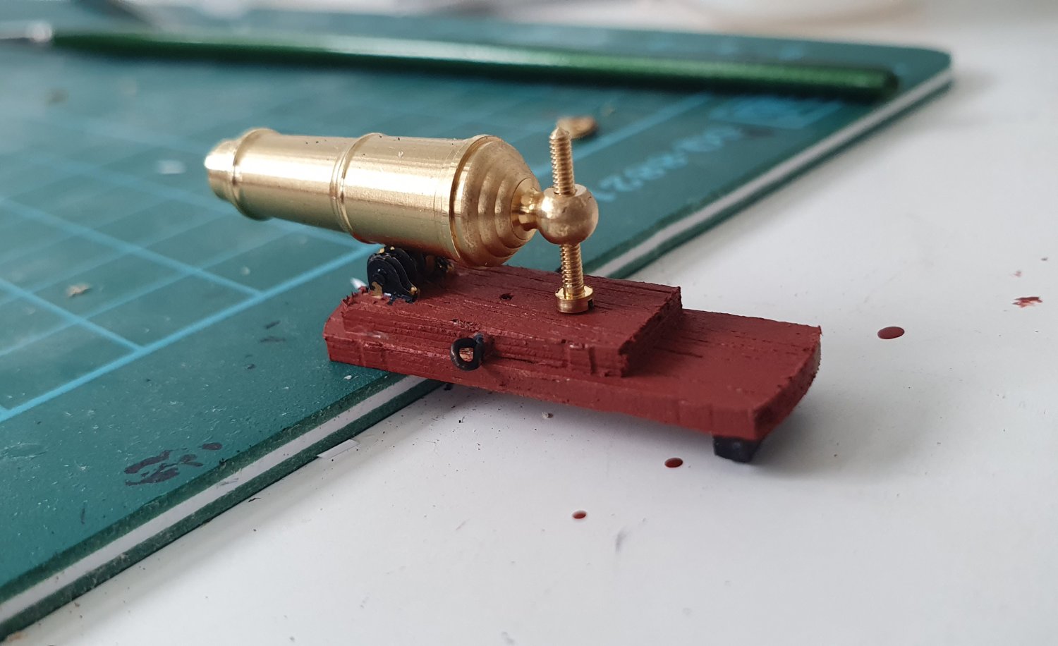
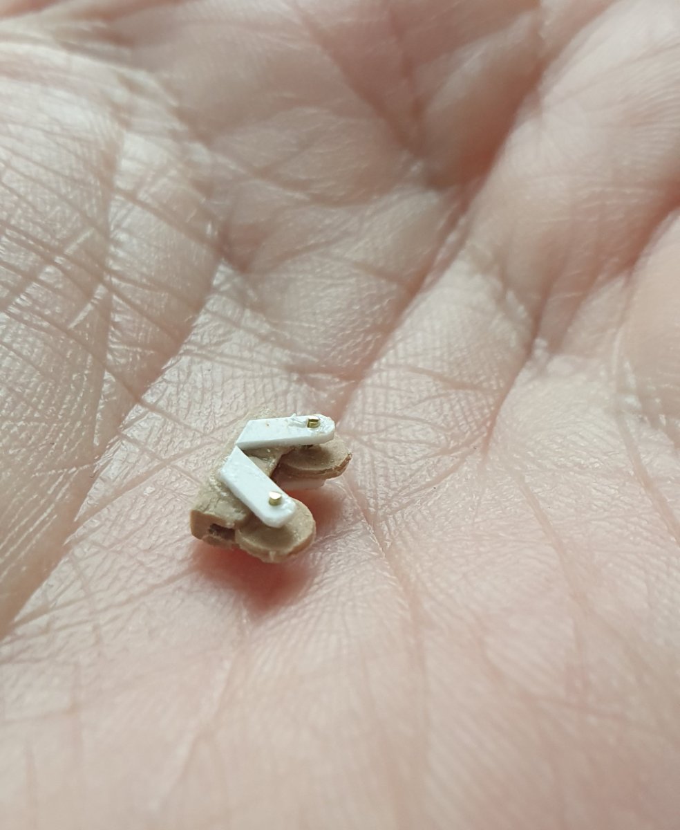
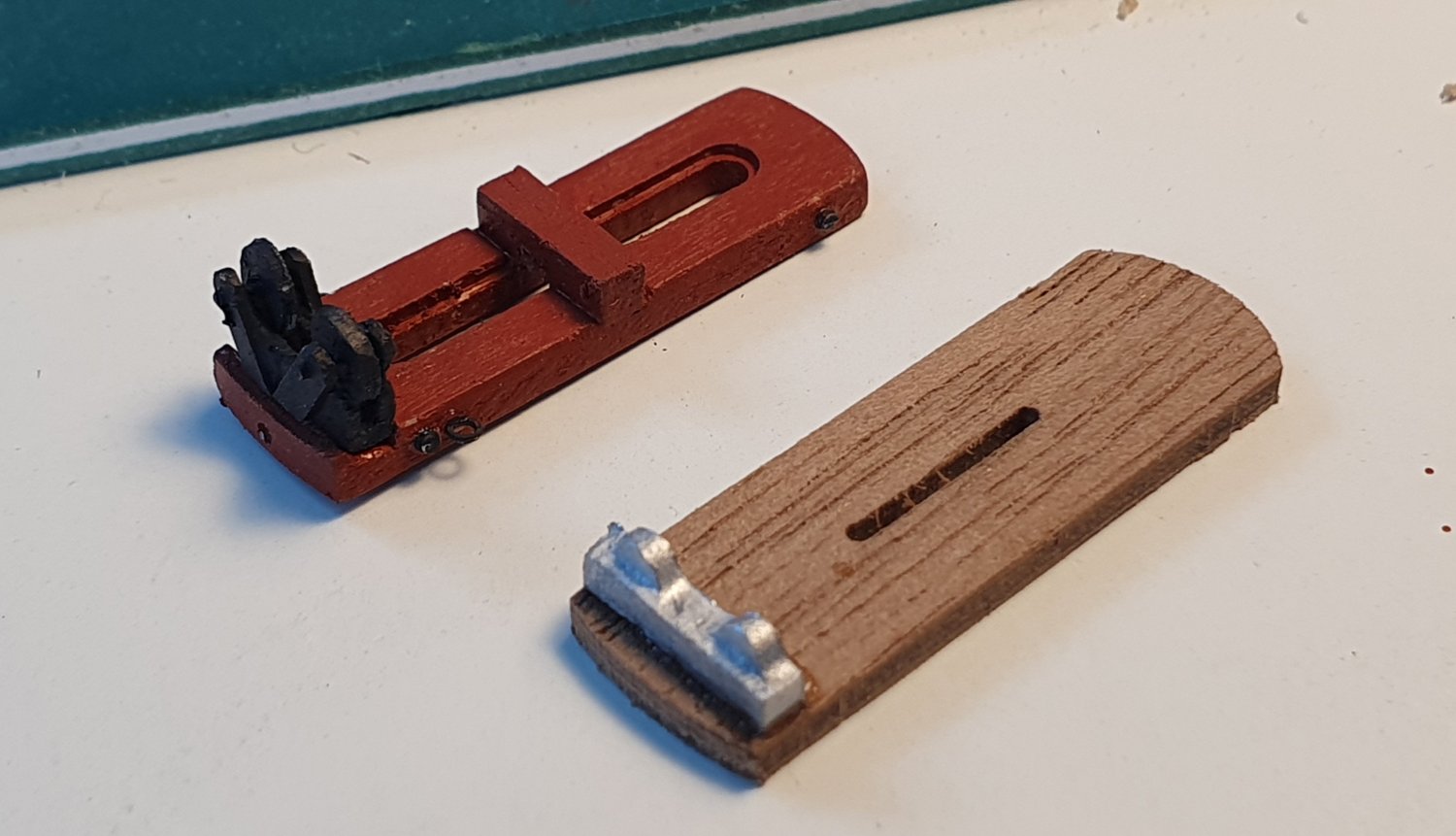
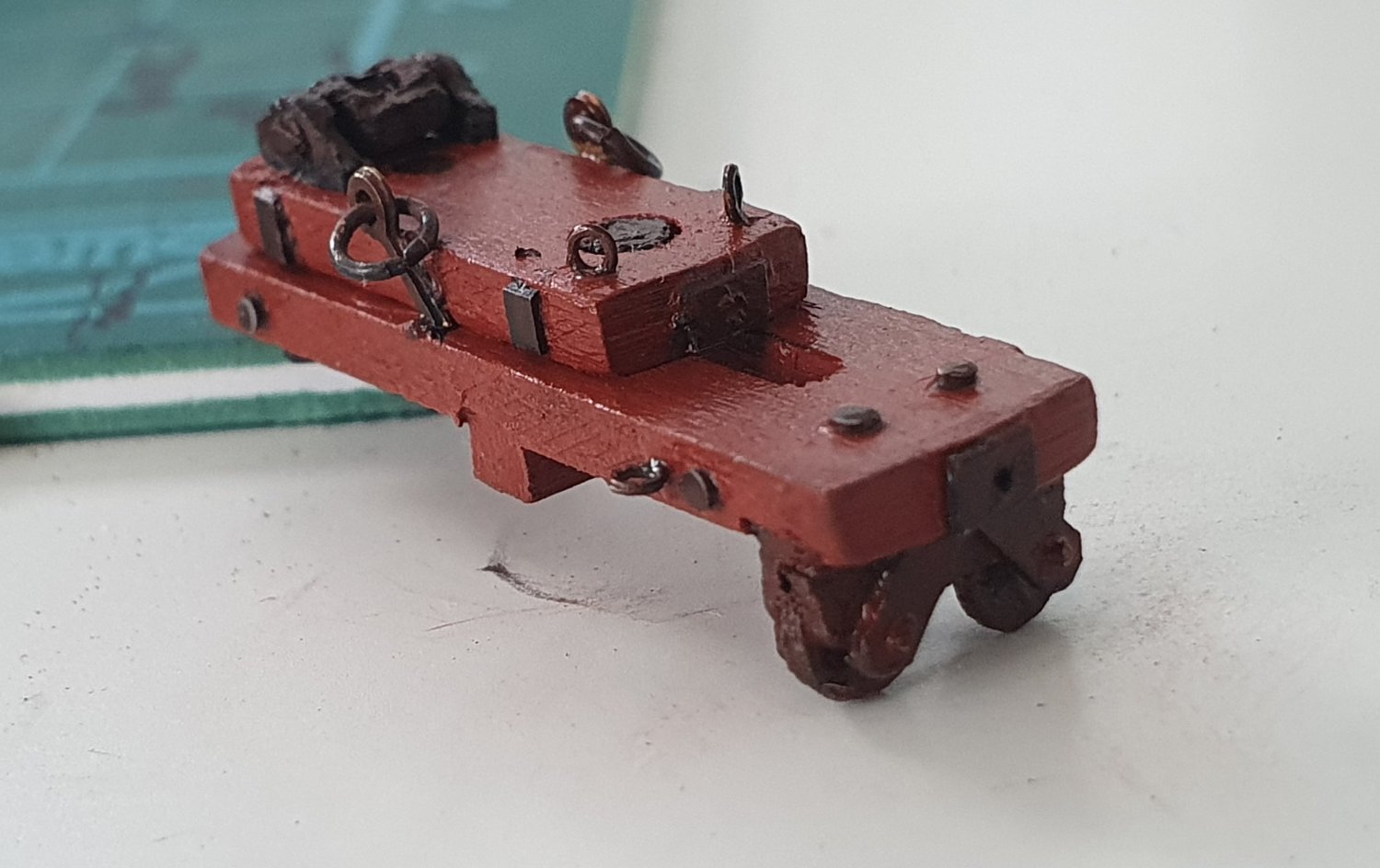
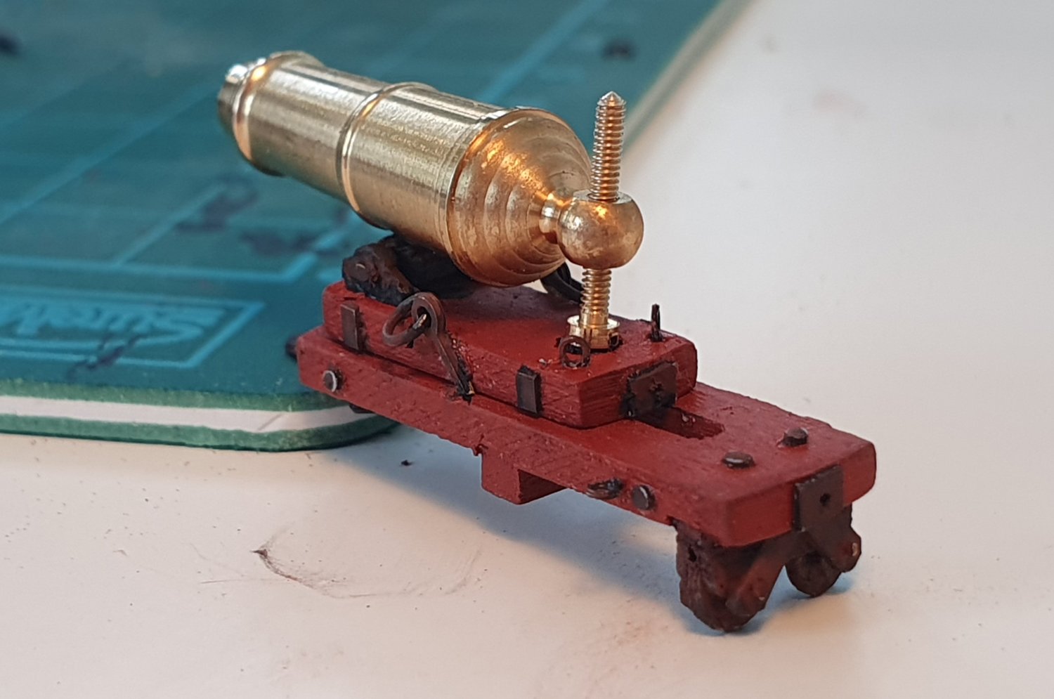
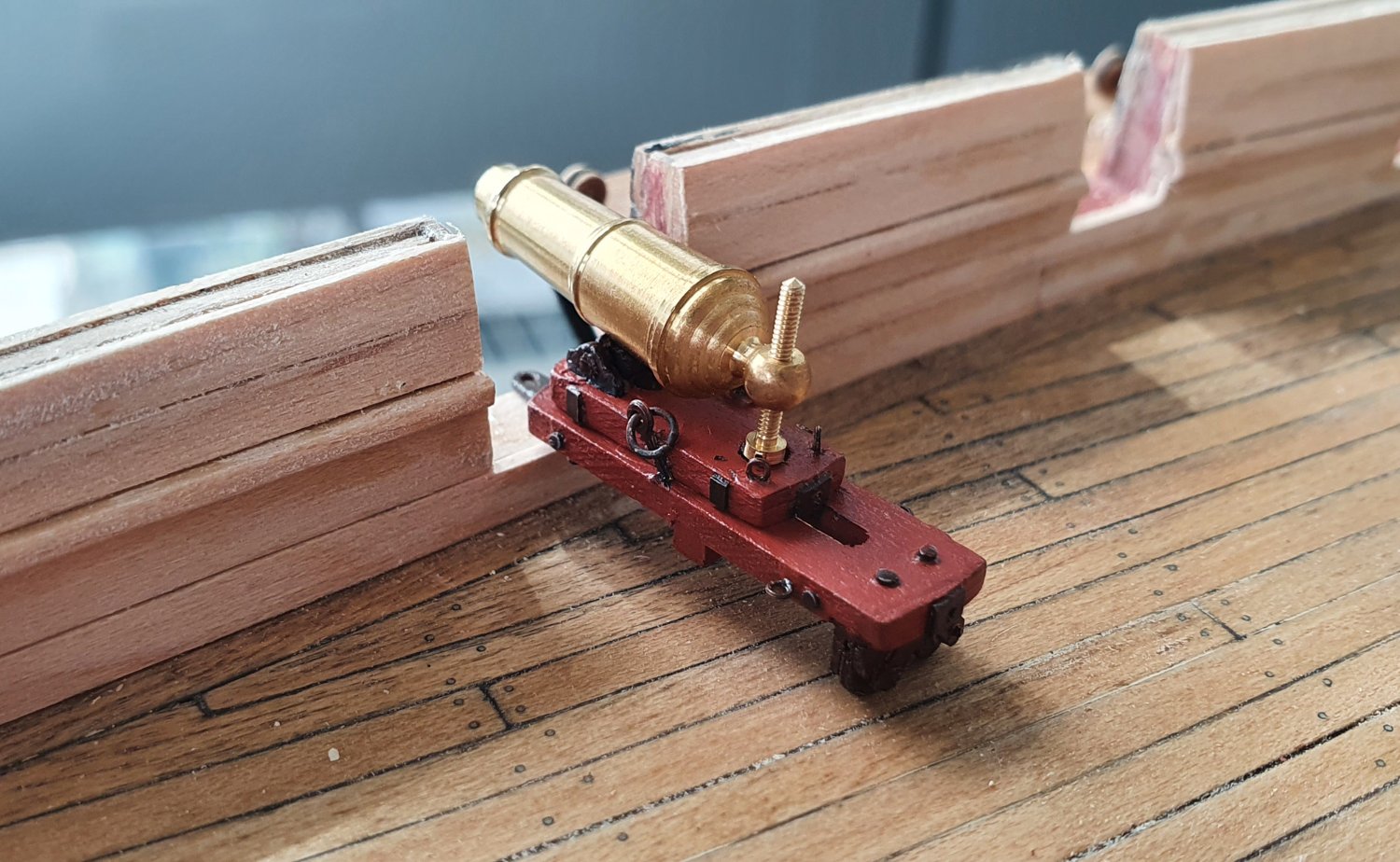
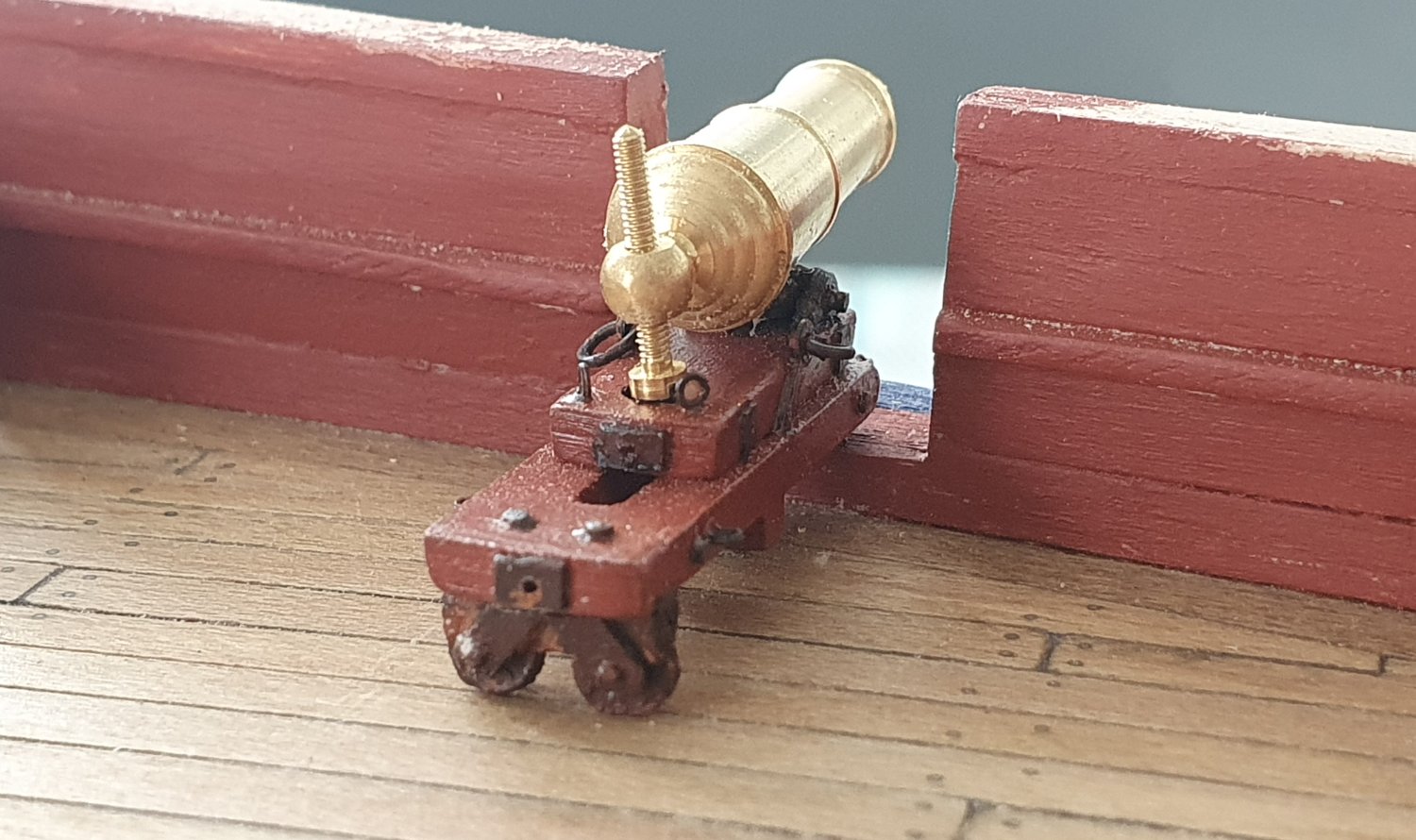
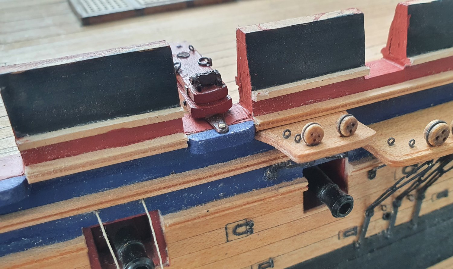
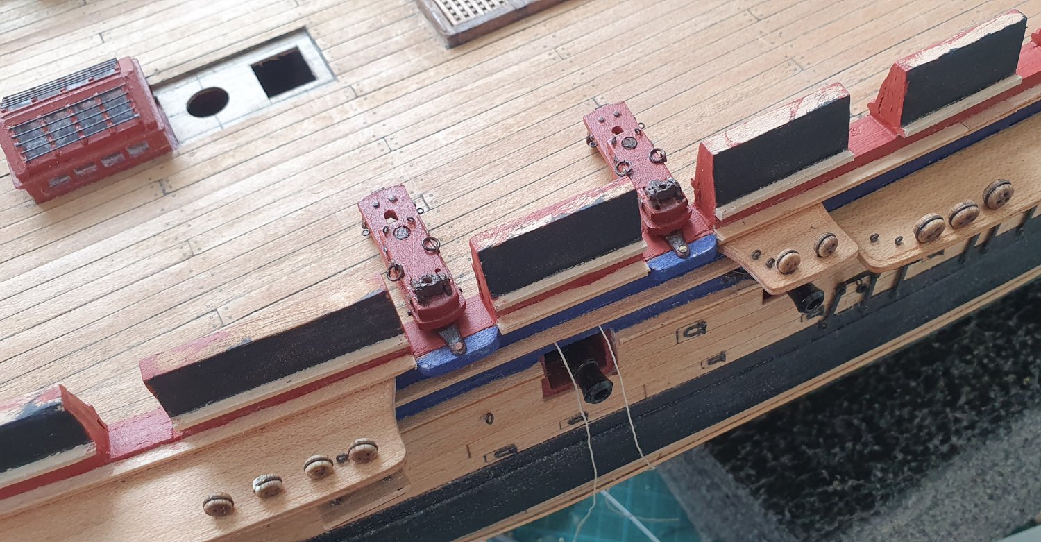
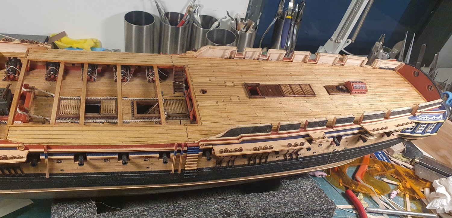
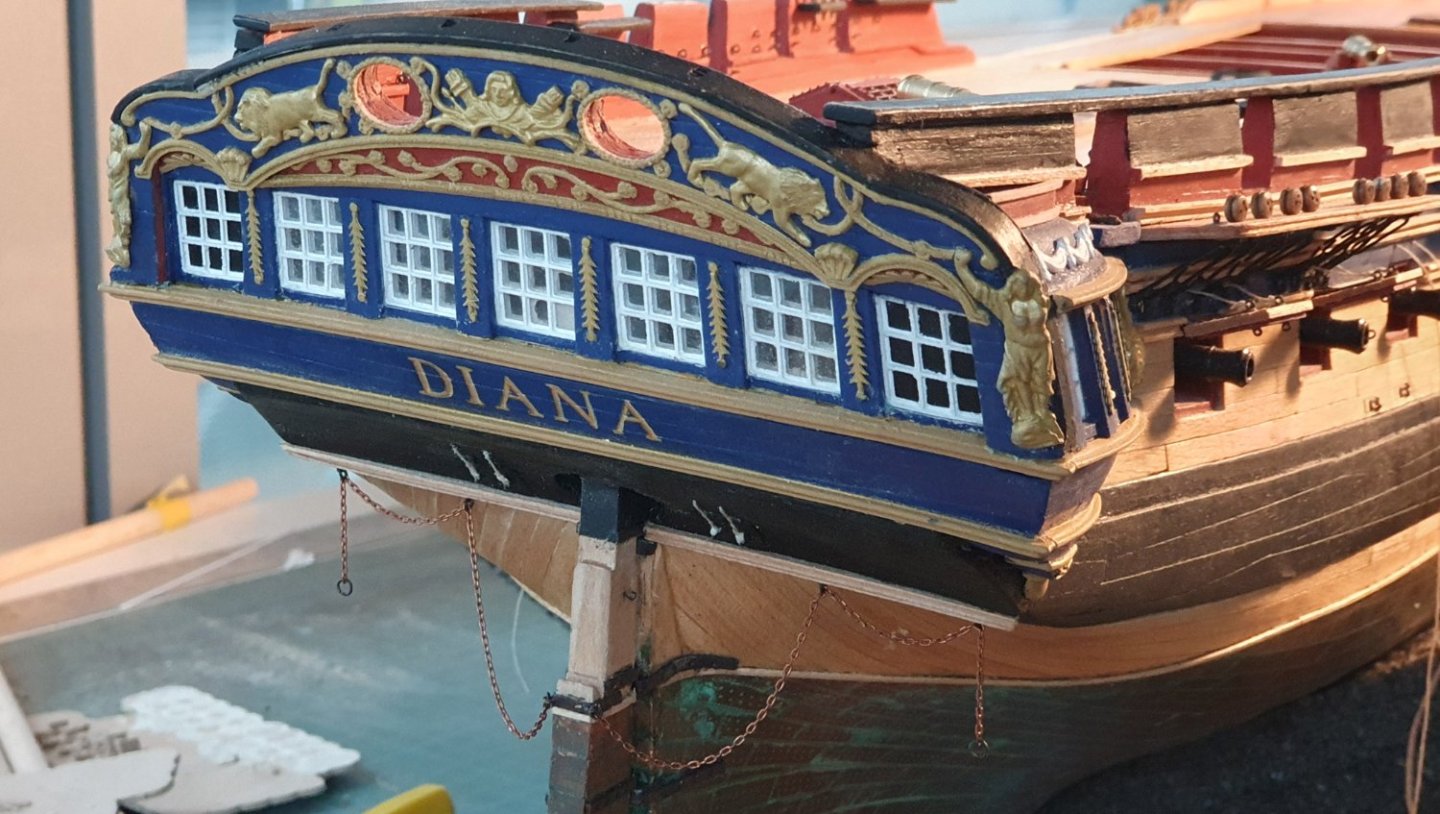
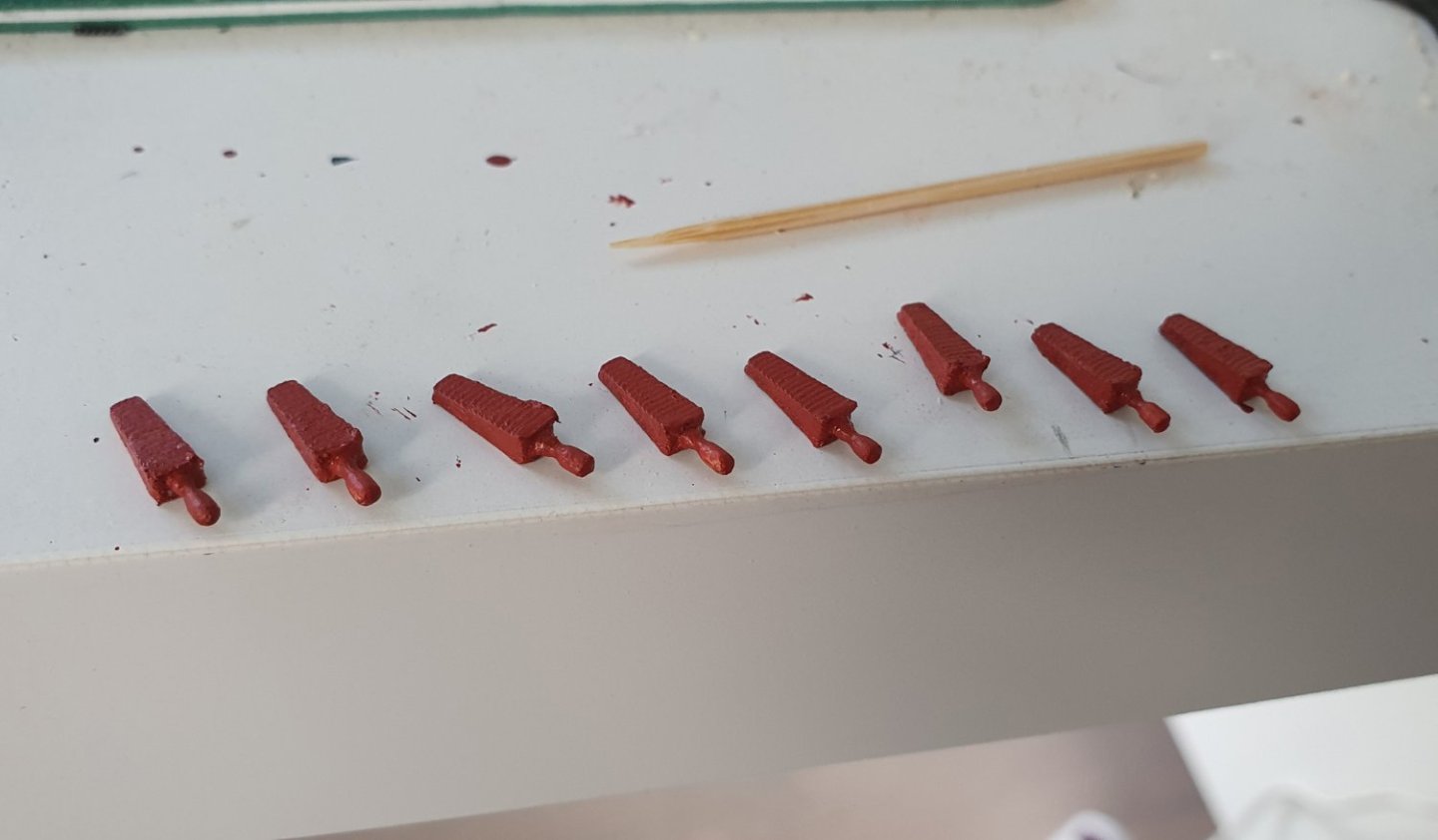
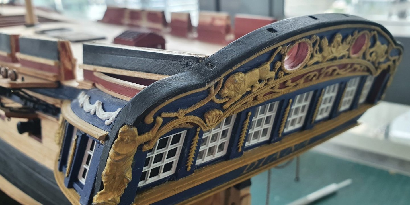
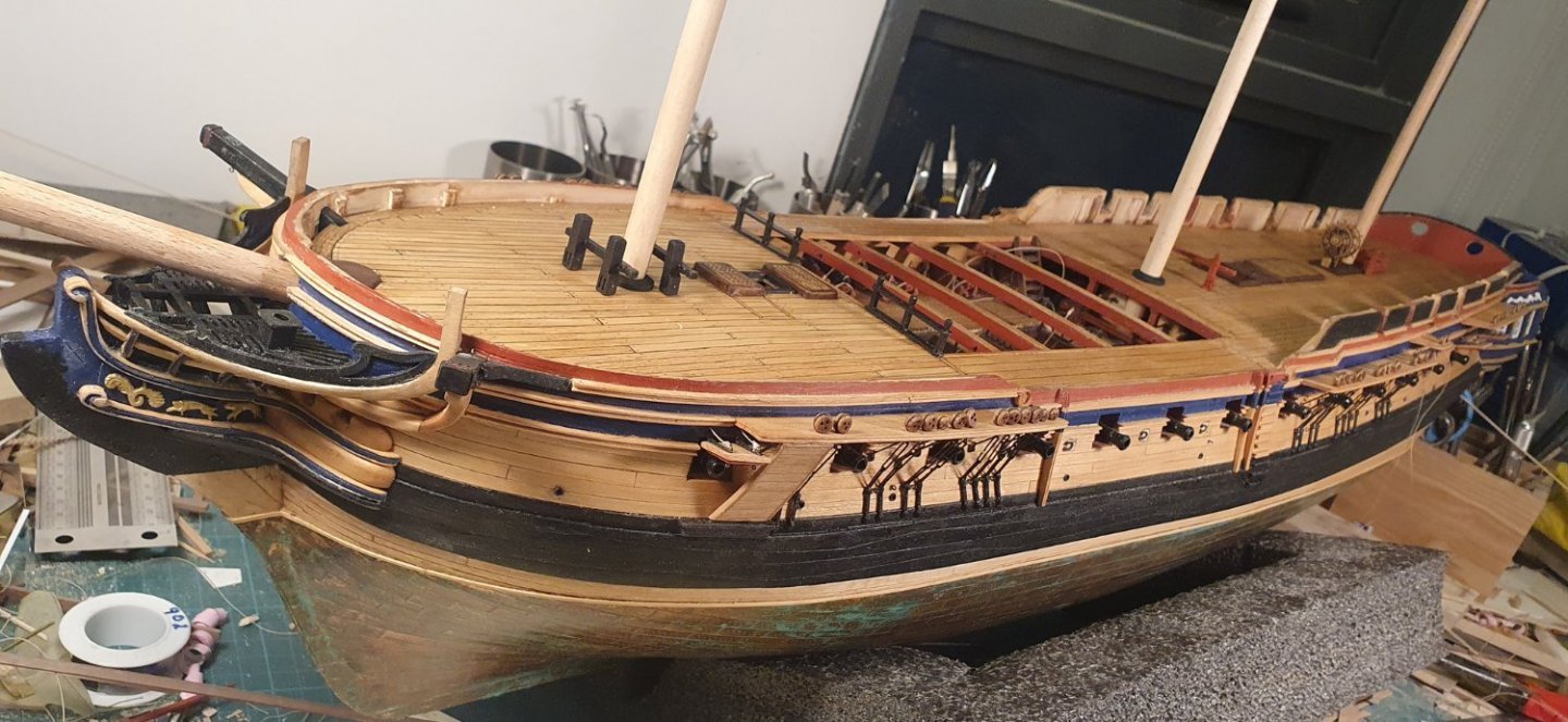
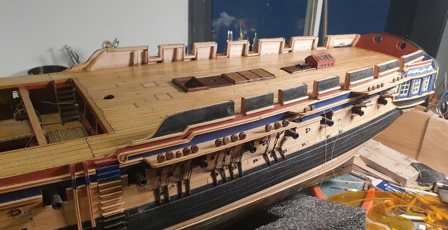
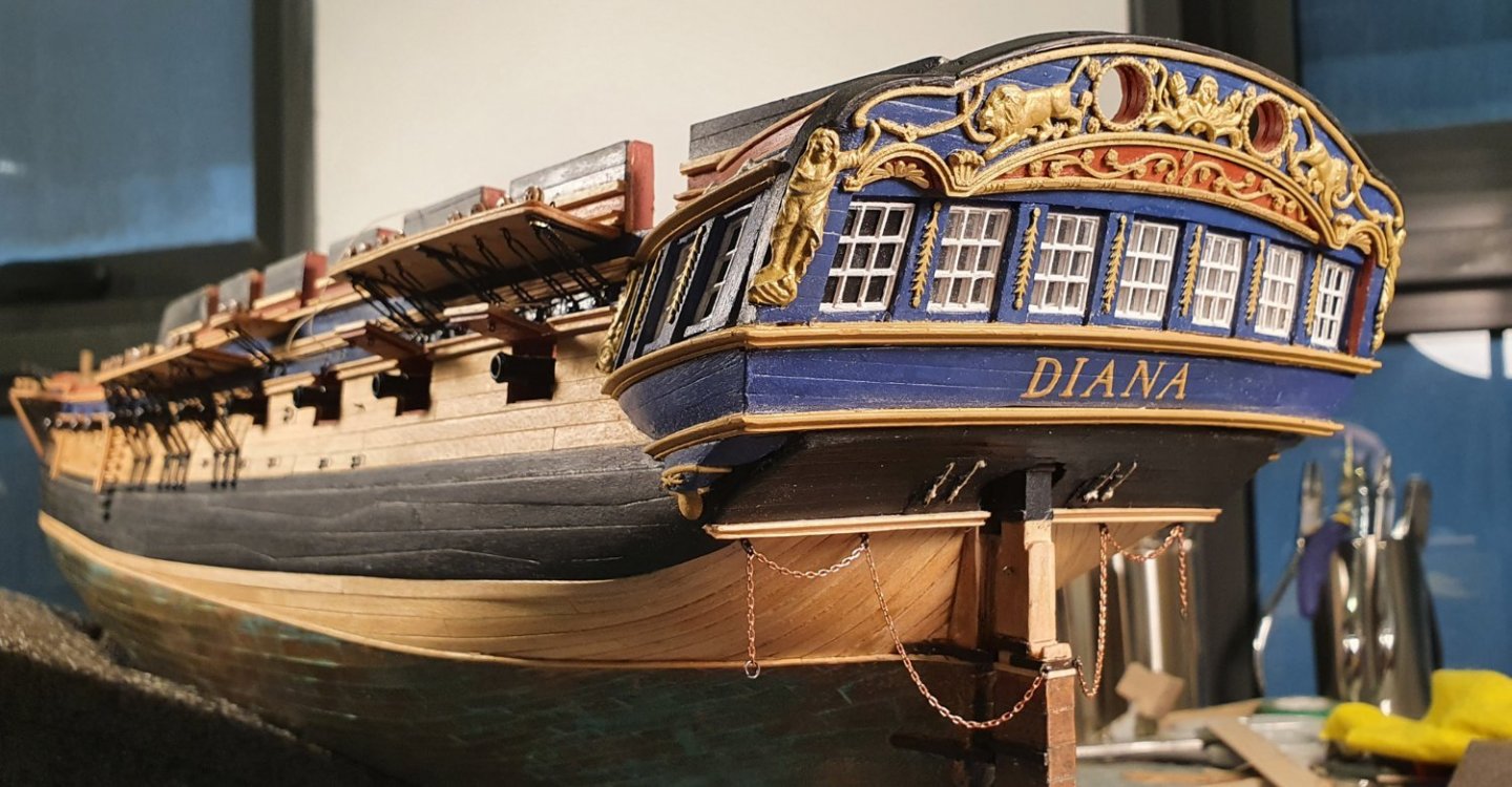
Work on the Diana has ground to a halt these past four months as I have been moving apartments. The move has happened so I will now have no excuse for lack of progress other than laziness. I did fret about moving the Diana and began to dream up designs for temporary cradles that would form a sturdy travelling case to avoid damage during the journey. In the end I just bunged the model onto the back seat of the car, tried to avoid the worst of the potholes and slowed down for the speed humps. It arrived with nary a scratch. My new workspace is an improvement on the previous layout. It is larger and has a lot more natural light to aid my feeble eyes. To get going again I had a go at planking the inner bulwarks which turned out to be a bit of a disaster to be sure. I knew from calculating the size of the frames and thickness of the planking that it would end up too thick but I carried on regardless thinking that if I used enough glue and clamped the planking very hard it would somehow miraculously resolve itself but funnily enough it didn't. Once I had completed half the starboard side I paused to measure the result and the width at the top was 7.5mm compared to the target 4.5mm. With overhangs this would result in the width of the rough tree rail of 9mm rather than the 6mm as indicated in the AOTSD drawings. It would have been too much of an anomaly to live with so all of the work had to be stripped off and I then went at the existing framework with the dremel and a sanding drum. Not always the best course of action to be using handheld power tools next to finished areas. It ended up a bit rough and ready but I was able to reduce the thickness at the top of the bulwark to around 5mm which would give me a 6.5mm rough tree rail which is close enough for my purposes. Now that I have more or less completed these bulwarks I realise that I should have gone about it in a different way. Studying the AOTSD and NMM drawings it is quite evident that it was built with open rails which were closed in at a later date. This is the way I should have built the model but instead I carried the framework up to the rough tree rail and then glued a false plansheer on either side. Lessons learnt I guess. At one point I did consider swapping out the sanding drum for a cut off disc in order to shear the upper bulwarks off to just below the level of the plansheer but I stepped away from the model at that point and went out for a coffee to wait until the madness passed. Once that I completed that exercise I realised that I would have to bite the bullet and increase the height if the bulwarks. This all harks back to the whole debacle relating to the height of the quarter galleries discussed earlier on in this log. I am now paying for my lack of action. I just went up another 2.5mm so that they would stick up above the taffarel. I achieved this by gluing a lump of maple onto the top and sanding it flush with the dremel. I lost most of the planking definition but it was the easiest solution if not the most elegant. In hindsight I should have gone down the open rail route as it would have been easier to fudge the geometry. After the bulwark trauma I decided to assemble the carronades as it looked like quite a gentle task. My initial thought was that the kit supplied carronades were well made and would be a piece of cake to throw together but when I mocked one up and then compared it to the drawings in the AOTSD book I realised that they were quite off dimensionally and also lacking in detail. I noticed that some of the other modellers replaced these with the Vanguard versions which look a lot better but I have had no luck with the UK postal service these days so I decided to have a go scratch building them. The supplied barrels, elevating screw and iron plate bracket for the fighting bolt are all accurate and of good quality which meant that I would only have to build the carriage which should hold no terrors. I modelled all of the parts in CAD with a thought to 3D printing them but my current set up does not produce the required resolution for such small elements so I had to resort to more traditional methods. I was however able to salvage the channel for the truck as well as the wheels. I then used some styrene for the iron plate brackets with 0.5mm brass rod for the axle. They look a bit rough in the macro shots and to be fair they are a quite rough to the naked eye as well. Luckily their location on the underside of the carriage along with their small size means that I am able to get away with it. The carriage was constructed out of some nominal 2.2mm thick maple with the gammoning slot milled out. The trusty sanding drum took care of the final shaping. HiS Models PE eyelets were used for the ringbolts as they were to scale. They look a bit tentative however they are dimensionally accurate. One of the perils of working at 1:64 I guess. The gammoning bolt is made out of 2mm diameter styrene rod painted black with 0.8mm diameter rod forming the bolt heads and some styrene strips used to simulate the cover plates for the sockets. I should have probably used card stock for these as the styrene is a bit thick. The support structure for the barrel was tricky and I went back and forth between the 3d printed parts and supplied PE before deciding on the 3d printed versions just because they sat a bit lower. A spot of paint and the carriages were nearly done. The barrels still have to be painted black which is a problem given that the new apartment has no balcony. I will have to construct some sort of mini paint booth which is another thing to add onto my ever growing task list. Comparing the homemade version to the kit supplied item it would appear that it is a marginal gain for a lot of effort. I decided to go with the mounting for the carronades based on the outside principal. It will seem controversial to some but after a bit of research I am happy with the decision. I constructed the support to take the fighting bolts from a 3mm thick maple sheet. This detail is not shown in the kit drawings and only alluded to in the AOTSD drawings but I based it on diagrams shown in Lavery's books and photographs of historical examples. It necessitated some hacking out of mouldings that I had spent some time installing so I wish I had had the foresight to look ahead to this detail which may have resulted in a neater finish. Next up I think that I will have a go at the 9lbers.


-
Thanks. I really like your Sphinx build. You have managed to achieve just the right amount of patina. I am quite nervous about the rigging stage as I have yet to master basic knot tying.
-
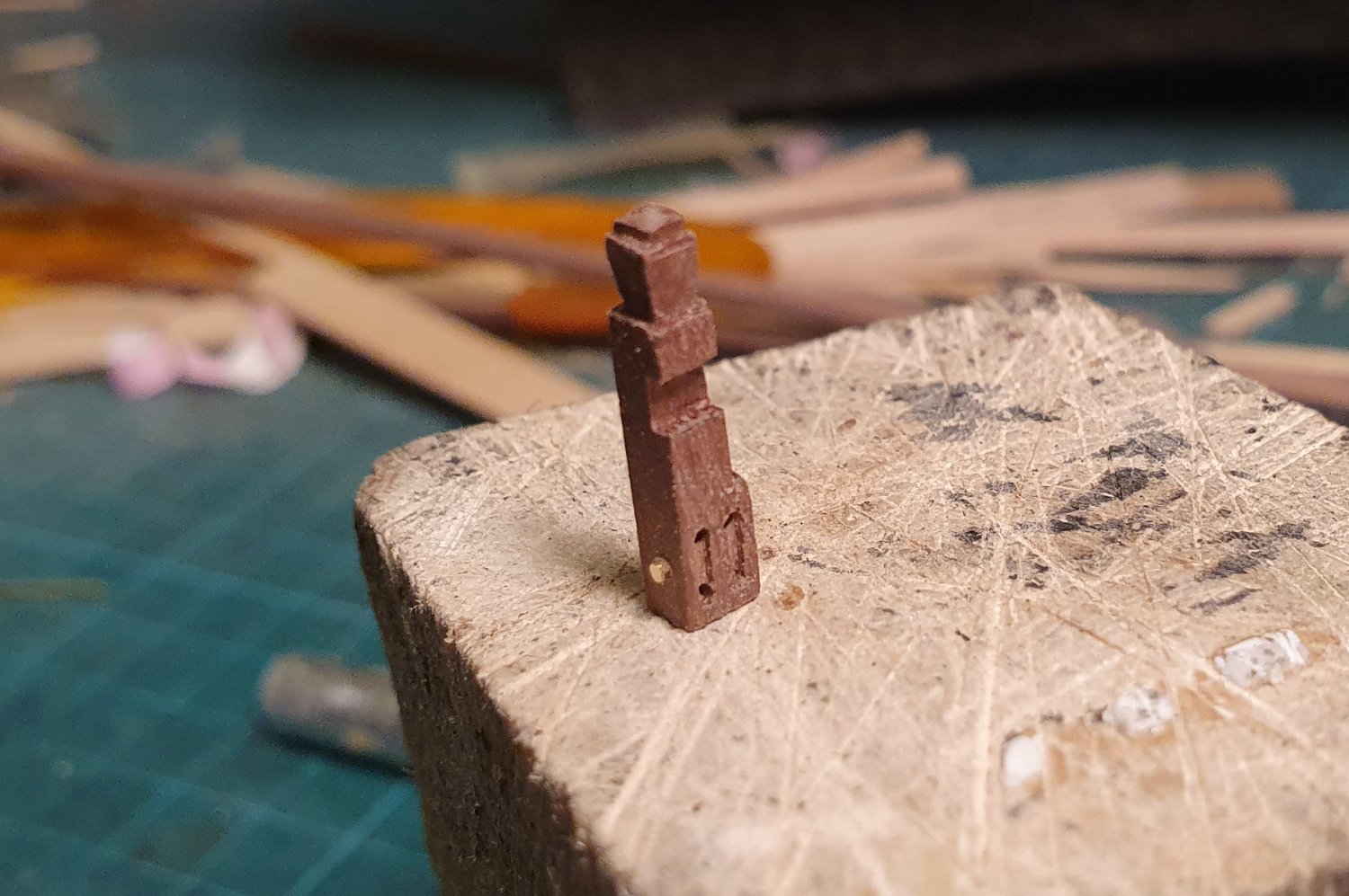
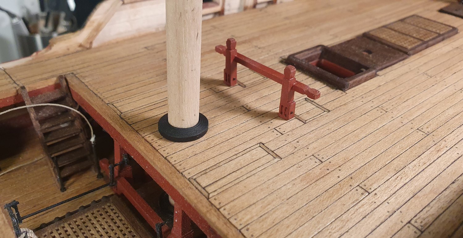
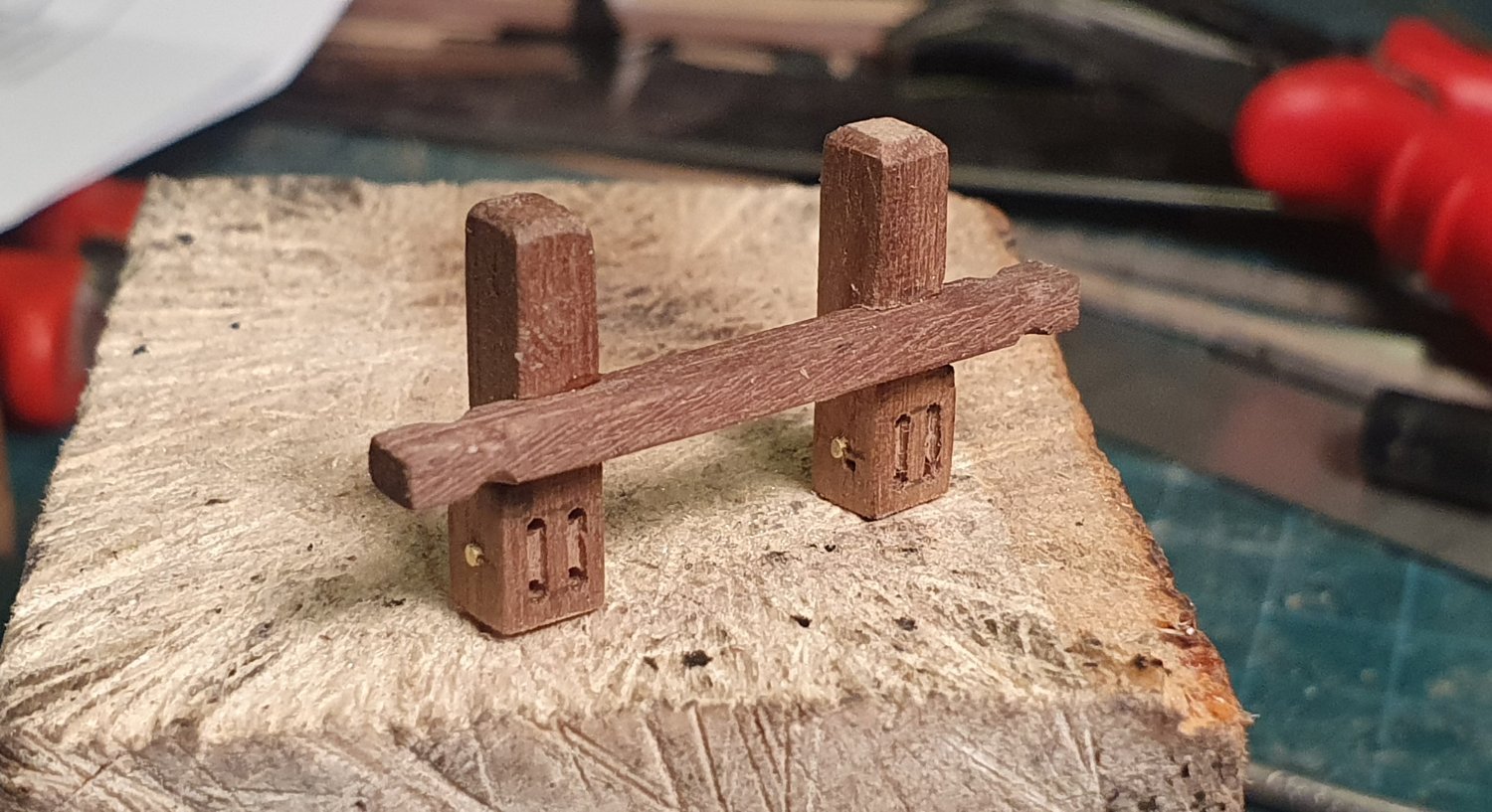
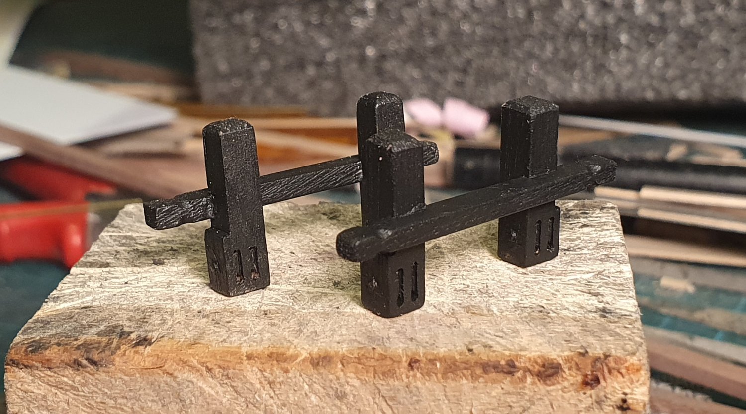
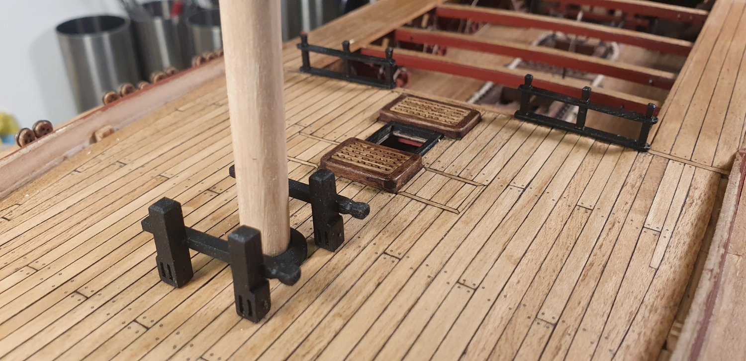
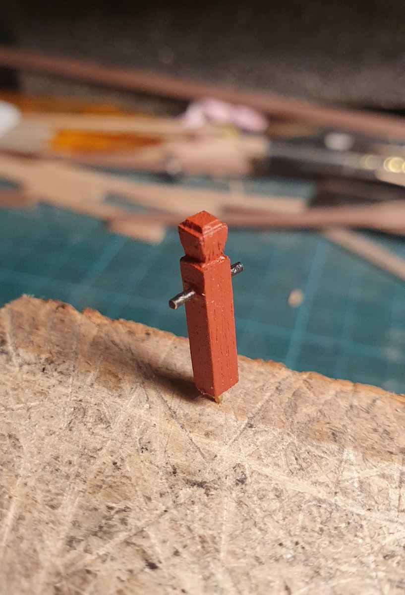
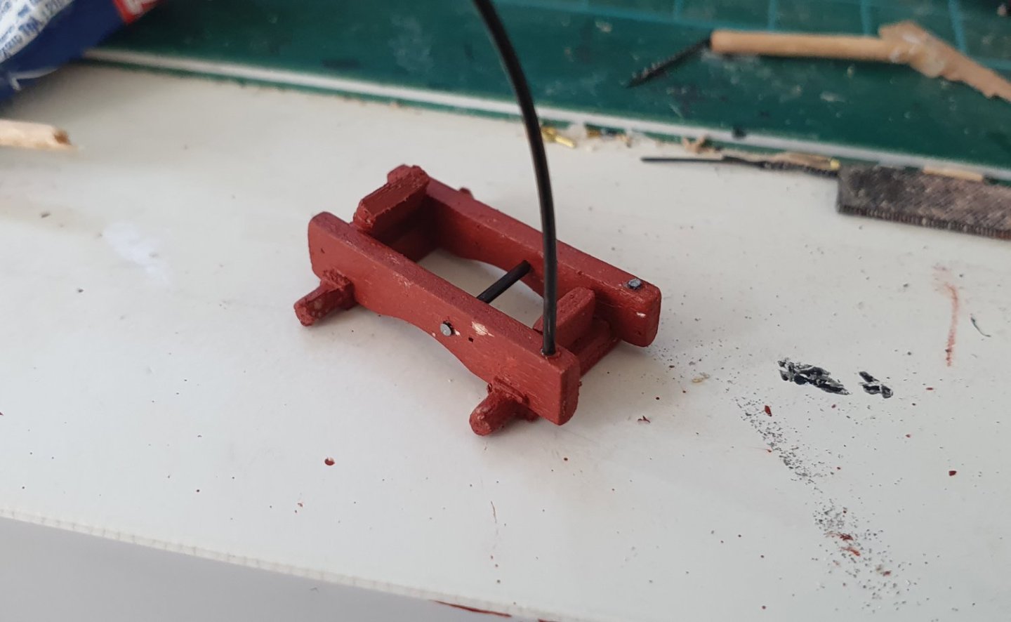
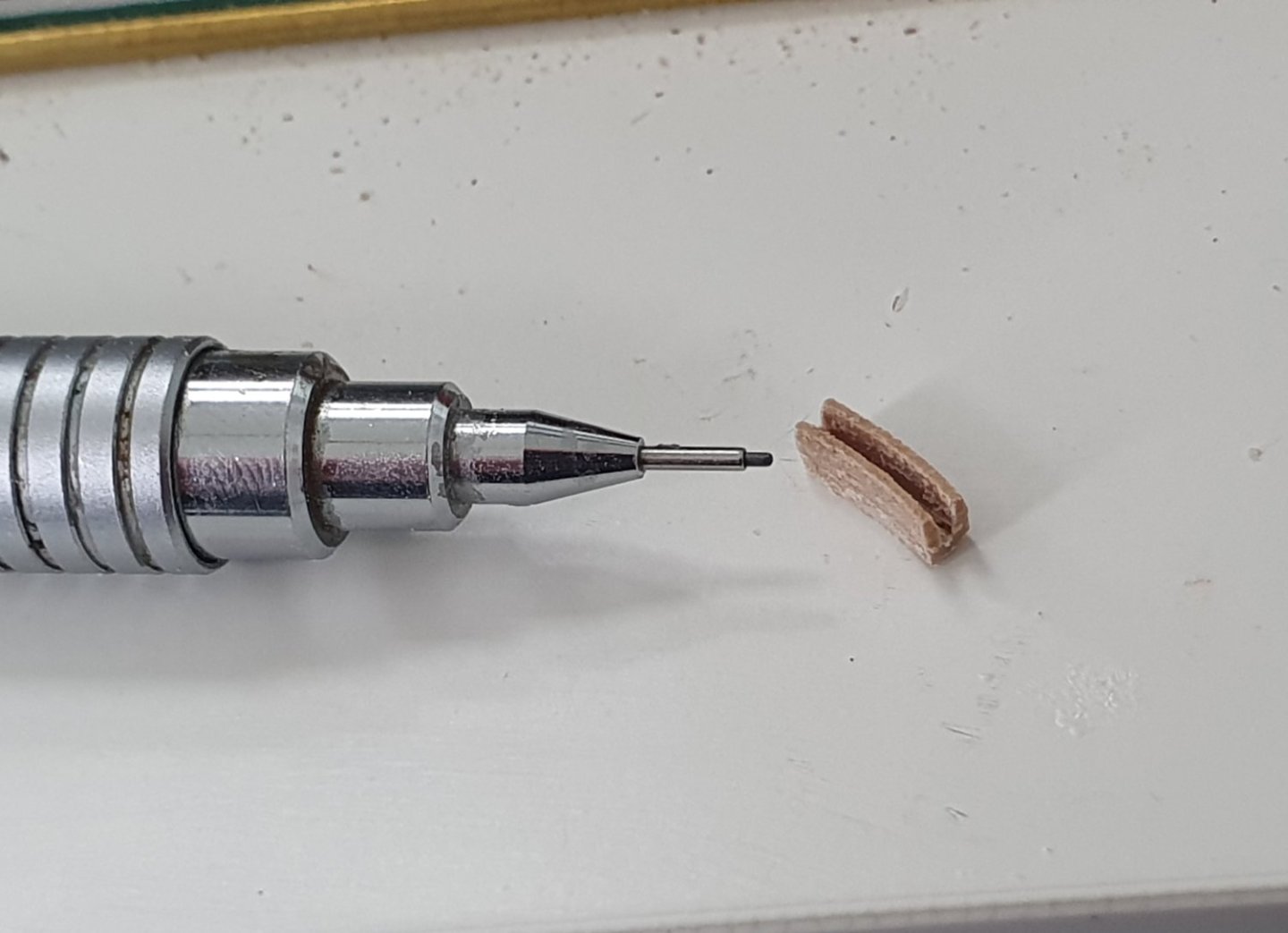
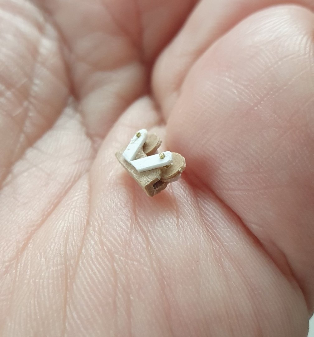
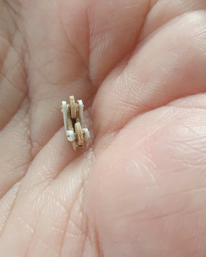
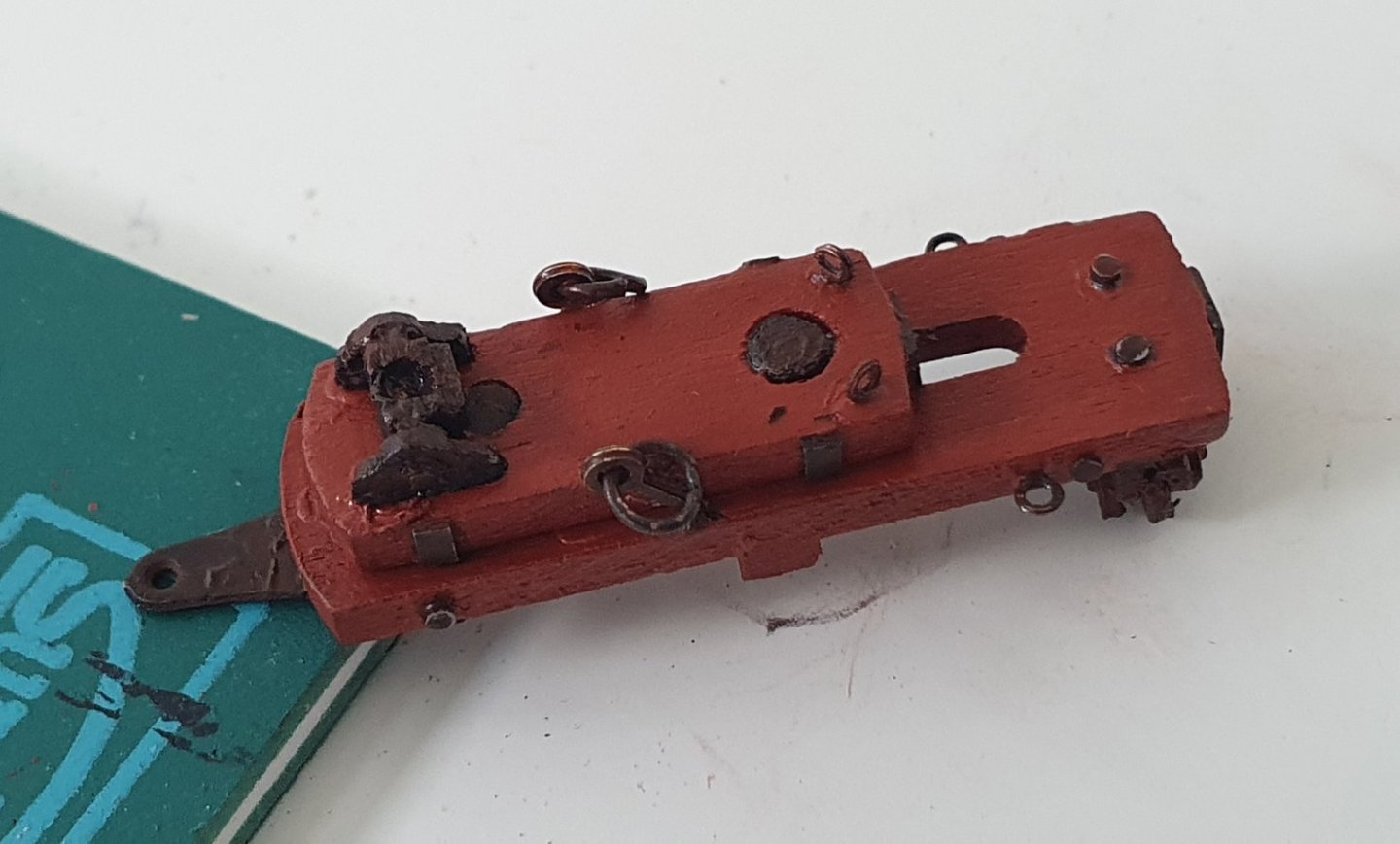
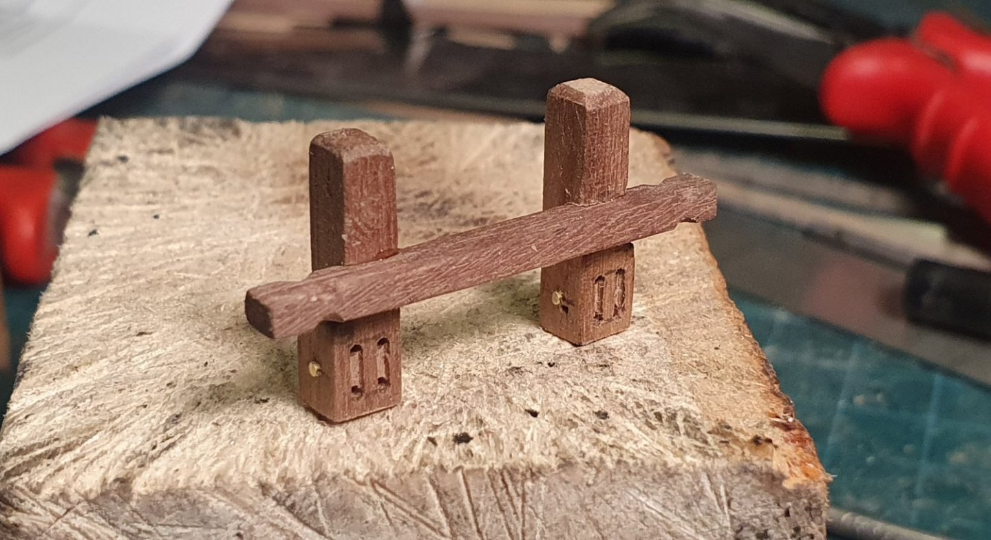
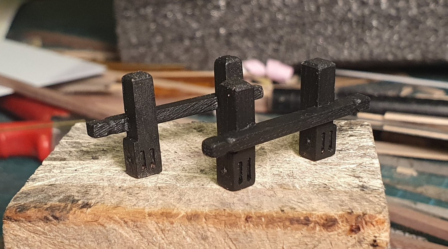
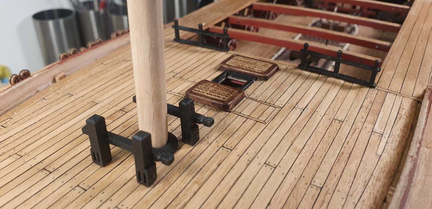
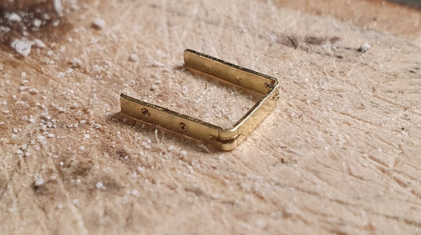
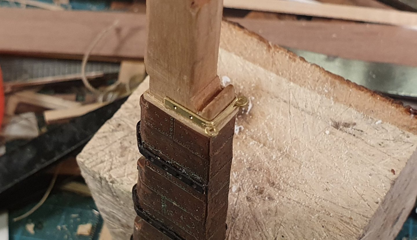
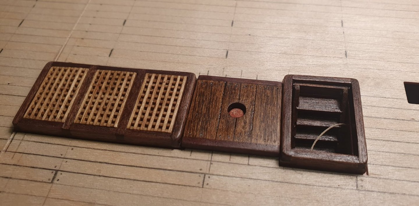
Lots of fiddly bitts to be made. The NMM drawings hint at the location of sheaves in the base of some of these so I ditched the laser cut kit parts and fashioned my own out of some walnut I had lying around. There are quite a lot of steps for such a modest piece. The brace bitts were made out of 3x4mm walnut. The sheaves were milled out using a 0.8mm bit. I probably should have dropped down a size to a 0.6mm diameter bit but I had recently snapped that one and have not yet managed to get a replacement. The sheave bolt was formed out of a 0.8mm diameter brass rod filed down almost flush. The cross member is 2x3mm walnut. Once complete and painted in the admiralty red ochre I thought this assembly looked somewhat delicate. I had dutifully followed the dimensions indicated in the NMM drawings and after checking some contemporary models it would seem that this is more or less correct. The fore jeer bitts and topsail sheet bitts are a bit chunkier with a simpler top detail. I built these before studying the AOTSD belaying drawings and think that these probably should have had triple sheaves at the base. For my purpose I think that I can get away with a double sheave. I painted these black rather than the red ochre of all the other bitts. The black colour is how they are presented in the contemporary models. I do not know why this is so but it must have some significance as it is consistent across all the models I looked at. I fashioned the mast collar for the fore and main masts out of 16mm diameter beech dowel. The kit supplied part was probably fine but they only provided five of these while there are six locations where one might install such an item. I guess their thinking behind this is that the upper deck mizzen base is not visible so this has not been supplied but in a fit of madness I used one of the kit parts in this location which meant that I had to fashion a new one for the quarterdeck. This new one did not match the remaining kit parts so I had to remake those as well. In retrospect I should have just used my homemade one on the upper deck and saved myself the bother of replacing the others. Not the end of the world though as I find using the lathe quite soothing so long as I am not messing around with very small brittle pieces. For the bits next to the companionway I ignored the kit drawings and followed the AOTSD and NMM interpretation where there is no cross piece and just a 0.8mm brass rod to facilitate belaying. Looking at the AOTSD rigging plans I suspect that I may struggle to find enough belaying points in this area. I swapped out the 0.8mm diameter rope with some at 0.5mm diameter for the ship’s wheel rigging which I think looks better. Before installing all of this deck furniture I really need to complete the spirketting and berthing for the inner bulwarks. This will allow me clear access to get the pin vise in to drill holes so I can install the gun rigging ringbolts. Just when I thought I was finished with planking....


-
Thanks Bill. I find that deck planking is a lot less stressful than hull planking. David
-
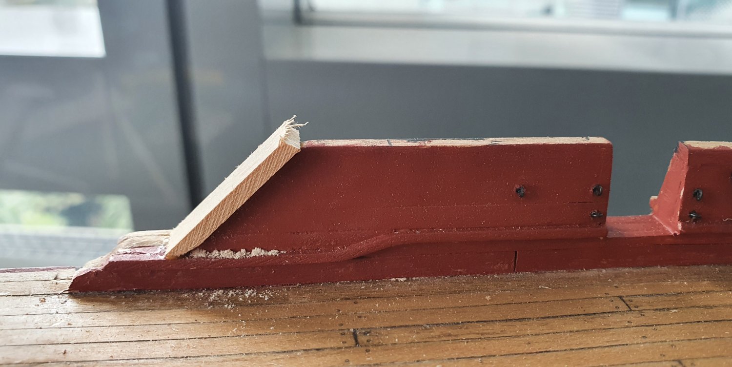
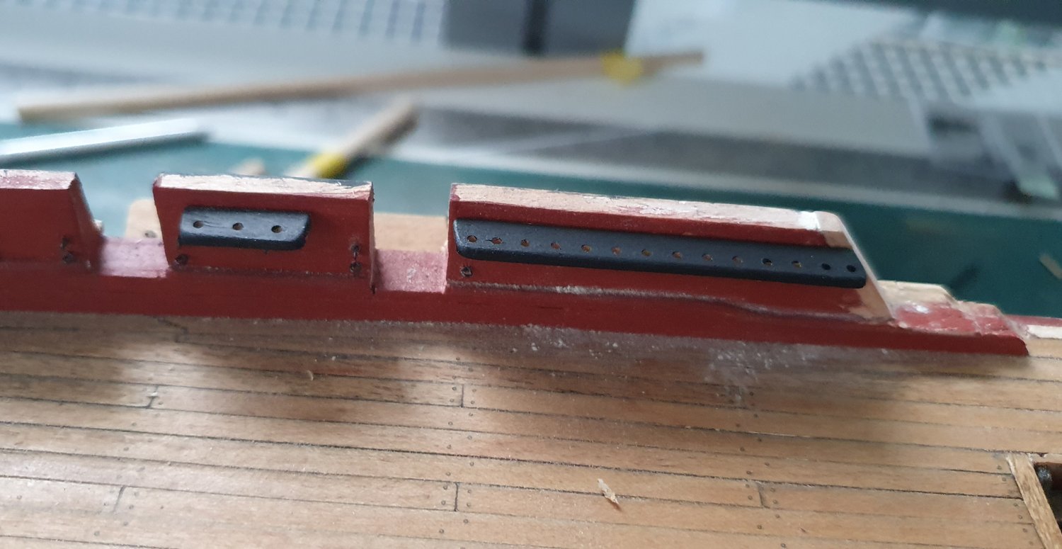
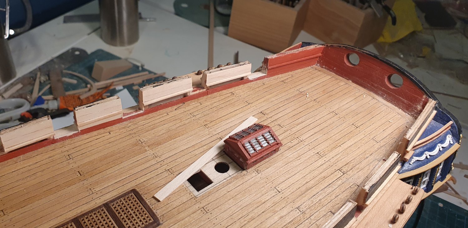
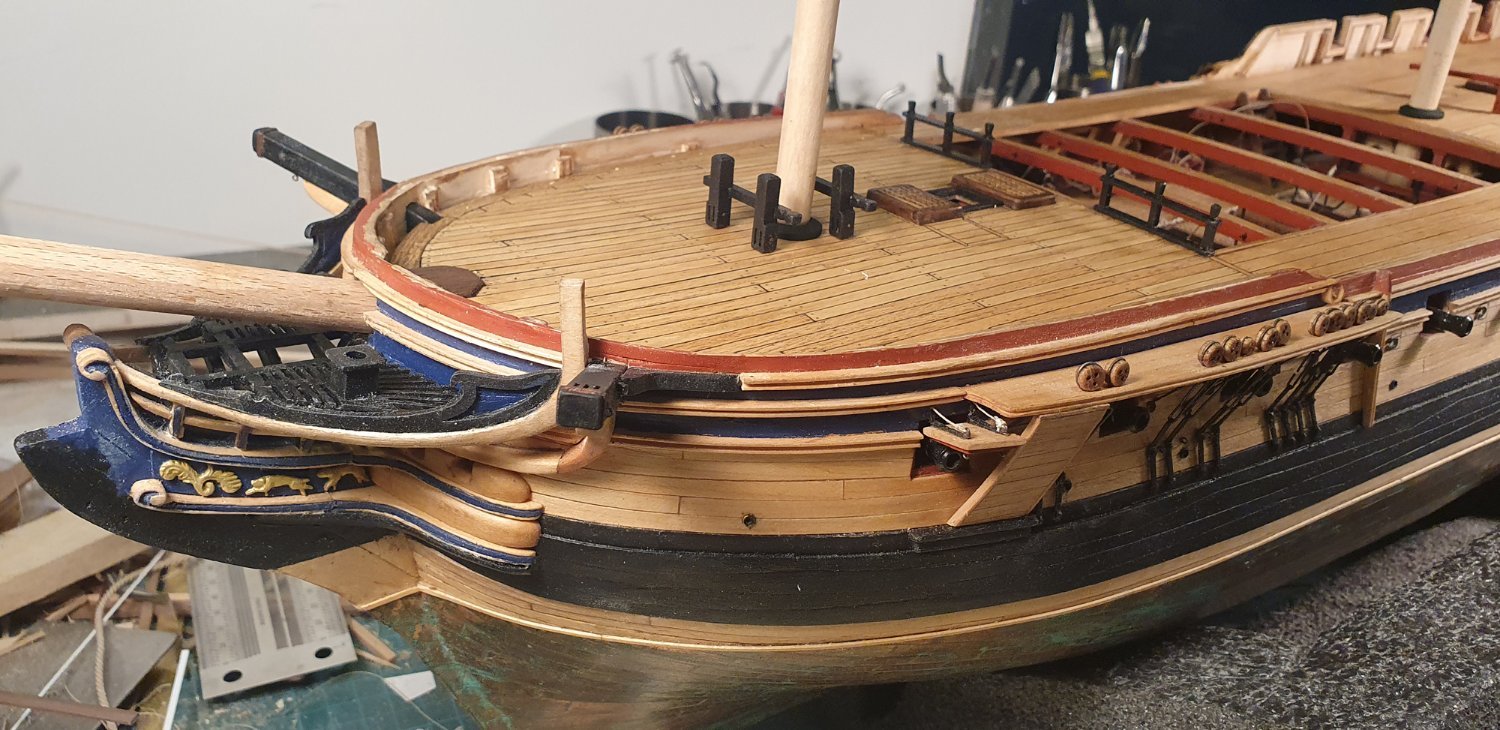
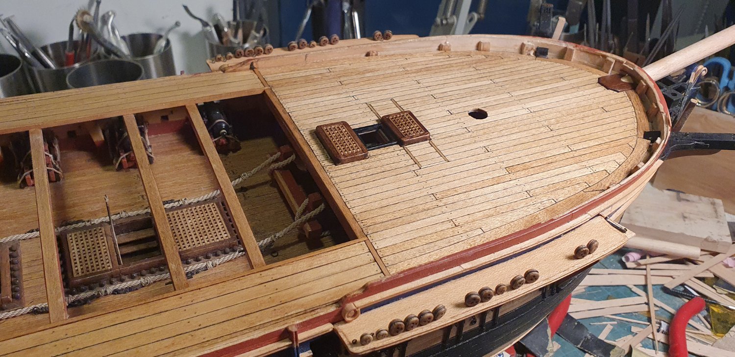
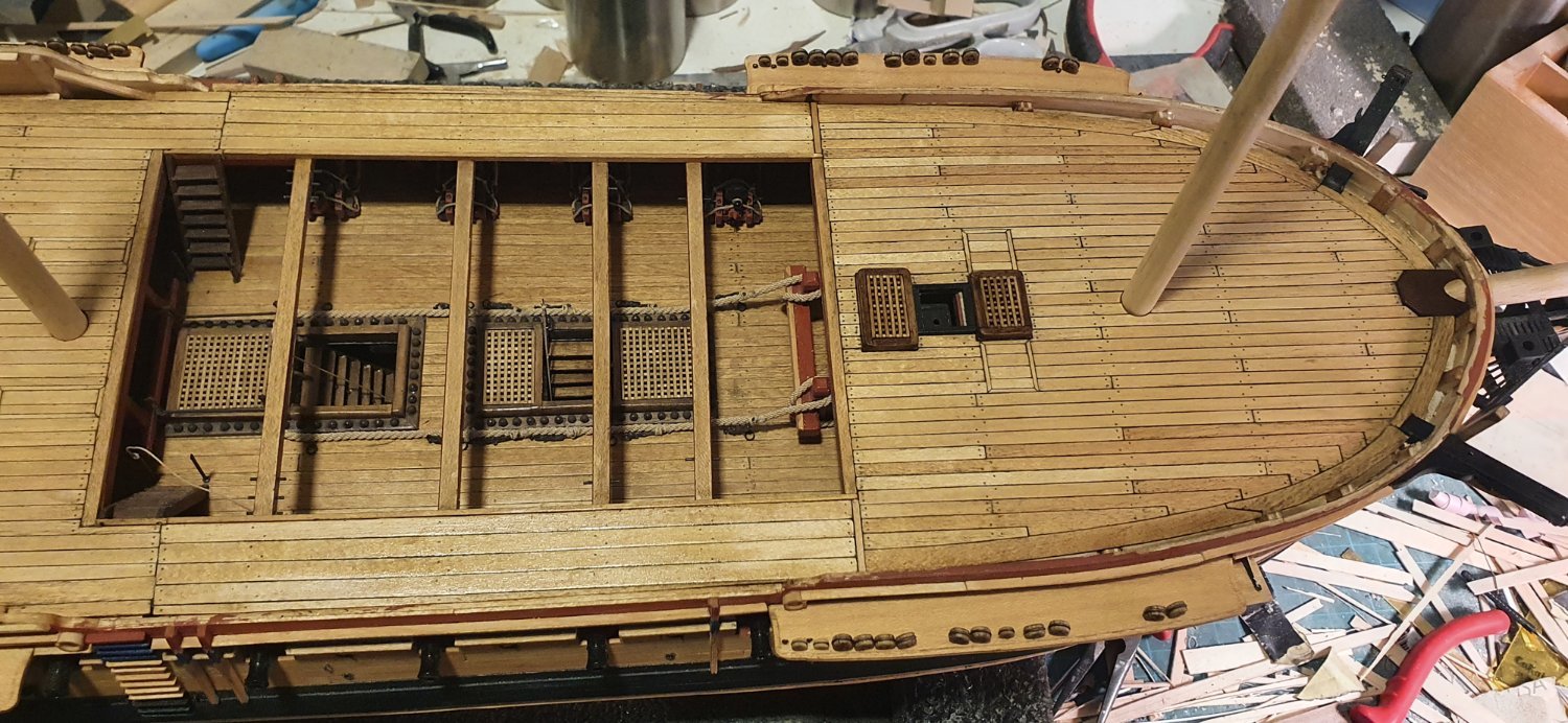
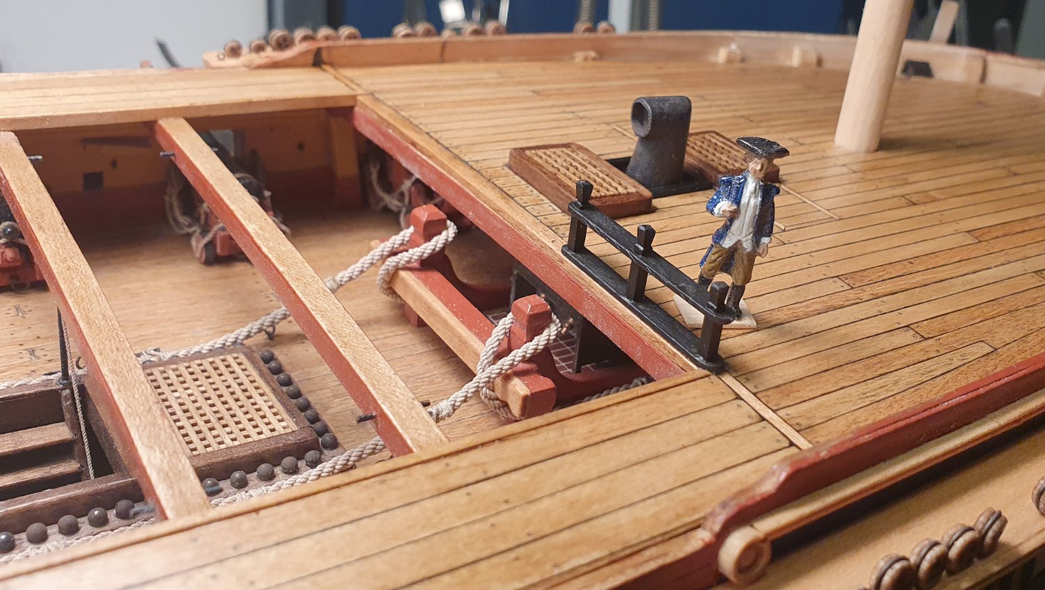
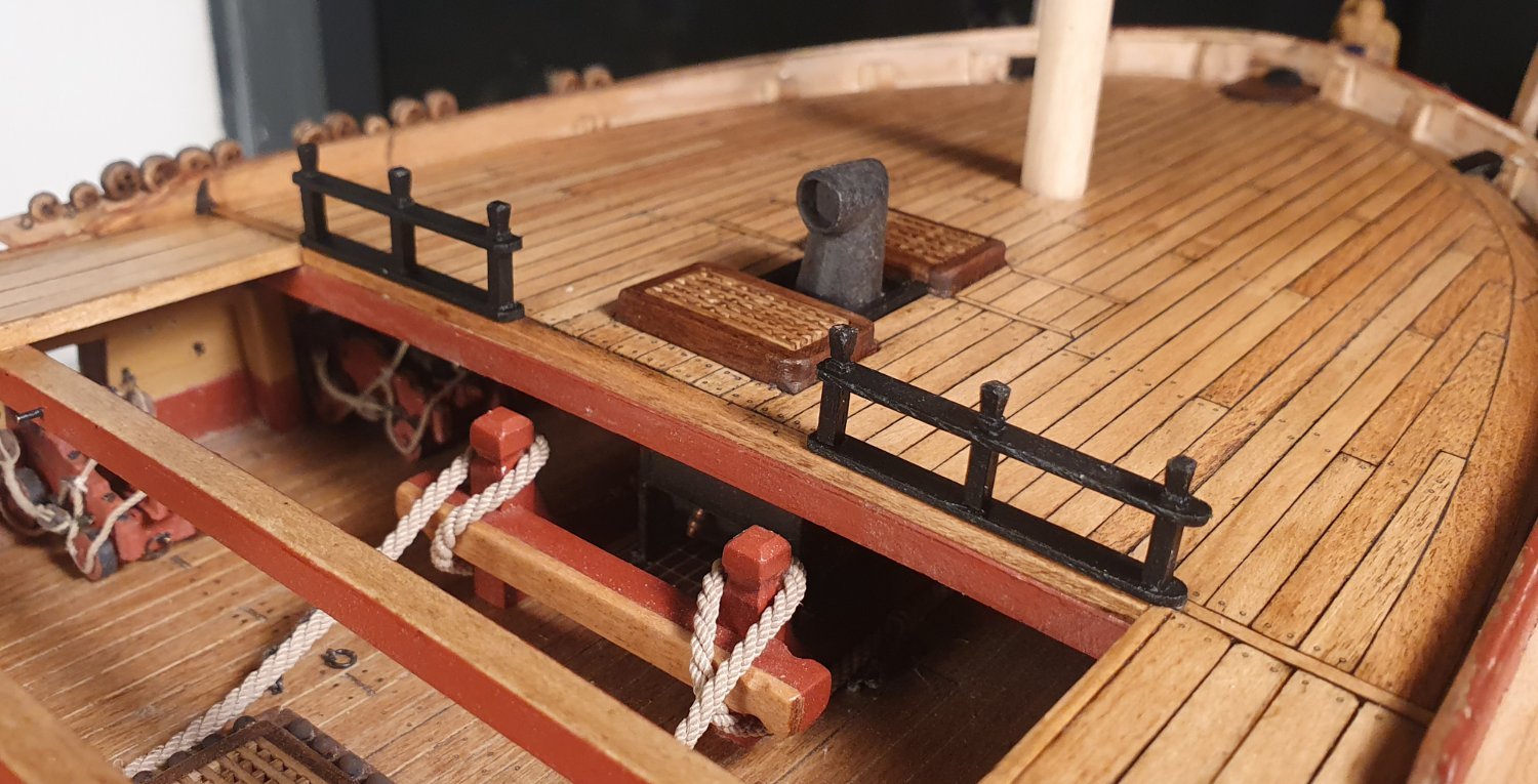
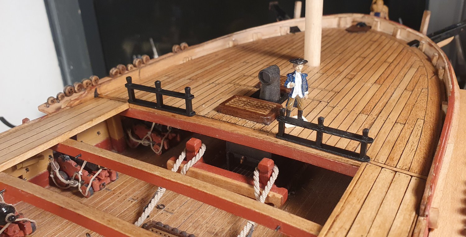
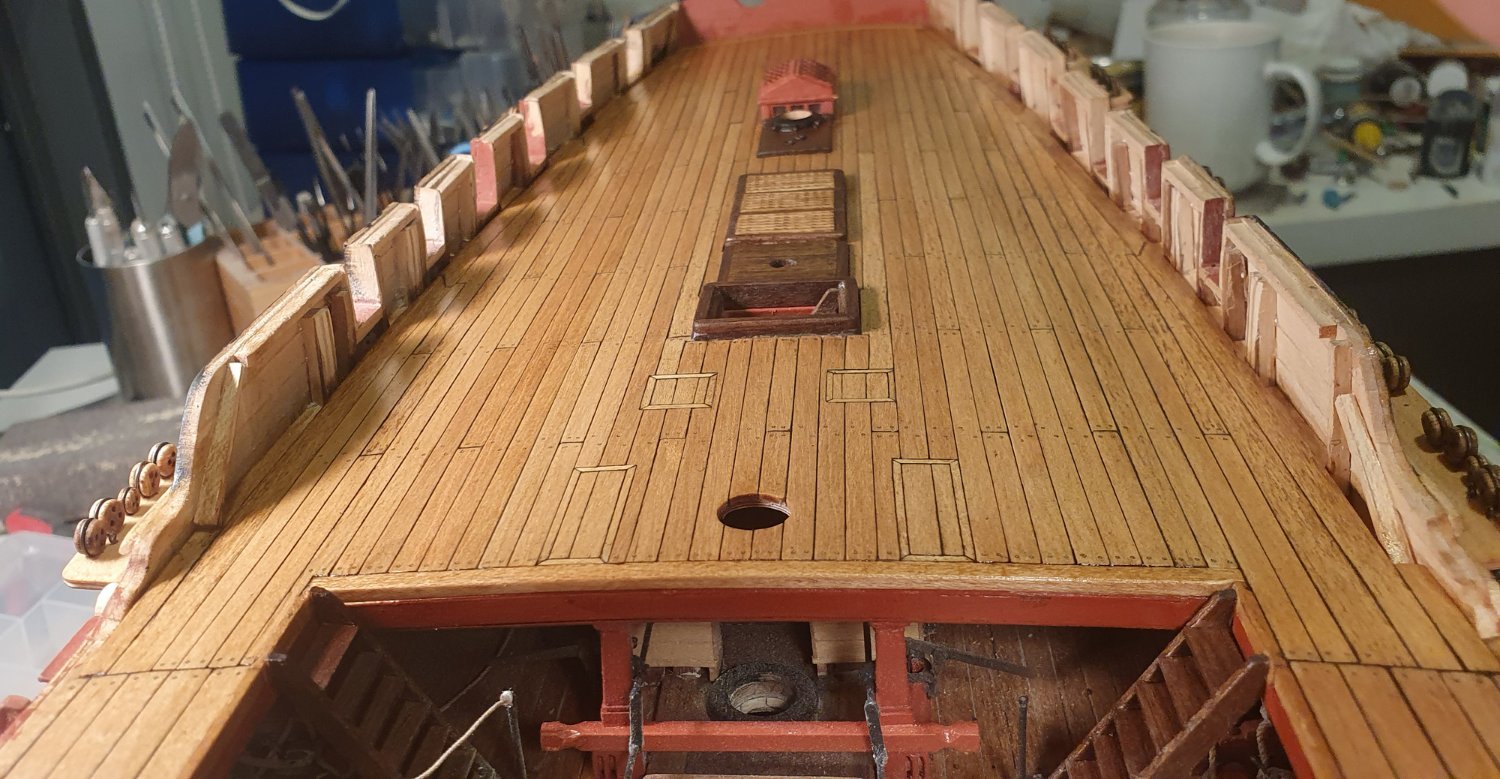
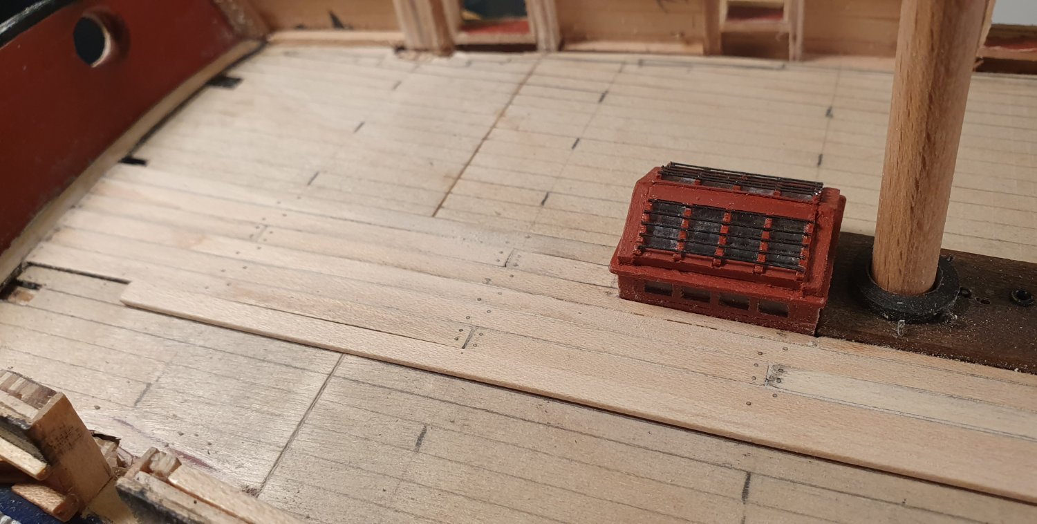
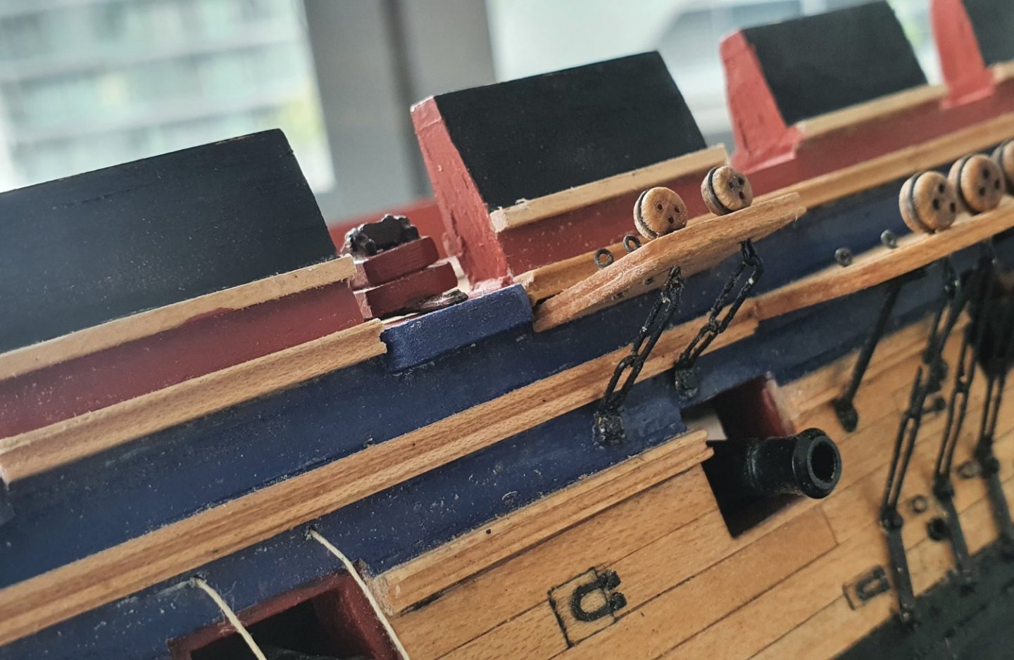
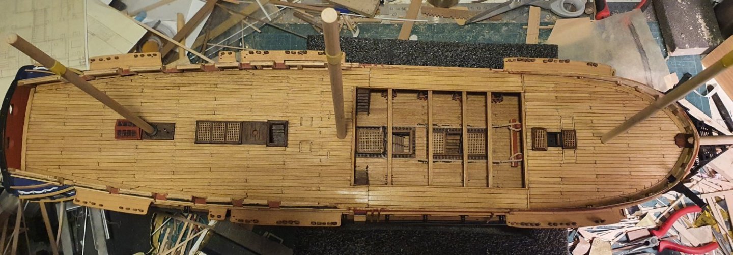
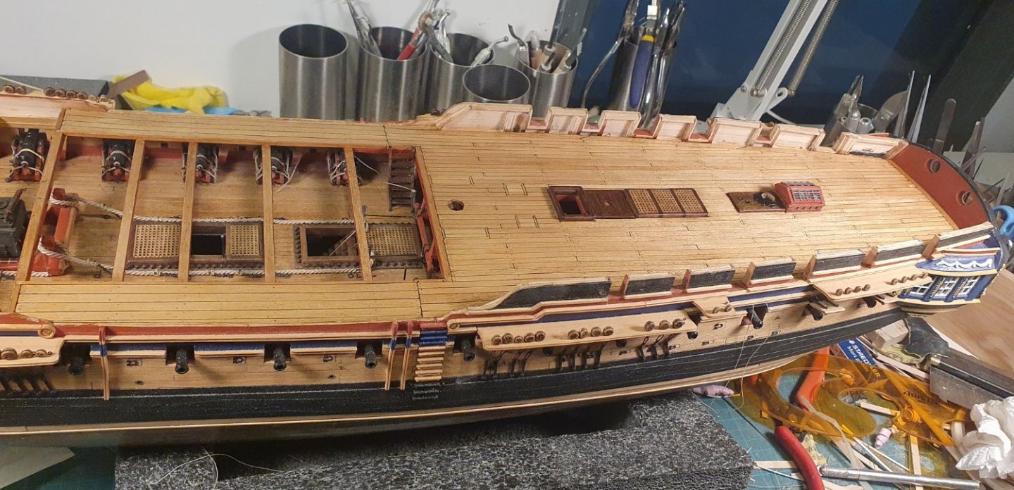
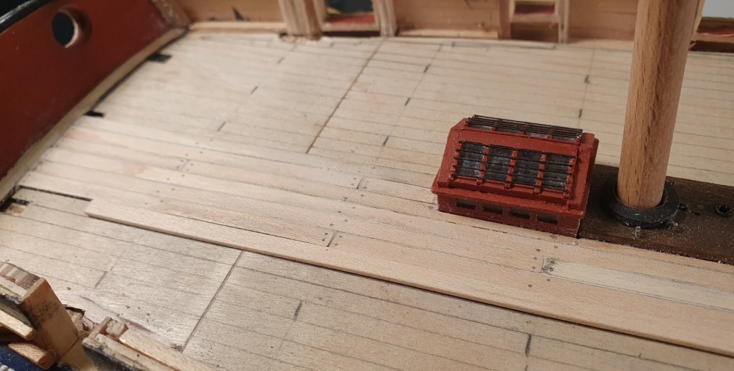
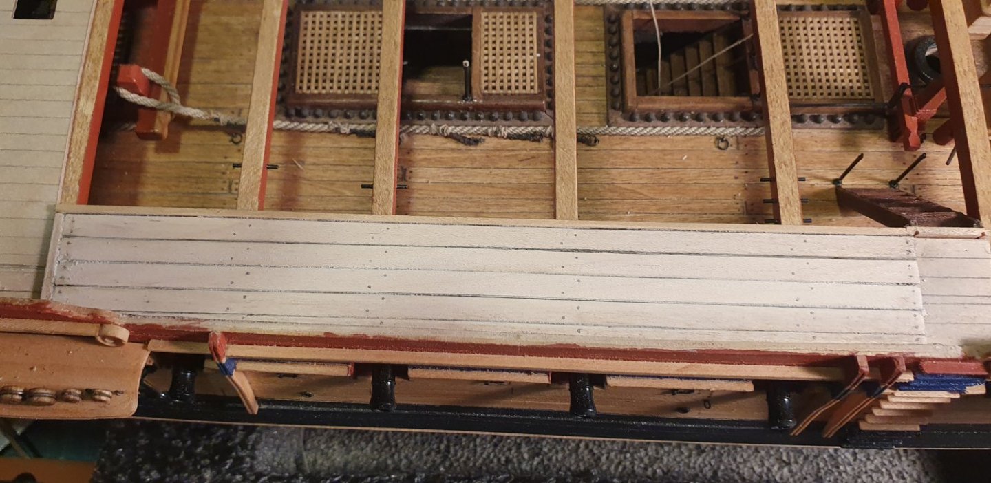
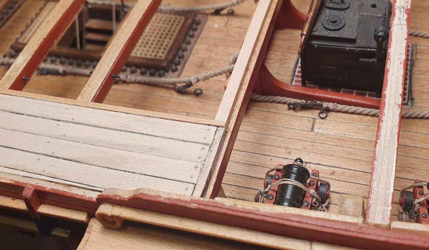
I guess I should post an update rather than just engage in idle chit-chat. I don't have that much to report though. I had the table saw set up for a 4mm plank width and it seemed to make sense to complete the whole deck with a consistent plank width so I continued on and finished the forecastle. I guess I was just idling along as it took longer than I imagined. I certainly was not paying much attention to my plank selection as I ended up with some dramatic colour variations. I am hoping this will not be too evident once the guns are in place. I pinched the step detail to resolve the junction at the bowsprit from Beef Wellington's build. I had a stab at constructing the barricades at the forecastle breast beam. There were subtle differences between the kit version, the AOTSD drawings and the NMM plans so I have built something that is closer to the NMM drawings. I replaced the 1.4mm thick walnut ply horizontals with some 1.0mm thick maple and used 2x2mm walnut for the verticals. This resolves the ugly appearance of the ply edge and looks less clunky. They are just balancing there for the moment as I think they would be vulnerable to damage if I installed them at this point of the build. I may drill in some pins when I do the final fix to give them a fighting chance. The chimney is not fixed in place as it needs some additional detail.


-
Thanks Vane. I hope you will be back working on your own Diana soon as I was really enjoying your build log.
-
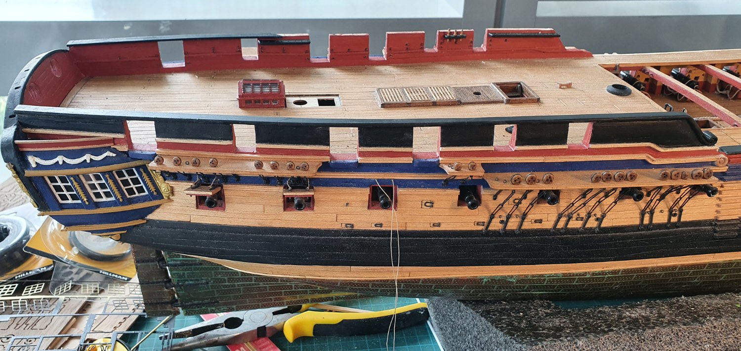
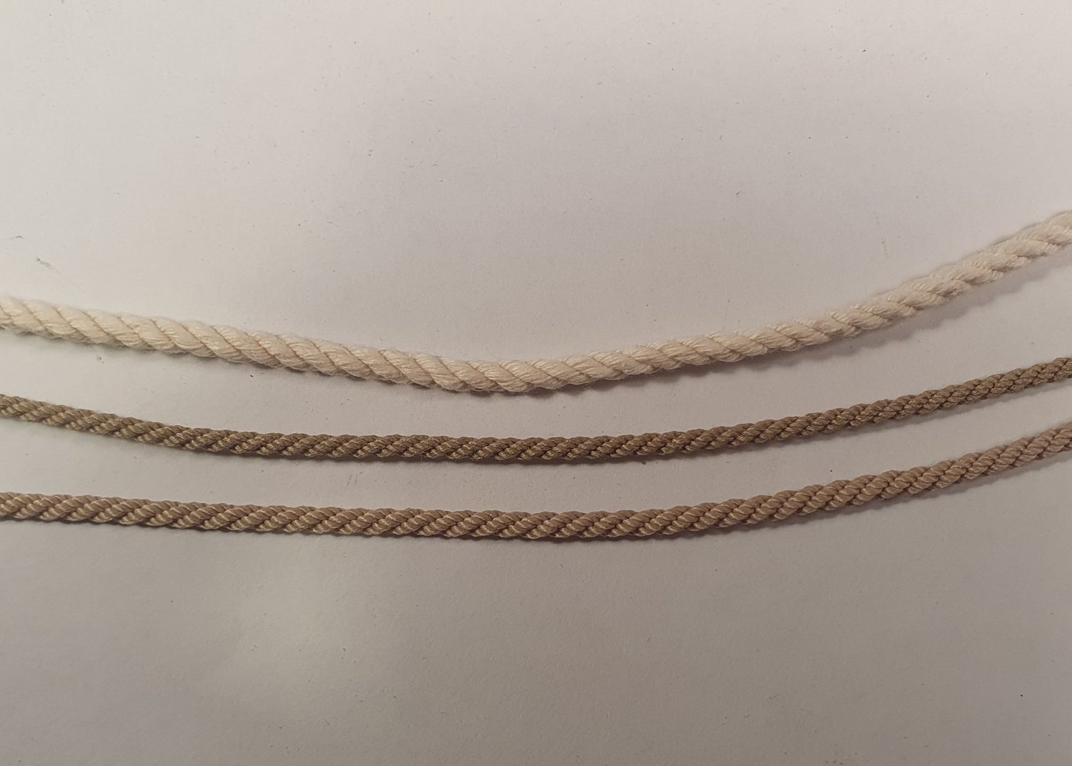
A small update. My 2.4mm diameter polyester cable laid rope arrived from Ropes of Scale. Looking at the photo it was not dramatically different to the one that I had already installed so I was in two minds as to whether or not I was going to replace it. I eventually did but caused a lot of collateral damage when ripping out the old one. I dislodged shot lockers, lost cannonballs and tore out deck ringbolts. I was thinking that I had made a huge mistake but I persevered and think that the larger diameter does look better. I finished planking the quarterdeck. Not entirely happy with how this turned out and it revealed some dramatic asymmetry in my underlying structure. My carronade ports look like they have been built by the three bears. One is too low, one is too high and one is just right. I guess that it can all be disguised once it gets covered with equipment and rigging and when it becomes dustier and grimier. I now have to decide if I should press on and plank the forecastle or take a break from planking and do something else for a change.


-
Thanks B.E. I am a fan of your Sphinx build log. That is a fine looking model you have on the go. Regards, David
-
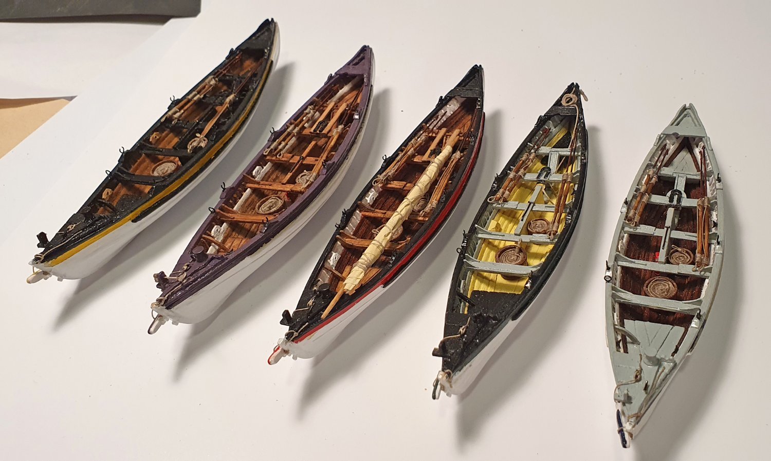
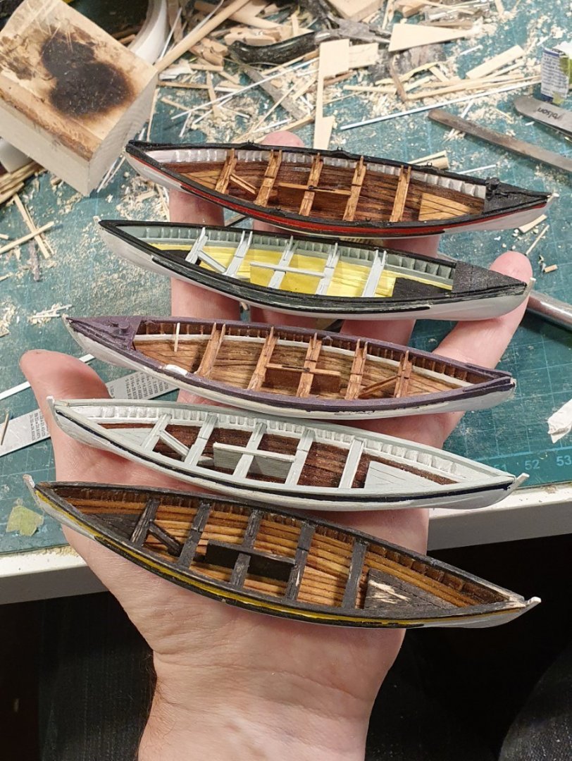
Thanks for the kind offer Allan but I am probably suffering from too much information for these boats. The limiting factor is the 1:64 scale which somewhat dictates the level of detail that can potentially be included. I had already ordered the W.E. May book a while back but it has yet to be delivered. I still have to decide on the number of boats I will include. Five may be historically correct but fitting them all onto the model would be a challenge and I guess I would have to introduce those illegal stern davits and possibly quarter davits but I would want to avoid covering up the stern detail. Philosophically I like the idea of four which would be one of each type but there is a tradition of not including all of the boats on contemporary models which would have the advantage of allowing views into the waist. Another option would be to include three and have the largest hoisted as though it were being launched. This would open up the view into the waist and add some interest to the rigging. I have quite a bit of time before I need to make up my mind though. Regards, David
-
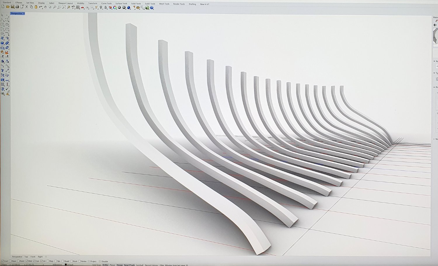
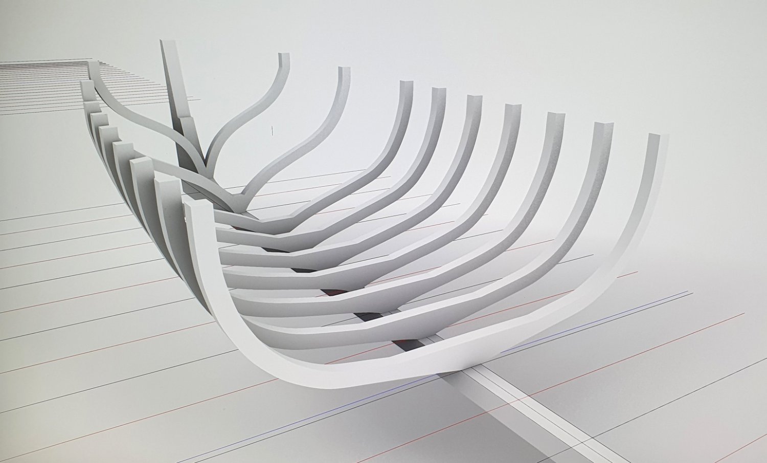
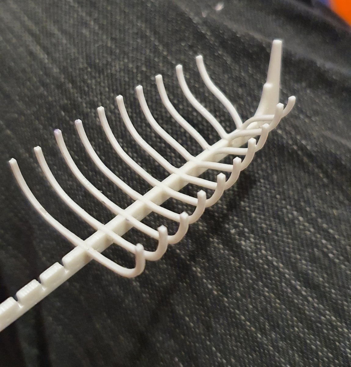
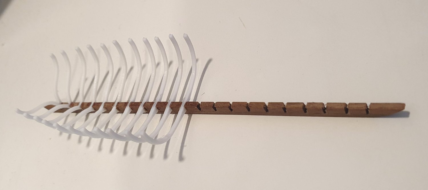
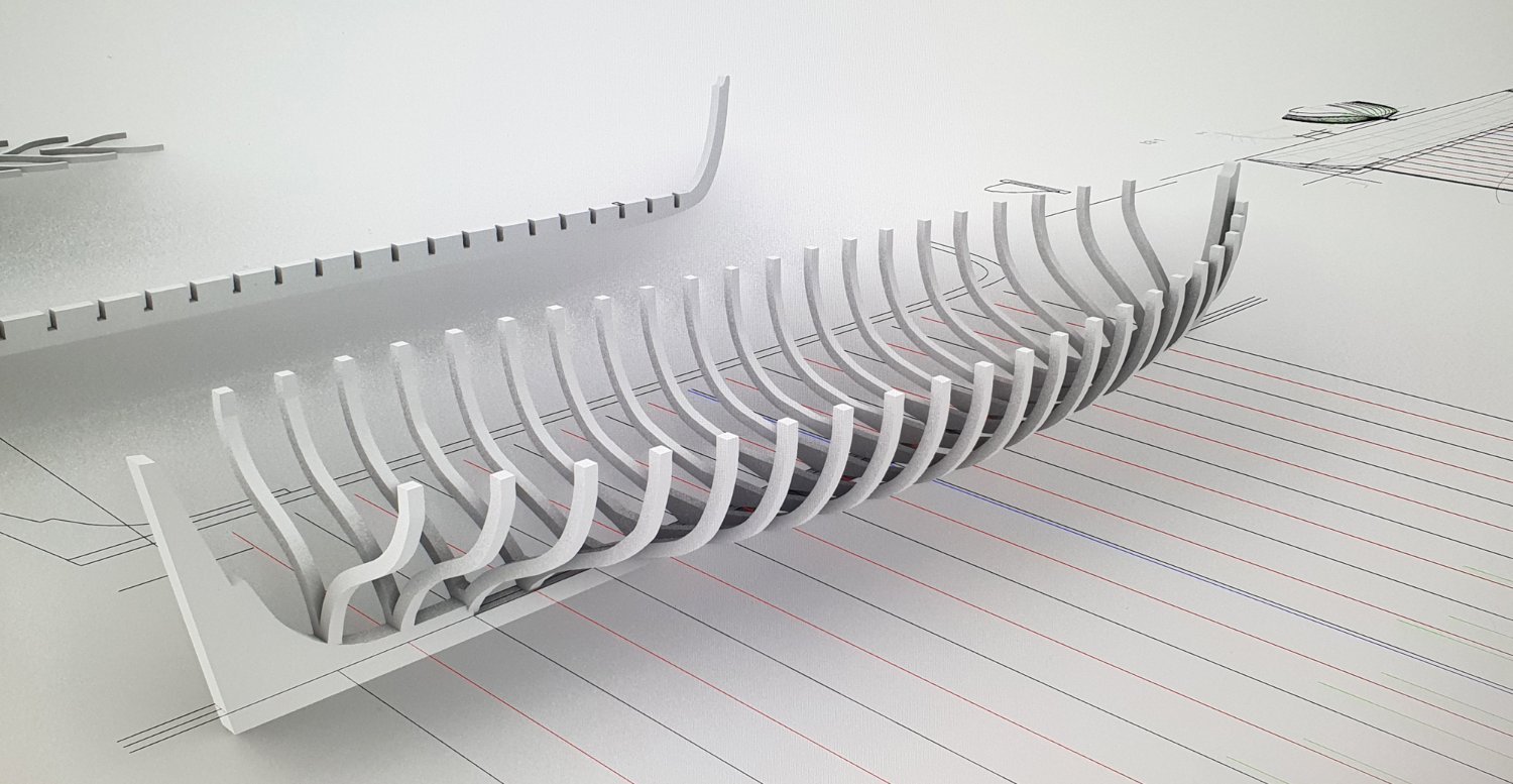
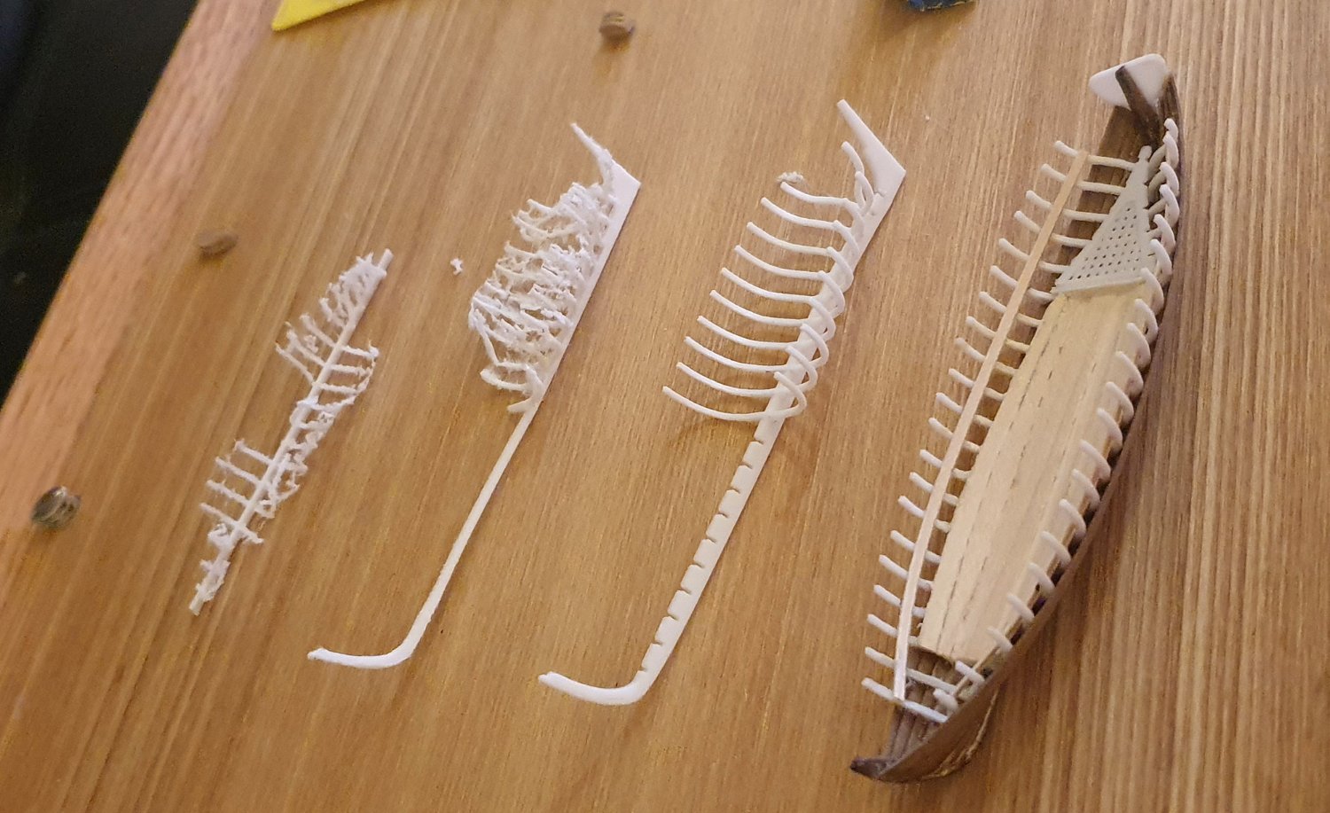
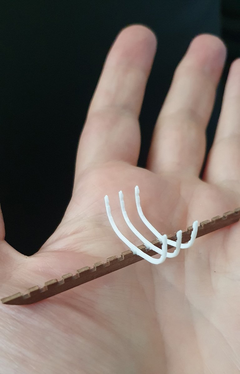
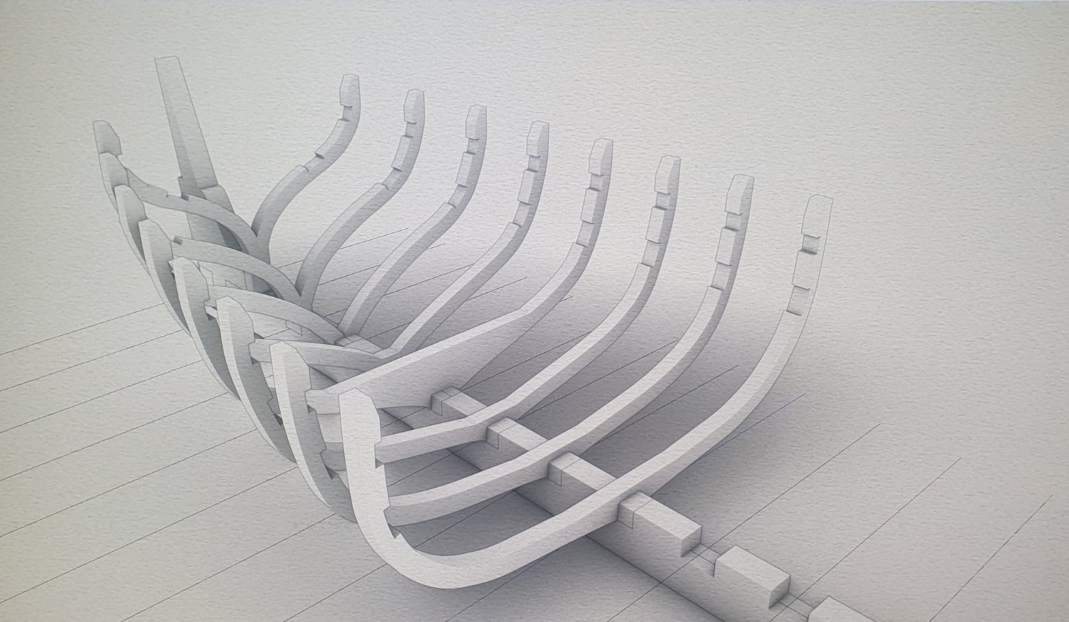
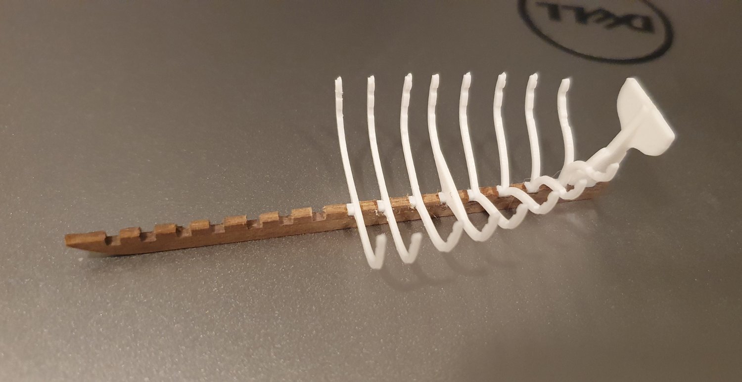
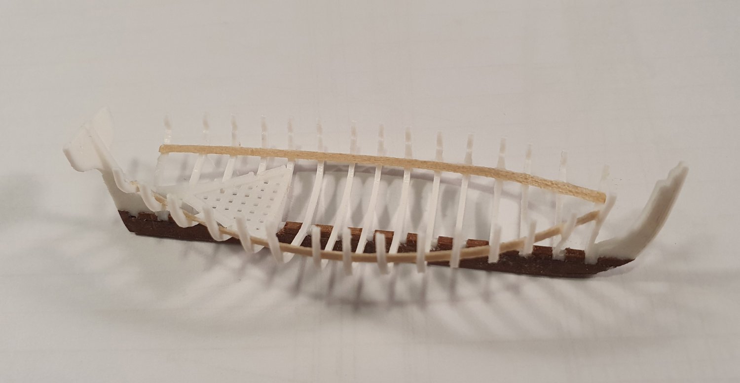
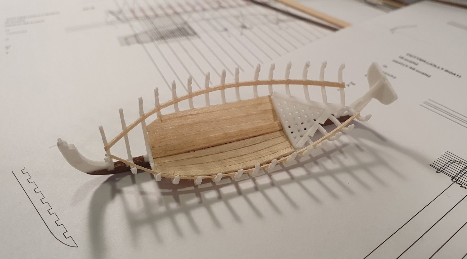
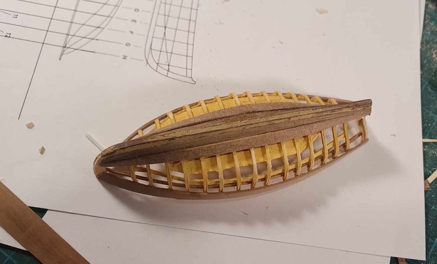
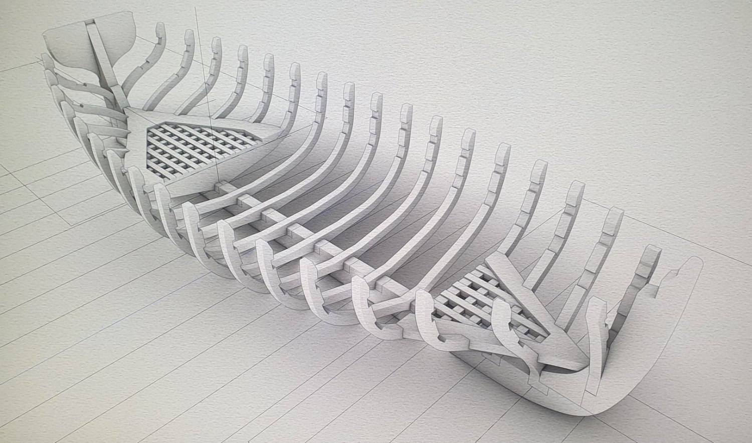
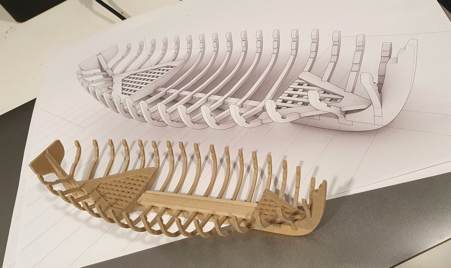
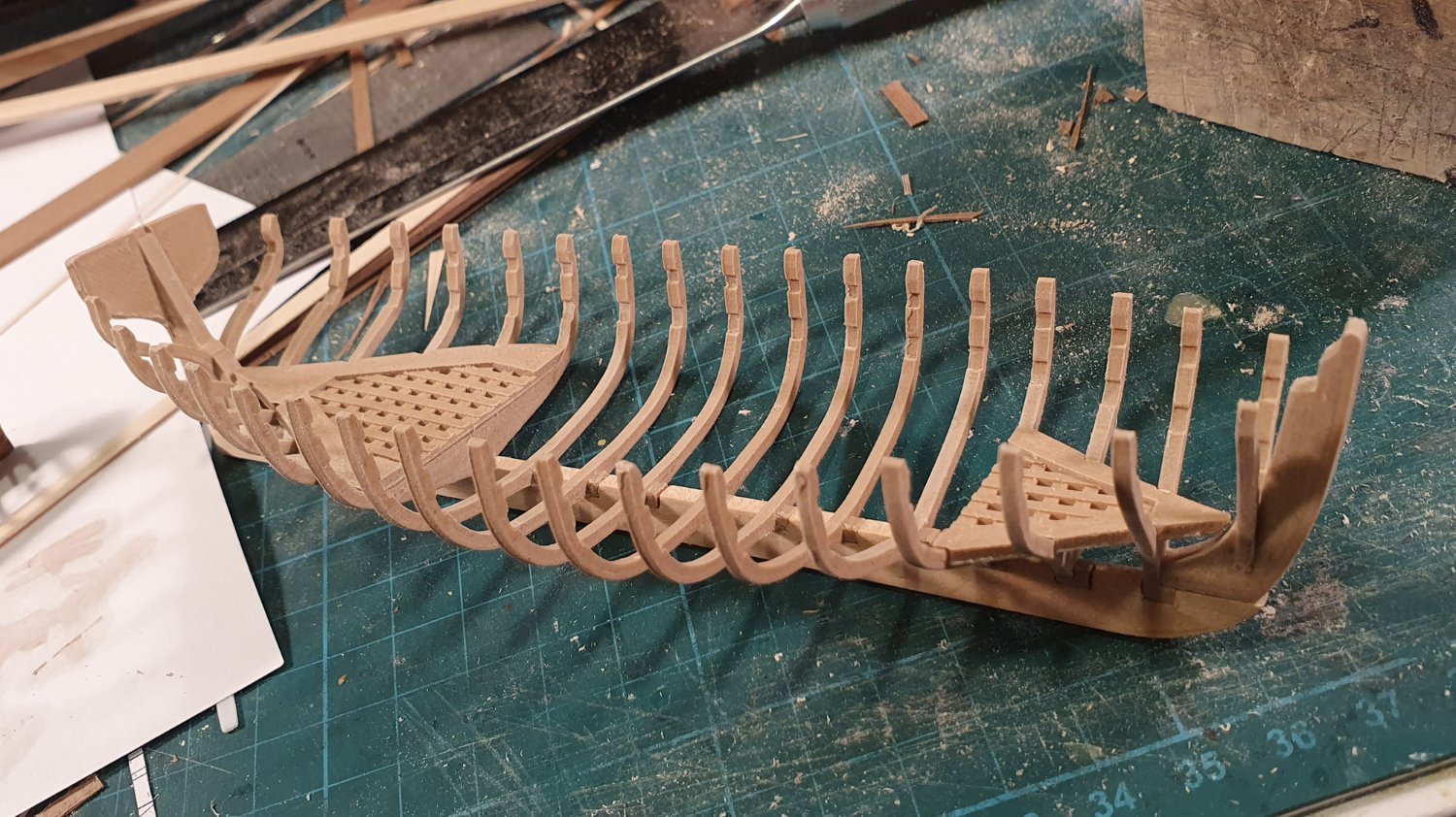
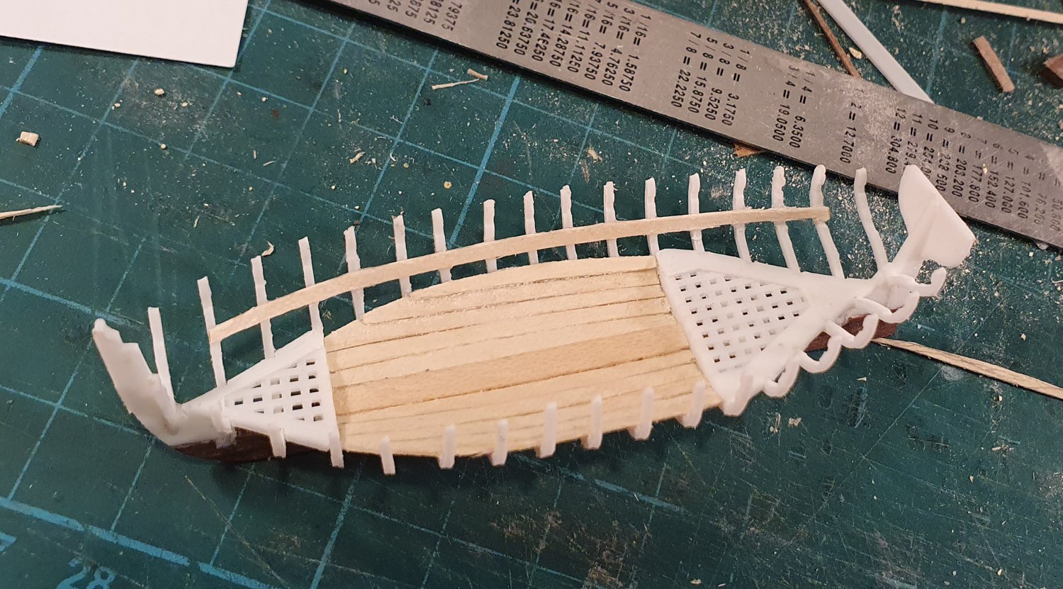
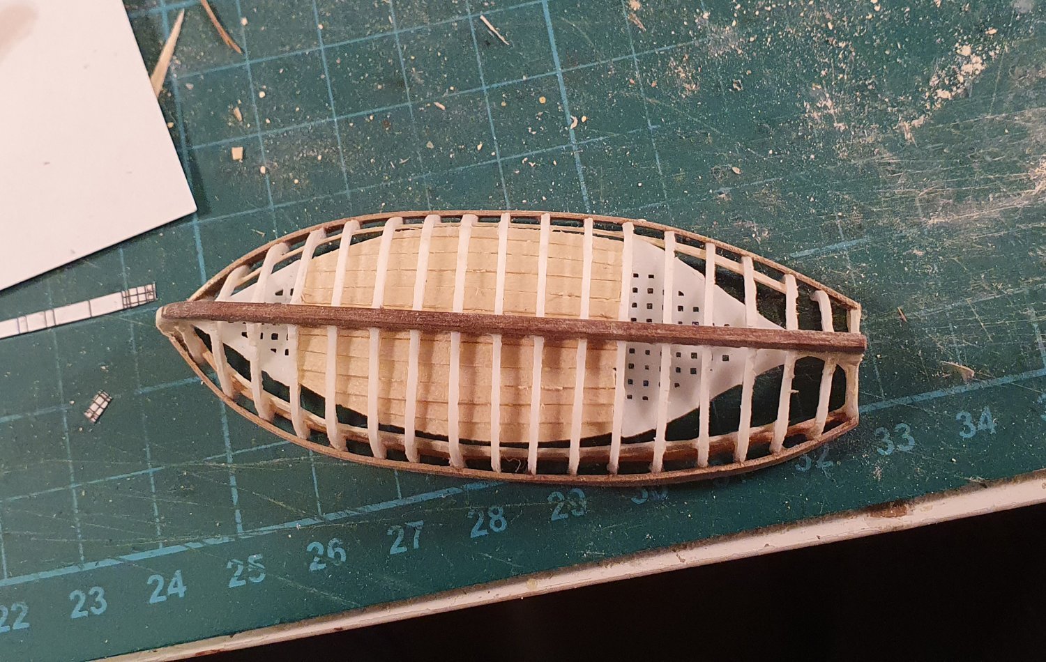
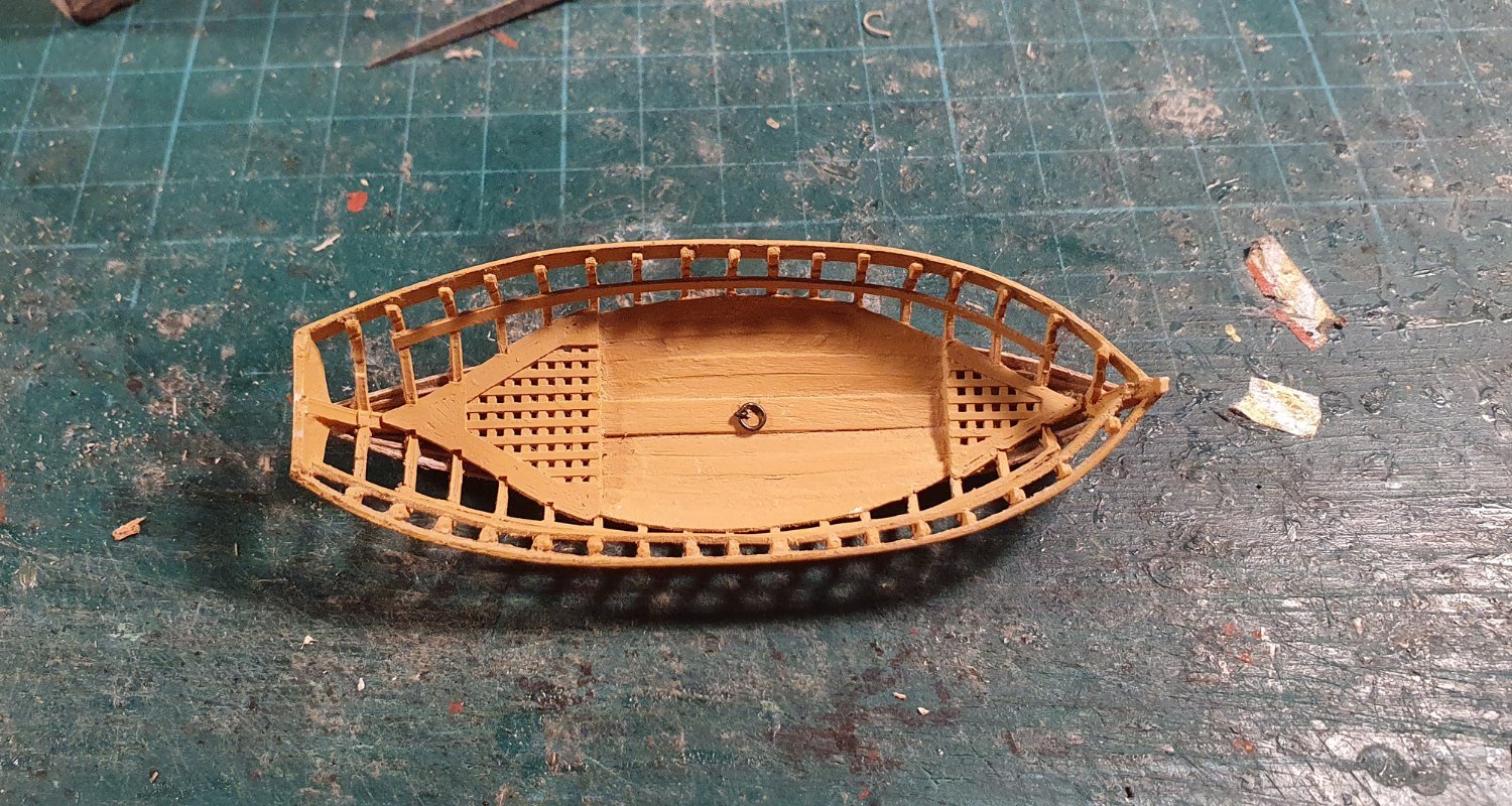
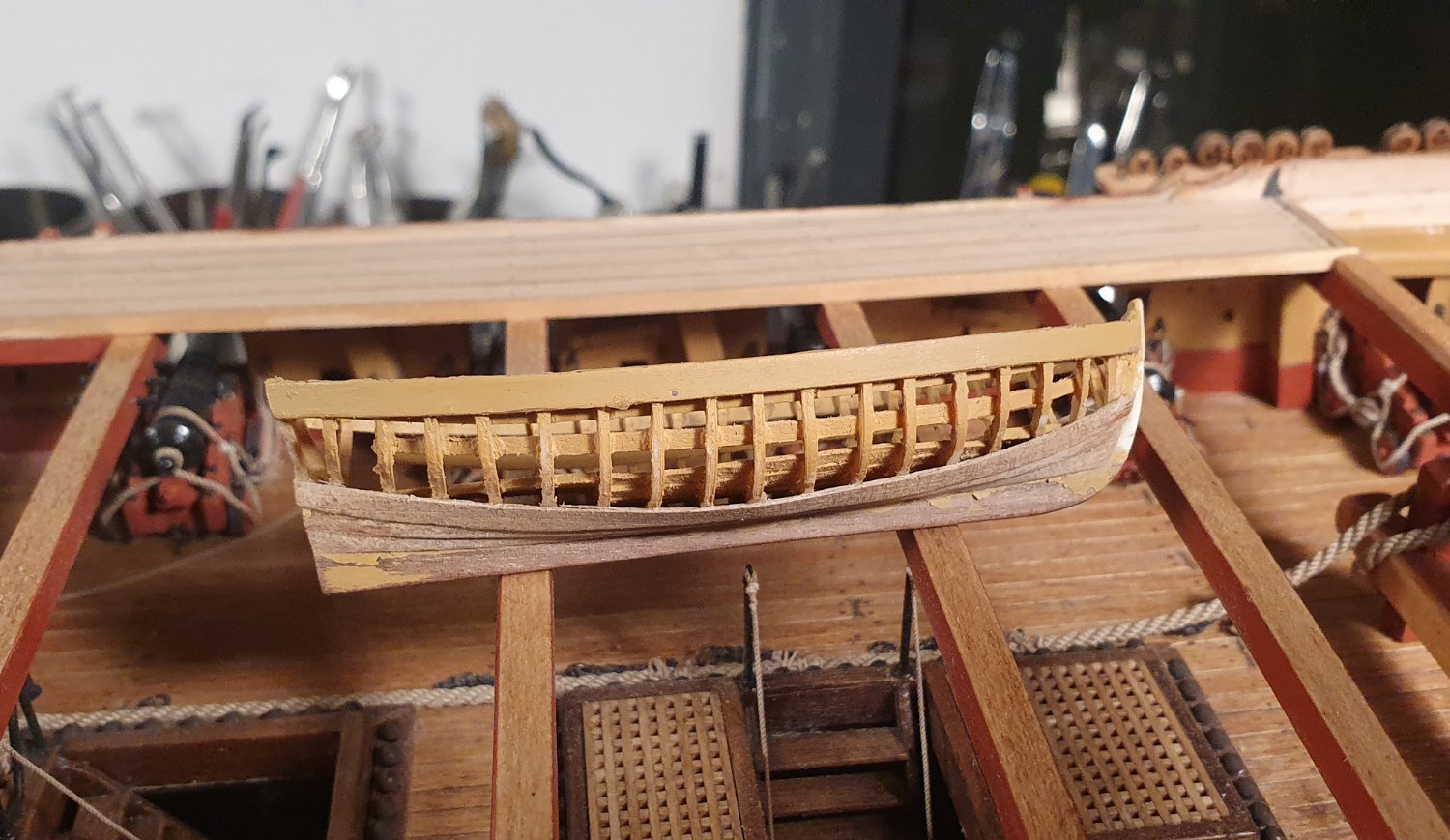
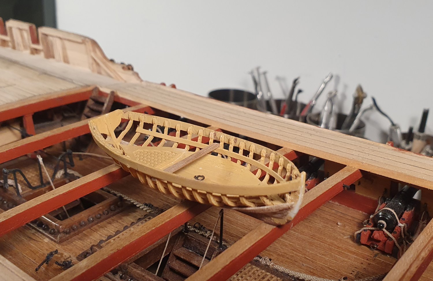
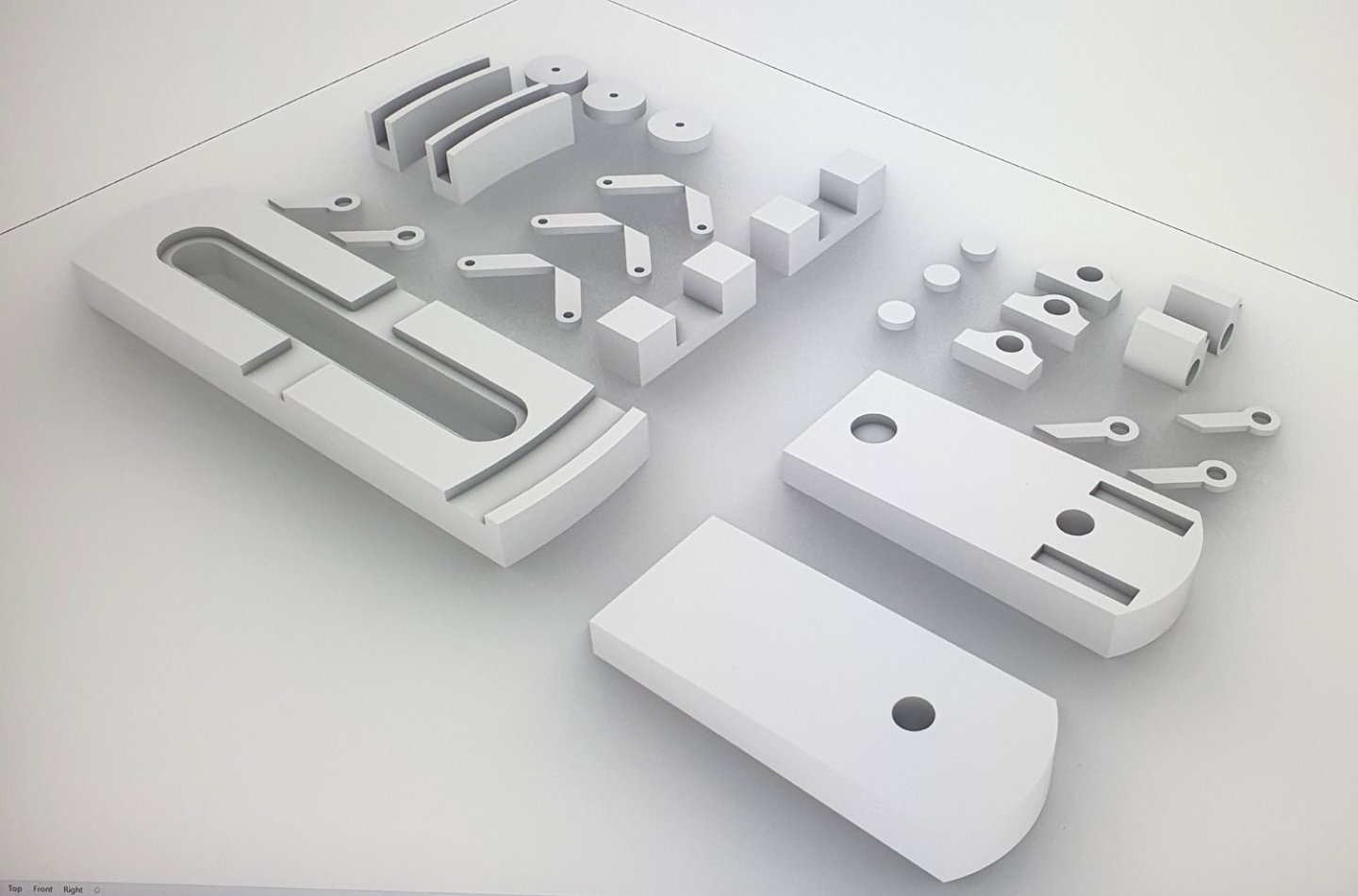
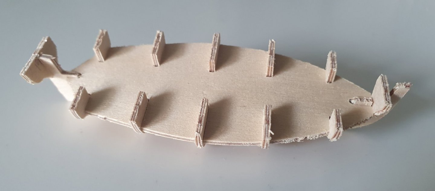
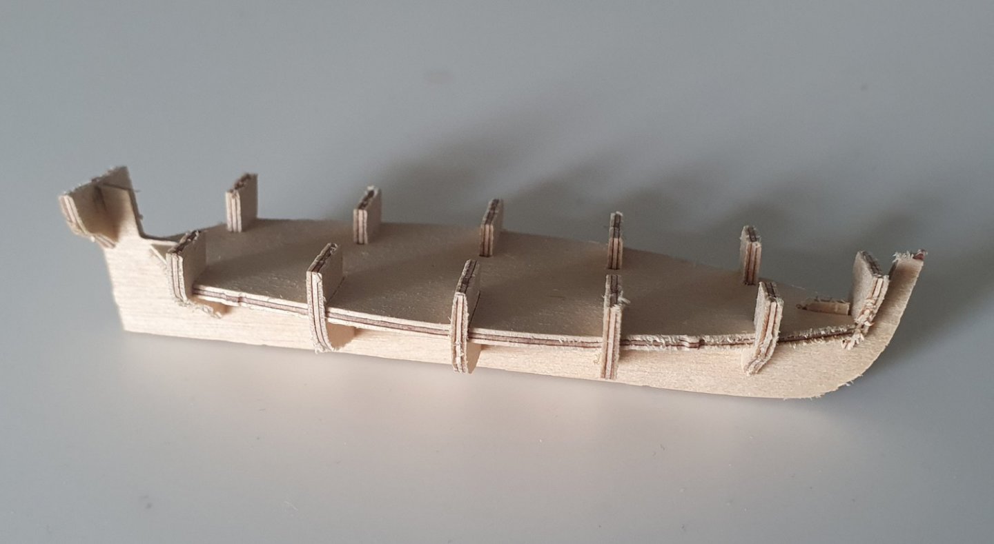
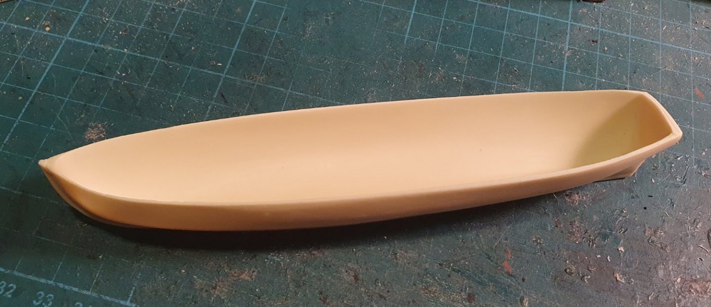
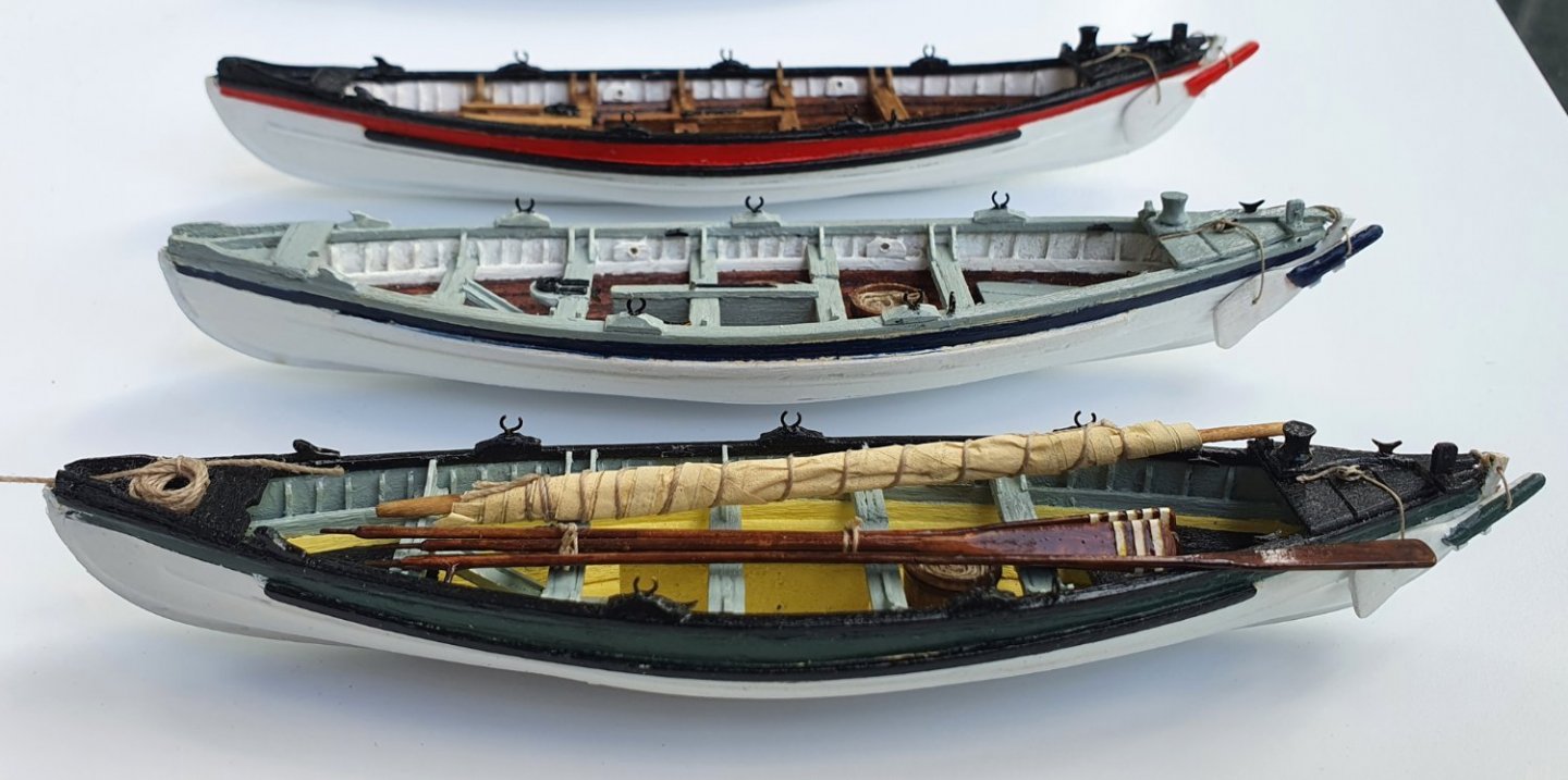
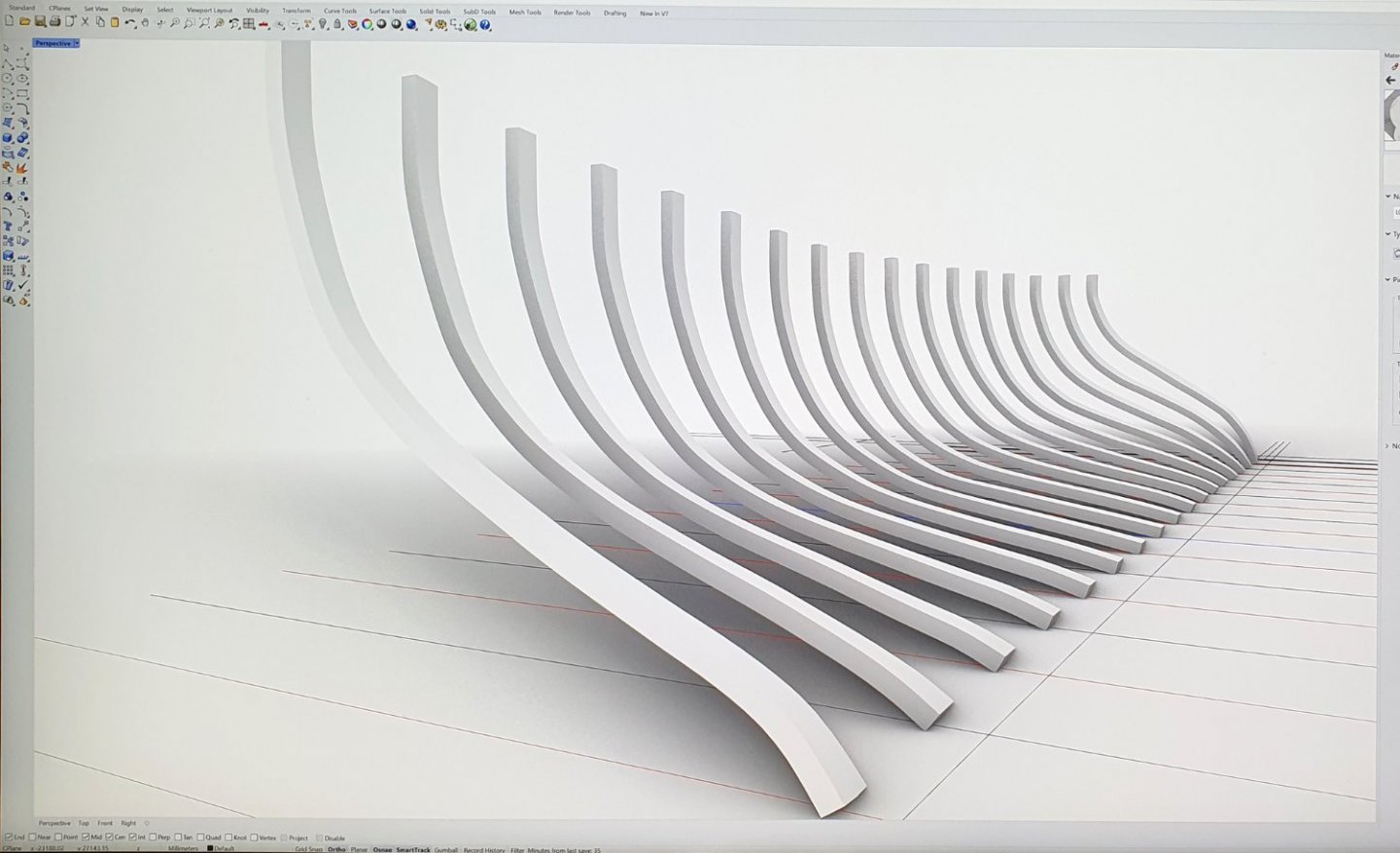
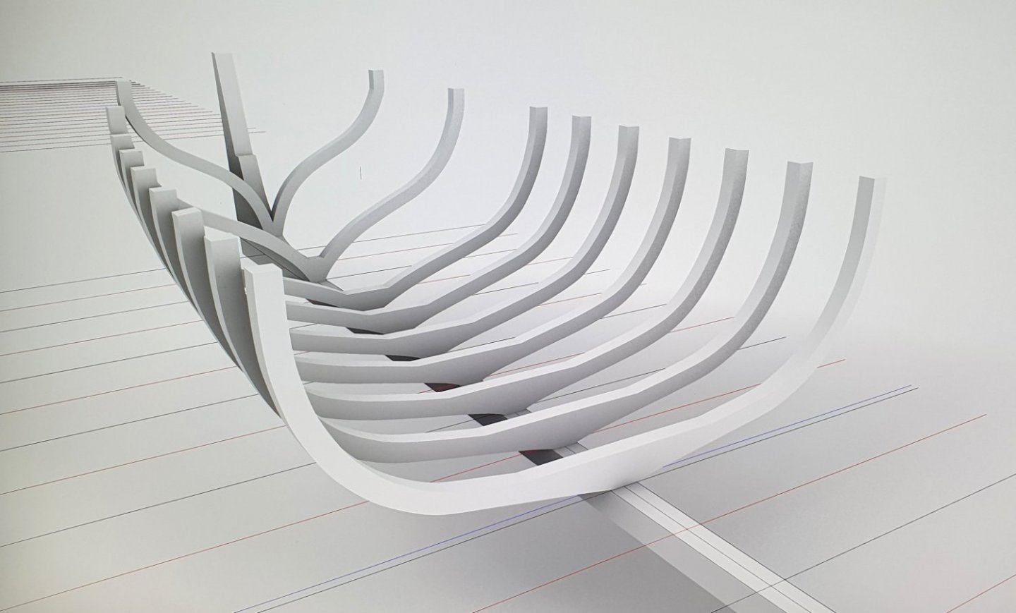
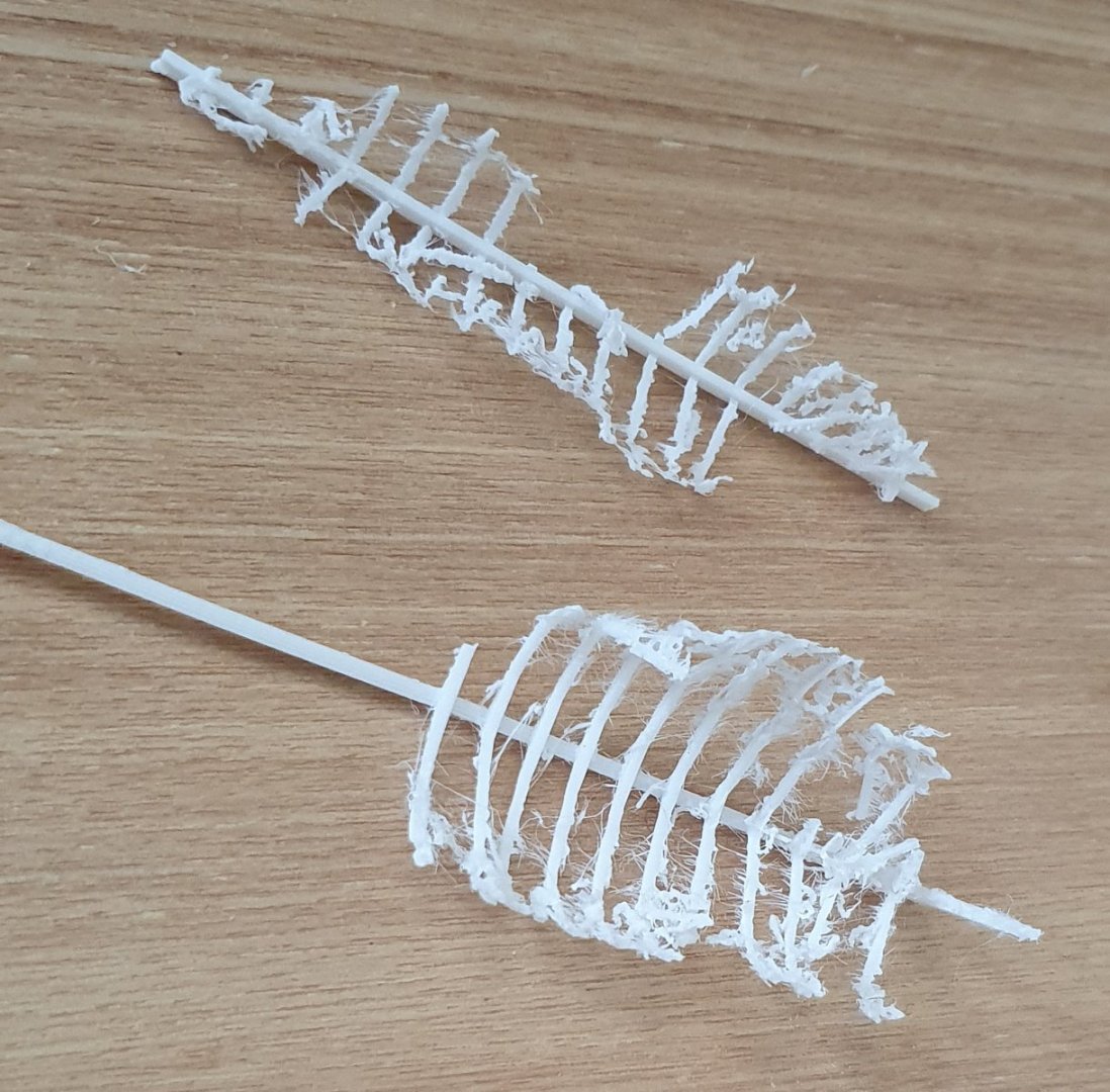
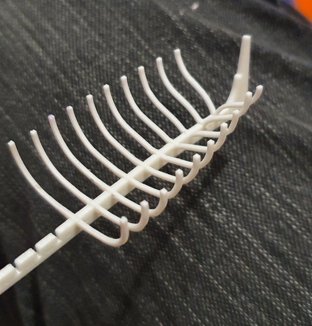
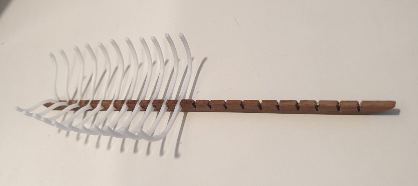
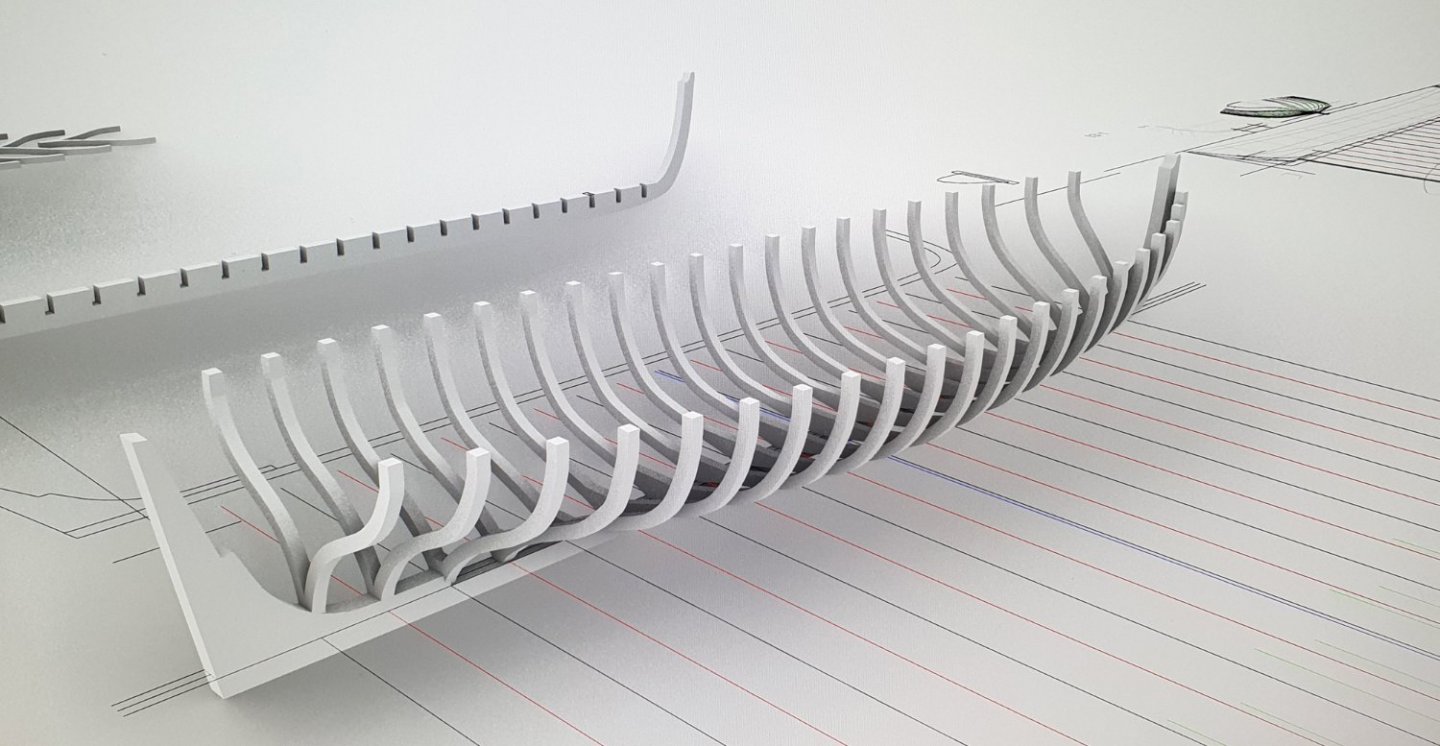
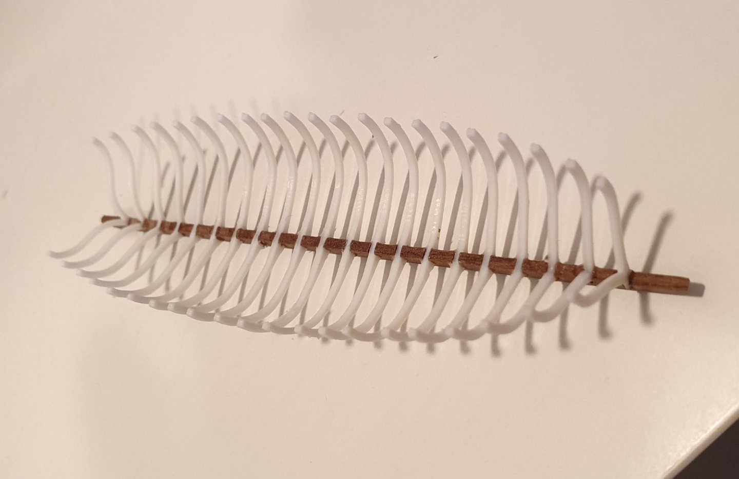
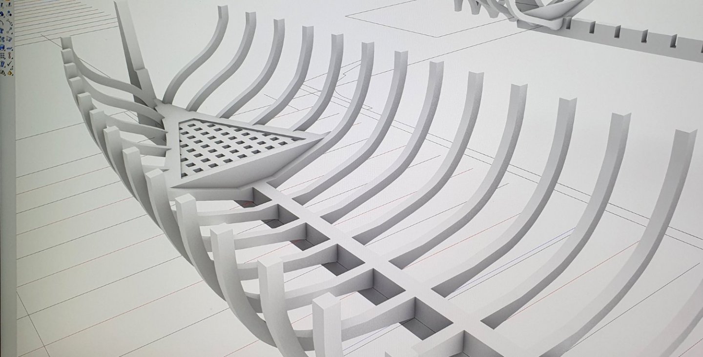
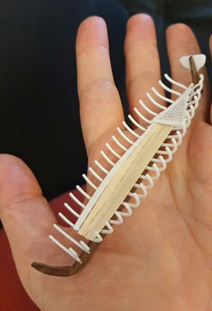
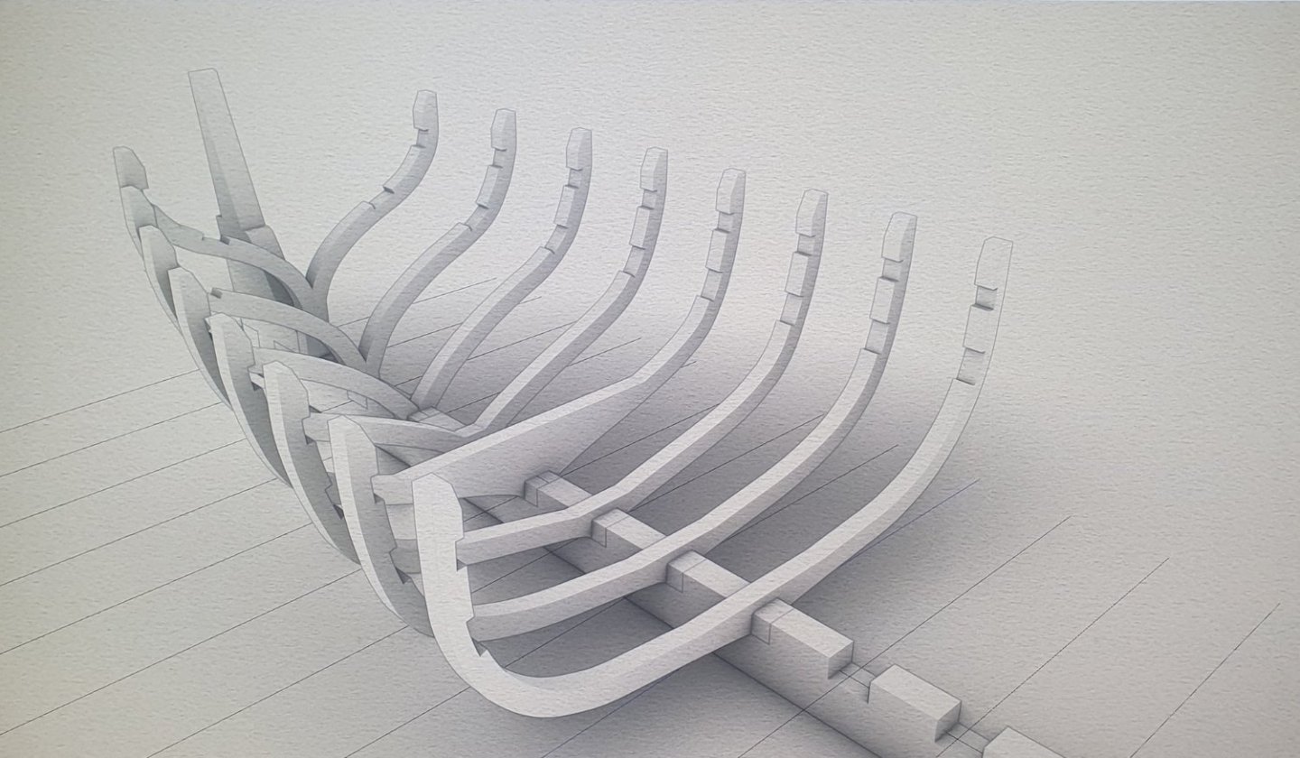
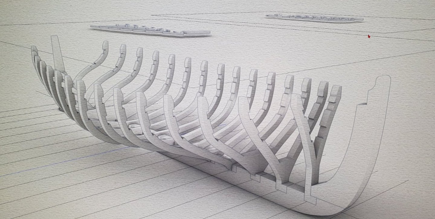
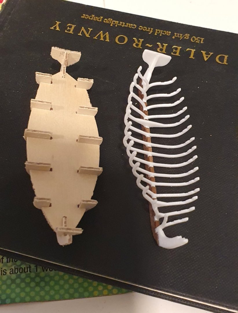
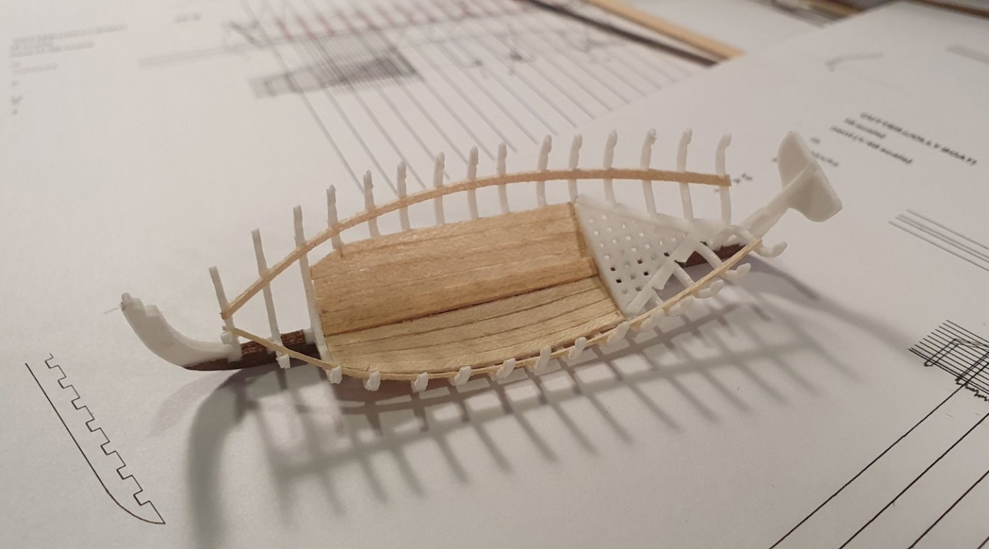
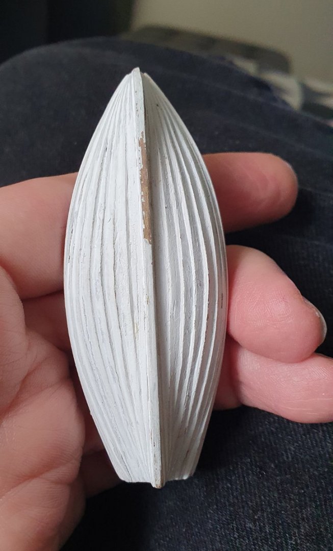
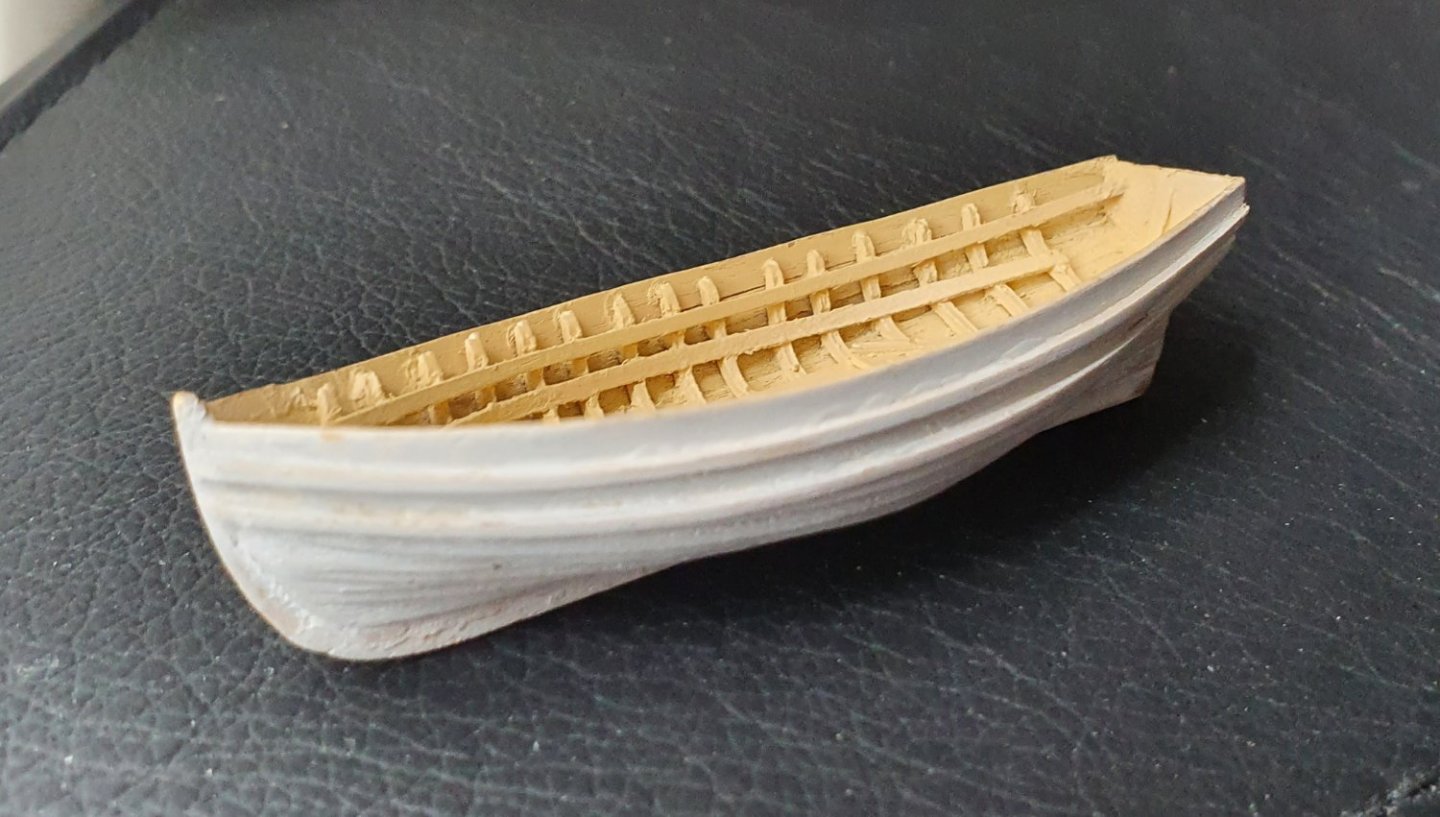
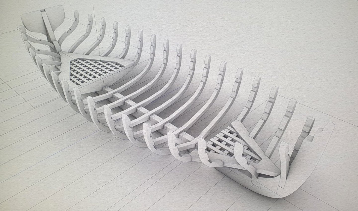
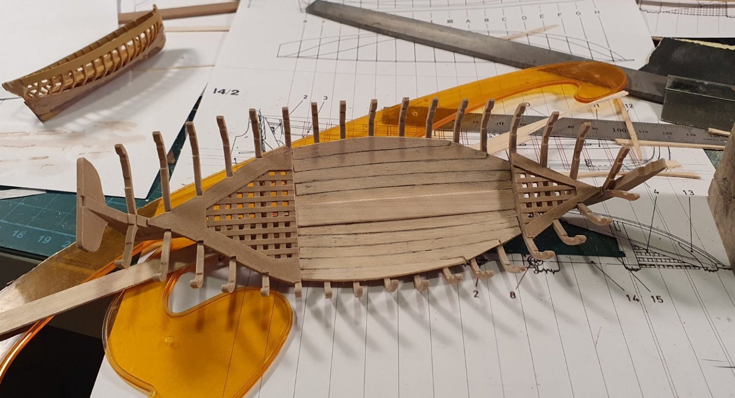
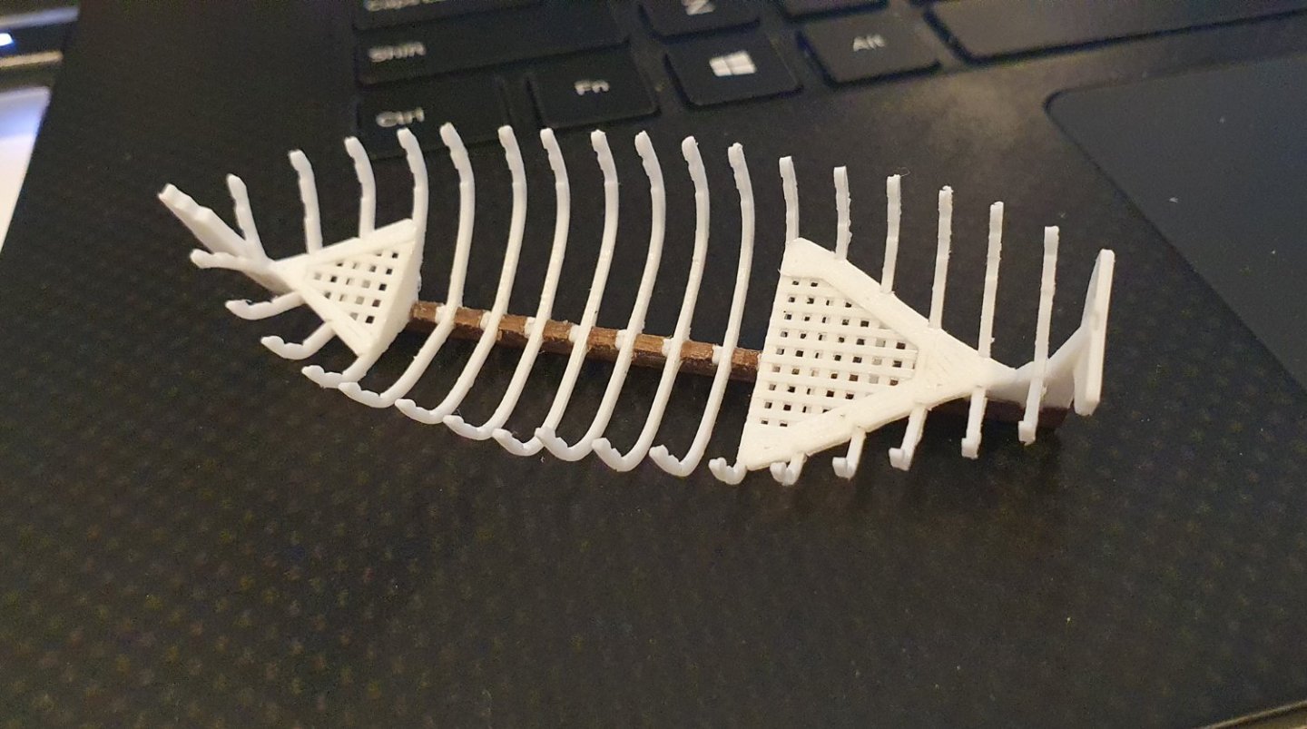
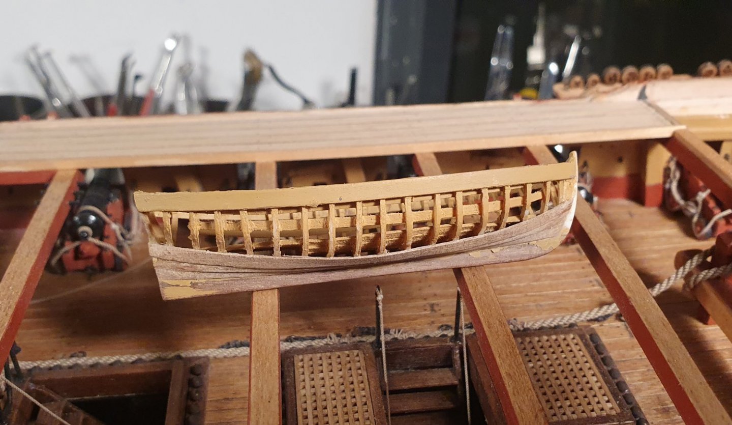
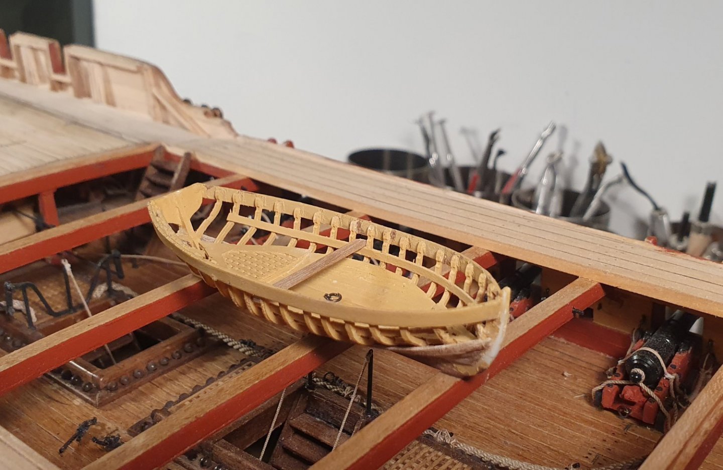
Parallel to the deck planking I have been fiddling around with the ship's boats. I made up the structure of the jolly boat using the kit parts. The supplied ply is fairly thick and results in the floor of the boat sitting quite high. Any sailor using the boat would be rowing with their knees up around their ears and I imagine they would be less than jolly. I purchased one of the Caldercraft upgraded mini kits which is an improvement but would still need a lot of work. I would like to have the planking visible on both the interior and exterior faces which would require both faces to be clad which would result in a very thick wall. My previous build was a whaling ship that had more than a handful of small boats brimming with detail. Perhaps that gave me some false confidence in the belief that I could build these boats from scratch. I started with a CAD drawing of the 24 ft cutter based on the AOTSD drawings. I initially formed the ribs using lofted shapes that would accommodate the fairing. It became clear that this would not be possible given the 1:64 scale of these boats. I simplified these ribs and increased their size as they would not have maintained their structural integrity at such a small scale. I initially tried to 3D print the entire structure in one go but that proved to be problematic. I ended up printing each of the ribs individually and then fitting them into slots in the printed keel. This produced a better result but the printed keel lacked the required stiffness and was prone to bending so I replaced that with one from walnut with milled slots. This was a much better solution. I added 3D printed details such as the gratings as these would have been very hard to make out of wood. The plan was that I would then add walnut cladding to the outside of the boat with maple forming the keelson and footwaling. You can notice a definite improvement through the series of prototypes from a tangle of plastic to something resembling a boat. I ended up throwing all of these in the bin as I had thought up some potential improvements to the structure that I needed to try out. I formed a much thicker base to the ribs to fit into a corresponding wider slot in the keel. This allows me to set the ribs more accurately in both the vertical and horizontal directions. I also introduced recesses in the ribs which would allow me to locate the position of the gunwale and rising. I carried on with this build through to planking although it was clear that I had somehow misinterpreted the drawings with relation to the rib locations so it was another one for the discarded pile. I reworked the CAD model and decided to build a 1:24 scale prototype to see how things were going to fit together. This was a lot easier to work with but ultimately it was not a very useful exercise as the tendency would be to add a level of detail that would not be feasible at the smaller scale. Using the updated CAD model I embarked on another prototype at the 1:64 scale. I was not entirely happy with how that was turning out so I added it to the ever growing pile of rejects and decided to go back to deck planking for a while. I will restart the small boat project at a later date by having a crack at the pinnace. I am not giving up yet despite the many setbacks and I still believe that it will be possible to produce something that is more accurate than the kit supplied item. It will just take a bit longer and more effort than I first thought.


-
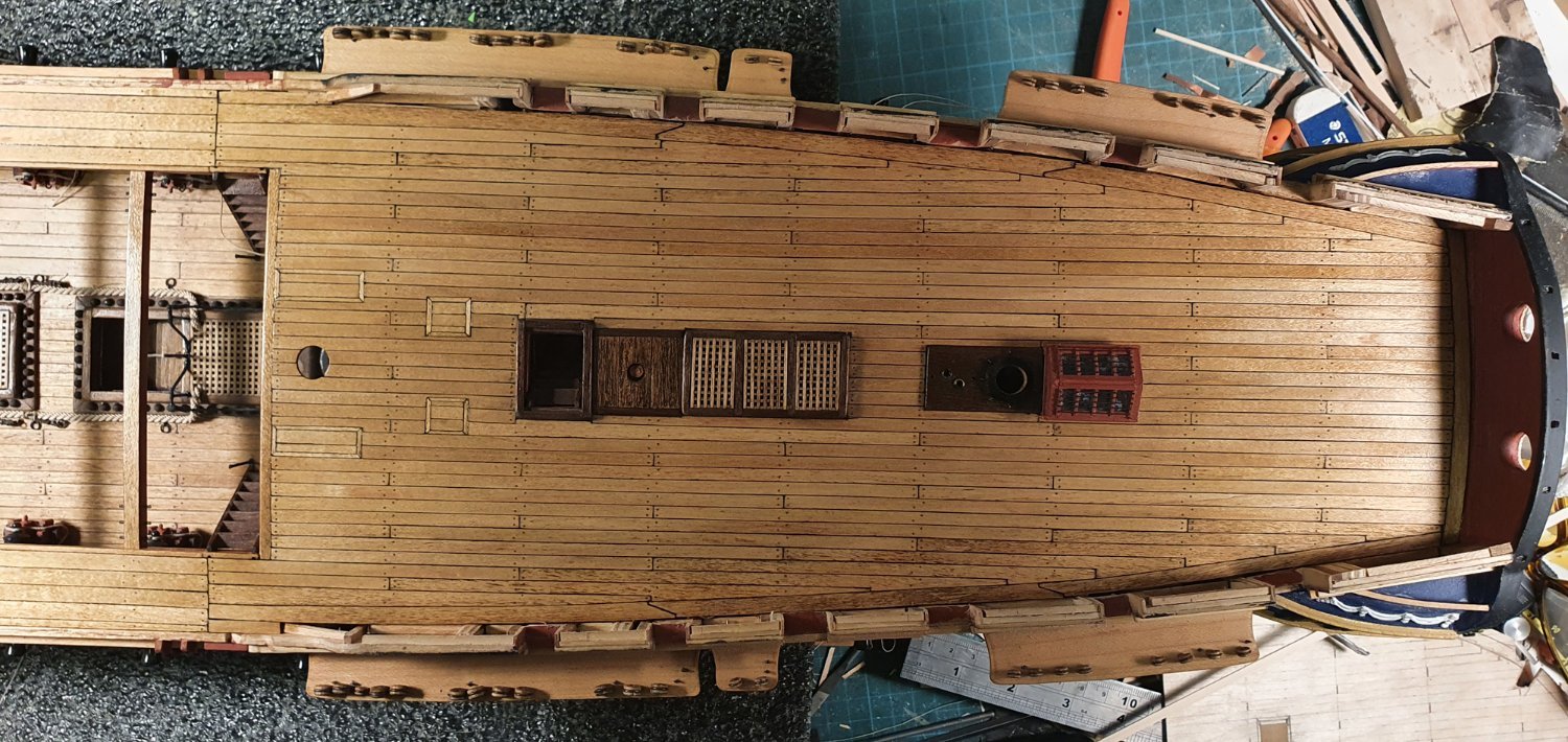
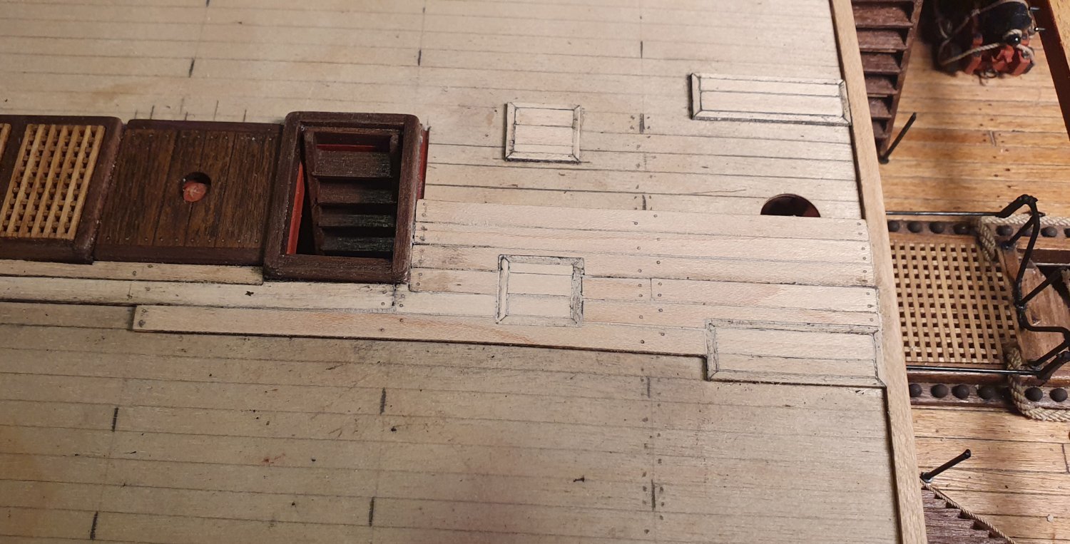
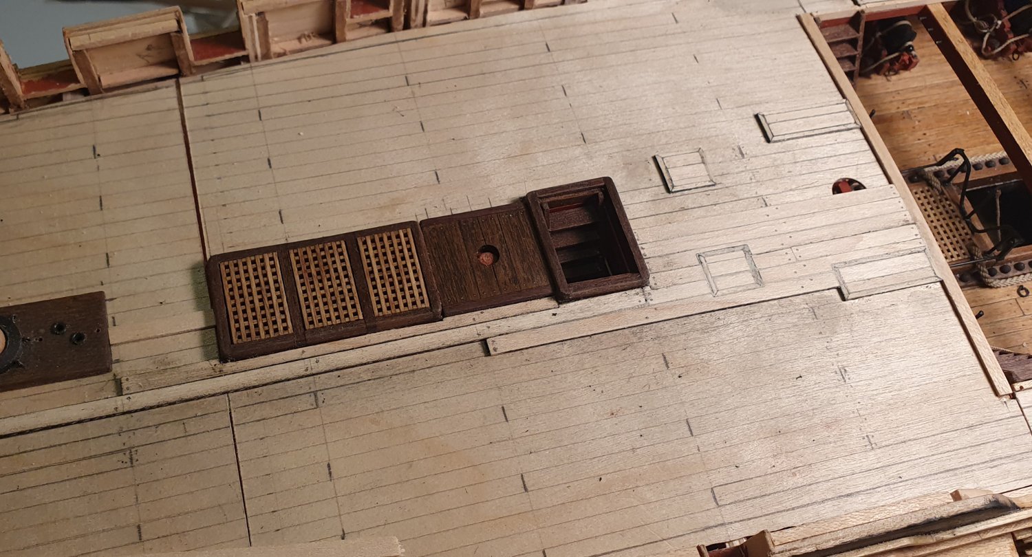
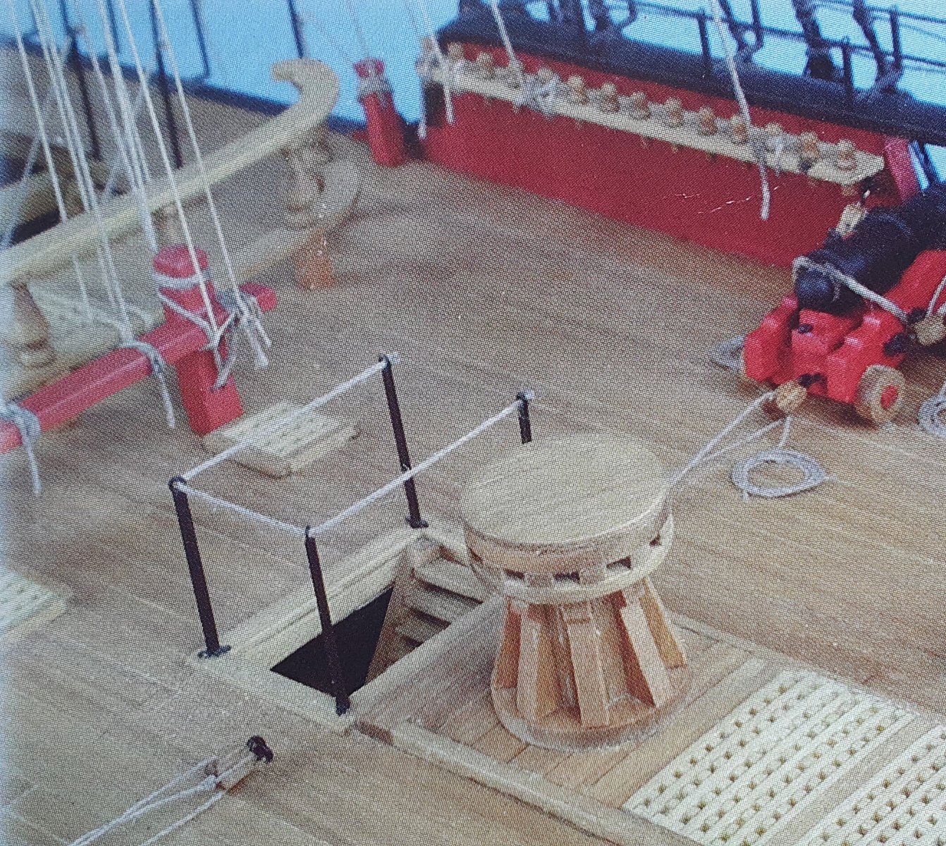
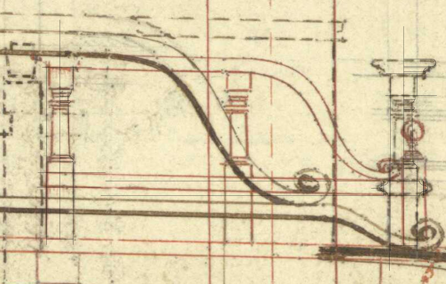
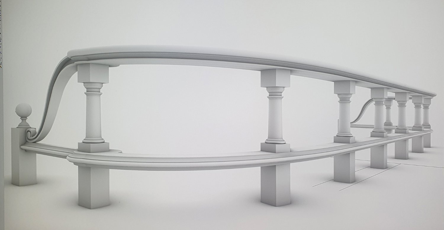
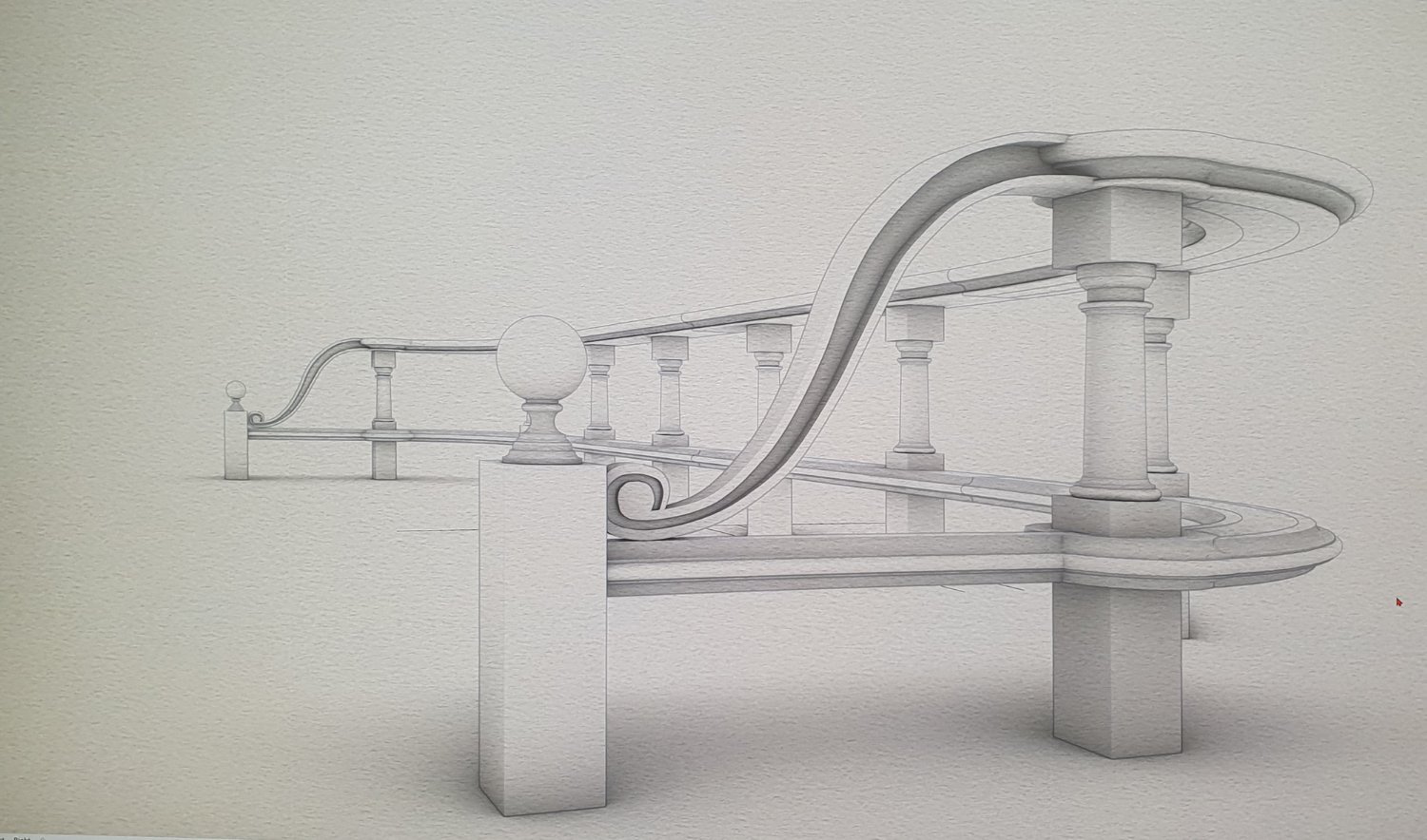
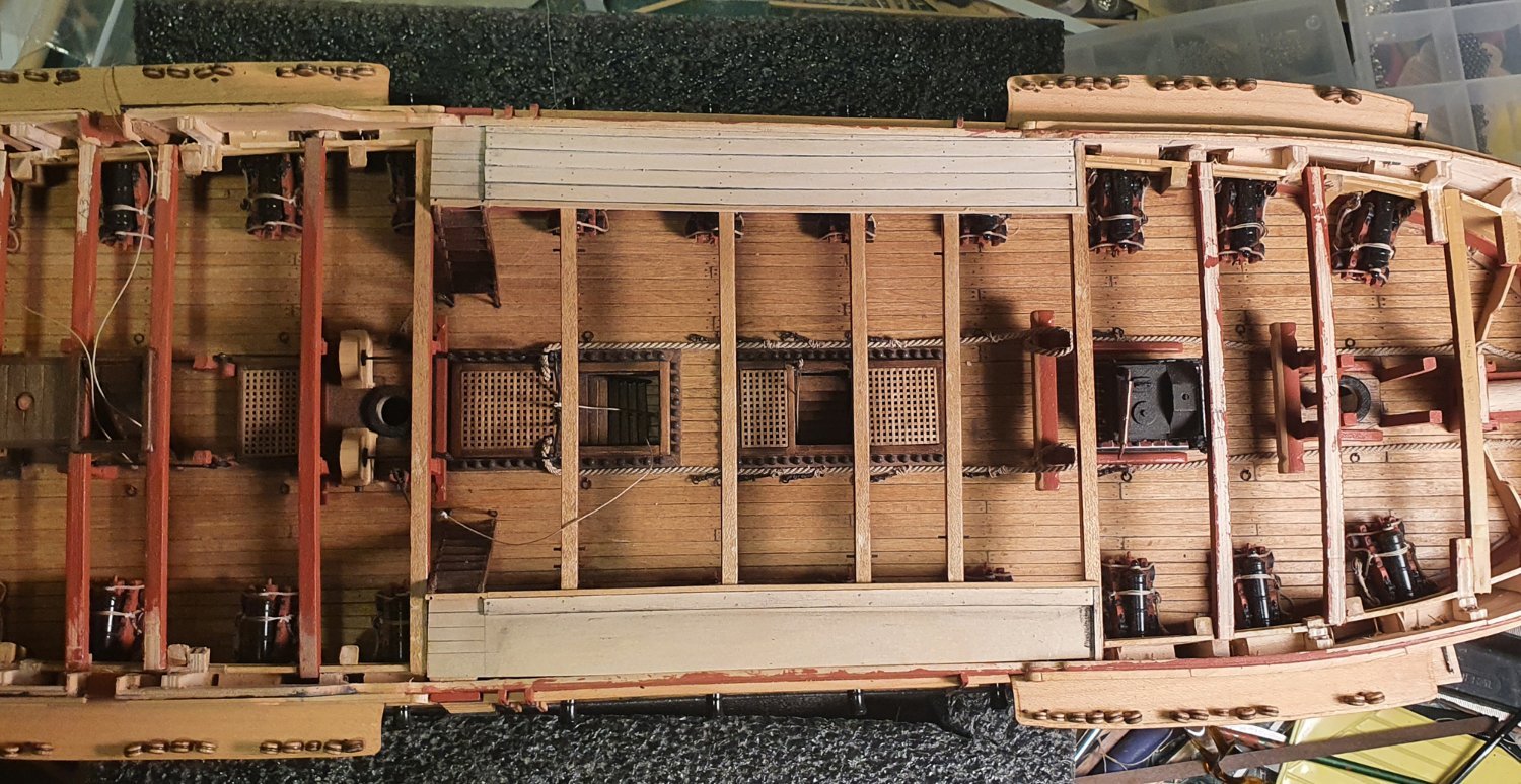
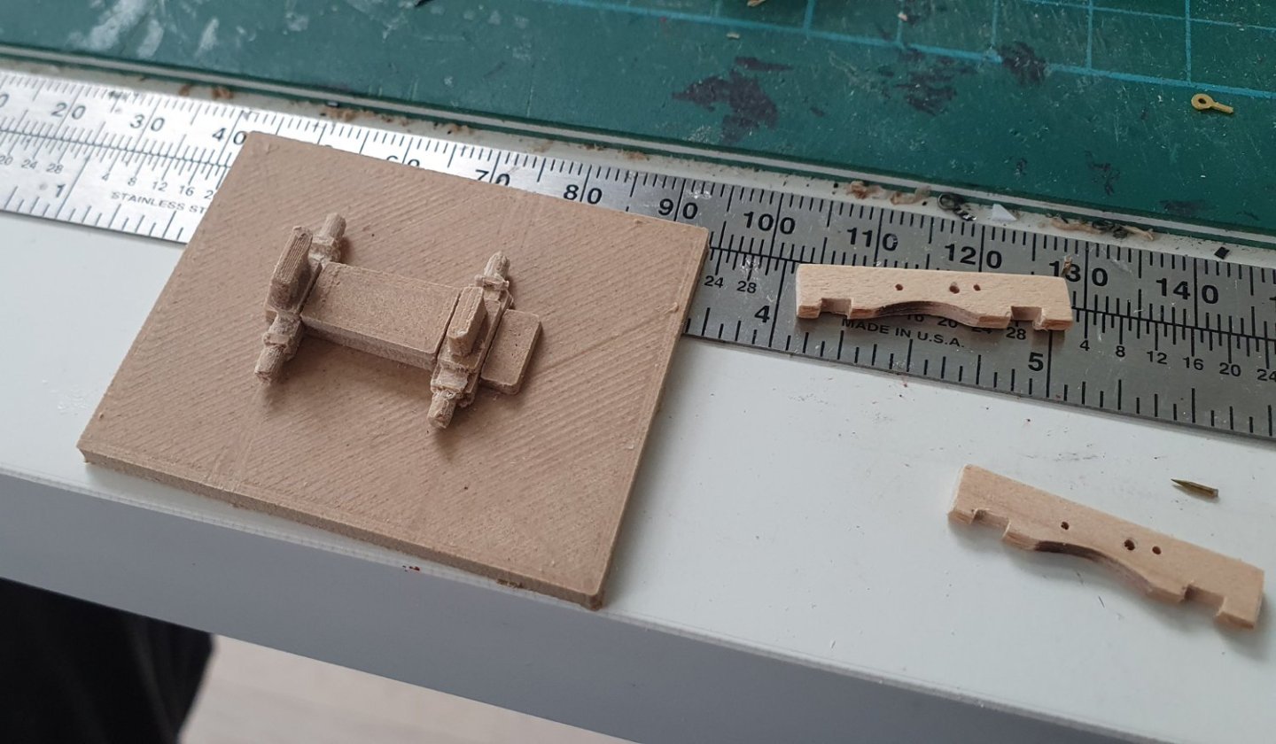
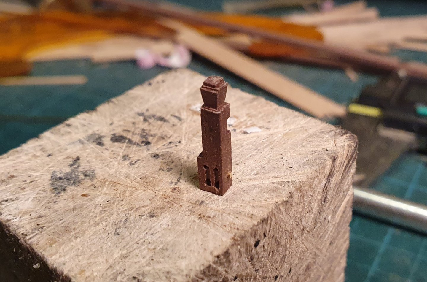
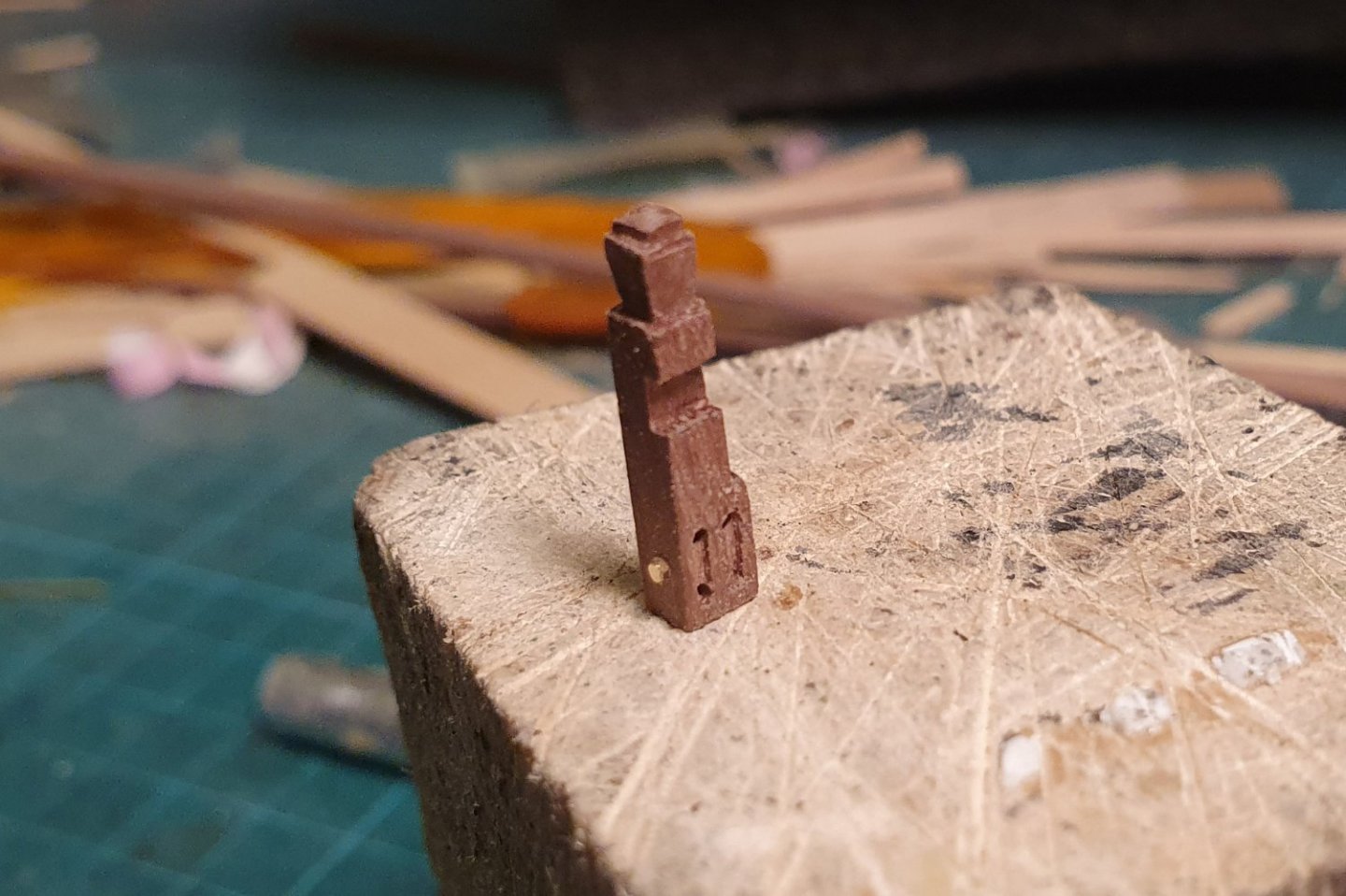
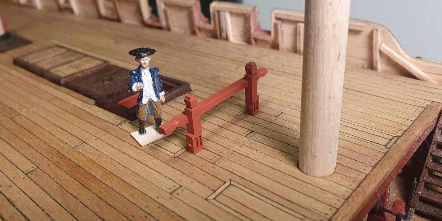
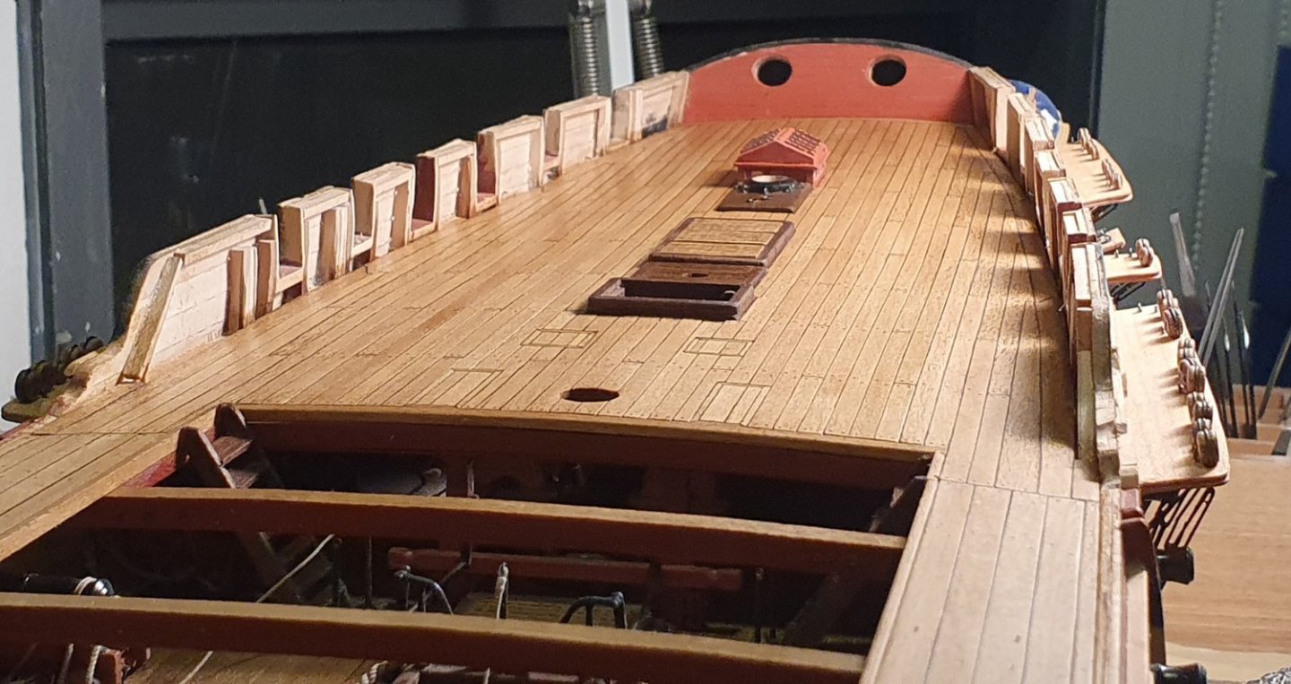
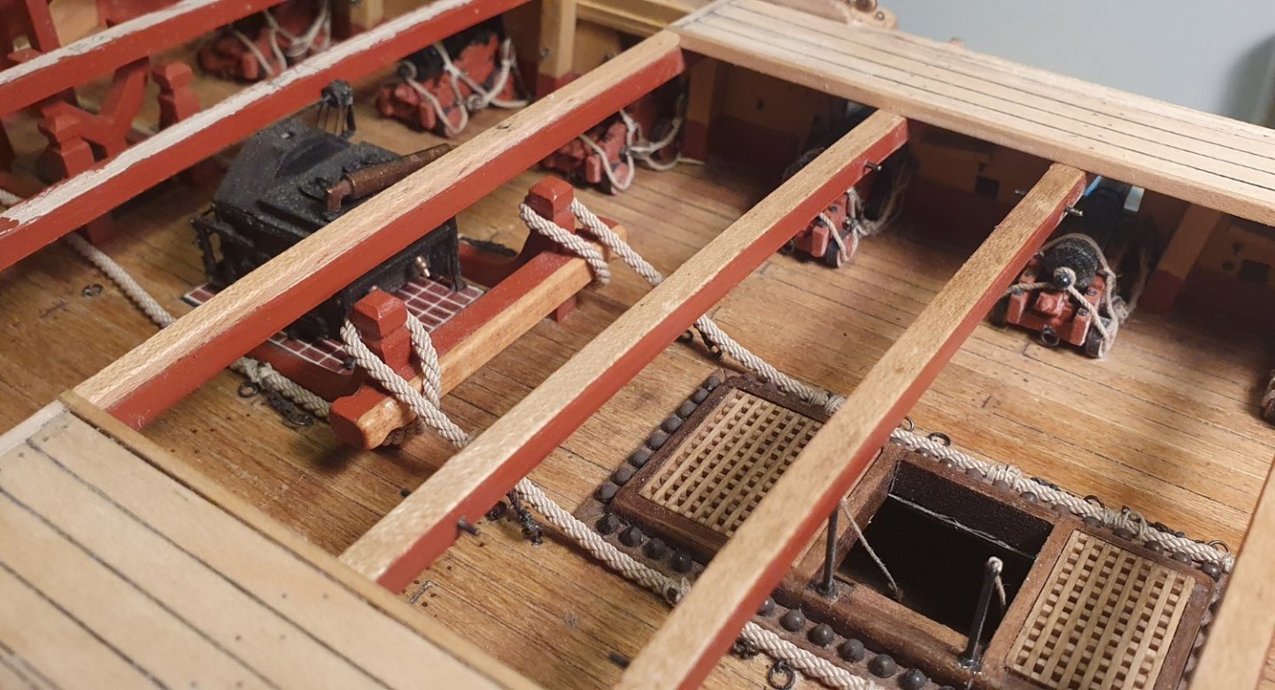
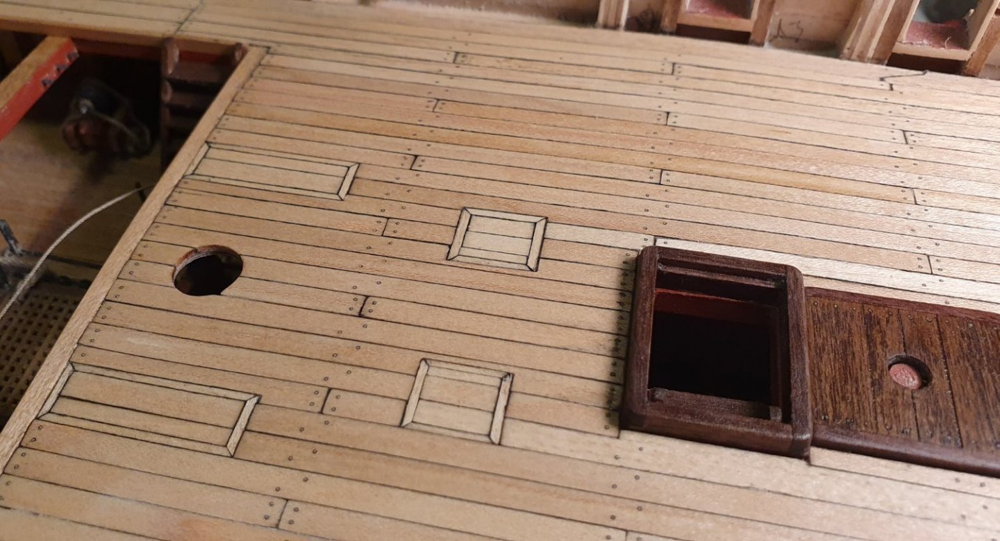
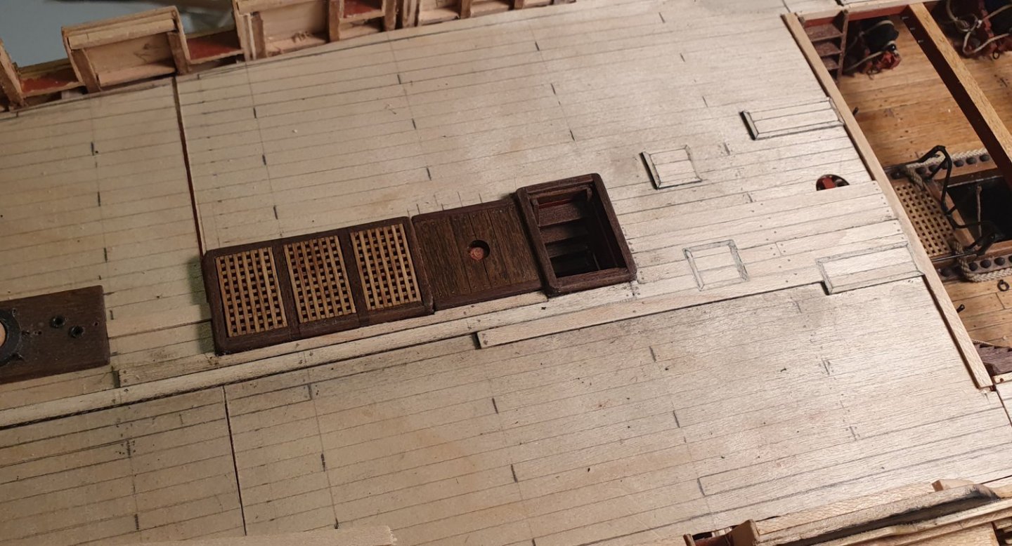
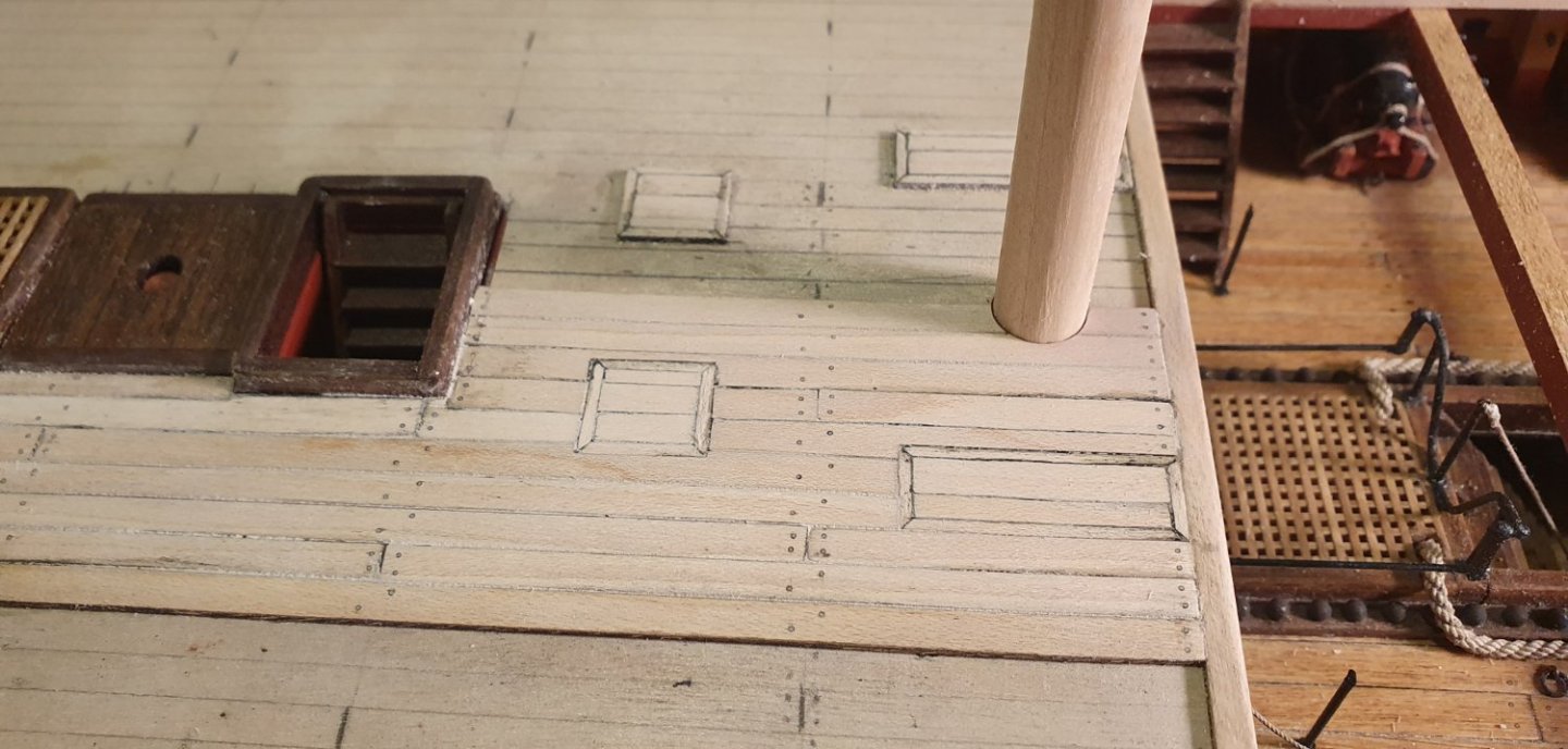
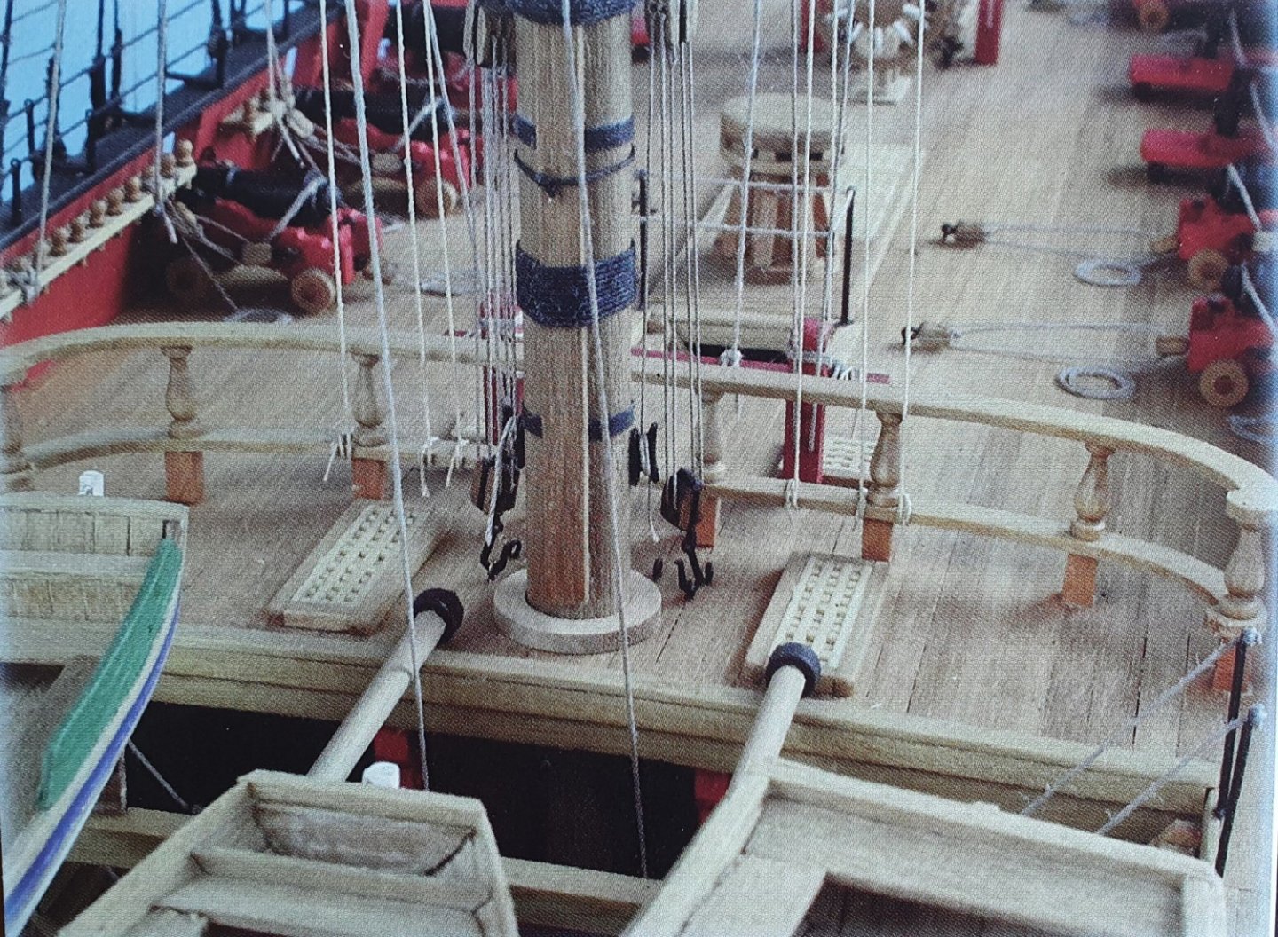
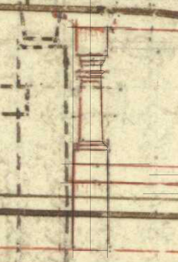
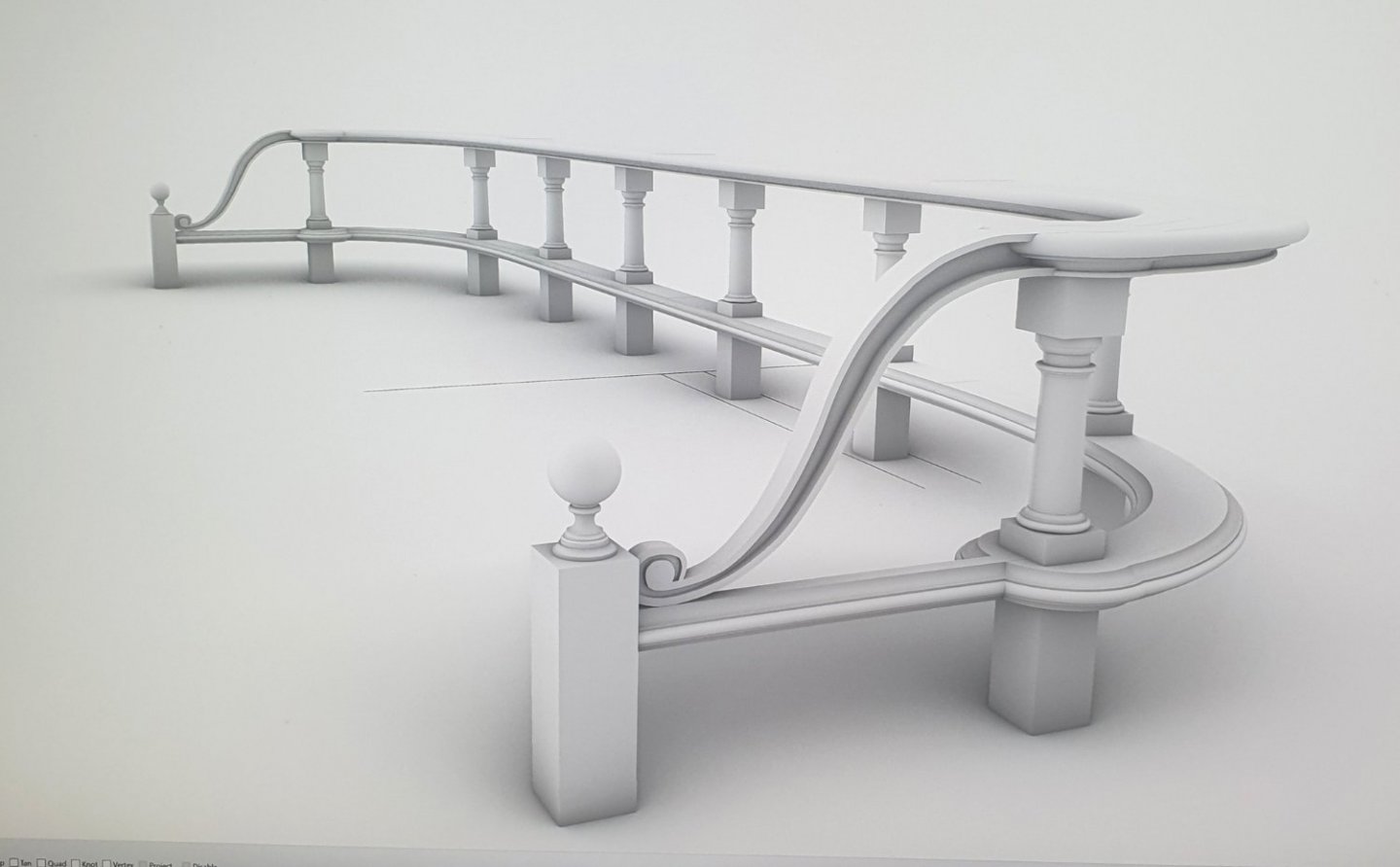
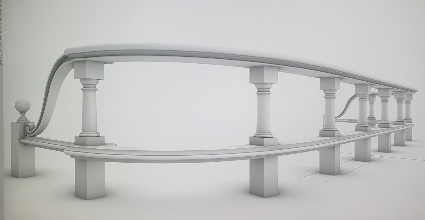
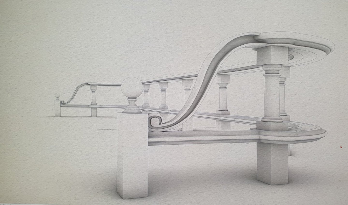
Started planking the quarterdeck with Maple. Slow work but quite therapeutic. As you can see I decided to set my scuttles flush with the deck without coamings. For a more vigorous discussion on the scuttle coaming dilemma you can refer to Dunnock's build so it needn't be repeated here. To give myself a break from the tedium of planking I started to investigate some of the other fixtures that are located on the quarterdeck. The kit supplied barricade that sits behind the main mast does not look that bad as one can see from the photograph shown on the box. The main difference from what is actually included in the kit is that the top and bottom rails are provided in walnut ply which would suggest that these will eventually have to be painted rather than have a natural wood finish. I had a look at the NMM drawings and this barricade is one of the fittings that is drawn in some detail. It is a bit fuzzy but with a modicum of artistic licence you can see that the balusters are not the bulbous vase form but resemble a truncated tuscan column. Of course it may be that the draughtsman had a classical bent but I think the drawing is probably closer to reality than the kit interpretation. The barricade also extends to the quarterdeck breast beam with an elaborate scroll and terminates in an ornate newel post. This detail is also present in the contemporary models. How this scroll joins to the top rail is quite ambiguous as is the detail of the bottom rail extension. To get a visualisation of this I knocked up a rough and ready CAD model based on the NMM drawings but I fear that I may have to resort to the kit supplied pieces as I do not think I can incorporate all of that detail at a scale of 1:64. I may waste an afternoon giving it a bash though.


-
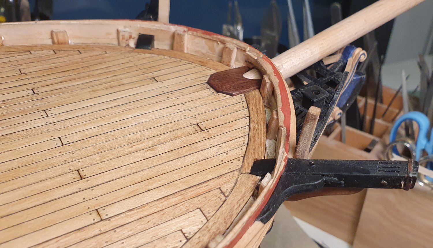
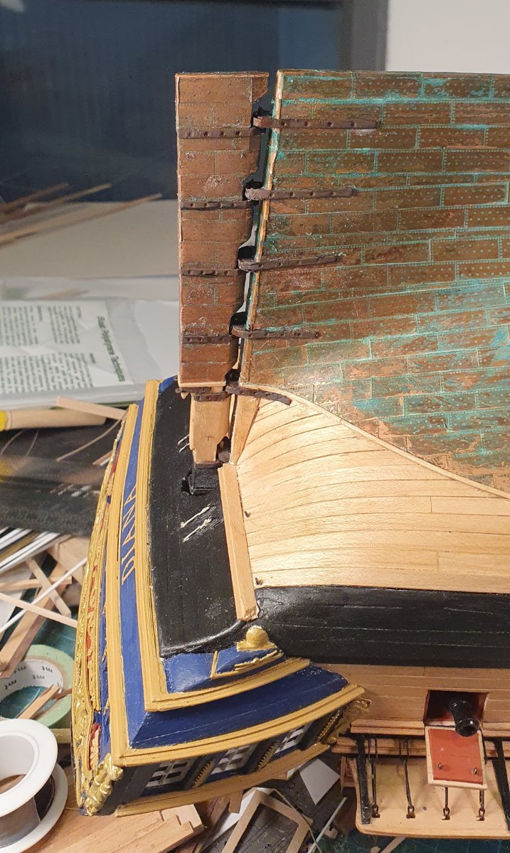
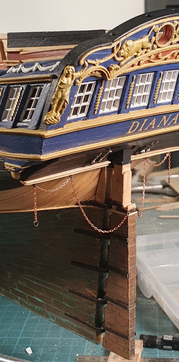
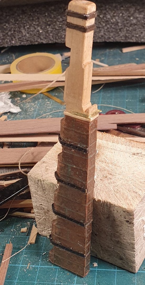
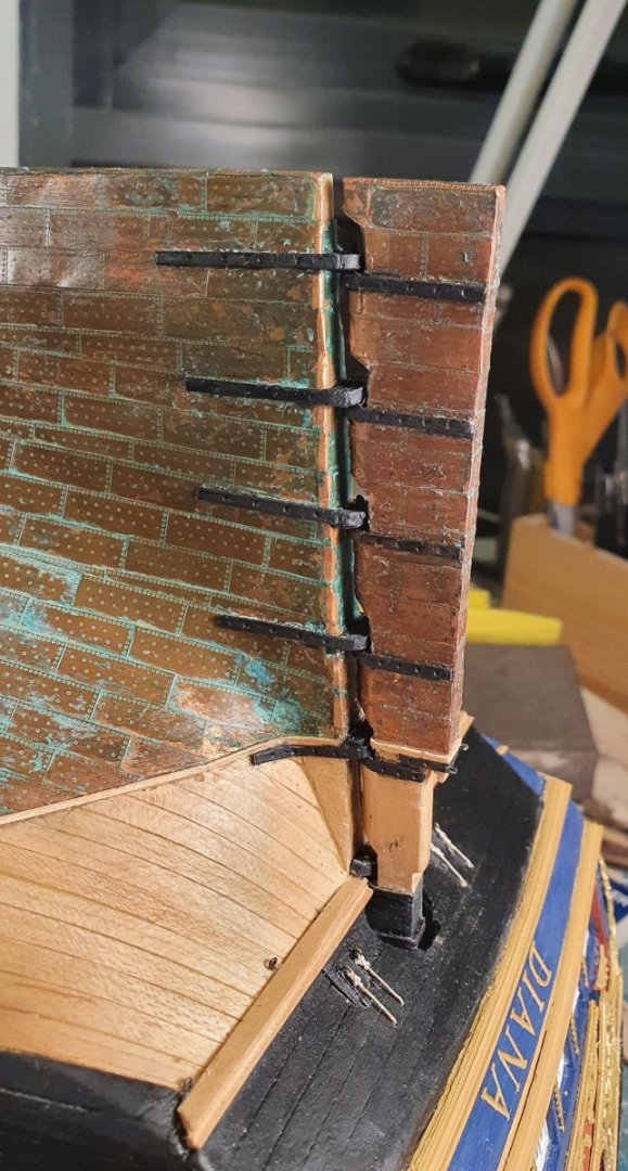
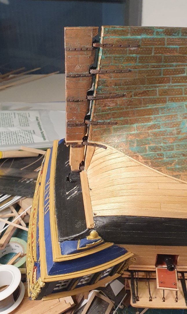
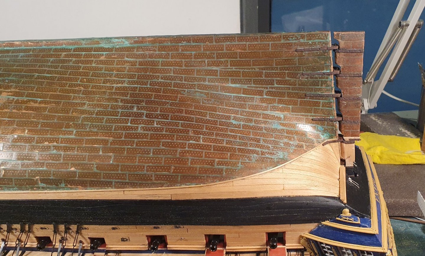
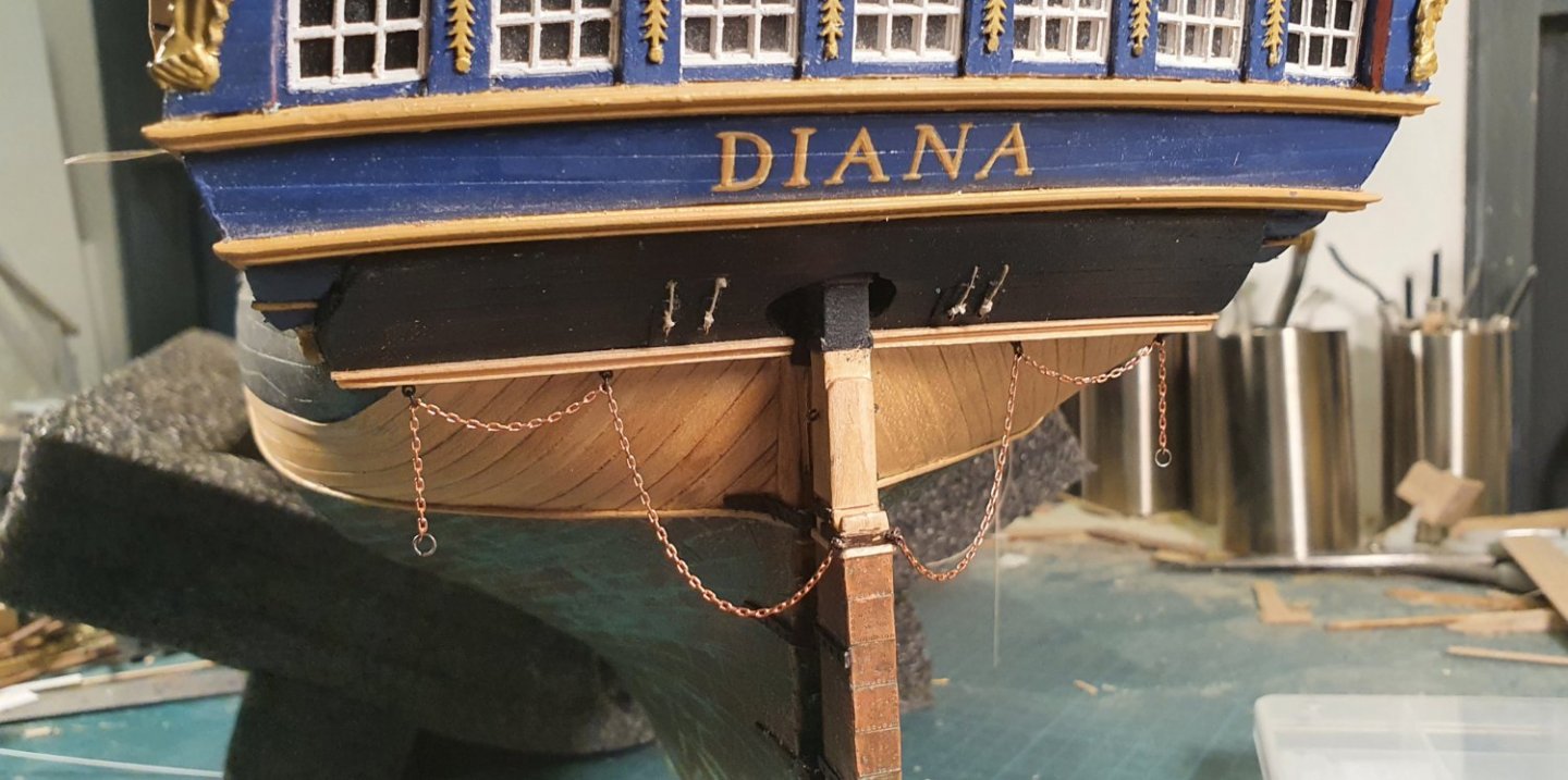
A somewhat frustrating week of modelling trying to fix the rudder. It all ended in tears with a spectacularly bungled effort as a result. The profile of my stern post was all wrong and I had waited too far into the build to start the installation so there was no real opportunity for the major remedial work required. The unmatched stern and rudder profiles meant that I had to fashion new pintles and gudgeons out of styrene and brass rod. This resulted in the gap between the rudder and the stern post being too wide. I thought about tearing the whole thing down and starting from scratch but I decided that I would just live with it. I went to install the rudder chains but I could not find the kit supplied chain. I remember seeing it but do not know where it has ended up. Luckily my previous build had a lot of chain rigging so I had a fair selection to choose a replacement from. I still have to darken this. I am working out how to do the darkening while the chain is still on the model as fixing it in place was a big headache that I want to avoid repeating.


-
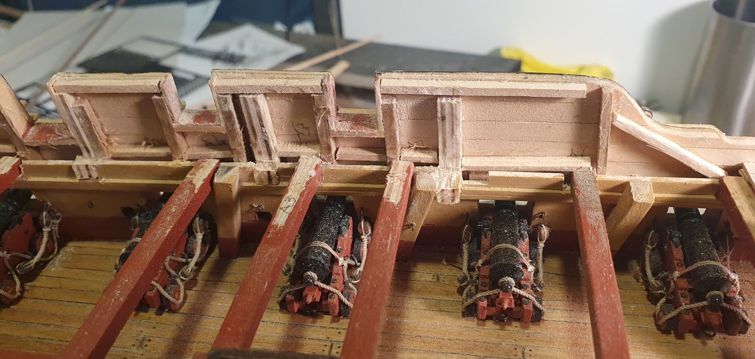
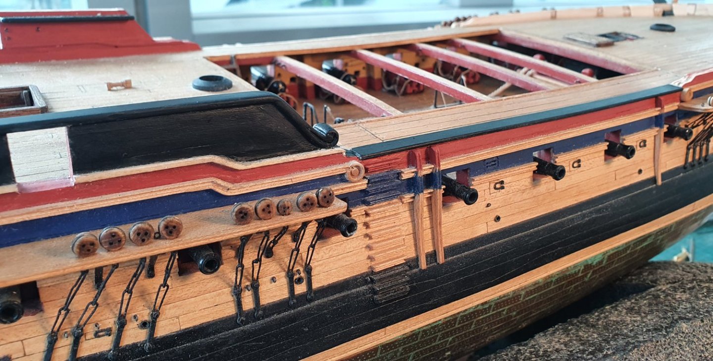
I have now caught up to my current build state so the posts going forward will no doubt become sporadic. This post is just a cautionary tale for those proceeding down the closed bulwark route. The kit bulwark frames above the quarterdeck are slightly too deep, in the wrong place and there are not enough of them to provide adequate framing for the gunports. I introduced some secondary framework to compensate for this but neglected to do any fairing until I had installed all of the gundeck fittings and quarterdeck beams. This was a mistake as I now have very little room to manoeuvre the Dremel and I have already knocked two cannons loose from their moorings while struggling to achieve the desired profile. The lesson to be learnt is that this should have been tackled much earlier in the build.


-
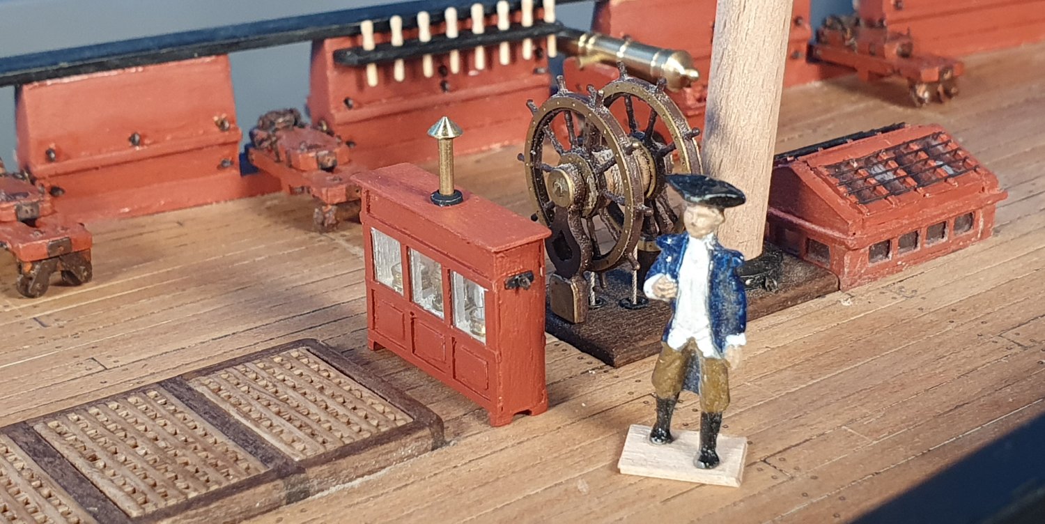
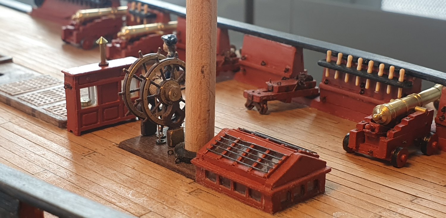
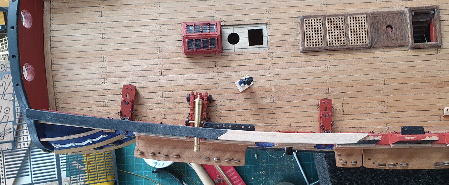
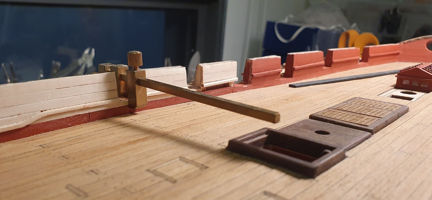
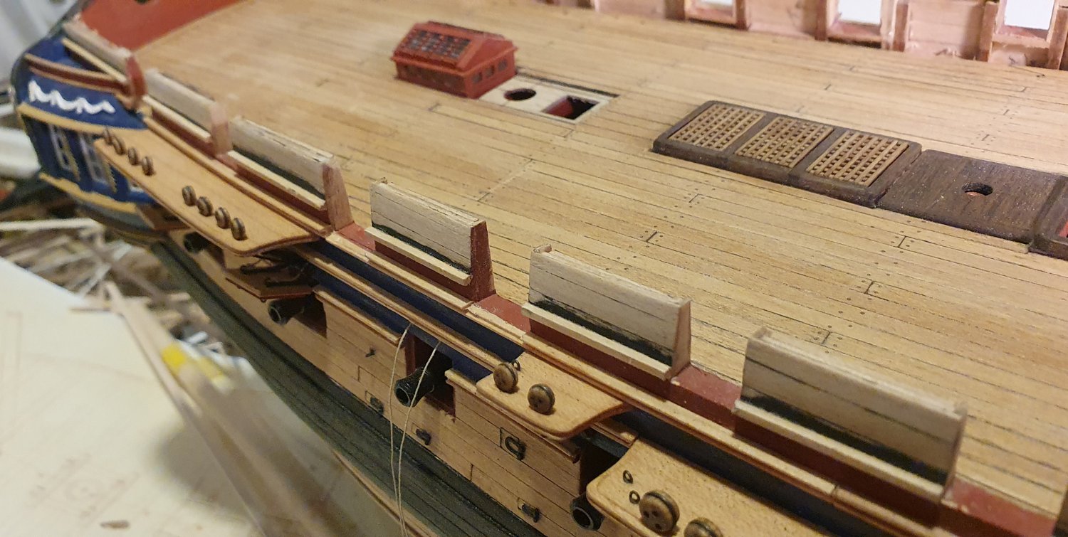
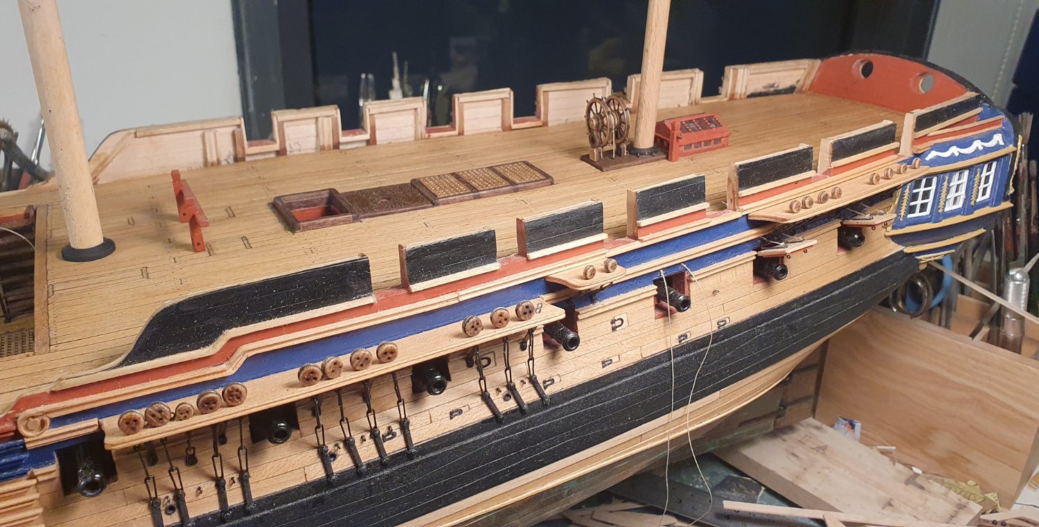
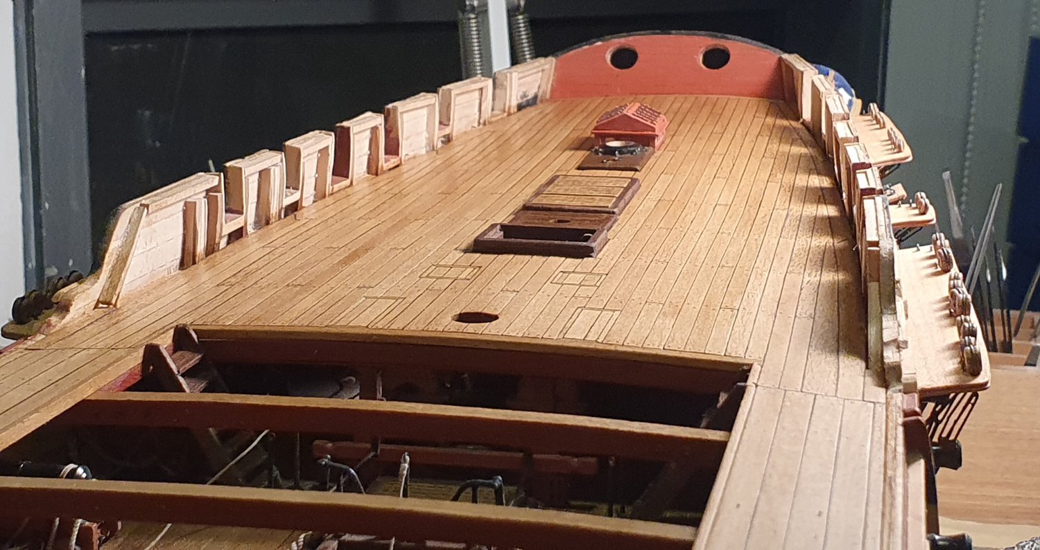
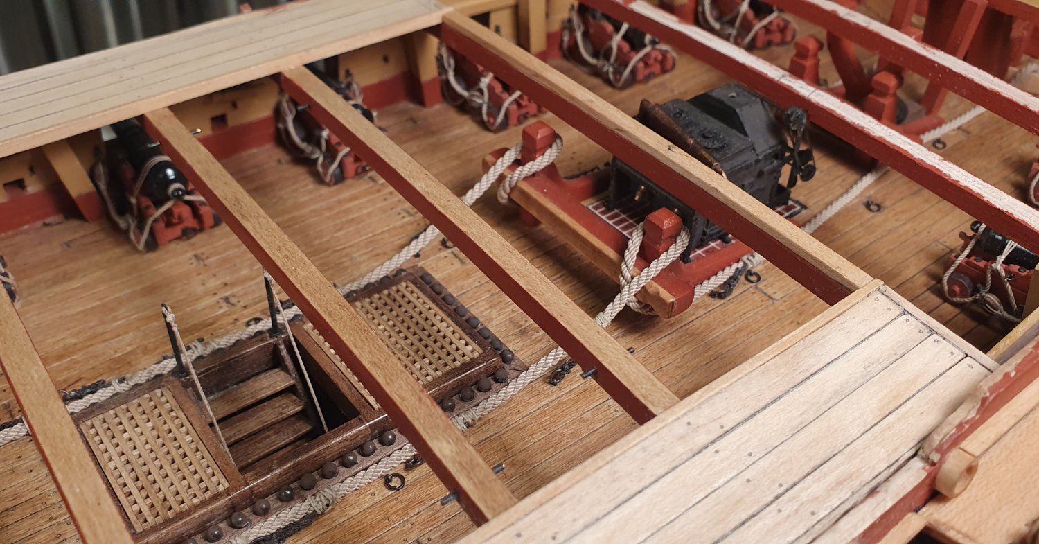
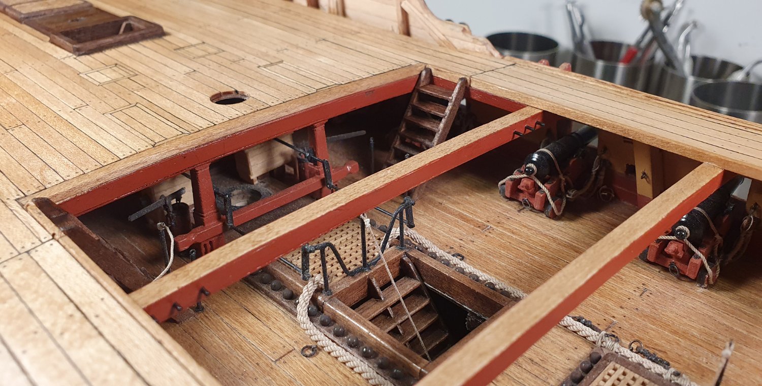
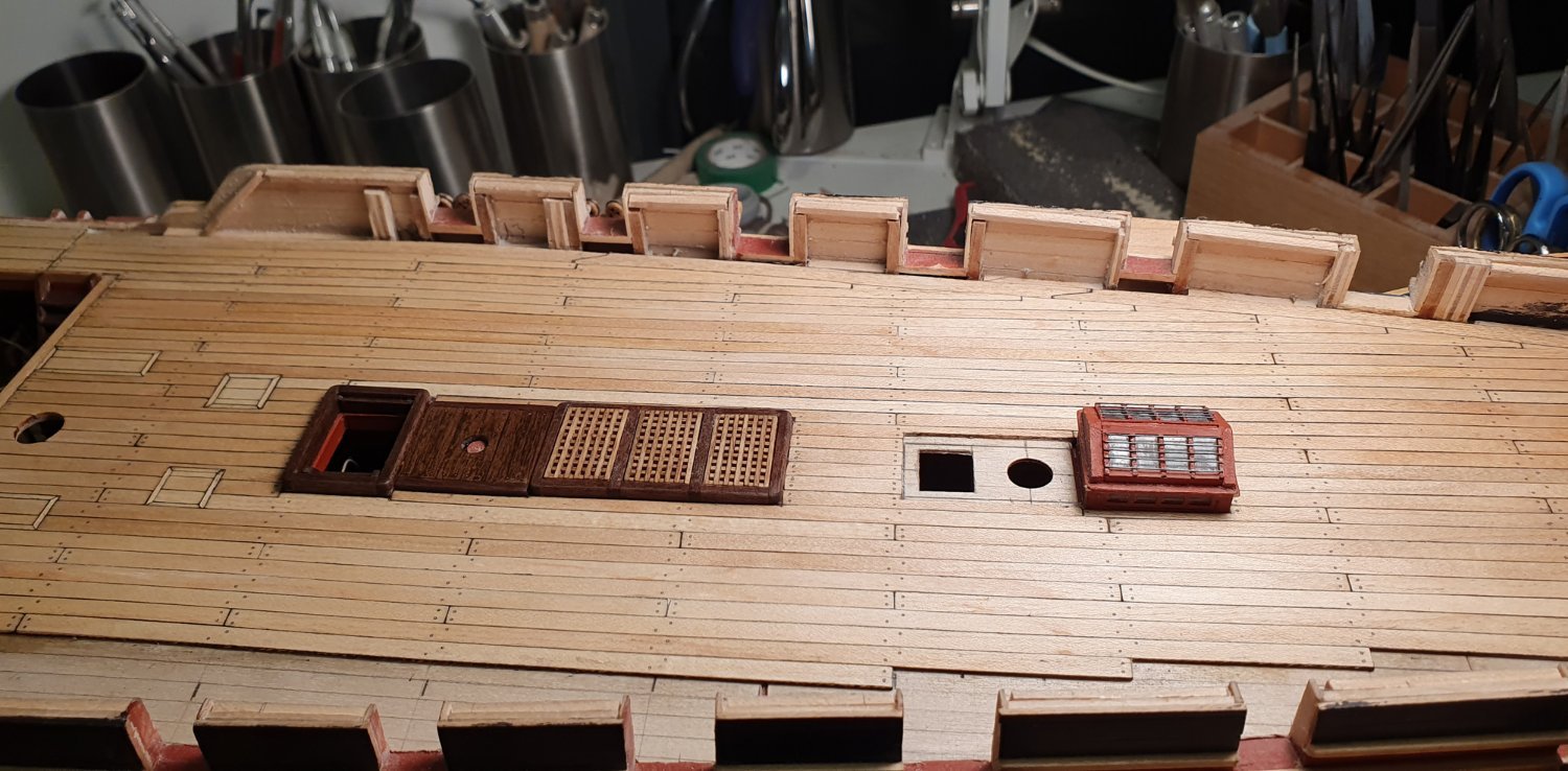
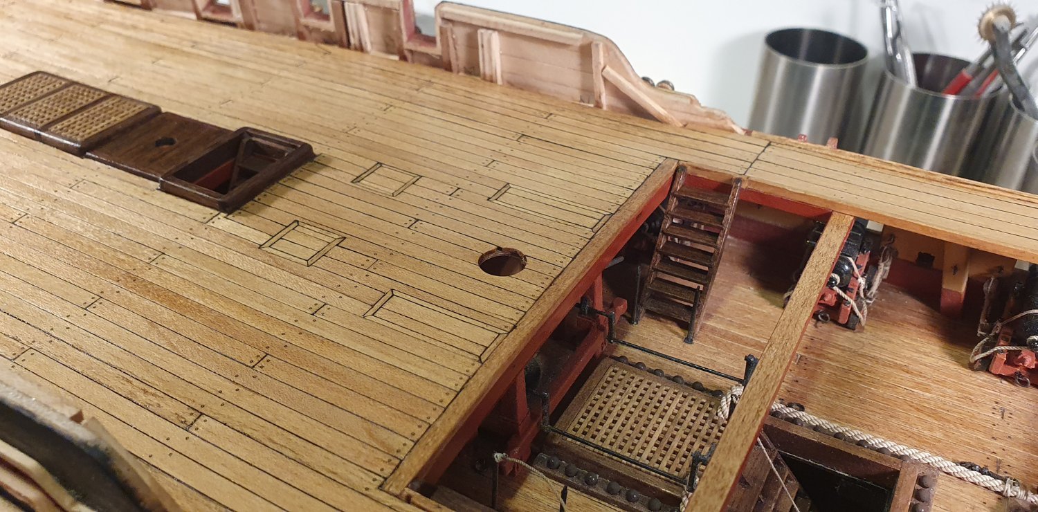
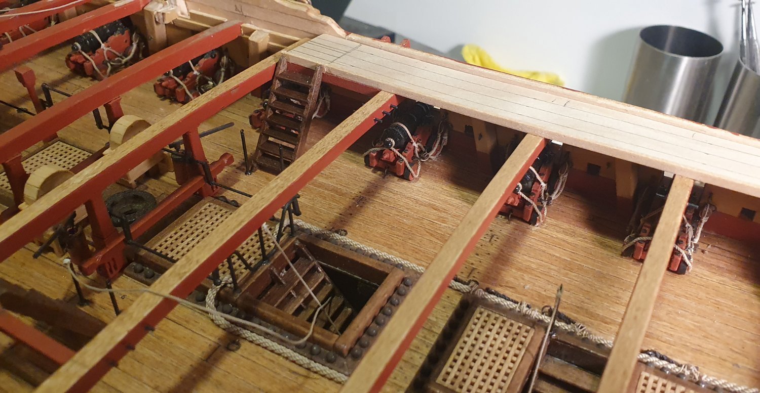
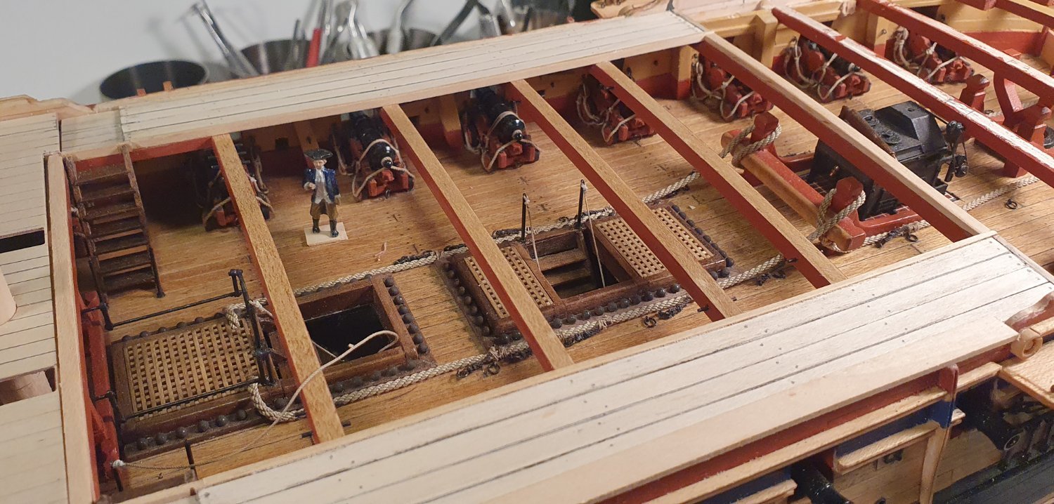
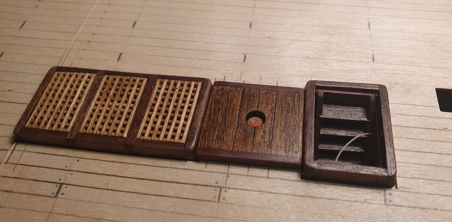
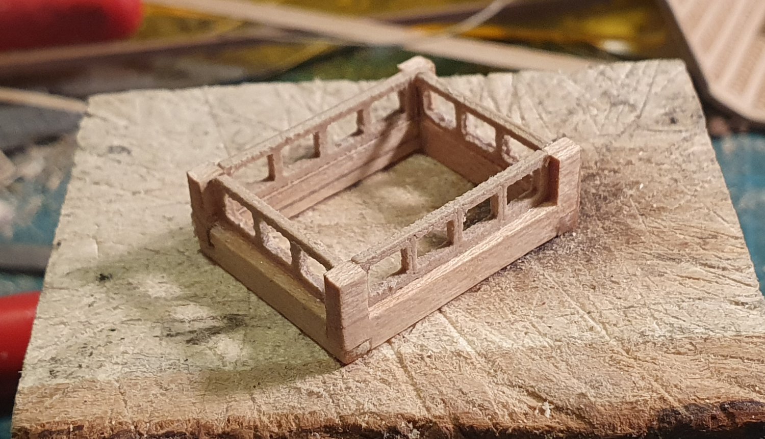
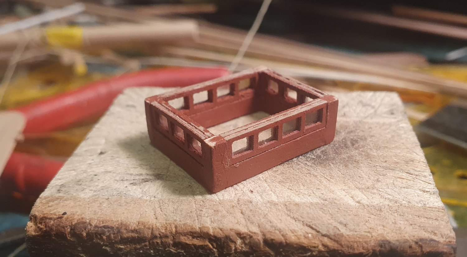
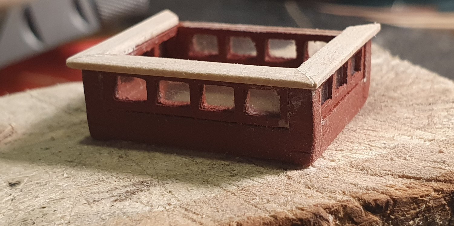
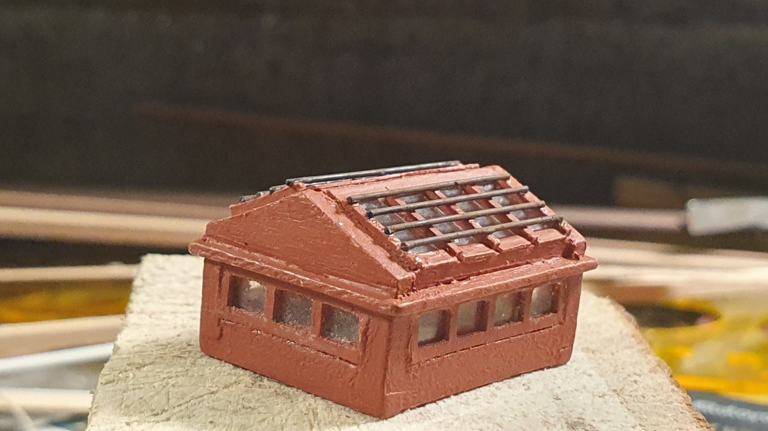
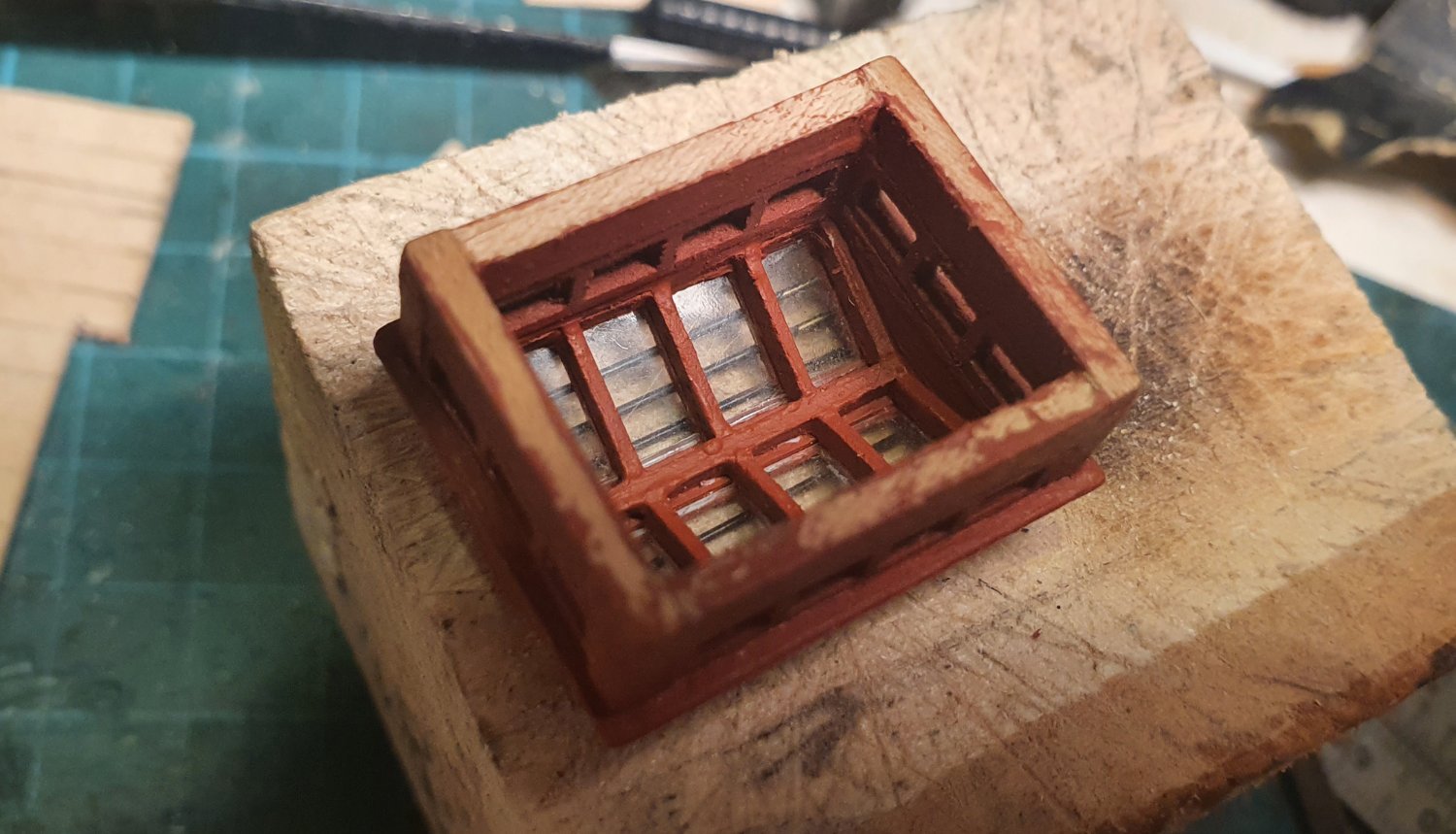
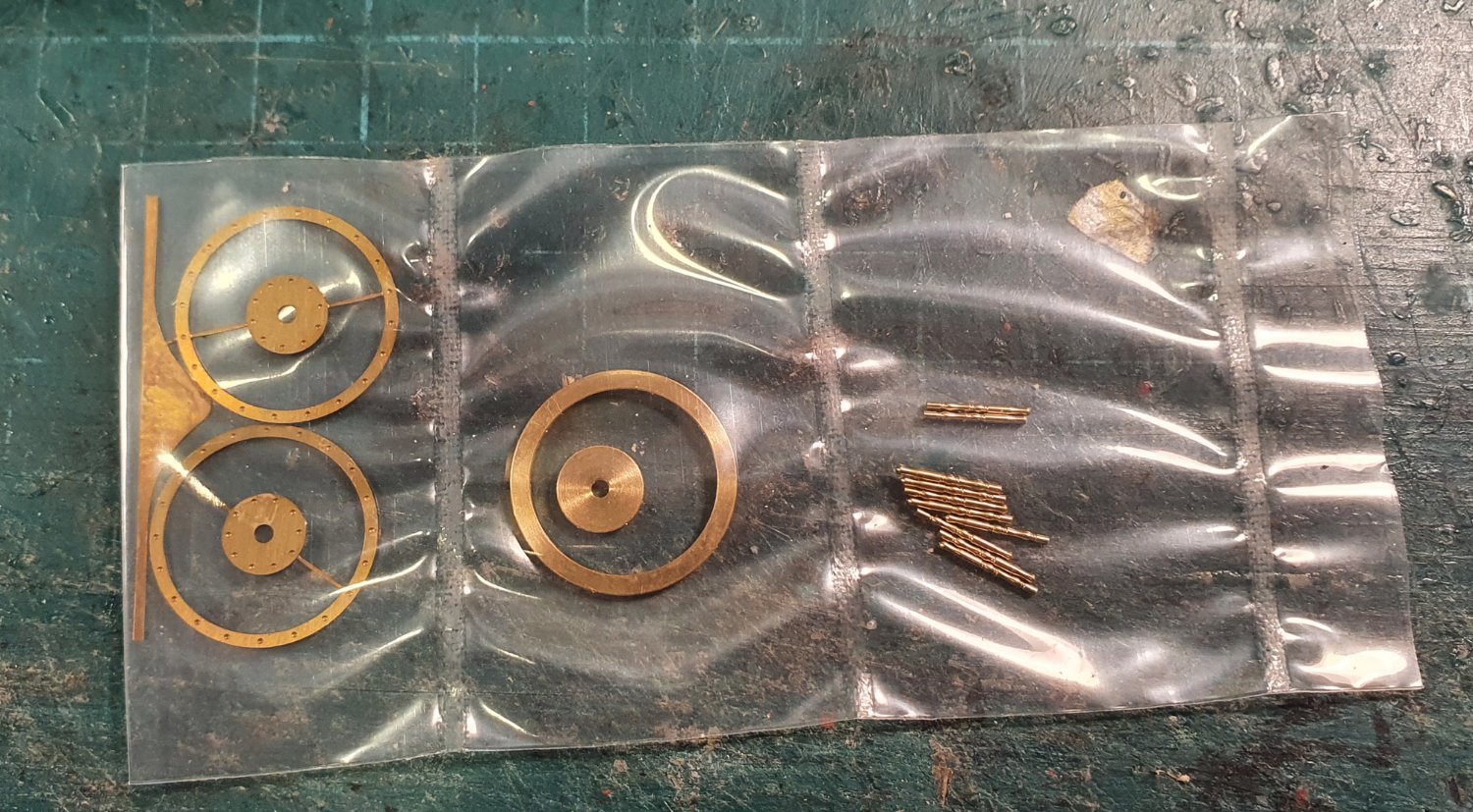
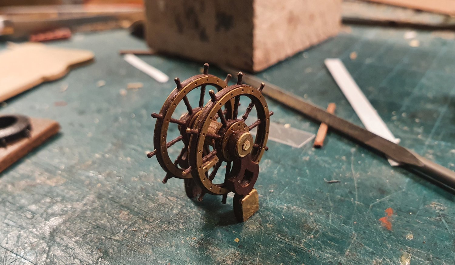
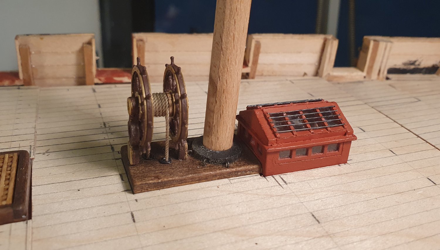
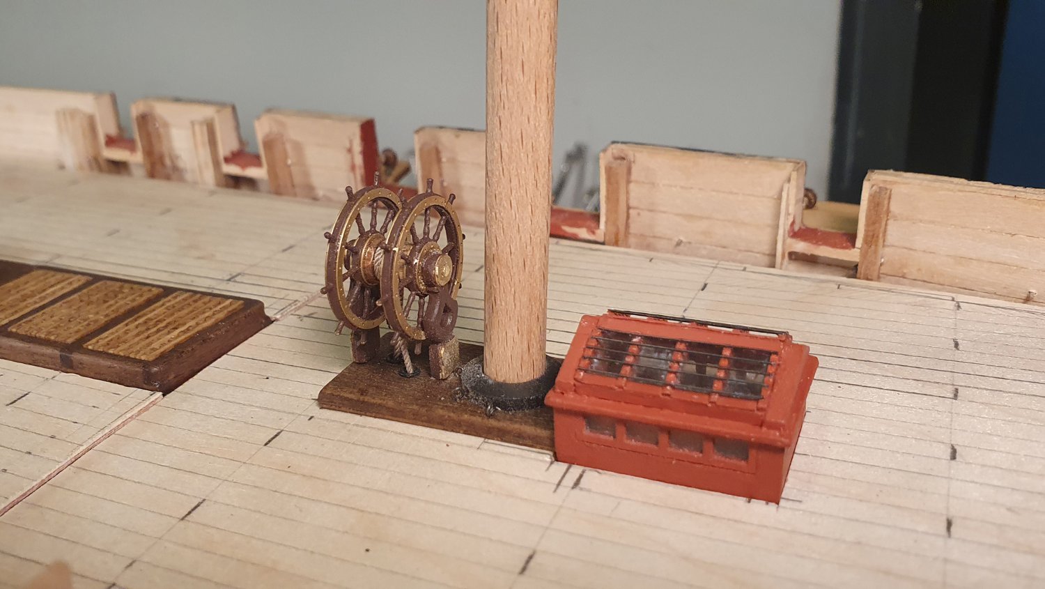
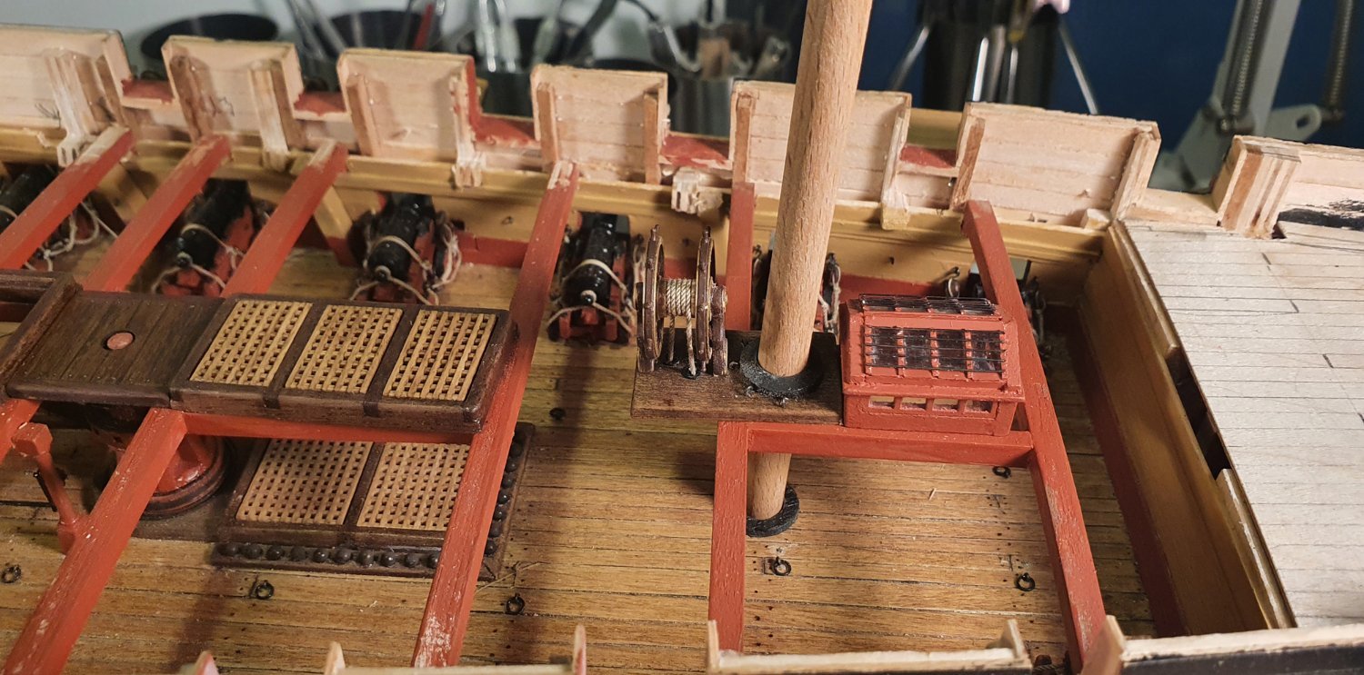
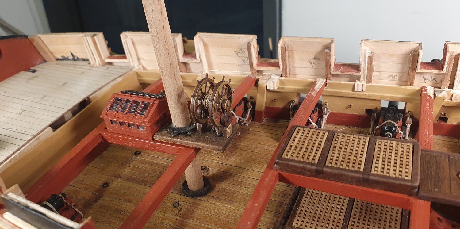
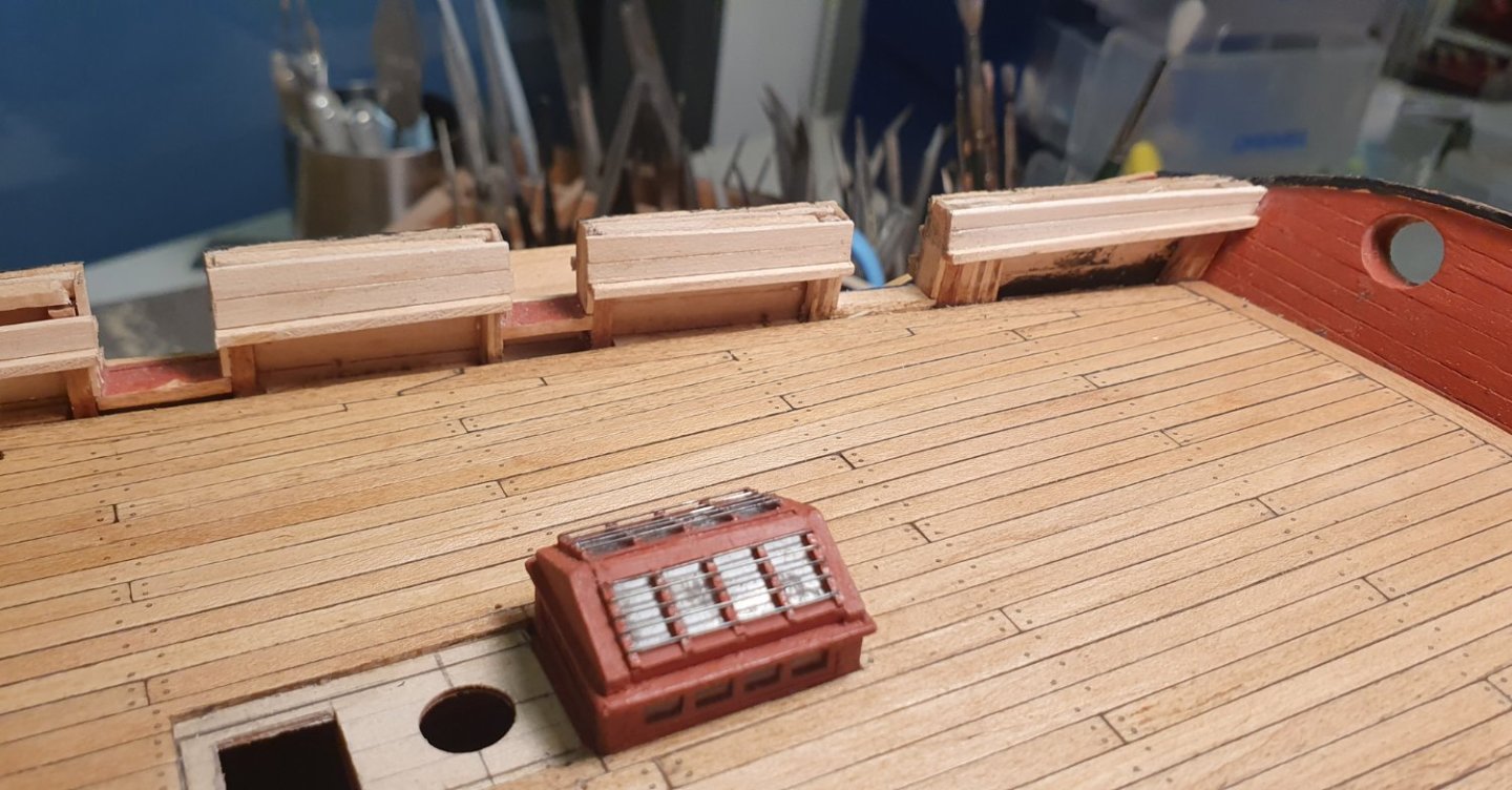
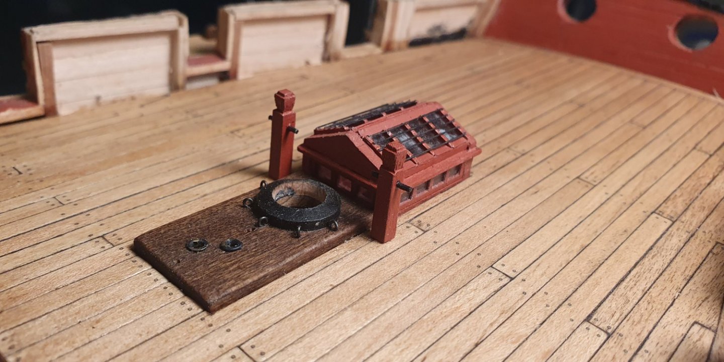
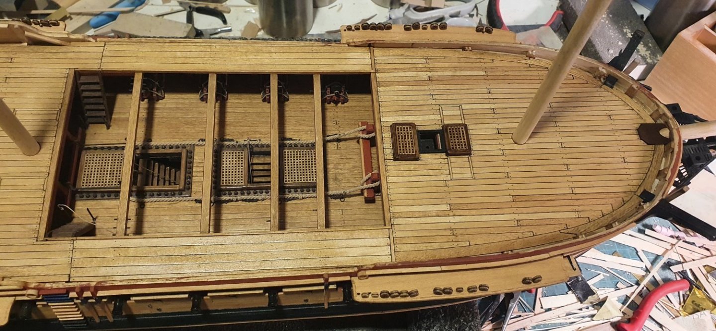
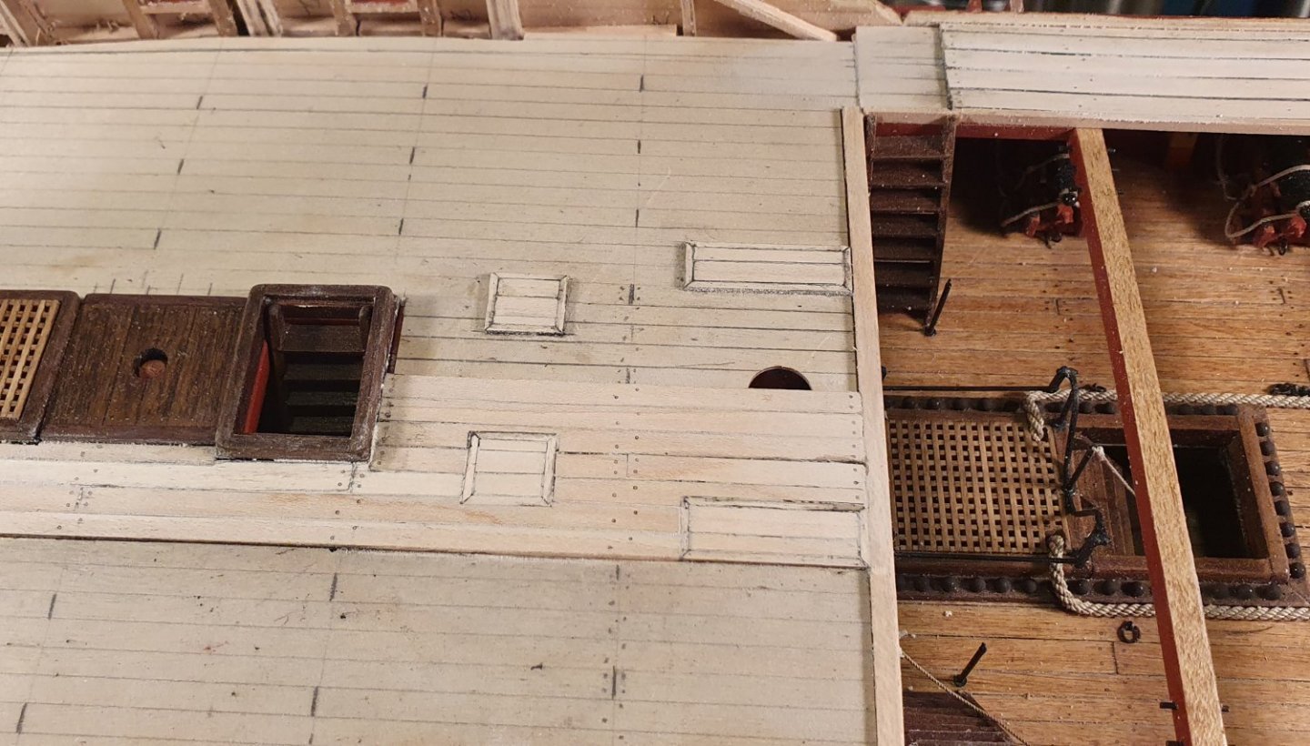
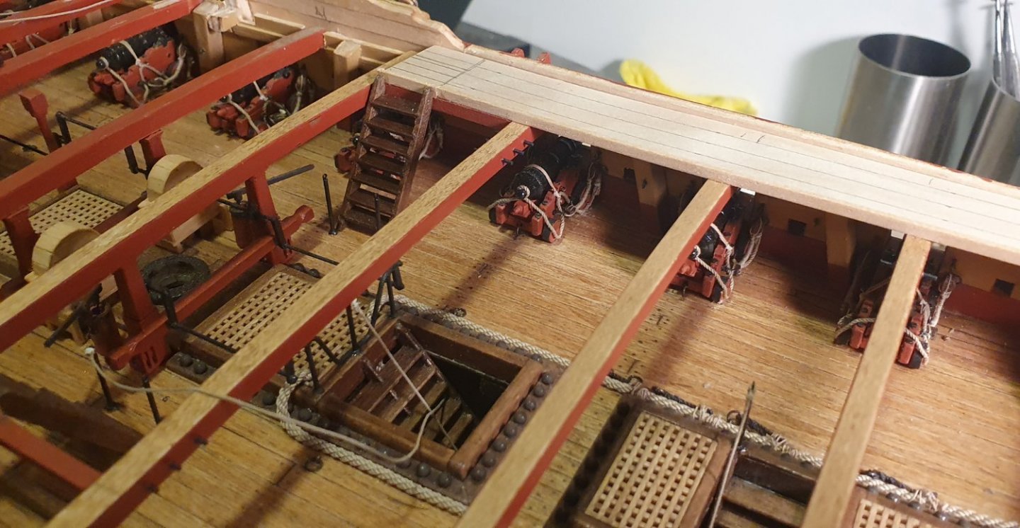
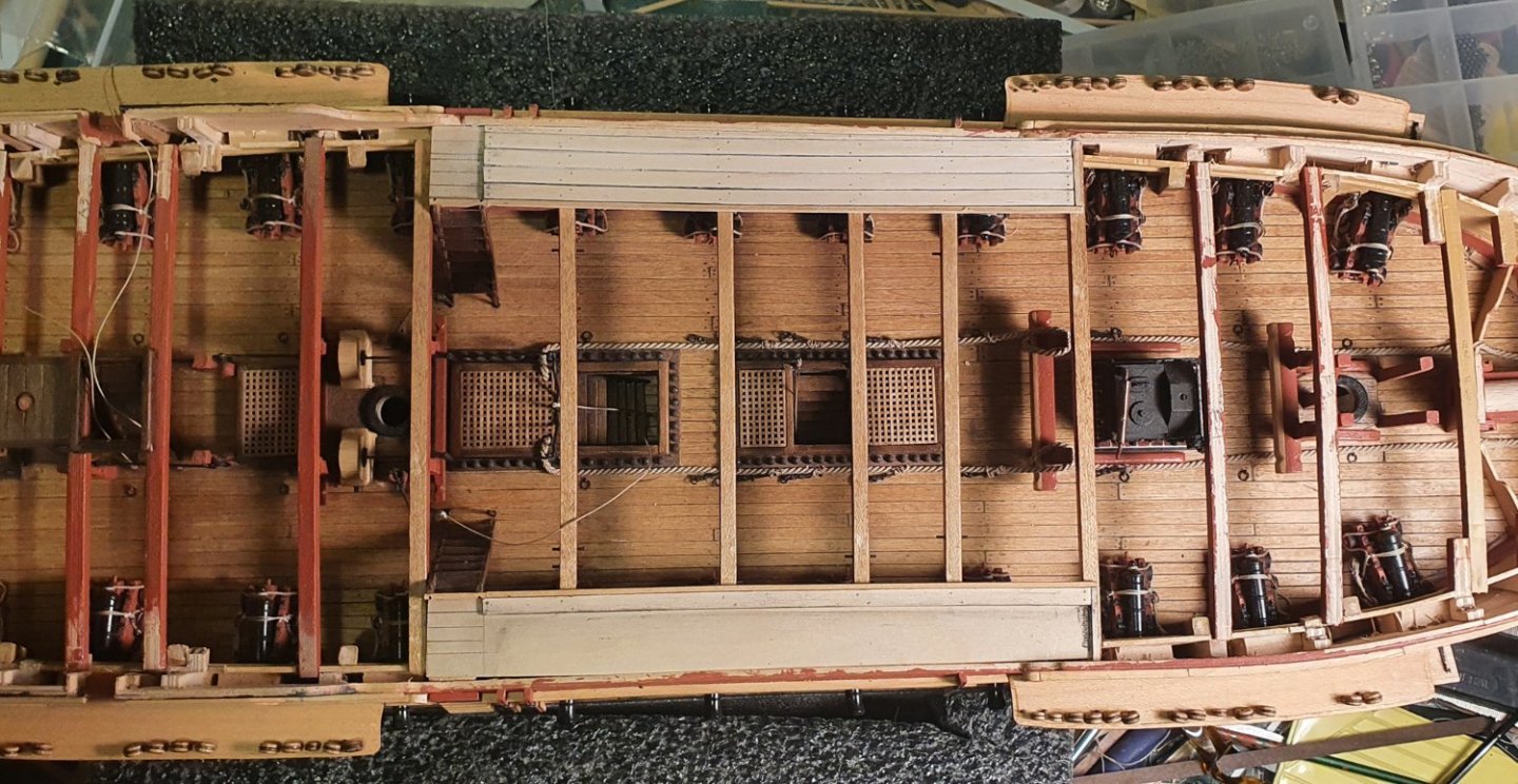
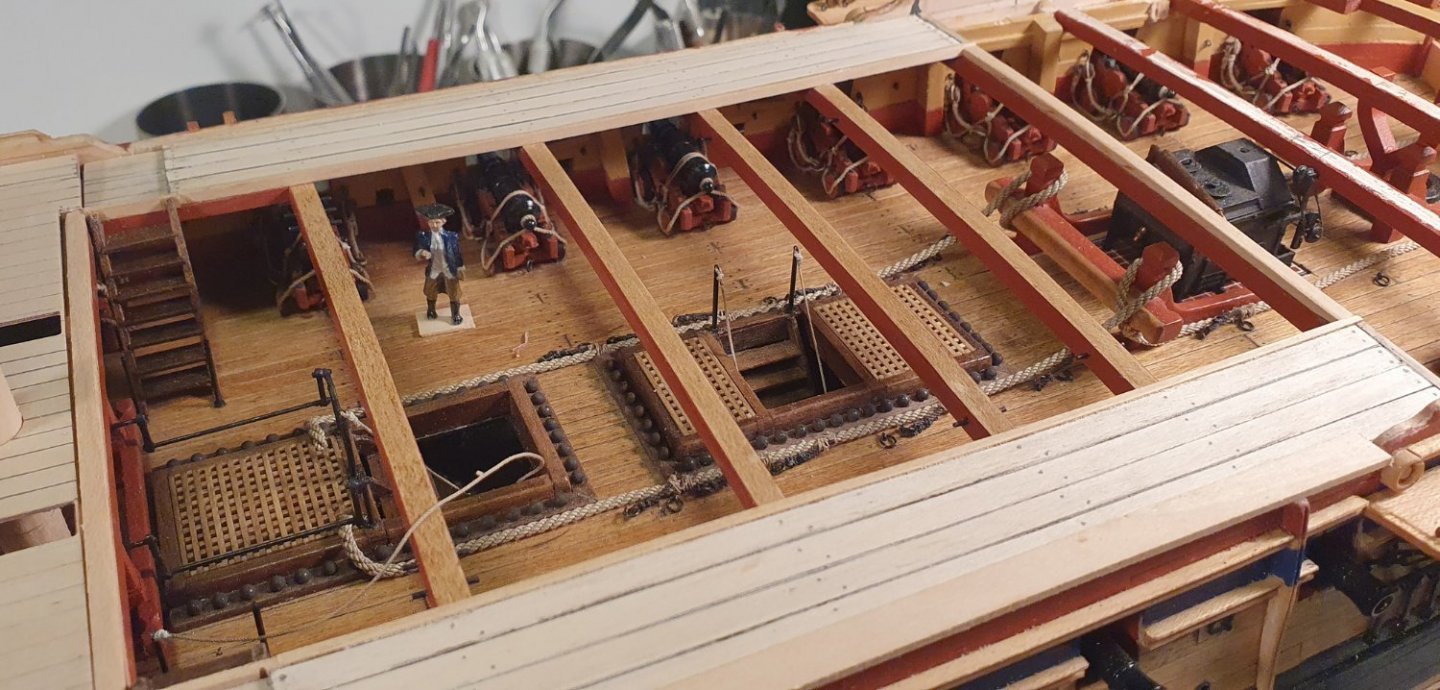
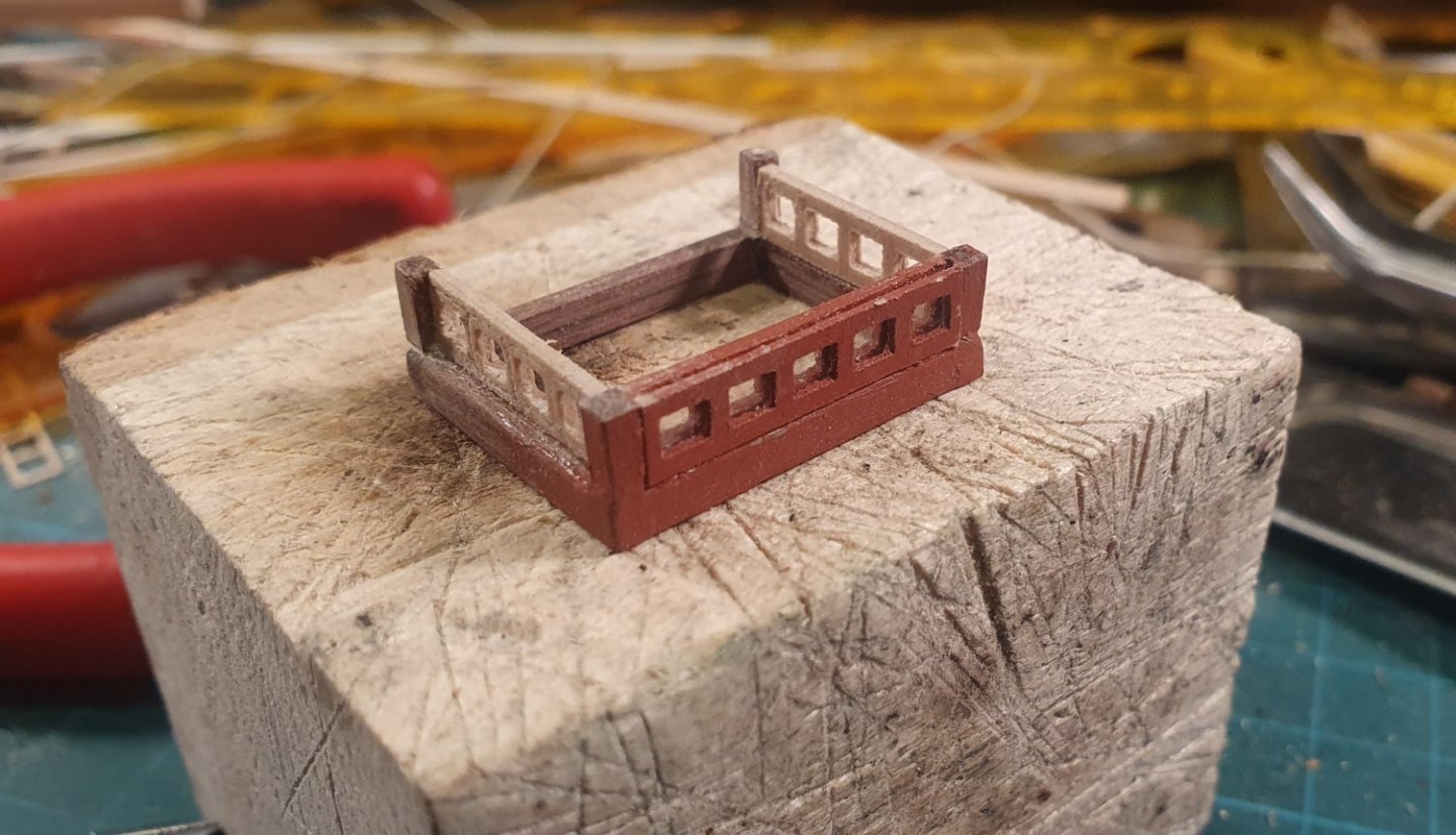
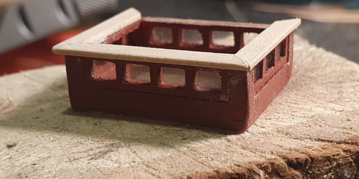
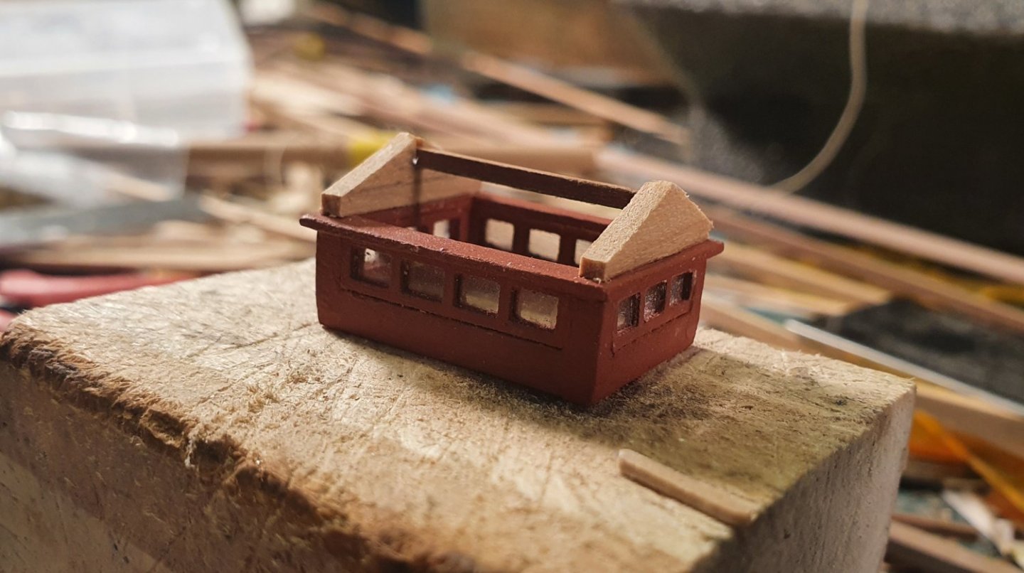
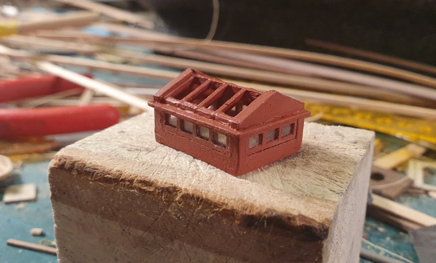
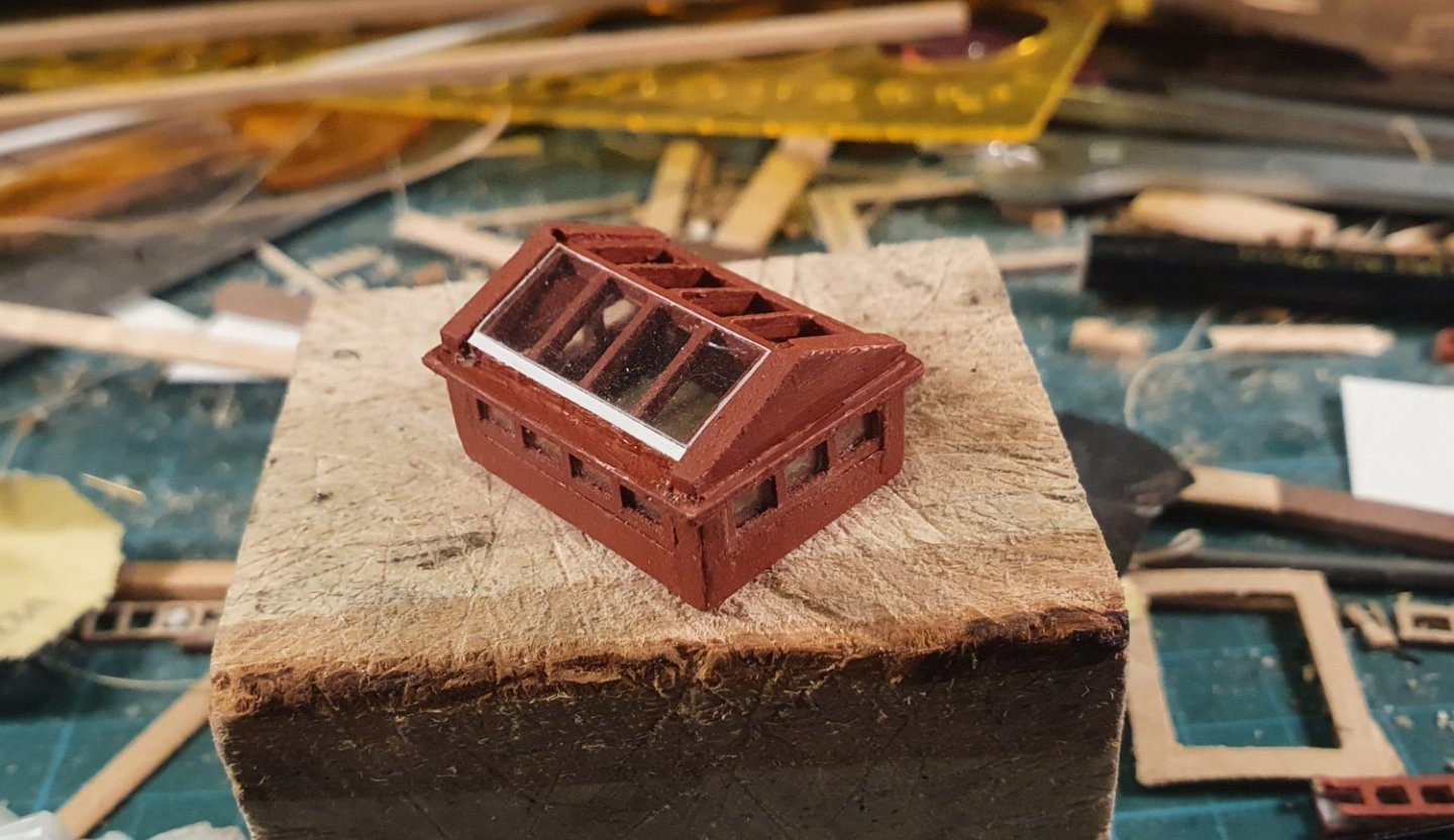
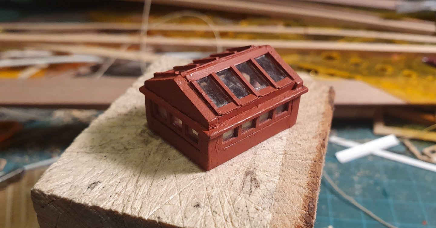
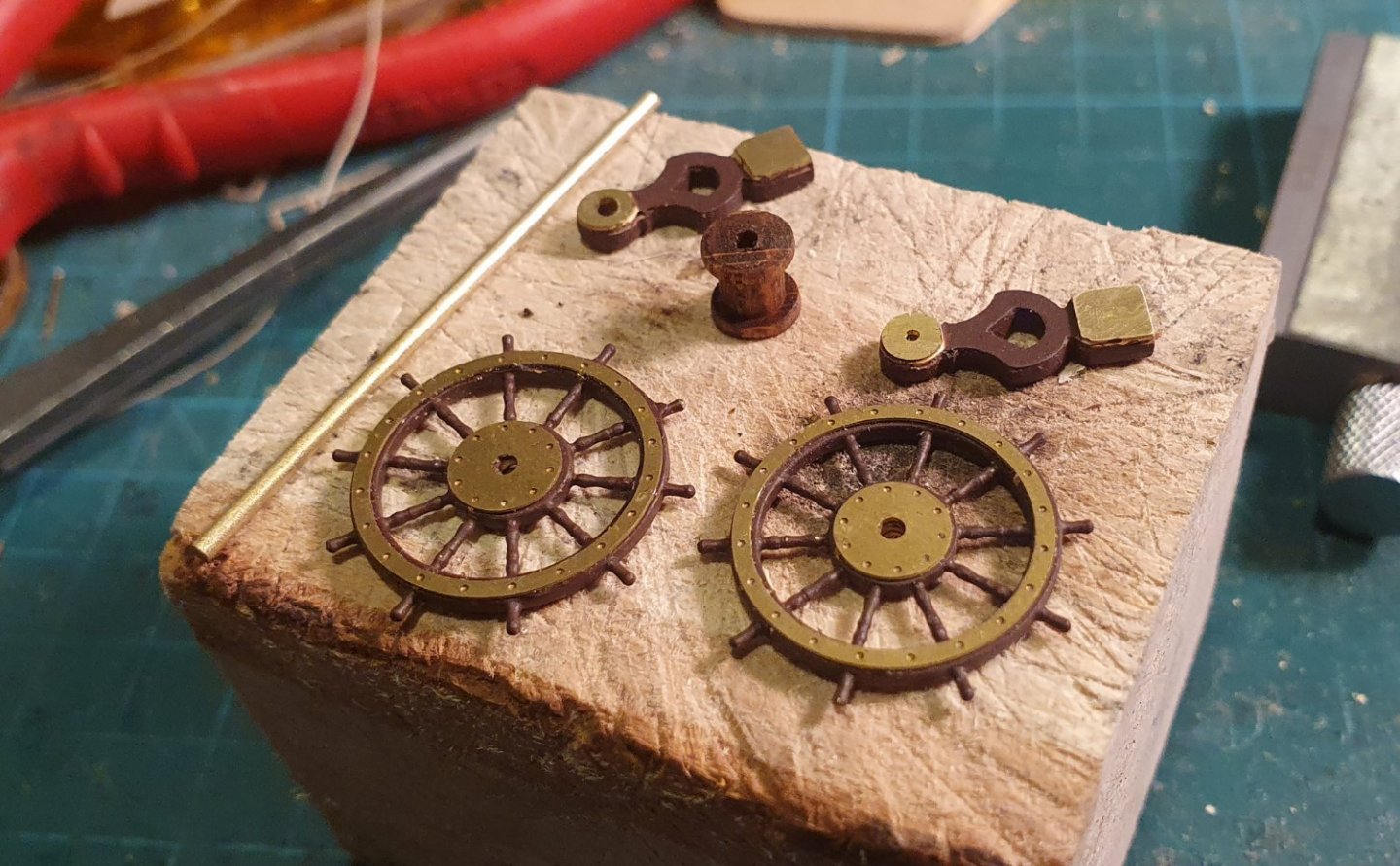
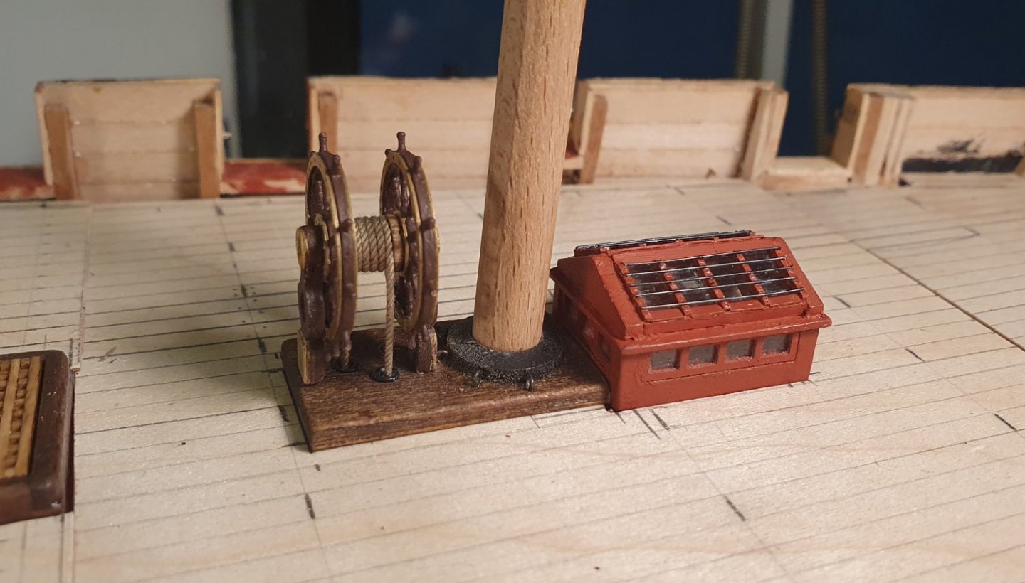
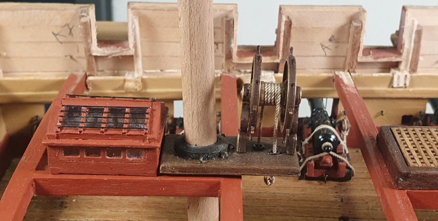
Time to make a start on the planking for the next set of decks. To make my life easier I chopped the false deck into six pieces. I started off on the gangways to warm myself up for the rest of the job. I added a small upstand which runs along the inboard edge of the gangway. This is shown in the AOTSD drawings and it is useful in that it hides the exposed edge of the false deck. The planking was fairly easy with just 4 straight planks and an edge filler piece. I added trenails but, as this is a very visible part of the model, I took the added precaution of measuring their position rather than installing them freehand as I did on the lower deck. I added a trim piece to the top of the quarterdeck breast beam and forecastle breast beam. This will give the deck planking something to butt up against. The junction between the gangway and forecastle has some complexity but close enough to the drawings. I then located the next piece of deck which is part of the quarterdeck. I checked that the gratings, ladderway and capstan step all matched up with what was happening below. I thought I might change out the companion as the kit version was quite plain. I didn't have much to go on by way of drawings and it seems that there was quite a variation in the design of these structures. The AOTSD drawings indicate that it was glazed on the top and sides so I had a place to start. I formed the coamings out of maple and added the lower windows using 3D printed parts and acetate. I initially started off with five windows on the long side to make them square as possible but I soon reverted to the four shown in the AOTSD Drawings. The cornice was made out of maple as well as the gable ends. The ridge beam was fashioned out of a walnut strip. The rafters and beam fill were 3D printed. Windows were made out of acetate while I used styrene for the rest of the mullion covers and flashing. I added some protective bars which were 0.5mm diameter brass rod. These bars look a tad heavy so I swapped them out for 0.3mm diameter steel wire. Once finished I was unsure if it was any improvement on the original. The original consisted of 8 pieces while this one has 74 so it was a whole lot of bother for no real gain. I think that I would have to reduce the structure by about 25% to give it the lightness I was looking for. It looks better from the inside though. The ship's wheel that came with the kit was a bit thin. I decided to upgrade to the Caldercraft luxury version. This is a little thick but has a lot more detail than the original. It was quite easy to put together. I used the kit stanchions and lathed the drum out of a beech dowel. I formed the spindle out of 1.5mm brass rod. I added some dark walnut paint and left exposed brass sections to give it a bit of pop. I mocked up the companion, ship's wheel and dummy masts to see how they all went together. I added a step below the ship’s wheel and mast collar. The NMM drawings hint at this being there although it looks like it is flush with the deck while I have made mine sit proud of the deck. The tiller rope is 0.8mm diameter. It looks a bit too chunky to me so I will probably swap it out for some 0.5mm. I am pondering the bitts that sit between the companion and the mast. These are shown in the kit drawings and the contemporary models with a cross piece while the AOTSD and the NMM drawings the cross piece is omitted and there is just a pin. I am leaning towards the cross piece though.


-
It must have been really cramped. 270 crew and only 2 seats of ease. Almost as bad as a budget airline.