HOLIDAY DONATION DRIVE - SUPPORT MSW - DO YOUR PART TO KEEP THIS GREAT FORUM GOING! (Only 13 donations so far - C'mon guys!)
×


DavidEN
-
Posts
136 -
Joined
-
Last visited
Content Type
Profiles
Forums
Gallery
Events
Everything posted by DavidEN
-
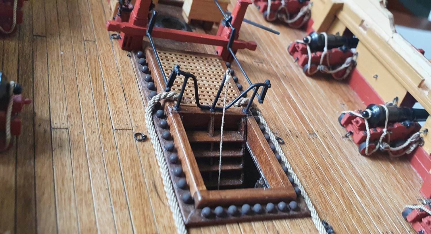
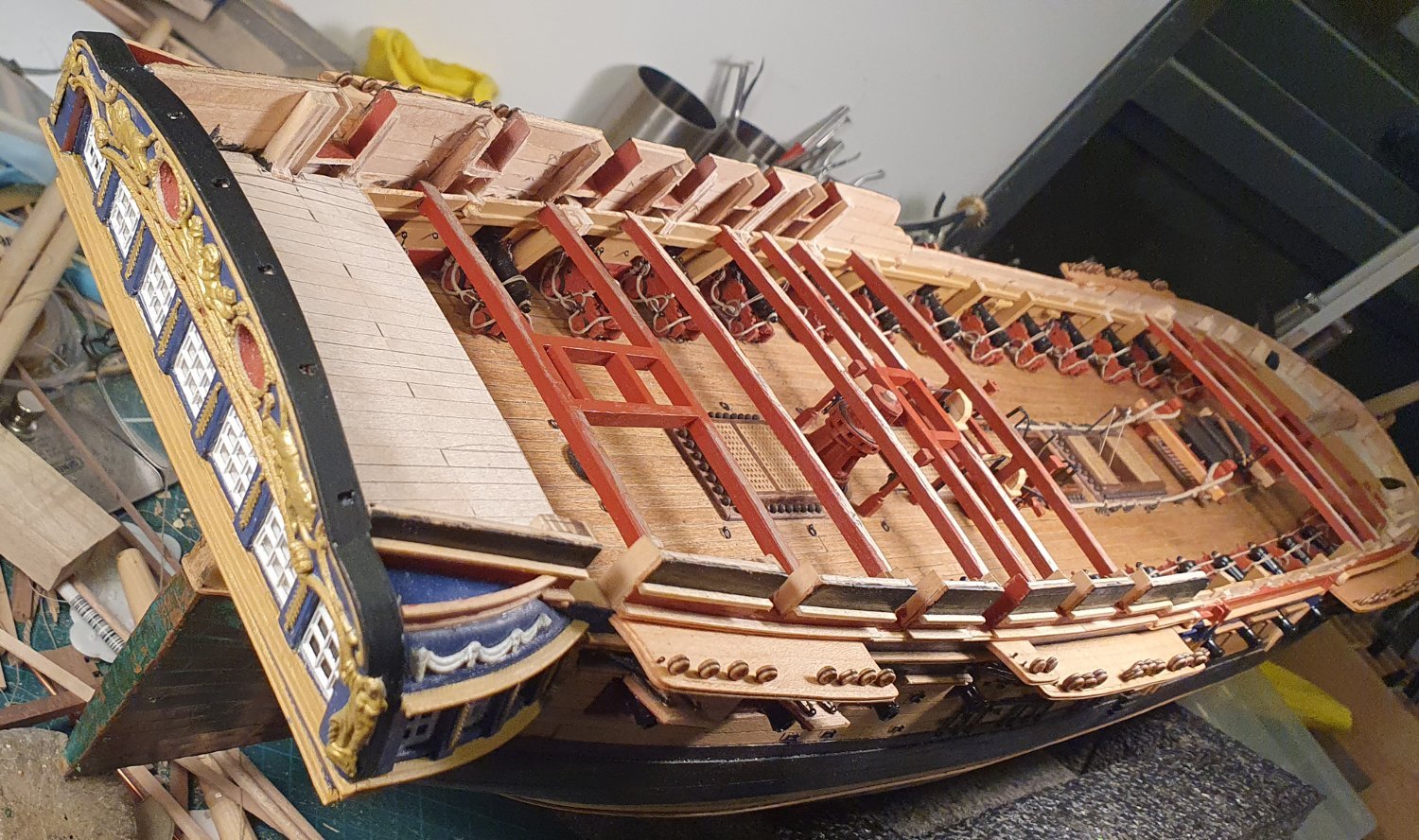
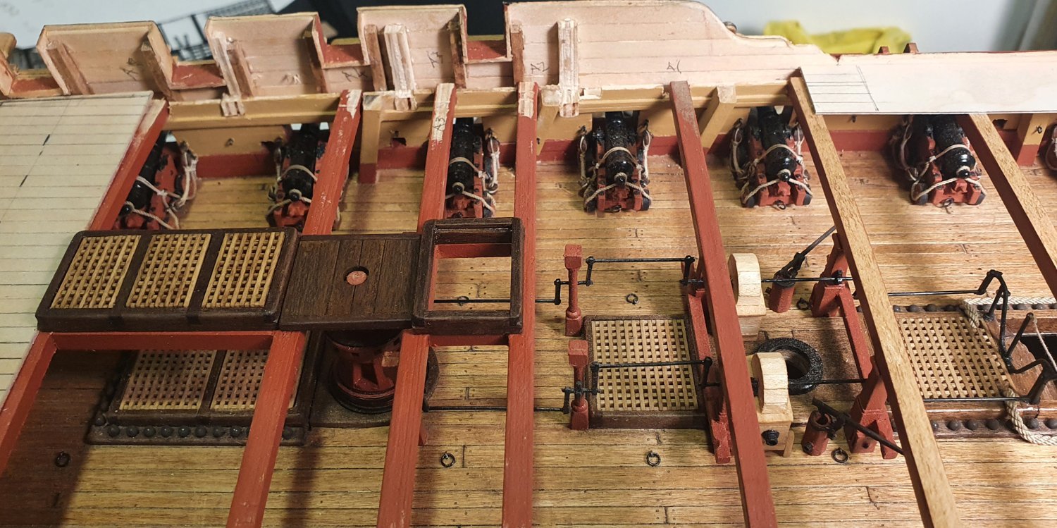
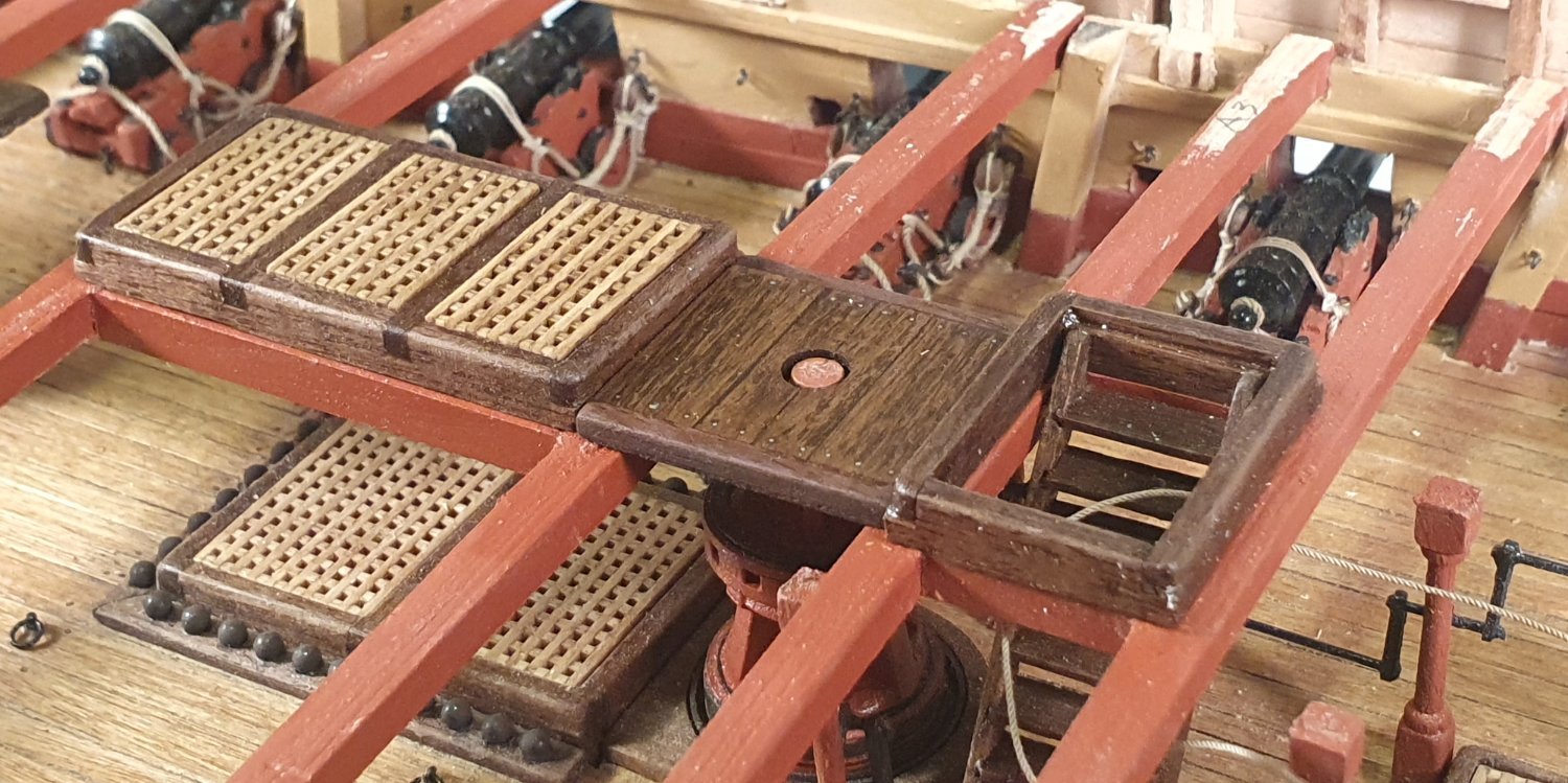
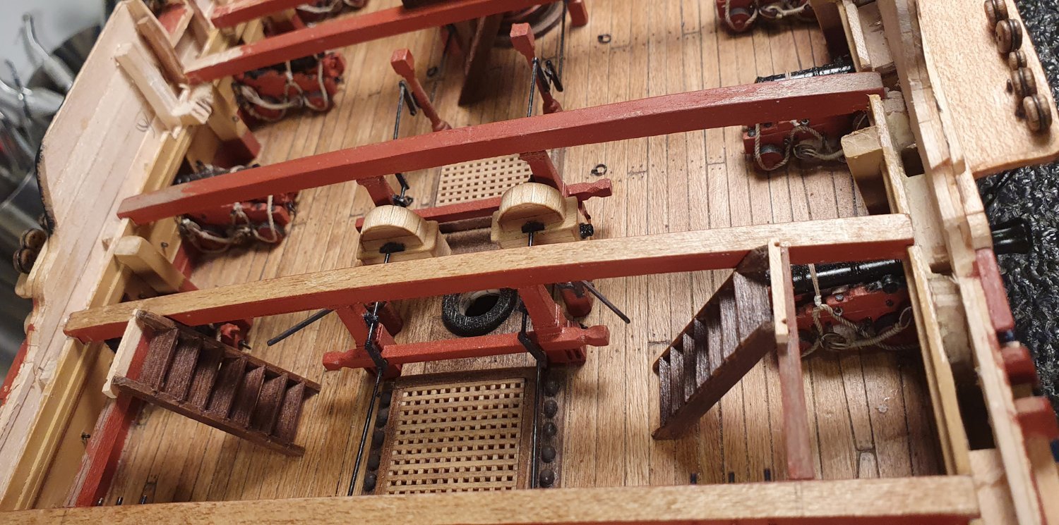
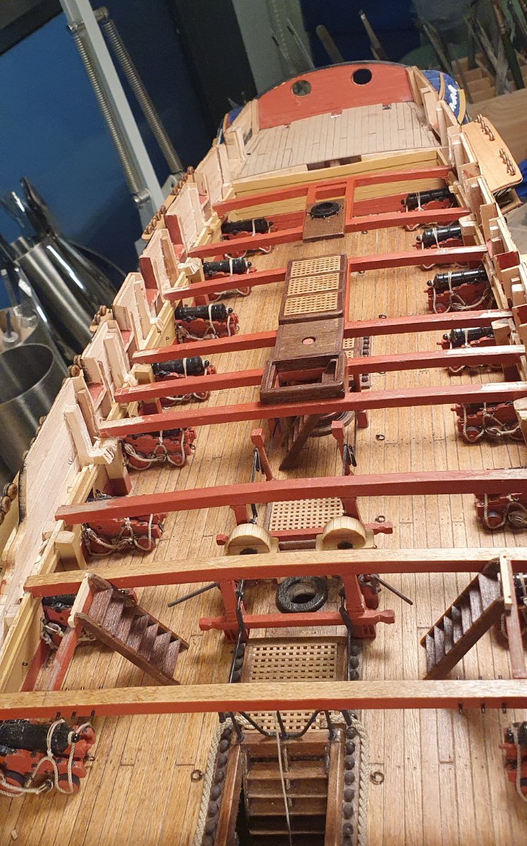
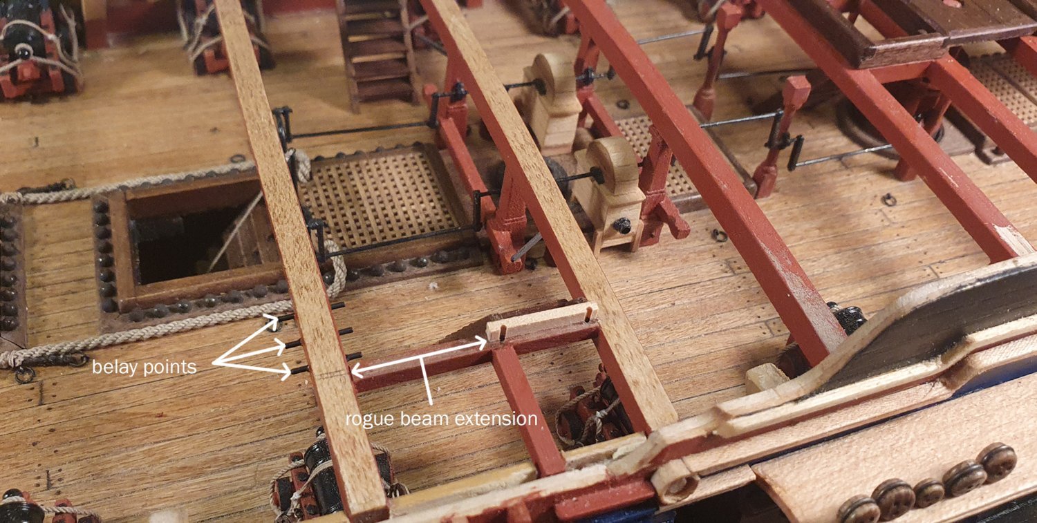
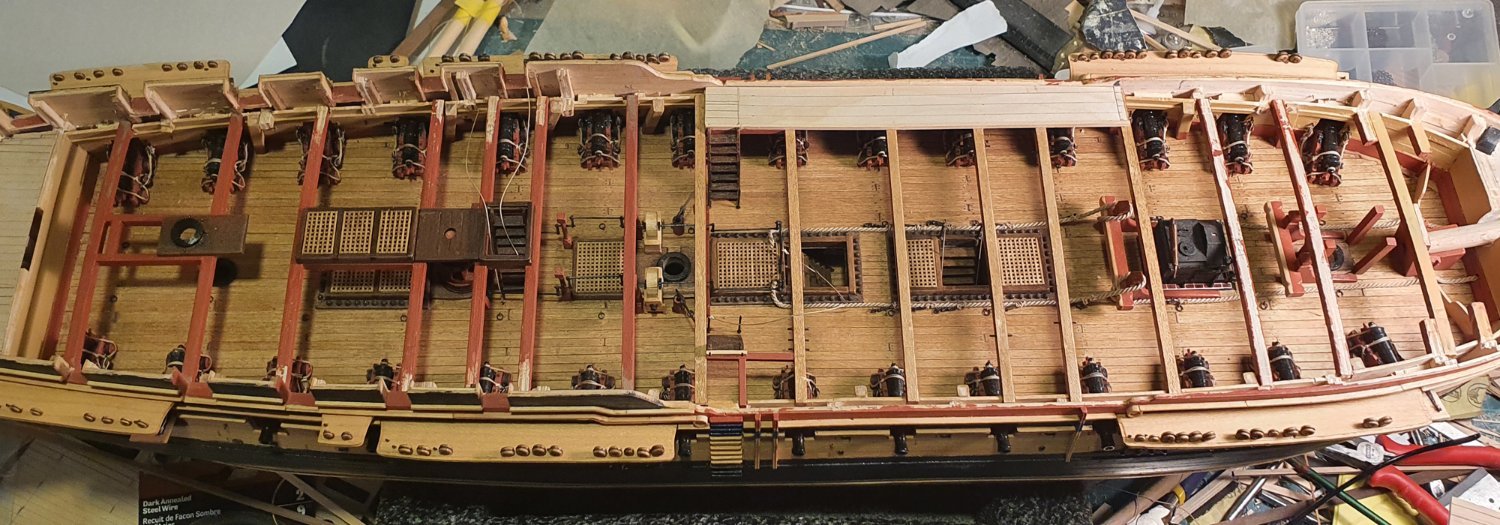
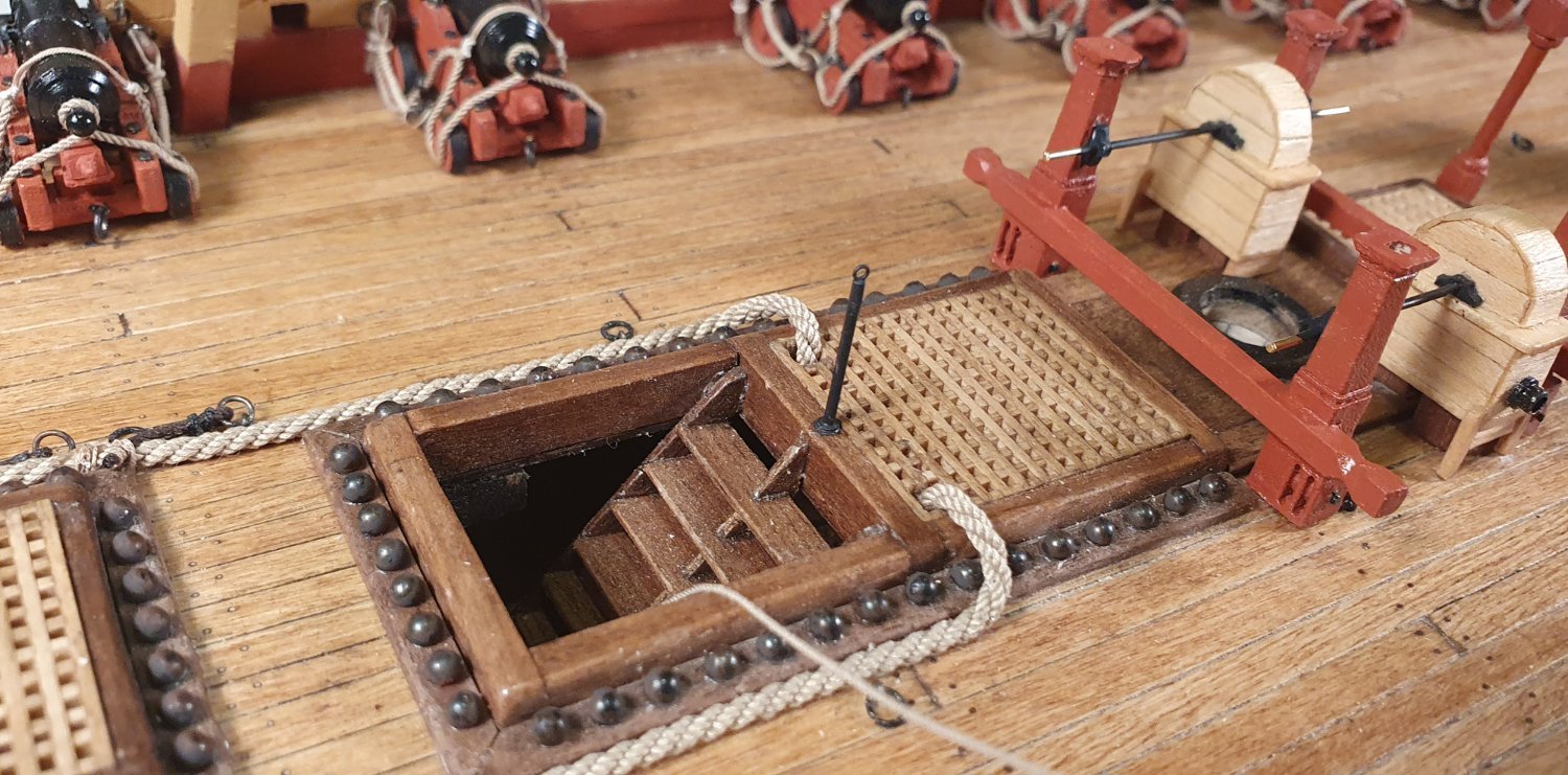
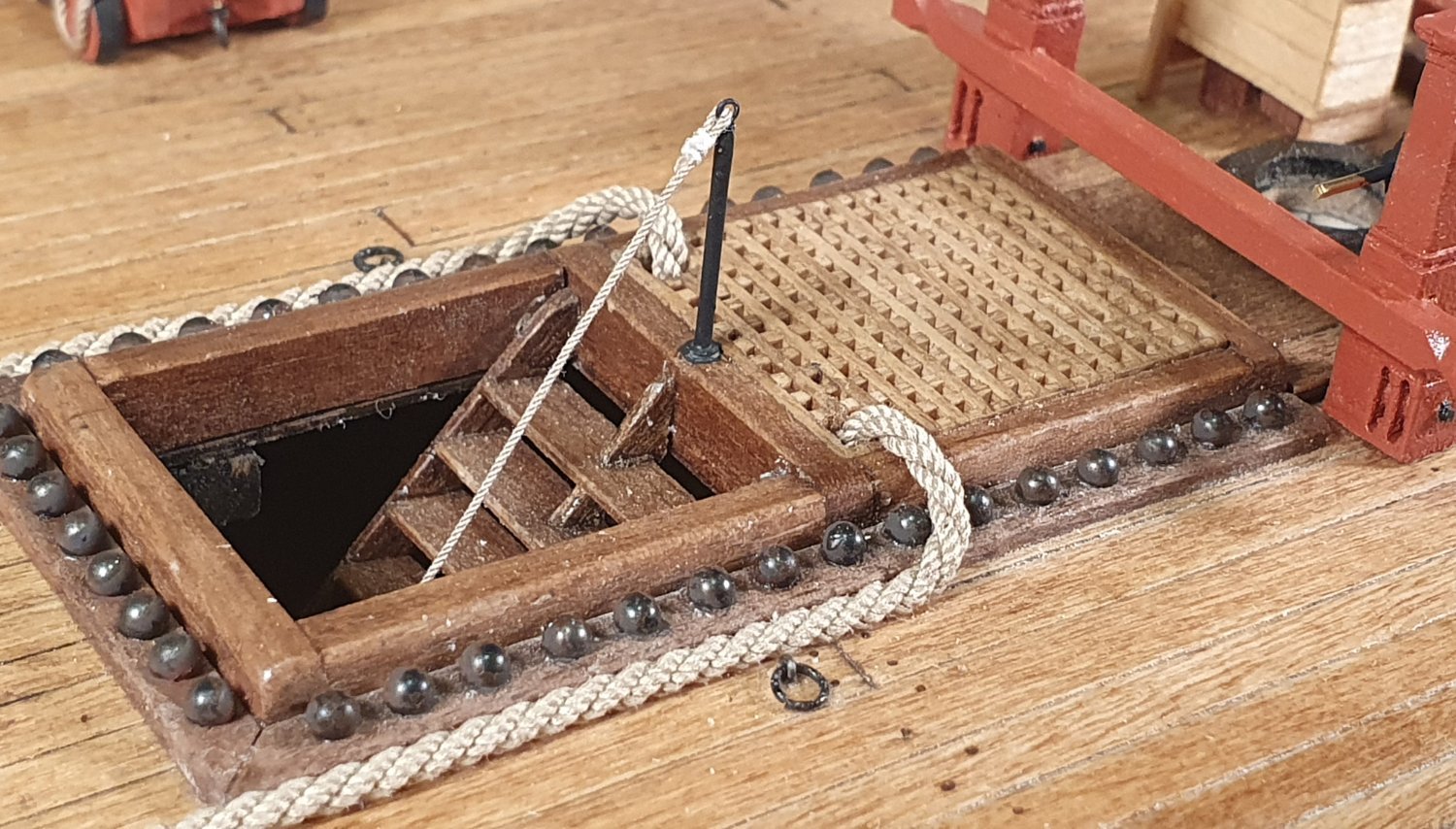
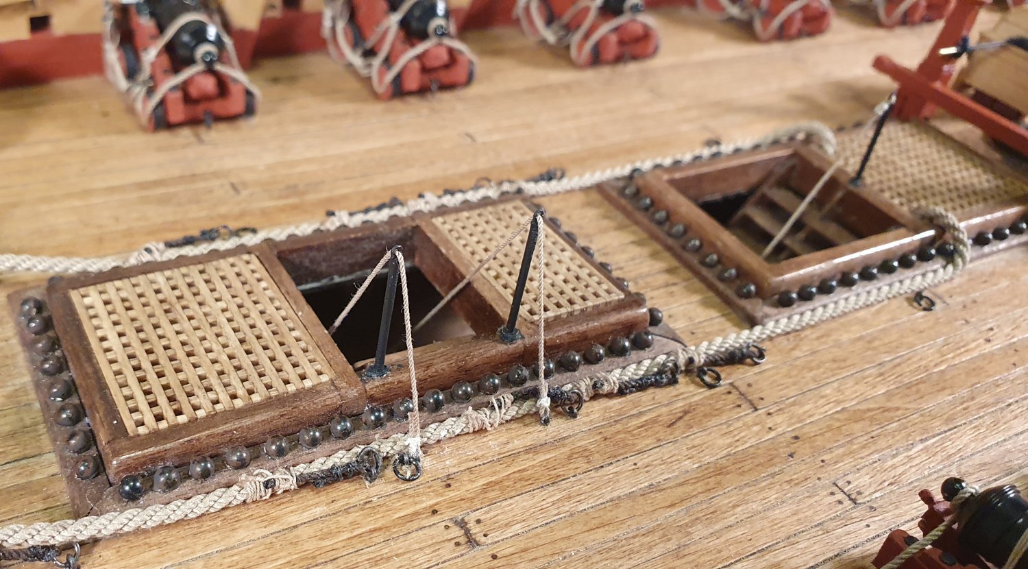
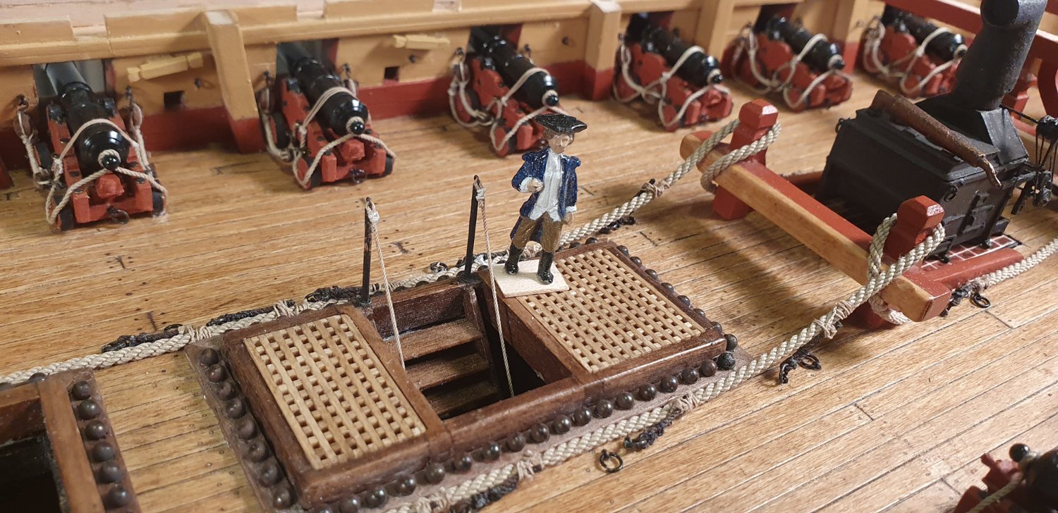
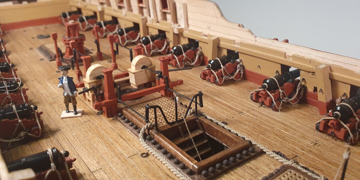
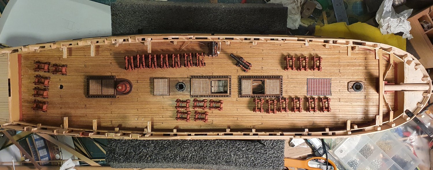
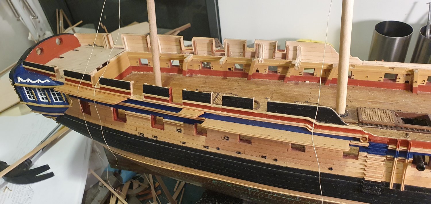
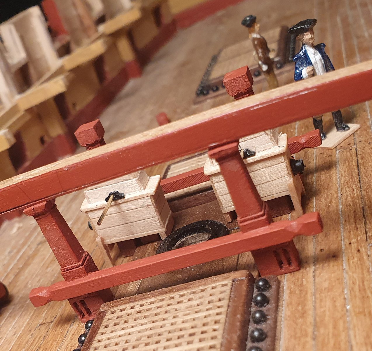
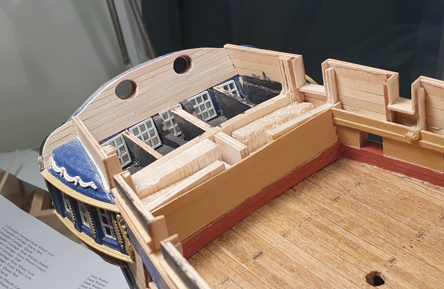
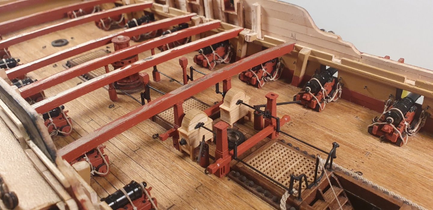
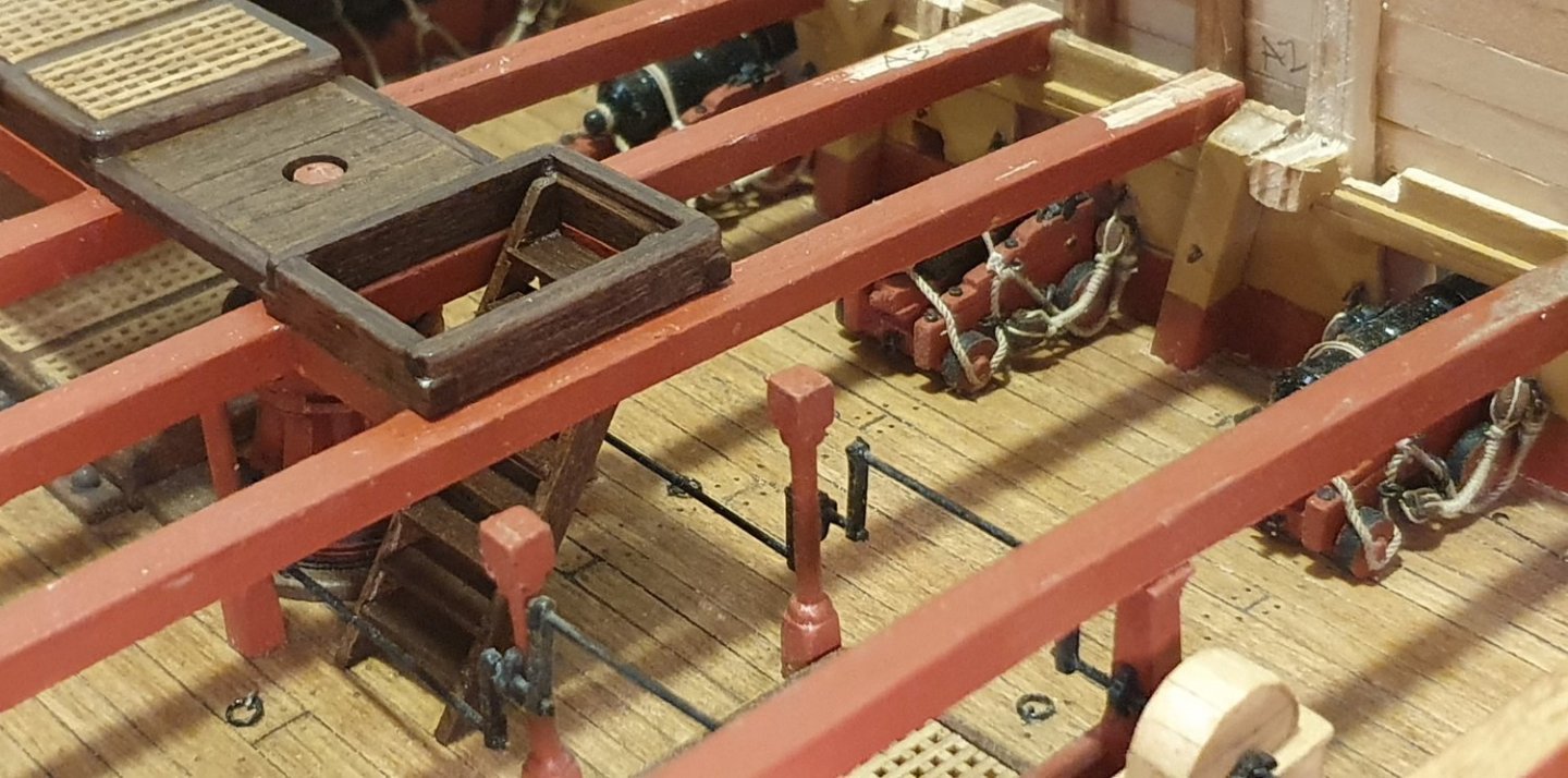
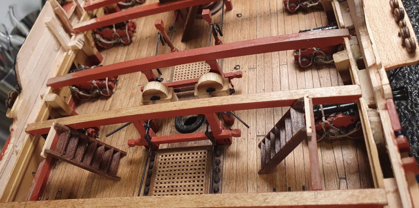
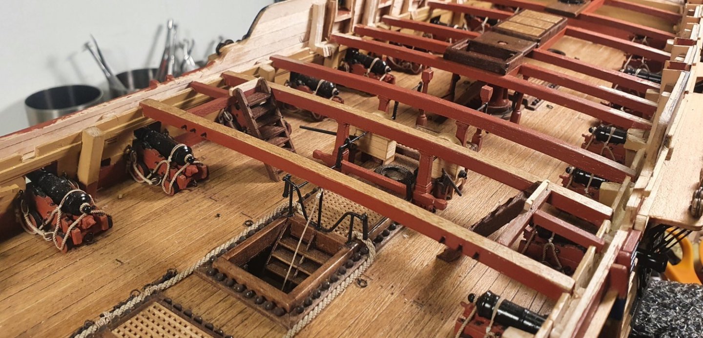
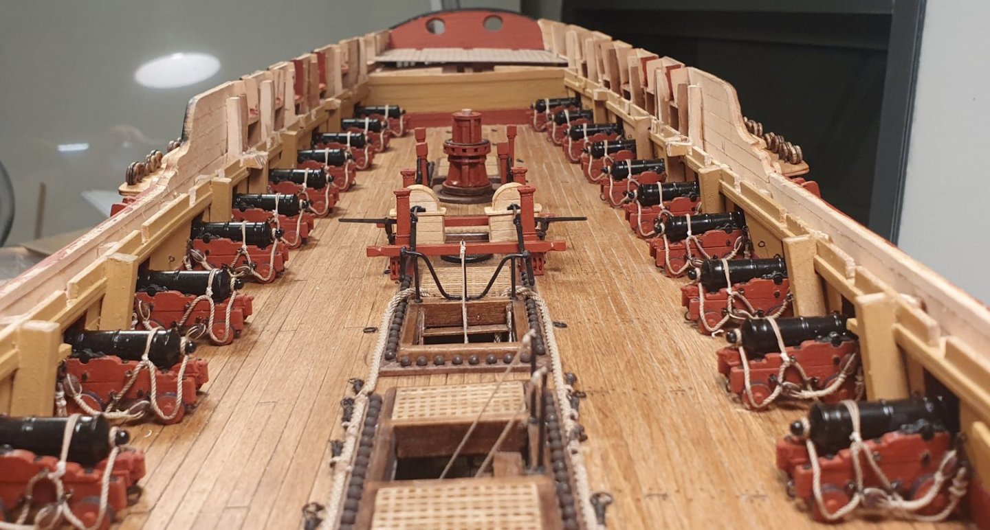
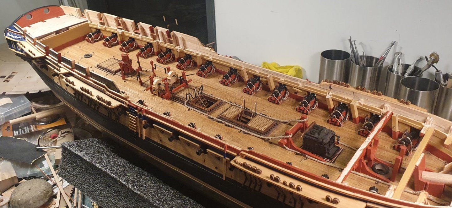
I decided not to attempt the internal partition work for the gun deck as I had moved some of the gunports to avoid the bulkheads which meant that the partitions would need to be relocated and that would have caused a clash with a deck hatchway. Decision having been made it was now time to get on with covering up the gun deck. I first had to install all of the beams that carry the quarterdeck and forecastle as well as the skid beams. I started at the quarterdeck and proceeded as per the kit drawings however when I dry fitted the false deck for this area I noticed that the framing ignored anything that was happening above. Beams sailed through openings, clashed with the capstan position and bypassed columns. I then decided to saw off the bulkhead beam stubs and locate the beams where they made most sense. This ended up with quite large distances between the framing so I had to introduce some additional members to ensure that the deck does not have to span too far and run the risk of producing large deflections. With great hindsight I probably should have just located the beams as per the NMM drawings but this would not confer any great advantage other than me being smug in the knowledge that I had an authentic framing layout. Instead I ended up with a slightly odd looking framing layout. I introduced carlings to take the coamings around the staircase, gratings and companion having learned my lesson from early on in the build. I constructed the coamings around the ladderway as well as the gratings. I decided to not attempt the slight taper to these gratings as shown in the drawings as I was not confident of achieving a satisfactory result. I built the step that sits under the upper capstan out of walnut to match the rest of the fittings in this area. I decided to build and install the ladders at this point while I still had reasonable access to the upper deck. I also took this opportunity to install the handrail stanchions and deck eyebolts to take the rope handrails the ends of which were tied off at this stage while access was still possible. When installing the ladders that sit forward of the quarterdeck breast beam I modified the structure from that shown in the AOTSD drawings. I introduced a beam that spans between the quarterdeck breast beam and the skid beam. In the AOTSD drawings this should return at right angles and cantilever from the hull but my solution gave me less of a headache. When installing the ladders to the gangway I noticed that they clashed with the handles of the elm tree pumps so I had to yank these out and shorten the handles. I added belaying pins on the after skid beams and forward skid beams as shown in the AOTSD drawings. I noted that most people do not install these which probably means that they are not required for the standard rigging but I have not yet studied the rigging diagrams. They are fairly unobtrusive so if I end up not using them it is not a disaster. The installation of the beams under the forecastle were less problematic with just a slight relocation necessitated by a clash with the stove rotisserie and deck openings. With all of the beams in place I will have to start the deck installation. I will attempt the gangways first as they appear to be quite simple.


-
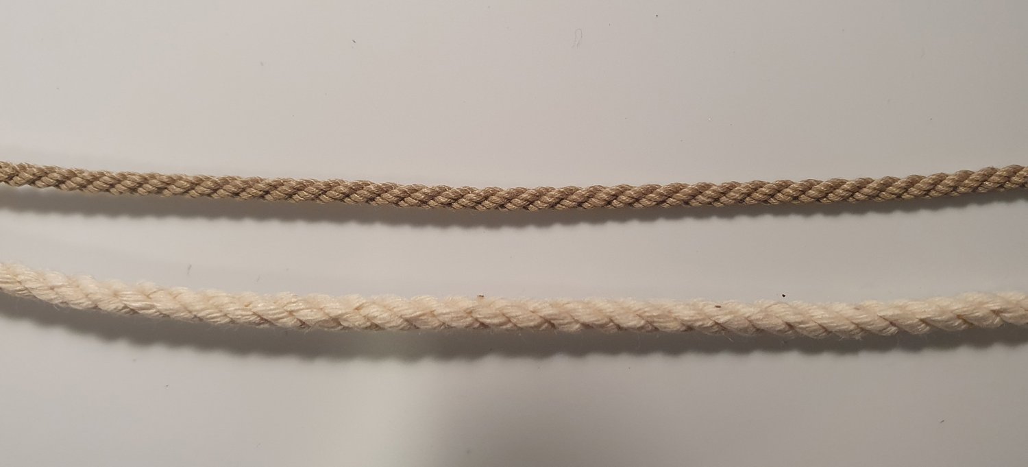
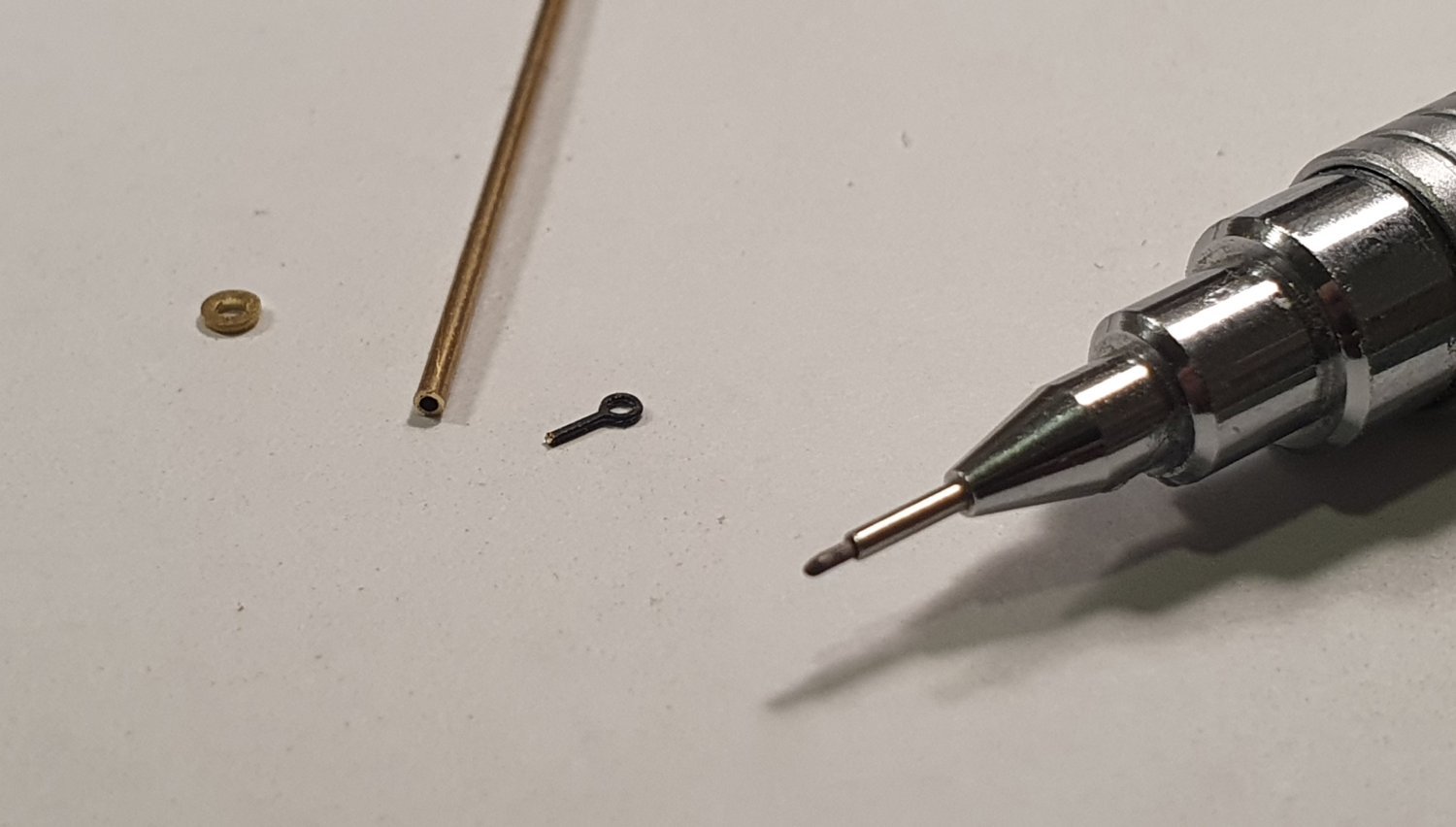
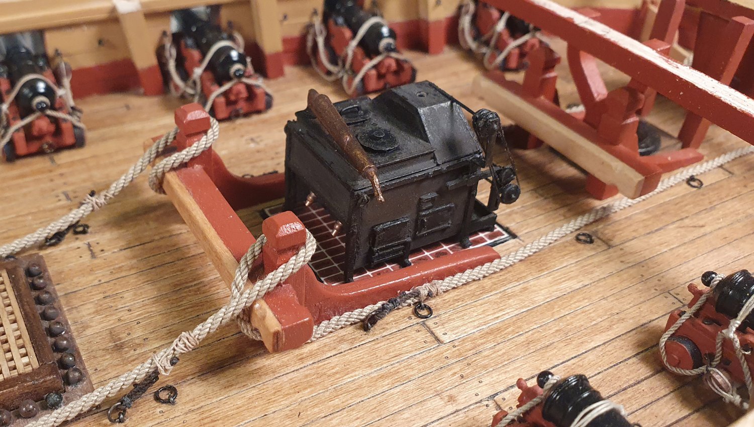
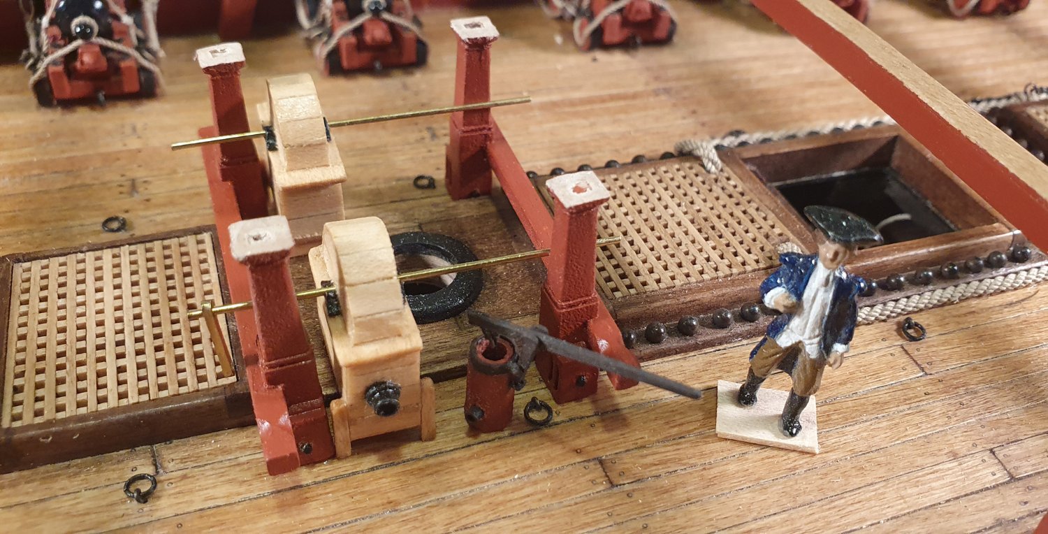
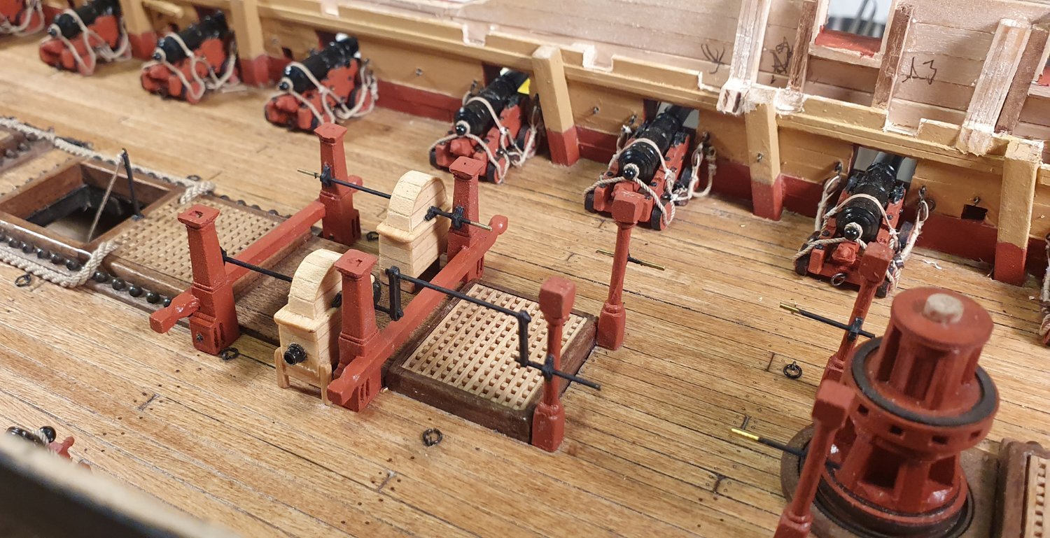
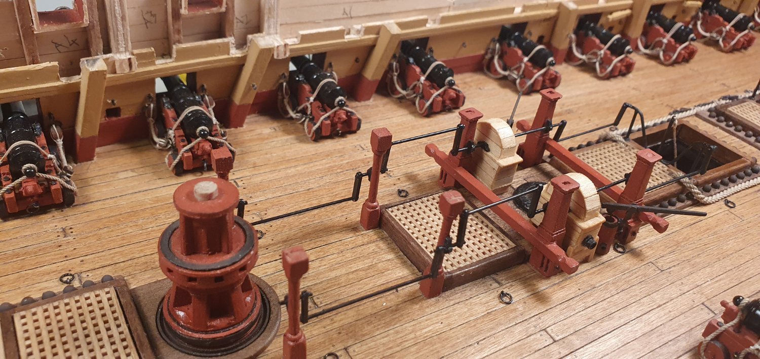
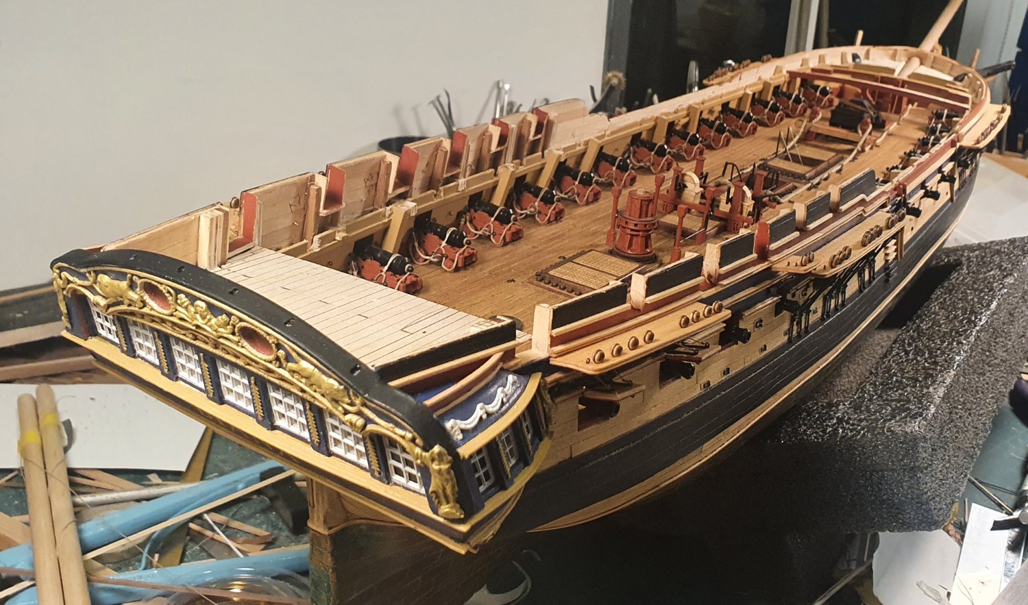
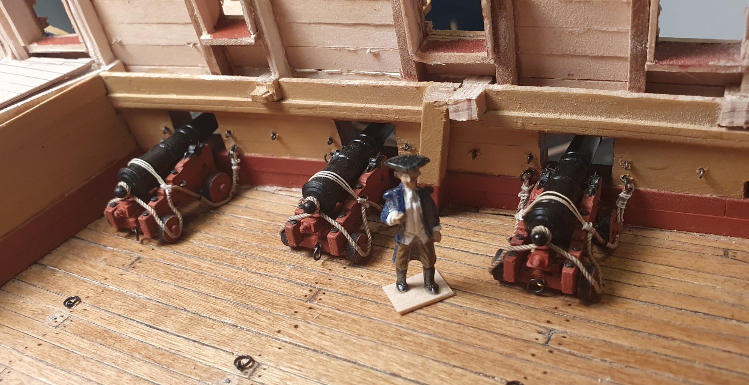
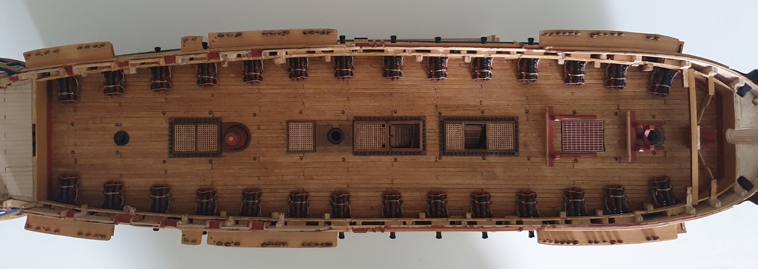
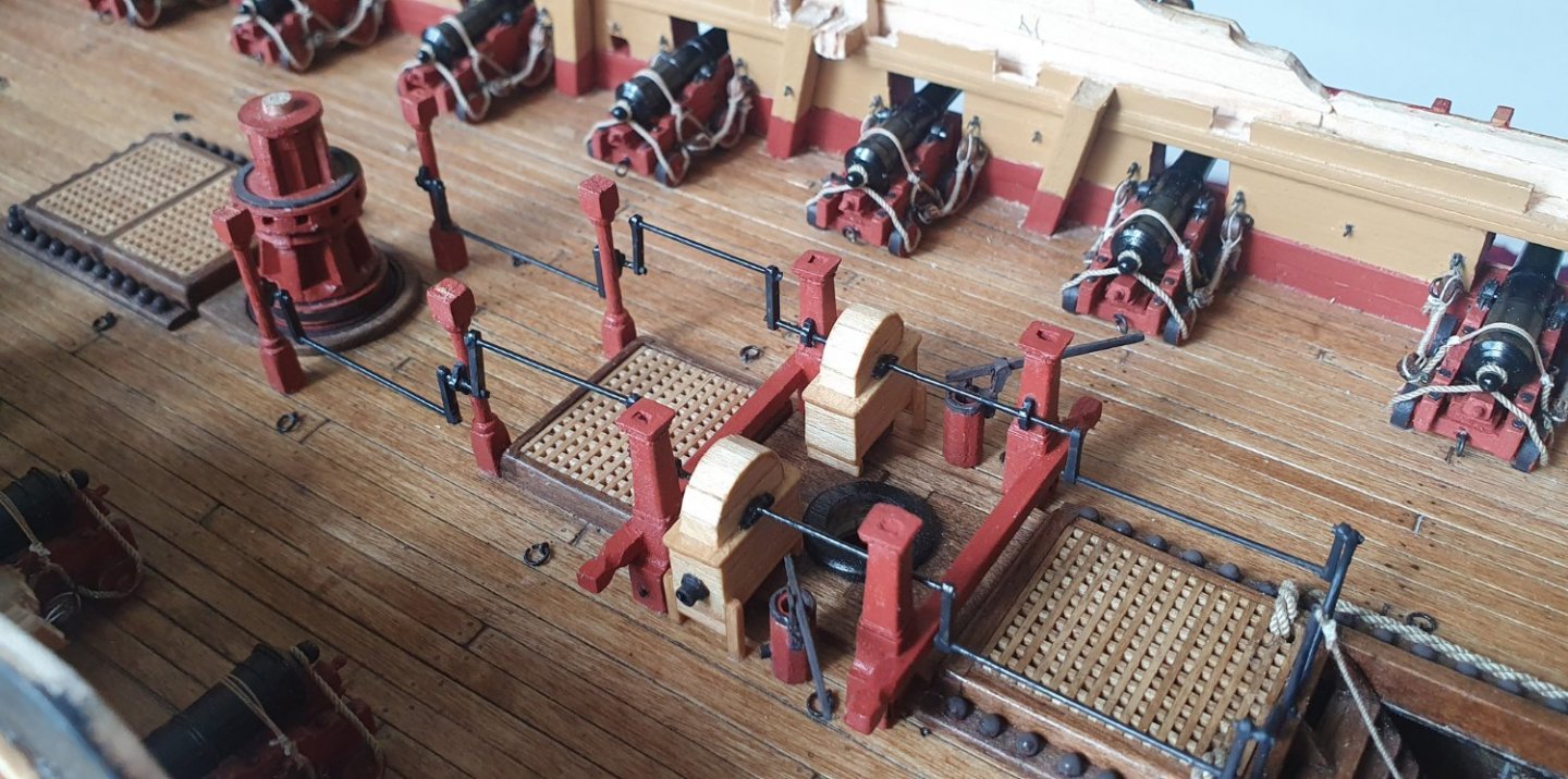
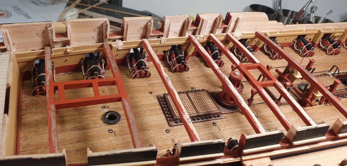
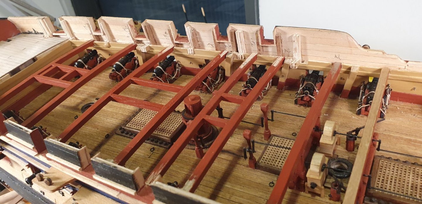
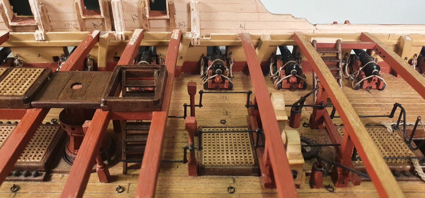
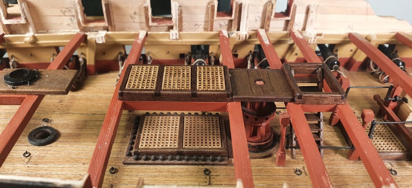
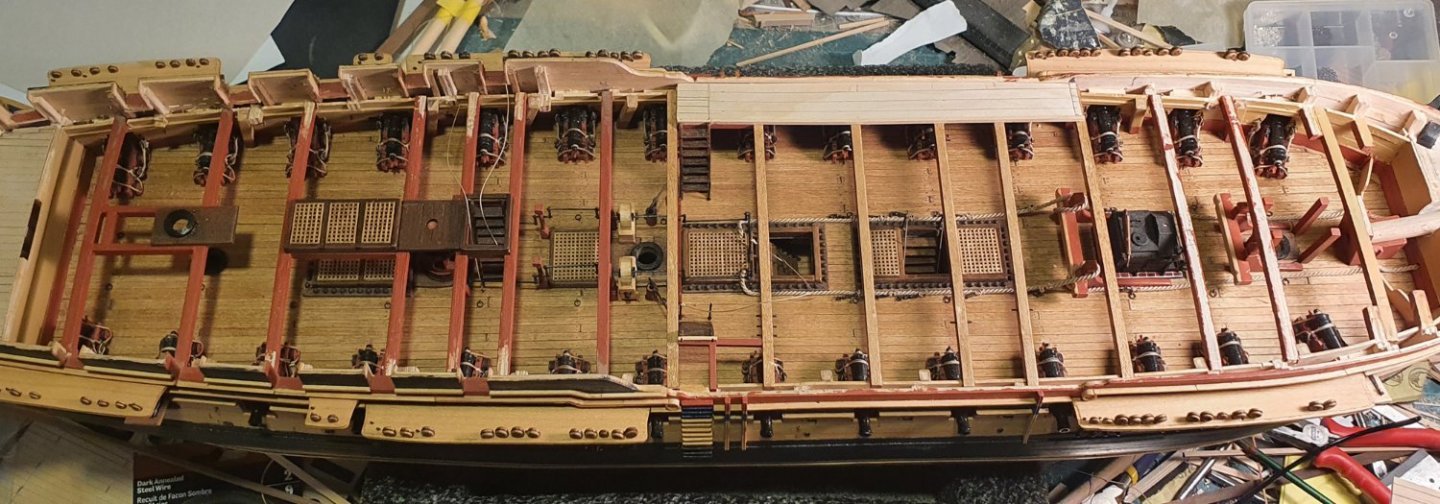
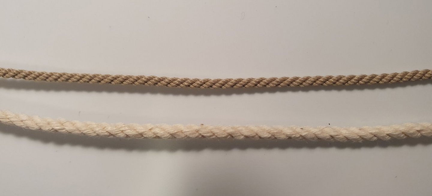
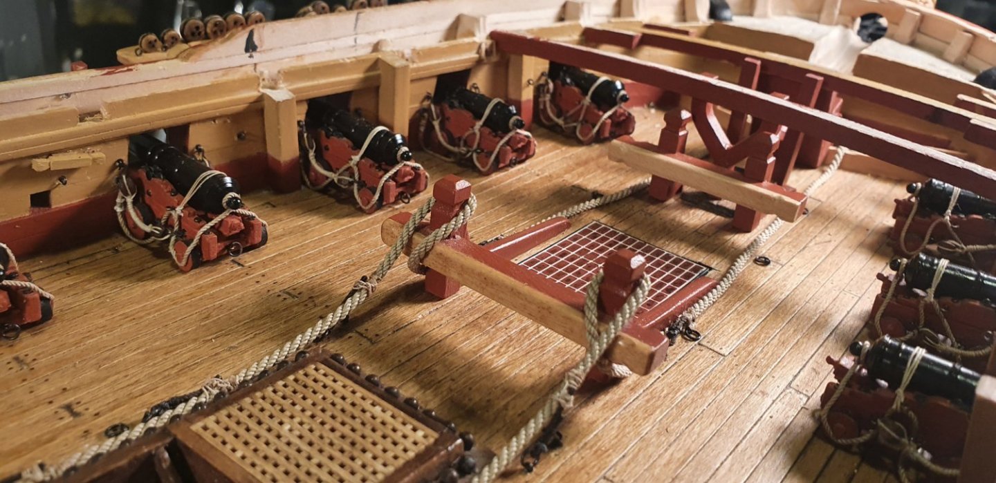
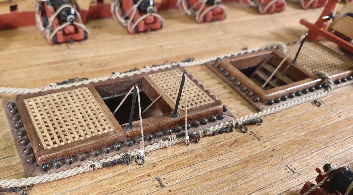
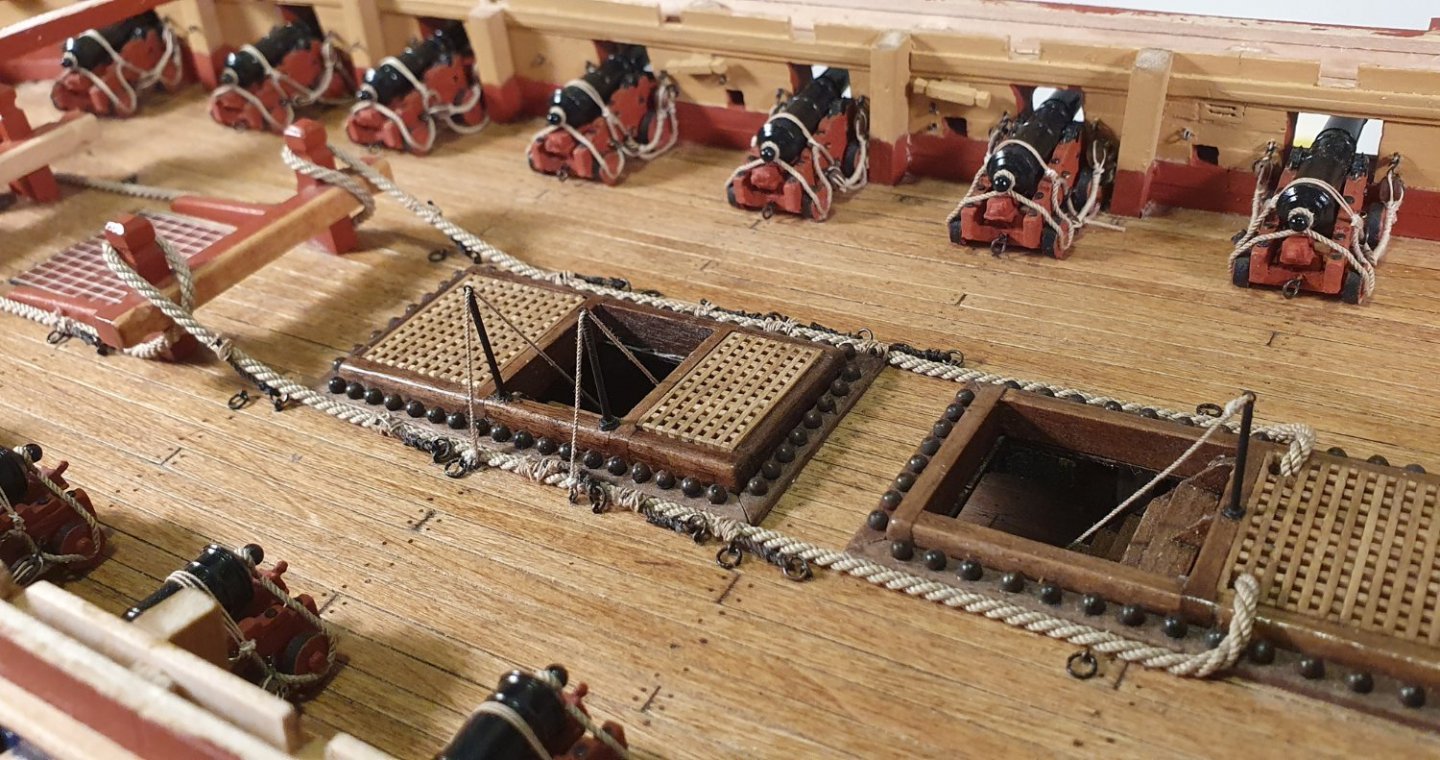
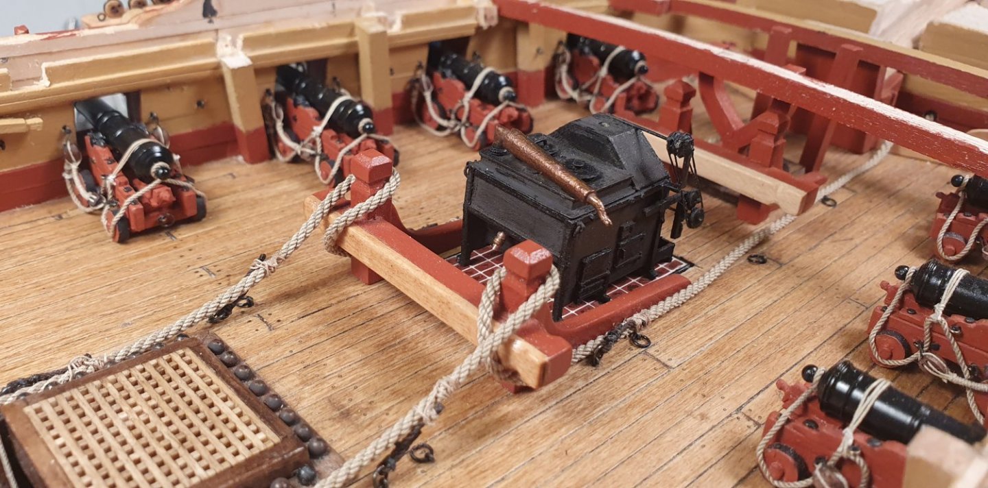
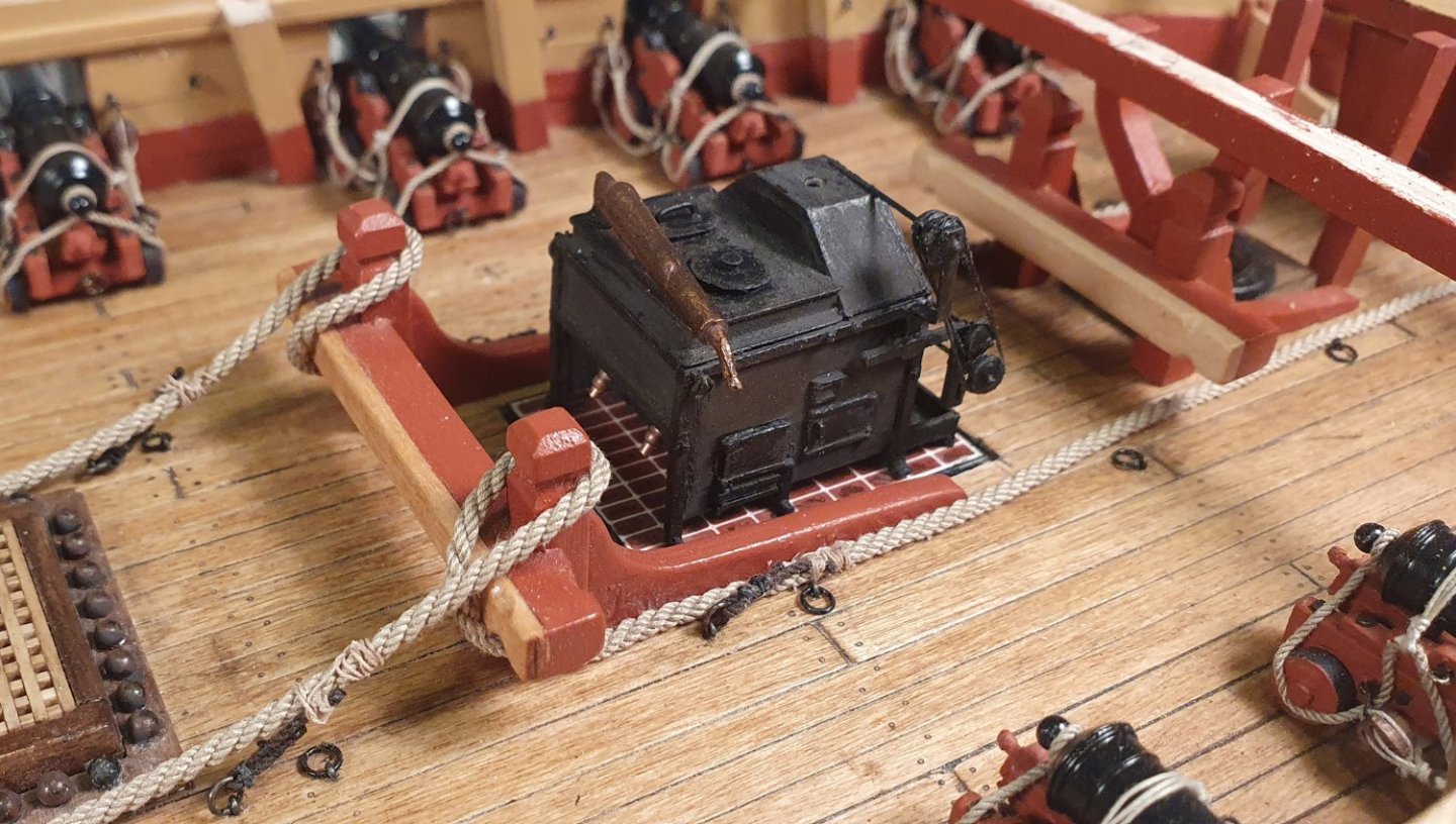
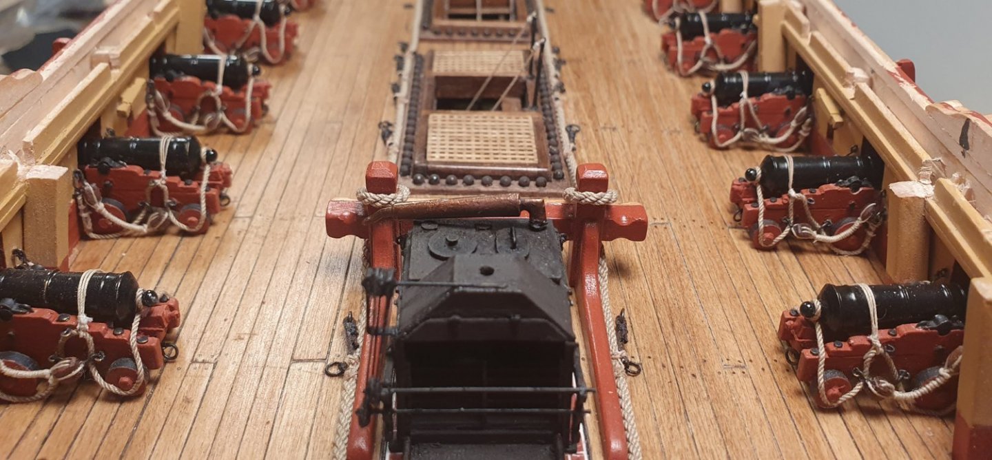
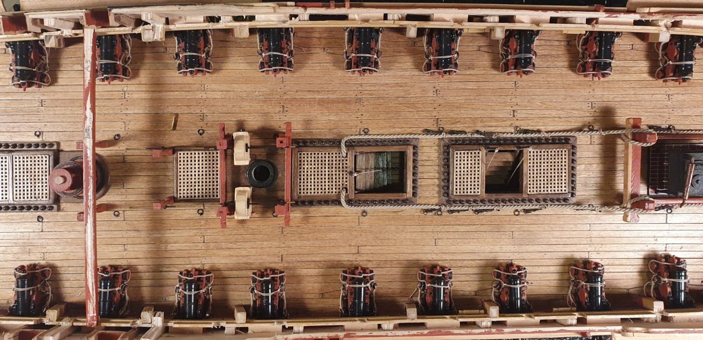
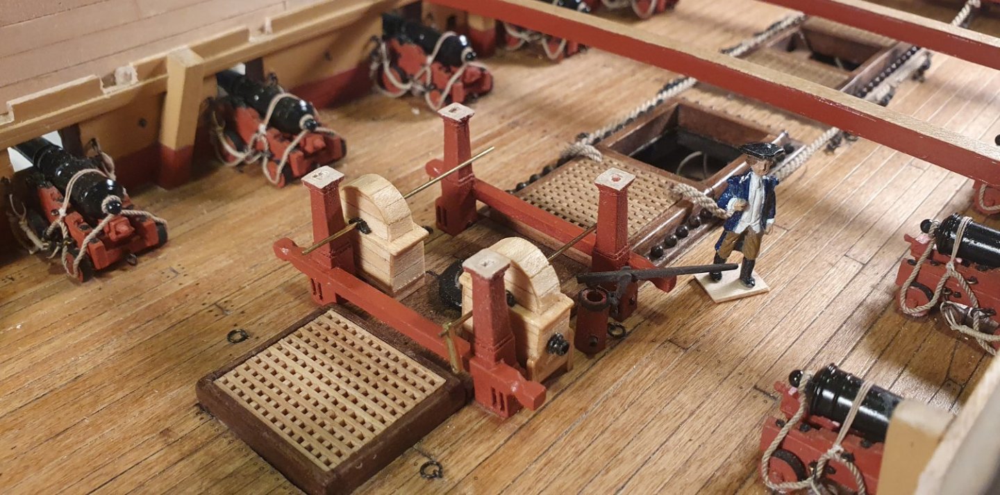
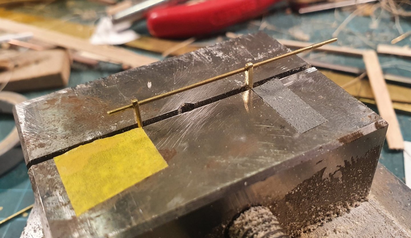
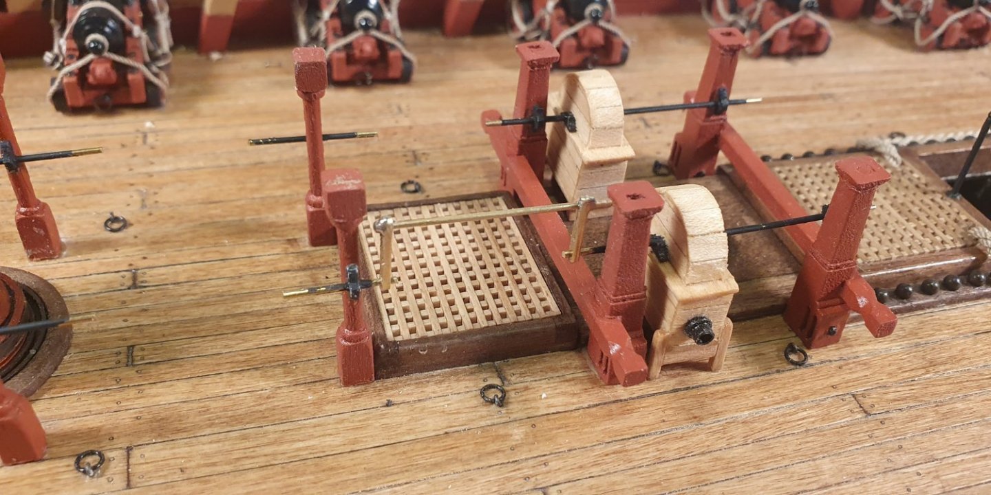
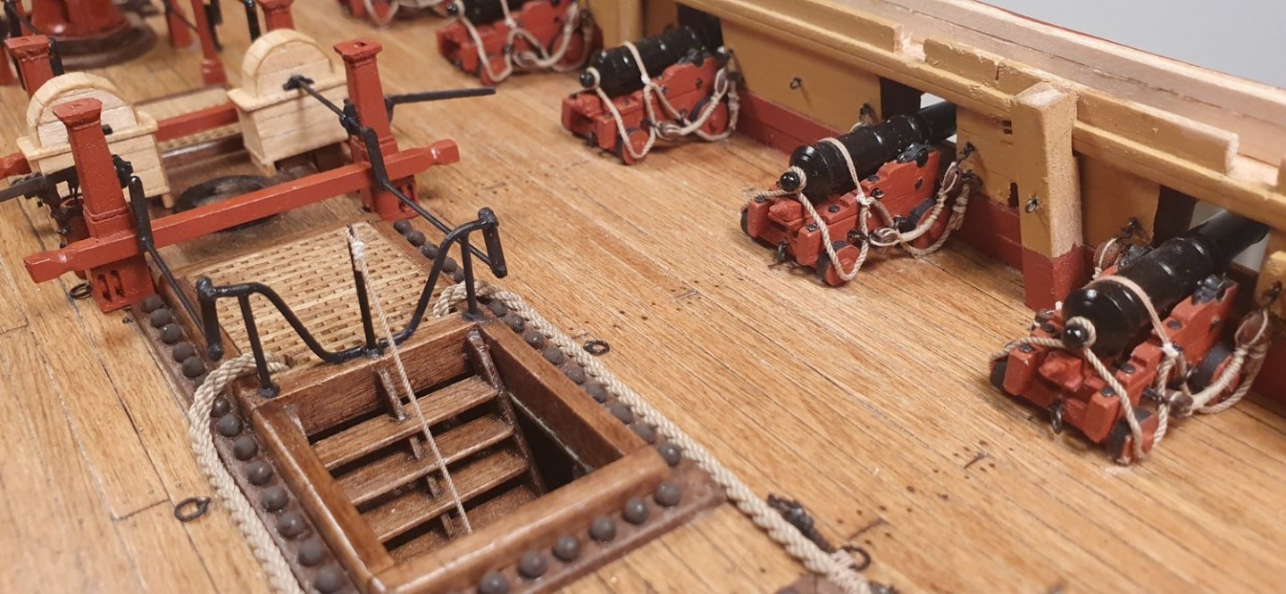
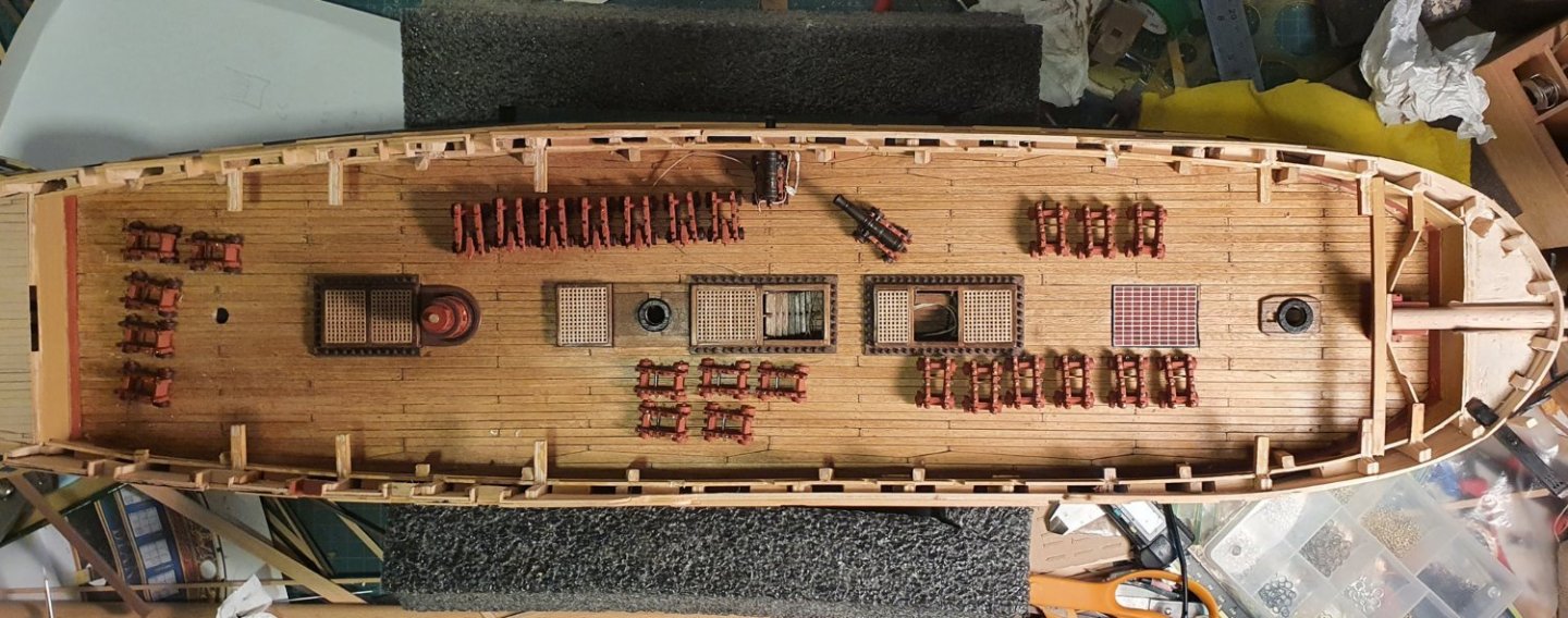
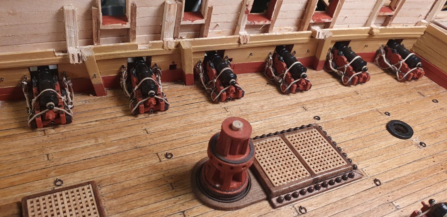
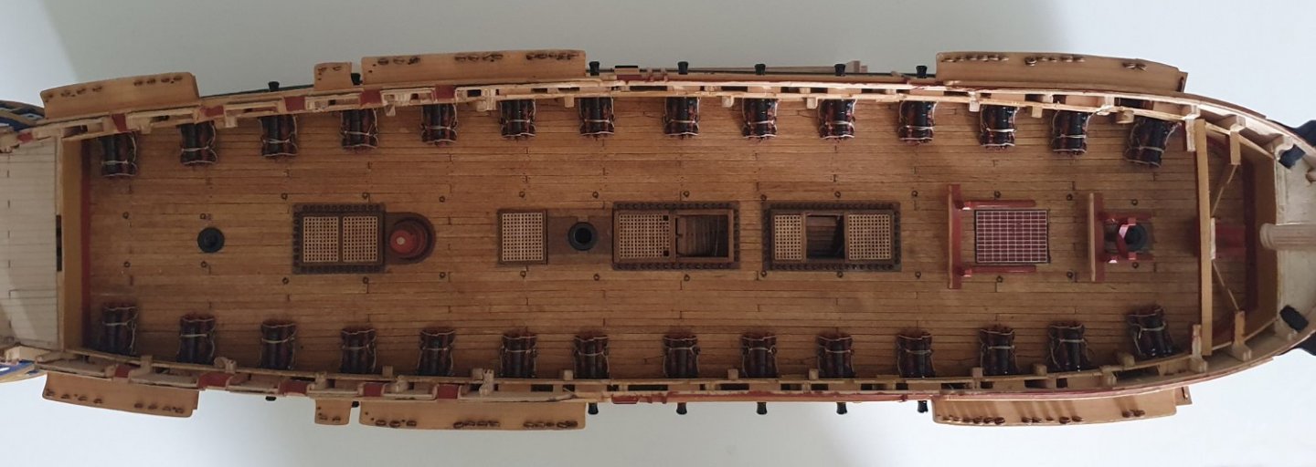
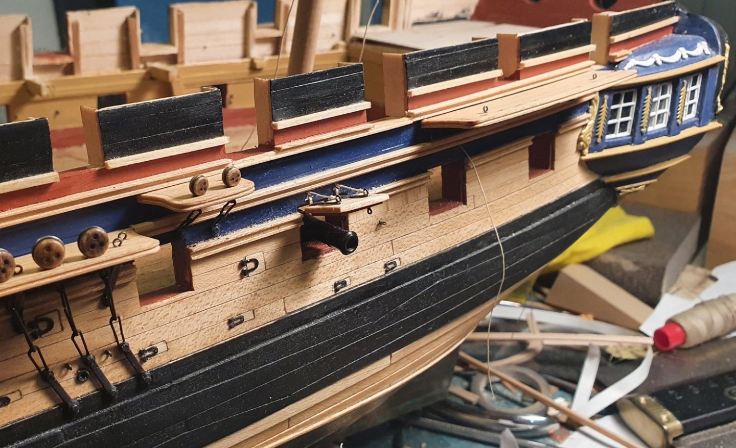
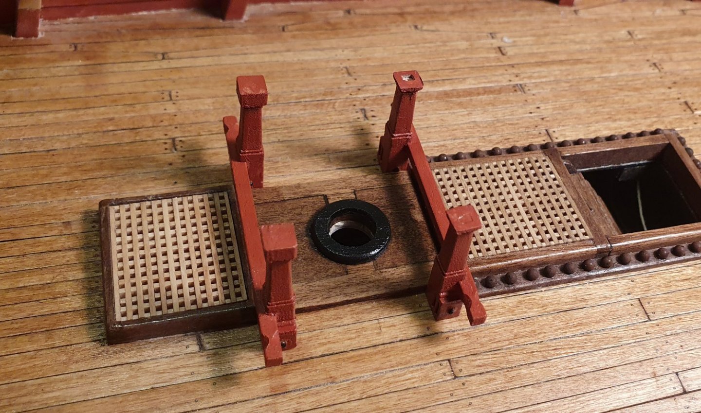
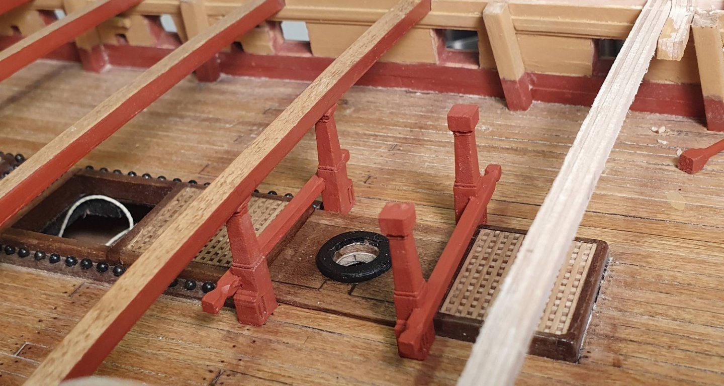
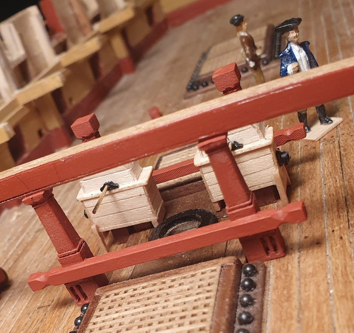
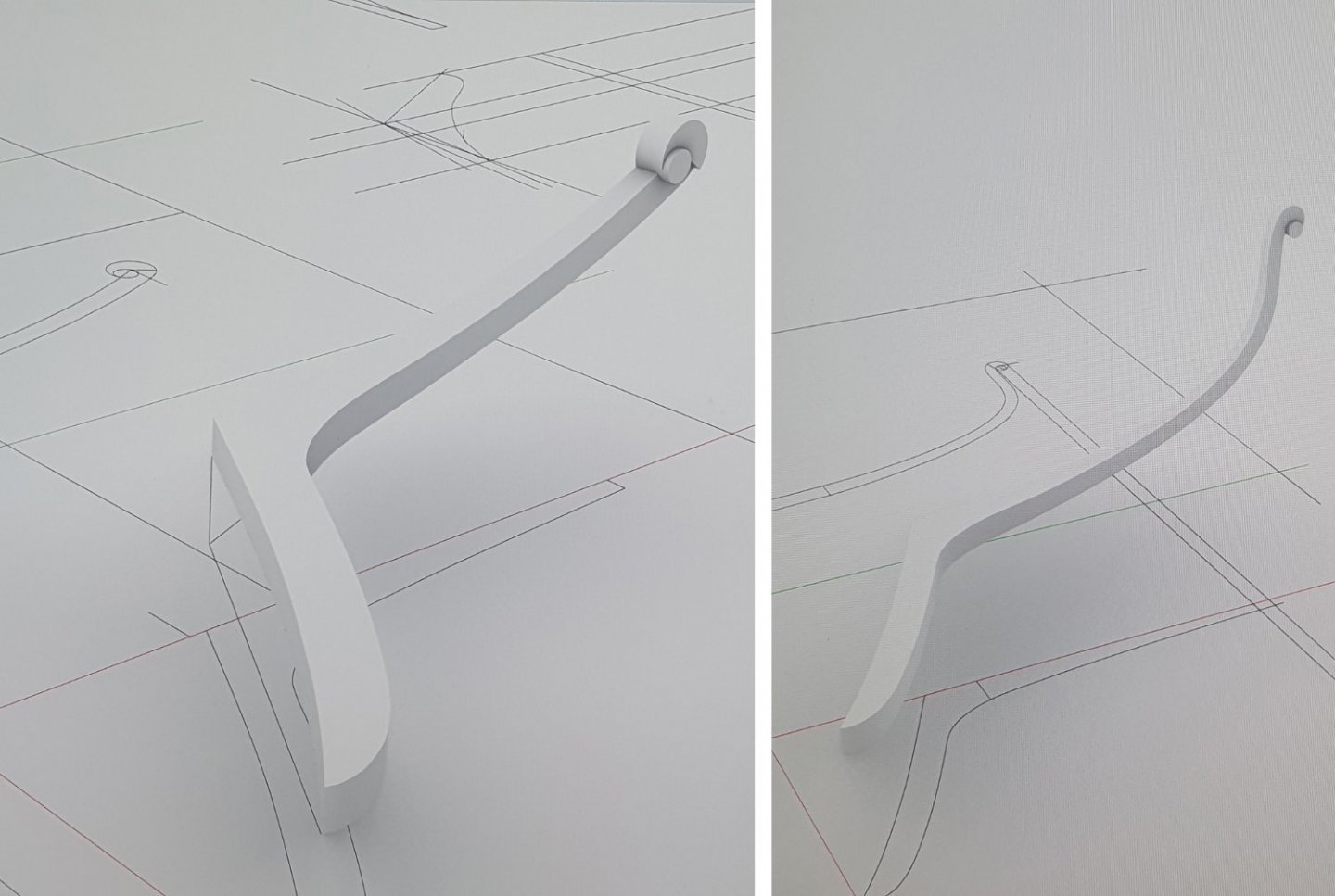
The guns on the main gun deck are now installed. Looking from the outside they seem to line up OK. Time to finish up the gun deck by fixing all the remaining fittings. Most of these have been built already so it is a fairly easy task to locate and install however there are a few tricky bits that will require some effort. I positioned the anchor cable. I could have easily left this off but I quite like the look of a hefty rope sitting on the deck. I wasn't keen on the supplied cable which is labelled as 2.5mm diameter but measures 2.85mm. This is too large and the colour is not the best. I sourced some 2.1mm cable from Ropes of Scale. This is slightly undersized as I believe that a ship of this size would have an anchor cable that would scale to 2.34 mm diameter. The cable itself is much improved from the kit supplied item and it looks very similar to cable I have seen in historic photographs but from certain angles the look was a bit jarring. Perhaps it is a bit too articulated in combination with the sheen and colour I chose but it put me in mind of something my Granny might have knitted. I saw on their website that Ropes of Scale has just introduced a new range of cable-laid polyester rope which seem to have a more muted look. They have also introduced a 2.4mm size which is very close to my requirement. I have speculatively ordered some in a different colour and I am currently awaiting delivery. I hope I will not be too disappointed however I will wait to see how it looks before I decide if I will replace the original as it will be quite an onerous task with all of the upper deck beams now in place. I installed the deck stoppers, six per side. These were fashioned out of 0.5mm rope with ringbolts to attach to the deck. They came out a bit scruffier looking than I intended. I constructed a number of tiny stanchions so I could fasten the ends of the rope handrails. These were made out of a section of 1.0 mm diameter thin walled brass tube with an eyebolt epoxied into the one end. I used a 2mm outside diameter photoetch eyebolt with the leg cut off to form the bottom flange. I tried a detail where the end of the handrail rope is fastened into a ringbolt on the deck. I had seen this detail in a drawing somewhere but once in place I decided I didn't like it and it clashed with the anchor cable so I reverted to just tying off the handrail at the top. I installed the stove onto the pre-installed base. I later discovered that there was a slight clash between rotisserie attachment and one of the deck beams which required that the beam be relocated forward a couple of millimetres. This beam relocation was necessary anyway as it also impinged on an opening in the forecastle. I located all of the columns and then proceeded with the installation of the pumps. This is not such an easy task as the chain pump brakes thread their way through the columns and there are bearings located on each column. To form the pump brakes I used 0.8mm diameter brass rod and some brass strip for the joints. I drilled holes and rounded the ends of these. The joints were then soldered to the brass rod. The bearings that are attached to the columns to take the pump brake shafts were carved out of styrene. Getting the correct height and alignment was quite an intricate exercise and one of the sections ended up woefully off line. Funnily enough, by a trick of perspective, it is only apparent when viewing from a certain angle. This detail will not be visible once the quarterdeck has been installed so I decided to just live with it. All of the brasswork was then painted black. I had a slight dilemma installing the last stanchion. The AOTSD drawings are a bit vague but seem to indicate some sort of bent stanchion. I eventually took inspiration from Beef Wellington's solution shown in his excellent Jason build. I have also seen similar details in contemporary models so there is some precedent. Now that I have struggled through the completion of the gun deck I have to start covering it all up.


-
I am afraid I cannot claim credit for that idea. You can see it used on museum ships such as Victory as well as several other builds on this site. I just liked the look of a tidy deck which is quite odd given the state of my workbench. Regards, David
-
Thanks David. I am currently mocking up the upper decks and it is incredible how little of the gun deck details are visible once these are in place. Regards, David
-
I bought those pre-blackened from HiS Models. I do not know what process they use but it is very good as it does not come off easily. Regards, David
- 362 replies
-
- 1
-

-
- Amati
- Lady Nelson
- (and 2 more)
-
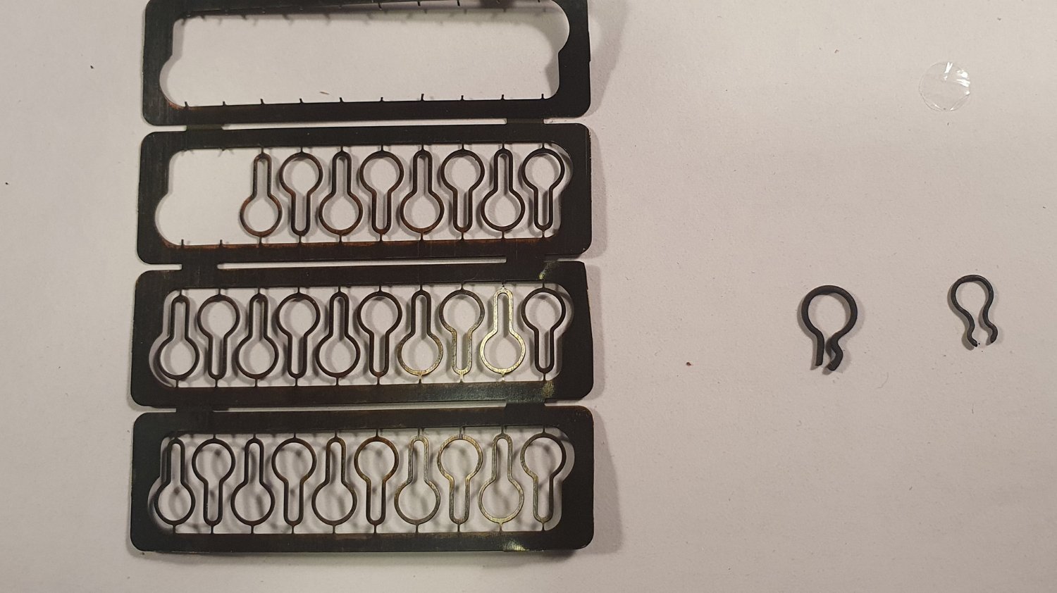
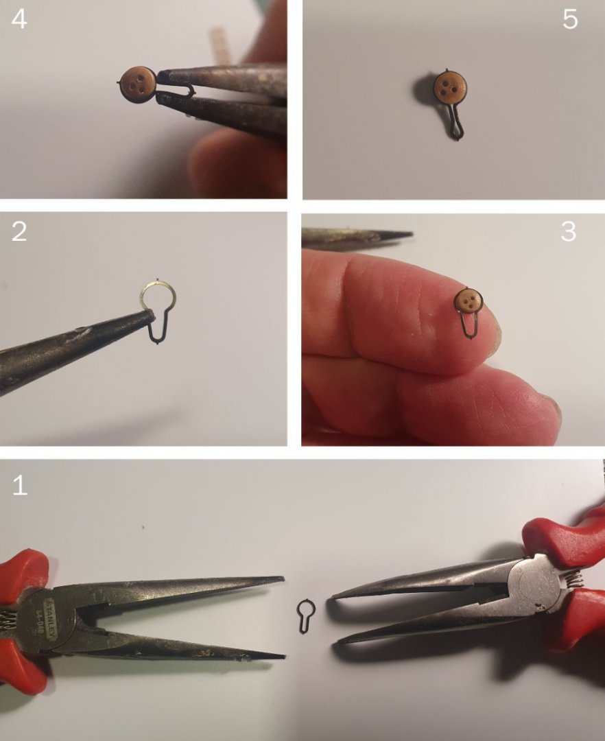
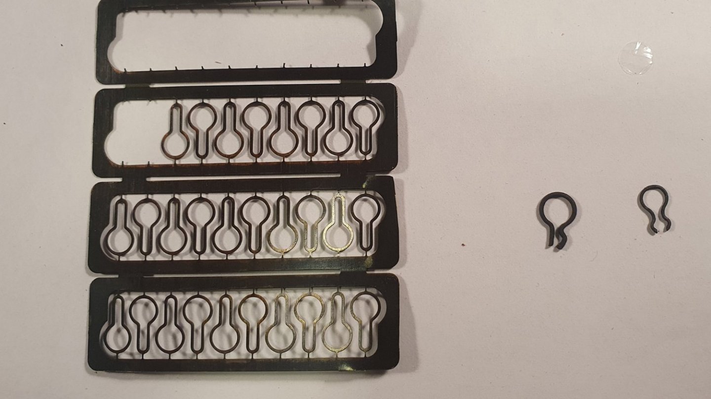
I have found this method works for me: 1. Take two pairs of pliers and gently open the strop. 2. Do not open too wide. 3. Wiggle the deadeye into place. 4. Gentle squeeze shut with the pliers 5. Deadeye should be able to rotate so as to position the holes for rigging
- 362 replies
-
- 4
-

-
-
- Amati
- Lady Nelson
- (and 2 more)
-
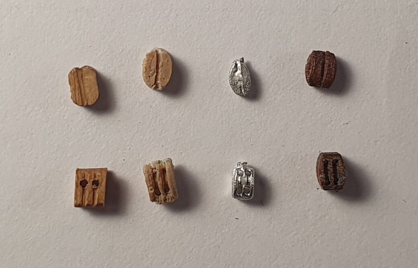
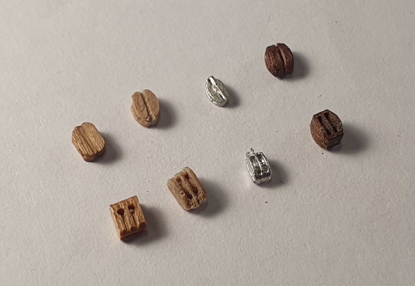
Thanks Dave. If you are considering upgrading the blocks for your forthcoming Diana build I would recommend pairing them with the 3mm hooks as the 5mm kit versions look a tad overscaled. Best regards, David
-
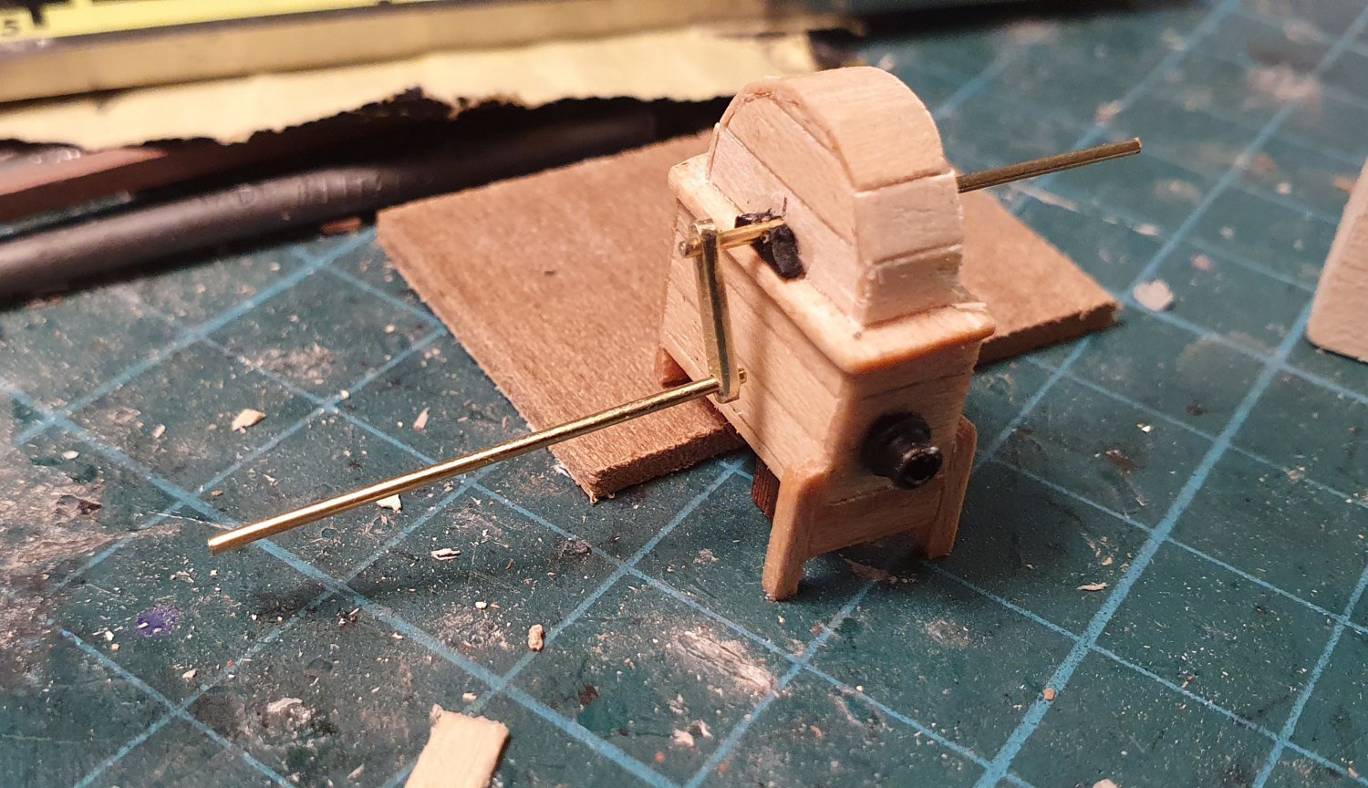
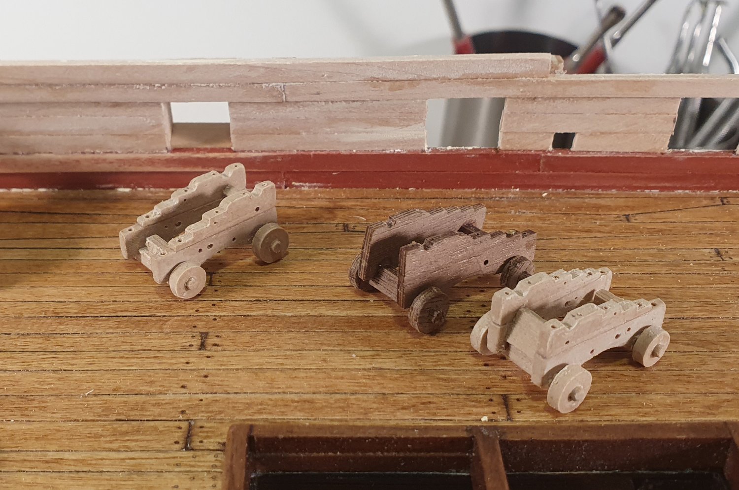
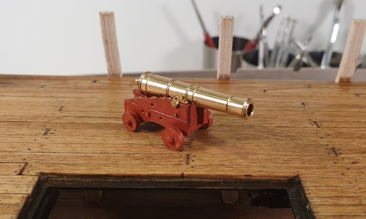
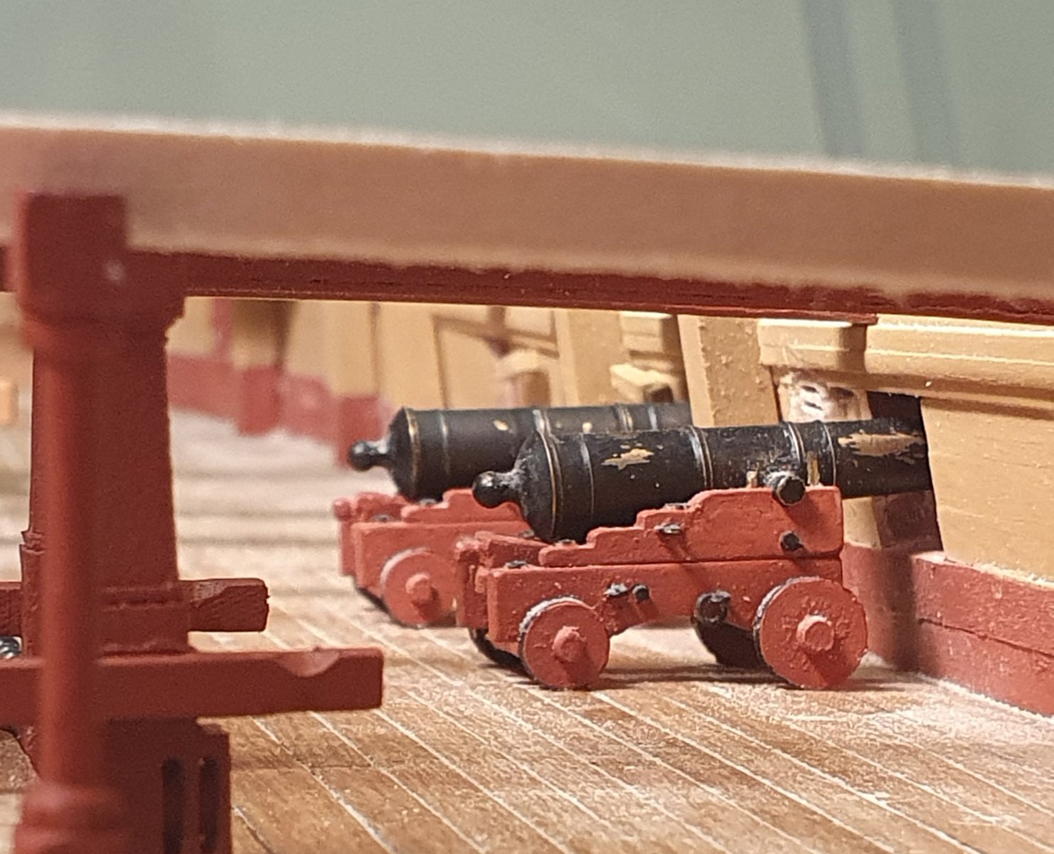
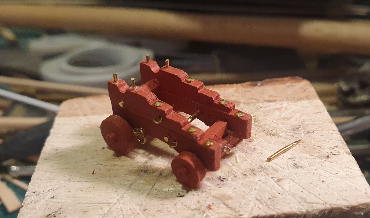
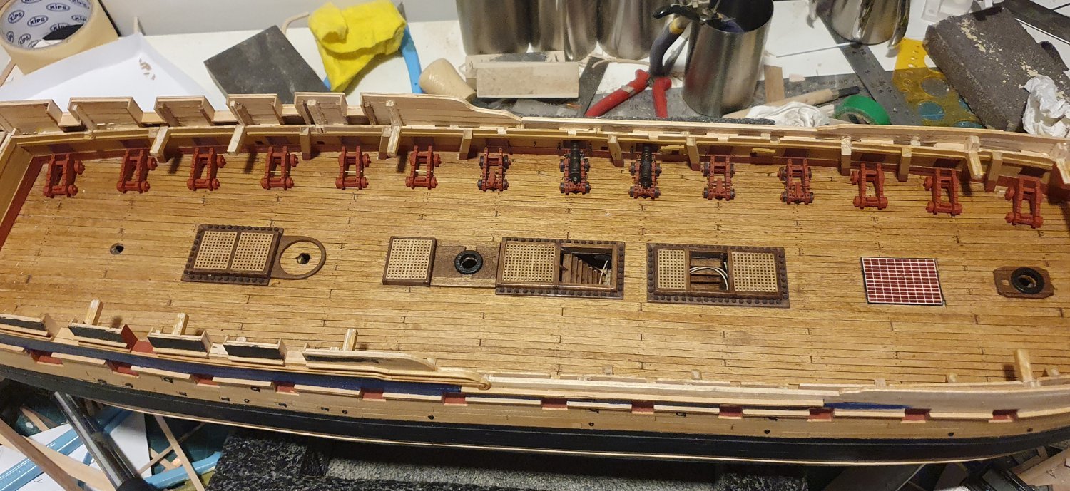
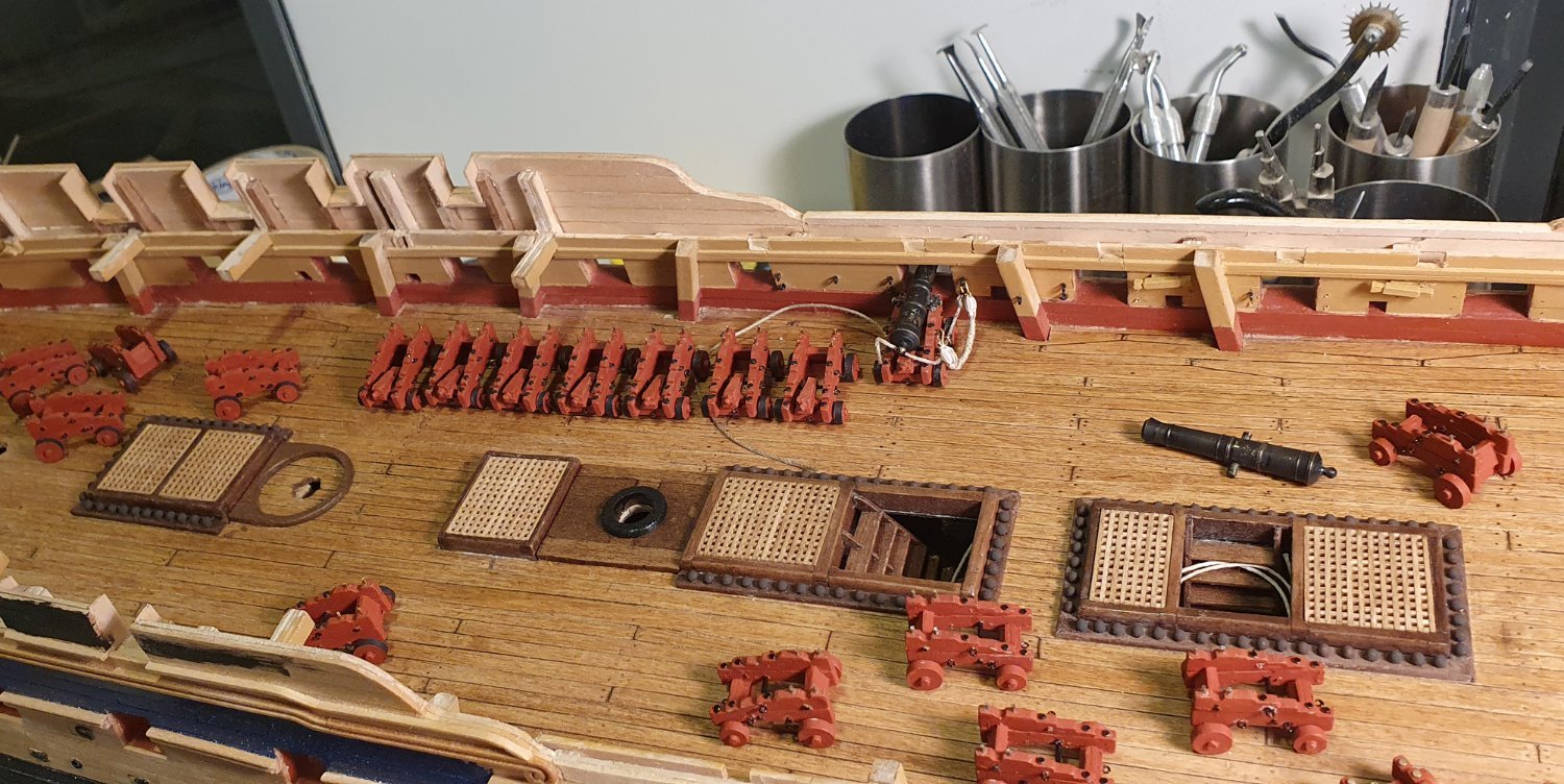
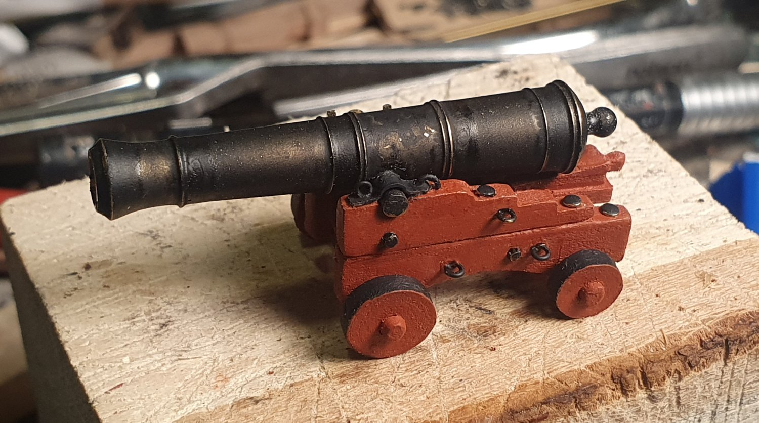
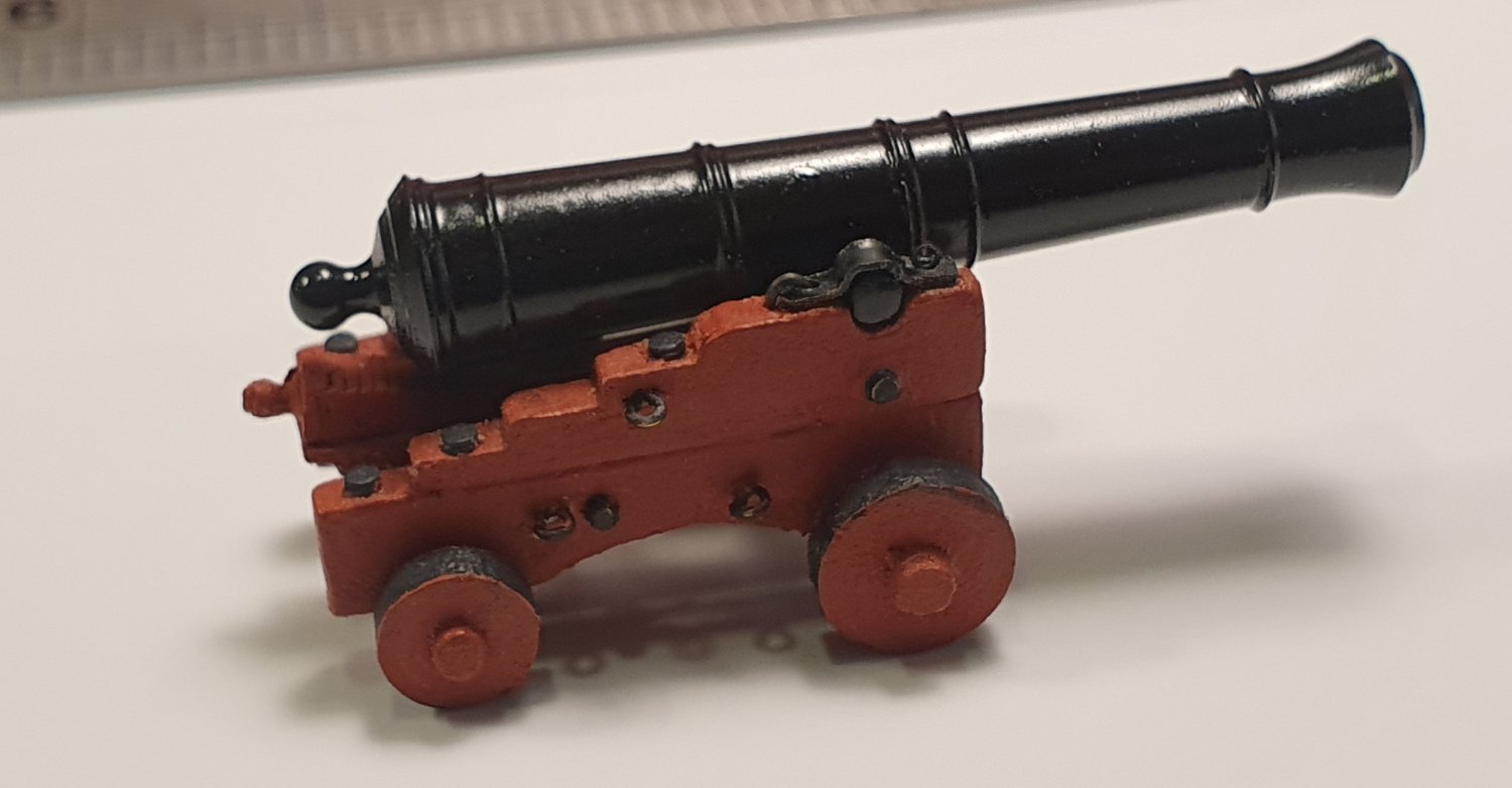
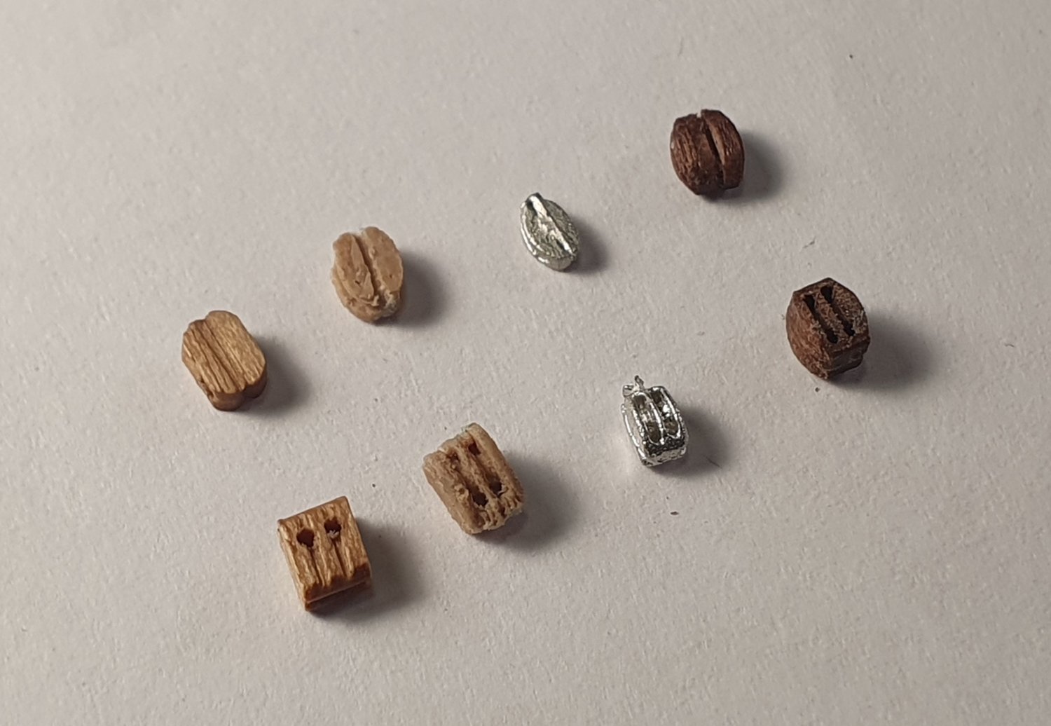
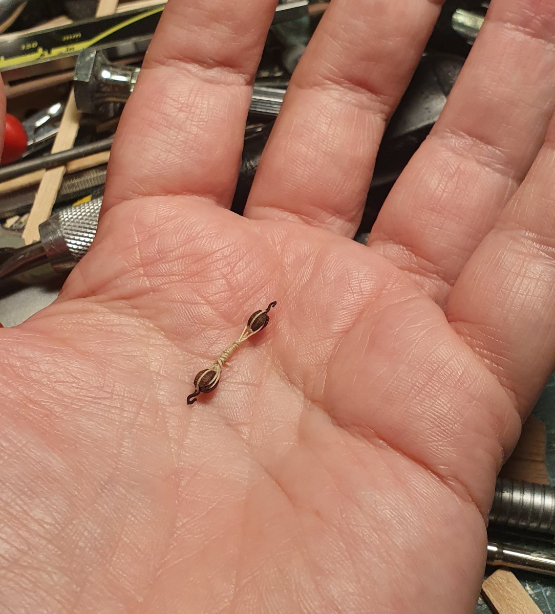
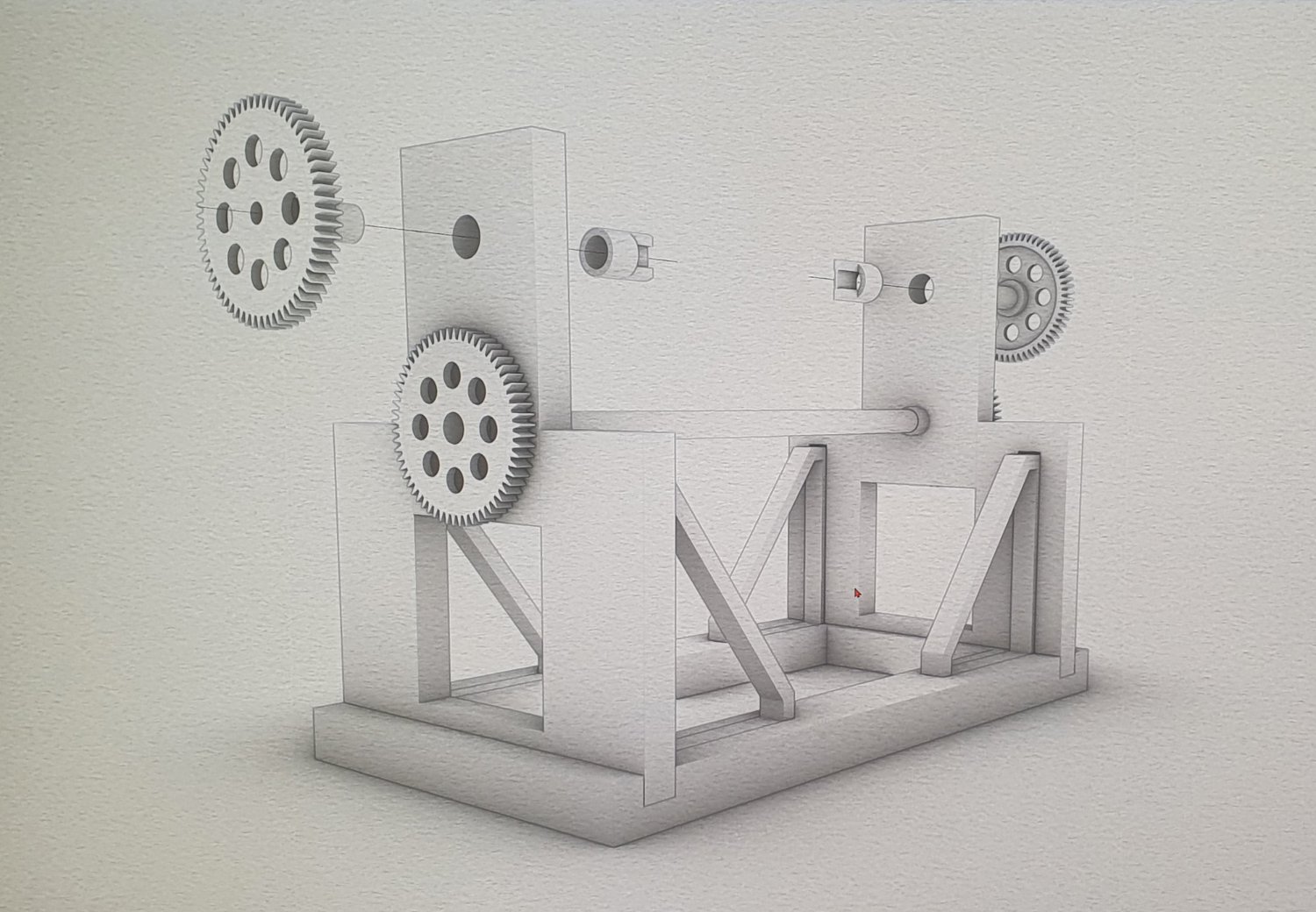
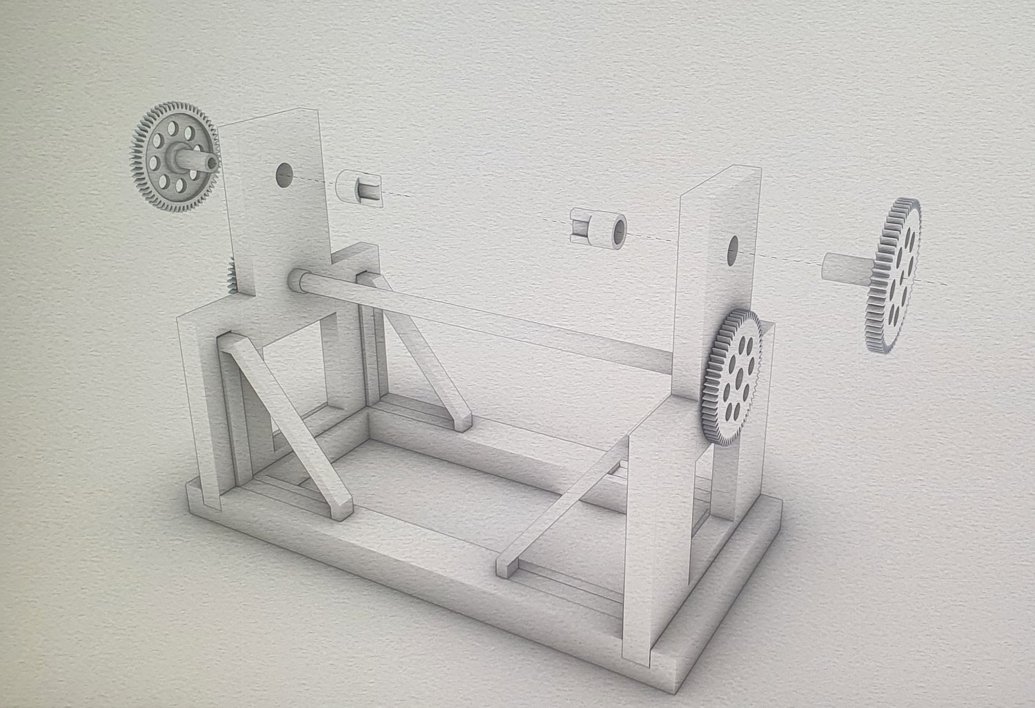
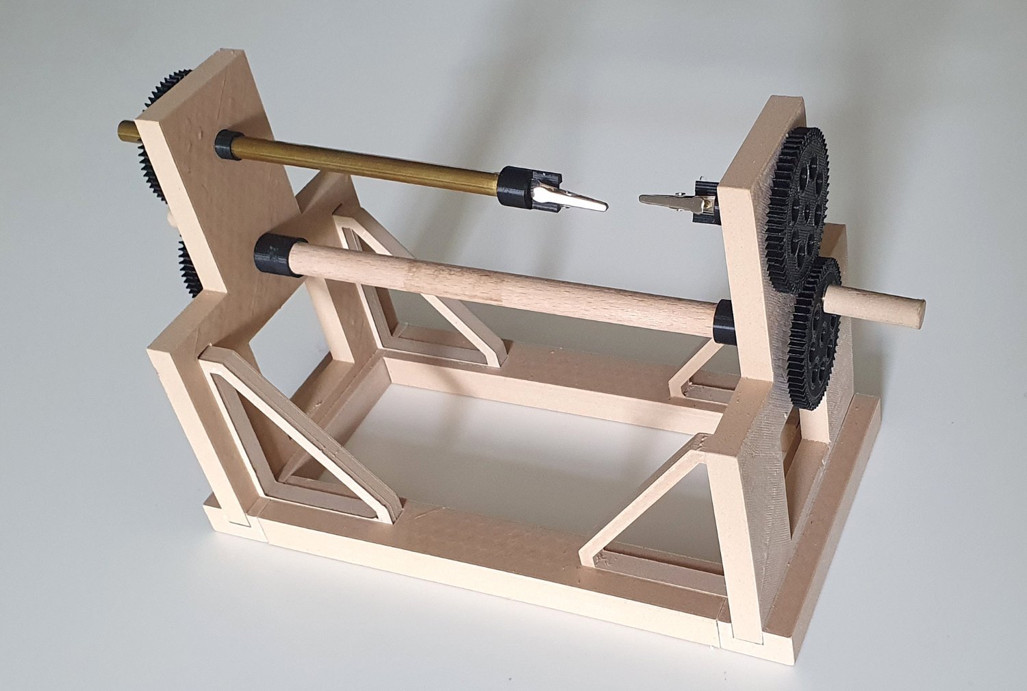
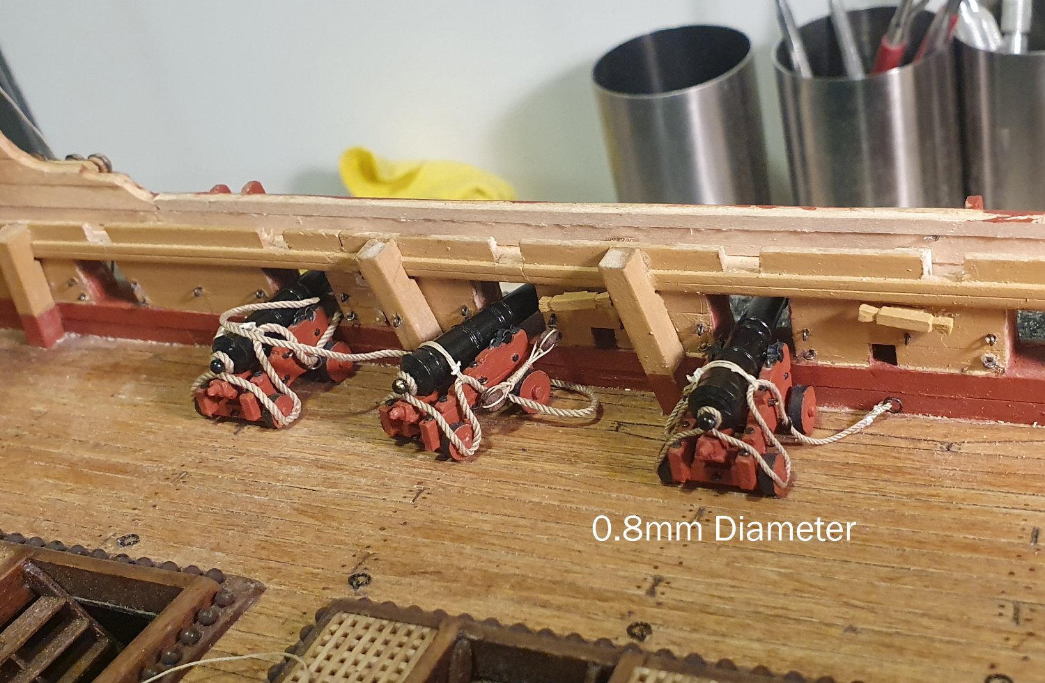
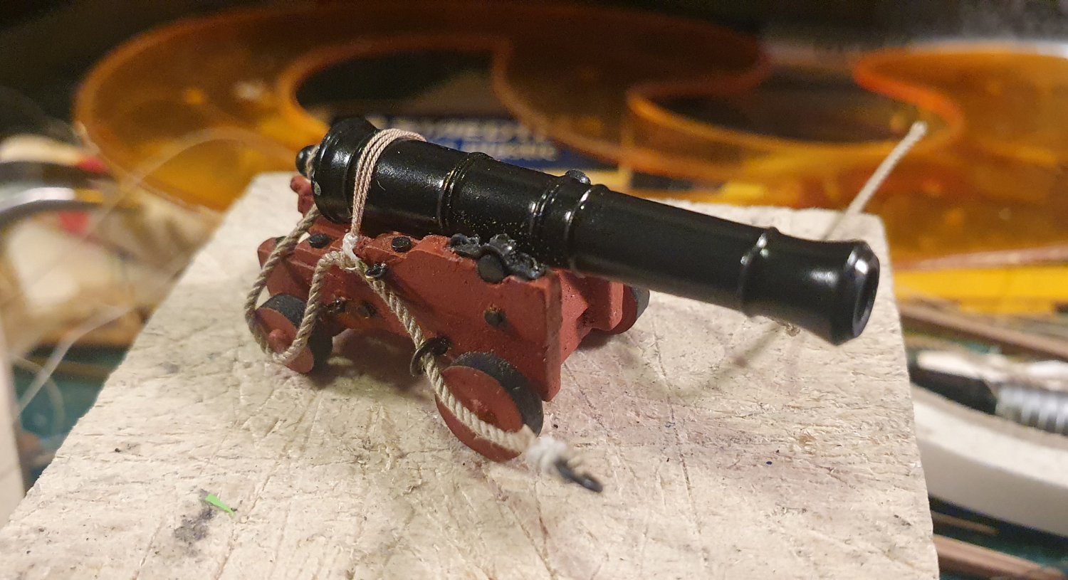
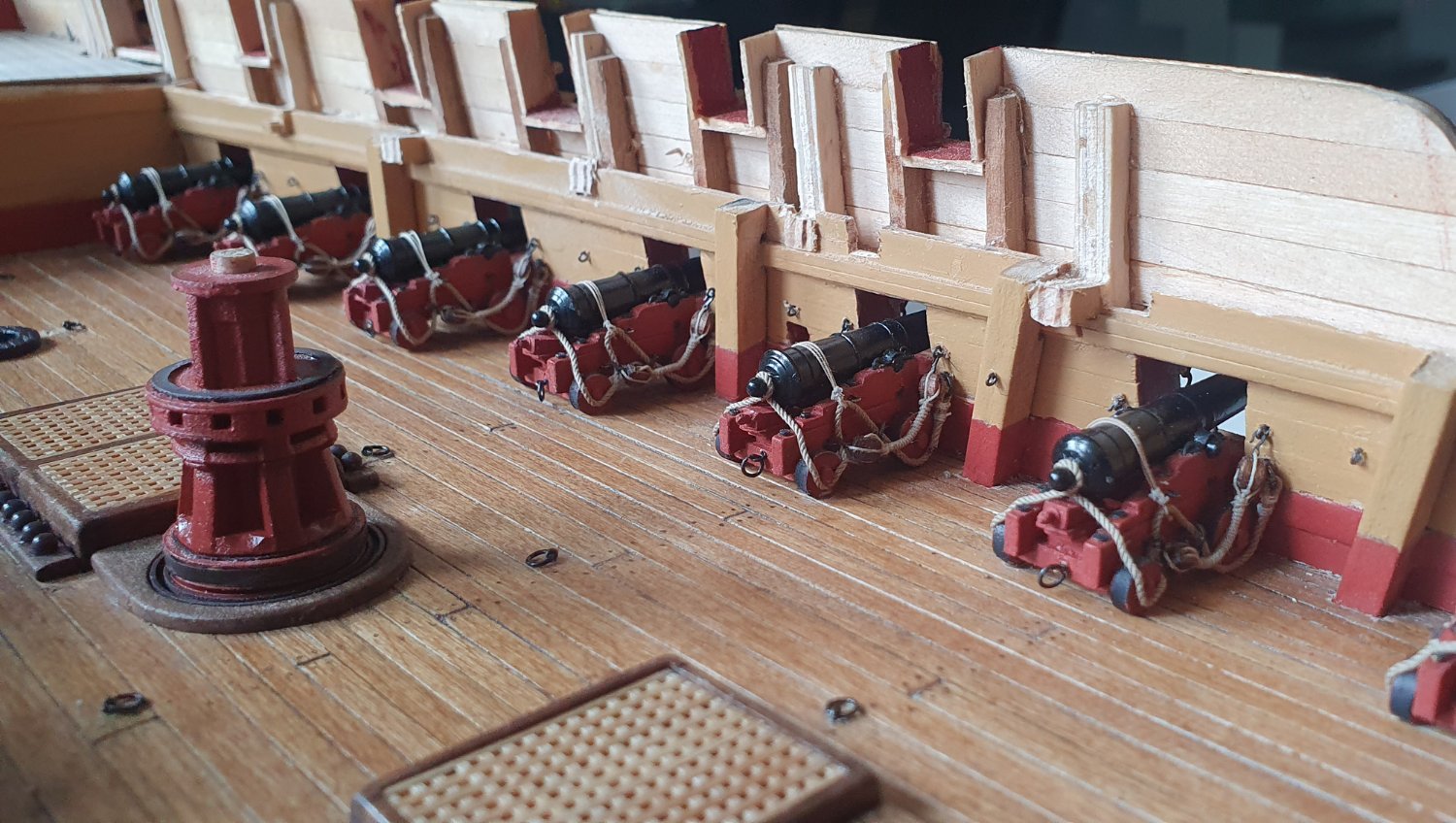
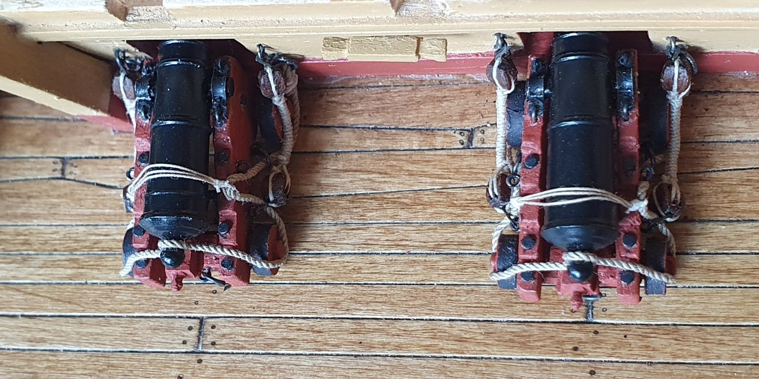
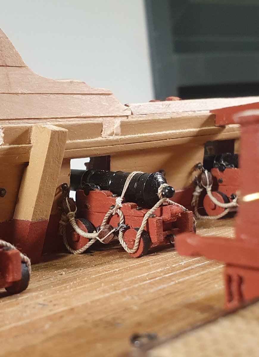
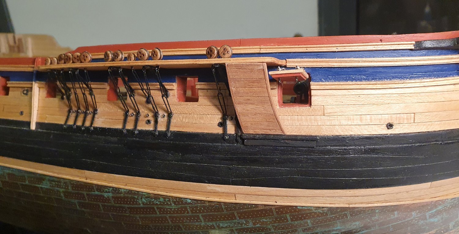
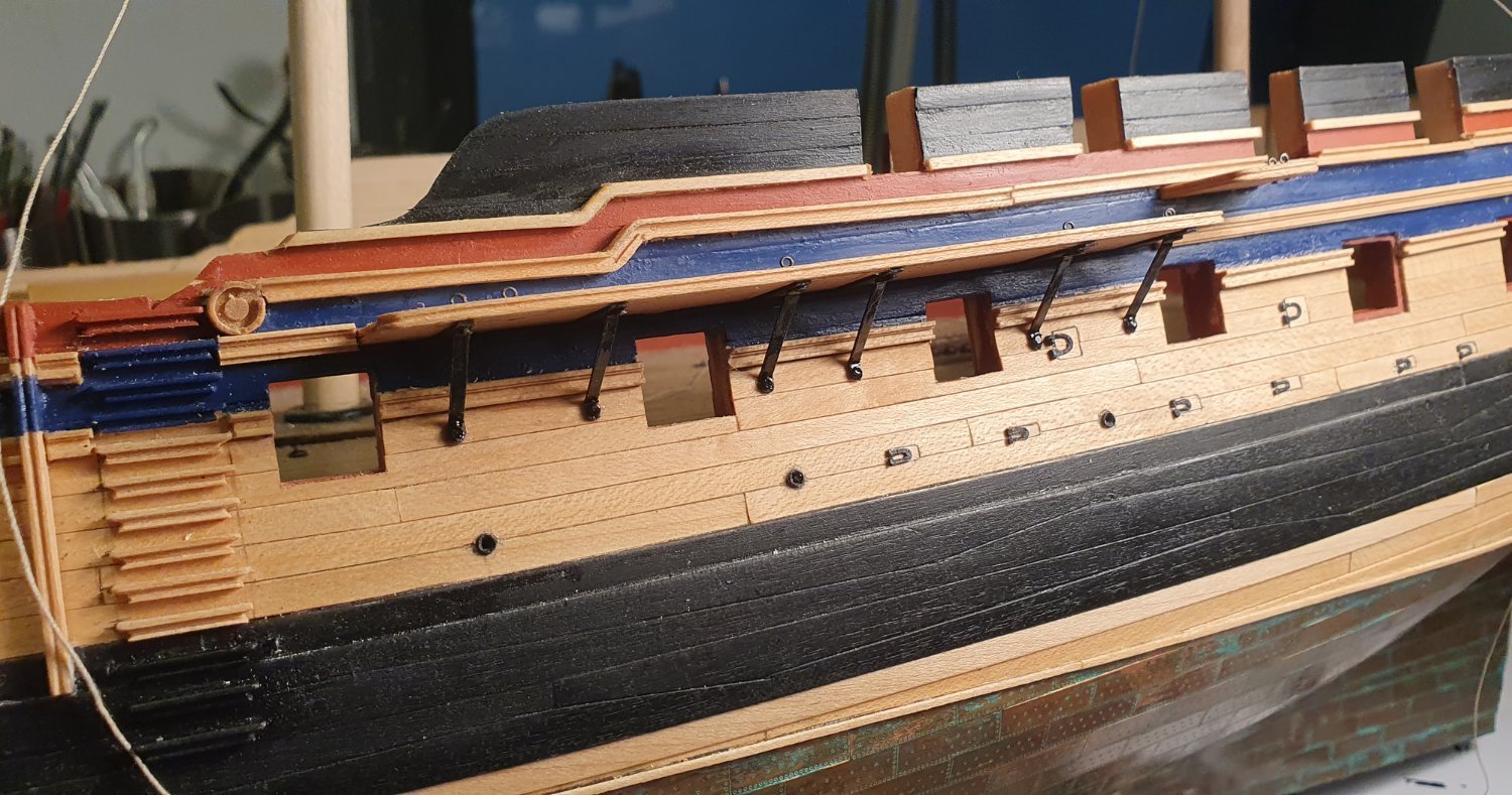
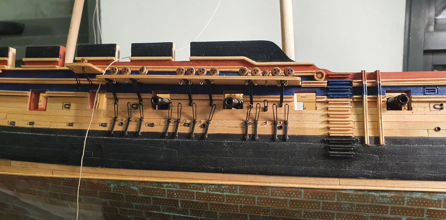
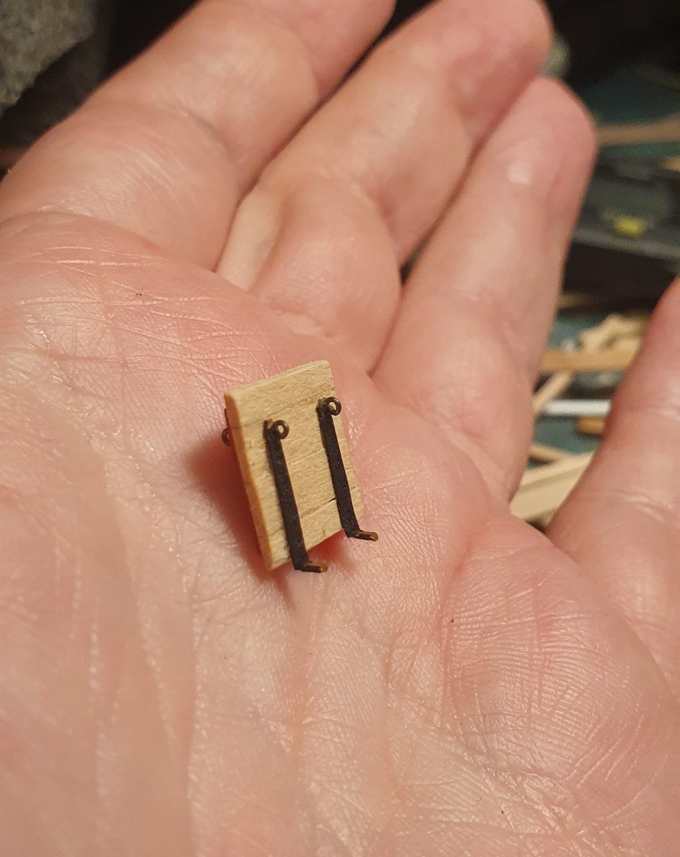
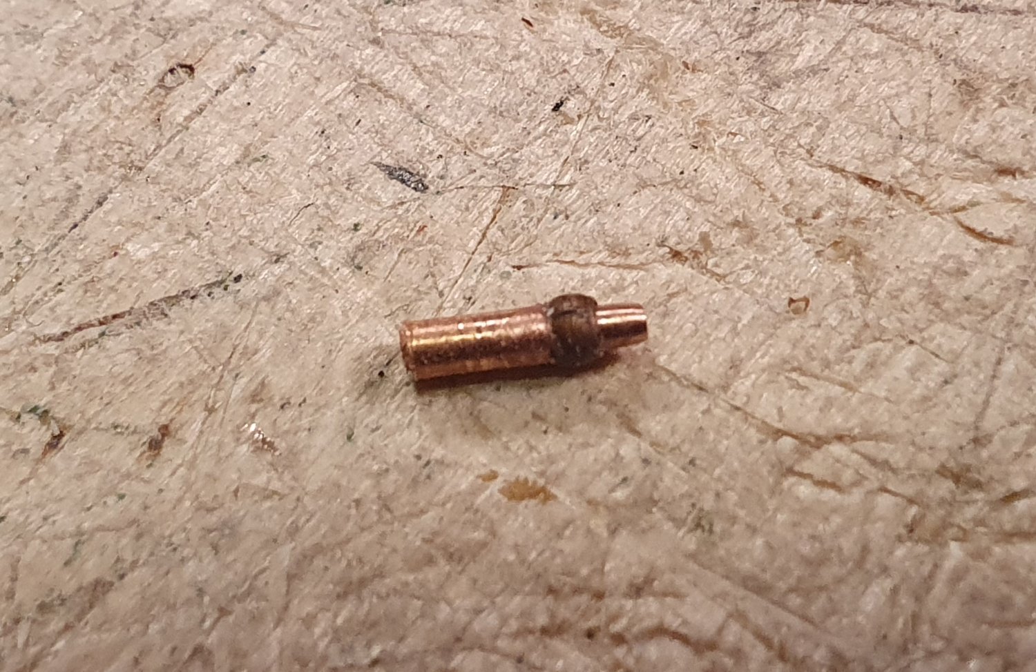
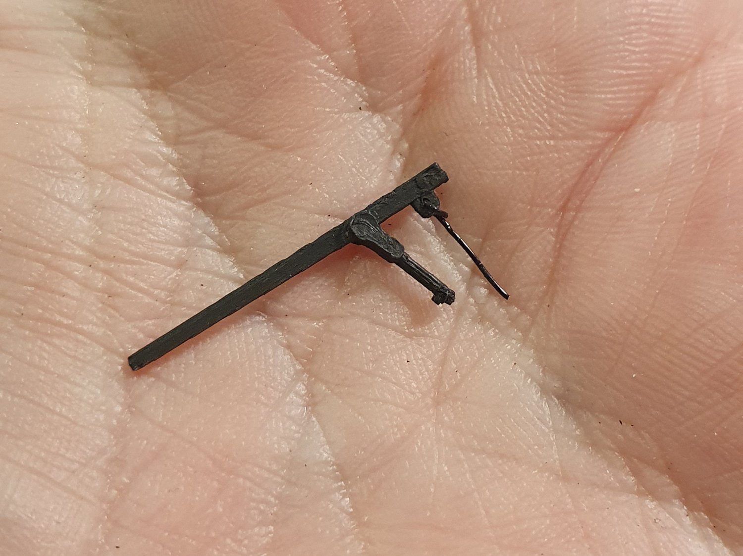
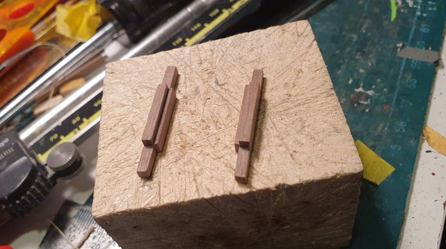
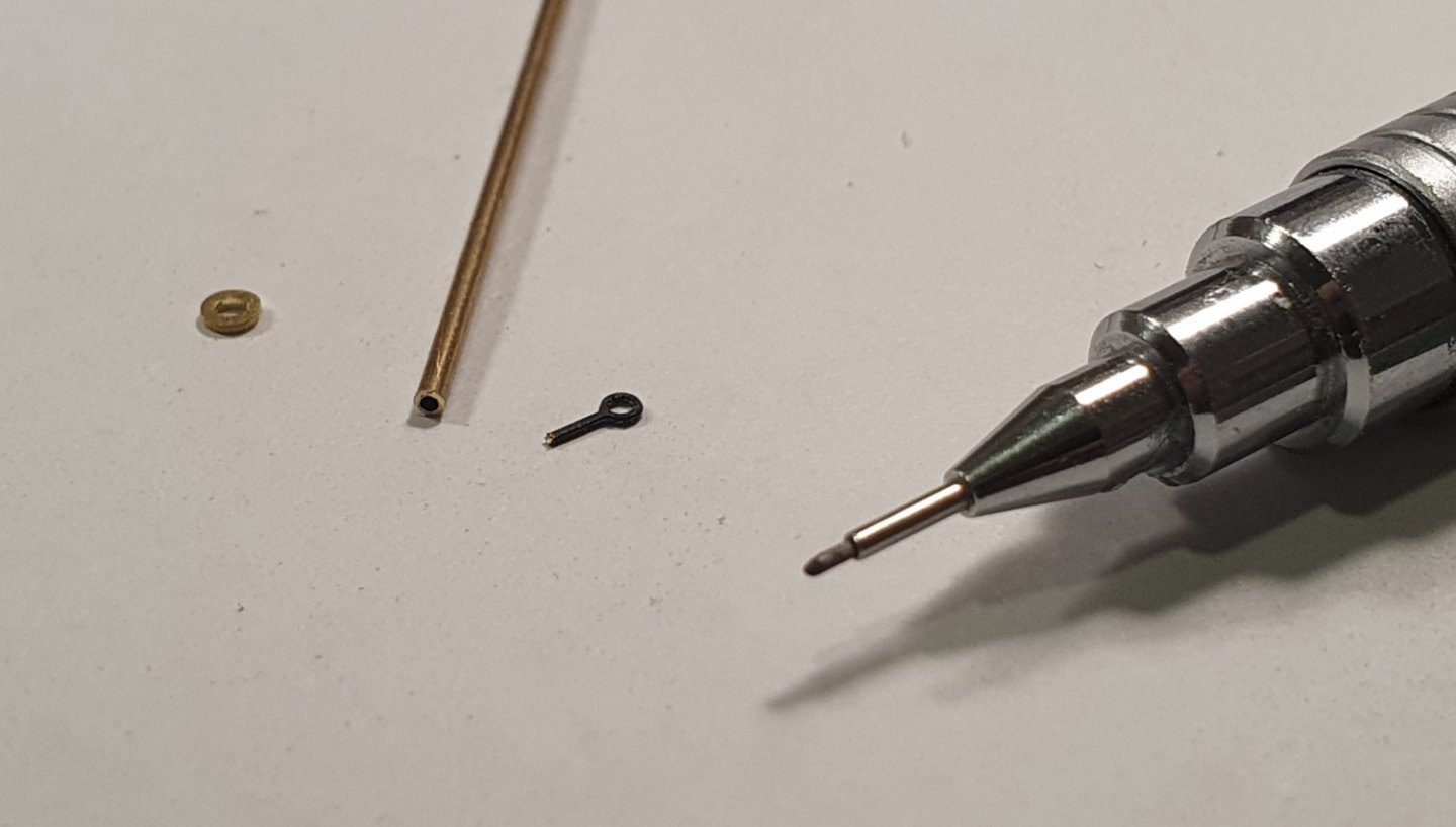
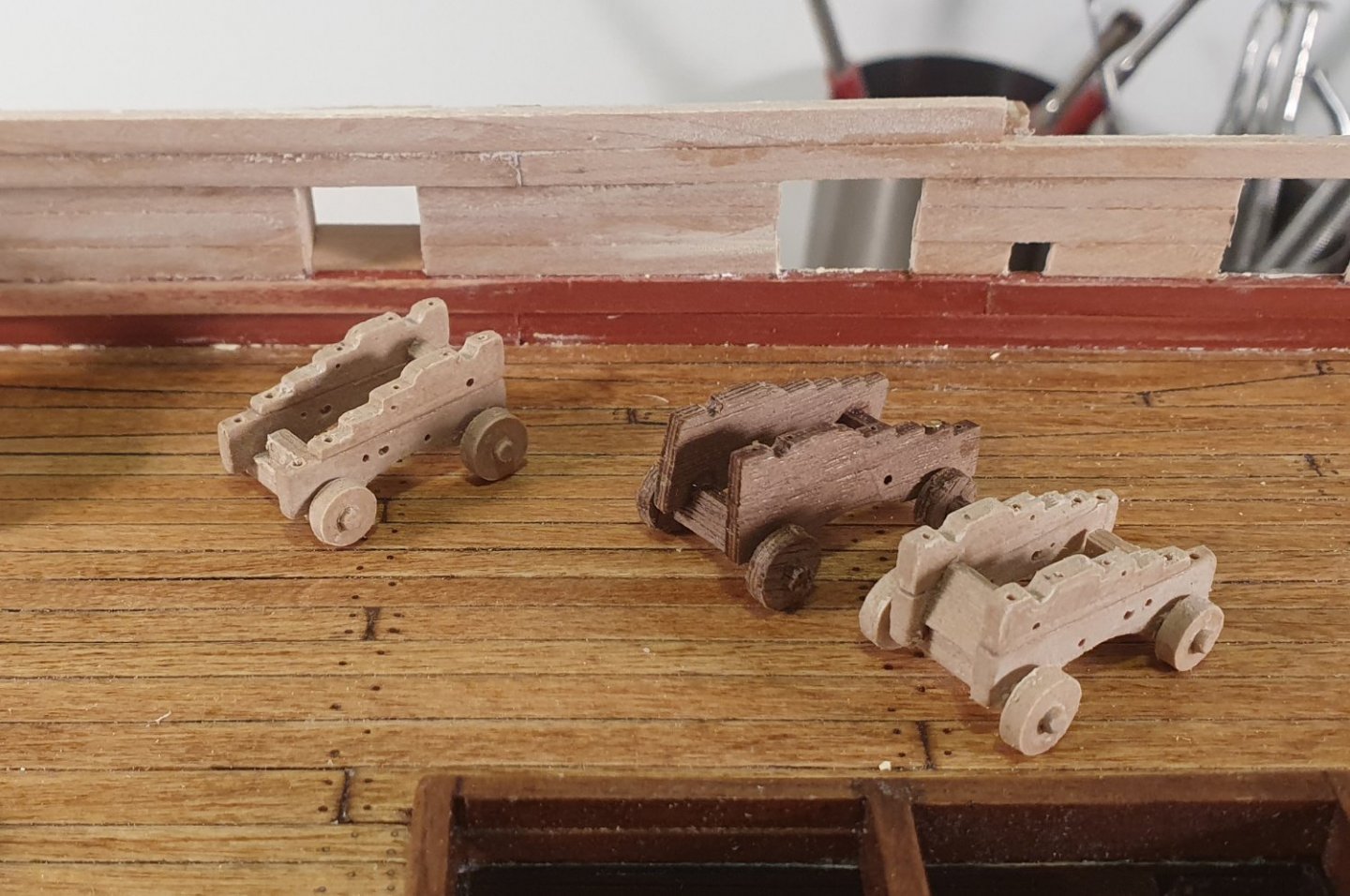
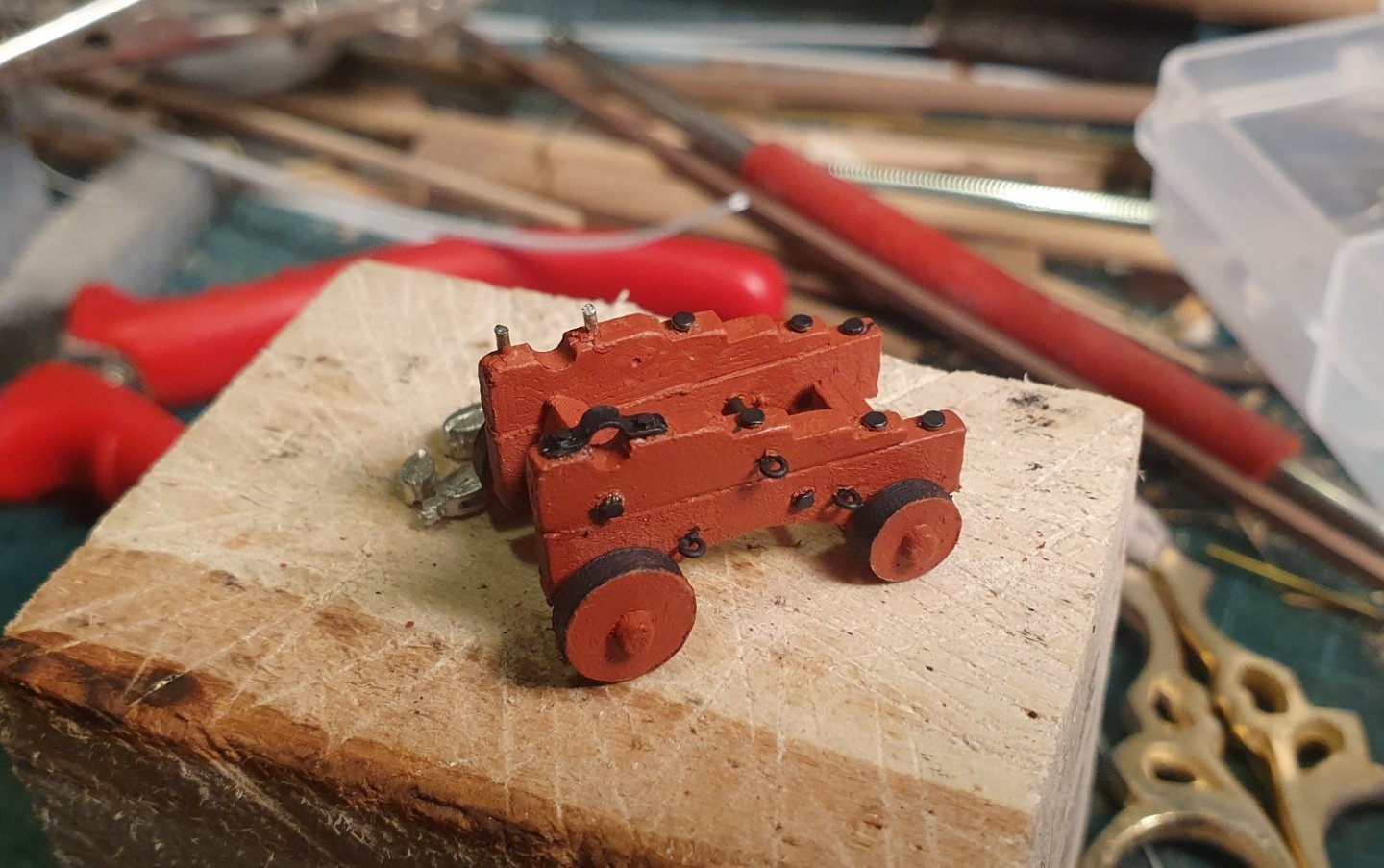
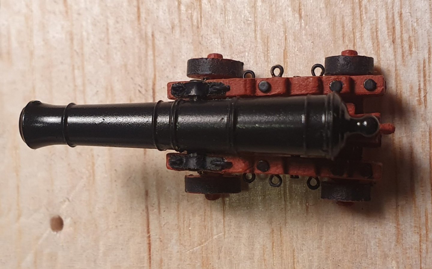
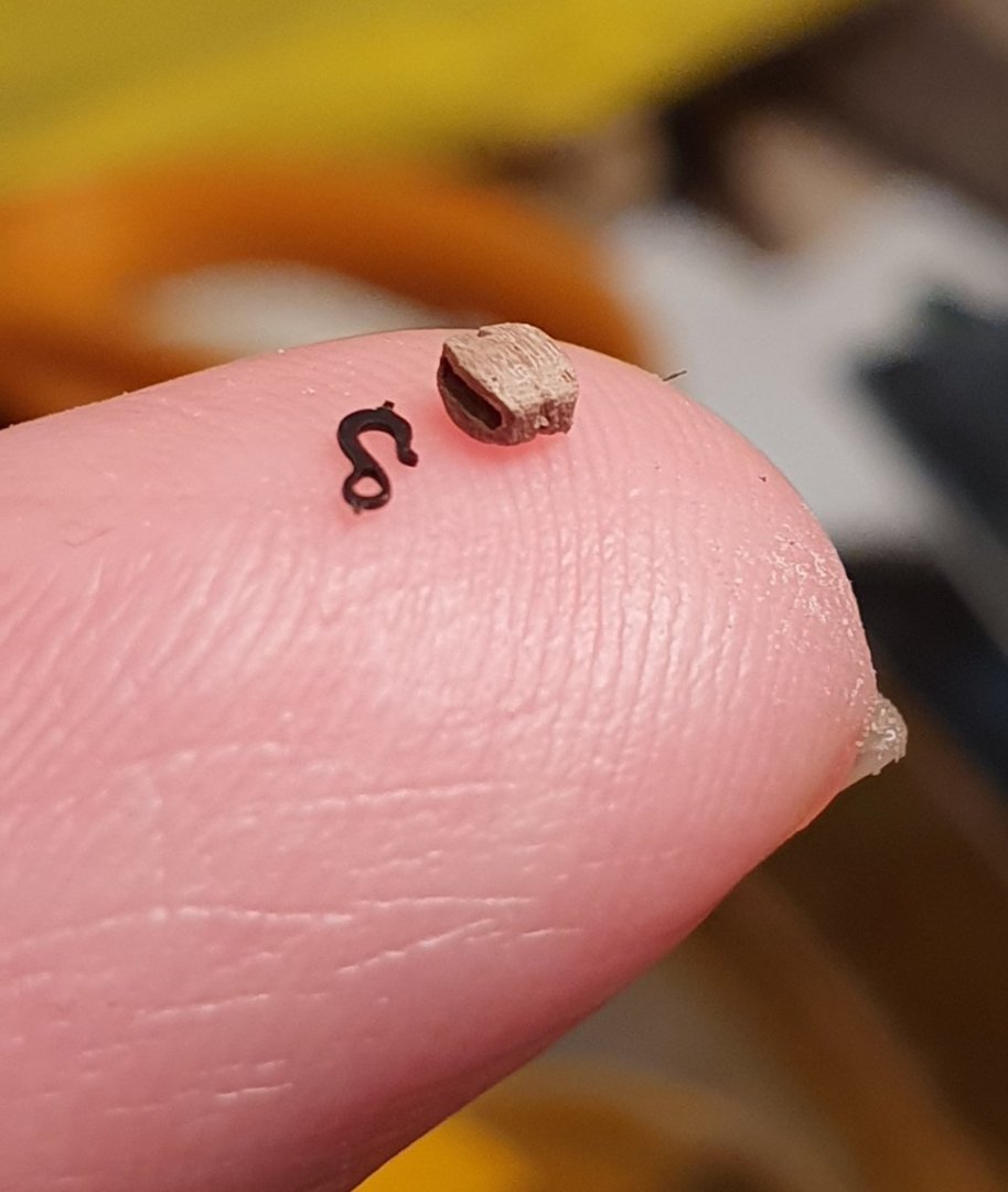
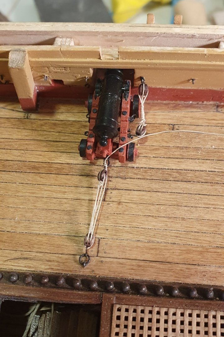
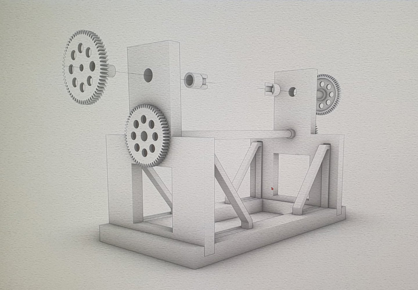
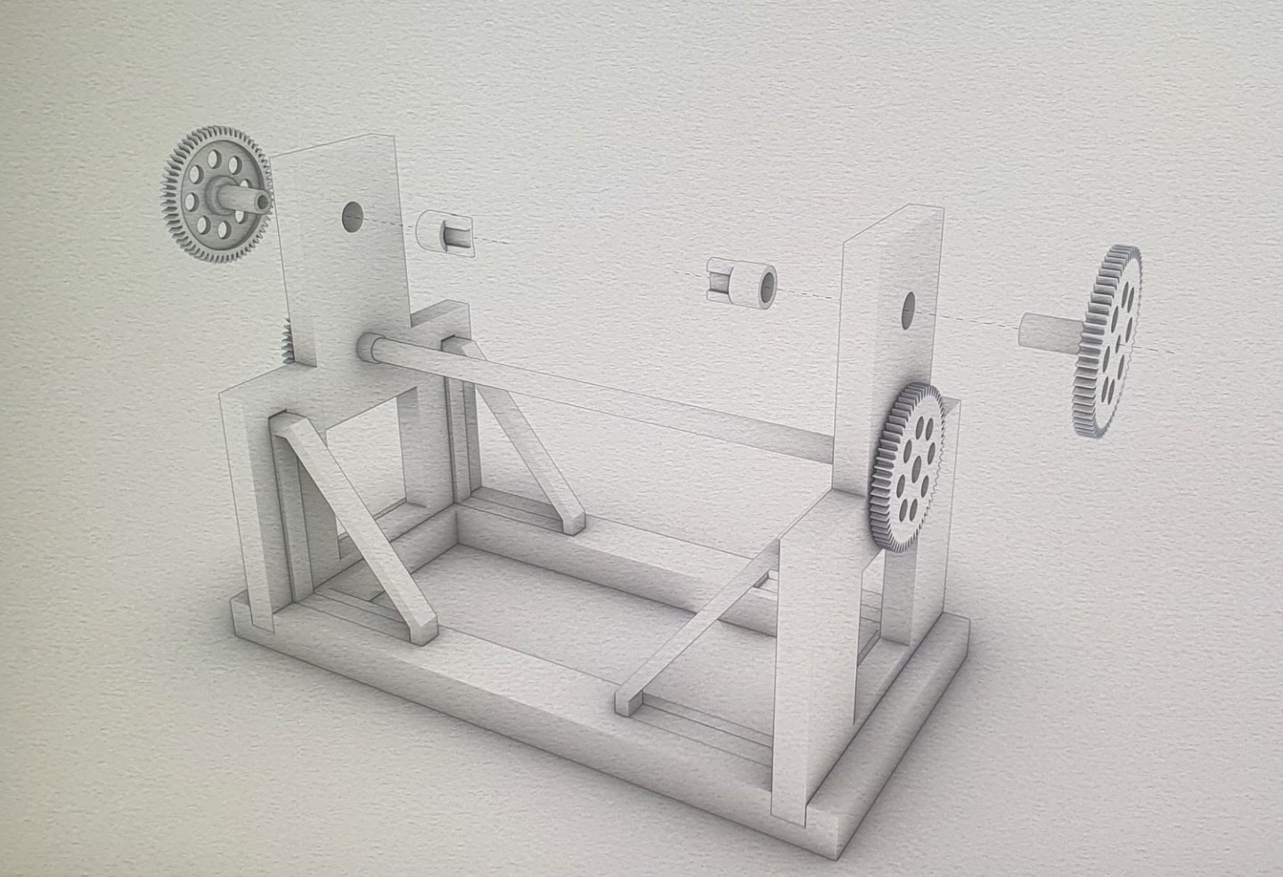
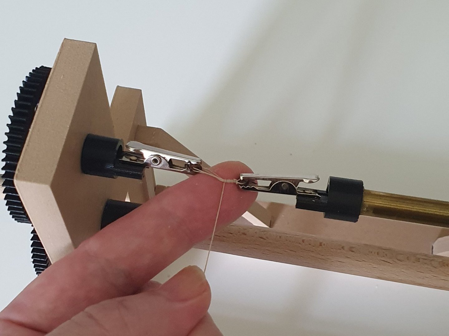
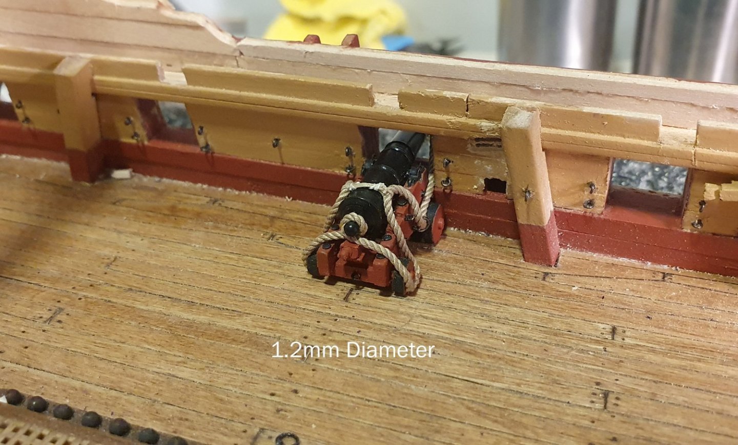
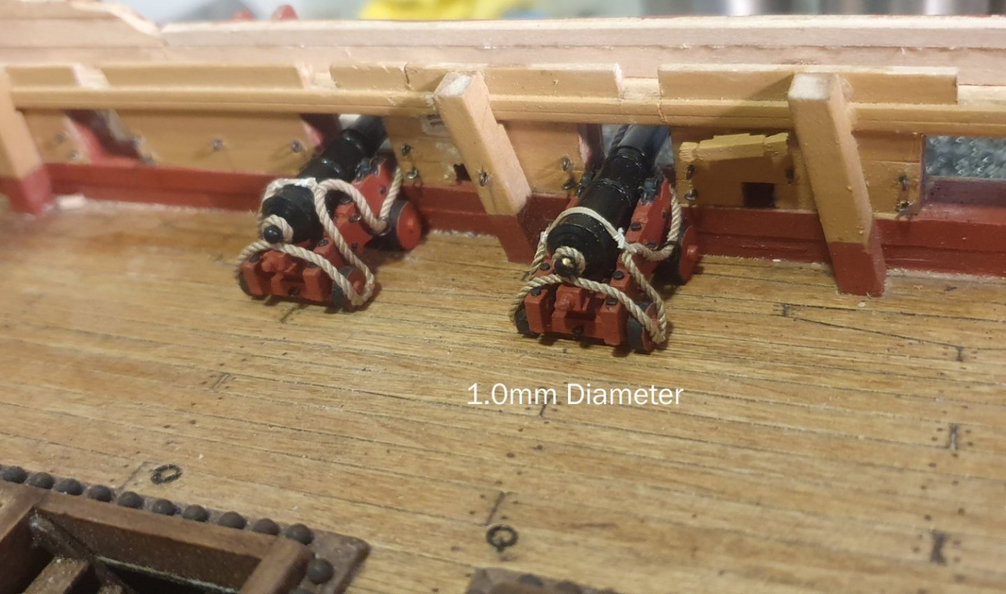
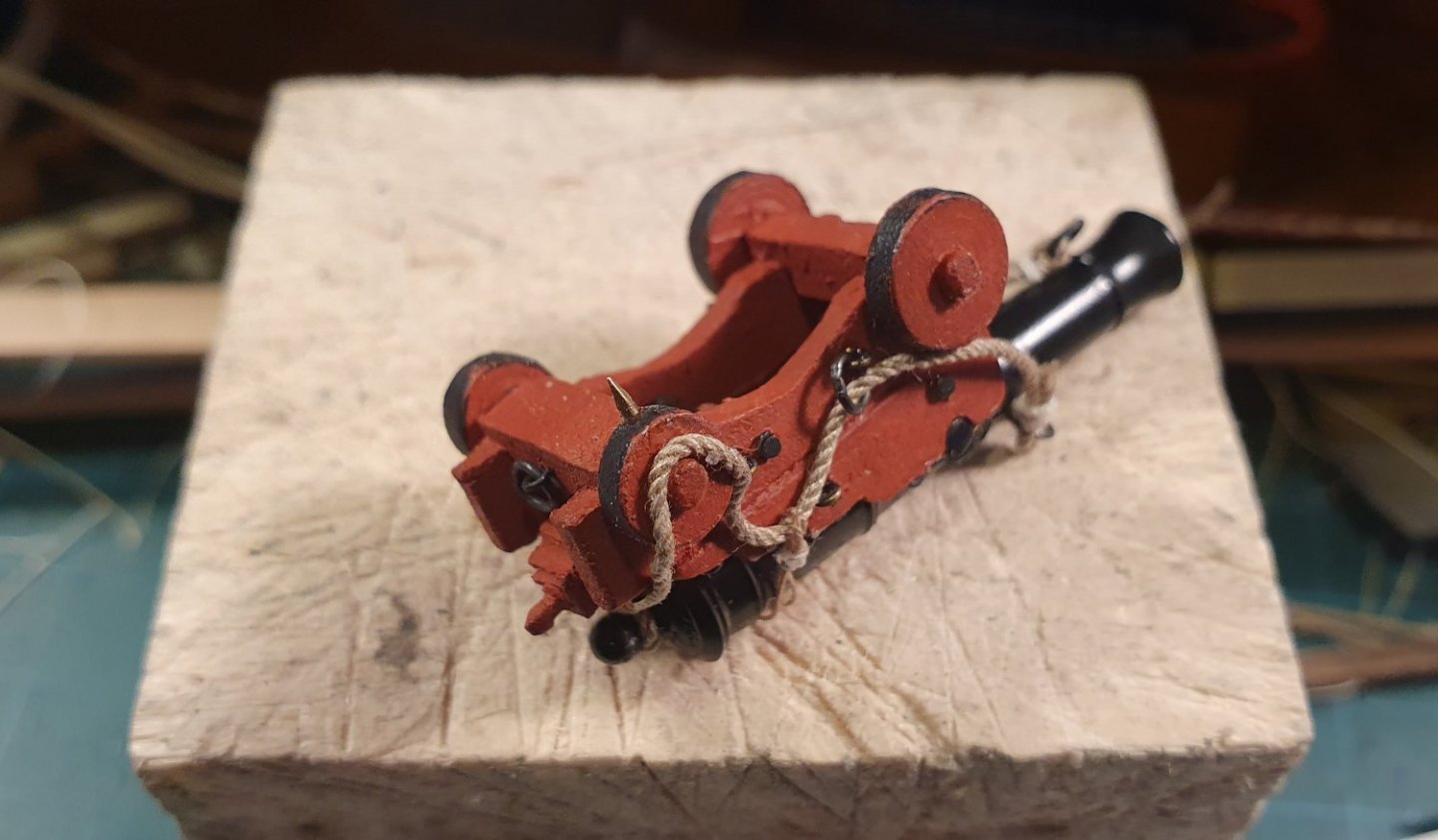
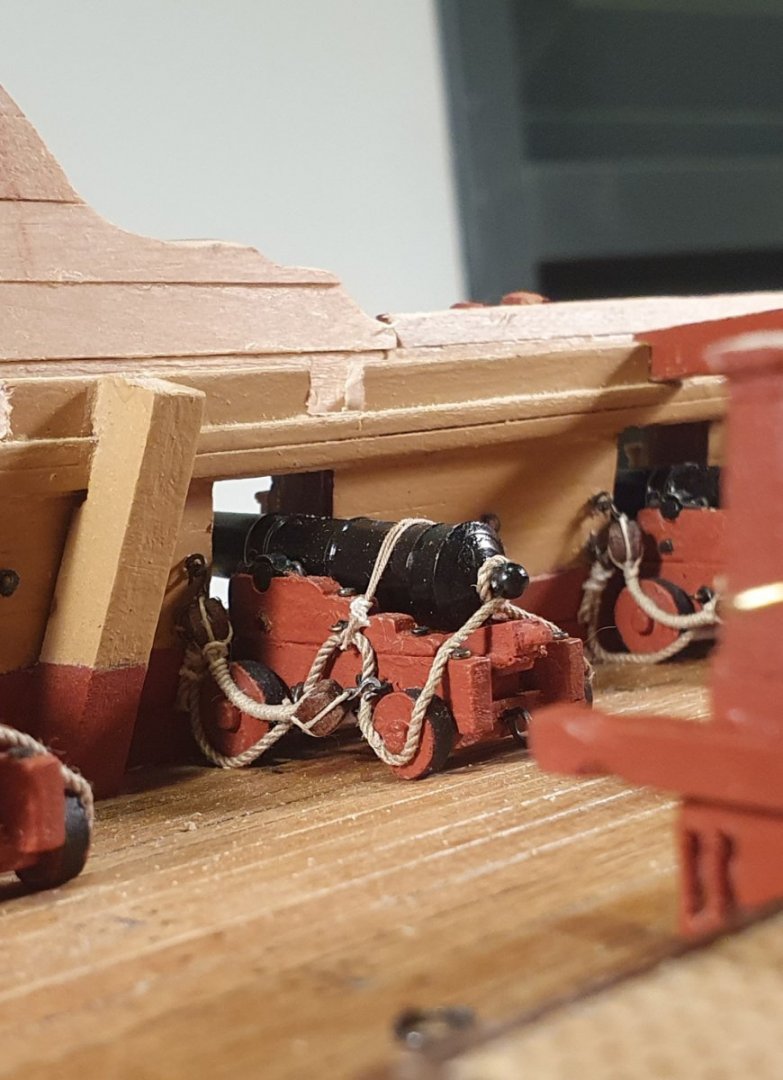
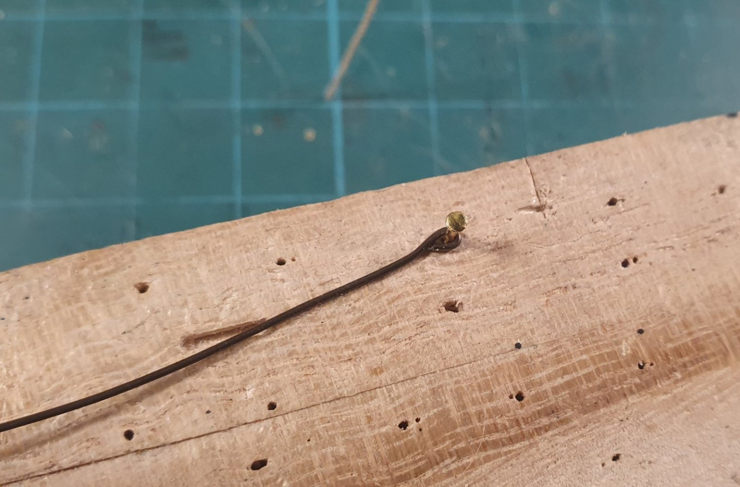
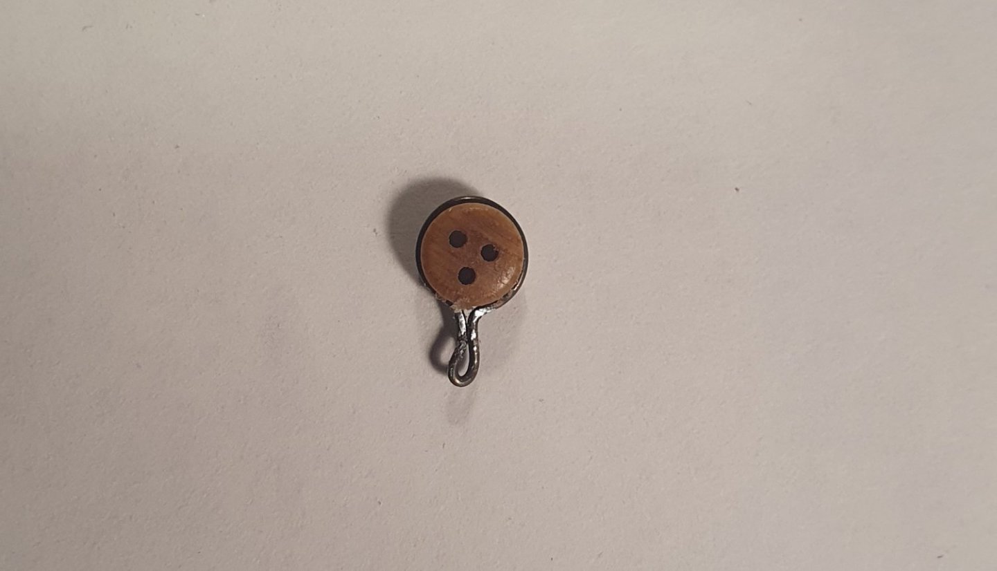
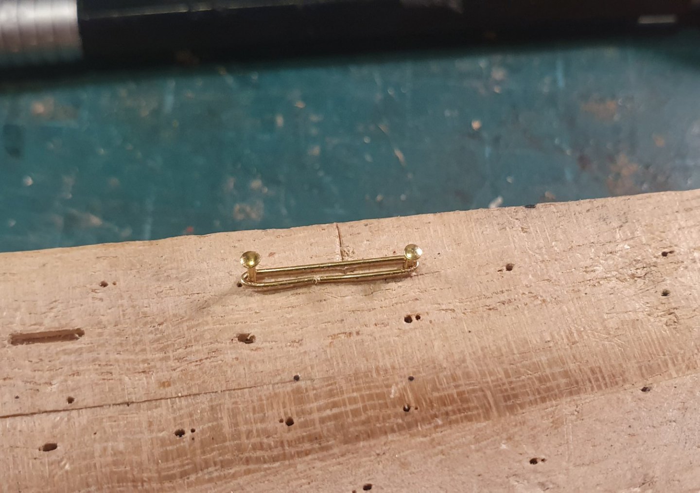
Time for the cannons. My previous build was a whaling ship so this will be my first cannon experience. I am probably more confident in the harpoon department. I started off building a carriage from the kit. I noticed that the side bracket was thinner than the dimensions shown in the AOTSD drawings so I decided to 3D print the carriages. I was considering going the same route with the barrels but the turned brass versions included in the kit were a good quality and dimensionally accurate. The only thing I did to these was to change the diameter of the trunnion from 1.5mm to 2mm. This necessitated drilling out all of the barrels but it is closer to the size indicated in the AOTSD drawings. I mocked up a couple of guns and noticed that the sat a little bit too low in the gunport. I attempted to remedy this by swapping out the front wheels with ones of a slightly larger diameter. I figured that they will not be too visible once all of the rigging is in place. I added the myriad of bolts and tackle loops using the heads of nails, nails without heads, eyebolts and brass rod. These were then all painted black which was a tedious activity. I have subsequently sourced some thin blackened annealed steel wire which could have saved me some build time. I had initially thought to use pins to fasten the capsquare which I would then trim and file down to simulate bolts but I eventually broke down and added a capsquare eyebolt out of brass wire and a capsquare joint bolt out of a photoetch eyebolt. I thought that the kit supplied blocks were quite poor so I started looking around for replacements. I examined 3D printing, cast metal and CNC milled varieties. I think that the CNC milled ones are the winner. Looking at the AOTSD drawings I went for a 3.5mm block which seemed about right. I initially ordered these from Vanguard models but the pesky post office conspired against me and the delivery was held up for a couple of months so I ordered some others from HiS Models. The Vanguard blocks eventually arrived and look quite good so I may use them for the upper deck cannons. I also sourced blackened photoetch hooks from HiS Models. These are 3mm long and much improved from the 5mm hooks included in the kit. The below photo shows a 3mm hook alongside a 2mm block resting on my fingertip. If you drop either of those on the floor there is a good chance you are not getting them back. It was with some trepidation that I prepared the post concerning the cannon rigging as I have noticed that nothing jolts the aggrieved pedant from their fitful slumber than historically contentious cannon rigging. I decided to model my cannon rigging on the photographs of examples on restored ships. I am aware that a lot of this is done to prevent lawsuits served by lumbering tourists tripping over ropes but I like the neat look with the port and starboard tackles frapped and the breech ropes lashed over the top of the barrel but without the relieving tackle to prevent deck clutter. The model is destined for a shelf in the house and not a museum so I can make such wilful decisions. Seeing as I had to complete the frapping on 56 tackles I decided to build a basic serving machine to help me speed up the task and achieve a more uniform result. I designed and built the device using CAD and the 3D printer. Not the most elegant of solutions but it worked after a fashion although the design of the machine requires a lot of tweaking. It was meant to be adjustable with the upper brass tube able to slide back and forth but I should have made the entire support structure move to reduce the amount of play at the clip end. I purchased around five different types of rope for the breeching but none of them were satisfactory. I eventually found the Ropes of Scale website from a reference on Dunnock's Diana build log and their ropes are a lot better than any of the others that I procured. I noticed that most of the breech ropes that I have seen in photographs are quite substantial. I experimented with different diameters starting with 1.2mm diameter which was too big. I then tried 1mm diameter which didn't look too bad but I discovered that the 0.8mm diameter rope corresponded to the actual dimension used so that had to be the winner. I rigged the cannon by fixing the breeching rope to the cannon before fixing it to the model. The rings at the end of the breeching are also added at this stage. I just did a simple seizing as I couldn't get a satisfactory knot. I then drilled and glued a pin in the rear wheel of the carriage which was inserted into a pre-drilled hole on the deck. I thought this would give me a more secure fixing as I imagined I would eventually knock some of the barrels while working on the rest of the ship and it would be very difficult to recover a cannon that had become loose under one of the upper decks. The rigging was then attached to eyebolts that I had previously installed in the bulwarks. It took a while but once I got a rhythm going the installation went fairly quickly so I carried on and ended up rigging all of the cannons and not just the visible ones. I still have not mastered the art of getting the ropes to hang naturally but I am hoping that will come with practice. I am also not too happy with the finish on the 3D printed carriages and will be looking to experiment with more of a timber/3D printed hybrid when it comes to the cannons located on the upper deck.


-
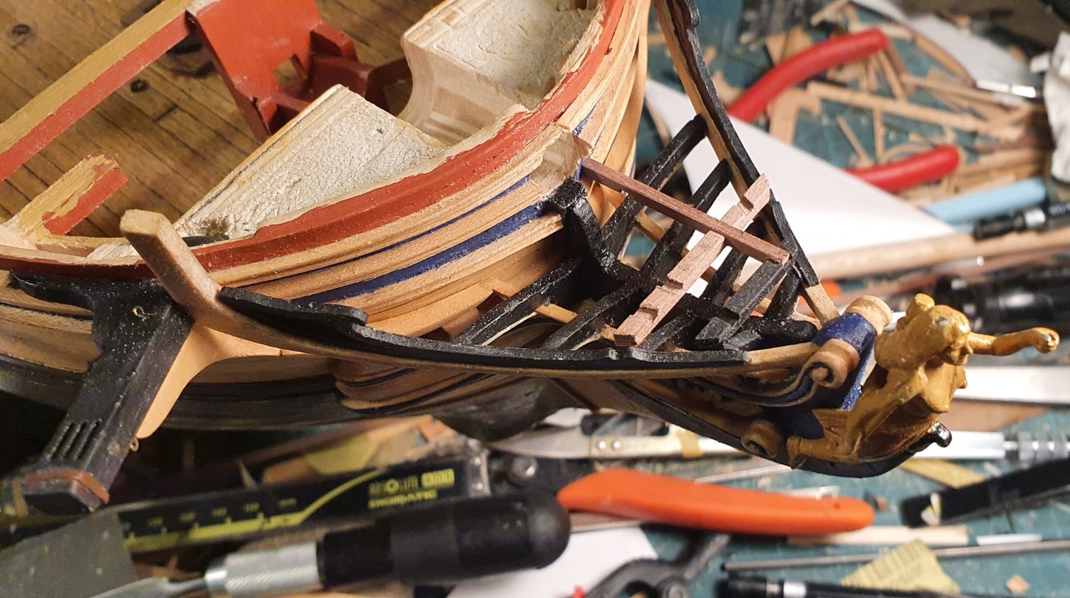
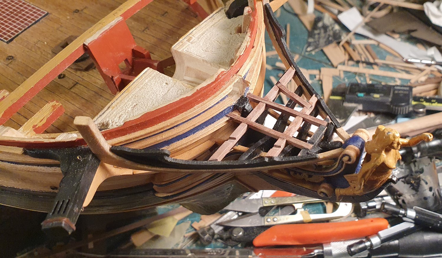
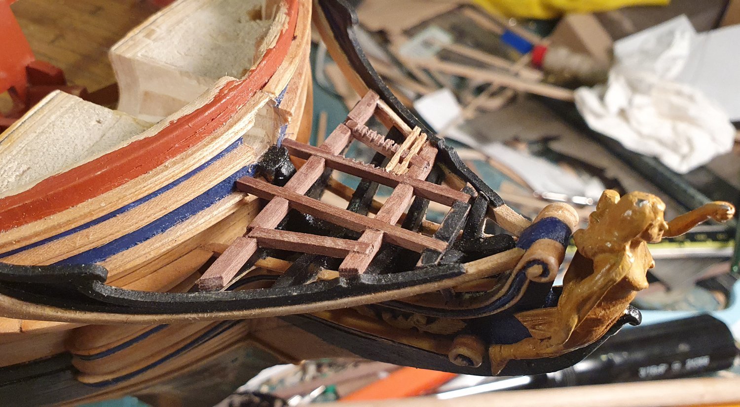
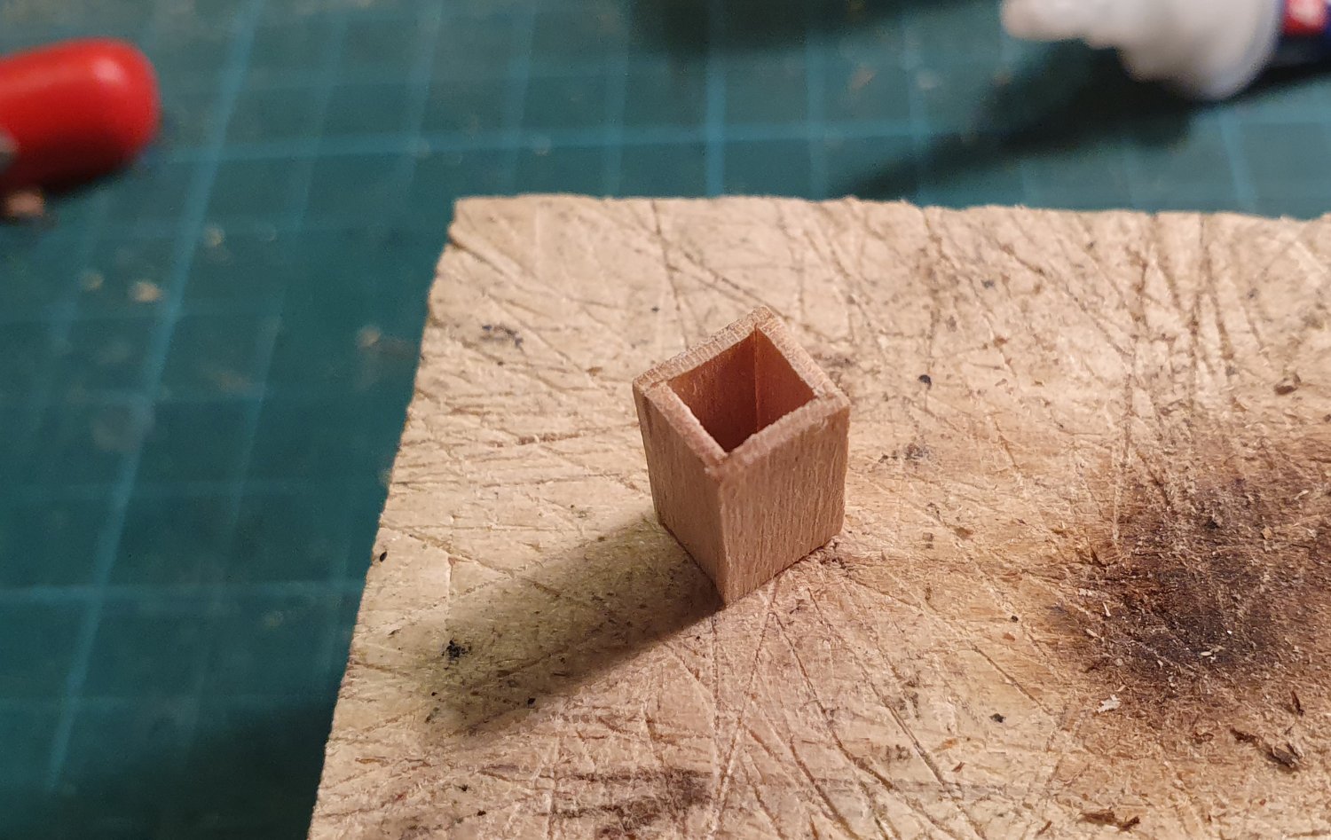
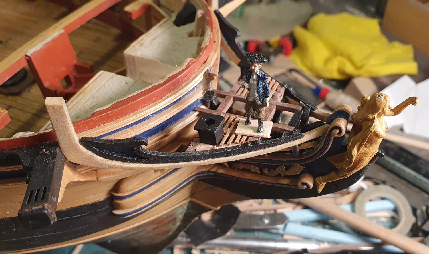
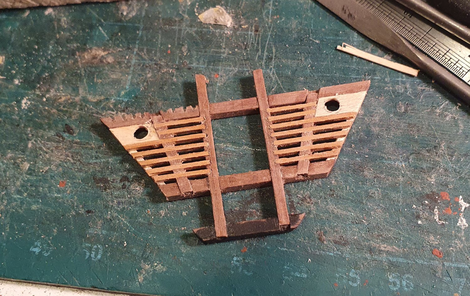
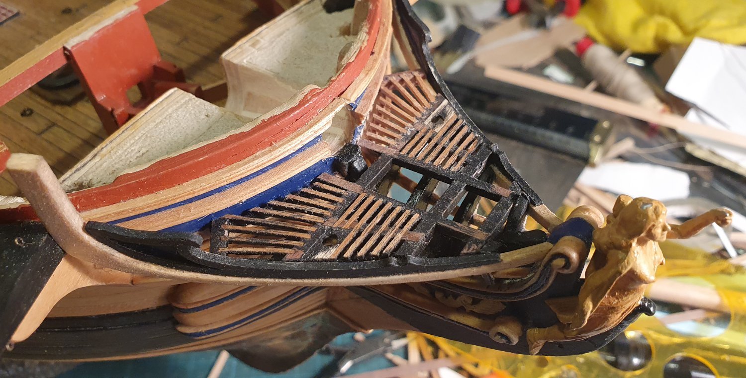
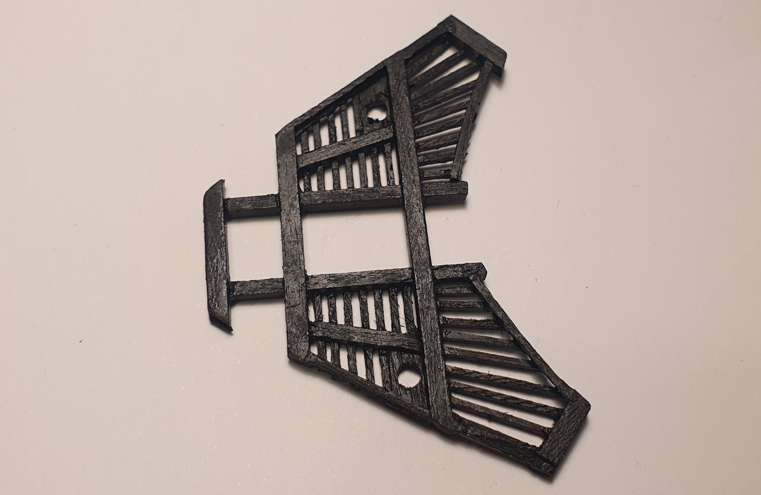
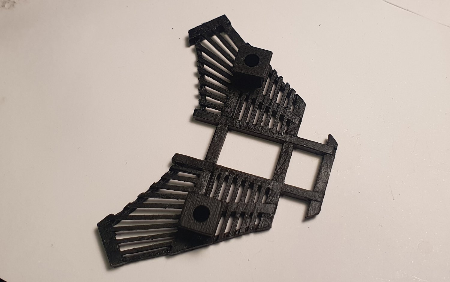
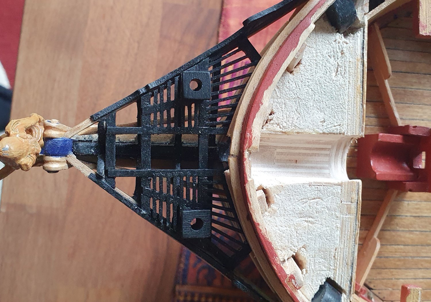
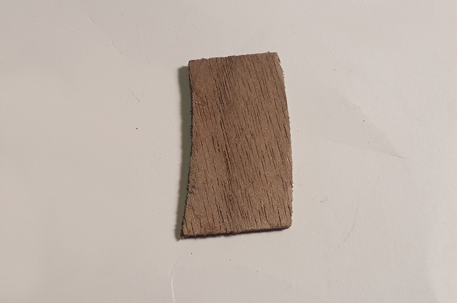
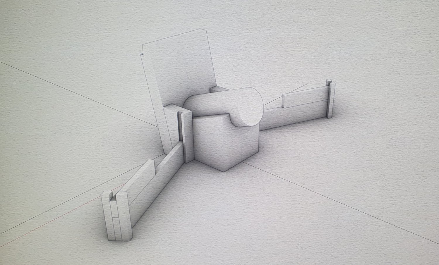
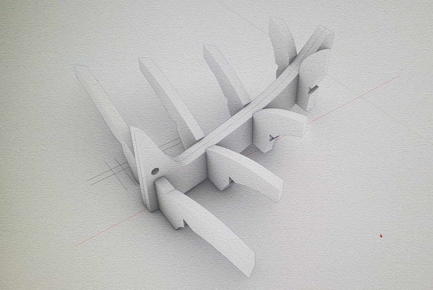
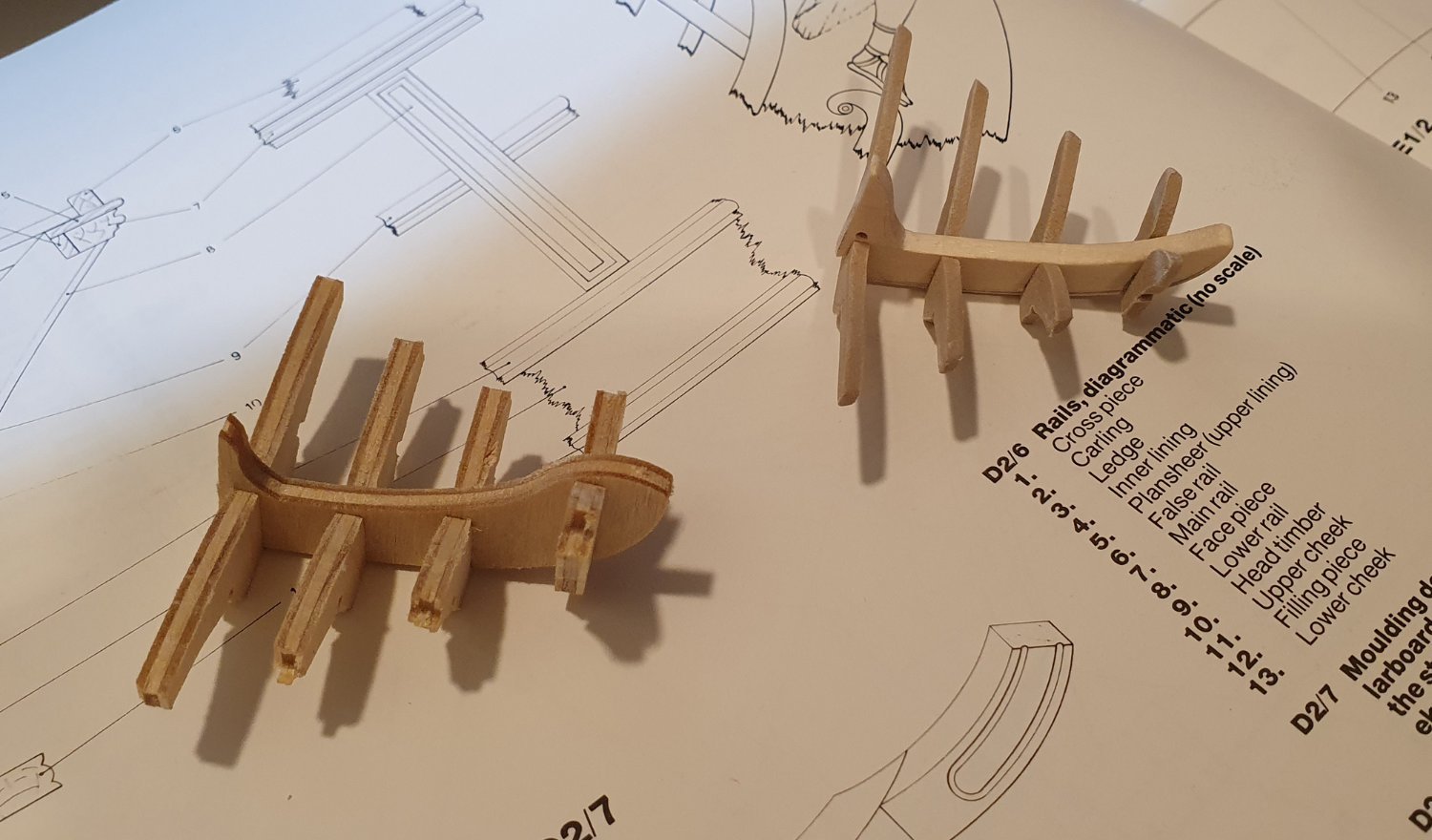
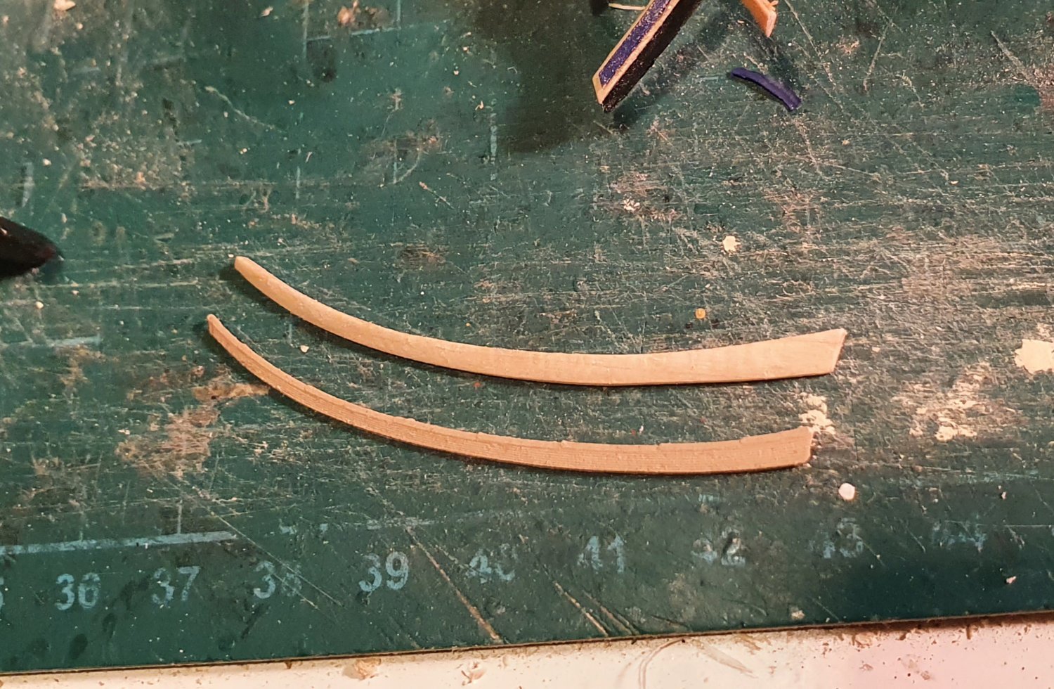
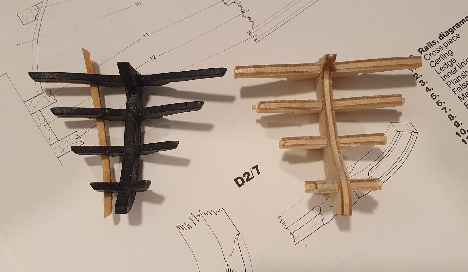
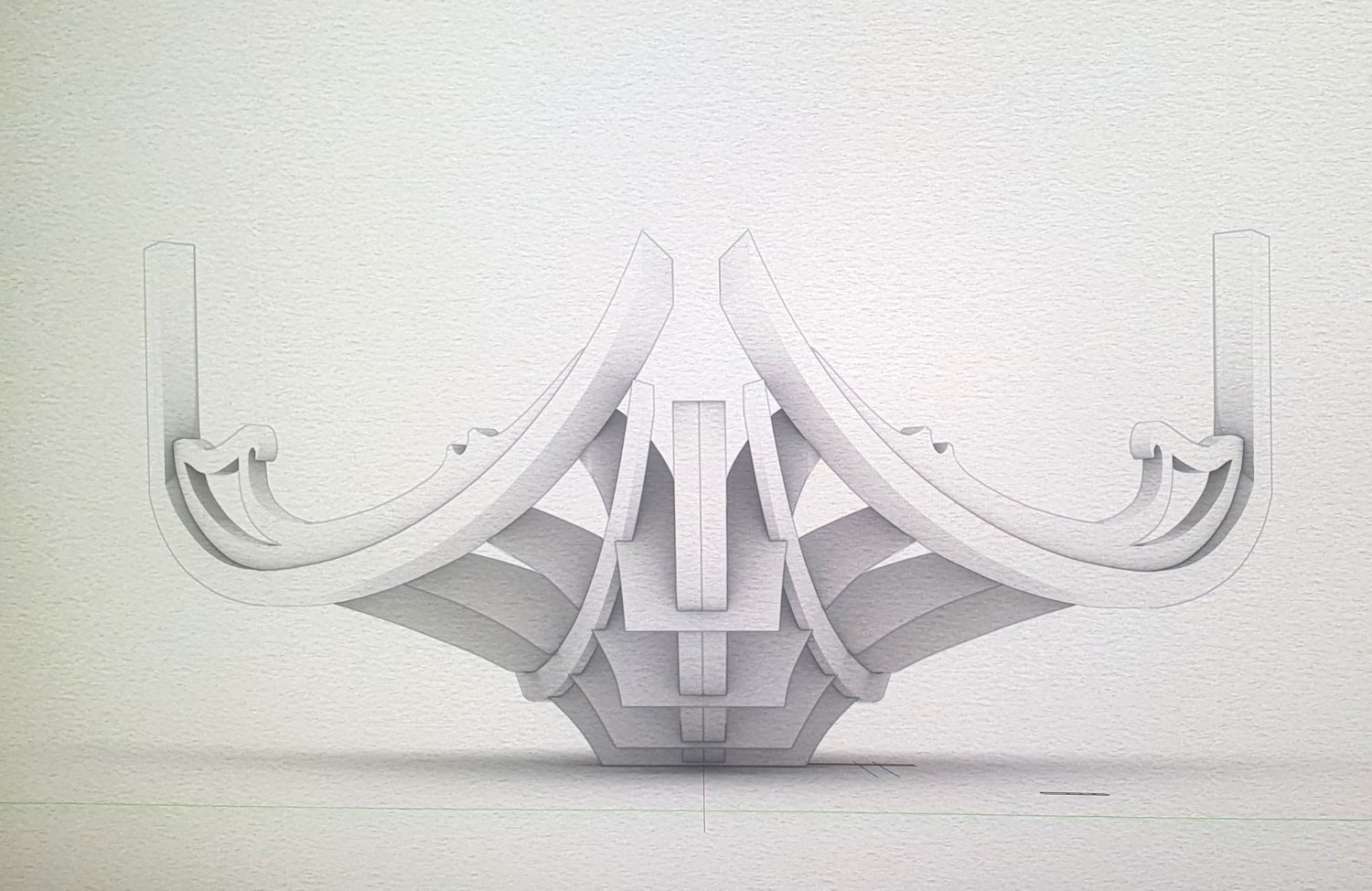
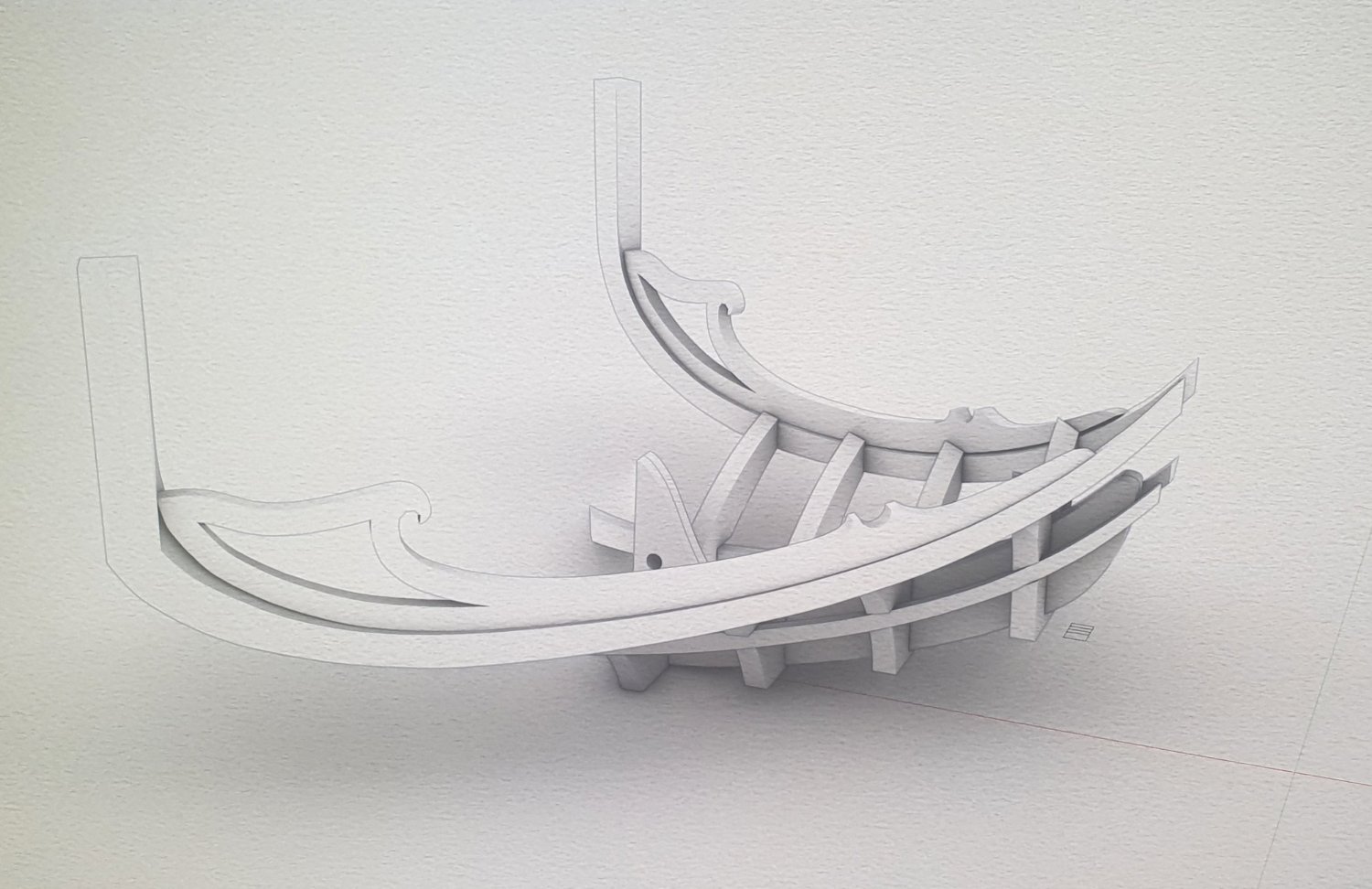
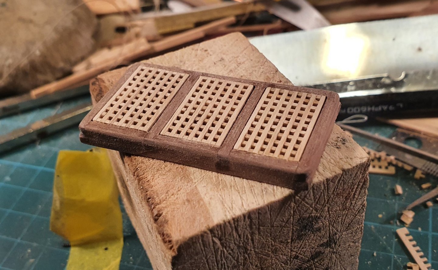
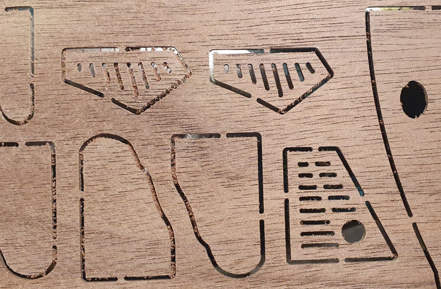
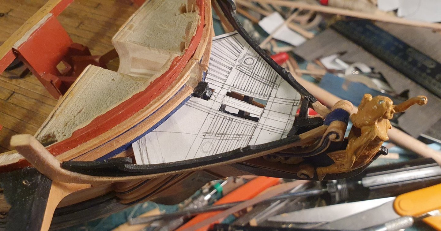
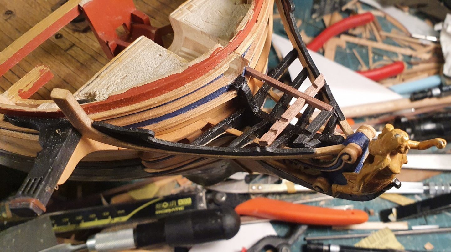
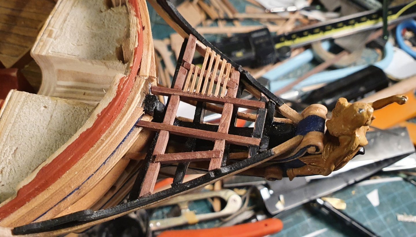
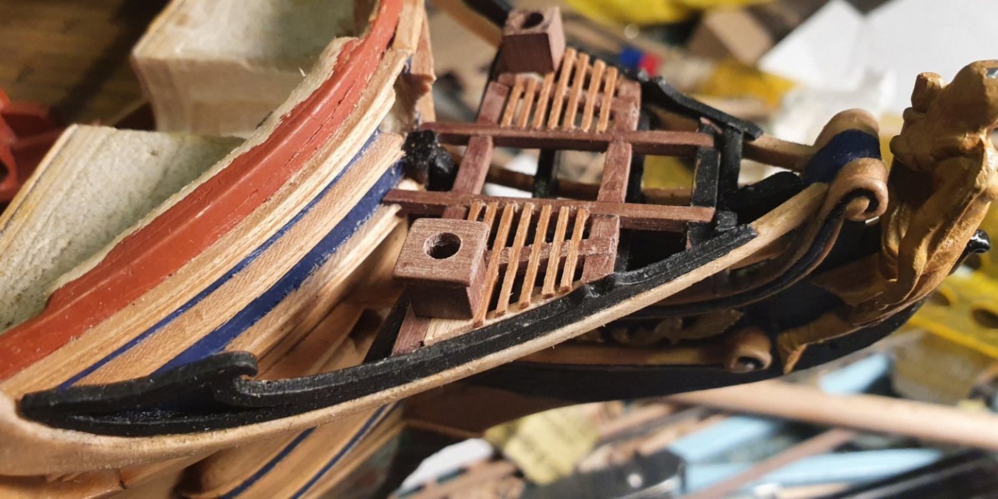
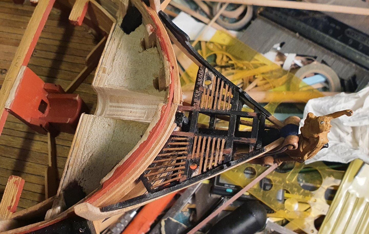
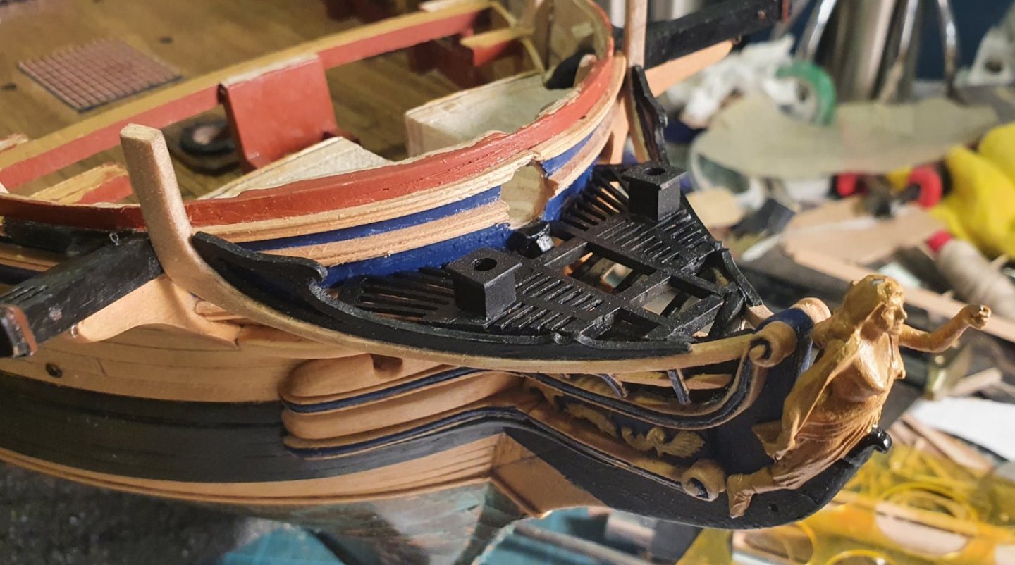
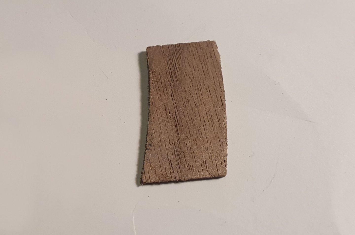
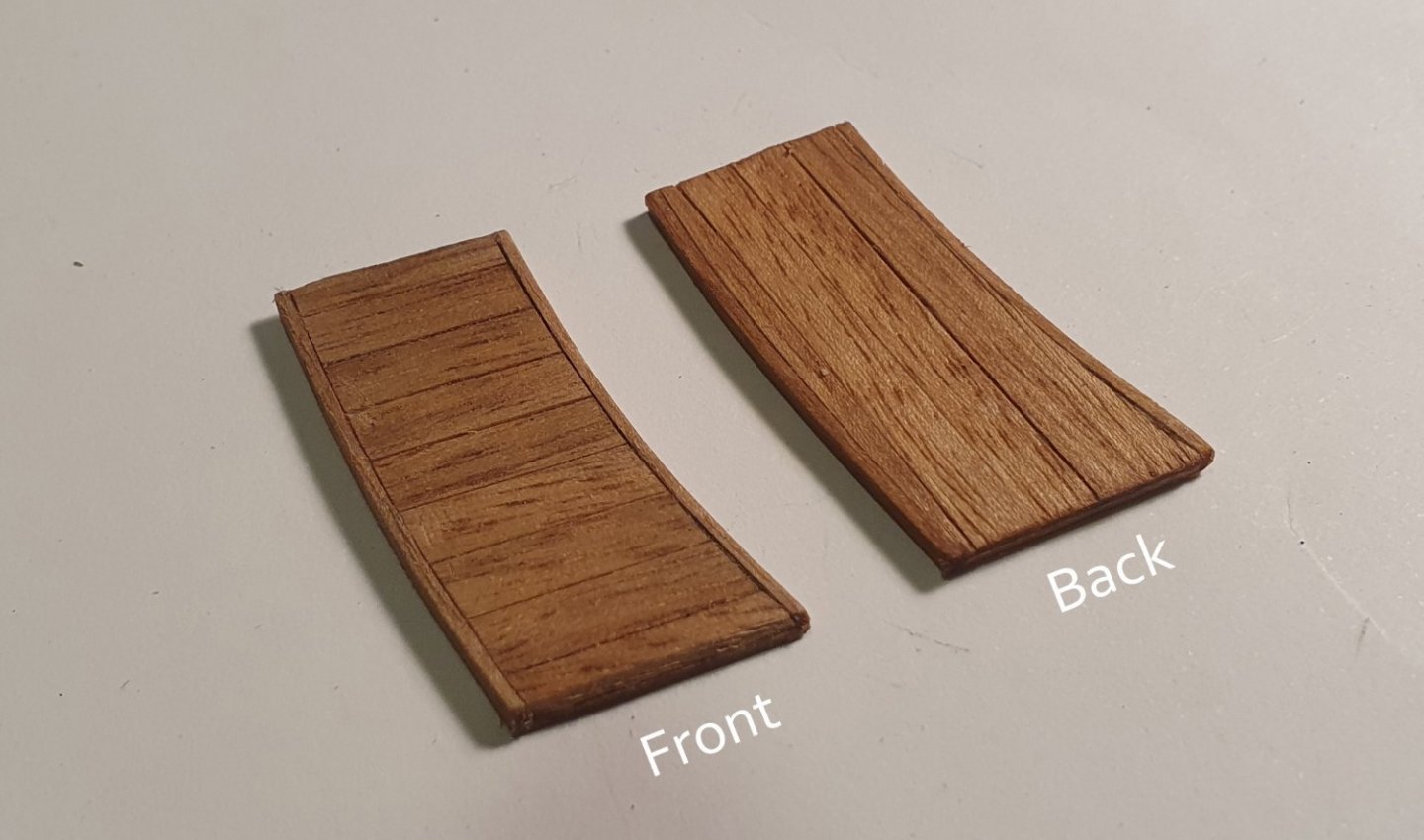
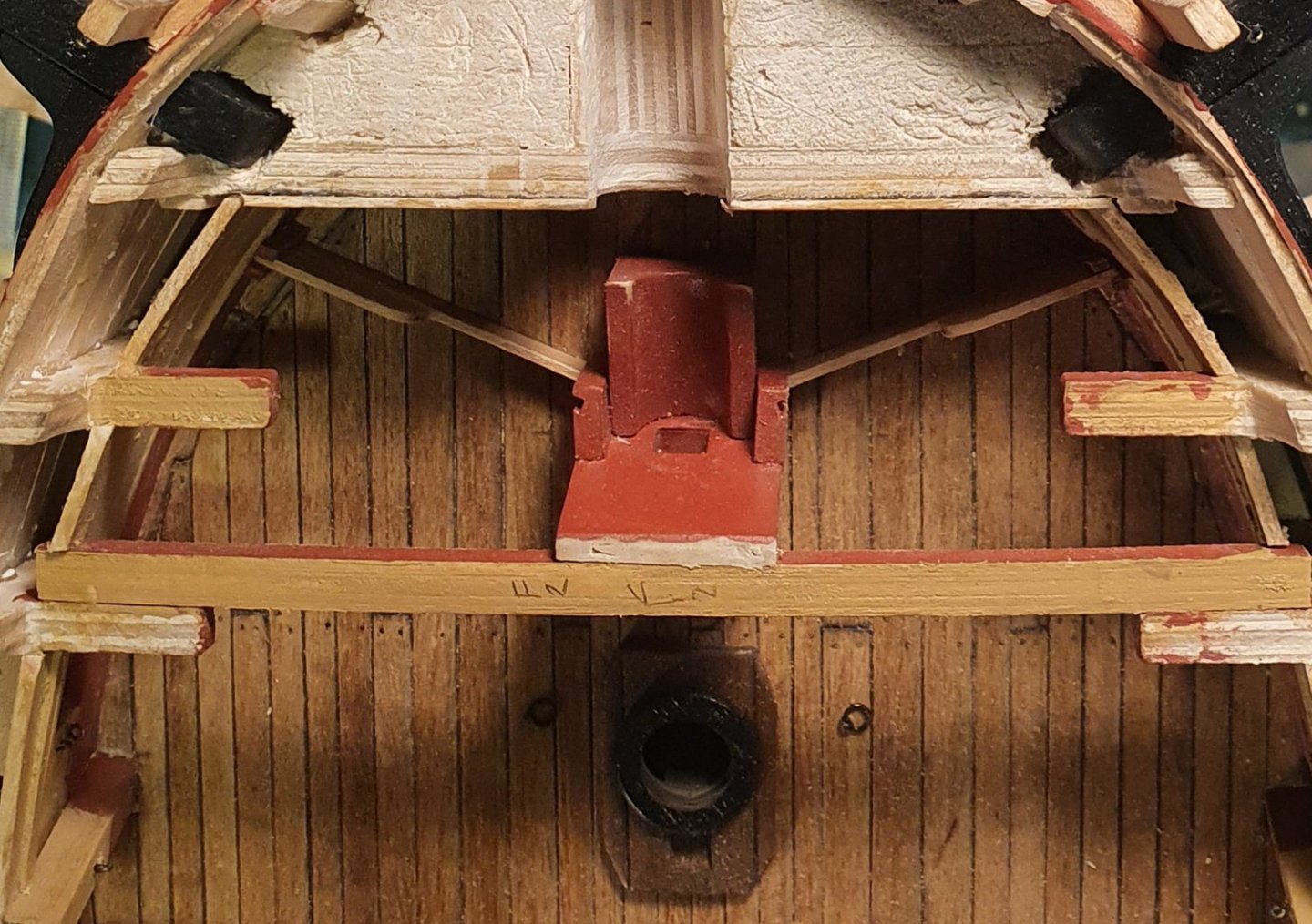
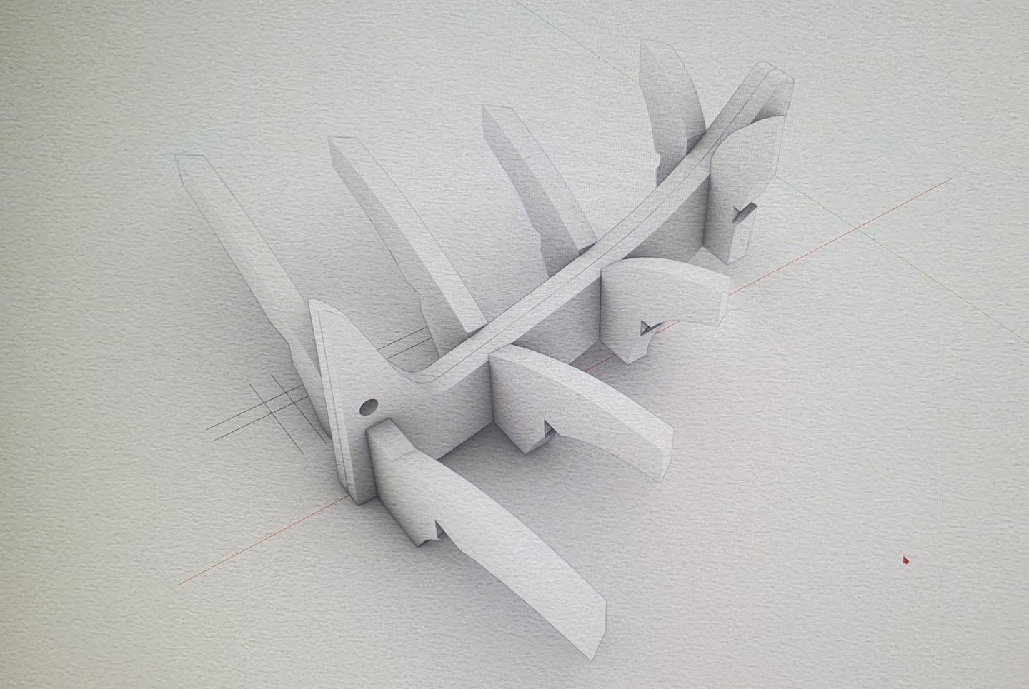
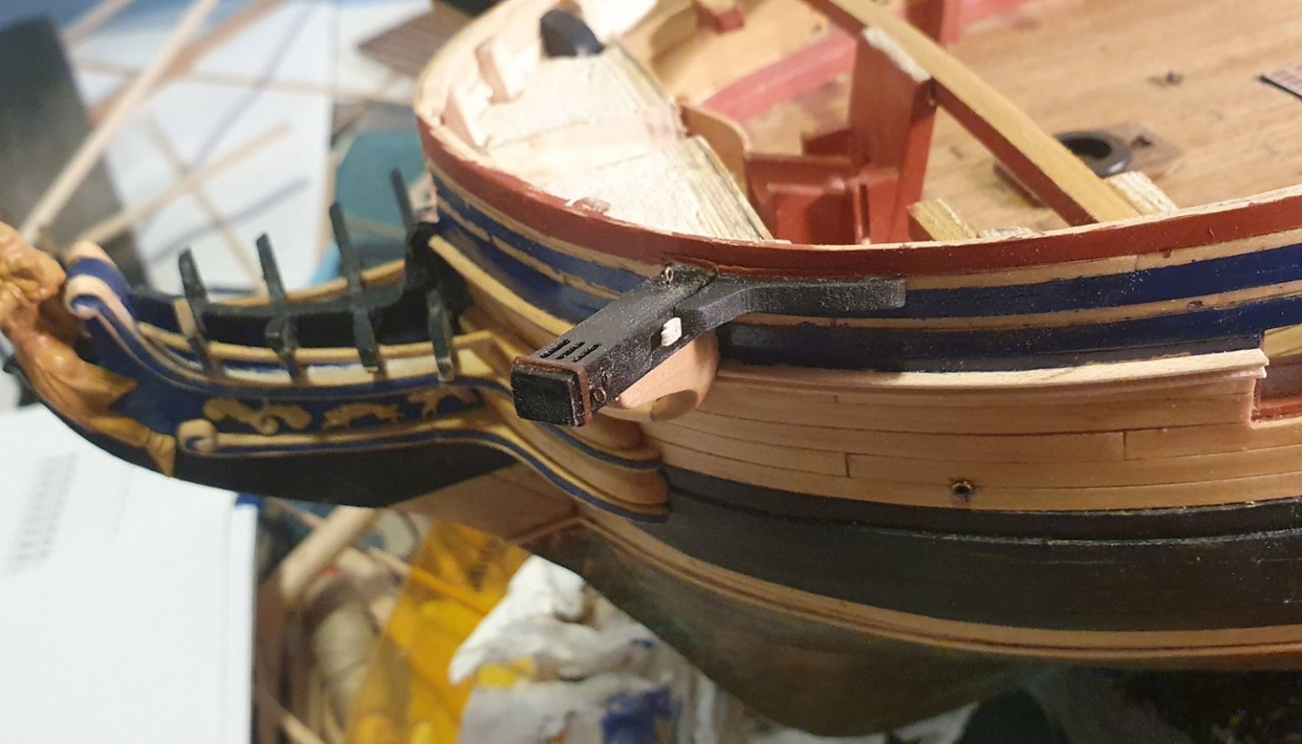
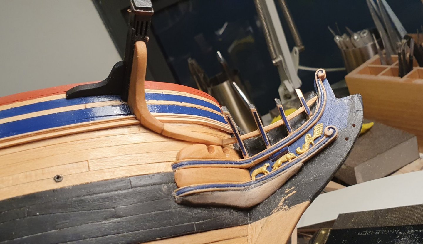
Before ploughing on with the cannons I decided to tackle the gratings at the bow. The kit parts look like they contain too much solid and not enough void while the AOTSD drawings indicate a very complicated structure with a lot of subtle curves and non orthogonal shaped beams. I felt that a simplified version of the AOTSD structure would be best. Expecting some dramatic asymmetry I used some heavy paper stock to cut out a template that fit the available space. I then drew the beam pattern onto this which allowed me to determine the exact dimensions for the main cross pieces. These were notched and joined together with the carlings and I then added the ledges. I started off building the seats of ease out of notched timber planks to form the case but I was struggling to keep these square and level. I decided to cut my losses and just drilled a hole through a length of square walnut section. Much simpler and neater looking. They were then finished off with a seat and painted black. The ledges next to the bow were quite tricky to place but once everything was glued together I was able to remove the whole section which facilitated painting and finishing. After that was completed it snapped back into place with a satisfying click. I did a last check to see if the long drop through the seats of ease avoided the rails below and then glued it in place. While I was in the neighbourhood of the bow I constructed the anchor lining. The kit piece is just one section of laser cut walnut. I was sceptical that they would make this out of a single piece of timber in real life so I used some artistic licence and laminated horizontal timber planks on top of verticals and finished with an edge strip. These were then installed on the anchor lining bolster. I Just have to fix the top joint. Subsequent to building this I saw a contemporary model with a similar arrangement of horizontal planks.


-
Thanks but it is a bit of an illusion. I started the build in January 2021. The rapid posts are just me catching up because I started by build log so late. I am getting close to the current state of my build though. Once that happens the progress reports will slow to a trickle. Regards, David
-
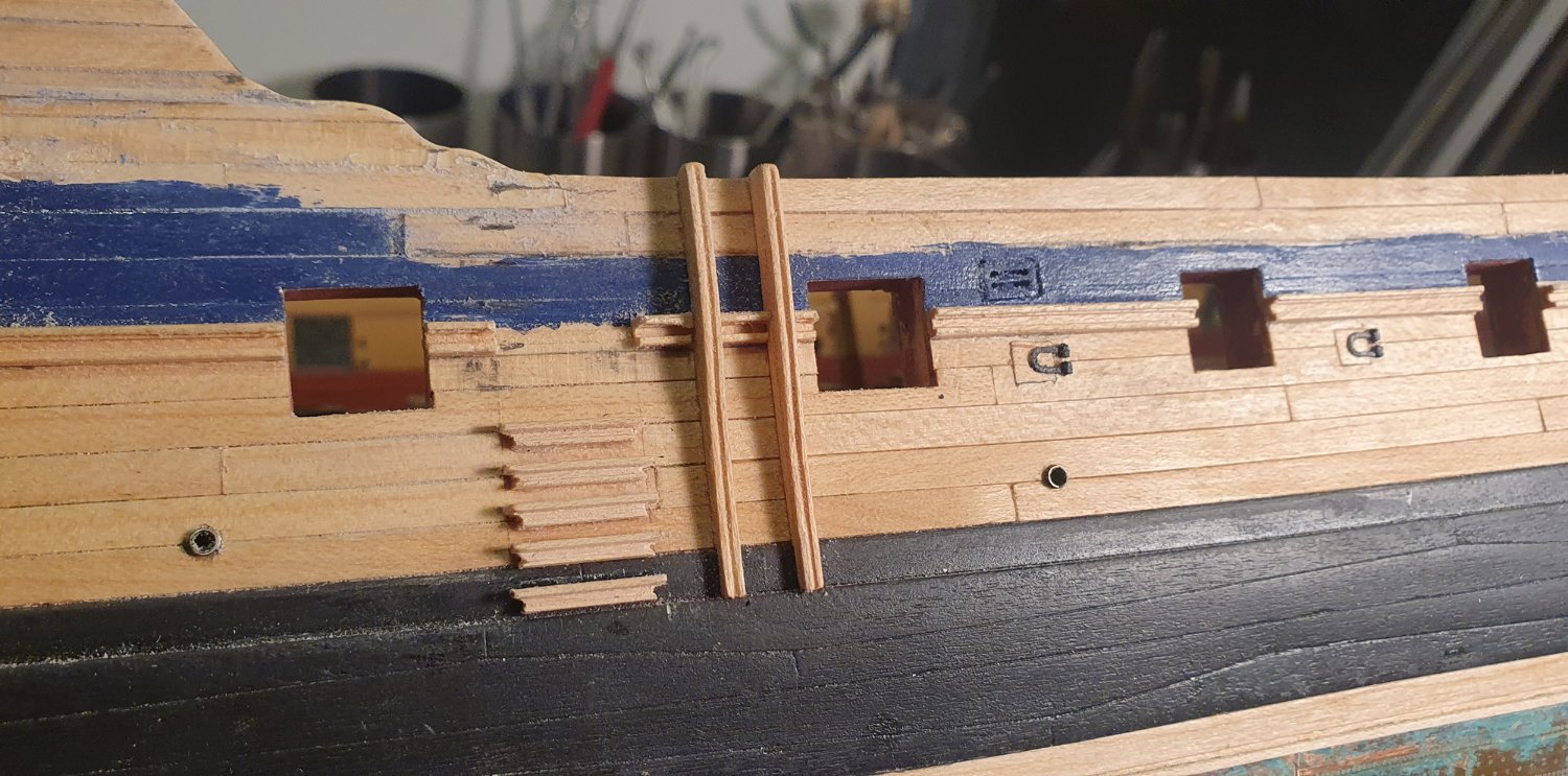
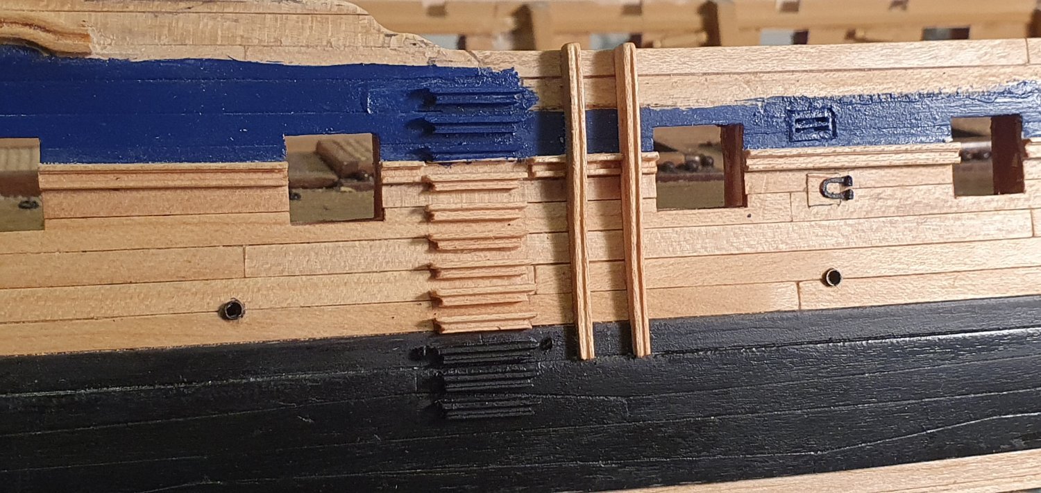
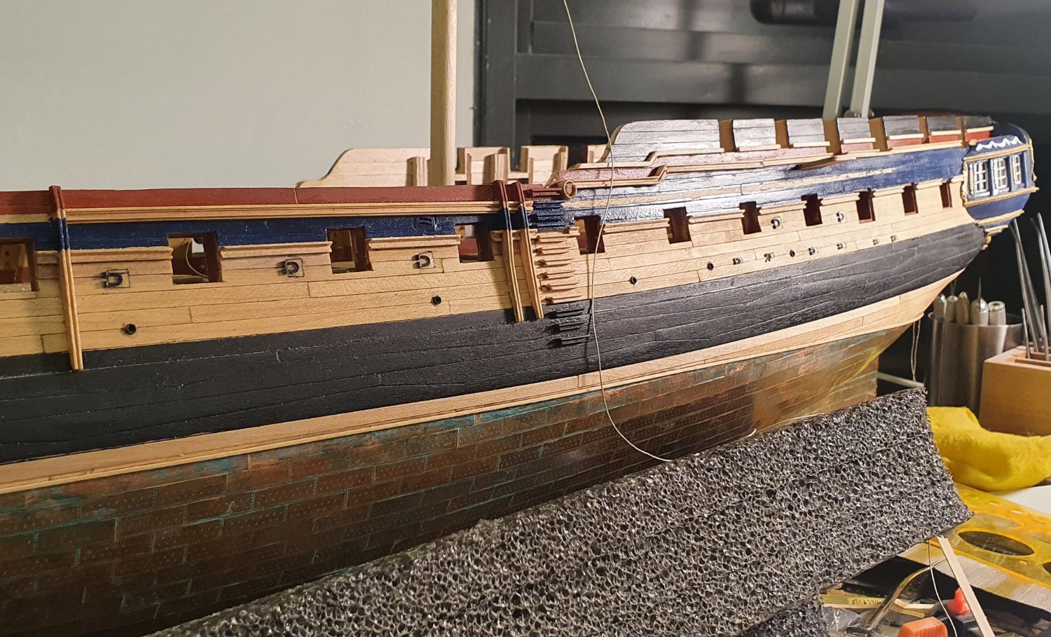
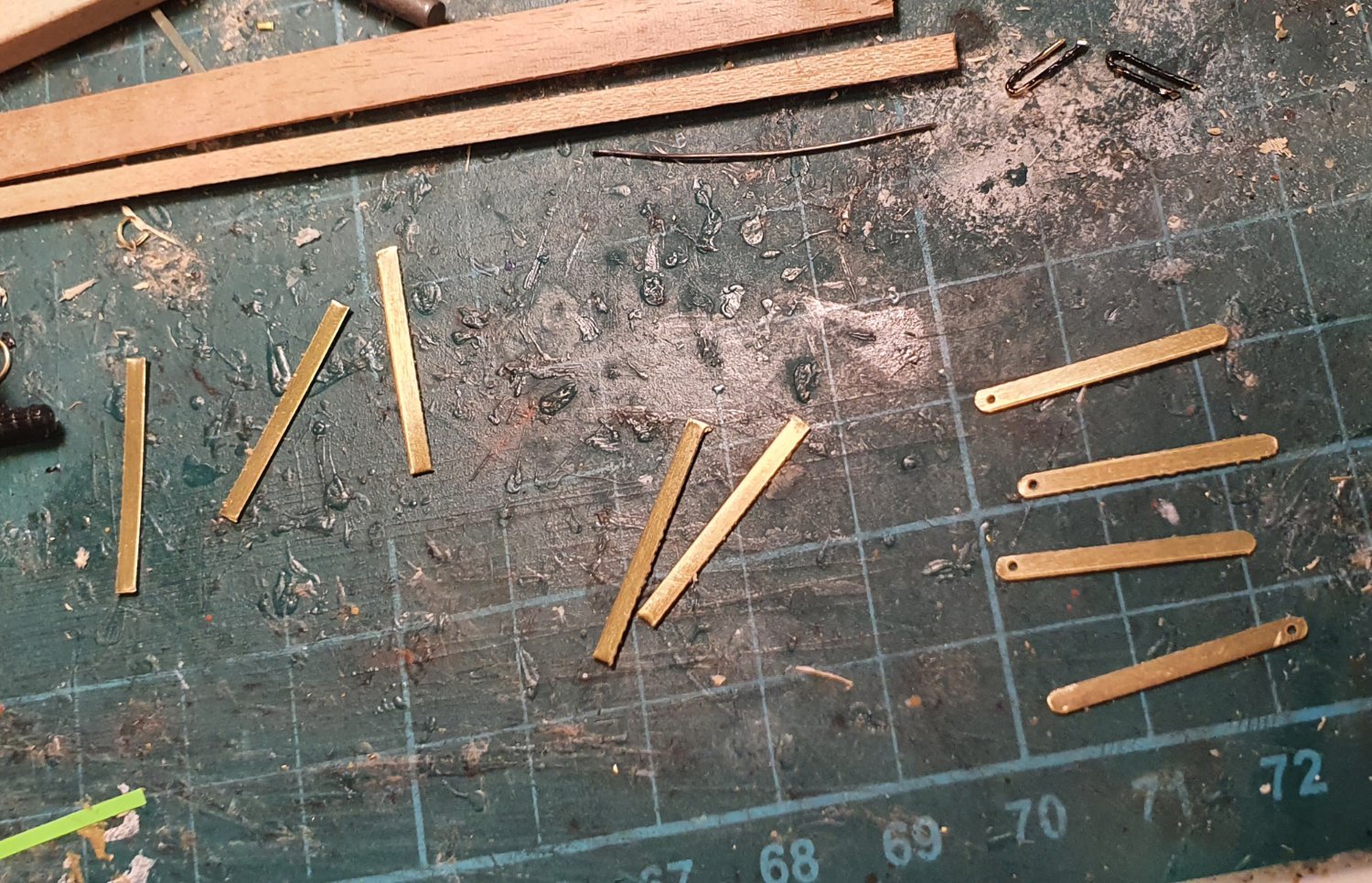
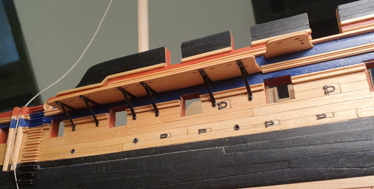
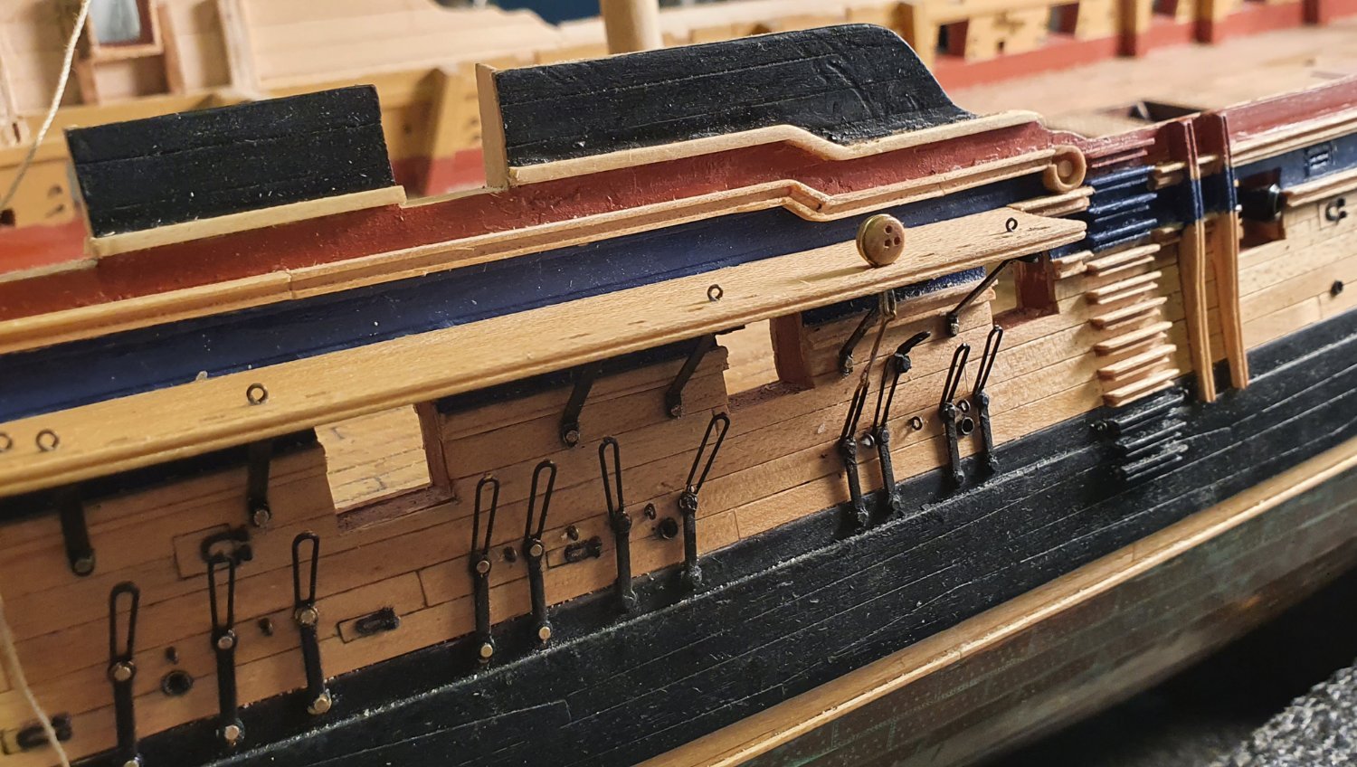
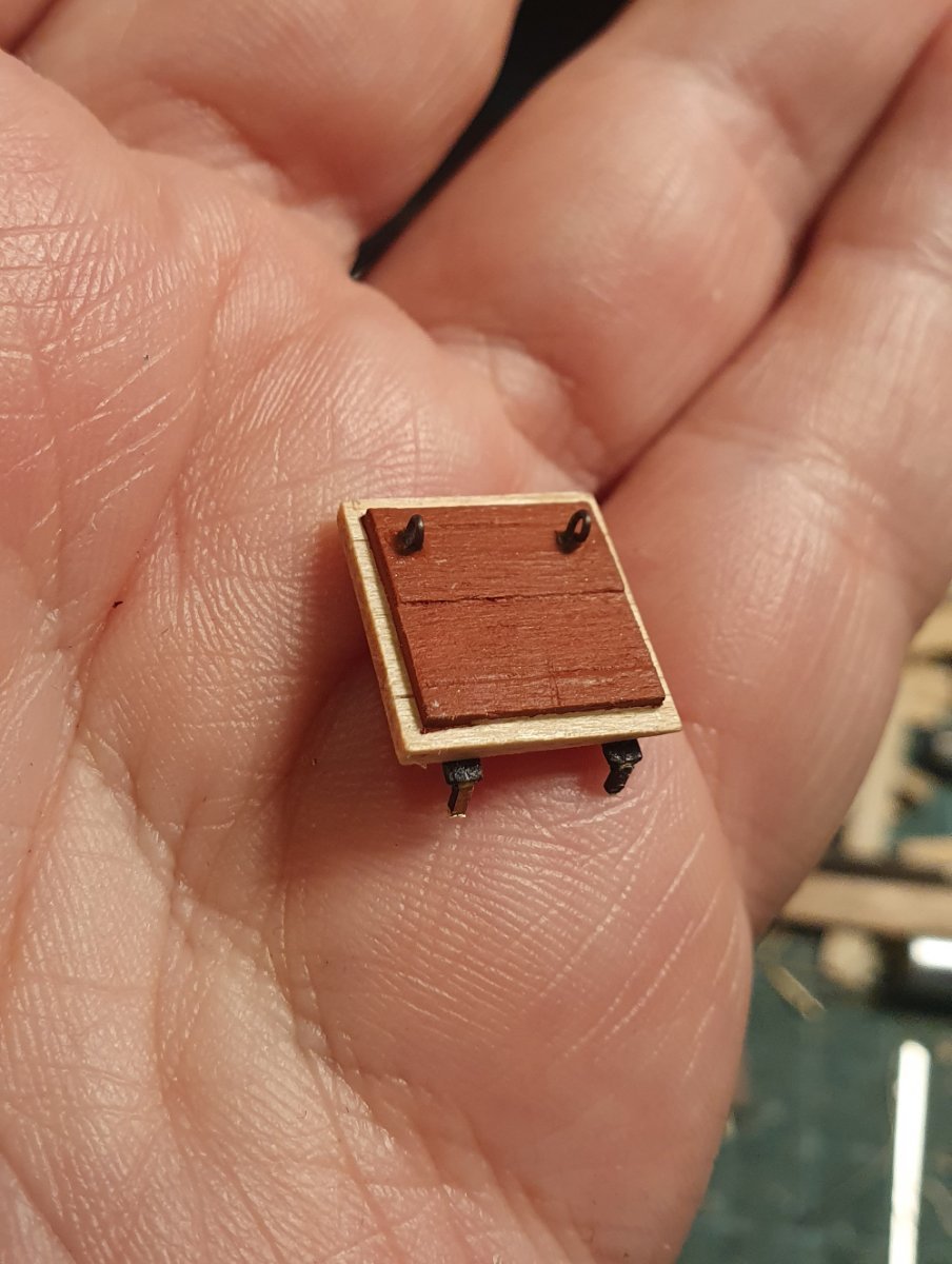
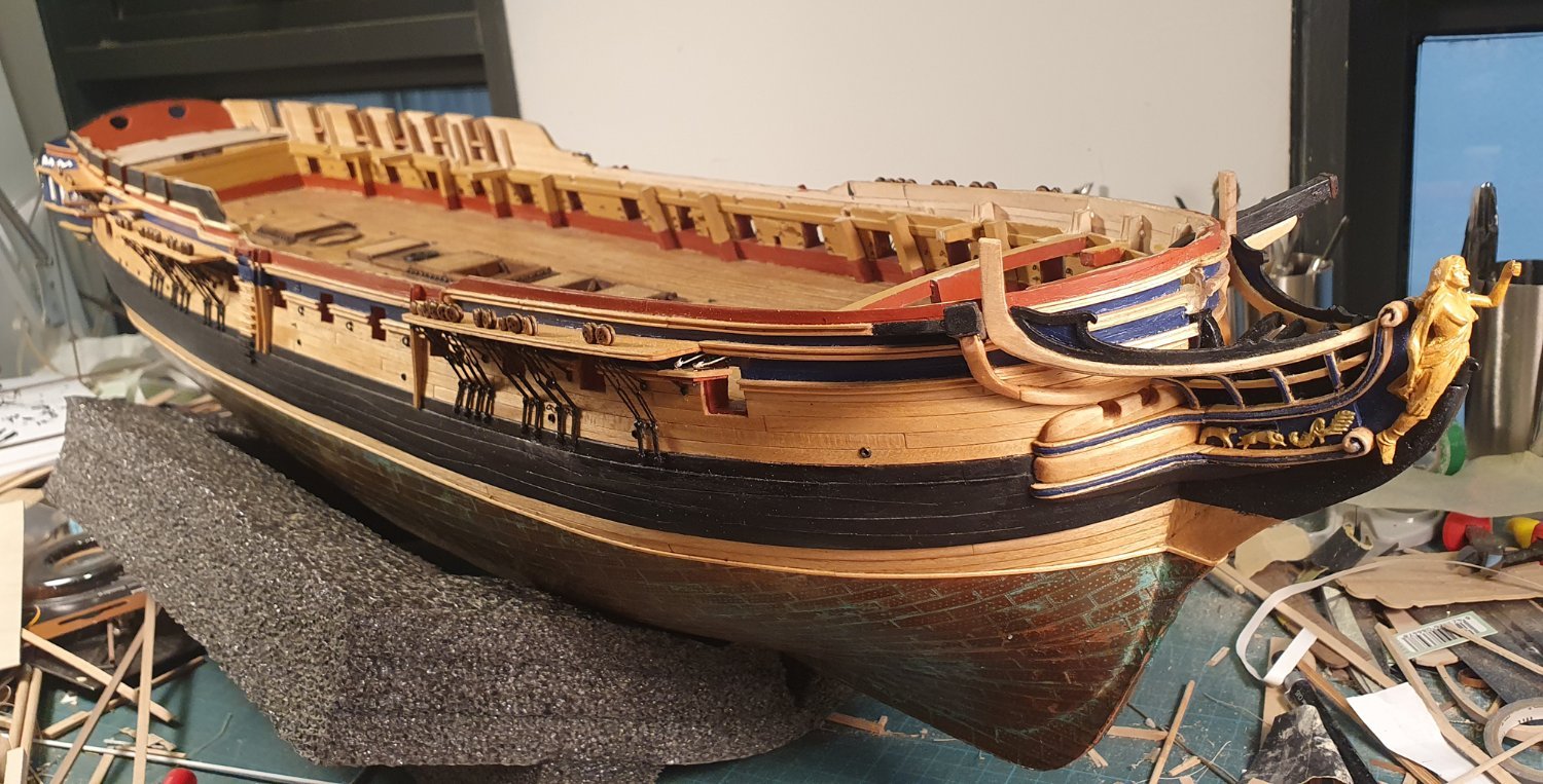
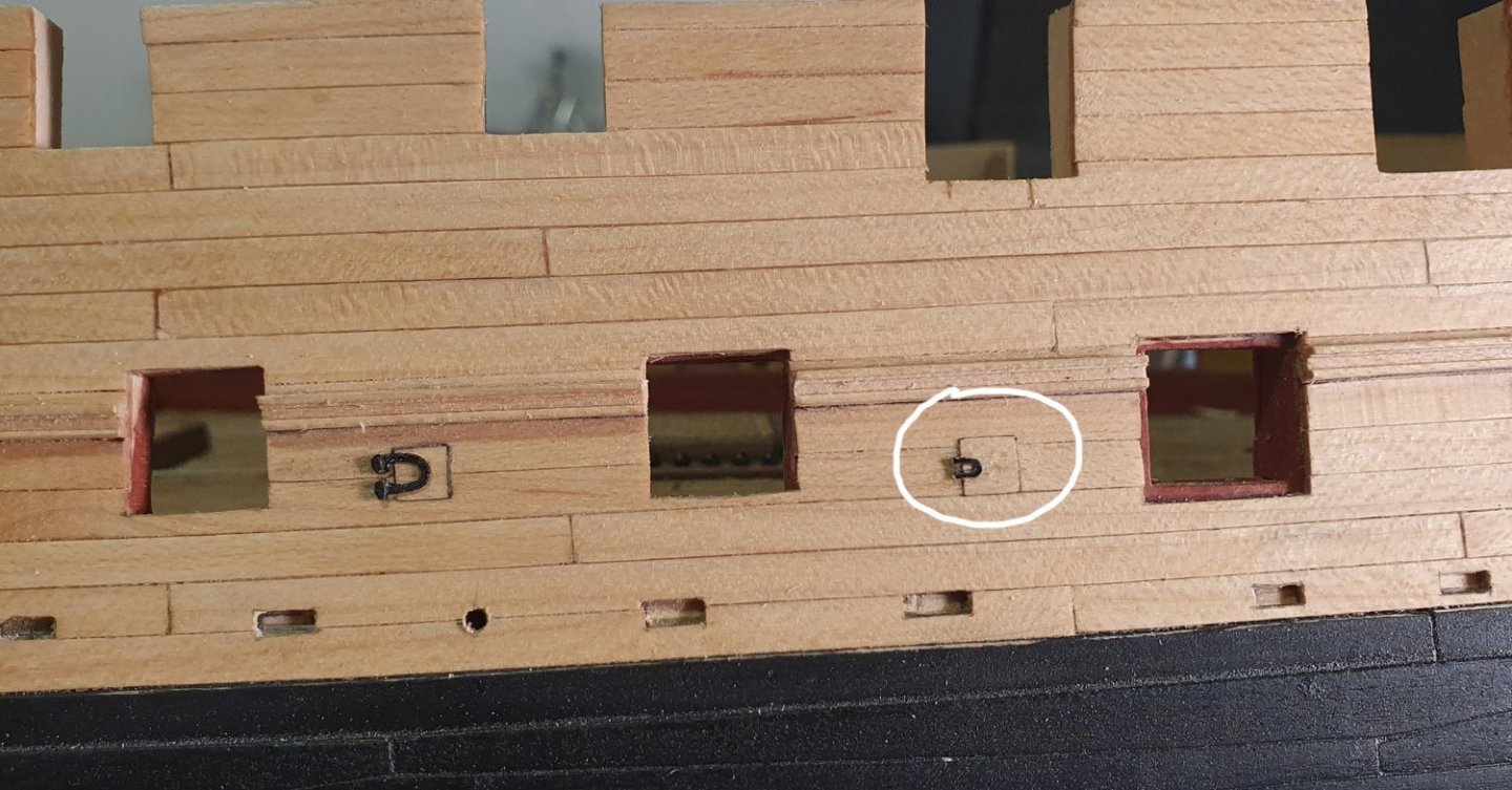
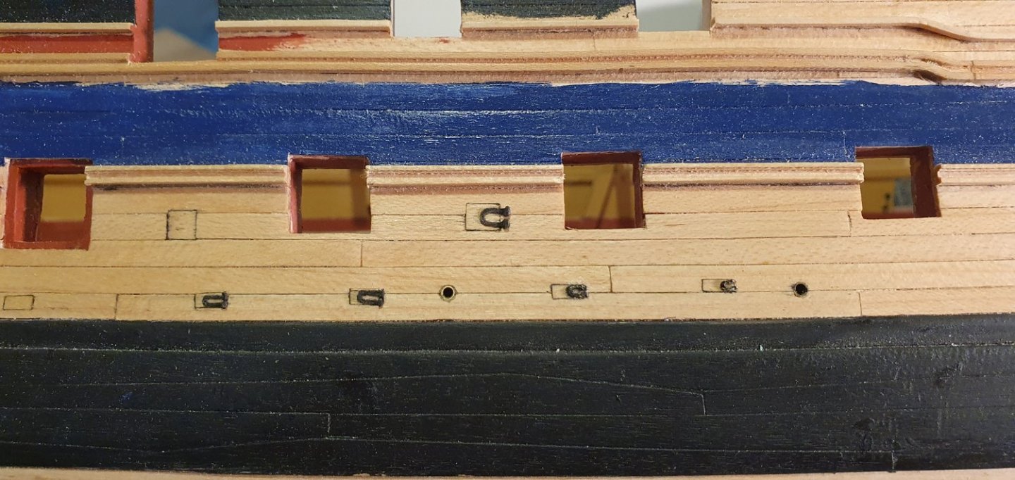
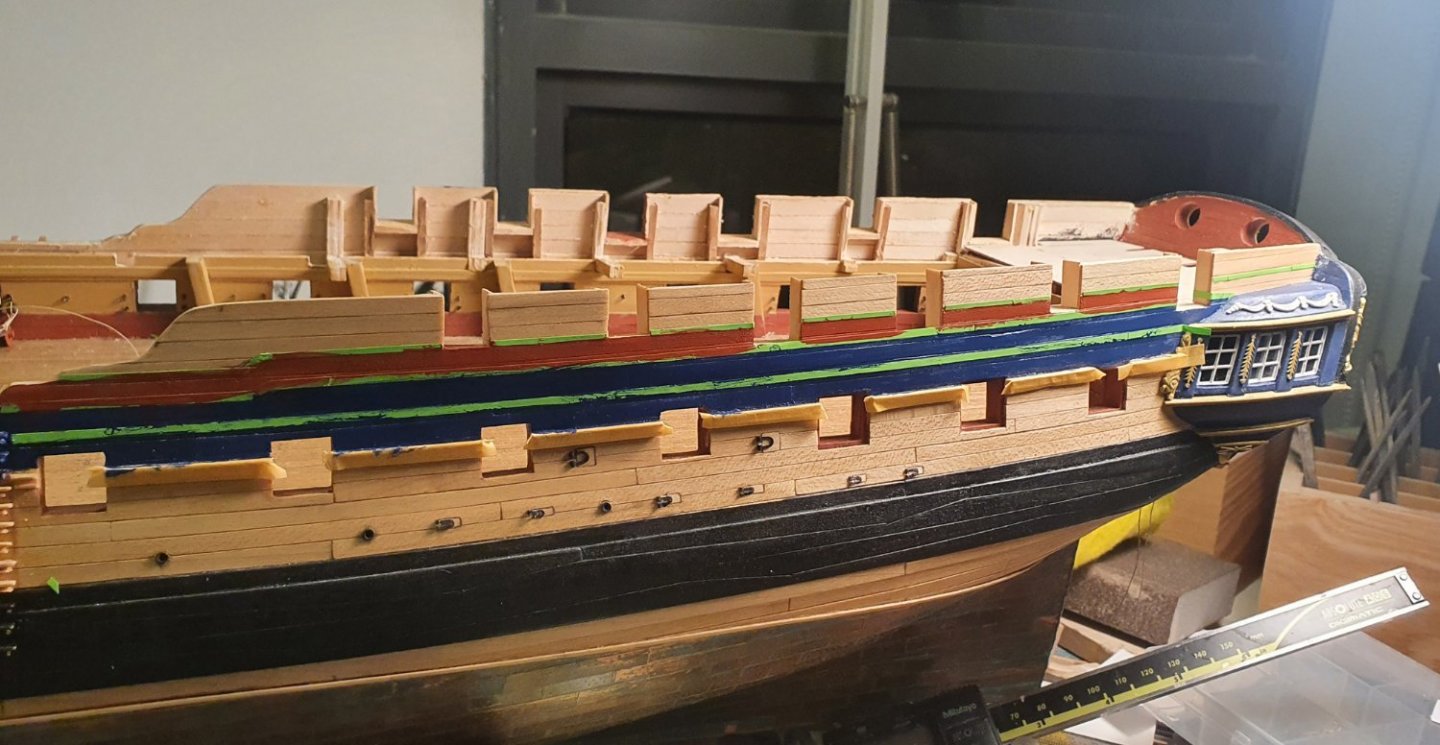
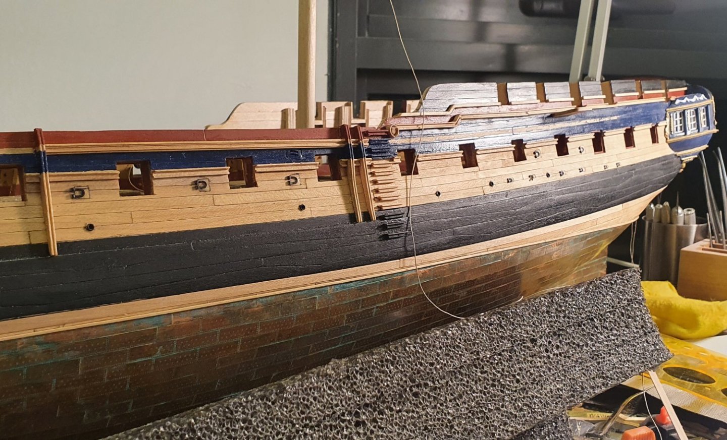
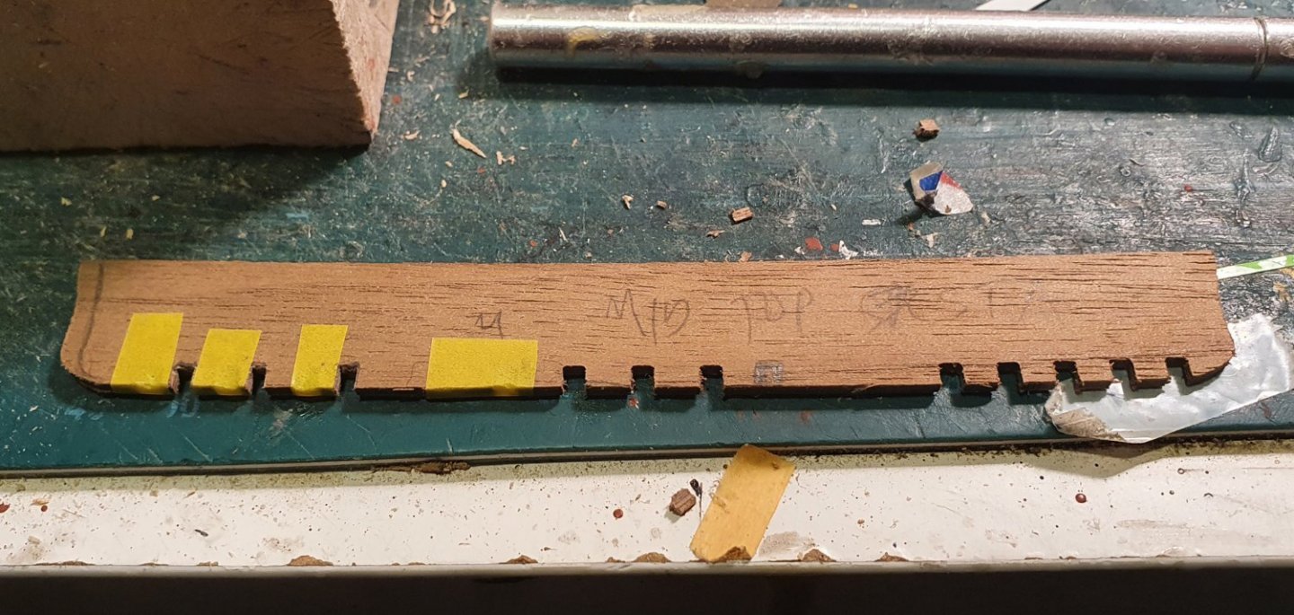
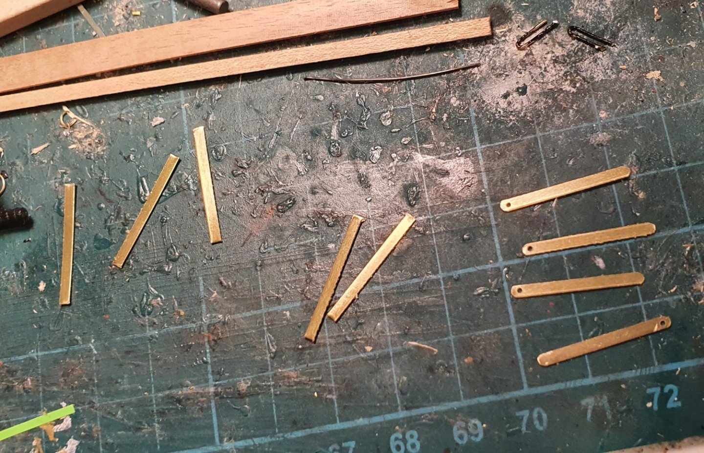
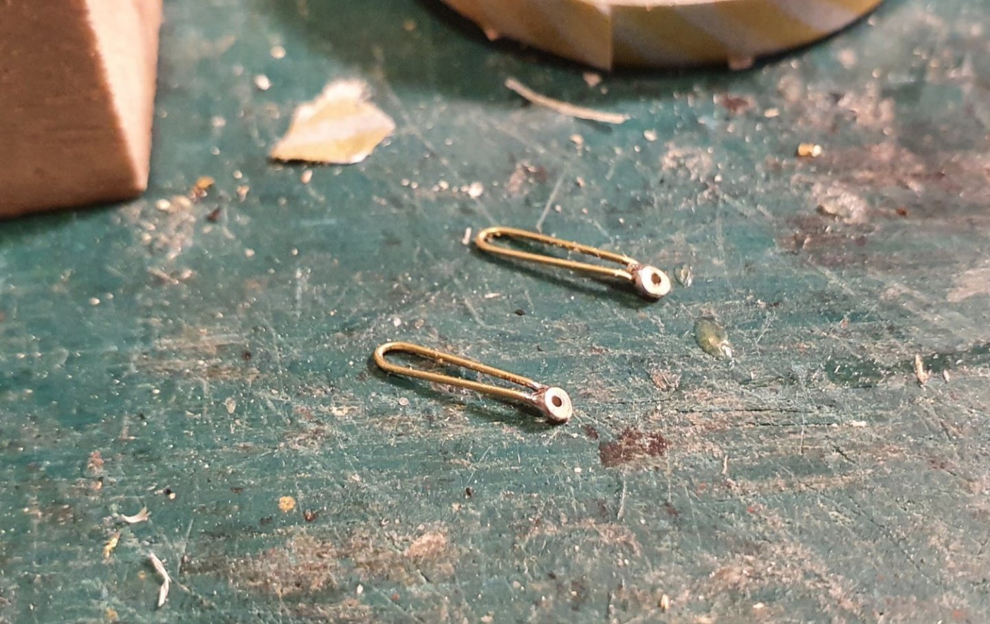
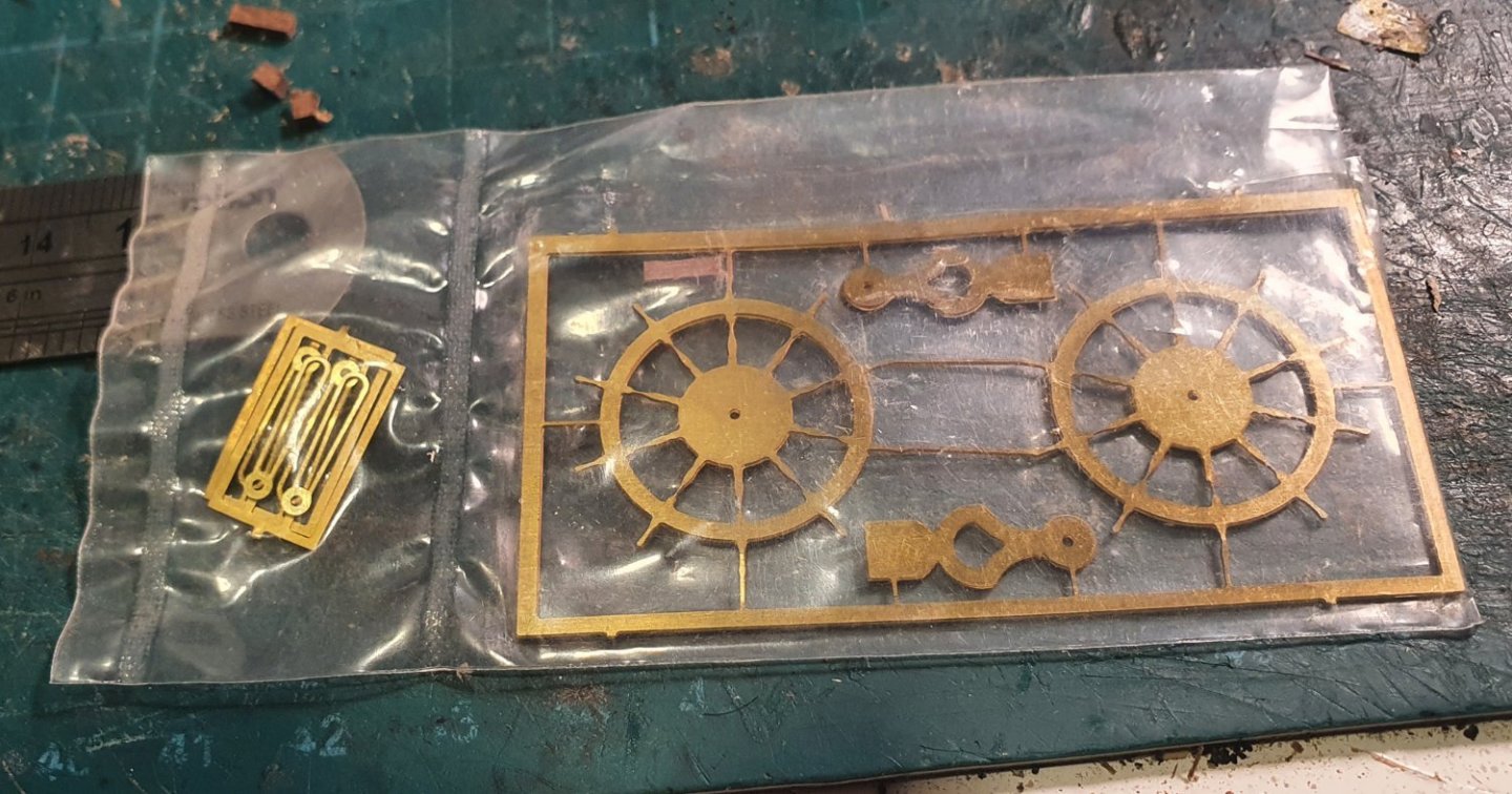
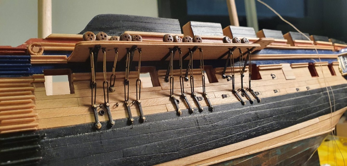
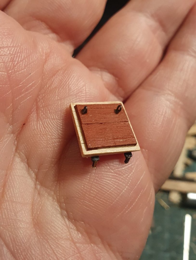
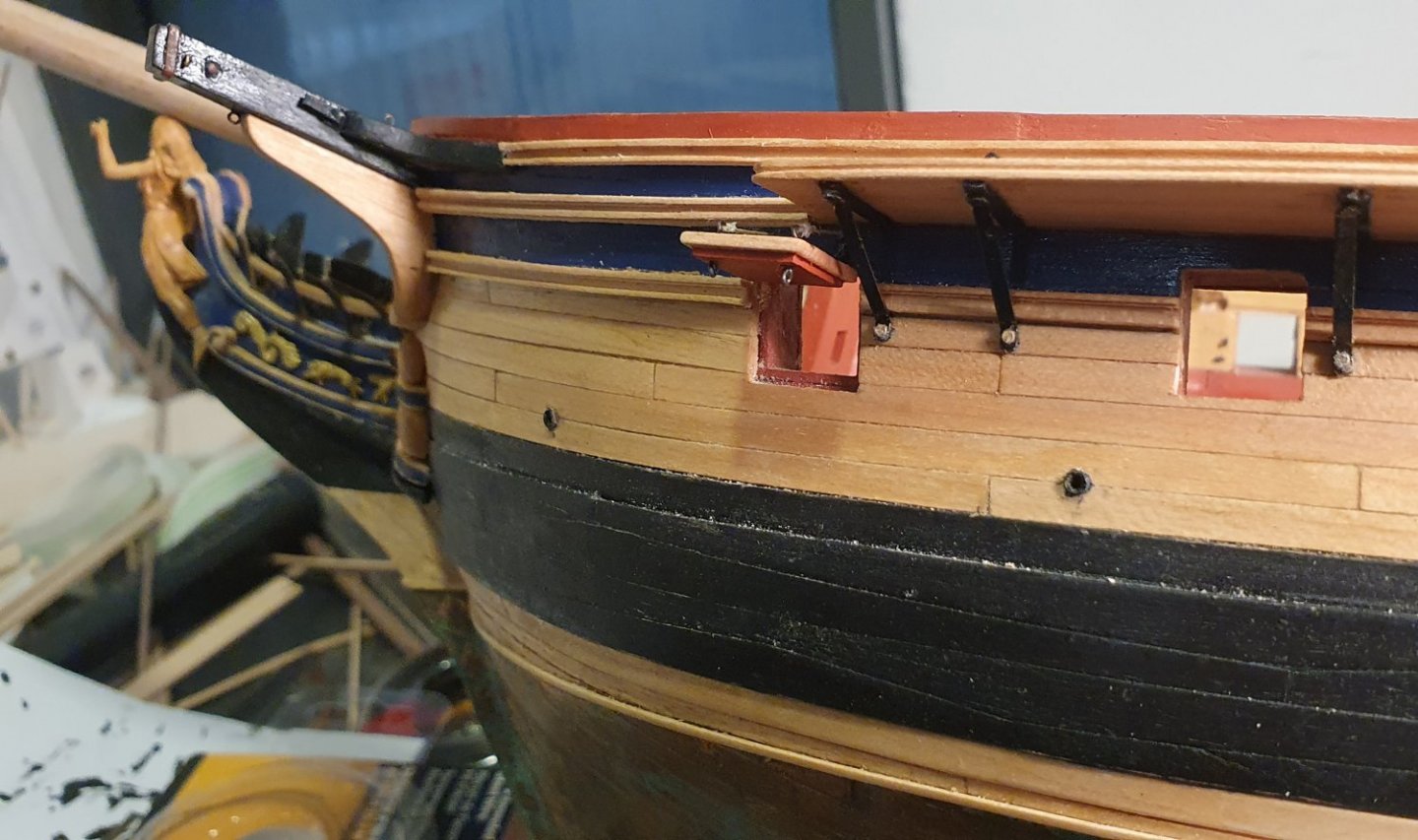
I thought that I should finish adding all of the features onto the exterior of the hull before I installed the cannons to prevent the possibility of knocking them out of position. I fitted the doors for the oar ports and ventilation scuttles. The photoetch hinges supplied with the kit were the wrong scale so I had to make new ones on the 3D printer but these pieces were right at the limit of what can be printed and lack definition. I added the fenders and sea steps which were milled out of maple. I marked out the position of the various rails and quarterdeck plansheer. I painted the various coloured stripes on the side of the hull before installing the rails. The rails were milled out of maple. I used maple to replace the cast pieces that were included in the kit as I was not keen on the profile and I also wanted these to be exposed wood. Next up I tackled the channels. Again I was looking to expose the wood finish so I had to swap out the kit supplied walnut for maple. The channels had to be rebuilt anyway as I had fiddled with the location of the gunports which meant the supplied pieces could not be salvaged. I used some dowels to create dummy masts which allowed me to run a line to approximate the position of the shrouds. I then located the position of the deadeyes on the channels so that they didn't clash with the location of the gunports. I noticed that the standard practice is to notch the channels to accommodate the deadeye strops. I decided that it would be easier to mill a slot in the channels rather than fumble about with cover strips. I gave the edge of the channels a simple profile using a scraper. The channels were fixed into the hull by pins drilled into the vertical surface. The number of kit supplied knees that are used to support the channels was insufficient. I needed six for each of the main and fore channels and three for the mizzen channels which meant I had to have a total of thirty. I ended up remaking all of these for consistency. I used some brass strip which I cut to length then rounded and bent the ends. I drilled a hole to allow for a nail to fasten them to the hull. I affixed a strip of styrene painted black to the underside of the channel to approximate a tee plate. Like some of the other Artois class builders on this site I had a problem trying to use deadeye strops provided with the kit. The opening is located at the bottom of the strop and the strop itself has been blackened which meant that it was very hard to achieve an adequate solder joint. This weak joint would be at risk of failing once you put any tension on the middle links. For the 5mm deadeyes I ended up using some 0.58mm diameter black annealed wire which I bent around a nail to form a loop and then worked around the deadeye. I cleaned this up with a file at the joint so that it could be soldered. For the 3mm deadeyes I found some photoetch blackened strops from HiS Models that were a lot easier and faster to use. I located and fixed the preventer links and toe links. There are not the correct number of toe links included in the kit so I had to construct four additional ones using 0.5mm diameter brass wire and some brass strip. A few weeks later I discovered that they had included an additional four of these in a separate bag attached to the photoetch for the ships wheel. I foolishly followed the kit plans and added 4 deadeyes to the fore channel despite being aware that there are only 3 shown on the AOTSD drawings, the NMM documentation and the contemporary models. It was not a good idea but I am not going to dwell on it now and will decide how to deal with it at a later date. I formed the middle links from 0.5mm brass rod. I measured the distance from the strop to the toe link and pre-bent them around two nails set apart at the same distance before fixing them in place. I tried soldering these to form a closed loop but that proved too difficult as access to the back of the link was limited and the solder was ending up everywhere. I fashioned the gunport lids out of some maple strip. I milled a recess around the edge to form a lip then added the photoetch hinges and eyebolts fashioned from 0.41mm diameter black annealed wire wrapped around a 0.5mm rod. I added various eyebolts and sheaves but I suspect there are a few missing bits and pieces to still add however the hull has progressed far enough that it now resembles a ship and means that I have no option but to start on the dreaded cannons.


-
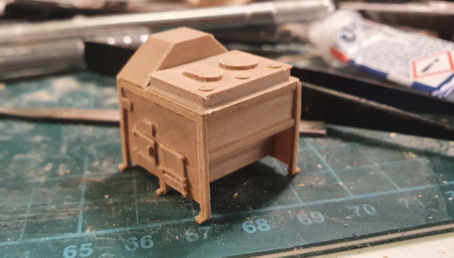
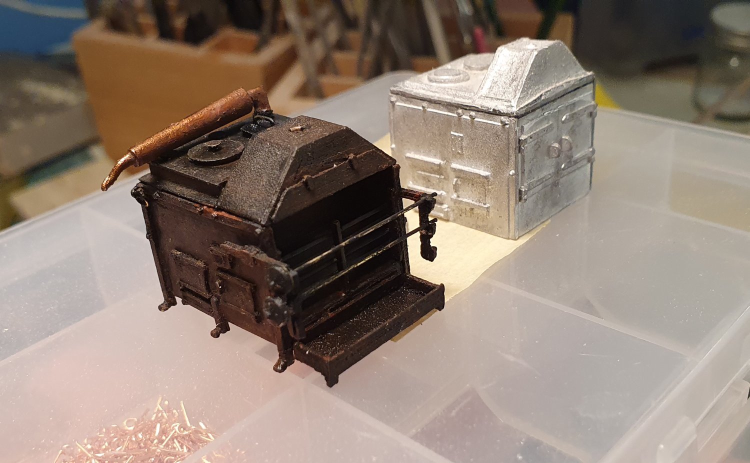
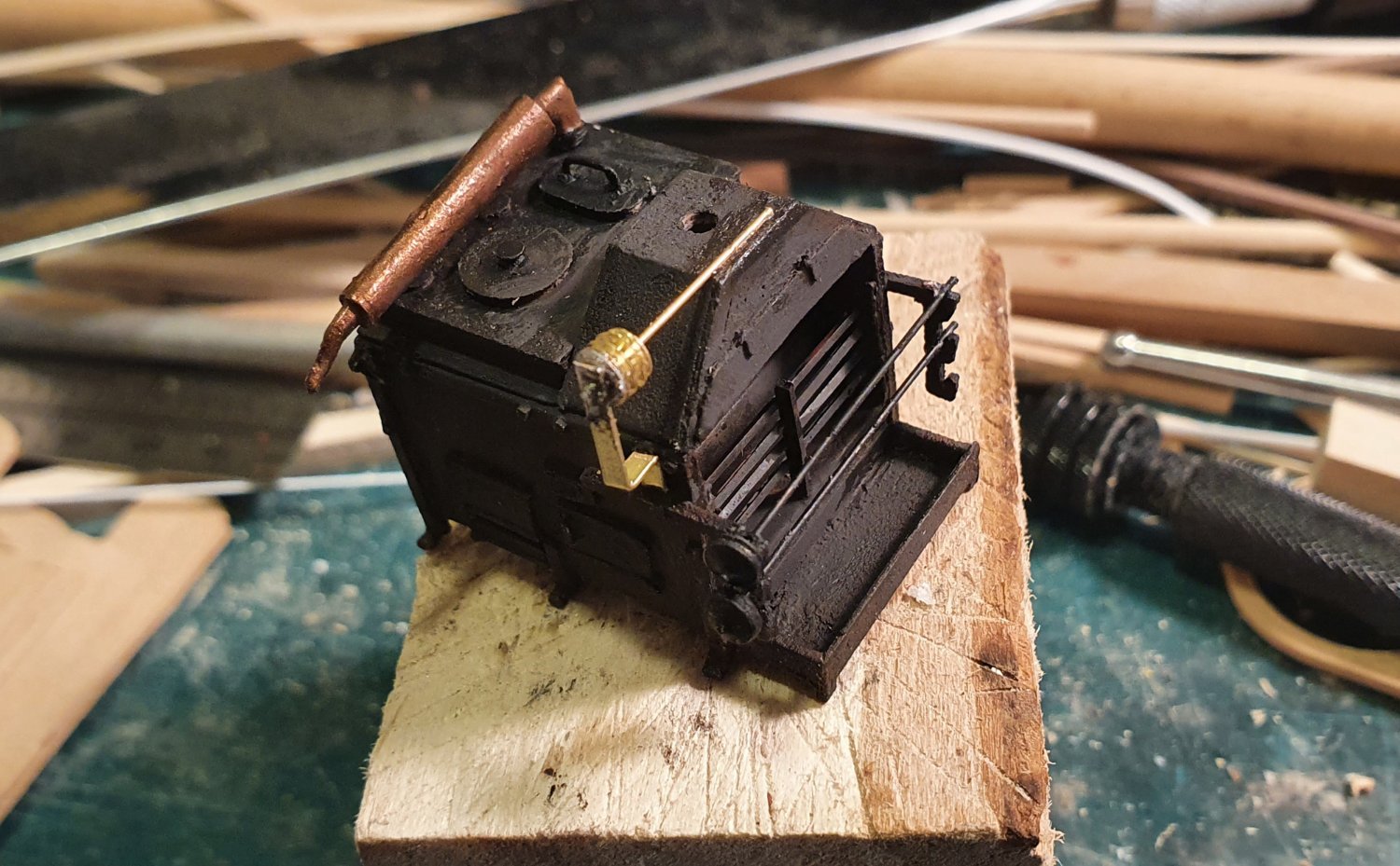
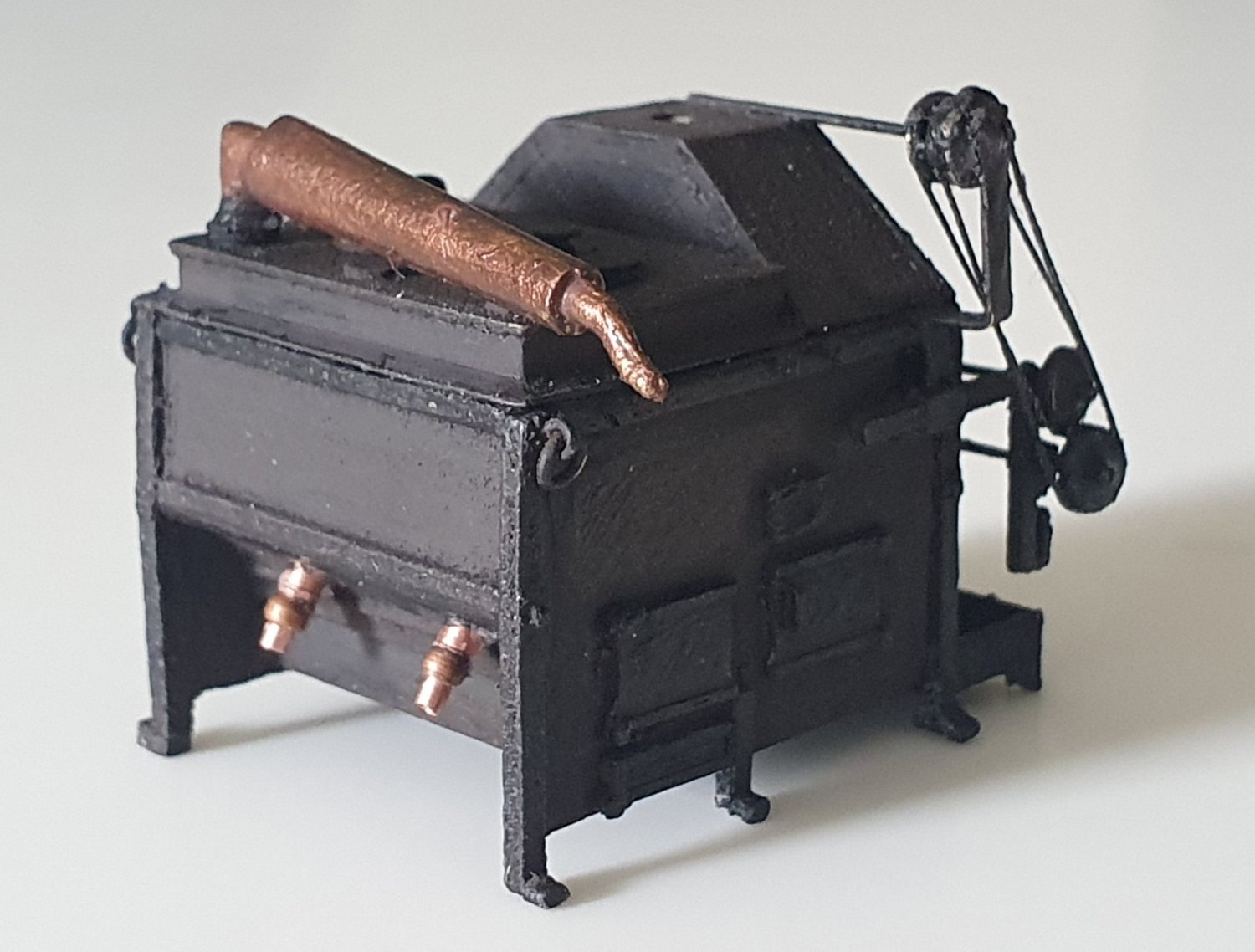
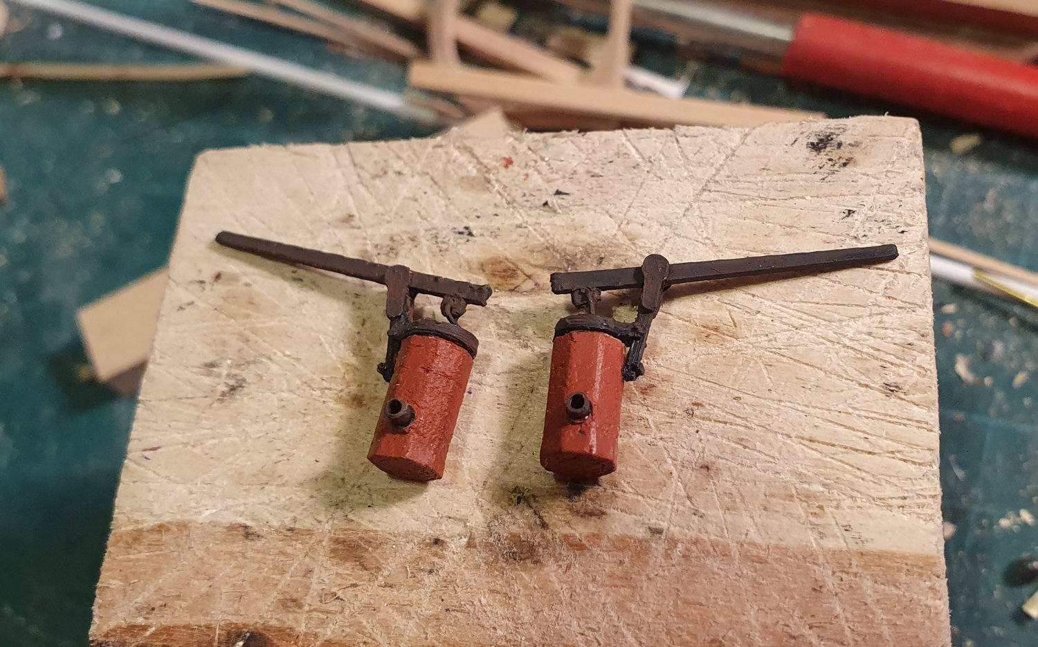
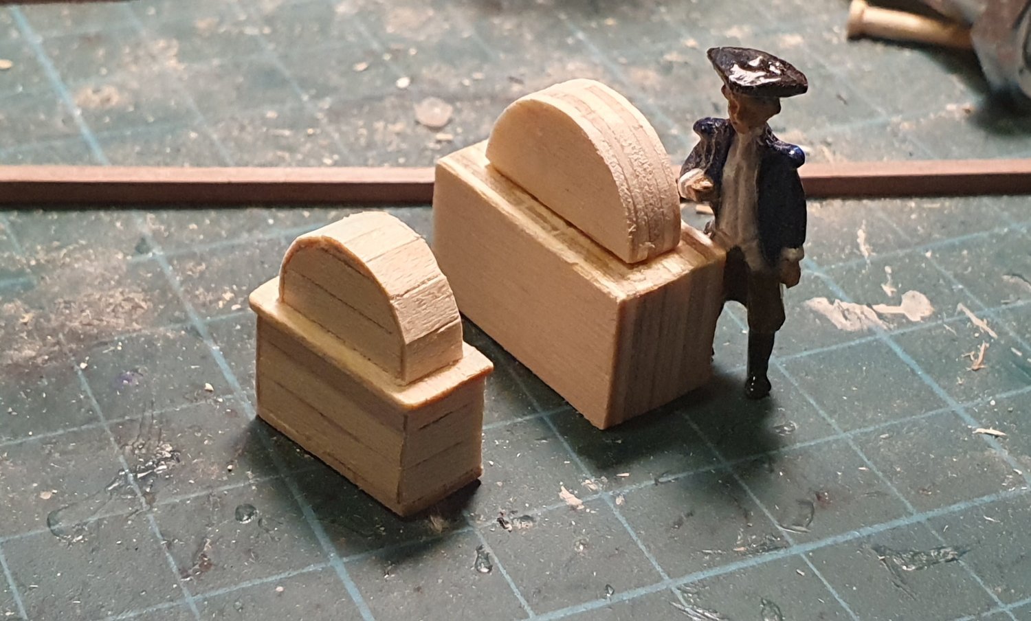
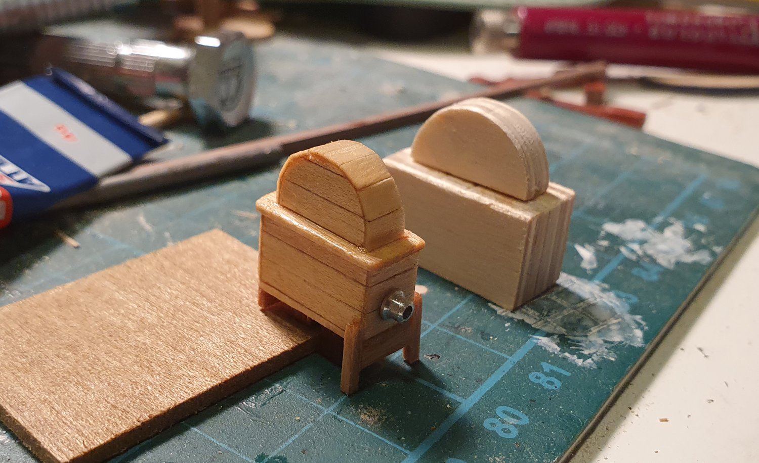
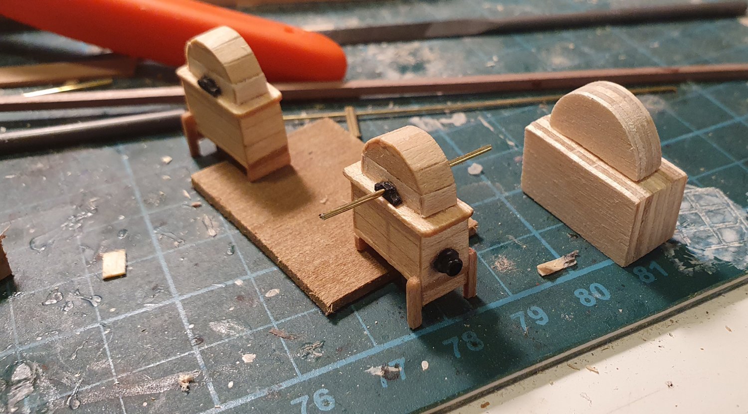
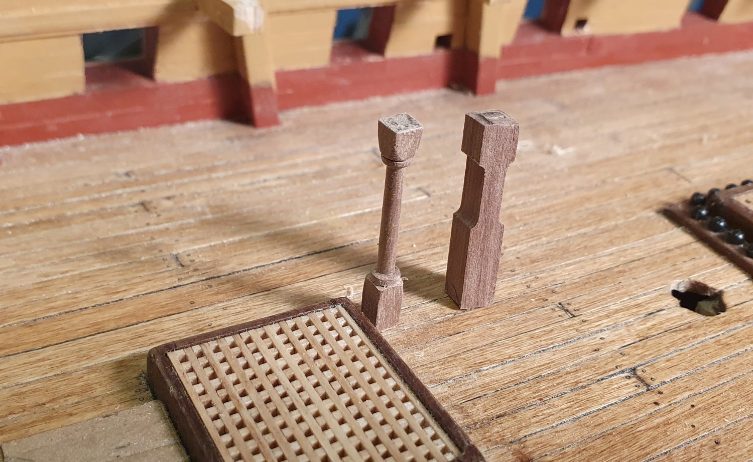
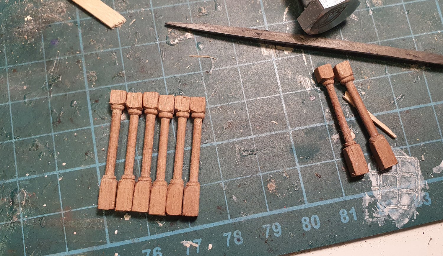
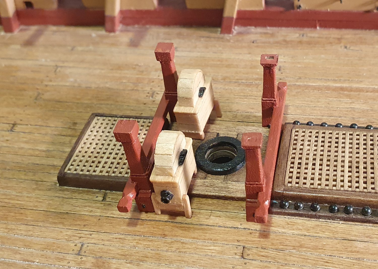
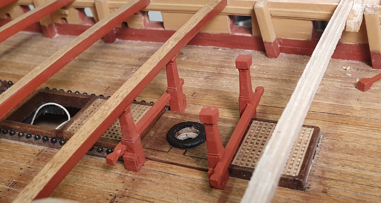
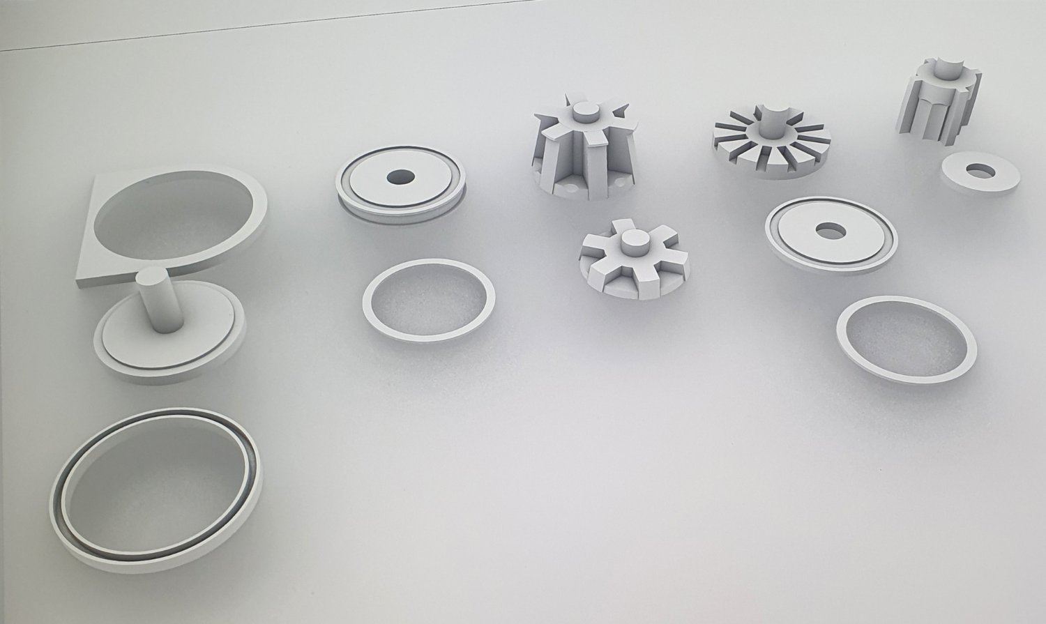
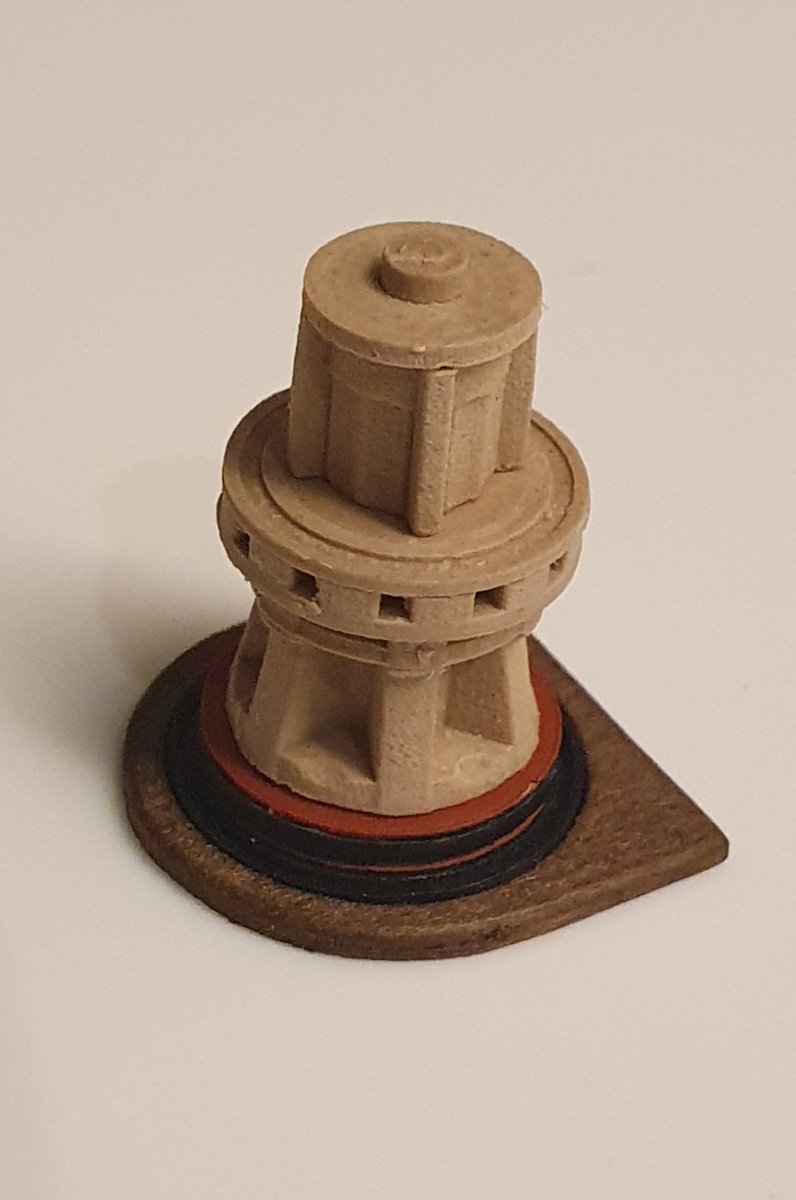
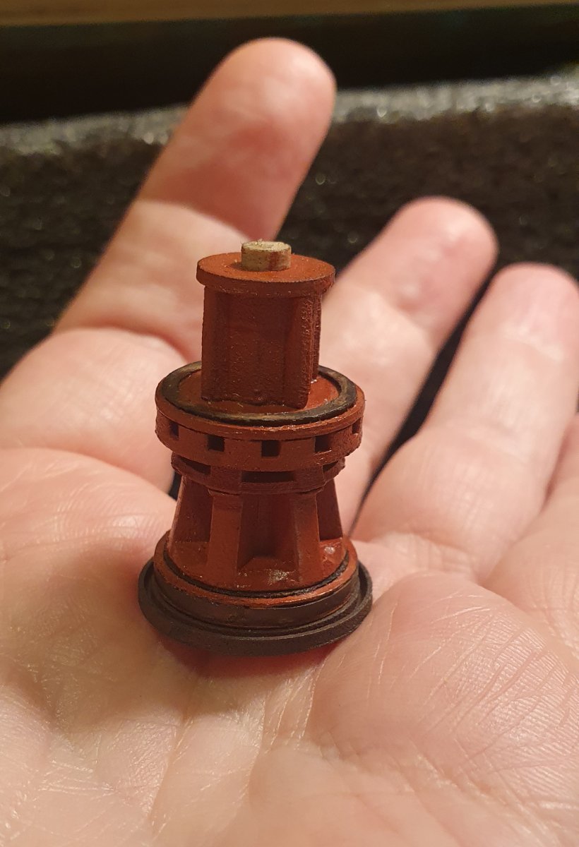
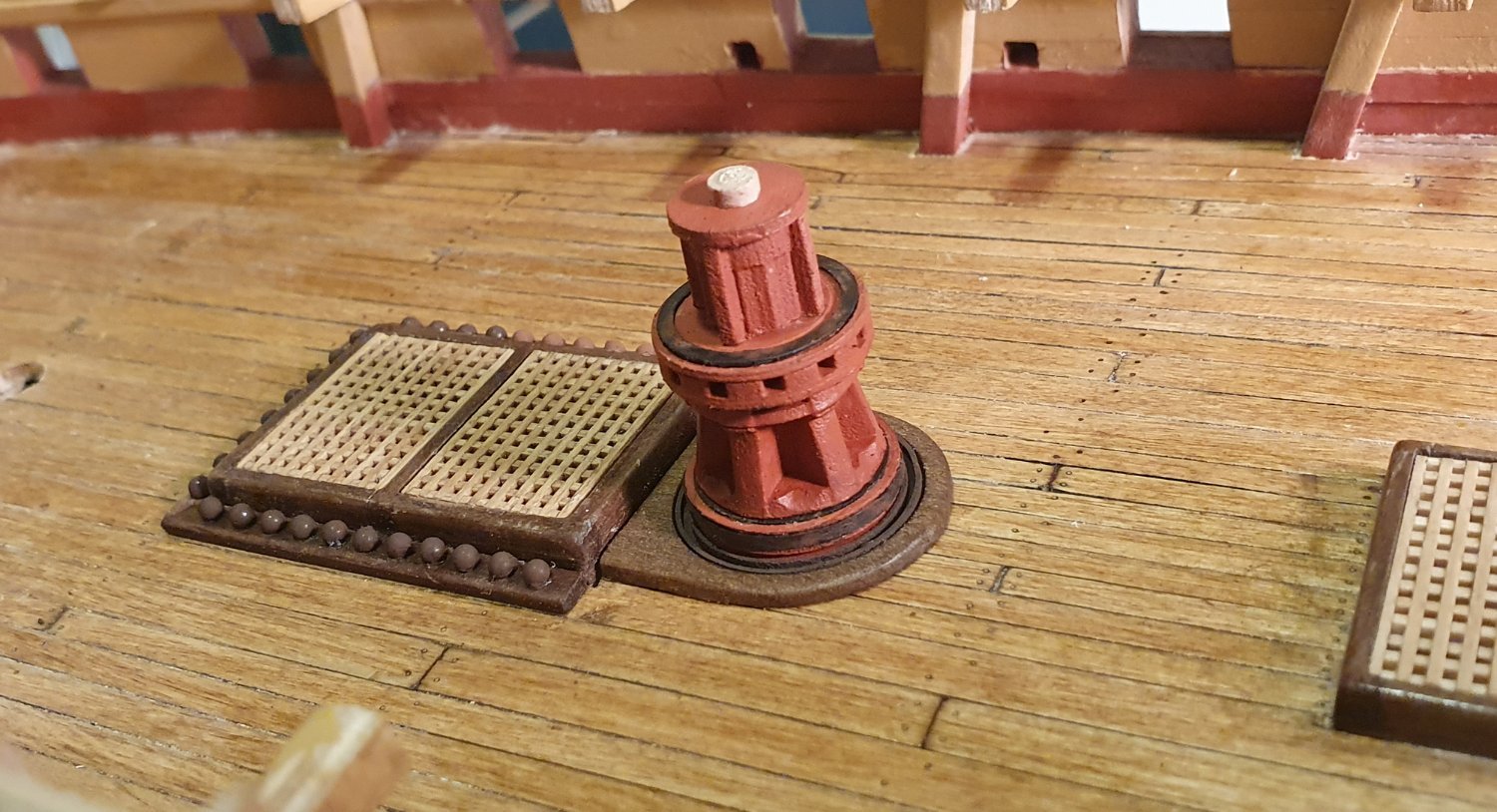
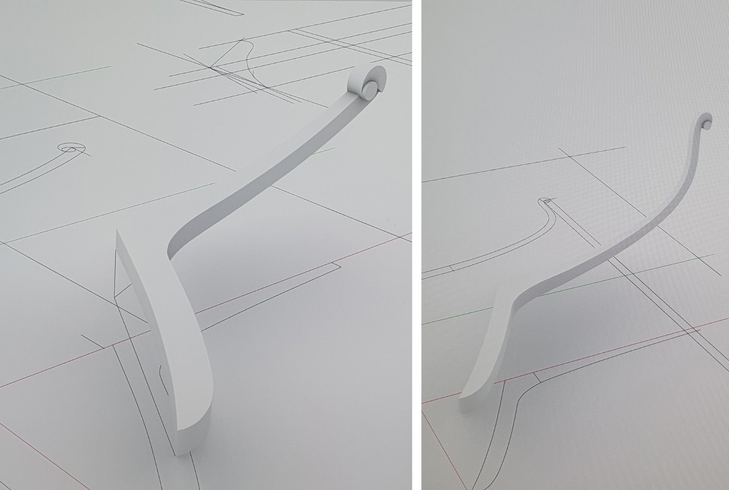
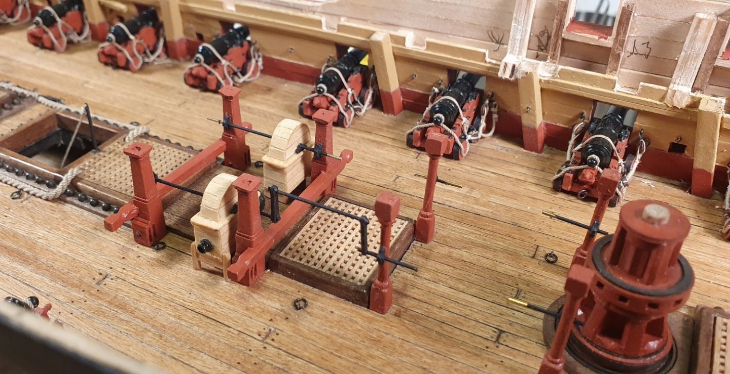
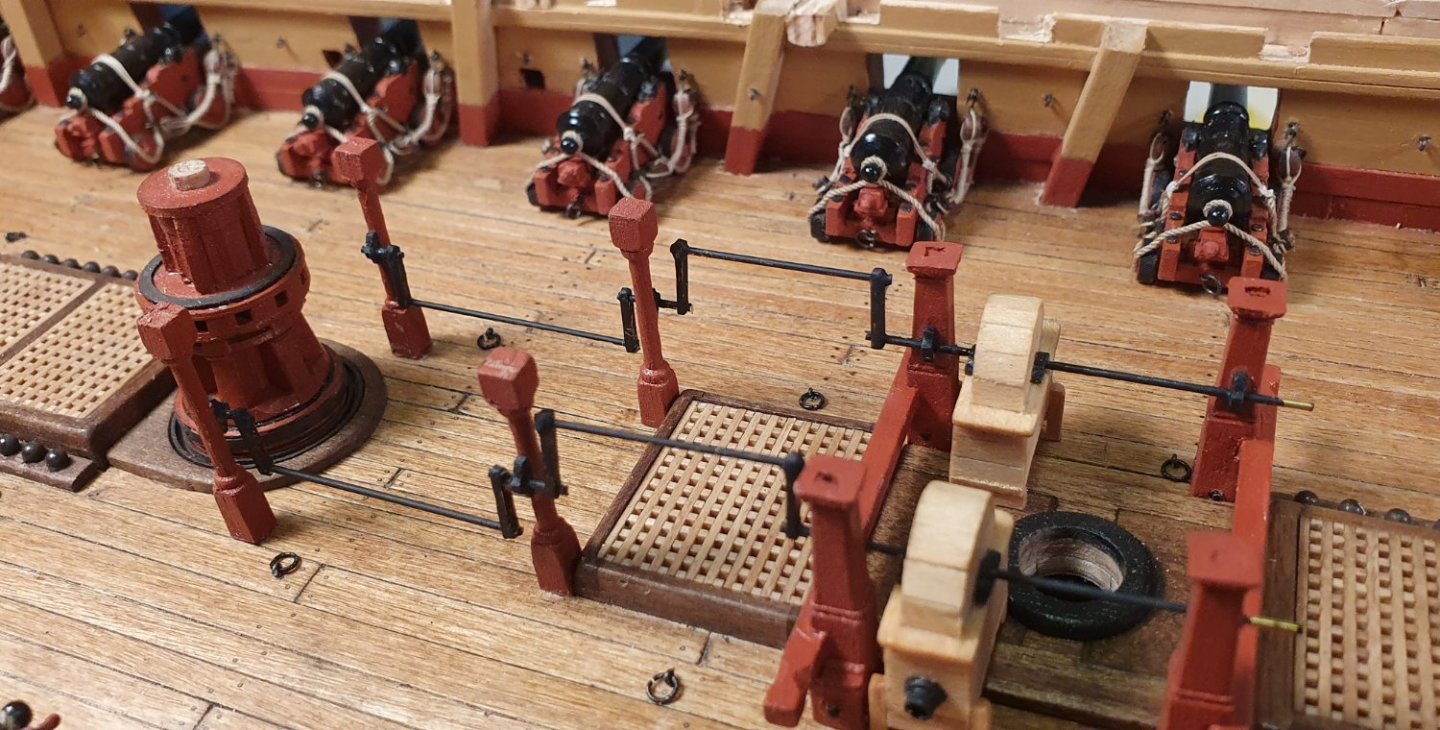
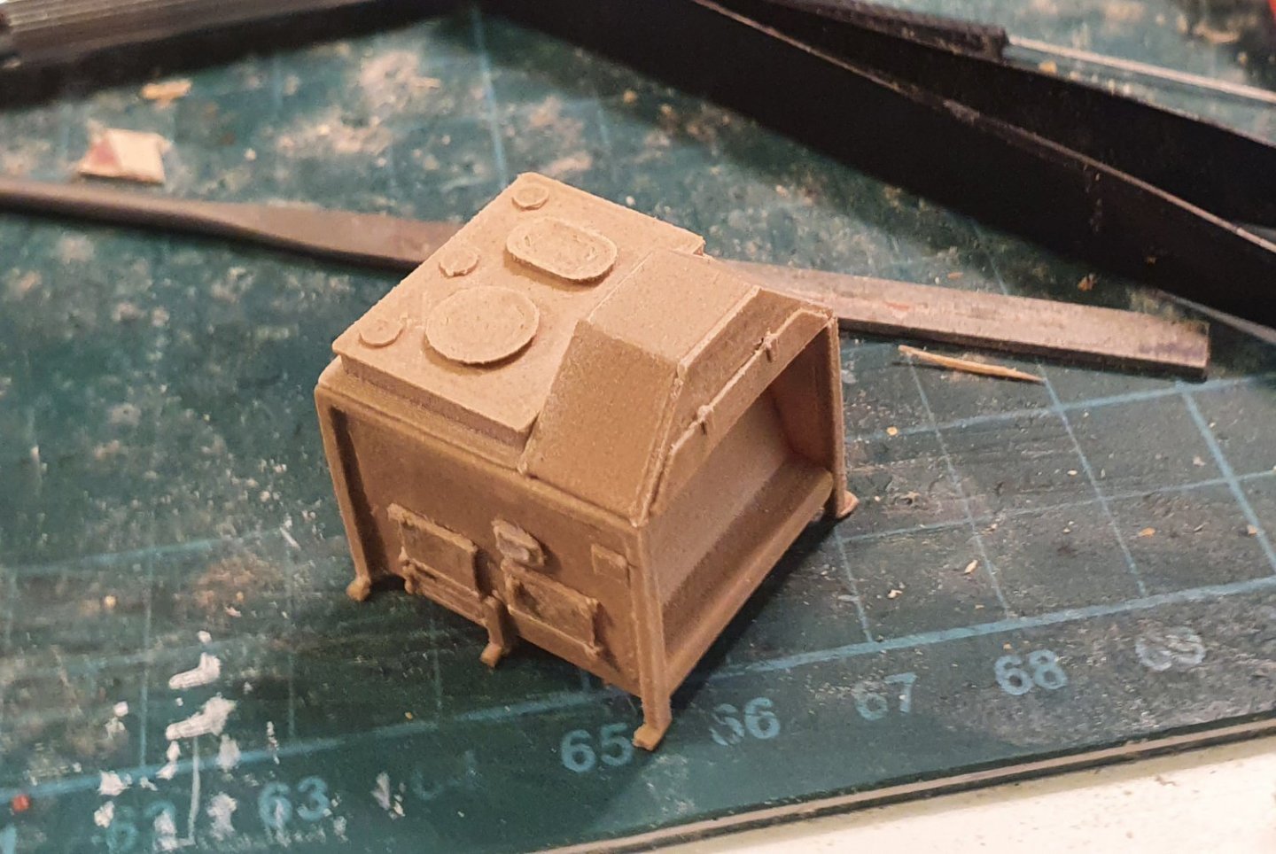
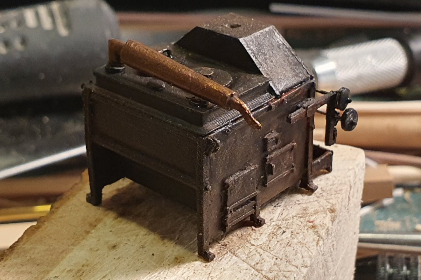
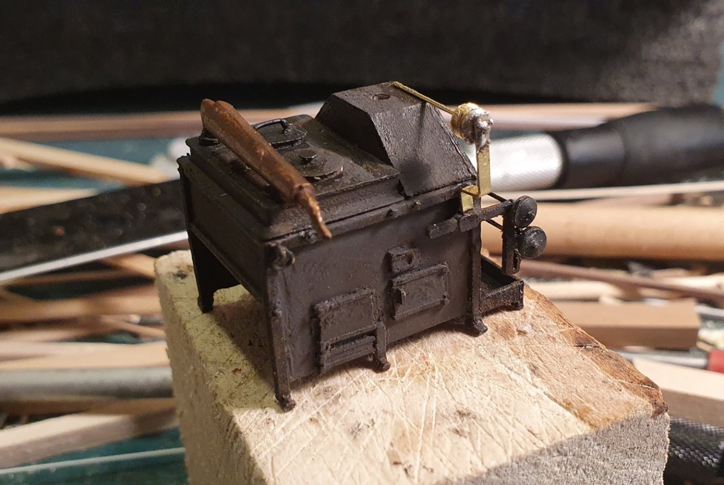
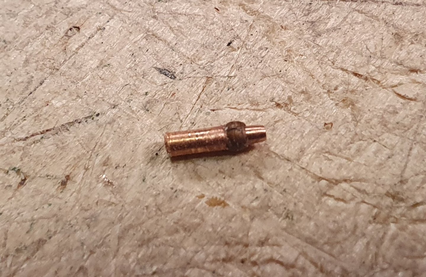
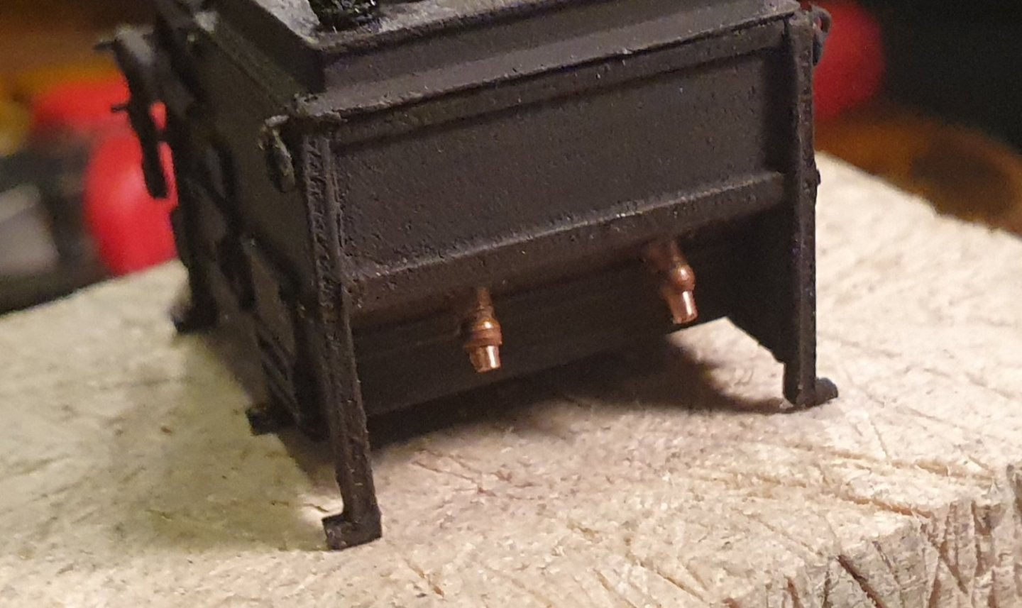
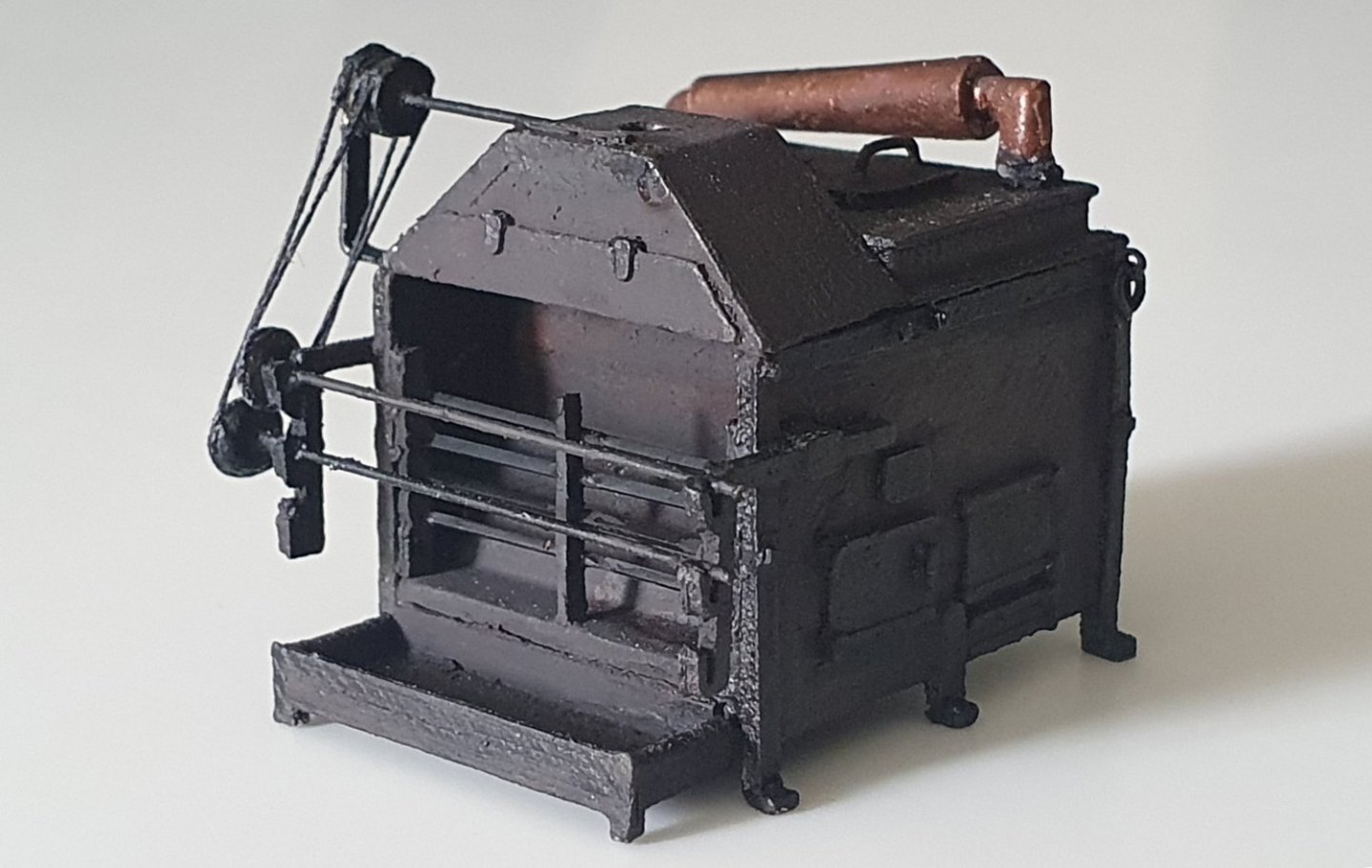
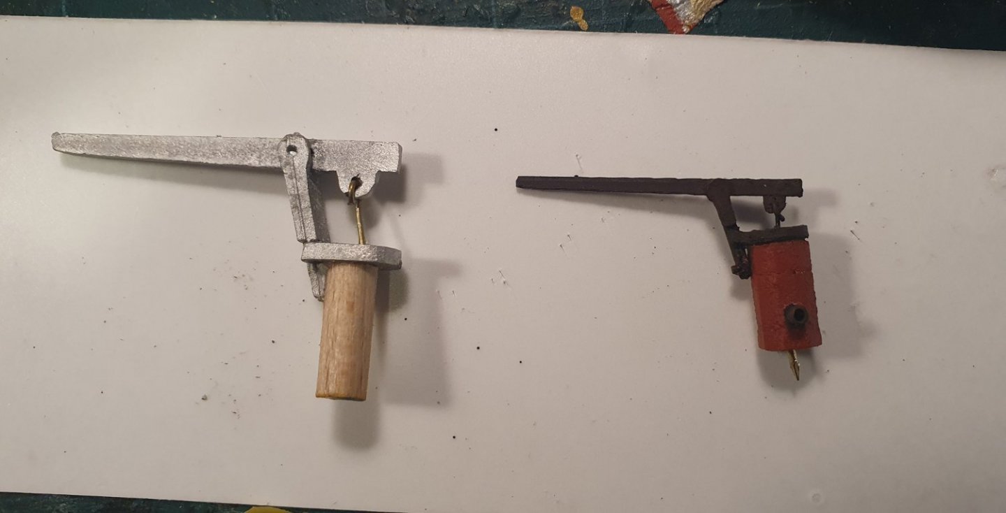
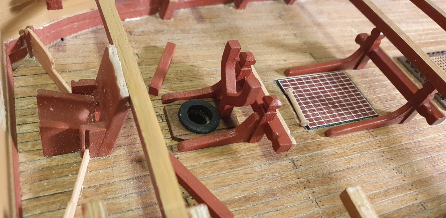
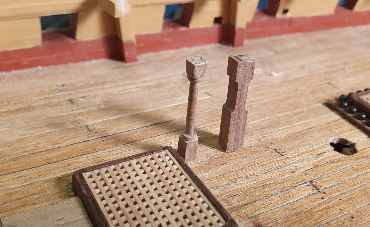
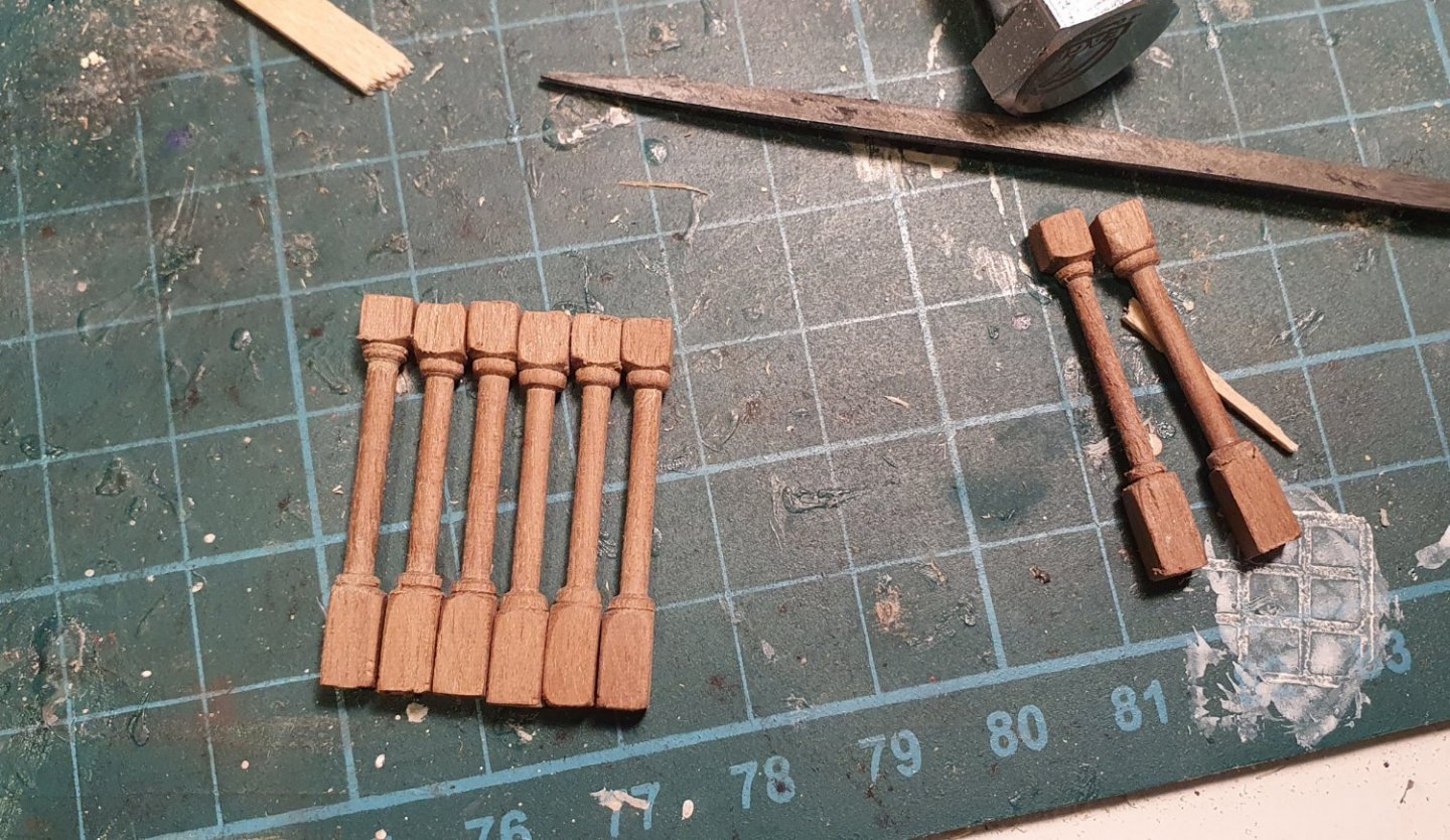
Time for a break from all of the hull work. I started on the various fixtures located on the main gundeck. I noticed that the kit supplied galley stove has been radically simplified which is understandable as it is not really visible beneath the forecastle. Unfortunately the portion that is visible is not built correctly and I thought that I could easily scratch build a replacement as there are detailed drawings in the AOTSD and it did not look that complicated. Turns out it was more challenging than I first imagined. The following is my second version. I started off assembling the carcass using 3D printed parts. In retrospect I should have replaced some of these with styrene to improve the finish. I added some details such as the lid handles using brass rod and nails. I used the kit supplied cast condenser as it was OK. Everyone likes a shawarma so I decided to add the rotisserie. I bent some brass strip for the support and added the spits using brass rod with the chain wheels lathed from larger diameter rod. I built the spigots from some copper tubing which I tapered on the lathe and finished with a faux copper bead. The final product is a little more accurate than the kit part but it is a good thing it is hidden under the forecastle. I then had a stab at the elm tree pumps. Again the kit supplied cast parts looked all wrong. I suspect they are for a larger scale build. I made the handle assembly from wire, styrene and a 3D printed hinge. It is quite tiny and very fragile. The body and head hoop were 3D printed and then the whole thing was painted and assembled. It will be secured to the deck using a pin and a pre-drilled hole. The chain pump cistern and hoods were tackled. No surprises that the kit part seemed too large and had no articulation so I scratch built these. The drawings in the AOTSD were contradictory. Possibly a couple of the drawings were resized at the printers to fit on the page and they do not match up with the stated scale. Nevertheless I had to make up my own dimensions to fit into the available space so as not to clash with the mast and mast step. I turned an aluminium tube on the lathe to form the pump dale but this is a bit too big. The handle bearings were made out of styrene and the pump brakes will be out of 0.8mm diameter brass rod. I will deal with the pump brakes at a later date as they are a delicate construction and I do not want to risk damaging them during the installation of the rest of the deck fittings. I prepared all of the riding bits and the support structures for the forecastle fore jeer bits and fore topsail bits. I thought I was dutifully following the AOTSD dimensions but I seem to have taken a wrong turn somewhere and they ended up a bit thin. These are also not that visible so I will just go ahead and use them. The eight interior columns that come with the kit are laser cut out of 5mm walnut and are quite basic in their detailing. The AOTSD indicates there are two types of column. Four slender round columns located near the capstan and four more robust square columns surrounding the main mast. I turned the circular columns on the lathe using 4 x 4mm walnut. I went mad and made eight of these so that I would have a good chance of getting two matching pairs. For the other columns I resorted to 3D printing so that I could get some of the finer detail and integrate the sheaves into the base. The kit capstan is not a complete disaster but lacks some detail so back to the CAD and the AOTSD. I managed to break it down into a dozen pieces that were printed then assembled and painted save for the step which was made out of some walnut sheet. The finish is not great but, again, this is a piece that sits below the quarterdeck and is barely visible. For the upper deck portion of the capstan I will see if I can swap out some of the elements for timber to try and improve the overall appearance.


-
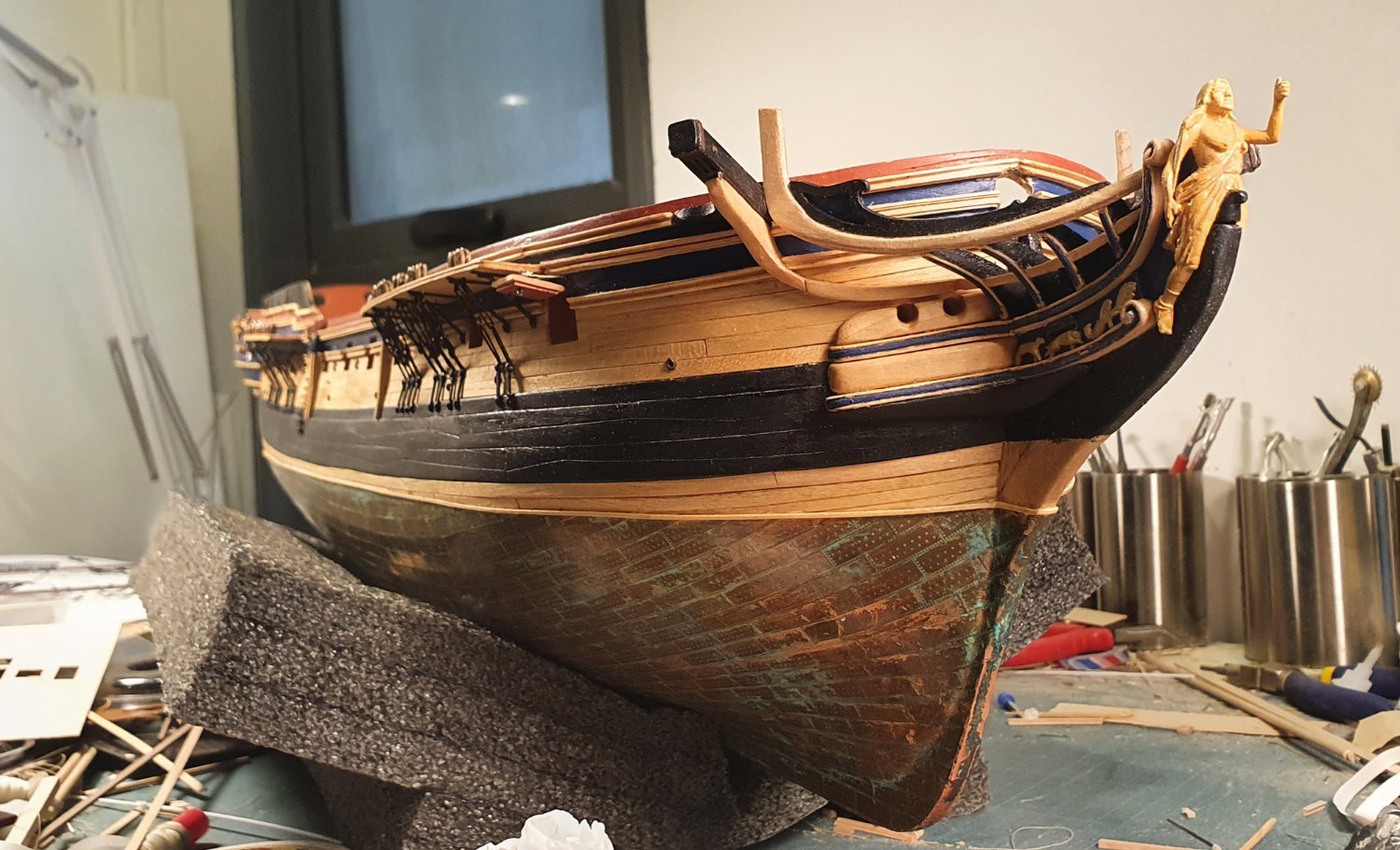
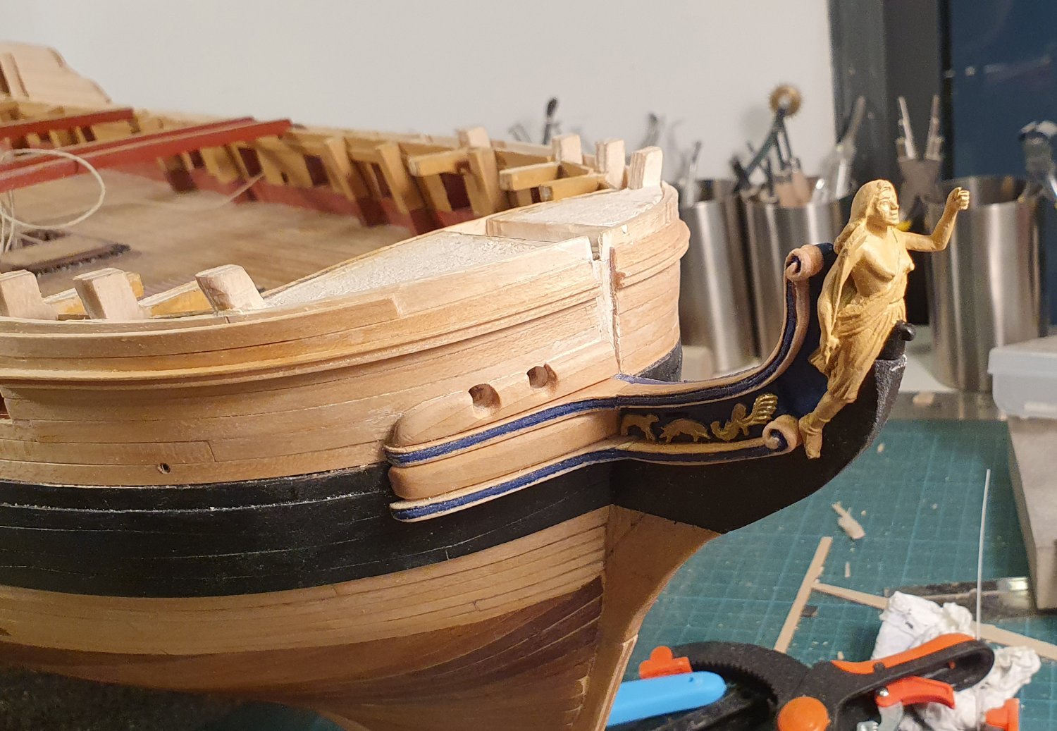
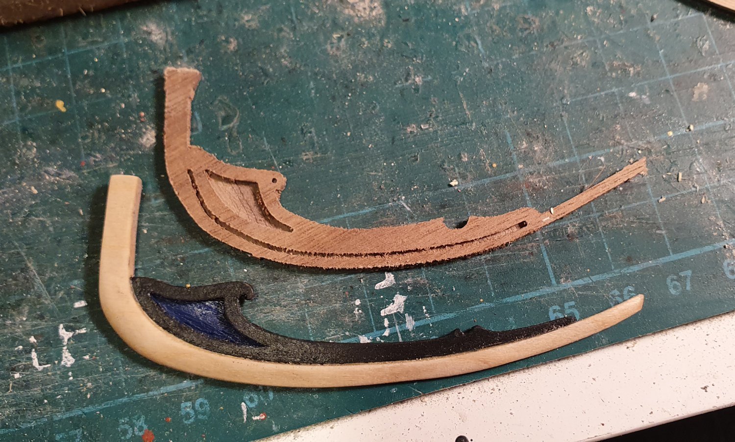
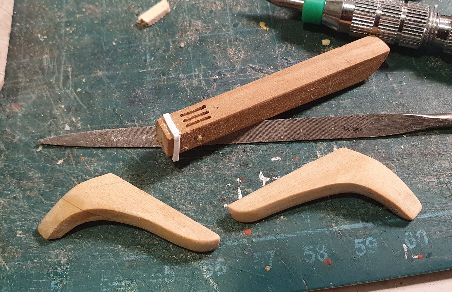
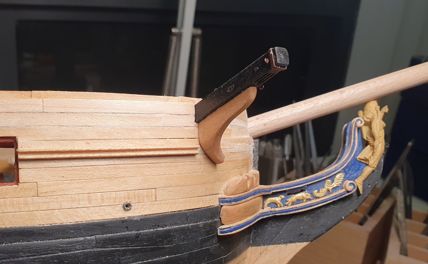
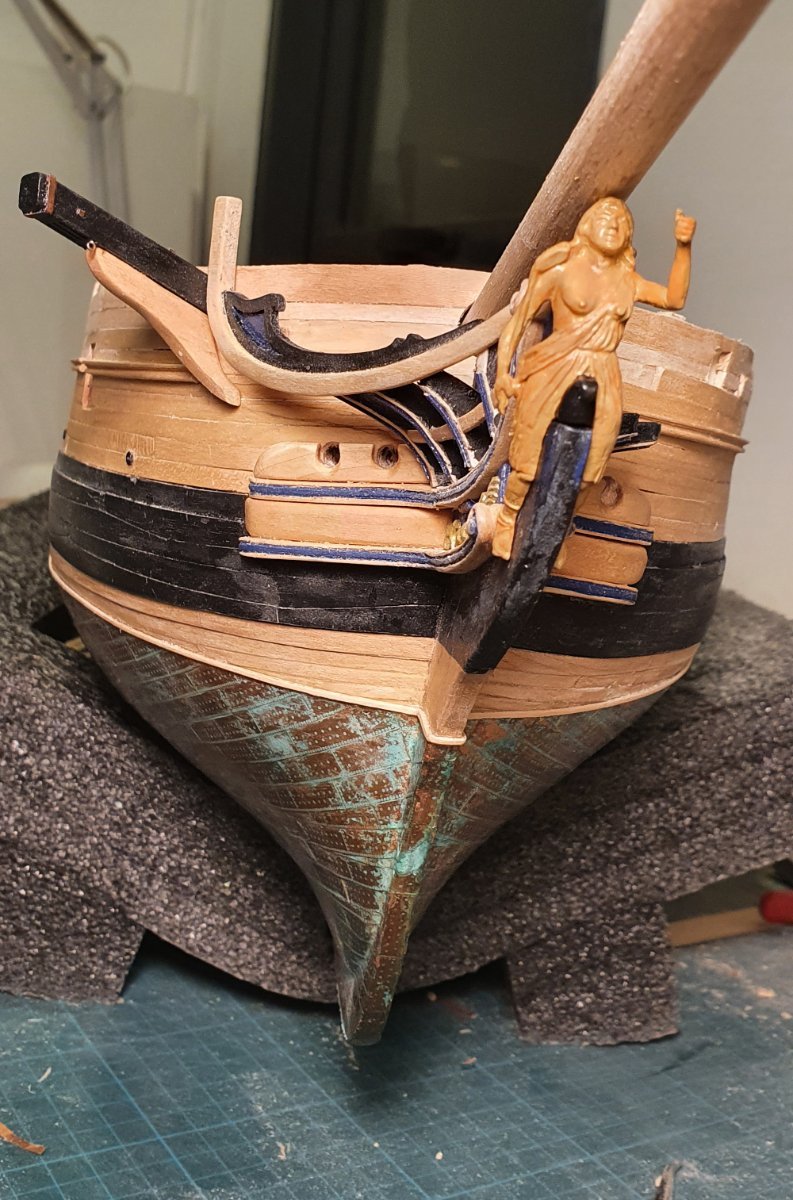
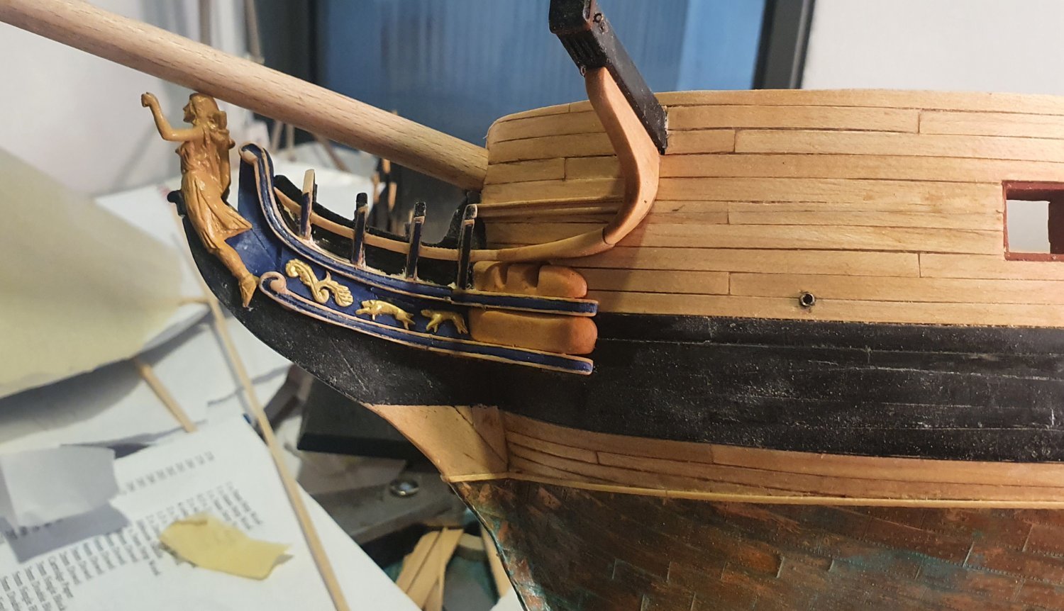
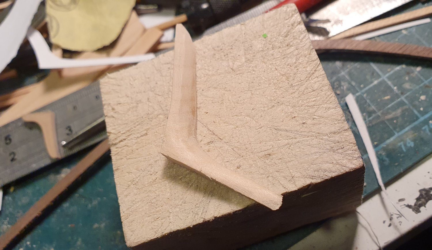
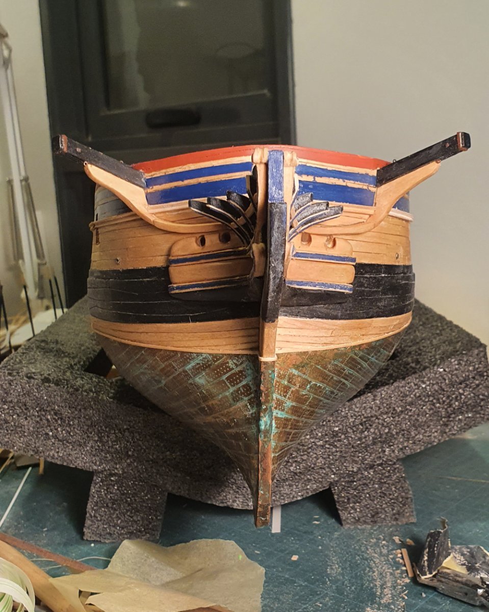
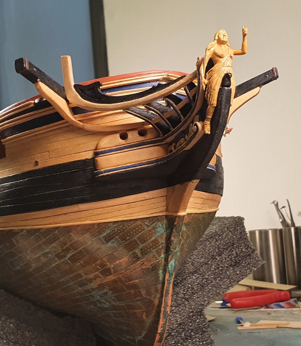
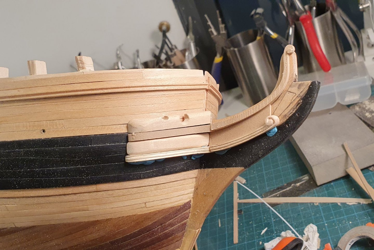
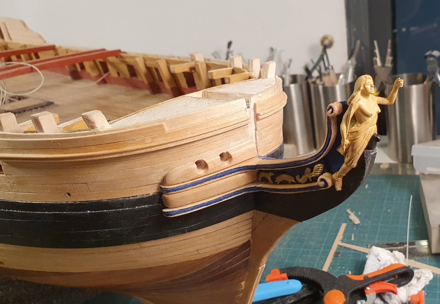
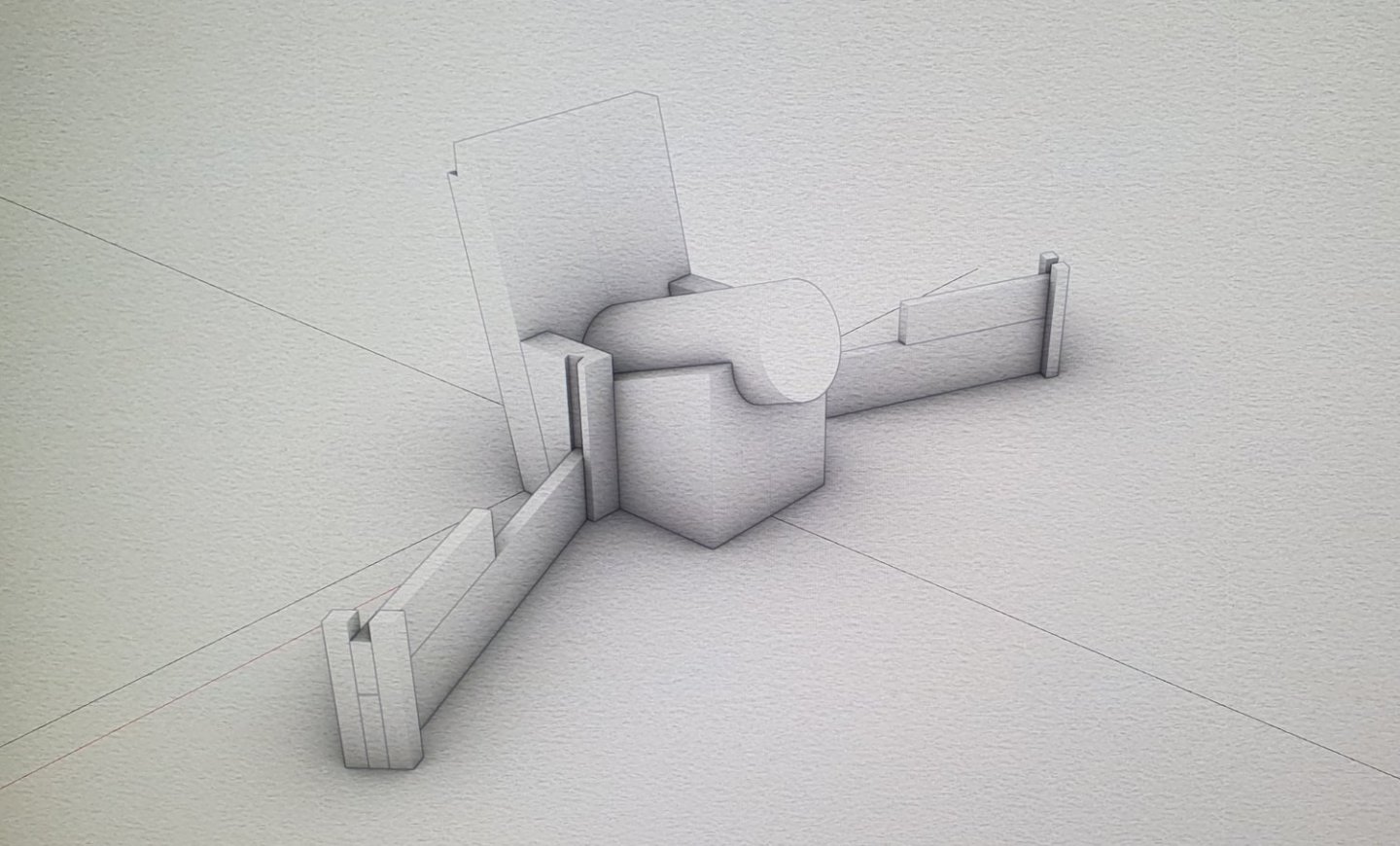
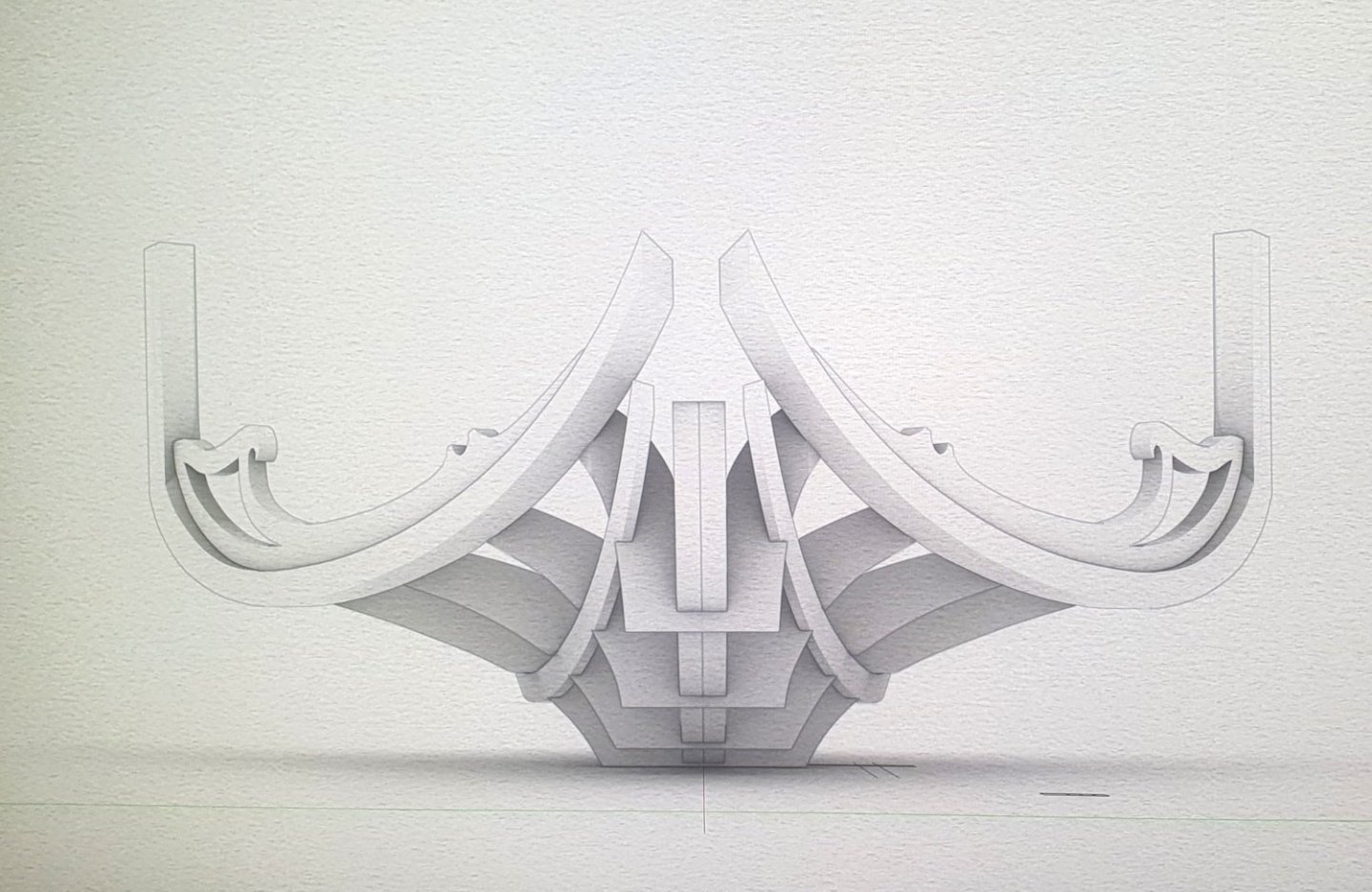
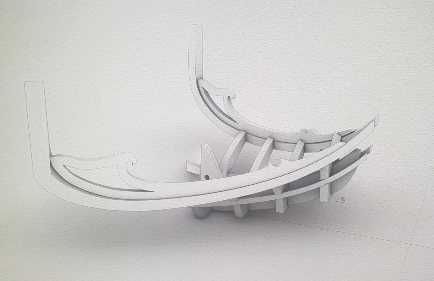
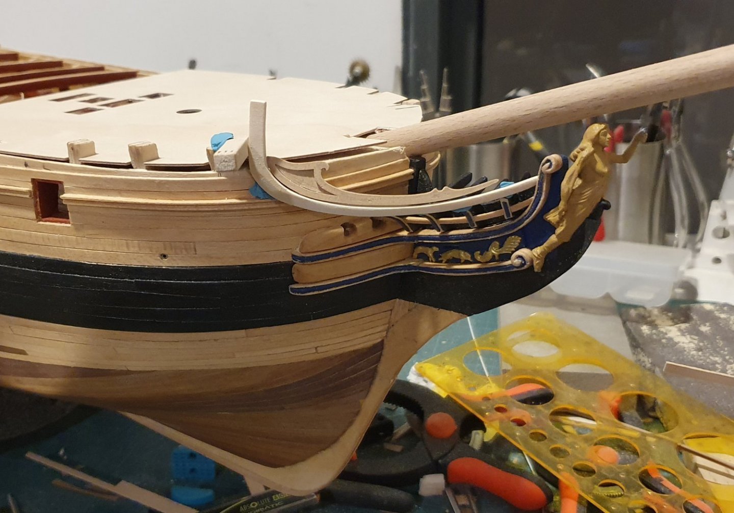
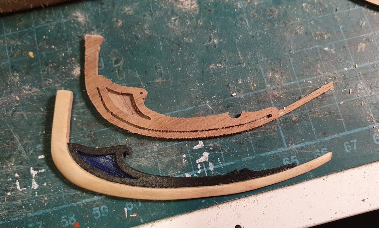
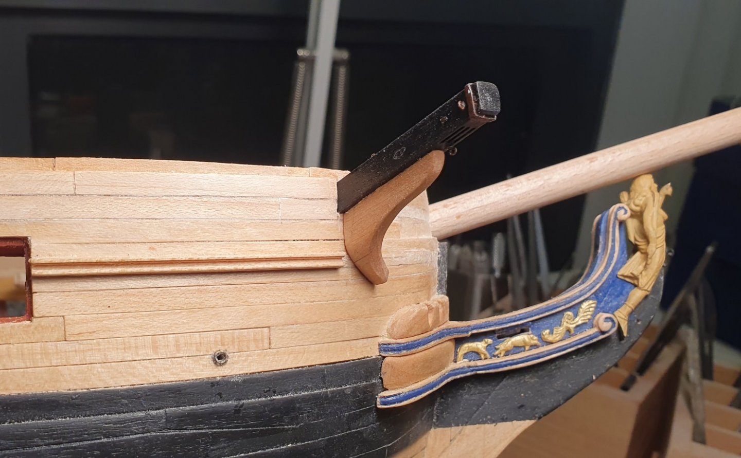
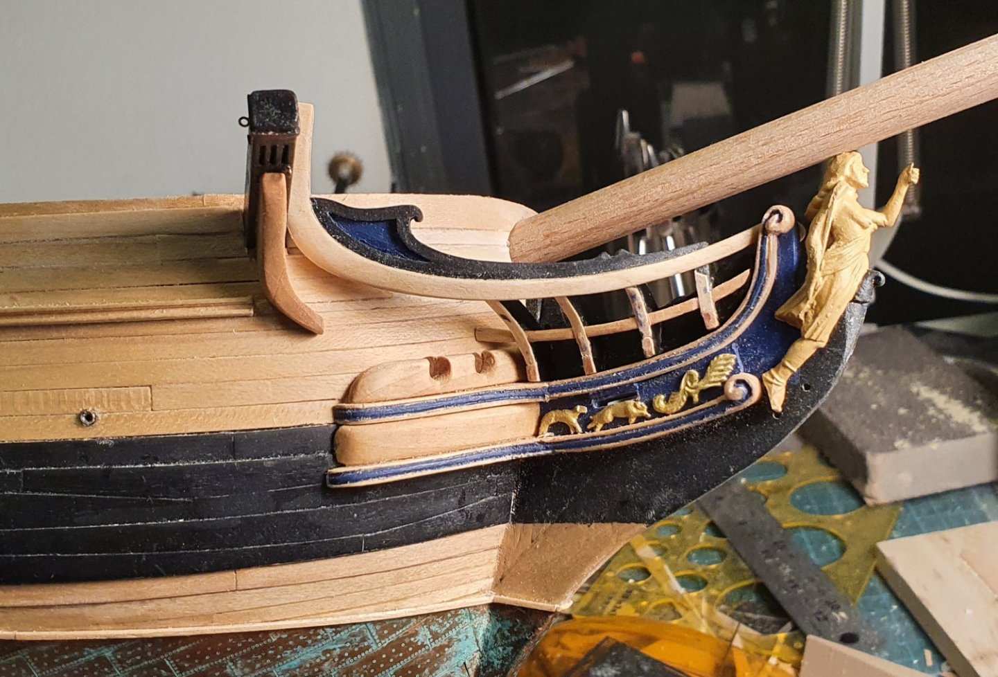
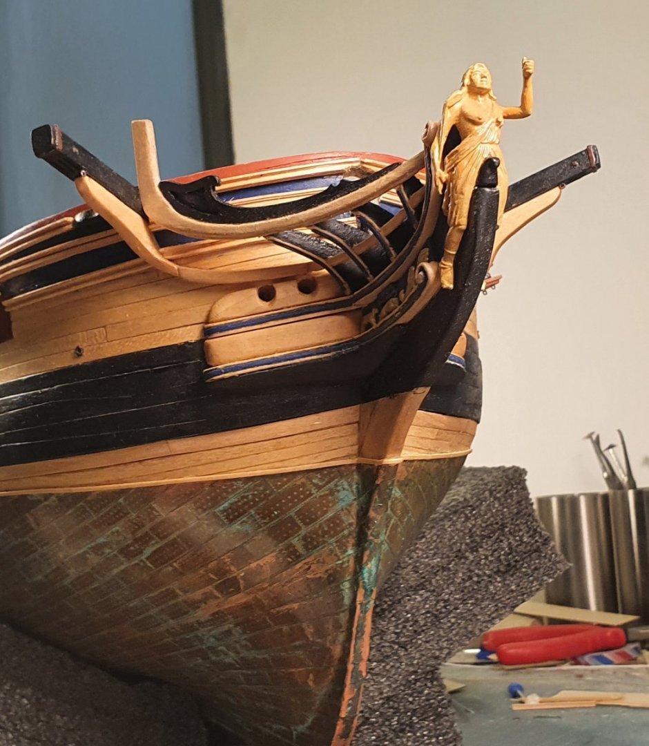
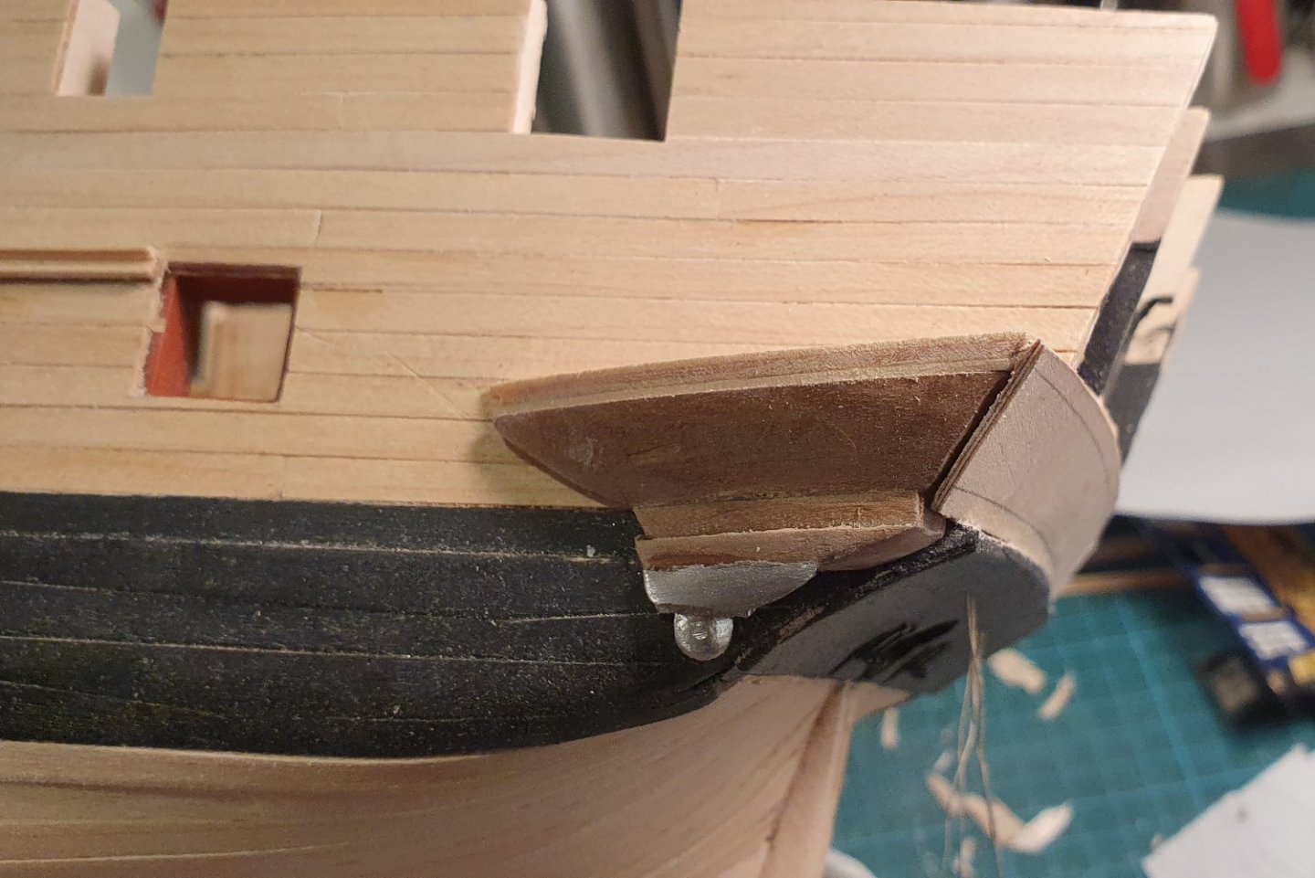
I started to work up at the sharp end. The upper and lower cheeks supplied with the kit were a little thin and didn't quite fit onto the model. I used the drawings contained in the AOTSD to generate a 3D version which was printed out and then used as a 3D template to cut new ones out of some lime wood. The lime was a bit too soft and didn't carve that well. I wouldn't mind a do-over for these but it I fear that it is too late for that. I added the hawse bolster and filling piece using the dimensions in the AOTSD. I also resorted to the CAD to mock up the bowsprit step and manger boards. Here I added a block to help me get the correct angle for the bowsprit. This is not an authentic part but I had a peek through the gunports and it is not really visible so I can sleep easy. I drew up a new profile for the gammoning knee and head timbers. I then printed this out and made up one using a combination of timber and 3D printed parts. The end result is only marginally slimmer than the kit supplied parts but I think that it is an improvement as it takes care of the exposed plywood edges. I printed out the lower rails and then used them as a template to shape some maple efforts. I mocked up the entire head structure so that I could work out the dimensions of the main rails. Once printed out these were used to construct timber ones. I kept the 3D printed part for the false rail as it proved too fiddly to make out of timber. The revised parts have a bit more definition than those supplied with the kit but are still missing some fine detail that I struggled to add. I built the catheads from scratch out of walnut as I didn't like the laminated kit part which was also the wrong size. I carved the cathead supporter from a block of lime. I added the trailboard and gammoning bolster to fit between the cheeks. I had to increase the length of the gammoning slot as it conflicted with the position of the head timbers. I also had to rearrange the order of the small decorative animals as there was not enough room to fit the tall one (sheep?) under the gammoning slot. I constructed the ekeing more or less in-situ to fit between the cathead supporter and the lower rail. The transition between these is quite clumsy but I was losing the will to live by that point. The catheads were finished off with the addition of the cathead knee, various eyebolts and a thumb cleat for the cathead stopper which was carved out of styrene. The wash cants were formed out of a block of lime using a sanding drum on the dremel. These are a bit ropey but luckily they are painted black so are not that visible. Looking at the model head on you can notice some wild asymmetry happening but I can claim wabi-sabi. I will leave the gratings, seats of ease and iron horse for another day as they look quite fiddly and I need to recuperate.


-
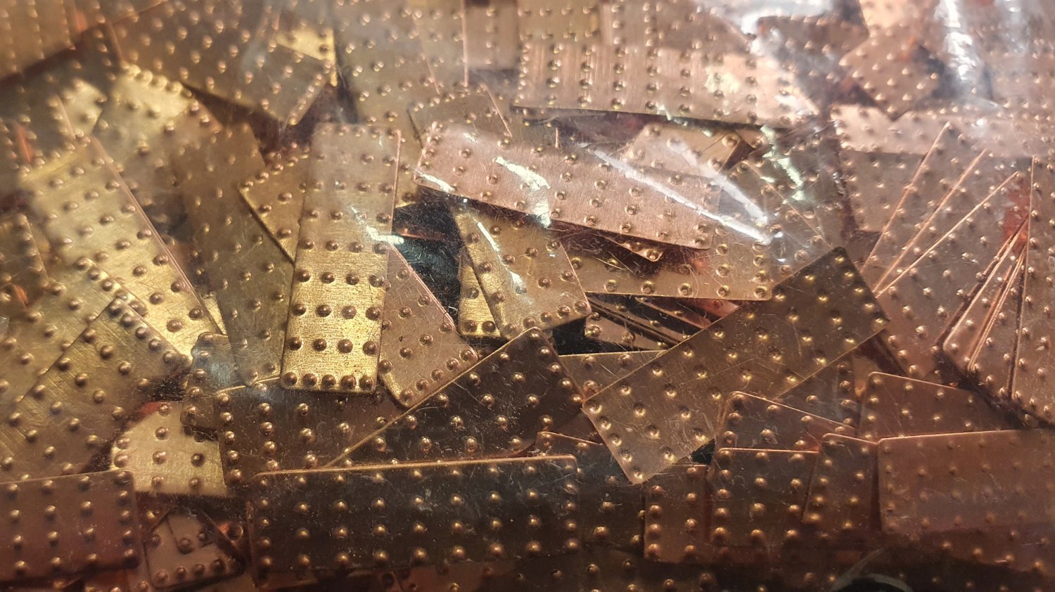
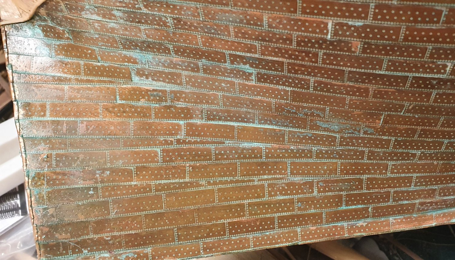
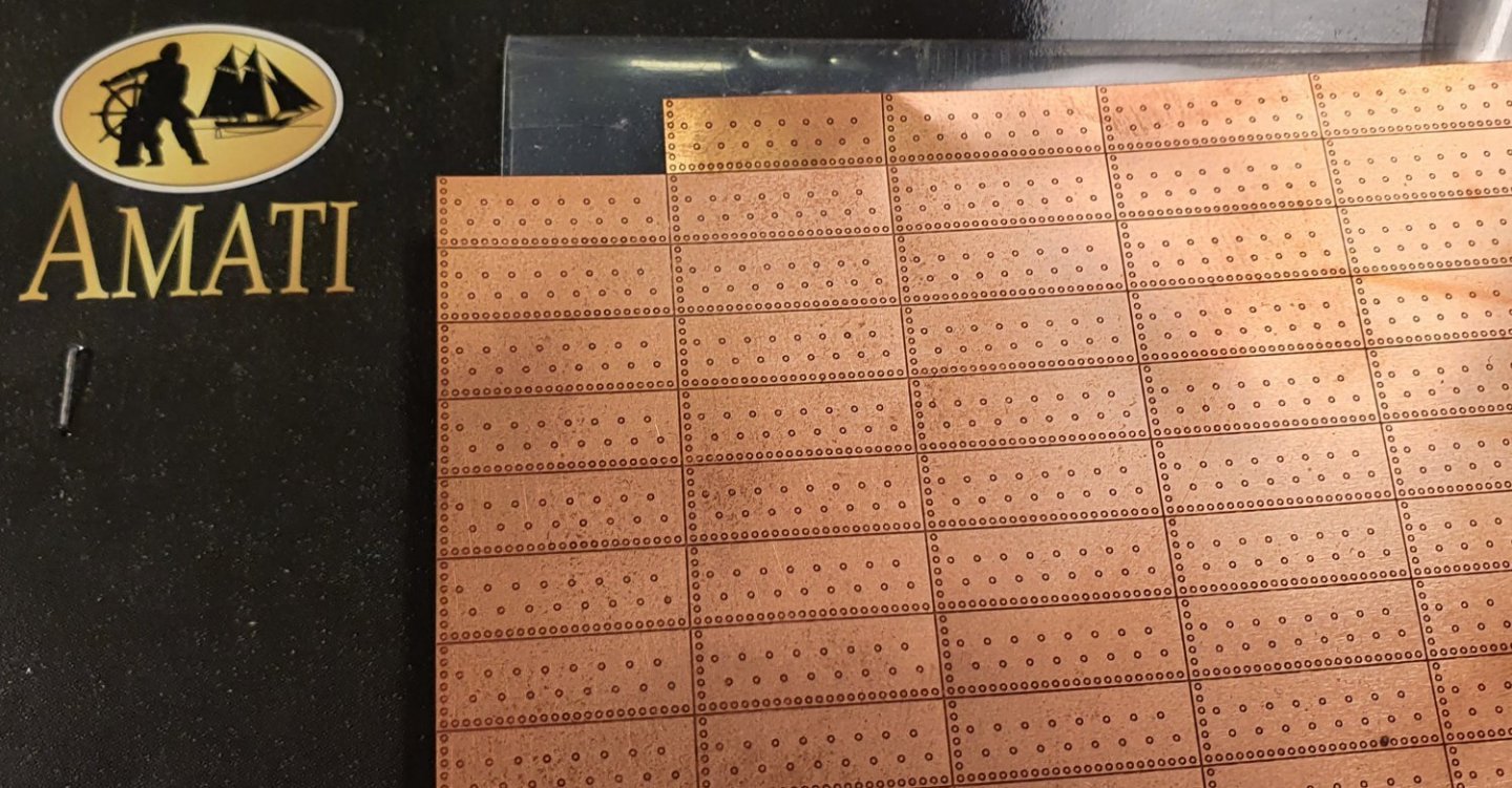
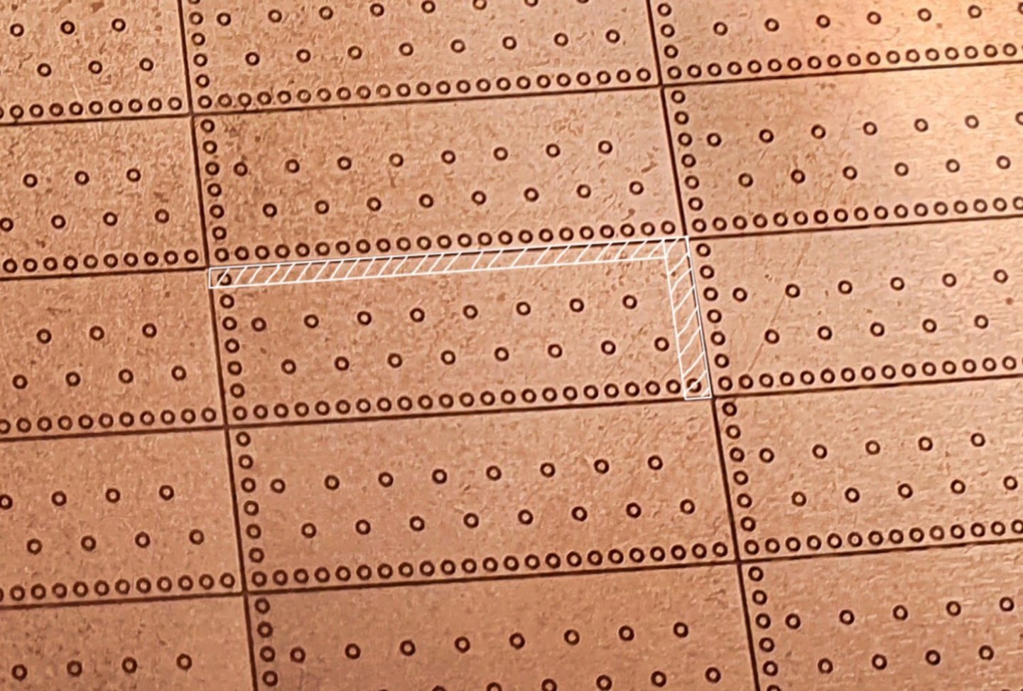
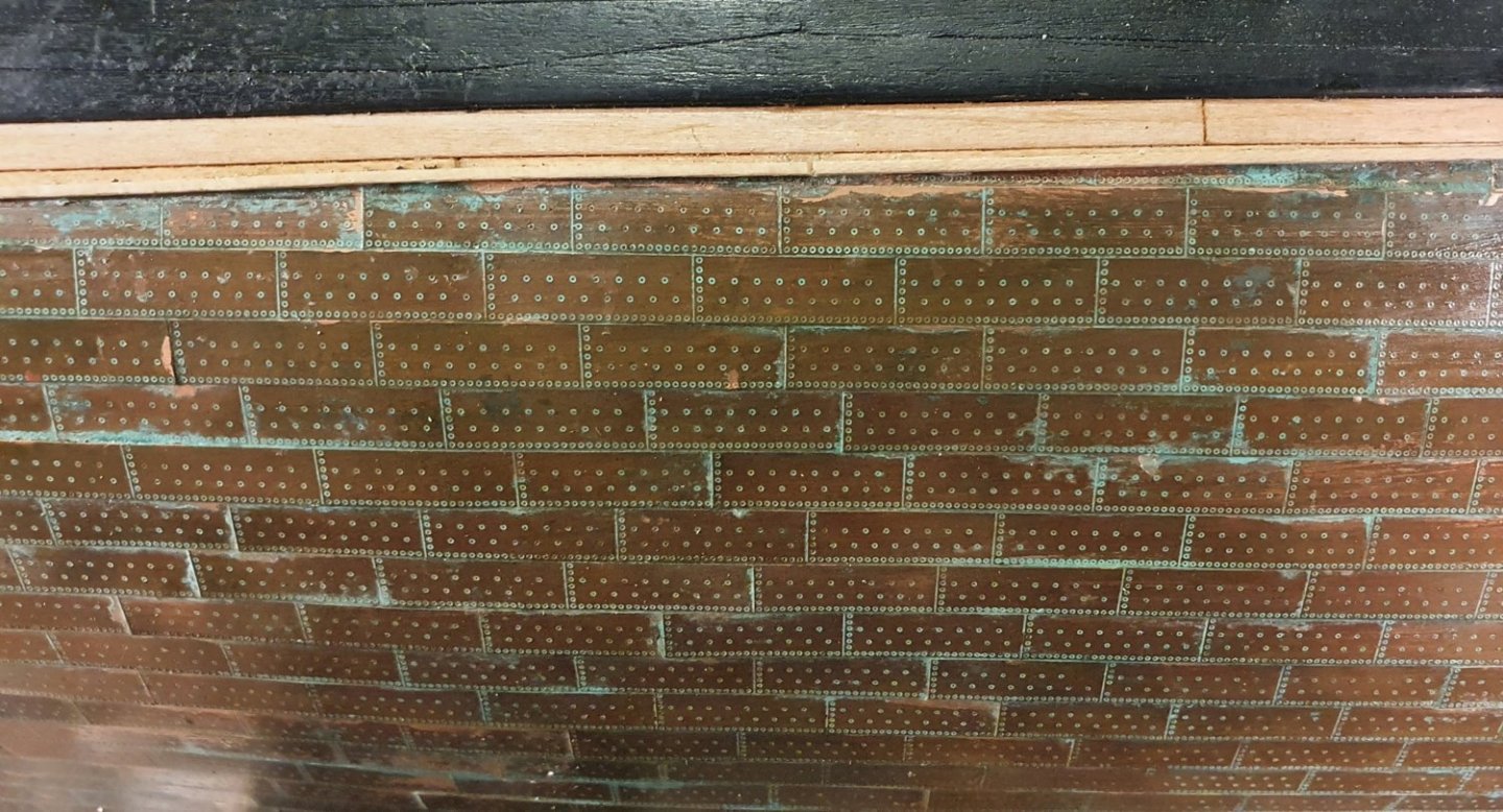
Yes they are somewhat oversized. I think that the effect that they were trying for is that outer ring, which is etched into the metal, represents the dimple in the copper caused by driving the nail in. The circle in the centre would then represent the nail. I agree that a simple smaller dot would probably look better. I guess that I could always do some homemade photoetch as there are some tutorials on the internet that show one how to do it. Regards, David
-
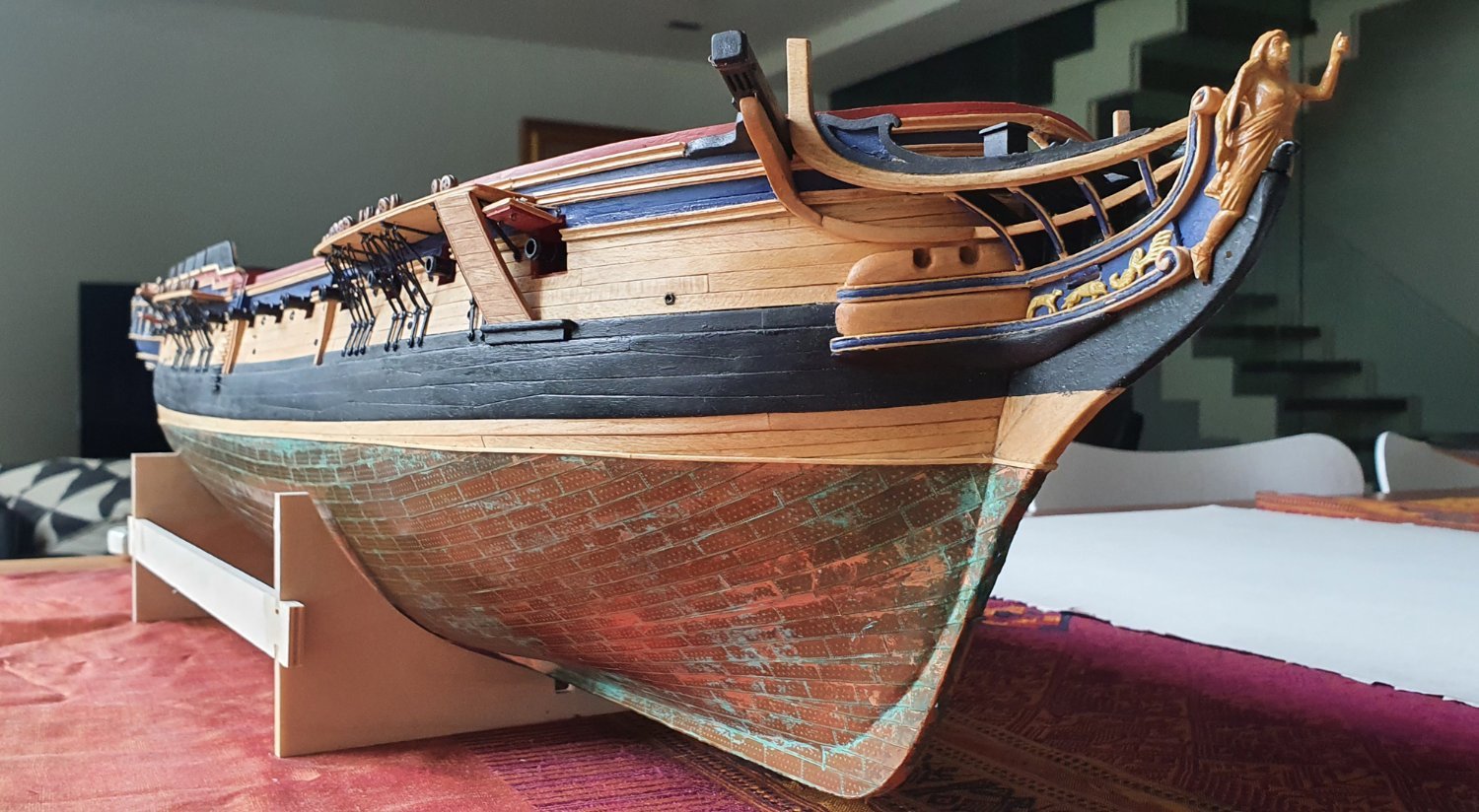
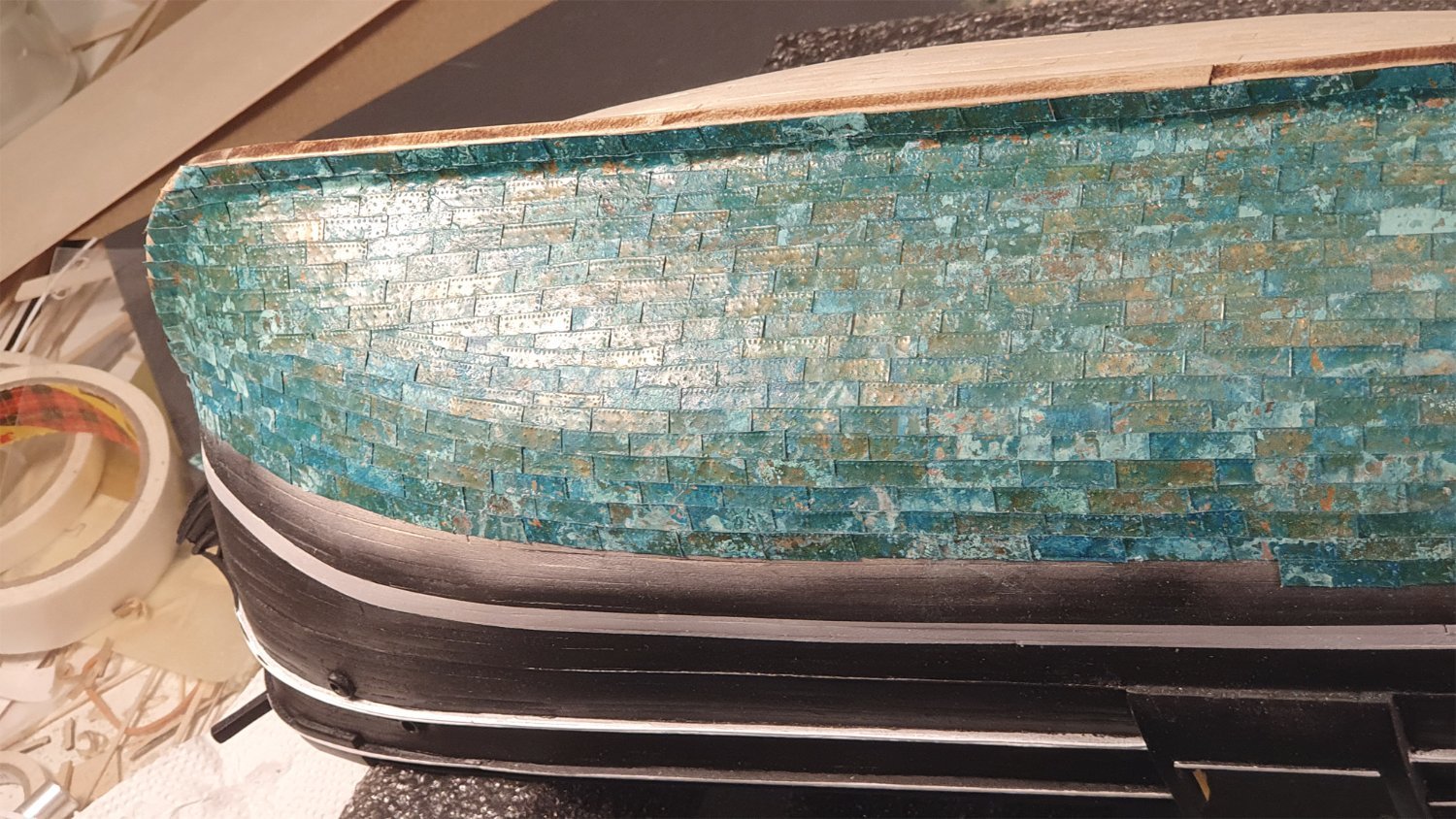
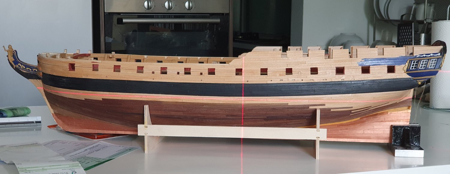
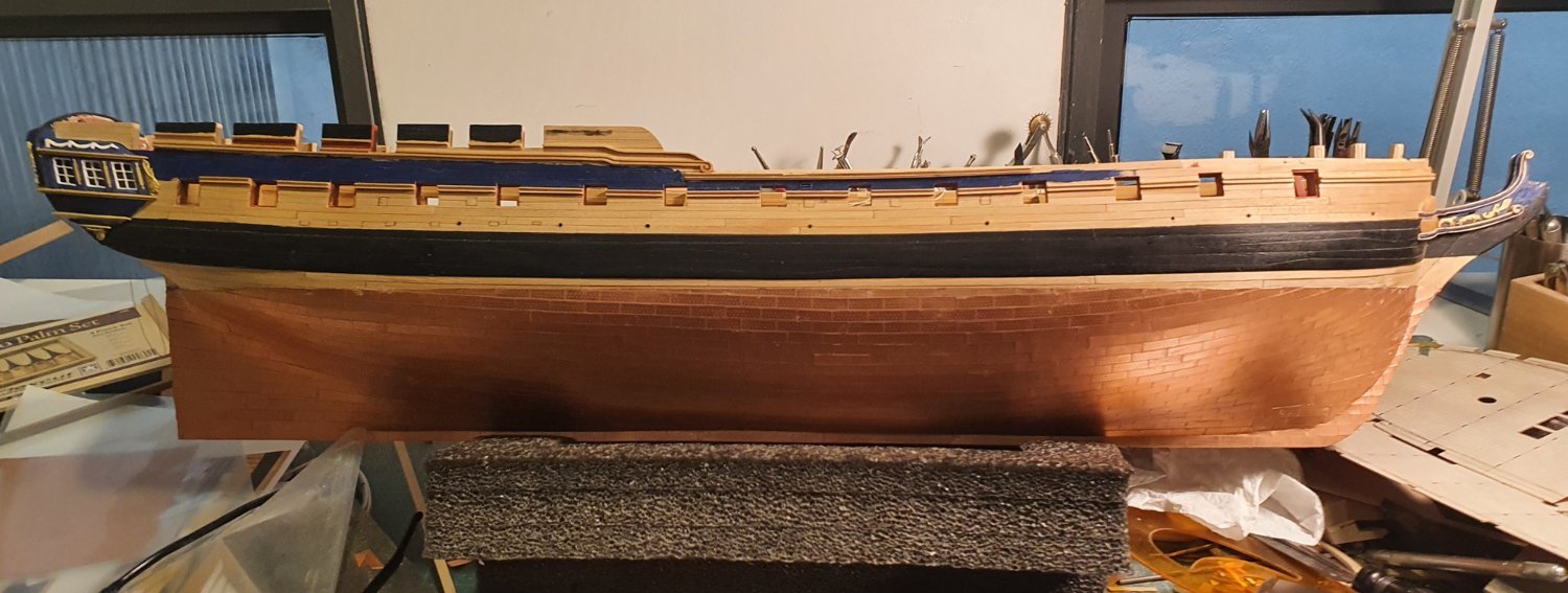
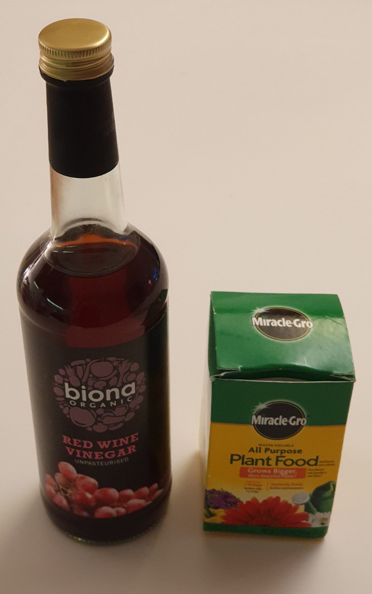
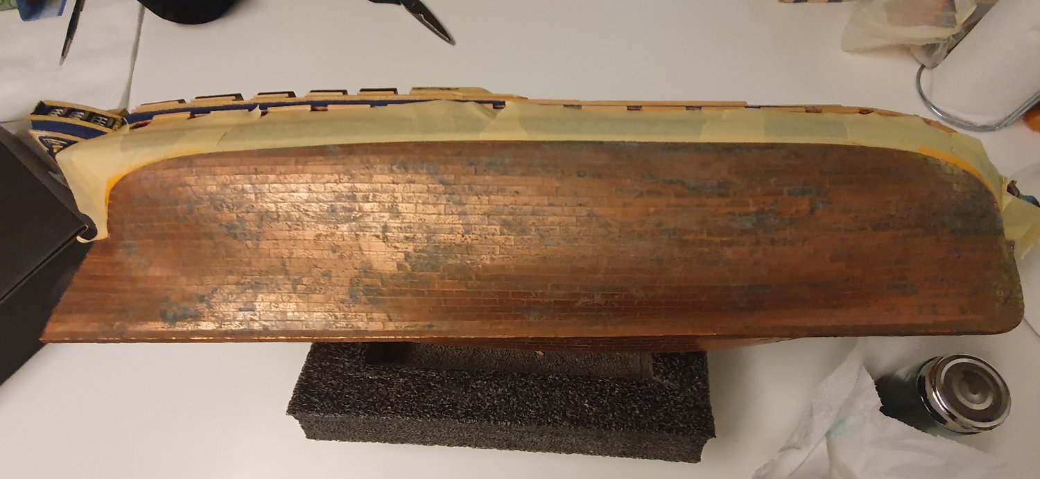
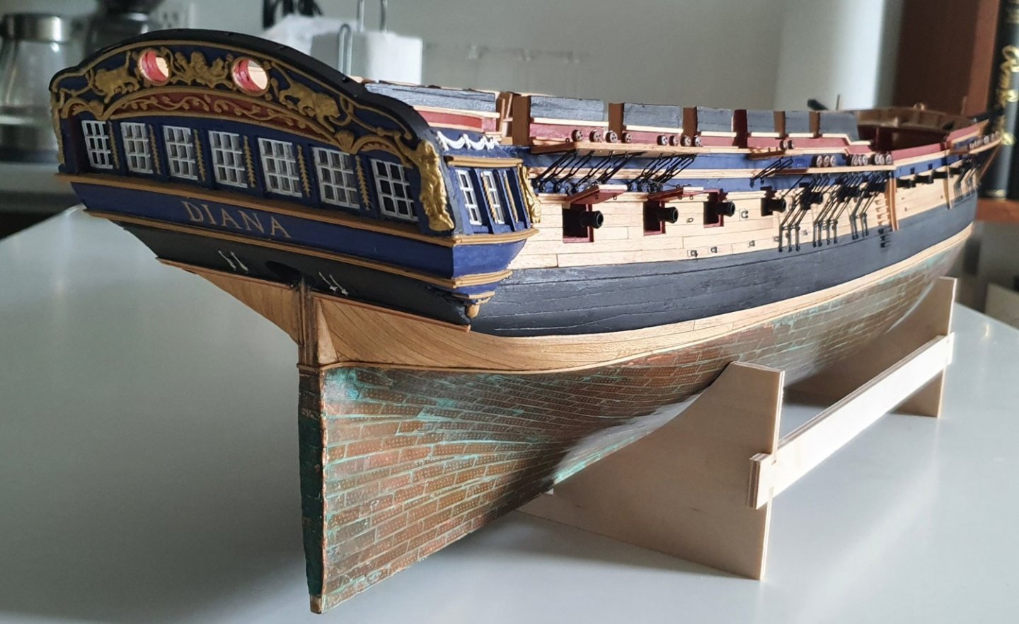
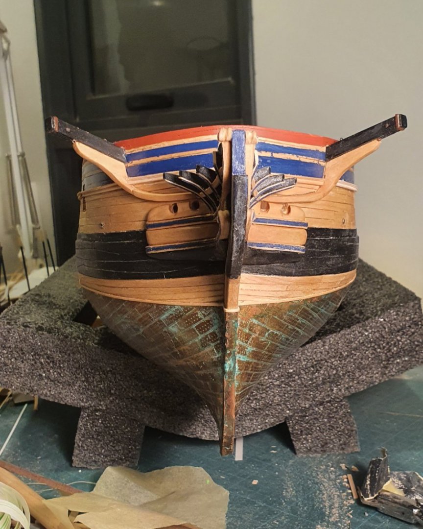
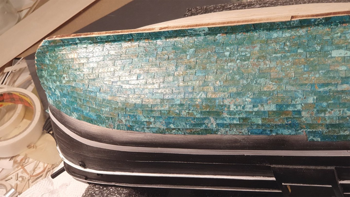
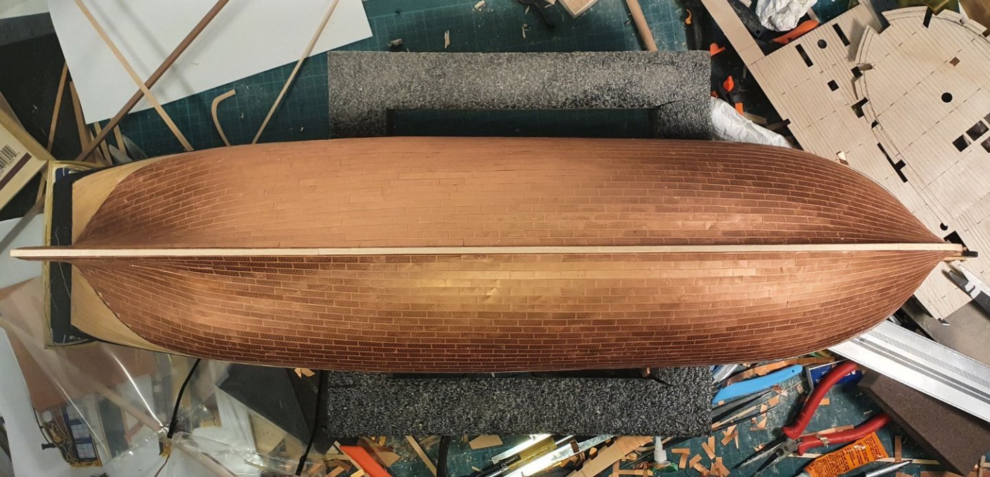
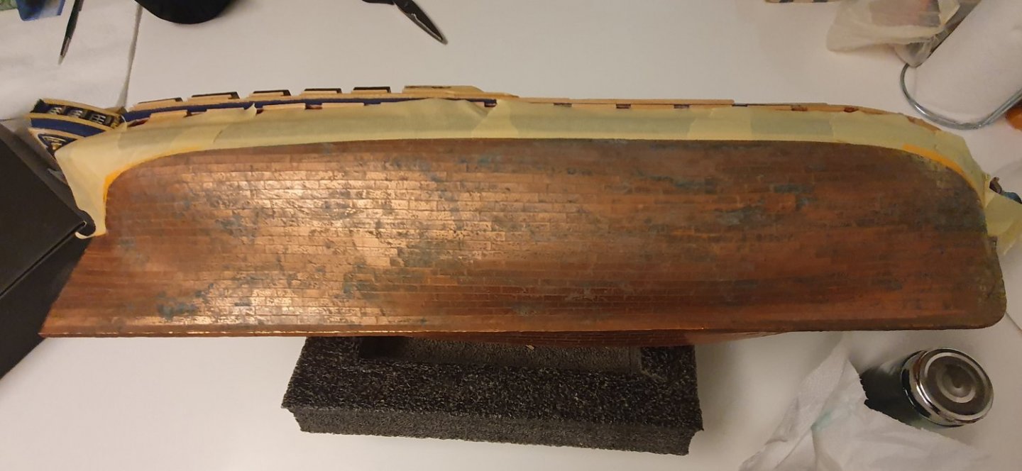
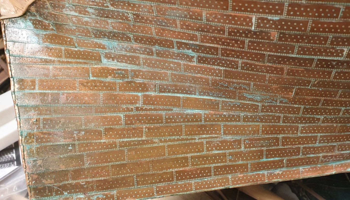
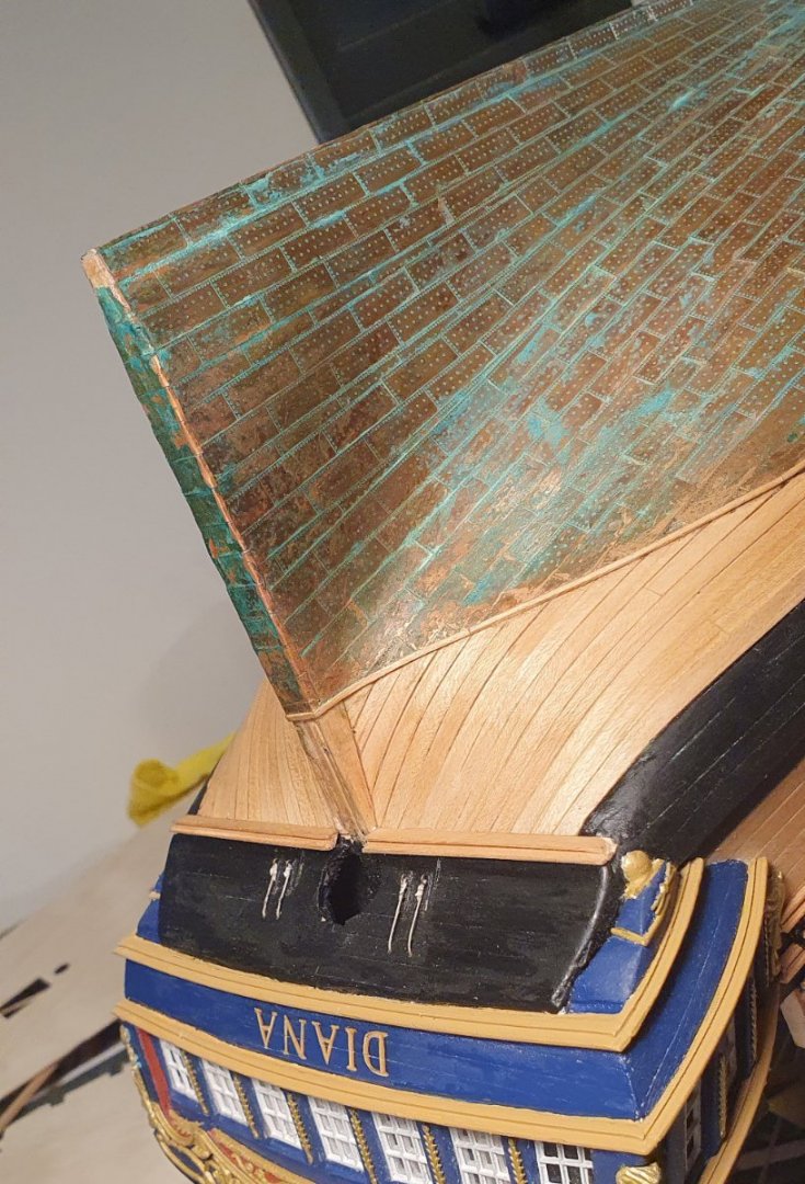
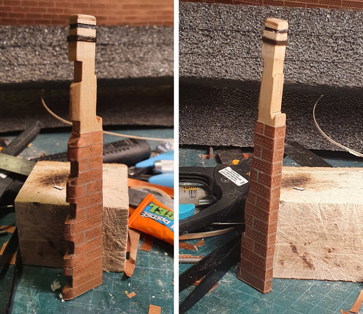
Time to tackle the copper bottom. My previous build had a copper bottom so I was hoping to learn for the missteps of that one. My Charles W Morgan came supplied with copper tape but I did not like the colour or finish so I made individual tiles from copper sheet which I marked up with a pounce wheel and then tried to add a patina but the end result was quite scruffy looking and way too green. The copper tiles supplied with this kit are fairly thick and have a very aggressive nail dimple. This tile is also missing the edge nails so I decided to keep those in the packet and look for some replacements. The best looking tiles I could find were the Amati 1:64 photoetch set. The tiles are handed for port and starboard. They are designed to be overlapped and contain no nail pattern on the top and side of each tile to facilitate this. I re-established the waterline with the laser level. I also had to add an additional 5x5mm strip of timber to the bottom of the keel as there was not enough depth to the existing one. I started fixing the tiles overlapping on the long and short side. The tiles on a real ship were generally classified into three gauges and the heaviest of these would be in the order of 1.1mm thick. This would represent 0.017mm at a scale of 1:64. The Amati tiles are around 0.095mm thick which is 5.5 times thicker than they should be. This additional thickness causes the overlap to produce seams that are much too pronounced. I decided I didn't like the look of them so I removed all of the tiles and started again with the tiles just butted against each other. It means that the nail pattern is slightly off but it is a less jarring solution. One of the advantages of doing it this way is that you can lay the tiles in strips of 4 straight from the sheet which makes the job progress a lot faster than individual tile placement. Having completed the coppering I wanted to apply some patina to the surface so I resorted to the standard solution of 1 part Miracle-Gro to 3 parts red wine vinegar. The red wine vinegar does not have to be organic, that was the only one they had in the supermarket. I wanted a fairly light patina but I guess I was distracted by something on the TV and I left it on a bit too long which meant there was too much patina from my liking. I was more successful with the rudder. This was the level of patina that I was trying for. I am not overly concerned about the finish as the copper sometimes takes on a life of its own and it may mellow out over time. Overall it is better in the Charles W Morgan but I think there is still a lot of room for improvement.


-
Thanks Jason. Learning CAD is not that difficult. It looks more complicated than it actually is. Once you have mastered a few basic commands you are good to go. I would rather have your carpentry skills. I am at a point in my model where I am doing the preparatory work for the installation of the upper decks and I was drooling over your recently completed work. Regards, David
-
Nice planking David. I am impressed you went down tapered plank route. Regards, David
- 310 replies
-
- 1
-
-
- Diana
- Caldercraft
- (and 1 more)
-
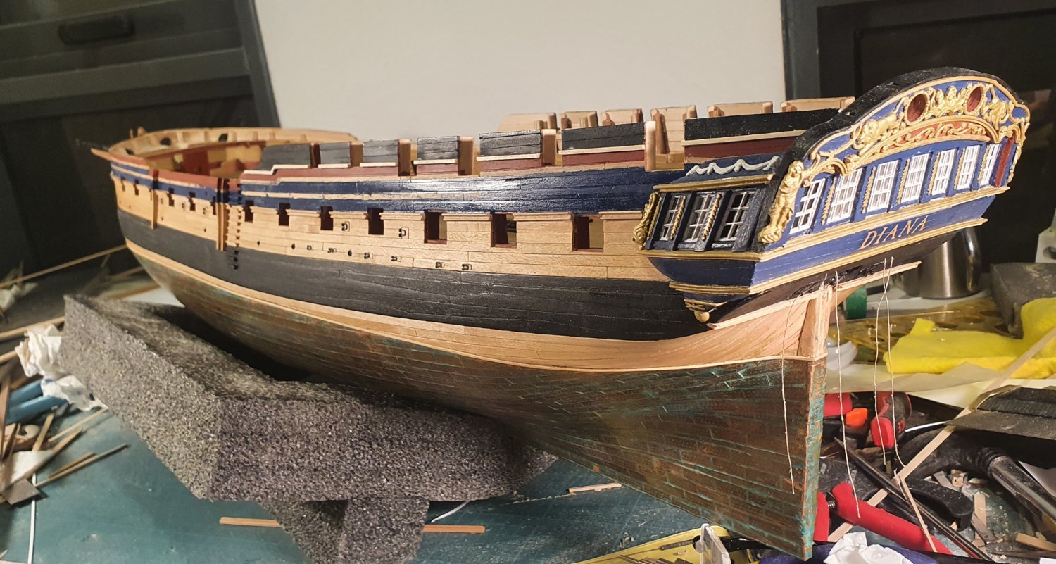
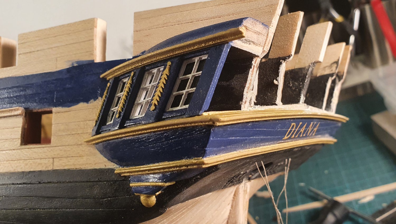
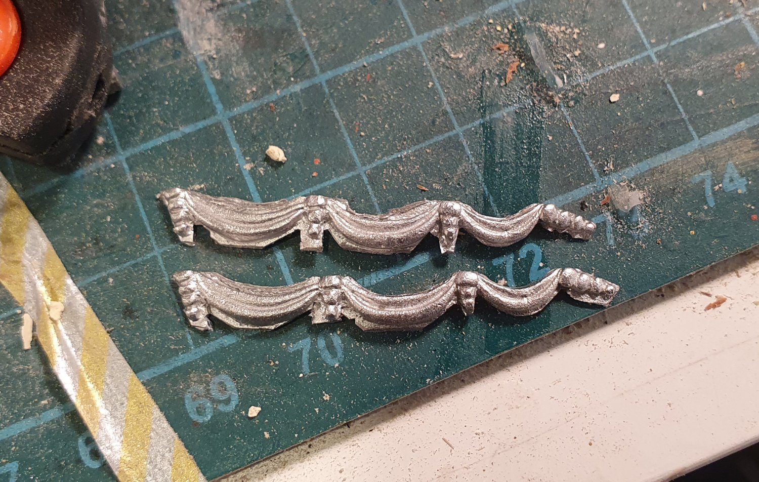
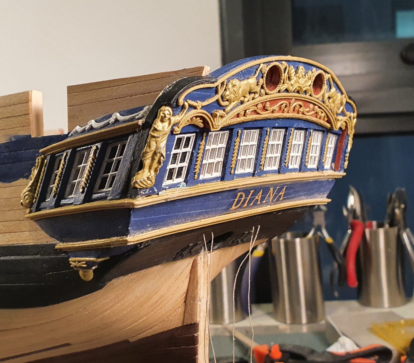
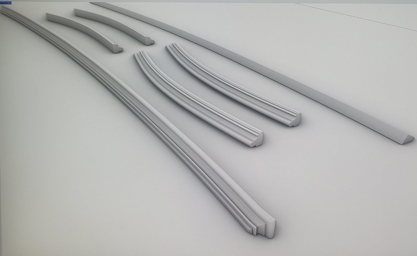
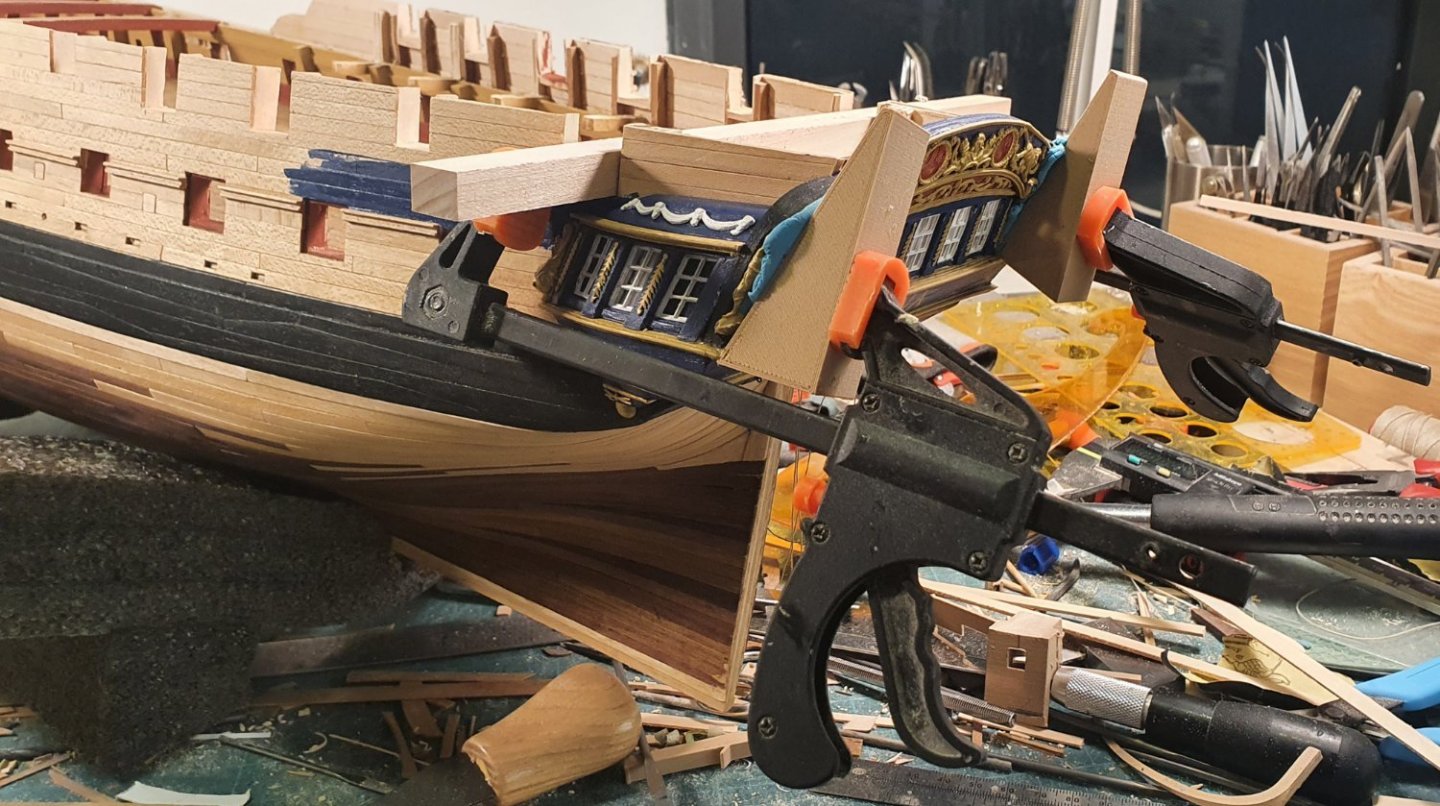
Back to the build. I started on the quarter galleries. I was not looking forward to this as I knew the result would be somewhat compromised. I started from the bottom up using the upper counter as my springing off point and utilising the kit supplied parts which I shaped using the dremel. I added some of the photo etch and cast decorative elements. When it came to the window section I found the kit supplied template gave an awkward geometry and the line of the window sills was off quite dramatically. I had to resort to the CAD again and drew up a replacement piece which I 3d printed. This was then clad with walnut to form the pilasters ready to receive the windows. Having already established the geometry in the CAD program it was relatively easy to model the window frames. Two false windows and one vision panel. These were 3d printed, glazed then glued in place. I 3d printed the various mouldings for the galleries. I have now got my hands on a scraper tool that has some good profiles. Once I obtain some boxwood I will theoretically be able to fashion those out of timber which I think would look better. I was dutifully trimming the excess material from the kit supplied decorative swags until I realised that I had been given two starboard pieces. I had to resort to the CAD and 3D printed route again which was disappointing as the results are lacking the definition of the cast parts. I added the other decorative elements and constructed the top rail. Time to attach the rear fascia. Because I had laminated on so many layers to build this up it was a lot less flexible than I had anticipated. I needed to construct some temporary works to try and hold the curve while the glue set. I also added another couple of inboard upstands to allow for more contact area for the glue. I still imagine that one day it will eventually let go with a loud twang sound. I added a veneer of planks to the inboard side and that is the major portion of the stern with quarterdeck galleries complete. The whole assembly sits too high. I wish I could just grab it and slide it down 4 or 5mm.


-
Hi Ian, if I was going to paint them then 3D printing would be a possibility but I was aiming to have them in a natural wood finish. Regards, David
-
Thanks David, I guess you are all too familiar with the shenanigans you have to go through to get that thing built. Regards, David
-
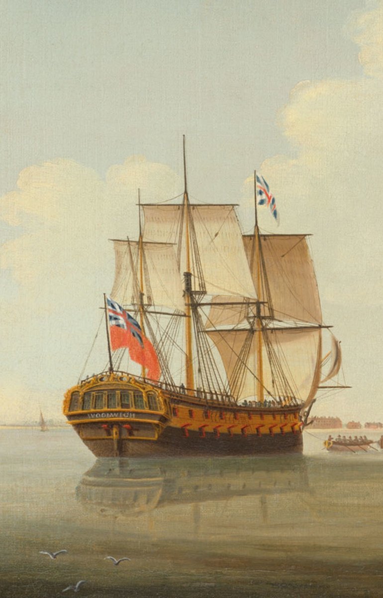
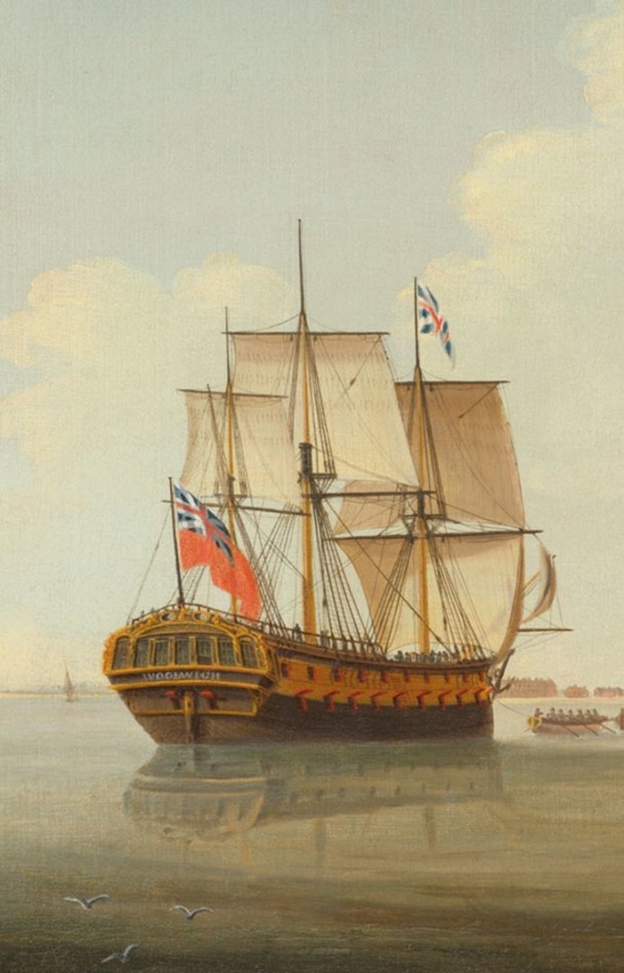
I knew I should not have replied to the subject as this will no doubt turn into an endless discussion on the naming of ships however I just did a bit of digging around and found numerous examples of names on ships after 1780. I assume that it was either not strictly enforced or was repealed at some point. Here is an extract from a contemporary painting depicting HMS Woolwich launched in 1784. The painting is dated 1795 with the name clearly visible on the stern.
-
I believe that in reality the painting of names on ships after 1771 was more nuanced than your bold statement would indicate. I am keeping mine. David
-
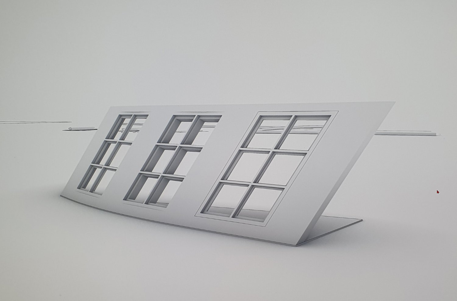
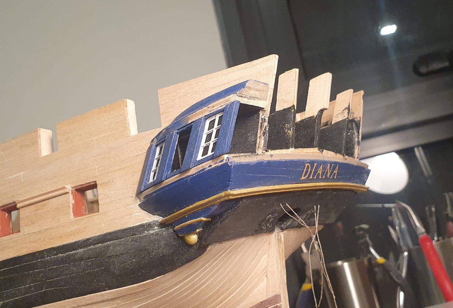
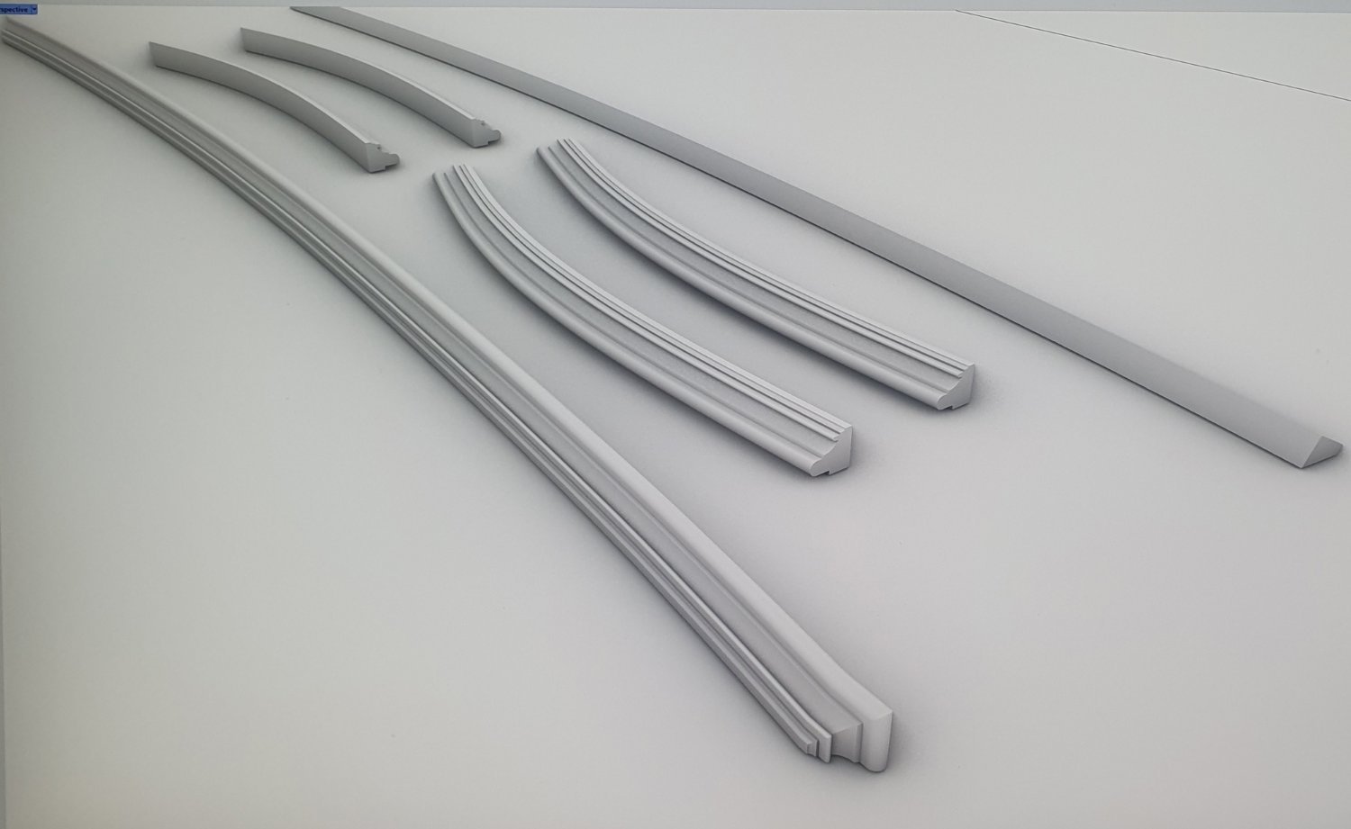
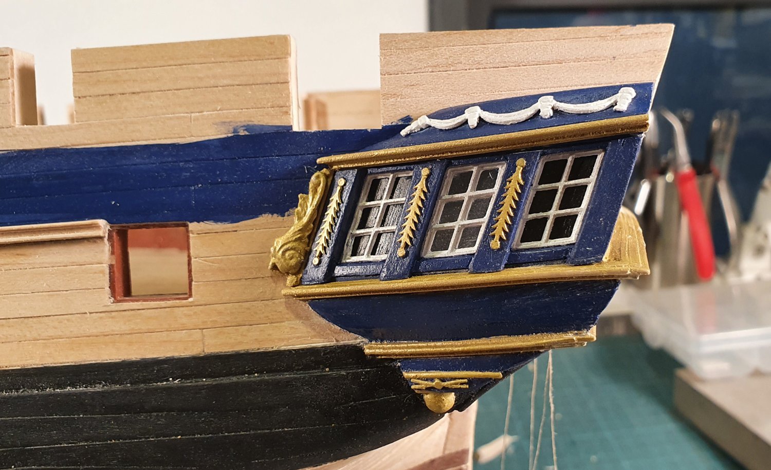
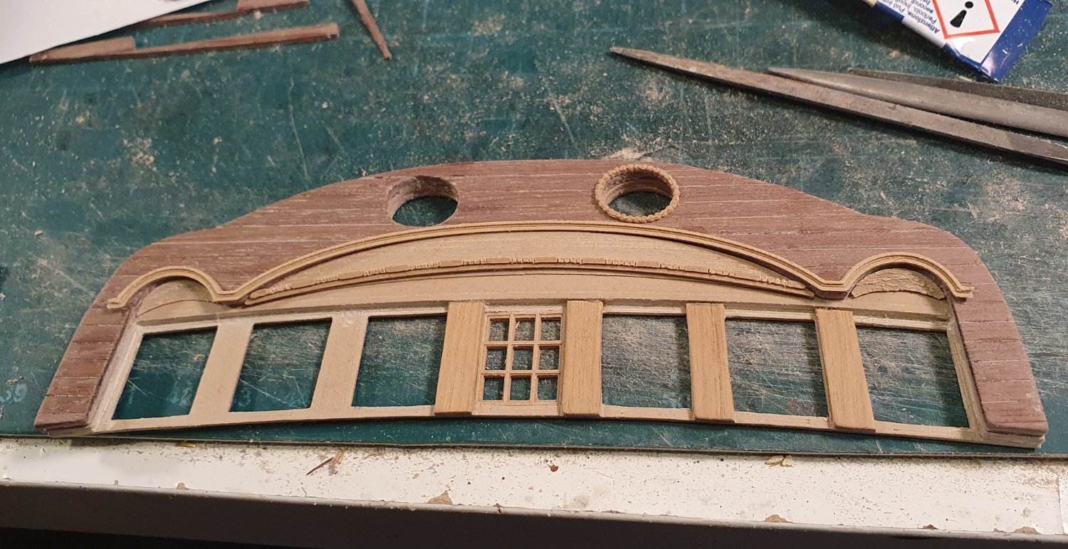
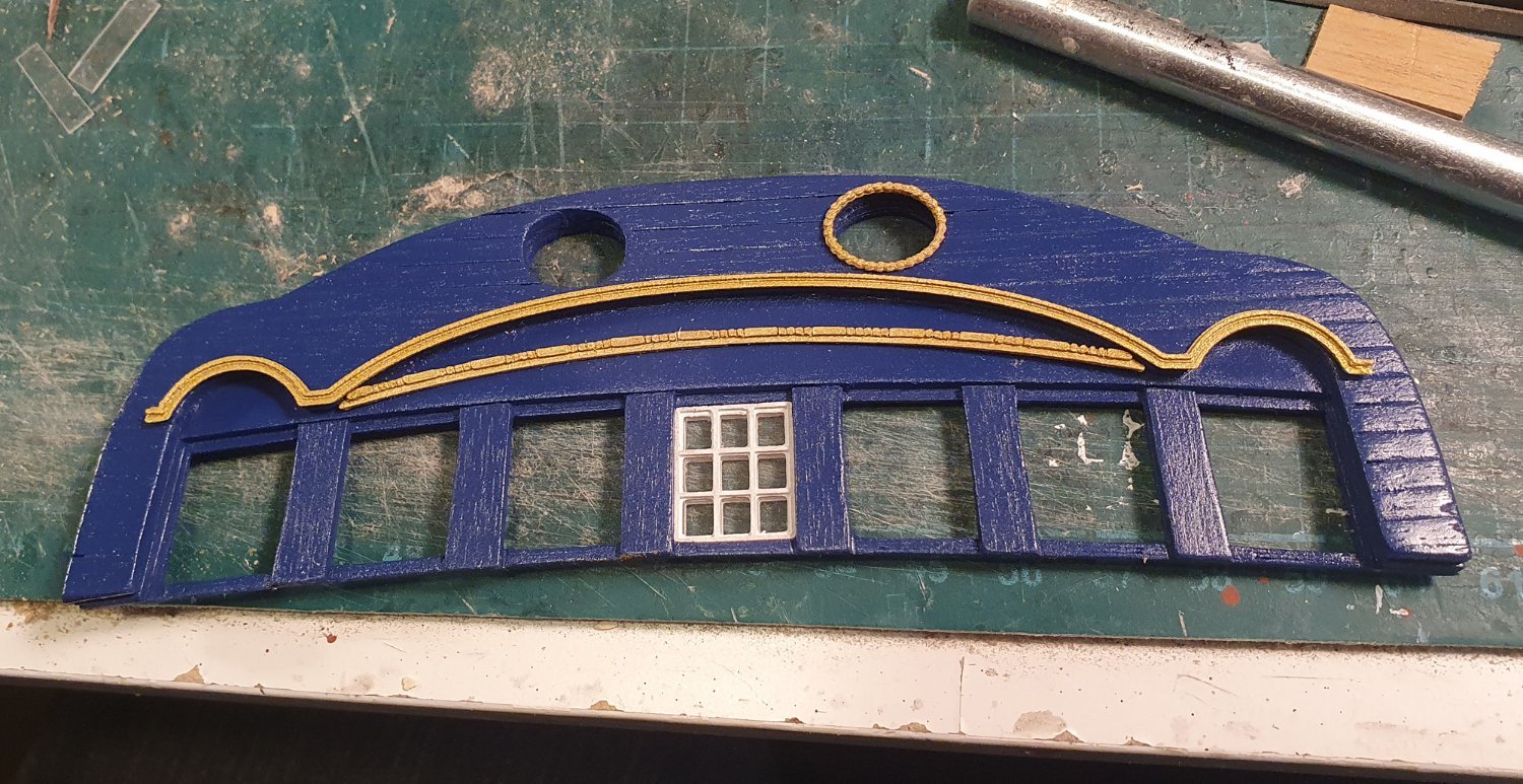
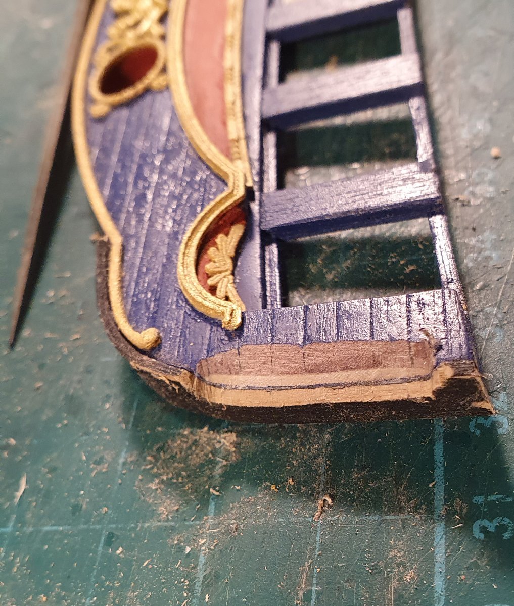
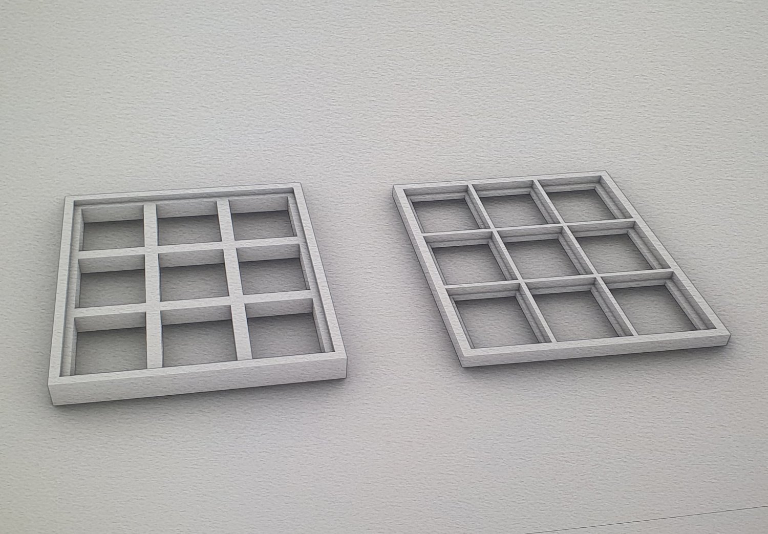
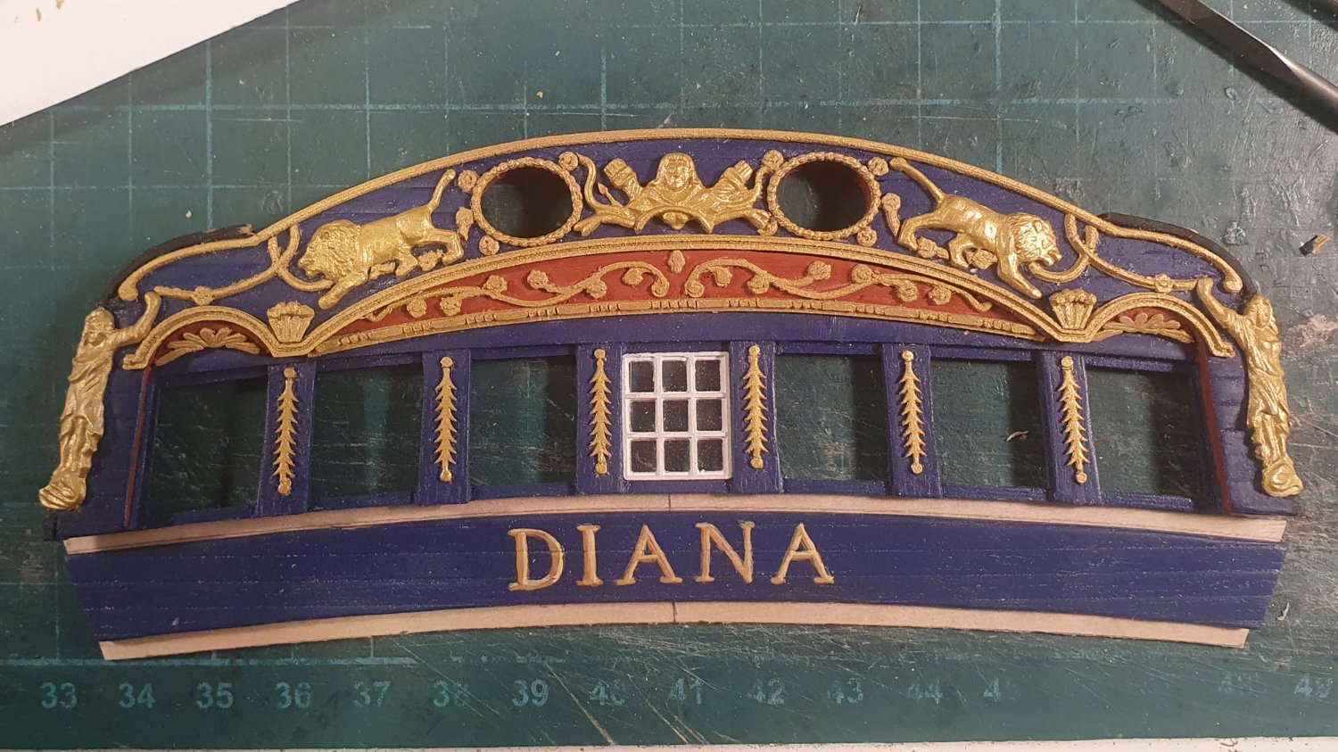
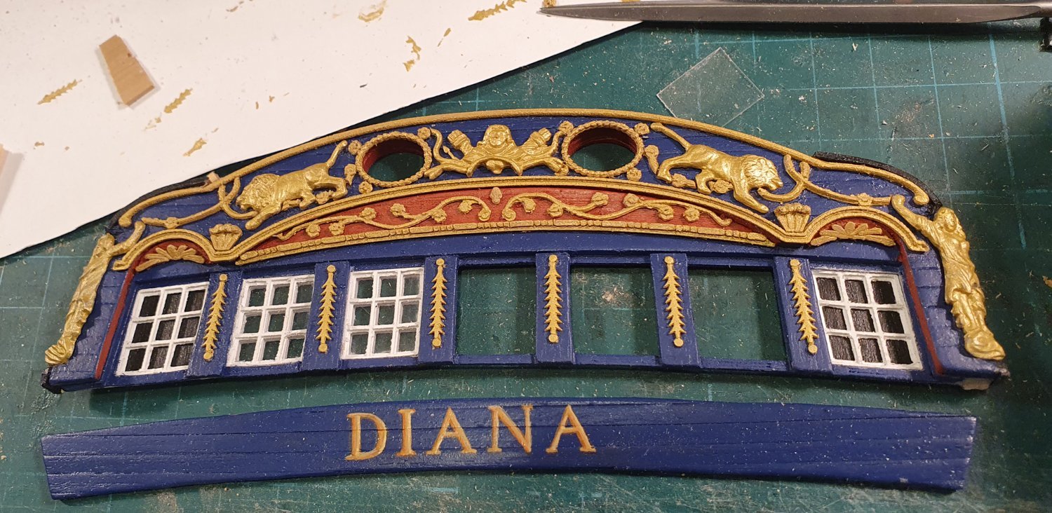
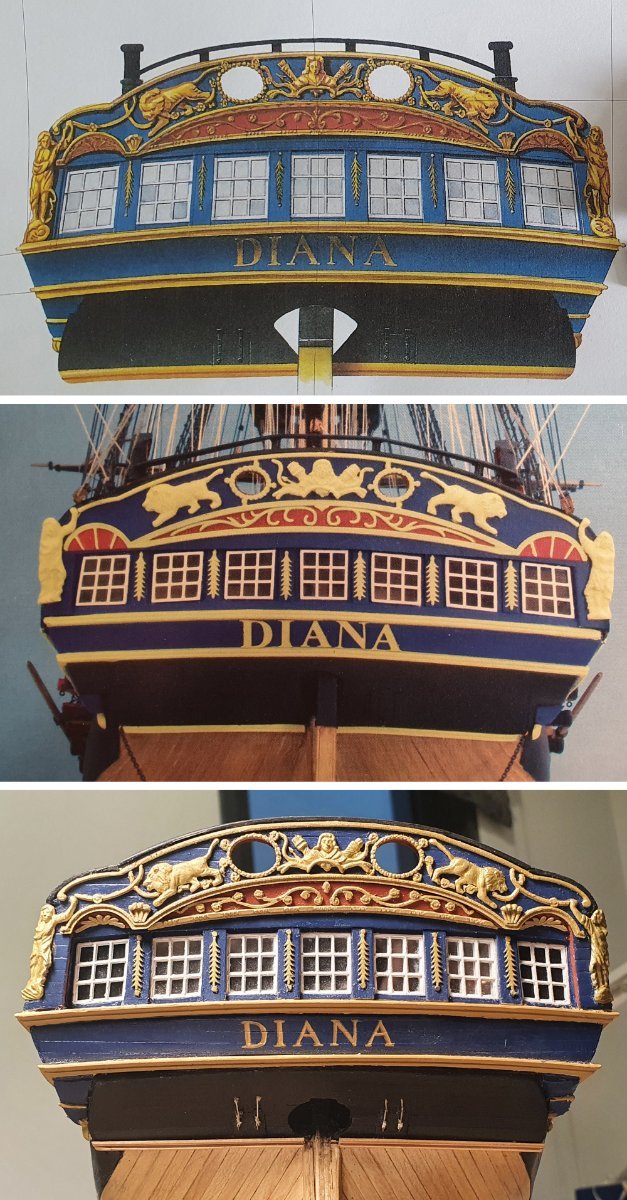
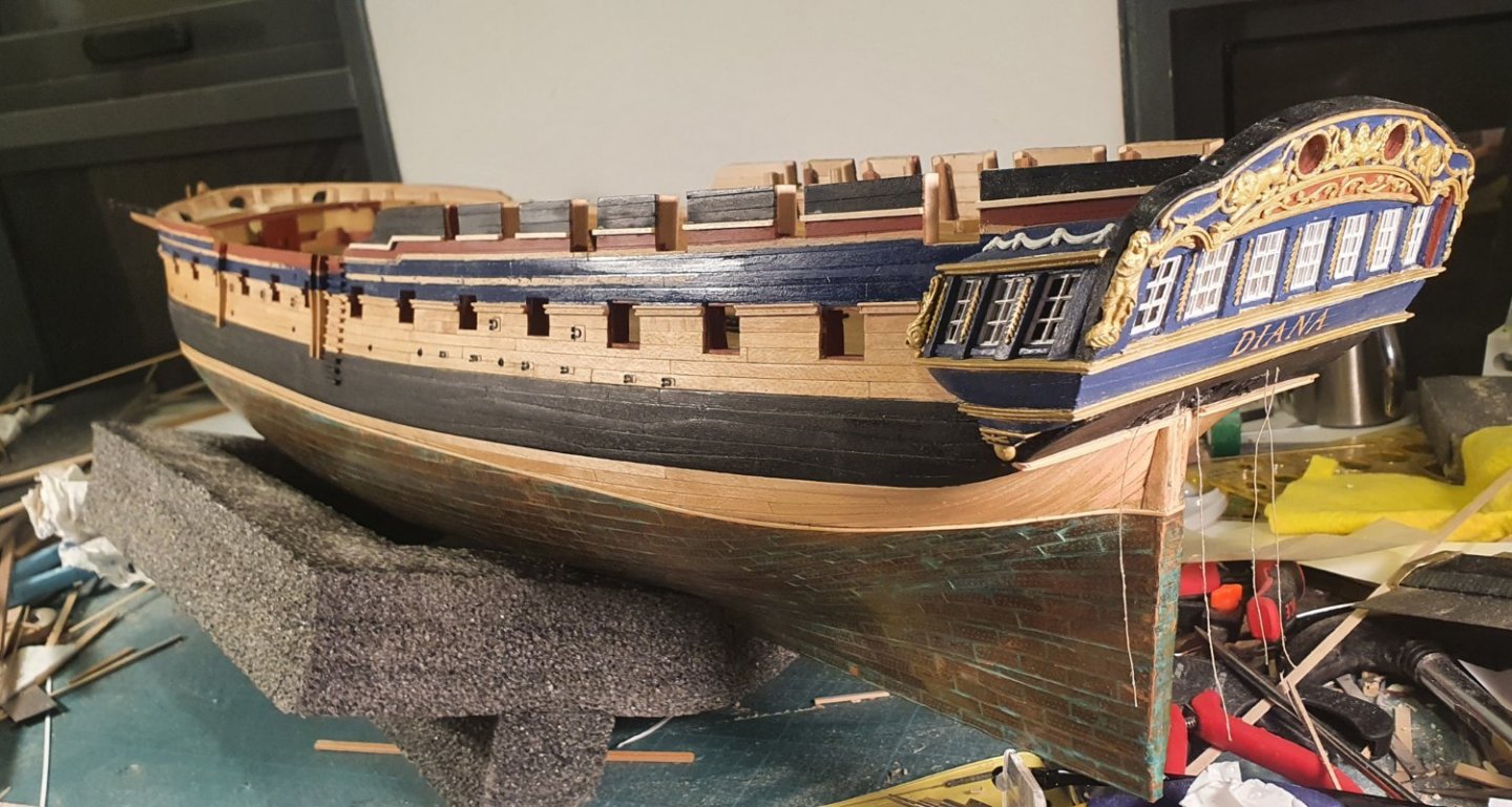
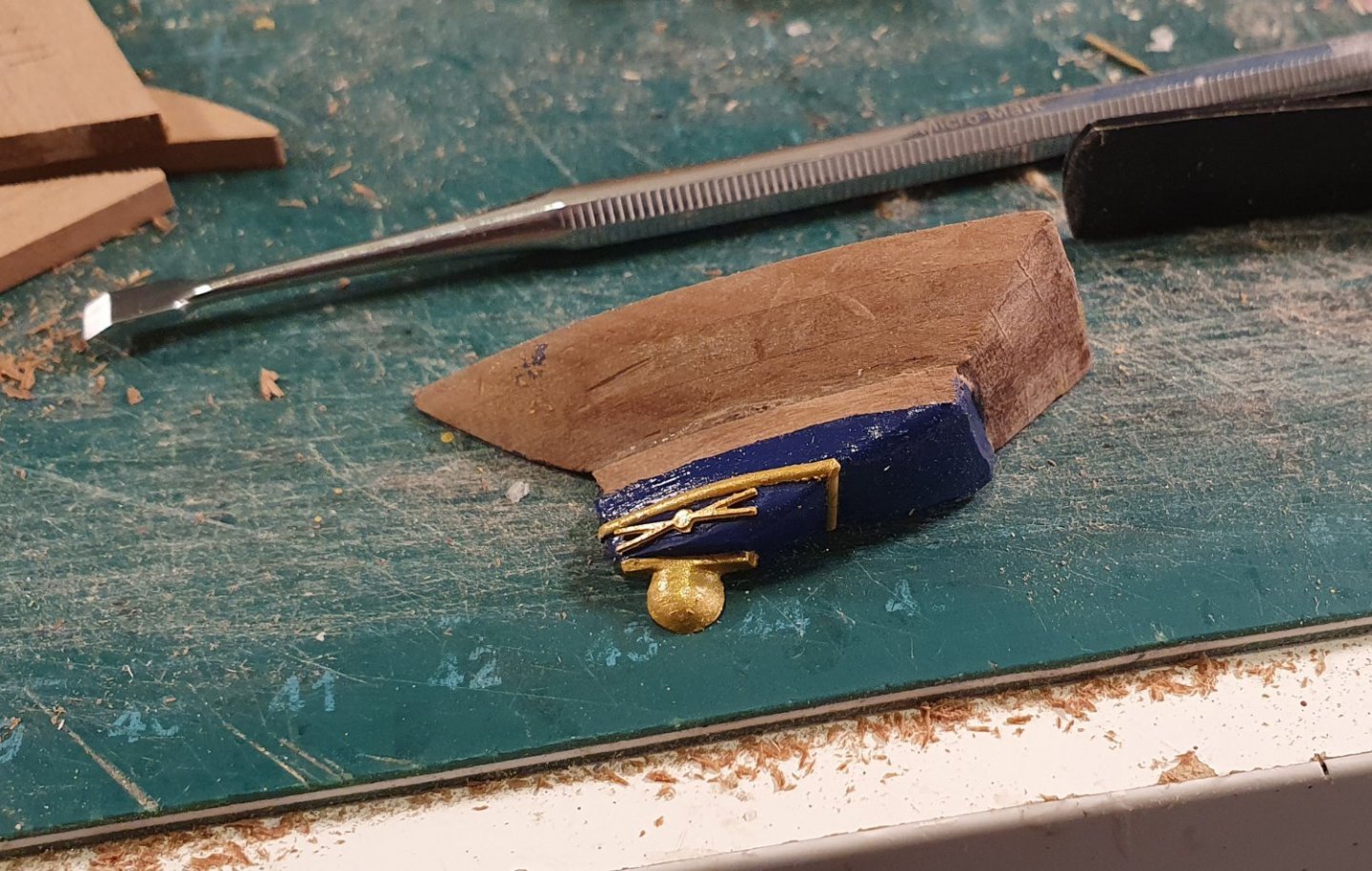
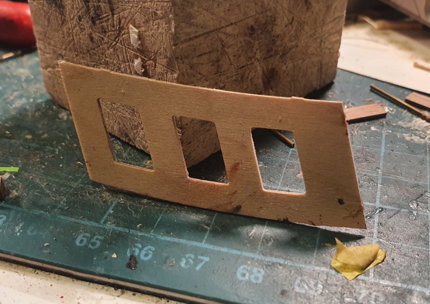
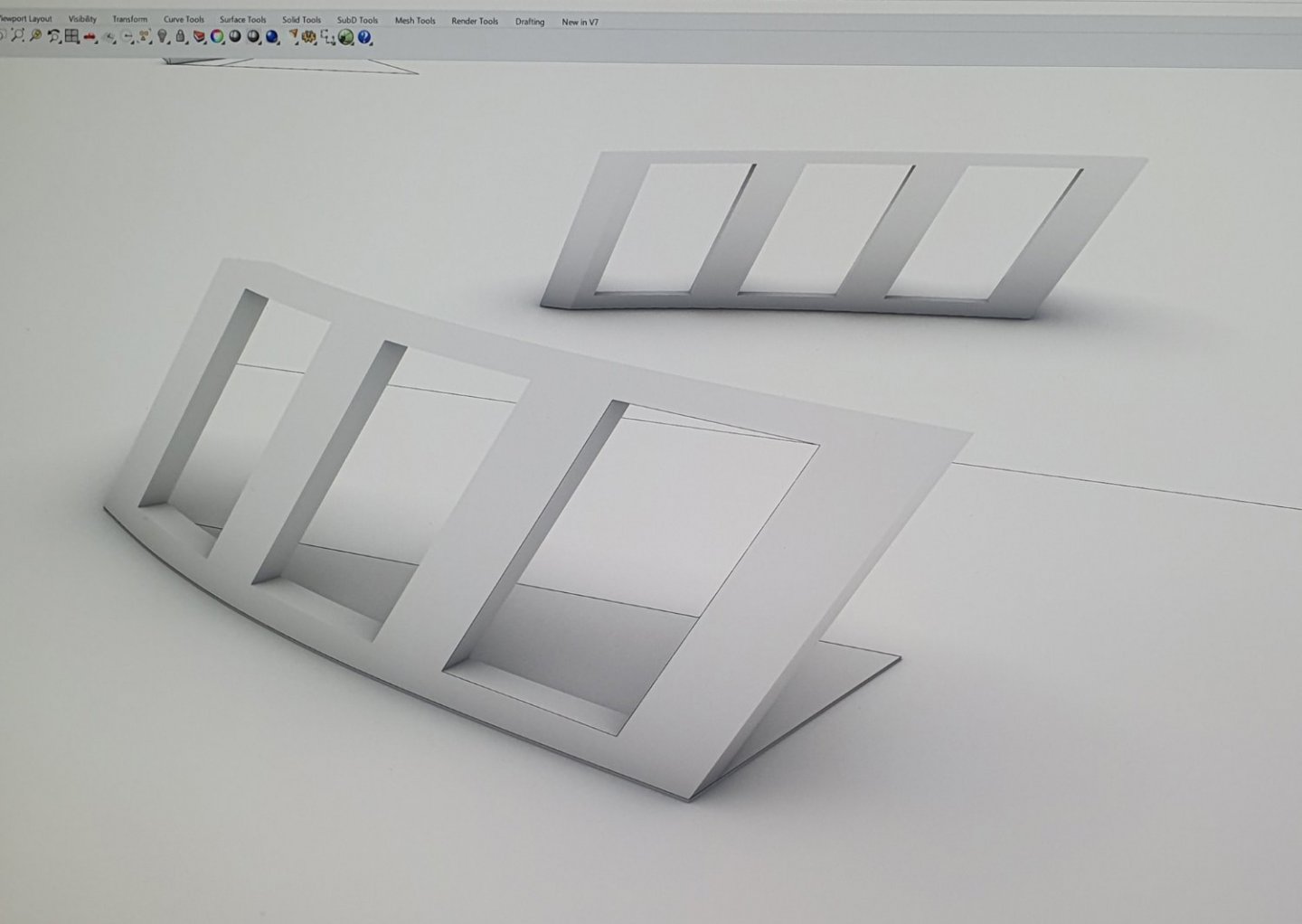
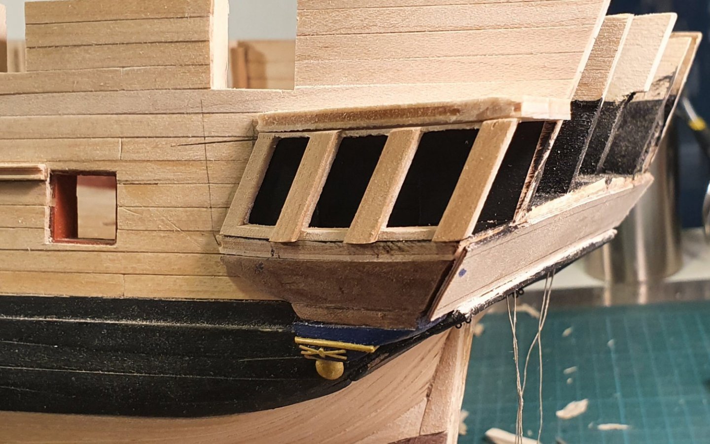
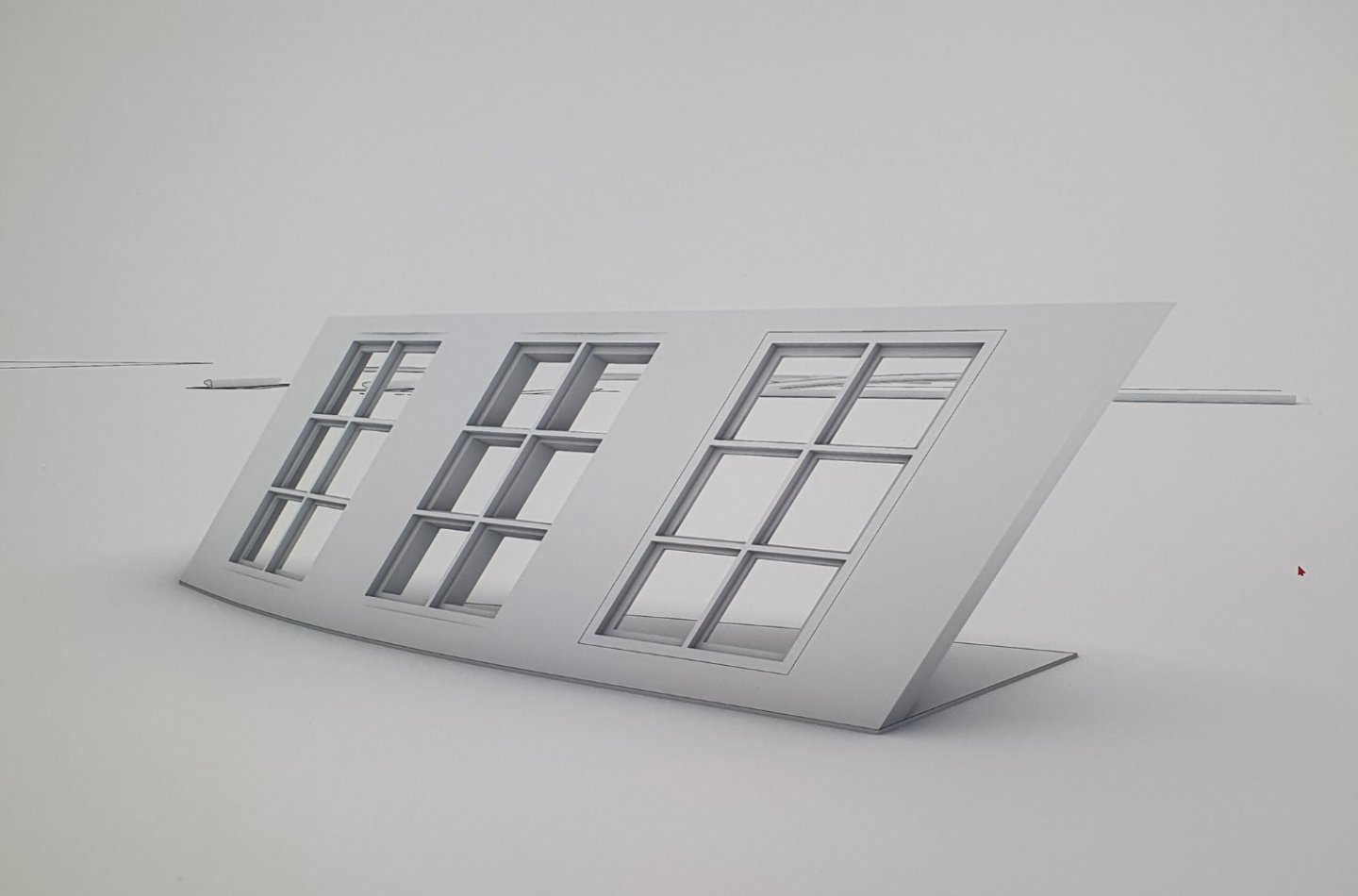
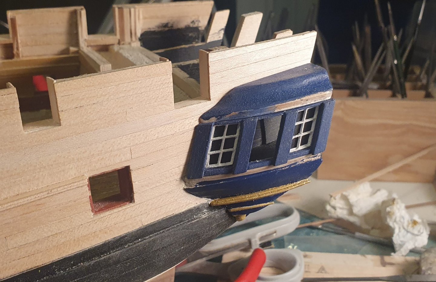
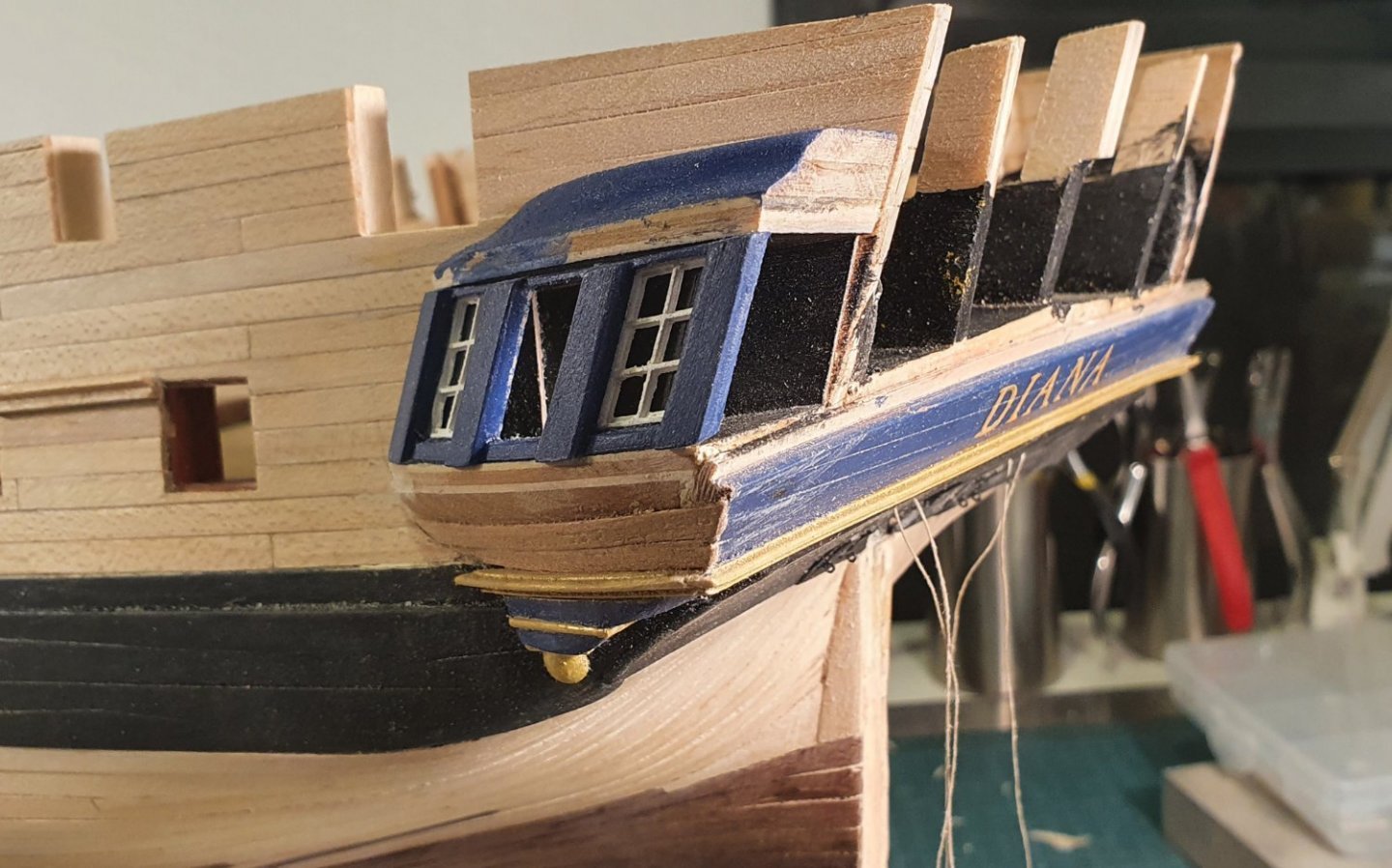
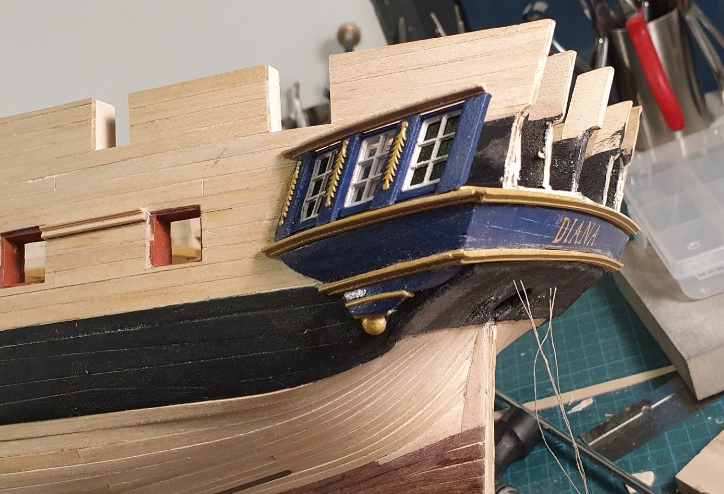
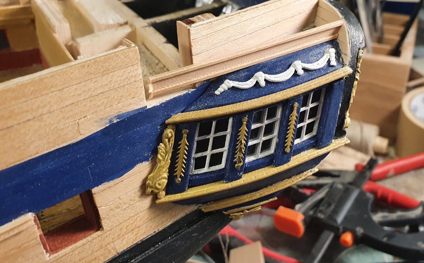
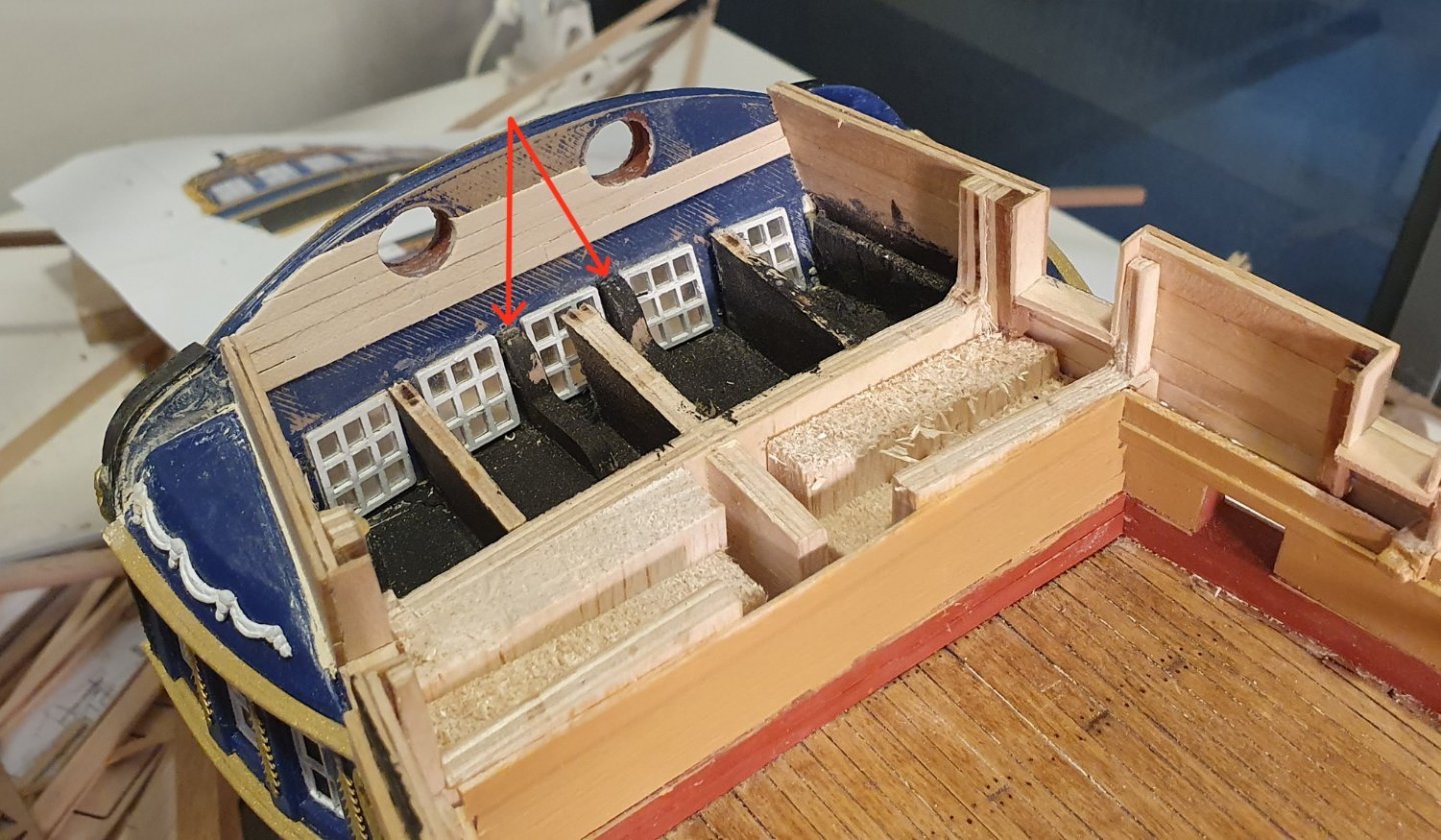
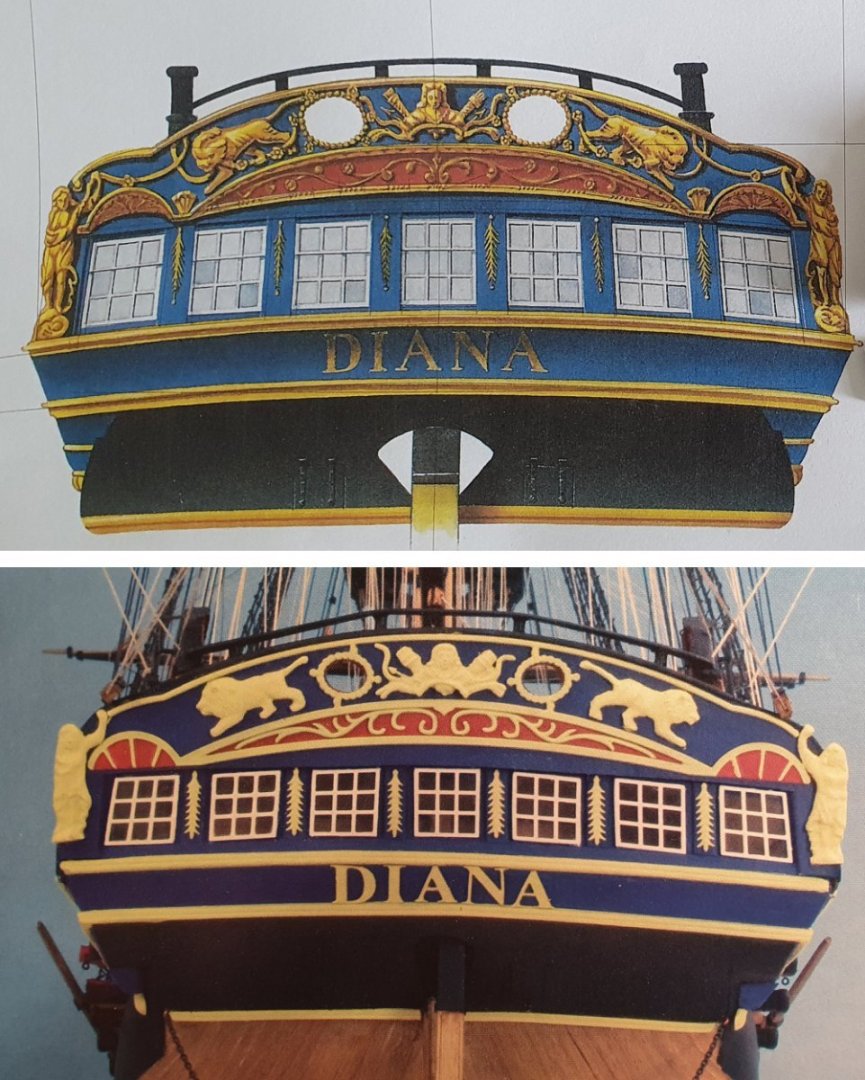
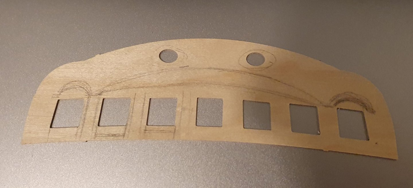
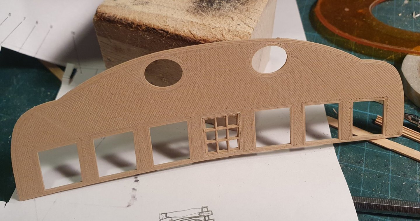
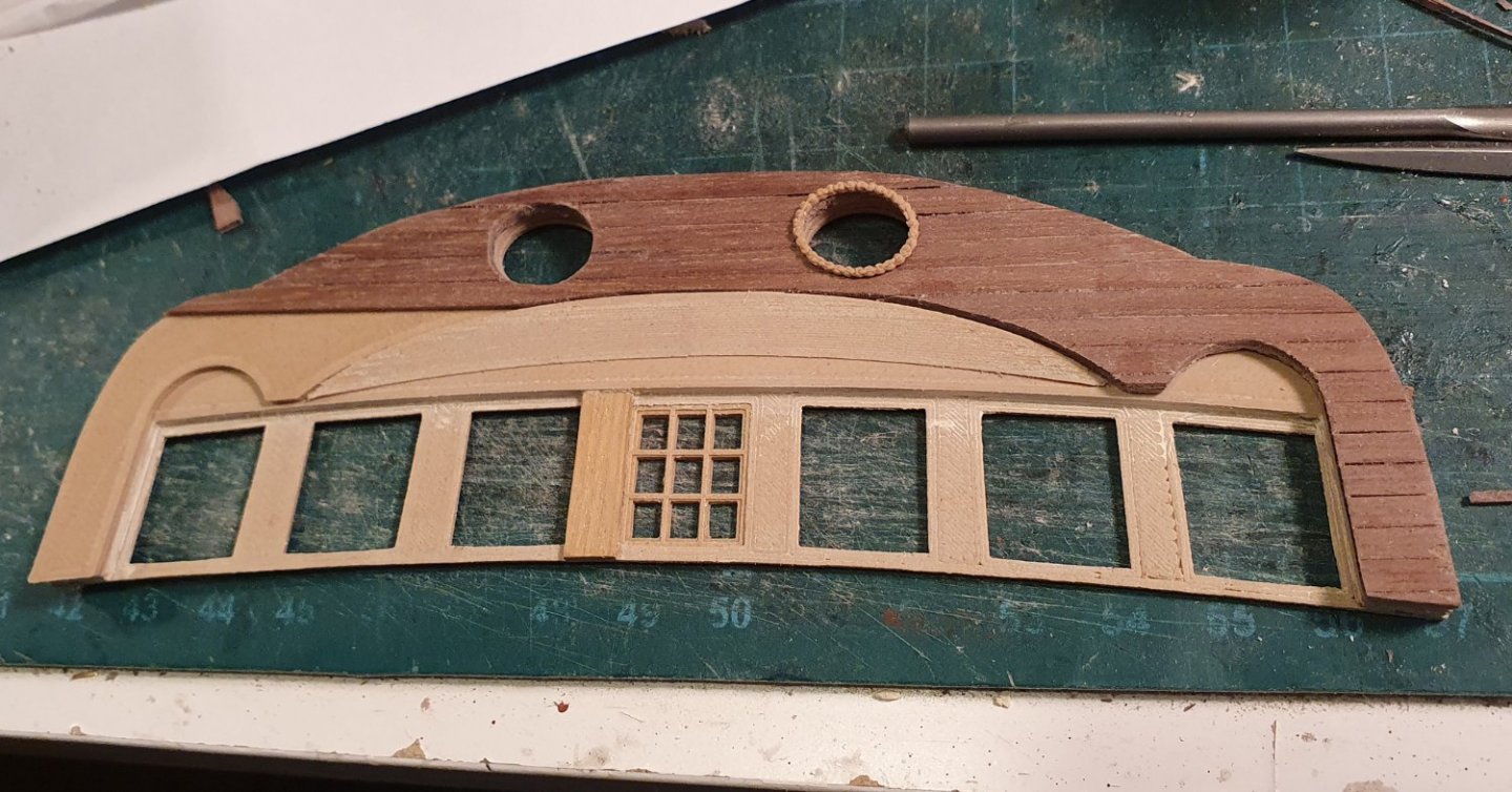
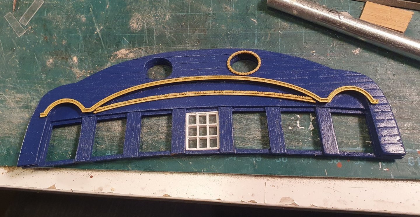
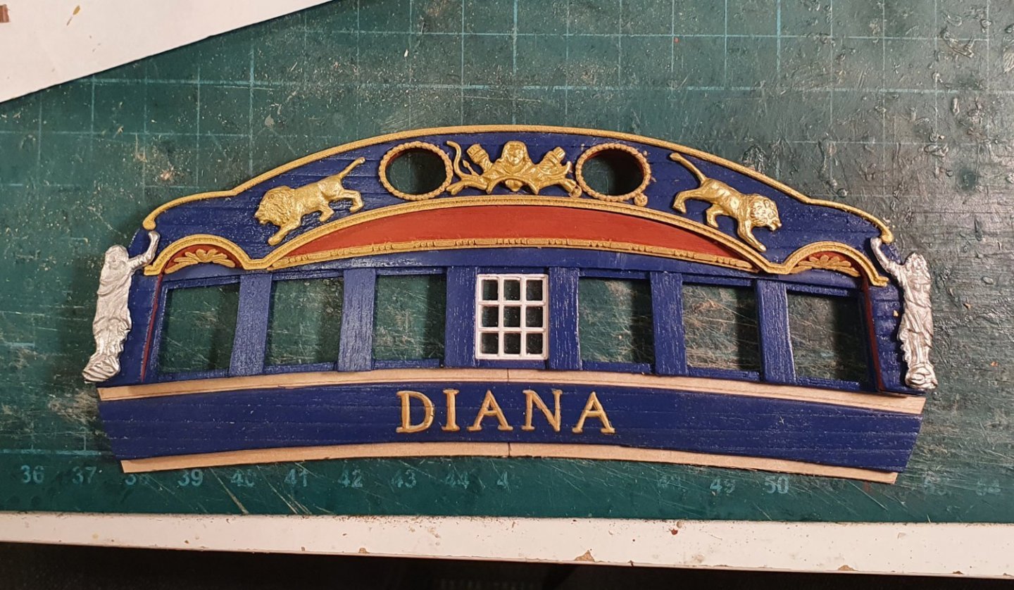
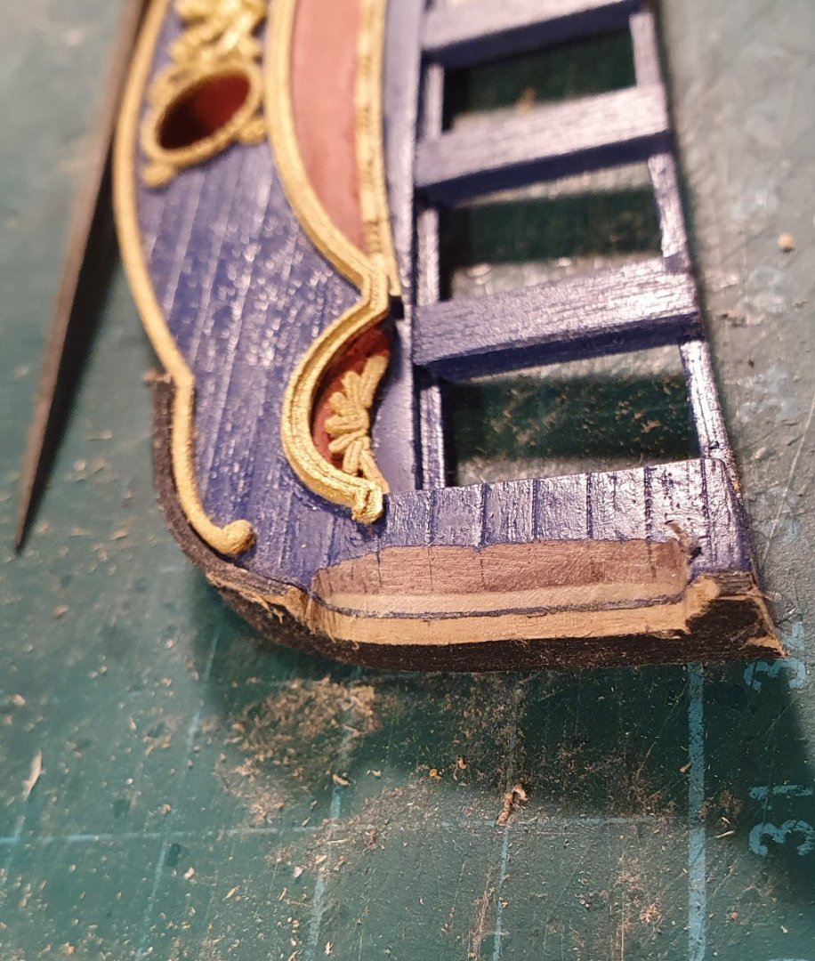
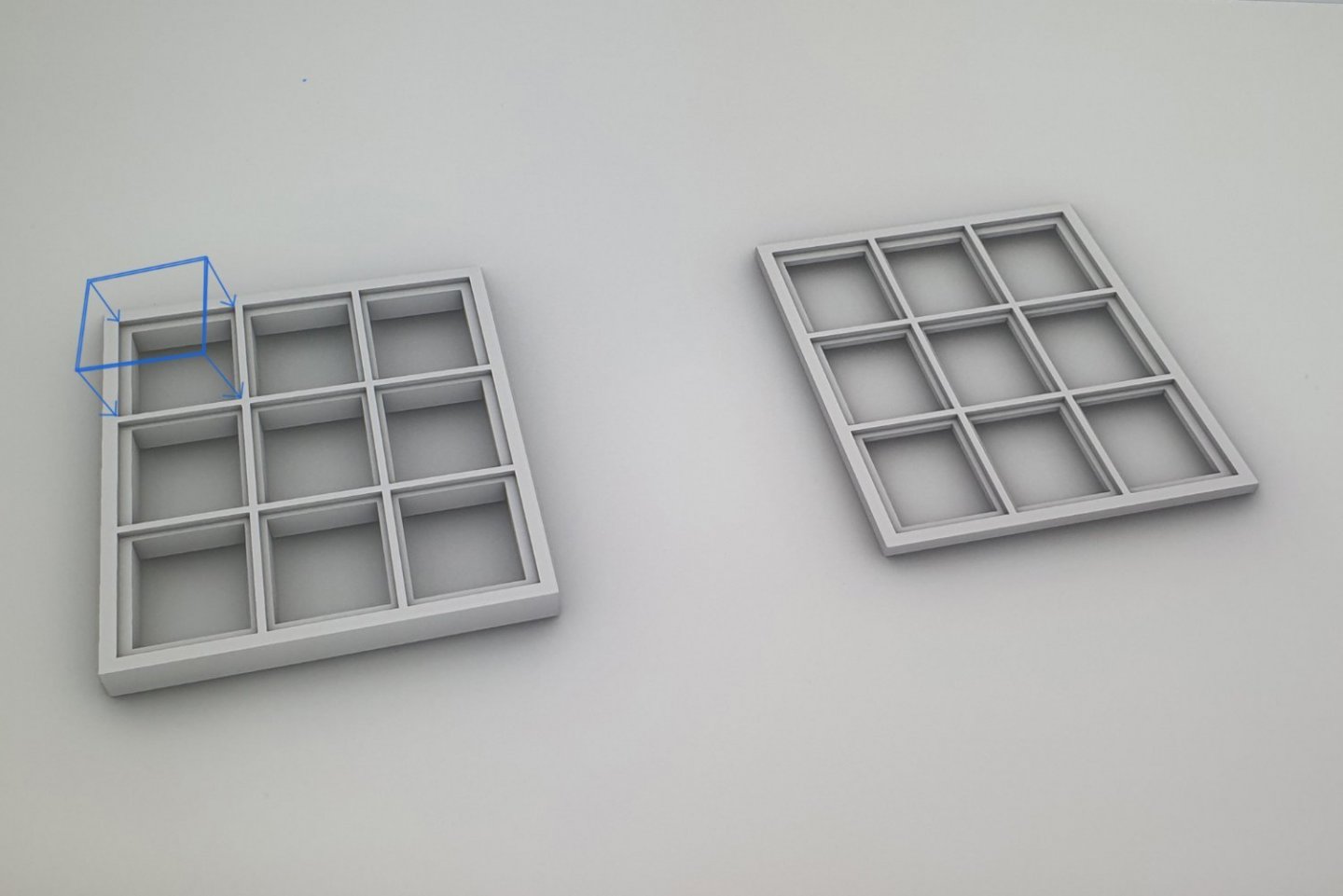
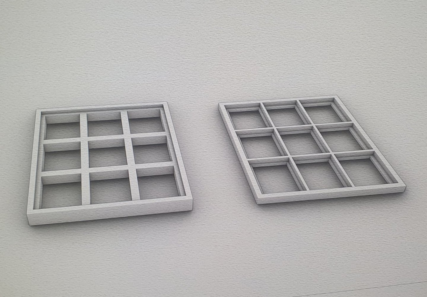
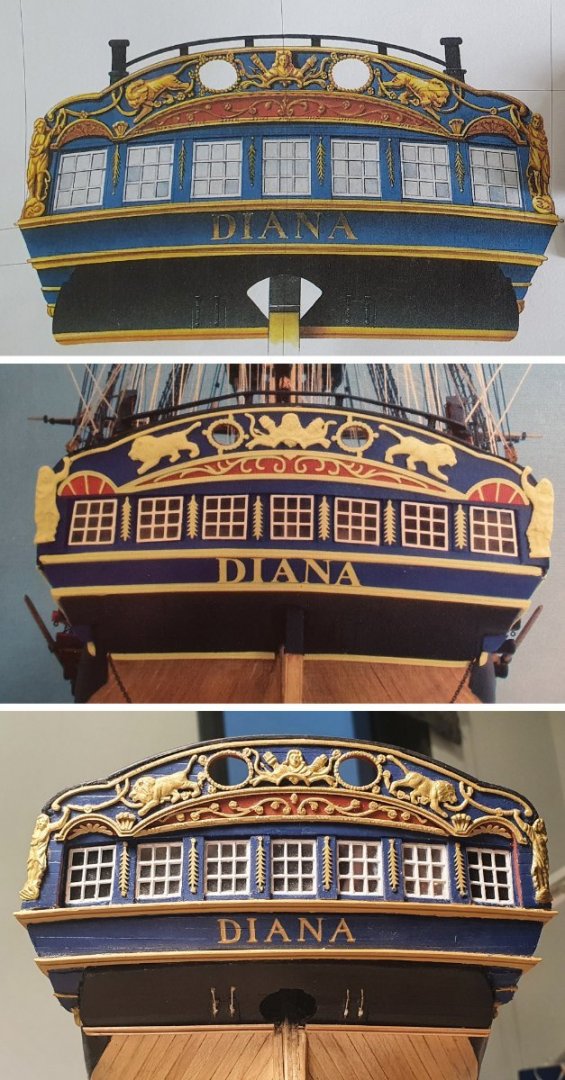
I started the rear elevation by comparing the AOTSD rendered drawing with the photo on kit box. You can tell that the kit version has used the AOTSD drawings to base their design on but there seems to have been some value engineering on the go. The kit version has lost some of the depth. The windows appear to be a different proportion and are a bit too square. The springing point of the side arches over the spandrel windows look like they have been shifted over and the decorative elements has been simplified and watered down. I had a look at the ply template supplied and decided that it needed too much surgery and wasn't worth saving. I drew up an alternative on the computer and then 3D printed a new template. I then started to form the various steps and pilasters using walnut planks. I 3D printed some of the mouldings and decorative pieces as they were too delicate to be made out of any of the woods that I had to hand. The 3D printed parts are a bit ropey but they are the best that I can produce using the Fused Filament Fabrication (FFF) technology printer that I have. I should really invest in a Digital Light Processing (DLP) printer to improve the resolution. I painted everything with the garish blue and the decorative elements in gold. The gold was a big mistake. I should have rather used real gold leaf or yellow ochre instead. I repainted some of the mouldings in yellow ochre but the I don't want to risk repainting all of the decorations. I built up the upper counter using walnut planks. I really should have curved these but for some reason I didn’t. I did not like the look of the photoetch brass letters supplied so I thought that I would try my hand at painting the name which seems to be what happened in practice. It came out a bit shaky but if you look at it from a distance and squint your eyes it is acceptable. I took the dremel to the corners to provide a recess to accept the figures. For the windows I also went down the 3d printed route. I notice a lot of the windows offered in kits consist of a set of photoetch mullions where they encourage you to stick some acetate on the back of and then glue on the model. In order to simulate a real window they should supply two sets of frames, one thicker than the other, which you can then use to sandwich the acetate. My initial grand idea was to provide a sub-frame where I could place each individual pane of glass cut from acetate or glass from a slide cover. The plan was that the slight variations in placement would have caused a realistic window effect as the light reflected off them. I managed to cut out one pane and then had to lie down for a while to recover so I gave up on that idea. It probably would have been feasible at a scale of 1:48. I reworked the sub-frame so that I could install the acetate in one piece. This is the fascia mounted on the model compared to the two references. It looks like a marginal gain on the kit version but I am still not happy with the decorative elements. I would like to replace the figures but sourcing them is problematic. I may go and rummage through some Toy/Hobby shops to see if any of them have a range of small plastic maidens striking heroic poses.


-
Hi Allan, Yve's use of the copper tape is impressive but I am afraid the die has already been cast in terms of my copper bottom. I have already completed the copper work and I will cover this in a couple of posts time. Regards, David
-
Hi David, Thanks for the links regarding the boxwood. I will definitely check them out. I am finding your build log very useful. In terms of progress I have always been a little bit behind you which is to my benefit as I always get a tutorial about the next part of the build I am about to tackle. Regards, David