HOLIDAY DONATION DRIVE - SUPPORT MSW - DO YOUR PART TO KEEP THIS GREAT FORUM GOING! (Only 13 donations so far - C'mon guys!)
×


Kranck
-
Posts
69 -
Joined
-
Last visited
Content Type
Profiles
Forums
Gallery
Events
Everything posted by Kranck
-
Thank you for your answer ! Yes , his Le Gros Ventre is a fantastic build. i am also amazed by what Oliver manages to do with a manual milling machine on his La Belle and Le Redoutable. thanks for the tips. I will give La Belle some rest now and think some more. Meanwhile, i came back to my former build, the smaller Le Cerf. No CNC there, and no admiralty build... much easier ans satisfying !
-
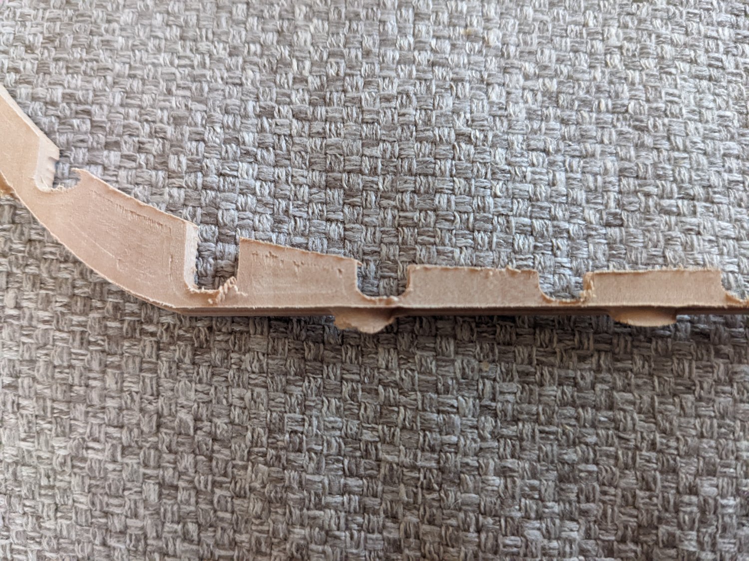
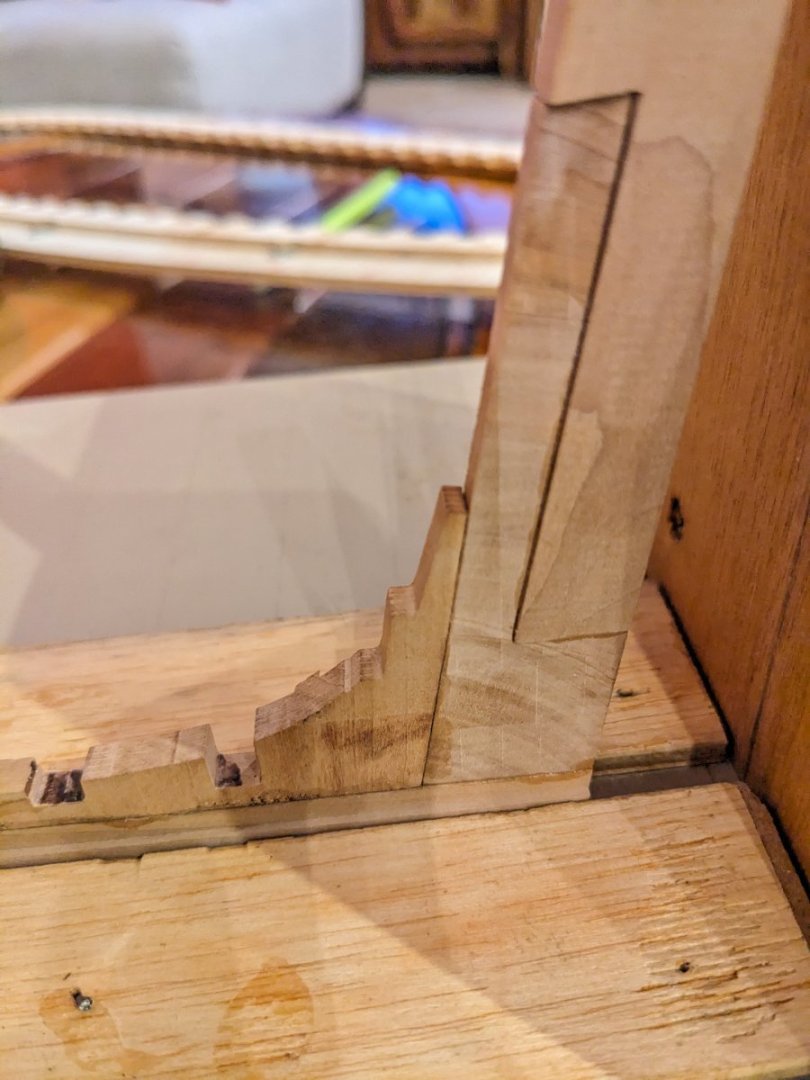
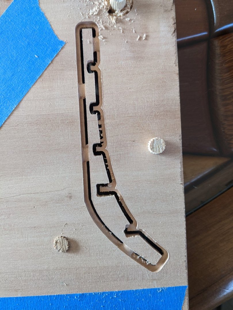
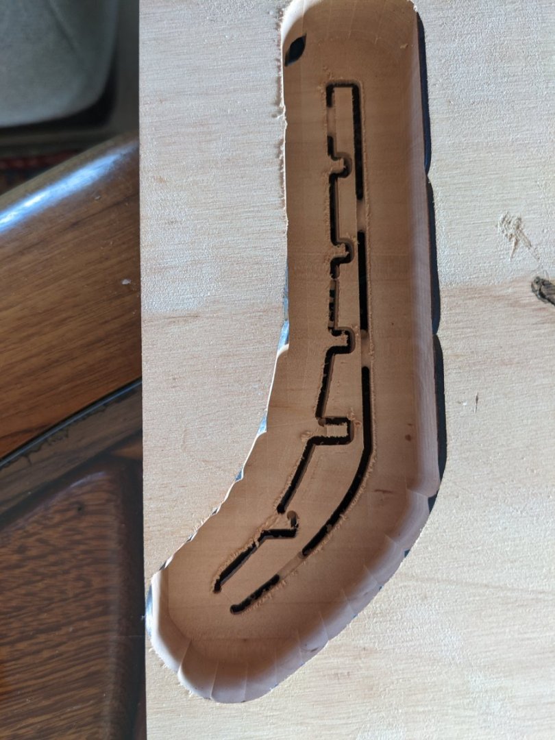
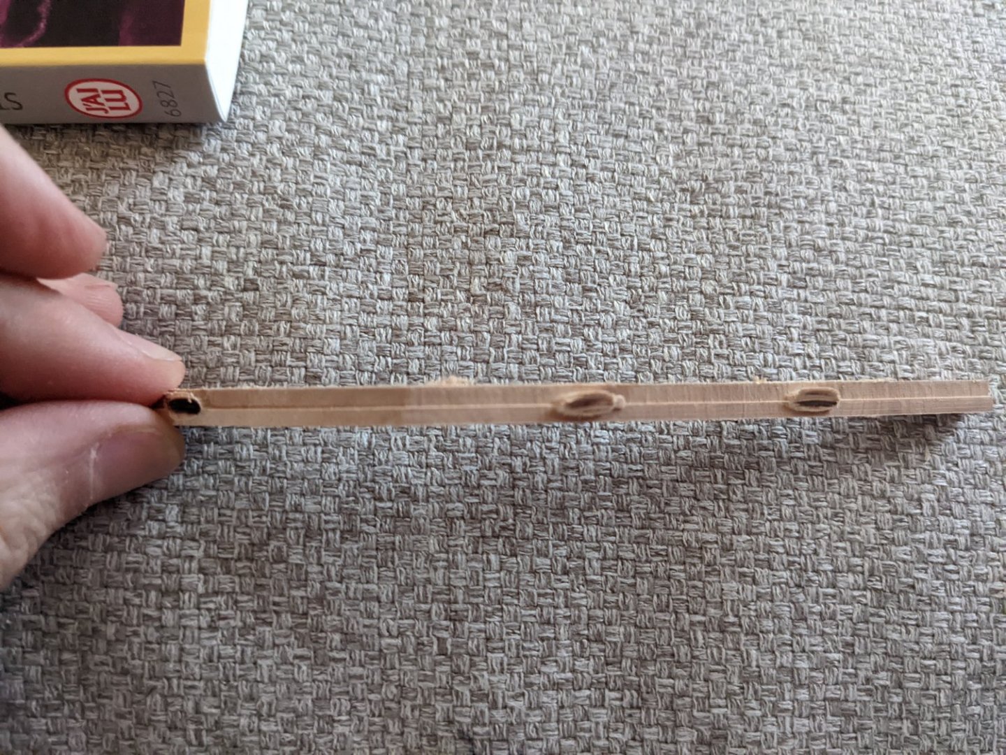
So, after a few months on and off the hobby, I just wantd to update on the project. * CAD drawing was satisfyingly accurate. I stopped at some point to start getting some real parts for this ship. * Getting accurate 2D or 2.5 parts is rather easy with one sided machining on the shapeoko 4. It took just a few days to get a .2 mm accuracy, which is sufficient for our purpose. * Getting 3D parts with two sided machining is an entirely different matter: Consider for instance a frame or a part of a queel with a rabbet on each side. The two main issues with two sided machining are getting an accurate thickness when turning the part, and be able to accurately zero X and Y. But the nightmare starts way before that: first, you have to choose a CAM soft to be able to transfer your part into a series of G-code instruction. To whom it may concern: most pieces of software available for hobby are NOT accurate enough. Only engineering-grade soft are good enough. For instance, Aspire, from VECTRIC, does not handle properly 3D parts (an issue with voxel size). Other just can't handle 2 sided machining properly. I ended up using fusion 360. But first, it is therefore necessary to transform the rhino files into fusion 360 readable files. You don't want to know, but it is not an easy tasks (many restriction for the free version of fusion 360). Since even in fusion 360 there is not 'intuitive' way to prepare your files for 2 sided machining, It does take a lot of time foreach file to do so. And an error in one single step will wreck your piece on the machining table. Then you have to deal with all the diffficulties of preparing appropriate dowels, double sided tape, and be extra careful for each manipulation of the part while machining. Of Note: the more you machine your stock, the less wood is left for rigidity. It WILL start to bend. Well, as you can infer, I finf this step extra difficult. I increased my knowledge of the process and I got better and faster. I do enjoy the accuracy of the curves, but with such tools, it is wrong to think that all parts will magically fit perfectly. Sanding is indeed required. I just wanted to show the queel and the first half-frame. I do wonder how people can get parts to so nicely and tightly fit. Is it necessary to finish machining with a manual milling machine? I also wondered how do hobbyists highlight the edge of the parts with a black line? I think caulking shouldn't be visible at this scale, but the effect is nice. Anyway, my main difficulty is that I have no bakcgroung in manual machining of wood. I hoped to compensate with CAD and CAM but it's hard. Any good books on the woodworking tehcninque itself as requied by the hobby? Best regards, Nicolas
-
Here is the wood. Next one will be better hopefully

-
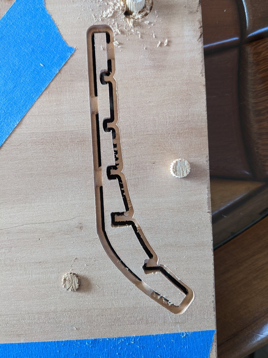
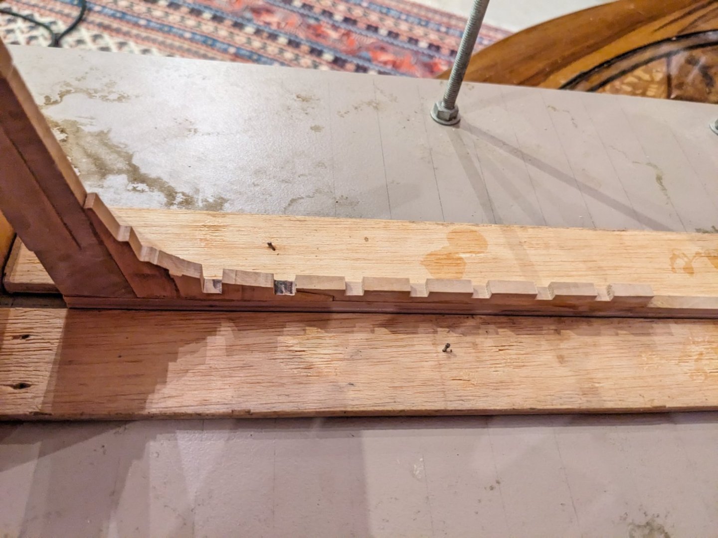
Finally the main structure of the ship is finished. There are several defects, especially in the aft area as depicted in the monography. But those are acceptable. I planked the deck. I will try to plank the hull later and perhaps deveelop the planks for CNC cutting. Speaking of CNC, I decided to cut the first parts, starting with the keel. I wanted to start designing a process and see wether it had any chance at all to be successful. Results are mediocre so far but I should improve. the process is the following: - Designing the part with Rhino - RhinoCam is too expensive (but new licensing option are available for 2023 that may be interesting). So I export the part as a stl file - Importing the file in Vectric Aspire. It is a nice piece of software available at my club. 2-sided machining seemed quite straightforward. - Preparing 2-sided machining on Vectric. Ok, it was not so straighforward. Tip: using 3 asymetric dowels to reposition the stock when machining the other side. Use tabs to avoid motion of the part. - I bought nice planks of wild cherry. But they are too thick: 25 mm, wich is too much for 1mm bits. 1 mm bits are sufficiently precise to capture details and approximate rectangular pockets for instance with the corners looking too 'round-shaped'. The issue is that 1 mm bits are not that long, otherwise they would be too fragile. So a first step roughing the stock with a 1/4'' endmill is necessary. Roughing area should include lateral margins around 1 cm to account for the width of the router collet when the 1mm finishing bit plunges far below the surface of the stock. - Cut and hope for the best. I will not summarize here the pain of this trial and error endeavour. It was fun in the end though. The first part is not that nice. Many errors. But the next will be better. I shall use the mill to improve the accuracy of some corners but the surface is real smooth .


-
work in progress.
-
ancre La Belle 1684 by Oliver1973 - 1/36
Kranck replied to Oliver1973's topic in - Build logs for subjects built 1501 - 1750
I find your skills in milling remarkable. Do you use the Proxon Mf70 or do you have more 'professional' tools? Keep up the great work ! -
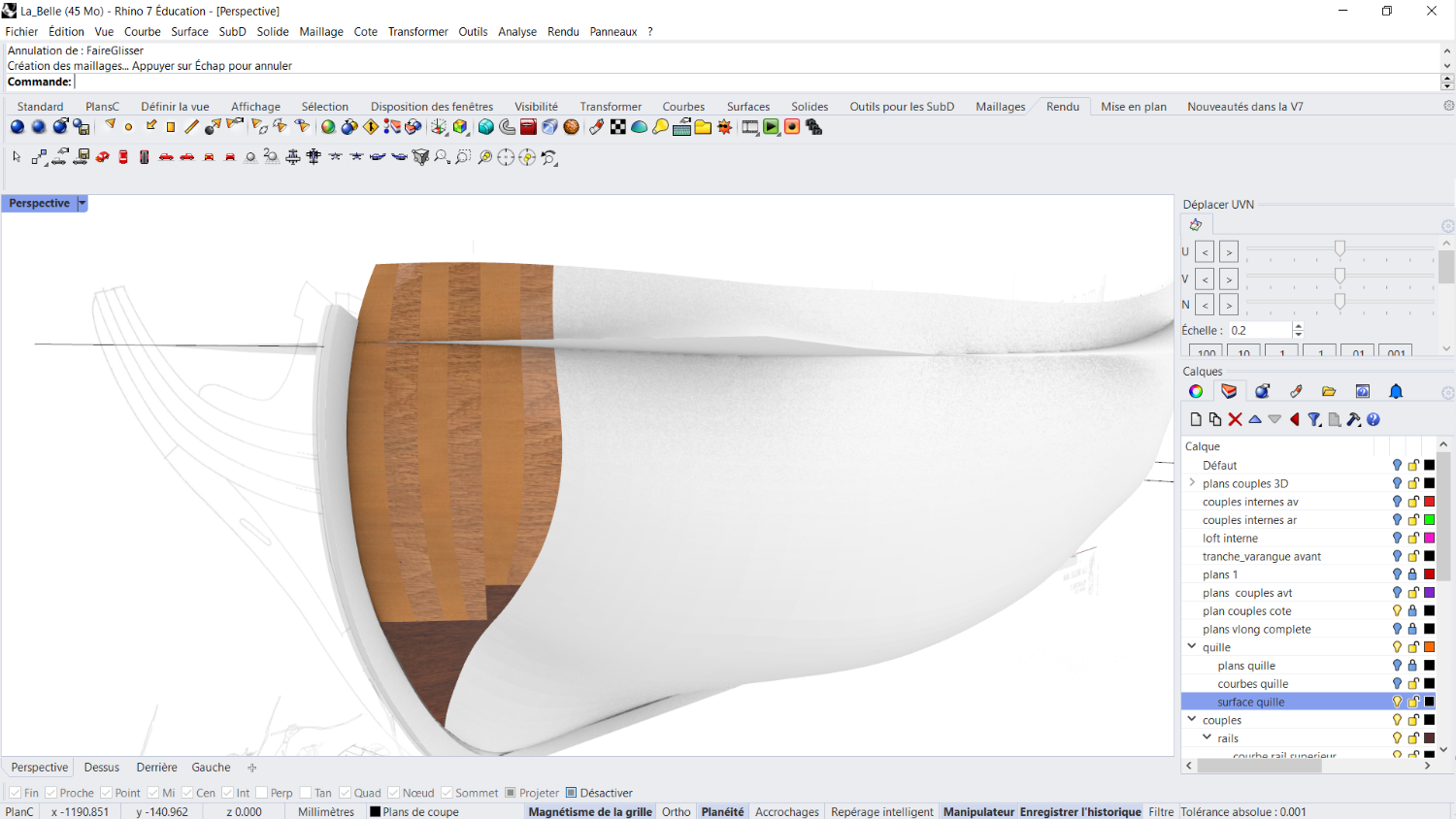
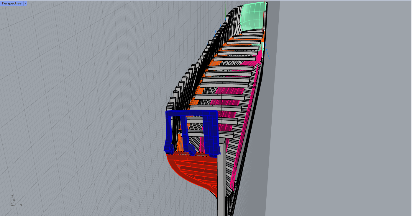
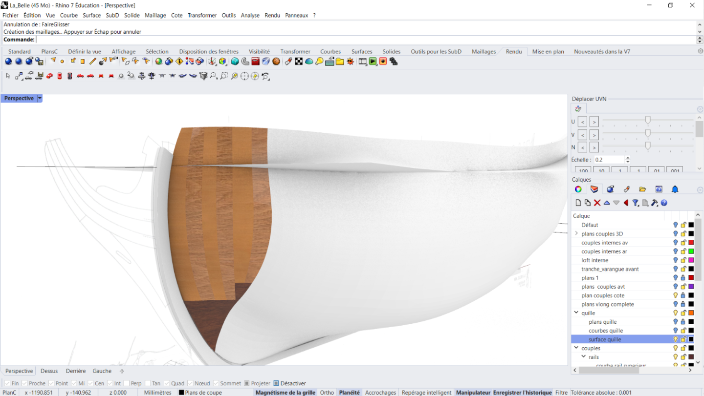
Reworked the inner surface once again The outer one is fair. In color, the old frames. In grey, the new ones. Much fairer. I managed to get something much smoother and removed the bumps here and there. Still a bot of work at the stern, where I will keep the sternpost (the design is fine, no need to do that again). I'll have to deal with the bow too. But how? Many possibilities. Sorry for the lack of consistency in this log. Ideas come and go, and I write what I think is right at the time...
-
Thanks for the clarification Alas, my work is not proficient enough to even resemble a copyright violation... Cheers, Nicolas
-
Hi, I did try to just offset the hull surface. There are two issues: - If the surface is offset to a defined thickness, the top of the frames is too thick and the lower part is too thin. - I the offset is variable, it is very difficult to get something nice in the stern area with the tools I found in rhino. It gets very bumpy and not accurate since the offset variation is linear. I will think about your method, I'm not sure I understan. Best regards, Nicolas
-
The link to the rdm files follows, if the rules of the board allow it. https://drive.google.com/file/d/11s1BxOKmqo73I2yY2q8fYigun9q_qBle/view?usp=sharing I removed everything that was not necessary. I kept some image files within. The external surf is not linked to the curves because I tweaked the UVN motion, which breack history. However, for the internal surf, you can still use curve motion to control the loft. This is the best I could do so far. The frames I get are not that bad. I chose not to draw the bow this time (which might be mistake).
-
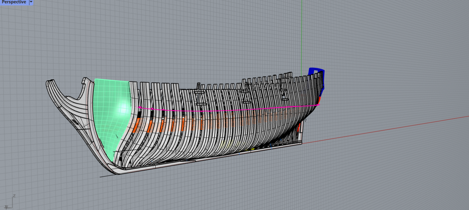
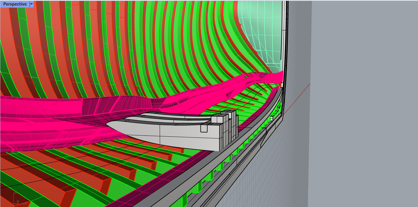
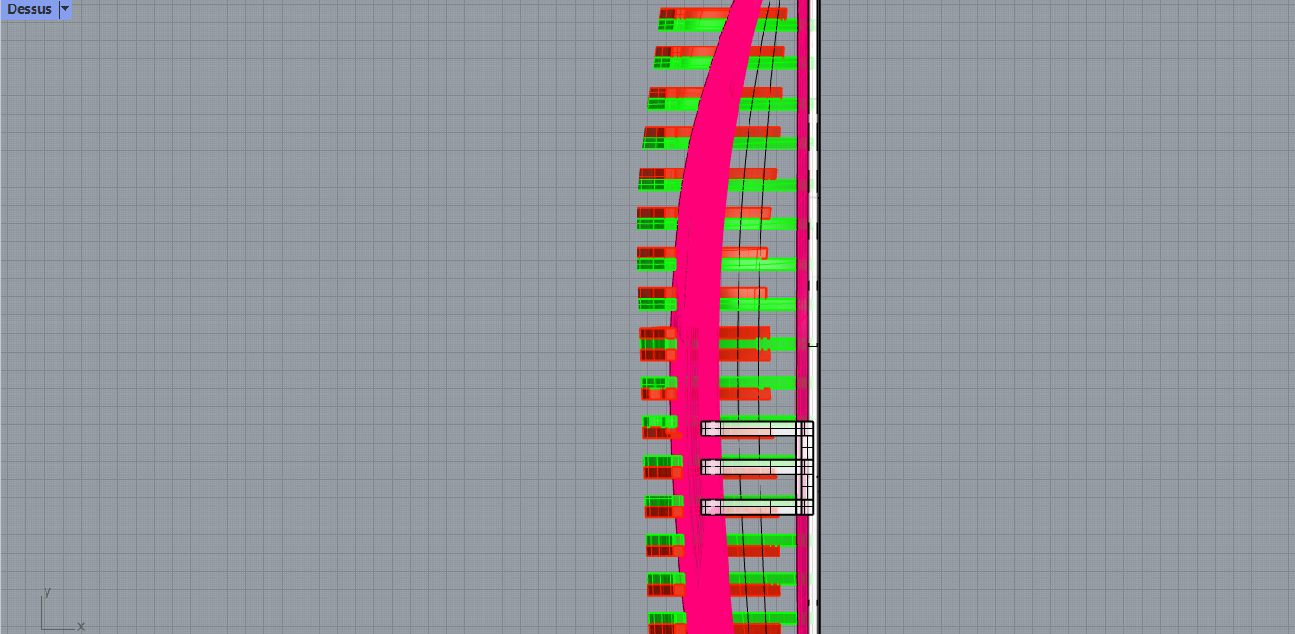
Thank you so much for your interest in thiws work. This is really important work for me as I intend to do this properly for each ship I build. I think that this is not bad for a piece of software I didn't know just 2 months ago but still... I fully agree with your statement: It is worth getting a correct loft before proceeding with the rest. I started lofting again with without using 'normal', it is much better. But the accuracy cannot be as great as intended and I get some curves quite far from the monography. I lofted from the stations drawings. The issue I run into when using your method is that when I extrude from the futtocks joints with the thickness at that point, the resulting frame (whose section I could use to loft the inner surface) is too thick close to the deck and too thin close to the keelson. Unlesse I misunderstood our method ! but I agree it should force the loft too behave in the same way as the outer surface, which is what we want. The pink surface is obtained according to the following: - Draw the contours of the hold planking in the XY plane (monography) - Project those contours on the inner surface - Create a surface joining 4 sides of each plank - Solid Offset this surface to get the plank. This is too complicated, I should use your method to cut the inner surface. In your second post, you mention a picture of my first loft. I discarded it for those same reasons: isoparms were too nasty I will prepare today a file with my new loft. I tried a new method to get the bow in a separate way. Many thanks PS : Just bought some wild cherrytree planks. Eager to machine !!
-
Dire times. I designed some more elements in the hold and at the bow. I tried to project the contour of the inner planking of the hold, but the results is not satifying. Obviously, it is wobbly and irregular because of some bumps on the frames due to an inner surface that is not fair. The outer surface if much better. Projecting the planks and adding thickness on those frames highlights the defects of the surface. It should be better with actual wood, since there will be some rigidity with the material and some sanding that will allow for a compensation of the irregularity. But up to what point? I'm not sure it will be sufficient to smoothen the biggest bumps. I don't know what to do. I'm not sure I can get a fairer hold. Any slight offset or UVN change in the lower part of the hull surface results in big changes in the actual XY position of the projected contours of the planks, which is quite natural since the surface is almost flat at that location. Is there another way to model those planks? Should I loft again the surfaces? Should I stop designing here and get to woodworking with the hope of compensating the defects?
-
ancre La Belle 1684 by Oliver1973 - 1/36
Kranck replied to Oliver1973's topic in - Build logs for subjects built 1501 - 1750
Do you feel that this Paulimot is better than the Unimat ? Easier to maintain maybe? Wondering about buying one... -
I designed the decoration of the poop with Aspire. It is not exactly as Baudriaut drew it, but I had the opportunity to use a bunch of components already available. It should be ok to machine it with a very small engraving bit on boxwood. I worked quite well with the decoration of Le Cerf.

-
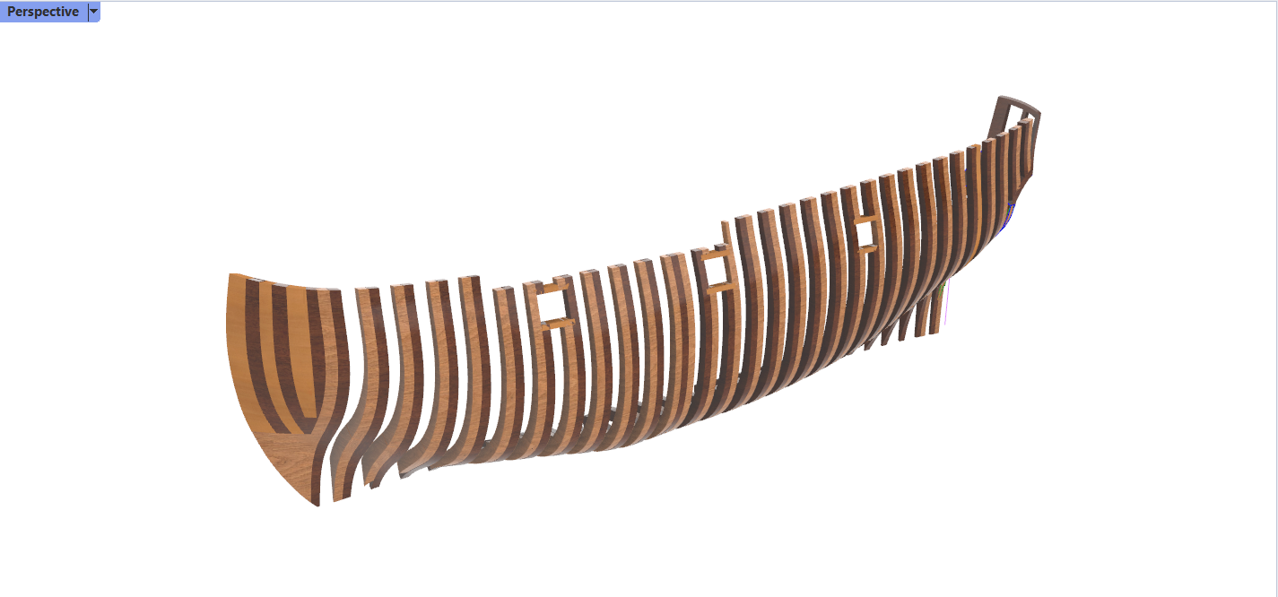
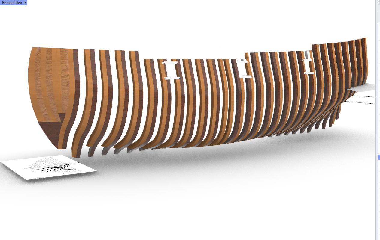
Some update: - I redrew and lofted again the outer and inner surfaces. Much better. Some futtocks are still a little too thick, especially towards the bow, but this can be dealt with later with smaller cuts with an uptdated version of the inner surface loft if needed. - The stern is quite satisfying. Lots of projection of curves on surfaces etc, and a final touch directly dealing with solid edition but it is quite accurate. - Currently cutting the futtocks in smaller parts as shown on the blueprints. Next step will be setting the decks.
-
And what is a porcupine ? Except from the animal...
-
Thanks, that is an explanation about older ships that I had never heard before. Very interesting. I think I will use a 2 sided CNC job job milling both sides of the frame. I'm interested in the process. I hope it works without too much loss of accuracy. But the whole job of learning rhino to drawing the frame and finally machining them is quite rewarding I think. I'm still fighting with the bow now, trying to avoid the singularity, but the McNeel forums are full of clever tricks to deal with that. Good luck !
-
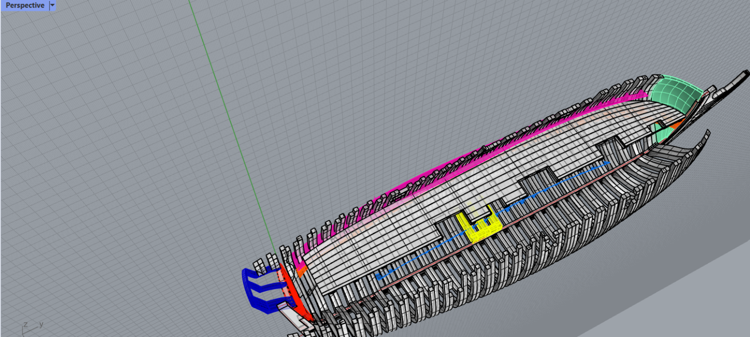
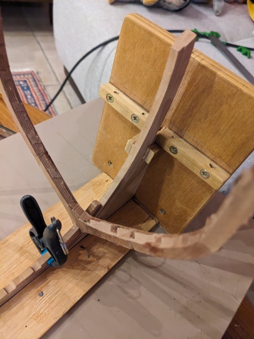
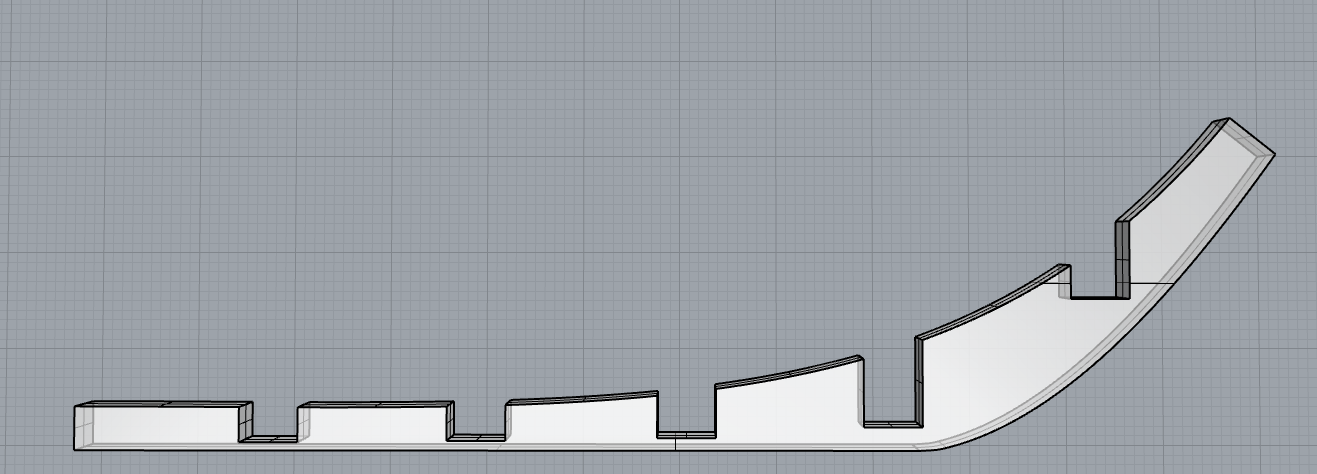
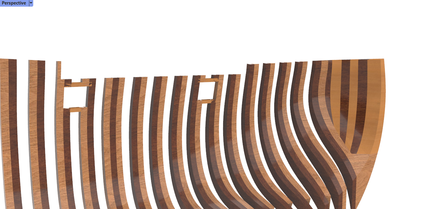
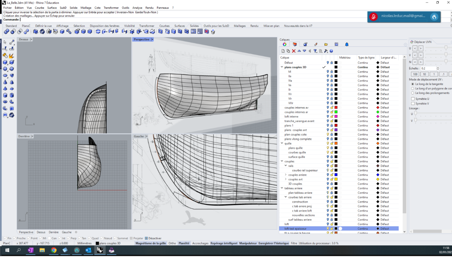
So, Things are getting along. I'm doing better with the software and the overall strategy. I was about getting started cutting frames in 3 when the harsh truth struck me: I got an issue with the overall thickness of the frames, mainly at the center of the ship. As you can see on the second picture, I only added thickness on the outer surface of the hull. But this thickness is not the same everywhere. I deemed it negligible at first, but there is up to a 3 mm difference between the blueprints and the frames I drew. I found out just today how to edit the inner surface of the loft. But it is a serious setback, as I must come back to an earlier version of the work. There is also the alternate solution to modify each frame individually. I doubt it would be rewarding. Thinking.

-
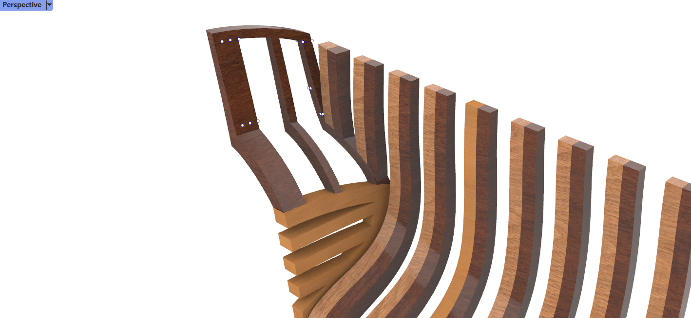
Bow (allonges d'écubier ? Futtocks?) with a first try at choosing a material. I had no idea these were designed this way in older naval architecture. It is quite satisfying to see that the monography is quite accurate for this part of the ship. However, I'm begining to have second thoughts about how to actually make these parts. No way 3D CNC is sufficient.
-
ancre La Belle 1684 by Oliver1973 - 1/36
Kranck replied to Oliver1973's topic in - Build logs for subjects built 1501 - 1750
Very nicely done ! You have a small lathe at home? -
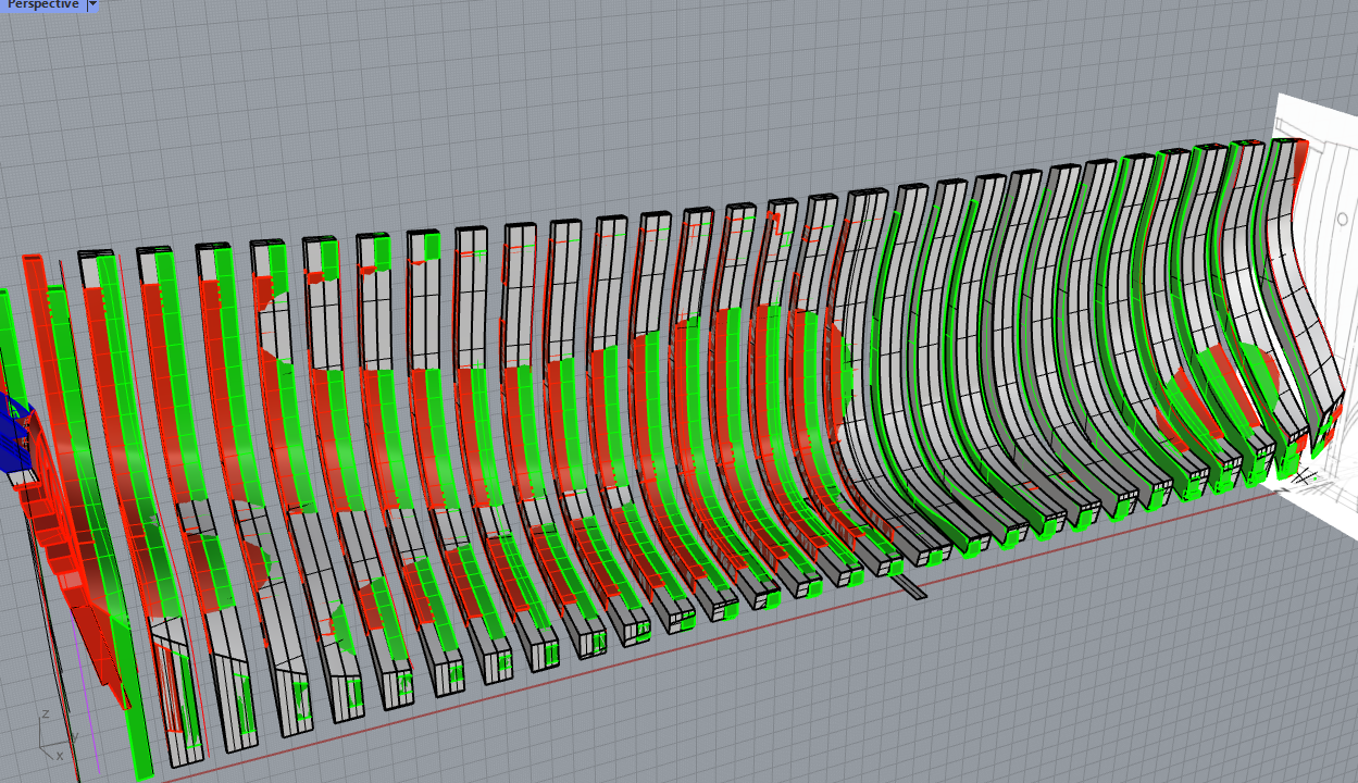
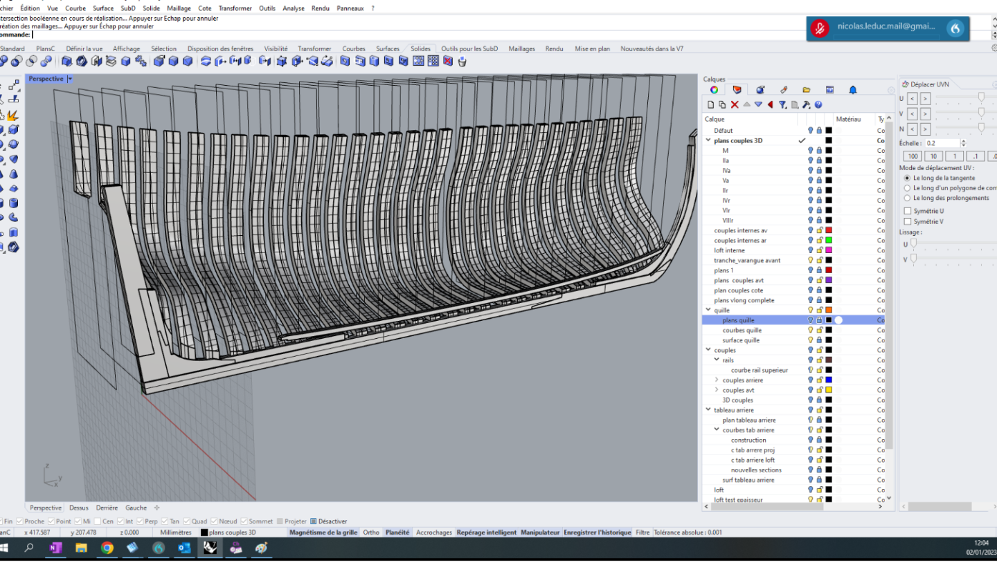
So, A happy and fruitful year to you all. May our ships remain fair and waterproof. I worked some more on the surfaces. Unfortunately, more issues than successes. * Working with the outer surface of the frames and connecting it to a lofted 'inner surface' is actually very difficult: The tangency and paralellism of those two surfaces is somewhat inaccurate and hard to control, especially at the bow and stern of the ship. As a consequence, some frames have a thickness that does not change properly along the Z axis * I chose to ad thcikness to the sole outer surface instead. It is safer but less accurate. I should add some thickness later to the base of the frame, modifying manually the surfaces of each frame one by one. * I found that I lack proficiency in the reading and understanding of the blueprints. I'll ask some friends about that. * A lot of work to solve (partially) the issue of the continuity problem in the bow. It turns out that the 'wirecut' tool is a lifesaver for it.
-
Besides, I'd be happy to have a look at your pdf, I'm sure I would learn a lot, should you consider to upload it once more. I followed your rhino hull lofting webinar with great interest (I mean, I DO now understand english as spoken by an australian) but I find it difficult to apply the method to round hulls, mainly because : - Defining what a fair surface is seems to be quite difficult, as compared to more recent ships - as such, I ssem to lose a lot of details of double curvature in some frames when I try to smooth a bit too much - The 'knot' or error in the loft between the bow line and first station line. Not sure how to deal with that. And it does provide weird lines on that spot, which is quite logical considering the mathematical nature of Nurbs, but still annoying.
-
Hi, Following with the greatest attention... Did you loft the surface before designing the frame? I'm still pondering the options about my La Belle with Rhino (beginner though) And what about CNC? Do you intend to use a 4D apparatus? Otherwise, I suppose you cannot fully mill the frame on all sides, right? Best regards, Nicolas
-
Hi, I agree that this is not essential to the building of the ship. I could do it by hand. But I used to be an engineer and I'm having some fun designing the ship on the computer too. It is clear that for the moment, it will be extremely time consuming. But in future builds, it should be faster and more useful. Let's say it is a proof of principle experiment I'd really like to develop and CNC mill the planks. Besides, I have no experience with naval architecture so depicting the parts on the computer helps me visualize the overall construction of the ship.
-
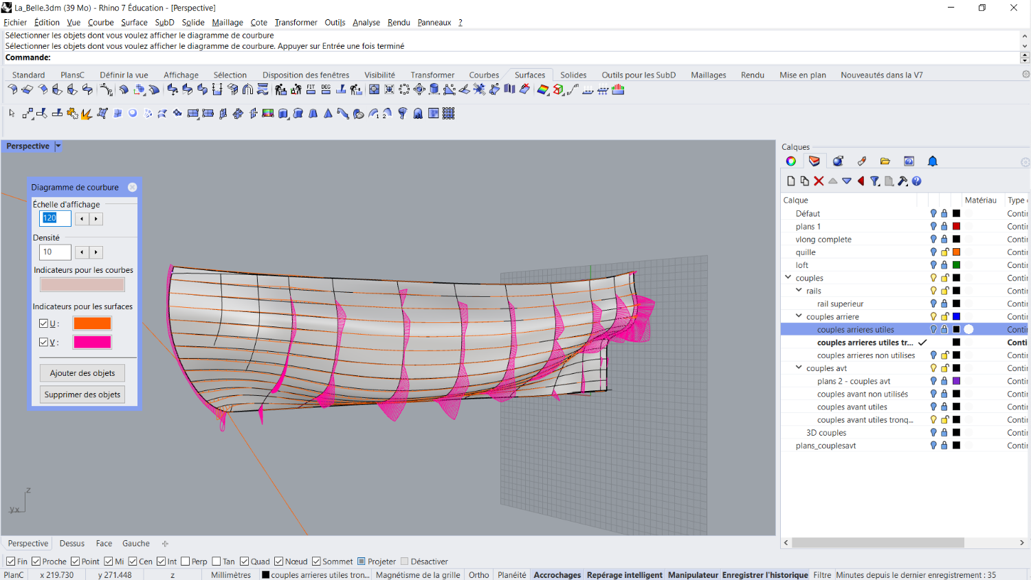
Getting there. The tormented whirlwind (funnier than mathematical singularity) in the front disappeared due to the creation of a new section (new rhino command for me!) at the appropriate distance from the bow. I prolongated the surface at the rear (thxs to wise advice from Waldemar). But let's face it: It is a pachidermous monstruosity. The curvature diagram is a mess. Let's ponder and meditate about fairing tomorrow.