Kranck
-
Posts
69 -
Joined
-
Last visited
Content Type
Profiles
Forums
Gallery
Events
Everything posted by Kranck
-
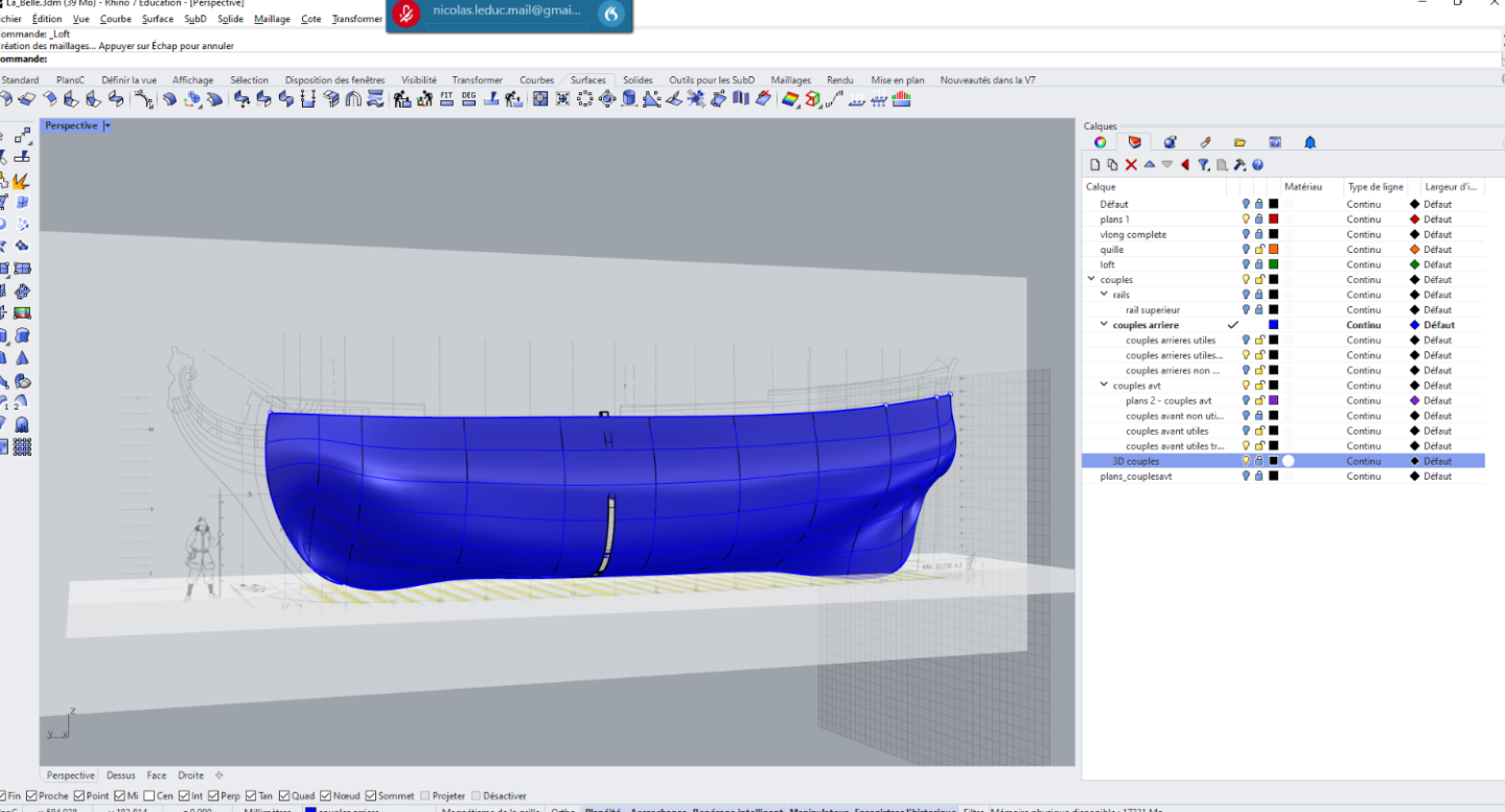
That is a very precious post. Thank you so much. It will solve a lot of issues, CNC milling wise. I'm struggling with surface lofting at the present, and quite happy about it (gotta sweat a little to get something nice in this life !). Your previous explanation will come very handy when limiting the loft to the queel (that I just finished drawing). Now, time to remember to the joys of gradients and curvatures. By the way, I reviewed your previous posts and I can confirm that I am also thinking about drawing the INNER master surface for the full delineation of the frames. However, since there is no direct 2D projection of those curves, I was thinking about cheating a little and using the variableoffsetsurf fonction: i,e, offsetting the OUTER master surface with a variable thickness to account for the thicker base of the frames. Not sure it will be that accurate though. Best regards, Nicolas
-
So, First try with rhino lofting. I fight with the geometrical errors of the monography as well as my own incompetence. Yet, there are several interesting resources on the forum to learn about lofting thoses surfaces. The aim would be to intersect the inner and outer surfaces of the frames to get a perfect shape before planking. But well, this is a remote goal. For the moment, time to beautify this loft. I will follow a step by step process according to the webinar one of the guys here gave a few years ago. Darn rabbet.
-
ancre La Belle 1684 by Oliver1973 - 1/36
Kranck replied to Oliver1973's topic in - Build logs for subjects built 1501 - 1750
Just what I thought Thank you very much ! I'll try to update my log regularly while designing with rhino. Best regards, Nicolas -
ancre La Belle 1684 by Oliver1973 - 1/36
Kranck replied to Oliver1973's topic in - Build logs for subjects built 1501 - 1750
Hi, Thanks for the anwer. I put some colors on one of your log photographs then... Huc (as well as riccardo mattera there https://l-arsenale.forumattivo.com/t7-la-belle-1684-scala-1-24-di-riccardo-mattera) seem to reduce the width of the area highlighted by black rectangles, i.e the sternpost, deadwood and the whole upper part of the queel. On the contrary you seem to reduce the width only on the sternpost, rear part of the queel and deadwood (black dots) and then gradually return to full width (red dots) on the queel while engraving a deeper rabbet. I don't know if i'm making sense...
-
3D Brig 'Rose' in Blender 3.3x
Kranck replied to 3DShipWright's topic in CAD and 3D Modelling/Drafting Plans with Software
Sorry to hear that... Yet, the beauty of your works is astounding ! I'd be happy to get half your talent. I'll relax and watch what you'll show -
I'd go with a diagram, sir ! Seems to me that you define the rabbet location beforehand, which is fine, but what about its shape? Since the rabbet shape is sure to be different along the queel
-
ancre La Belle 1684 by Oliver1973 - 1/36
Kranck replied to Oliver1973's topic in - Build logs for subjects built 1501 - 1750
Dear Oliver, First, my congratulations for this great work! I'm trying to do my first admiralty-style model and it is la Belle too. I just started drawing it with Rhino (first try too... although I got some experience with Catia !). I was comparing the video of Bernard Huc and your work. I got an issue with the sternpost, deadwood and rabbet: - Huc seemed to reduce the width of the entire upper part of the queel (where the frames are set) to that of the lower part of the sternpost (around 4 mm), where the garboard will end. Same thing for the rear deadwood part. - On the contrary, you seem to keep the width of the queel to around 7 mm almost all along its length, with the exception of a narrow rabbet. However, the lower part of the sternport still must be reduced to 4mm. How do you manage the transition? On the photographs, it seems that you tapered the sternport as well as the deadwood and gradually transition from 4mm to 7mm the width of the queel from stern to bow, as the rabbet gets deeper. Could you enlighten me about that? The first option seem tempting as I want to cut the parts using a CNC machine and that would be much easier... Thank you for your reading and kind answer; Best regards, Kranck PS: as far as CNC milling is concerned, may I mention the Vectric Aspire pice of software, which makes engraving rather simple as compared to Blender, for those of us that do not master the latter. PPS: As a resident of Germany, do you have a favorite shop for wood? I can't help but noticing your pearwood (?) is beautiful -
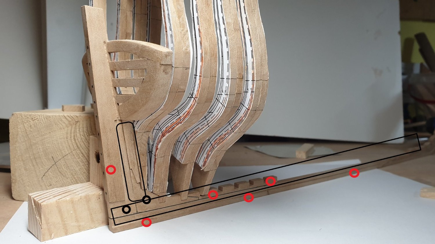
This is some REALLY great advice about many basic aspects of the task. I had not given thought about a bunch of them. Thank you; I will start lofting the hull. Hesitating about ending the surface with the rabbet in the queel. But several ideas come to mind: - Drawing the rabbet by hand according to the blueprint and ending the surface with this line. - Giving some thickness to the hull surface after lofting it until 'inside of' the keel, then use a boolean operation to engrave the precise shape of the rabbet in the keel. Considering what you just wrote, the second option seems to be much wiser. What do you think? I will update some rhino screenshots on my log after pondering the options. The ultimate objective would be to develop the 3D surface of each plank of the hull, then project on a 2D sheet of wood and use my CNC machine (3D but quite a large one) to get machined planks already tapered and skewed along one of the axis. Should be fun. I lack time though !
-
Well thank you very much for your kindness. I m pretty much a beginner for non parametric software. So my questions will be rather dumb ! 1. I am using the 2d blueprints of boudriot to loft the surface of the hull. But i will draw and design each frame. Do you have a general opinion about this process ? Is the lifting useful or do you just design the frames without fairing ? 2. How do you position each part in the ship ? Say, i want to set one frame on the keel. Both are intersecting 3d parts. Do you use some kind of constraint or do you just set it as precisely as you can ? Or maybe can you cut the frame using the queel ? What about the planking ? Good lord, these questions are so vague it shows my current utter lack of skill in the field! Best regards Nicolas
-
3D Brig 'Rose' in Blender 3.3x
Kranck replied to 3DShipWright's topic in CAD and 3D Modelling/Drafting Plans with Software
Hi ! This is exceptional. I'm gonna try to do the same with Rhino, with the intent to get CNC output for the parts. Yours is to remain binary? -
Hi, This is some great work. I think I'm gonna try and do similar with La Belle. Well, with a much more limited experience and skill... I'd like to 3D design the parts and laser cut and 3D CNC as many parts as I can. Do you mind if I ask you a few general questions about the way you deal with things with Rhino? Best regards, Nicolas
-
ah yes, my bad ! Thank you
-
Hi Druxey, I agree that for someone with no CAD expertise, the whole process will be actually longer than carving by hand... But I lack the carving skills ! Unfortunately there is no one around to teach me and I lack the talent for this kind of art. Besides, I do love looking at 3D models on computers. It does help me as I have some issues visualizing a ship from blueprints only. Another pro is that you can easily start again if you fail with one part or have trouble with assembly. And I find that learning CAD is quite rewarding by itself. Lastly, it means that files can be shared within a community, which could be great. We'll see. Lot of work ahead.
-
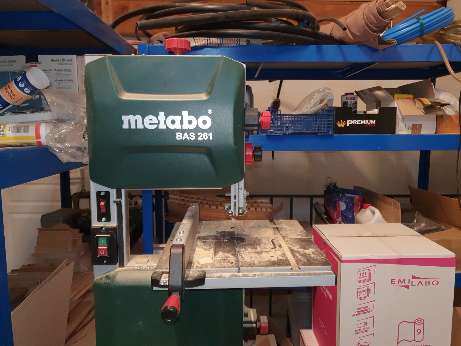
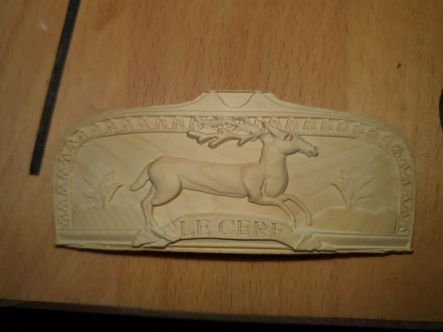
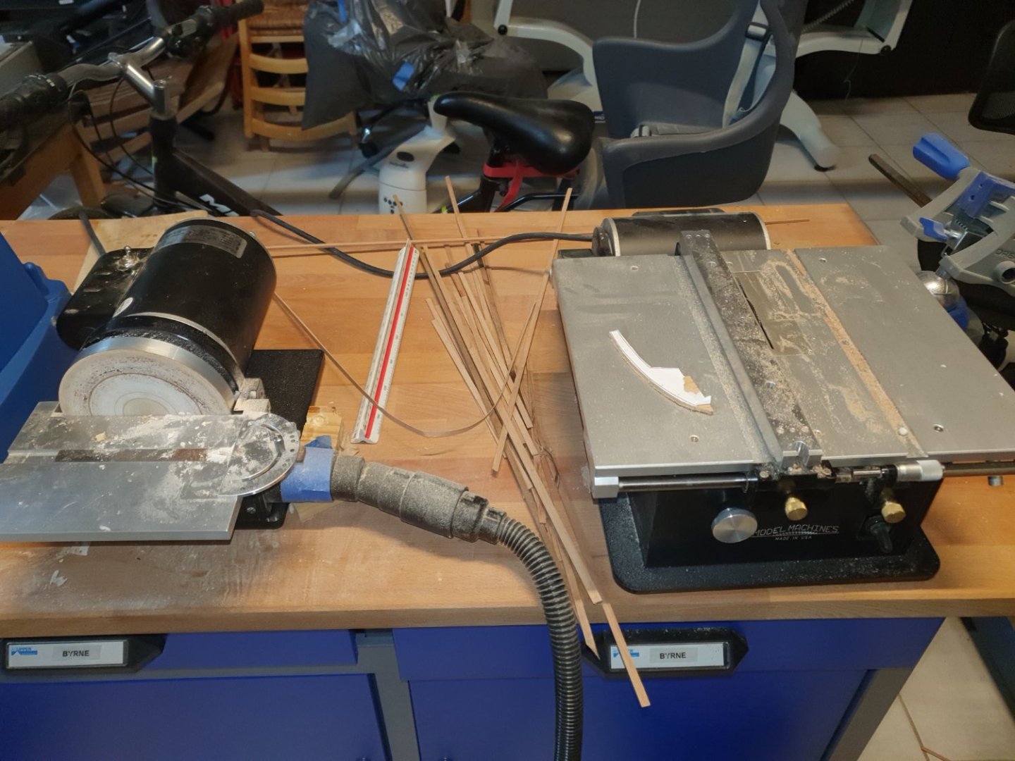
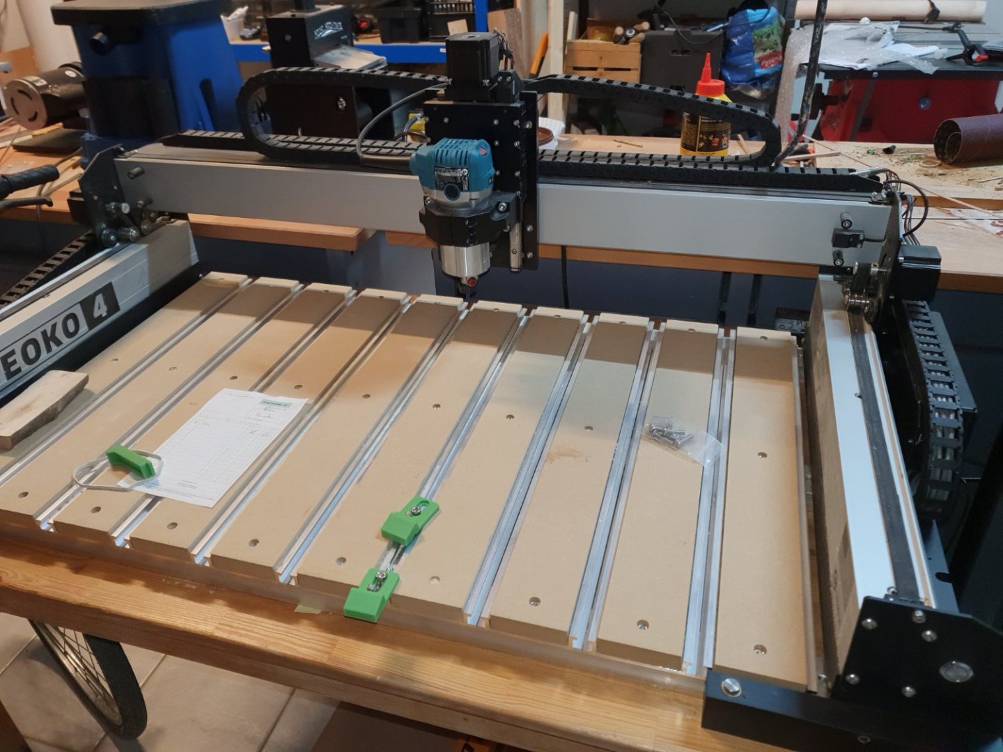
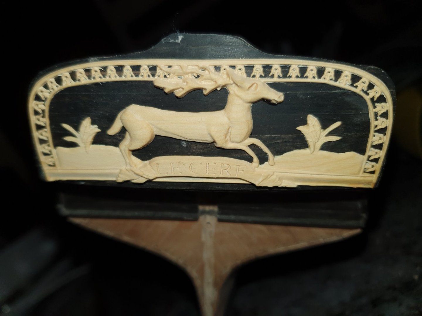
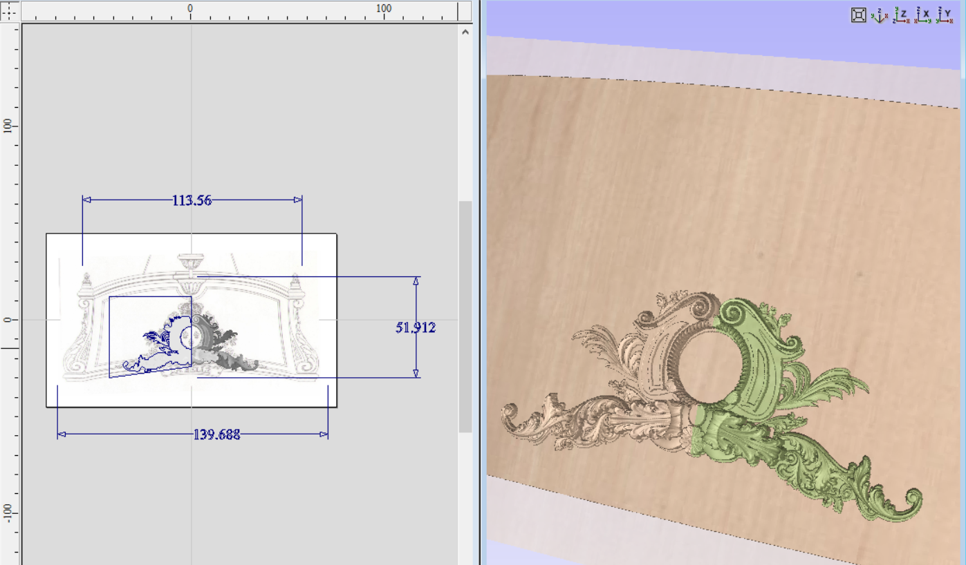
As I dived into the hobby 2 years ago, I had no idea of its depth and the time it would consume. I started with HMS Victory, a common mistake I suppose. I had bought a kit for my mother that had just retired. But she told me it was too difficult for her. And, well, she had started several hobbies at the same time. So I gave it a try. I had no previous knowledge of woodworking. I'm a medical doctor but I got an engineering master earlier. So I supposed I should be able to get the best of it. But this ship was a mistake. there is no way I could master it with 3 files, some glue, two cutters and absolutely no experience. I spent almost one year on this kit though. I managed somehow to finish planking. At the same time, I joined a modeling club that happens to be quite active in my area. Interestingly, they used to manage a small ship museum in a parking building on one of the villages that border the mediterranean sea here. The museum closed when they got older, but they are still actively building. Most of the members do scratch builds. Most are over 75 though... This is in no way comparable to the guilds that are active around Paris, and the quality of the builds is not as high, but those folks are nice and I'm a beginner ! So I started building from scratch Le Cerf, from the monography of Boudriot. I learned a lot. I just finished planking. I use this build as a draft to test various procedures and learn as much as I can. I do not intend to log this build. I decided to start an 'admiralty' model as I feel that I would love dealing with the intricacies of ship carpentry. I will use what I learned with Le Cerf to do what I can with La Belle, another small ship well described by Baudriot. I have access to lots of books and I bought a lot of tools these last months. Besides, I intend to design on the computer as much as I can. I 'd like to CNC as many parts as possible, especially to get precise and fair measurements for the hull. I bought or got access to the following tools: - Byrne's saw, thickness sander and disc sander. Those are the best, enough has been said about those tools. As another modeler truthfully said: the only limitation is my current skill. - Shapeoko 4 XL: this is a nice 3 axis CNC that allows pretty much anything from engraving, moulding or designing bulkheads in any kind of wood and so on. Just great. I used Fusion 360 to design the hull of Le Cerf but I feel it is too much oriented towards mechanical engineering. I use Aspire for art thingies (sculpures and so on). and I'd like to use Rhino for the hull (bought a student licence as I spent some time at the uni again for an oncogenetics diploma this year). Wasnt all for naught then. Here is an example of what can be done with it : And after sanding the background, I could glue it to Le cerf: - Metabo bandsaw: this is nice. Much better than the small modeling saw yet accurate. - Proxxon Ibs/e. God bless Germany. This is also a marvel. My first steps with la Belle: - Scanning all blueprint and printing a copy. - Learning what I can about the hull of those ships. I got a few interesting books to keep me awake at night. - Learning Rhino (that will take time...) and designing the keel and berth of the ship. - At the same time, design the decoration with Aspire. I gave it a try for a few hours: Aspire already provides a lot of decorative patterns that can be used. Since nobody actually how what those really looked like on the actual ship, I decided to give some leeway to my imagination. Like the Cerf decoration on the stern, I will engrave it on boxwood. But finding the good bits is a pain for such tiny details. Beside, 3D CNC are inherently limited to Bas-relief 2.5D engraving. There is no way I could sculpt intricate full 3D details. We'll see. I'll post more when I get something nice with rhino (could be very long!).


-
HMS Victory by Kranck - Corel - 1:98
Kranck replied to Kranck's topic in - Kit build logs for subjects built from 1751 - 1800
Ok so I officially close this topic. I abandonned the building of this ship. It was too difficult for my feable crafts at the time. But I did not abandon the hobby ! It turns out that there is a fantastic modeling club around and I thought a lot about how to start over in a way that would let me improve my skills in a satisfying way. So I bought decent tools and I started to build le cerf, a small french cutter from the monography of Jean boudriot. It is very satisfying, but for me it is a kind of a draft, I'm learning to model ships one piece at a time. I have no beforehand knowledge about ships except that they float in water so well... As such, I will not display here the results, there are a bit rough. The hull is quite nice and I use CNC to cut it after drawing it with Fusion 360. I messed with the upper hulll (muraille?) bit time as I did not think about it at the time of hull design. So well, it is not that great but it teaches for the next time. Speaking about the next time: I feel sufficiently confident now to start a small 'admiralty type' model which will be built very slowly, using for each step what I learnt building le Cerf. I chose 'La Belle', again from the monography of Jean Boudriot. It is supposed to be simple enough for such an endeavour. But to do so, I want to design as many parts as in an in 3D and used CNC. Should you be interested, please have a look at my second build log. I will start listing all the tools I got and the ones I intend to use (Christmas came early this year from Florida, thank you god for the life of the Byrnes !) including the Shapeoko 4 CNC machine. Thank you all for all your advice! -
This is beautiful. i m currently building le cerf After modeling the Hull with fusion 360 and cutting 3 D frames with a CNC router, but I m nowhere near this level of accuracy ! I ve decided to learn fairing hulls and developping planking with rhino but resources are scarce... A few very interesting topics on this forum but this kind of things requires a good deal of effort to learn properly. Where or how did you learn how to do this kind of work ? Best regards, Nicolas
-
I see. Thank you for your comments. I'm hesitating buying a much more powerful CNC router such as the shapeoko, as I intend to use it a lot for the modeling hobby. I admit that my CAD skills are much better than what I can do with my bare hands
-
Hi! I made my first steps with the 3018 PROver yesterday. Lots of fun, but several issues to solve before getting some accuracy. Getting from Fusion 360 to Candle and then actual routin is a laborious process... I also find a lack of data about the usual settings for the milling of , say, plywood with this router. You mentioned earlier that you used conservative parameters. Do you mind sharing about it? I first used a 3mm (imperial 1/8''?) corn-shaped end mill genmitsu sells with the machine, at 10 000 rpm and 1 mm optimal load but the results were quite disappointing. Lots of vibrations too. I'm trying to machine the bulkheads. Do you think other kind of bits shoud be appropriate? Steep learning curve for a newbie
-
Turns out it was a matter of setting the Timeline on or off. Advice for future readers: don't set it off... it messes up with the parametric contraints.
-
Hi, I'm following your steps to shape the hull of the cutter Le Cerf. The blueprint are sufficient to perform quite an accurate job. However, I'm quite new to fusion 360 ad something is maddening me: Whenever I try and tweak some of the sketches, the intersection points between rails and profiles are not coincident anymore. I guess It is some kind of issue with the constraints I set, but there seem to be a rather large number of issues of the sort as far as 3D sketches are involved. For instance, If I tweak the sheer line aven a little bit, I lose all the relevant snap info for all stations... Do you have any kind of advice about this matter? Cheers !
-
Hi there Just a few words to congratulate you. She looks nice ! I spent a few months far from my Victory. Still settling in the house, had to to some masonry and take care of the garden. Hope I will get some time for the construction, yet planking is far from finished. Best regards Nicolas
-
Excellent work, as always... I'm taking some time off, as I got my hands full with painting and redecorating my new home. I just have a few minutes from time to time to add some planks.
-
Looking good. I think the blue paper provided by Corel is a bit too bright. I'll use it, but slightly stained.
-
HMS Victory by Kranck - Corel - 1:98
Kranck replied to Kranck's topic in - Kit build logs for subjects built from 1751 - 1800
just a little update about the second planking: I dealt with the upper part problems with a nice sanding that hid the defects... I'll ponder a bit more for the next ship. Some issue with planking of the bow: I suppose it is a common problem but the planks won't lay flat on the bow as I progress towards the keel. It is a simple geometry problem , really, but egde-bending seems a no-go. I thought about spiling but I only got the weed provided in the kit. I read in one planking manual that in that case, I should perform a 'directional change' that seems to be basically a massive tapering of one of the planks : https://www.modelerscentral.com/blog/how-to-plank-the-hull-of-a-bluff-bow-model-ship/ So much actually, that the plank will not touch the keel at the front of the bow. I think this is efficient but rather inelegant as I suppose that for the second planking all planks should take the full lentgh of the ship. What do you think? either way, I must find a solution or I won't be able to plank this bow. bests, Nicolas -
HMS Victory by Kranck - Corel - 1:98
Kranck replied to Kranck's topic in - Kit build logs for subjects built from 1751 - 1800
Thank you all for your help ! I also think that with proper finish and behind the raft cranes and all, this should not be visible at stern I hesitate between solution 2 and 3... I think the issue arose from 1)a slightly incorrect setting for the wales 2) the incorrect notion that upper planks should not be tapered... I'll think a little more about this.