


Matrim
-
Posts
1,401 -
Joined
-
Last visited
Content Type
Profiles
Forums
Gallery
Events
Posts posted by Matrim
-
-
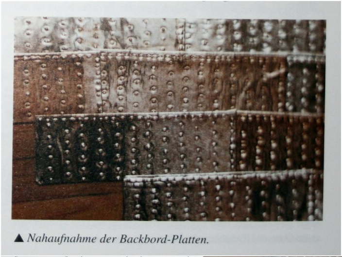
In another book from the ancre publications which I mentioned already some times,
the book THE ART OF SHIPMODELING ---- by Bernard Frölich
some more very interesting photos were given us by the author.
In this book he is showing over several pages the way he was coppering his 1:48 scale 16-gun brigg "LE CYCLOPE"
(a sister ship of the Le CYGNE from the former post)
He was using for this model a very thin copper folio which is usually used for electronic works
with a thickness of 36 microns (0,036 mm) and an self-gluing side.
So no extra glue is necessary, only removing of the protection folio and gluing directly on the planks.
This material (he is writing) is available in rolls with width of 5 cm and length of 16 m.
Due to the extreme thin material he is able to make the overlapping so realistic.
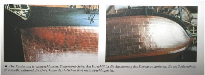
At the right bottom photo you can see that the false keel was not coppered, coppering is ending shortly after the bow!
This information you can see also and better in the following one.
Here a photo of the finished coppered hull next to the rudder of the vessel.
Very good visible is the uncoppered false-keel which was never coppered,
due to the fact that it was only necessary as a protection of the real keel against possible
carambolage demages against the sea/harbour/coast - ground.
After such a contact, the false keel was removed and a new was assembled.
The false keel was only connected to the keel with nails and/or clamps from the side, so "easily" changeable.
I did not find an information if this false keel was covered with white stuff,
but I personally do not think so, due to the fact that the false keel was more or less a spare part,
the keel as the first structural part by itself was covered from the sides by copper and from the downside from the false keel.
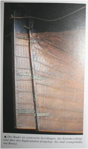
Please have also in mind that the rudder-hinges at coppered hulls were made out of bronze and not iron
(otherwise chemical reactions), so in the model they should be made maybe from brass.
Frölich received his beautiful patina of the copper-plates with rubbing the copper folio with steel wool before making the nail pattern.
In my opinion it looks much better than the shiny original copper-folio surface. -
Hallo ZZ,
in addition to the information Russ gave already I want to mention some infos coming from Boudriot and Frölich.
In the Jean Boudriots monographie of the 16 gun brigg "LE CYGNE" from ancre I found this very selfexplanatory sketch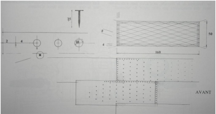
Please have in mind that this was a french ship and from the year 1804, but the principles were the same and are shown very well.
......here usual was an overlapping of the plates with only 4cm.
The used nails had a 1,8cm diameter flat head, this type of nail is very well shown.
Uwe -
Hallo ZZ,
also only for checking my own calculation, due to the fact that I am not familiar with the feet and inches etc ( like you with our metric lengths):
in scale 1:48:
1" equal to 2,54 cm and
5/16" equal to 0,313" equal to 0,795 cm
so the correct size of the "model"-plates in 1:48 should be around
2,5 cm to 0,8 cm instead of 1,7 cm to 0,65 cm (Jotika).
Maybe acceptable but not in scale!
Especially when you cut them on two sides in order to use them next to each other and not overlapping.
Maybe there are others finished and prepared copper plates available on the market which fits more to the scale and have also an acceptable "look".
Or the last and maybe best alternative: Scratch built! -
ZZ:
The plate size for 1/48 scale would be 1" long and 5/16" wide (48" x 15" full size standard plate). It takes a bit of practice and some patience to copper a complete hull, but it can be done and very realistically as long as you pay attention to scale accuracy.
Russ -
Hallo ZZ,
you are right. Originally the plates were overlapped.
Once more from Arthur Buglers wonderfull book:
Originally they were overlapped installed with a a brown paper coated with Stockholm tar was fitted between the copper and the wooden hull.
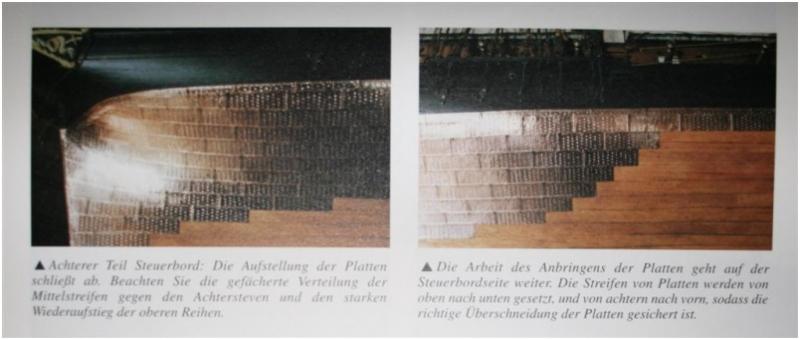
The sheets were worked with laps, clinker fashion down, and butts, clinker fashion, aft. The strakes were run as far as practicable parallel to the waterline. At the fore end they were laid roughly parallel to the fore foot
See here the photo from my post of 2nd June with the copy of Gowans book.
The best result which I saw in the last time is the coppering made by Frölich and showed very good in this photo:

You can see realy good that he managed it that the nails on the edges are very close together, so he managed it with this kind of jig to make 27 nail-heads in one row. And this in scale 1:48 (the standard scale) Frölich, Boudriot etc. are usualy working.
At fig.5 of this photo you can see the necessary plates marked with T or B for the right side or the left side of the hull. only the top row and the aft row has to have a row of nails. If the plates are overlapped, clinkered you have all around nails. BUt the used copper has to be very thin
The photo you mentioned is showing the Jotika plates which you can find available for order, but (everywhere is a but) they are produced for models in scale 1:72 and this you realize if you make some calculations:
the Jotika plates:
length 1,7 cm equal to 81,6 cm (1:48 ) and 122,4 cm (1:72)
height 0,65 cm equal to 31,2 cm (1:48 ) and 46,8 cm (1:72)
the originals copper plates (according Bugler):
length 4 feets equal to 121,9 cm means 2,53 cm (1:48 ) or 1,69 cm (1:72)
height 14 inches equal to 35,6 cm means 0,74 cm (1:48 ) or 0,49 cm (1:72)
Sorry to say but for a scale of 1:48 the plates are not the best solution , due to the fact that they are too small from the size.A closer look at Frölichs result in scale 1:48
Please have in mind that the Triton should not have the inside nails, like we discussed and found out some days ago!
-
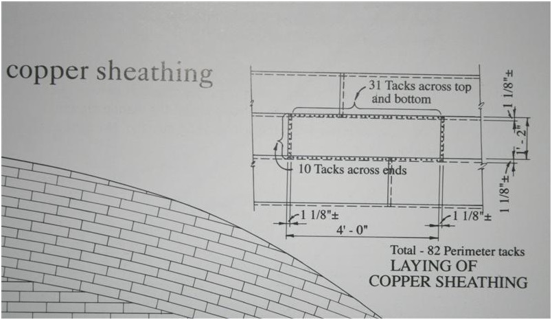
The question about the copper-plates is not leaving me, so I made some additional researches in my own library.
In McGowans book about the HMS Victory is on pages 140/141 this drawing shown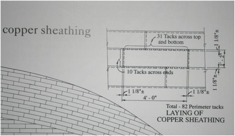
Also in Arthur Bugler - H.M.S. Victory. Building, restoration and repair it is on pages 164 to 168 the copper sheating described.
Here a frist description about the first ever sheated vessel in 1761 at the hull of the HMS ALARM (report about the success of this test was sent to the Admirality in 1763 after the two years travel of the Alarm to the West Indies) and the description of the Victorys sheating executed in 1780.
This is also mentioned in The 100-Gun Ship Victory (Anatomy of the Ship Series) By John McKay
A. Bugler is writing:
"The copper on the bottom was in sheets 4 ft. * 14 ins. No.40 gauge (28 oz.) Each sheet weighed about 8 lb. and they were secured withabout eighty-two non-ferrous, probably Muntz metal nails. The sheets contained provisions for 129 holes, but the nails required were less than this number because of the laps and butts which were usually arranged 1 1/8 ins. in width with a nail spacing of from 1 1/4 to 1 3/8 ins...........
.........The weight of the 40-gauge copper including fastenings would be approximately 13 tons."
These are sheets offered in 100 pcs packages in sizes 17 to 6,5 mm from Jotika, but also they have "too less" nails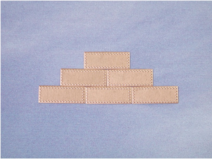
(only 16 in one and 6 nails in the other direction instead of 31 to 10 nails).
http://www.jotika-ltd.com/Pages/1024768/Fittings/83525.htm
So I have to agree with Russ, that it is realy not easy to produce the correct number of nails in the correct scale!
But nevertheless plates with nails are looking better than none of them, but this is my personal taste and opinion.
and self-produced (scratch-built) in your own eyes more -
Uwe:
For the Triton project we will be dealing with some basic coppering techniques, but the nailing question is of less importance as it more a historical note than something to be used in scale modeling. We will be concentrating on scale accuracy with the coppering rather than any strict historical accuracy in the nailing question.
The real question is whether not the nail heads can be replicated at scale. It is something that is better left off if they cannot be done within the bounds of scale accuracy. Chances are the nail heads would be maybe 1/4" to 1/2" diameter. At 1/48 scale, that means an individual nail head will be about .005-.010" diameter. Now, even if you can replicate them in scale, there is the question of would they be seen at any distance. There is also the question of the thickness of the copper material itself. The thickness, at scale, shoudl probably not be much more than .005" thick. You can find shim copper stock in that thickness and it would be good for a scale model.
If someone desires to copper their hull, it is probably better that they do not include nail heads unless they can be sure of getting them in scale and if they can do get a finished product that does not detract from the model's overall appearance. It is imperative that the builder also be mindful of the thickness of the copper. In the really small scales, it might even be better to go with paper plates and then paint them copper. Some of the very best modelers have used that method at 1/96 scale and gotten very realistic results with it. I think for 1/48 scale, the actual copper pates can be used provided they are thin enough.
Russ
-
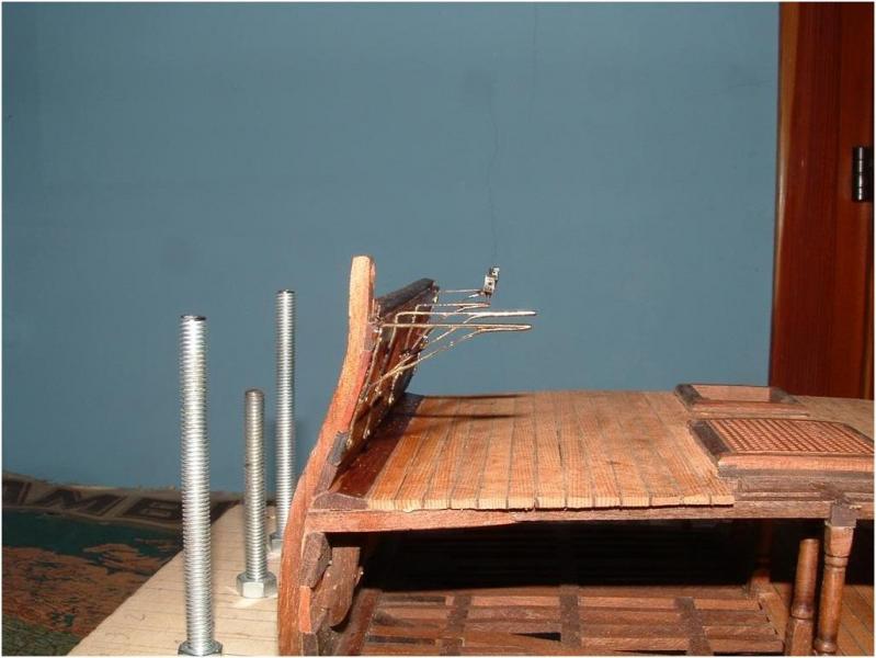
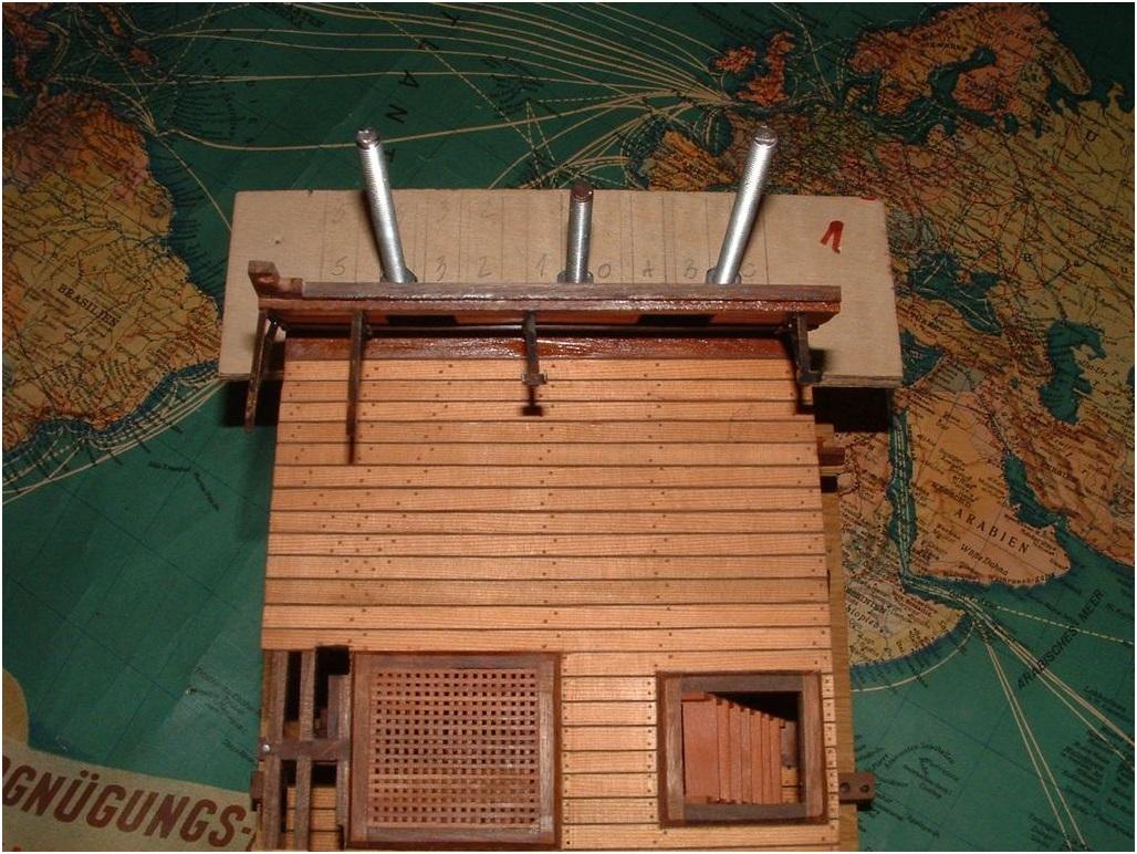
but now to the used jig!
It is basically the way which is shown in B. Frölichs book THE ART OF SHIPMODELING and described here in principle with this sketches
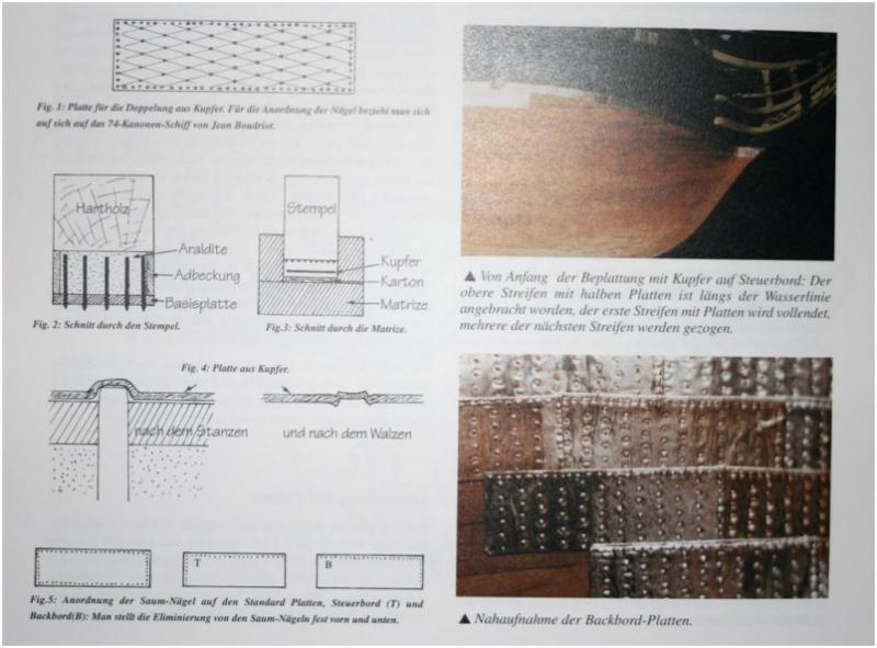
Fig1: The pattern of the nails
Fig2: The stamp or plunger (punch)
Fig3: Cross-section through jig with copper-plate and stamp
Fig4: Detail of the copper-plate after punching and on the right side after rolling
Fig5: Pattern of the nails at the edges (overlaying)
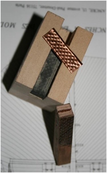
If you look at the right bottom photo you see how it should look like and what is possible to make, if your name is Frölich
Here is a photo the actual used jig (which was made by Zeljko and given to me for my works on the section)
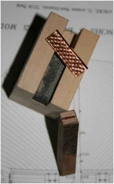
inside is used a hard rubber and no cardboard like proposed by Frölich
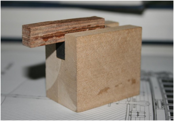
the stamp pressing the copper-plate
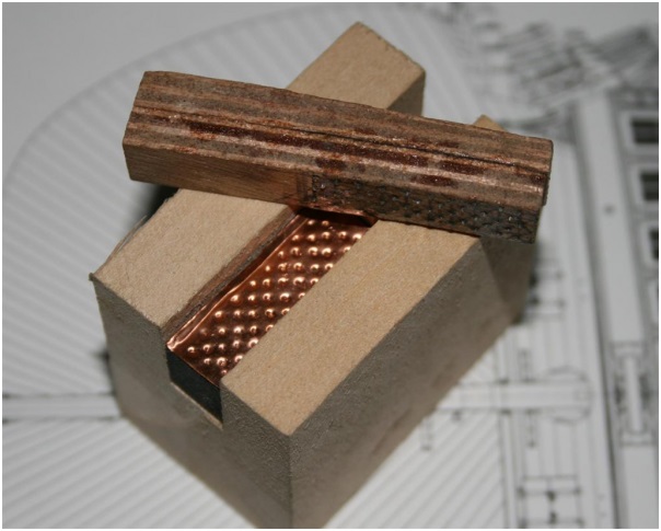
here you can see the small ends of the nails in the stamp
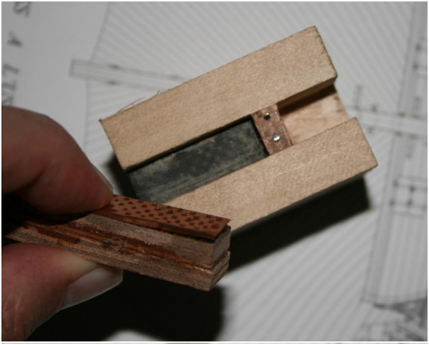
the copperplate on top of the stamp
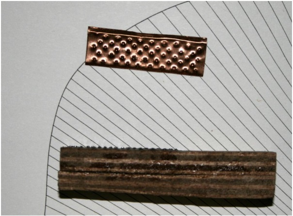
close view - you can see the nail-ends
And?
Chuck, is this the same kind of jig or tool you are also using?
Questions, Comments etc. welcome......................... -
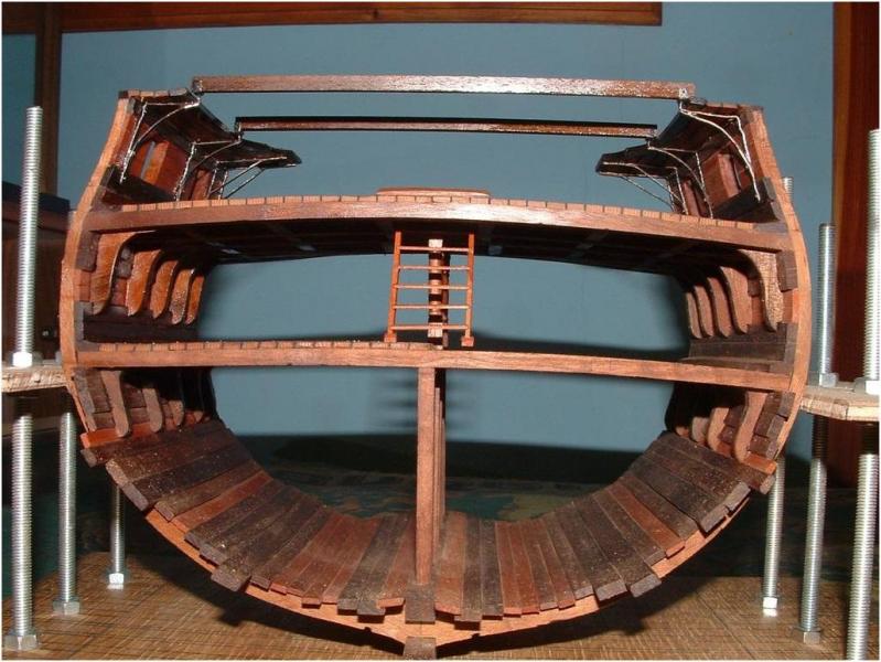
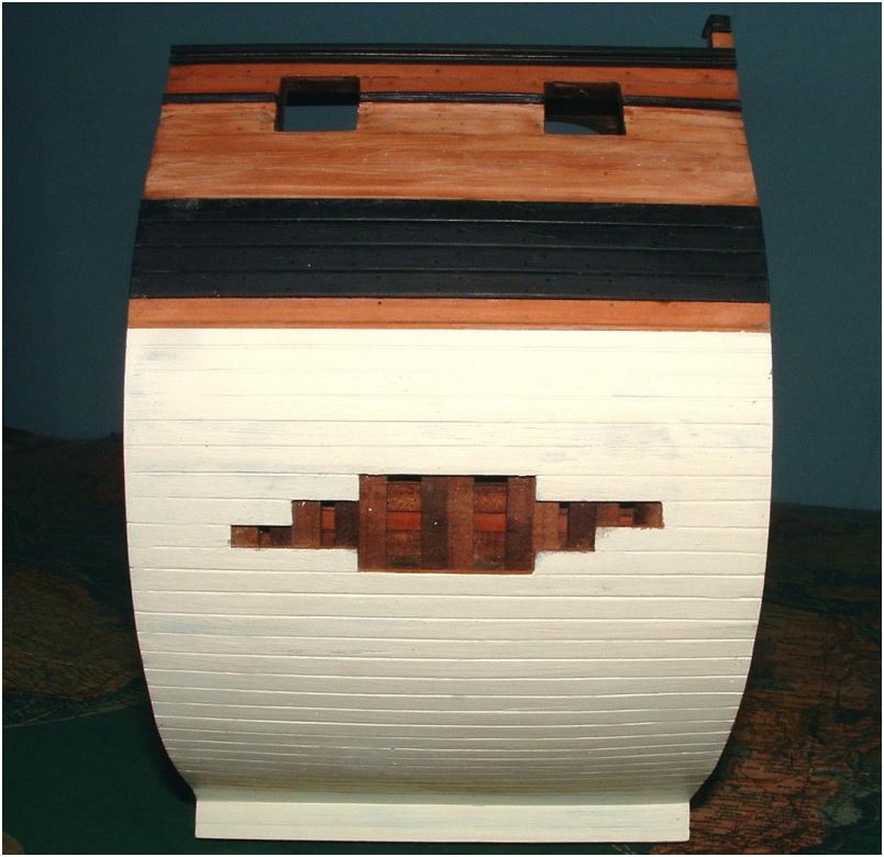
Some days ago I could show the hull of the section with the white stuff and the "window" with un-planked area covered with white stuff.
As we learned in an other topic the Triton hull was in the beginning covered with white stuff and later on coppered:
...............and noticed in the Winfield extract that Triton was "refitted and coppered at Chatham" Feb-Apr 1779.
Based on this information the idea was born (thanks once more to Zeljko), why not show one side of the section model in the early version (from launch until 1779) with white stuff (see some posts before) and on the other side the later version of the Triton after the refitting in 1779 with coppered hull:?:
In addition you see every time only one side of a model and everybody can decide which one is the "Chocolate-side"
Here is the result showing the "other side" of the section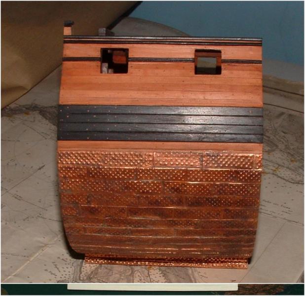
-
Hallo Russ,
the used paint are the standard paints from the producer "REVELL", these are synthetic resin enamel paints
Revell Enamel Paint - White
I have also good experiences with the enamel paints under the name Admiralty Paints offered by Jotika,
once I want to try also the waterbased paints of the same producer!
Maybe somebody has already some experiences with this kind of paint
Usually the matt white with a little bit of yellow or ochre, in order to get the "little bit dirty"-finish of the White Stuff !
Two levels of paint (because of the better cover) and a last finish with some steel-wool to get a smooth and clean surface with a fine brightness. 8)
-
Hallo Bob,
thank you very much for your kind words about the shown work and the way of showing the work.
For me and also for my "personal" mentor Zeljko is the difference of modelling and in background the salt in the soup of our hobby.
Have a look at the different Section models here in MSW, everyone is special, different and partly individual. 8Partly based on the use of different timbers, oil or color, scale, techniques and and and........And this makes our hobby so interesting and we all have all a lot of fun.
Especially here with the Triton, which brings a lot of fun.
Now a short first photo of the hull-side with the "window" painted with "white stuff"
-
ZZ:
I do not know how Uwe cut his gunports after framing the hull, but that is definitely what we call an "alternative" method for framing the hull. It appears to have worked out okay, but I would not recommend it as it falls well outside the scheme of the plans that we drew to for this model.
We designed these drawings to work in a certain way and it is really best if you use the drawings as they were intended because it gives the builder as much information to work with as possible. In the case of the gunports, we placed the marks for the sills and lintels on the assembly drawings so these could be marked and then cut out while the frame is still flat on the drawing and in the assembly jig.
Those assembly drawings were designed with the top reference line and the bottom reference line so an easy to make, adjustable assembly jig could be used to ensure that each frame was properly sized and that all the marks for the deck beam clamps and gunport sills and lintels could be transferred right from the drawings. I went over this assembly jig in an earlier post.
Ideally, (and I strongly recommend this method) the cut outs for the sills and lintels should be made while the frames are still on the assembly drawings. By doing it this way, you can use the assembly drawings to make absolutely certain that the cut outs for the sills and lintels are properly placed. With the frame in its assembly jig, the entire operation can be controlled to achieve maximum accuracy.
It is much much more difficult to do the cutting accurately after the hull has been framed since the cut outs must still be double checked with a vertical measurement from the plans to ensure they are properly placed. It is possible to do this, but it is much easier and more accurate to perform this operation with the frames flat on the assembly drawings.
Russ -
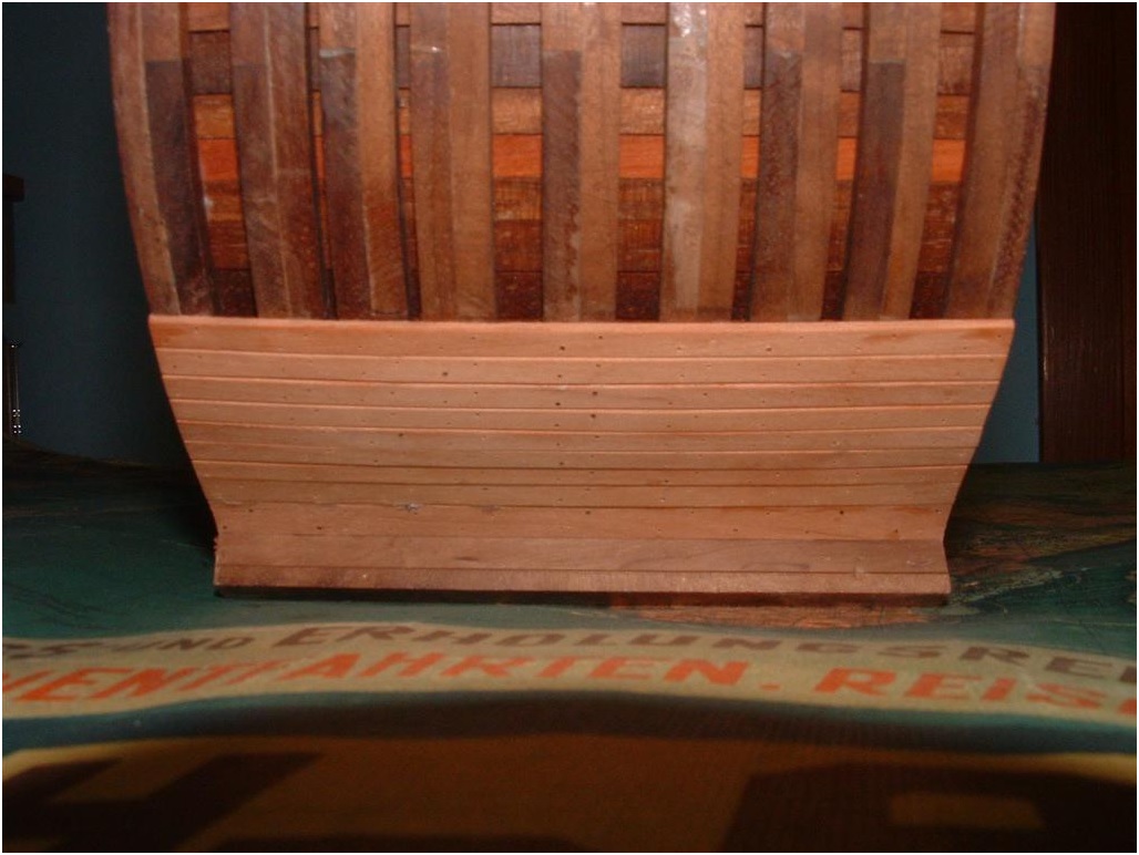
The planking is going on! after the installment of the wales starting with the hull planking from the keel, similar on both sides, with the same width of planking stripes.
A little bit glue coming out between the planks will be sanded "away". It should not happen but sometimes it happens!
In order to show the interesting framing of the Section a small window which is making them in a smaller part visible.
The edges of the planks in longitudinal direction are a little bit cut (sanded) in order to see afterwards (white stuff) each plank.
-
Thanks Alan! - it does look like I have missed judged the height if the rising wood. On my plan the bearding line is the third one up on the left.
I can go back and work out where I went wrong now and adjust.
Thanks for the course correction

Joss
-
Great idea - better to decide before hand than to slap on some stain/other and then decide you prefer something else
Joss
-
That looks like Holly, are you caulking? or going for a pure look..
Joss
-
Nice, have you considered whether you are planking the entire deck or just a section of it??
Joss
-
-
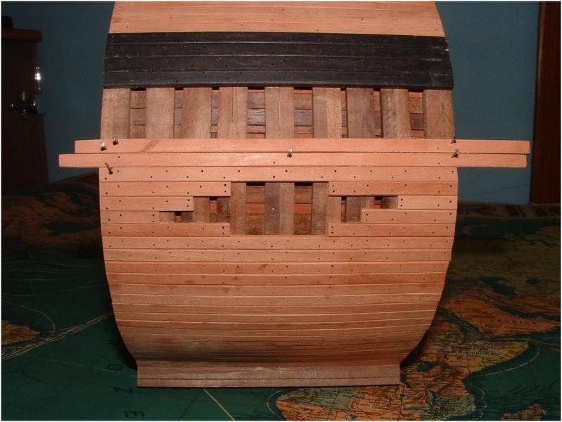
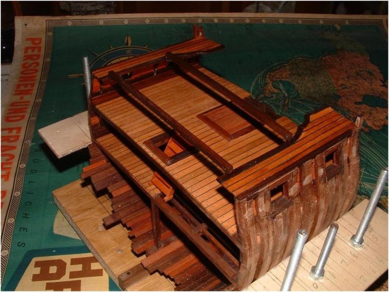
ZZ started the talk about the outside planking especially the wales in anchor-stock pattern,but this decision I leave open for me (and everybody else) for the complete model.
Here the next photos of the building log with the first top levels of the outside planking with the two Trim moulding, installed Sheer Rail and the Wales.
You see a plank temporary installed over the gun-ports for preparation of the cut.
Also installed the four wale-planks. Also visible are the drilled holes for the treenails.
These planks are installed every time similar on both sides of the hull, so the sides are as much as possible mirror-inverted and identical, especially if you follow the planking down to the keel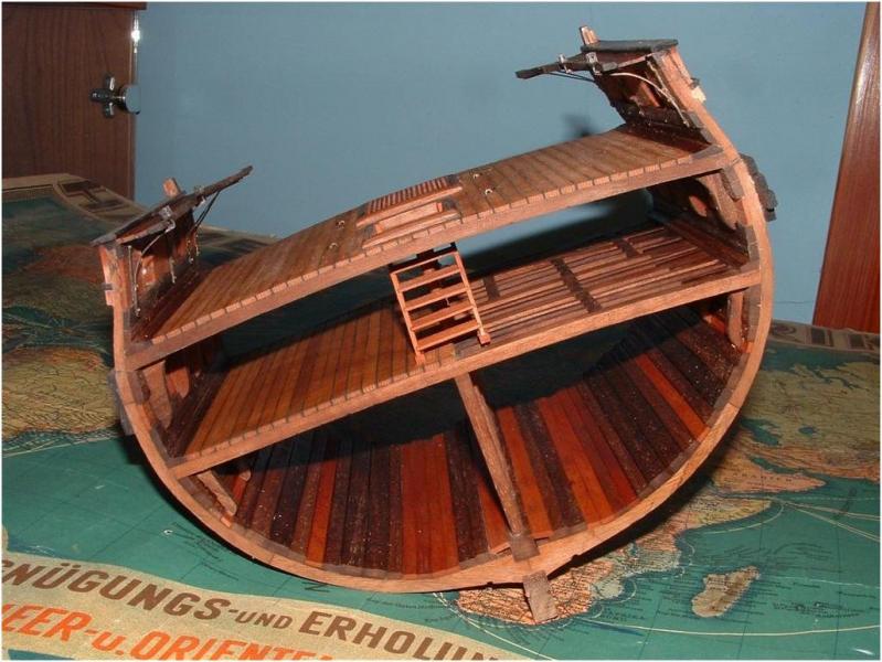
-
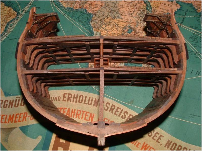
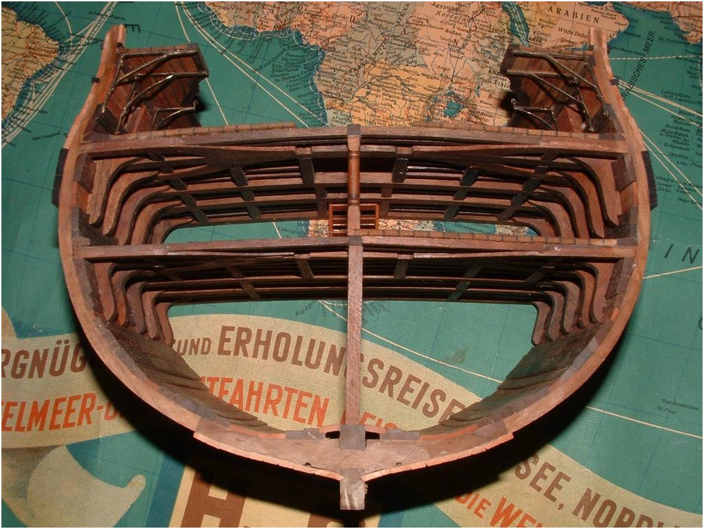
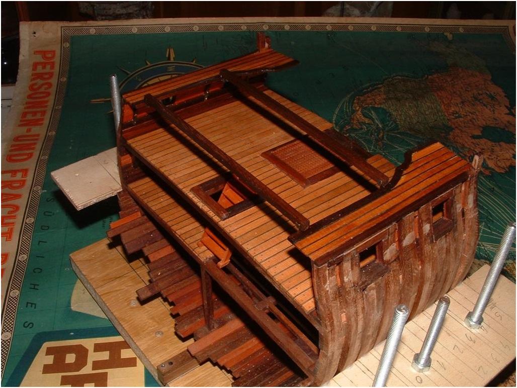
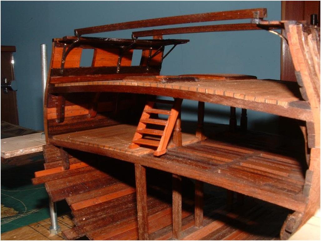
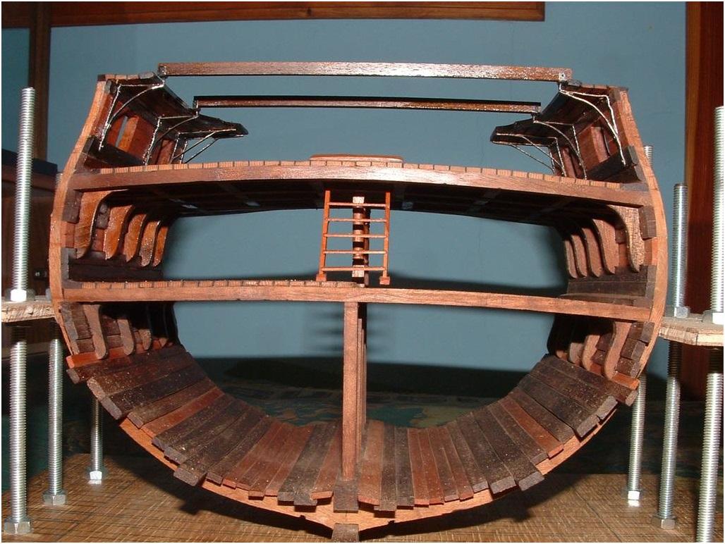
Back to the building log of the Section:
The Gangway is (dry)-installed on top of the brackets and the two Skid beams are laying on top of the crutches (also dry).
Please be aware that the timber was freshly oiled therefore the shiney surface.
Photos were made extra from different perspectives in order to see this part better.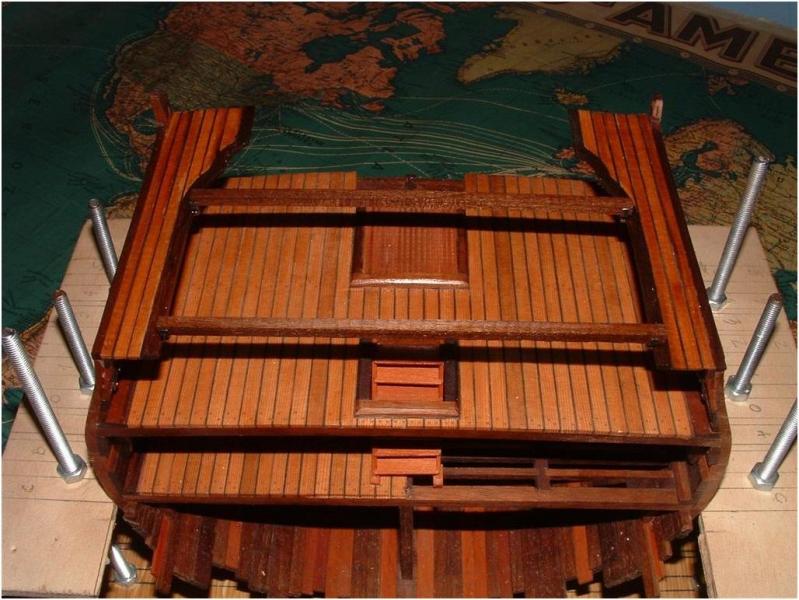

Please have in mind that the Skid beams have no camber!
-
Uwe:
Your sequence of construction may work out fine, but it does not necessarily take into account the unforeseen need to make slight alterations in the position of the gangway bracket that is second from the last nearest the gunport. It would be much better to get the eyebolts positioned before that bracket is mounted. And, it is just much easier to get all the eyebolts positioned before any of the holes for the brackets are drilled.
The logical sequence is to get all the holes drilled for the eyebolts, then place the guns in position to note where their tackle will be located, then you can place the gangway brackets and drill their mounting holes. Then remove the brackets, mount the guns and rig them, and then you can mount the brackets. That is the path of least resistance in the construction
process. We must keep in mind that inside the hull, we are working from bottom to top.
As for the bracket color, it is a matter of taste, but I highly recommend completely blackening those brass pieces as it is easy to do and creates a much more historically accurate look to the entire model.
By the by, I would also highly recommend hand drilling those holes for the eyebolts and the brackets. A power drill can easily get away from you in such a confined space. I know a lot of builders use power drills for this sort of thing, but please consider a pin chuck or twist drill to do that kind of fiddly work in a confined space.
Russ -
Uwe:
Okay. That must be one very powerful flash though. It looks like bare metal.
As I wrote already before.....they are not completely black....I prefer by myself (question of taste) the look of old brass and not the pure black iron.... it is than a weathered look! You will see this also later on at the gun-barrels.And if you compare the bare metal photo (therefore I copied already before the photo showing the bare metal brackets from the old post in order to compare) than you see ( I hope) a difference, especially in the photo No. 2 showing them from the top (which I also mentioned).
You will see in future photos that they are blackened! 8)
Another question. Will you be able to mount the eyebolts for the guns with
the brackets in the way? Ideally, I would recommend all the eyebolts in the
bulwarks be mounted before the brackets go on. In fact, the brackets might
ought to be the last items to go right before the actual ganagways are
installed. They will be in the way of mounting and rigging the guns.
Russ
Due to the fact that the eye-bolts are on the height of the lower edge of the triangle of the brackets (see here your plan "tackles") I see no bigger problem to drill carefully small holes with the hand grip of the proxxon.
If the location of holes would be higher I would fully confirm your words, but here it is possible without bigger problems.
To install and rig completely the guns before the installation of the brackets?
But definitely I would drill all necessary holes for the brackets before all these installations, because I think that than it will be not possible any more to drill or minimum you accept the risk of destroying installed parts during the drill-action.
You are completely right that the modeler should organize and plan in which sequence some works have to be executed.
But sometimes you look at it (your model) and you say by yourself "SH..."!! -
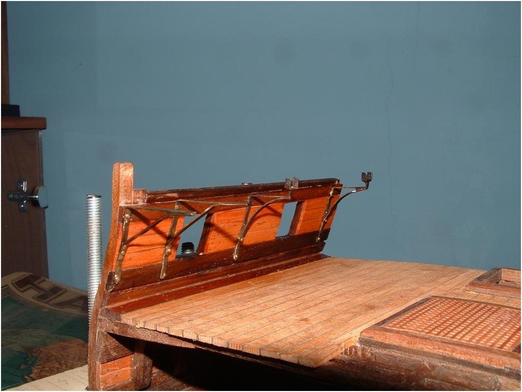
In order to remind you about the last status of the building log, this was the last post showing the prepared Support brackets.
Now they are installed

-
Hallo ZZ,
with the paint it is also working.....I use this method usually for the thin planks of kits glued on a false deck.......painting one
side with a black "marker". I am usually not painting both sides, than the caulking is getting to thick for the scale.
Only one tip: Try it before at an example.....some wood, especially soft wood is sucking the paint into the grain and this you will see. Too much paint on the top can be usually removed with a little bit sanding.
Therefore make a dry run at an extra sample piece.....and can try also using the "paper-method".....afterwards you will know which method will be for your model (and your kind of timber) the best


UWEK Triton Build (re-post by mod)
in Cross Section Build Logs for HMS TRITON
Posted
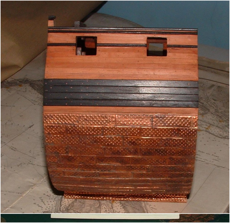
Hallo friends,
after this longer excursus to the (surprisingly) wide subject of coppering,
let us go back to the construction of the Section model.
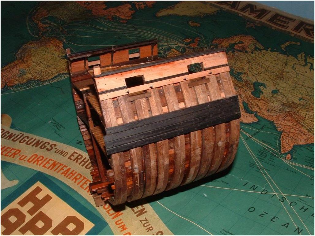
Here you see the coppered side (for everybody not following this building log the other side is not coppered,
but covered with "White stuff") with the installed Trim Mouldings (Outboard Trims) and the Entry Steps.
And here in addition the two fenders
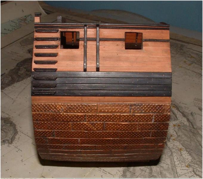
And with a closer view where you can see some smaller negative points which you sometimes see first with the closer look through the camera-objective ......a little bit rest of glue at one or two steps (can be removed)
......one step (third from top) is not completely in level (**** )
......and one fender is a little bit split (can be filled carefully).
Special Remark:
For all others members who build also the Section model, please
do not forget the post of Russ regarding the entry steps
The second step from the top should be on the same level like the lower trim !!!!