Doc Watson
-
Posts
39 -
Joined
-
Last visited
Content Type
Profiles
Forums
Gallery
Events
Everything posted by Doc Watson
-
 The dockyard foreman caught a workman trying to steal some grog and put him in jankers for a week, either that or someone has had a bout of flu!?!?!. Just about recovered and some progress with the ships lanterns which should be done by next week and I finally have a plan for the rear of the boat.... cutting wood as we speak. Avast me hearties!
- 29 replies
-
- 6
-

-
- Fly
- Victory Models
- (and 1 more)
-
Effect in the ship.... I think it looks convincing.... Lantern01.mp4 Avast me hearties!
- 29 replies
-
- 3
-
-
- Fly
- Victory Models
- (and 1 more)
-
LED light inside the ink tube of a bic pen..... Lantern03.mp4 Avast me hearties!
- 29 replies
-
- 1
-
-
- Fly
- Victory Models
- (and 1 more)
-
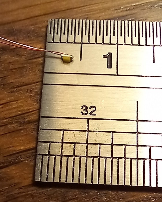
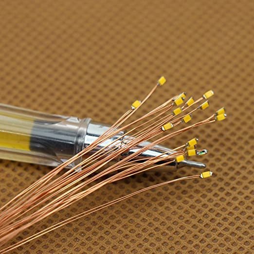
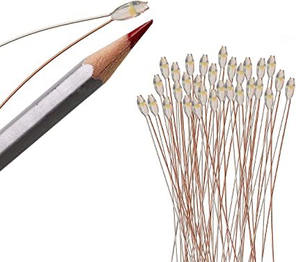
The LED lights have arrived and have been tested!!! They are small enough (I think) to use as candle lights and a quick program using an Arduino proved the flickering effect, the light is a little to 'white' but am experimenting with resistors and 'filters' (by filters I mean a light wash of oil paint on the LED) to soften the colour. The wire is 0.1mm and insulated with a coat of something (clear lacquer or plastic?) which has to be scraped off with fine sandpaper. Should be no problem replicating a lantern and the wires are 20cm long to allow each light to be located and the wires fed into the lower hull where they can be then soldered to 'more substantial' wire which will then be passed through the keel into a display 'box' holding the Arduino and batteries to run it. I also had a horrible idea of adding a real time clock, mp3 player module and speakers in the shallow box display base and the Arduino would use the clock to ring out the bells every 30 minutes, a sort of maritime clock. 8 bells!!!!! end of watch! Avast me hearties!
- 29 replies
-
- 3
-
-

-
- Fly
- Victory Models
- (and 1 more)
-
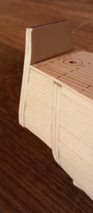
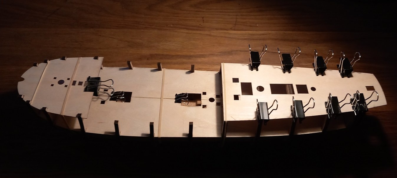
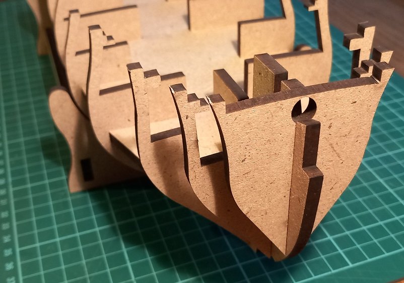
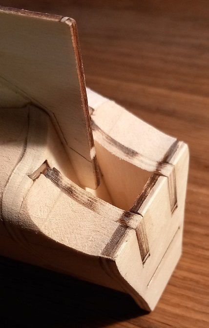
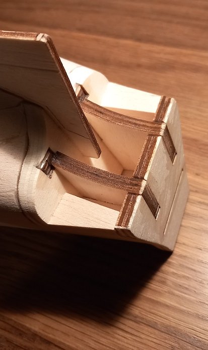
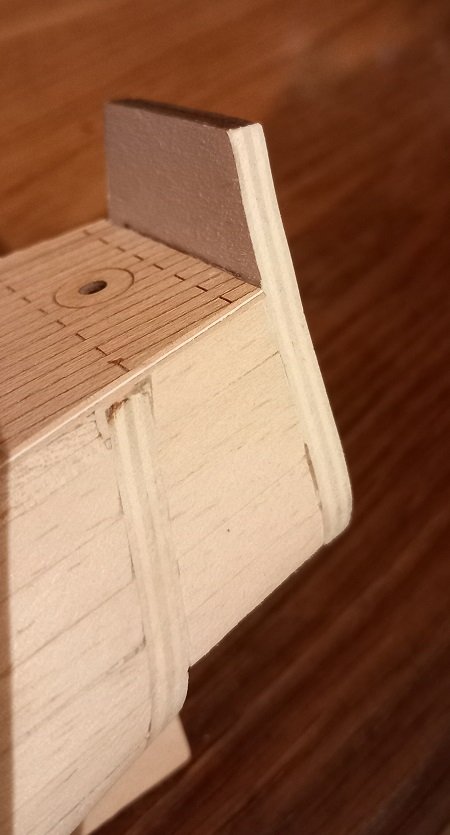
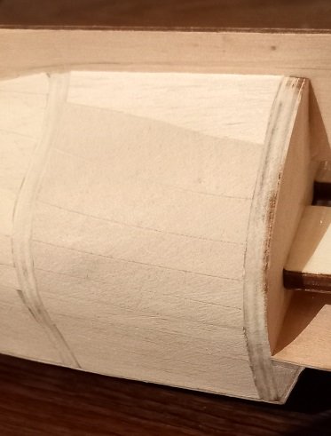
The transom assembly from the kit...the gap is to be planked. I notice that Blue Ensigns window was walnut sheet. I decided to dry fit the decks and the beams, remembering to widen the deck slots for frame 12. Decks fit very well. Avast me hearties!
- 29 replies
-
- 9
-
-
- Fly
- Victory Models
- (and 1 more)
-
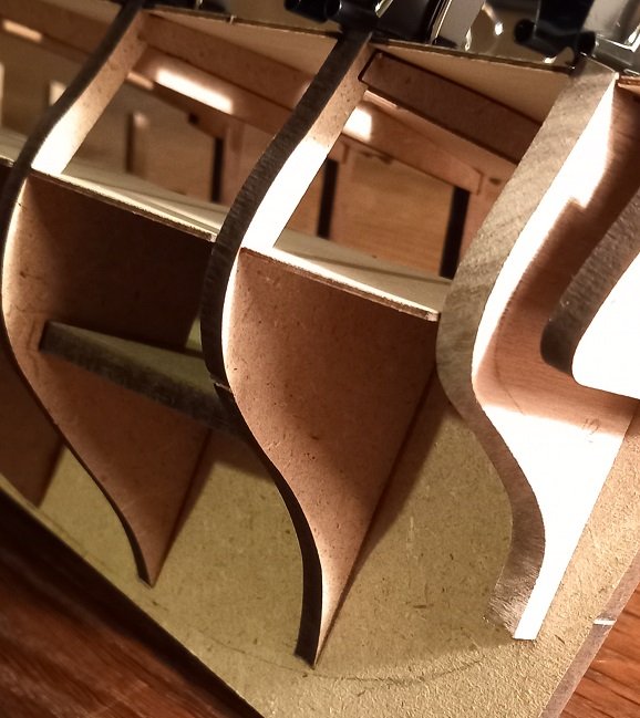
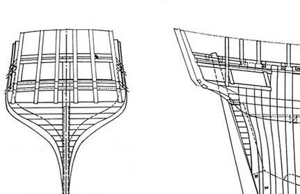
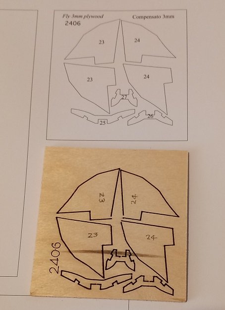
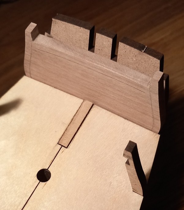
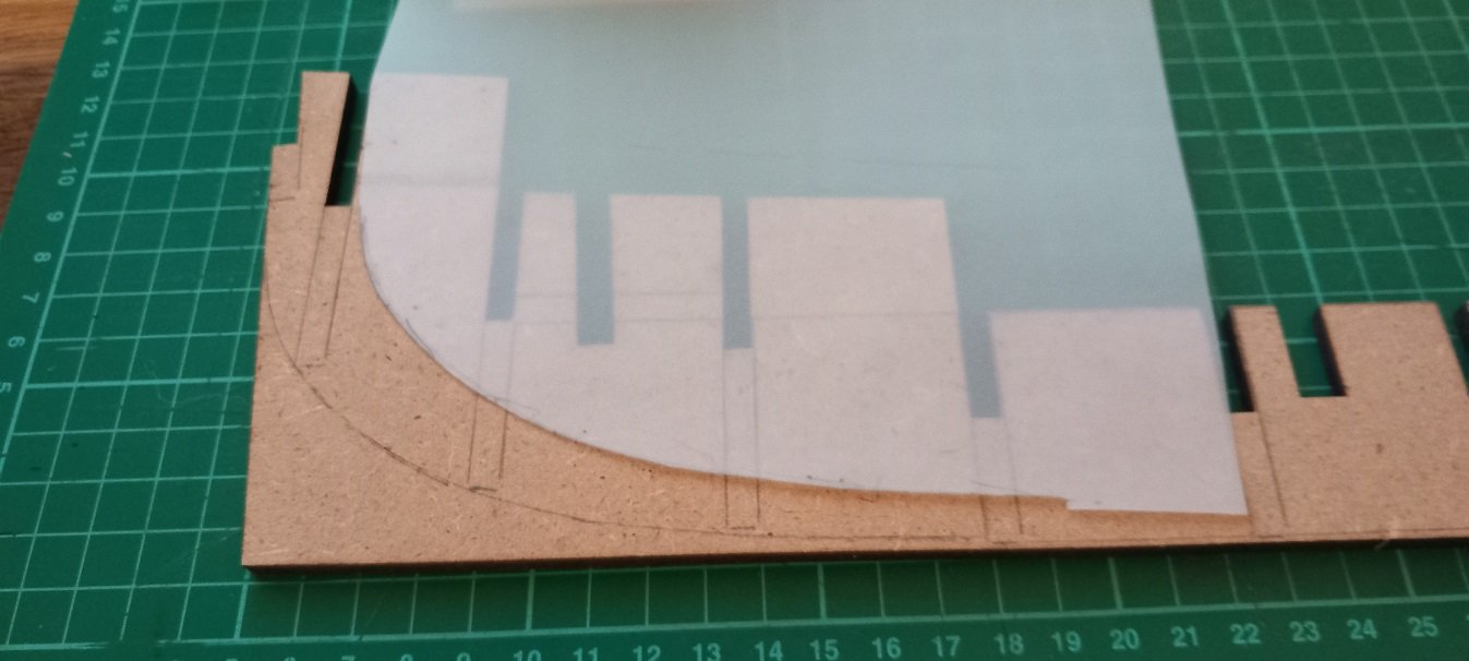
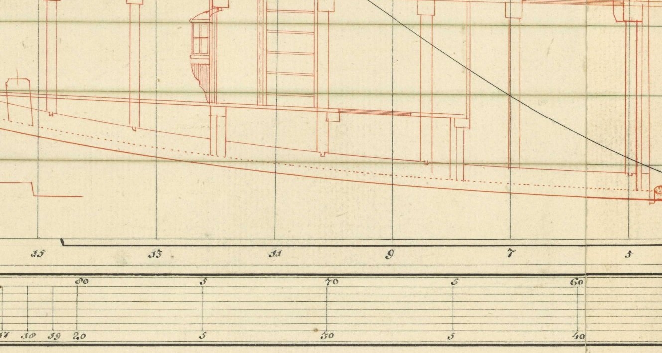
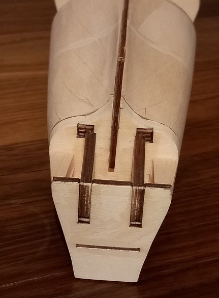
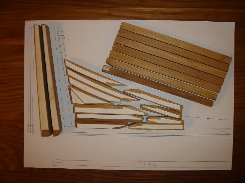
Thanks SpyGlass, not only do the outer pieces need to be inline with the deck which curves on top and the angle of the deck viewed from above but the rear also has a curve. I'm going to make 6 transom frames as shown below. (plans from HMS Bounty) each frame will be 3mm walnut (what else would it be!) and will sit between the window frames of the transom. Not sure about the horizontal framing yet. Avast me hearties!
-
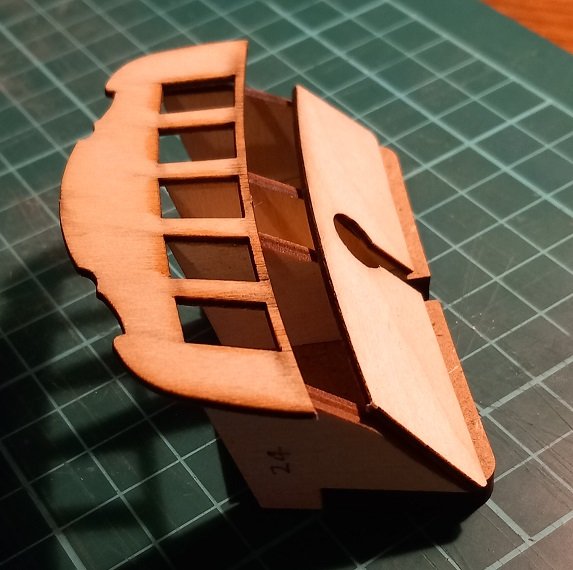
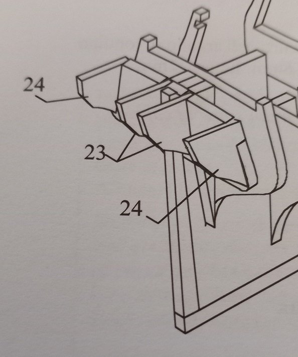
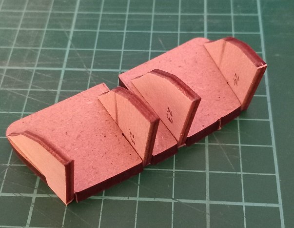
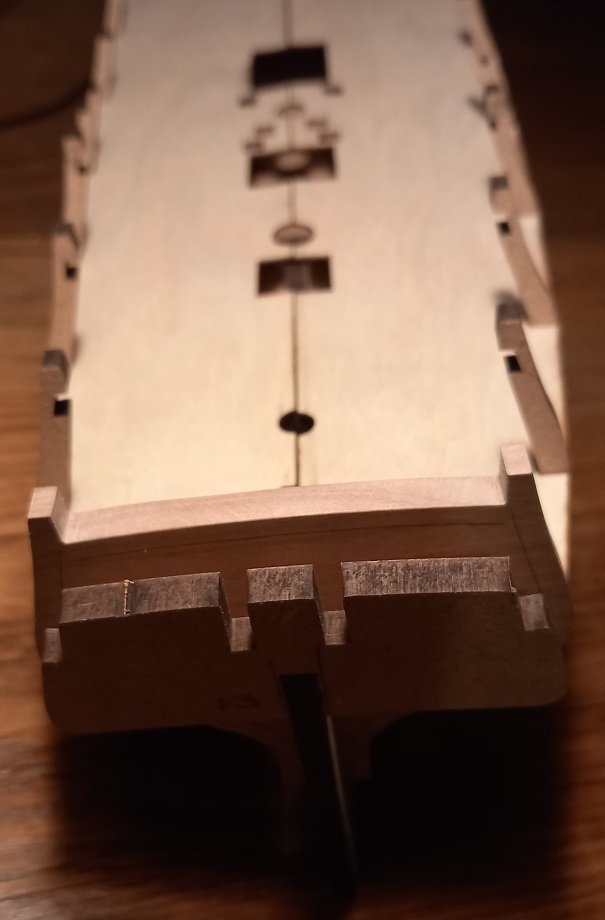
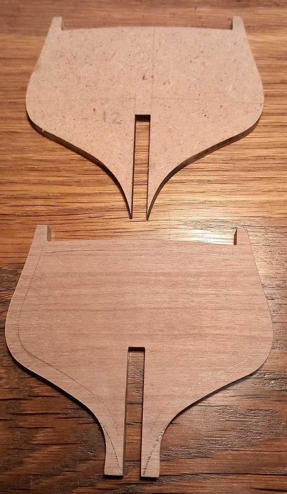
Frame 13 has 4 plywood pieces which form the transom area. Parts 23 and 24 look very similar so marked them... ...and dry fit on frame 13. Still thinking about how to open up the cabin area here. Avast me hearties!
- 29 replies
-
- 3
-
-
- Fly
- Victory Models
- (and 1 more)
-
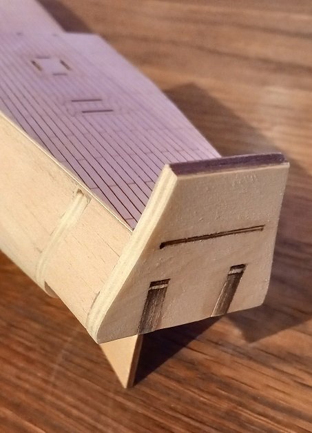
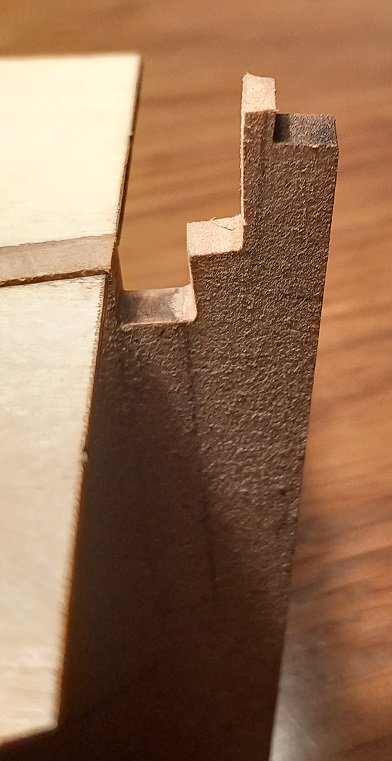
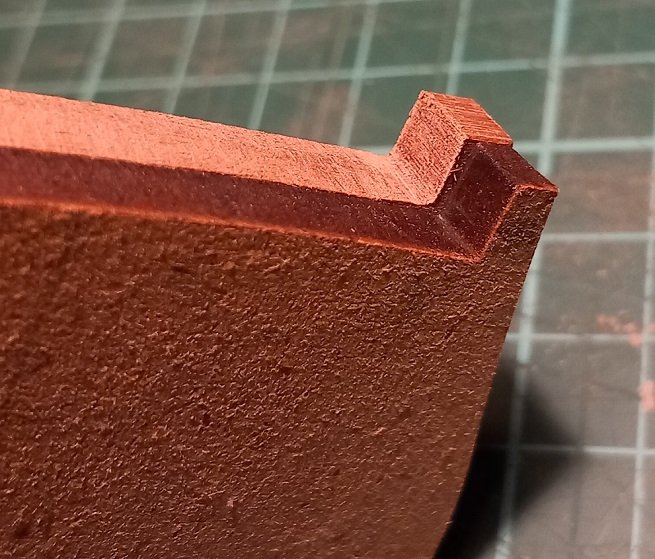
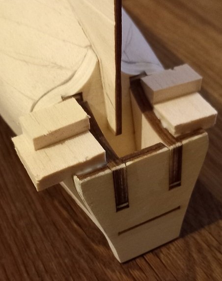
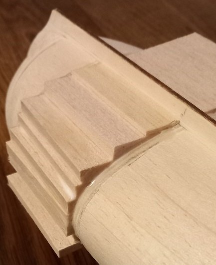
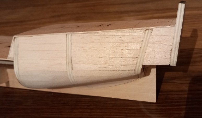
Cut the keel around the captains cabin and reassembled to mark the deck level on frame 12. Frame 13 is a little wonky! not a sniff of glue anywhere! And ready to mark the deck line on walnut frame 12... I have left the cut MDF slightly proud of the deck to be faired later after gluing the frame assembly together. And below is the cut keel with 6mm width for frame 12 and a 'step' was left for location of frame 13. I now need to study plans and decide how to extend the rear of the hull to the transom, a new walnut frame 13 is calling from across the waves. Avast me hearties!
- 29 replies
-
- 1
-
-
- Fly
- Victory Models
- (and 1 more)
-
SpyGlass, the MDF frame 12 has the deck height marked on it, I haven't marked it on the walnut part yet and will probably do it with the frames and deck assembled. After all that cutting I must have gotten a little carried away. Avast me hearties!
-
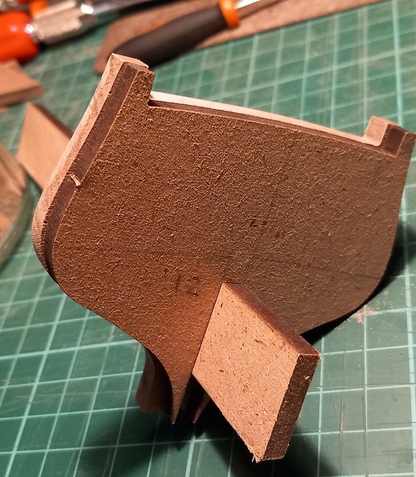
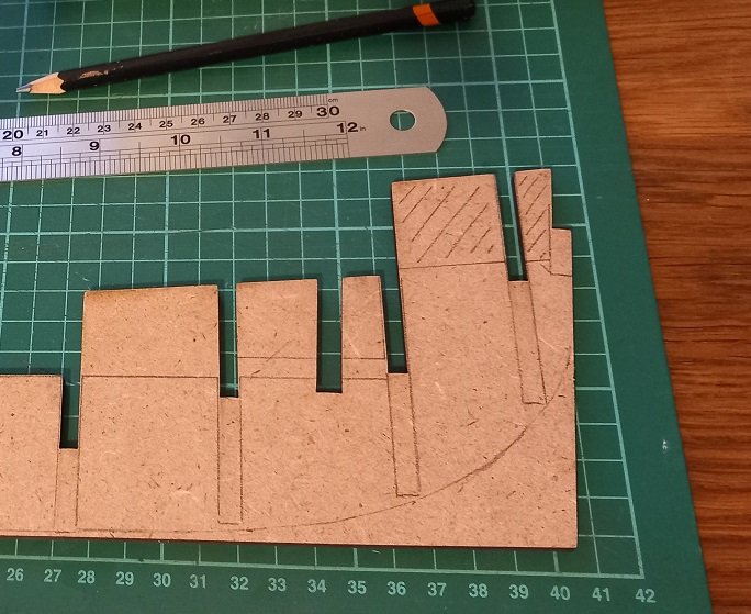
Finally..... Also marked 4mm inside lines for removal but a dry fit on the keel is required first. I also need to chamfer the edges and will delay removal of the inner section until I know how much bevel is required. Avast me hearties!
- 29 replies
-
- 2
-
-
- Fly
- Victory Models
- (and 1 more)
-
allenyed, again thanks for the information but as its so low in the ship I wont be lighting (or modelling!) below the MDF 'deck'. DavidG, got them here... https://www.amazon.co.uk/dp/B08ZH98BRJ?psc=1&ref=ppx_yo2ov_dt_b_product_details Will have them tomorrow and will test them. Finally got the slot for the keel filed to size. I used a piece of the 'waste' MDF as a guide and PVA'ed some 600 grit paper to one edge to get the end of the notch square. Now the slot is done I can clamp and file to final shape. Avast me hearties!
- 29 replies
-
- 4
-
-
- Fly
- Victory Models
- (and 1 more)
-
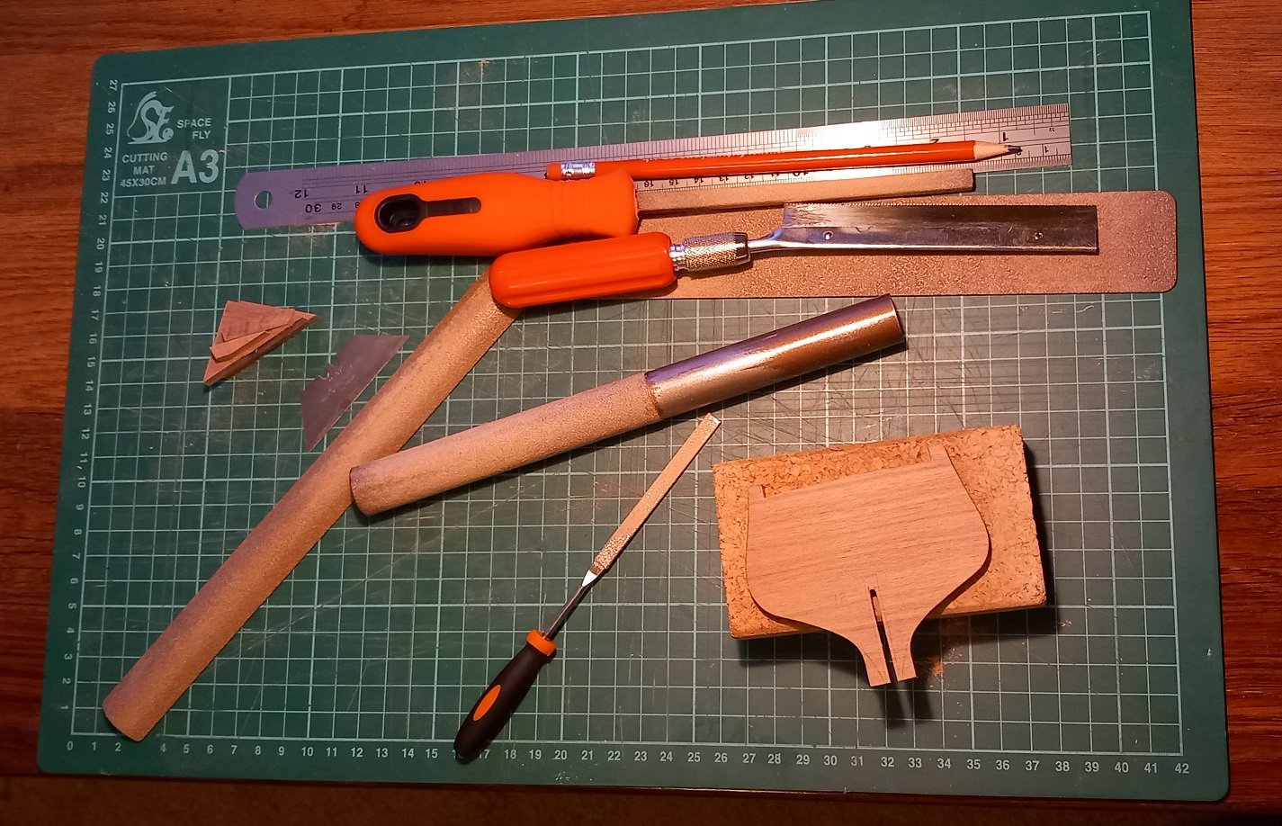
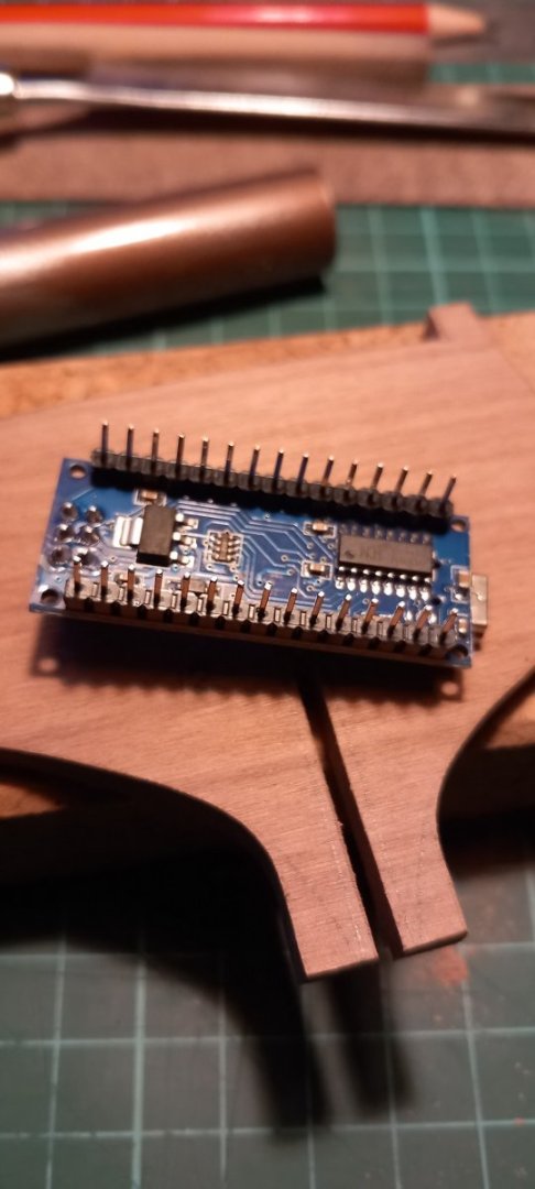
After a few hours... getting there... Once the keel slot is cut to the correct size I will start modifying the MDF keel piece and plan the cutting of the 'inside' of frame 12. Walnut is hard and the only power tool available in my workshop is the Mk I human body. By workshop I mean an A3 420mm x 270mm cutting mat with a rule that all tools/parts must only be on the mat! LED lights ordered and arriving in a few days. 10 of each for testing. hope there small enough!!!!! both 'warm white' in colour and I will control them with this.... Its an Arduino 'nano' clone which can be programmed to supply voltage to the LED's at a frequency of about 500Hz. I will start designing an LED lantern first, should be fun simulating the flicker of a candle. Edit: Quick google later and a candles frequency is anywhere between 5 and 12 Hz... Avast me hearties!
- 29 replies
-
- 6
-
-
- Fly
- Victory Models
- (and 1 more)
-
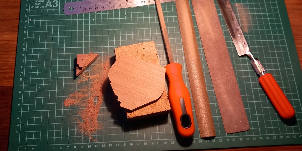
I'm finding out that walnut is as tough as... nuts.... I wish I has a scroll saw, but micro saw and Perma-Grit 'fine' sanding collection will see me through for the moment. The sawdust will be saved to make walnut filler if and when required, good job to as I'm making loads of it. I must also say (if I may) that the fine sanding tools are a joy to use and come in a selection of shapes. I will have to be careful when sanding bevels as the walnut is much harder than the MDF (and of course balsa) but with the MDF being 5mm thick it is very strong. I could have used the MDF frame 12 of course but just love the smell of cut walnut! Avast me hearties!
- 29 replies
-
- 3
-
-
- Fly
- Victory Models
- (and 1 more)
-
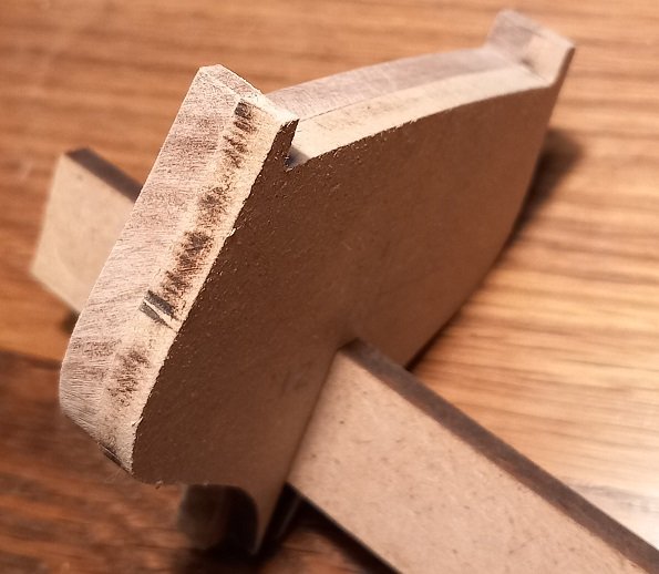
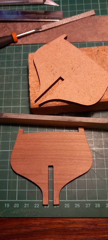
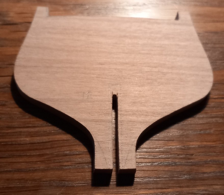
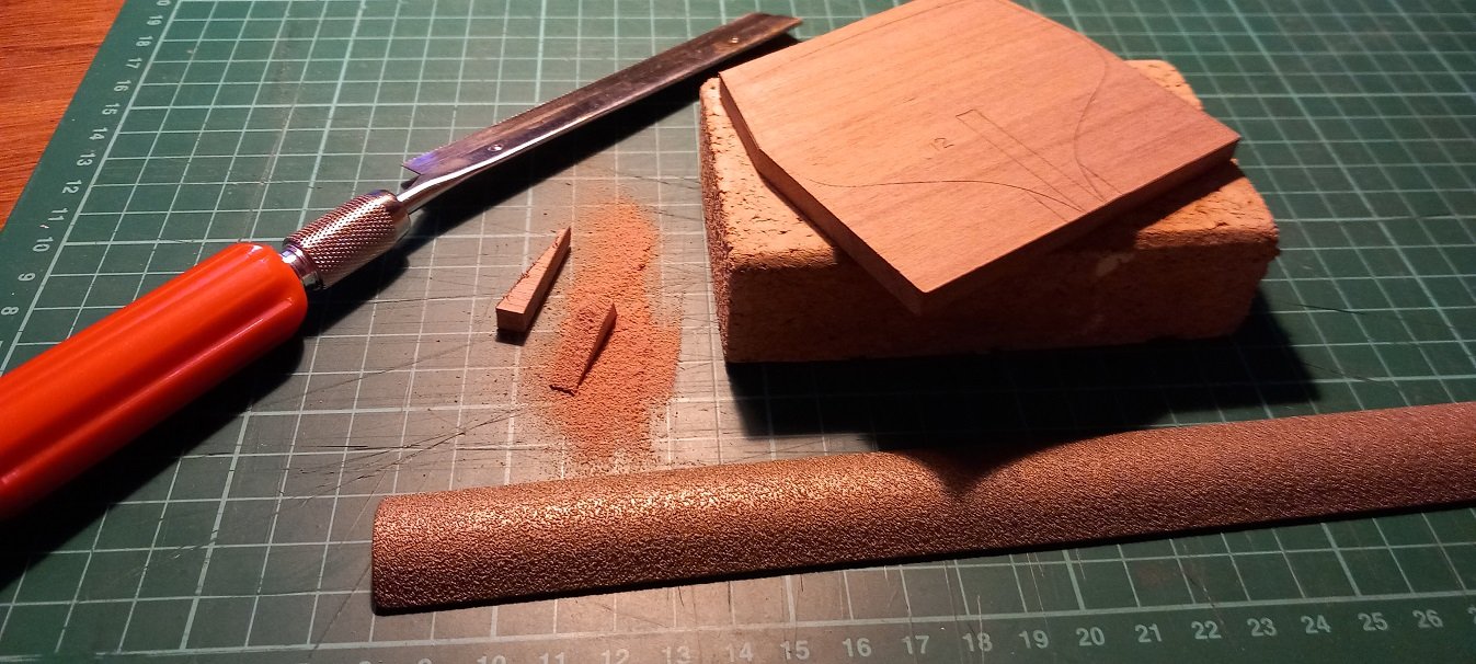
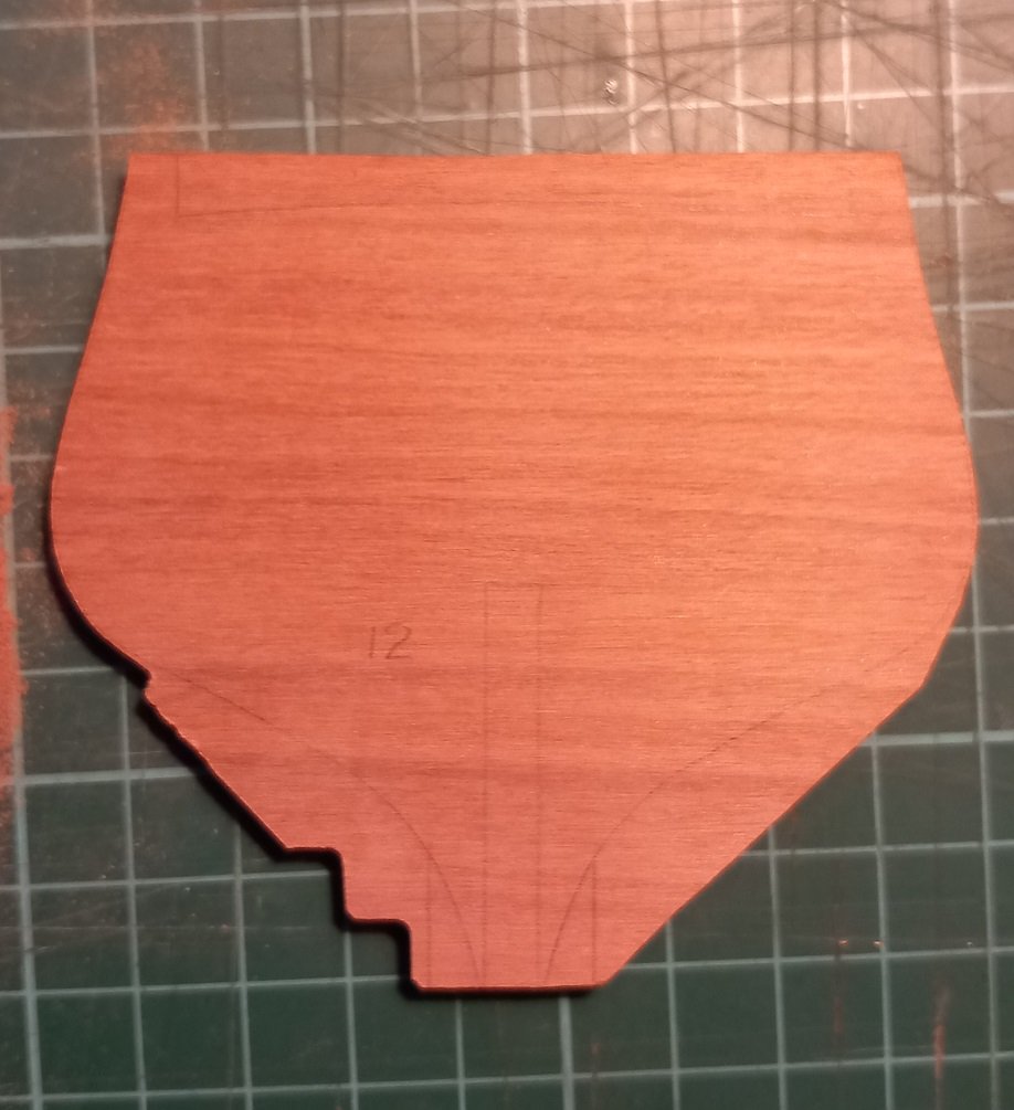
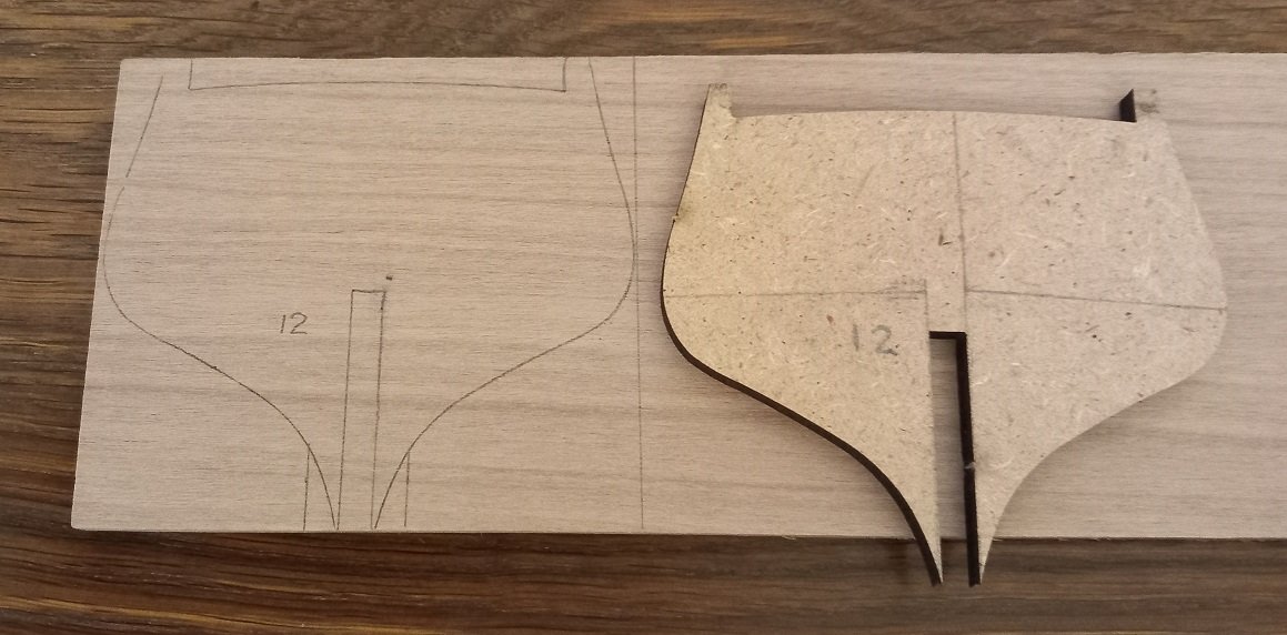
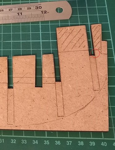
I have some 6mm walnut sheet which will be used to fashion a new frame 12. I would have preferred to have the grain running vertically but the sheet isn't wide enough so I will be leaving a 5mm strip where the frame meets the keel piece. This will be sanded back once the frame is glued to the keel and blocking added between frames to (hopefully) prevent any breaks Once the outline is cut out I will mark the area inside the frame to be removed. To accommodate the extra 1mm width of the walnut a small amount of the keel slot will be widened, shown by the red circle. Now where did I put that micro saw...... Avast me hearties!
- 29 replies
-
- 3
-
-
- Fly
- Victory Models
- (and 1 more)
-
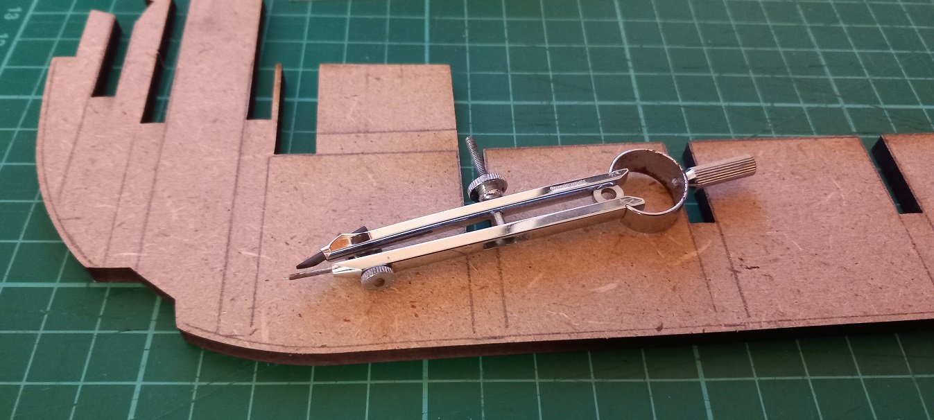
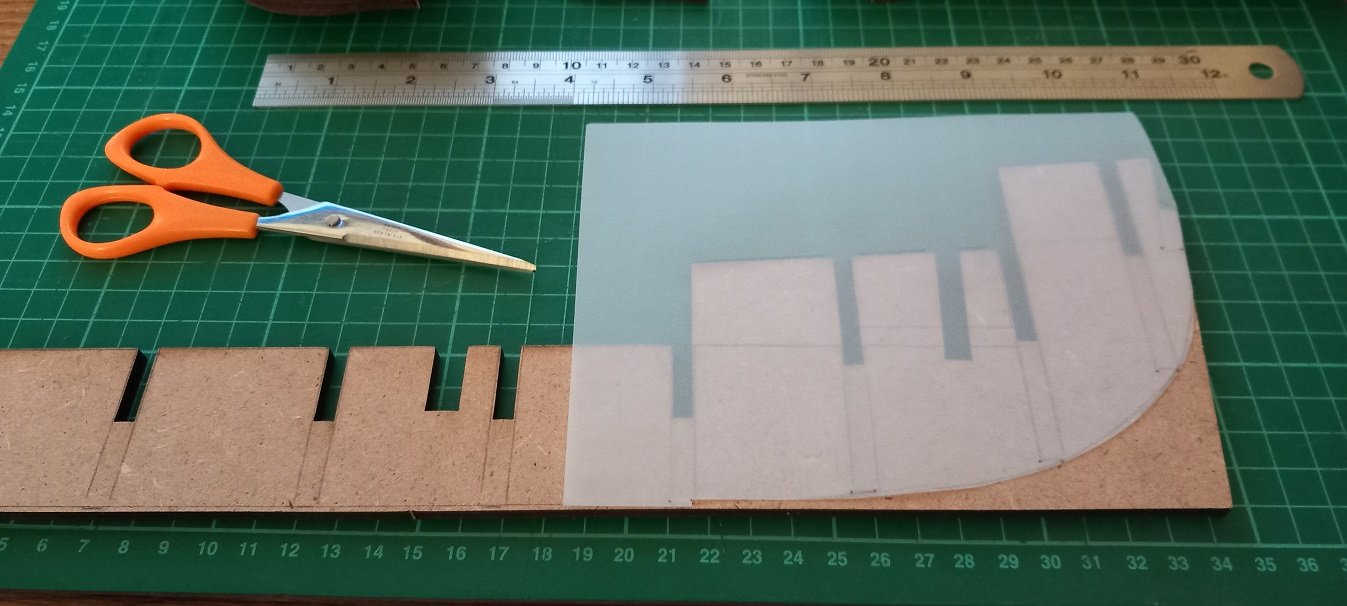
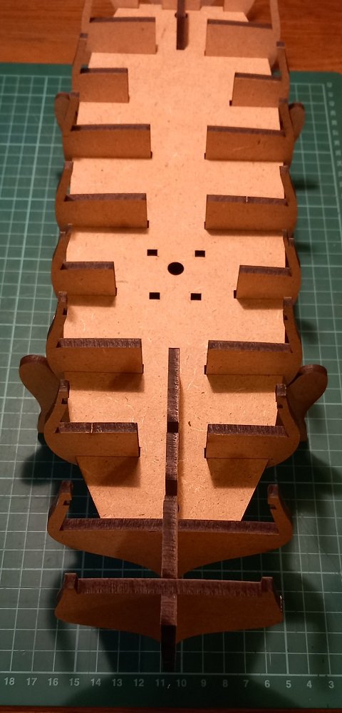
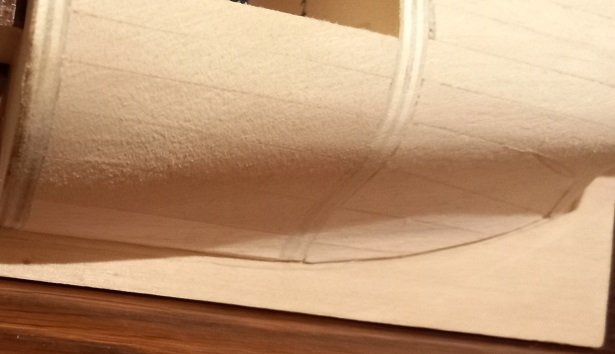
SpyGlass, I have the 2 piece ply deck and haven't closely looked at the castings yet. I trial fitted all the decks and they fit very well with only a little 'tightness' where the two pieces meet around the stern. Easily remedied with light sanding of the frame notches. So I marked the keel with all bulkhead positions and disassembled. I then took my old (we are talking 1960's) drawing set and used a compass to mark 1.5mm above the keel for the rabbet line. Notice the compass pin is extended to allow it to drag along the keel. The bearding line was created with a piece of tracing paper placed over the stern and a line drawn followed by cutting of the tracing paper. The bearding line can then be traced around (the tracing paper!) on both sides ensuring accuracy. Note the 1.5mm notch for the rabbet at the bottom. And finally the stern keel has marked for removal the area which would protrude into the captains cabin. Next I will ponder a new frame 12. Where did I put me Walnuts? Avast me hearties!
- 29 replies
-
- 3
-
-
- Fly
- Victory Models
- (and 1 more)
-
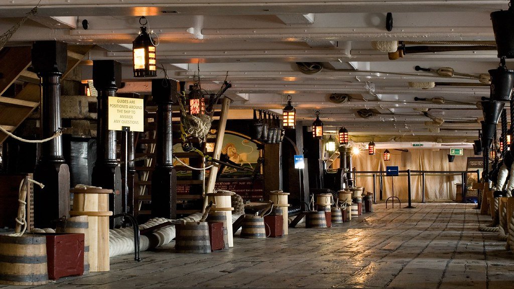
Allanyed, thanks for the information I assume the magazine light room is this... And a quick look at HMS Victorys gun decks also shows the location of the lights. Food for thought... Avast me hearties!!!!!!!!
- 29 replies
-
- 1
-
-
- Fly
- Victory Models
- (and 1 more)
-
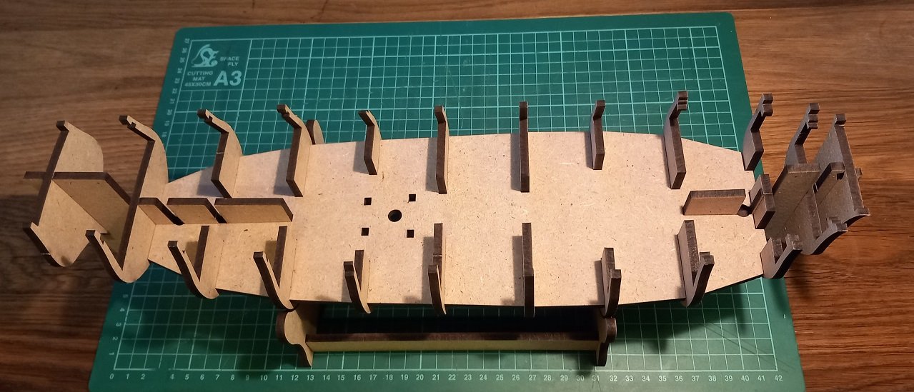
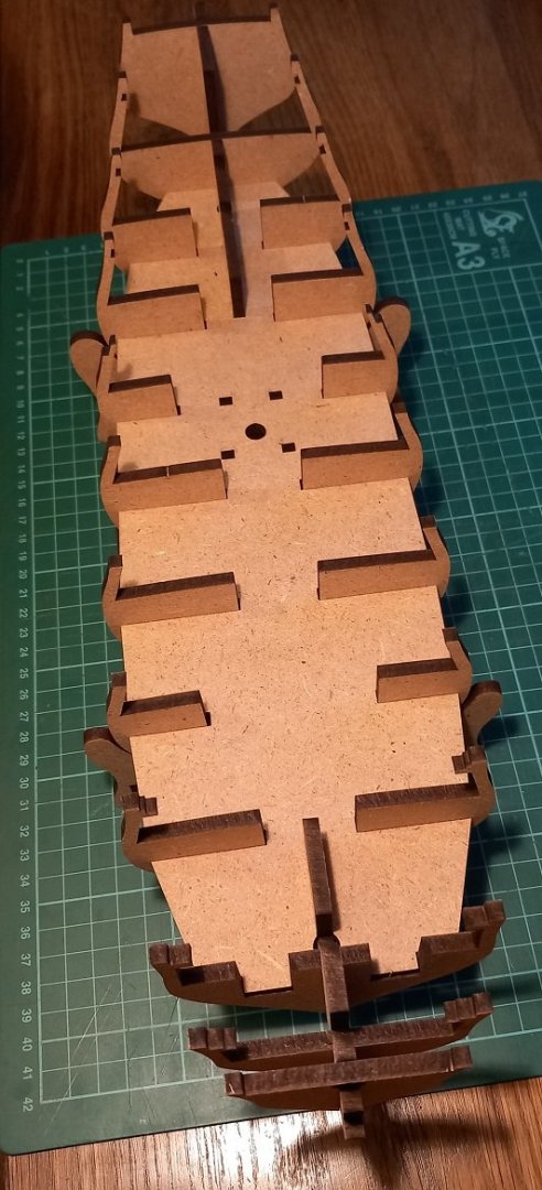
No issues cutting the MDF parts out and assembled it all dry..... note the final frame (part 13) is not fitted yet. Also I have not sanded any of the frames yet just cut them out and fitted them. I'm gunna need a bigger boat...I mean cutting mat! Goes together really well, nice tight fit. Things to do now are:- Mark off the frames on the keel piece (part 14) ready for drawing the bearding line. Mark the lower deck height on the rear of the keel piece for removal of the extra height to make way for the cabin. Disassemble. Cut the keel piece around the rear cabin. Mark and cut the rabbet on the keel piece. Sand the stern to half thickness. Reassemble. I'm not going to 'rough' sand the frames as recommended as I will be blocking the hull up to the MDF lower deck and have found that they are a great visual aid when sanding to the desired shape due to the darker laser cut edges of the frames. I will also resist fitting the walnut keel, sternpost and stem until after the frames and the blocking are complete to avoid any scratching, scraping or sanding of them. A new rear frame (part 13) will be cut from walnut sheet as will the frame preceding it (part 12) to accommodate the cabin area. The final assembly and gluing of the frame structure will also have to wait for a decision on the lighting as routing the wires will be a huge pain in the sternpost! So to my first (of many I'm sure) question... What type of lighting would have been used not only in the cabin but also the lower deck? Would something like this have been used? I think that's enough excitement for tonight. Avast me hearties!!!!!!!!

- 29 replies
-
- 4
-
-
- Fly
- Victory Models
- (and 1 more)
-
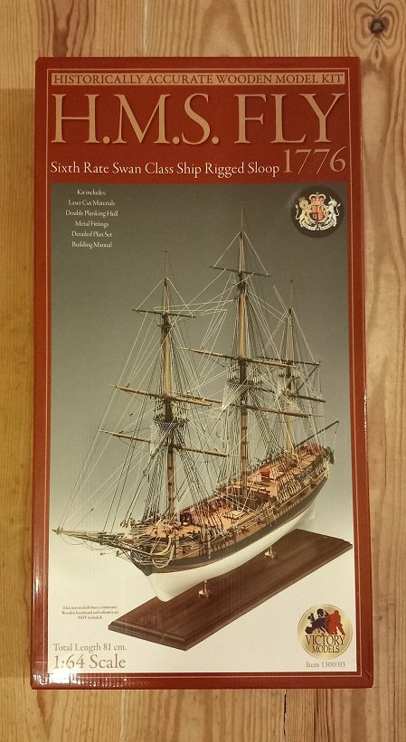
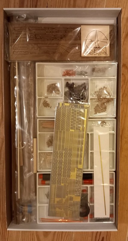
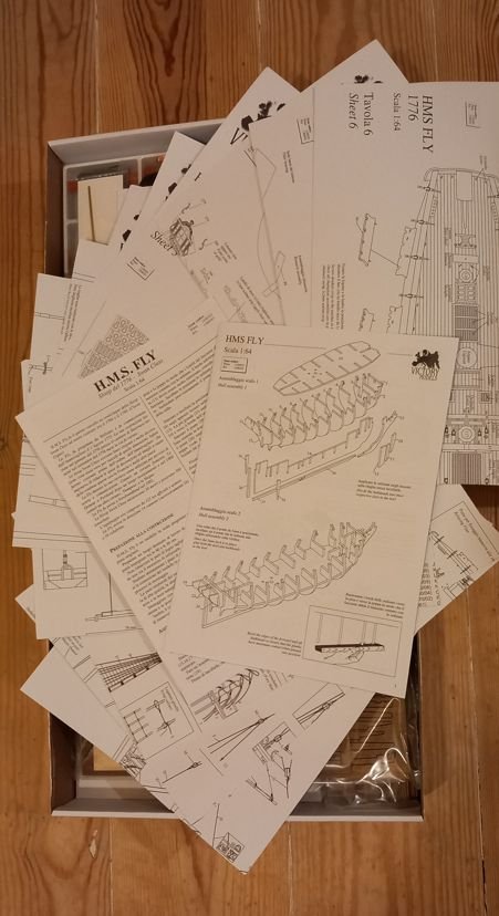
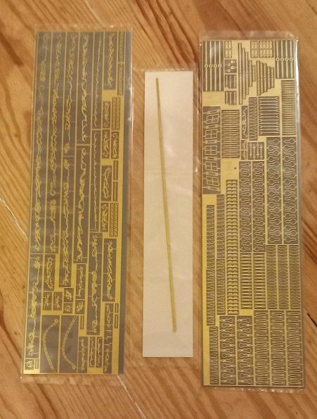
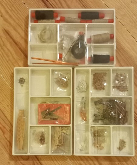
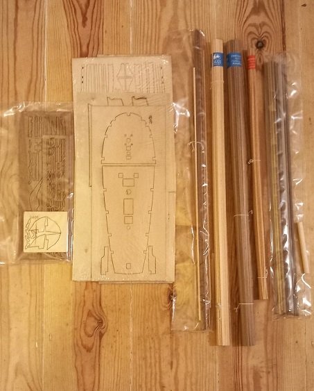
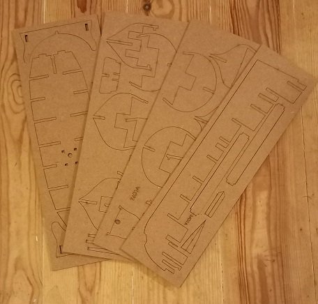
'On the shoulders of giants...' I have to say that the build logs here for HMS Fly/Pegasus have been an inspiration to me on how to navigate my first true 'scale' ship. Particular thanks go to Blue Ensign for posting his Pegasus build... TWICE... after the great crash. I received the kit a few weeks ago but was torn between my 'one at a time' philosophy of boats under construction. That has now changed and I'm going to make a slow start (and probably build) of this excellent kit. In December 2022 I started building HMS Golden star and am using it to resurrect some woodworking skills not used since building Kiel-Kraft balsa spitfires, Fokker triplanes and Stukas back when my age was a single digit (I'm now over halfway to 3 digits!). The Golden Star is progressing but am a little 'hung up' on the fact that its not a true scale model of any particular ship, but as a starter in this hobby it serves its purpose as an excellent training build. There is yet another build on the go of a scratch built HMS Victory but I needed to get retrained hence the current builds. The current plan (and this may and probably will change) is to build it with full cabins at the rear (again thanks Blue Ensign), leave the hull planked (in Boxwood) unpainted and not coppered. Guns and carriages will be changed to Syren, boat kits will be added and the thought of dinner by candlelight in the Captains cabin is very tempting (flickering LED lights). So after breaking etiquette by not showing the 'opening the box' series of photos in my Star build here they are... The box And inside.... Lots of plans which I haven't looked at yet... Brass photoetch....nice.... (cant be as hard to assemble as a 1/24 scale Martin Baker ejection seat in PE can it?) Hours of fun here.... I've got wood.... and finally the 4 MDF sheets. I think I will spend the evening dry fitting the hull and building the cradle, although a 'scale' slipway will be created for display purposes (which I probably wont need for a few years!). Avast me hearties!!!!!!!!
- 29 replies
-
- 8
-
-
- Fly
- Victory Models
- (and 1 more)
-
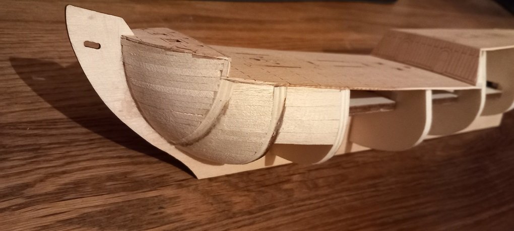
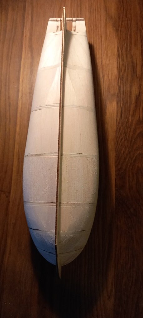
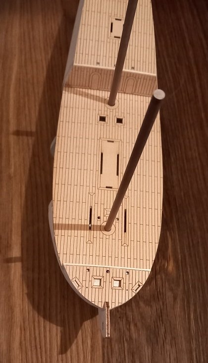
Final blocking... starting with the stern... And some careful sanding later... And the final gap... And I'm calling the blocking done. Next job is to open up the rear hatch a little and then the P word....planking.
-
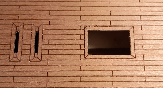
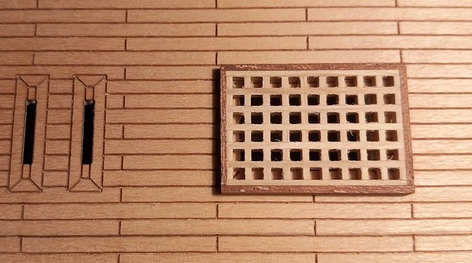
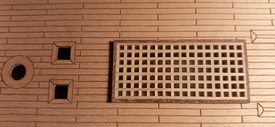
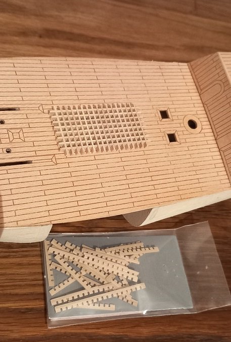
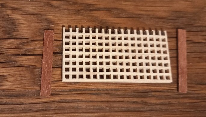
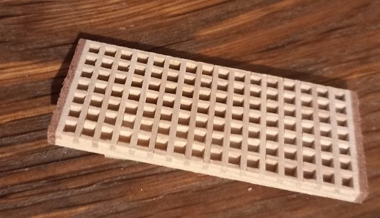
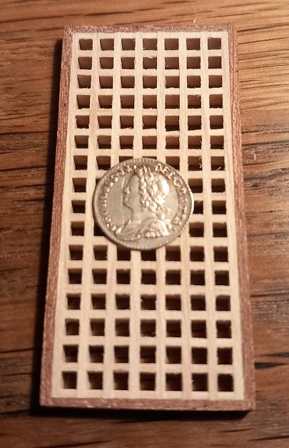
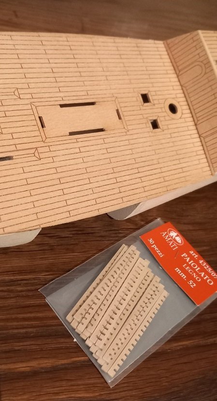
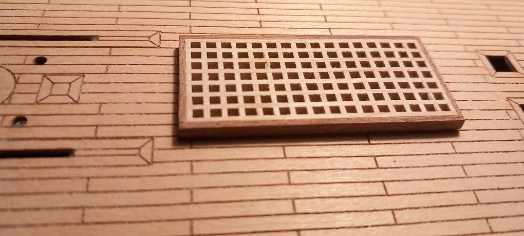
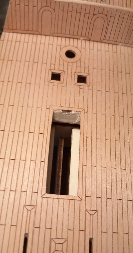
For those of you not familiar with a 1758 silver penny's size this might help with scale. And after some P600 sanding.... you can still see the remnants of the chipped grating and a little more sanding is required to remove it (from top left its 5 holes across and 3 down). The grating was 'painted' with another two coats of 50/50 PVA/water and no further chips were created by sanding its thickness down. Decided to put the remaining grating parts to use, I didn't like the hatch cover on the rear deck so opened it out. And made a smaller grating again with 1mm walnut frame. The hole still needs to be enlarged slightly which will be done once all blocking is complete. Also need to remove the 'fur' on the edges of the grating and have a set of carbide files, one of which is about 1mm square which is perfect for this task. I also glued a 1/16 inch sheet of balsa under the main hatch to catch any shadows although stopped short of adding planking underneath. Finally have decided to fully block out the rear of the ship and this and the blocking between frames 5 and 6 are the last to do....where did I put that 5mm balsa... Not to much progress but I'm still working a full time job which is getting in the way, cant wait to retire and spend my days on my hands and knees looking for that part that the carpet monsters have eaten.
-
Don't know why it insists on adding the last photo twice? Tried deleting the copy of the last photo but cant?!?
-
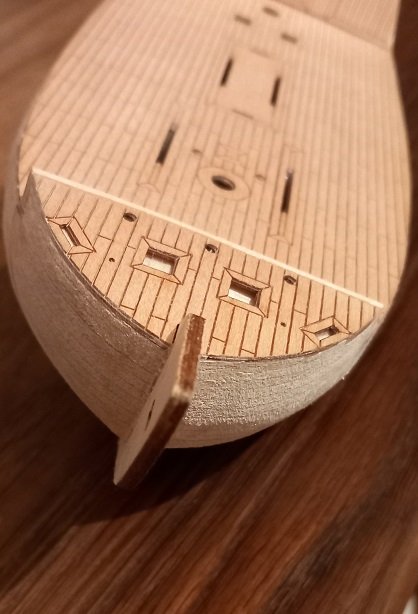
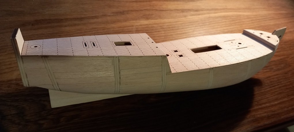
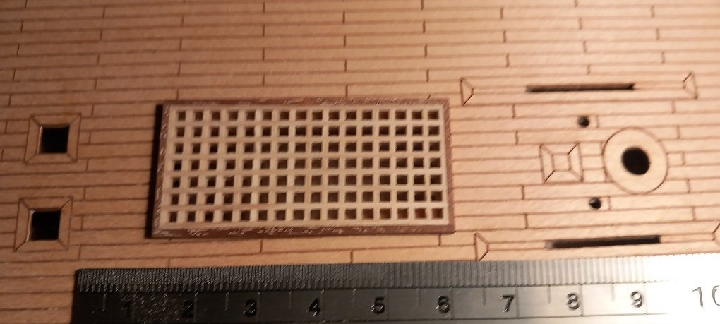
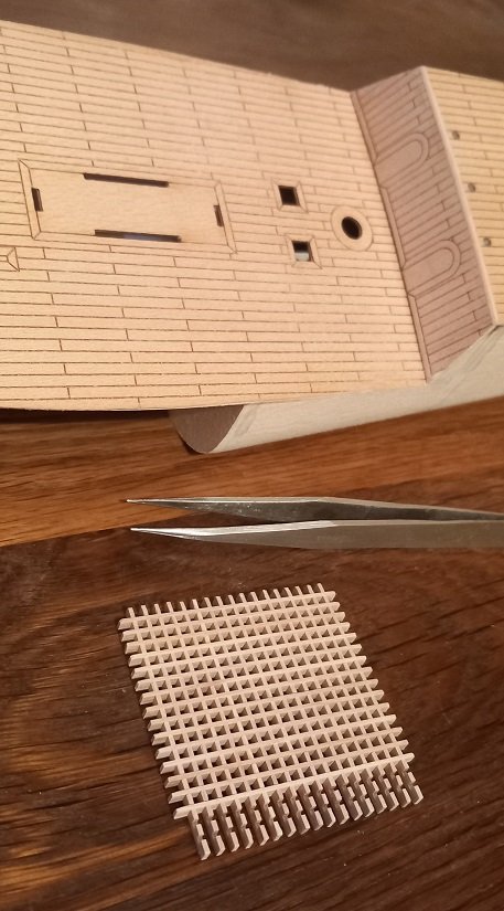
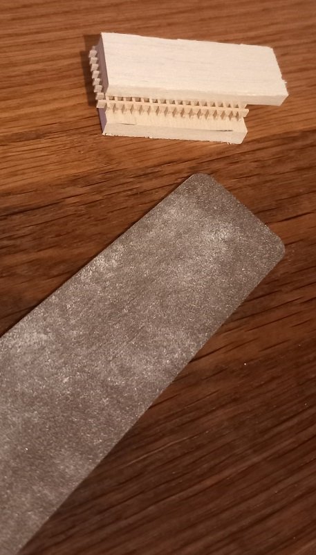
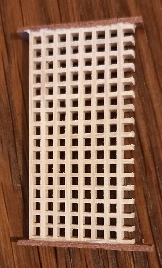
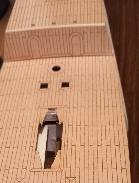
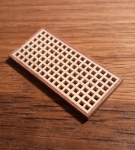
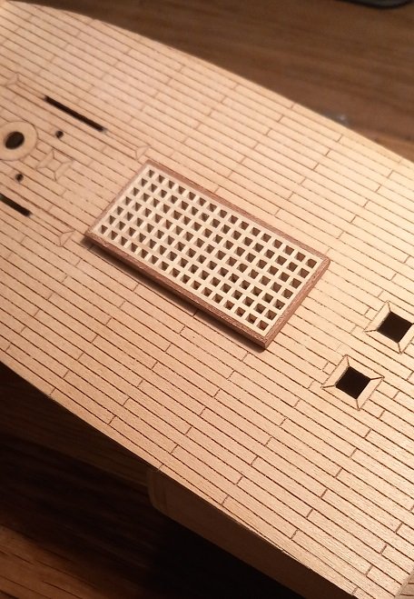
Many thanks Knocklouder. I see you have a Viking ship as a future build, get the Billings 1/25 Oseberg kit it looks great and don't ask me how I know. Now where were we..... oh yes, the hatch. Didn't like the kit version so got a 52 x 52 mm hatch. assembled it... Checked for size required and cut to size. Enough left over for another hatch for another day. 50/50 water/PVA brushed onto the grating and left to dry. Then 'clamped' between two scrap balsa blocks as sanding the edges starts. One more grating edge to go and 1mm walnut sheet cut to rough size for the frame. I glued the ends now as one edge of the grating came loose. Then attacked the hull. The aft part of the opening was over frame 5 and so I filed this back at an angle. Once walnut edges were dry sanded them back. Then added the final frame pieces and sanded. For scale here is a 1758 silver penny. Dry fit. And a final shot of the hatch, no final sanding yet as the grating needs to be about 1/2mm lower to get rid of a few 'chips' in the grating. Before the final sanding I will give it another two coats of 50/50 PVA/Water to avoid any more splits in the grating. I was considering planking below the grating, which is why I have left the blocking between frames 5 and 6 till last but once the hull is finally fully blocked it will be very dark so I will just put a balsa sheet down on the longitudinal frame stiffeners to simulate the lower deck.

-
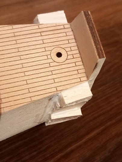
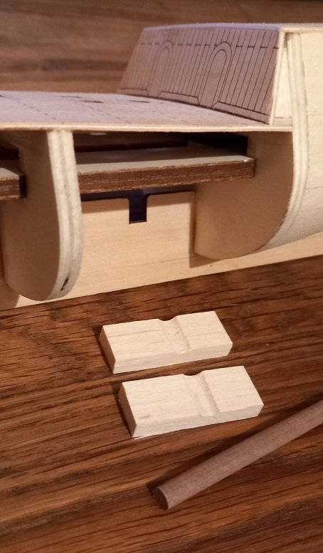
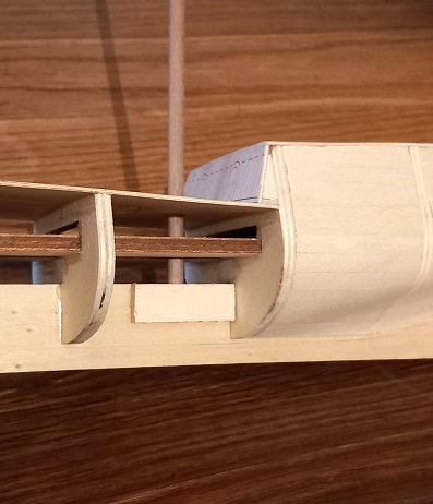
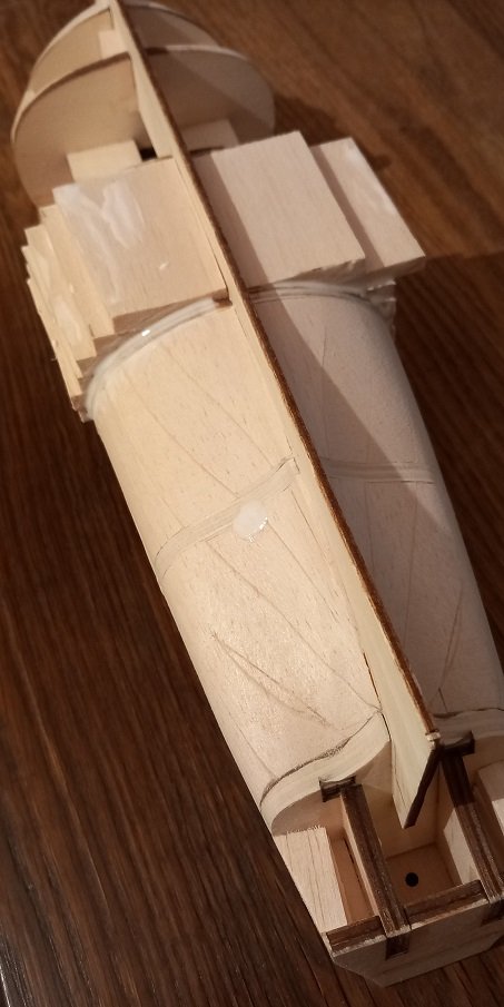
Two balsa block with correct sized groove for the main mast support. Glued in place, care was taken not to use to much glue to avoid gluing the mast in. repeated for the fore mast, its beginning to look like a boat... I can now block between bulkheads 4 and 5... Are we there yet?
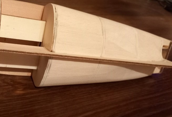
-
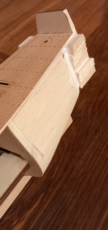
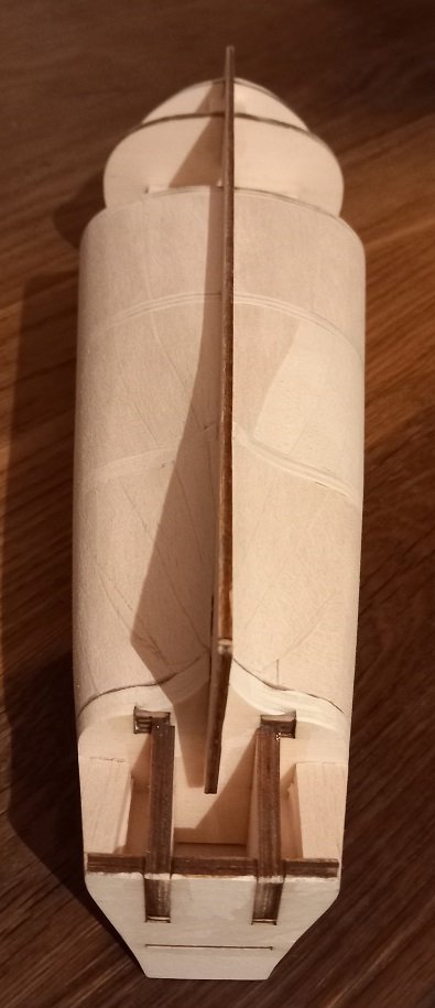
This is my second ship I've started, the first needs more skills than I have at the moment hence the need to start somewhere. The first ship is still waiting for the dockyard foreman to start cutting the keel, deadwood, stern and stem pieces. I also know nothing about the trials of rigging hence the practice ship before a more 'scale' model kit (HMS Fly on its way) and then I will tell the grey foreman to lay the keel of my POF 1/64 scratch build of Victory. 'Golden Star' was in my local hobby shop so decided to hone my skills on this although 1/150 will be fun when rigging. I believe this is a fictitious ship design although still a Brig so will not pay to much attention to the plans and go where the model takes me. I digress..... Blocking continues in preparation for the first layer of planking. The keel pieces will be swapped to cover the laser cut planks on the other sides and a hatch will be created in front of the main mast. As 'modelling for god' seems to be a thing I will plank a false deck below the hatch (as if you could see it through the gratings anyway) before I complete the blocking. I will also glue some balsa over the notches for the masts in the keel and file a notch in each side so the masts sit in the hole created. The dreaded ply edge on the deck... PVA glue fills any small gaps, but who cares it will be under 2 layers of planks! I dry fitted the keel outer pieces prior to gluing and marked the edge in pencil, you can just make it out here. Getting there... When you start to see smooth curves created by the sanding its getting close. And a final shot showing the rabbet pencil line. I'm not creating a rabbet line as the two keel side pieces will do that once attached. Next job is mast supports for the keel.
-
I eventually got some 1/4 inch balsa to speed up the process of blocking between the frames. A few hours later...