HOLIDAY DONATION DRIVE - SUPPORT MSW - DO YOUR PART TO KEEP THIS GREAT FORUM GOING!
×


Doc Watson
-
Posts
39 -
Joined
-
Last visited
Content Type
Profiles
Forums
Gallery
Events
Everything posted by Doc Watson
-
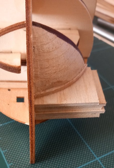
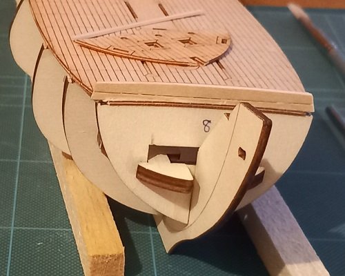
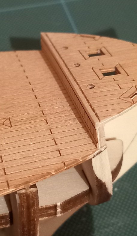
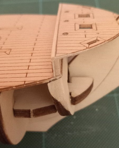
 The bow section has some tight curves and I had some 1/8 balsa so proceeded to block the bow.
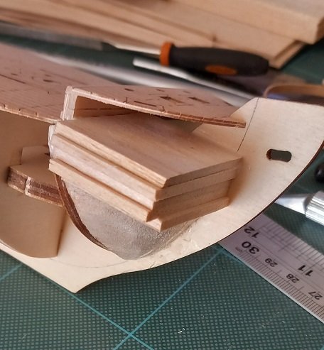
-
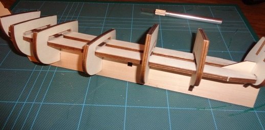
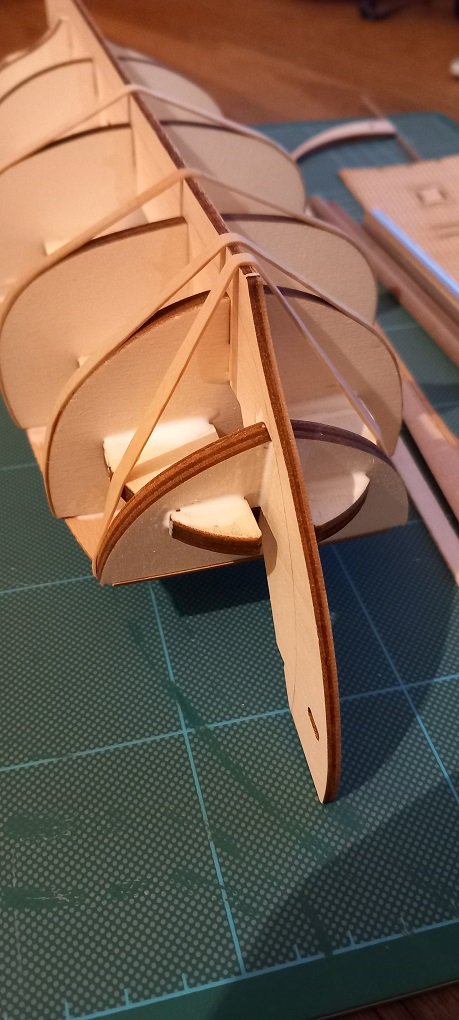
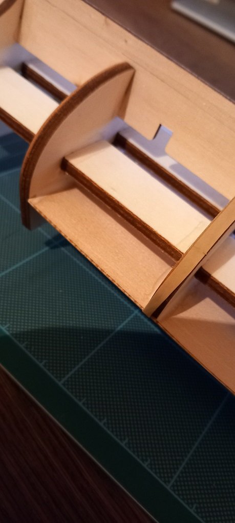
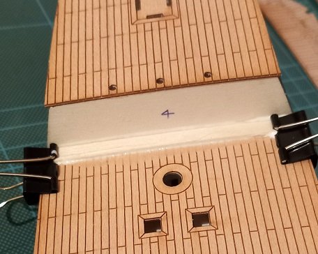
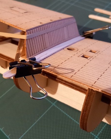
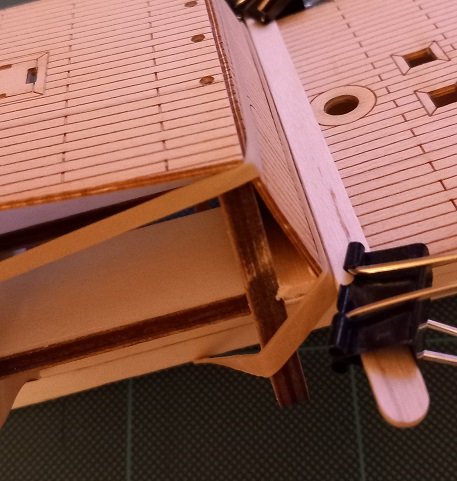
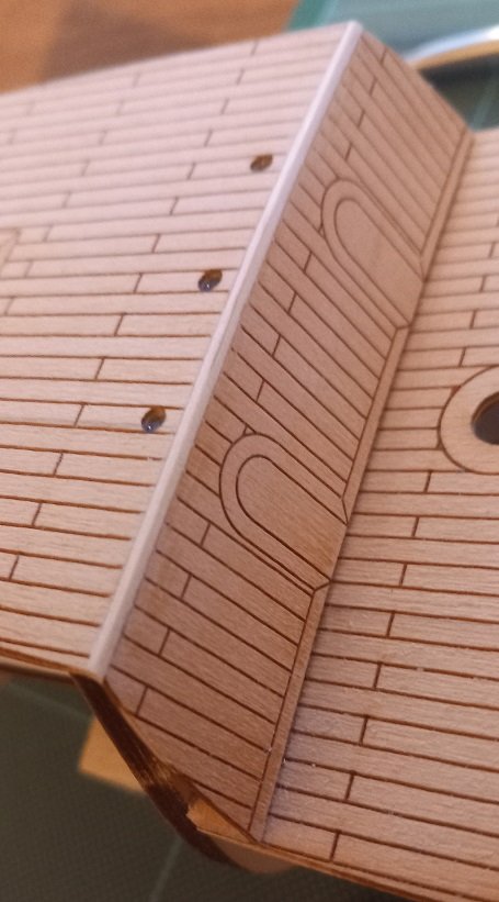
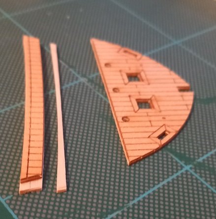
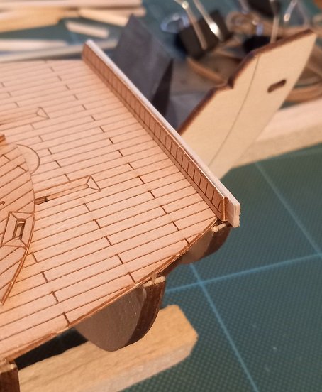
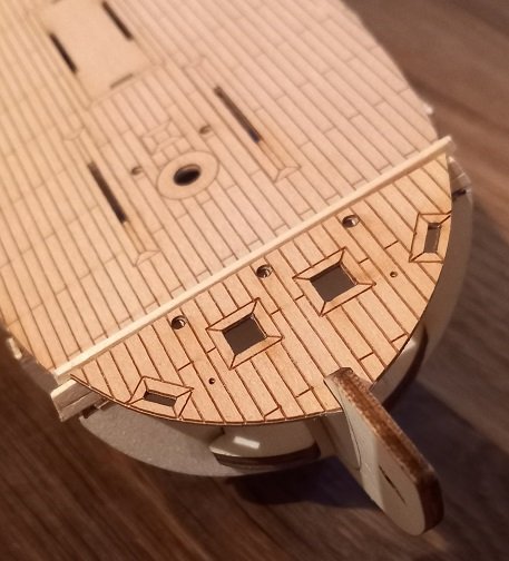
Sorry I didn't do the 'open box' montage.... I did start this kit in December 2022 and have been slowly working on it when time allows. I have been taking photos as I progress and will get this thread up-to-date. First I dry fitted the main bulkheads and keel. Then glued. I felt no need for any keel clamps as the longitudinal plywood bracing kept the keel straight and the bulkheads at 90 degrees to the keel. I also just added a generous bead of glue around all joints without taking the assembly apart. Then attached the decks with the glue still fresh, ensuring there was no warping of the keel or twisting of the deck. After 24 hours drying the structure was solid. I added a small strip to support the angled bulkhead between the upper and lower decks. And added the slanted bulkhead. Hmm, don't like the visible plywood edge... ...so added a small hardwood strip. I also realised that I should have sanded the bulkhead a little more where it meets the lower deck, but I have a plan for that. I think this 'no plywood edges showing' may be my downfall. Moving forward to the foredeck (is it a foredeck?). I added some wood to the back of the curved piece to aid gluing, the backing was from a wooden coffee stirrer, once dry I carefully cut off the excess from the top and bottom and was careful to make one continuous cut for the trimming of the top. Dry fit of the 'step' I then glued the foredeck and used the trimmed piece mentioned earlier as the 'plywood edge' cover. Sanded the filler carefully down to the deck height and decks complete. I sanded the stepped area back as can be seen by the removed charring on the front bulkhead.
-
I live in Plymouth UK probably less than a mile from where Anson was built. Look forward to the build.
-
Superb work, what mill do you have (and it is a rotary indexer Greg). I also love the weird 'helpers' that appear from time to time. Looks like they are now putting out requests... I would go for Echoes..... my fav PF track. Andy
-
Thanks for posting the video! it was interesting to note that as the slipway 'sunk' as a ship was built they just added a new set of timbers onto the old ones, and who wanted the job of sawing in the pit!!! Again thanks for posting this. Andy
-
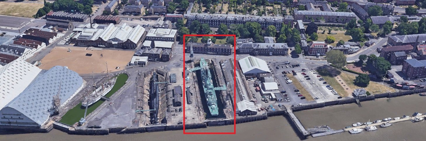
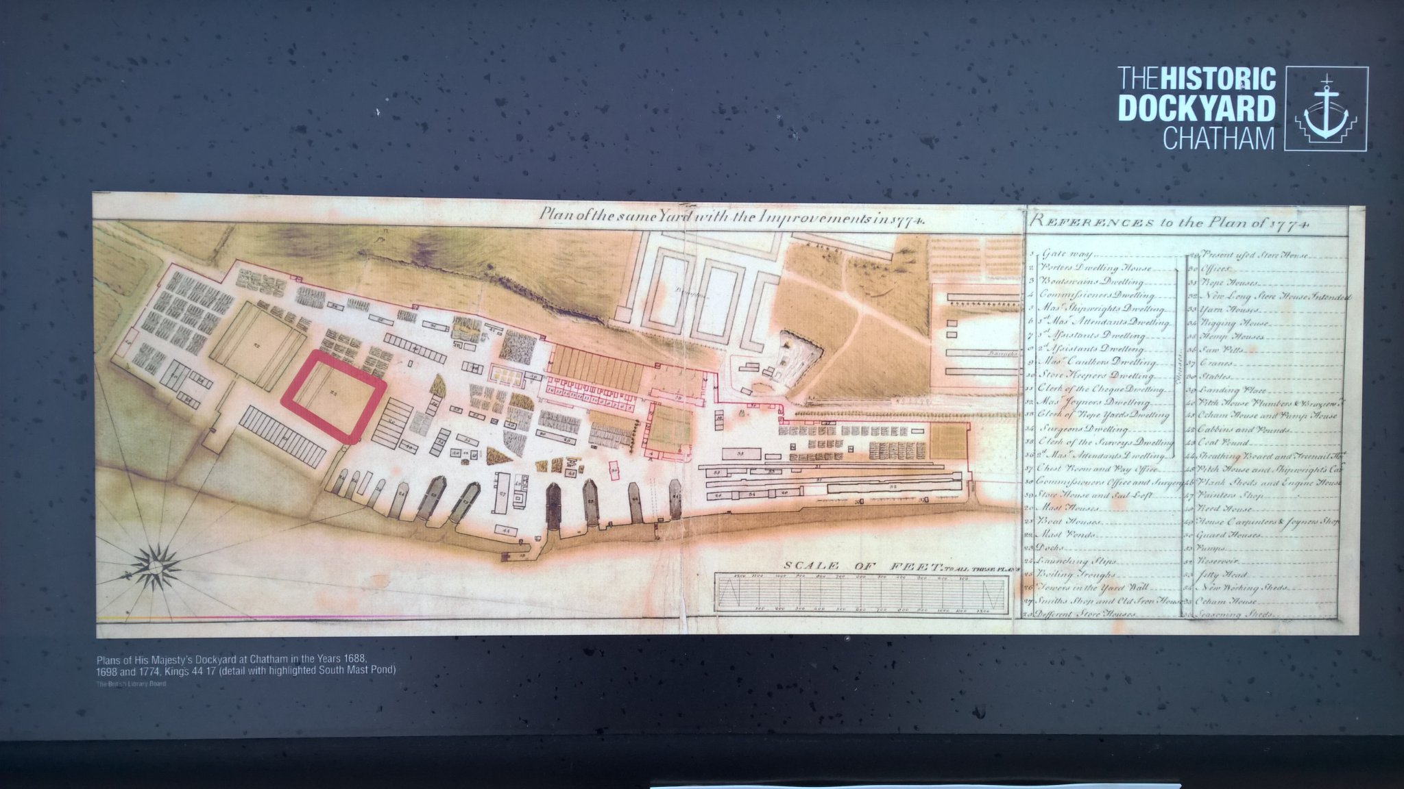
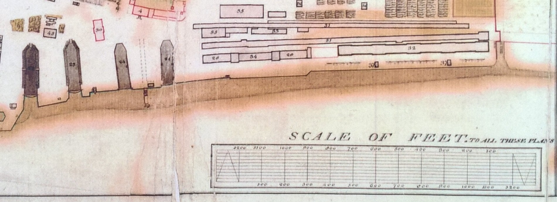
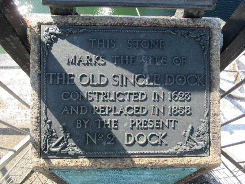
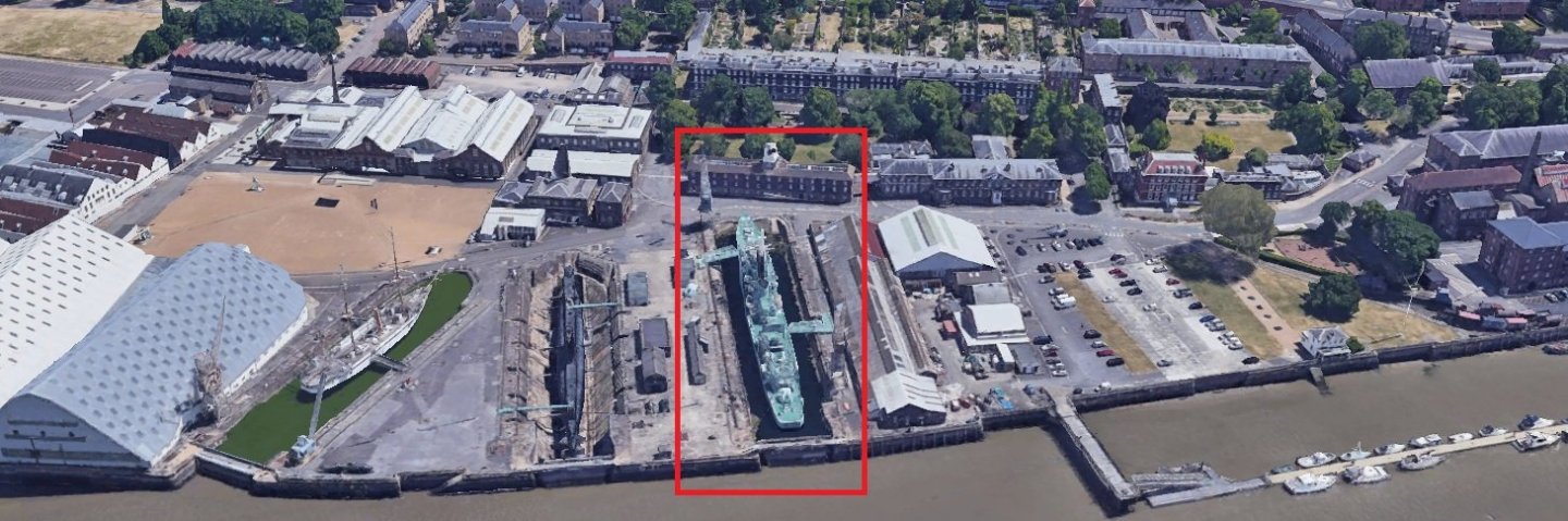
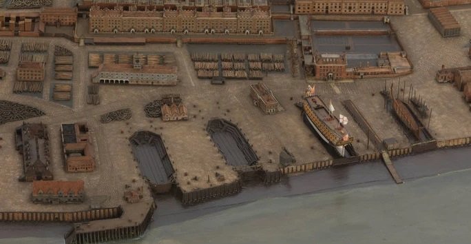
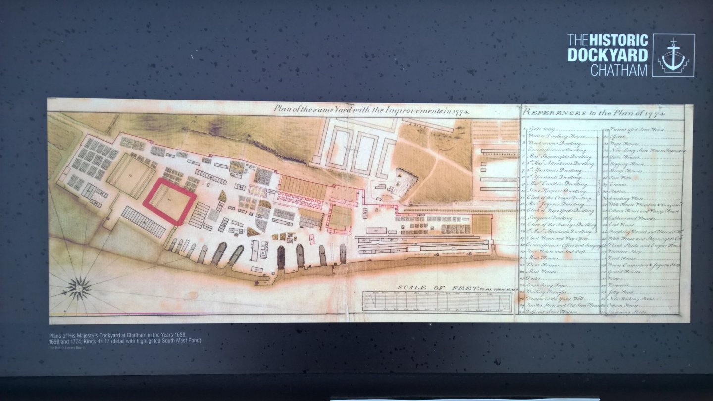
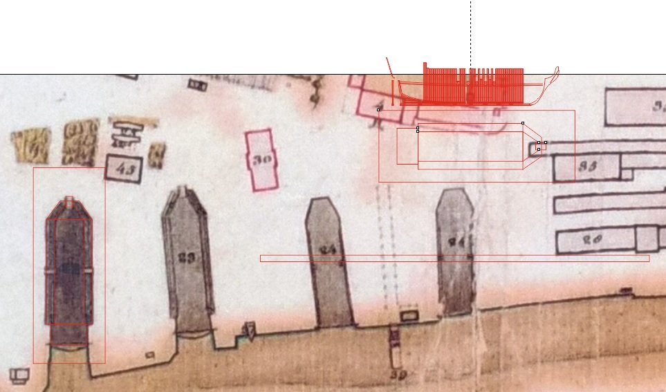
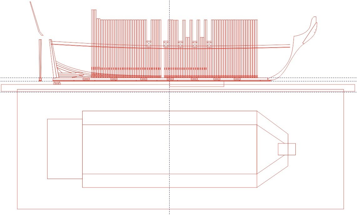
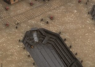
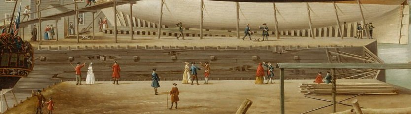
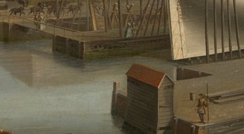
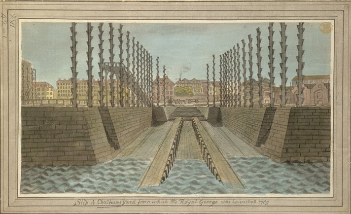
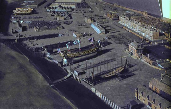
So what did the 'old single dock' look like? well to start I found this plaque by no. 2 dock at Chatham. And presently has HMS Cavalier in the dock, so a quick look on google earth gave me this.... Outlined on red is No 2 Dock with HMS Cavalier in situ. Note that the dock lines up with the left of the clock tower building. Now we come to the model of Chatham from 1772-1774 only a few years after the Launch of HMS Victory. Notice the clocktower building and which dock lines up with it. Another angle of this model with 'the old single dock' being on the left. Now there is also a map of Chatham from 1774 and you can identify the drydock in question. It also contains a scale and using this I cropped the image and scaled it to my drawing of HMS Victory and using my drawing package of choice (Coreldraw) copied the outline of the dock and then compared it with my current drawing of Victory. The cropped image is shown and interestingly shows the ropery on the left which is still there. The 'old single dock' is the leftmost on this image And here is the outline of the dock to the correct scale... copied, rotated and put next to the ship. And an image of the dock against the ship, its a tight fit! So the basic size is set now for the question of construction, first how many steps on the inner walls.... This close up of the dock shows 3 steps and also some detail of the stairs at the front of the dock for the shipwrights. The dock was made from Elm as it resisted rot, also notice the 4 capstans (red lead colour) and the position of possible bollards along the edges of the dock. I say possible as they could be short posts in lieu of the longer poles (the name escapes me) which were used as scaffold as the ship was being built. So I have ordered the wood for the base and for reference the rectangle around the dock in the last drawing is 1200mm x 440mm. So we now come to construction of the walls and the best reference for this was found from contemporary oil paintings principally from John Cleveley the Elder who was a retired shipwright turned artist. The next two images show detail of the wood around various docks. Also the first image gives some detail of the dock gate and how it was supported internally from the pressure of water at anything but low tide. Finally, I found a picture of a dig of a slipway from Depford and it shows the base of the slipway with with the beams of wood striding the sides of the dock. The above paintings include 'damaged' to areas of the dock walls but gives a look at the vertical wood piles I assume which were driven into the ground behind the horizontal walls. Another interesting point are the hollow square brick 'bases' around the slipway which as they are regularly spaced along the sides of the slip (or drydock!?) would have been used to put the scaffolding poles or moorings. I have also found that the maximum tide range at Depford is about 6m and the depth of the drydocks was around 25 feet which is 7.6m. With the above information I can finalise the drydock dimensions and make a start on constructing it. Then I can lay the blocks that the keel will sit on and start the build proper. I have a drawing of a slipway from 1789 showing the 'scaffolding poles' does anybody know the real name for these? which from previous evidence could be slotted into the square bases seen in the Depford dig or possibly replaced with shorter 'mooring' posts. From the look of this drawing the poles had wedged steps added up the length of the poles (possible at set heights) to allow ramps to be easily attached to help construction. I dont think they were carved from a solid log as this would have wasted most of the log. Any opinions??? I had some additional information from Brian which tells the story of how the gate sides had to be removed as the ship was calculated to be 9 inches wider than the thinnest part of the drydock (the area around the gate). This included a copy of the original report by the dockyard worker in charge of floating out Victory. Sorry for the rambling but I wanted to show the background behind what I think the 'old single dock' looked like and how I came to get the final dimensions of the dock from contemporary sources, draw the basic dimensions and hopefully make a start on the dock soon. Andy


-
Many thanks for the information Greg, two books ordered and on their way to me.
-
Doc Watson Plymouth England..... Ahoy!
Doc Watson replied to Doc Watson's topic in New member Introductions
Thanks for the warm welcome, build log has been posted.... hope I got the title right!! just ordered wood for the frames and base and hope to start cutting wood to shape soon... -
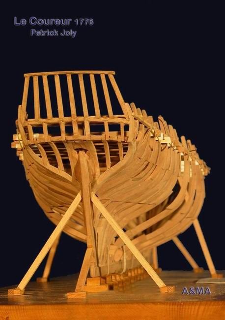
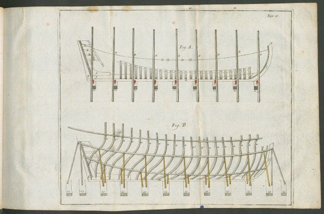
Yes I will be building her as she was launched, I'm going to also have her built up as she was in the dock so it will be a kind of moving diorama as with my speed of building I will be staring at it more than working on it. I will initially put the keel on blocks and found similar models shown, also attached is the 'Sutherland' diagram for building and supporting a ship as its constructed. A link to the book is here... https://echo.mpiwg-berlin.mpg.de/ECHOdocuView?url=/permanent/library/AE4UUGBR/pageimg&start=51&pn=56&mode=imagepath If you can get passed the fact that an 's' was printed as a 'f' its an interesting read...

-
A few pictures of the 'old oak' and some workmen on the job... the final picture is the only reference I have for Chatham dockyard around the time of Victory's build. If memory serves its a model of the dockyard in Greenwich Maritime Museum.

-
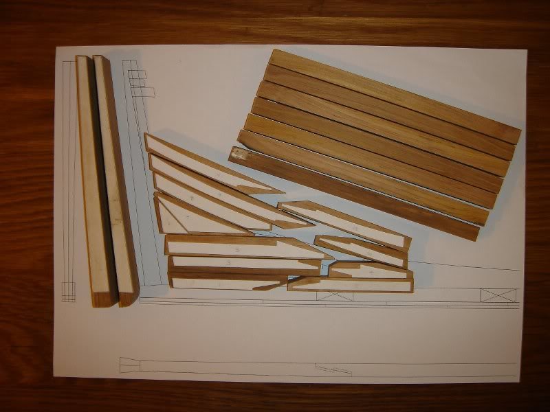
'Even a journey of 1000 miles starts with the first step' About 16 years ago I started drawing up plans for a 1/64 scale POF Victory and after a few years on other projects have resurrected the plans (from an old computer) and decided to create a build log of my glacial progress. I have John McKay's 'Anatomy of the Ship' for reference and have scanned and scaled the images and drawn some of the ship in 'Corel Draw' and have started work on the keel and stem and stern. After looking at the official web site for Victory I saw that they will sell 'old wood' taken off the ship when repairing and renovating various parts. If you want some of the wood you have to 'request ' it by stating how much you want and what it will be used for. So after writing to the Naval officer in charge and explaining I wanted to build this model he agreed and a few blocks of wood arrived (not cheap!) and included certificates of authenticity signed by the acting Naval officer. I have enough for the keel, stem and stern and most of the dead wood. The keel wood came in a block which need to be ripped into approximately 10mm x 10mm lengths and after using a saw (no progress on 200 year old oak) then trying a hacksaw (still little or no progress) I asked a colleague who teaches woodworking at a local college where I now work to cut it using a bandsaw. He came back a day later with the wood cut down but then asked what wood it was as the bandsaw usually lasted a month before sharpening the blade and only just managed to cut the pieces before being re-sharpened, good job I didn't tell him before he cut it! I was then worried about how I could cut the scarph joints in the keel so bought a small milling machine which will hopefully do the job!!! I still have a relatively large pieces of oak left which seems to have the ochre paint and some 'red lead' paint on it and might have come from one of the gun ports. I will post some pictures of the pieces I have later this week. I also want to build the model sitting in 'The Old Dry Dock' so the build will hopefully be a diorama of the ship as the keel and frames are built up. One or two questions if I may... 1) Has anybody got any information on what the Chatham 'Old Dry Dock' looked like in 1765? 2) I have been sourcing wood for the frames and have found some Swiss Pear of the correct thickness (a few thou under 7/32") is this a good choice for the frames? Andy
-
After a hiatus of a few years and a frantic search of an old computer I have found my plans for a 1/64 POF Victory and am 'back in the saddle' so to speak and will start construction in the new year. I have some original oak from HMS Victory which will be used for the keel and stem, stern and some deadwood, not cheap but wanted a piece of the original in the build. I will start a build log in due course and am in the process of acquiring wood for the frames. A time served mechanical fitter then design engineer, Navigator in the RAF and since 2000 a lecturer in computing. Started getting wood dust in my lungs at an early age building balsa rubber powered models and about 25 years ago built a 'Billings' Bounty which has now gone to the great shipyard in the sky. I have a few other projects on the go including a Gauge 1 live steam 'Evening Star' and a 1:1 scale GT40 with monocoque made to original drawings and many original parts which did require a remortgage of the flat and I've been on that project for only 15 years so far so dont expect quick progress on the ship!!!