.jpg.6c90d67e7e9071af590f4d4a2a8bc908.jpg)
Waldemar
-
Posts
1,003 -
Joined
7 Followers


-
 Rik Buter reacted to a post in a topic:
Dutch heavy frigate ca. 1700 – engineering or carpentry ‘snowman’ making?
Rik Buter reacted to a post in a topic:
Dutch heavy frigate ca. 1700 – engineering or carpentry ‘snowman’ making?
-
Rik Buter reacted to a post in a topic:
2nd rate London 1656 – the art of the shipwright
-
Rik Buter reacted to a post in a topic:
2nd rate London 1656 – the art of the shipwright
-
Rik Buter reacted to a post in a topic:
Samuel 1650 – a Dutch mid-17th century trader
-
Rik Buter reacted to a post in a topic:
The Dutch 72-gun ship ca. 1690 – the apogee of Dutch ship design of the Classical Age
-
druxey reacted to a post in a topic:
Nate's PANDORA in 3D
-
Waldemar reacted to a post in a topic:
Bateau de Lanvéoc by JacquesCousteau - Scale 1:32 - From Ancre Plans
-
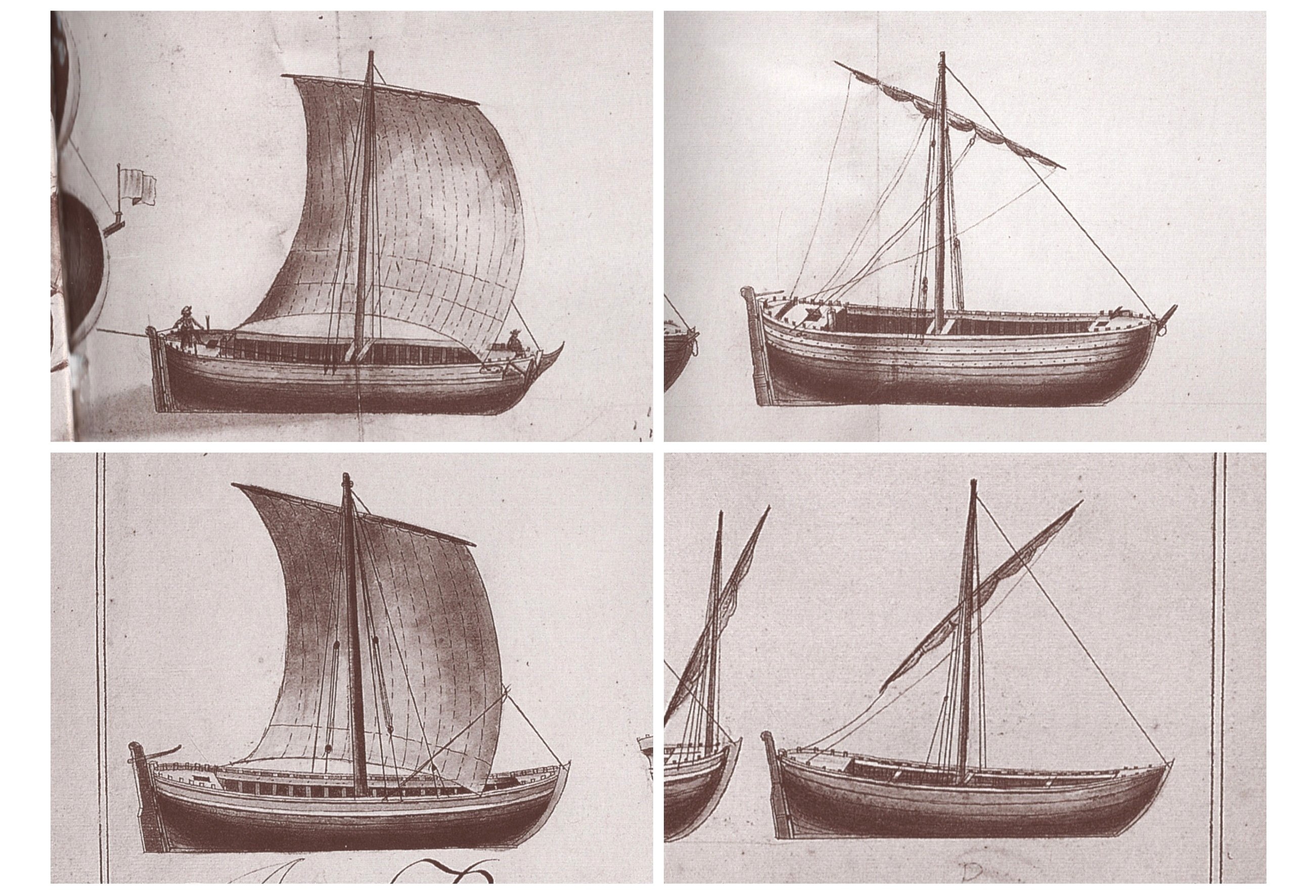
.thumb.jpg.c6343966b029e7941df5b987d129aac6.jpg) Just to “maliciously” make your choices even more difficult , I’m including further images of boats of this type, from the so-called Album du Ponant of 1679. By the way, many thanks for your report and photos from Madrid.
Just to “maliciously” make your choices even more difficult , I’m including further images of boats of this type, from the so-called Album du Ponant of 1679. By the way, many thanks for your report and photos from Madrid.
- 139 replies
-
- 6
-
-

-
- ancre
- Bateau de Lanveoc
- (and 2 more)
-
Waldemar reacted to a post in a topic:
Hvide Ørne and Wildmanden by Arthur Goulart
-
Waldemar reacted to a post in a topic:
Bateau de Lanvéoc by JacquesCousteau - Scale 1:32 - From Ancre Plans
-
And yet this is exactly how it was made in Sweden in 1684.
-
However, this is assumed by all artillery related early treatises and manuals I know of, up to the age of Industrial Revolution, and I see no reason to apply 19th-century standards to 17th-century realities. I think you should also familiarise yourself with the numerous geometric methods of determining these diameters, given in textbooks from this early period, and always regardless of calibre. Also, allowances for powder proportions and length in absolute measurements are never given. Lieste, this is just different world, and reciting specific values from a 19th-century textbook is definitely out of context.
-
Lieste, that's all well and good, but these are late 18-century and later, 19th-century standards. What exactly do you propose for the reconstruction of this particular early 17th-century calibre scale?
-
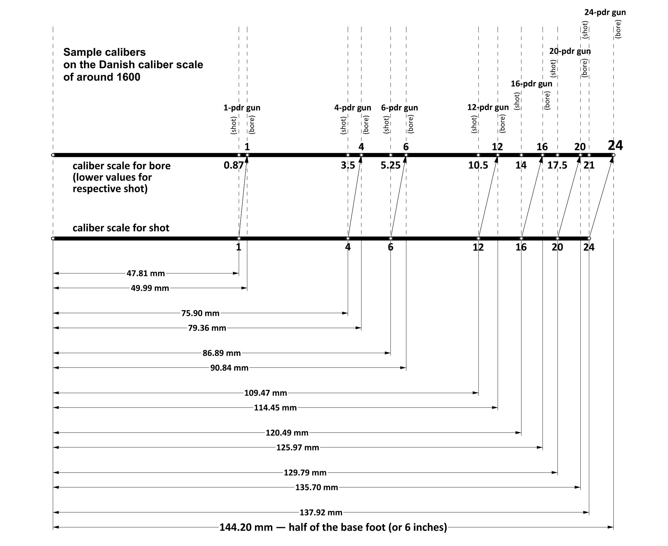
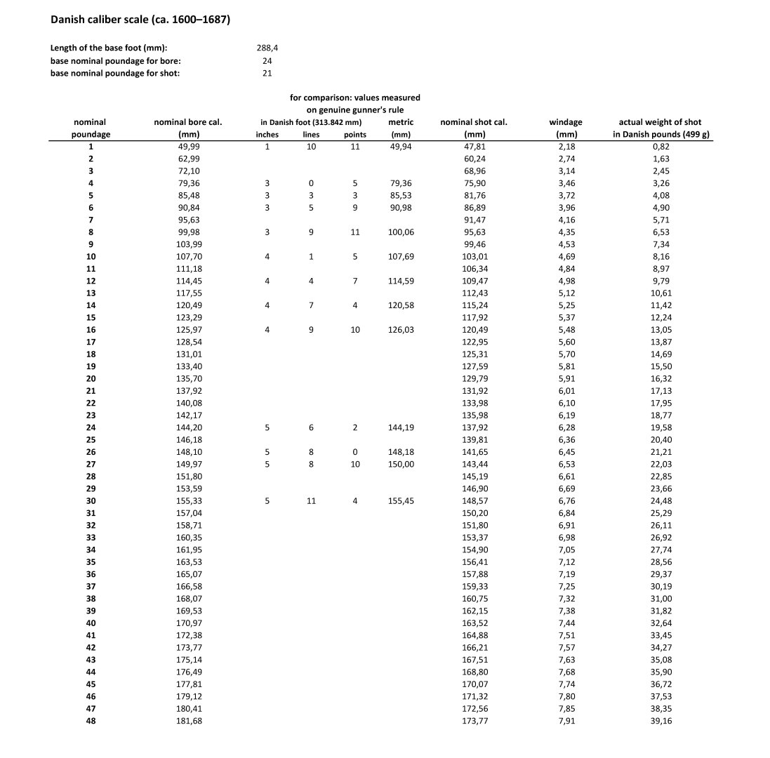
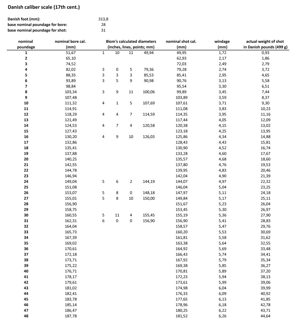
Now, after reading the relevant passage from Blom's work, it is at least known what he did, what he didn't do, and why. Although I generally consider Blom's work to be reliable, apt, and cognitively valuable (as far as I can judge based on other passages), it is, unfortunately, weaker when it comes to determining calibers and the way of their defining by the contemporaries. First of all, on this particular issue, he essentially rejected the analysis and general conclusions of the Danish general and historian Fibiger that the basis for calculating calibers in Danish artillery of that period was the method invented and defined by Hartmann (see above for the definition of this method). Instead, he engaged in rather esoteric comparisons of the total weights of projectiles taken from contemporary documents, which could not even provide any precise results. In addition, it turned out that Blom, in a partially arbitrary and, consequently, quite unrealistic way, matched the poundage of shot to the poundage of bore for specific sizes of cannons known from inventories (tables on p. 103 and 192 in Blom's work). This is why, according to Blom, the windage for an 8-pounder cannon is absurdly significantly greater than for a 30- or 26-pounder cannon , which is in obvious contradiction to the commonly known mathematical and geometric methods of determining the mutual relationship between bore and shot diameters, which are (almost) always uniformly proportional (for example, the rule: shot diameter = 20/21 bore diameter, regardless of caliber). Fortunately, Blom quoted specific values read from a contemporary gunner's rule (caliber scale), which I also included in the below table for comparison (here, there is perfect coverage across the entire caliber range with the reconstructed caliber table). In addition, Blom also cited a reading of the length of one inch (according to the Danish measure) from the same gunner's rule. The length of this one inch is not entirely consistent with the caliber scale from the same gunner's rule, but the difference from the length of one inch in the reconstructed base foot length is very small (0.13 mm) and can be considered within the measurement tolerance or workmanship tolerance of the gunner's rule itself. I came to the conclusion that the values read from the contemporary gunner's rule refer to the diameters of the bore of cannon barrels, which are intended for firing cast iron shot of this poundage (for the construction of the previous table, I made the opposite assumption, i.e., that they refer to the diameters of the shot). It can therefore be said that in Denmark it happened in exactly the same way as in Sweden (or vice versa), i.e. around 1600 (in Sweden in 1616) the 24-pound caliber was assigned to the diameter of the bore, while in 1687 (in Sweden in 1684), the same 24-pound poundage was assigned to the diameter of the shot. The reconstructed length of the base foot for calculating the caliber scale is 288.4 mm, which is one millimeter more than the length of the Cologne foot (287.396 mm, according to a value given in a mid-19th century work, or more precisely from 1838). I have adopted a number of 21 as the base poundage for calculating the diameters of the shot. This number yields realistic windage values and, at the same time, is also consistent, as far as possible, with the data given by Blom in his work. The difference (i.e., three pounds for the base poundage of 24) is the same value known to be adopted in Swedish artillery in the 1684 reform. If someone prefers a smaller windage, they should change the base value of 21 to a larger number, for example 21.5 or 22, and vice versa. As it stands now, here are a few examples for typical calibres: A 48-pounder cannon fires shot of nominal poundage of 42 A 36-pounder cannon fires shot of nominal poundage of 31.5 A 30-pounder cannon fires shot of nominal poundage of 26.25 A 26-pounder cannon fires shot of nominal poundage of 22.75 A 24-pounder cannon fires shot of nominal poundage of 21 A 20-pounder cannon fires shot of nominal poundage of 17.5 A 16-pounder cannon fires shot of nominal poundage of 14 A 12-pounder cannon fires shot of nominal poundage of 10.5 An 8-pounder cannon fires shot of nominal poundage of 7 A 6-pounder cannon fires shot of nominal poundage of 5.25 A 4-pounder cannon fires shot of nominal poundage of 3.5 It is also graphically shown in the diagram below. Just in case, so as not to leave this reconstruction anonymous, I sign it with my name: Waldemar Gurgul.

-
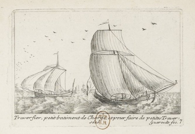
Here is another image of a „traversier”, or rather two images in one. From around 1700. Hopefully you will find something useful in it.
- 139 replies
-
- 6
-
-
-

-
- ancre
- Bateau de Lanveoc
- (and 2 more)
-
Waldemar reacted to a post in a topic:
Danish cannons for 3D printing
-
Yes, absolutely. Until quite recently, such effective 3D modeling was not possible. If you do decide to make these 3D models from the era of Christian IV available, I will also download them. It is possible that I will also find a use for these models. Thank you. However, this may not be the final version of the caliber scale, because other combinations are indeed possible, for example, using the Rhenish (Cologne) foot instead of the Danish foot. Nevertheless, the very essence of this method of calculating calibers must be correct, and finding the base values for this construction can be indeed useful in practice. Anyway, I am continuing my work on this scale, and now I am translating the entire passage from Blom's work (pages 100-110), because there he quotes specific readings from sources of the era, in particular specific values from actual gunner's rules.
-
Waldemar reacted to a post in a topic:
Danish cannons for 3D printing
-
 Waldemar reacted to a post in a topic:
Muscongus Bay Lobster Smack by Kenchington - Model Shipways - 1:24
Waldemar reacted to a post in a topic:
Muscongus Bay Lobster Smack by Kenchington - Model Shipways - 1:24
-
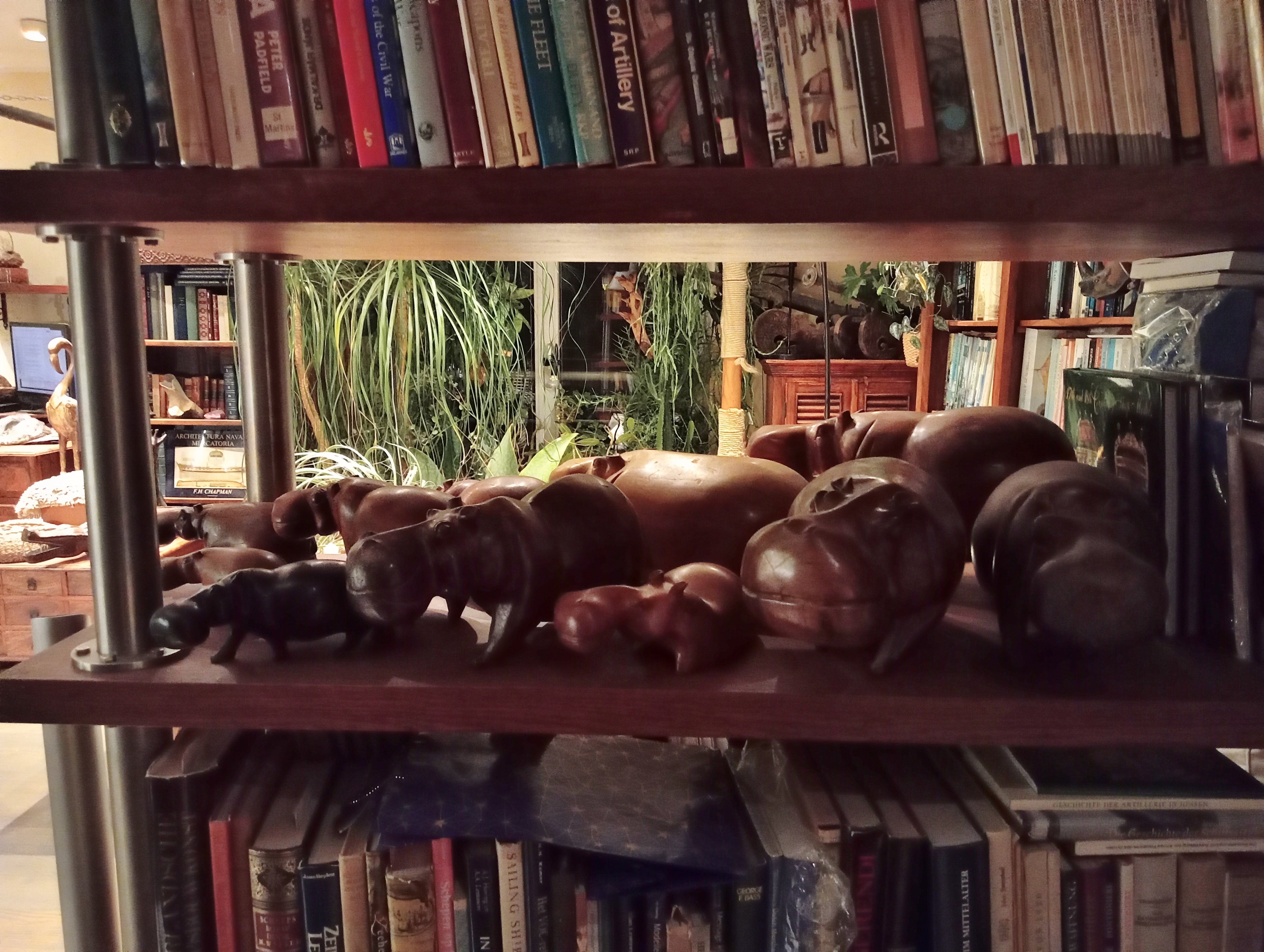
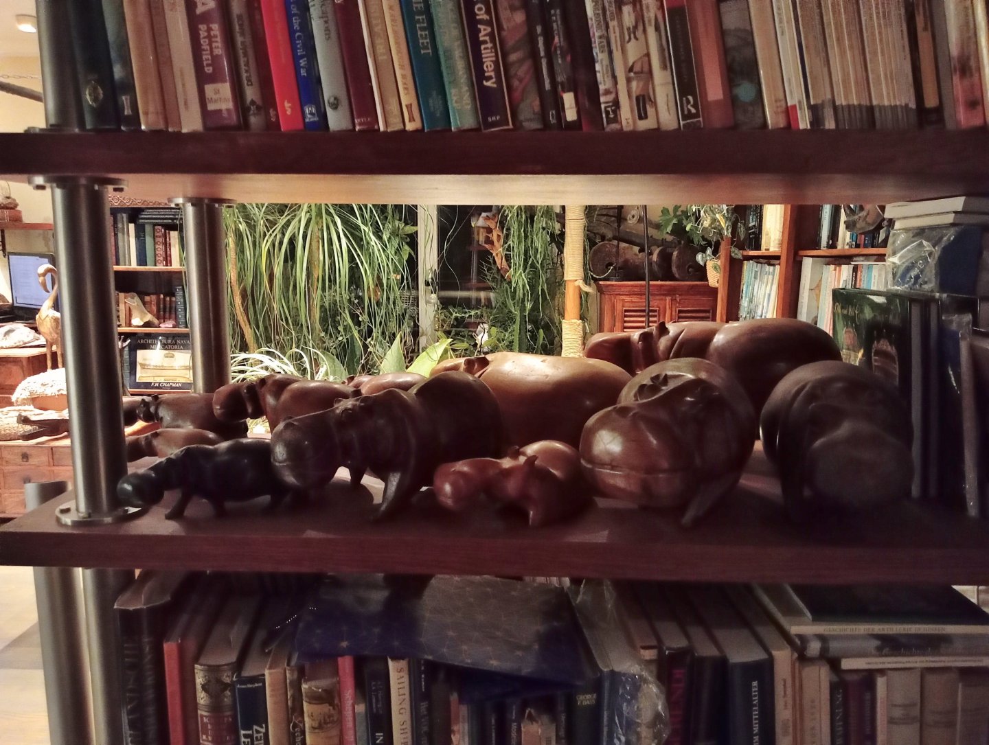
I was just looking through your presentation and, strangely, came across part of my collection at your place . But seriously, I have to protect my hippos collection like the apple of my eye, because every now and then someone wants one of them as a gift. I explain that it's a sort of collection and that's what gives it its added value, but I can see that this doesn't stop them from being disappointed by being refused...
-
Waldemar reacted to a post in a topic:
Muscongus Bay Lobster Smack by Kenchington - Model Shipways - 1:24
-
Waldemar reacted to a post in a topic:
Danish cannons for 3D printing
-
Returning to Blom's table of calibres, reproduced above, I believe that he assigned too small a shot size to small and medium-sized guns. Why would the windage for an 8-pounder cannon (according to Blom, approx. 9 mm) be almost twice as large as for a 30-pounder cannon (5.36 mm)? It should be the other way around...
-
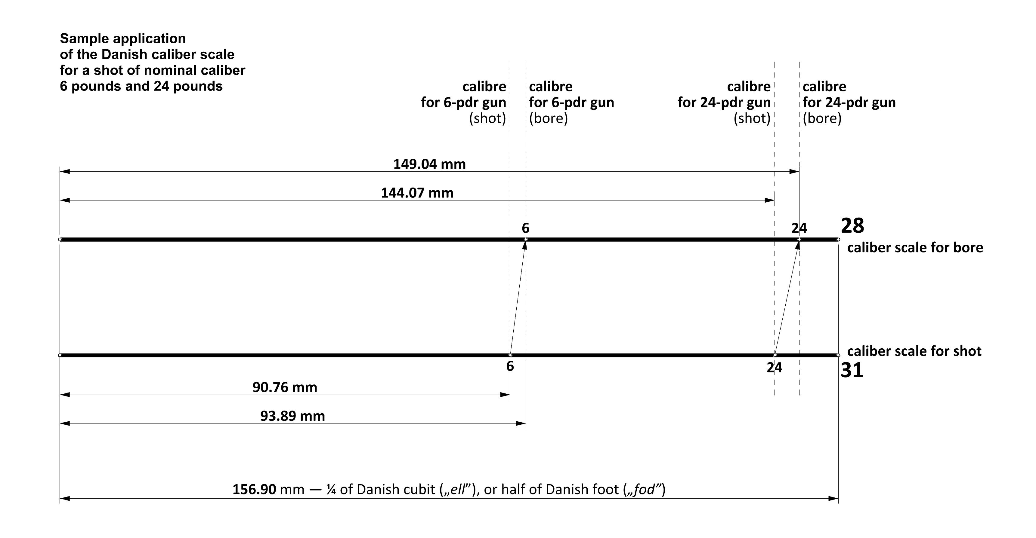
To demonstrate how Hartmann's Nuremberg caliber scale (in the Danish variant) actually works, here is a graphic showing the determination of bore diameters for two sample shot calibers — 6-pound and 24-pound. Both scales are pre-calibrated according to the equation given above. In fact, using the poundage was only necessary to obtain the final result in absolute units of length for diameters (since the shot was spherical in shape), which was facilitated by Hartmann's double caliber scale (separately for shot and bore). To find the bore diameter for a 6-pound shot, one would only need to take it from the the upper scale (for the bore) for the respective poundage, i.e. 6-pounds. And vice versa, to find the shot diameter for a given bore caliber, the reverse procedure was followed.

-
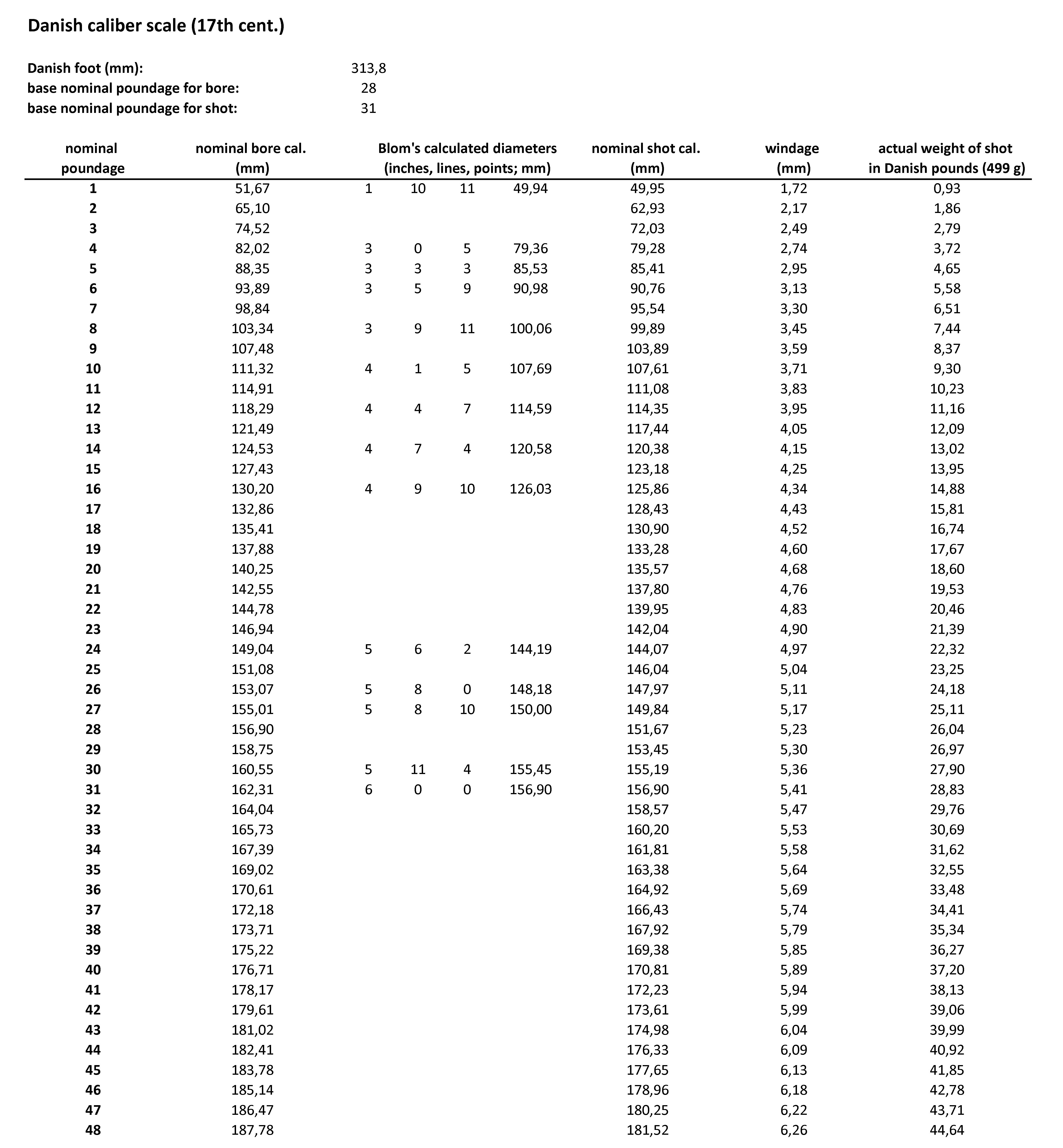
I think I got it, that is, the essence of the Danish calibre scale in the era of Christian IV. Its construction is actually quite simple, but it may require a rather difficult mental shift. The Danish 1/4 ell, or its equivalent – half-foot (I assumed 313.8 mm / 2 = 156.9 mm) was apparently assigned a base nominal poundage of bore of 28 and a base nominal poundage of shot of 31 (in Swedish artillery, after the 1684 reform, 21 and 24 respectively, for the Swedish foot of 296.7 mm). And that's it. Everything else is calculated according to the formula I gave earlier: (diameter-A)3 : (diameter-B)3 = Poundage-A : Poundage-B In a spreadsheet, it is very easy to automatically perform these calculations for all calibres, including fractional ones and those expressed in ounces or lots (after converting them to decimal notation). How to read the attached table? For example: sample 1. A gun with a nominal calibre of 26 pounds shoots projectiles of a nominal calibre of 23.5 pounds (one need to compare the dimensions in mm), or sample 2. A gun with a nominal calibre of 30 pounds – shoots projectiles of a nominal calibre of 27 pounds, sample 3. A gun with a nominal calibre of 46 pounds – shoots projectiles of a nominal calibre of 41.5 pounds. Or, from the other side, i.e. starting with the calibre of the shot: sample 1. Round shot of a nominal calibre of 24 pounds – requires a nominal bore calibre of 26.5 pounds, and has an actual weight of 22.32 Danish pounds, sample 2. Round shot of a nominal calibre of 27 pounds – requires a nominal bore calibre of 30 pounds, and has an actual weight of 25.11 Danish pounds, sample 3. Round shot of a nominal calibre of 42 pounds – requires a nominal bore calibre of 46.5 pounds, and has an actual weight of 39.06 Danish pounds. For comparison with Swedish calibres, a similar table with calculated diameters for Swedish artillery guns is needed. Taking as an example a Swedish 24-pound calibre gun (after the 1684 reform): shot 148.35 mm and bore 155.10 mm, which corresponds to a Danish 26-pound cannon (bore), Or for a Swedish 42-pound cannon: shot 178.77 mm and bore 186.91 mm, which corresponds to a Danish cannon of a nominal calibre of 47 pounds and a nominal calibre of 41.5 pounds (or 42 pounds rounded up). In these comparisons, a slight inconsistency arises from the fact that the Danish system had less windage than the Swedish system, in a ratio of 31/28 : 24/21. As can be seen, there is indeed quite nice equivalence between the nominal calibres in Danish and Swedish artillery, however, quite ironically, in both systems, the nominal calibres were in fact calculated on the basis of somewhat different initial values (i.e. different foot lengths and other base poundages). Cool, isn't it?
-
Waldemar reacted to a post in a topic:
Danish cannons for 3D printing
-
These illustrative materials were automatically suggested by digaltmuseum algorithms when I was downloading, image by image, Thelott's second set (to supplement my first set of this album, which lacks a scale in centimetres). And I was myself surprised and delighted by this completely accidental find. This find is also a direct result of our conversation, because you asked earlier where you could download Thelott's album, and then I found it ad hoc in digitaltmuseum to point you to a source. However, there is a certain difficulty, namely that all these graphics are made available in a rather chaotic, i.e. single manner, yet, fortunately, these individual reproductions are well described in the metadata. The point is that these inventories were not only compiled on different dates, but are also sorted according to specific fortresses (locations). As a result, when downloading, one has to use various tricks, especially specific search keywords to filter out these different sections in the inventories, and this is a task that takes at least two days. In this situation, I can of course give you a few sample links to these individual reproductions (a total of about 270 graphics for fortresses in the east and west of Sweden at that time) and you can search for and download them all yourself. But I think it would be better if I sent them all to you already sorted and segregated via WeTransfer (about 1.5 GB) if you give me your email address in a private message.
-
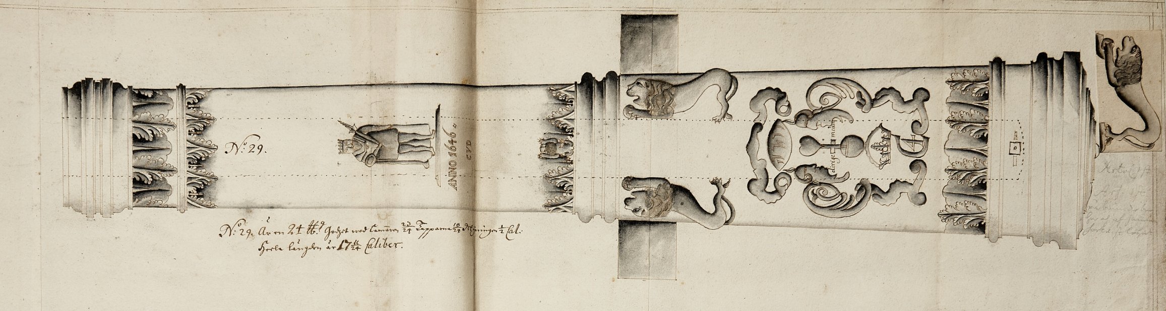
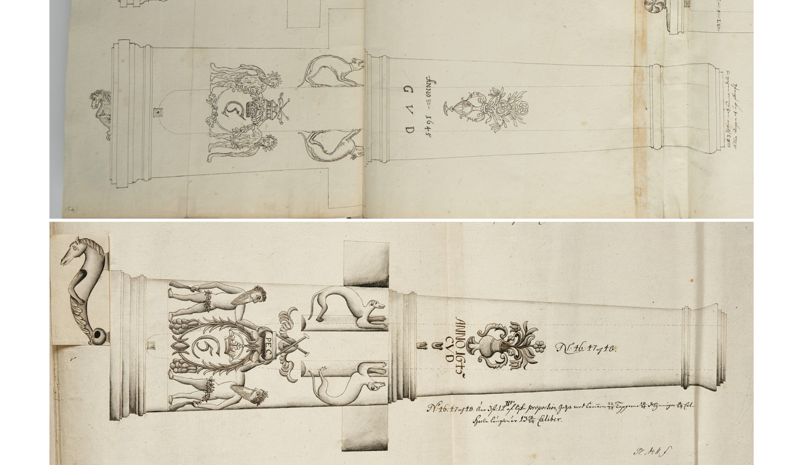
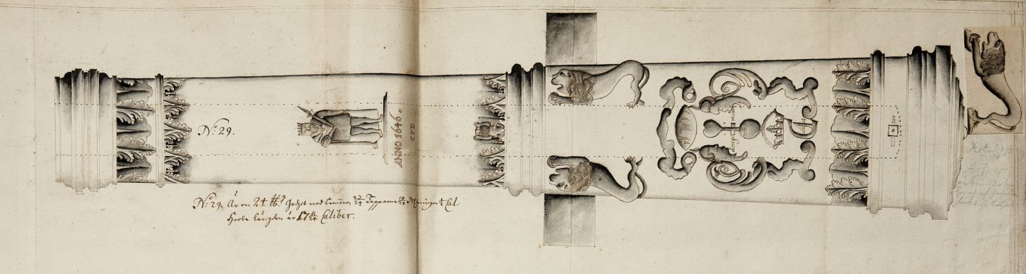
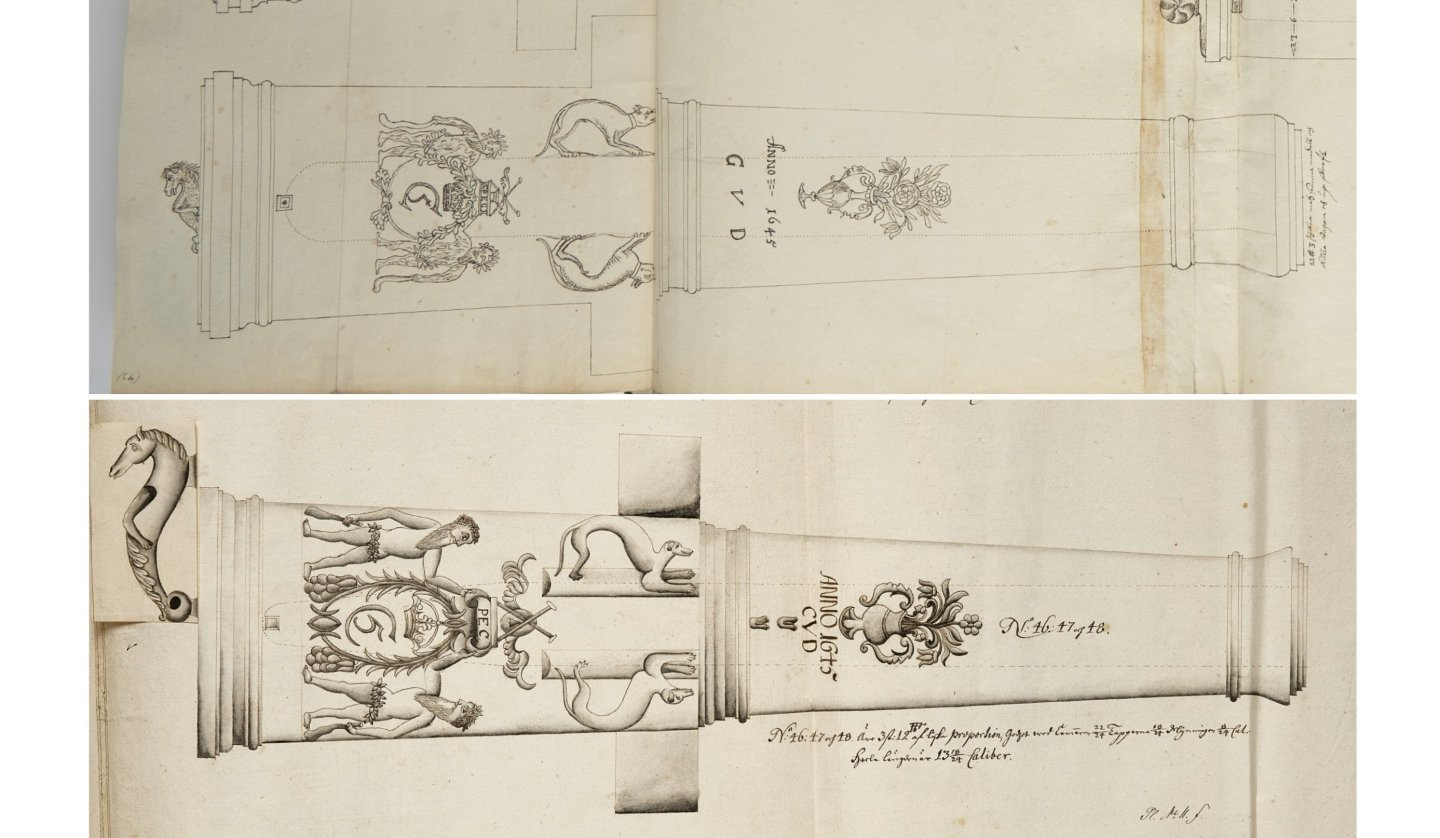
I have compared both Swedish artillery inventories from 1670-71 and 1690-91, i.e., before and after the caliber reform of 1684. Firstly, I managed to find some pairs of the same cannons (of Danish origin), which allowed me to conclude that the 1684 reform was simply ignored by those who compiled the second inventory, because the “duplicates” I found are listed with the same caliber in pounds. Alternatively, the reform had in fact been carried out earlier and was only formally approved in 1684 (or something to that effect). Here is one such example of a pair depicting a Danish cannon (actually three identical guns of the same series), marked as 12-pounders in both inventories (upper one from 1670-71 inventory, the bottom one from 1690-91 inventory): Incidentally, in the Swedish 1690-91 inventory, I have also found a second cannon from the “Nye Konger” series, which in turn is not included in the first inventory from 1670-71, and both are marked as 24-pounders (or maybe it's the same cannon of the two?): I am very keen to reconstruct the original Danish caliber scale used in the era of Christian IV, and according to Hartmann's Nuremberg method. I believe that it was defined analogously to the Swedish caliber scale of that era, which used the Swedish foot measure, i.e., in the case of Denmark, it would be the local, Danish foot measure. Of course, in such a way that everything fits together logically, including data from Swedish sources. Blom's calculations regarding diameters in the above table are somehow not convincing to me, because his starting point for the calculations is apparently the current weight of various, local pounds (Nuremberg and Danish) and the specific weight of cast iron . And yet the beauty and practicality of Hartmann's scale lies precisely in the fact that it deliberately rejects these variable, uncertain components of the calculations. In other words, Hartmann's Nuremberg scale assigns fixed (local) units of length to arbitrarily chosen numbers that determine the nominal poundage of the bore and shot. I am working on it.
-
Thank you very much, Thorbjørn, for your comment. Not only because of the information itself (and also for pointing out a better copy of Blom's work than the one I had; and the other two Danish works I bought personally as hard copies while in Copenhagen quite a long time ago), but also because I was afraid of boring you, or even irritating, which is definitely not what I want . Quite at the same time, I began to wonder what a 42-pound cannon really meant in Swedish artillery in 1691, i.e. when the inventory with this particular barrel was made, and I remembered details about calibers in Swedish artillery of that early period (many years ago, I studied this particular subject quite intensively). My information on this very issue comes mainly from two modern works on Swedish artillery, both extremely comprehensive and detailed, and which I still have in my library: Theodor Jakobsson, Lantmilitär beväpning och beklädnad under äldre Vasatiden och Gustav II Adolfs tid, 1938 Theodor Jakobsson, Artilleriet under Karl XII:s-tiden, 1943 There are, admittedly, also post-war works by Hedberg, Claëson, and Ulfhielm, yet, in technical terms, they do not really contribute anything new and simply rewrite the technical issues from Jakobsson's publications. But to the point: The caliber scale invented by Georg Hartmann of Nuremberg in 1540 is ingenious in its simplicity of application, and its main advantage is also that it makes the calculations of round shot and gun bore diameters independent of the specific weight of iron, stone, and lead, which was, after all, variable. Hartmann's definition is very simple: ¼ cubit (i.e., half a foot or 6 inches) determines a caliber of 24 pounds for cast iron shot (and 37 pounds for lead shot and 7 pounds for stone shot). Other calibers are simply calculated according to the formula: (diameter_A)3 / (diameter_B)3 = Poundage_A / Poundage_B In 1616, Sweden adopted the Hartmann (Nuremberg) scale literally according to its definition, but in such a way that half a Swedish foot (296.7 mm / 2 = 148.35 mm) determined the diameter of the bore of a 24-pound cannon (as opposed to the diameter of a round shot). Indeed, the cannons of the Vasa cast in 1628 perfectly correspond to this measurement within a margin of perhaps 1 millimeter. However, in 1683, a reform was carried out, whereby from then on, half a Swedish foot no longer determined the diameter of the cannon bore, but the diameter of the round shot. In this way, the diameter of the bore of the base 24-pound cannon increased from 148.35 mm to 155.10 mm (standard NATO calibre, by the way ). From then on, as a result of this reform (using a cast iron density of 7.1 g/cm3, which is the value commonly accepted for calculations of this kind in various countries, and the Swedish skålpund, used in Swedish artillery to determine the weight of projectiles = 425 g), the Swedish base 24-pound cannon fired shot with an actual weight of approximately 28.75 Swedish pounds (skålpund). Now, let us return to the 42-pound cannon of Danish origin in the Swedish artillery inventory from 1691. From the above (after calculations), it follows that the cannon marked as 42-pounder must have had a bore diameter of 186.91 mm, for a shot diameter of 178.77 mm. So, in Swedish artillery, it actually fired 50-pound round shots (for 1 skålpund = 425 g). Converted to Danish units (1 pound = 499 g), this gives an actual round shot weight of approximately 42.6 Copenhagen pounds. As a result, taking into account the necessary windage, the nominal bore diameter of this cannon should correspond to a value of approximately 48 pounds. This is how it looks from the “Swedish side” of this puzzle. As a result, I must admit that it is indded a 42/48-pound cannon (shot/bore), and I somewhat regret not having thought about the Swedish side of the “equation” earlier. I hope this is not too complicated and too extensive, but I preferred to provide a complete explanation .
-
@TJM, I have a polite request for you. Let's assume that this Danish cannon, which according to the Swedish inventory is 42 pounds, would originally have been a 48-pound cannon in Denmark. Please rescale this cannon barrel in your 3D program to a 48-pound caliber and recalculate its weight, assuming a bronze density of 8.6 g/cm3 or similar. The result will be for comparison with the weight engraved on the barrel, which is 16 skeppund : 11 lispund, and which according to Danish measurement is 5296 pounds or 2648 kg. This attempt, if successful, should finally remove my doubts on this matter and finally point to the correct solution to this problem.