.jpg.6c90d67e7e9071af590f4d4a2a8bc908.jpg)
Waldemar
-
Posts
701 -
Joined
Content Type
Profiles
Forums
Gallery
Events
Everything posted by Waldemar
-
.thumb.jpg.c6343966b029e7941df5b987d129aac6.jpg) Thank you very much Gregory. Unfortunately this plate is already copyrighted by my contractor (museum) and I cannot dispose of it too freely. There will be another one, in a commercial set, as I have retained the copyright to the design itself, but this will not happen very soon. The best, Waldemar
Thank you very much Gregory. Unfortunately this plate is already copyrighted by my contractor (museum) and I cannot dispose of it too freely. There will be another one, in a commercial set, as I have retained the copyright to the design itself, but this will not happen very soon. The best, Waldemar -
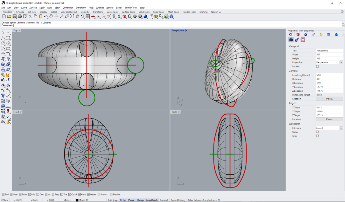
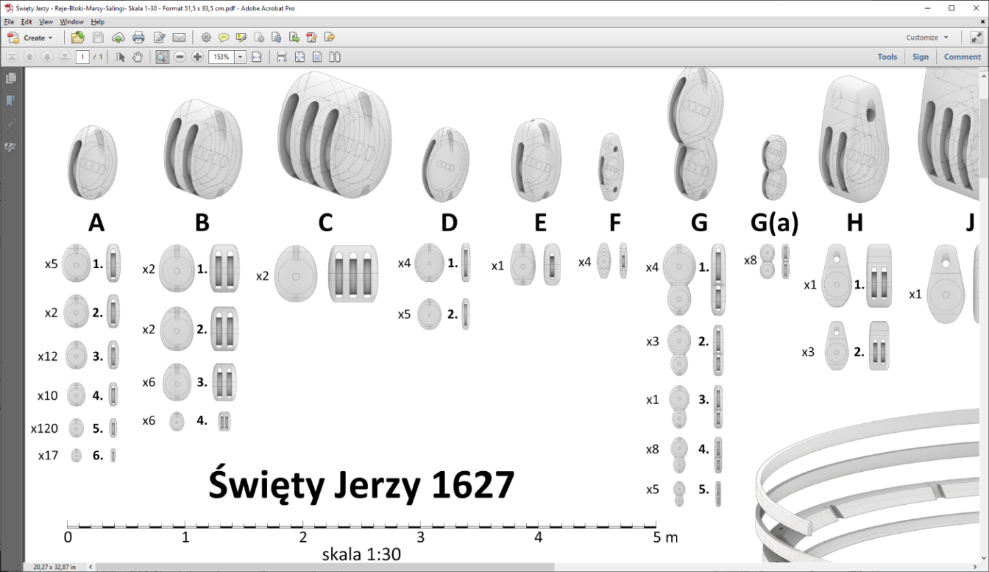
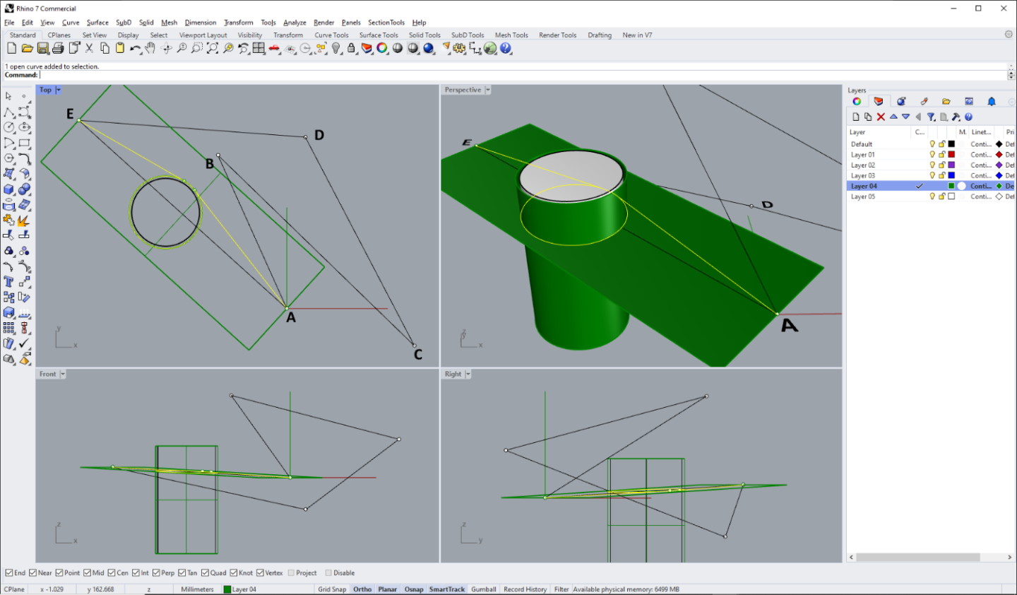
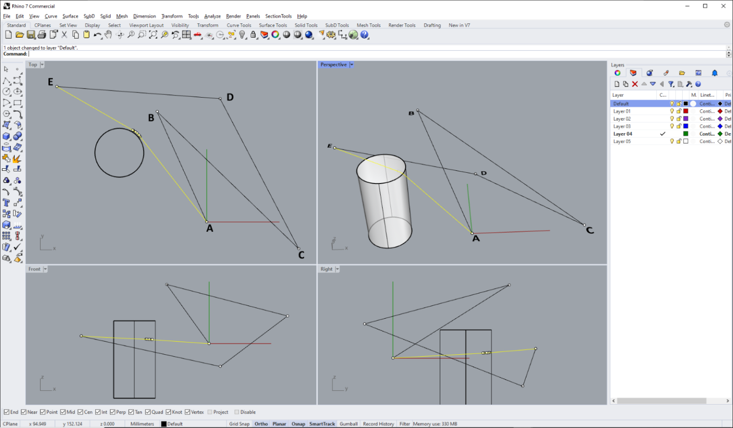
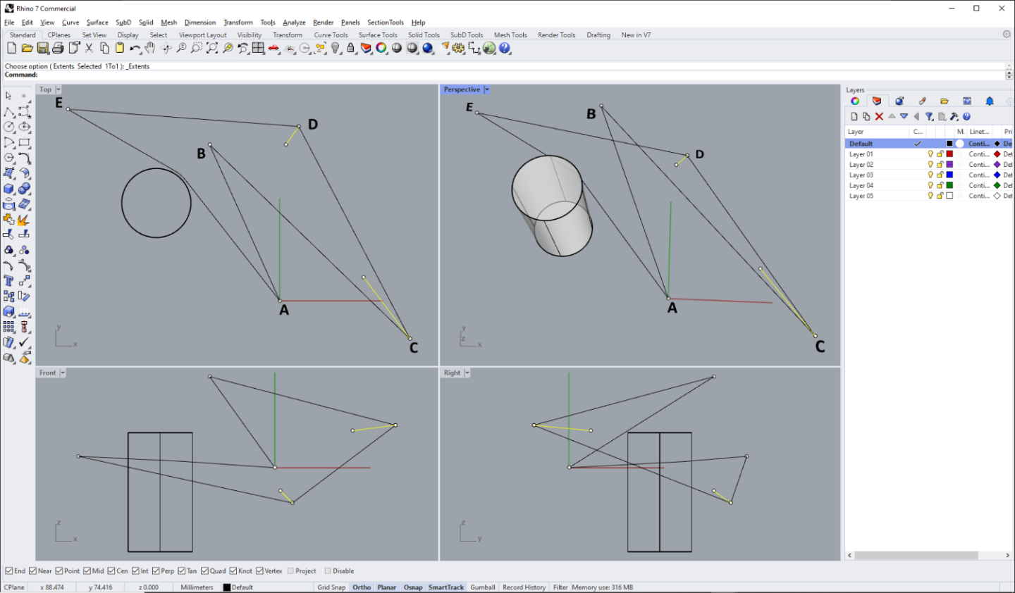
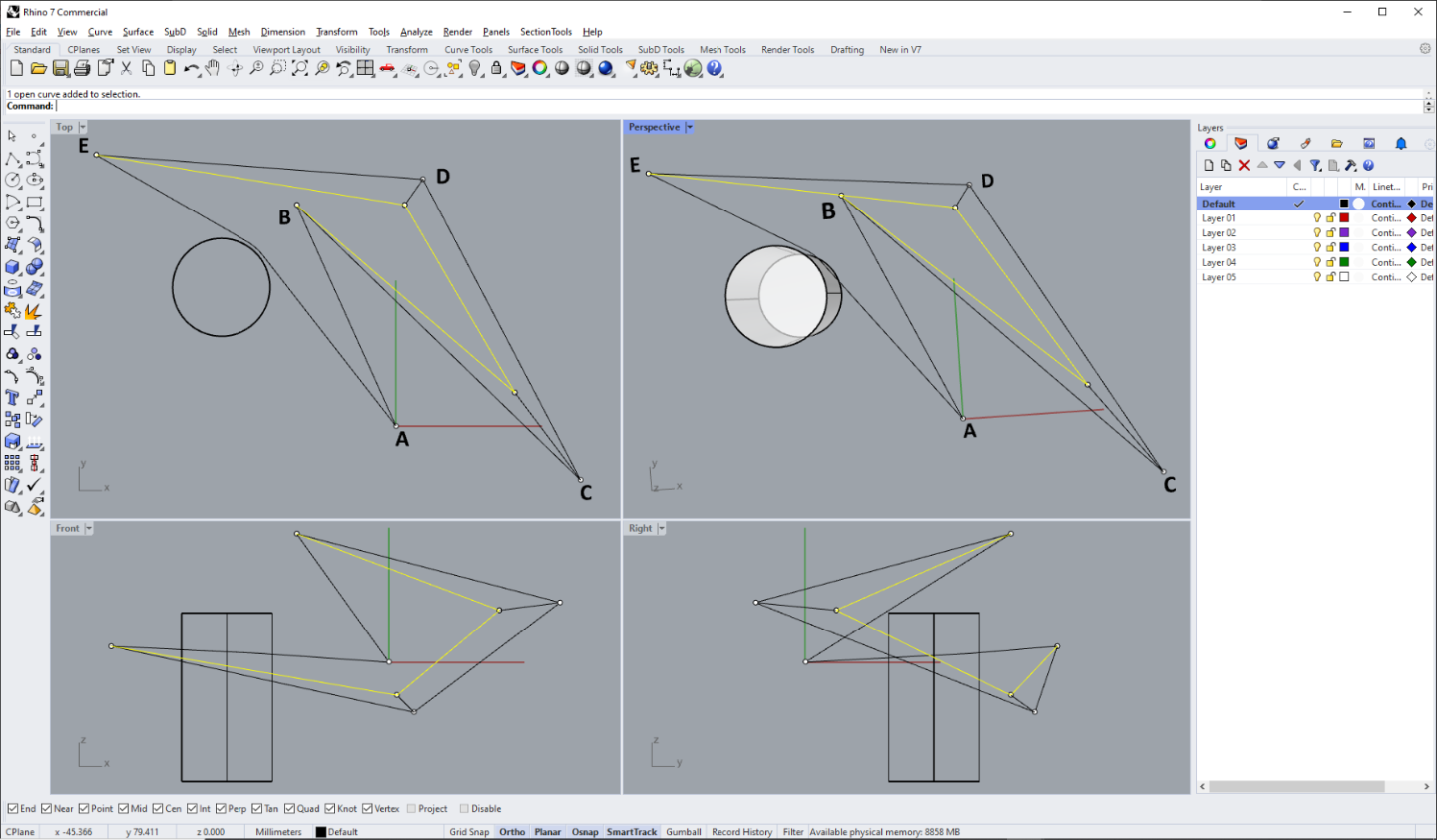
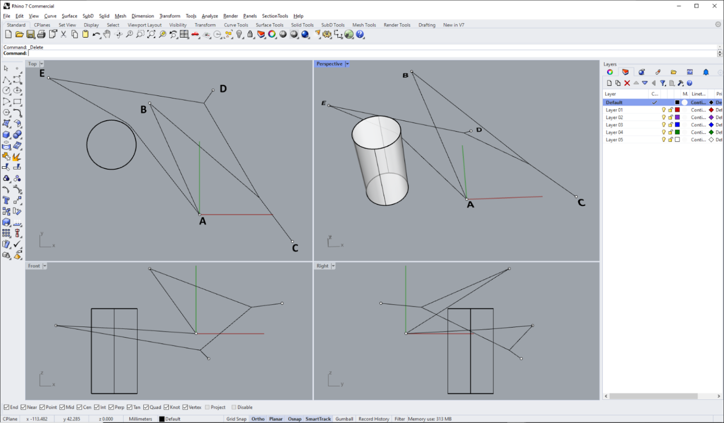
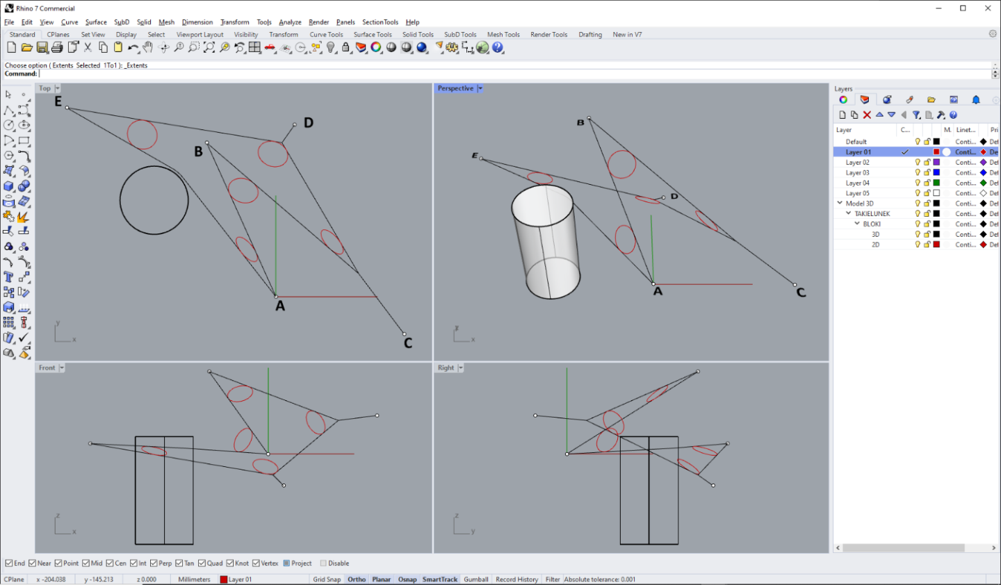
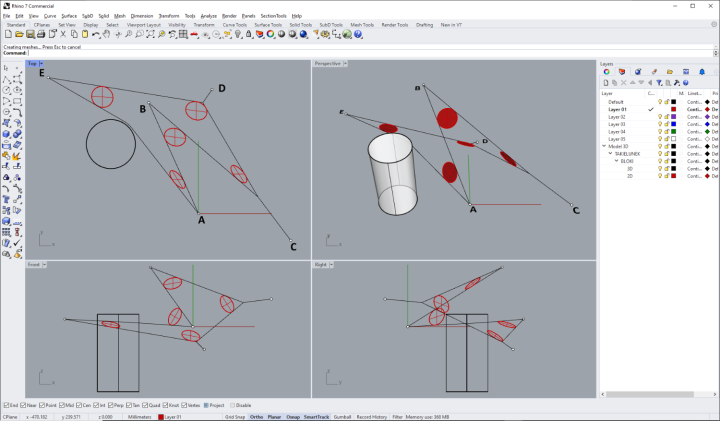
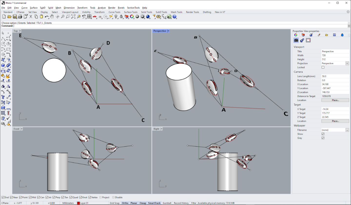
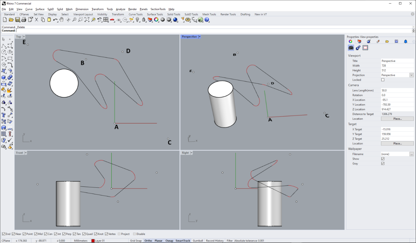
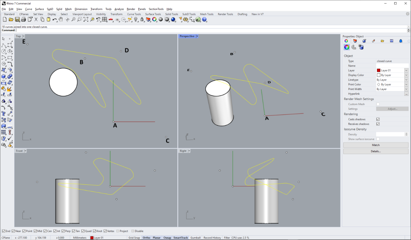
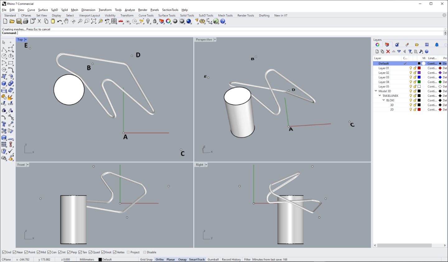
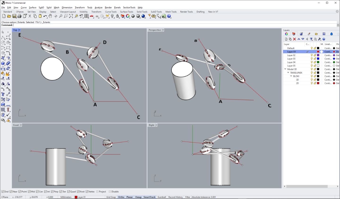
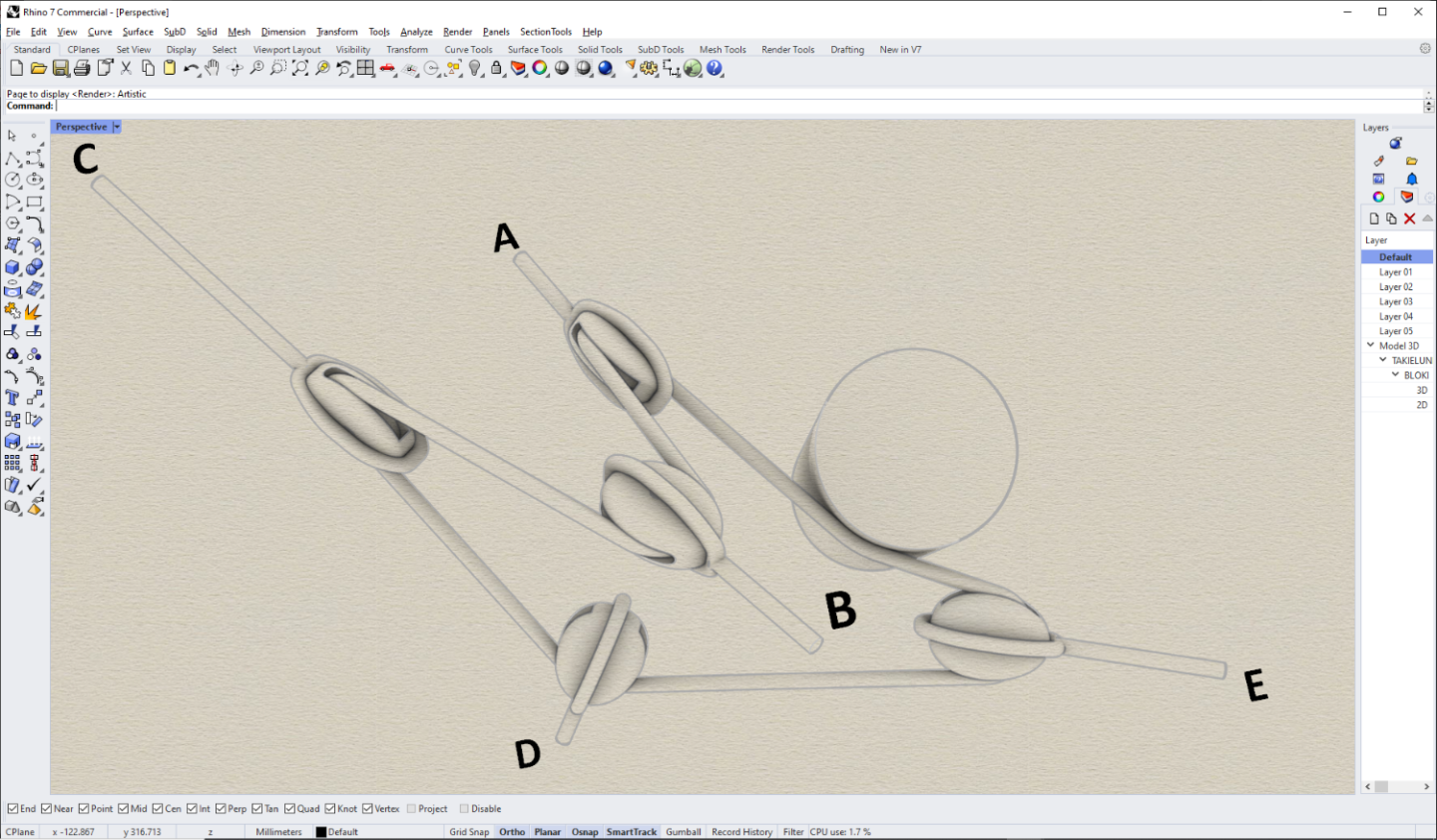
Persuaded by @scrubbyj427, who has been very supportive of my build log of the Sankt Georg 1627 3D model, I have prepared a short tutorial on positioning ship blocks in the 3D model space of a sailing ship. The methods shown are specific to the Rhinoceros CAD software. 1. Block preparation Define your ship block as in the diagram below (single block in this sample). The three visible red lines are the most important, i.e.: – the longitudinal axis of the block (red line segment), – the rope/fall axis around the sheave (red circle), – and the block’s strop axis around the block's shell (curve to match the shape of the shell). It is most convenient (and correct at the same time) to design the block modularly, i.e. by taking the diameter of the fall as one unit, the diameter of the block's sheave, say, 5 units, and the diameter of the red circle acting as a fall axis – 6 units. The 3D shape of the block's shell itself, its sheave and the sheave's axis are already less important in this method, but it is also a good practice to design them according to the art. Save this master block e.g. as "01. block single sheaved stropped", or similarly descriptive. In the diagram below, for illustrative purposes only, I have also drawn two green circles to symbolise the cross sections of the block's fall and its strop (these circles do not need to be saved in the block definition file). 2. Strategy for using/inserting CAD blocks It is best to insert blocks into the main file containing your 3D ship model as "Linked" and "Active" blocks, otherwise your main file will quickly grow to the size of Pacific and be unmanageable. Generally, you have two strategies to choose from here: (a) if you want to later count all the blocks used in your main file, taking into account their size, it is best to define a separate block for each combination of the block/rope type and size, and not just its type. This makes it very easy to do the model’s documentation later. In my case, six single block sizes came out, as follows: It means, that in this very case, each block definition (type and size) must be saved in a separate file, e.g. "01. block single sheaved - fall 1 inch", "02. block single sheaved - fall 2 inches" and so on. (b) if you only want to insert ship blocks for the show, then it is enough to define just one CAD block for a particular block type, without regard to its actual size. Later, after inserting it into the main file, you can scale it according to the thickness of the rope. In this variant, each instance of this block, regardless of the scaled size, will always have (in the “Block Manager”) the same name, e.g. "01. block single sheaved stropped". 3. Determining the initial run of the fall Connect the fixing points to which the block pendants will be attached to with the lines, as below. These are usually on yards, sails, stays, shrouds, belaying pins etc. 4. Obstacle bypassing along the way (optional) If there is an obstacle along the way of the rope/fall, the run of the rope needs to be adjusted accordingly. In this particular example, the cylindrical surface of the imaginary yard (grey cylinder) was extracted ("Extract surface") and then offset ("Offset Surface") by half the diameter of the rope/fall (here 5 units), resulting in a green cylinder. Green flat surface between points A and E was created, then "Object intersection" command was used to get a yellow circle. Next two line segments from points A and E were drawn tangent to this yellow circle. It was then trimmed (by "Trim" or "Split" command), and all these three yellow elements were joined ("Join") to get the corrected run of the fall: 5. Defining block’s pendant initial (approximate) length In some cases, there is a need to define the block’s pendant length manually, especially for obtuse angles (but not only). In this example, we will only do it for the points C and D. For the other points, i.e. A, B and E, they will be determined automatically. For this, use the "Line: Bisector" command. For the point D I have given a length of 50 units, and for the point C – 150 units of length. These are the two rather short yellow lines in the diagram below: 6. Correction of the fall run Connect the ends of these (temporary) pendants to the adjacent points (yellow lines in the below diagram): And delete some of the initial lines that are not needed anymore: 7. Draw the circles In this example, the diameter of the rope/fall is 10 units and the diameter of the rope axis around the block’s sheave (red circle in the block) is 60 units. So the circles with the diameter of 60 units were drawn using the command "Circle tangent to 3 curves", as below: And fill these circles with surfaces using the "Surface from planar curves" command, as follows: 8. Insert your ship's block as a CAD block (optional: if you are using the second strategy described in point 2b, then after inserting, you may scale the block to the correct size) Important: do not rotate the block after insertion otherwise the next command will not work properly. 9. Orienting blocks in the 3D space Apply to the inserted block the "Orient objects on surface" command: Base point: the center of the red circle in the block Reference point for scaling and rotation: (the right) end of the block's longitudinal axis (red line segment in the block) Surface to orient on: select one of your red circular surfaces "Rotation, Prompt" option in the command dialog window: ON Point on surface to orient to: center of your red circular surfaces Rotation angle: point your mouse cursor to the pendant's end or your fixing points (in this sample A, B, C, D, E) Make sure that "Project objects snap" is OFF, and "Center object snap" is ON. Delete the red circular surfaces that are no longer needed. 10. Trim all lines and circles (the latter drawn in point 7.) as below to get the final fall run. Delete temporary pendants drawn in point 5. (for better clarity, in the diagram below the blocks are temporarily hidden by applying command "Hide objects"): And join all these lines and curves together: 11. Make a 3D rope/fall using command "Pipe: flat caps": 12. Make the axes of the block’s pendants by connecting the ends of the blocks’ red longitudinal axis with the fixation points: 13. Make 3D pendants and 3D block strops using command "Pipe: flat caps": 14. Enjoy In practice, there can be more difficult cases, for example with double blocks, and then a bit of improvisation is needed, but the general principle is the same.


-
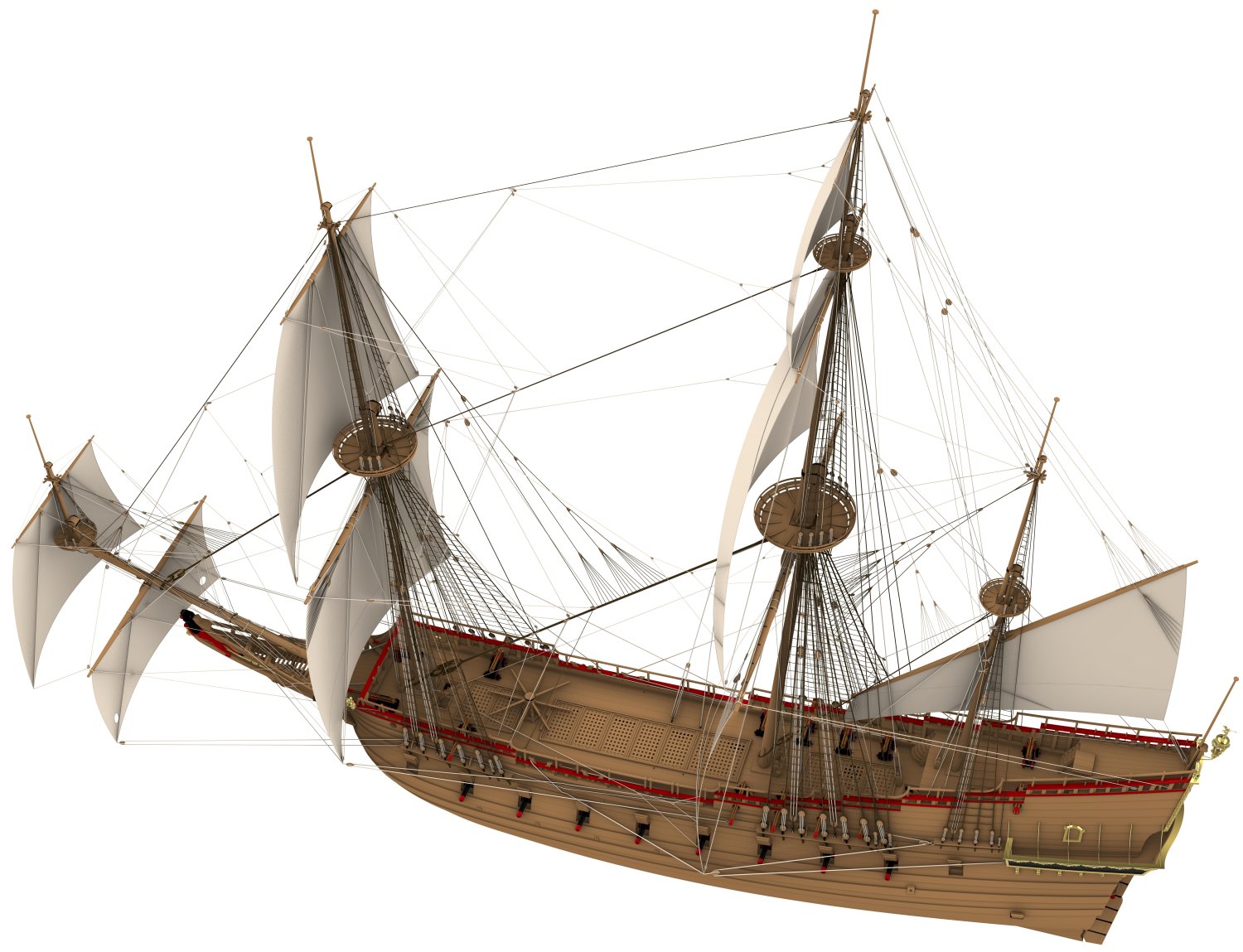
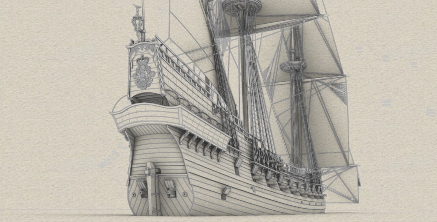
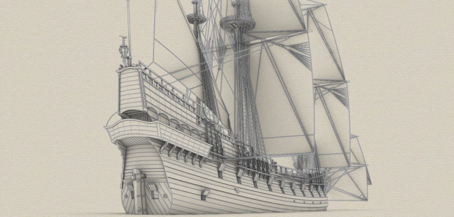
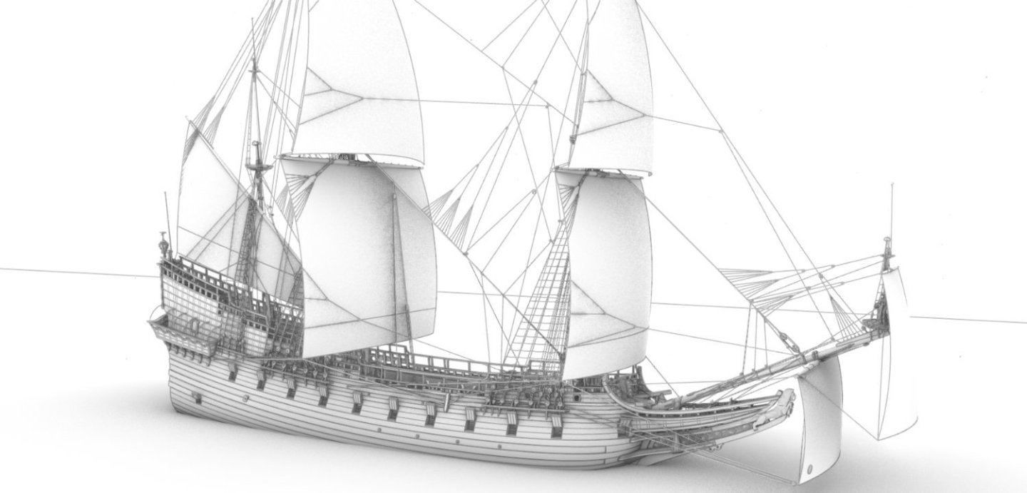
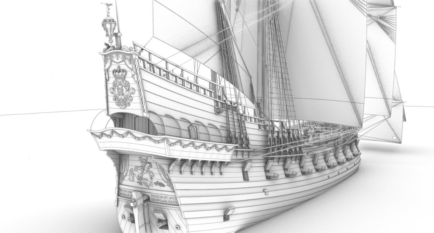
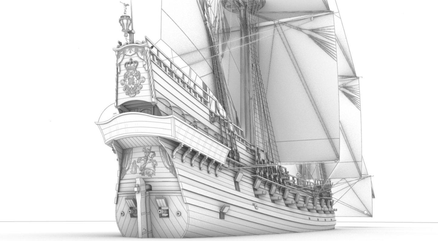
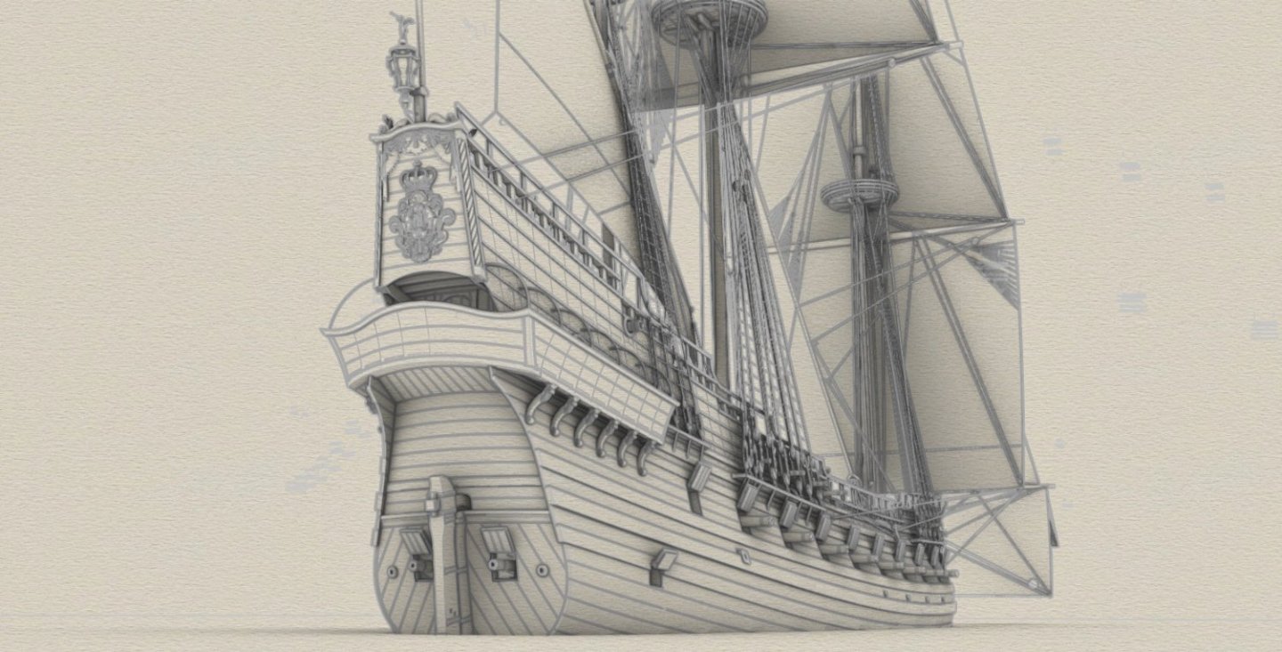
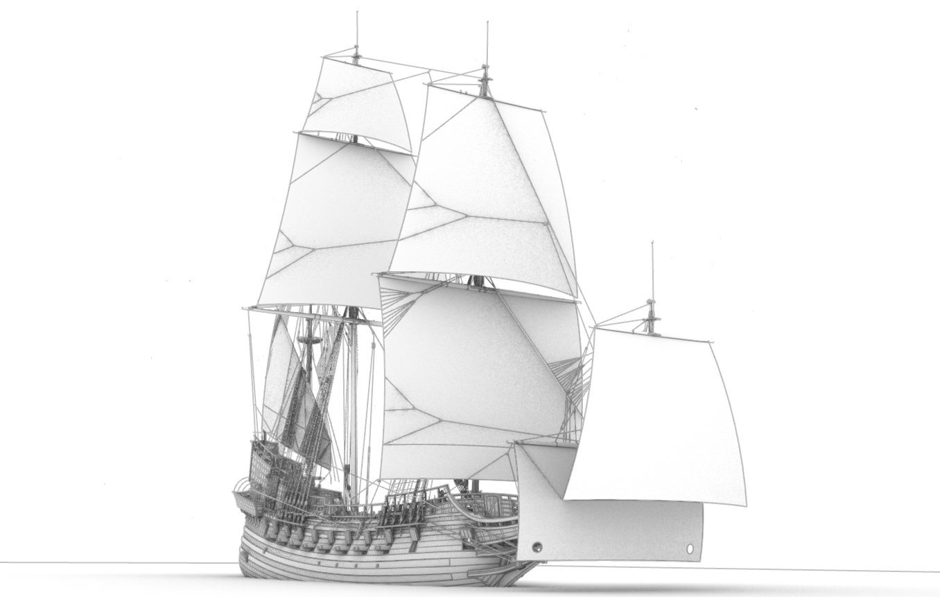
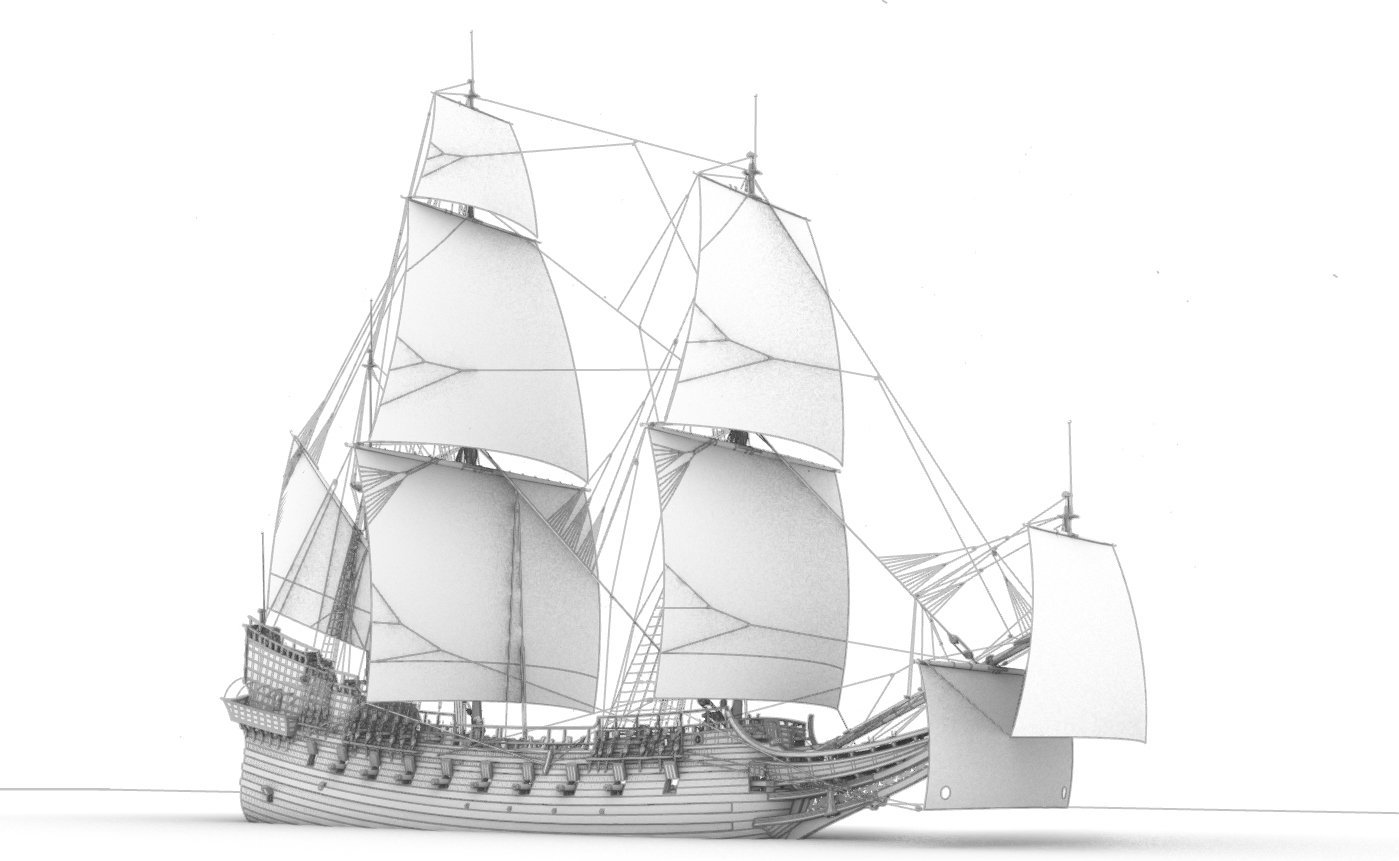
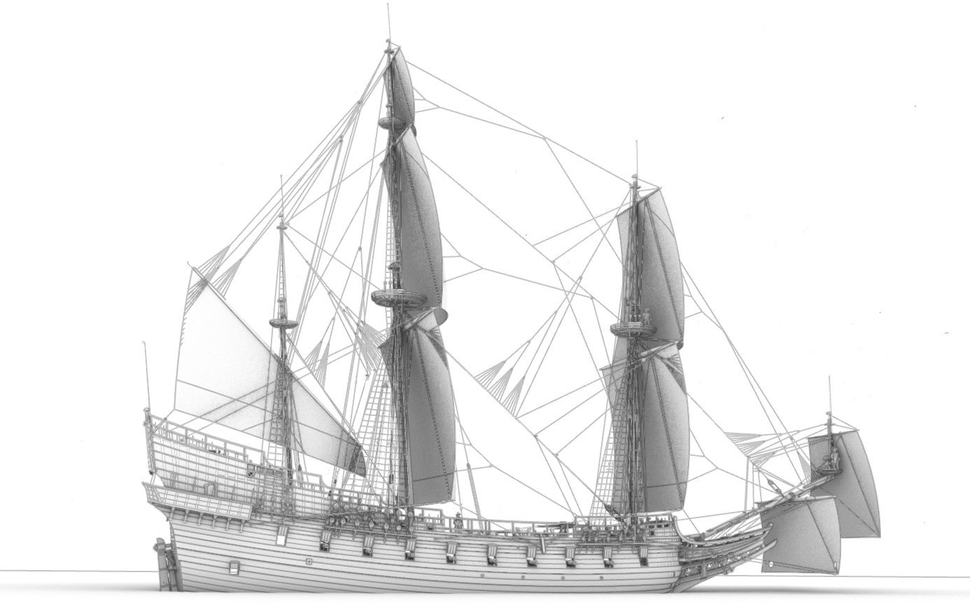
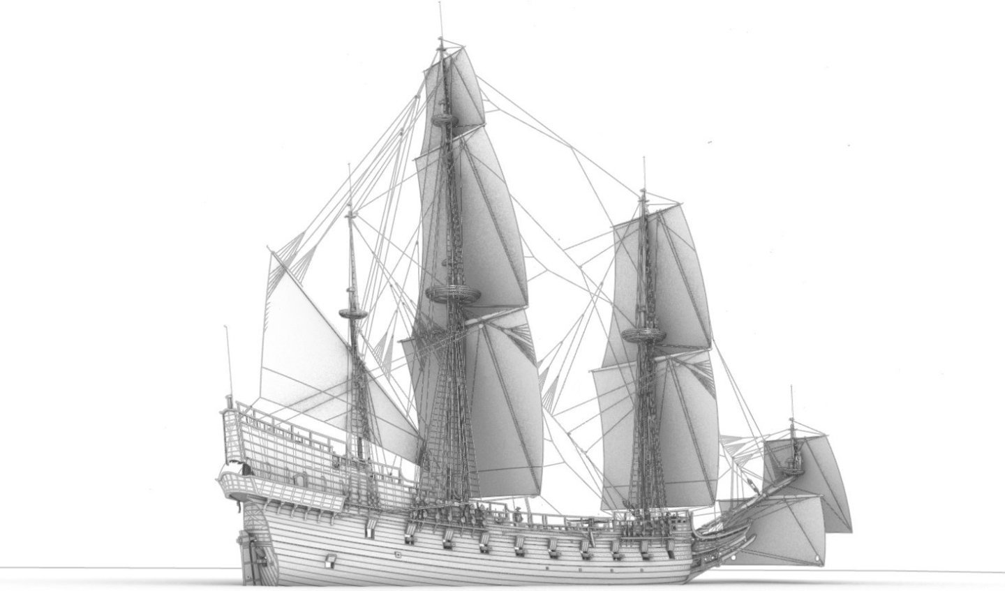
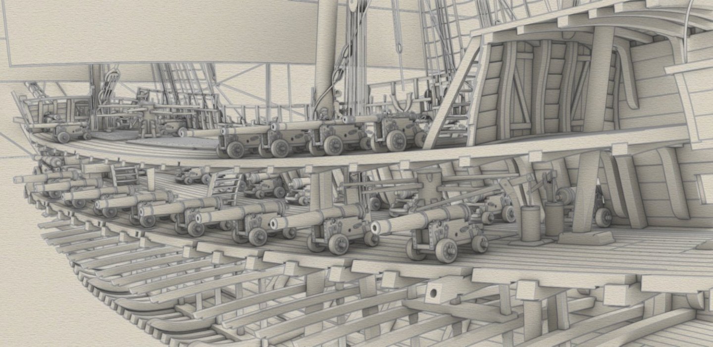
Scrubby, but you are absolutely able to create similar and even more impressive renders already in Rhino v5, because I just applied the material definitions without any specialized photorealistic effects that are already available in version 5 (hence such a rather sterile look, but enough as a color guide).
-
Scrubby, after all, you know it, all in Rhino, even without any software extensions, which I'm not fond of because they just hang the computer more often.... 🙂. Now I can do the manual for you that we talked about earlier.
-
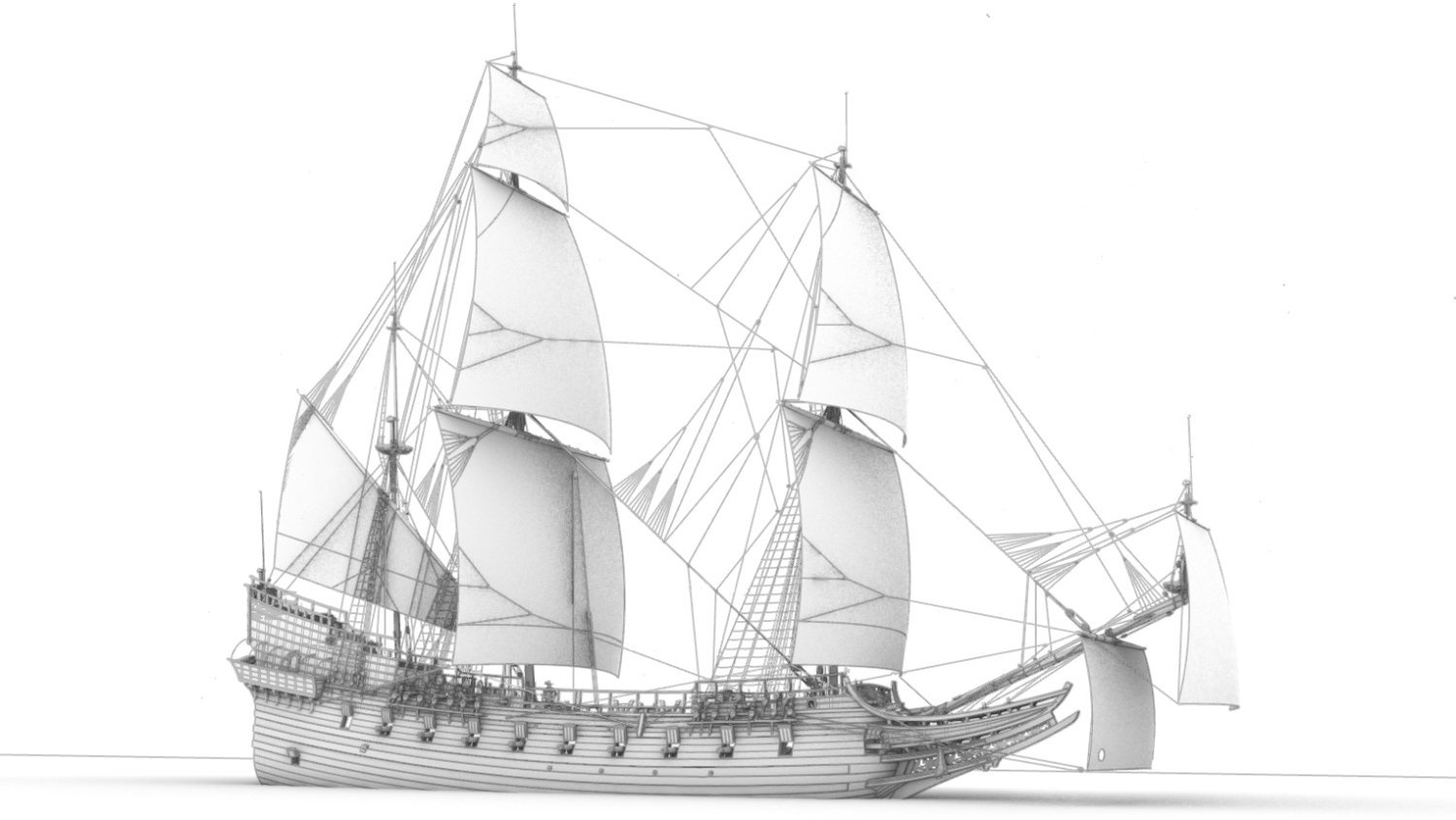
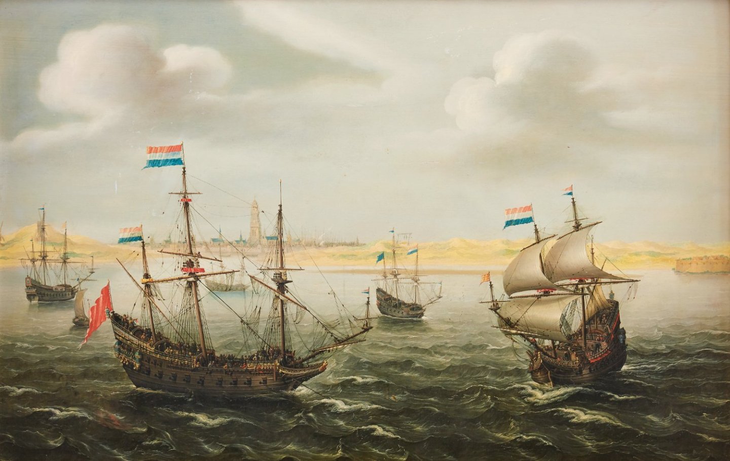
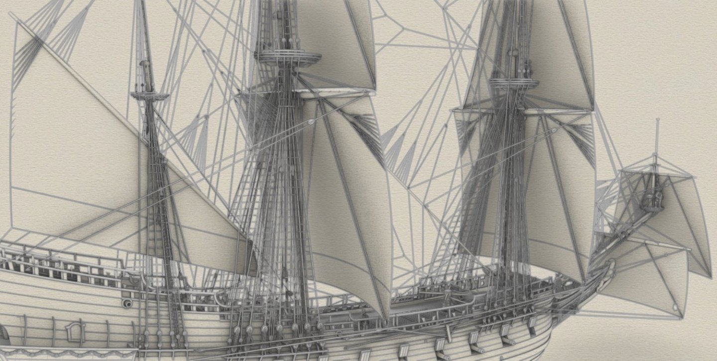
Rightly so, Marc, and this is shown quite extensively by period iconography. For example, like this image below. But of course, the decisive factor here was the set of sails listed in detail in the 1629 fleet inventory, which I have already referred to above. Not a single ship of the fleet has a mizzen topsail, some have main topgallant, and some have spritsail topsail. Men o’ war outside the coast with a city and a fort beyond by Cornelis Verbeeck, circa 1625–30
-
It's great that you're getting back to your preparations as the sailing season is near 🙂. You are rather on your own in technical matters, but what about adding one or two loooooong vanes (Flügel) on the mast's tops? They add so much charm to old sailing ships. And the best thing is that they don't need any additional control systems, as is the case with sails. 🙂
-
Okay, thanks at least for considering it. Under the watchful eye of Kirill and others, and with your common sense approach, I'm sure all will go well, as it has so far. I'm watching with interest too, as this is probably the only reasonably active build log from 'my' time and place at the moment. Good luck 🙂.
-
I was reminded of the words of Xerxes and Leonidas: – Our arrows will cover the sun. – Then we will fight in the shade.
-
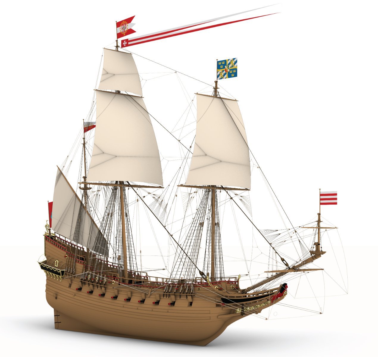
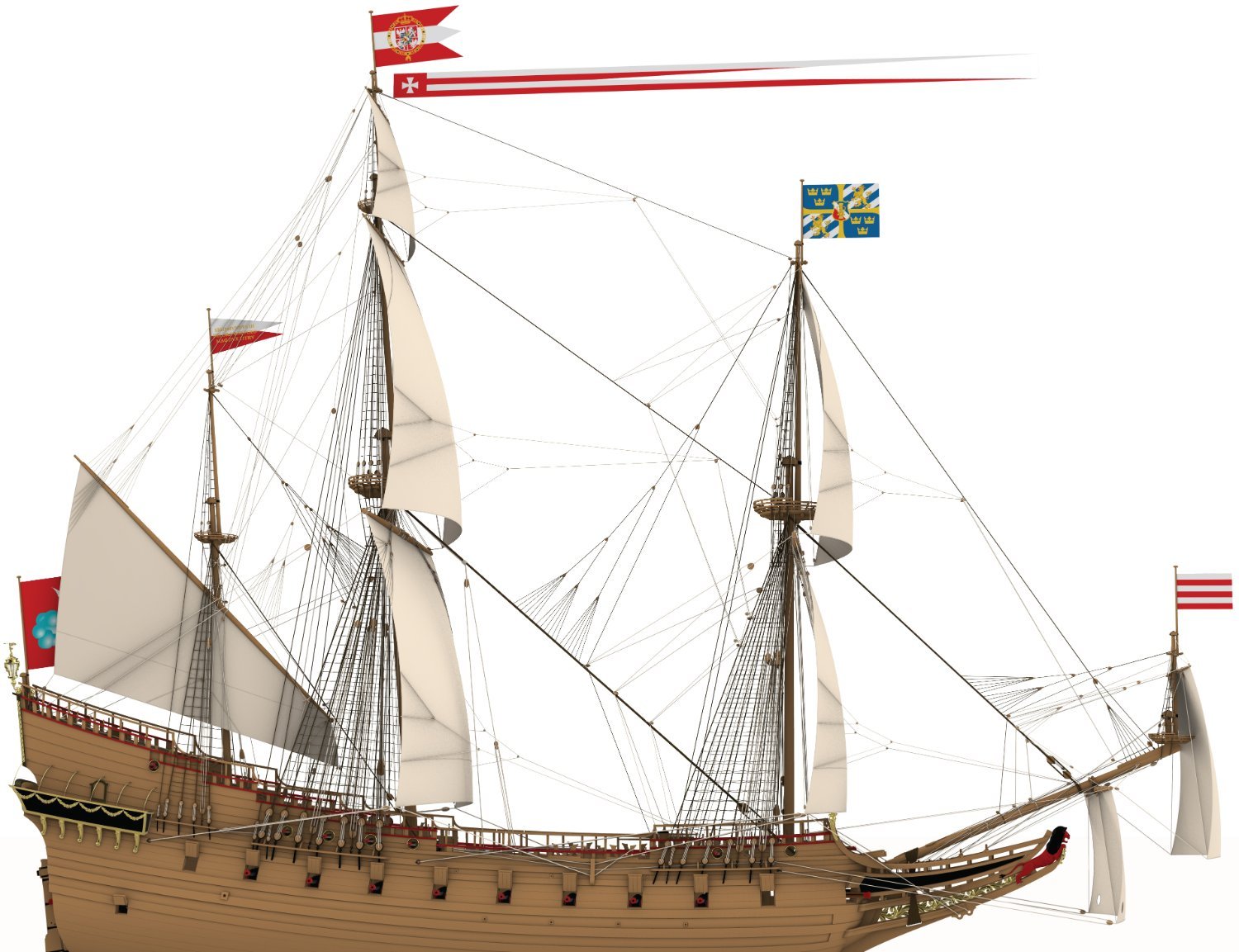
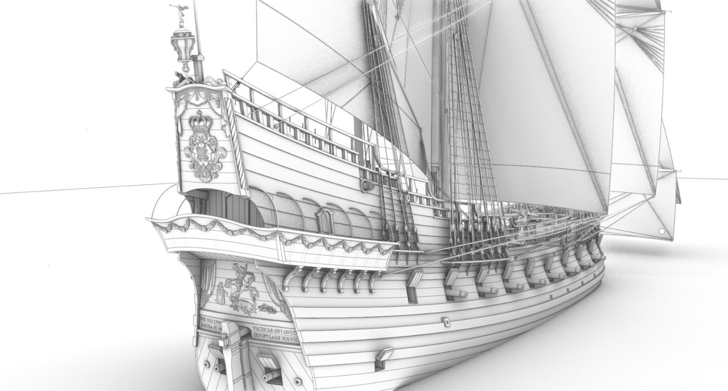
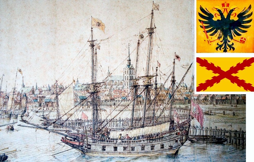
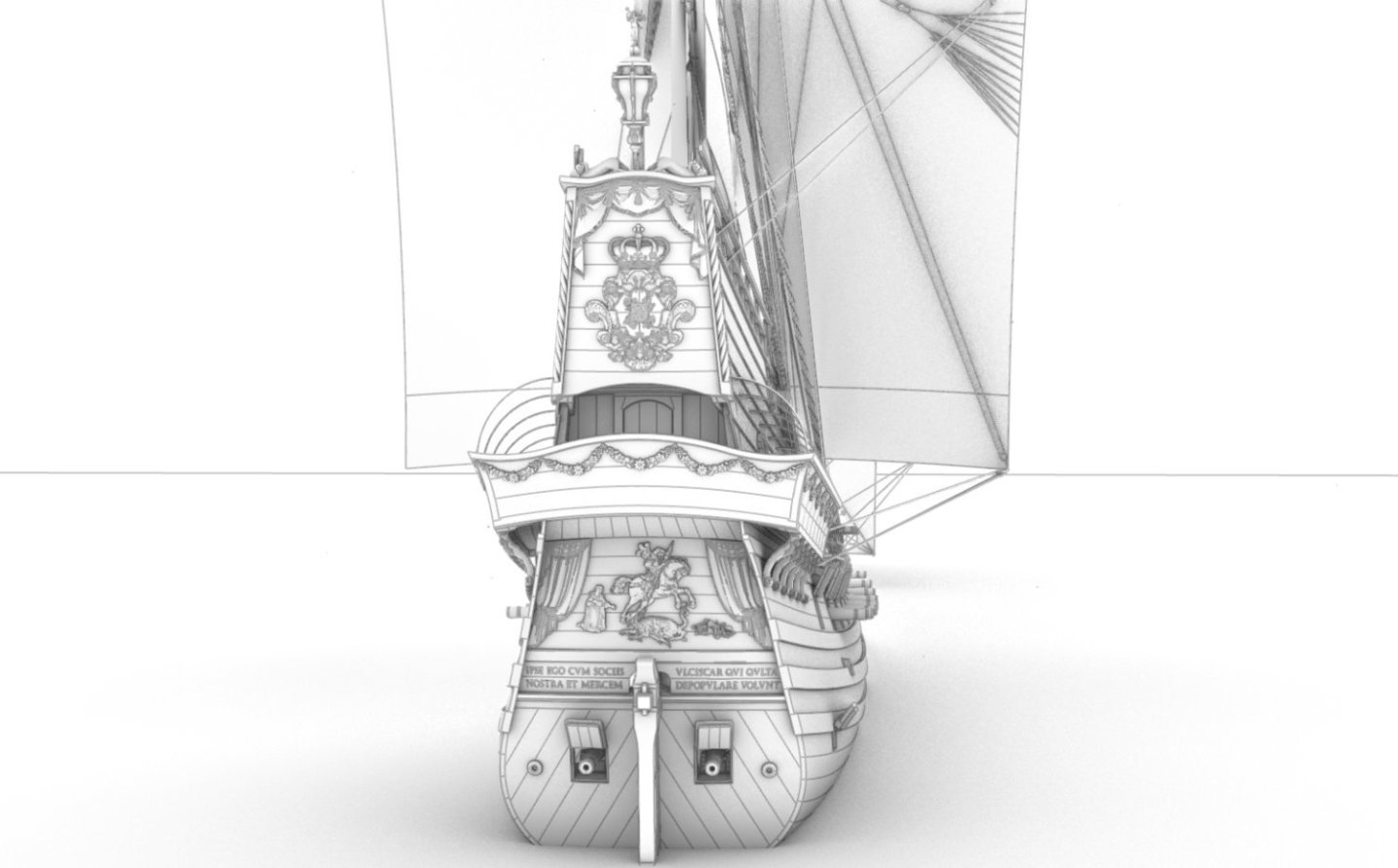
Vexillology for some is the least important issue, for others the most important. To be sure, a little more about this. According to the 1629 notarial fleet inventory, the admiral ship had the following set of flags: (a) „Zwo grosse flaggen, darunter eine Schwedische ...” (Swedish flag; for admiral ship only), (b) „... Die Andere mit dem Königl. Poln. Schwedisch[en] Wapen” (Royal Polish-Swedish Standard; for admiral ship only), (c) „Ein bluttfahne” (war flag/bloody flag; for admiral ship only), (d) „Ein flögel” (a vane; used on both flagships and non-flagships), (e) „Zwo kleine alte flaggen” (common flags; for both flagships and non-flagships), (f) „Zwen grosse Topstenders mit buchstaben” (broad pennants; for flagships only), (g) „Ein klein Topstender” (smaller pennant; for flagships only). Except small pennant, all of these flags are shown below on the St George 1627. Non-flagships were clearly not entitled to most of these flags.

-
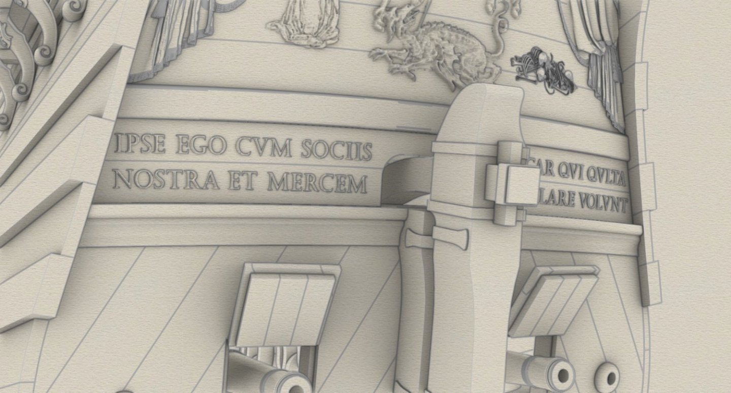
Flags, naturally. And here I have the presumably attractive information that the model of this ship can be built in two variants, also as the King David (the 'sister' ship of the St George), under the imperial colours and the overall command of Wallenstein, the general-captain of the imperial fleet on sea and land. For more on this, see the work Vergessene Flotten. Flotten und Flottenbaupläne im Heiligen Römischen Reich deutscher Nation vom 15. Jahrhundert bis 1632 by Karl Frick. Here, only that the entire fleet was (irretrievably) hired out in exchange for, among other things, the imperial modern infantry, which helped a great deal to halt hostilities in the region at least. For this the lower stern relief needs to be accordingly replaced, as well as the artillery set (for which written details are known). All other 'details' are, or may be the same. View of Wismar harbour, base of the Imperial Fleet (third decade of the 17th century)
-
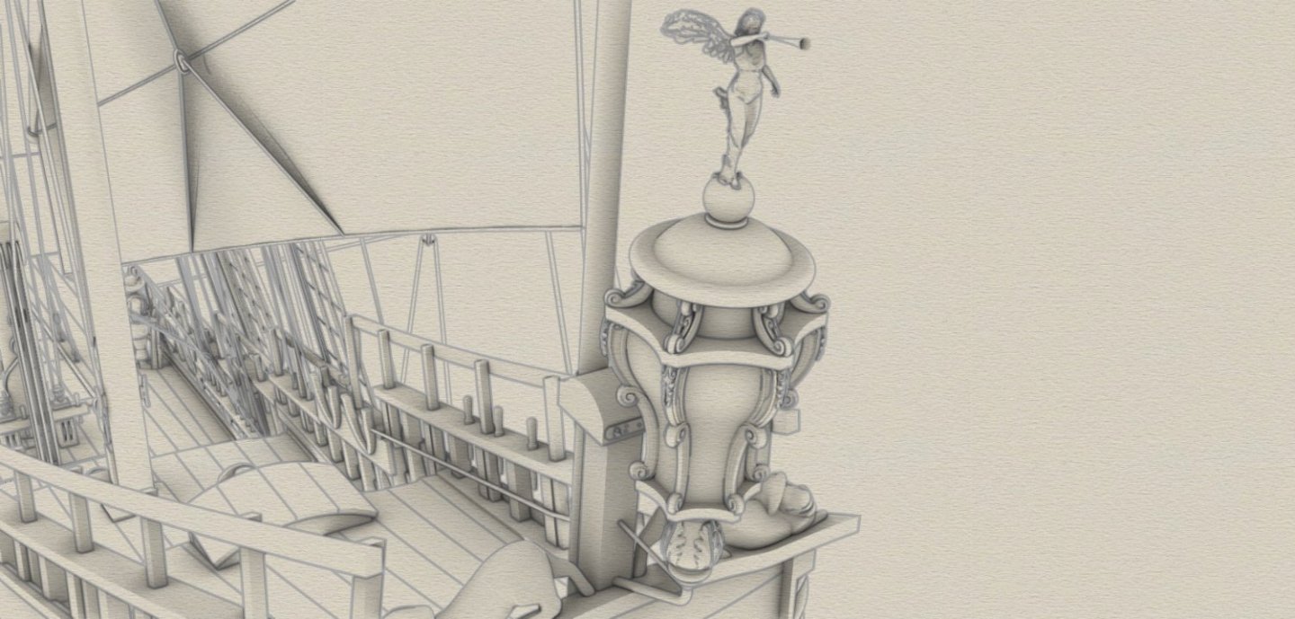
...very true. And the last warrior, meaning the last sculpture in the 'official' version of the ship's plan.


-
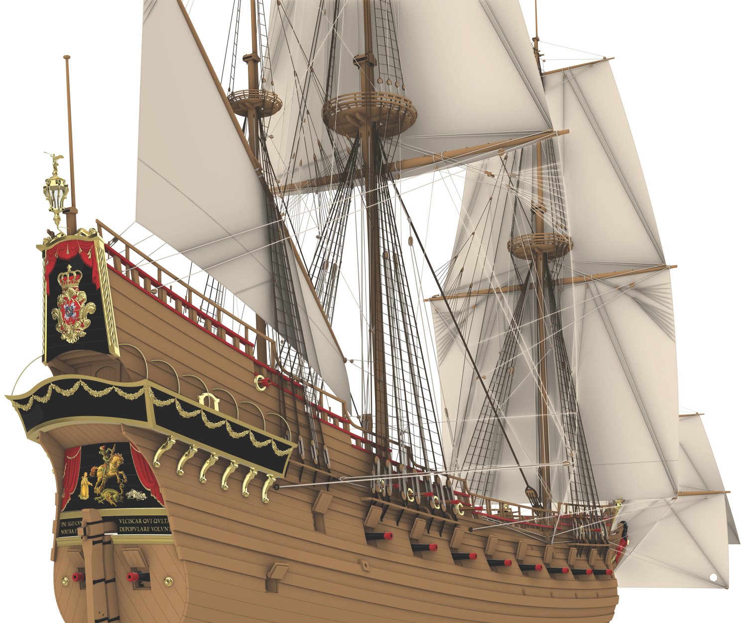
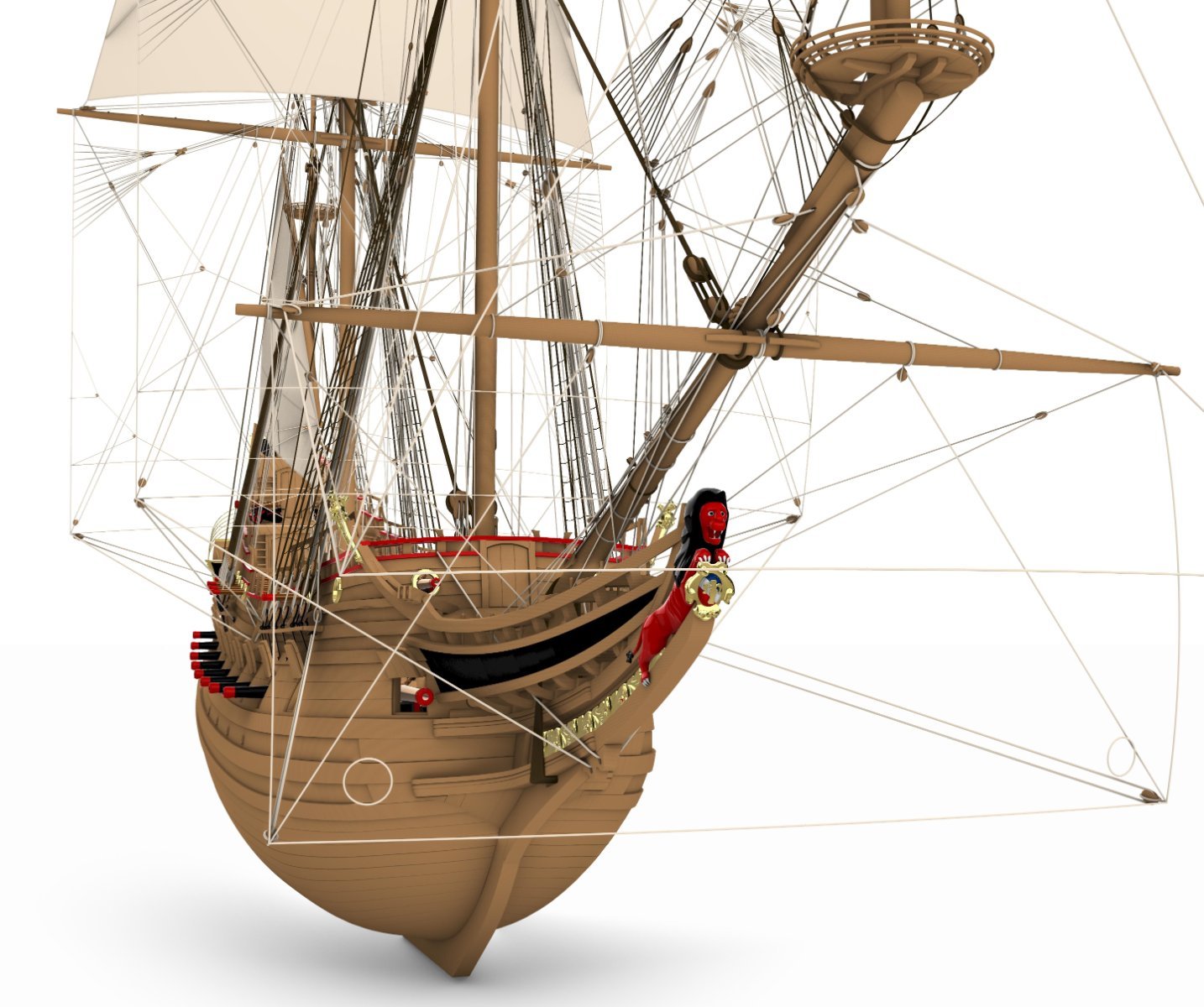
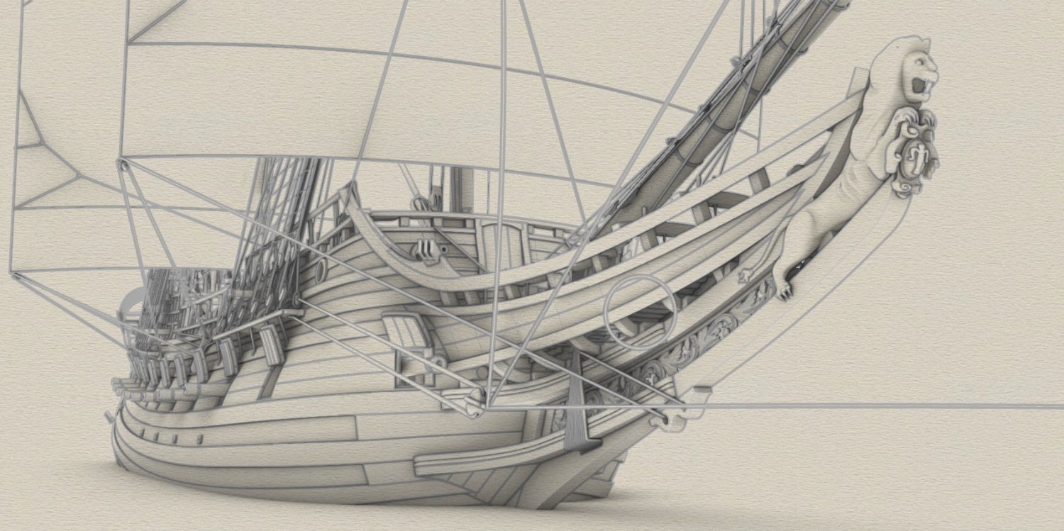
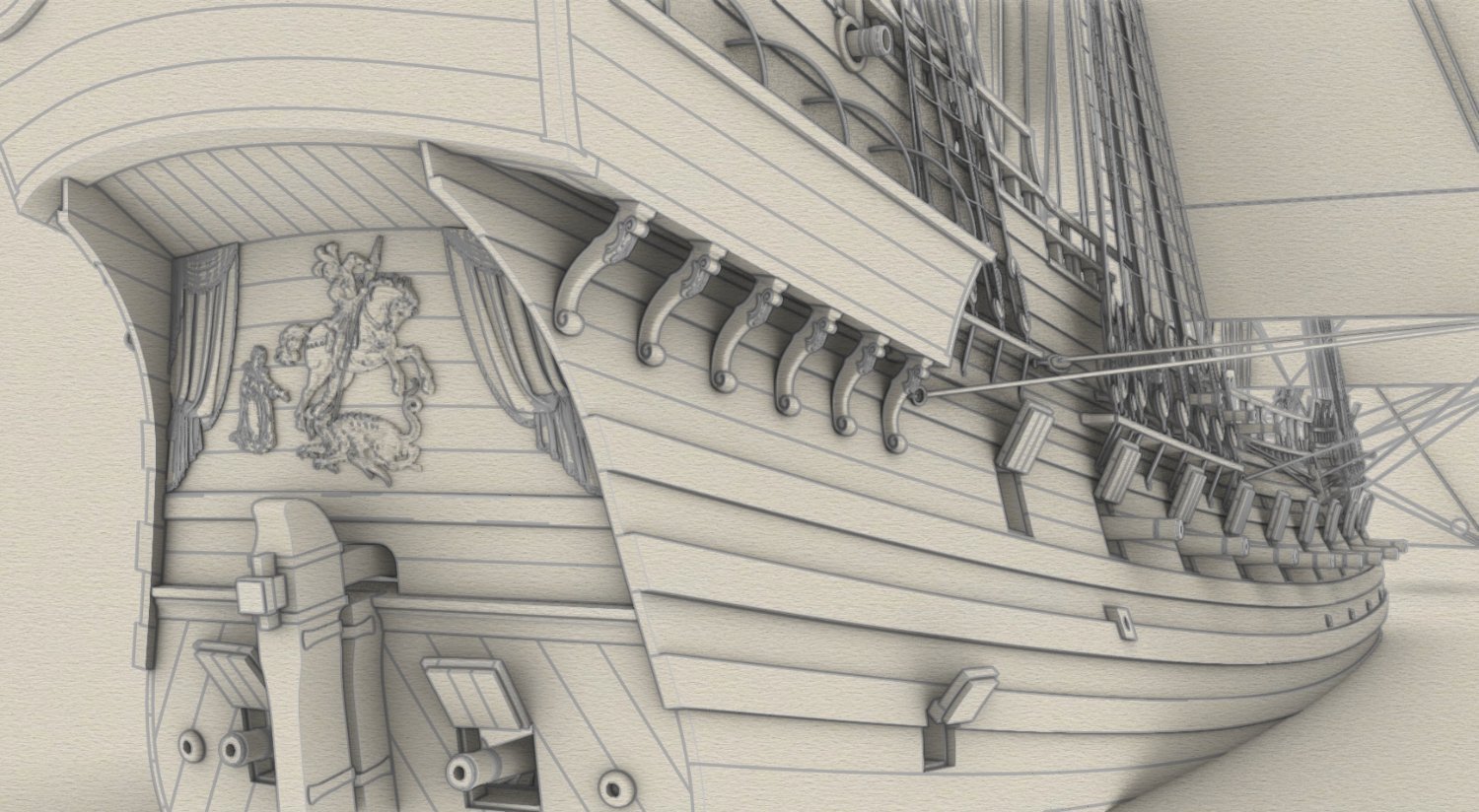
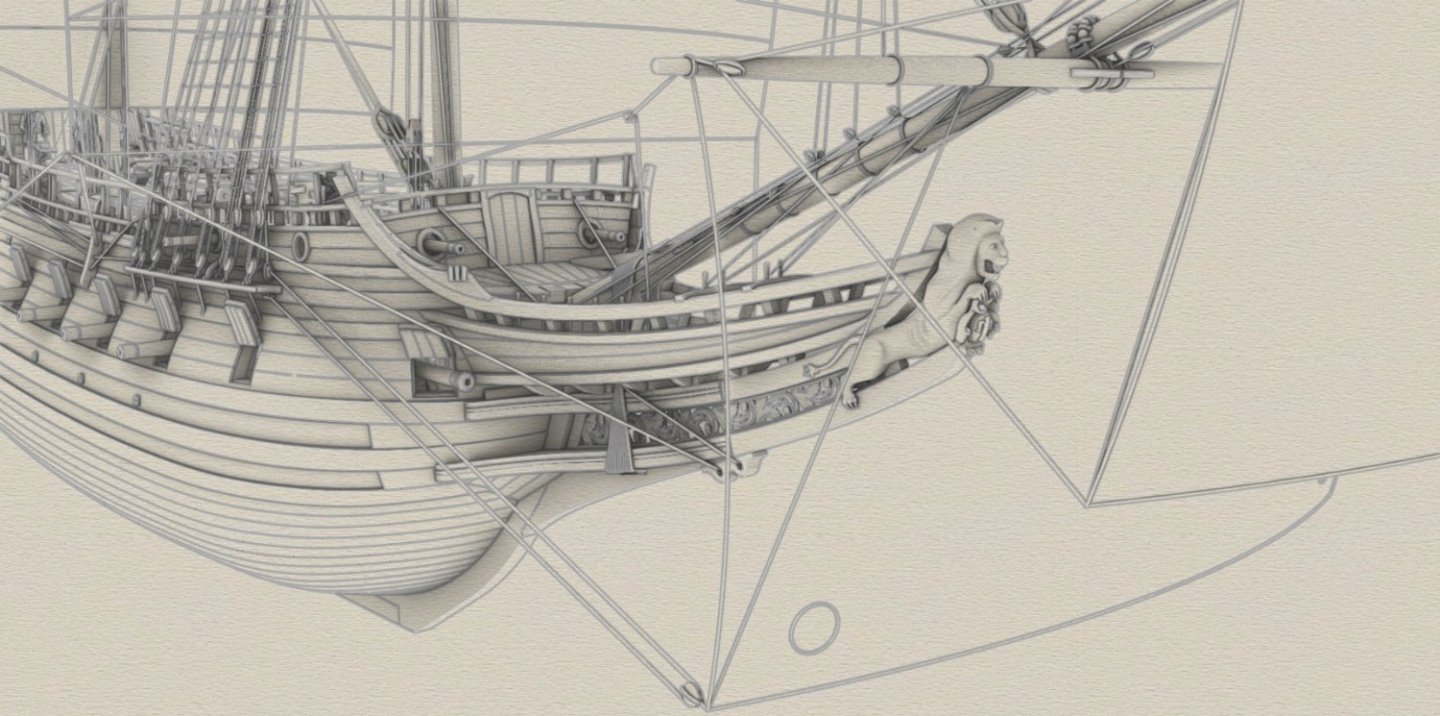
Thank you very much Montaigne. It would have been difficult to explain it more clearly, and I read it with interest myself 🙂. * * * While the royal coat of arms on the stern has all the heraldic elements (i.e. the emblems of the two kingdoms, Poland-Lithuania and Sweden, and the emblem of the ruling house; all of these on three different levels), then the figurehead beast just holds in its paws only the symbol of the reigning Vasa dynasty. By coincidence, or rather by the course of history, this symbolism is identical to that of the Vasa 1628 ship.

-
@Metaspace Roman, thank you very much. I will treat this question as rhetorical, otherwise I would have to tell the story of half my life. If you're going to start, my advice is not to put it off, as it's a long and bumpy road. @Martes This was supposed to be an asymmetrical composition, but you're absolutely right, it came out overly asymmetrical due to my initial reluctance to include the practically obligatory pile of bones seen in most period paintings. I have made the appropriate adjustment and now compositionally it does indeed look much better. I have also added a few other elements and the design of the stern decorations can be considered complete.
-
Only the last-minute arrival of the cavalry saved the lady from misfortune.

-
Due to dynastic issues, the royal coat of arms of this period was a quite complicated affair.

-
With Martes' active help some of the ship's decorations are being made, but only such a model of the stern lantern was available at the lantern booth in 1627 fair, and modellers today will be rather unhappy. Then again, neither are my computer's processors and fans.

-
Hello again, Don't know if you will be interested in this, but I have a suggestion. It's about martnets, which you may want to replace with both functional and iconography-compatible ones: make a combination block (i.e. euphroe-single sheaved block) as in the diagram by Ab Hoving below. Look at the graphic in my post #213 on St George and replace everything you will see against the sail with your new block. The double block fixed to the stay (or to the fighting top) remains. Done. It shouldn't be any great earthquake.
-
@Montaigne Probably from version 5 onwards, Rhino has an Edge Softening feature that can at least partially replace filleting for renders, without doing the actual filleting. I used it some time ago with very good results. @Ondras71 Thanks a lot. I like to think that I'll be able to prepare commercial plans soon, and that you and your modelling diligence will look at them with a favourable eye.
-
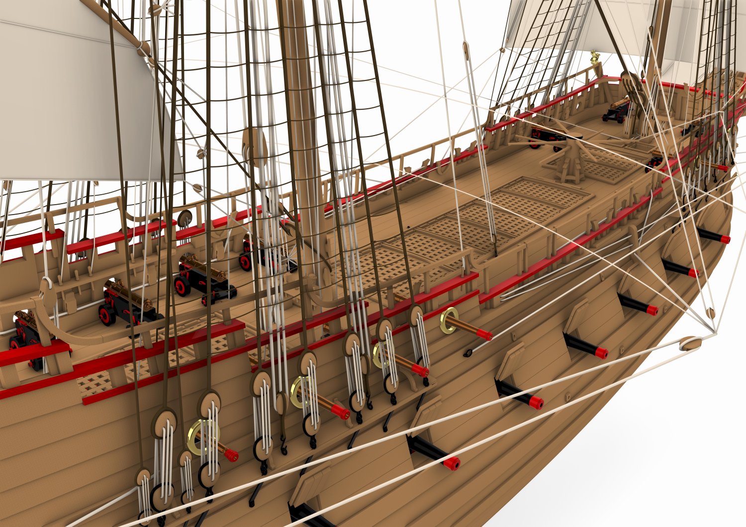
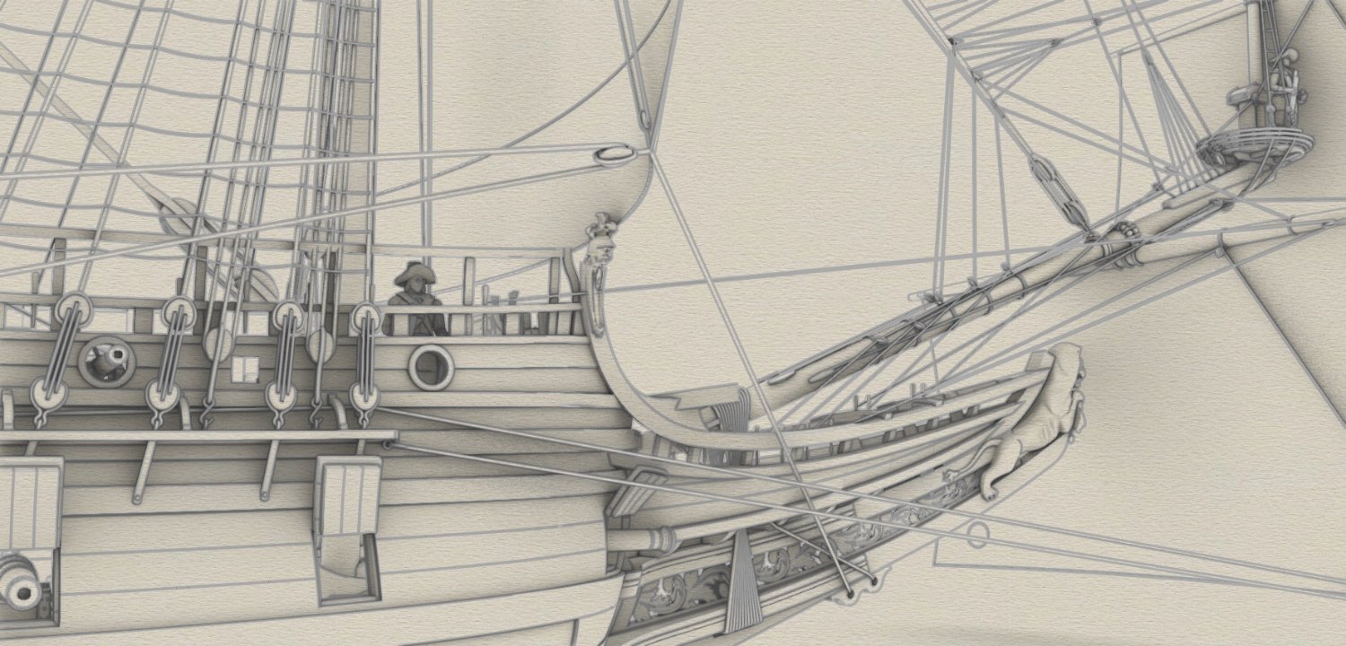
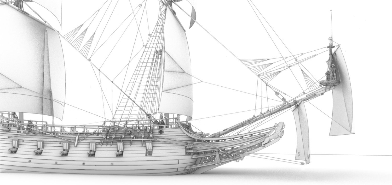
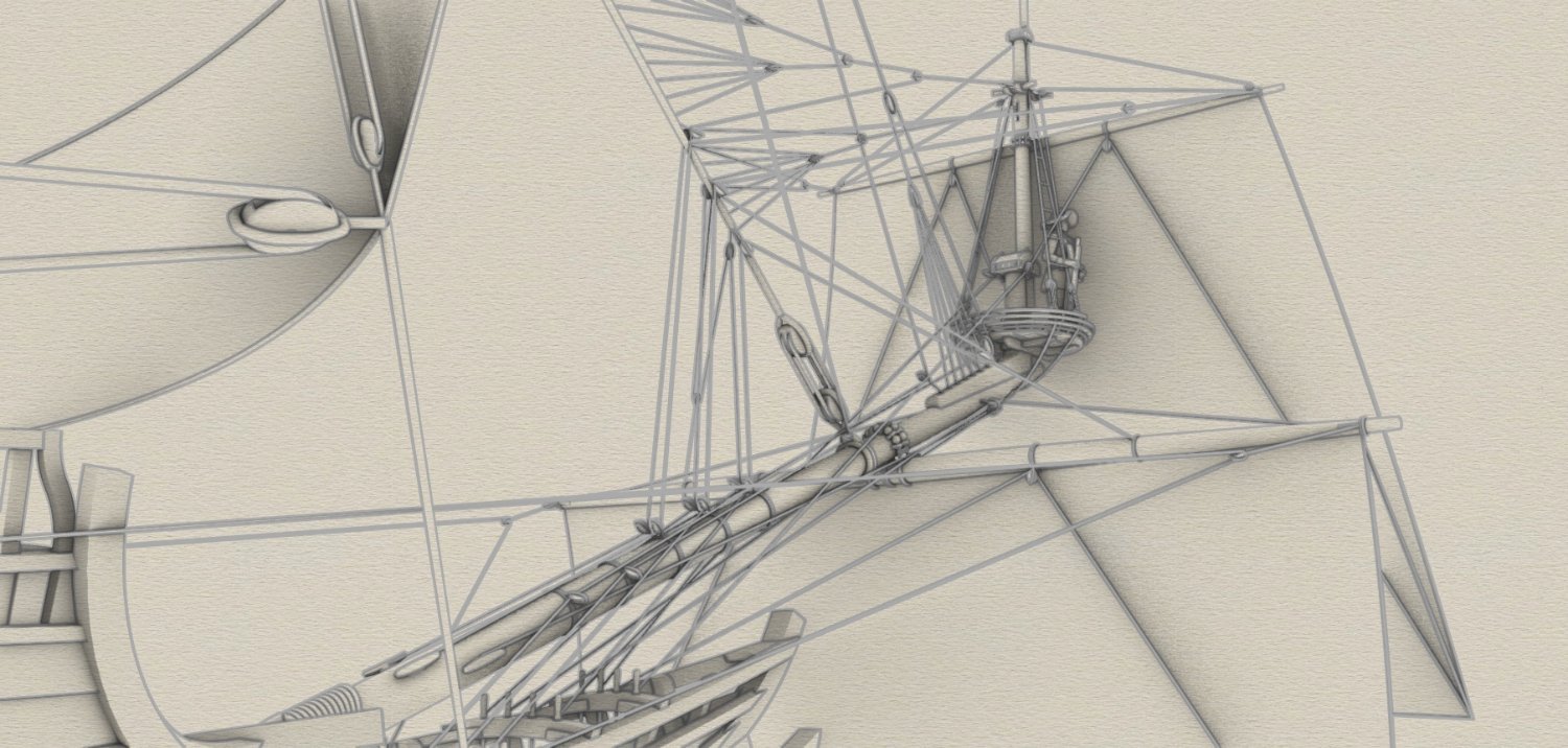
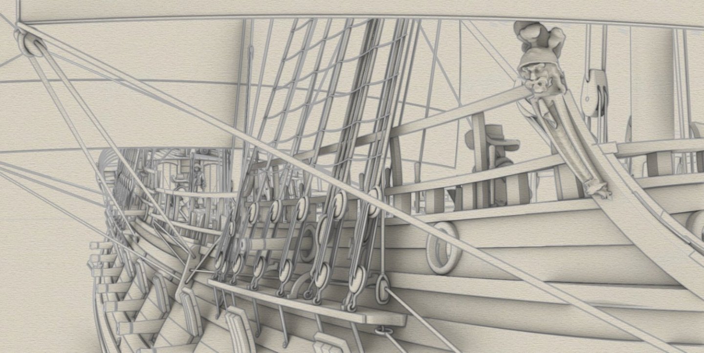
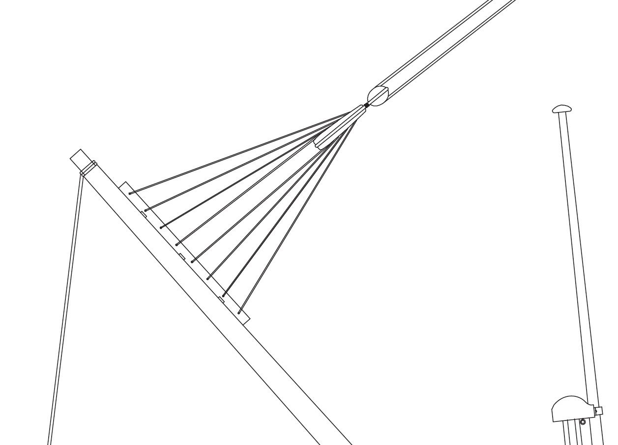
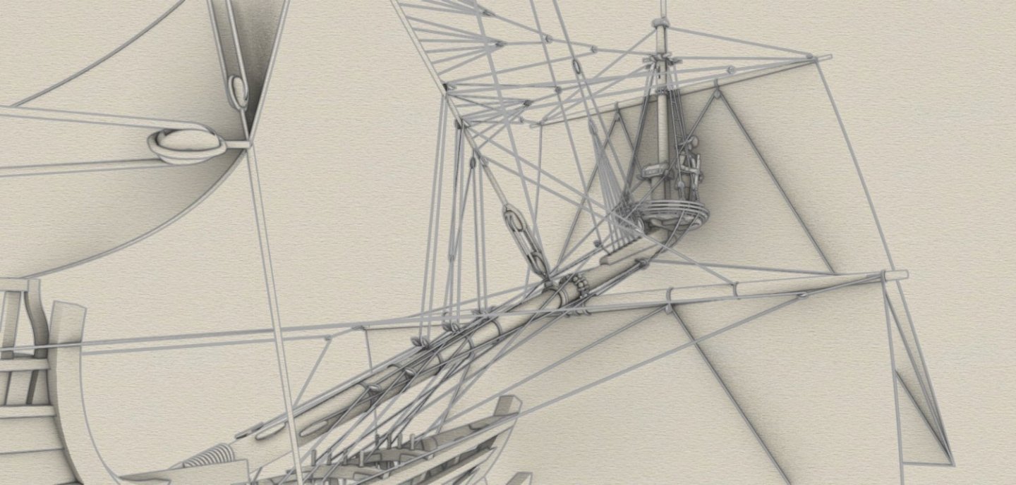
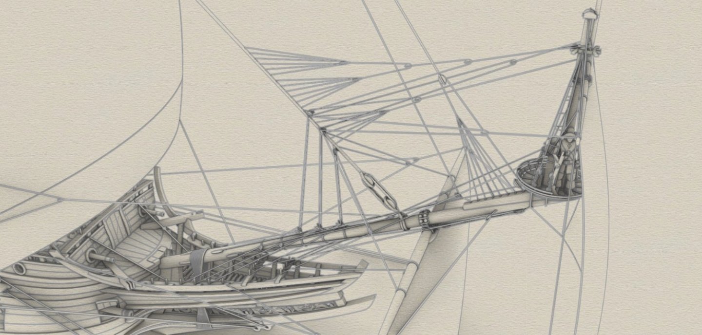
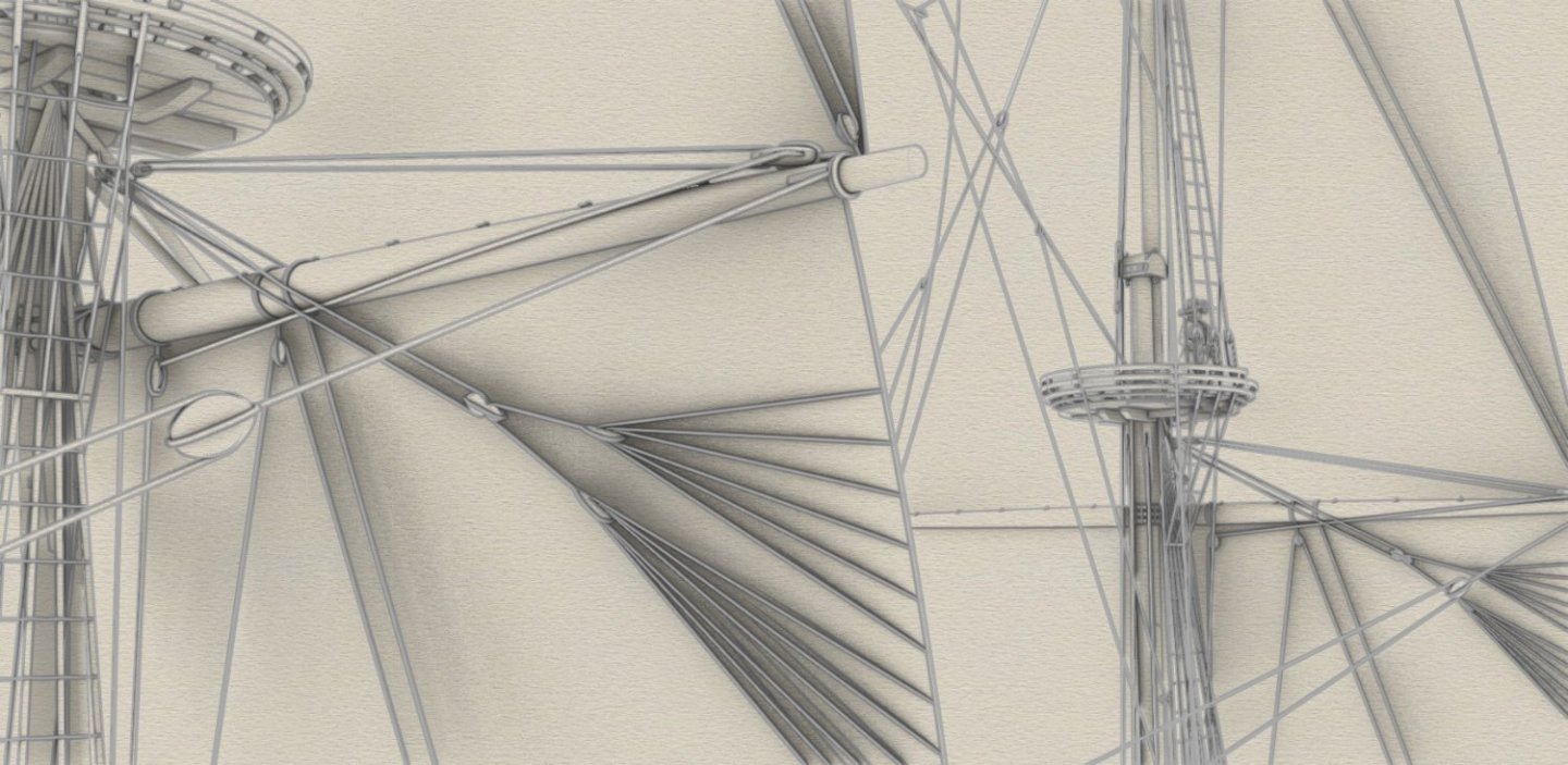
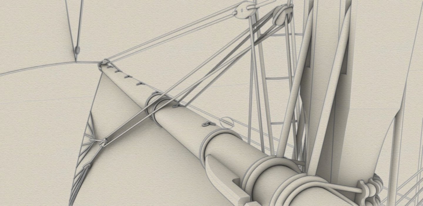
The rigging can be considered finished unless someone points out an anachronism worth improving (one side shown). There is little time left for this, as only the decoration needs to be designed now. Bowsprit rigging in all its 'glory' (i.e. both sides shown): And this render found its way here quite by accident:

-
When it comes to chamfering and filleting, I try to use these only exceptionally. Basically for larger pieces and/or in situations where it can no longer be avoided, e.g. for knees. And in fact I always chamfer/fillet just one edge rather than all of them of one solid; fortunately the specifics of the project allow me to do this. Primarily because filleting/chamfering, widely applied, would increase the file size, complexity and handling time (e.g. rendering) many times over. Also because subsequent modifications of chamfered/filleted elements (as opposed to unchamfered ones) require much more time and effort. And there probably isn't a single part that I haven't modified three, four, five times and sometimes many more times... It is for this reason that I try to keep backups of the parts before applying filleting or chamfering, but this also complicates the task in itself.
-
Thank you very much Fred for your comment and information! In the case of the Ann Royal, joining these pairs of single blocks together (as was sometimes done) would virtually give fiddle blocks, and a trivial euphroes from some arbitrary pieces of wood could have been successfully made even by a novice ship carpenter. This would have given exactly the set of blocks I came up with for the St George. Well, it may not be the simplest arrangement, but after all, one can also come across even more elaborate ones on the pictures. I would also add that information from you, on this issue or any other, is always among the most valuable. Thanks again, Waldemar
-
Hello Ron, Not much data available for the first half of the 17th century. Apart from the well known work by Adrian Caruana, The History of English Sea Ordnance 1523–1875 with rather sparing information for this difficult period, there is also Journal of the Ordnance Society which you may investigate. Be that as it may, any existing sources were also certainly explored by Richard Endsor and the resulting interpretation presented in his works, which are all too easy to find on the web to list them here.
-
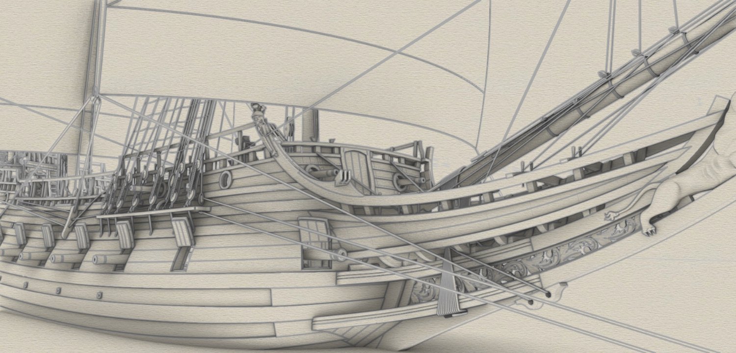
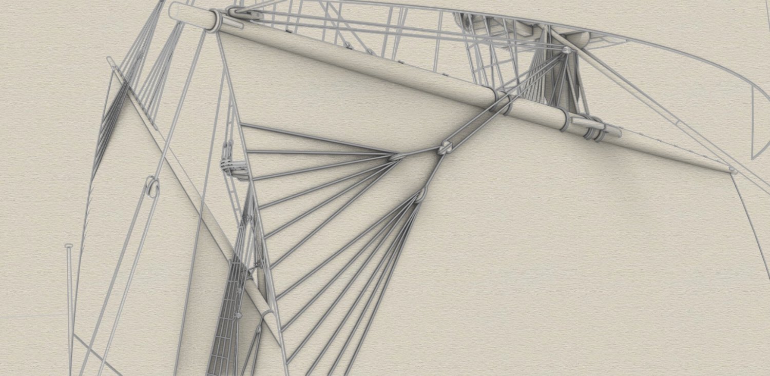
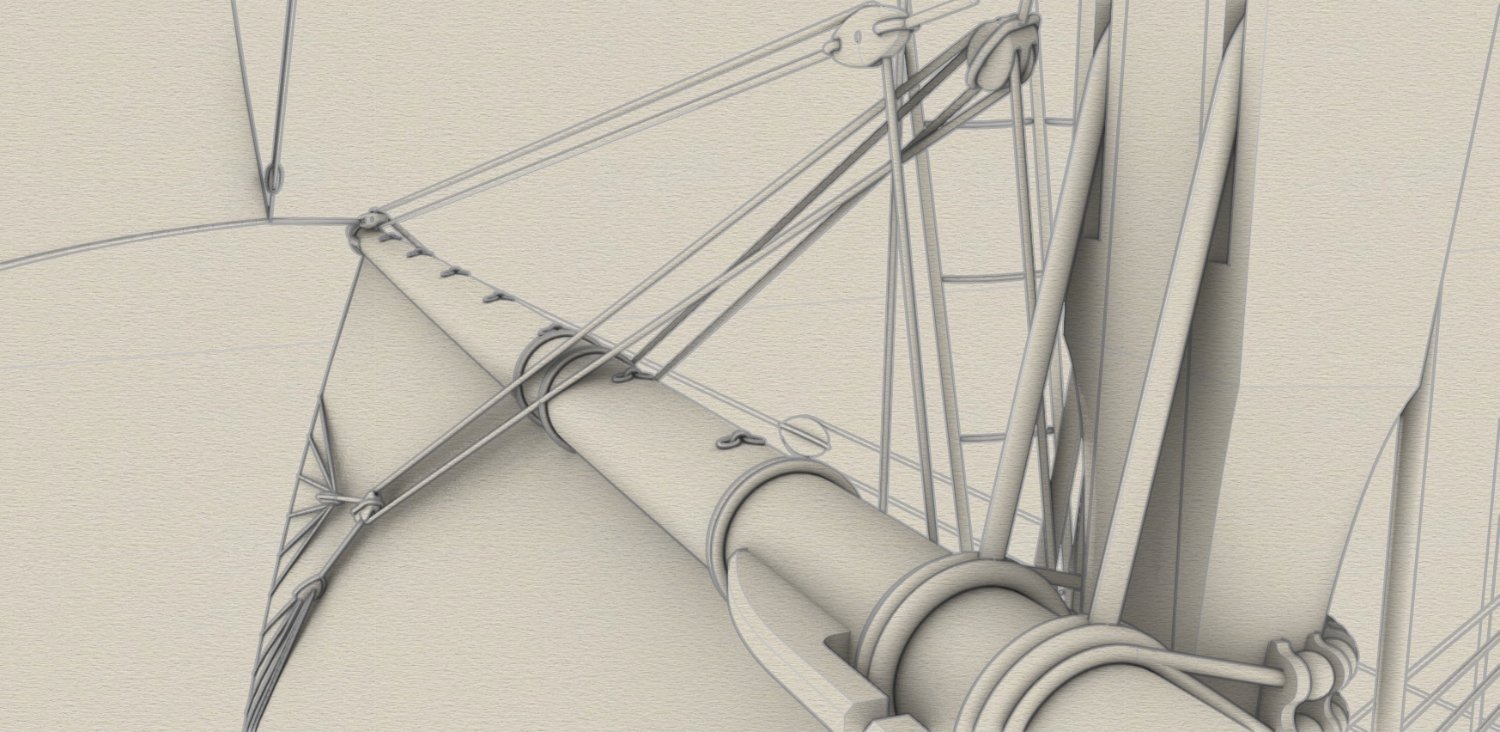
Bowlines and Martnets. Mysterious martnets deserve more commentary because the configuration shown here, reconstructed by me on the basis of period iconography, was used here for the first time. With regard to this item, other modern historical reconstructions of ships' rigging (including the Vasa rigging reconstruction), were usually based on an unsatisfactory, not to say incorrect, interpretation of R.C. Anderson presented in his otherwise excellent as a whole work The Rigging of Ships in the Days of the Spritsail Topmast, 1600–1720. My interpretation of the martnets configuration, shown below, is first and foremost consistent with the iconography, is functional, can be simplified or elaborated as required, and can be flexibly modified, e.g. by lengthening or shortening pendants or by using different blocks (e.g. two single blocks instead of one double block at the stay, or a direct connection/combination of a dead block/euphroe with a single sheaved block).

-
Many thanks Martes. Hmm, all ropes have their correct, individual thickness and there is not much you can do about that. The background... I'll try some more experimenting, as you suggest, but I guess that's for later, because the priority now is to draw all the missing elements, which fortunately aren't that many anymore. We'll come back to this issue later, because of course an objective, assertively expressed evaluation/opinion/review is always desirable for best results.