.jpg.6c90d67e7e9071af590f4d4a2a8bc908.jpg)
Waldemar
-
Posts
842 -
Joined
6 Followers


-
 72Nova reacted to a post in a topic:
Mary Rose by Baker - scale 1/50 - "Your Noblest Shippe"
72Nova reacted to a post in a topic:
Mary Rose by Baker - scale 1/50 - "Your Noblest Shippe"
-
Archi reacted to a post in a topic:
Mary Rose 1511 — the epitome of the Northern tradition
-
.thumb.jpg.c6343966b029e7941df5b987d129aac6.jpg)
Mary Rose 1511 — the epitome of the Northern tradition
Waldemar replied to Waldemar's topic in Nautical/Naval History
Quite possibly the Northern European Late Middle Ages, with its Hanseatic cogs and other cog-like vessels, Scandinavian ships, earliest carracks, etc., and all their somewhat later derivatives, also needs attention, because this period is in fact as conceptually unexplored as the early modern era has been neglected so far. Funnily enough, various researchers are able to carry out really complicated hydrostatic and hydrodynamic calculations, as well as expensive experiments of various kinds, including real-scale sailing, except for the “ trifle” that it is still unknown how these ships were actually designed to satisfy the results of all those modern scientific tests and calculations . As a result, it is simply not possible in the present state of knowledge to draw some conclusions of a more general nature, for example to the extent you ask. -
Roger Pellett reacted to a post in a topic:
Mary Rose 1511 — the epitome of the Northern tradition
-
Roger Pellett reacted to a post in a topic:
Mary Rose 1511 — the epitome of the Northern tradition
-
Roger Pellett reacted to a post in a topic:
Mary Rose 1511 — the epitome of the Northern tradition
-
Roger Pellett reacted to a post in a topic:
Mary Rose 1511 — the epitome of the Northern tradition
-
Martes reacted to a post in a topic:
Mary Rose 1511 — the epitome of the Northern tradition
-
Martes reacted to a post in a topic:
Mary Rose 1511 — the epitome of the Northern tradition
-
Martes reacted to a post in a topic:
Mary Rose 1511 — the epitome of the Northern tradition
-
Martes reacted to a post in a topic:
Mary Rose 1511 — the epitome of the Northern tradition
-
Mary Rose 1511 — the epitome of the Northern tradition
Waldemar replied to Waldemar's topic in Nautical/Naval History
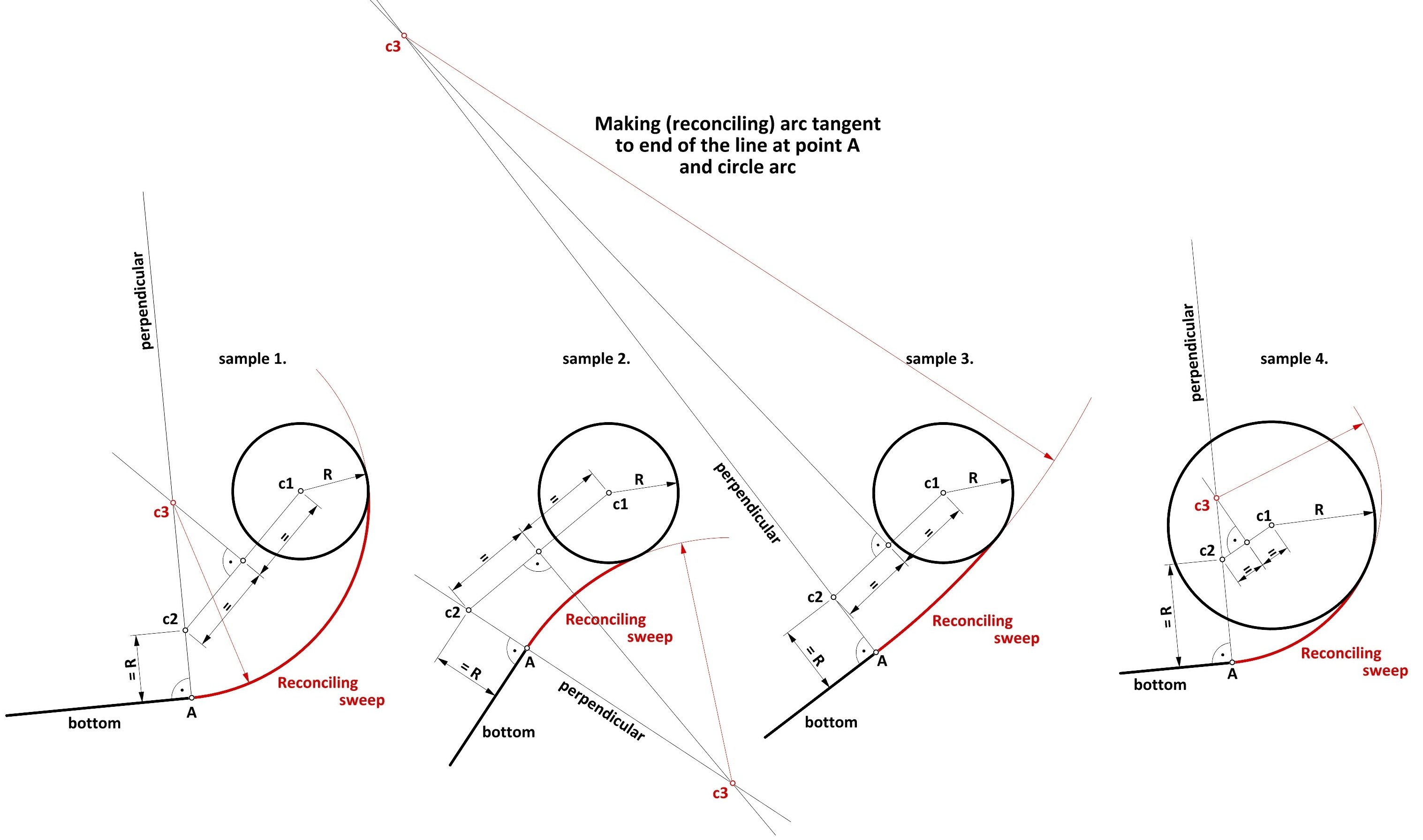
It occurred to me later that one could still show a geometrically rigorous way of determining the reconciling sweep tangent at both ends (that is, to bottom line on one side and to lower breadth sweep on the other). Although the method is extremely simple, it is highly doubtful that it has been used in practice, and especially at actual scale on the mould loft, as can be seen particularly well on sample number 3, where the auxiliary lines extend far beyond the contour area of the frame. The method using a flexible instrument, shown previously in the entry #40, is by far the preferred one, not only because it is hassle-free, but also gives excellent results in terms of the precision of the contours obtained, and this is true even allowing for the minor inaccuracies of handling such a flexible instrument. Be that as it may, below is a method employing formal geometry: 1. make a perpendicular to the line of the bottom at point A, 2. mark point c2 on this line at a distance R from point A, 3. connect points c1 and c2 with a line, 4. find the midpoint of the line c1–c2 and make a perpendicular at this point to line c1–c2, 5. the intersection of the two perpendicular lines (described in steps 1. and 4.) yields point c3, which is the centre of the reconciling sweep.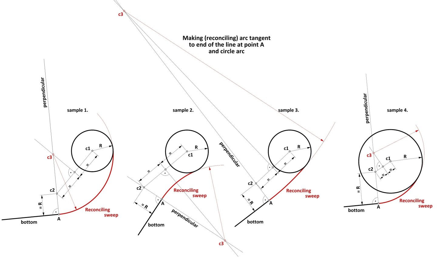
-
The fact that the joinery is anything but sloppy (or perhaps better: irregular) does not mean that the design itself was also careless. Let's take, for example, the buildings of the Incas, the pyramids of the Egyptians or Neolithic Stonehenge. Despite the considerable irregularity of the stone components used, astronomers still find remarkable precision in the assembly of these structures. The same is also perfectly true today — aesthetic aspects aside, it actually does not matter whether the floor in flats and offices is made of boards or tiles of varying dimensions, as long as it is level and sufficiently even. So why waste a good material? The oldest shipbuilding manuals very rarely mention the width of the planks, if at all, as opposed to their thickness and sometimes the minimum length required for more "strategic" components of the structure.
-
Waldemar reacted to a post in a topic:
USS Randolph 1776
-
Well, fine, now that it's “all” cleared up, I at least have a smooth excuse not to spend a perverse amount of money on the decent quality copies of source material needed to prepare free presentations after all. I'm off back to my favourite 16th and 17th century (and European archives ).
-
Waldemar reacted to a post in a topic:
USS Randolph 1776
-
Ah, you may have spoiled my surprise, but perhaps that's for the better, as the further fate of this very venture is quite unclear indeed. On the one hand, you might have had it easier, as we have discussed the issue privately before, yet, on the other hand, with your watchful eye for shapes you yourself must also have noticed the striking resemblance to French light craft of Louis XIV's time, such as the frigate l'Aurore 1697 (body plan shown in the thread on the Mary Rose 1511). Now, I would still like to say that people, while attempting similar analyses, usually focus on comparing dimensions, which is completely missing the point. After all, absolute dimensions, just like many of the proportions, are simply determined by a kind of circumstances which have little in common or being quite independent of design methods, as you pointed out above.
-
Waldemar reacted to a post in a topic:
USS Randolph 1776
-
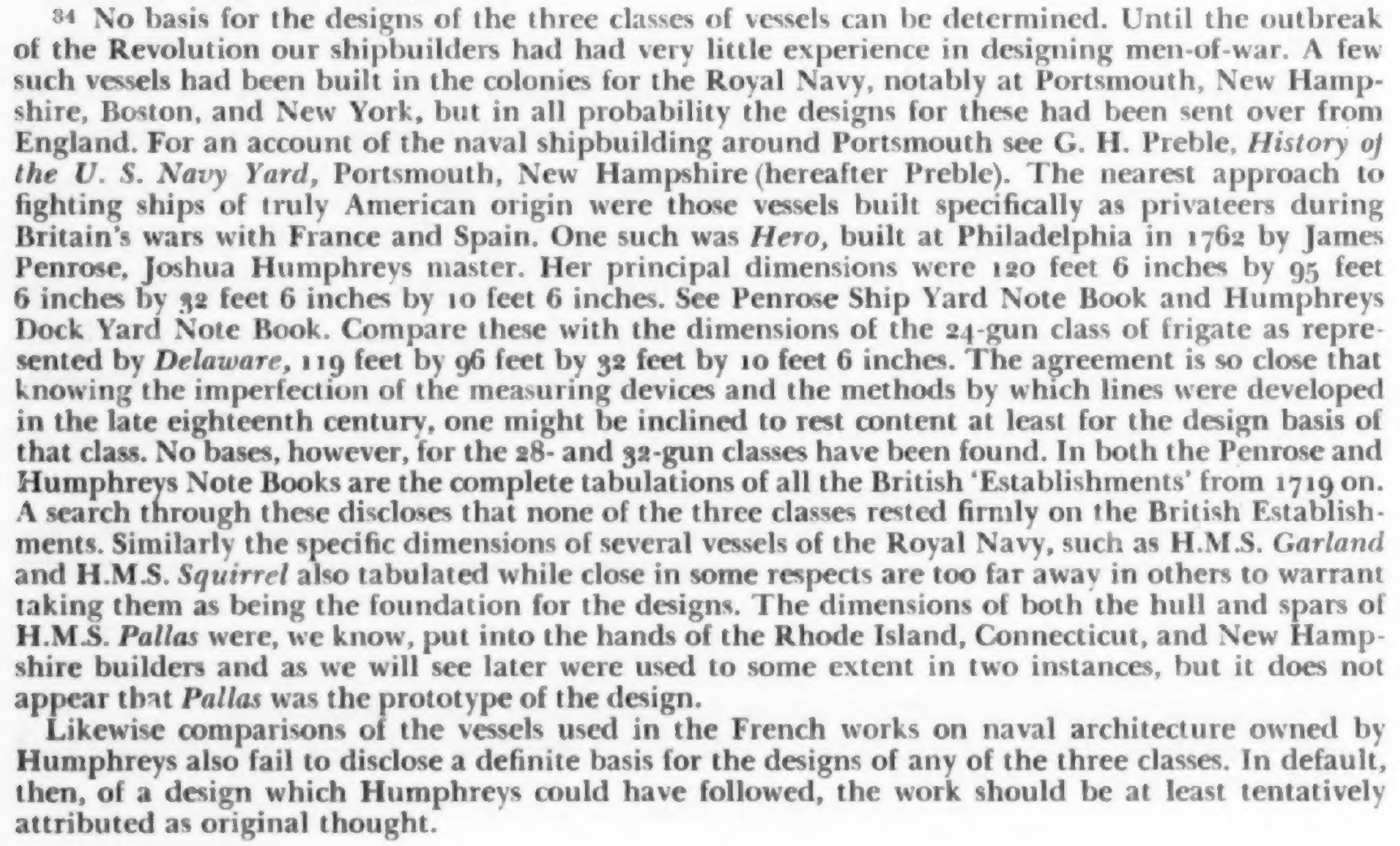
Indeed an excellent article (and easy to find online) — many thanks, Chapman. In a convenient, compact way, it provides information that creates the necessary historical context for this issue. I have also refreshed myself with the content of the related section in The 32-gun Frigate Essex (1799) by Portia Takakjian, published 1990, however, it looks like, that in terms of today's state of knowledge regarding the design methods employed by early American designers, the statement just made by Brewington in his 1948 paper is in fact still relevant:

-
The document is available online for anyone interested (see link below), just only up to page 162 of the manuscript. In a malicious twist of fate, the page with the data for Randolph 1776 is already on the next, first page of the non-accessible part of the whole document, that is 163–164. And the archive wishes USD 37.50 for making one scan of this double page available. Funny. Historical Society of Pennsylvania: DAMS : Volume/Folder : Principal Dimensions [1719-1828] [10581] Under the circumstances, I won't even bother to approach the other archive (the navy) for a better copy of the original ship's plan anymore, and I think I'll give up on this project altogether. It's a pity, because the results and conclusions of this investigation could be really interesting, and actually unknown or unrealized until now. More precisely, I already have near certainty about the design methods applied in early American ships, nevertheless, adequate input material is obviously needed to present this adequately.
-
 Waldemar reacted to a post in a topic:
rigging of the Santìsima Trinidad
Waldemar reacted to a post in a topic:
rigging of the Santìsima Trinidad
-
Thank you, Tony. Yes, I have this publication in my home library, as well as probably all of Chapelle's other major works. Indeed, there is a wealth of interesting, important and useful information about this frigate (actually the whole frigate series) contained therein. Nevertheless, I intend to do something that even Chapelle himself did not do, which is to reverse-engineer the design of the Randolph, and to do this I need a copy of the original design in the best possible quality, as opposed to later redrawings which necessarily distort the original somewhat and, worse, somehow lose very important details found on the originals. By the same token, British-made plans of these early American ships are also unsuitable for my purposes. The point is that I have some observations about the presumed design method used (in a conceptual sense) and I would like to take a closer look at this for confirmation (or otherwise) of these presumptions. They may explain why the American designs were marked by such a specificity of shape rather than another.
-
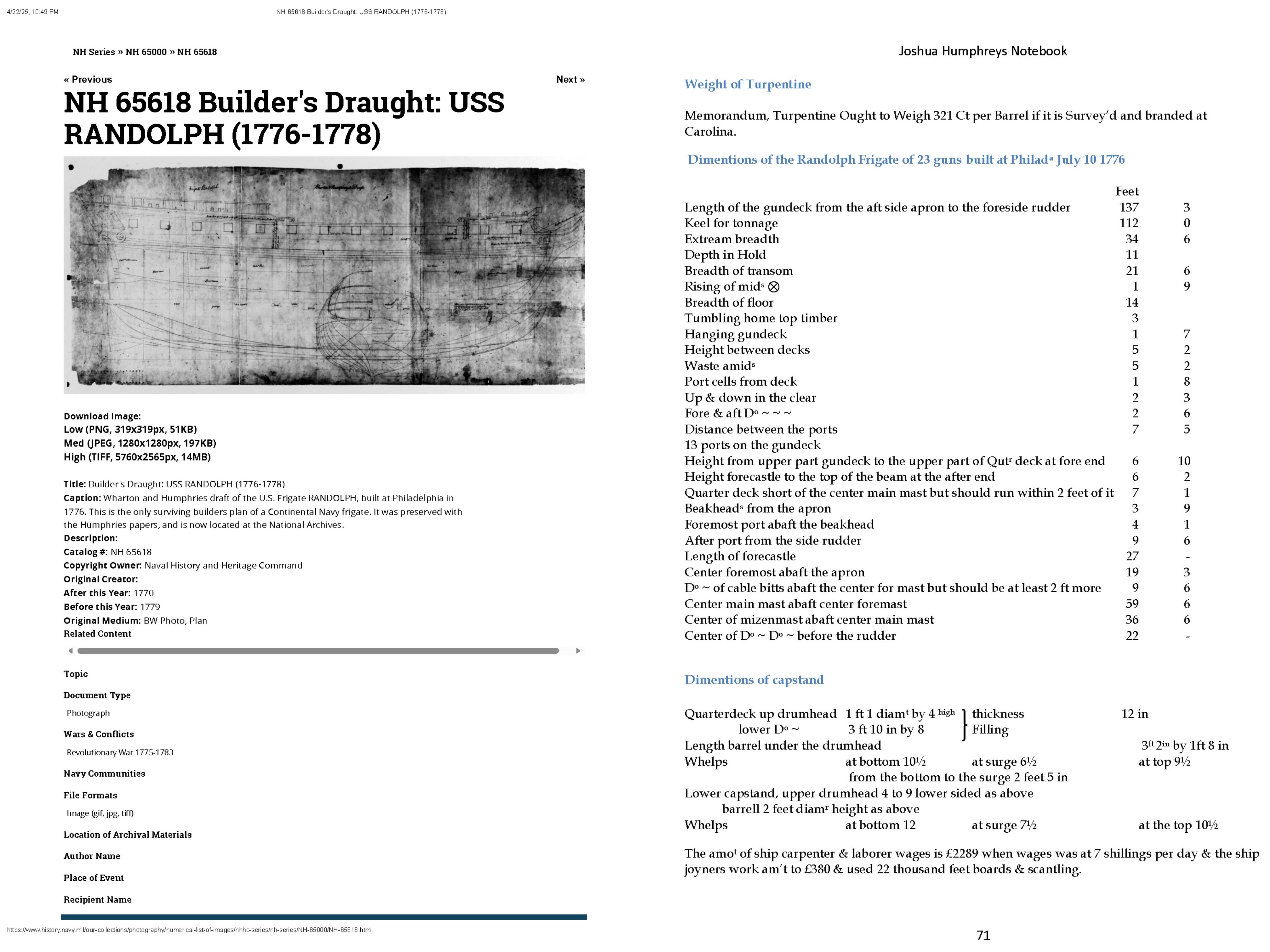
Thanks, Wayne. Nonetheless, I'm already having some doubts as I've noticed in several places in the document that ‘foremast’ has been reworded to ‘foremost’ (and the other way round) and in addition, for Randolph itself, the distance between decks seems to not match the draught (5‘ 2" versus 5‘ 7"). And, almost forgot, the Randolph is listed in the title as a 23-gun frigate instead of 32-gun one.
-
This is most probably the only US ship (frigate) from the Revolutionary period for which original plans have survived. Admittedly, they are available online, but the quality is not the best, as it appears to be essentially a scan of aged microfilm of not very good sharpness, so a lot of the detail is blurred. Does anyone have a better copy than the one available on the archive website? In addition, does anyone have and can provide a good quality scan of a page from the Joshua Humphreys' notebook concerning this very frigate? Granted, this page is already transcribed and available (as is the entire manuscript), but I would nevertheless like to verify the numerical data, which is quite easy to get wrong in the process. Besides, what does the term ‘hanging gundeck’ mean? The stated value on the transcribed page is 1 foot 7 inches. The copy of the draught itself available at: https://www.history.navy.mil/our-collections/photography/numerical-list-of-images/nhhc-series/nh-series/NH-65000/NH-65618.html And reproductions of both mentioned above items:

-
Waldemar reacted to a post in a topic:
Mary Rose 1511 — the epitome of the Northern tradition
-
Mary Rose 1511 — the epitome of the Northern tradition
Waldemar replied to Waldemar's topic in Nautical/Naval History
Thank you also for that last entry, Trevor. Some interesting, previously unknown details, giving useful context and enriching the overall picture. As for your reservations about your text, well, that's my personal experience too, as well as probably that of many authors in the world. I've even accumulated quite a few things that I myself would like to improve on in my past publications, be it paper or on-line, nonetheless one usually doesn't go back to it anymore, just creates new things... There is simply no such thing as absolute perfection and this has to be taken into account. But that's still not at all bad, like completely abandoning further attempts or research. I'm also glad to hear that you've remained a fan of the field despite the different paths your career has taken . -
Waldemar reacted to a post in a topic:
Mary Rose 1511 — the epitome of the Northern tradition
-
Mary Rose 1511 — the epitome of the Northern tradition
Waldemar replied to Waldemar's topic in Nautical/Naval History
Oh, also a mention that I am familiar with one of your publication, indeed already decades old, yet still relevant and I actually use it as well. Attached below for convenient access for possible readers. Trevor Kenchington, The Structures of English Wooden Ships: William Sutherland's Ship, circa 1710, 1993: Kenchington Trevor - The Structures of English Wooden Ships - William Sutherland's Ship, circa 1710 - 1993.pdf -
Mary Rose 1511 — the epitome of the Northern tradition
Waldemar replied to Waldemar's topic in Nautical/Naval History
I'll say frankly that I enjoyed the spirit of that post, especially the observation (if I understood it correctly) that for effective puzzle solving in this particular field, even the closest interdisciplinary cooperation, which can work so well in most other fields, may not be enough. The way I see it in practice is that, to oversimplify somewhat, historians usually have no idea about engineering, engineers usually have no idea about history (including the history of shipbuilding), on top of that one still has to know several languages (written period sources!), geometry, know CAD software for the necessarily personally conducted tests, be critical, persistent and enthusiastic, and so on. Ideally, it all just should be in the same head, if possible. And well, yes, I have read somewhere that the term "Fragments of Ancient English Shipwrightry" for Baker's manuscript has been in reality coined by Samuel Pepys a couple of decades later . Indeed, today's translators do particularly badly with Germanic languages for some reason. I don't think I can help much, except that, if necessary, I can sometimes try to describe something in other words, in the hope of a better automatic translation. But that's also one of the main reasons why I generally reduce the volume of text in favour of graphics. -
Mary Rose 1511 — the epitome of the Northern tradition
Waldemar replied to Waldemar's topic in Nautical/Naval History
Nevertheless, I would still like to show a quite fresh paper (a 2023 publication on the very important shipwreck of the Lomellina of 1516), which exemplifies the way in which archaeologists up to now actually evaluate shipwrecks in an attempt to reconstruct their shapes. In the shortest terms, missing conceptual elements, such as the rake of the posts or the rise of the decks, are borrowed from some manuscript of the period that is deemed adequate (which may still be appropriate in itself, albeit under certain conditions), yet further on this attempt is reduced to merely manipulating the cross sections to just get the hull shapes as smooth as possible, and by the modern method of synchronising hull lines, which has little in common with the methods of the era. And nothing more, no effort to deduce the true design method that was actually used by the ship's builders. Personally, I have no objection if someone is satisfied with such archaeological evaluations, however limited in their aims, scope and methods. But by being carried out in such an unambitious manner, they certainly cannot clarify perhaps the most important issues, namely those related to ancient ship design methods. On the other hand, such a state of affairs is also the result of a generally poor level of knowledge in this area, and this, in turn, precisely of the pernicious influence of today's doctrines which, through their misguidedness, have in fact only led to practical impotence or stagnation and a consequent lack of progress in this kind of research. I am thinking in particular of the today's doctrine of shipbuilding by ‘feel’ or by ‘eye’, i.e. with virtually no conception whatsoever (yet so convenient for humanistically profiled scholarship), and the doctrine of the ‘spontaneously or independently born English school of design’ (yet having just been virtually stripped of its alleged ‘evidence’), and this still conceived in a frighteningly orthodox manner. However, just to repeat — if someone is nevertheless satisfied with such a take, there you go. Max Guérout, Beatrice Frabetti, Filipe Castro, Revisiting Lomellina, 1516: The Hull Shape, 2023: Guérout Max, Frabetti Beatrice, Castro Filipe - Revisiting Lomellina, 1516 - The Hull Shape - 2023.pdf -
Oh, and then there's this a kind of very abbreviated variant of the latter work mentioned above in the form of an article in one of the periodicals. Rivera Vaquero Isidro José - Aproximación al sistema de Jorge Juan referido al aparejo de los navíos españoles, 1753 - 2011.pdf