Lecrenb
-
Posts
275 -
Joined
-
Last visited
Content Type
Profiles
Forums
Gallery
Events
Everything posted by Lecrenb
-
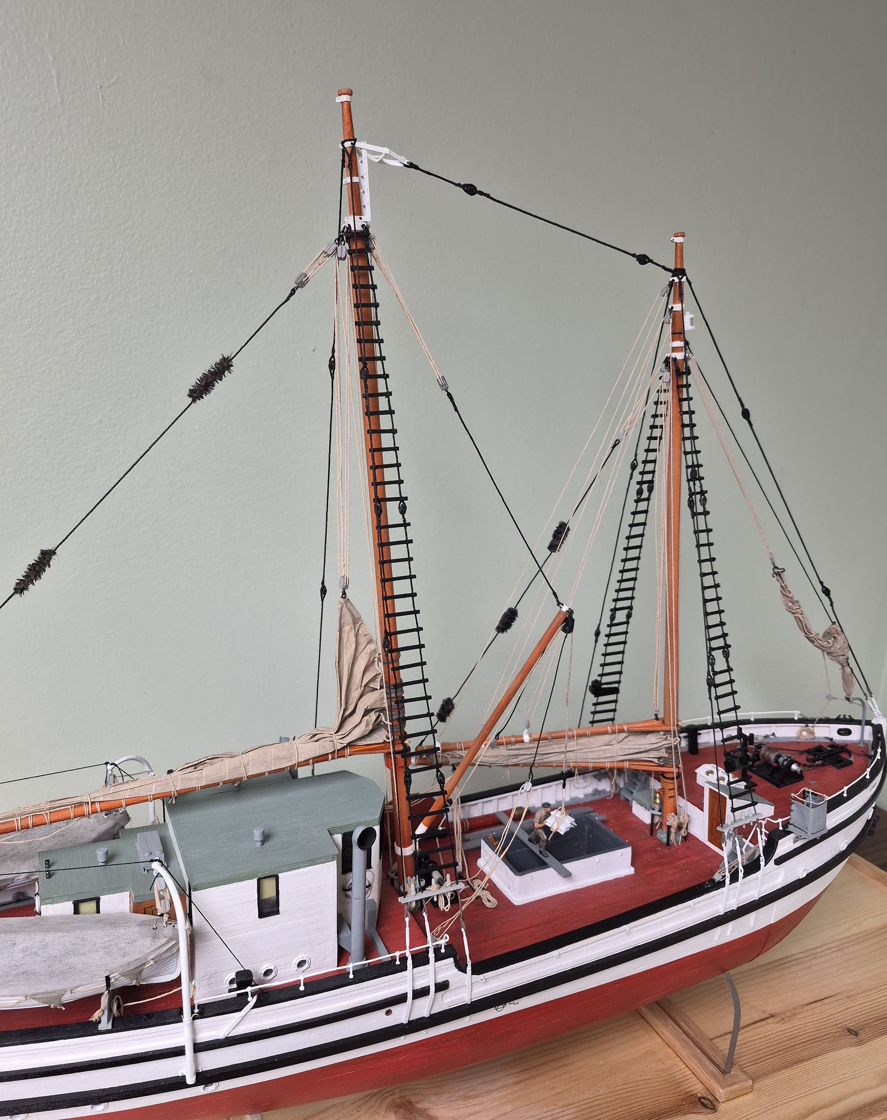
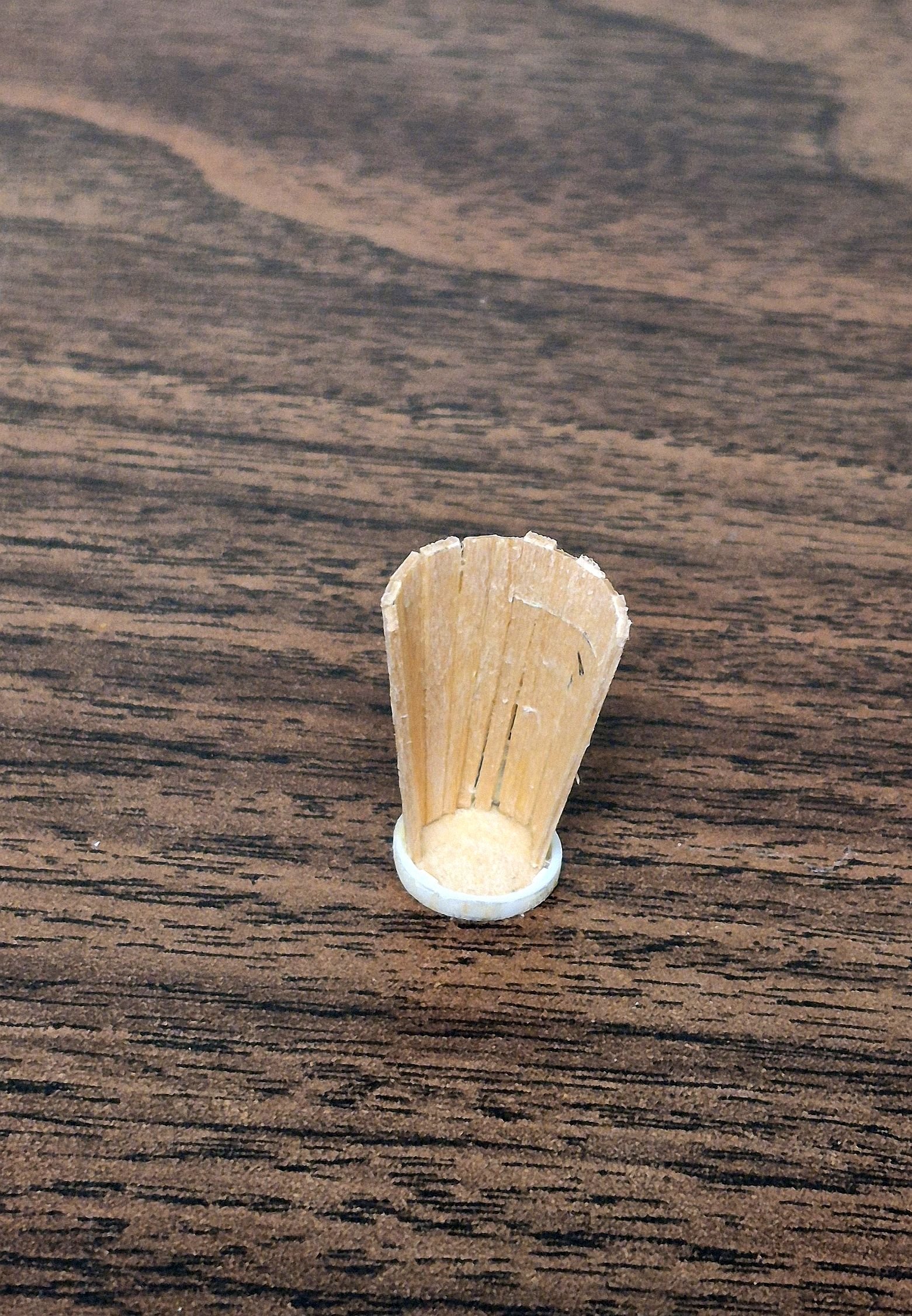
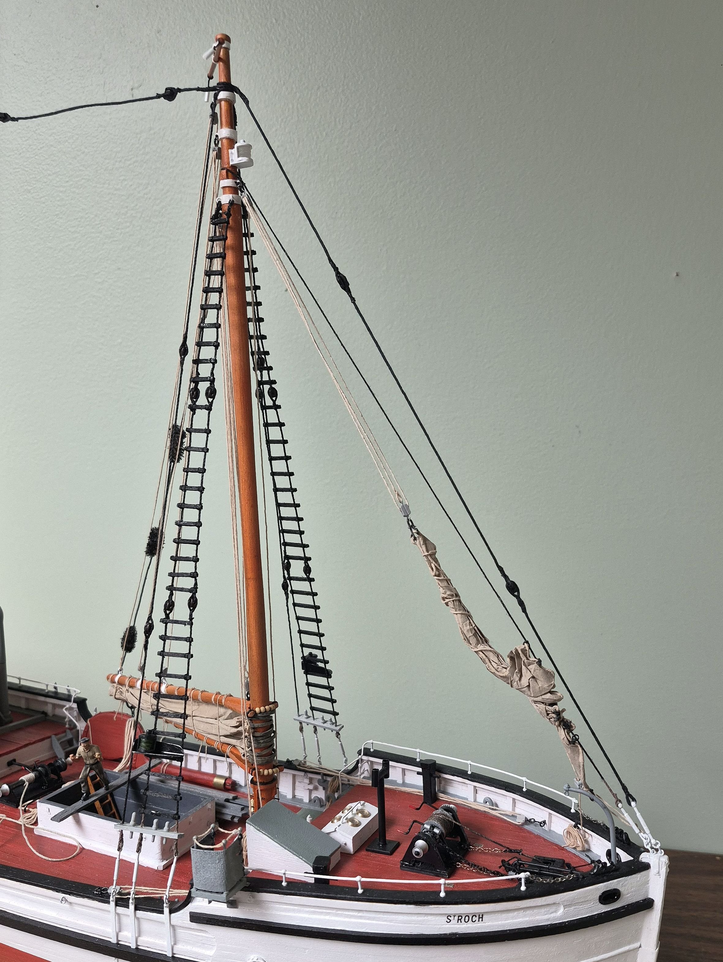
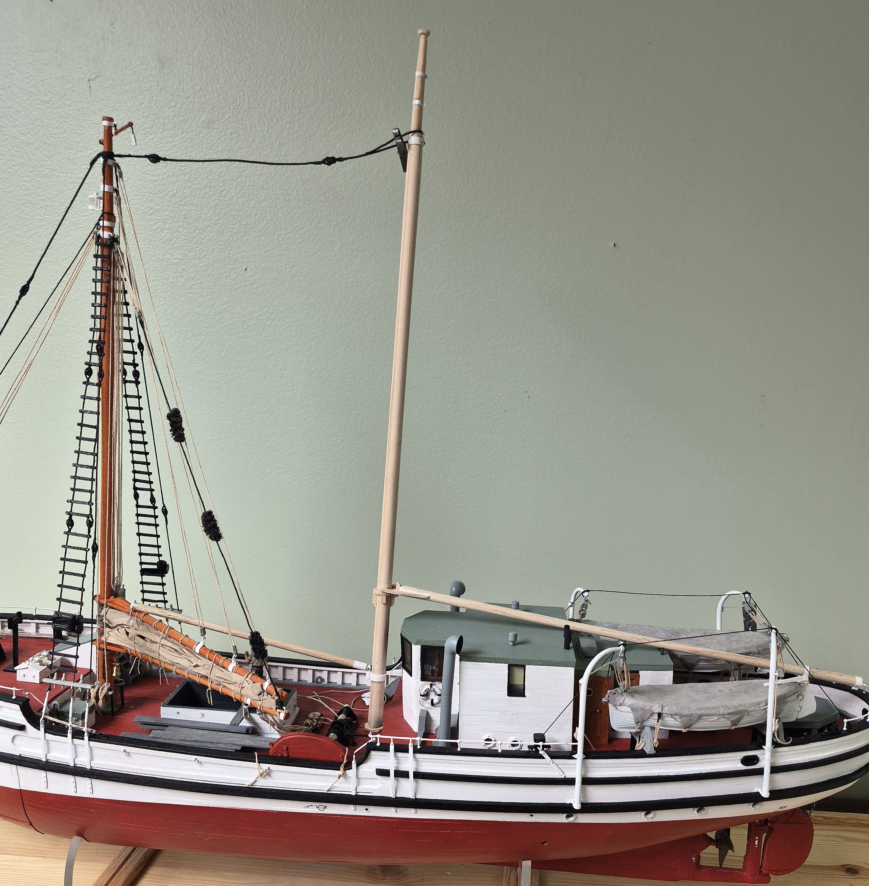
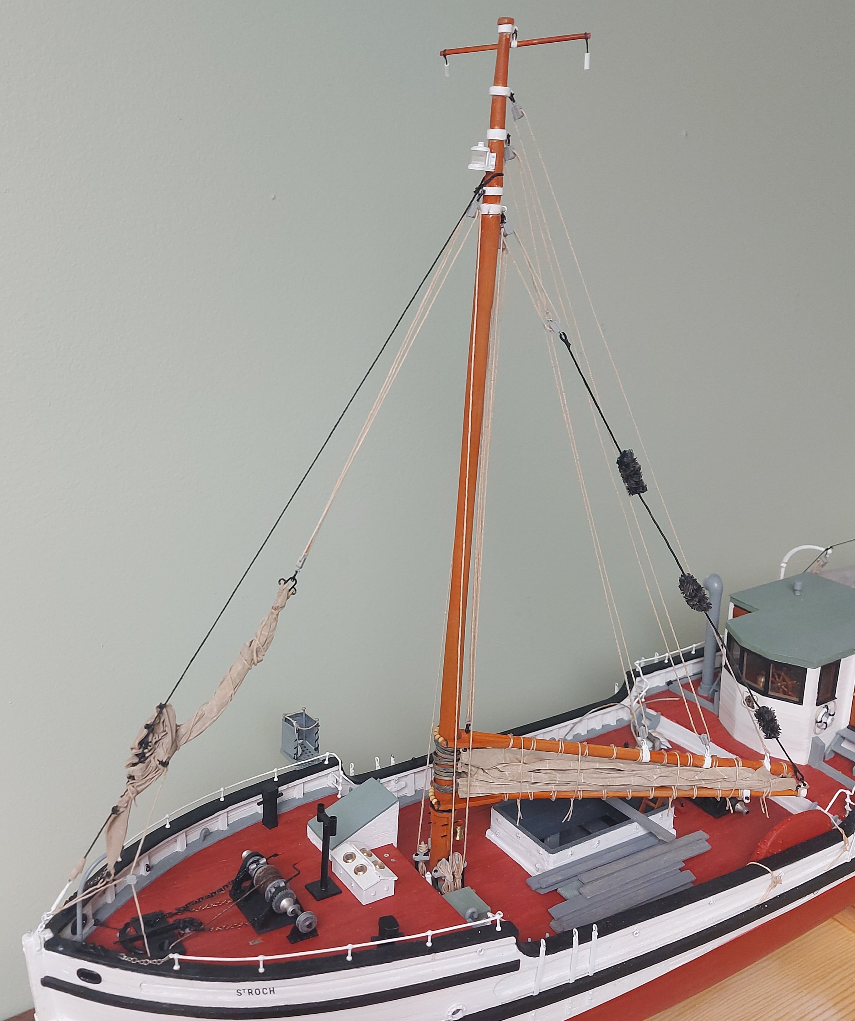
 Thought I would share my weekend's progress... too cold to be doing anything other than modelling! The starboard main shrouds are installed, with the derrick rigging belayed on that side as well... The port side shrouds are being rattled down... in between batches of ratlines I made the first of two cage aerials for the low frequency radios... This is my third attempt, the first two were crap! I took the fore yard off the mast to make things easier. I have also been fussing with the crow's nest, trying to follow the prototype photo. Not perfect but once finished I am hoping for a decent representation! So to finish these goodies off, then on to the preventer stays and the fo'c's'le deck cable reel... Thanks for following along the home stretch! Bruce


-
Thanks Gabe! Thinking good thoughts about the case, probably going with 1/8" glass because of the smaller size and the high cost of acrylic sheets in the hardware stores... Temps are climbing should be around 0 by the weekend! Thanks for all your help! Bruce
-
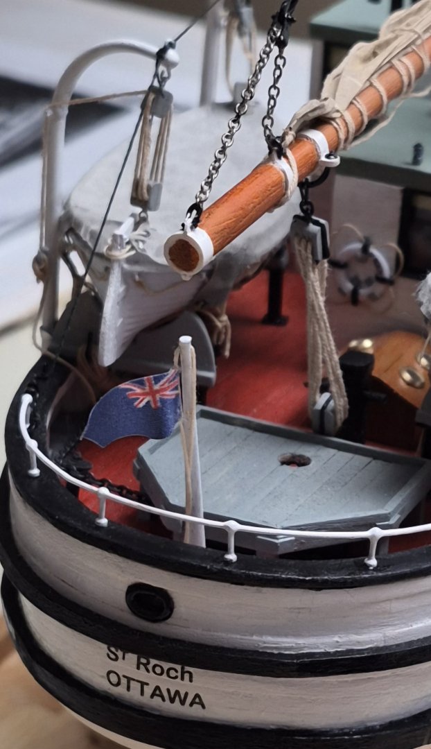
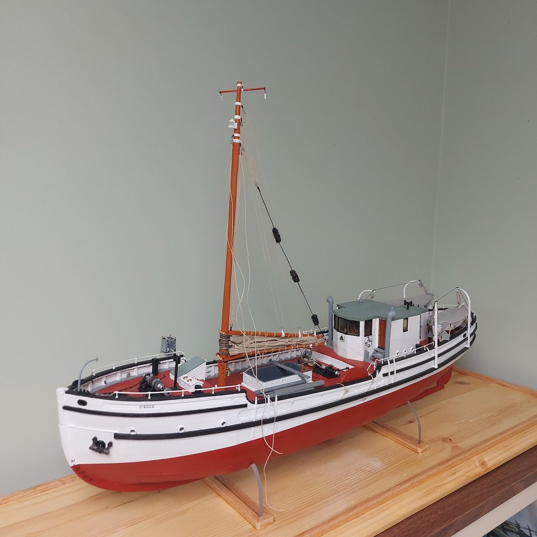
Wrapping up some final details... the ensign and staff are mounted, and the main sheets fitted... The main shrouds are about half "rattled", and I'm thinking good thoughts about the crow's nest... Getting there! Bruce
- 388 replies
-
- 11
-

-
Thank you Phil!
-
Thanks Alan! The help given me by yourself and others really helped the build come together! I am looking forward to presenting my first installment of Lilla Dan's rebuilding in April, also by then St. Roch should be in her case.
-
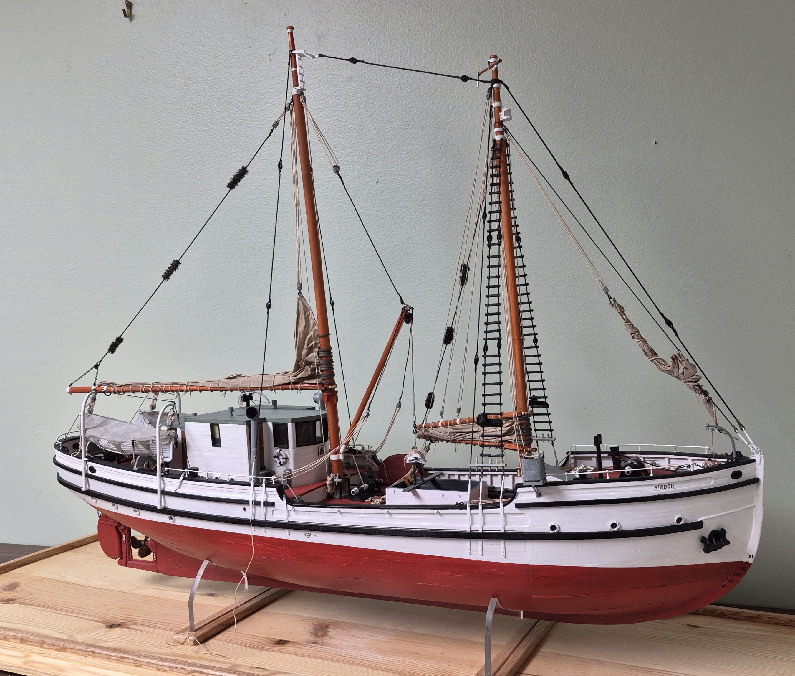
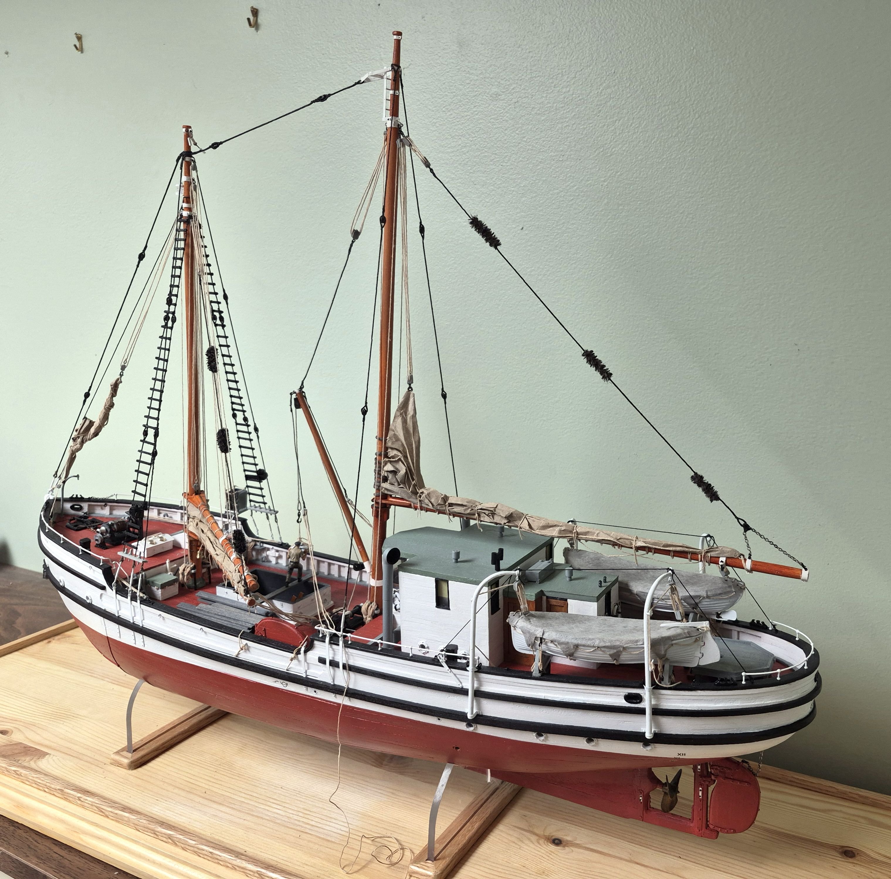
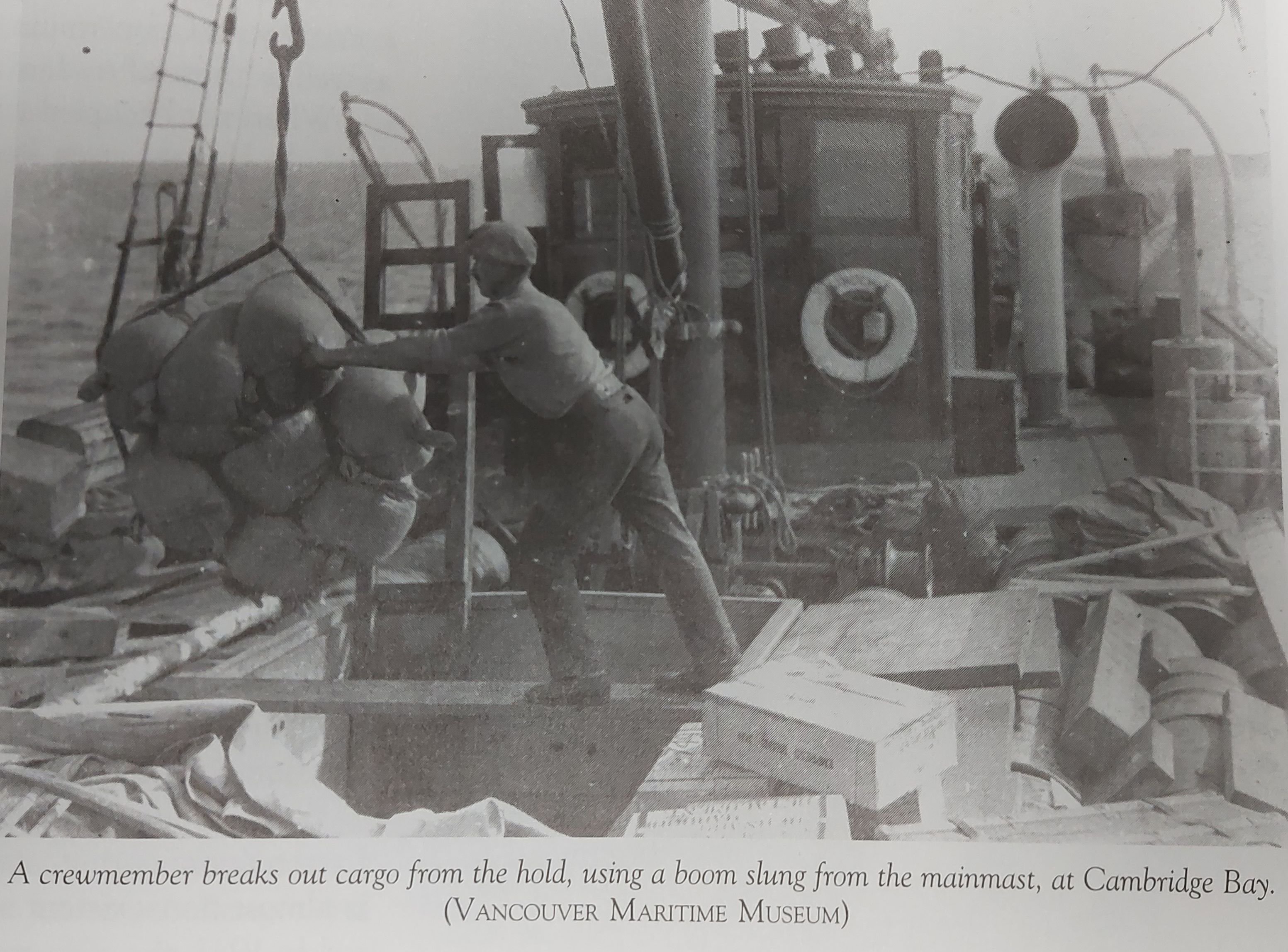
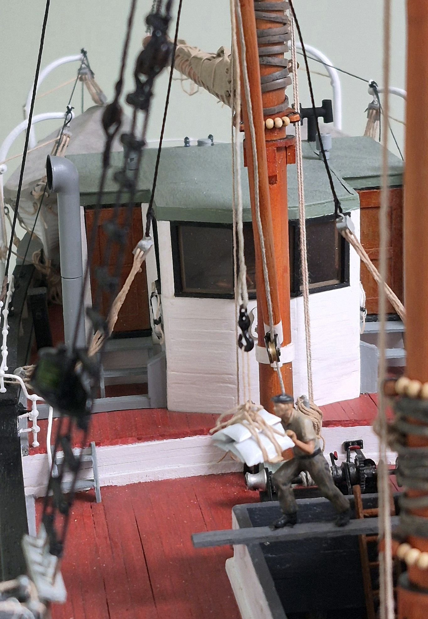
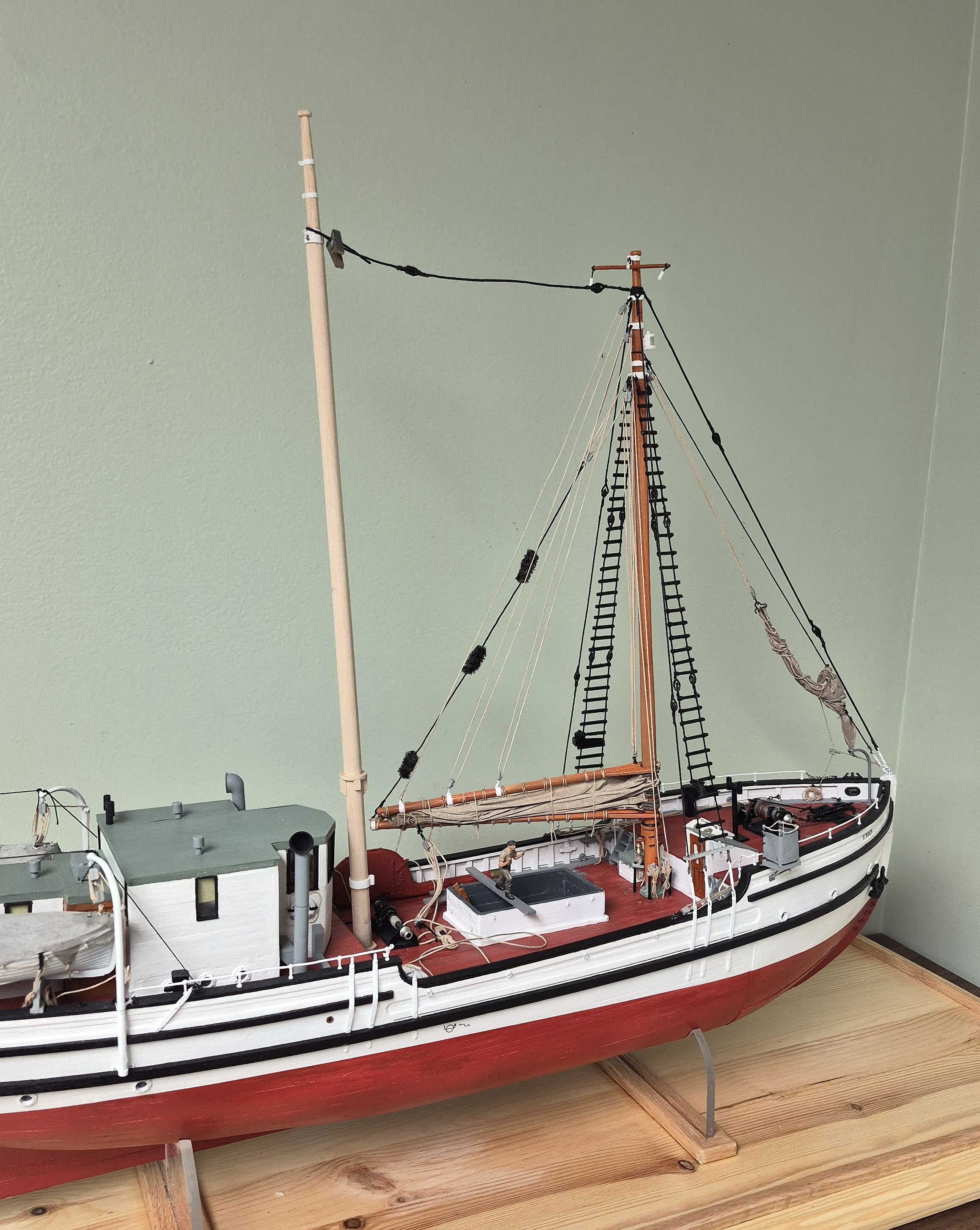
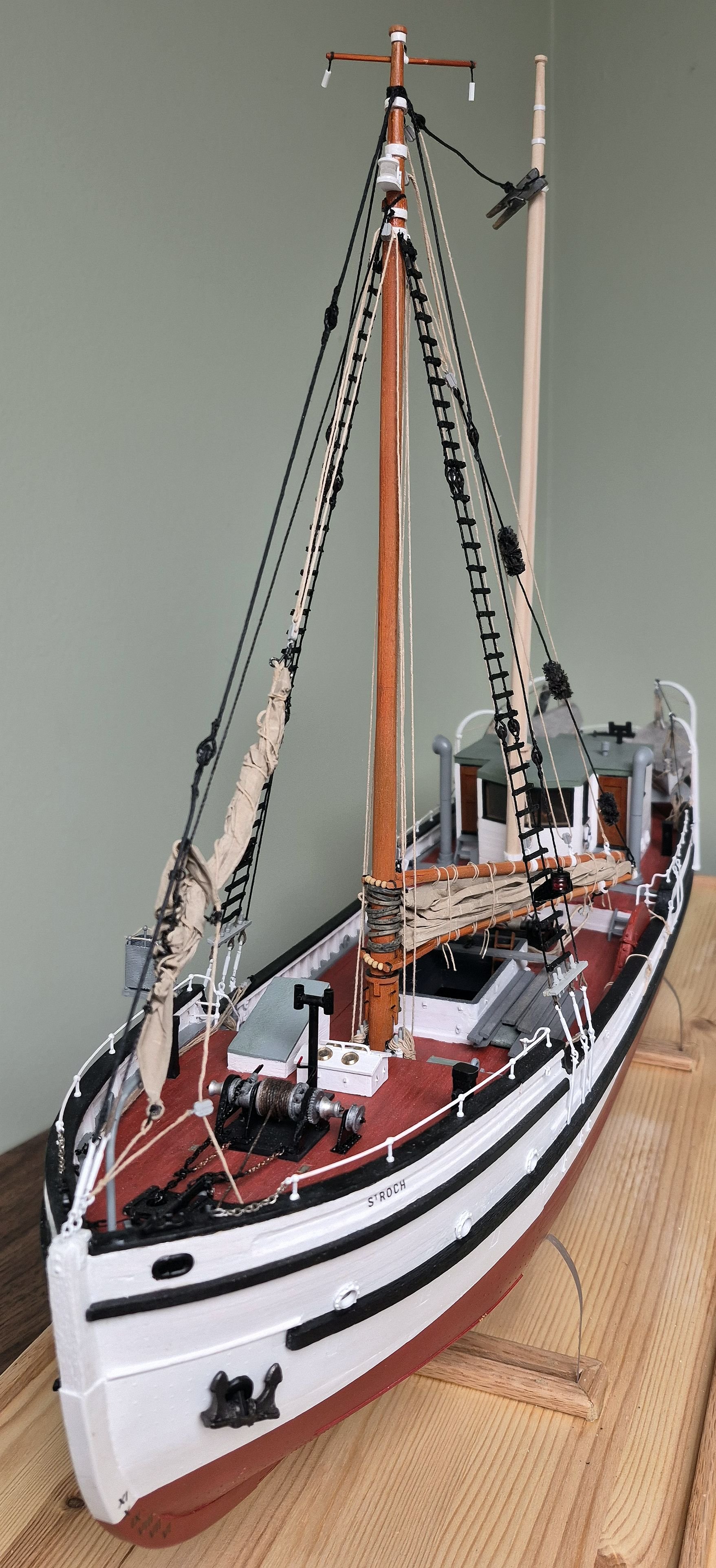
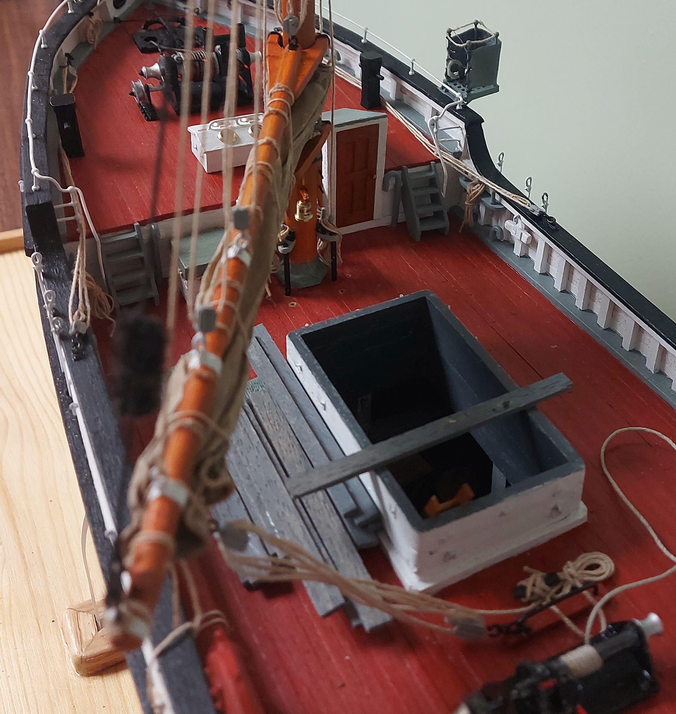
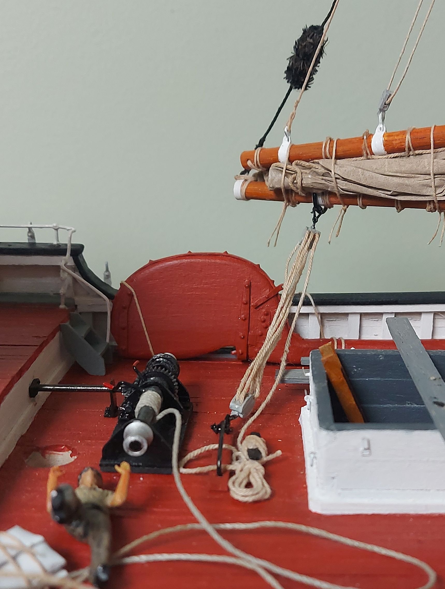
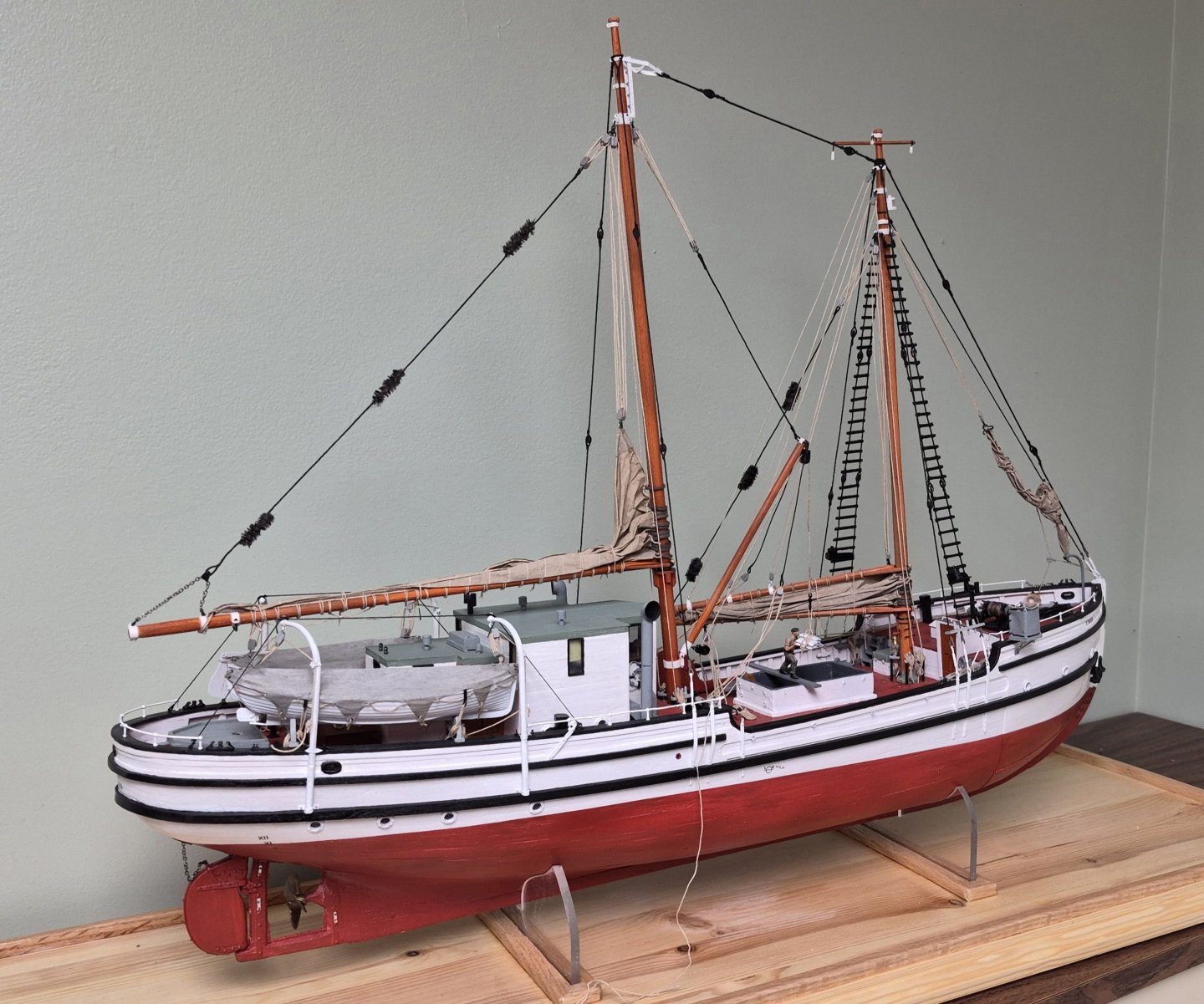
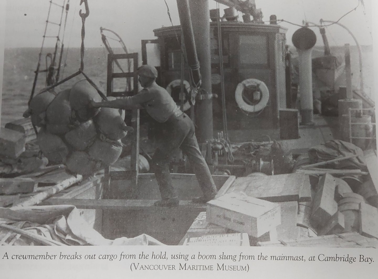
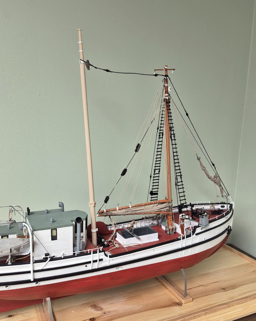
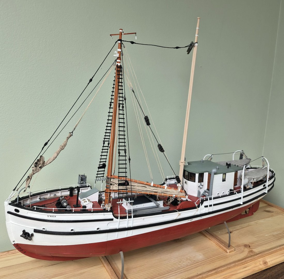
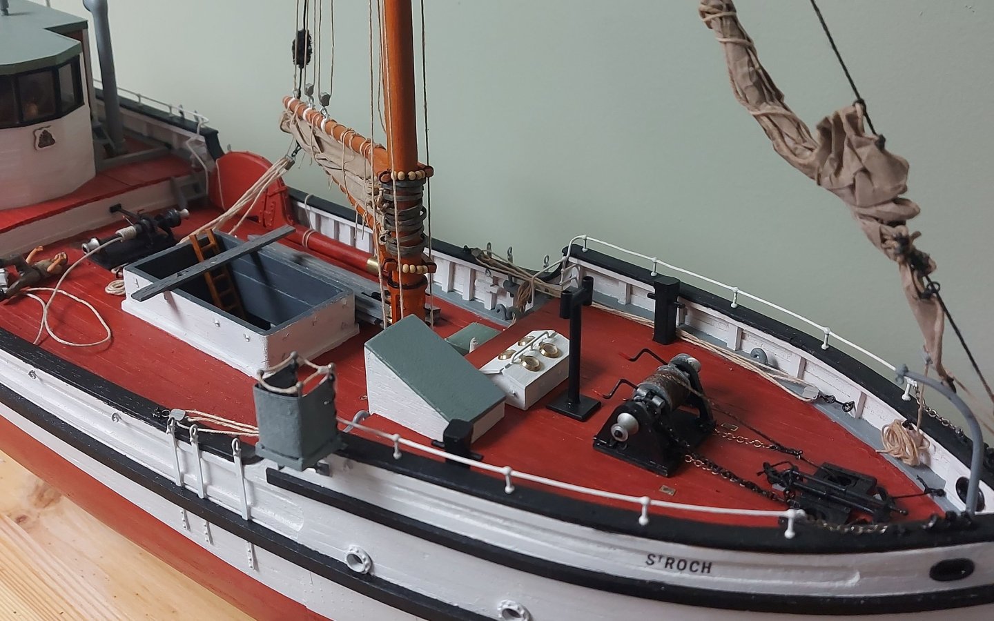
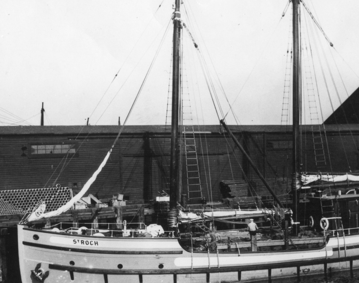
Happy New Year everyone! Now that the relative riots are over, the turkey coma has passed, and the decorations are being put away for another year, it is time to get back to modelling! St. Roch now has her mainmast installed! The steps to finish the spars and main sail, and to assemble the mast, are the same as I carried out for the foremast, so I won't be repeating them here. The first picture is the mast assembled, held in my drill press vise that I brought to my model bench. Note the running rigging is pre-installed, and the cargo derrick is in place with my scratch built gooseneck. Note also the chain and footropes on the main boom... St. Roch originally had a gaff mainsail, but this was cut down and the gaff removed by captain Larsen after her maiden voyage. Presumably the smaller sail area helped her sailing characteristics, which were not very good. And here is the mast installed onto the ship... The running rigging has been belayed to the pins at the mast foot. The back stays are installed. The main stay is installed to the spreader on the mast. The crow's nest will be installed above the spreader, which keeps the stay out of the way of the nest. I made the Jacob's ladder and installed it between the top of the shrouds and the bottom of the nest. As will be seen, crew climbed into the crow's nest through the bottom, not over the top. The shrouds have yet to be made and installed. In these next two pictures you can see the cargo derrick set up, with the crewman pushing his load of sacks to the side of the ship. The tackles used to swing the derrick are left slack on purpose, and the ends will be belayed to pins at the lower end of the main shrouds. I normally do not include crewmen, since I am not very good at making them. However a friend on another forum and his 3d printer came to the rescue. I thought the open hold looked too sterile and the crewman would give scale to the model, so I used the following picture as inspiration to create this mini-diorama. The photo was taken in 1928 during St. Roch's maiden voyage, as evidenced by her original small deckhouse and the note that she is unloading at Cambridge Bay. It is interesting to note that there is no sailor manning the winch, the crewman appears to be working alone to get the cargo over the side and into, presumable, a shore boat... This last picture shows my take on the scene... Now all that remains are the main shrouds and some final details before St. Roch goes into her display case! Thanks everyone for looking in and following along, and for your comments and support during my build! Regards, Bruce


- 388 replies
-
- 19
-

-
-
Well, it has been three weeks since my last update, and I was hoping to have had the foremast completed before now... but the empty calendar filled up with commitments that took a higher priority, and here we are! The running rigging on the foremast had already been completed. As you can see in the first picture below, I have been making stays and shrouds... The ratlines are iron bars, I used balsa wood, because when it is tied to the shroud the thread takes a small bite into the balsa and holds the ratline where I want it. The next three pictures are different views from around the ship... The main stay and main mast are posed... the stay had to go on now since the forestay is over top of it. It does not belay to the main mast, but to a spreader that will be under the crow's nest. The sailor has gotten over his hangover and fall into the hold, and is back on his plank awaiting the cargo derrick. The running lights were modified the same way as the masthead light. I have been able to make some progress on the main mast and spars, which consist of the main sail boom and the cargo derrick. I also have made the main sail... This last picture shows the derrick and boom posed on the main mast. I made the derrick's goose neck from styrene bits and bobs. Most of the bands are installed and then will be ready for the spray booth! If I don't get back to the forum before Wednesday I hope Santa is good to all of you, and my wishes go out to everyone for a Merry Christmas! Regards, Bruce


- 388 replies
-
- 15
-
-
-
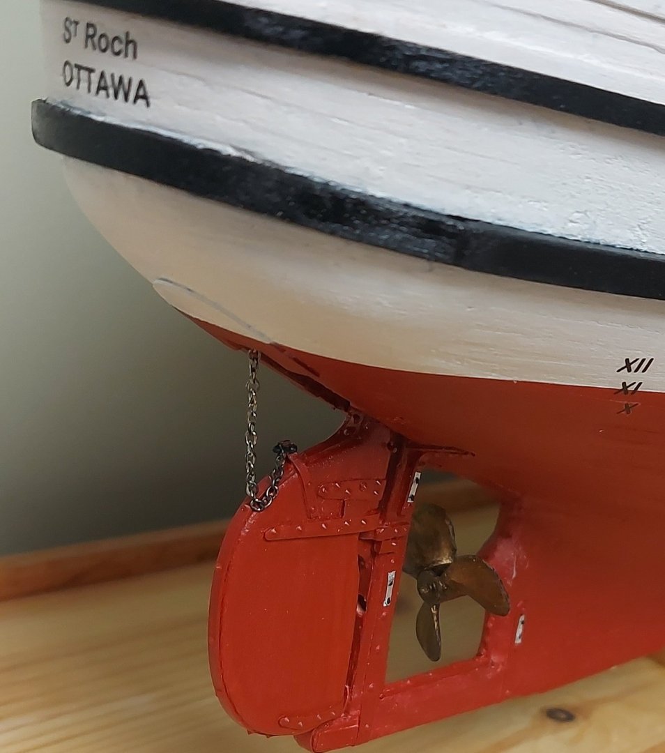
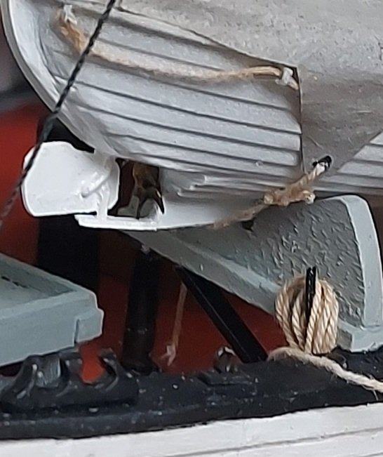
Taking a break from tying shrouds... can't imagine the fun y'all are having rattling down a square rigger like a tea clipper or Victory!! I'm satisfied with the prop colour, so St. Roch now has motive power! And so does her motorboat! This prop just fit... but I didn't want to shave down the blades because they are so delicate, so I hope it is posed convincingly! Regards, Bruce
- 388 replies
-
- 14
-
-
Ha Ha... good question! Because he was posed on the plank athwart the hold, and I knocked him off! Once I get the main mast and derrick on, he will be pushing a load of cargo to the side of the ship. I wasn't going to show this, but I wanted an open hatch, also he gives scale to the model.
-
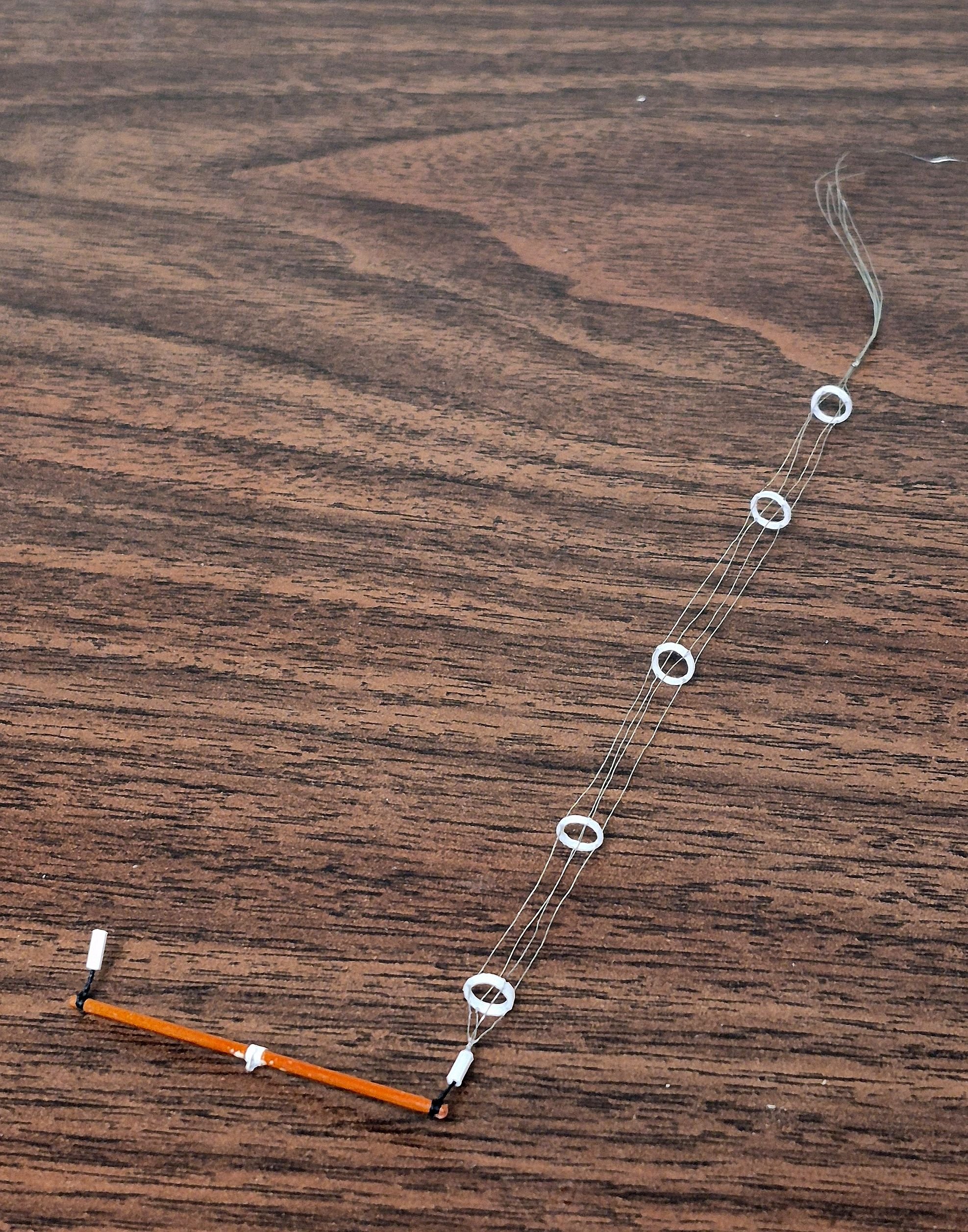
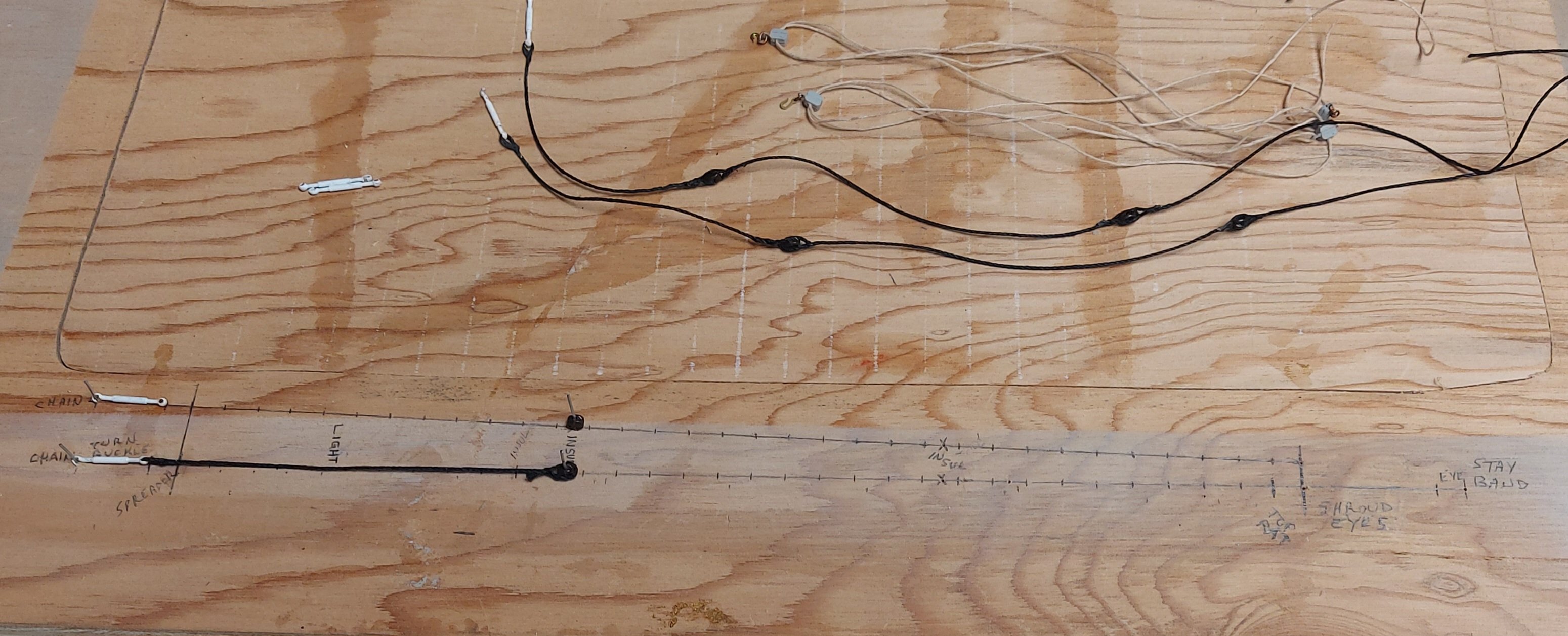
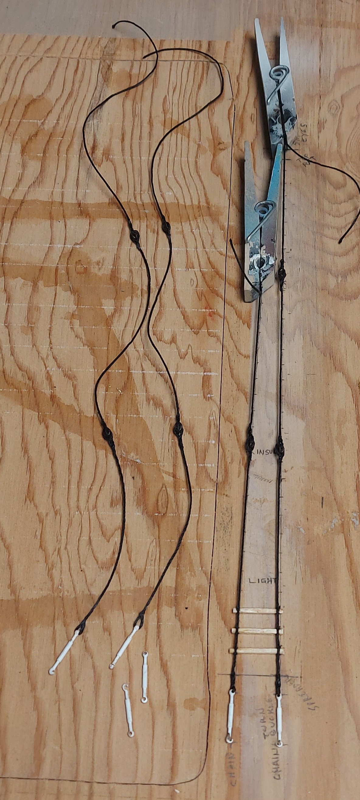
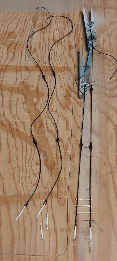
Running rigging at the forward end of St. Roch is now complete, and work continues to prefab the shrouds and stays... The previous picture shows the back stays being built together on a template that I made on my silkspan frame. This picture shows the stays finished and the shrouds started. This is a clearer shot of the template... the jib sheets (ready for paint) are also seen in this picture. The template started out as one line for the back stays, with the insulator locations marked. Holes are drilled for pins to hold the turn buckle, insulators, and at the top eye location. The two stays already made are shown, ready to be installed. Then I added the second line to make the shroud template, moving the insulator and eye locations, and indicating where the ratlines (which are wooden slats) will go. Here is the shroud partially made... Note the running light will also be fastened to the shroud. Once the shrouds are completed I will adjust the top end of the template for the longer stays and shrouds required for the main mast. Thus the template evolves while the lower end turnbuckles remain constant and properly spaced. Moving on, the jib sheets got installed... consultation with my museum contact and sailor friend was required, since photos do not show them rigged to the clew while the sail is furled. Consensus is that they were still rigged on the ship and not stowed away, so they would be handy if the sails needed to be set. I accordingly belayed the ends to the pin rails just aft of the fo'c's'le break, and mounted the blocks to rings on the cap rail as shown on the rigging plan. They may have been mounted lower down, on the staghorns, but there is no consensus for this, so I went with the plan. The horns may have been used to belay the running end of the sheet when in use, again, not sure, but makes sense... I ran the sheets out to a pair of rings near the bow. Whether or not these were installed for this purpose I do not know, but their presence was too convenient to ignore, so the jib sheets were hooked to them. This arrangement keeps the rigging from fouling the deck while being ready to bend onto the sail. Here is the port side jib sheet... The next picture shows the starboard jib sheet, and the foresail sheet as well. This last picture is a clearer shot of the foresail sheet, which was made up on the model after the blocks were prepared and painted. The boom is posed over to port to allow the cargo handling to be shown. I wasn't sure what to do with the extra line, since there was no obvious place for it, so I placed the coil between the cleat and the horse... I could move it if a better option presents itself, we'll see. That's it for now, back to the foremast shrouds... once the standing rigging is on the foremast I will repeat everything done over the last few weeks on the main mast. Regards, Bruce


- 388 replies
-
- 16
-
-
-
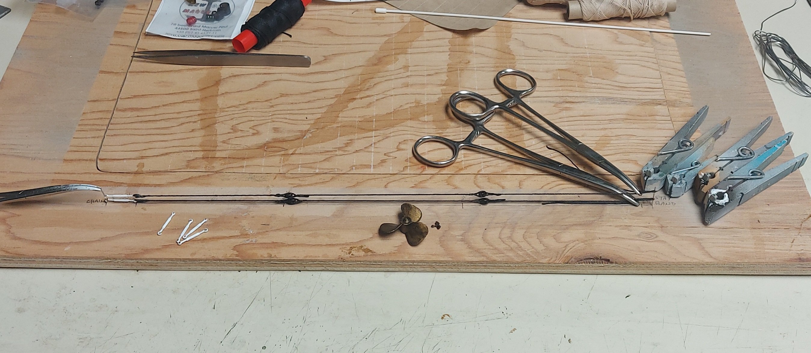
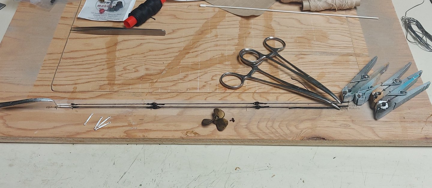
Making foremast rigging continues... While waiting for the paint to dry on the jib sail sheet blocks I completed the bottle screws for the foremast shrouds, and the foremast back stays which are now ready to go onto the model after a bit of line trimming. The insulators on the back stays, and that will be on the rest of the standing rigging, are dark brown single sheave plastic blocks. These were donated by someone who gifted a bunch of goodies to another model club, and they look exactly like porcelain wire line insulators! A while ago I appealed for a very small propeller for St. Roch's motorboat... a member of another model club stepped up and offered to 3D print one for me! Also, since scaling is easy with 3D printing, he cranked out a larger one that I can use as St. Roch's ship's prop, which saved me the time and trouble of making a brass prop like I did for HMCS Chicoutimi!! These parts recently arrived despite Canada Post's best efforts, and the small prop and plastic blocks can be used as-is... the larger prop got some final sanding to shape the blades. Both received a coat of brass paint, then a dry-brushing of semi-gloss black. Going over the paint with a drop of thinner on the brush smoothed out the colours. I am hoping to get a bronze look... if successful then they are also ready to be mounted onto the model. All these parts are shown in the picture... I must say how much I appreciate all the positive feedback I have received so far during my build of St. Roch, and also the fellow modelers who have stepped up with offers of 3D printing and donating parts I couldn't make or find... Thank you so much for improving my model! Bruce
- 388 replies
-
- 12
-
-
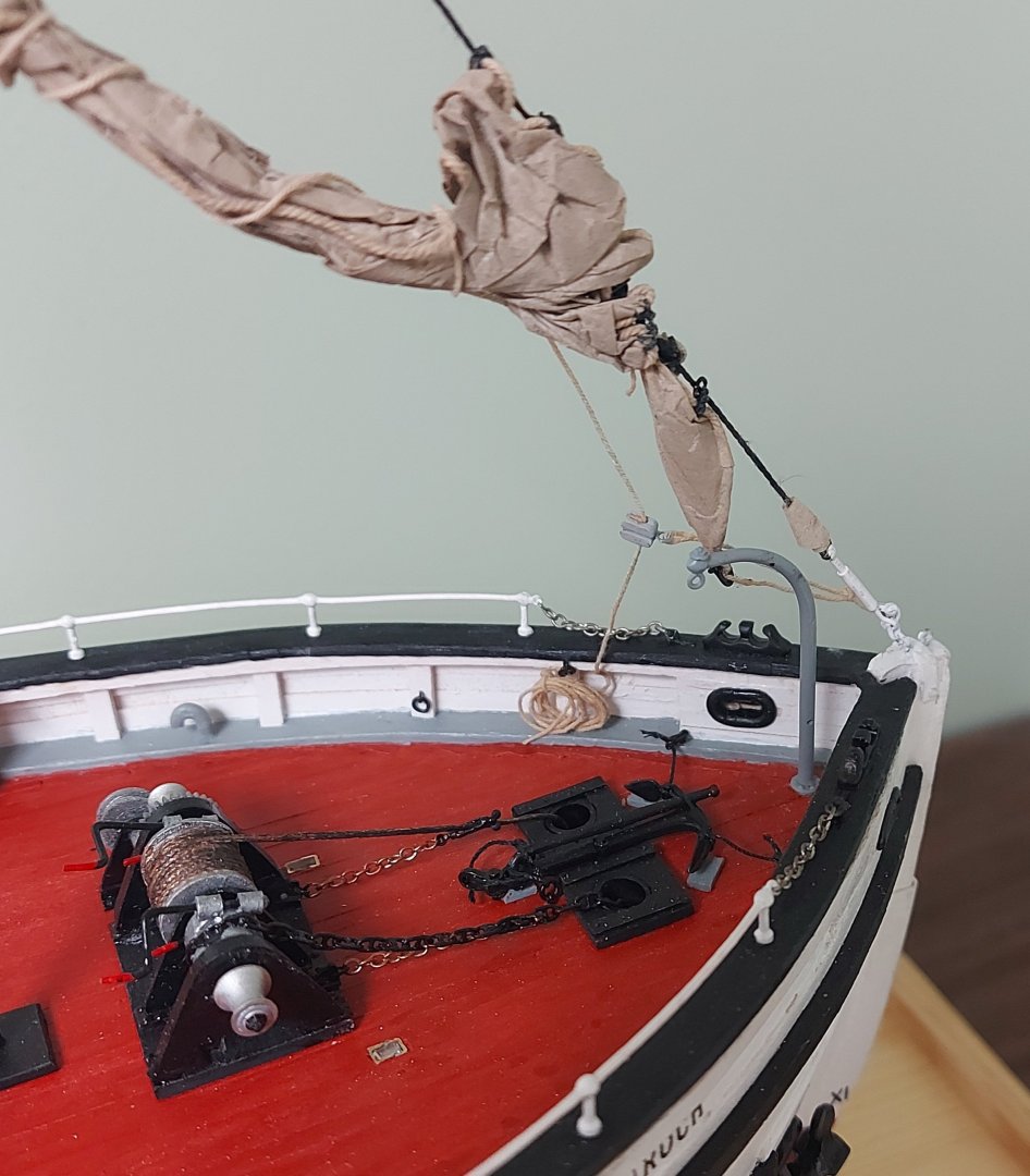
Furling the jib onto the model is now complete! The jib stay went on without an issue, I passed the cable strands through the jib stay to create the eye at the mast, leaving enough slack line to pull the stay taught. Of course the jib was already attached to the stay, so once the glue had set up I only needed to belay the halliard and downhaul, shown in the first picture... Observers who have been following along may very well ask why is the halliard shackled to the clew instead of the head of the jib, and where are the sheets? One of my contacts on the Board of the Vancouver Maritime Museum is also a sailor who lived on board his ship "North Star of Herschel Island", the last of the fully rigged fur trading sailing ships, and a contemporary of St. Roch. He has been a valuable source of details about period rigging. St. Roch was a poor sailor and rarely used her sails, especially to move through the channels in the pack ice. Her jib needed to be triced up in order not to lay across the machinery on her fo'c's'le. I do have one picture showing the jib furled with the halliard at the head and the sheets on the clew, but the sheets do get in the way of the fo'c's'le deck access, and all other pictures show the sail furled without the sheets. He and I agreed, based on the photographic evidence, that the halliard was removed from the head of the jib and shackled to the clew in order to furl it out of the way. This next picture shows St Roch in 1928 with the sail furled in this manner, all other later photos show the jib hauled further up the stay as I have modelled it, but this is the clearest picture of the rig. This method does allow the sail to be set quickly if needed, and the next picture shows the downhaul, which is shackled to the head of the jib, as I have belayed it to a ring on the bulwark. The rigging plan shows the downhaul, but not where it belays. If it was taken to the foremast like the rest of the rigging it would foul the windlass and other fixtures on the fo'c's'le. Since the downhaul was rarely used and only under tension when pulling down the jib, my consultant and I agreed that coiling it onto a bulwark ring would be correct, keeping the line handy while out of the way. So what of the sheets? I showed a previous picture where today they are coiled on top of the companionway roof, but this is obviously incorrect for St. Roch during her working life, and if they were shackled to the jib's furled clew they would be in the way of the fo'c's'le deck... More discussions with the Museum, and the answer we came up with shall be revealed shortly! Stay tuned, Bruce

- 388 replies
-
- 12
-
-
Thanks Alan!
-
Glad you're enjoying following along! The research never stops, I just figured out something interesting about mounting the jib, which I hope to share shortly! Regards, Bruce
-
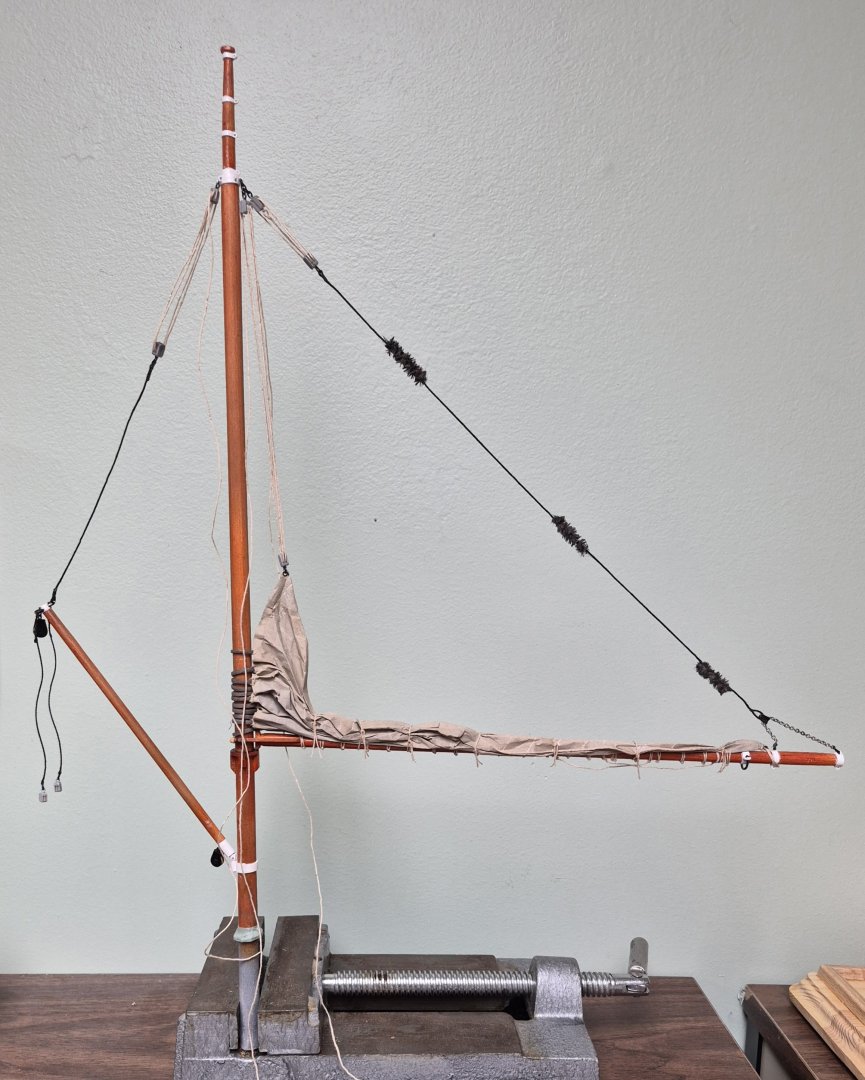
Moving right along, the first photo shows the pinrails at the base of the foremast with the rigging tied off... Next I added the rings to the jib, completing that sail... After which I reeved the jib stay and added the bottle screw and block at the foot of the sail... The chain at the end of the bottle screw attaches to an eye on the stem of the ship, while the jib stay ends in an eye near the top of the foremast. The block is for the downhaul line. Note the iron cringle at the clew, this is for the pair of jib sheets. The next picture is the jib clew on St. Roch. That line is not a sheet, it just spreads the sail for public viewing. The actual sheets are the rope coils on top of the companionway roof, if they were rigged they would interfere with public access to the fo'c's'le deck. This last picture is the jib furled on the bench... I think it looks pretty much like the bundles I see in photos. and it should hang realistically once the stay is fitted to the ship (fingers crossed). I shackled the downhaul line to the head of the sail. Most photos show the jib triced up to the foremast by the clew, and that is how I will mount mine to the model. That comes up next (I hope)! Regards, Bruce


-
Thanks Phil! Yes, I am happy to reach this milestone but with St. Roch it means 'rinse and repeat' because I have to repeat everything on the mainmast now!
-
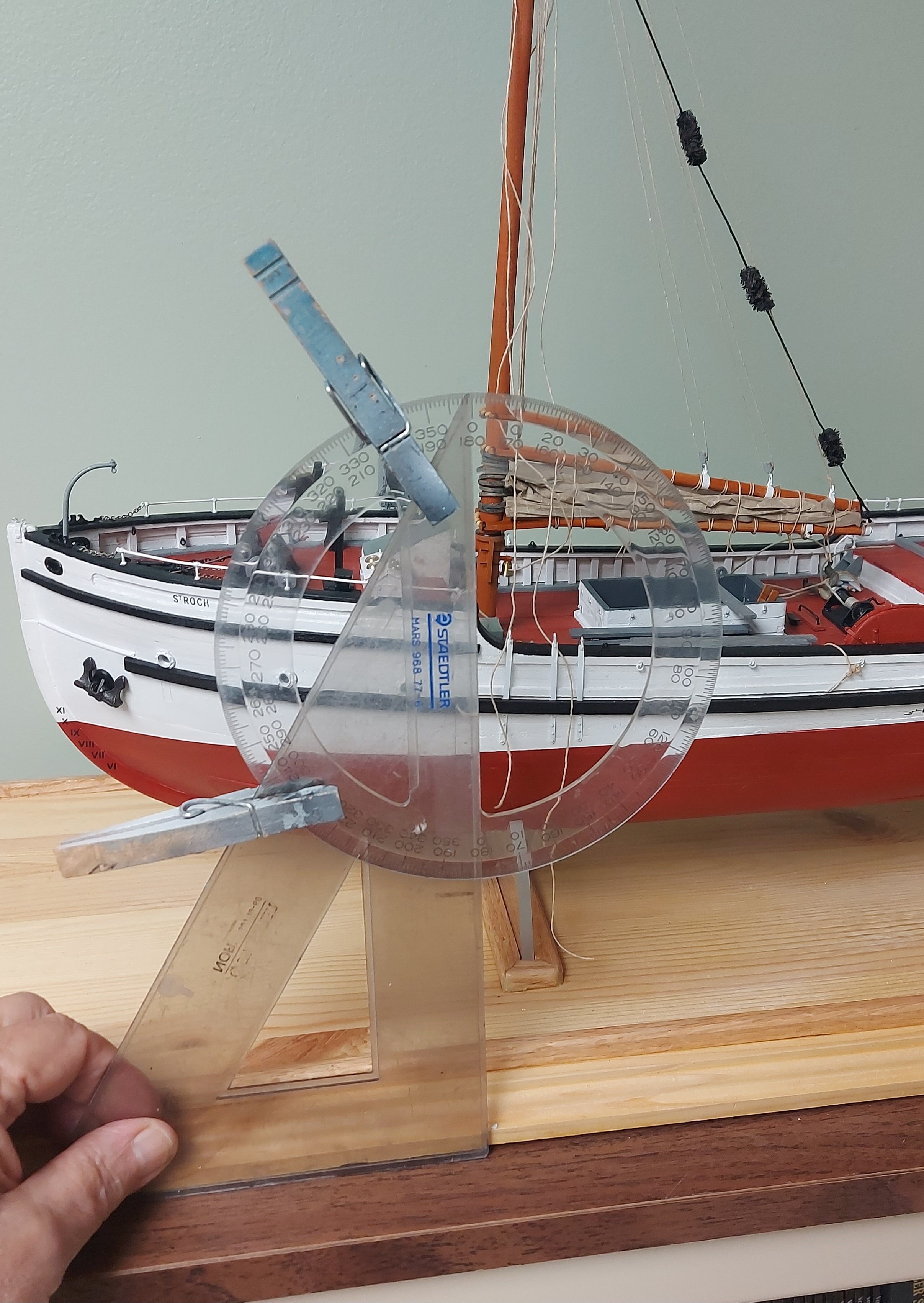
Well, it finally happened... the boom lift got rigged and the mast got set into the hull permanently... I checked the side to side positioning against the line of the stem and the center of the wheelhouse, and in the next picture I am checking the 3 degree rake angle after confirming the ship is set properly onto her base... After the glue has cured overnight I will add the pin rails to the bottom of the mast and finish up the running rigging. I'm in the process now of making bottle screws for the standing rigging, furling the jib, and making my shroud template. Lots of fun! Regards, Bruce

- 388 replies
-
- 13
-
-
-
Thanks Phil... I agree and think the yarn version might be better in smaller scales. Later I'll rig up the lift and think good thoughts about mounting the mast permanently. Bruce