HOLIDAY DONATION DRIVE - SUPPORT MSW - DO YOUR PART TO KEEP THIS GREAT FORUM GOING! (Only 20 donations so far - C'mon guys!)
×


Lecrenb
-
Posts
262 -
Joined
-
Last visited
Content Type
Profiles
Forums
Gallery
Events
Everything posted by Lecrenb
-
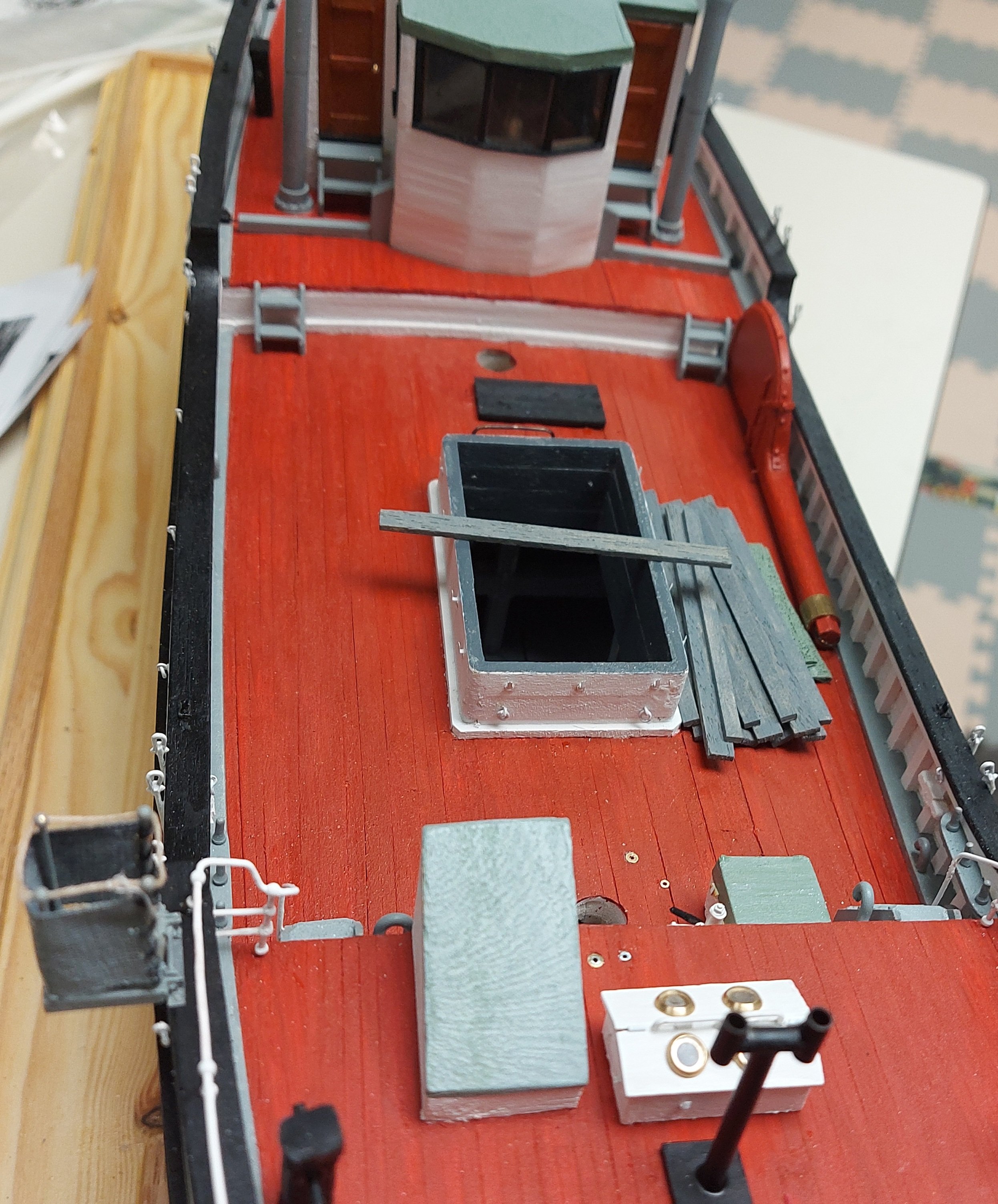
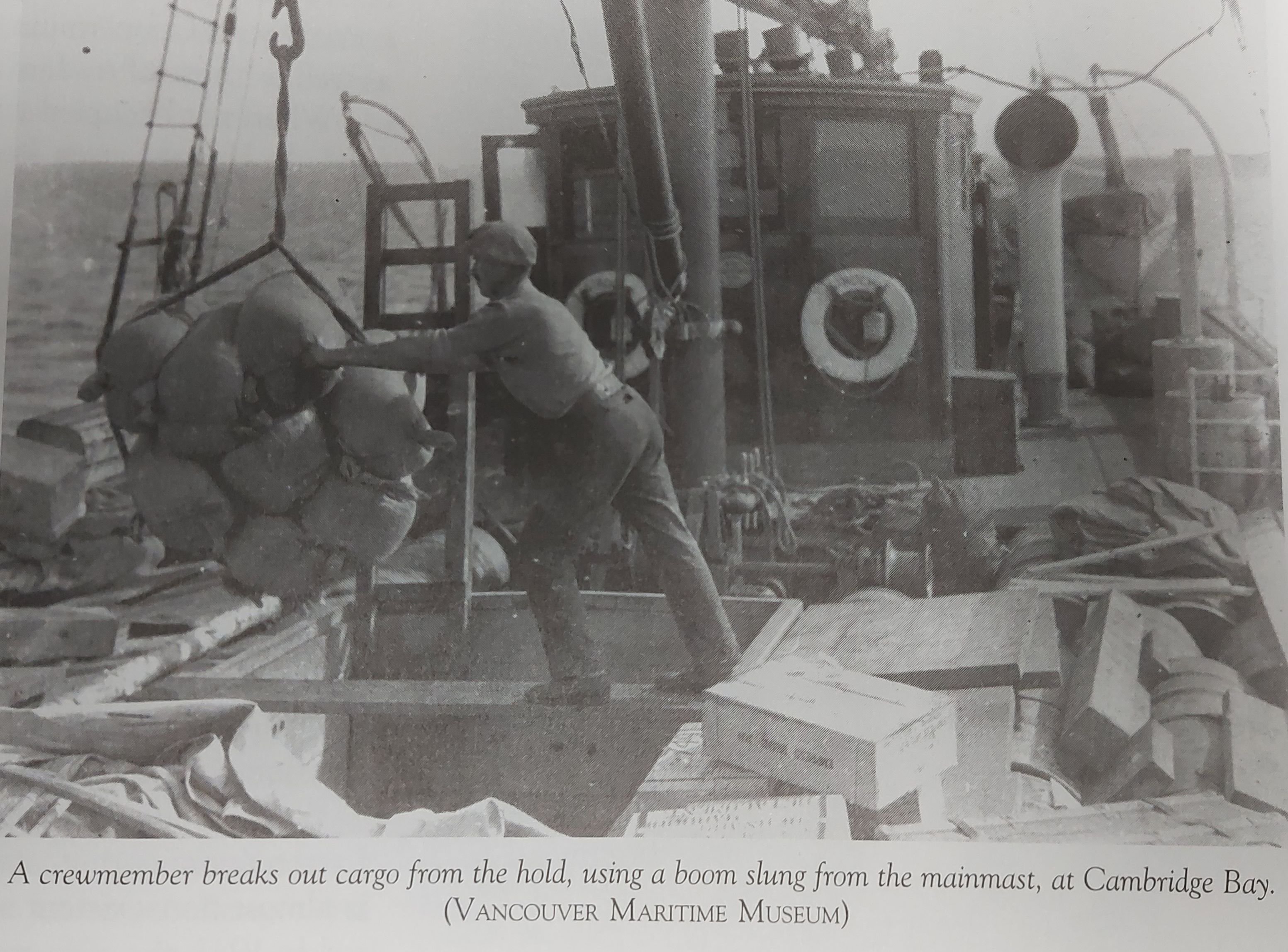
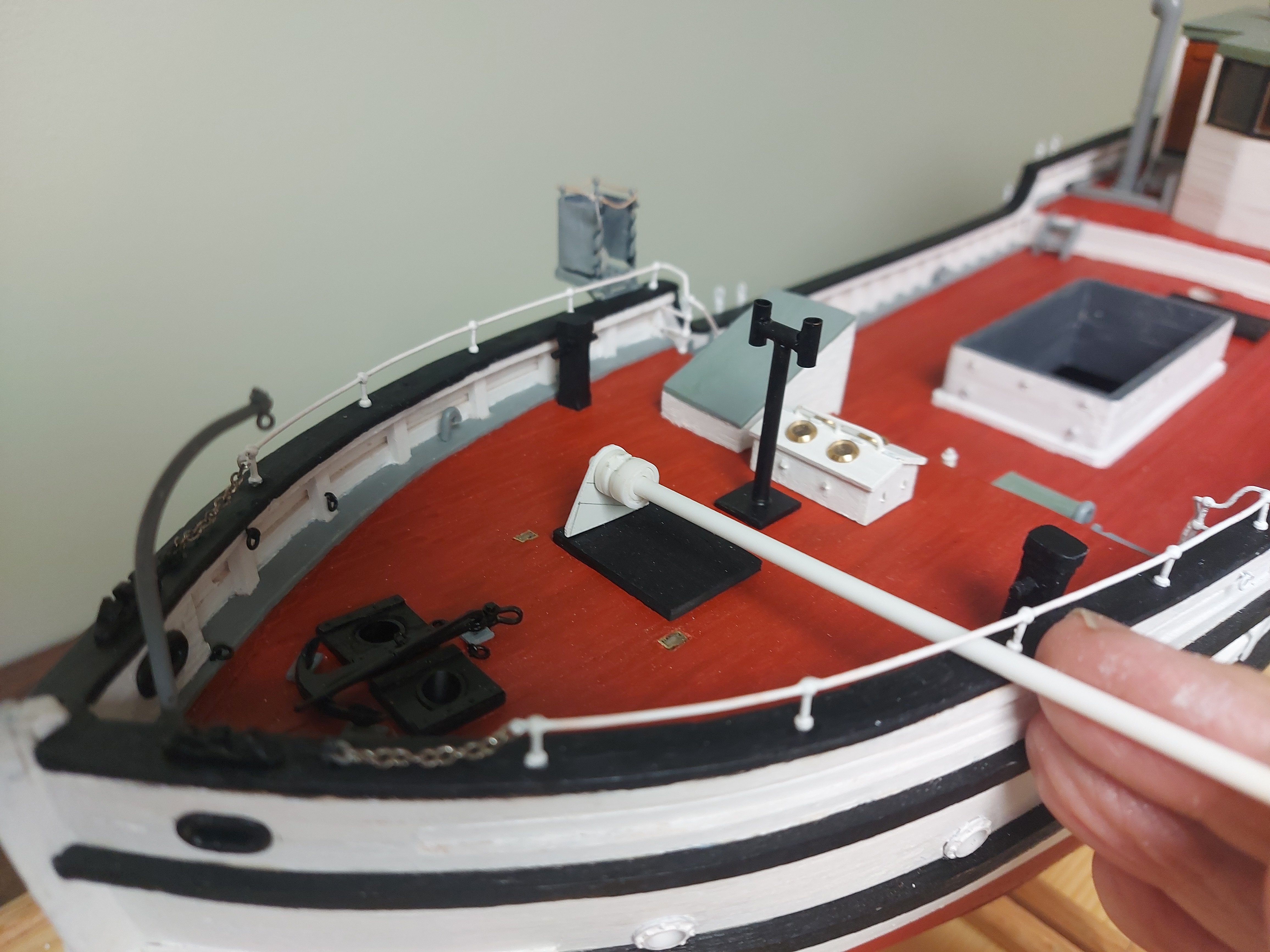
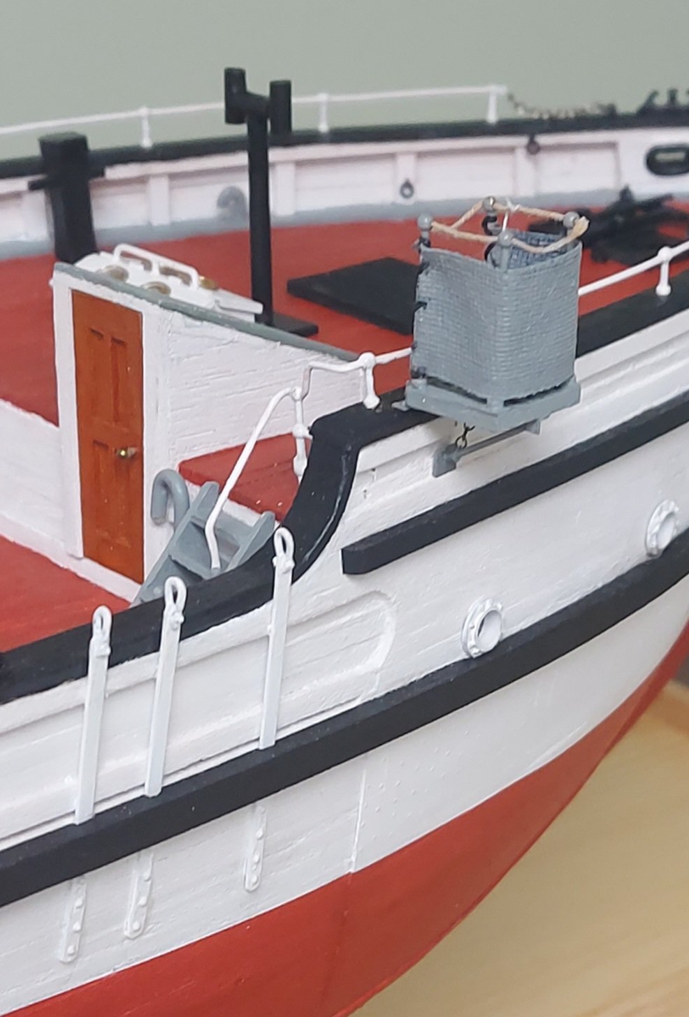
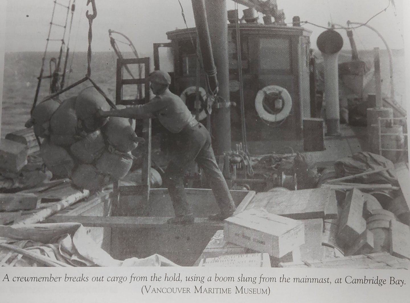
 The previous picture shows the spare rudder on the main deck. I note that the earlier photo of the crewman handling cargo does not appear to show the rudder, but it should be partially visible if it were stowed where I have it at the moment. It is important to note that the picture shows the original small deckhouse, so there would be more room on the poop aft. This main deck is where the rudder is stowed on the ship today, but it seems an improbable location given today's large, full beam superstructure! Without the mainmast the only possible way to get the spare rudder aft would be to use the foremast boom to lower it overside into a lifeboat, then haul it aft and sway it up using the mizzen boom! There is no room aft of the superstructure for it today... In the 1930s there is not much room on the poop as well, and I won't know for certain if the rudder can fit there until I make the lifeboat supports. However there is a passage along the waist from the main deck, and the mainmast with it's cargo boom could help move the rudder if necessary. Still working on this conundrum! Regards, Bruce
 -
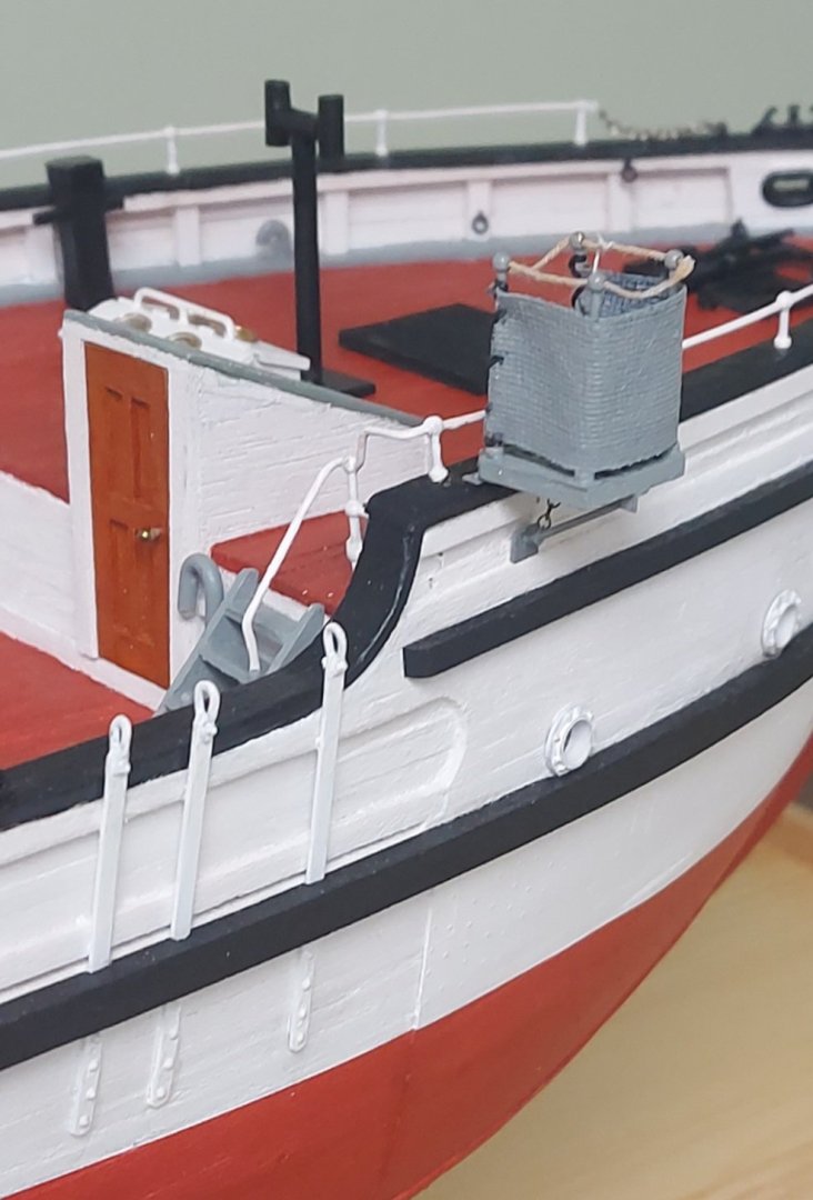
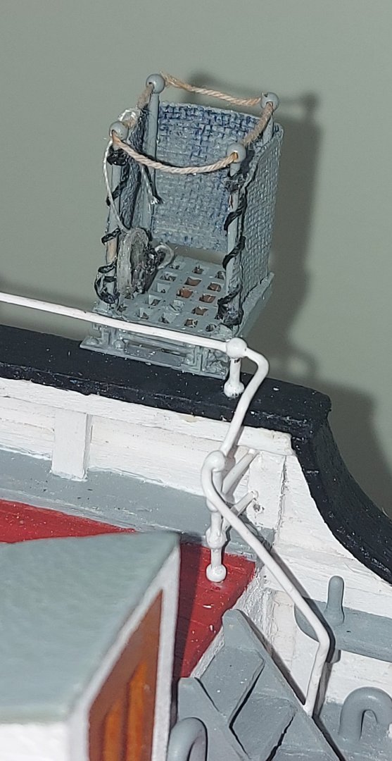
I have also made the canvas cover for the hatch, painted grey/green same as the other similar surfaces, and the hatch cover boards. This photo shows how I am thinking about displaying them, stacked up beside the hatch so you can see the strong beams down inside. These were a feature of St. Roch to prevent her being crushed in the ice, so I thought it important to show them. Referring back to the picture with the crewman, I am inspired to consider a diorama based on it. The main reason would be to include a figure that would give scale to the model. I did not do this for my previous models because I am crap at figure making and painting. I could also put some cargo in the hold, not enough to conceal the beams, and copy the use of the main mast cargo boom to give some action. I am not considering multiple figures or a lot of deck clutter, as I want to enhance the model, not detract from it. Any comments or suggestions on this idea are greatly appreciated!

- 368 replies
-
- 10
-

-
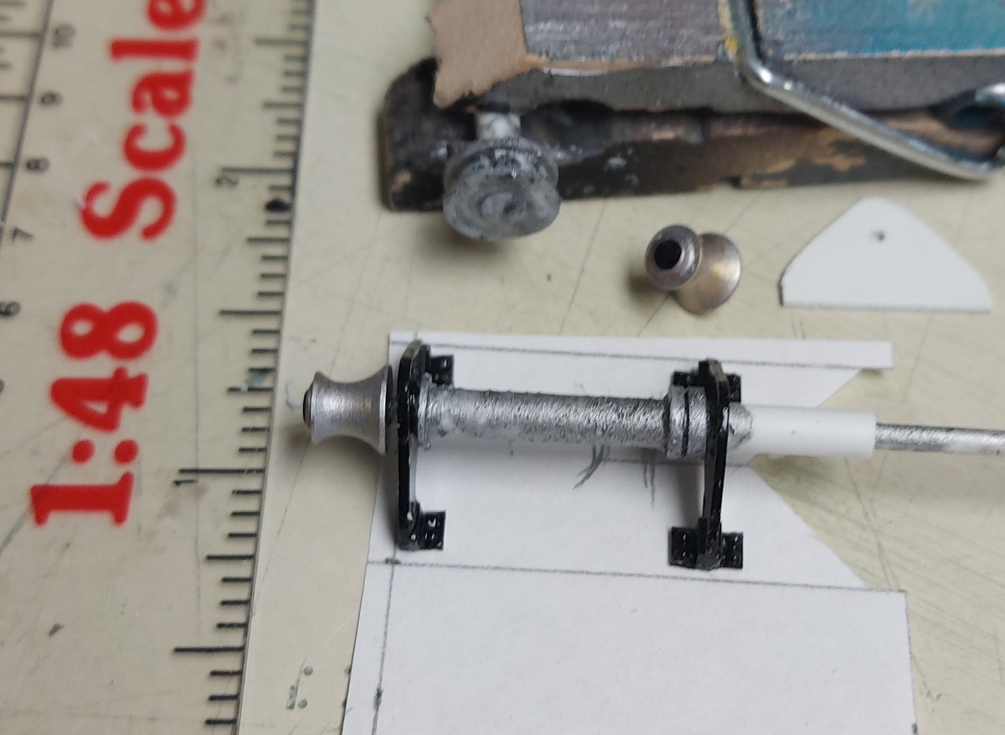
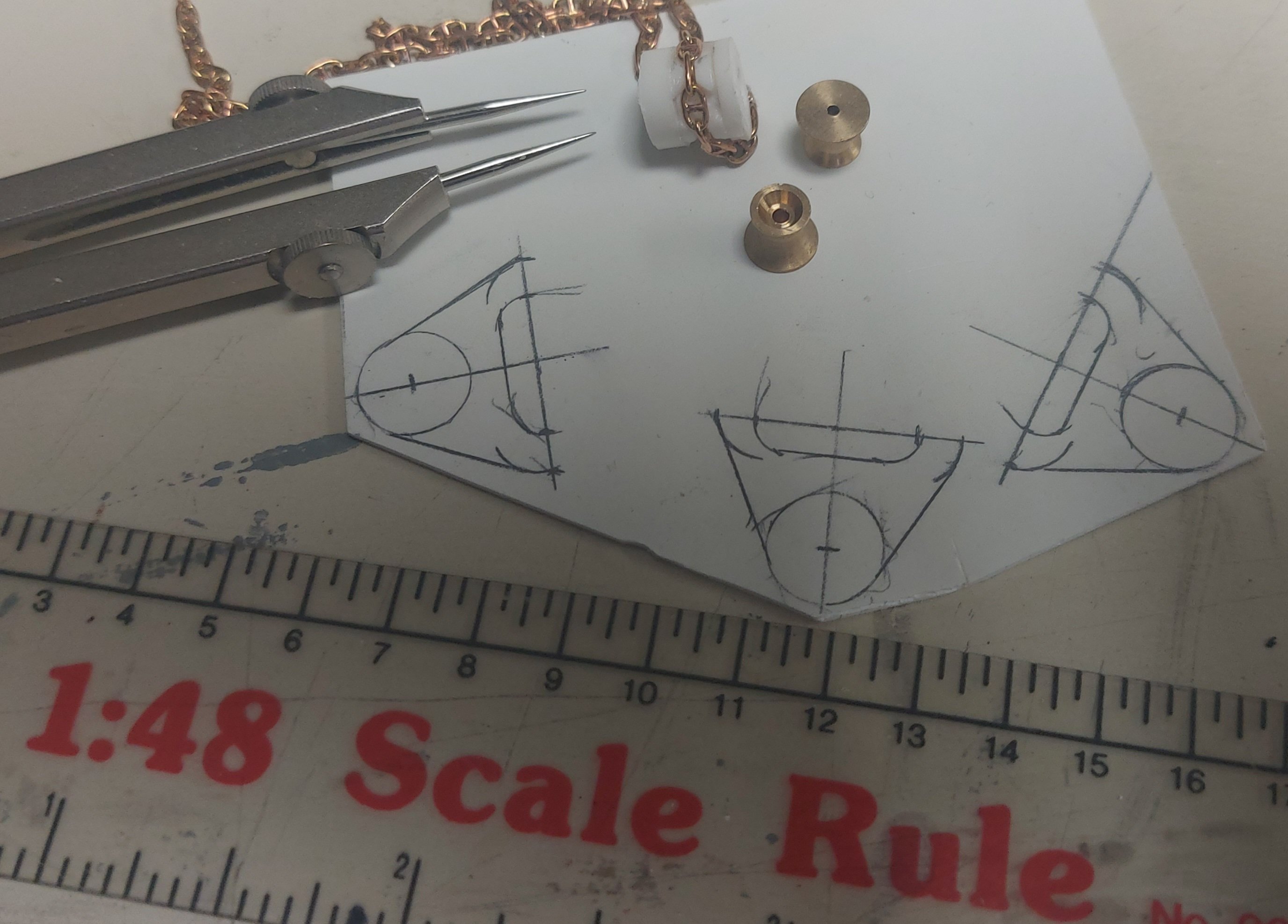
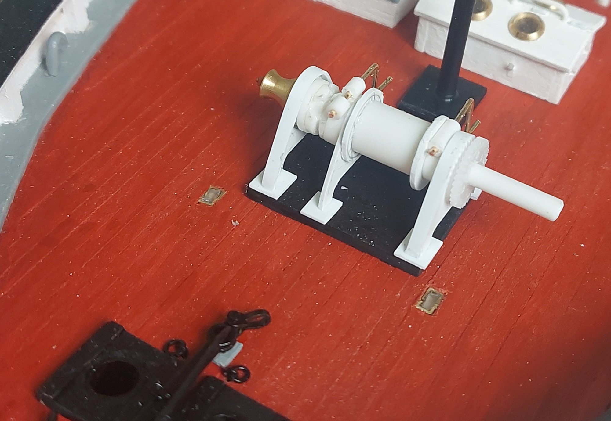
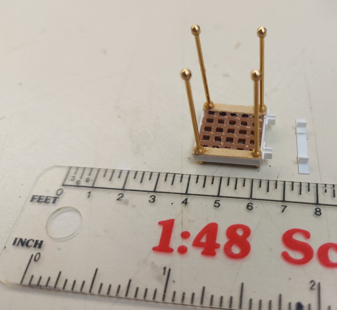
First up is the cargo winch, which I am recreating using what information I can glean from the previous picture and the sketch on the designer's 1928 plan... here are the pieces I am making so far... The winch is powered from a take-off on the main diesel engine, I have to work on the gears and shafts for that next. Thoughts, ideas, and comments are most welcome!

-
Good afternoon all, and I hope everyone is having a decent summer so far, as we are here in Alberta! I am moving on to detailing St. Roch's main deck... this work consists of making the cargo winch, the hatch covers, and stowing the spare rudder. First I want to share with you a picture from 1928 or 1929, from the book "Arctic Workhorse" by James Delgado. It shows a crewman breaking cargo from the hold using the cargo boom on the main mast. Of interest is the port side of the cargo winch in the background... you can see the warping drum, right next to it is what appears to be a pulley for the anchor winch drive, then a shaft to the cable spool and presumably the gearing in the background. This picture is informing my detailing of the main deck as described in the next posts...
-
Still waiting to hear from the Fram museum, but from information received from Harvey Golden and Wefalck I am leaning away from the belt idea towards a drive chain. Belt or chain, raising the cargo derrick, hence the guide rollers, would provide tension and act as a sort of clutch... I can always adapt the pulley on the anchor winch if necessary, but there is no information as to what it looked like on St. Roch. The missing link is the drive on the cargo winch, was there a separate gear that is not in my reference pictures, or was it wrapped around the warping drum? That cargo winch is coming up next on my list! Regards, Bruce
-
Thanks very much Harvey... I am still waiting to hear from the Fram museum, but your Gjoa thread is giving me a lot of missing details. You've also built a very nice looking model! Regards, Bruce
-
If it is not too late for your play, get a copy of James Delgado's book "Arctic Workhorse" from the Vancouver Maritime Museum's gift shop. It gives a good description of RCMP schooner St. Roch's time in Arctic service including both her NW passage transits, and the life of her crew on board. Regards, Bruce LeCren
-
Thanks very much Wefalck for checking! I saw a model of Gjoa that has rollers on the side of the deckhouse, but I am not attributing too much to their accuracy. They would likely have been used to carry the chain or belt between the winches. We would have some time on the afternoon or evening of August 16, other than that Viking has filled our itinerary. If not this time, then next! Regards, Bruce
-
Thanks for everyone's help with my anchor winch drive. Today I wrote to the Fram Museum in Oslo, custodians of Maud from whom St. Roch's lines and Arctic construction features were taken by naval architect Thomas Halliday in 1927. The museum also has the exploration ships Gjoa and Fram, either under restoration or on display. Since they have the machinery from these ships I hope they can be my arbiters on St. Roch's winches. Regards, Bruce
-
Bonjour wefalck! Fair comments, and valid, thanks for your input. It could very well have been a chain, and that was my first thought until I looked at the cargo winch pictures... and while they are not very good I could see no means of connecting a chain to that winch (which drives the anchor winch). I would be very interested in seeing pictures of chain drives... St. Roch would not have been the only ship with mechanical drive! Regards, Bruce
-
I lashed down the stream anchor and completed the anchor and winch installation... there are 86 individual parts making up the winch not including the anchor cable and chain! From all the pictures I was able to find (thanks AON!) I figured that the winch was manufactured as a unit and the mechanical drive added later to suit the ship. Other than the drive coming from the cargo winch on the main deck there is no other information extant. It could have been a chain, or a belt. The overall looped length would be 80 feet (25m). Similar belts were used at that time to drive agricultural machinery from traction engines, so I think this is a real possibility. Also, I do have two pictures showing the port side of the cargo winch... there is a warping drum, but no gear or pulley, therefore I made my anchor winch drive pulley to be able to take a belt. My decision to own and defend! The anchors are not glued to the hull, but hang on their chain or cable. I made the pelican hook and cable gripper by modifying miniature turnbuckles and adding eye bolt and wing nut details. This completes the work on the fo'c's'le deck, now on to the main deck, where I will be making the open hatch cover, cargo winch, and possibly the spare rudder stowage!


-
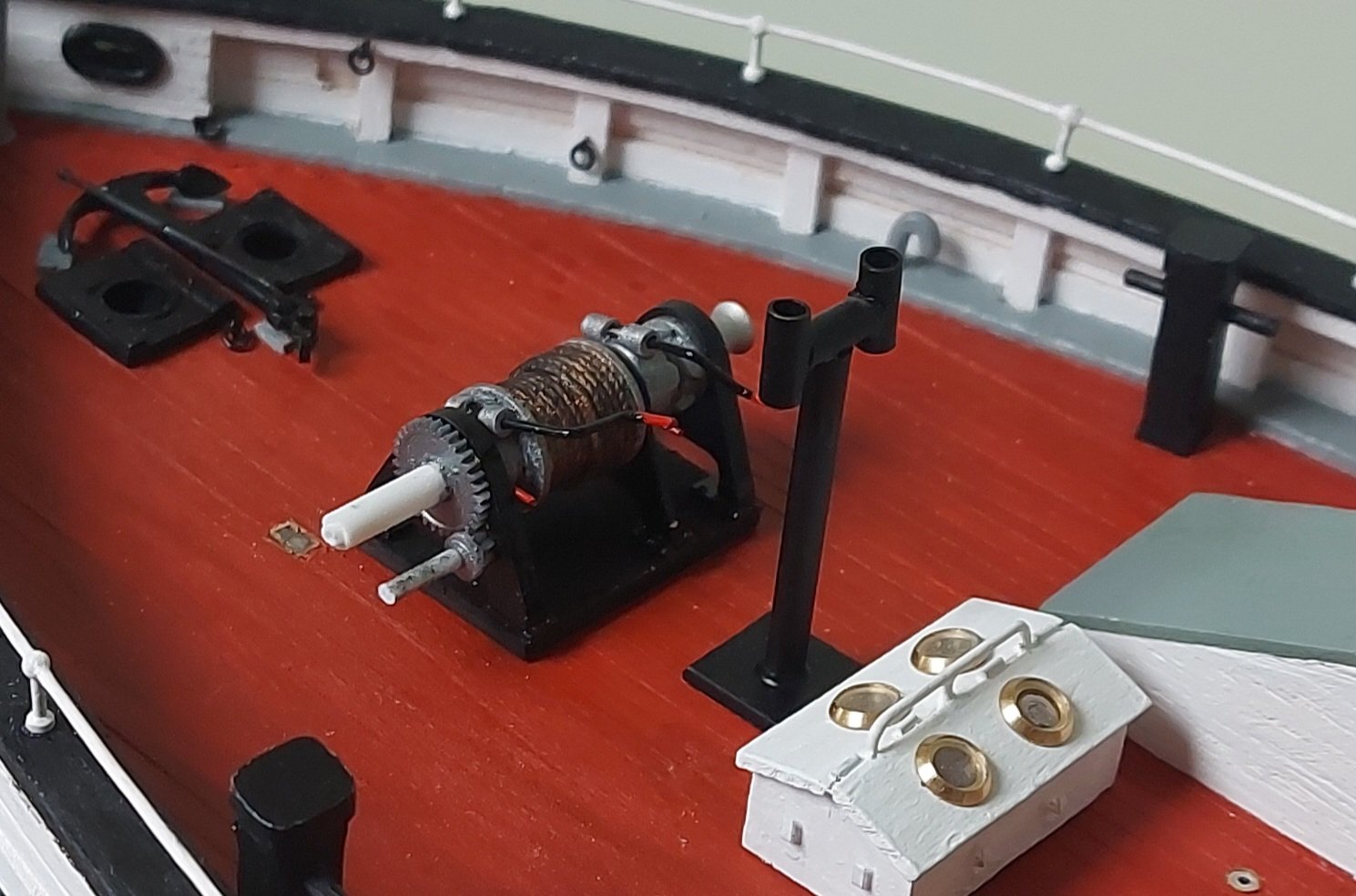
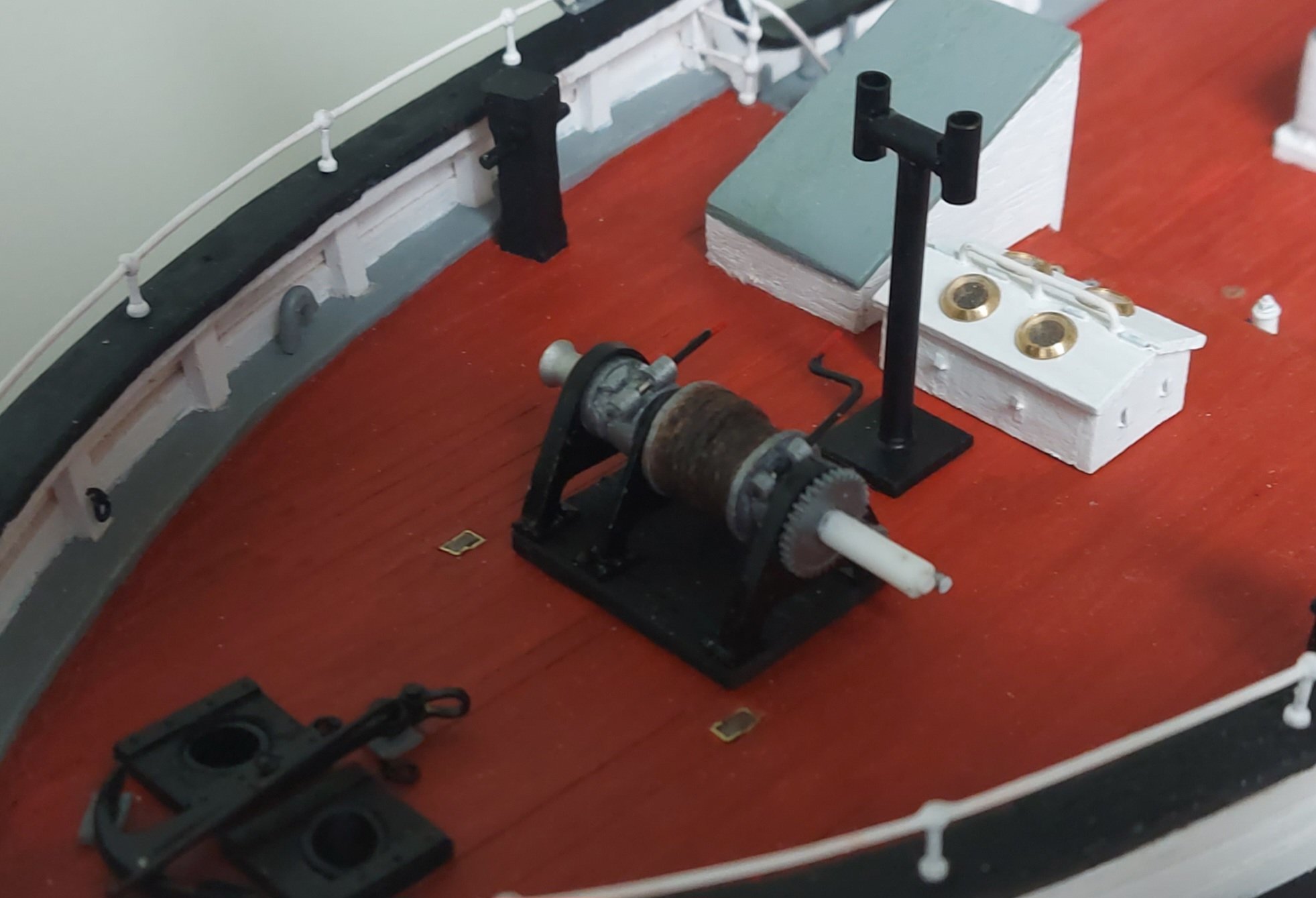
Nearly there... as per my earlier thoughts, I painted the rotating parts gun metal. The warping drums are flat aluminum. I wrapped the cable spool with suitably sized rigging thread from my stash to serve as the port anchor hawser, then I dry brushed Tamiya X-1 gloss black, followed by Vallejo rust, and lastly Tamiya XF-1 flat black. I think I achieved the look of wire rope?? The drive gear shaft extends out so the drive clears the hatch on the main deck... I have to make a supporting frame and pulley for that. My 1928 plans sketch shows the port warping drum also extending on the winch shaft... not sure if I will do that yet. It will depend on if there is room to wrap and unwrap lines once the drive pulley is on. As always, thanks for checking in and feedback is appreciated! Bruce


- 368 replies
-
- 12
-
-

-
Thanks a bunch Alan! There is enough information there to let me fabricate a replication of a cable gripper... Regars, Bruce
-
OK, I need a nickel's worth of free advice from the forum folks... The weight of St. Roch's anchors should not be borne by the anchor winch when not in use. For the starboard chain, I have no problem making a pelican hook to fit on the chain, but what about the port anchor cable? I have no idea what a cable gripper would look like a hundred years ago, and there is no bitt on which to belay the cable. Does anyone have any drawings, pictures or references to how I might include a period correct cable gripper? Thanks in advance, Bruce
-
Thanks Phil, that's a resource I had not considered! The winches were made by Pumps and Power of Vancouver, I'll try a search and see what comes up! Regards, Bruce
-
Thanks Kurt, I appreciate the feedback! Still musing about the dog clutch... Regards, Bruce
-
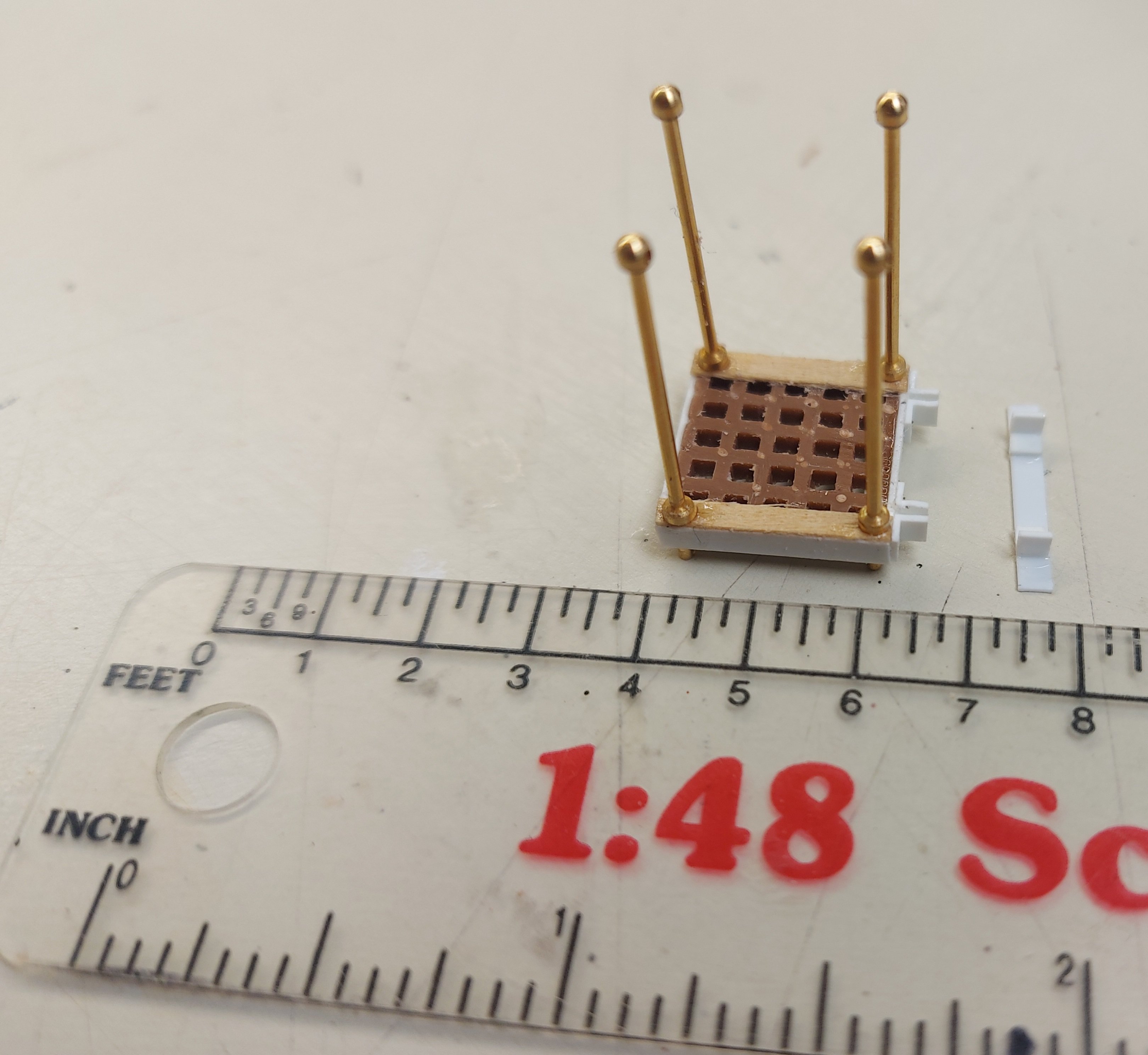
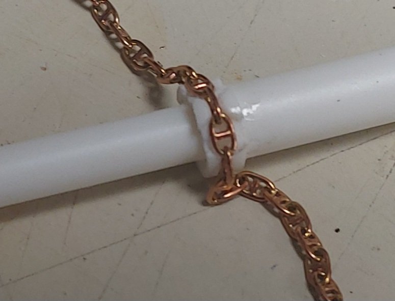
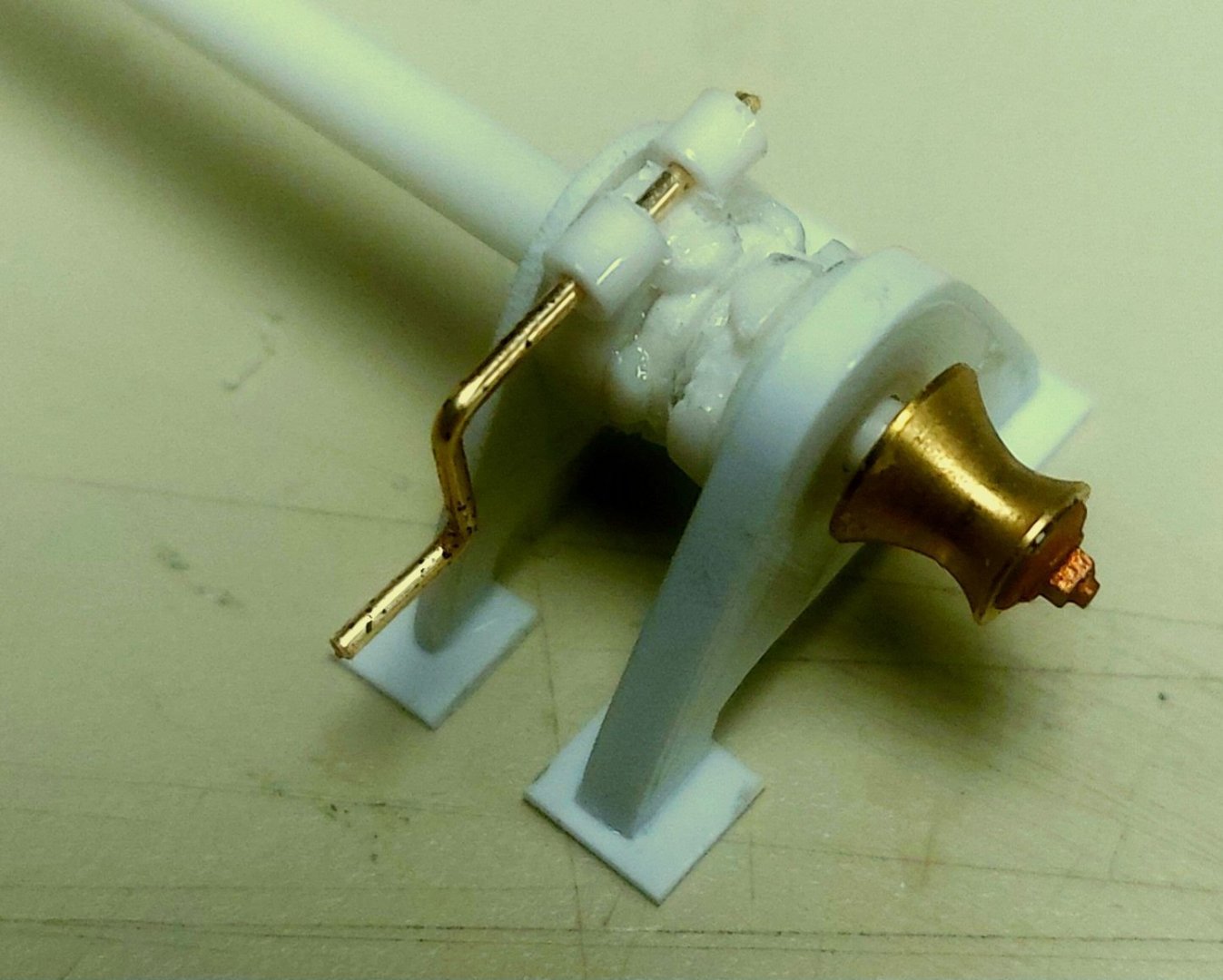
I am using stud link chain by Krick for the anchor... expensive but the look of the stud links goes, in my opinion, a long way to completing the finish in this scale. Starting with the chain, the first thing to make is the gypsy... I used three sizes of nested styrene tube, cutting away whatever did not look like a gypsy until I was satisfied... From the final size of the gypsy I scaled three winch supporting frames onto a piece of scrap styrene... And test fit to the ship. I am checking here for size... does it look right in the absence of plans or photos? I will thin down the gypsy on one side, the wider side will become the brake band. The warping drums are by Billings Boats, they are correct for size so it was easier to buy the four I will need as opposed to turning them myself. Here are the parts so far, test fitted onto the winch shaft... You can see the brake band and crank, and the warping drum is finished with scale hardware from Grandt Line. The frame on the end has a flange for strength. Details like this are my conjecture, in the absence of plans or photos of St. Roch's winch... Now I turned my attention to making the remaining end frame and the cable spool. I had to be careful here to ensure the winch was not going to outgrow the base, which is already mounted on the deck! The cable spool gets its' own brake band. It is time to go to my stash of old RC servo gears and find some that would look proper to make the drive assembly... This last picture shows everything so far, test fitted together on the ship, with the drive gear on the end of the shaft. There are some adjustments needed to fit the base, then it will be time for paint and assembly. I am thinking of black overall, with gun metal on the rotating parts for contrast, and maybe a rust wash on the cable and chain, again for contrast rather that weathering purposes. I still have to make the final gear drive and pulley assembly, and am trying to think good thoughts about how to include a dog clutch, or whether it would be better to leave it off?? Thoughts, comments, and critiques are always appreciated, especially as I am making a lot of it up as I go along! Regards, Bruce


- 368 replies
-
- 13
-
-
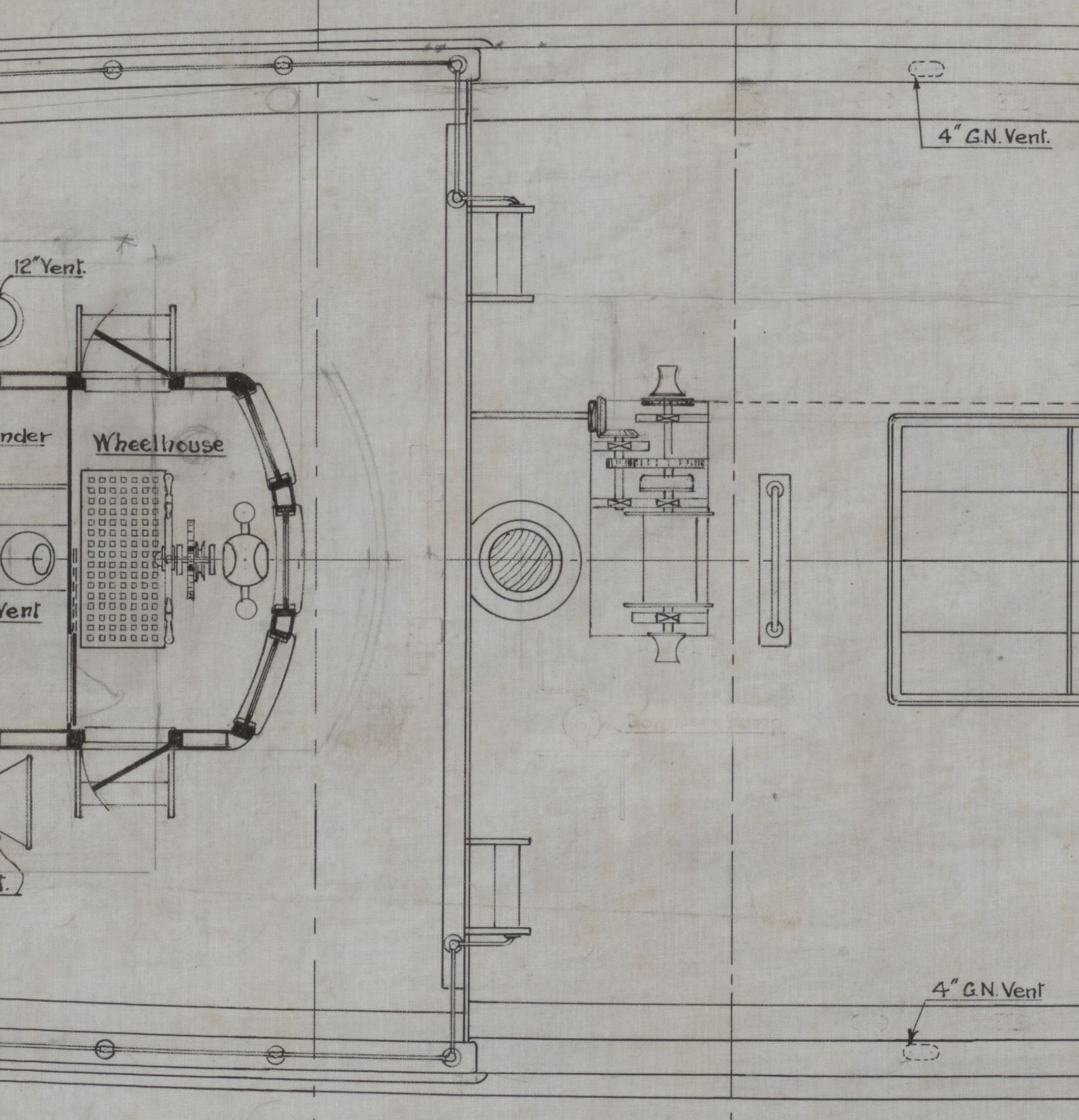
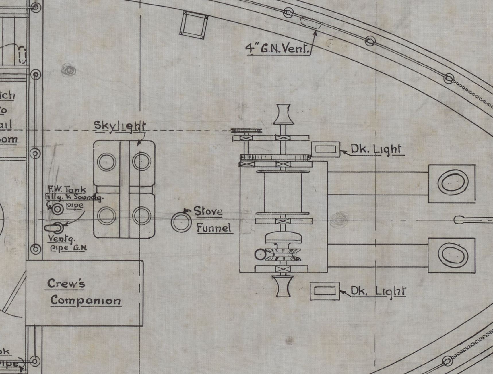
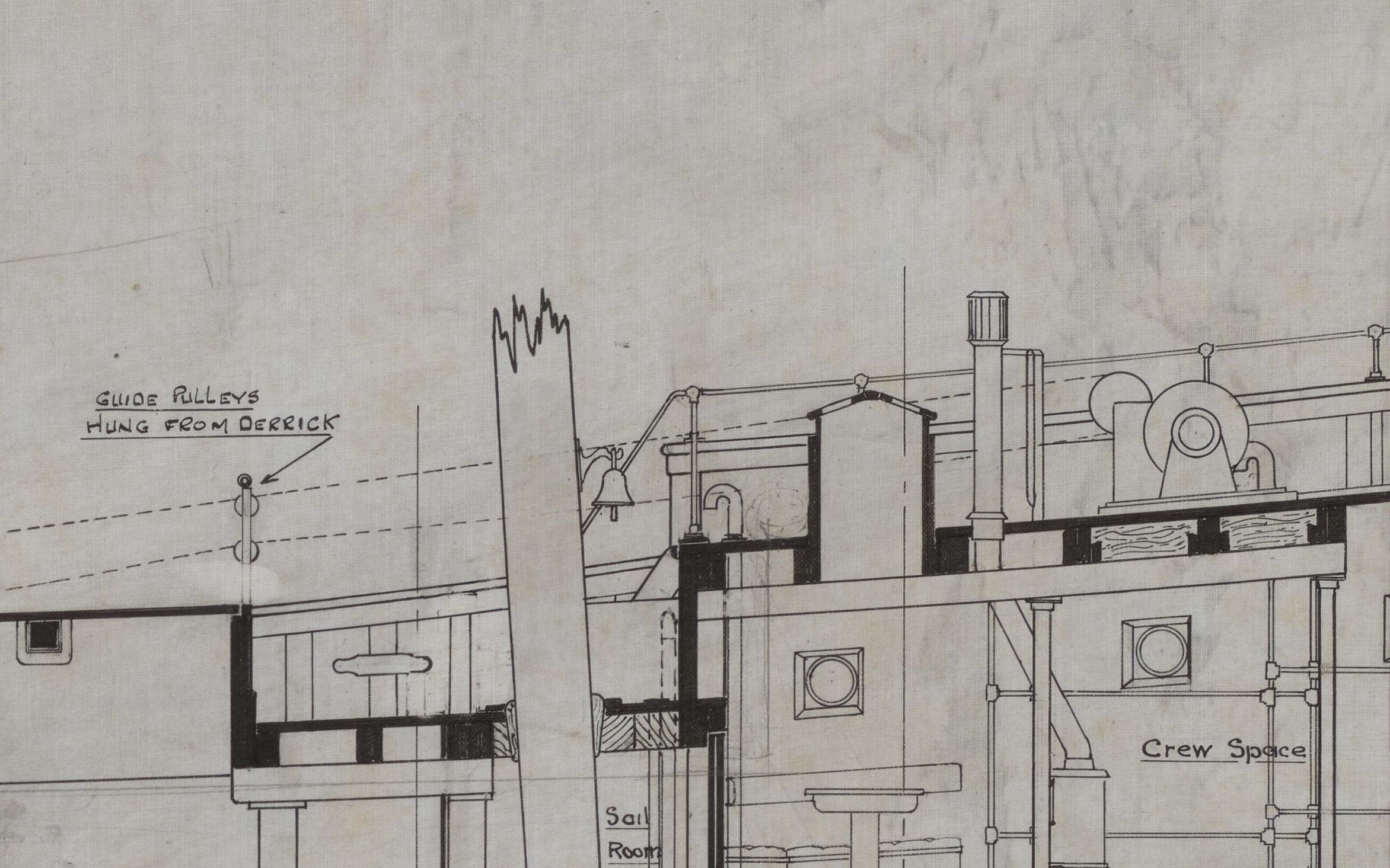
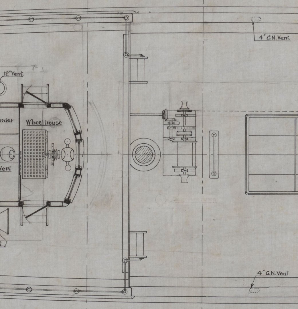
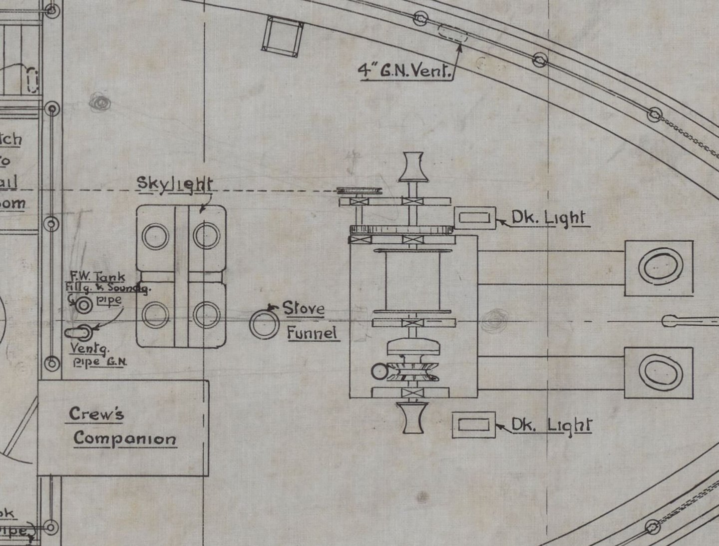
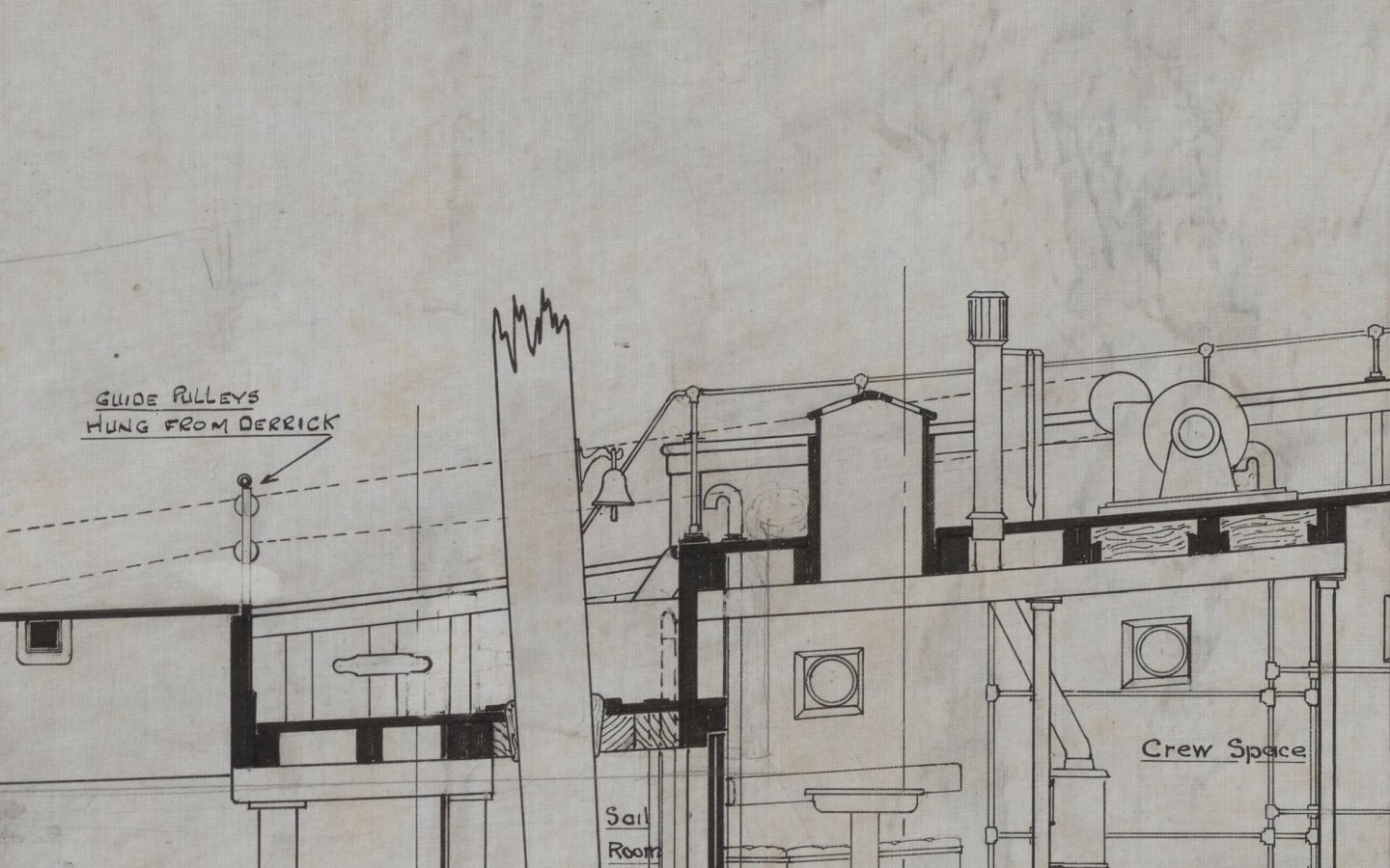
Building the anchor winch is going to be very interesting, because there are no plans or photos of it in existence! The attached portions of the 1928 designer's plan give a side view and a plan view of what was envisaged: a winch having a chain gypsy on the starboard anchor, a cable spool on the port anchor, and a mechanical gearing that drove the winch from a power take-off on the main engine, via the cargo winch at the foot of the main mast. After the maiden voyage Captain Larsen complained that the winch was under powered, and it was replaced in 1930. It was replaced again in 1944 by the one on the ship today. Here is the plan view, it shows the driving gears off the winch base on a separate support... but was the same arrangement kept in 1930? Who knows!? Here is the side view, showing a drive chain or belt to operate the anchor winch from the cargo winch, and a pulley set slung from the cargo derrick to guide the drive. I decided to follow the plan view more or less as presented, because the 1930 winch was still mechanically driven, and to keep the drive clear of the cargo hatch it would have to be extended to port with a separate support as shown on the plan. I did try and search out period plans or photos of other mechanical winches, without much success... if anyone has information or suggestions it would be great to hear from you!
-
Thank you Phil, much appreciated. Here is a picture of the prototype... Regards, Bruce

-
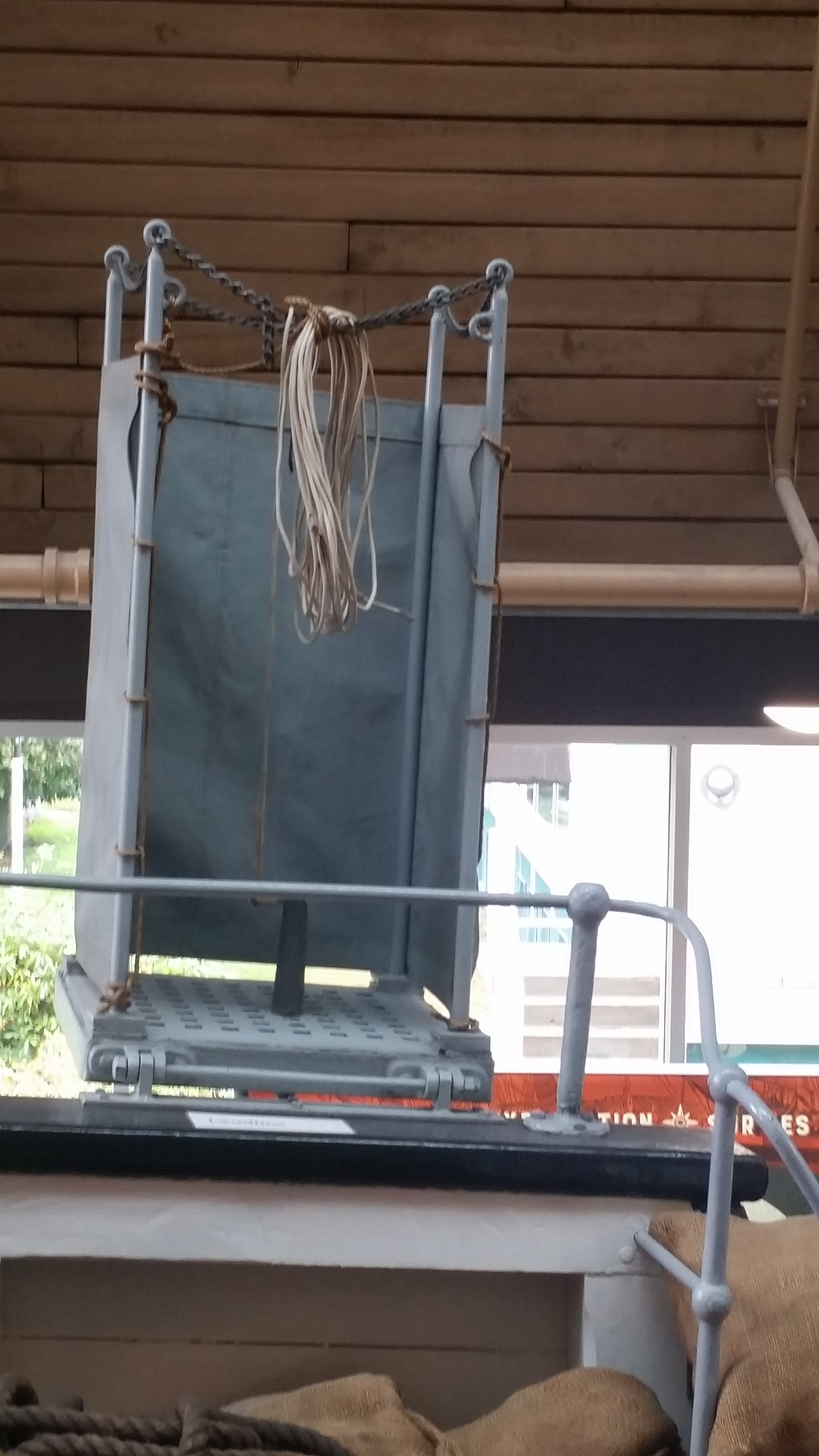
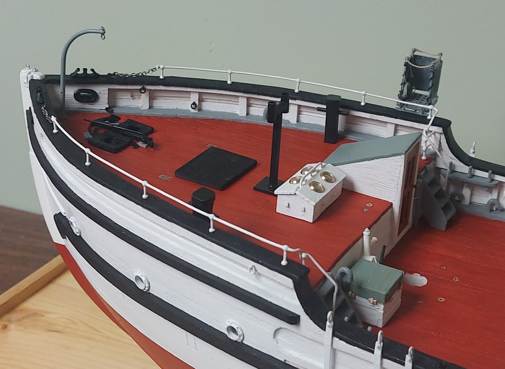
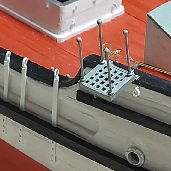
It has been about 2 weeks since my last update, and co-incidentally since I got my second knee! I'm now able to use the basement stairs, despite admonitions from SWMBO not to overdo things, so I was able to get a start on my summer to-do list! First up is to build the small platform that extends out from the starboard fo'c's'le. Photos show this was added by the crew in 1929 during St. Roch's maiden voyage. She spent much of her career sailing through uncharted shoal waters, and Captain Larsen wanted a place from which to swing the lead and communicate easily with the wheelhouse. Design plans show a sounding machine on the poop deck, but there is no information that it was ever installed. Larsen makes no mention of using it, and I am sure he would have found the location unsuitable for reporting soundings. I am not including it. The first photos show the sounding platform being roughed out on my bench, then trial fitted on the ship... The platform is hinged to the hull and there is a chain holding a brace in place underneath. The last photo shows the platform complete with the lead line... The fo'c's'le railings are visible in some of the previous pictures, this next photo shows the starboard rail being formed... Finally, here is an overview of the fo'c's'le deck with the rails and platform. The rails are not painted white today, but period photos from 1930 to 1934, while b&w, show a very light colour, so I painted mine white. It is time to build the anchor windlass and install the anchors before moving aft to finish the hull... As always, thank for checking in and comments are always welcome!

- 368 replies
-
- 13
-
-
-
Thank you very much Steve. Thanks for following along, enjoy your summer too! Regards, Bruce
-
Thank you very much! I will be checking in from time to time when I get a bit more done! Regards, Bruce
-
Thank you Keith! This will be our family's 18th annual fishing trip to Tobin Lake... I hope to make some more progress in between bouts of relaxation! Regards, Bruce
-
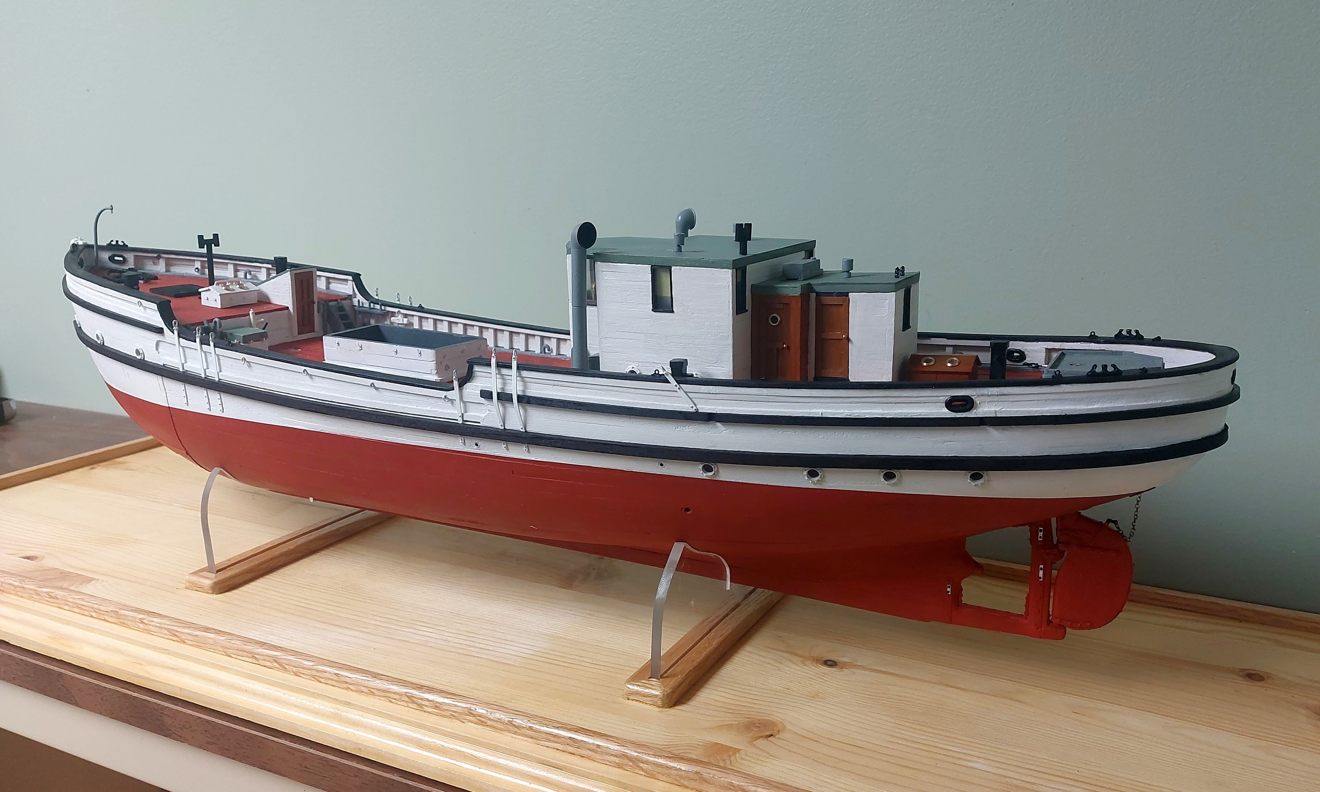
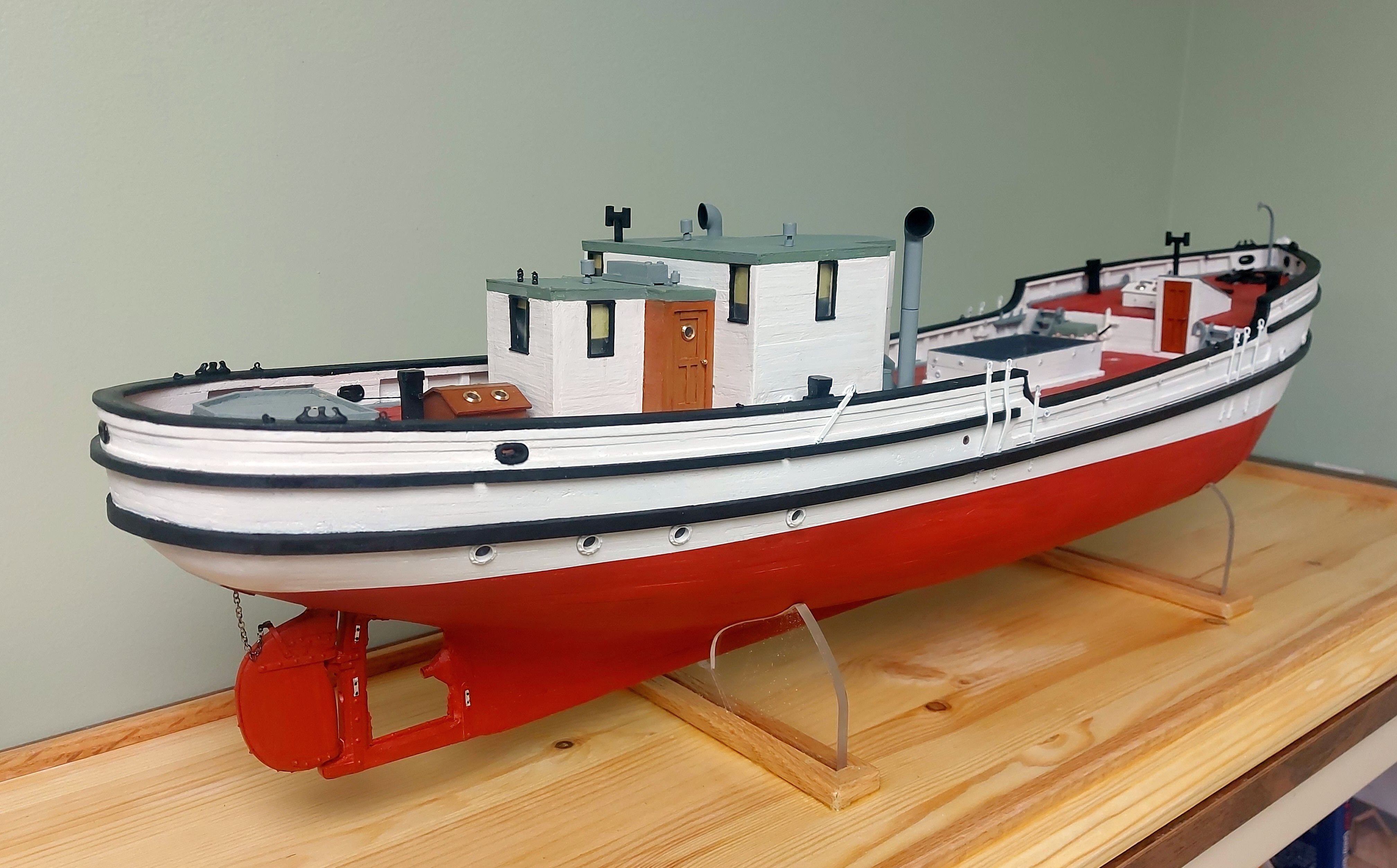
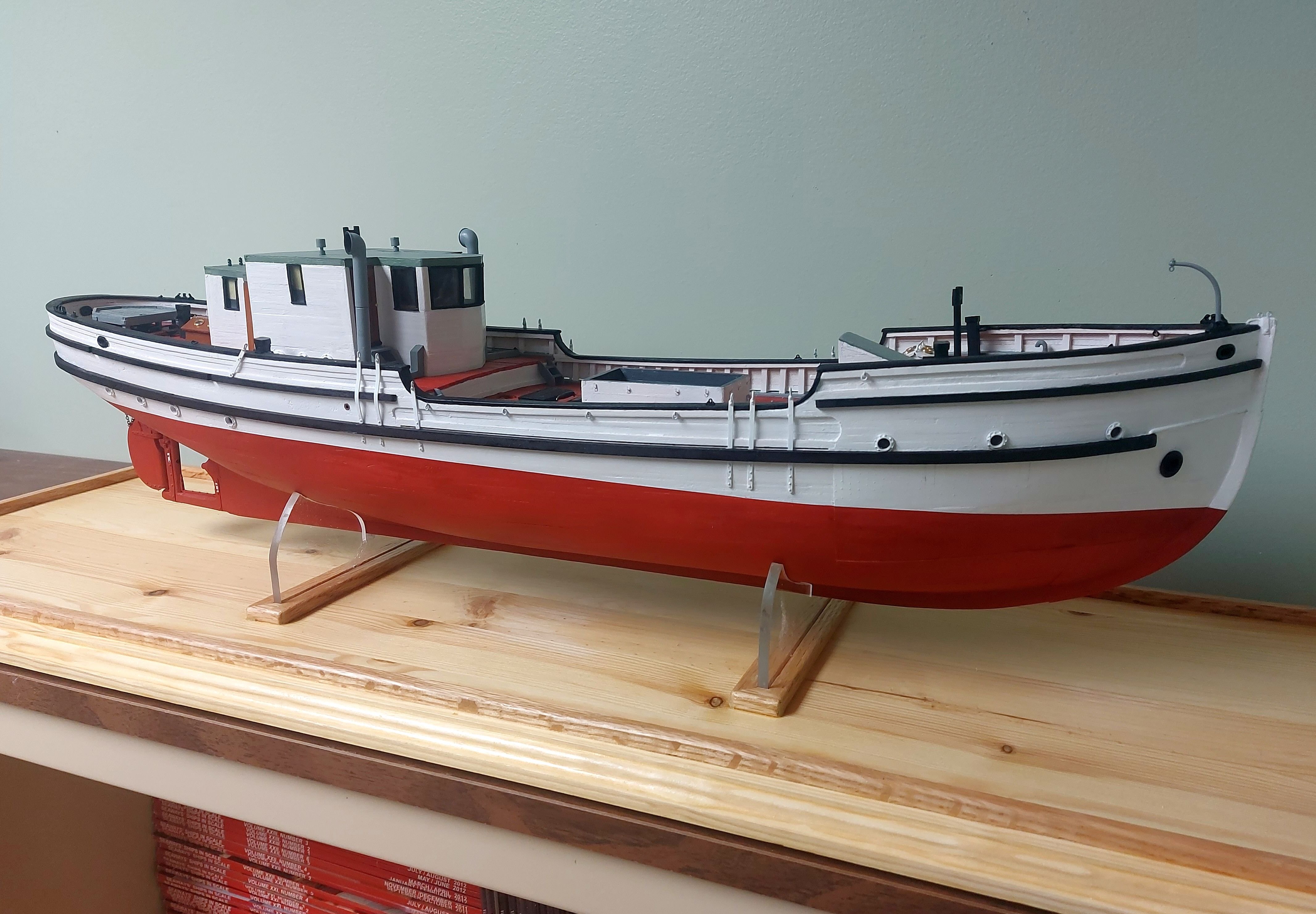
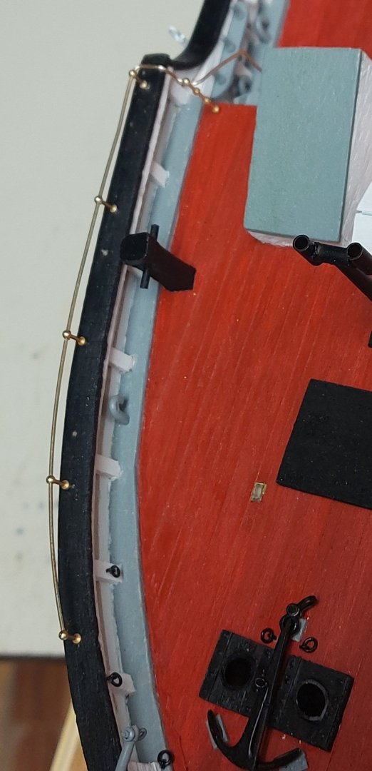
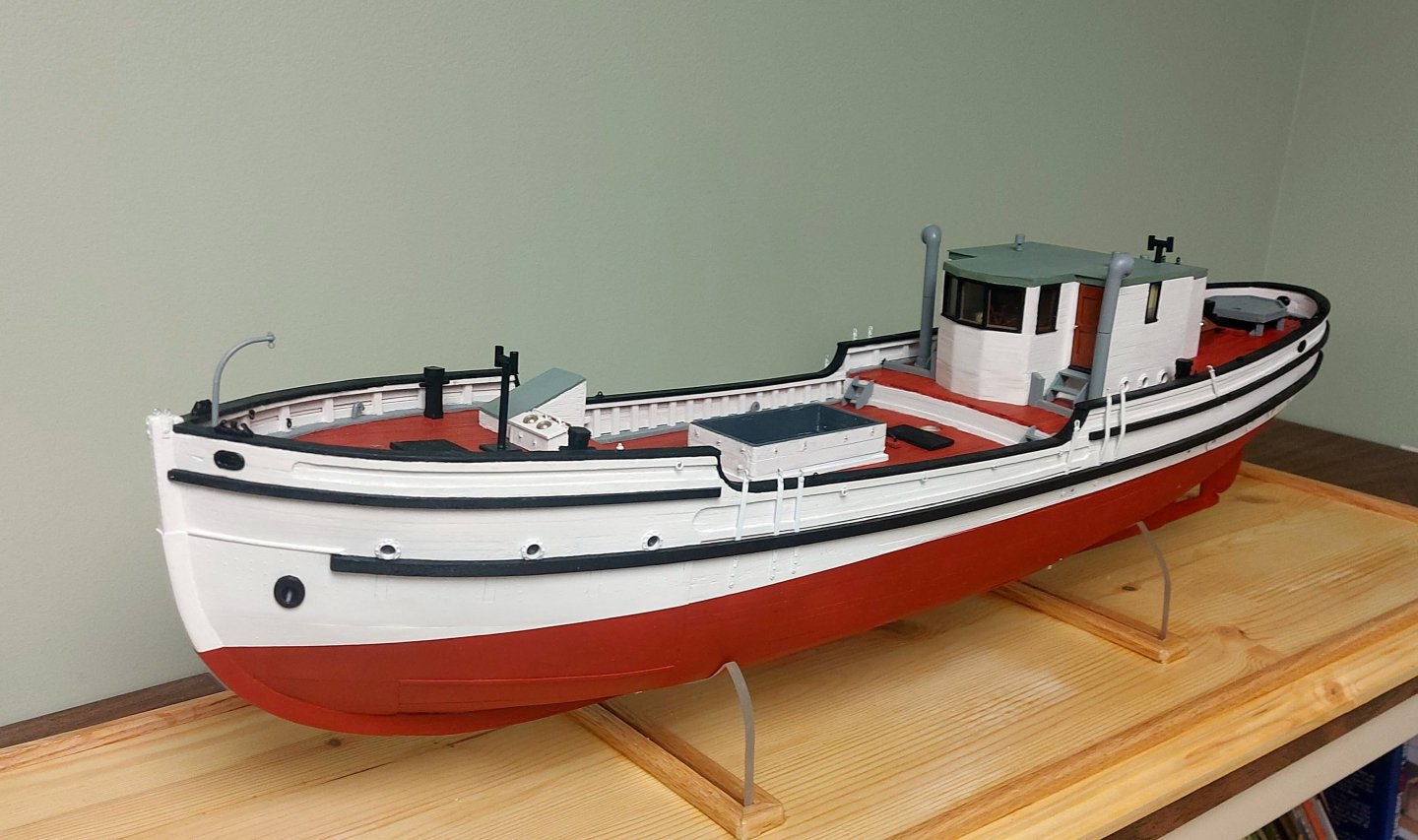
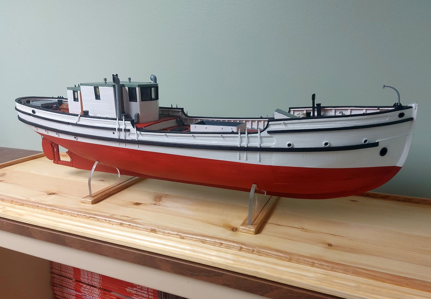
St. Roch is now mounted on her display base... I still have a list of about a dozen items to make and install before the hull is complete, things from the ship's boats to the decals. Much can be done off the model and completing these items will be my goal for the rest of the summer. That's one of the things about scratch building... you have to think ahead and make up your instructions as you go along, and hope Part A fits into Assembly B before Widget X gets in the way (as it inevitably will)! I have also made some decisions as to St. Roch's display. Apart from some old Revell kits I made about 50 years ago, this is my first model sailing ship. I have decided to show her sails furled, so as to include all the running rigging while not impeding the view of the deck. New skills to learn, and I have picked up David Antscherl's Appendix on sail-making for some light bedtime reading! St. Roch has a very simple rig which I hope even a tyro such as myself can handle! I have also decided not to weather the ship, or clutter up the decks with odds and ends, as the ship is displayed today. This is a model, and my focus is to display the ship herself. Anyone who has followed this build log will have seen the warts on my hull and paint; but St. Roch is (or was) a working schooner that saw hard service, so to that end I am leaving the divots and scratches, as these were, and are today, present on the hull. Despite that she was well maintained by her crew of R.C.M.P. Constables, who took a great deal of pride in their ship, so I am leaving the hull free of rust and detritus. Keen eyes will note on the two previous pictures the zinc anodes, installed on the forged steel rudder reinforcements. Also the various inlets, discharges, and exhausts have been drilled through the hull and lined with pieces of brass rod. So now I am going fishing, then in June I'll be getting my other knee replaced, and making a pilgrimage to France in August (my Grandfather was with the 38th Bn at Vimy Ridge, and my wife Dale's father came ashore at Juno Beach), so I will be away for most of the summer but I will check in from time to time! Thanks for following along; I would appreciate hearing from others how you arrived at your decisions as to how to display your models... Regards, Bruce


- 368 replies
-
- 15
-
-