HOLIDAY DONATION DRIVE - SUPPORT MSW - DO YOUR PART TO KEEP THIS GREAT FORUM GOING! (Only 20 donations so far - C'mon guys!)
×


Lecrenb
-
Posts
262 -
Joined
-
Last visited
Content Type
Profiles
Forums
Gallery
Events
Everything posted by Lecrenb
-
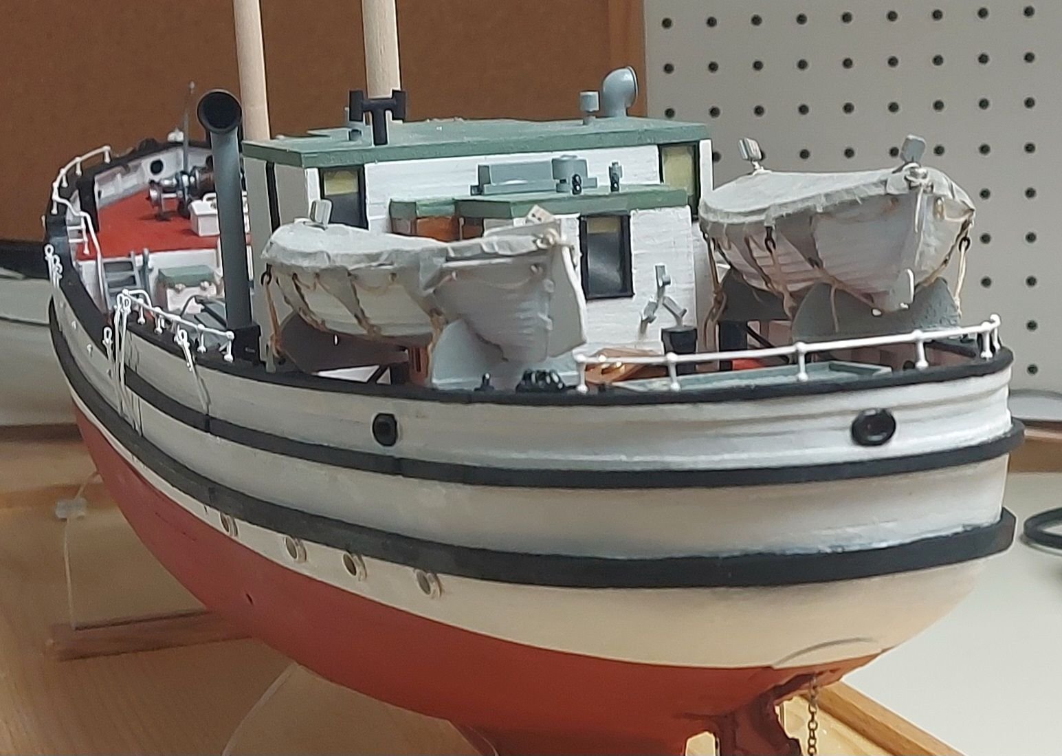
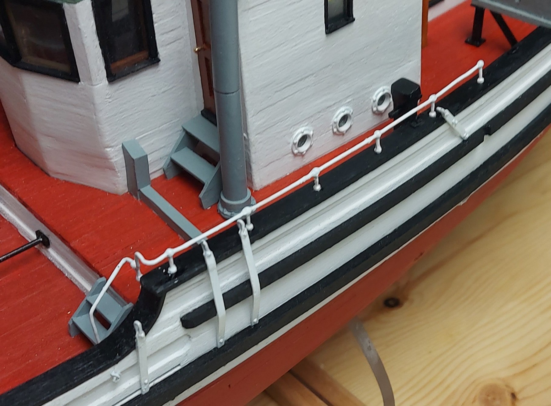
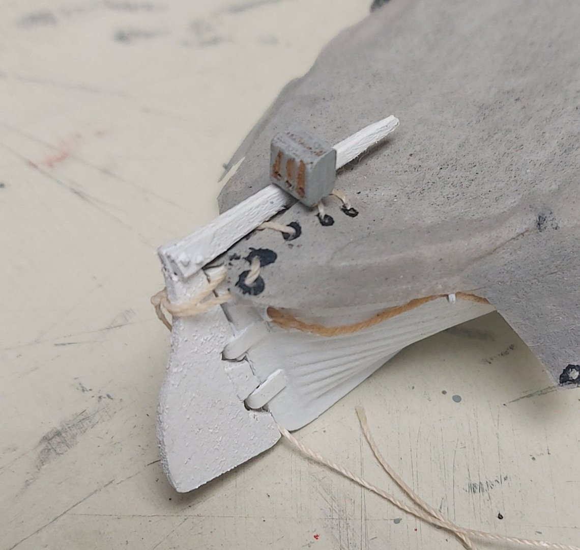
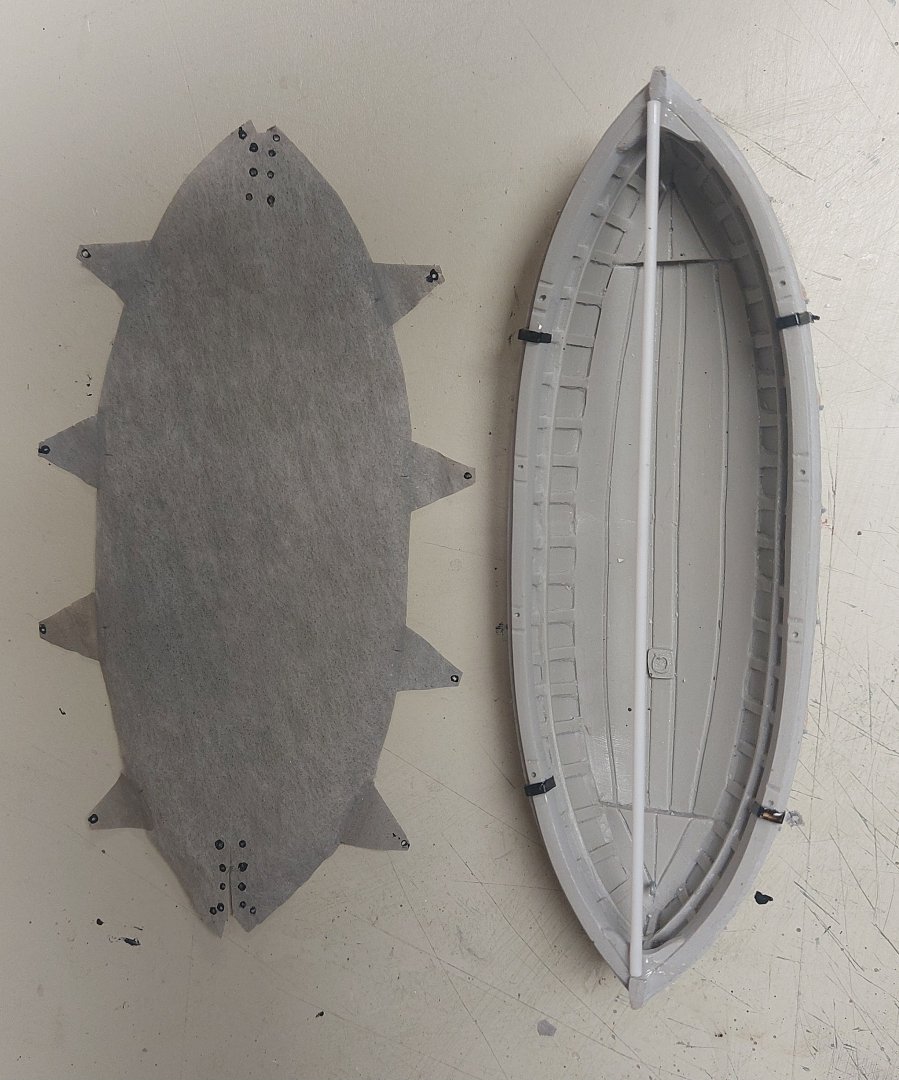
 Also outstanding was the location of the spare rudder. With the boats and falls rigged there is not much room left on the poop deck, although the rudder will still fit under the boat cradles. It would be very difficult to handle the rudder if it was needed, so after discussions with the Vancouver Maritime Museum I decided to stow my spare in the ship's waist, as it is displayed today. The main mast cargo boom and main boom would both aid in moving the rudder aft for replacement. I took advantage of the scuppers and outboard rings to lash the rudder securely to the bulwarks. I have to confirm with my references whether or not to make a wire rope reel for the foredeck. St. Roch has two today, installed at different times during her career. Other than that, the hull is finished and I am moving on to locate where the various bands and fittings go on the masts. Thank you everyone for looking in and contributing helpful hints and suggestions! Regards, Bruce
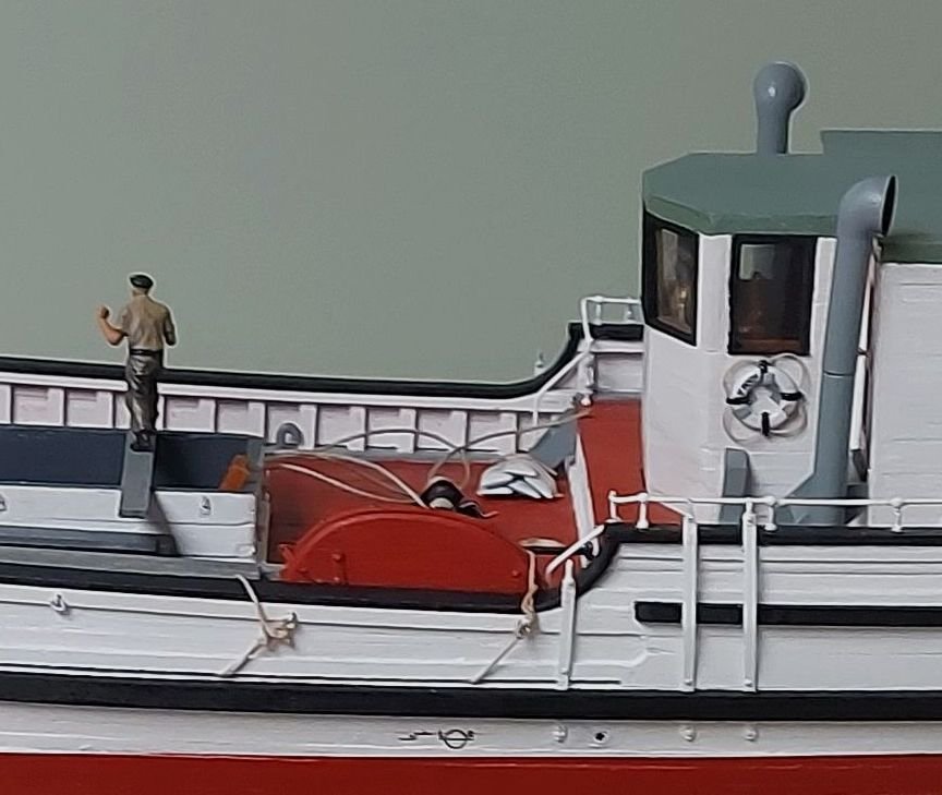

- 368 replies
-
- 11
-

-
Next I fixed the fuzz on the boat falls by following Kurt's suggestion, except I used 'No Sew' and an old brush with flayed bristles... this got in between each of the triple lines with one pass. Then I added the davit stays. Each starts at a ring or eye, and ends at the next ring or eye with a round turn and two half hitches. The bitter ends are left slack for the sailors to make adjustments as necessary.
-
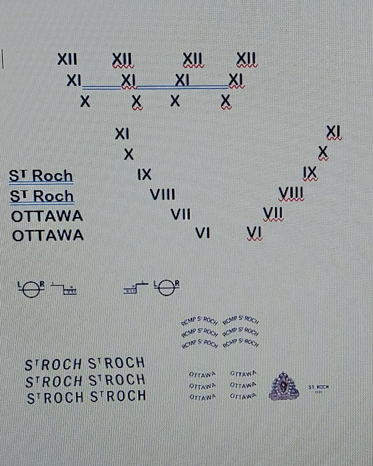
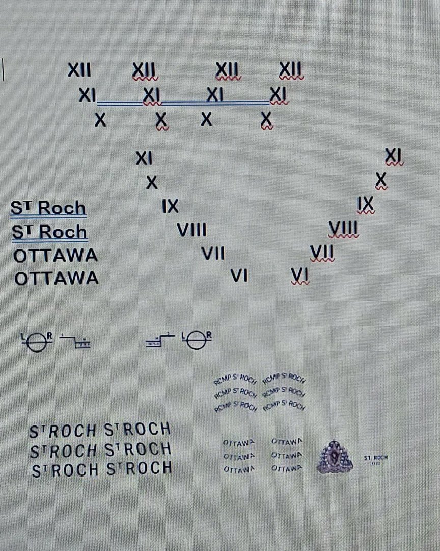
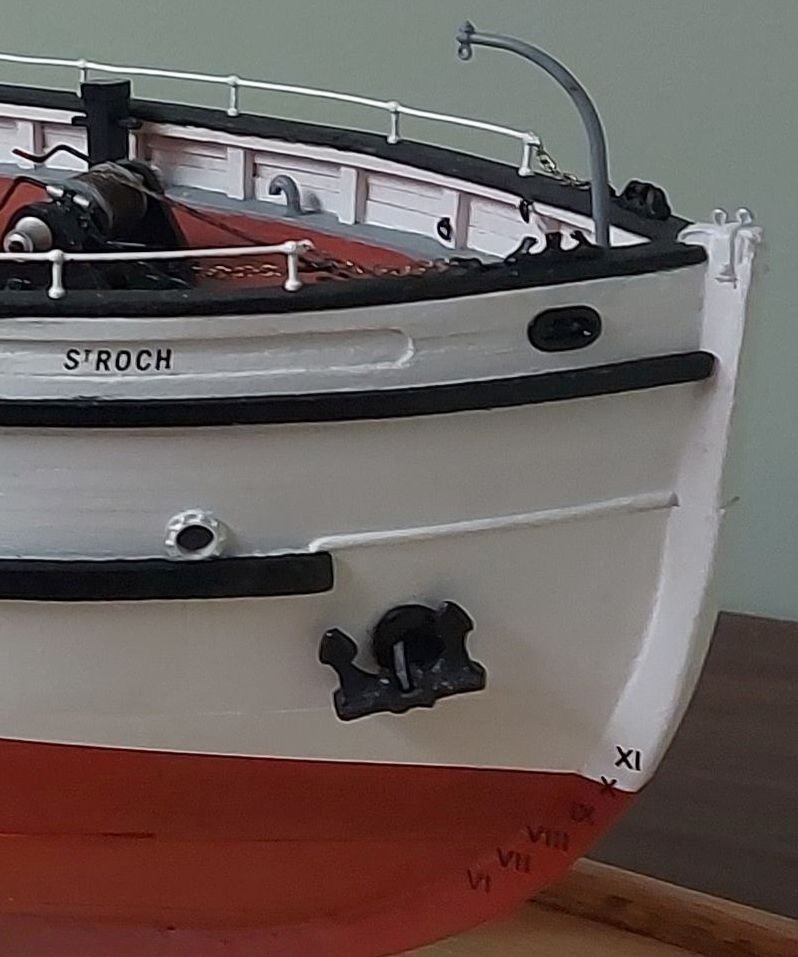
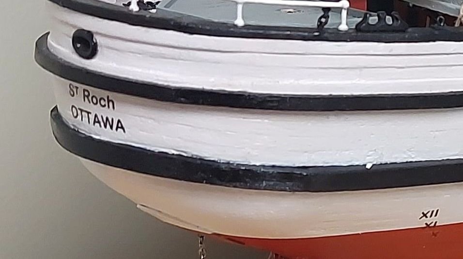
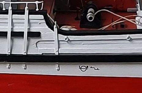
I printed off the decal sheet on my laser jet... this picture is from the Word file, that was created after photoshopping images to create the correct patterns. I forgot to take a picture of the actual decal sheet before I cut it up! For those interested, once the paper comes off the laser jet the inks are fixed with Microscale decal solution. I used my airbrush, first a light mist then a heavier coat. They say you can use a brush but the inks are fragile and I did not want to risk smearing the decals. I applied a coat of Future to St. Roch's hull, again with the airbrush. Decals seat better on a gloss finish, and mine snugged down nicely with Micro Set and Micro Sol. After the decals were applied I was going to use Tamiya acrylic matt finish to seal them in, however I rather like the semi gloss finish of the Future, so I used another application of that to seal them onto the model. The load line decals were taken from the original shape on the ship today, which included the "WNA" line. This was not used on St. Roch in the 1930s because there was no intention of sailing her in that ocean. Winter North Atlantic was added in 1942 when it was decided she would try for the North West Passage. The life ring legend was also taken from a modern photo, but in the 1930s the word "Ottawa" was not used, so I left that off.

-
Thanks Kurt... I am musing about doing that with my no-sew, which has become my go to adhesive for anything textile related. Your suggestion affirms my thoughts and I will try this when I get back to it after the weekend! Regards, Bruce
-
I will definitely be paying more attention as I move onto the running rigging... my standing rigging is Amati and fuzz free. Although all four falls came from the same coil of line only that one has a fuzz problem...
-
Yes, but in this case the falls would be hanging outboard, and what pictures I have do not show this configuration on St. Roch...
-
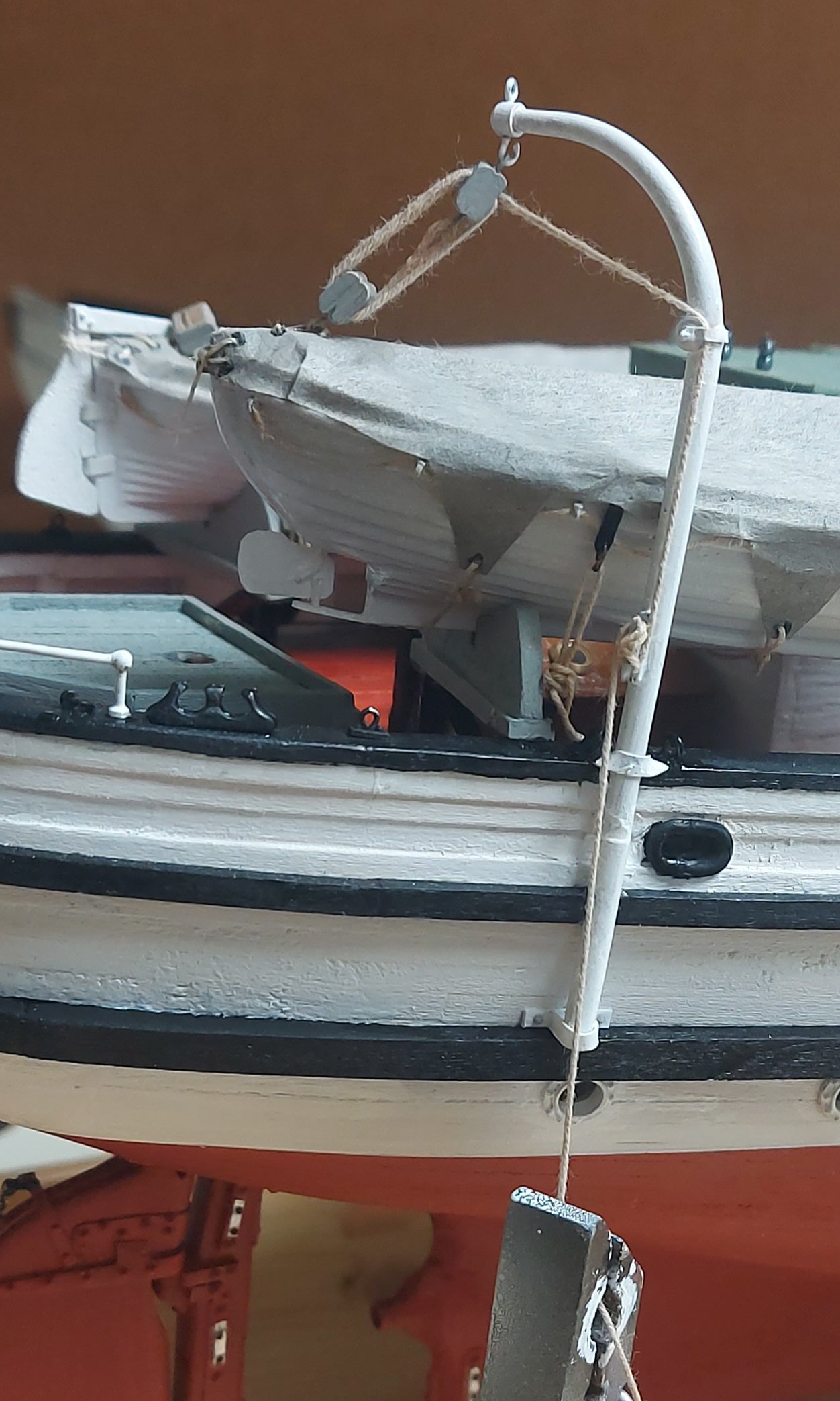
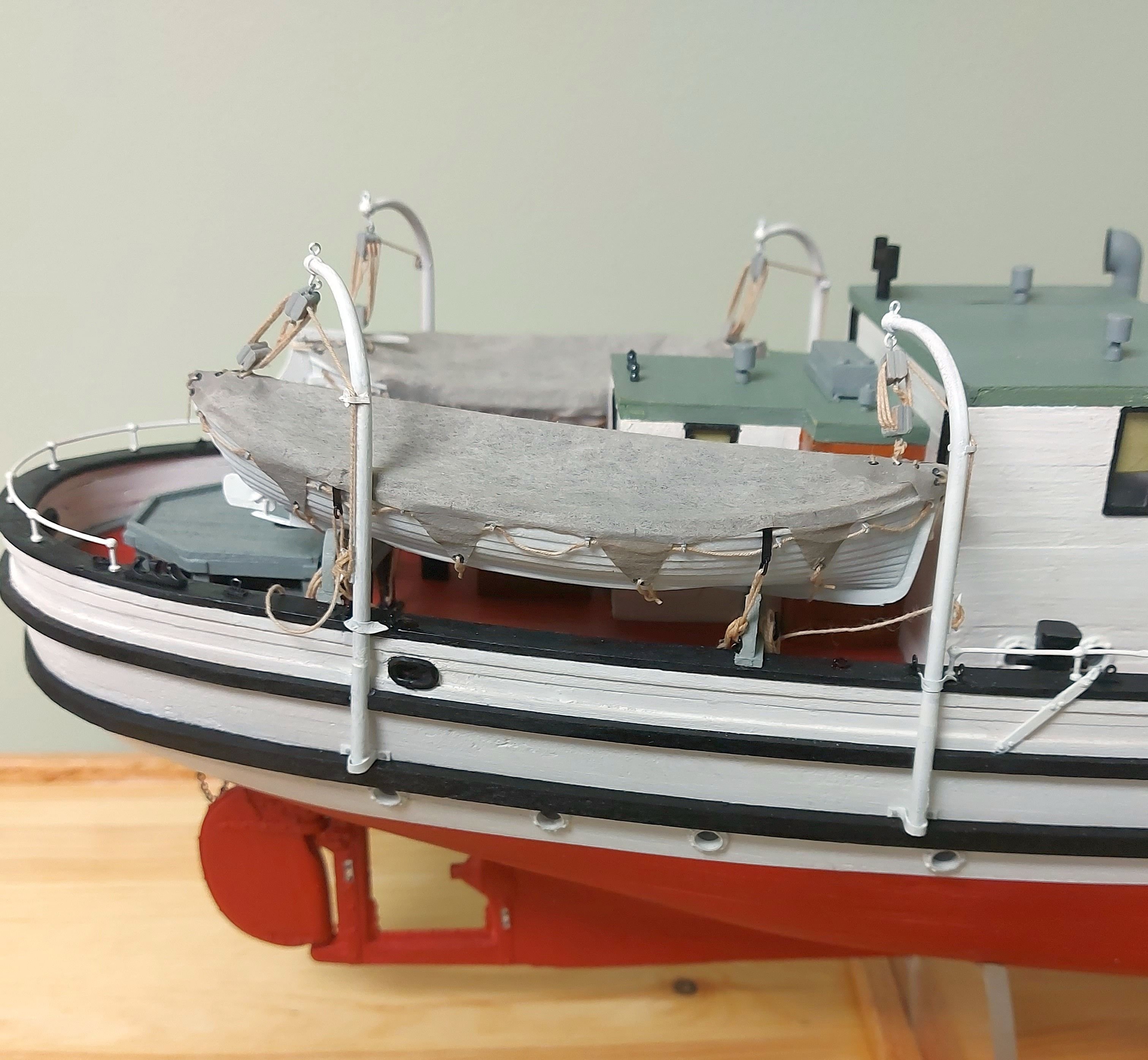
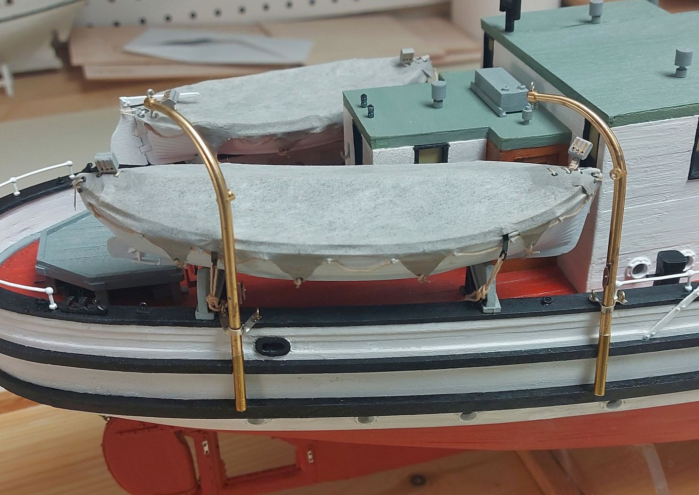
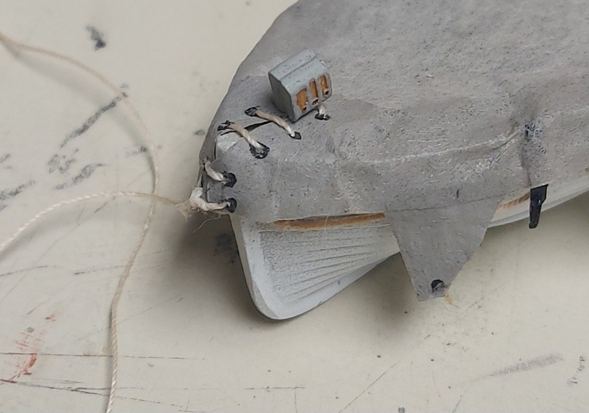
I had to take a couple of days and work off the outdoor fall "honey-do" list, however the davits are painted, mounted on the ship, and rigged. Here is the aft motorboat davit, the clothespin maintains tension while the 'No-Sew' sets up on the cleat... I have no clear photos of the bottom davit bracket, so I made a fitting that is functional and conforms to what I can see on pictures... I see some fuzz on the line, not sure how I'm going to deal with this since it will be very difficult to replace the line at this point. Any Suggestions?? Here is the motorboat secured to the falls and lashed down to the cradles. I added a pin to each cradle on which to hang the falls. This seemed to be the best arrangement given the close quarters and absence of pin rails. And here is the dinghy... Sailors can handle the lines without leaning outboard... The poop deck is very tight with the boats installed, so although the spare rudder can still fit under the cradles, I don't think it is practical to stow it there because it would be very difficult to handle it. I am thinking good thoughts about stowing it in the waist like it is on St. Roch today...?? This evening I will print the decals, but there is a three day relative riot happening because this is the Canadian Thanksgiving weekend, so I won't get them on until next week. Once the decals are on the hull will finally be complete and I can move on to the masts and standing rigging! Thanks for looking in, and any suggestions and comments are always appreciated. Happy Canadian Turkey Day, Bruce


- 368 replies
-
- 14
-
-
Thanks Yves. I wish I could take total credit, but the davits started off as Caldercraft items that I modified! Regards, Bruce
-
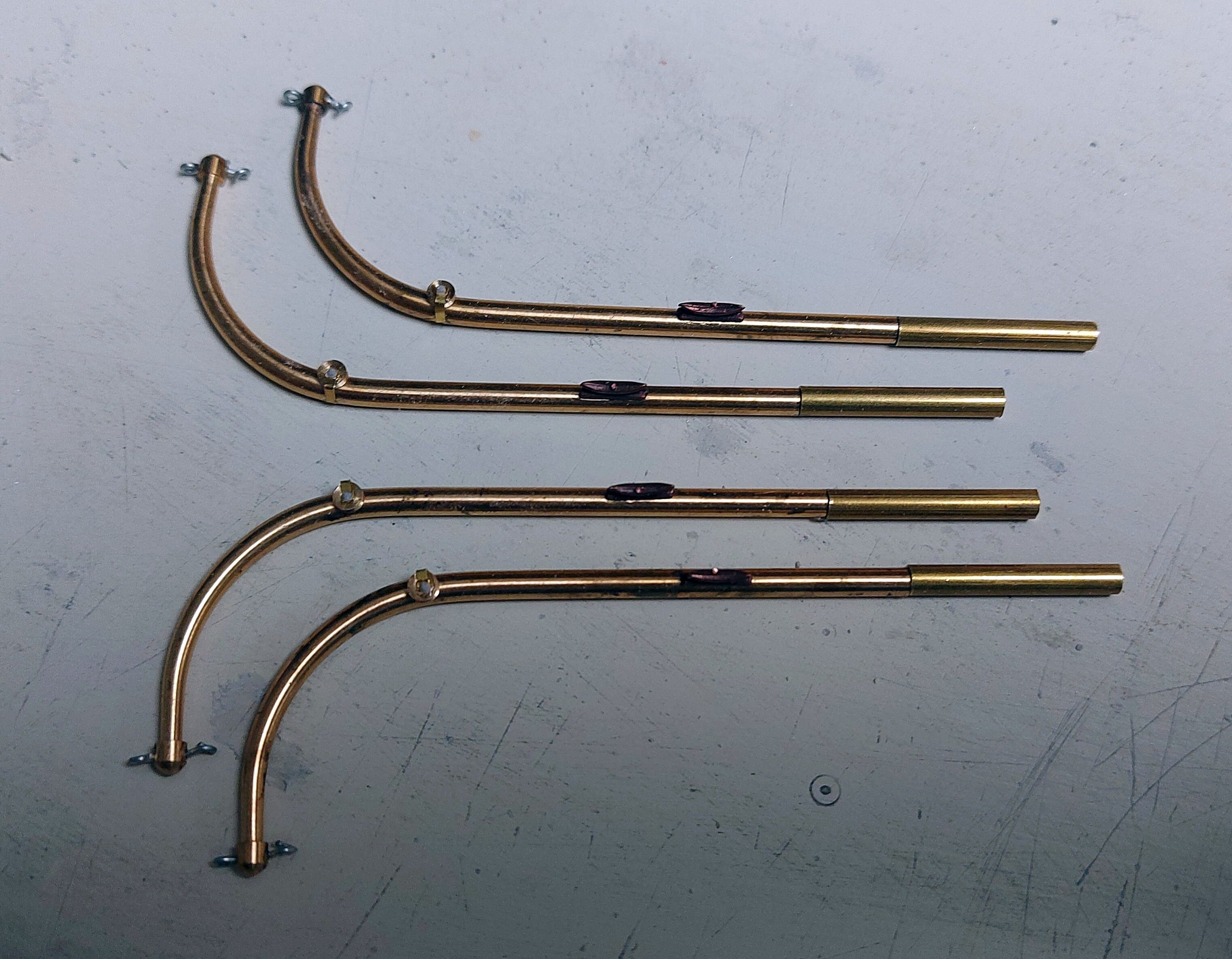
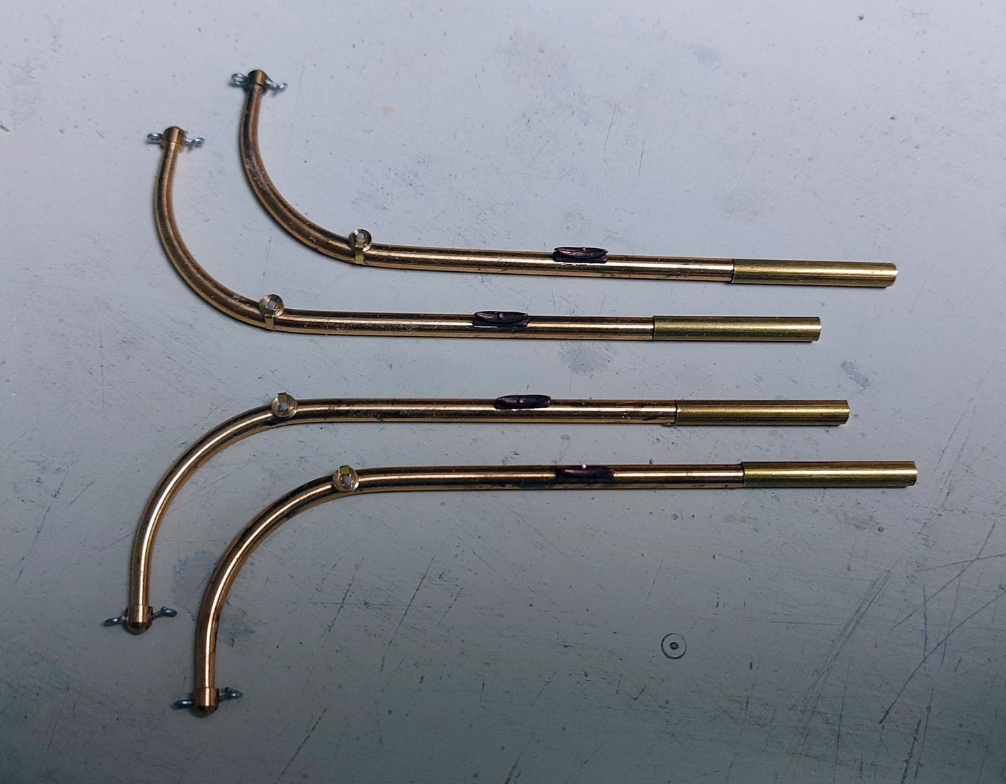
I have finished fabricating the davits... I added keepers to each pulley so the falls won't slip off. I extended the shafts to the correct length for St. Roch, based on photos. I also opened the eyelet at the tip that will receive the upper block for the falls, this should make it easier to do the final assembly... The davits mount outboard, and period photos show they rest on the rub rail and fasten there as well as to the cap rail. The latter, from plans and photos, appears to be a strap that is wrapped around the davit and then bolted flat to the cap. I have replicated this using scrap brass from old photo-etch frets. The davits are also placed relative to the lower deck portholes based on photos. In the picture I am trial fitting the motorboat davits to the cap rail. I still have to make the base mounts and then it is off to the paint booth. I have also decided, in the absence of definitive evidence, to hang the falls' coils on pins that I will install onto the cradles. This keeps these lines handy, and more importantly, inboard! As always, comments and suggestions are welcome!
- 368 replies
-
- 14
-
-
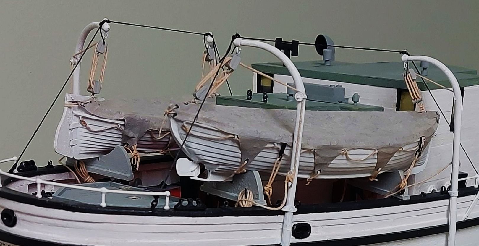
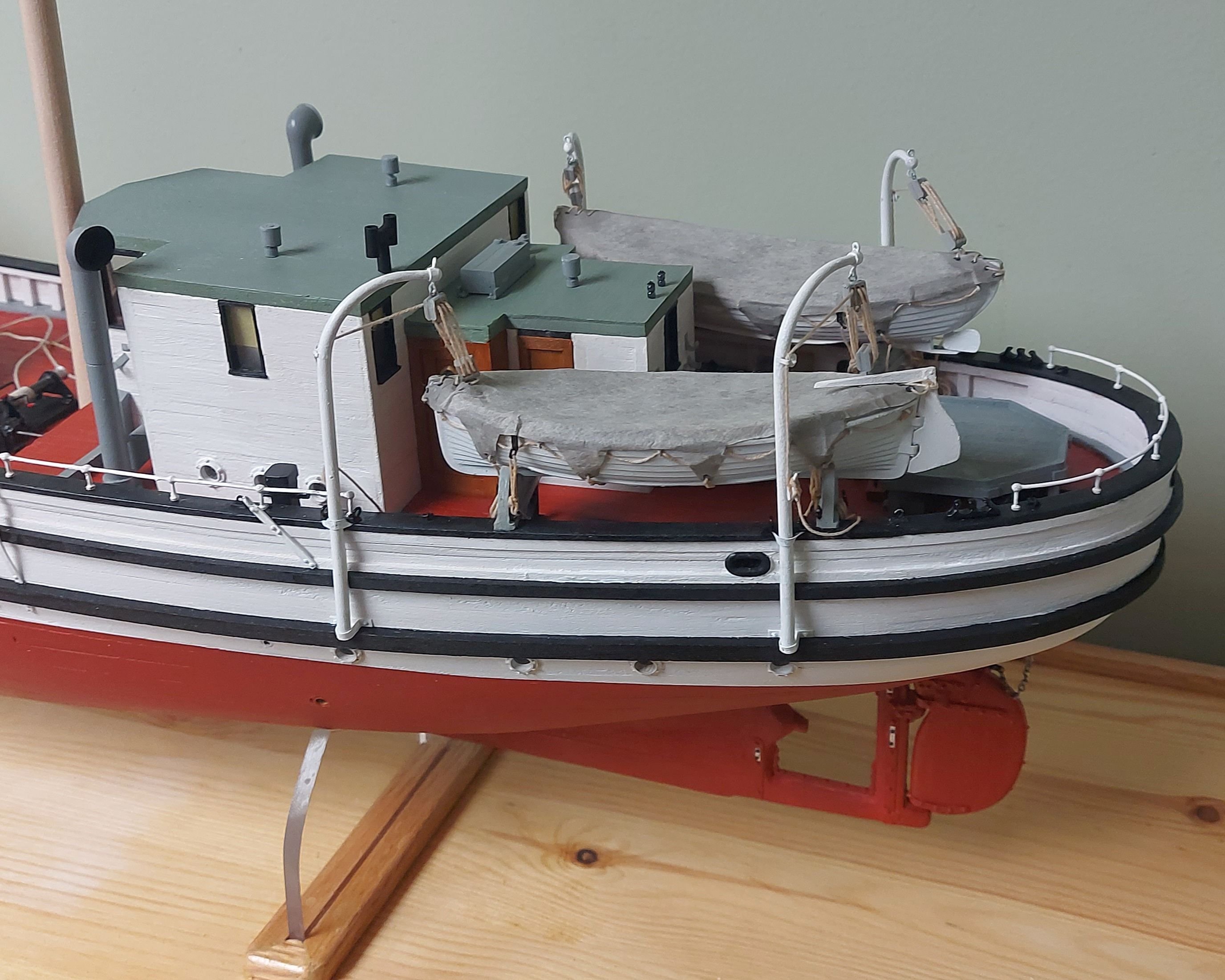
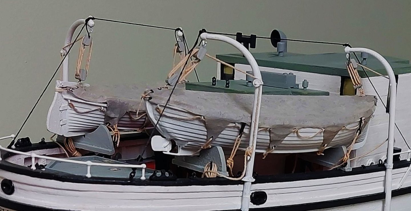
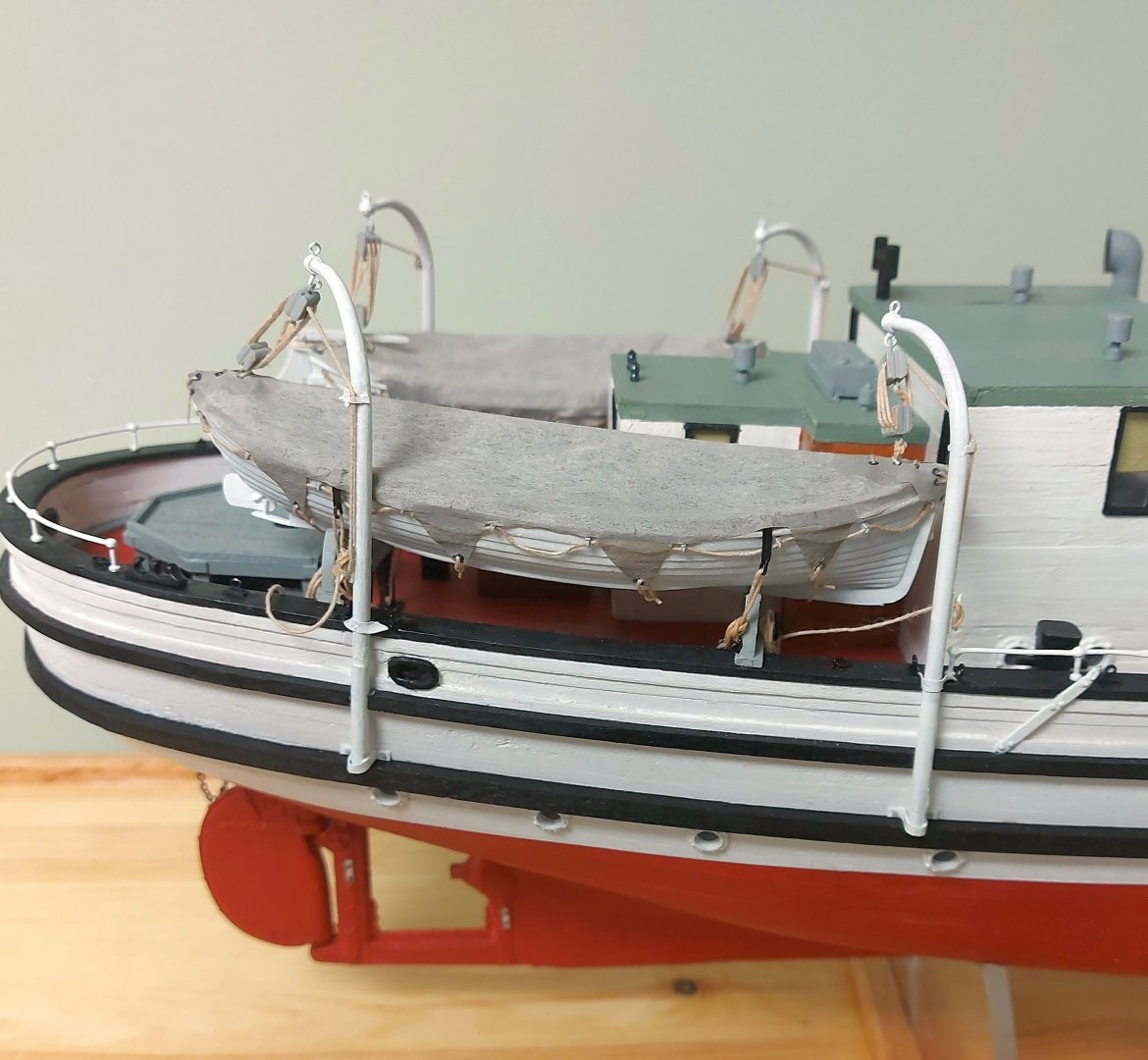
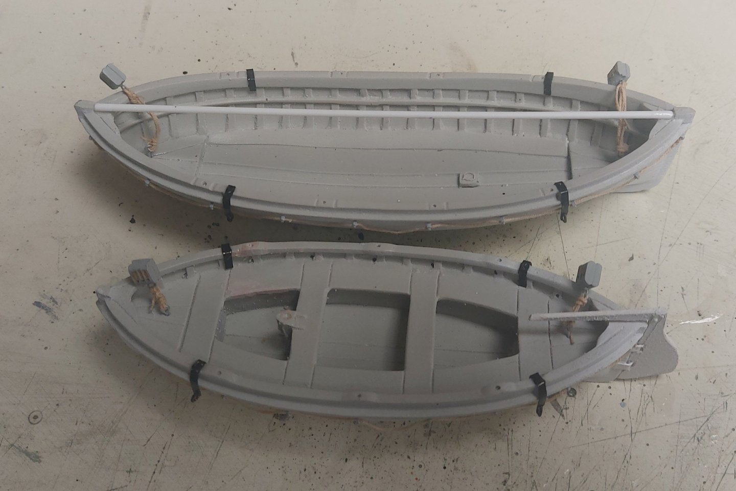
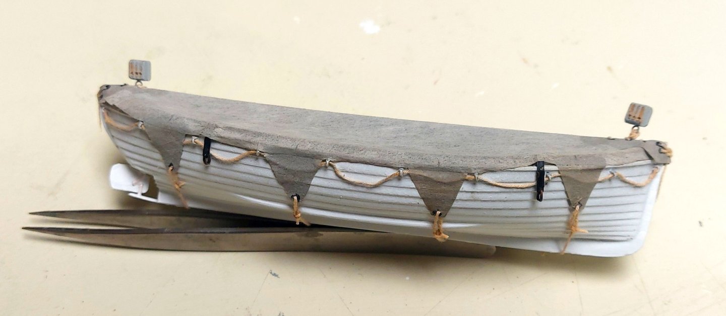
I said earlier that the next time I showed the ship's boats they would be installed on St. Roch; and here they are! First I lashed the lower fall blocks to eyes in each boat... Then when I went to install the boat covers, some of the holes tore, so I had to digress a little bit and fit doublers of silkspan wherever there were grommet holes... After trimming the doublers I could begin to lash down each cover, using bowlines at each of the 'darn cat ears'... this picture shows the motorboat cover lashing started, and the upper falls with their eye splices... Next up are the bow and stern lashings on the dinghy cover... And the motorboat cover complete. Keen eyes will see I have installed the boat's rudder and am waiting for the prop... And finally here are the boats all lashed down and secured to their cradles! I can't put it off any longer... I have to finish the davits! Thanks for looking in, and as always comments and critiques are welcome! Regard, Bruce


- 368 replies
-
- 16
-
-

-
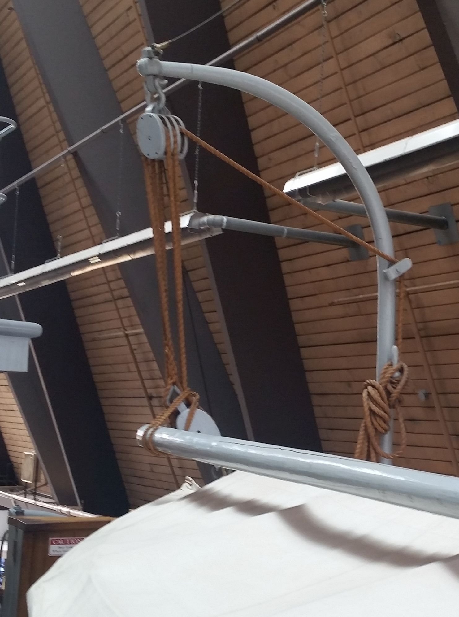
Things are coming along... I made the triple blocks, a scale 9", from a walnut strip. These will be used to rig the falls for the boats. I added cast brass eyebolts that will connect the blocks to the davits, and lash them to the eyes under the boat covers. The davits started out as Caldercraft items, they have the correct shape and taper. I removed the Caldercraft parts from the davits and added my own eyepins and cleats for accuracy. The cleats are held to the davit with a wire pin for strength. One davit is laid out with the blocks spaced as they will be once rigged. I still need to add a pulley guide, then make the davits longer to correctly fit the model. Then it will be off to the paint booth and assembly. The blocks on St Roch are metal clad... I will try and round mine a bit more without breaking anything, we'll see how that goes! I will paint them grey except for the sheaves. The next picture shows one of the motorboat davits on St Roch. The picture shows griping spars, but period photos do not show them, so I will be leaving them off the model. Period pictures also do not show the falls coiled onto the davit cleat... not sure where they were hung so I'll have to do some thinking on that. Getting closer to adding more fiddly bits to complete the hull! Bruce


- 368 replies
-
- 12
-
-
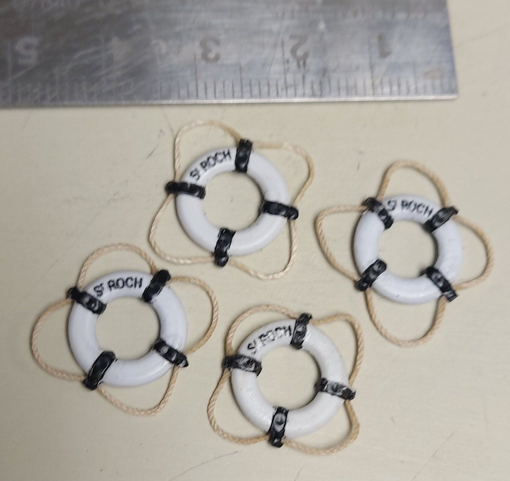
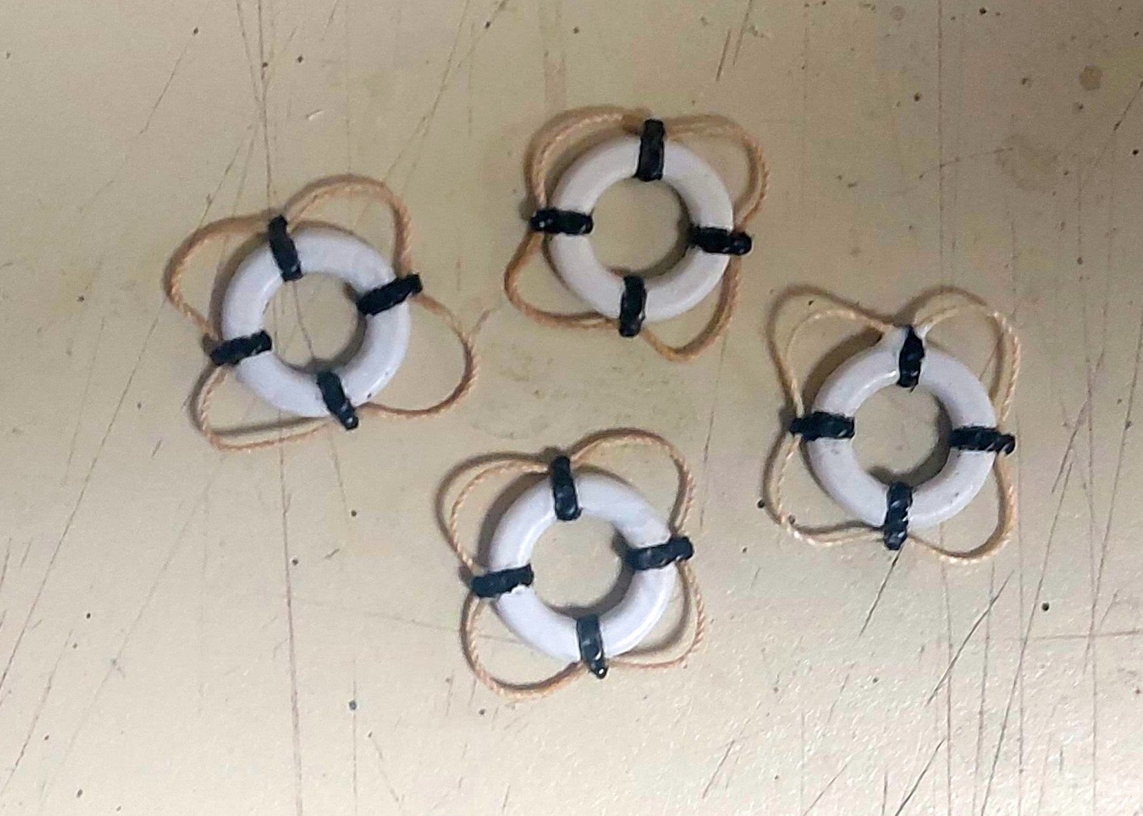
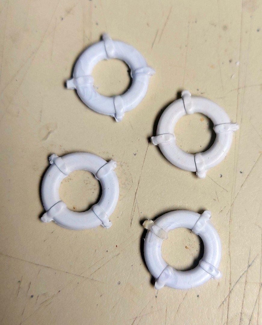
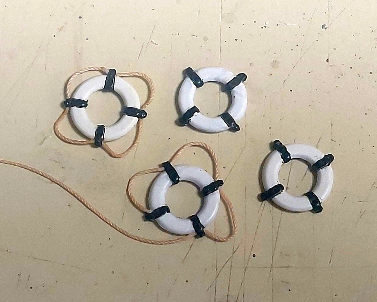
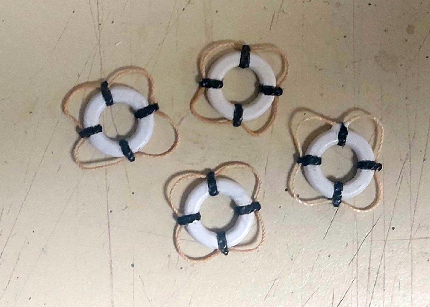
For some strange reason I keep holding off on the boat davits... probably because I know I will knock them off the model more than once unless they are last to go on! With that in mind I made the life rings next, St. Roch mounted four around her deck house. I started with plastic rings from New Cap Maquettes. They are the right size and cross section, but they come with plastic lines molded on around the ring. These were the first things I cut off, resulting in the picture below: Next I trimmed up the molded seam lines, and painted the rope rings black. Then I used my miniature drill to make holes through the rope rings, and began stringing hemp lines around the perimeters. Here are the four rings complete and looking much better than when I started... Again I used 'No Sew' at each rope ring to hold the line. It dries clear and flexible, and will allow me to make minor adjustments to the ropes once it has set up. Next I need to add the name decal to each life ring, and make the brackets that mount on the ship to hold the rings...
- 368 replies
-
- 12
-
-
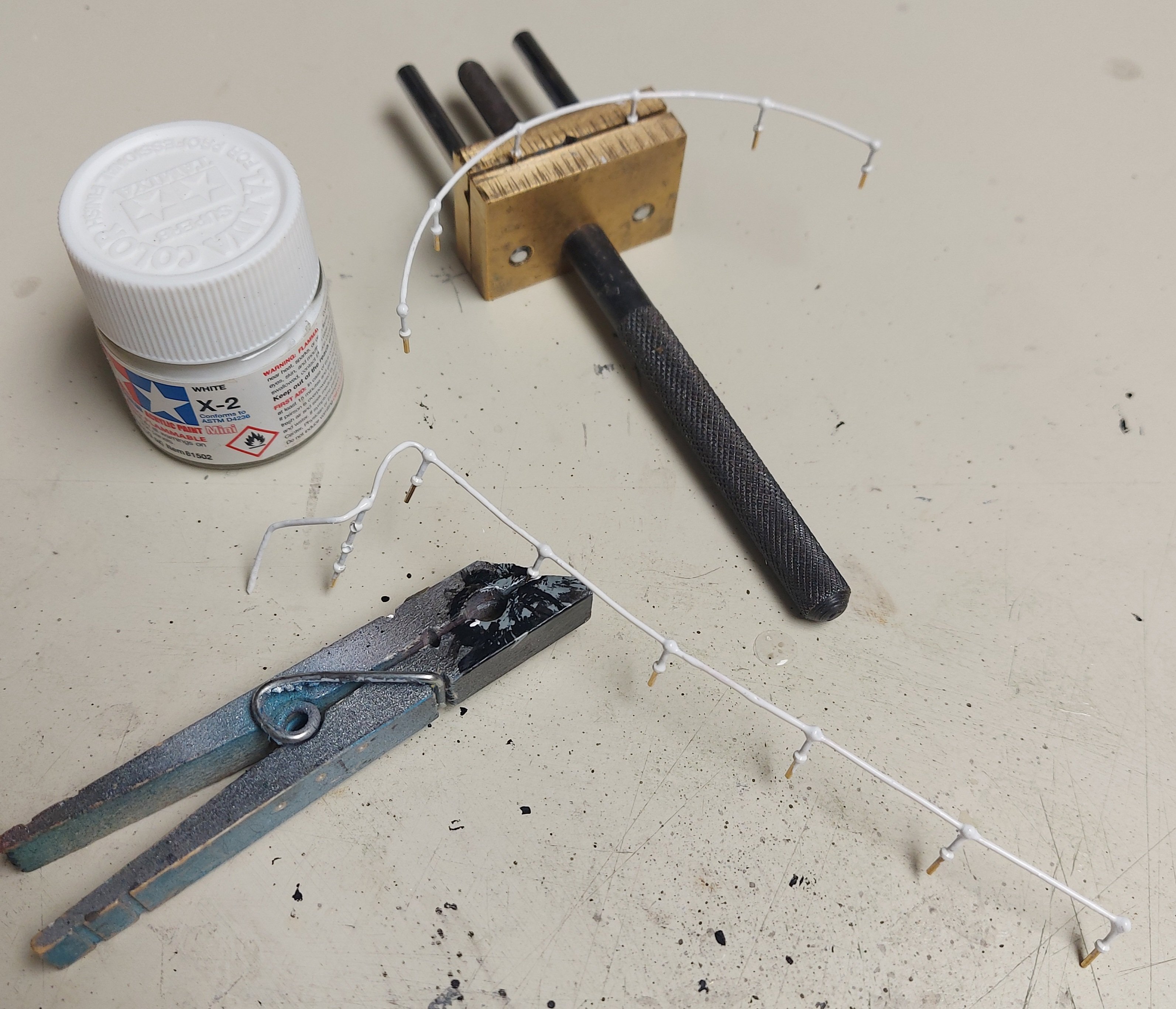
And here they are done, didn't take much time at all. The first picture shows the shaped rails off the ship for painting. I never try painting anything so fussy on the ship where the paint will get everywhere it shouldn't! After painting they popped right back into their holes... Et Voila! Done! Getting into the last of the hull details now. Davits and life rings to come, then lastly the decals! I'm starting the masts by marking the various locations for the bands and other fittings... stay tuned for more fun and games! Regards, Bruce


- 368 replies
-
- 12
-
-
Nice idea Keith, I will consider it for next time. Usually I run the railings by the airbrush, but there weren't that many so I brushed it on...
-
In between fussing with davit blocks I made good progress on the poop deck railings... The port rail is painted and installed, the starboard and stern rails so the CA can set up and fix the assembly. Then they will come off the ship for painting... Lots of fun! Thanks for looking in! Bruce


- 368 replies
-
- 10
-
-
-
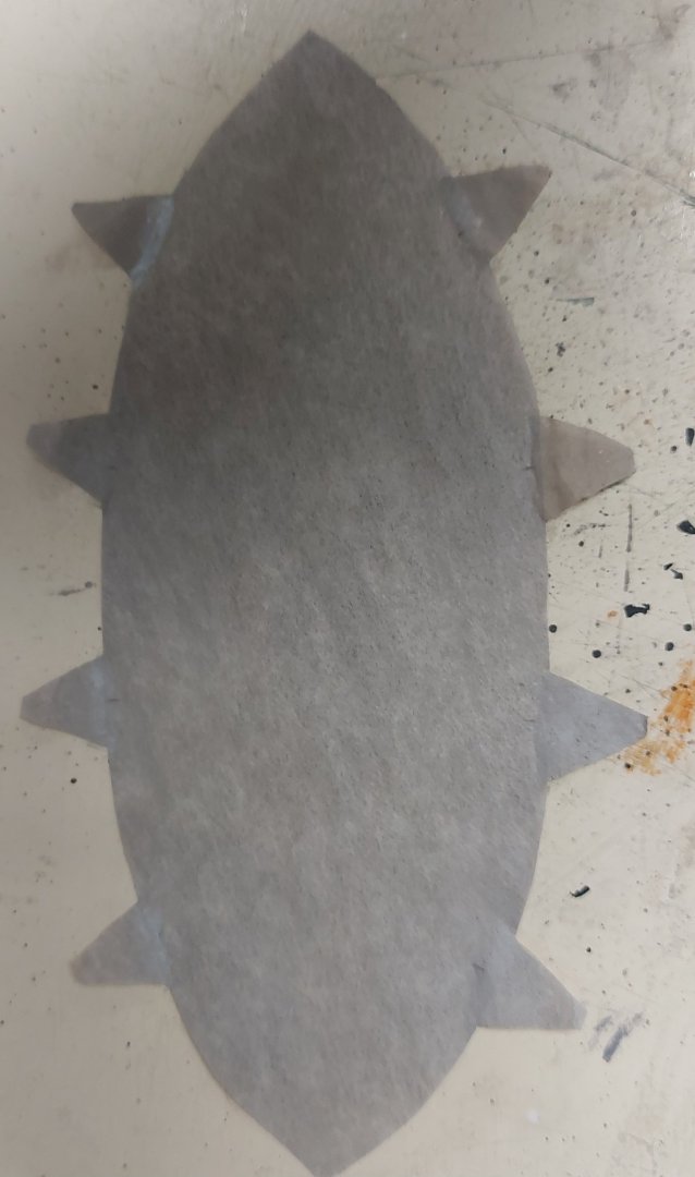
Progress on the boat covers... the No Sew worked a treat, and bonded the 'darn cat ears' very well to the cover... I moved on to drill the grommet holes, and like David Antscherl said the holes drill cleanly in the painted silkspan. I used a tapered cocktail toothpick dipped in Tamiya XF-18 Semi-gloss Black to paint the grommets. Just dip the pointy end into the paint then into the grommet hole, it leaves a neat painted circle. After that I prepared the motorboat by gluing a spar bow to stern to 'tent' the cover like the original, and also glued the gripes in place. The picture shows the boat and cover to this point. Next I centered the cover over the boat and used a water soaked paint brush to wet it, enough to start getting a tent shape and fold around the edges, and the 'darn cat ears' stayed on, Yay! I left it at this point to dry, I will give it another wetting before lashing the cover to the boat. First I have to lash the triple blocks to the eyebolts in the boat, these will be the lower part of the falls. Almost made a mistake when I forgot to make sure the 'darn cat ears' would not interfere with the gripes, but fortunately there were no conflicts! So far so good, so I made a start on the dinghy. Since it is done the same as the motorboat I won't repeat the details in this log. Next time you see the boats they should be in their chocks with everything lashed down!
- 368 replies
-
- 11
-
-
-
Thanks Bill, your boat cover looks great! nice idea about gluing a strip around the edge, I'm hoping mine fold over when wetted without the triangular pieces falling off! Regards, Bruce
-
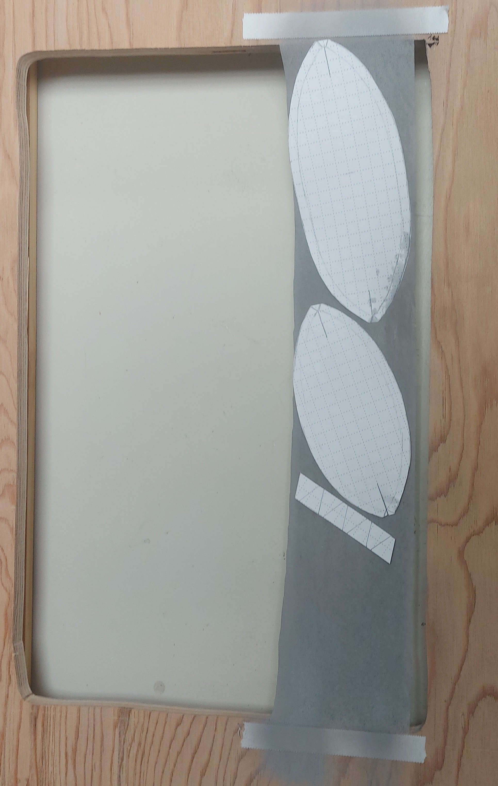
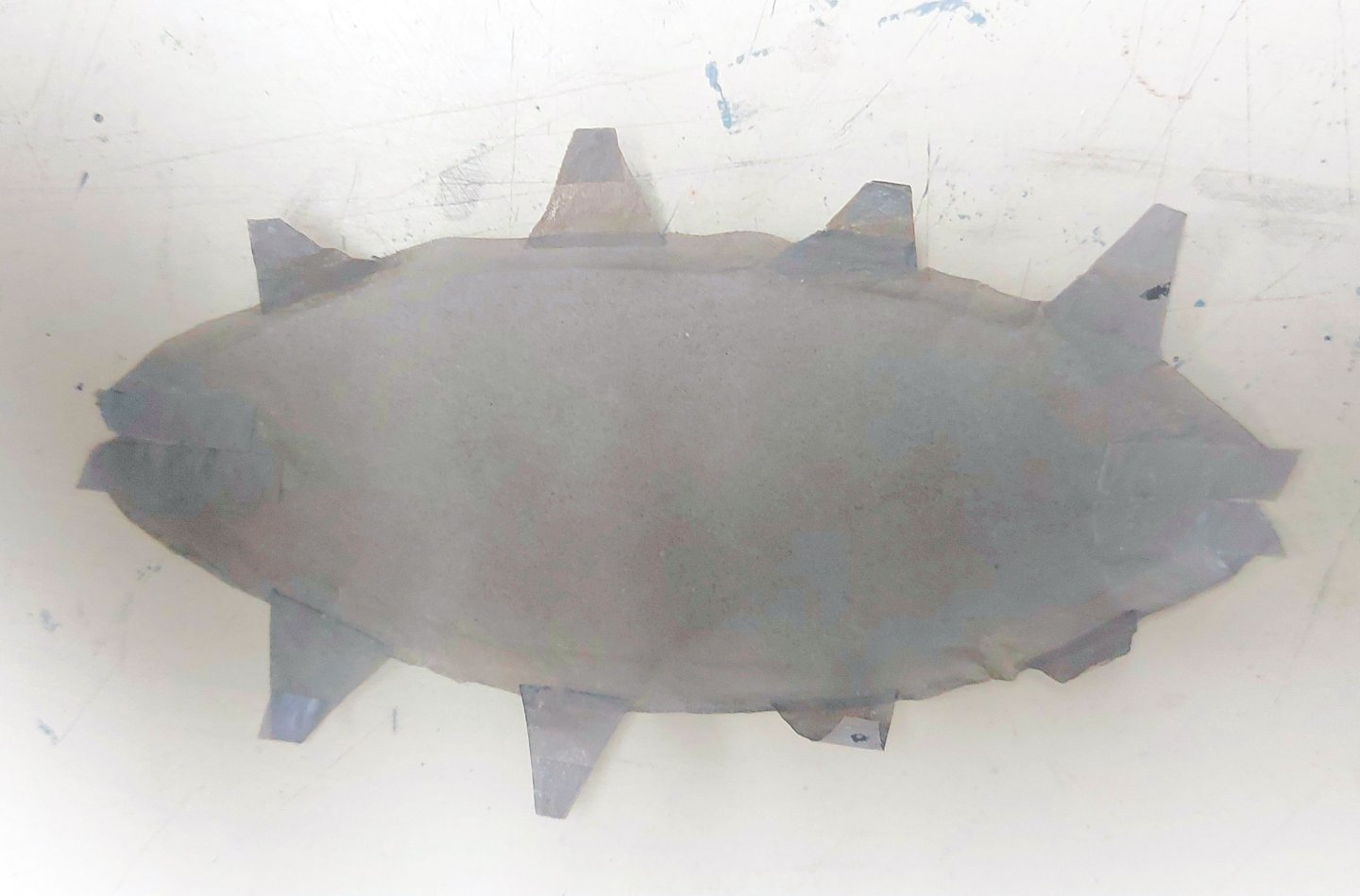
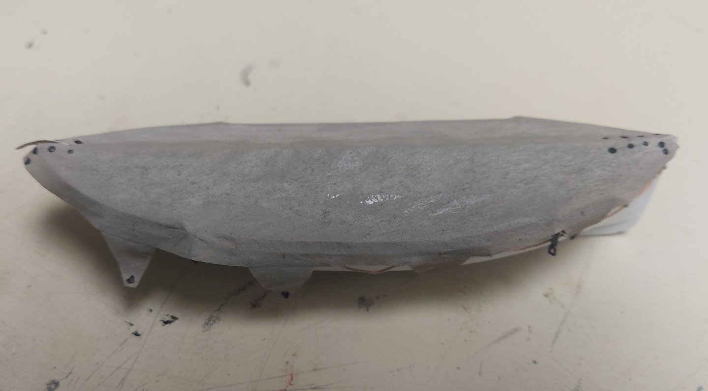
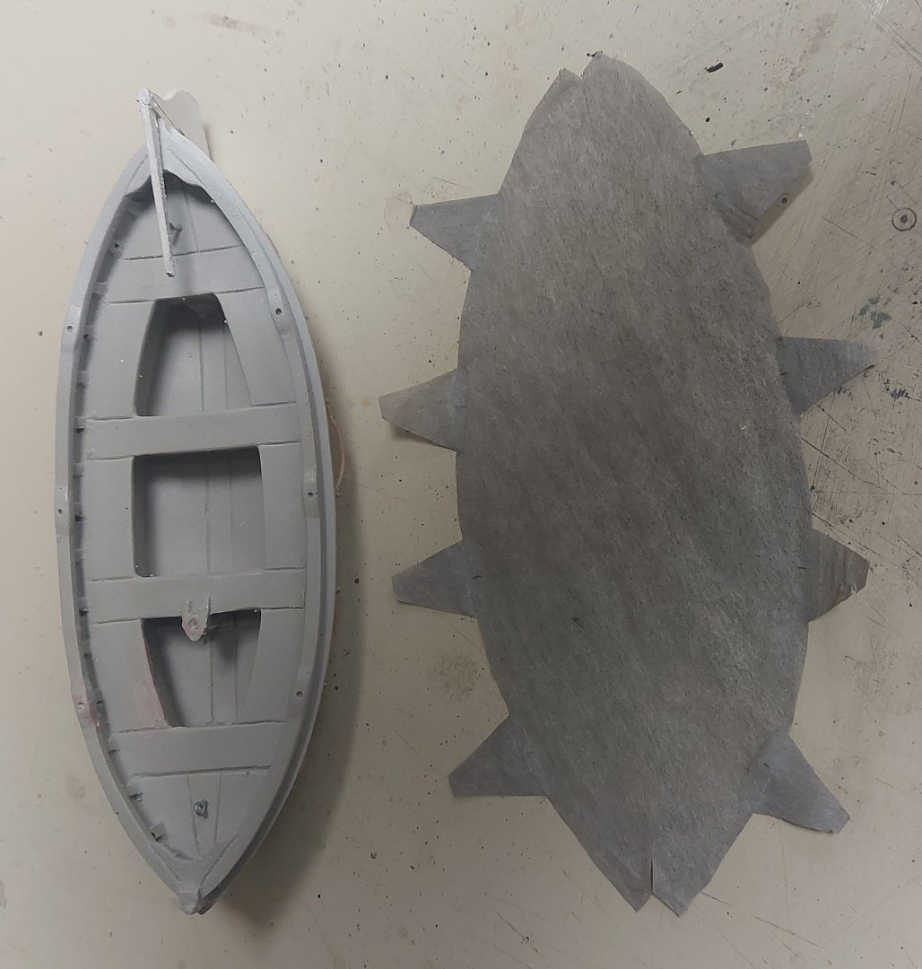
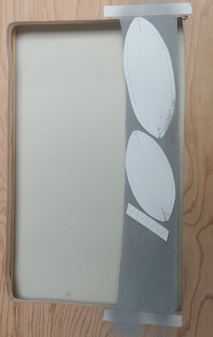
After some back and forth with the airbrush I am happy with this shade for the boat covers... the picture shows the paper template, the cover pieces cut from the silkspan, and the 20' motorboat... The triangular pieces are the tie downs (not sure if they have a nautical name or not?) They are just set in place to see how things look. David Antscherl recommends Matte Medium for gluing silkspan pieces together. I have lots of 'No Sew' on hand so I'm giving that a try. I have used it before with great success gluing flags to halliards and anything else involving fabrics. It dries clear and flexible, and once set up it can be washed, so it is waterproof. Here is the motorboat cover assembled, waiting for the No Sew to dry. We'll see how it holds together when I wet the cover to fit the boat, and when I lash it down... I'm going to give it a day and maybe a second application from the back side... delving into uncharted territory here!
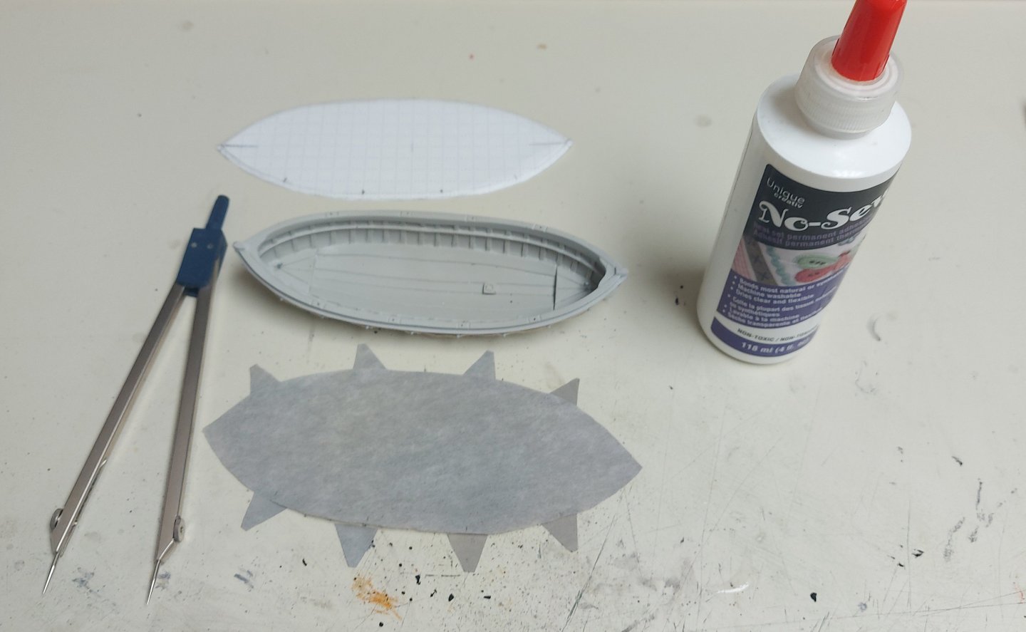
-
Our cruise was with Viking, Paris to Rouen and back including Giverny, the Bayeux Tapestry and Juno Beach. We arranged a private guided tour of the cathedral and absorbed a lot of knowledge about gothic architecture and the history of the building. The lines moved fairly quickly... Unfortunately we did not have time to visit La Musee de la Marine... or Honfleur... next time!
-
Hi Wefalck... we enjoyed our cruise on the Seine, and the restored Notre Dame is amazing! I agree about the colour choice and I will shoot a thin coat of flat white onto my boat covers. Pictures I have show St. Roch's boat covers sometimes light, sometimes darker... could be the lighting or camera settings with black & white film... Yes, her sails today are reproductions, but originally they were cotton canvas. I'm also thinking about a light gray, off-white, for the sails and we'll see how they turn out! I appreciate your feedback, Bruce
-
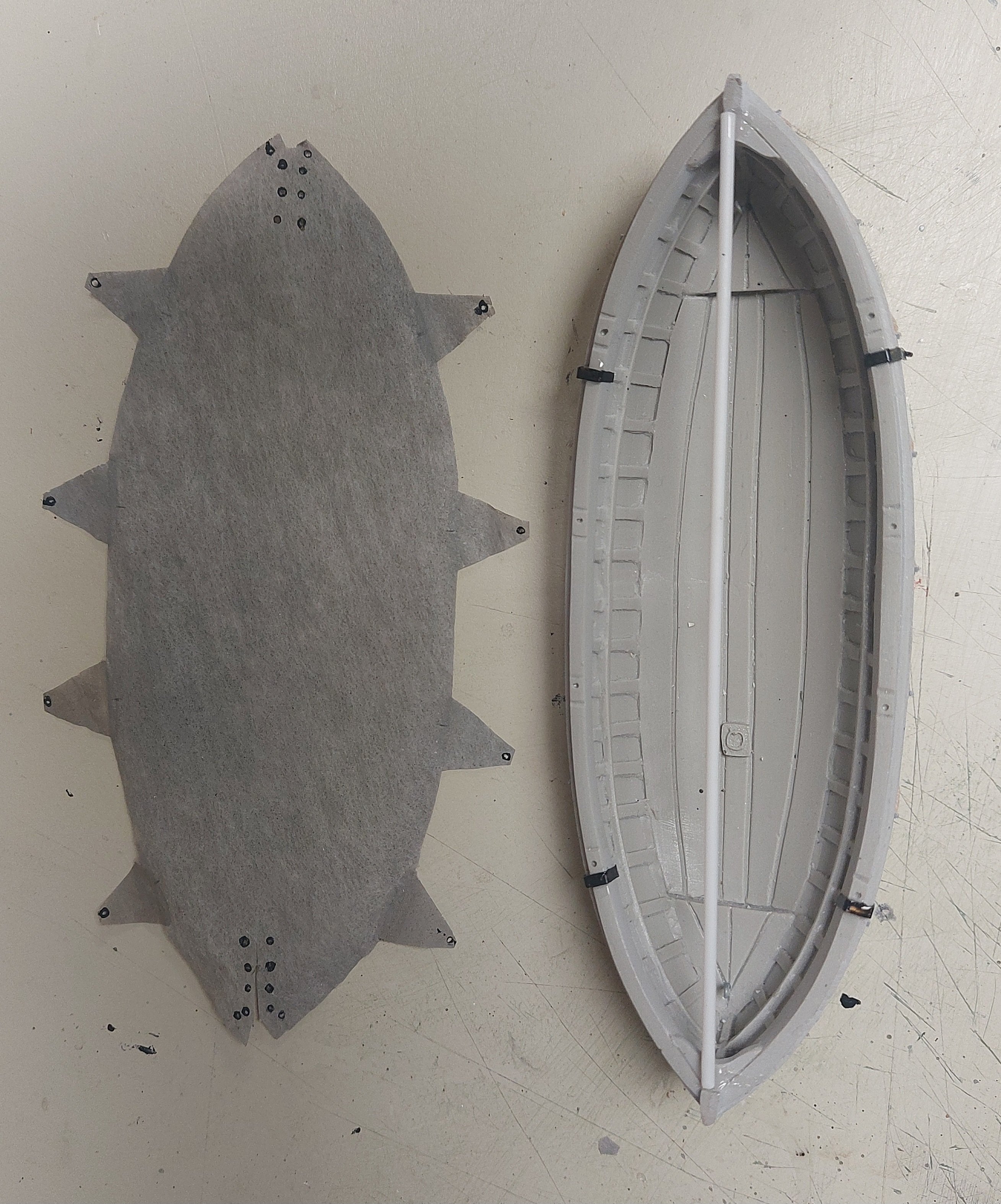
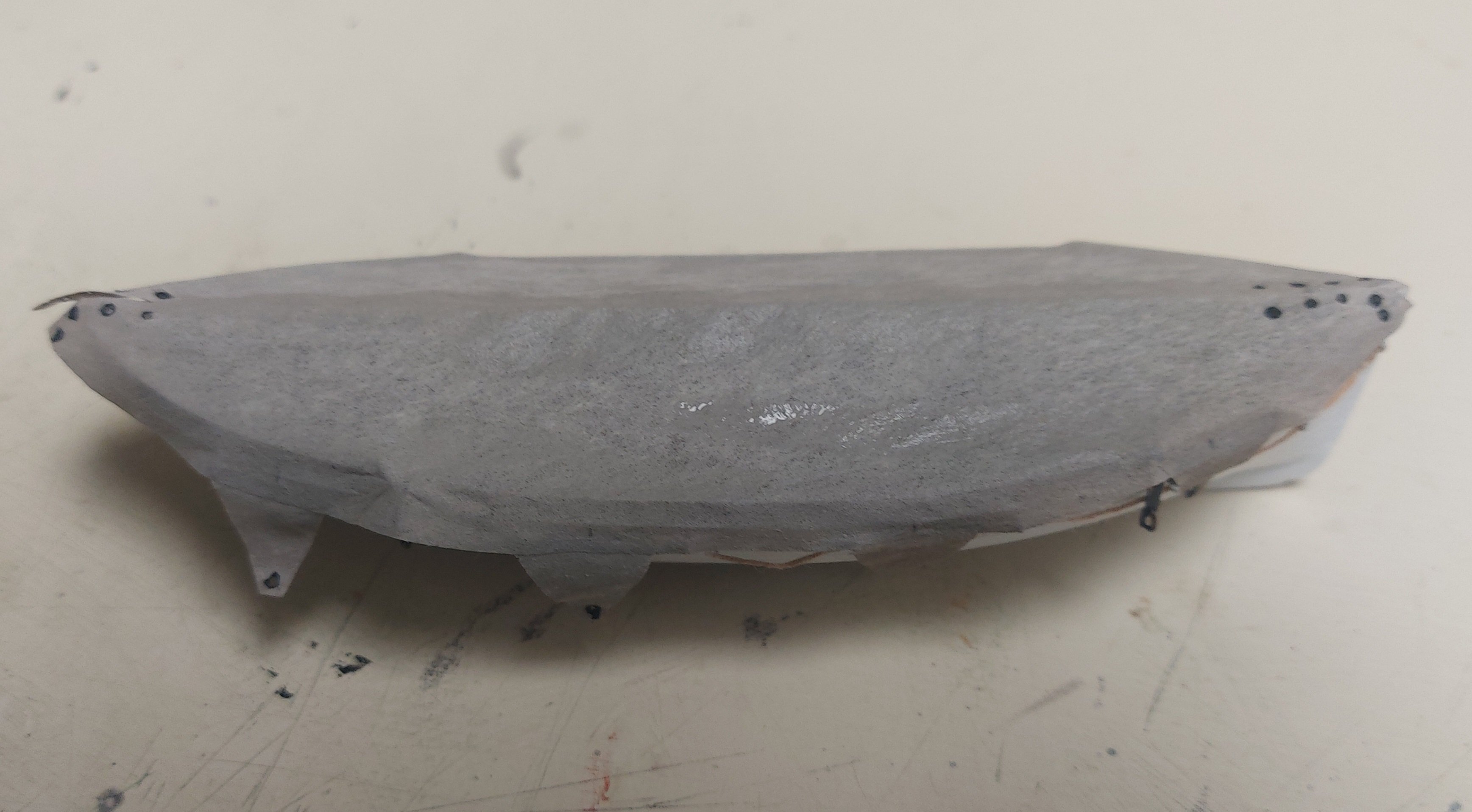
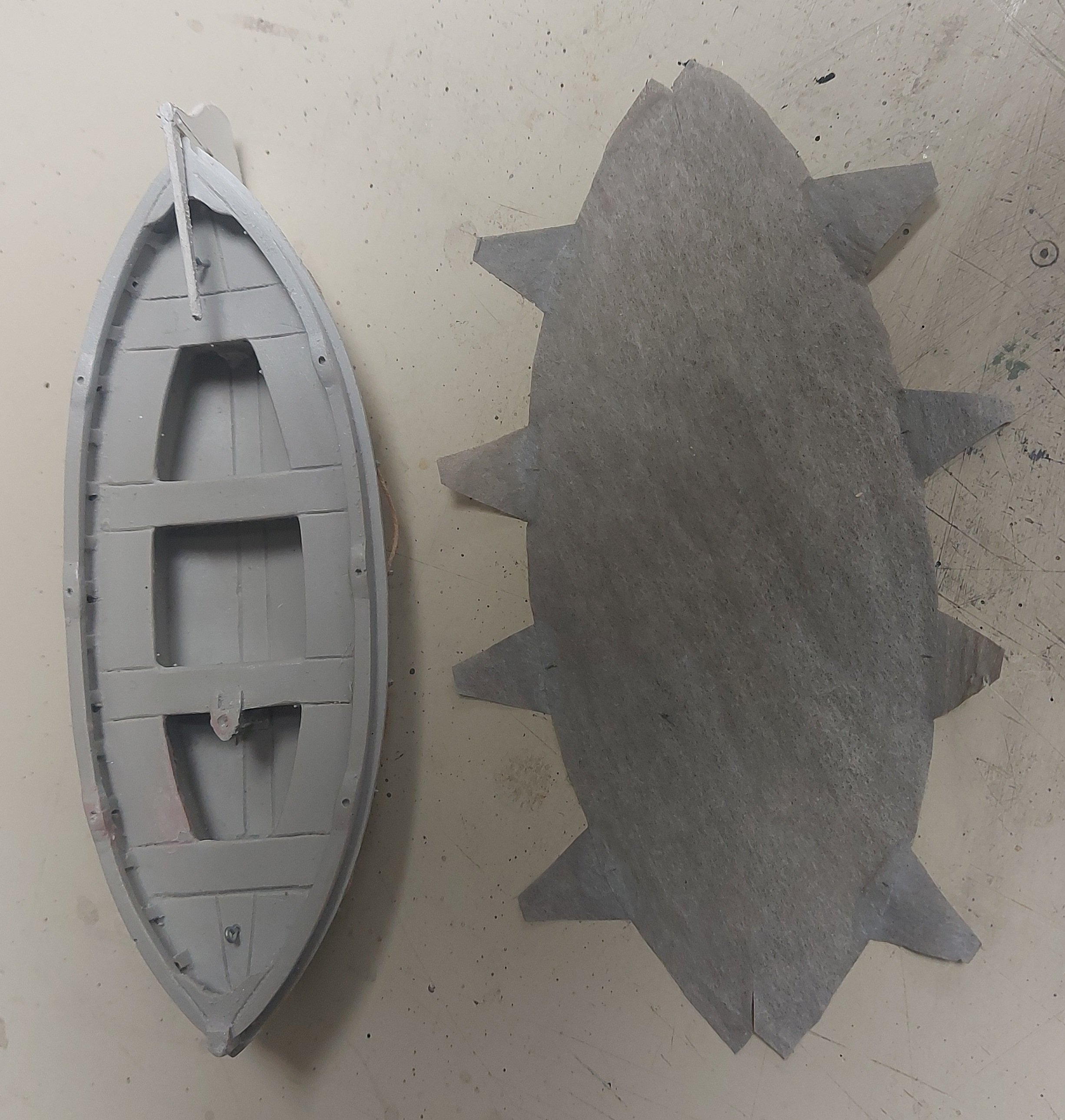
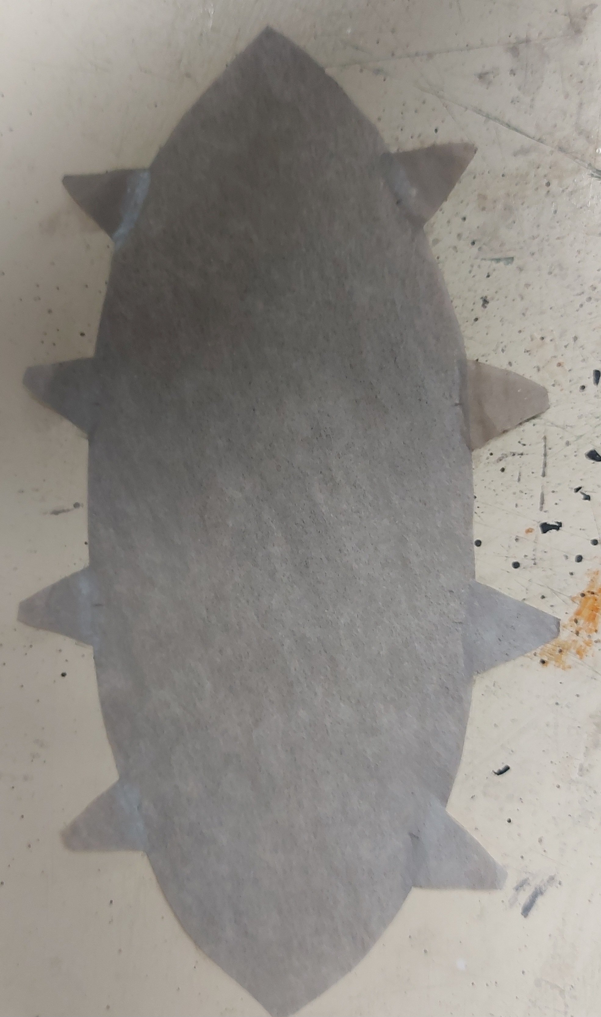
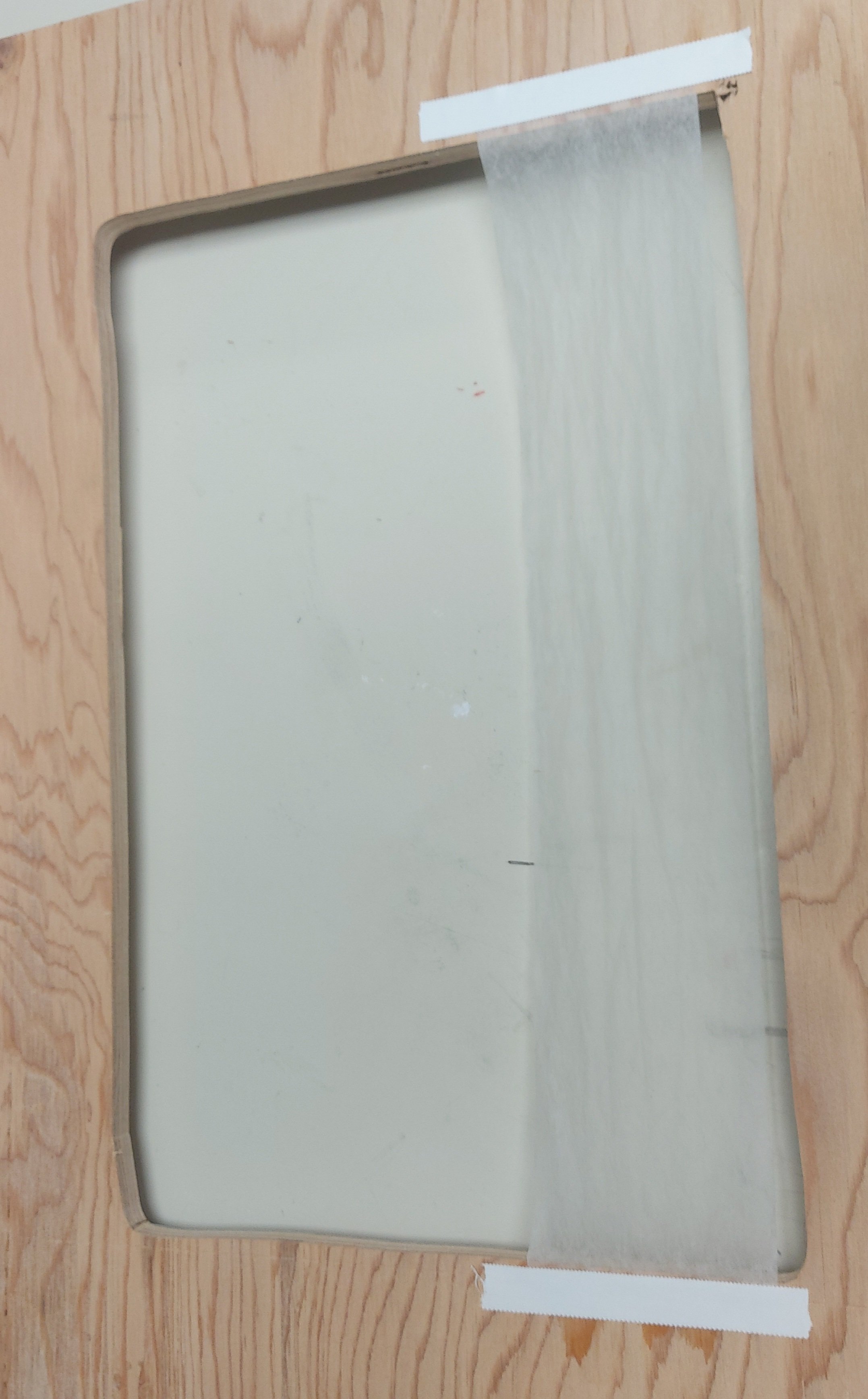
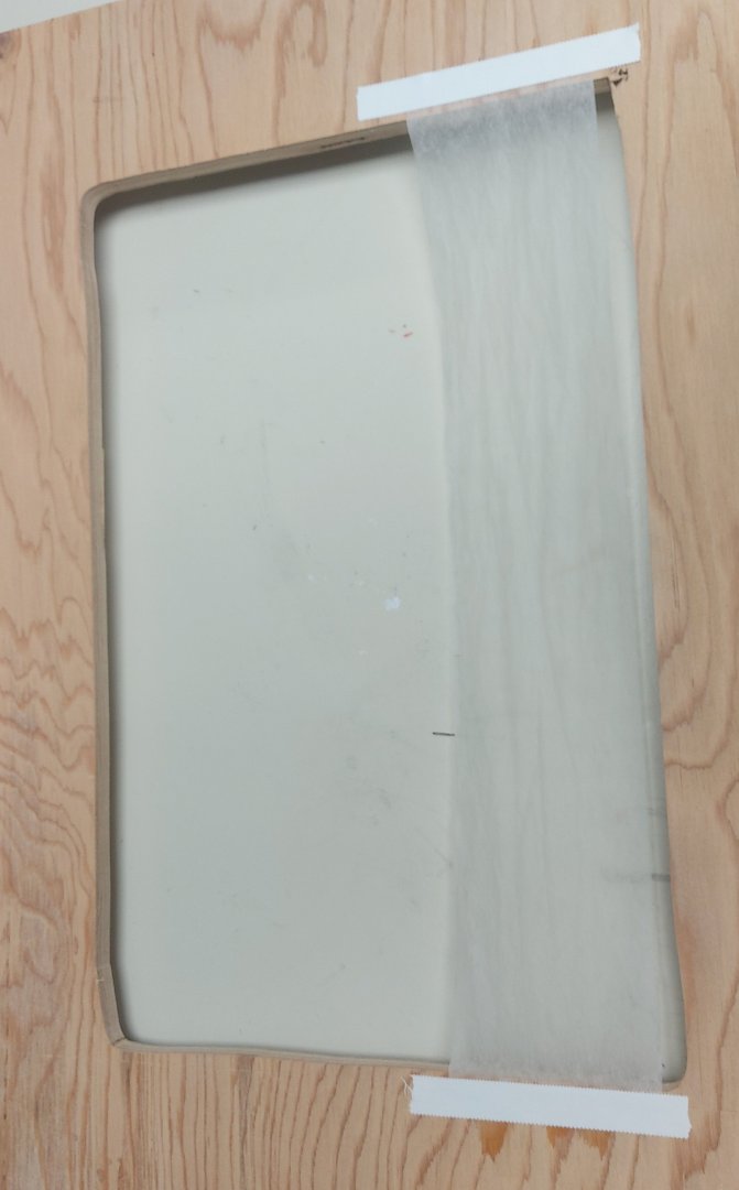
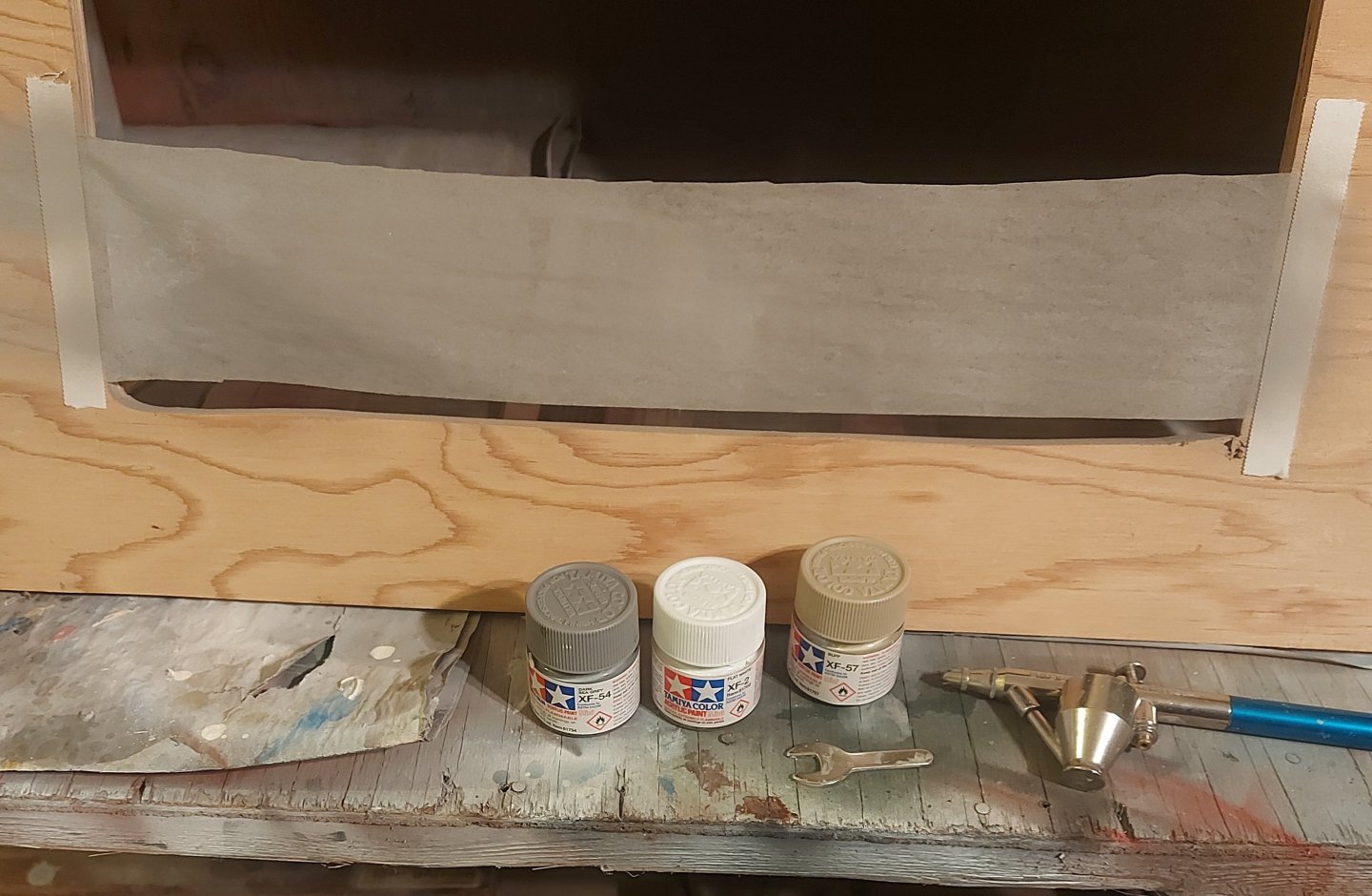
I'm back, and well rested! So back to the silkspan... I decided to first work with an offcut to make the boat covers. This leaves the main piece of silkspan for the sails, and if I mess up the offcut I can still make the sails (I hope)! I had previously (on page 8 of this build log) made the frame to hold the silkspan. Now I wetted the offcut and taped it onto the frame, per David Antscherl's directions. I deviated by using medical adhesive tape since I could not get the paper packing tape in Beaumont. It is waterproof and seems to work very well. Taping two sides vs. all four did not seem to matter on a piece this size. Here is the wet silkspan drying on the frame. Next I coloured the silkspan to match what I think the boat cover canvas would have looked like. Rather than the artist's tube paints recommended by David I chose to use my Tamiya acrylics. Buying tube paints would leave me enough left over that I could will them to my heirs! The Tamiya paints are water based and give me a broader range of colours, and would go on with my airbrush, which I considered a better technique than brushing. I used a base of flat white, and added a drop of buff and another of dark sea gray. My airbrush cup was about half full, so I topped it with Tamiya thinner and sprayed it onto the silkspan. Here it is in the spray booth. I laid down two coats, light enough that there were no runs. When I moved he frame to my bench I saw that the colour was more gray than I would have liked. Memo to self, better lighting at the paint booth! Here it is drying on the bench with the boat cover templates laid on top. After it dries, if I am still not satisfied, I'll shoot another coat of diluted buff to try and get more of a canvas colour... we'll see. Next will be to cut out and assemble the covers, then try to get them to fold nicely over the boats... Thanks for looking in, tips and critiques are always welcome!
- 368 replies
-
- 10
-
-
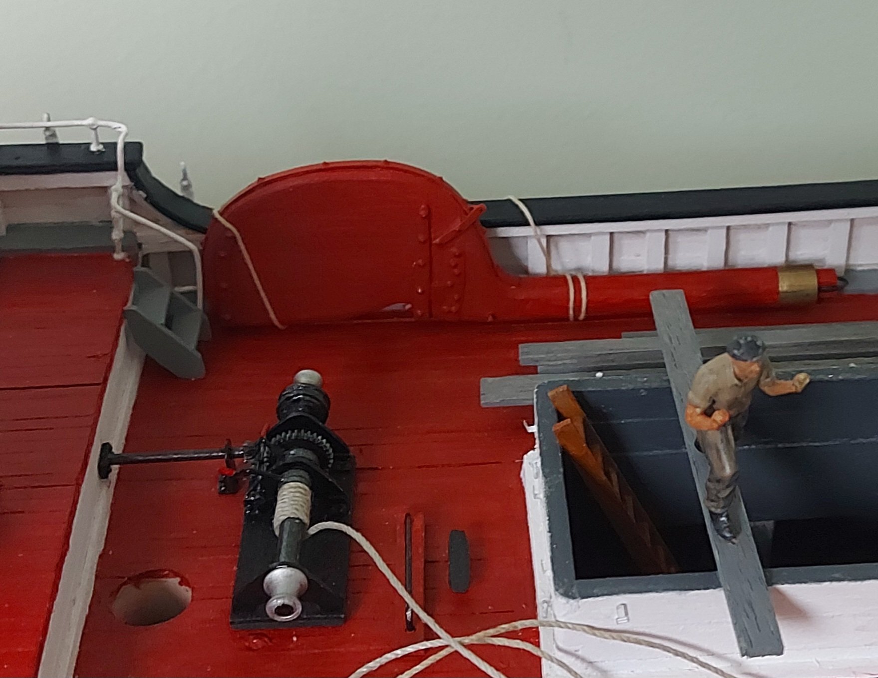
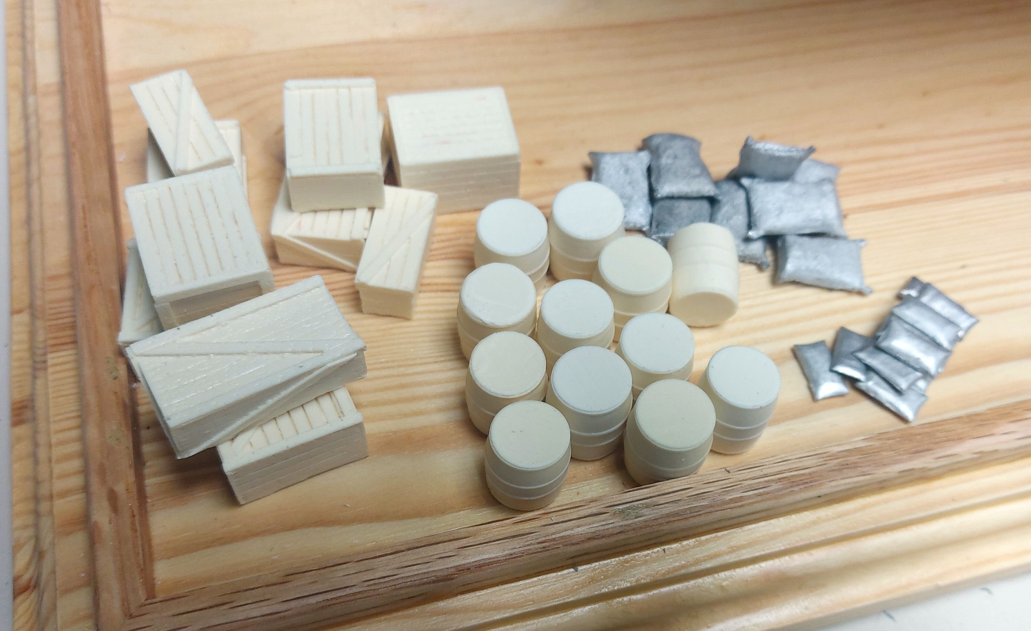
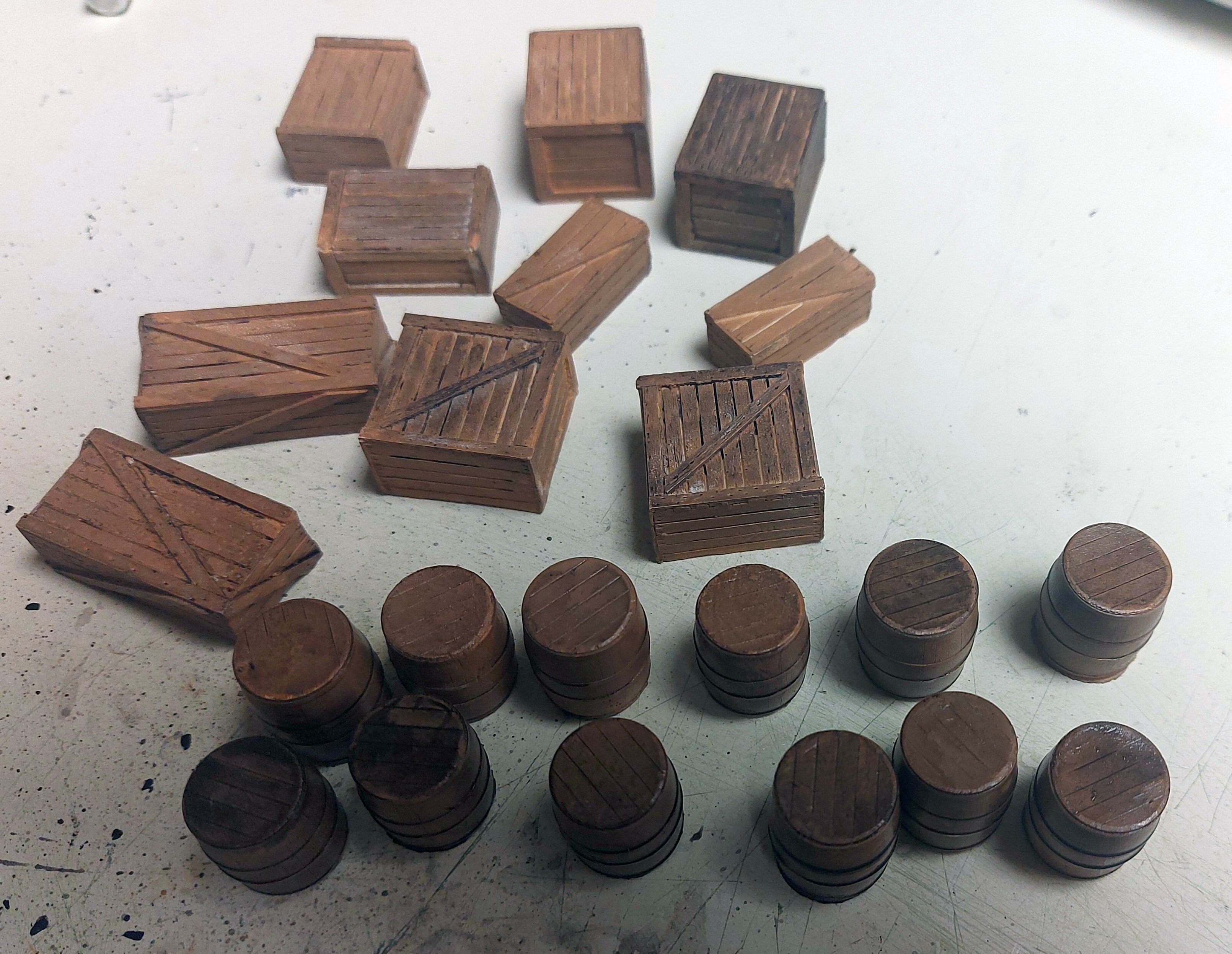
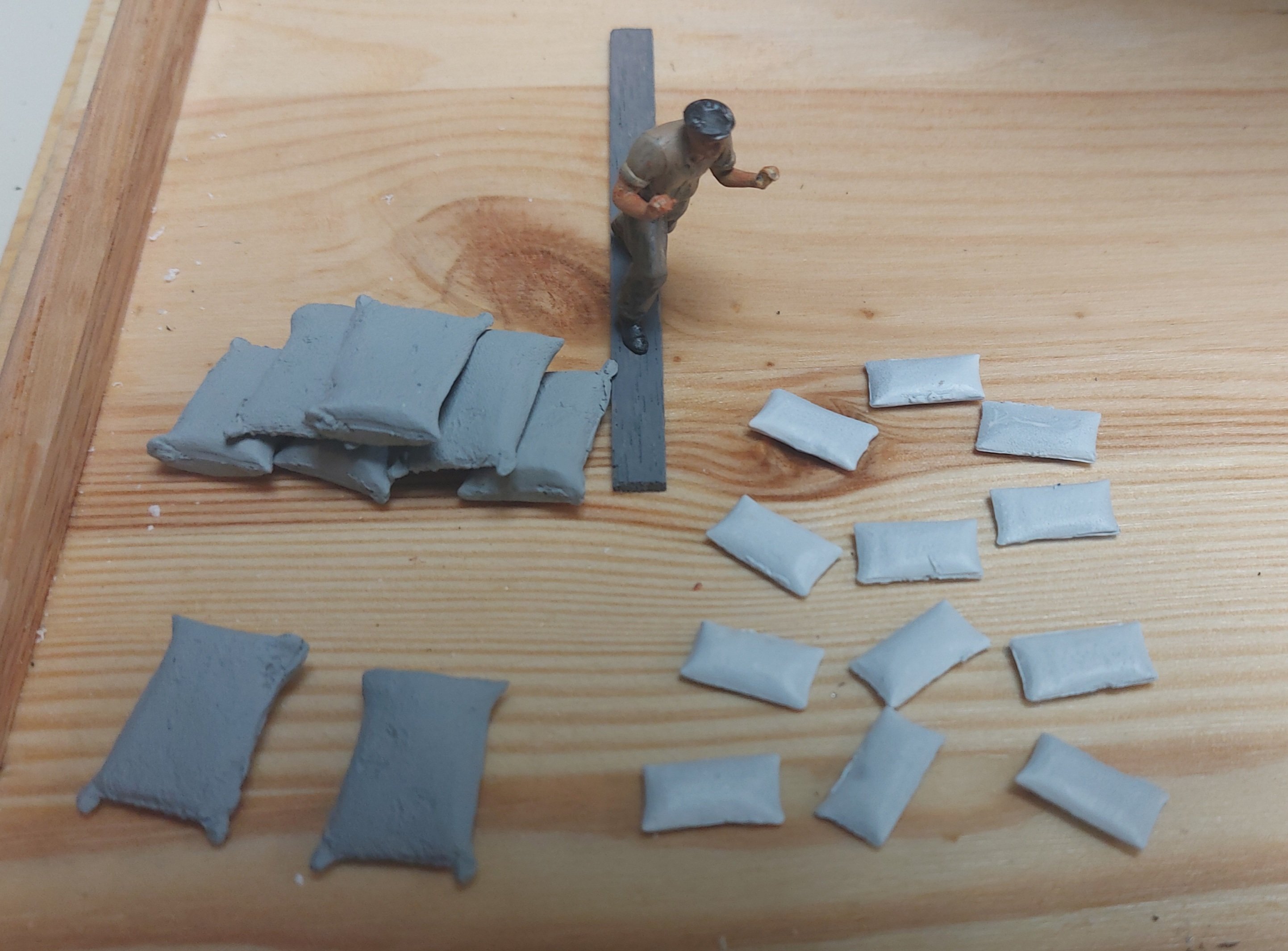
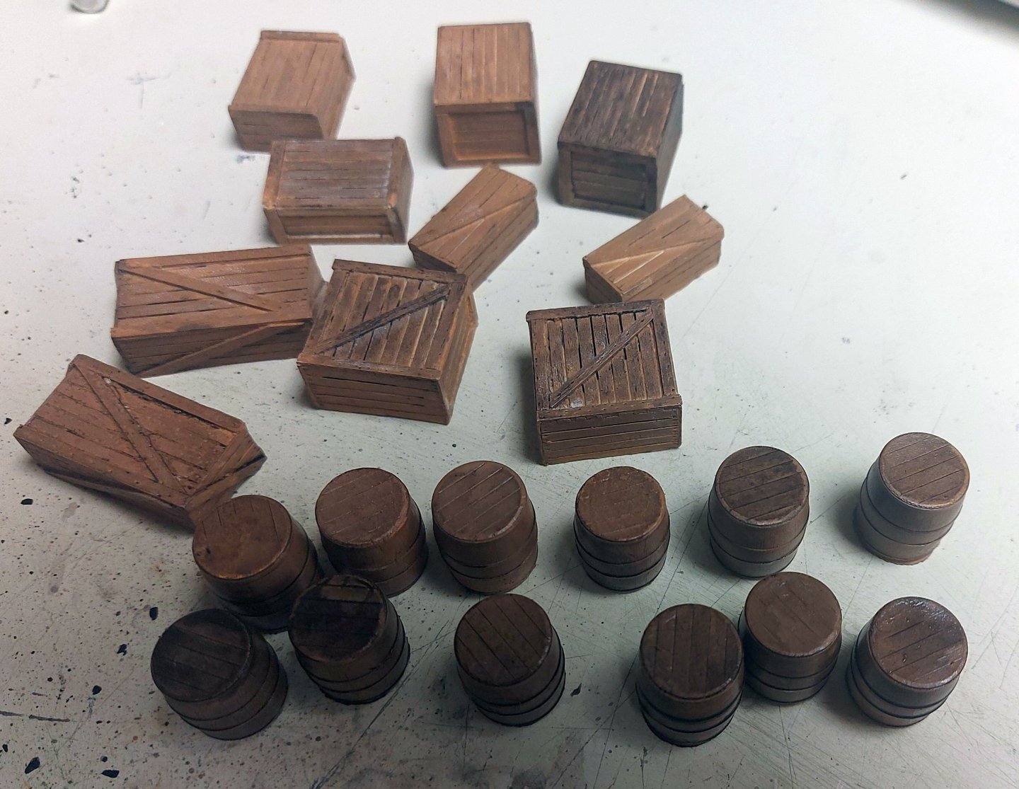
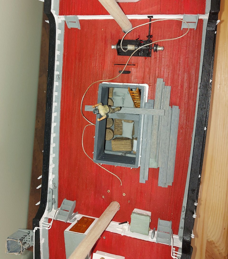
Santa arrived a couple of days ago, with assorted cargo for the hold! I was going to leave the hold empty to show the strong ice beams built into St. Roch, but once I decided to add a sailor unloading cargo I knew I had to have some cargo for him to work with! What arrived from Berkshire Valley (a model RR accessory company) was assorted sacks, crates, and barrels, all molded in O gauge, which is 1:48. There was just a bit of flash to clean off, then the parts, like anything coming from a mold, were rinsed thoroughly in warm soapy water to remove the mold release. Here is what they looked like: The resin parts after painting... And the cast metal sacks... the sailor has been glued to the plank he will be pushing his cargo along, in a sling suspended from the cargo derrick (one day soon!). Here is the cargo down the hold. The hatch cover canvas and boards are fixed onto the main deck, and the sailor is posed to push a sling of sacks... The details of the hold, and the ice beams, can still be seen. St. Roch shipped 150 tons of cargo for the various RCMP detachments she served, all had to be handled manually. If anyone asks me, she is at the far Eastern end of her supply run, thus almost empty! I want to thank all the forum members who gave me thoughts and ideas about the cargo scene! Regards, Bruce


- 368 replies
-
- 15
-
-