Lecrenb
-
Posts
271 -
Joined
-
Last visited
Content Type
Profiles
Forums
Gallery
Events
Everything posted by Lecrenb
-
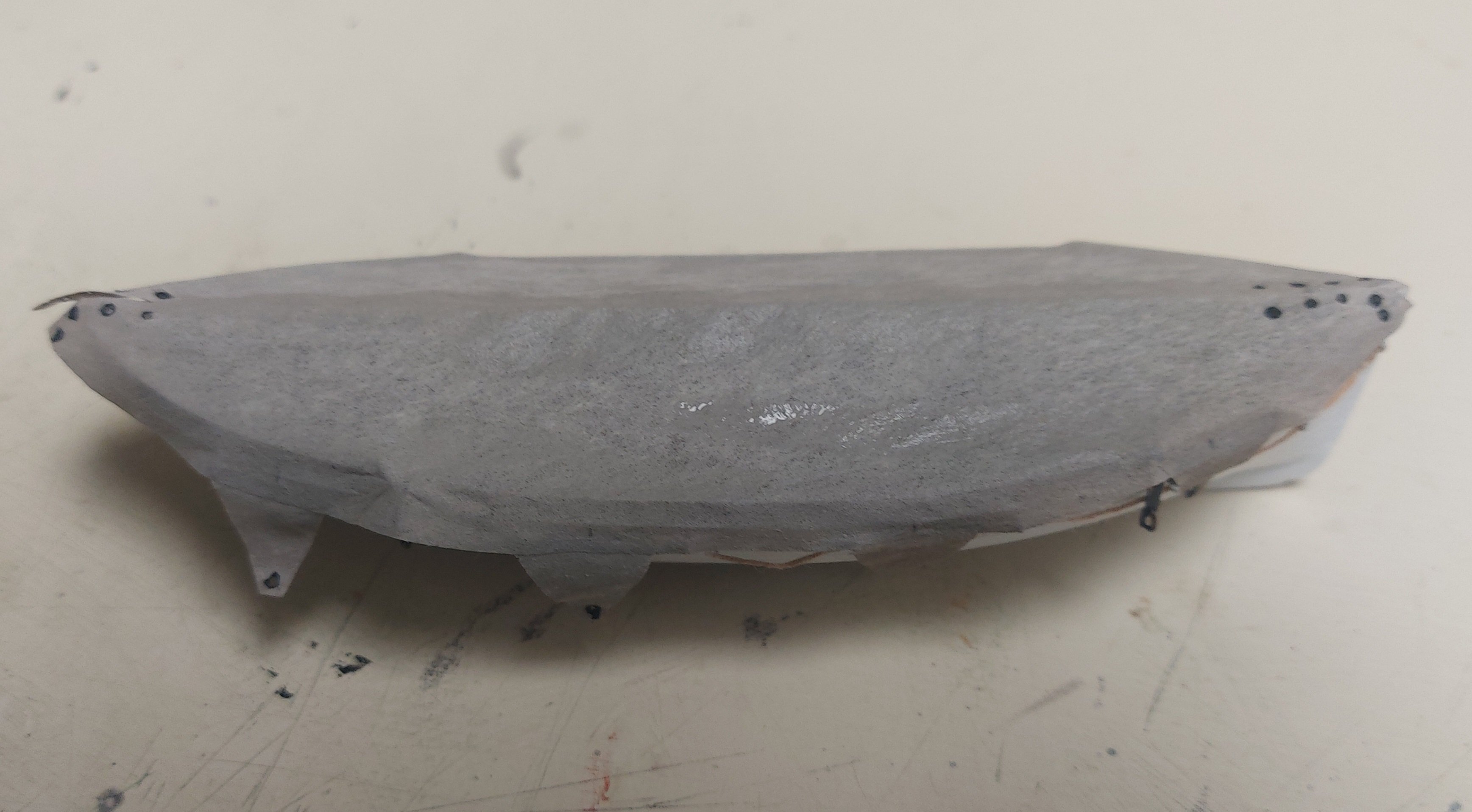
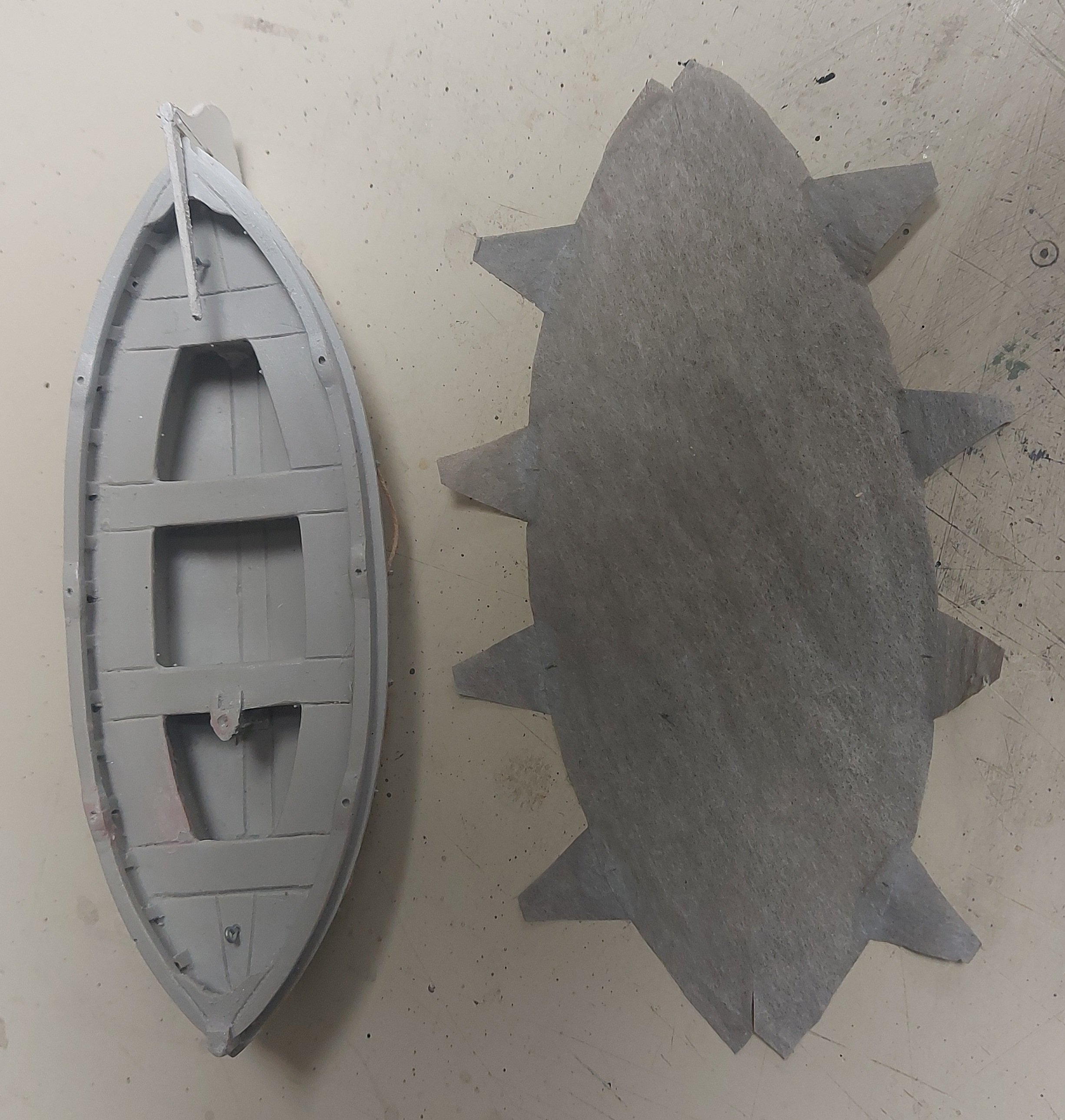
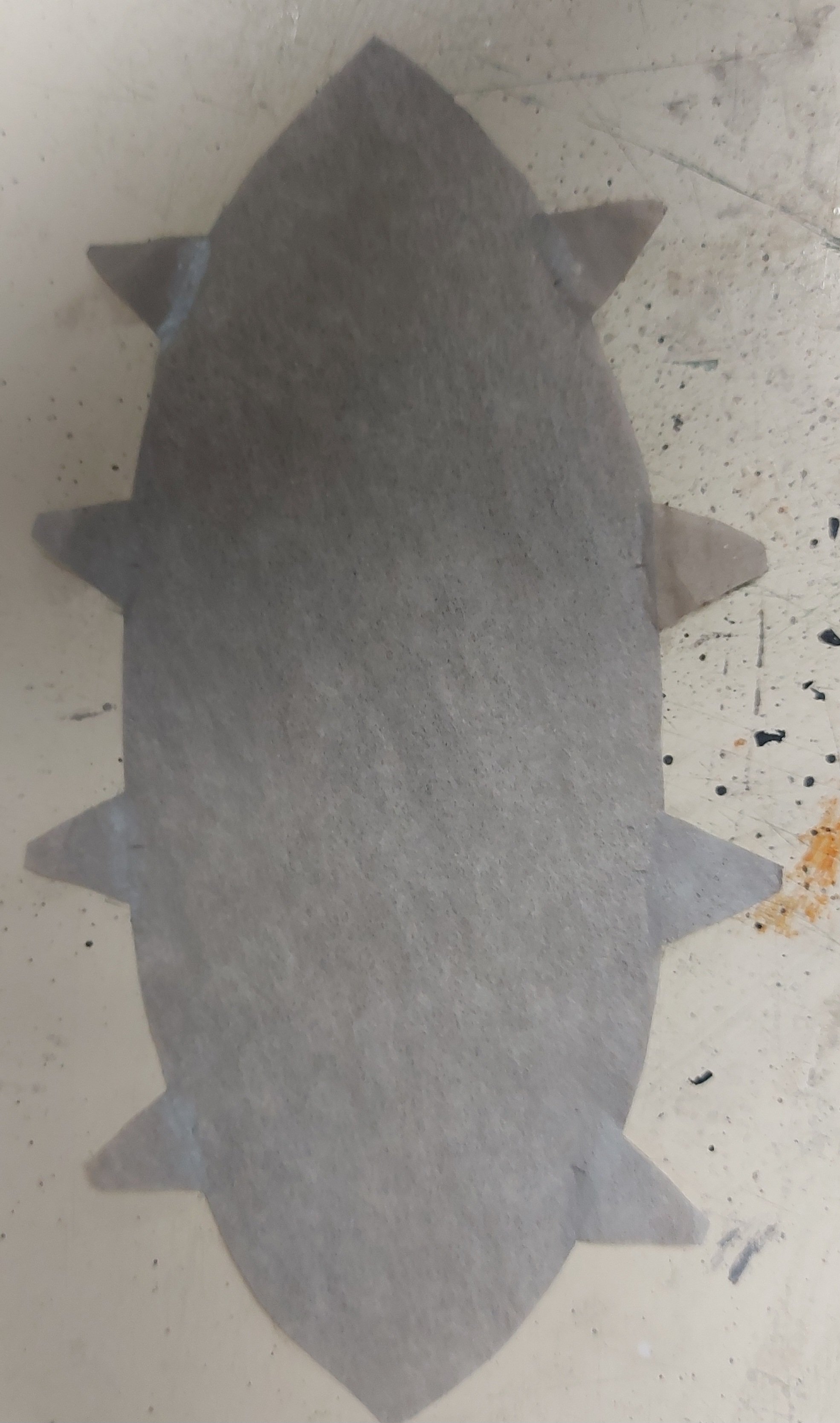
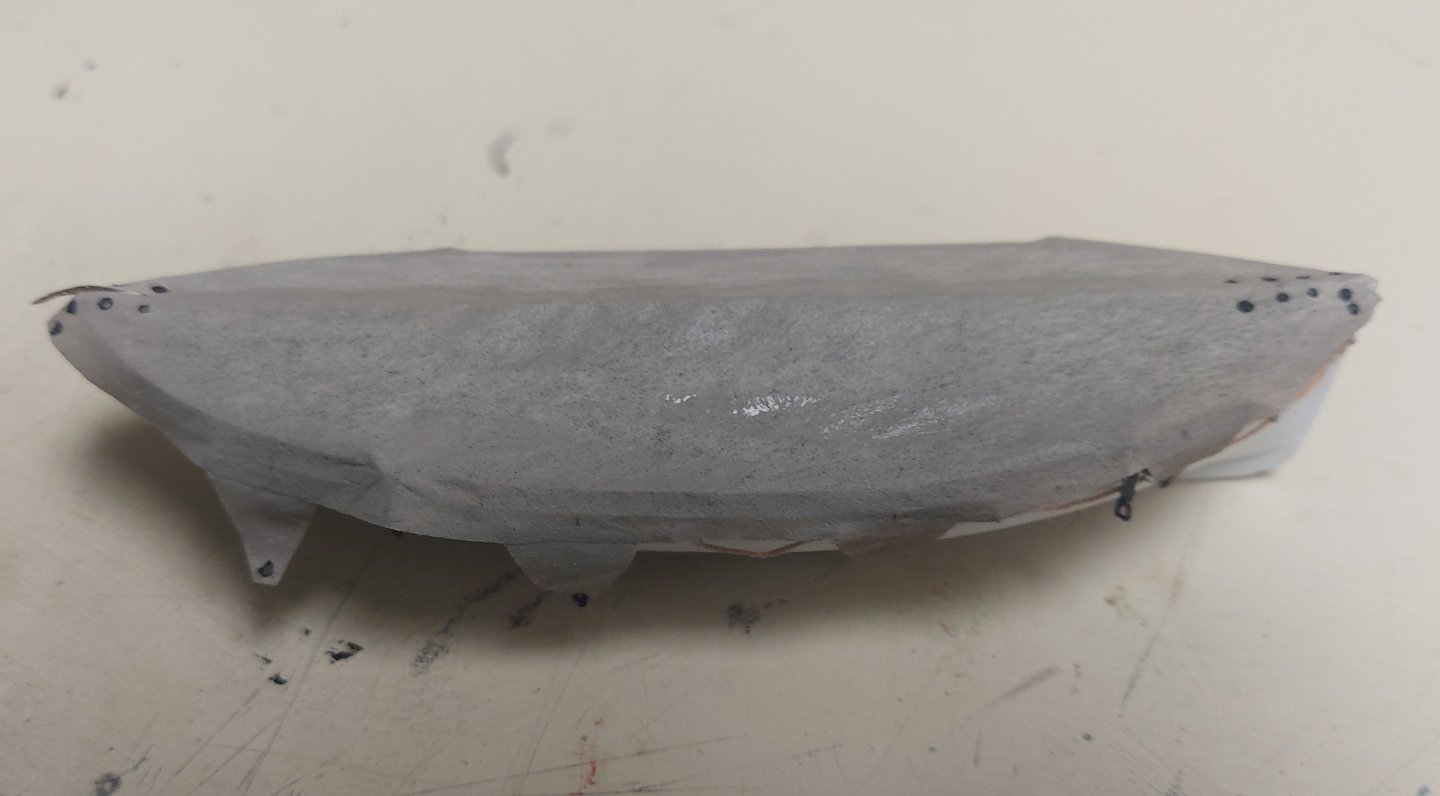
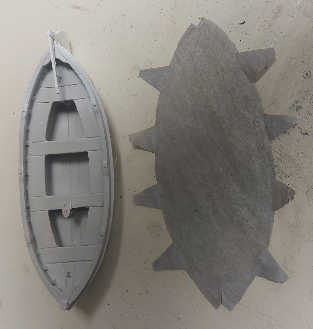
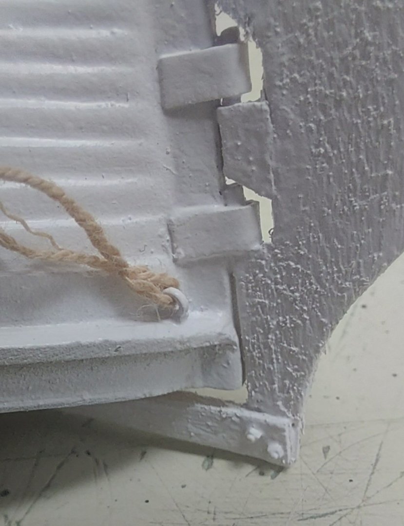
 Progress on the boat covers... the No Sew worked a treat, and bonded the 'darn cat ears' very well to the cover... I moved on to drill the grommet holes, and like David Antscherl said the holes drill cleanly in the painted silkspan. I used a tapered cocktail toothpick dipped in Tamiya XF-18 Semi-gloss Black to paint the grommets. Just dip the pointy end into the paint then into the grommet hole, it leaves a neat painted circle. After that I prepared the motorboat by gluing a spar bow to stern to 'tent' the cover like the original, and also glued the gripes in place. The picture shows the boat and cover to this point. Next I centered the cover over the boat and used a water soaked paint brush to wet it, enough to start getting a tent shape and fold around the edges, and the 'darn cat ears' stayed on, Yay! I left it at this point to dry, I will give it another wetting before lashing the cover to the boat. First I have to lash the triple blocks to the eyebolts in the boat, these will be the lower part of the falls. Almost made a mistake when I forgot to make sure the 'darn cat ears' would not interfere with the gripes, but fortunately there were no conflicts! So far so good, so I made a start on the dinghy. Since it is done the same as the motorboat I won't repeat the details in this log. Next time you see the boats they should be in their chocks with everything lashed down!
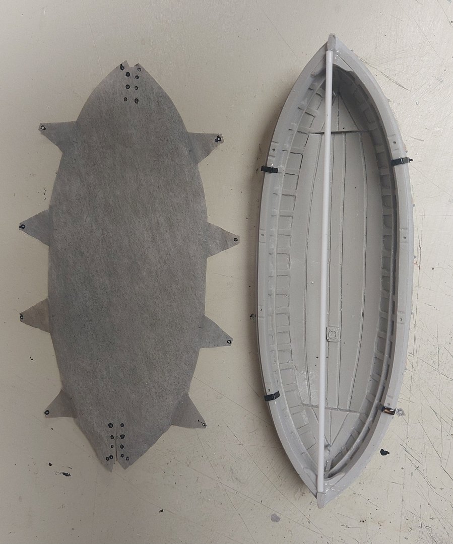
- 384 replies
-
- 11
-

-

-
Thanks Bill, your boat cover looks great! nice idea about gluing a strip around the edge, I'm hoping mine fold over when wetted without the triangular pieces falling off! Regards, Bruce
-
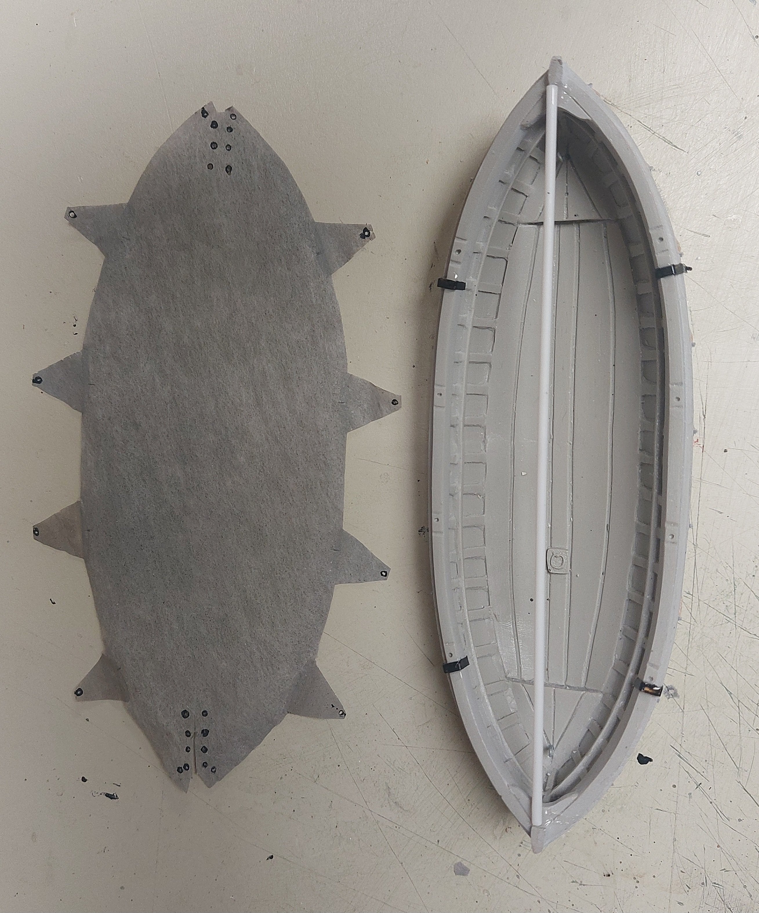
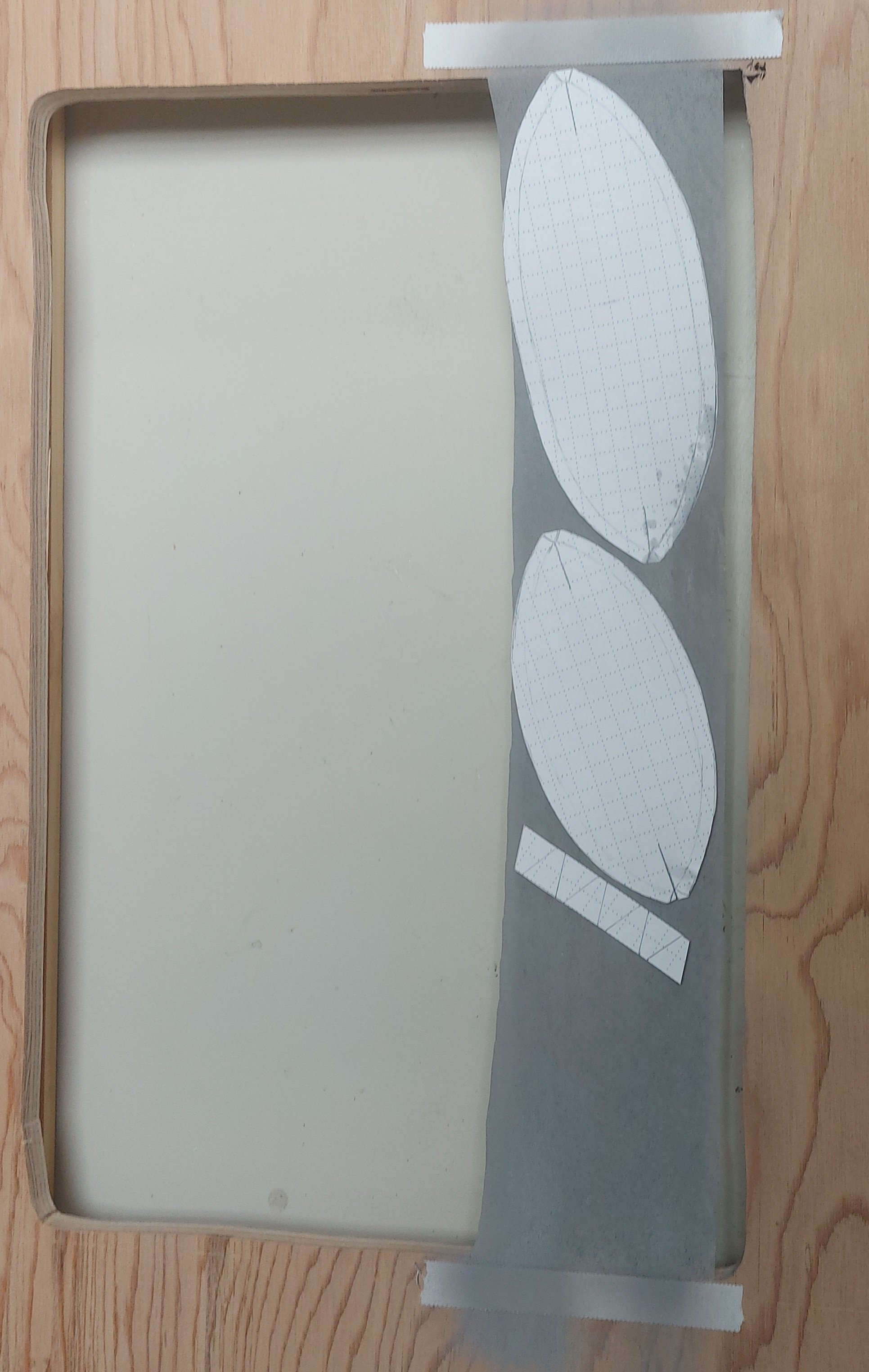
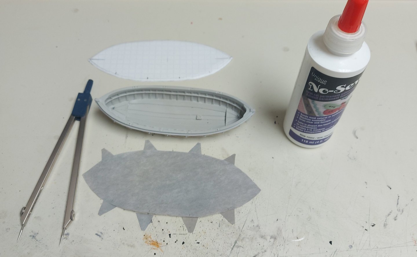
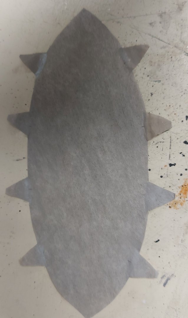
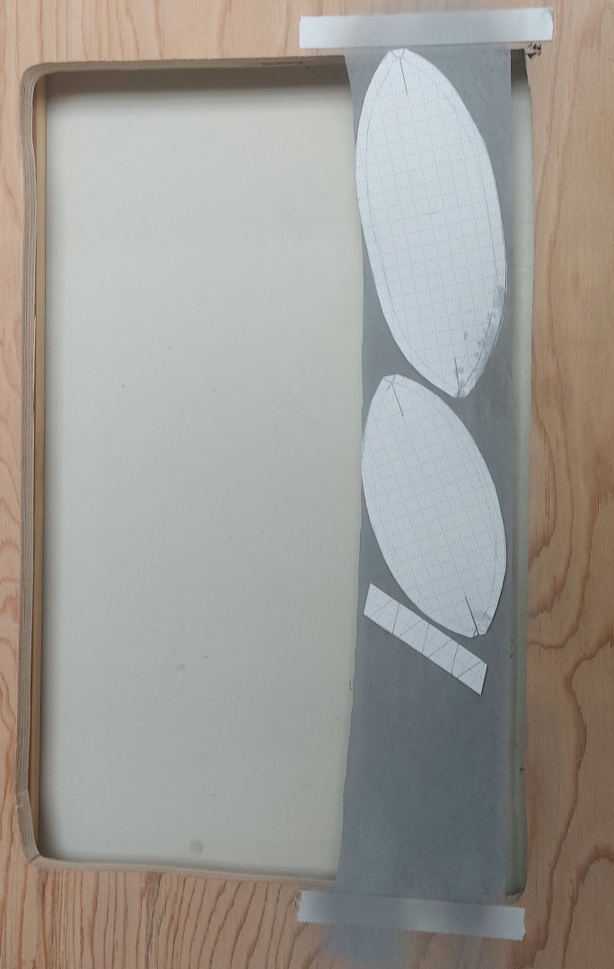
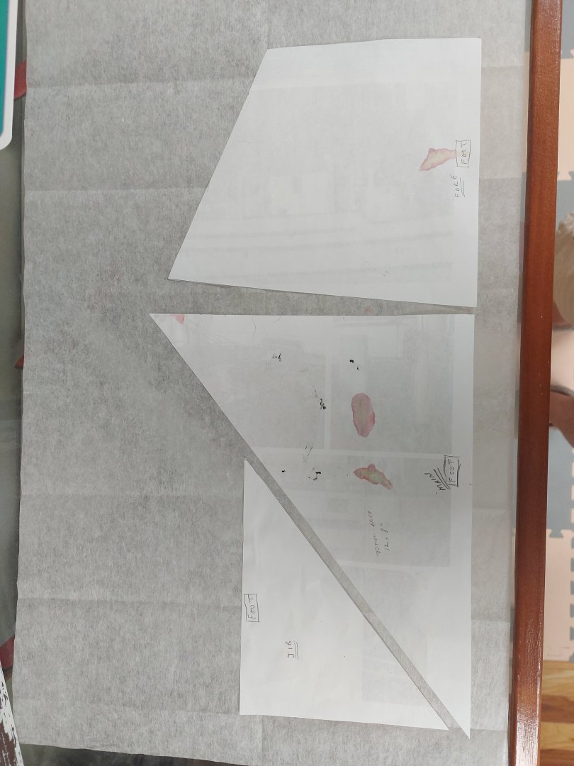
After some back and forth with the airbrush I am happy with this shade for the boat covers... the picture shows the paper template, the cover pieces cut from the silkspan, and the 20' motorboat... The triangular pieces are the tie downs (not sure if they have a nautical name or not?) They are just set in place to see how things look. David Antscherl recommends Matte Medium for gluing silkspan pieces together. I have lots of 'No Sew' on hand so I'm giving that a try. I have used it before with great success gluing flags to halliards and anything else involving fabrics. It dries clear and flexible, and once set up it can be washed, so it is waterproof. Here is the motorboat cover assembled, waiting for the No Sew to dry. We'll see how it holds together when I wet the cover to fit the boat, and when I lash it down... I'm going to give it a day and maybe a second application from the back side... delving into uncharted territory here!
-
Our cruise was with Viking, Paris to Rouen and back including Giverny, the Bayeux Tapestry and Juno Beach. We arranged a private guided tour of the cathedral and absorbed a lot of knowledge about gothic architecture and the history of the building. The lines moved fairly quickly... Unfortunately we did not have time to visit La Musee de la Marine... or Honfleur... next time!
-
Hi Wefalck... we enjoyed our cruise on the Seine, and the restored Notre Dame is amazing! I agree about the colour choice and I will shoot a thin coat of flat white onto my boat covers. Pictures I have show St. Roch's boat covers sometimes light, sometimes darker... could be the lighting or camera settings with black & white film... Yes, her sails today are reproductions, but originally they were cotton canvas. I'm also thinking about a light gray, off-white, for the sails and we'll see how they turn out! I appreciate your feedback, Bruce
-
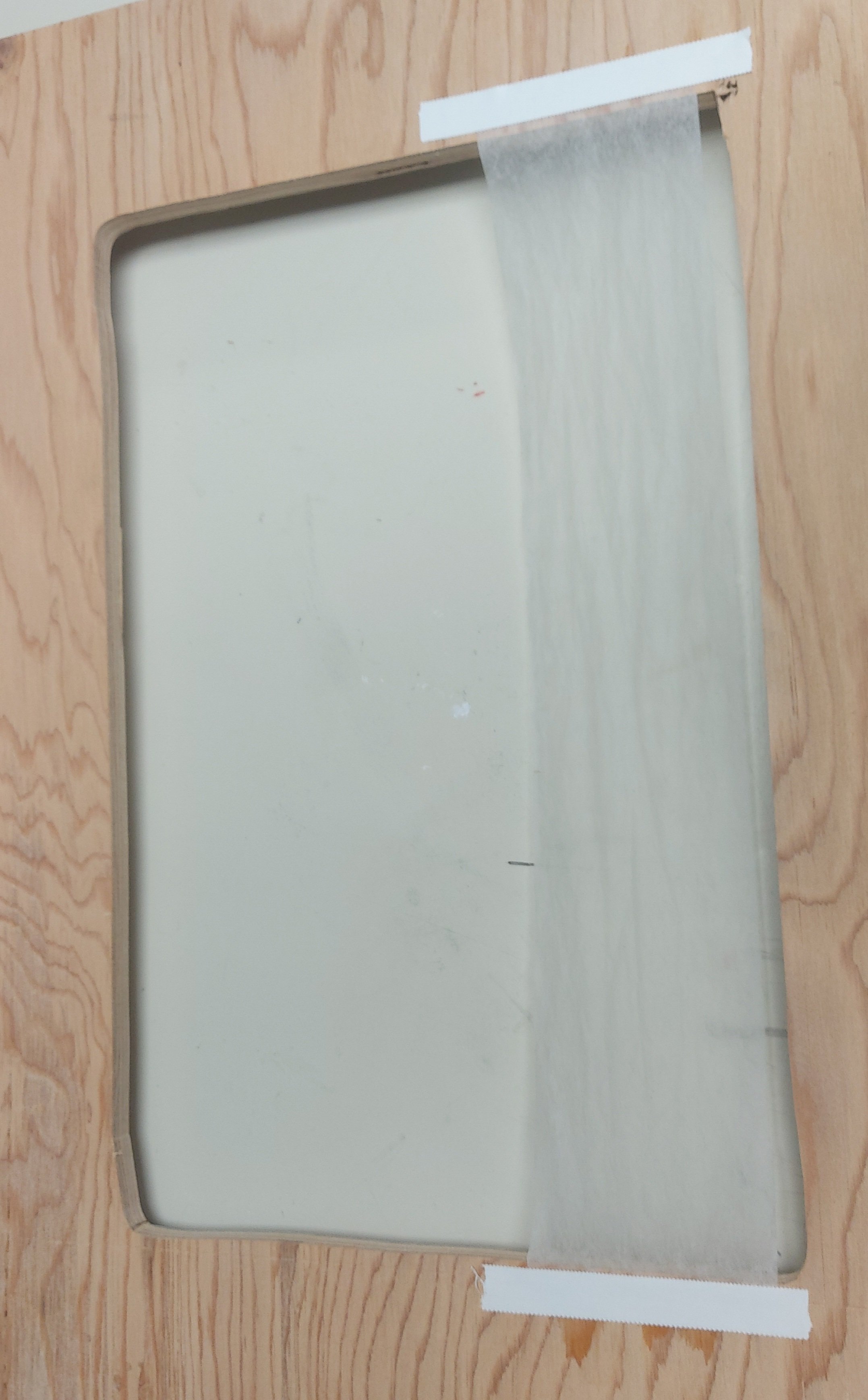
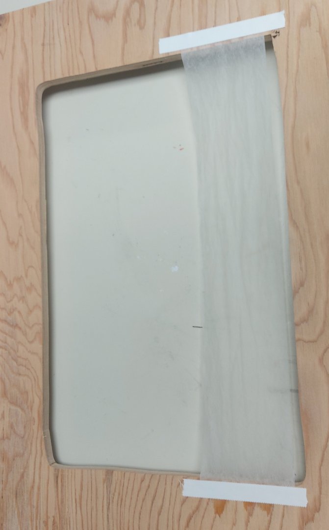
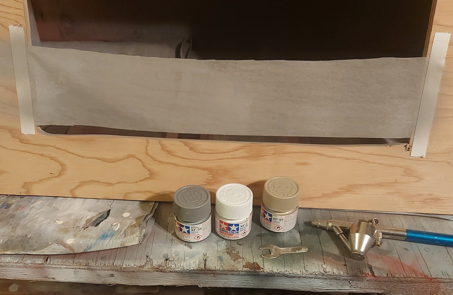
I'm back, and well rested! So back to the silkspan... I decided to first work with an offcut to make the boat covers. This leaves the main piece of silkspan for the sails, and if I mess up the offcut I can still make the sails (I hope)! I had previously (on page 8 of this build log) made the frame to hold the silkspan. Now I wetted the offcut and taped it onto the frame, per David Antscherl's directions. I deviated by using medical adhesive tape since I could not get the paper packing tape in Beaumont. It is waterproof and seems to work very well. Taping two sides vs. all four did not seem to matter on a piece this size. Here is the wet silkspan drying on the frame. Next I coloured the silkspan to match what I think the boat cover canvas would have looked like. Rather than the artist's tube paints recommended by David I chose to use my Tamiya acrylics. Buying tube paints would leave me enough left over that I could will them to my heirs! The Tamiya paints are water based and give me a broader range of colours, and would go on with my airbrush, which I considered a better technique than brushing. I used a base of flat white, and added a drop of buff and another of dark sea gray. My airbrush cup was about half full, so I topped it with Tamiya thinner and sprayed it onto the silkspan. Here it is in the spray booth. I laid down two coats, light enough that there were no runs. When I moved he frame to my bench I saw that the colour was more gray than I would have liked. Memo to self, better lighting at the paint booth! Here it is drying on the bench with the boat cover templates laid on top. After it dries, if I am still not satisfied, I'll shoot another coat of diluted buff to try and get more of a canvas colour... we'll see. Next will be to cut out and assemble the covers, then try to get them to fold nicely over the boats... Thanks for looking in, tips and critiques are always welcome!
- 384 replies
-
- 10
-
-
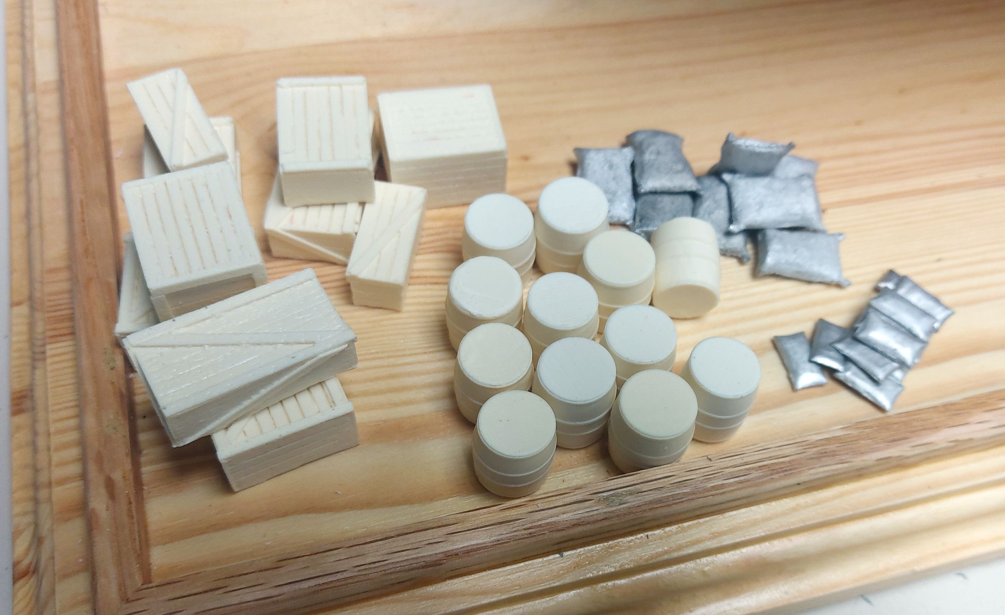
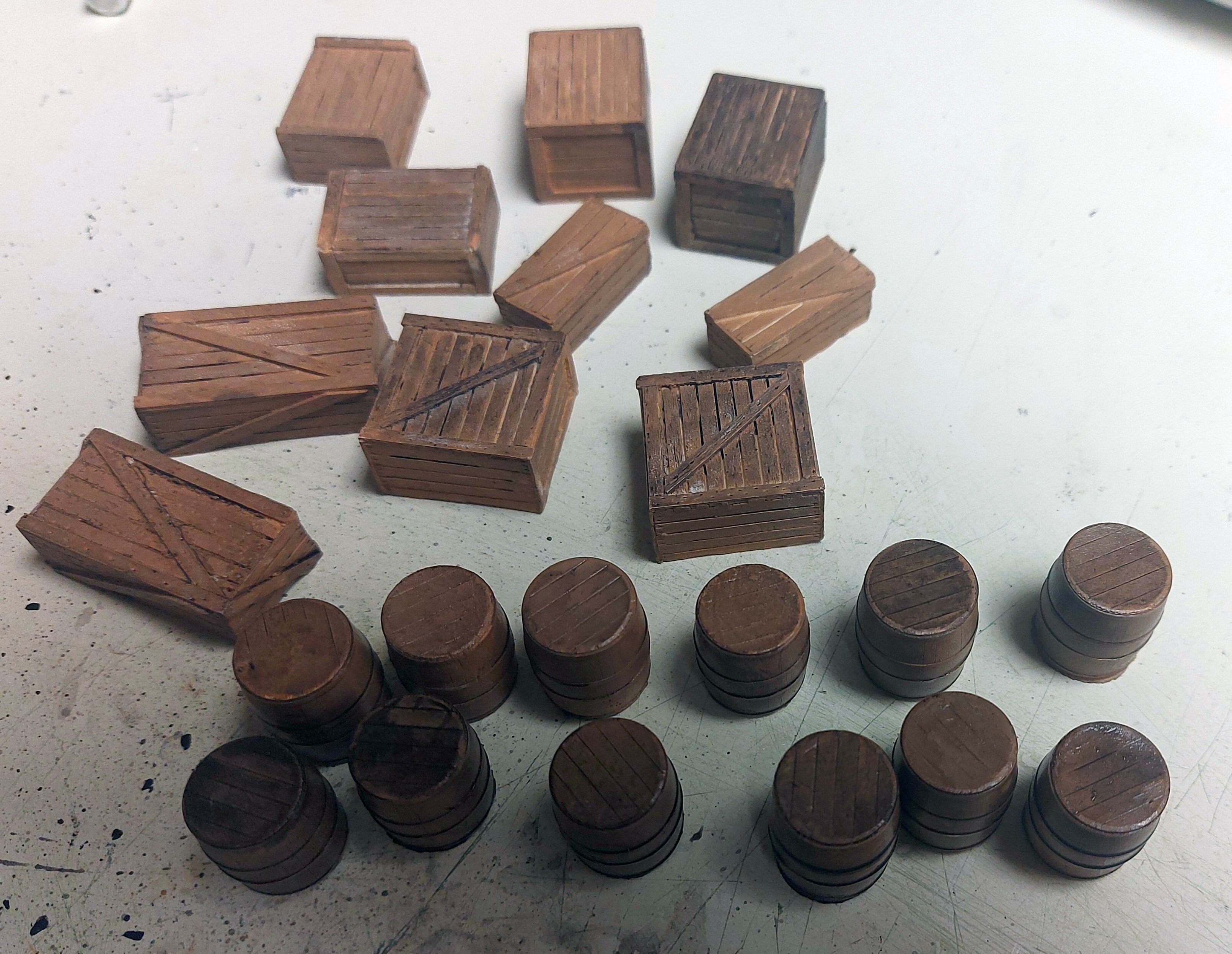
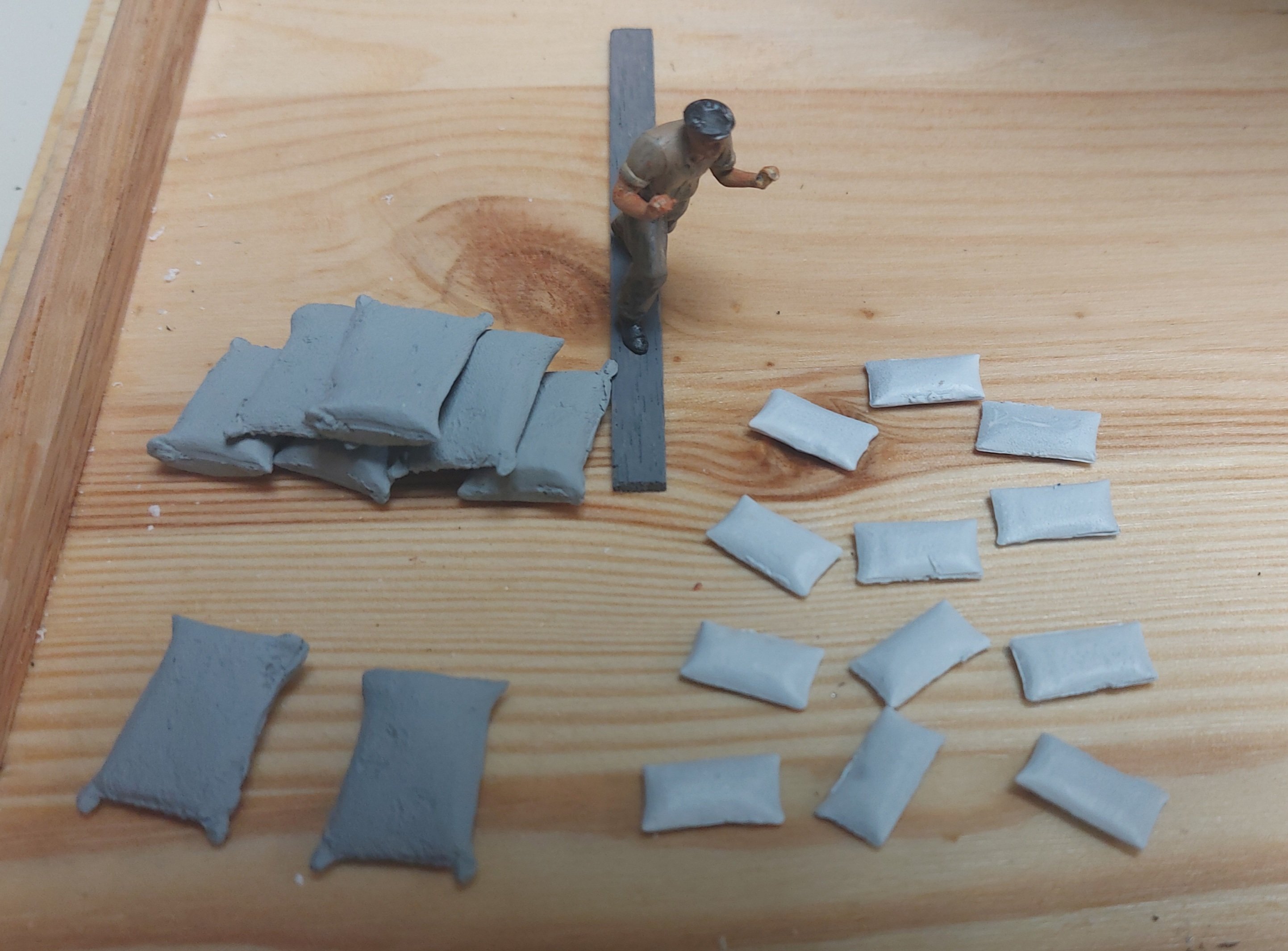
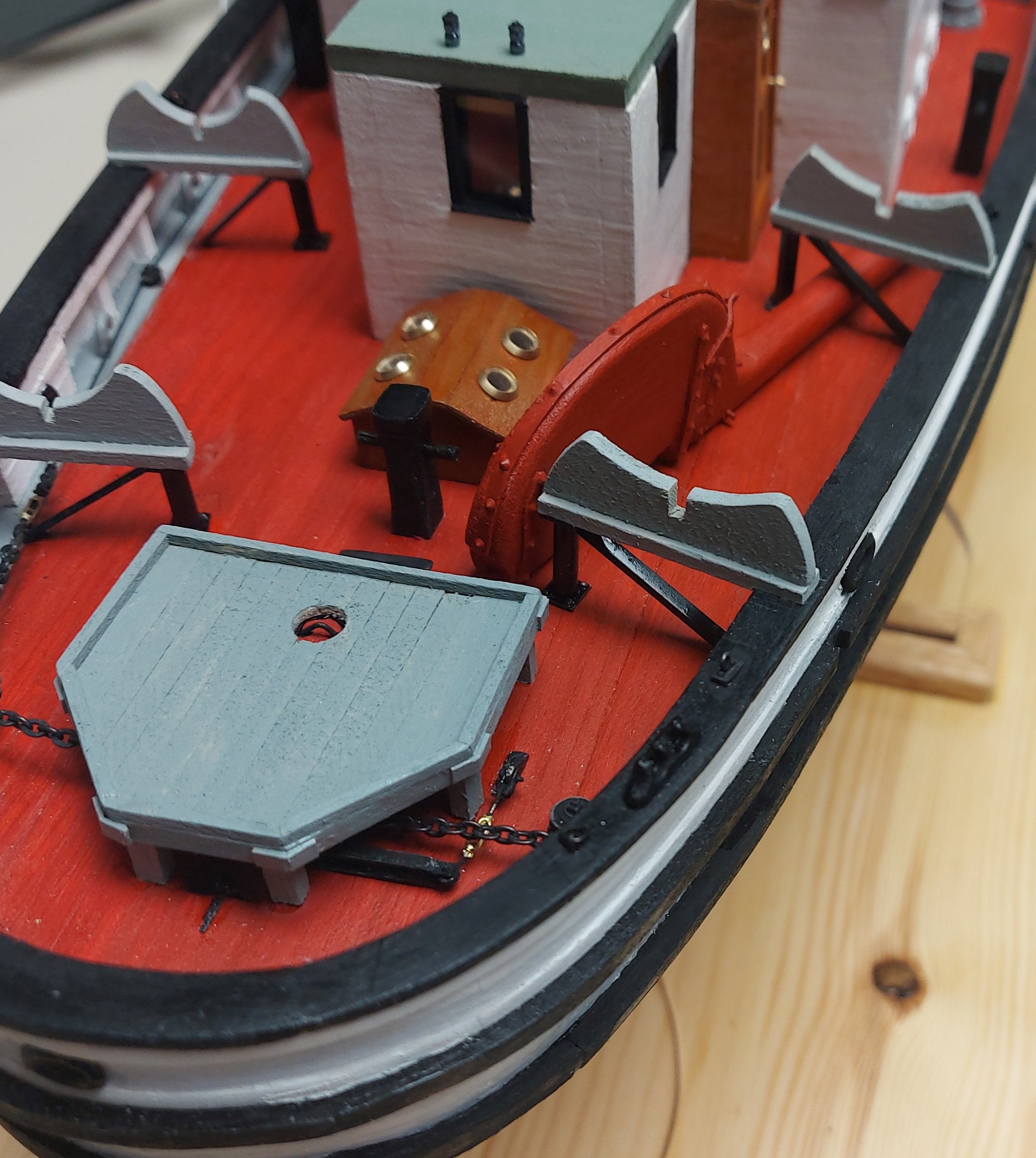
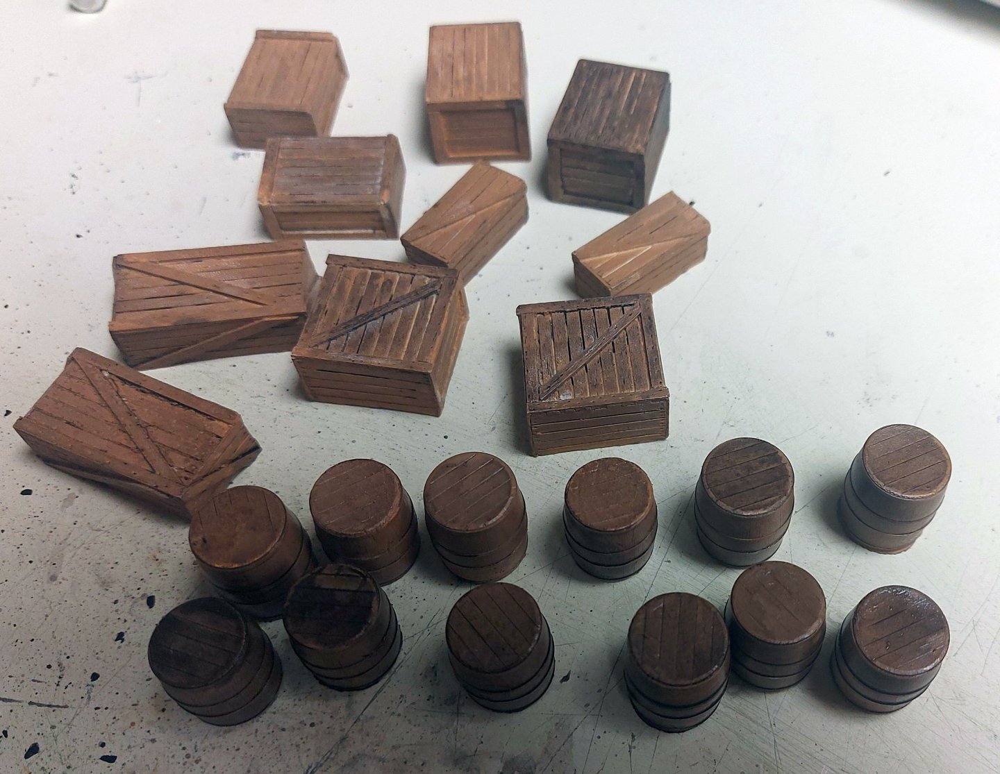
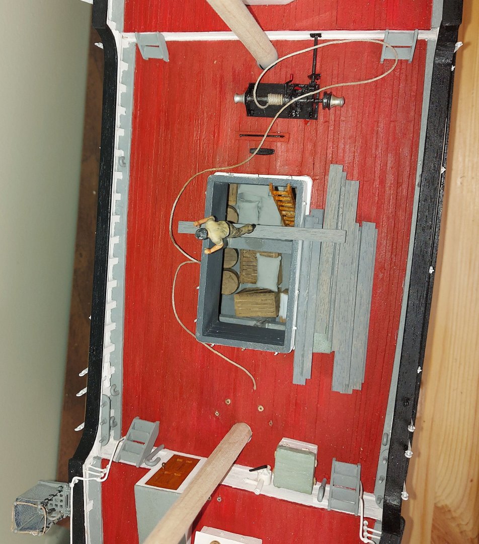
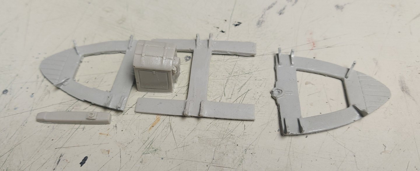
Santa arrived a couple of days ago, with assorted cargo for the hold! I was going to leave the hold empty to show the strong ice beams built into St. Roch, but once I decided to add a sailor unloading cargo I knew I had to have some cargo for him to work with! What arrived from Berkshire Valley (a model RR accessory company) was assorted sacks, crates, and barrels, all molded in O gauge, which is 1:48. There was just a bit of flash to clean off, then the parts, like anything coming from a mold, were rinsed thoroughly in warm soapy water to remove the mold release. Here is what they looked like: The resin parts after painting... And the cast metal sacks... the sailor has been glued to the plank he will be pushing his cargo along, in a sling suspended from the cargo derrick (one day soon!). Here is the cargo down the hold. The hatch cover canvas and boards are fixed onto the main deck, and the sailor is posed to push a sling of sacks... The details of the hold, and the ice beams, can still be seen. St. Roch shipped 150 tons of cargo for the various RCMP detachments she served, all had to be handled manually. If anyone asks me, she is at the far Eastern end of her supply run, thus almost empty! I want to thank all the forum members who gave me thoughts and ideas about the cargo scene! Regards, Bruce


- 384 replies
-
- 15
-
-
-
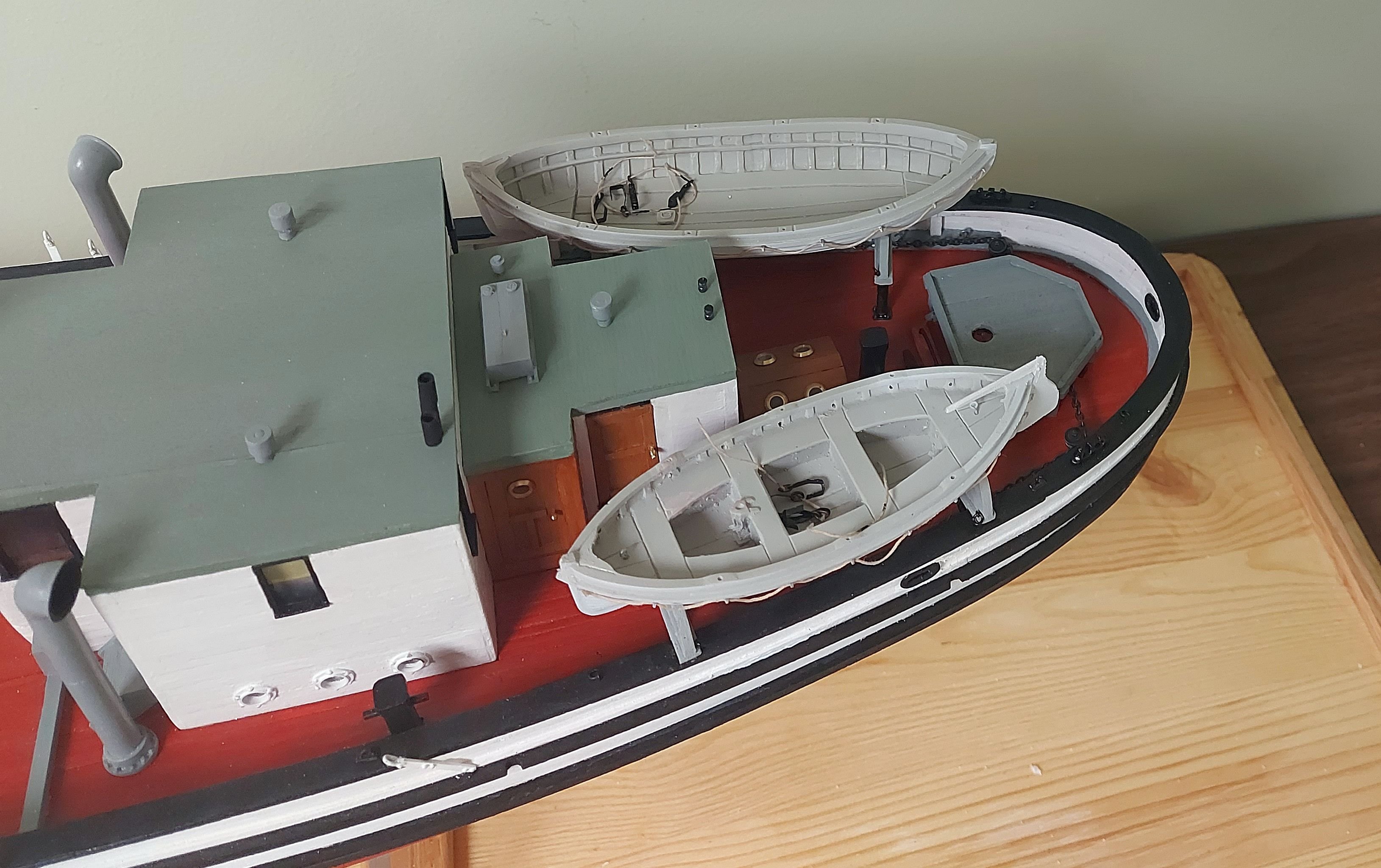
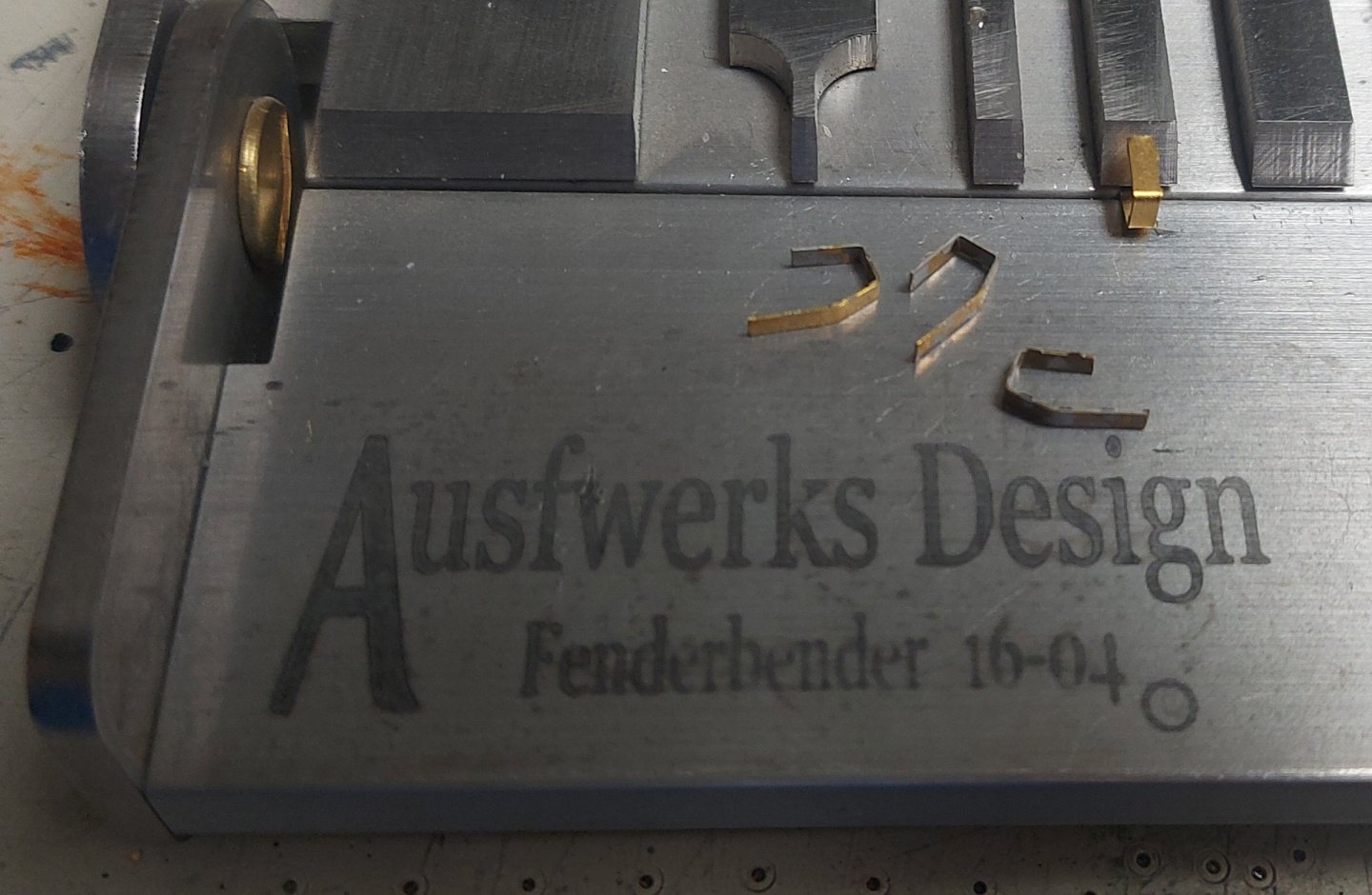
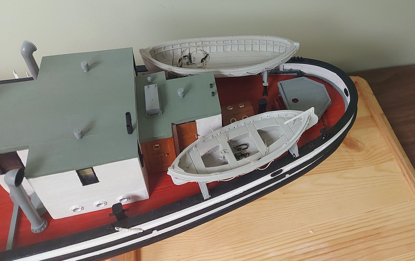
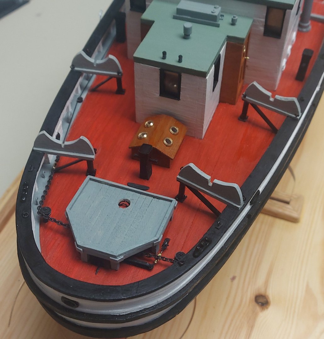
I used my Ausfwerks Fenderbender (so named because at 7 inches long it can bend the fenders on armored fighting vehicle models in one operation) to form the gripes for the boats. This is a true miniature brake and the best engineered product I have seen. Unfortunately it is no longer in production. I am not going to be able to make the boat covers before I go away for a bit, so here are the boats in their cradles, with the gripes inside, waiting for me to get back to them! The poop deck gets even more crowded after the new superstructure is added in 1944, but for now the spare rudder can still fit along or under one of the boats! Thanks for looking in!
-
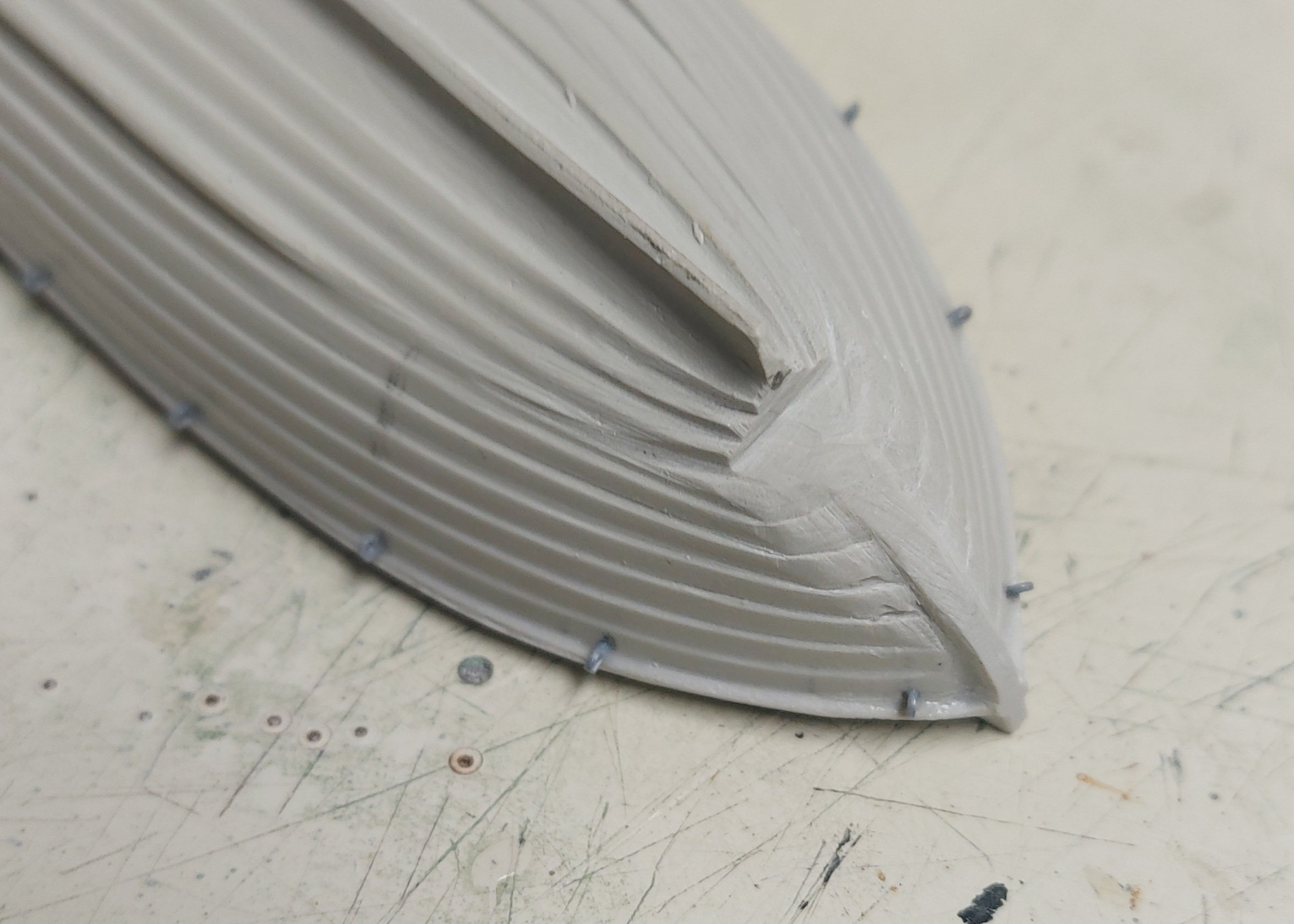
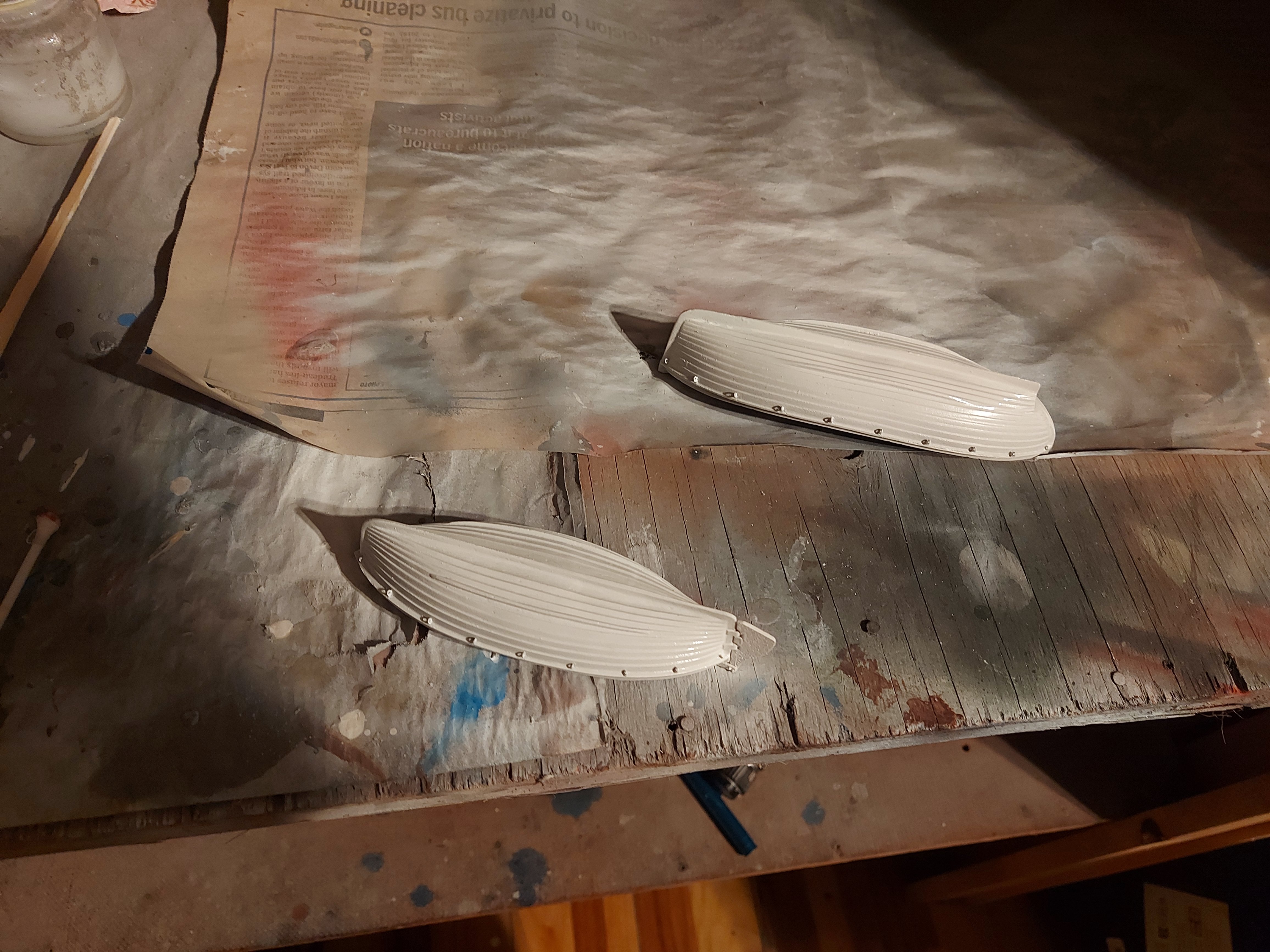
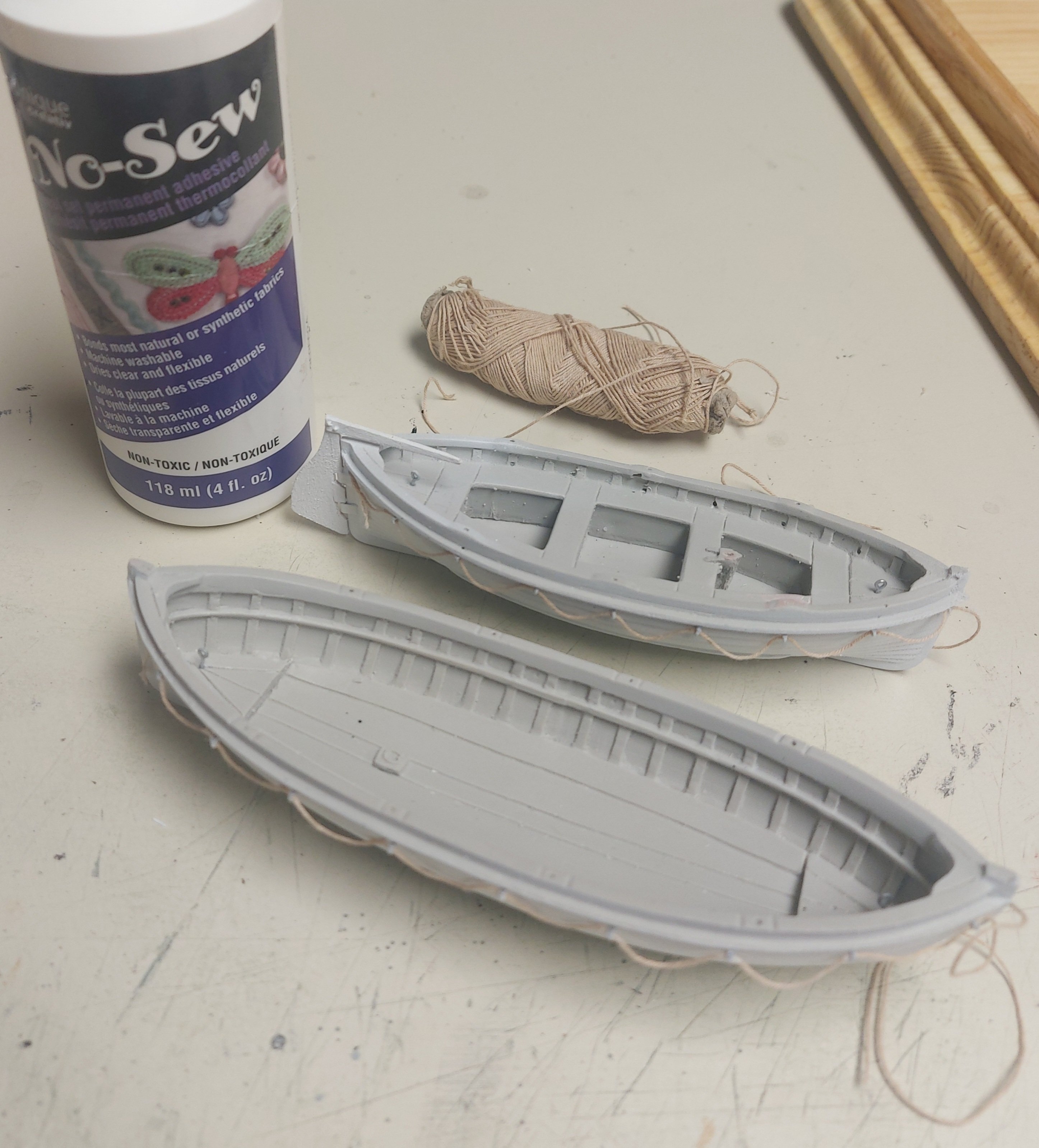
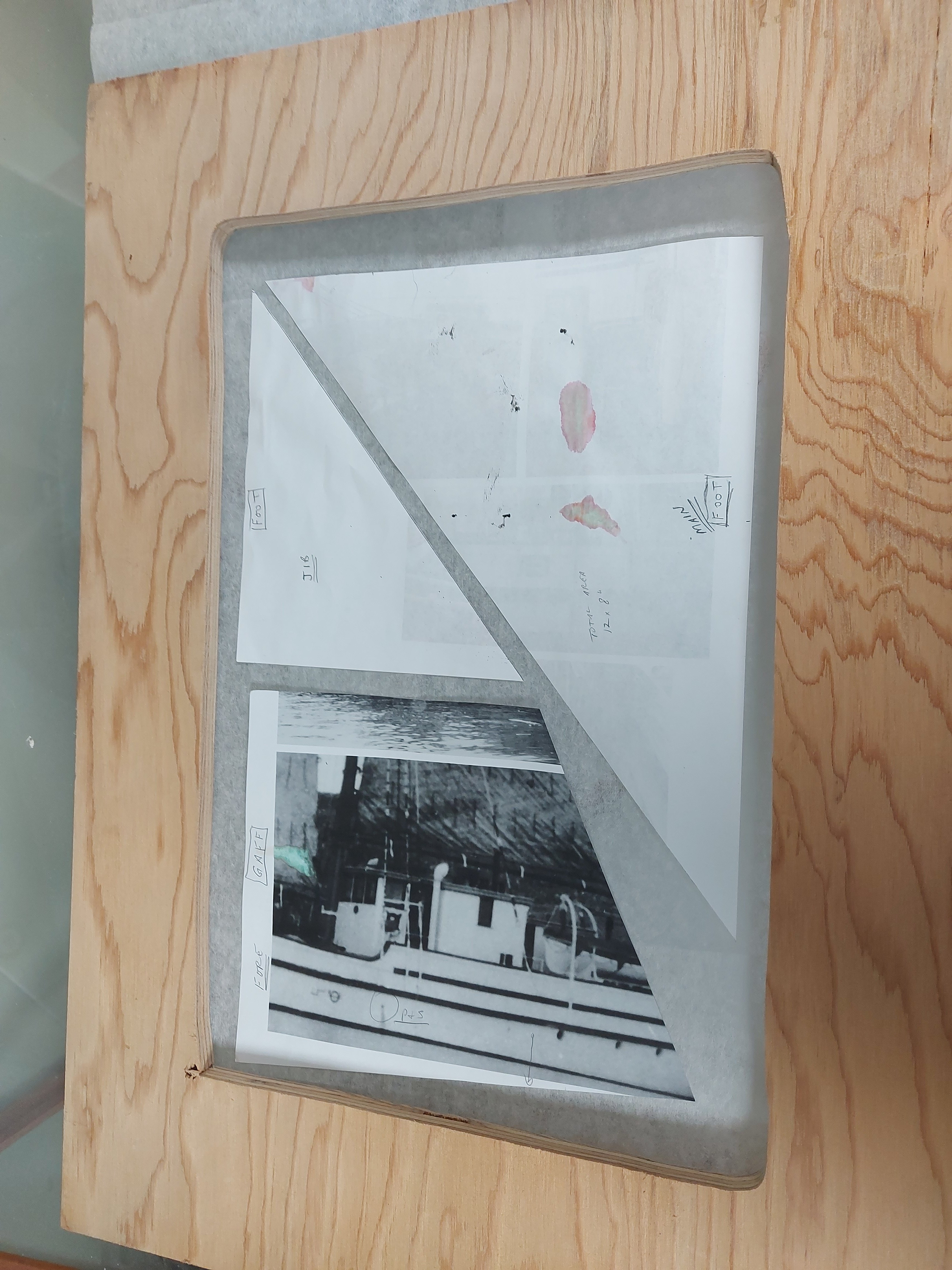
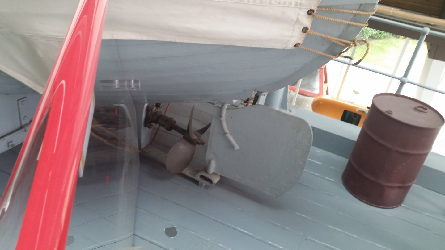
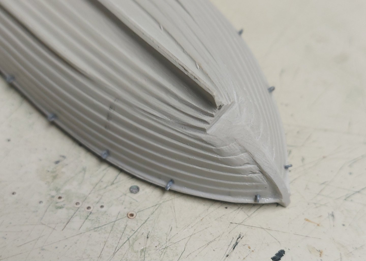
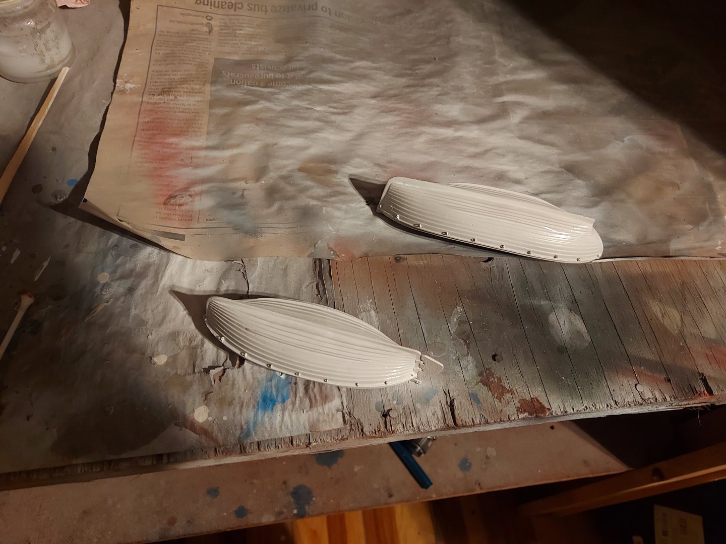
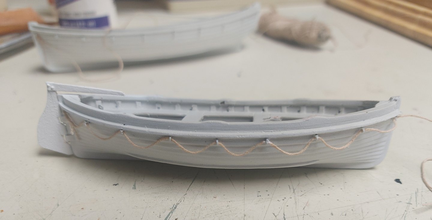
A rainy morning here in Alberta, so a good time to get some work done on St. Roch's boats... First I needed to carve back the stern of the motorboat. The first picture is St. Roch's motorboat showing the rudder and prop; this is what I am trying to emulate with the second picture... Then it was off to the paint booth... After the paint dried it was time to reeve the lifelines around each boat. I made eye splices at the end of each line... Here are the boats with the line and glue I used, ready for the final line splicing once the glue dries. I used 'No Sew' fabric glue to tack the lines into position... this dries clear and flexible, and will hold the lines in the proper shape while I make the final splices. Next I am going to make a start with the silkspan sails, and make the boat gripes and covers. Then the davits should complete the hull work on the ship except for putting some cargo in the hold. It will be very exciting to put the hull aside and start finishing the masts!

- 384 replies
-
- 12
-
-
Thanks for the link Wefalck, I read it with interest! It seems the three methods I have come across so far are very similar, so I will proceed with reference to all three and hopefully everything will come out looking good!
-
Thanks very much Dr! I followed your link with interest, and followed on through your trials and tribulations with rigging your schooner. I must say Well Done Sir! After reading your link I have decided that airbrushing my acrylics onto the silkspan should give suitable results, so I will try that and see how things progress. I will also tape the silkspan to the frame then shoot water onto it, should help to avoid tearing! Regards, Bruce
-
Thanks Wefalck! I have heard the restoration paper referred to as Japanese tissue, and seen it used on the tv show "The Repair Shop". I was going to try it until my friend gave me some silkspan. Looking forward to Paris on the 16th!
-
Very nice and frame worthy Alan!
-
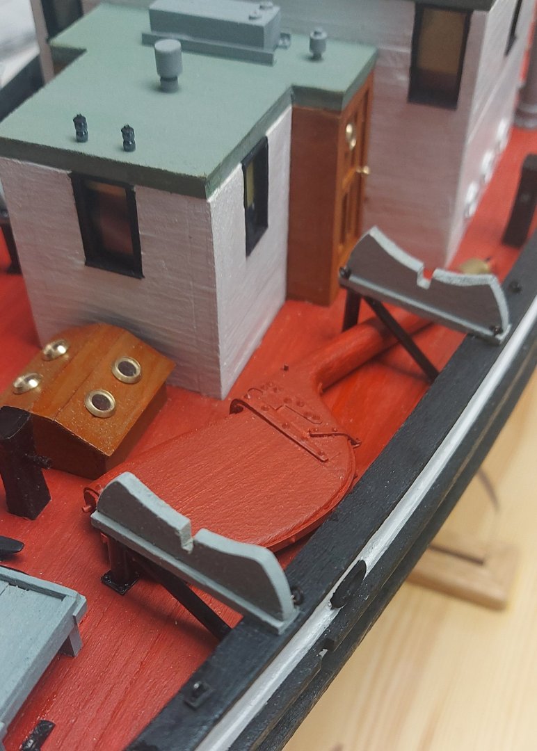
I also got the boat cradles complete, now they are waiting for their boats... I now fussed around with the spare rudder, and found two ways in which it could in fact be stowed aft... The rudder is presently stowed on St. Roch's main deck, from where it would be tremendously difficult to get it aft, past the full breadth superstructure, if it was ever needed. The larger superstructure would also preclude the rudder from being stowed aft. I also don't believe the mizzen mast that was installed in 1944 had the geometry or capacity to replace the rudder if needed, unlike the previous main sail boom. I wasn't sure if there would be room after my 1930 deckhouse was built, but pictures do not show it on the main deck, so where else would it go? The next pictures give a couple of options: I think the last picture is the best guess, since the rudder would not interfere with the boat lashings. I intend to send my pics off to the Vancouver museum and ask their opinion... wish me luck!

- 384 replies
-
- 12
-
-
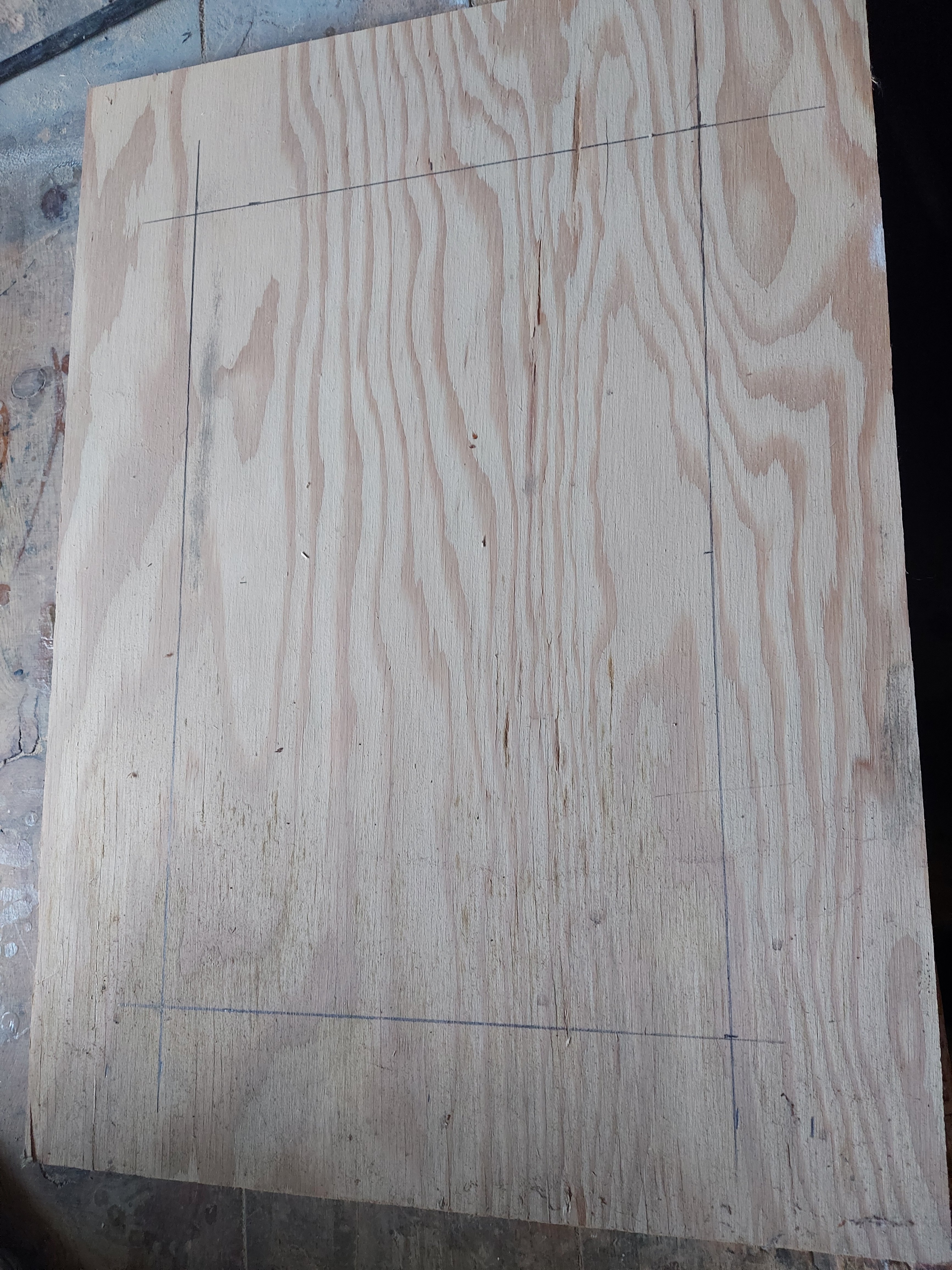
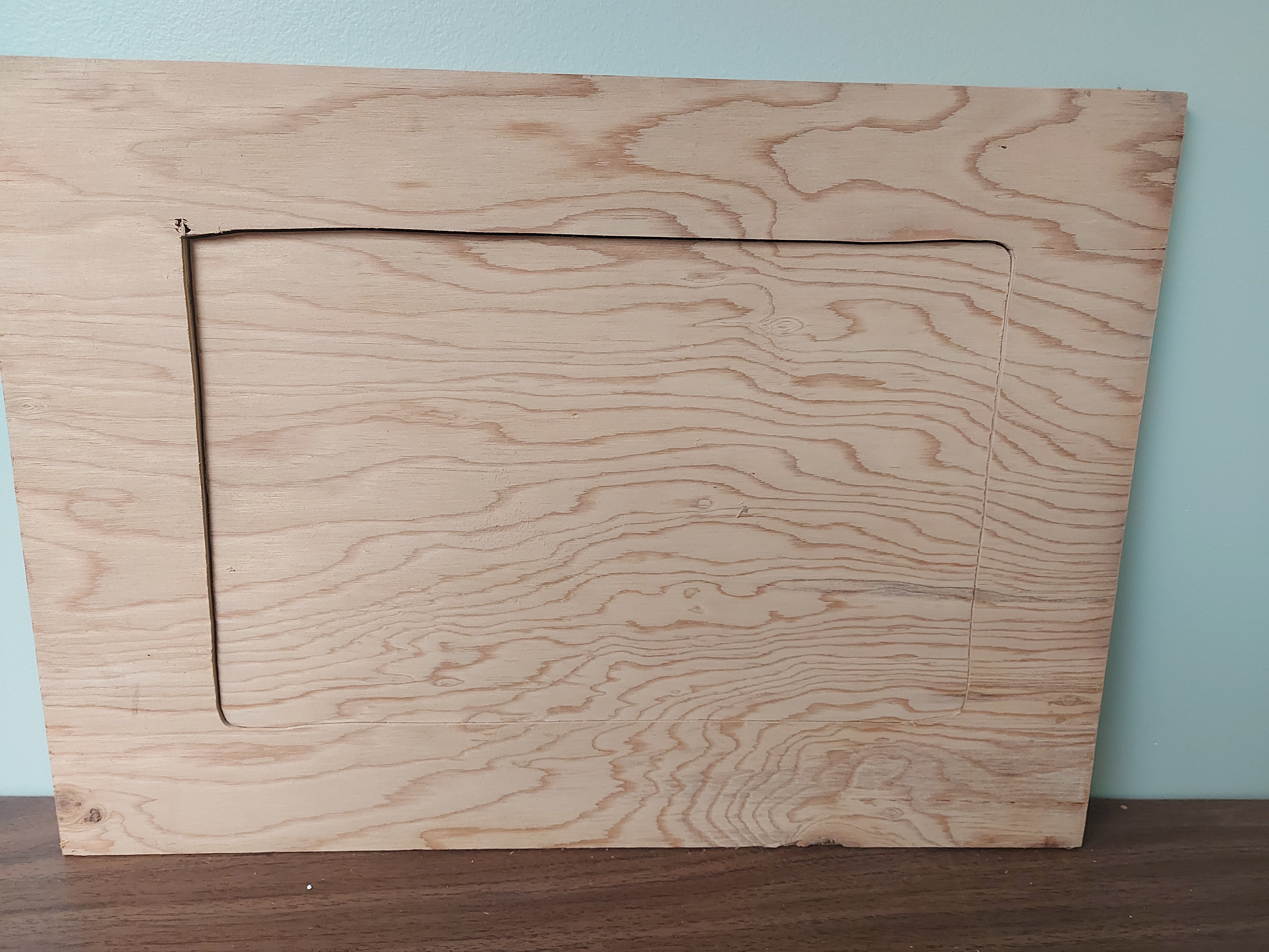
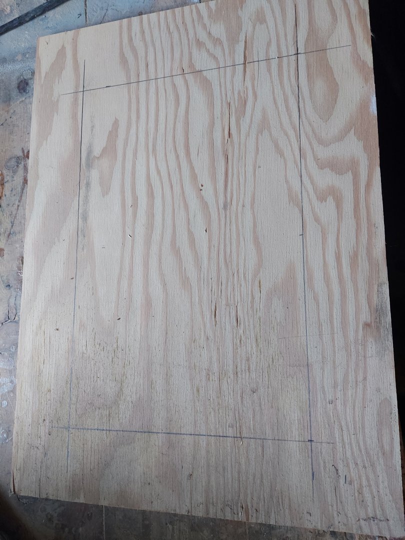
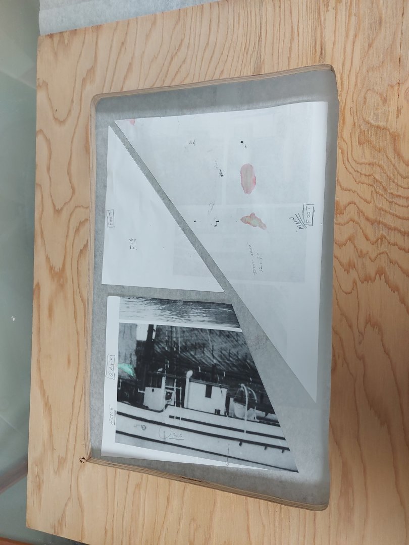
I have never made sails for models before, so the old dog will try to learn another new trick, mentored by David Antscherl and his Appendix to his Sphinx series of books. Thanks you very much in advance David! Silkspan is proving very hard to come by, so I can't say enough good things about people in the modelling fraternity who open themselves and their stashes to help those in need! Needless to say, like my sailor figure, I was saved by a fellow modeller who kindly donated enough Silkspan for my St. Roch... there may even be scraps left over for lifeboat covers! My sails will be furled, to hide my inevitable mistakes as much as giving a clear view of the decks, therefore I reduced the height of each sail about 30%, to allow for scale thickness of the material! The first picture shows the paper templates I made, sitting on the Silkspan. This lets me size the required sail-making frame... I marked the foot of each sail and oriented them in the same plane, so when it is time to mark the cloths that make up each sail it should be a matter of drawing the lines in parallel across the entire sheet. I hope! I found a suitable sized piece of plywood in my garage scrap lumber stash, and using measurements taken from the templates and allowing for the required overlap of the Silkspan onto the wood, I marked out the hole to cut, creating the frame and insert in one operation. A clearance hole and one pass with my scroll saw was all it took, then a bit of finishing with my palm sander. The cut is not perfectly square because the scroll saw throat is a bit smaller than the length of cut! The insert will support the Silkspan while it is being worked on, and the frame will hold it taut. Here is the frame checking for size on my templates. I flipped over the foresail template which reduces the amount of Silkspan needed. Next step is to start painting and tinting the Silkspan to look like canvas... David recommends mixing and thinning artists' tube acrylics, but this is expensive and will be almost all left over, so I am going to try my Tamiya acrylics on an offcut piece... my experience is that the paint will remain flexible after drying, so fingers crossed! If anyone has tried this I would love to know how it turned out! Thanks for looking in!

-
Thank you very much Steve, and Alan too! That means a lot... perhaps the old dog can learn a new trick! Regards, Bruce
-
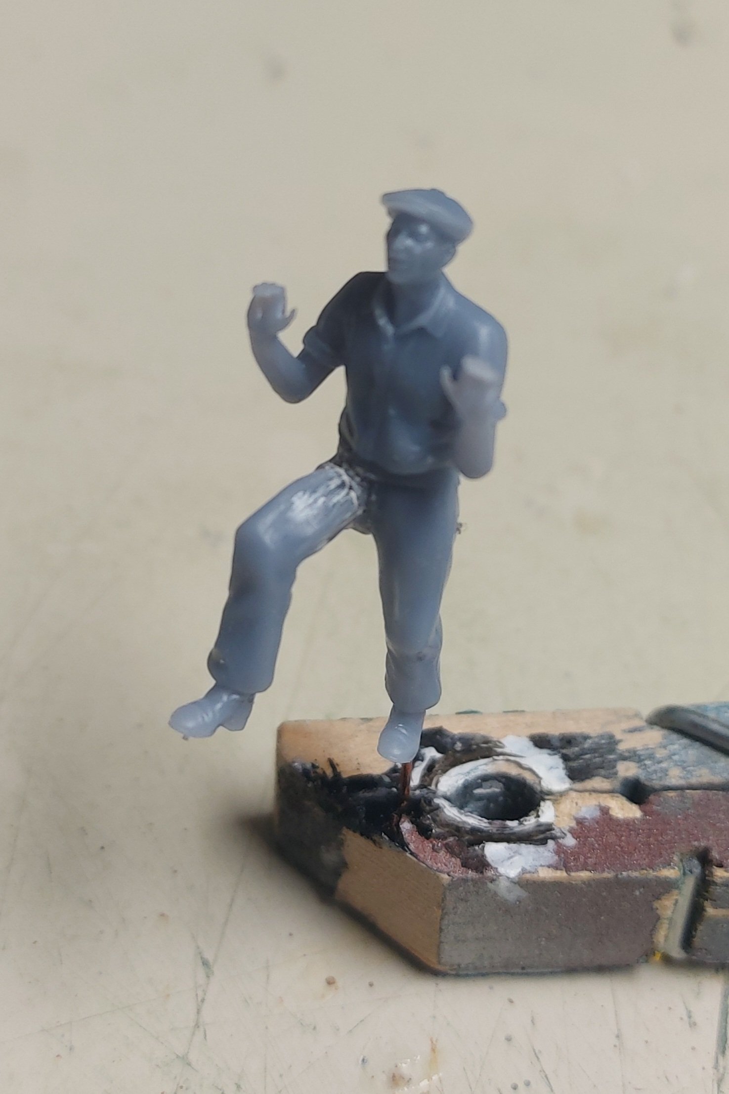
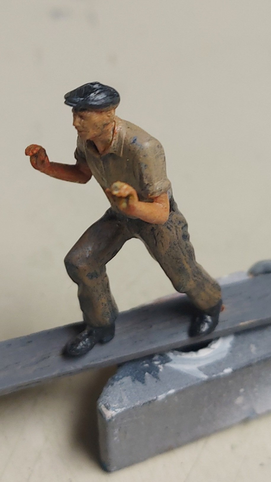
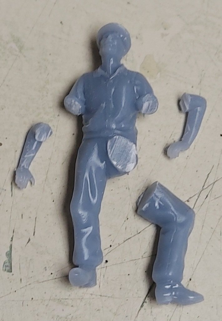
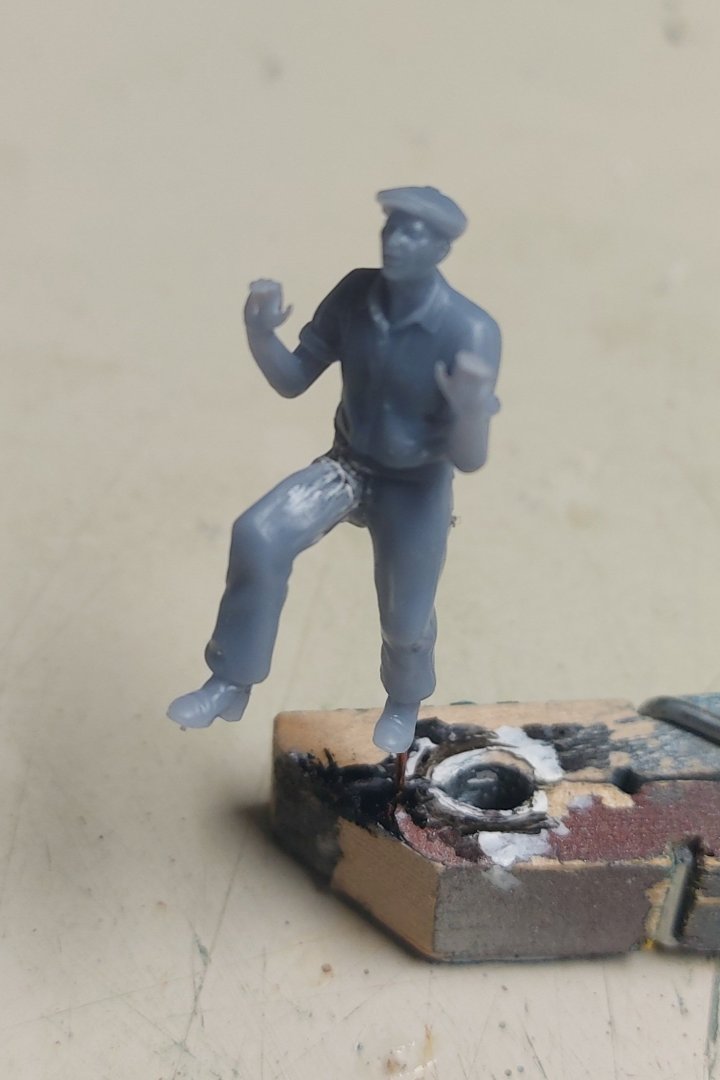
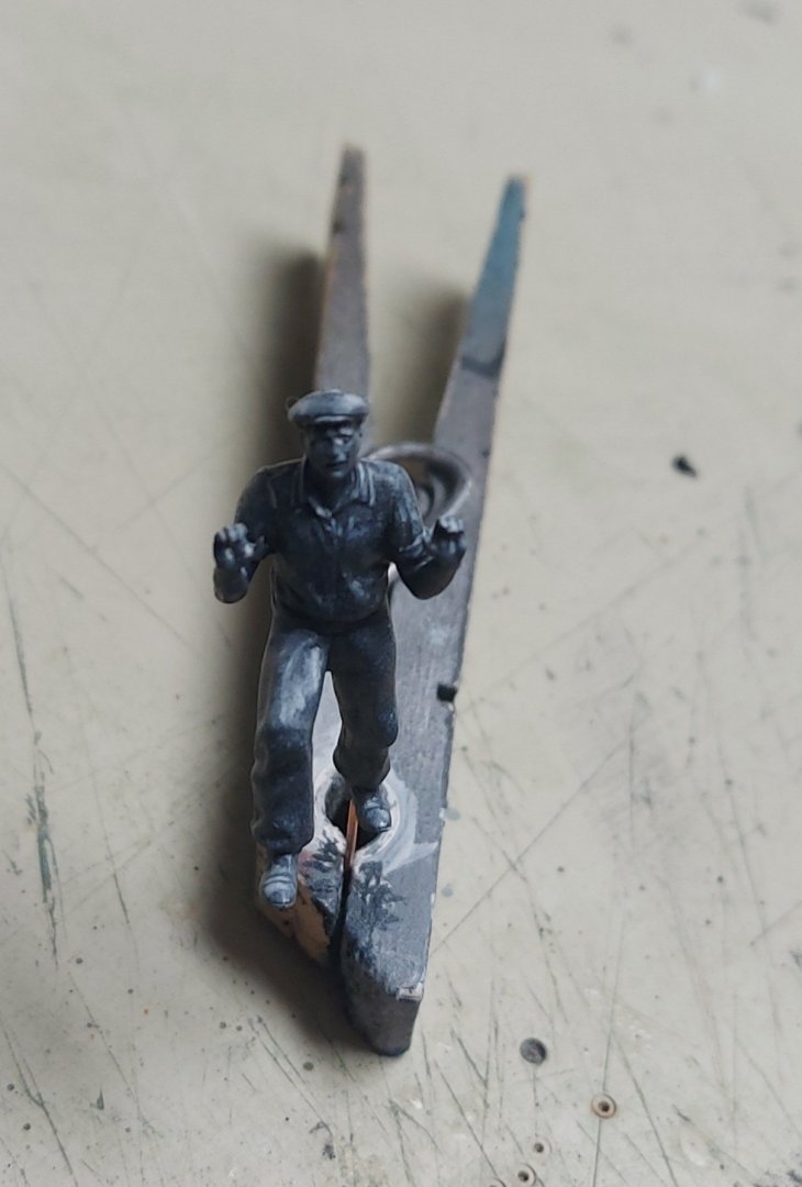
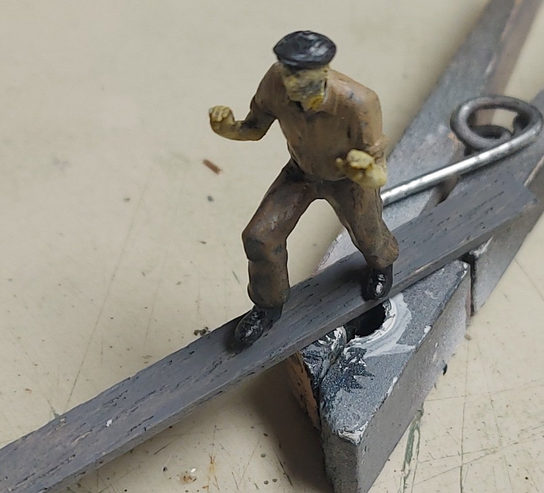
A while back I said I wanted to create a cargo handling scene involving a sailor, to give scale to the model. A friend of a friend on another modelling site knew a guy on thingiverse.com who 3D prints figures for model railroaders... he showed me a photo of the figure below that he prints in 1:160 (N scale trains), and which looked perfect for my scene! So the friend of the friend did one up for me in 1:48, and sliced the limbs off so it would lay flat, thereby saving about $15.00 in postage! Here it is, out of the envelope: And after assembly with CA glue, I drilled a hole up the leg for a wire to make handling the figure easier. It just needed a small smear of filler on the leg seam, the arms fit perfectly! I haven't painted figures in decades, staying away from them since my previous efforts all looked very cartoon-like. But now I know how to dry brush, and there is You-Tube! I used Tamiya acrylics, first priming him with semi-gloss black, then air brushing flat white from above to highlight details. Then I dry brushed various layers and colours to get the shading I wanted. I left his shoes and belt semi gloss black, adding a flat aluminum buckle and flat black cap. The pants and shirt are dark brown, followed by flat white then light brown on the shirt. Here I have posed him on the plank that he will walk across the open hold on, pushing his sling load of cargo... I dry brushed some flat yellow onto his face and arms, but he looked jaundiced, so I made a skin tone from red and yellow, which makes orange, followed by a drop of white to tone down the colour, and finally a drop of light brown... Here he is ready to install. I need to make the cargo, and the sailor may not get mounted until the main mast and cargo boom are installed, which may be a while... We'll see how it goes! I think this is not perfect but a far cry from the cartoon finishes my previous figures sported! Thanks everyone for looking in!

- 384 replies
-
- 13
-
-
-
Thank you Harvey... The sheet can be let out port or starboard depending which end of the traveller the block is up against. When the sheet is trimmed it is belayed to the cleat. Hope this helps! Bruce
-
Can't say for sure about Gjoa, but on St. Roch there is a cleat adjacent to the traveller for belaying the sheet. This cleat does not show up on kit plans... perhaps pictures from the Fram museum, or asking them on email, might help? Nice job on the sails, I hope mine turn out as nice! Regards, Bruce
-
The silkspan arrived today, so now I am off to make a sail making frame a-la Antscherl!

-
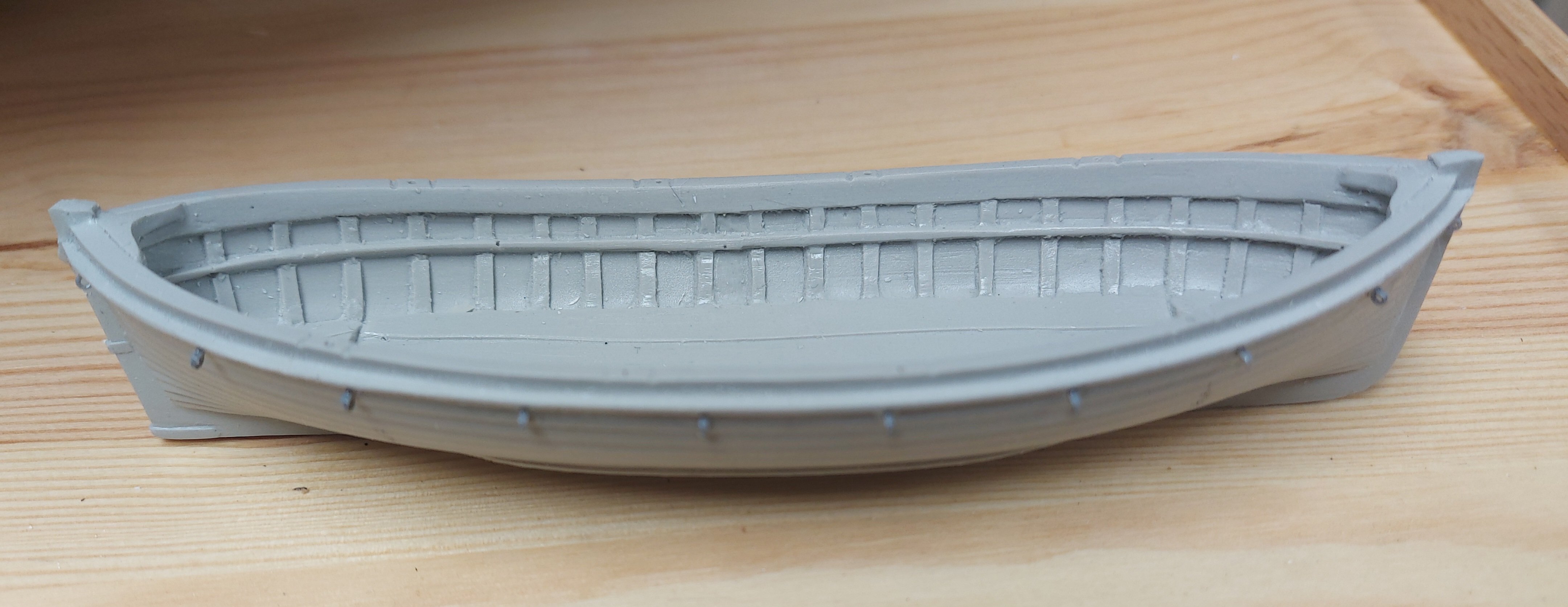
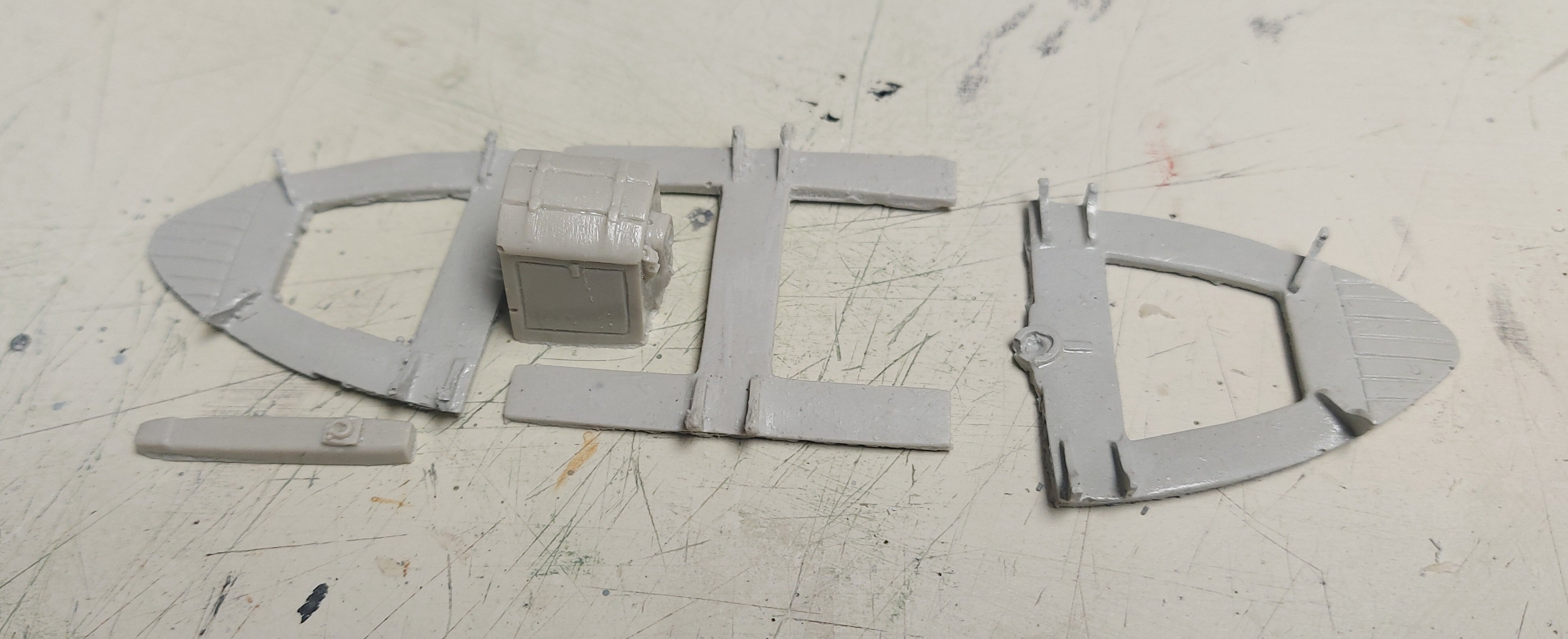
I thought folks might like to see the motorboat... so here it is, a much better quality casting similar to my aformemtioned RN dinghy, with a fully molded interior and separate parts for the motor housing and thwarts. I have cleaned up the flash and installed the rings holding the life rope around the outside. Despite having a better interior, I am still going to cover the motorboat. St. Roch's boat is under cover and I have no details on the correct interior details, especially the motor! Regards, Bruce