wglasford
-
Posts
40 -
Joined
-
Last visited
-
 SteveLarsen reacted to a post in a topic:
USS Missouri by wglasford - Trumpeter - 1/200 - PLASTIC
SteveLarsen reacted to a post in a topic:
USS Missouri by wglasford - Trumpeter - 1/200 - PLASTIC
-
schooner reacted to a post in a topic:
USS Missouri by wglasford - Trumpeter - 1/200 - PLASTIC
-
yvesvidal reacted to a post in a topic:
USS Missouri by wglasford - Trumpeter - 1/200 - PLASTIC
-
Canute reacted to a post in a topic:
USS Missouri by wglasford - Trumpeter - 1/200 - PLASTIC
-
king derelict reacted to a post in a topic:
USS Missouri by wglasford - Trumpeter - 1/200 - PLASTIC
-
Kenchington reacted to a post in a topic:
USS Missouri by wglasford - Trumpeter - 1/200 - PLASTIC
-
Force9 reacted to a post in a topic:
USS Missouri by wglasford - Trumpeter - 1/200 - PLASTIC
-
ccoyle reacted to a post in a topic:
USS Missouri by wglasford - Trumpeter - 1/200 - PLASTIC
-
scrubbyj427 reacted to a post in a topic:
USS Missouri by wglasford - Trumpeter - 1/200 - PLASTIC
-
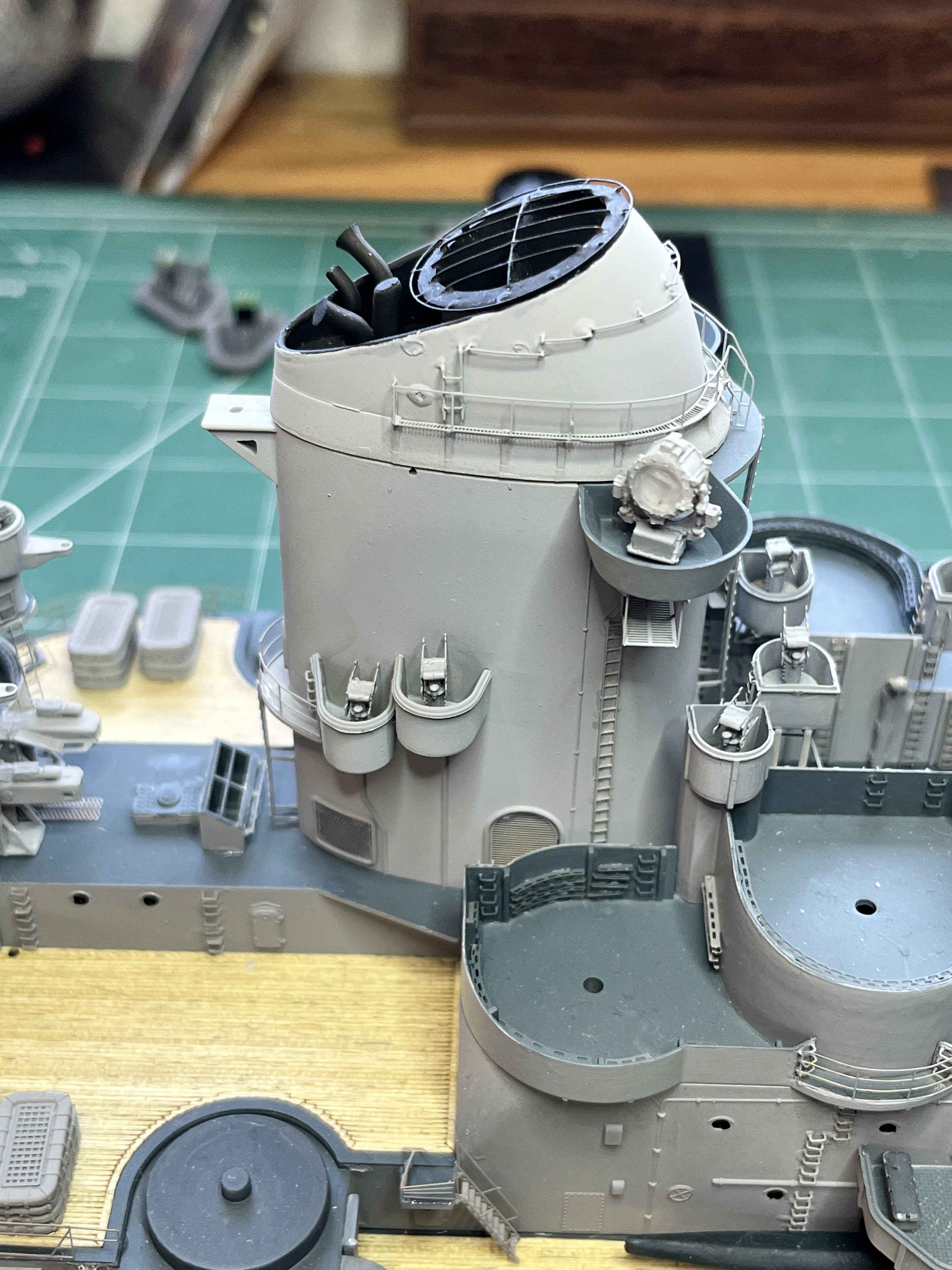
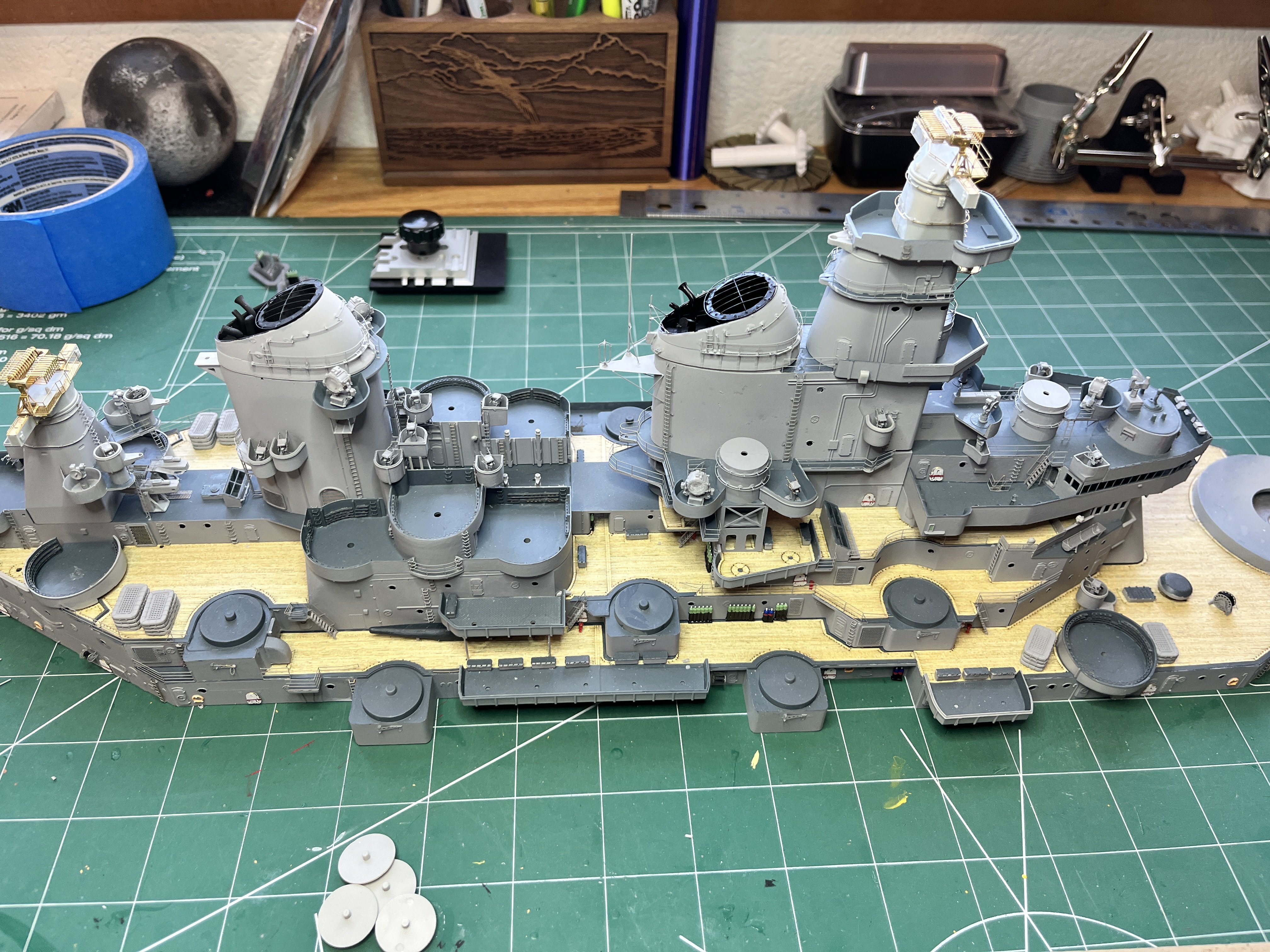
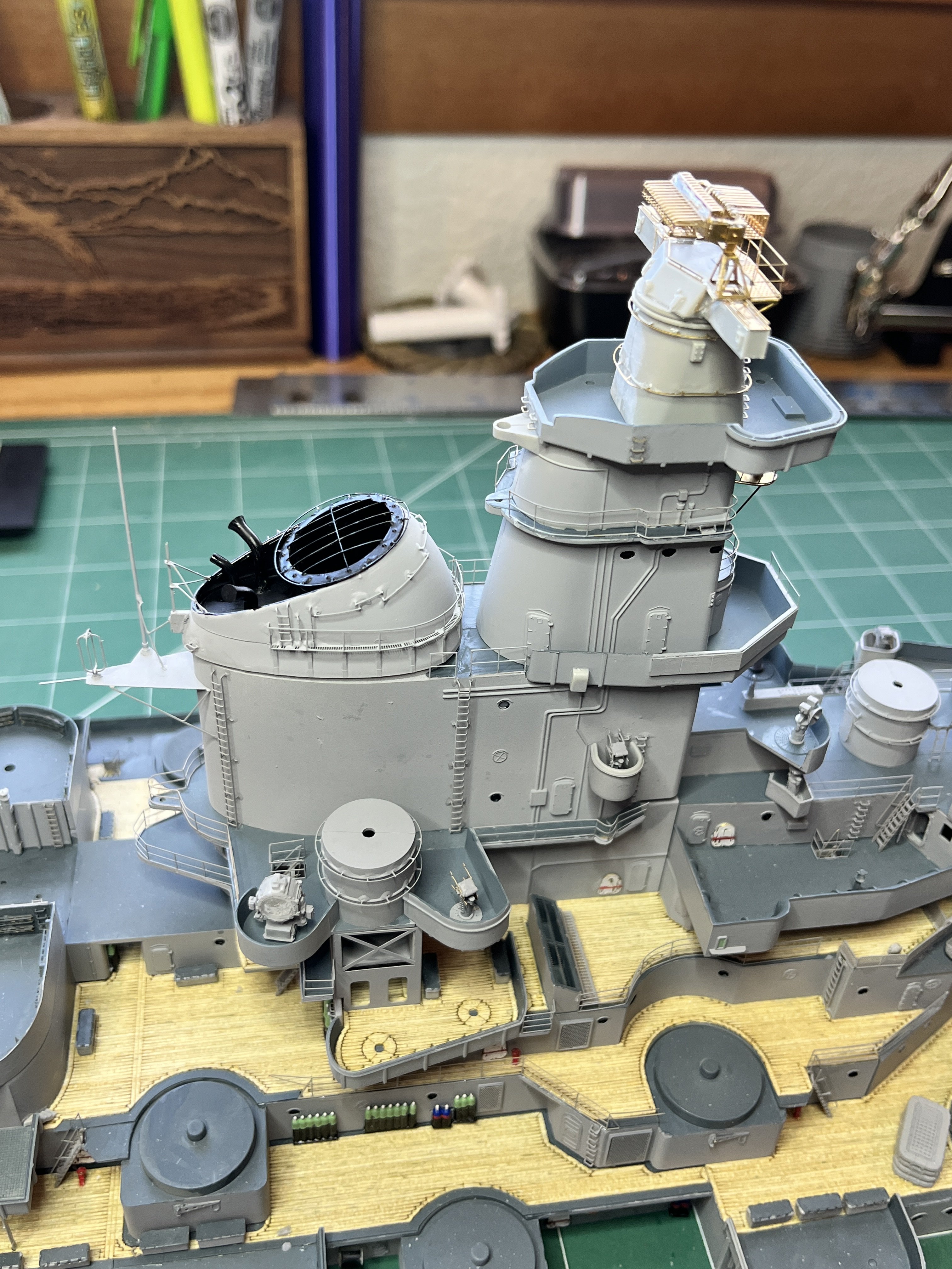
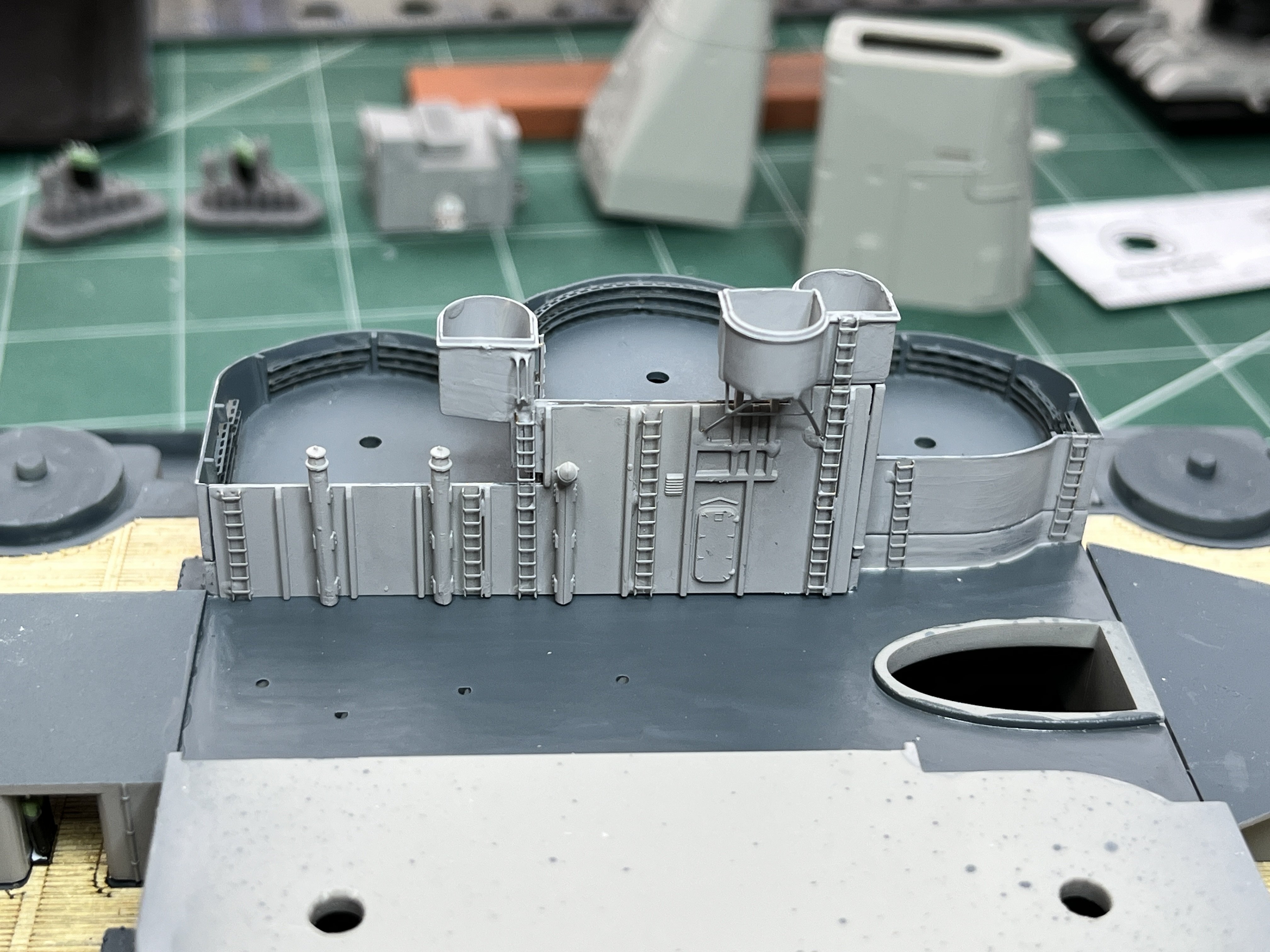
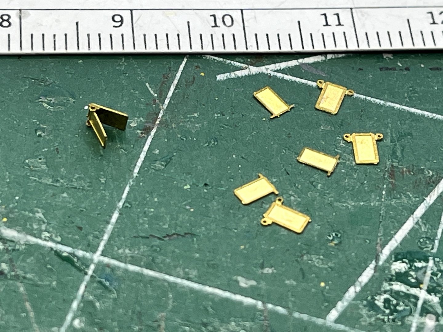
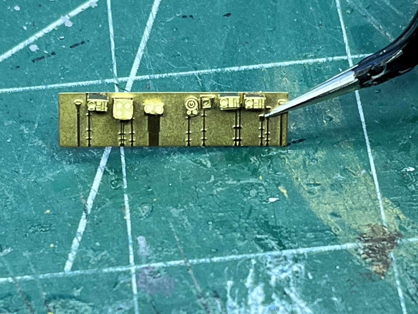
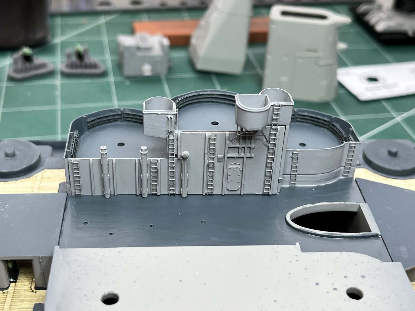
Back to working on this model. Took a break to complete all the other mostly completed models and even created a 3D printed model of The Big Carl crane. This is now the only model I have in-progress, a final push to get this one complete. Continuing to work my way up the superstructure, creating the smoke stacks and main stack. Things have gone from mostly plastic parts to mostly photo etch. And the parts are getting really small and fragile. These little hatches are 2x3mm in size. The ends of the tweezers are feeling really big. Here are pictures of the forward tower/smoke stack and the aft smoke stack. They are not glued on yet because more parts need to go on and some of it still needs to be painted. I'm holding off on adding the more delicate parts.


-
yvesvidal reacted to a post in a topic:
USS Missouri by wglasford - Trumpeter - 1/200 - PLASTIC
-
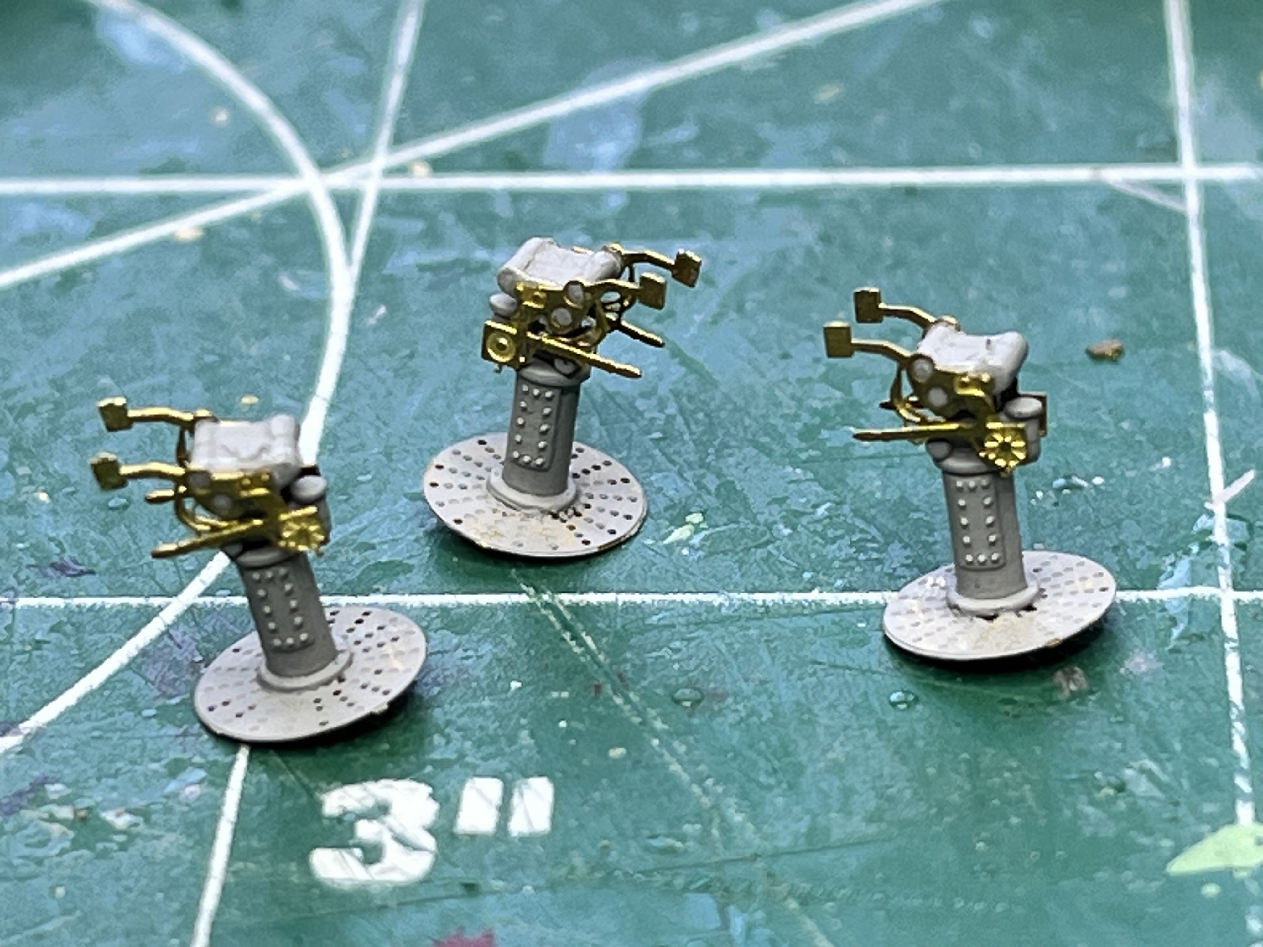
The Bofor directors, MK51, needed some side handles. The Pontos instructions showed them in various pictures but never identified the numbers. I found them, they are 751 and 752. The round perforated base plates are Eduard parts. This is the side handles on before painting them.

-
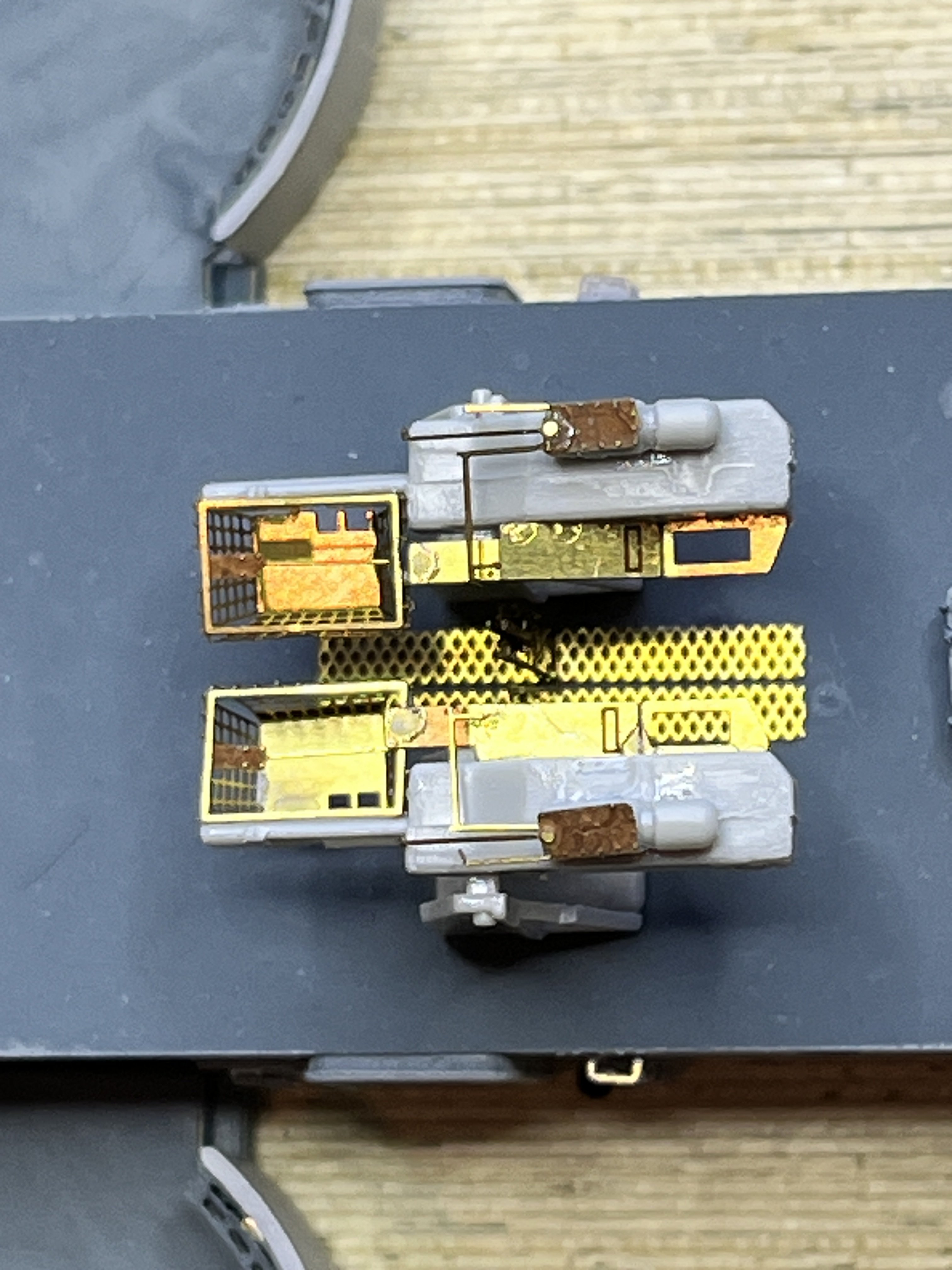
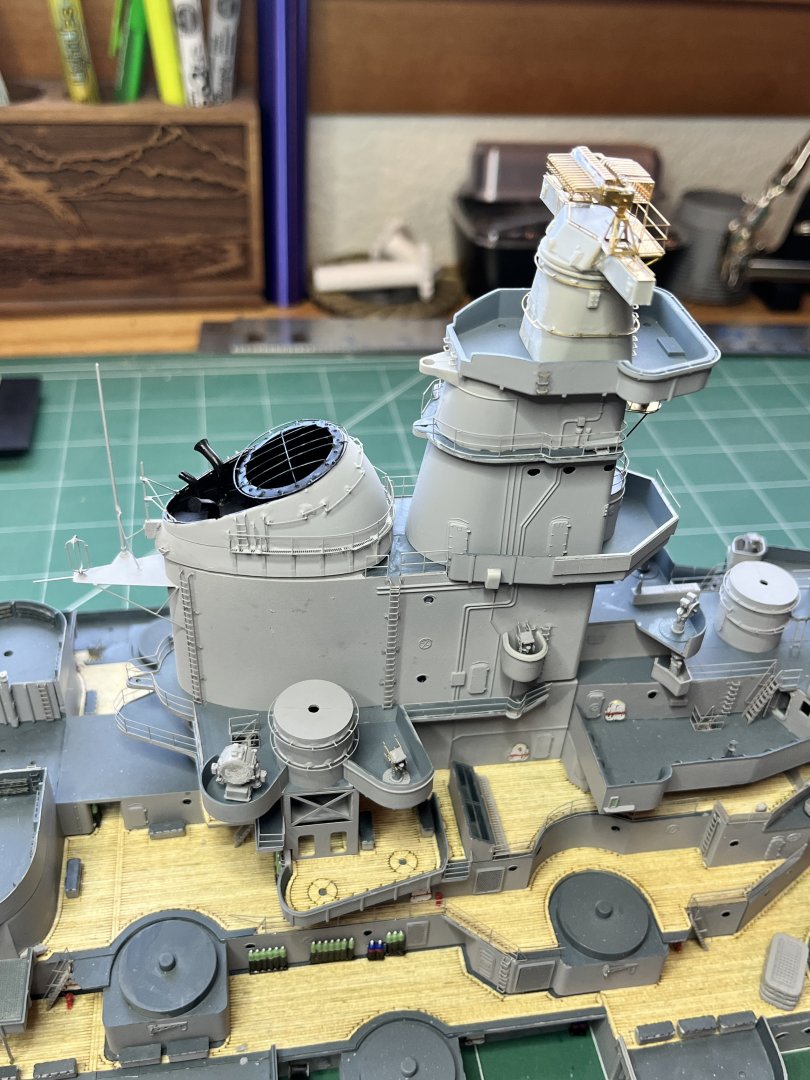
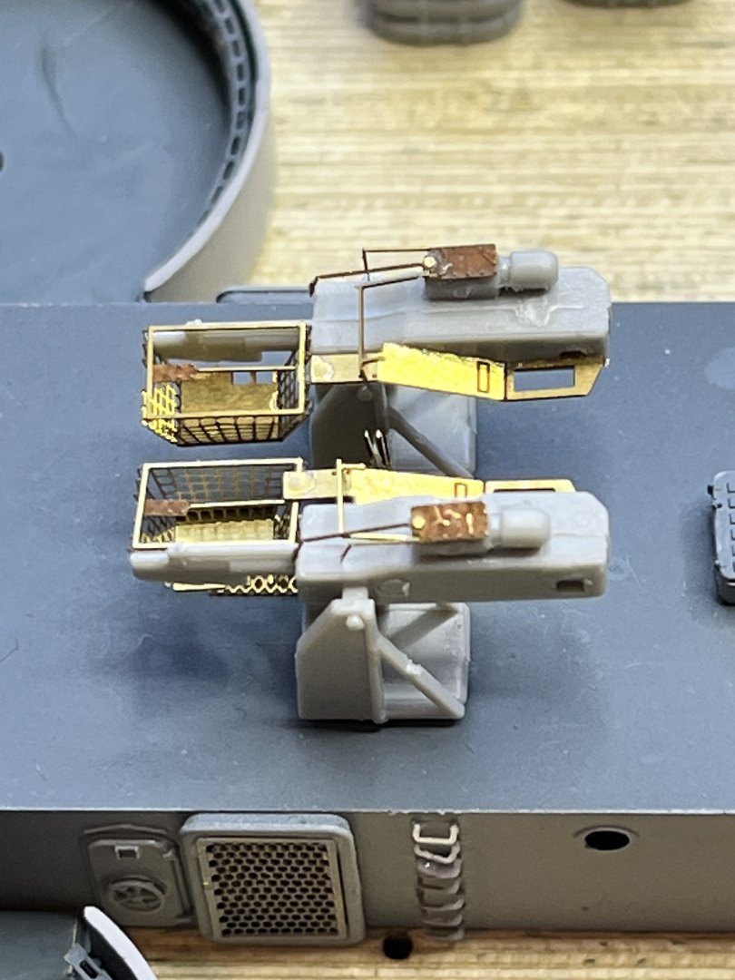
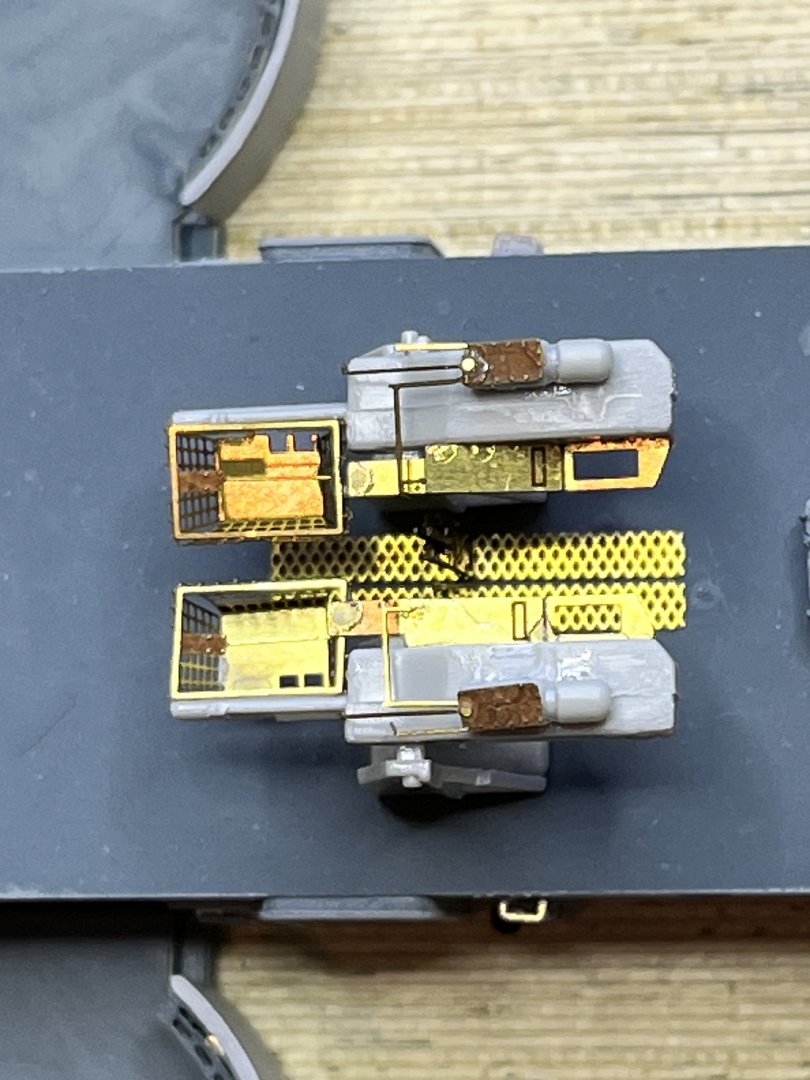
The Eduard parts come through again. Here are the 5" twin loading machines. Pontos ignore these. Notice on the drawing from The Floating Drydock that the loaders are mirror images of each other. The Eduard parts agree with this. Unfortunately the plastic kit parts are not mirror images so I had to cut off tabs and make do. Here are the loaders set into place before painting. Notice that there are also curved rails that are not set in place yet.
-
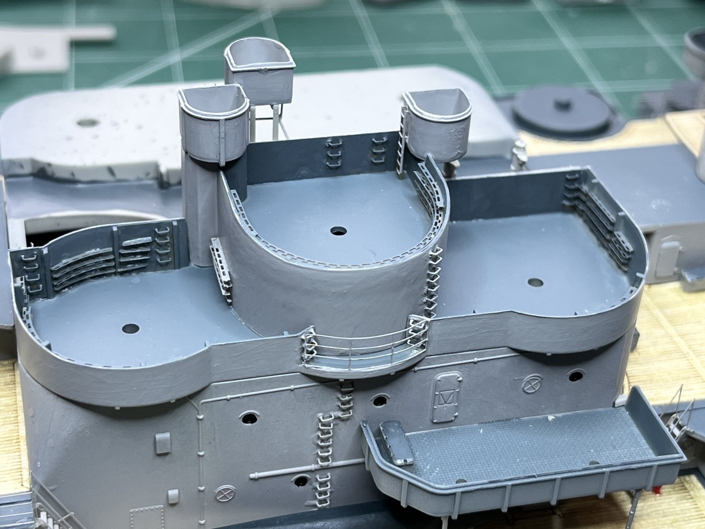
The bridge structure is now mostly complete except for the spotlight, the M37 director and the antennas. I need to figure out how to construct the antenna outrigger attachment points. The antennas will be fine black thread that goes up to the underside of the air defense station level. The outriggers need to be really small and thin, maybe some of the leftover brass etching. They will go on the outsides of the bridge in two places down to the conning tower, both sides of the walkway out to the spotlight, attached to the side railing where those side wall steps to nowhere go and to either side of the cable trunk that sits on top of the platform the has the two M56 directors.

-
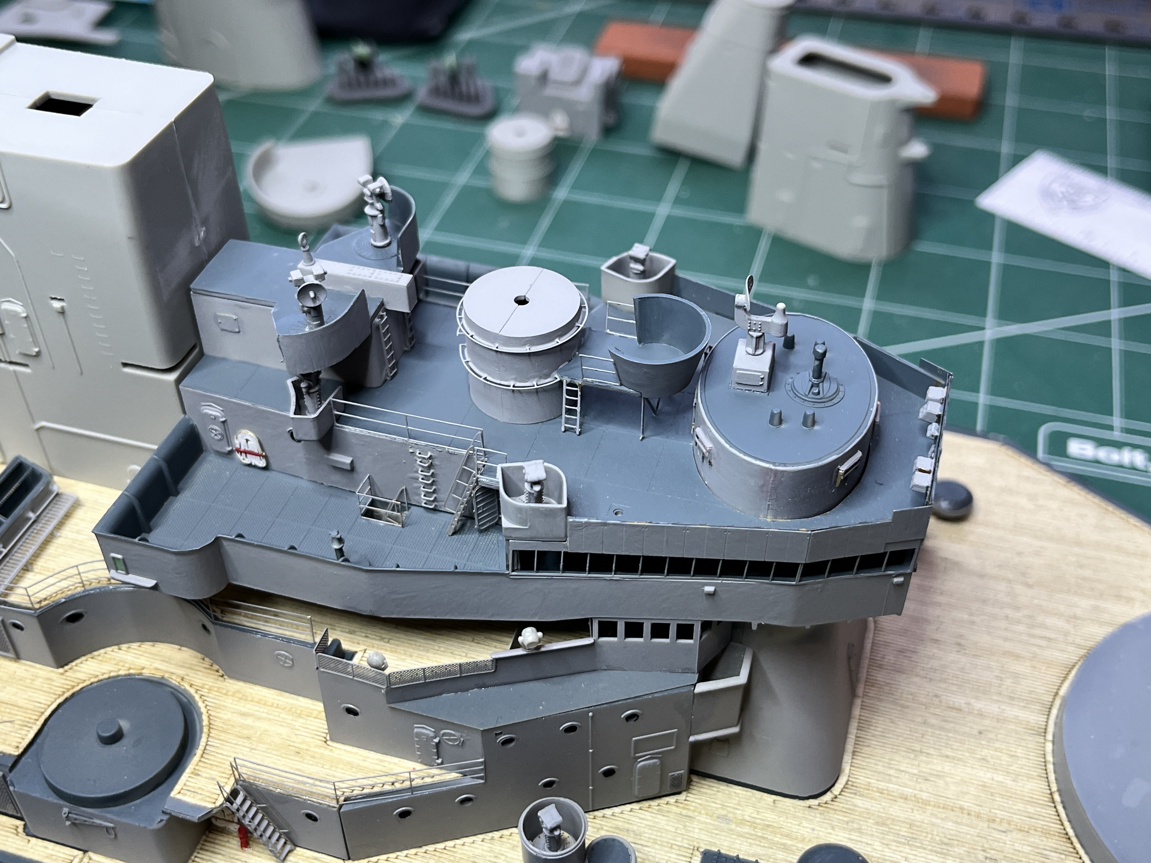
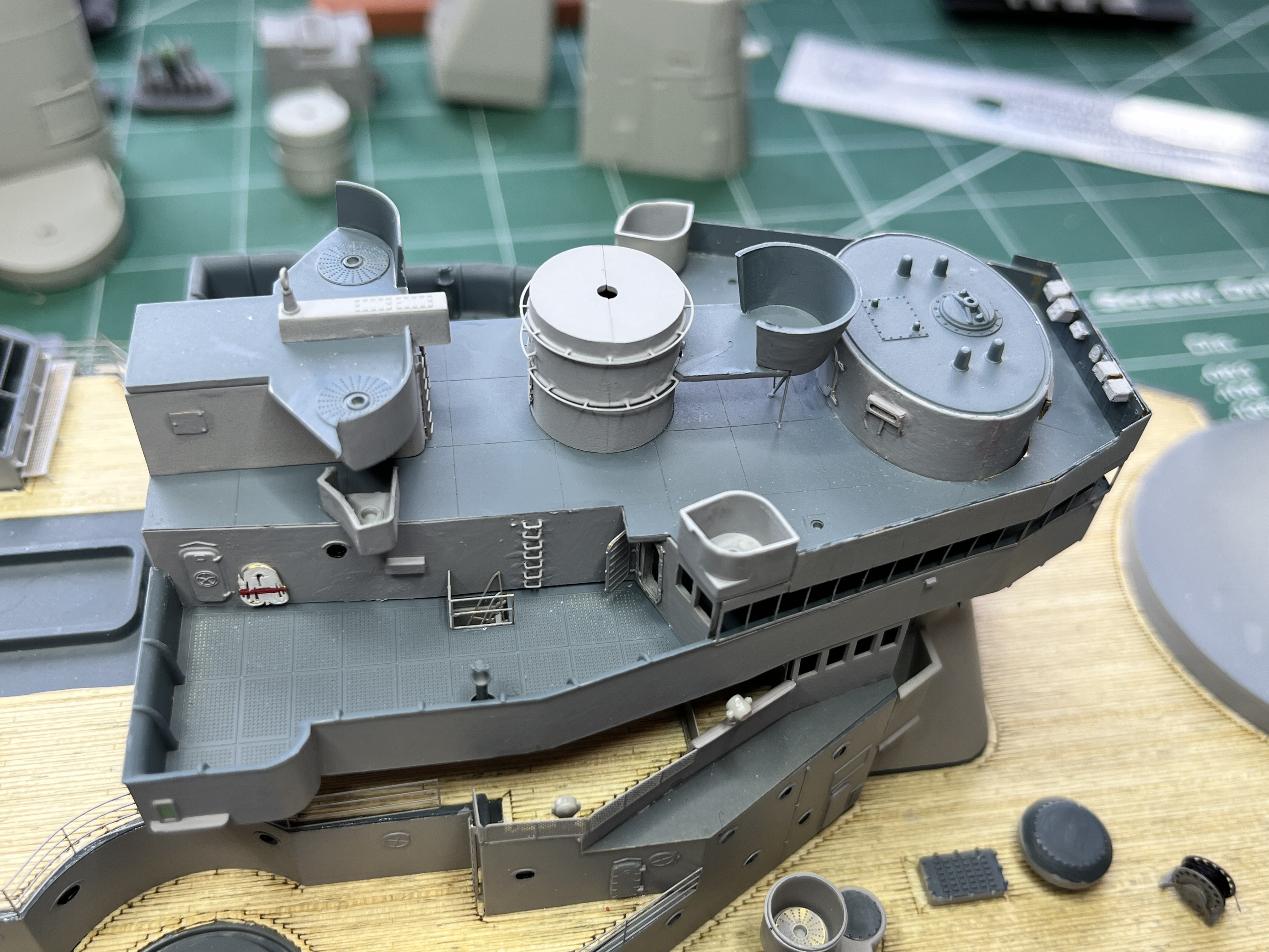
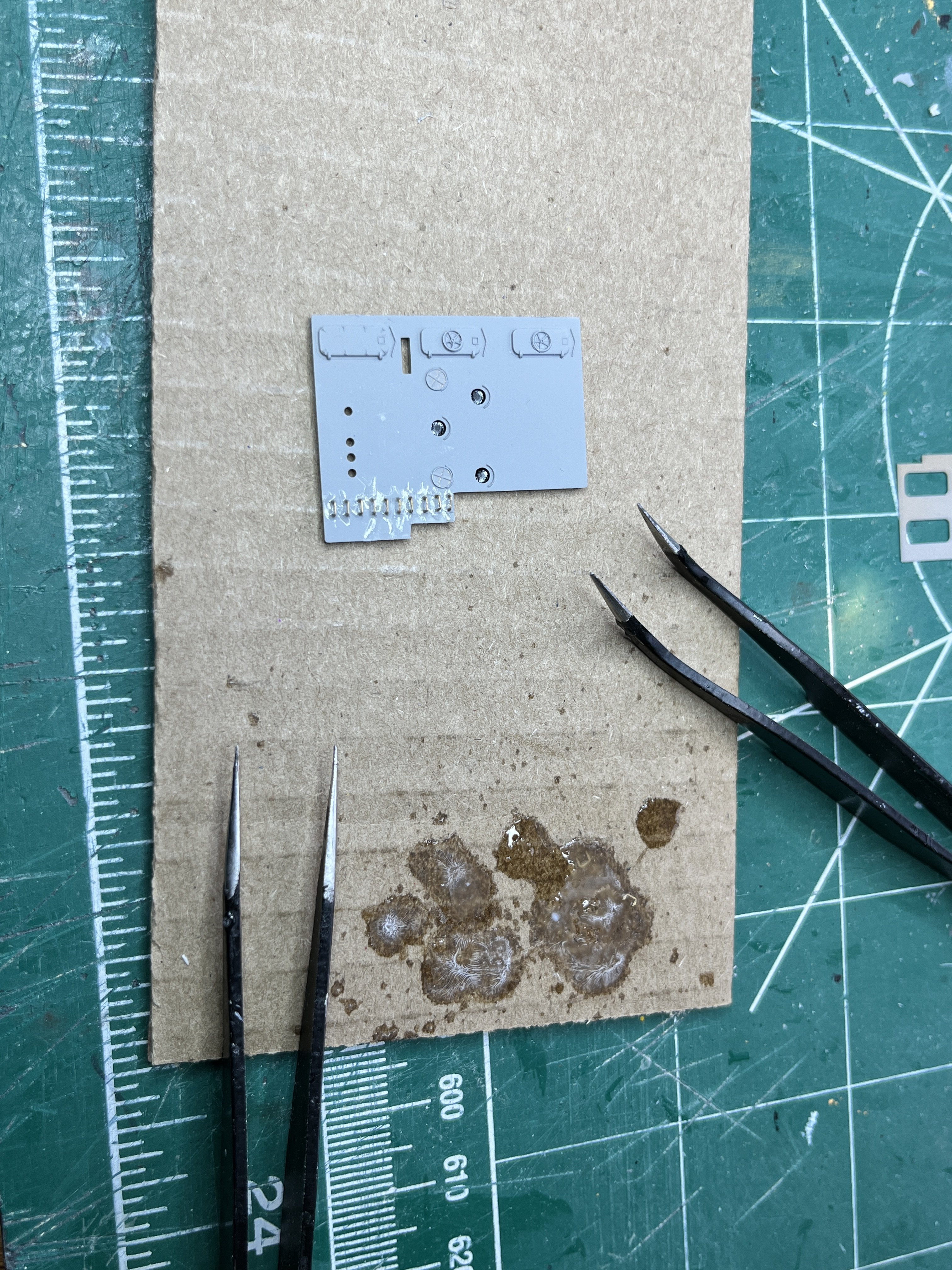
The pilot house level is coming together. Every time I look there are more parts to add. The front control boxes are some of the smallest parts yet. That one little part is 1x1mm. This part is going to be interesting to paint. And here is the pilot house level mostly complete. The further up I go there are fewer plastic parts and many more Pontos brass parts. On top of where the MK56 Directors will go there are round platforms with perforated holes that came from the Edward kit. The Eduard parts have proven to be a good addition the Pontos kit.


-
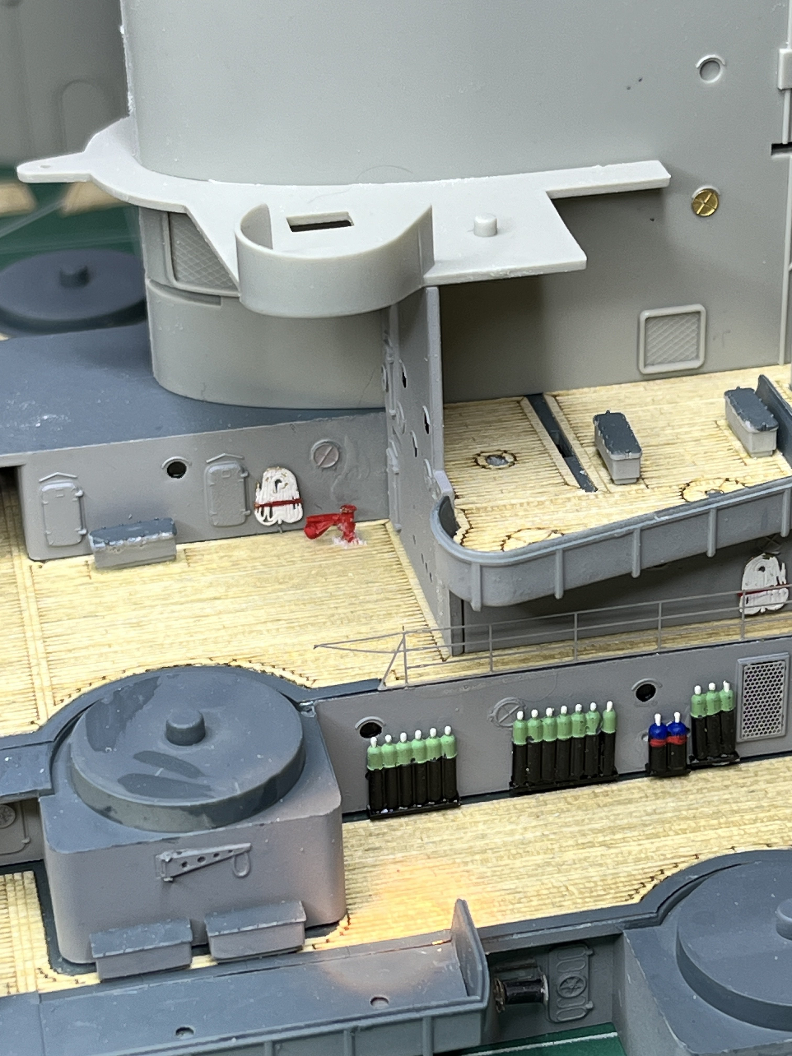
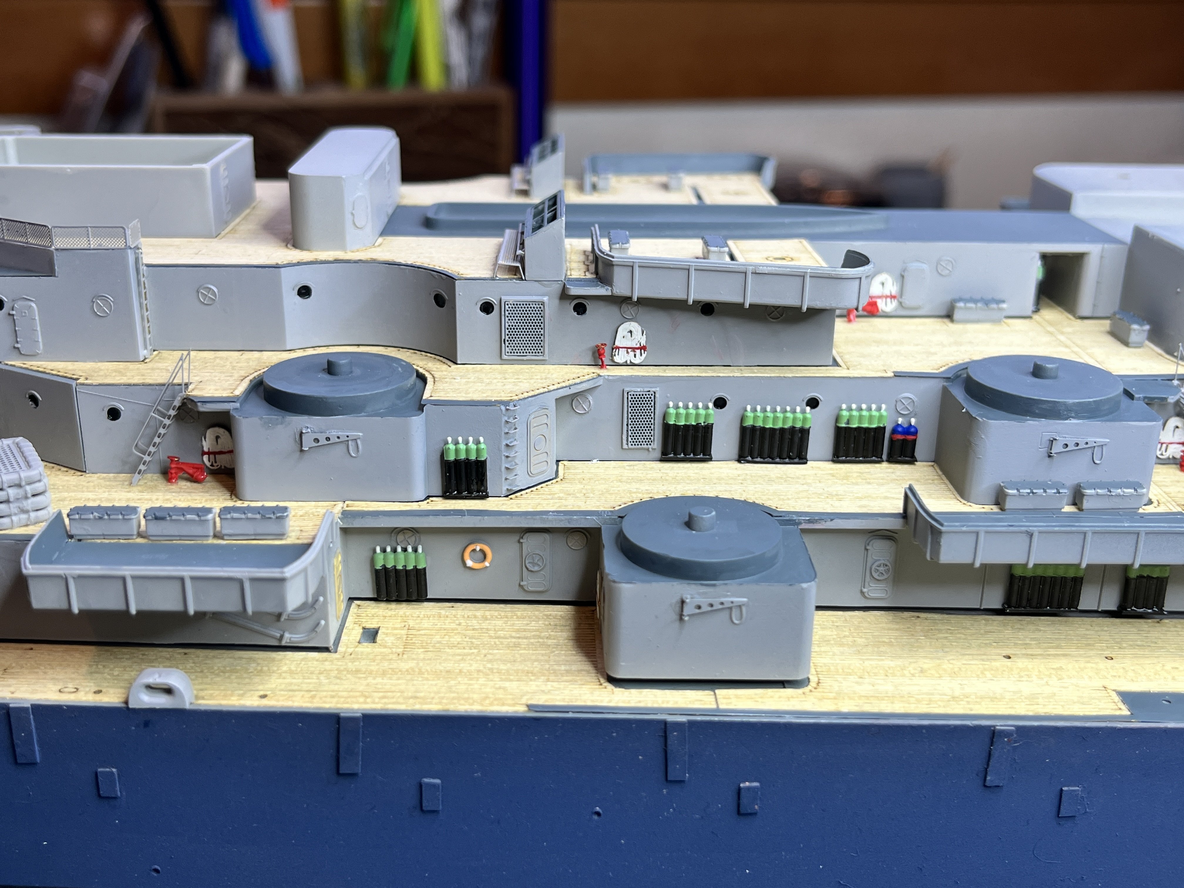
There are center bofors, 3 per side. Lots of small parts. One side is complete and set in place for now except for some final painting.
-
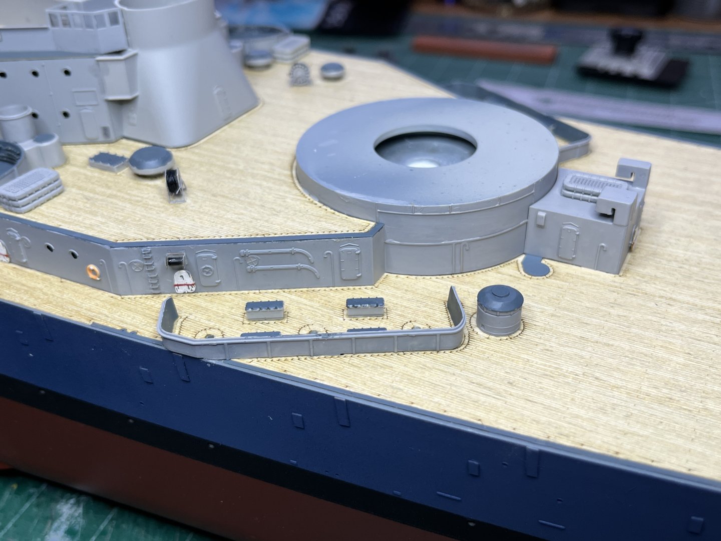
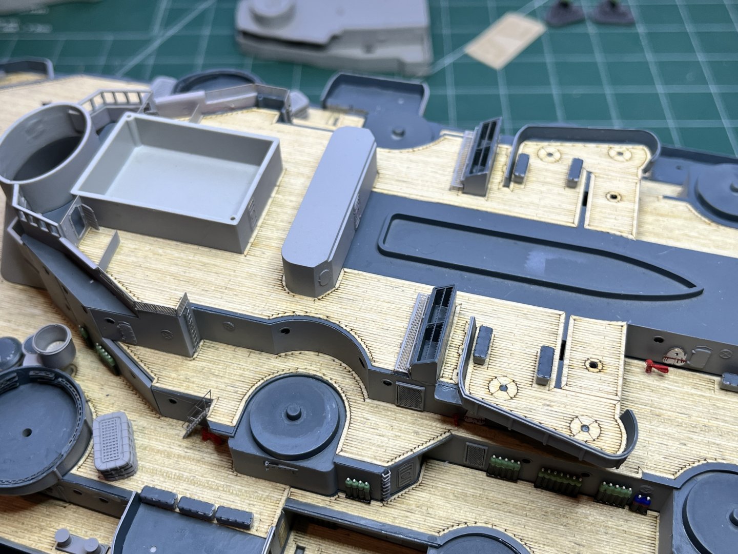
Here is the final wooden decking in place. The forward tower is just set in place for now, not yet painted.
-
There are people out there building this model that complain about the front tower not fitting down solidly due to the structure that the M37 director sits on being too tall. I got worried about this and figured it is better to discover the problem early when there are more fix options so I test fitted the long wall followed by the forward tower with the pilot house level platform set in place, the one that holds the search light, M37 and M51 directors. Everything fits in place exactly as it should. I'm not sure if Trumpeter identified and fixed the problem or if there is some gotcha still lurking out there that I have not run across yet. I will keep test fitting as I go to make sure this does not become a problem.

-
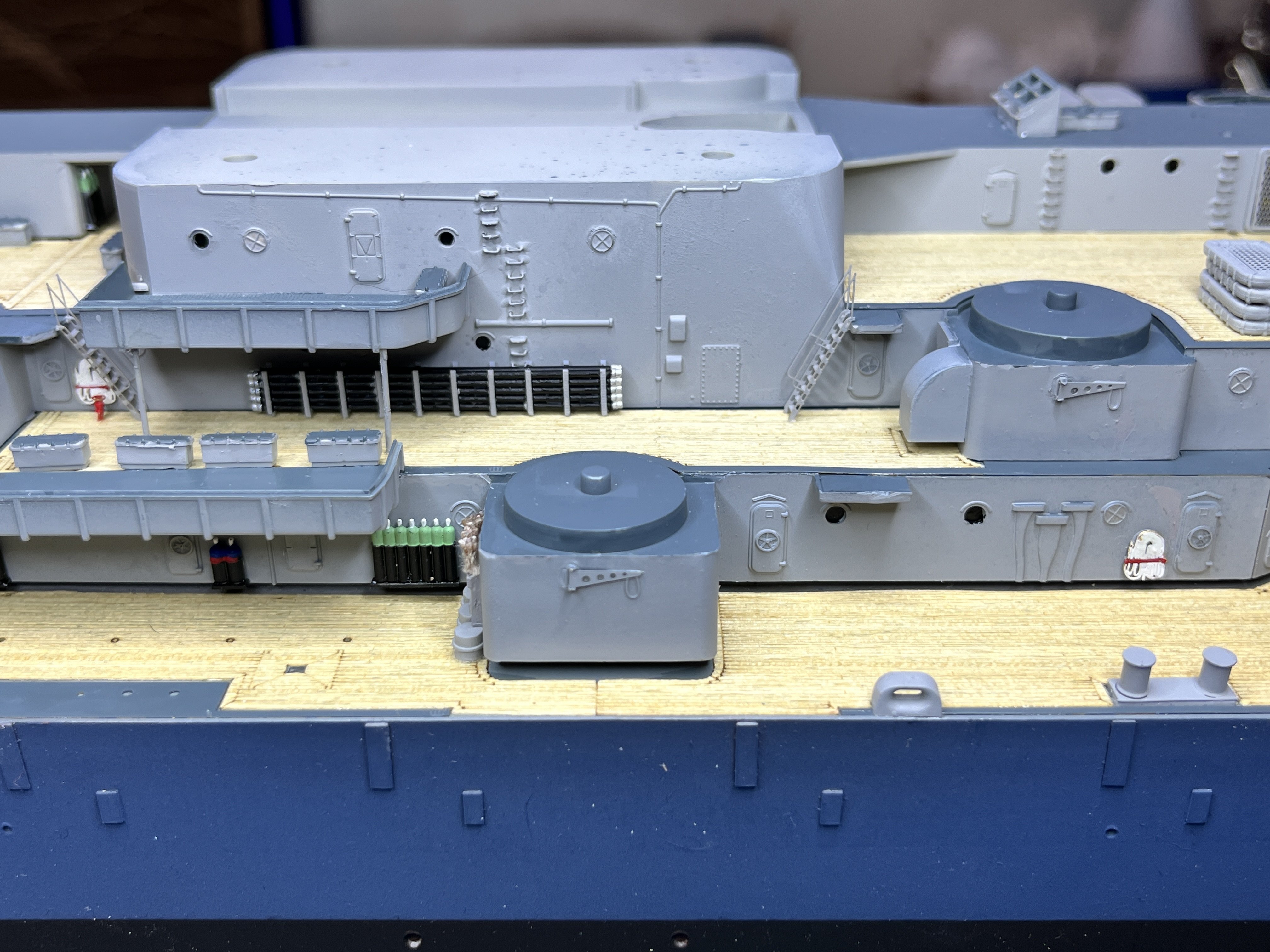
There are so many little ladder rungs to glue on. I have finally settled into what works best for me. I use two tweezers. First I use the angled tweezers which I call the dry tweezers to pick up the next rung and set it in place. Then I press the rung into place with the end of my thumb nail. With the rung dry fitted I use an end of the straight tweezers which I call the wet tweezers to grab a small amount of CA and place that on one end of the rung. It gets really frustrating if the dry tweezers get any glue on them. In this case dry off the tweezers and use the back of an exacto knife to scrape off any glue residue. It also helps to periodically scrape the glue off the wet tweezers.

-
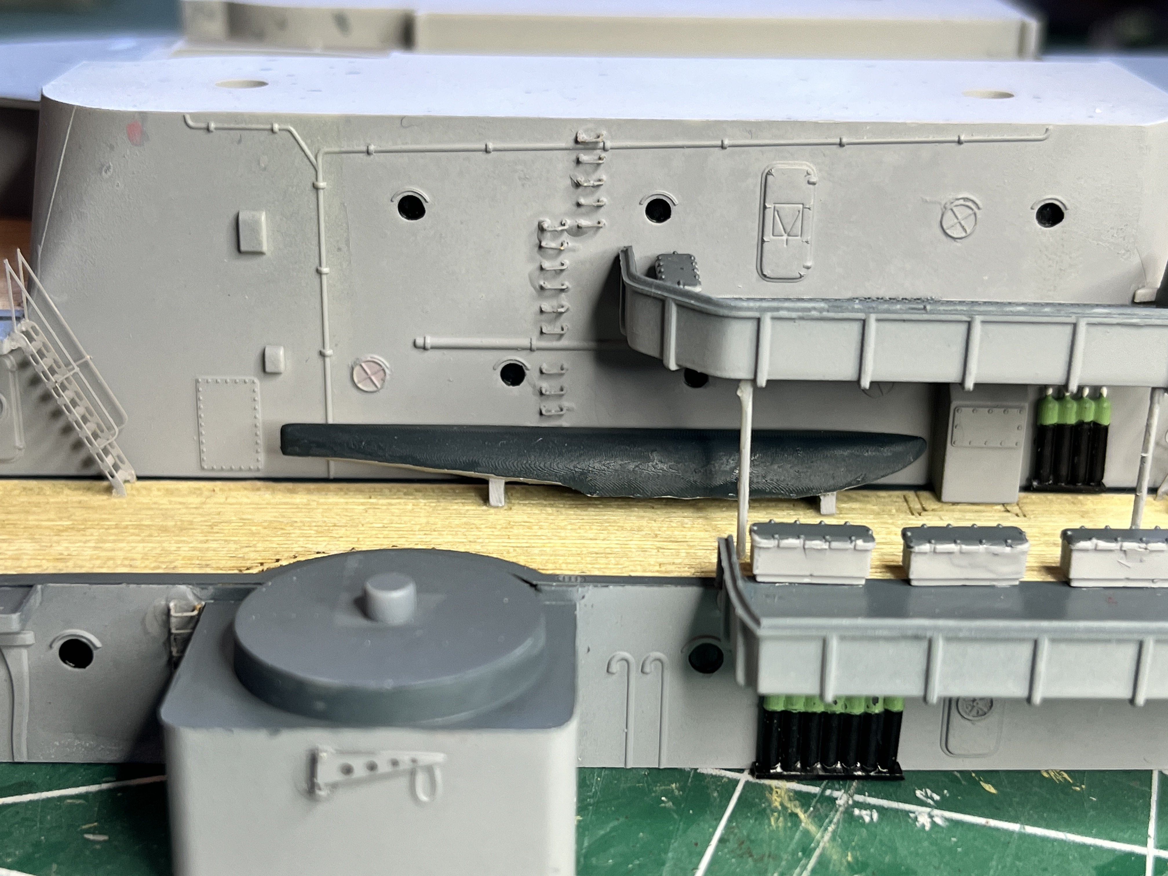
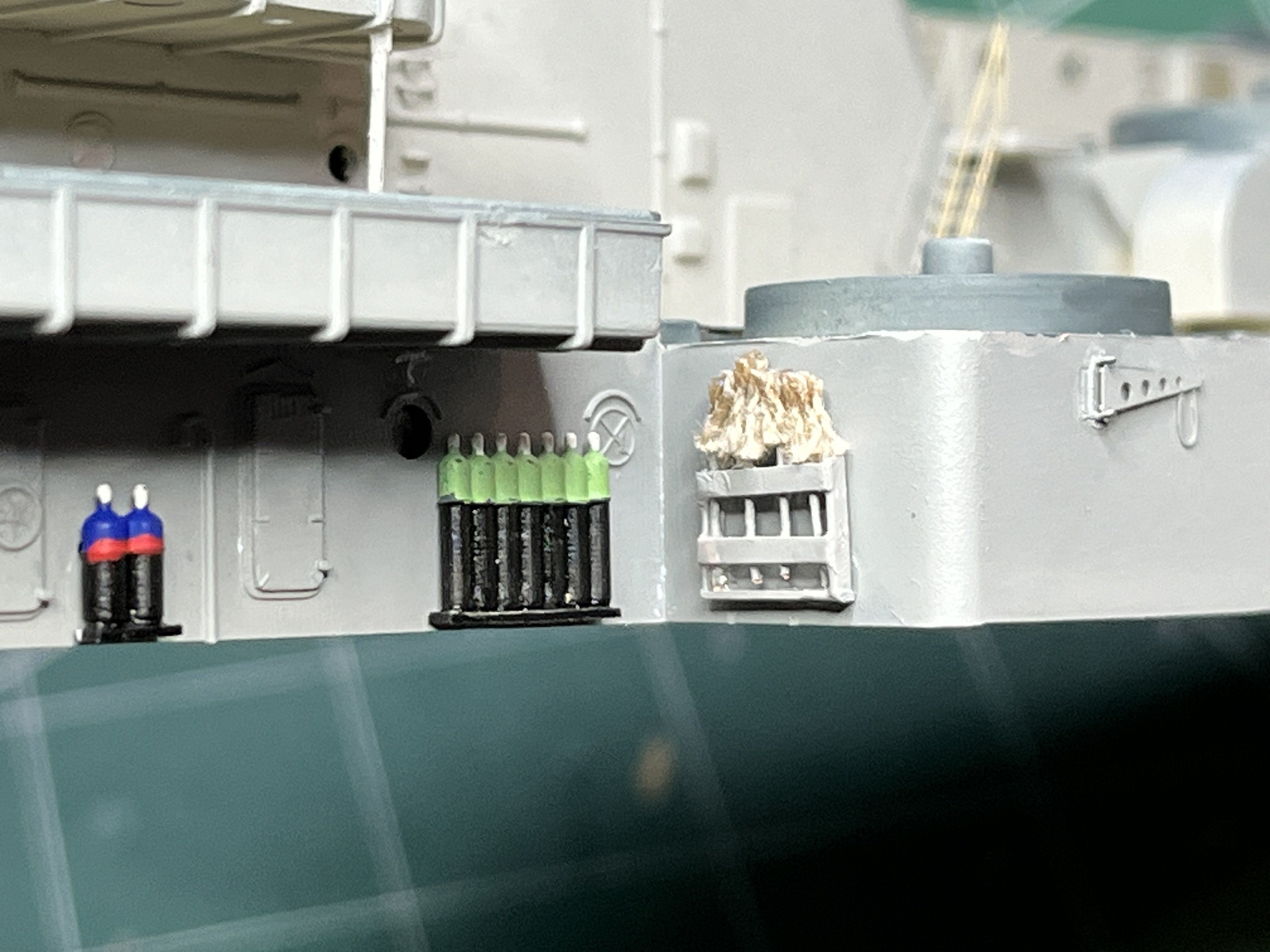
On the side of the navigation bridge level at the back corners there are little structures The Floating Drydock plans call "side running lights". I assume these are the navigation lights so starboard = green and port = red.

-
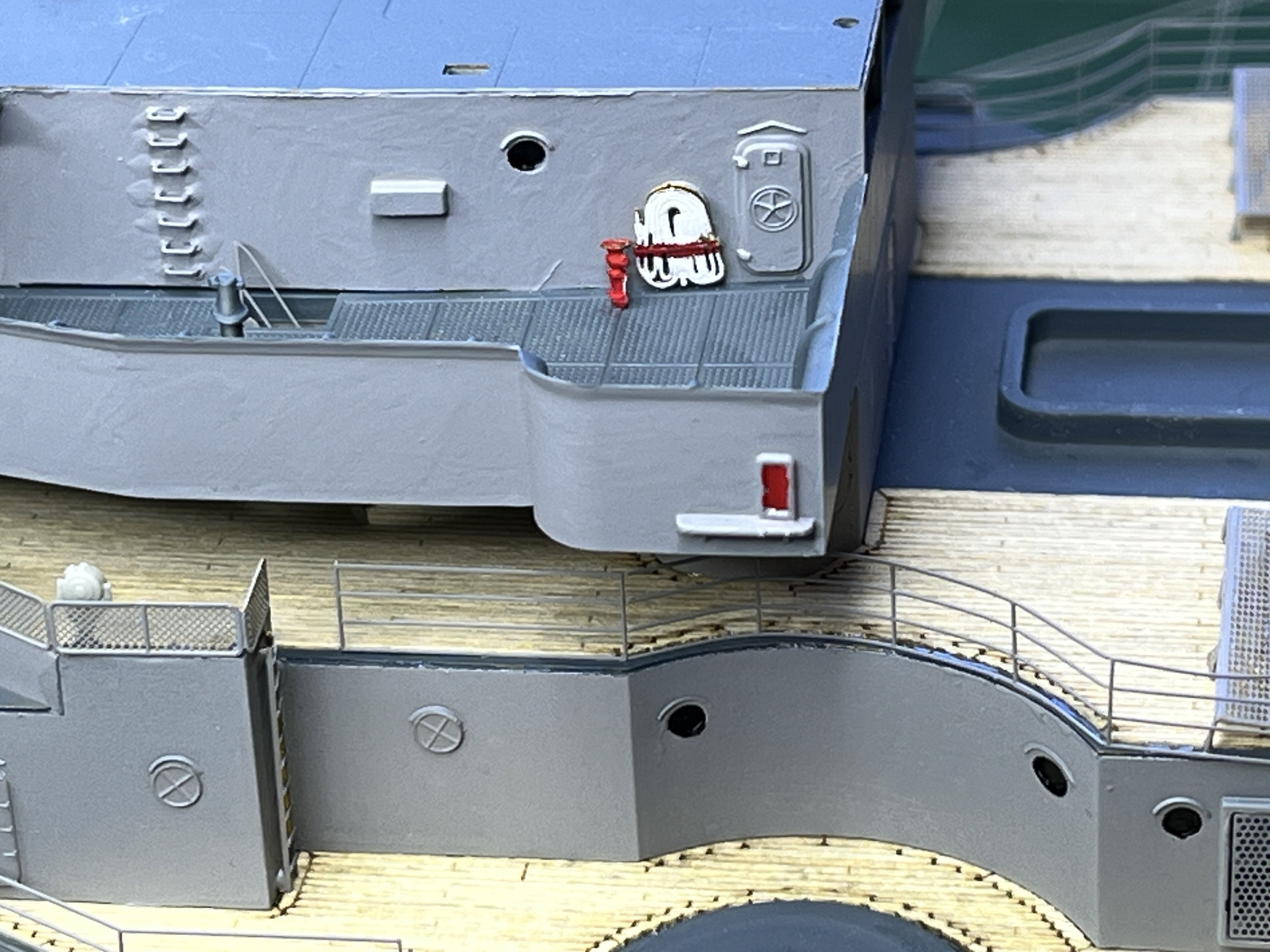
I had the mops in the wrong location. They should be a frame 108, on the backside looking forward.
-
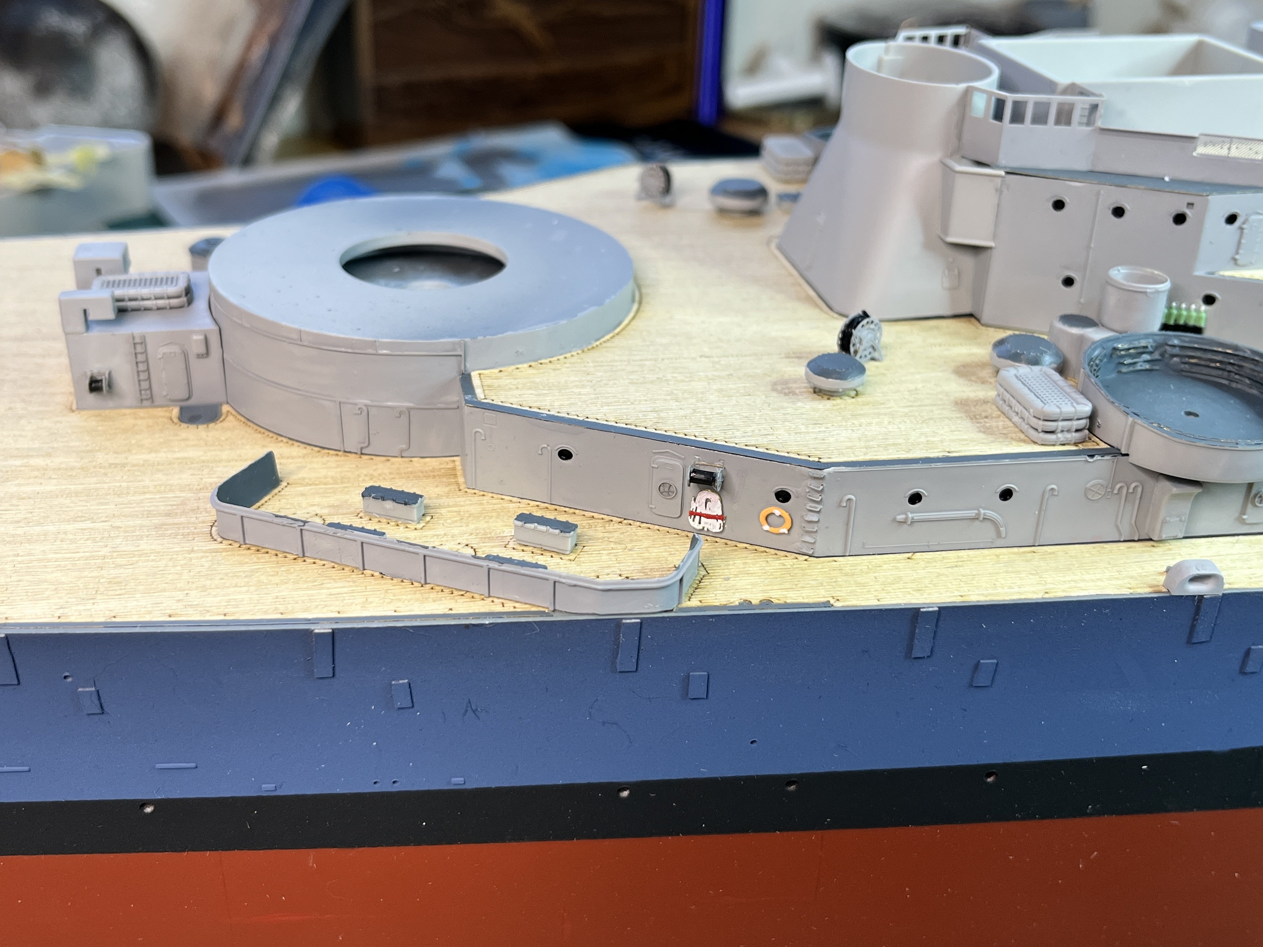
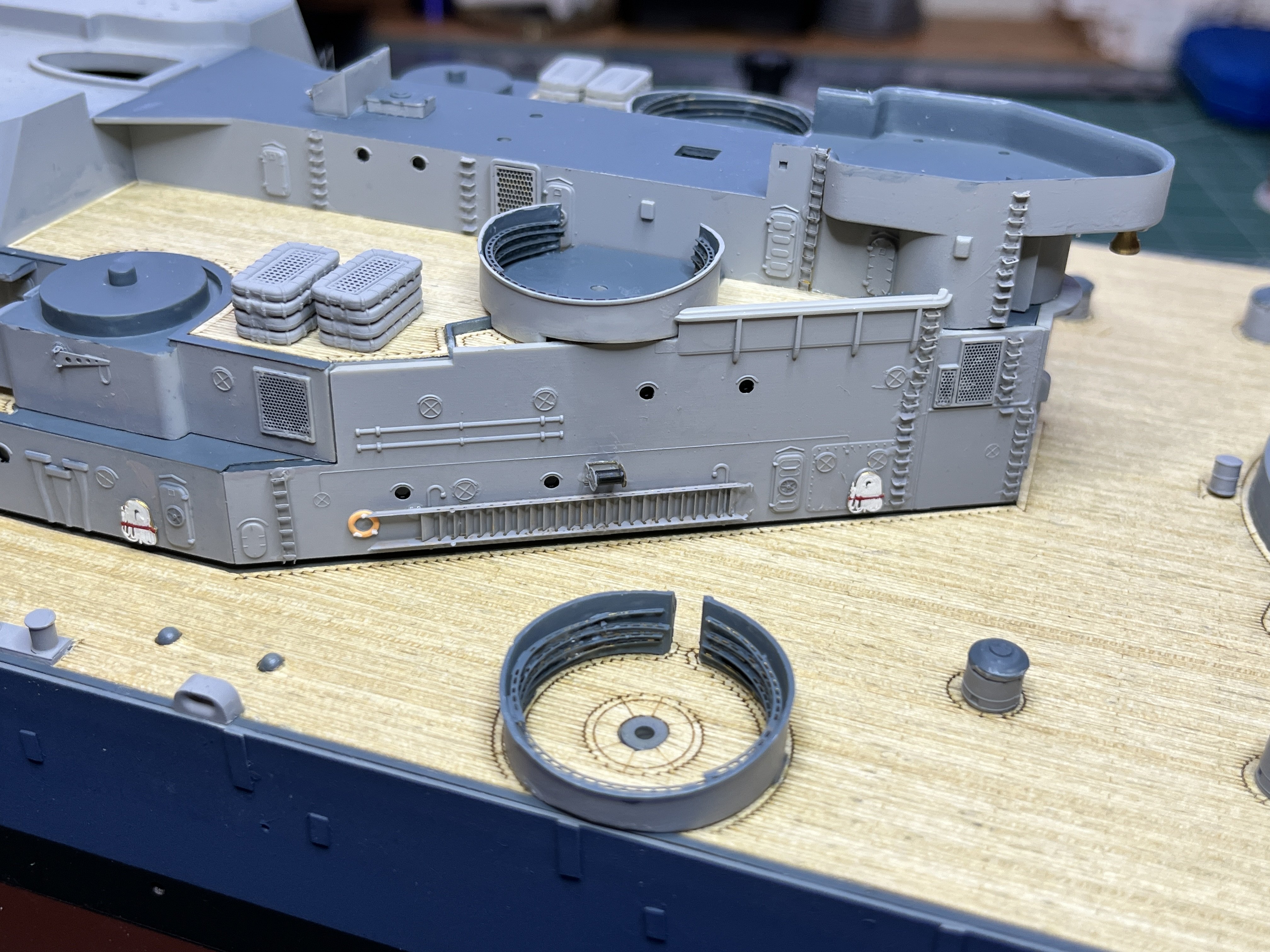
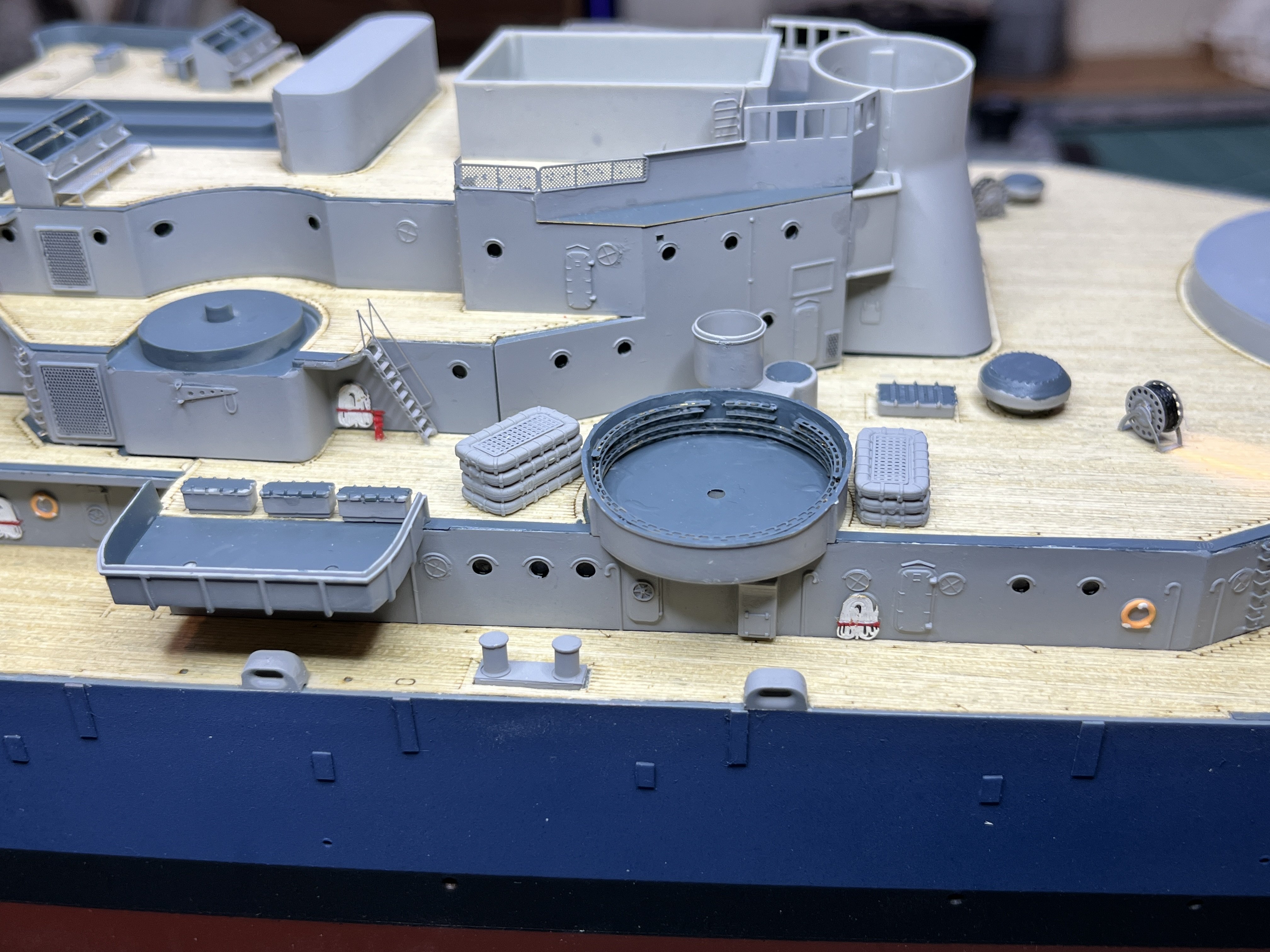
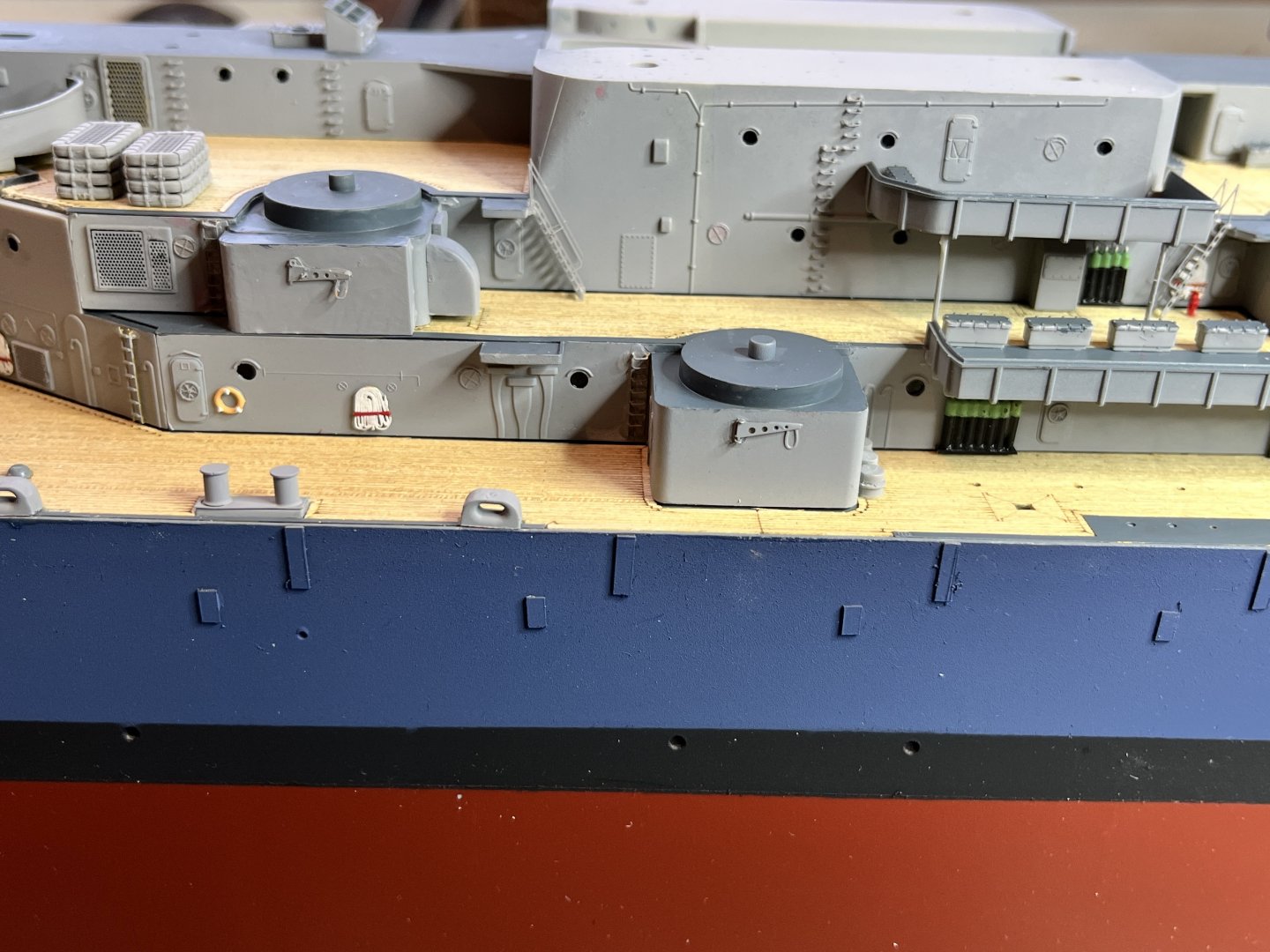
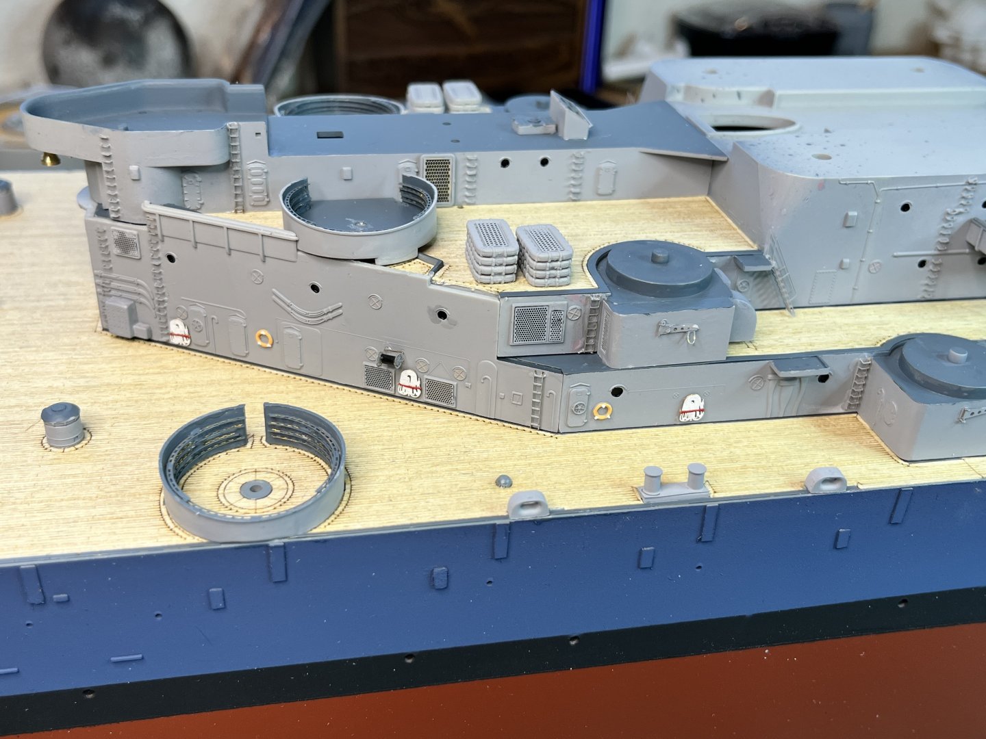
The first three levels above the main deck are mostly complete. All except the guns, railings and everything that attaches the 1st level to the main deck since these first 3 decks are just set in place for now. Here are pictures based on frame number. First up is Port side, frame 68-90. Port side, frame 90-115. Port Side, frame 115-138. I see that the mop rack is conflicting with the three round bits glued to the main deck. Going to have to fix that... Port side, frame 138-151. Starboard side, frame 68-80. Starboard side, frame 80-108. Starboard side, frame 120-138. Starboard side, frame 138-151. Every time I study the plans I discover more things I missed, but these levels are mostly complete. I am reprinting the spare plane float to add supports so it is all one piece. In the mean time I am adding parts to the flag bridge level.


-
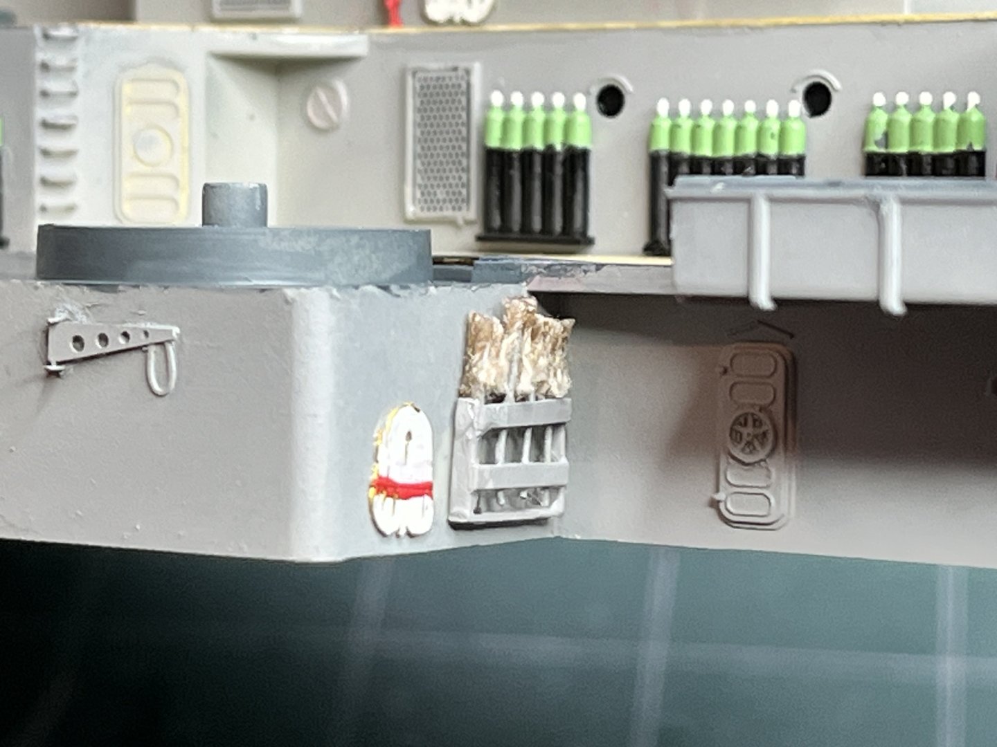
There is a rack of mops shown on the plans at Frame 108, the backside of a 5" gun support. The way I figure it, a mop handle is about 1" or 2.5cm in diameter. At scale that translates to about half the diameter of a 30 gauge wire. 30 gauge is small enough so I attempted to glue bits of thread to the end of the wire. It is tedious and tough to do without the thread absorbing glue all the way along the thread. I used CA glue activator and just a slight bit of glue. Once the threads were added I frayed the ends. The rack is made out of styrene strips. Here is my mop rack.

-
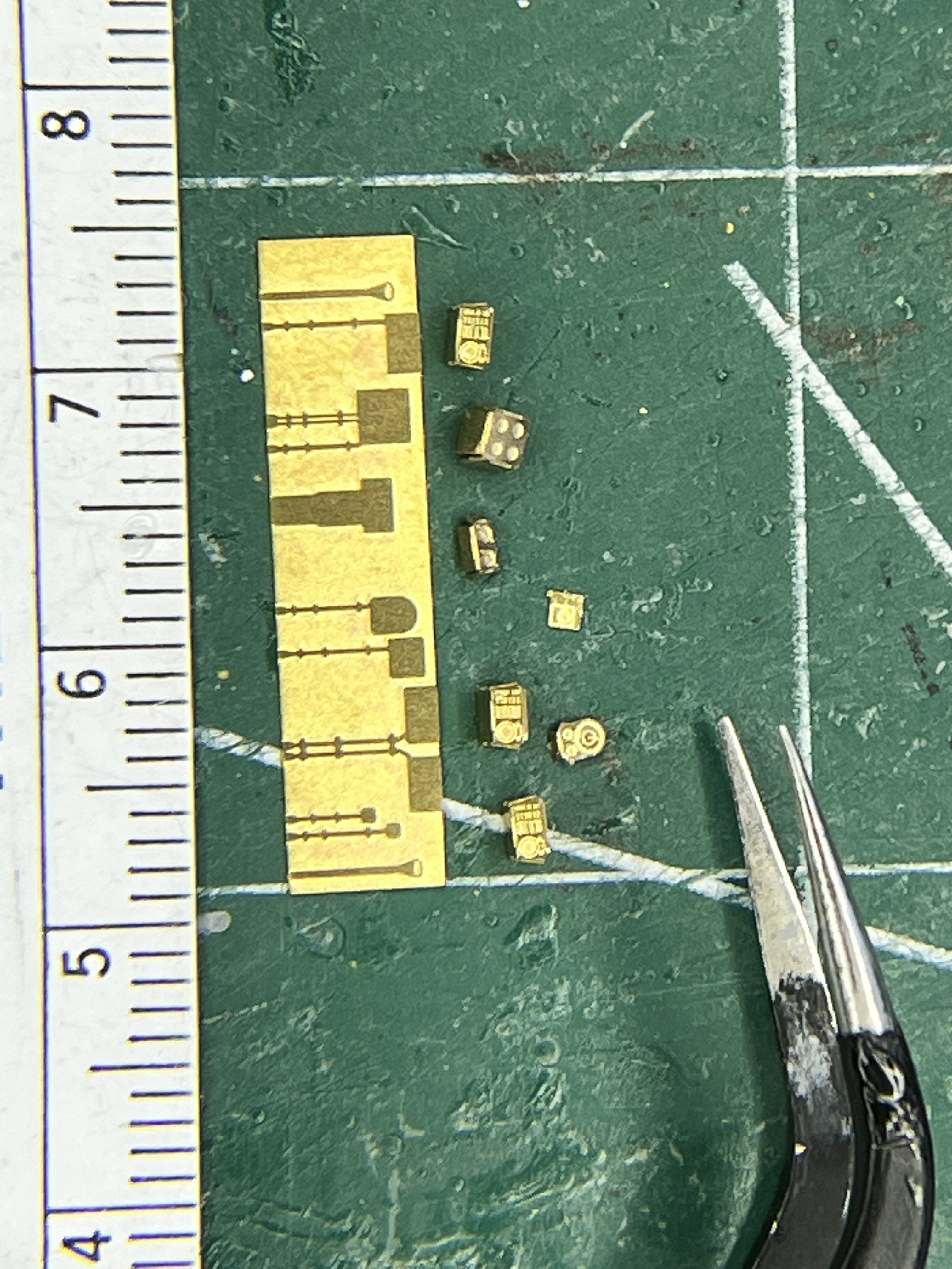
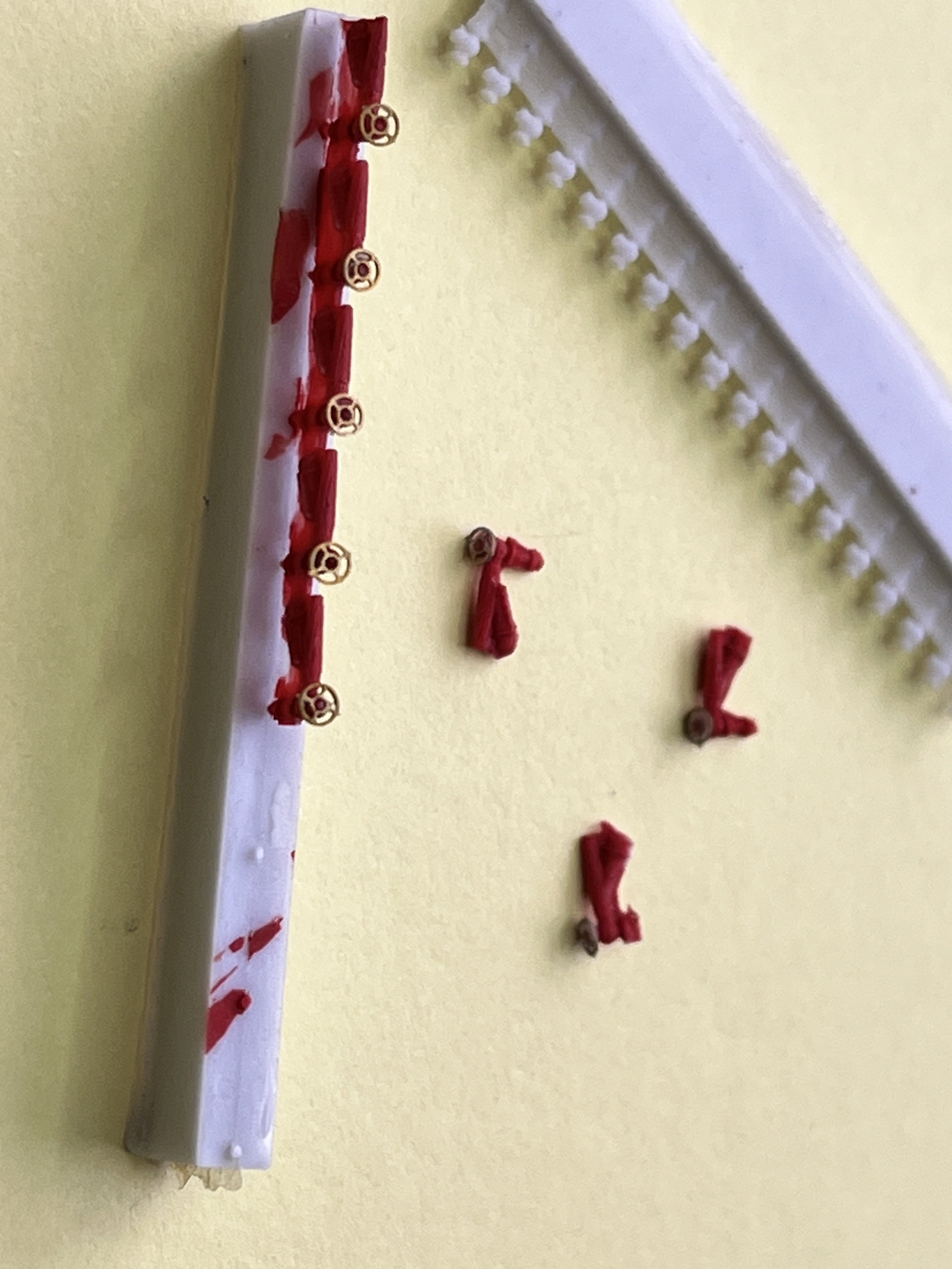
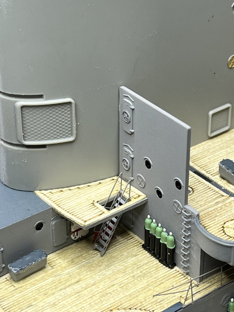
The Pontos 21002F1 kit is definitely taking the concept of crazy small parts to the next level. These fire plugs probably wouldn't even be worth it except they are red and will stand out nicely in a mostly grey model.