


mjcurtis
-
Posts
11 -
Joined
-
Last visited
-
 kuya reacted to a post in a topic:
Boston Whitehall Tender by mjcurtis - FINISHED - Model Shipways - 1:14 (7/8"=1') - first build
kuya reacted to a post in a topic:
Boston Whitehall Tender by mjcurtis - FINISHED - Model Shipways - 1:14 (7/8"=1') - first build
-
yvesvidal reacted to a post in a topic:
Boston Whitehall Tender by mjcurtis - FINISHED - Model Shipways - 1:14 (7/8"=1') - first build
-
yvesvidal reacted to a post in a topic:
Boston Whitehall Tender by mjcurtis - FINISHED - Model Shipways - 1:14 (7/8"=1') - first build
-
yvesvidal reacted to a post in a topic:
Boston Whitehall Tender by mjcurtis - FINISHED - Model Shipways - 1:14 (7/8"=1') - first build
-
yvesvidal reacted to a post in a topic:
Boston Whitehall Tender by mjcurtis - FINISHED - Model Shipways - 1:14 (7/8"=1') - first build
-
yvesvidal reacted to a post in a topic:
Boston Whitehall Tender by mjcurtis - FINISHED - Model Shipways - 1:14 (7/8"=1') - first build
-
yvesvidal reacted to a post in a topic:
Boston Whitehall Tender by mjcurtis - FINISHED - Model Shipways - 1:14 (7/8"=1') - first build
-
yvesvidal reacted to a post in a topic:
Boston Whitehall Tender by mjcurtis - FINISHED - Model Shipways - 1:14 (7/8"=1') - first build
-
Mike Collier reacted to a post in a topic:
Boston Whitehall Tender by mjcurtis - FINISHED - Model Shipways - 1:14 (7/8"=1') - first build
-
ccoyle reacted to a post in a topic:
Boston Whitehall Tender by mjcurtis - FINISHED - Model Shipways - 1:14 (7/8"=1') - first build
-
 Epilogue - With the build completed, it's time to reflect. My primary goal was to get a feel for wooden model ship building and developing skills. I selected this project based more on the skill development potential than the boat itself. Ultimately, with my research and building, I developed a fondness for this little boat. Overall I am happy with my final product. It far exceeded my expectations. It was also nice that there were some opportunities to scratch enhancements based on what I saw in my research. The project is far from perfect, and there are many flaws. The shaping of the bow planking, especially near the keel, is a bit "wonky." There are challenges with twisting planks to meet the keel and even perhaps beveling planks to meet the adjacent plank. There are tricks to learn on better glue management and cleanup. My one knot in this project was a great insight into working with rigging and the delicacy and patience that it will take. Overall this project was a resounding success despite the imperfections. I achieved all my goals and have a finished product that I am proud of. This forum is excellent and supportive, and I look forward to starting my next build. Thank you to all who have chimed in with comments on this build. It was all helpful, informative, and supportive.
- 23 replies
-
- 2
-
-
- boston whitehall tender
- rowboat
- (and 3 more)
-
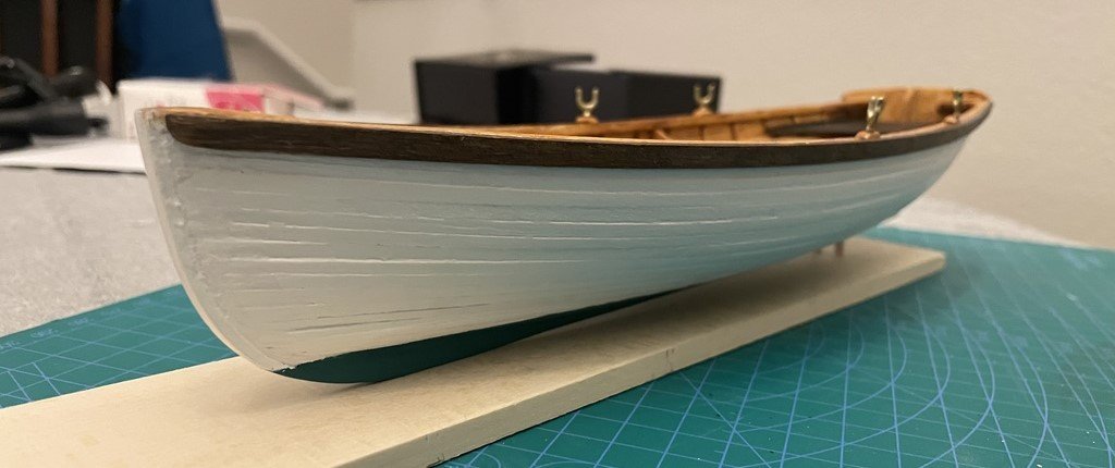
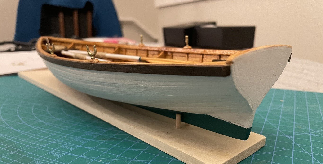
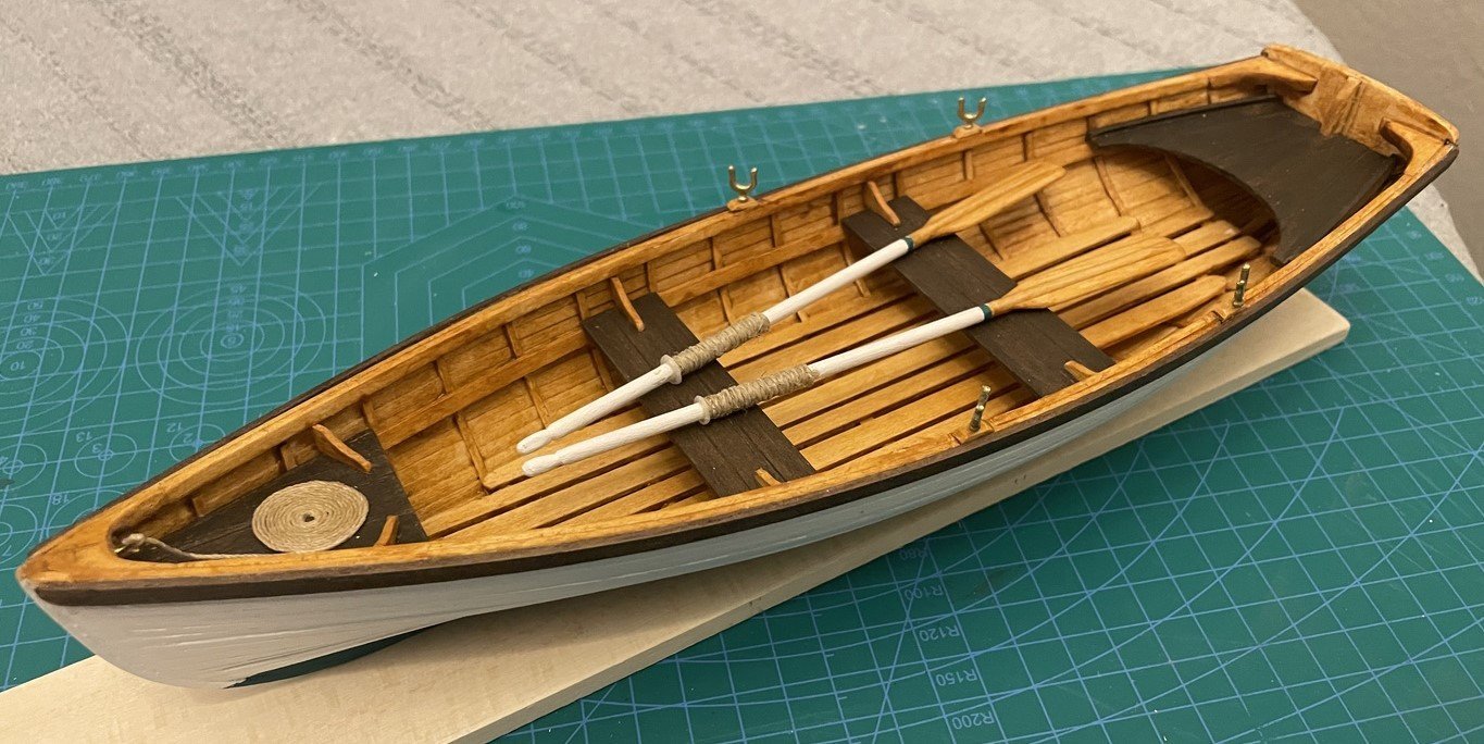
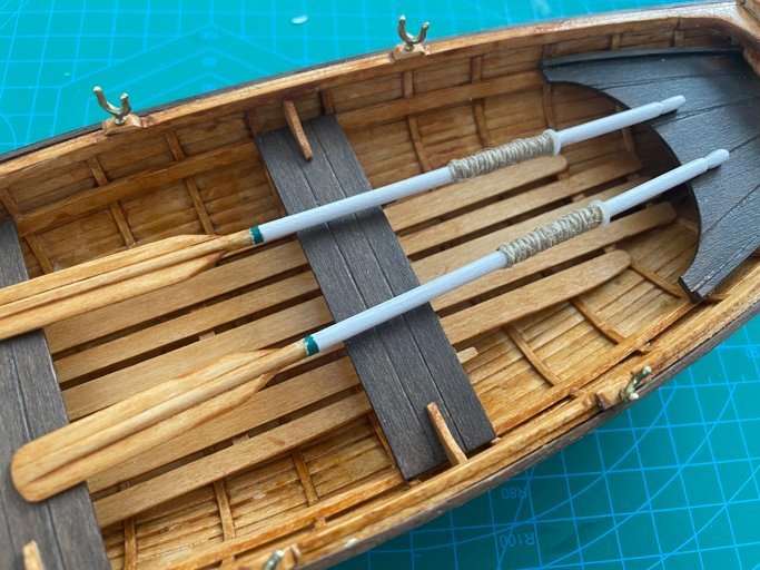
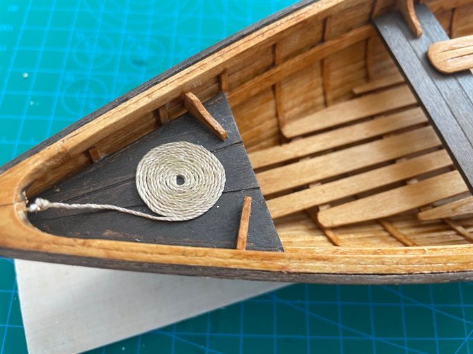
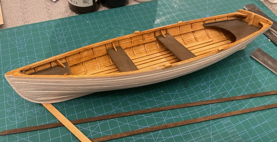
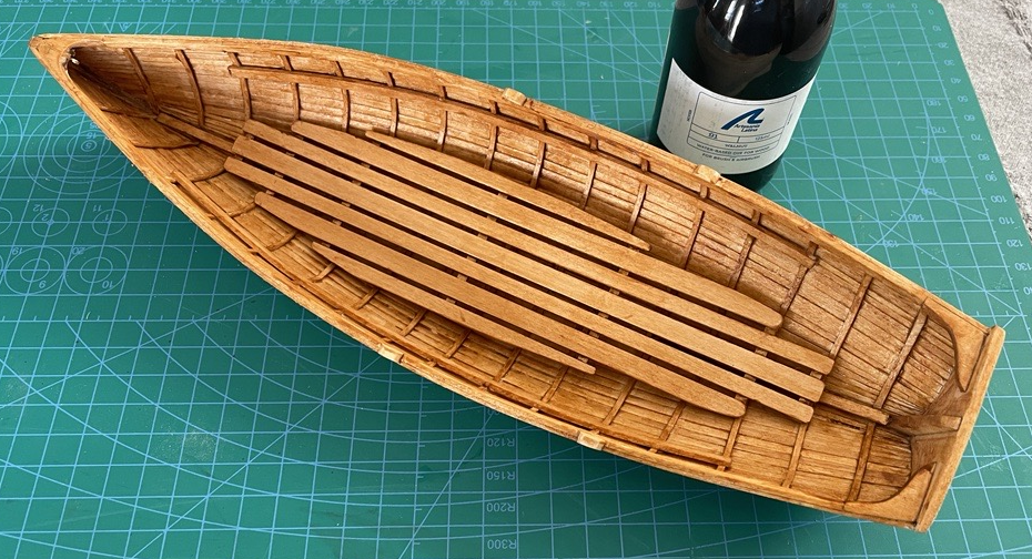
The Seventh Day - [actual build finish date, 10 April 2023] Finishing - With the assembly essentially complete, the final finishing began. The seats and rub rail plank were each given a coat of varnish. The waterline was scribed and masked. The hull below the water line was painted with two coats of Artesania Latina, Hull Green (No. 51). The hull above the water line was painted with two coats of Artesania Latina, Off White (No. 02). The top 1/8" of the hull along the wale was left unfinished to allow for attaching the rub rail. The oar locks were primed and then painted with Artesania Latina, Gold (No. 61), my best simulation of brass. This finishing and previous pre-finishing encompass steps 81 - 82 and the painting instructions. Rub Rails - Steps 62 - 64. The front end of the rub rail planks had been rounded off before finishing. Both rails were clamped together while rounding so that the final shape would be symmetrical on both sides of the boat. In dry fitting, the rails were not fitting well at the bow. The plank seemed too thick to fit correctly at the stem. I sanded each rail to taper the front 1-1/2" of the rail from a thickness of 1/16" to a thickness of 1/32" at the rounded tip. This taper made the rail fit nicely and follow the curve of the bow easily. The rail was glued with PVA and clamped in place. The rail was cut flush at the transom and then beveled 45 degrees. The bevel was touched up with stain and varnish. Towing Eye - Steps 65 - 66. DO NOT drill a 1/16" hole for the towing eye as per the instructions! Measure the actual size of the towing eye provided in the kit. In my case, the eye shaft was .8mm (~1.32"). Because I initially followed the directions, I drilled too large of a hole and had to relocate my towing eye from the stem to the breasthook (Oops). Oars - Steps 71 - 74. The oar handles were cut, and I used a small triangle file to make the initial cut for the handle and then shaped the hand with a sanding board. I wrapped fine-grit sandpaper around the oar handle and then sanded a matching curve on the inside of each oar blade. The oar blade was attached with PVA. Once cured, the oar handle was sanded with a flat taper from the top of the blade until it blended with the blade end, tapered to a thickness of about 1/32". The blade edges were similarly tapered. The blade corners were rounded, and the blade shoulders were rounded and tapered to meet the bladed edges. This was all done with medium and fine sanding boards. The oar blades were stained with the same Oak stain as the interior. A band of Hull Green is at the top of the blade, and the handle is finished in the same Off-White as the hull. Scratch additions: The oars were wrapped with #10 Hemp cord for about 18" at scale. Oar stops were crafted from #6 white nylon washers. The washers had a with of about 1/16", which was trimmed and sanded to 1/32" and then glued to the oar at the top of the wrapping. Completing the Model - Steps 70, 83 - 85. DO NOT drill a 1/16" hole for the oar locks as per the instructions (I learned my lesson with the towing eye and measured first)! The oar lock shaft measured 1mm x 3mm. I drilled a 3mm hole with a 1mm bit, and they fit perfectly. They were secured with a drop of CA on the shaft. The towing eye was also secured into its alternate location with a drop of CA. Coiling the painter was the most aggravating aspect of this build! It looked simple, coil, glue, done. Not even close. After endless attempts, I decided it was time for "professional help" and consulted the Model Ship World forums (yes, that is where I should have started). I quickly found this thread, Making rope coils - Masting, rigging and sails, with ALL the answers. I could now get a good coil and move on to the challenge of a tiny anchor bend knot to secure it to the towing eye. The still sticky PVA-soaked coil was placed on the seat with no worries that it would stay put. Display Stand - Initially, I didn't plan on making the display stand as included in the kit, but after completing the boat, it looked too forlorn resting on its side like so many similar boats I had seen resting on the shore of beaches around the world. I decided to build the basic stand, included in the kit to serve until I could determine what I really wanted to do (remember wood working is another hobby). Steps 75 -80. I had already removed the forms from the base, so I just sanded away the residue glue and flipped to the "good" side. Since I intend that this is a temporary stand, I dispensed with adding a bevel. I measured and drilled the holes for the dowels, cut and sanded the dowels, and voila, a stand. However, this only supported the stern; if you moved the stand, the bow would come off the base. I decided on a good location for two more dowels at the bow. For the bow dowels, I placed them 1/4" apart, drilled, cut, and sanded two more dowels, and again, voila, a more stable and serviceable stand. With the boat finished, thus ended the seventh day ...
- 23 replies
-
- 6
-
-
- boston whitehall tender
- rowboat
- (and 3 more)
-
The Sixth Day - Front and Rear Seats - Steps 51 - 55. Great care was needed in removing the front and rear seats from the die-cut 1/16" basswood. They seemed very fragile and like they could be broken or split easily. The instructions called for marking the faux planks with a pencil following the lines shown on the plan. For a realistic planking effect, I used the back of my Xacto knife blade and a straight edge to emboss the lines into the seats per the plan. The notch in the rear seat had to be enlarged slightly to fit the stern beam. When fitting the stern seat, it was quite a bit narrow for my hull. I decided to glue a 1/16" thick strip of scrap on both the port and starboard edges of the rear seat to make it wide enough to sit on the riser and meet the ribs. This also created a nice edge detail on the stern seat. There was a similar issue with the bow seat. I glued a scrap 1/32" strip to each side, which achieved the needed fit and added an interesting detail like the stern seat. The seats were set aside for finishing before installation. Seats and Knees - Steps 57a - 58. The seats were carefully measured and cut long to allow for fitting. After fitting, I used the same technique as the front and rear seats to emboss two lines on each seat to give them a planked appearance. The seats were set aside for finishing before installation. Again, I deviated from the instructions for the knees and used the scrap material from the seats. It seemed far easier and more precise to rip the 3/4" to about 5/8" and then cut 1/2" high triangles than attempting to cut them from the die-cut scrap. After the six triangles were cut, I wrapped sandpaper around a 1/2" diameter tube to sand the curve in the middle of each knee. Then I shaped the ends with a sanding strip. They were test fit and then set aside for finishing before installation. Finishing Seats, Knees, and Hull Exterior - The front, rear, and bench seats were all finished with two applications of Artesania Latina Walnut dye (No. 91). The walnut rub rail strips were also finished with one application of this same dye. The knees were all finished with the same Artesania Latina Semi-gloss Oak Varnish-dye (No. 06) used for the hull interior. The hull exterior was primed with Artesania Latina White Primer Filler (No. 01). After drying, it was sanded with 400 grit, and a second coat was applied. Seat and Knee Installation - Steps 55, 57b, 59 - 61. Once the finished parts were dry, any glue points were sanded. The stern seat was installed and glued with PVA along the transom, each rib, and at the end of the riser rail. The bow seat was then installed and glued with PVA at the stem, ribs, and forward end of the riser rails. Each of the knees was fit, and each needed additional sanding and shaping to conform to the hull and the seat. They were glued in place with PVA. With the seats installed and finished, thus ended the sixth day...
- 23 replies
-
- 4
-
-
- boston whitehall tender
- rowboat
- (and 3 more)
-
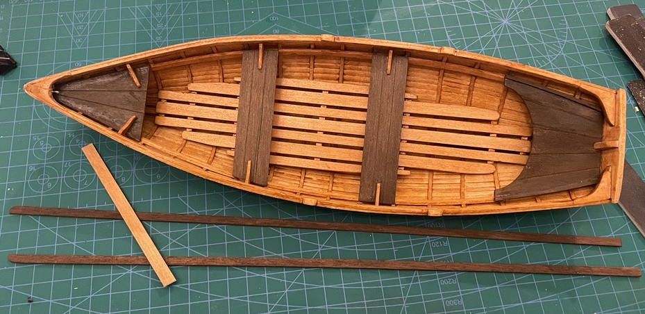
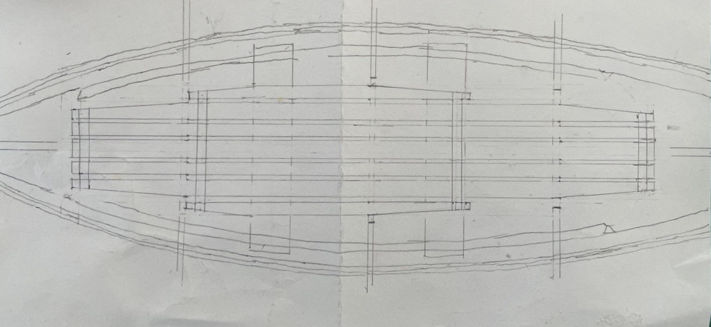
The Fifth Day - Ribs - Steps 43 - 48. Using a taylor's tape, I made an approximate measurement for the eight stern ribs. These are ribs 1-4 on each side that abut the stern keel. I cut them long to allow for trimming to fit. The ribs were soaked in water until very flexible. Each of these eight ribs was surface dried with a paper towel and then fitted, trimmed, and secured using CA. (Regrettably, with the damp wood, CA seemed to be the best option). To ensure consistent spacing, I cut two scaps to the separation length between ribs and used these as spacers at the keel and inwale. Beginning with the 5th rib, the ribs end at the keel with beveled ends (bevels aft for ribs 5-9 and forward for ribs 10-13, ribs 14-16 abut the stem). There are floor strips at ribs 5-13. After installing rib 5, I determined that positioning the keel end of the ribs would be much easier if I first installed the floor strips (steps 47-48). I cut, soaked, dried, and installed the floor strips. I used my spacers to keep these correctly spaced, noting that the floor strips between ribs 9 and 10 change sides relative to the ribs so that the spacer couldn't be used there. With the floor strips installed, I returned to step 45 and proceeded with the remaining ribs. It was now much easier to position the keel end of the ribs using the floor strip as a stop, and I continued to use my spacer at the inwale. The last 11 ribs went quickly and smoothly. Risers - Steps 49 - 50. The instructions for cutting the risers are vague, referencing the 3rd and 14th ribs. I consulted the drawing and determined they should extend about 1/8" beyond each reference rib to support the bow and stern seats. Each rib was marked with the position of the top of the raiser, and then it was attached using PVA and clamped. Floorboards (scratch build) - In my research and the photos posted in the comments here, there are floorboards to support the rower's feet as well as make the boar more comfortable for sitting and entry and exit. This kit did not include any floorboards. I set about drafting a design for the floorboard based on what I had seen in the various photos (my sketch is below). Some were very narrow others were wider and filled most of the boat. I determined that the narrower version was in boats primarily used for rowing and towing. The wider versions were more practical and recreational. I went with a wider design. It was time for a trip to the local Hobby Towne for a couple of strips of 1/4 and 3/16 wide basswood. The plan was to use alternating 1/4" and 3/16" planks for visual interest and 1/8" cross members to support and connect the plank. The floorboards were constructed outside the boat as a flat panel. The cross members were beveled at the end, and the planks were tapered to fit the shape of the hull and with rounded ends. At this point, I am thinking about finishing and when to start before parts of the boat become inaccessible. Taking another look ahead at the instructions and reviewing the final assembly steps, I am at a good point to finish the inside of the hull. This will be easiest if done before installing any of the seats. But the rowlock blocks should be installed now before I do any finishing. So, I will jump ahead and install the rowlock blocks now. Rowlock Blocks - Steps 67 - 69. The rowlock blocks are simply 1/4" pieces of 1/8" stock that is then beveled on each end. A good pair of locking tweezers saved my life when sanding the bevel. The blocks were placed according to the drawing and glued in place. I did not drill the holes for the actual oar locks at this point (step 70). Interior Hull Finishing - The hull interior had been finish sanded with 600 grit sandpaper and tacked before the ribs were installed. The rib surfaces were also lightly sanded, and the hull interior was ready for stain. The floorboard assembly was also finish sanded, and ready for stain. A coat of Artesania Latina Semi-gloss Oak Varnish-dye (No. 06) was applied to the interior, wale tops, rowlock blocks, and breathook. The same was used on the floorboard assembly top and bottom. With the stain dry, the floorboard assembly was installed. With ribs, risers, rowlock blocks, floorboards, and an interior coated of stain, thus ended the fifth day...
- 23 replies
-
- 4
-
-
- boston whitehall tender
- rowboat
- (and 3 more)
-
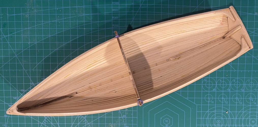
The Fourth Day - More Fairing - Taking the feedback here, I have added a bit more filler in a few spots and done some additional fairing to smooth further and shape the hull. Per the instructions, I did keep put Form 2 back in place to keep the hull from tightening, but there are two problems. First, Form 2 doesn't want to "stay put" and keep pressure on the hull. Second, it appears that just keeping From 2 isn't sufficient to maintain the hull's shape. I determined I could address these issues, but I took all three forms and filed a small notch about 2 cm from each edge in the top. Then I could place each form in the hull and use an elastic anchored in the notch on one side, wrapped over the bottom of the hull, and secured in the notch on the opposite side. This kept the form securely seated and provided the needed pressure to shape the hull. Because my hull had tightened, the forms were not fitting correctly. I resolved this by lightly spraying the entire boat with water and letting it soak in for a few minutes. This allowed the forms to be replaced snugly and the hull to reshape around the forms. At this point, I let it rest and dry for about 24 hours. This didn't address the angle of the bow ( @bricklayer, thank you for your helpful comments on this issue), but it allowed the rest of the hull to reshape around the forms. Quarter knees and Breasthook - Steps 32 - 35. The quarter knees were straightforward. They fit in nicely with a bit of shaping to match the angle of the wales and the transom. I used a piece of scrap placed across the wales and clamped it to the transom as a form to ensure that the quarter knees were straight and level at the transom. Steps 36 - 37. The breasthook was a much different story. With the shape of my bow, the stem wasn't sufficiently proud to fit in the precut notch in the breasthook. Using scrap, I filled the precut notch, then sanded it smooth. The breasthook also had to be reshaped to a much shallower angle by cutting material from each side. I also had to shorter the breast hook side so that it ended with a 1/16" thickness to match the inwale thickness. With all of this rework, the breasthook was complete. Inwales - Steps 38 - 42. The forms were removed, and a notch was added to allow them to fit in place after the inwale was installed. The inside of the hull was sanded to a finished surface before proceeding with the inwales. The inwales were straightforward and installed without issue or complication. With the inwales in place and set, everything was sanded smooth and flush. The reshaping of the breasthook worked and met sharply with the inwales. With a reshaped hull, quarter knees, breasthook, and inwales complete, thus ended the fourth day...
- 23 replies
-
- 3
-
-
- boston whitehall tender
- rowboat
- (and 3 more)
-
@bricklayer I will definitely look for Building Classic Small Craft by John Gardner @iMustBeCrazy and @Bob Cleek, thank you for your comments and suggestions. I am revising my thinking and will do more fairing to remove my poorly referenced "clinker effect." My finishing plan is a painted hull and stained interior.
- 23 replies
-
- 1
-
-
- boston whitehall tender
- rowboat
- (and 3 more)
-
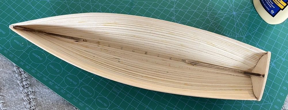
The Third Day - Removing the Strongback - Steps 24 - 25. Removing the planked hull from the strongback proved more challenging than expected. I had expected the brittle nature of CA would allow me to "pop" it free with minimal effort. This was not the case. The taper of the solid transom allowed me to get some leverage on the sides and break it free from the base. It took slivers of the base stuck to the center where it had been attached. I was much more concerned about pressure on the bow. The solution was to use a coping saw to cut between the stem and the base. I was pleased that none of the planks had PCA ooze that adhered them to the forms (I failed to mention on Day One that I used Chapstick on the form edges). With the hull free from the strong back, I could closely inspect inside and out. Overall I am happy with my work to this point, given this is a first build. There are some flaws, but none are serious, and flaws are part of the learning and perfecting process. Fairing the Planks - A close inspection of the completed planking reveals several areas with slivers of daylight visible between the planks (thank goodness this will never see water). Overall the hull seems to be solid. When compared with the plan, the shape is good, but my bow is a bit more pointed. There isn't movement between the planking, even where there are small visible gaps. Using an artist's palette knife, I worked stainable wood filler (Minwax 42851000) into the cracks between planks. Steps 26-28. Most of the fairing effort was in shaping and smoothing the transom and the bow stem. At the transom, I had left the planks slightly long throughout the planking process to allow using an elastic to hold them snug while the CA set on the transom and the PVA set between planks. It also seemed like this extension and the elastic beyond the transom helped keep the rounded shape of the hull. The planking was cut nearly flush with the transom using a coping saw. It was then sanded smooth. A few gaps between planks and transom were filled and sanded smooth. Planks at the bow had been cut at an angle to allow the site to flush with the stem, but the ends were uneven. These were sanded until they were roughly symmetrical while trying to maintain the definition of each individual plank. Overall, the hull was good, and my fairing work focused on the area that needed filler and shaping those to match the plank and minimize the filler to the cracks. Again I wanted to maintain the definition of the planks, so I used a sanding board that looks like an oversized nail filed work along each plank and its neighbor. Steps 29-31. For the false stem, I used a tailor's tape to measure the approximate length of the false stem and cut a 10mm strip which I soaked in plain water for about 10 minutes (instructions suggested window cleaner, which I assume is for the ammonia content). The strip was plenty flexible, and I positioned it holding it in place with elastics, and let it dry thoroughly. Using PVA, the false stem was attached and left to cure. Finally, the false bottom end of the false stem was filed and then sanded flush with the keel. So with the strongback removed and the hull fairing complete, thus ended the third day...

- 23 replies
-
- 4
-
-
- boston whitehall tender
- rowboat
- (and 3 more)
-
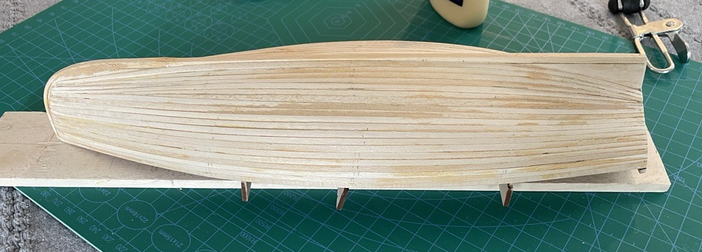
The Second Day - Planking - Nothing like jumping in with both feet. Planking is the most exciting and, as my first build, the most intimidating. With this type of construction, everything relies on the quality of my planking efforts. Based on my reading and limited research into Whitehall Tenders, it seems that all of the planks run the full length of the boat from the bow to the transom. I noticed that the kit instructions have you using full-width planks working from wale toward the keel, and as you near the keel, they do not run the full length of the boat. This seems problematic on two fronts. First, it doesn't appear accurate from what I can find on this type of craft. Second, several planks will only be anchored to their adjacent planks, which seems a bit tenuous, especially since I prefer using PVA in this application. I decided to ignore the instructions and proceed by tapering the planks as needed to ensure that all planks extended the full length of the boat. Steps 21 - 23 (my version). This is based on a combination of techniques I had seen in my reading. Since the wale plank was already in place, I next proceeded to install the garboard strake along the keel. This was a challenge since it had to contend with both the boat's bow and a twist to align with the transom. The forward part of the plank was tapered substantially to fit along the forward keel. The aft portion of the plank had to be beveled so that with the twist, it met flush with the aft keel and the transom. Getting everything fit, aligned, glued, and clamped on both sides of the boat took a while, but I was very pleased with the results. With the garboard strake in place, I measured the distance between the wale plank and the garboard at the bow, form 1, form 2, form 3, and the transom. The distance on form 2 was 54mm, exactly 18 times the width of the provided planks. Based on this, I divided the other measurements by 18 to determine the plank width at each form. I created a table similar to the following: | B | 1 | 2 | 3 | T | Form | 44 | 49 | 54 | 49 | 34 | Plank | 2.4 | 2.7 | 3.0 | 2.7 | 1.8 | Based on this table, I sketched out a template that I could use for tapering each of the planks. I trimmed and added each plank one by one using a 70/30 diluted PVA along the edge of each plank with CA on the bow and transom. I used binder clips on the forms to keep each plank snugged up to it adjacent plank and elastics between forms to keel the planks tight against the forms for the right curvature. Planks were added alternating port and starboard. This allowed me to check my accumulated measurement after each plank was added and adjust if needed on the next plank. I repeated this process for nine planks. At that point, I was to where there was a sharp curve in the hull transitioning from side to bottom. At this point, I decided to change and add planks from the garboard downward with the idea that it would work best for the planking to meet this change in curvature. This worked well, and the final plank took some work and measuring with the calipers to get just the right tapper to fit snuggly. Now that all is said and done, I am very pleased with the planking outcome. There is a slight clinker effect which is historically accurate, and I will try to maintain it when fairing and sanding. There are a few places where I see slivers of daylight between planks. So with the hull planked, thus ended the second day...
- 23 replies
-
- 6
-
-
- boston whitehall tender
- rowboat
- (and 3 more)
-
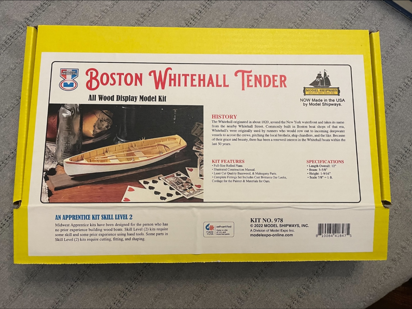
The First Day - [actual build start date, 9 Mar 2023] The Adhesive debate - As a long-time woodworker, my initial assumption regarding adhesive for model shipbuilding was PVA. While doing my preliminary research, I was surprised that some, maybe many, use cyanoacrylate adhesives. I didn't think cyanoacrylates worked on wood, so I would have never tried them on a wooden ship. I did make limited use of them in plastic models because of their quick setting properties, but in general, I found them to be messier and more brittle than the purpose-made liquid adhesives for plastic models. This experience leads me to expect that, in general, PVA adhesives will be the best option for wooden ships and what I plan to use. However, I am not throwing out the idea of cyanoacrylates. Along with my old woodworking favorite, Tightbond II, I have Tightbond Instant Bond Wood Adhesive, thick and medium. I expect I will find some situations where these will have a purpose (I bought a can of accelerant too). The Model Kit - Upon inspecting the kit contents, I initially thought, "there isn't much here." Only three small sheets of laser-cut parts, a solid block of basswood, a couple of dowels, and a large bundle of assorted wood strips. There was also a pouch with some "rope" and four cast oarlocks. The first step was to inventory the kit contents, all present and accounted for. The instructions we neatly laid out with convenient checkboxes for everything to track progress. I will say that I was disappointed with the resolution and clarity of the illustrations and the printing. Overall they are a bit "fuzzy" and lack detail. I perused the getting started section, and there it was, the first two items, thick and thin cyanoacrylate adhesive! Not a mention of PVA adhesive; accelerant was on there, too, further down the list. I checked off the suggested items and was pleased I had everything due to my research. I read the entire instruction booklet to ensure a good overview of what was coming. Building the Strongback - Steps 1 - 8 were all about building the strongback. I was unfamiliar with a strongback and had to stop and do some quick research. This building approach felt daunting for a first build since I wouldn't attach the spanking to the supports. Planks would just be attached at the bow and the transom along with their neighboring plank. This could be tricky, especially with my commitment to PVA. Based on this, I modified the adhesive plan to be PVA between planks and CA at the bow and transom. I felt that the PVA would provide a stronger bond between the planks in the long run, but it was unrealistic to expect it to set quickly enough to hold at the bow and transom without severely limiting progress. The PVA between planks would have time to cure between "days." The strongback parts were cut, sanded square, and assembled. I elected to use CA for attaching these to the base. It seemed like the brittle nature of CA would be an advantage here since they would need to be broken free later. I used a handy tick I had read about to endure things that were square by clamping the form to a Lego and the lego to the base. This worked very well, and the CA doesn't like Legos. Keel Assembly - Steps 9 - 14 were the assembly of the keel, the bow, and the transom. The parts were laid out, marked, assembled, and trimmed per the instructions. Steps 15 -16 attach the bow/keel/transom assembly to the strong back. Again I elected to use CA since I expected it would be easier to break free from the strongback when the time came. Steps 17 - 20 were installing the gunwale planks, starboard, and port. This required beveling the bow end of the plank to meet with the side of the bow plate. A small drop of CA was used to secure the plank. I used a small clip to hold this in place while the CA set and I positioned the transom end of the plank. I had put elastic bands around the strongback and keel assembly at each form to help hold the plank against the form. The plank was left slightly longer to be trimmed flush later at the transom. Leaving it long made it easier to avoid gluing my fingers to the transom and allowed me to use an elastic band just past the transom to hold the plank(s) in place while the CA set. So with the strong back complete, the keel assembly in place, and both gunwale planks attached, thus ended the first day...

- 23 replies
-
- 7
-
-
- boston whitehall tender
- rowboat
- (and 3 more)
-
Prologue - Since I am new to this hobby, I began with some general research on the topic of model shipbuilding before selecting my first kit/project. This research proved very eye-opening and provided valuable perspectives on what I should consider and expect from my first project. I consulted the following resources in my research: Ship Modeling Simplified by Fran Mastini Planking Techniques for Model Ship Builders by Donald Dressel Historic Ship Models by Wolfran zu Mondfeld The first two titles provide detailed insight into the process of model shipbuilding. They made it clear that there are many skills and techniques that I will need to learn and master as part of this journey. They also made clear the importance of selecting an appropriate starting project. A project that is driven more by the skill and technique-building opportunities than by the ship itself. My research also revealed much more craftsmanship in wooden model shipbuilding than I expected. Coming from plastic models, the kits are mainly about assembling the parts in the correct sequence with added finishing details along the way. Most of the effort is in the overall finishing to add the desired level of detail and realism. My research showed that much of the actual assembly of the ship requires remarkable attention to detail and fine craftsmanship to get the proper lines, fit and final appearance. This craftsmanship involves an assortment of tools that I hadn't previously considered. The suggestion on tools and their uses and application was invaluable and gave me a good idea of what would be essential before I started my first project. I quickly realized that rigging is a project in and of itself. While rigging is one of the great appeals of model shipbuilding, it became clear that a ship sans rigging was the best starting point (I am looking to see if there is a book specifically on this topic similar to the book on planking). The third title was exciting because it appealed to my fascination with realism in any model building. It provided a multitude of details on ship construction, rigging, equipment, and mechanicals. This will undoubtedly be a valuable resource as I progress to more complicated projects. For the Whitehall, there are limited opportunities to apply much of this information. Armed with my research, I began the process of selecting my first project(s). Planking is a critical element of all model ships, but it appears planking can get quite complex. So I began looking for an option that would allow me to start developing planking skills with a simple hull design. This led me to look at various "rowboats." Ultimately, I decided on the Boston Whitehall because it had a simple bow and transom stern. This would be a good starting point for working out the detail of a pointed bow while keeping the stern simple. It was an attractive boat with some historical reference. There are still makers of Whitehall Tenders today over 200 years on. While selecting my first kit and tools, I came across several other interesting kits and, in a couple of cases, "deals," so I already have a backlog on the shelf to flow the Boston Whitehall. This backlog consists of the following: Maine Peapod by Model Shipway (the pointed bow and stern seemed like a good additional skill-building second build, and the lobster trap is a fun bonus) H.M.S. Bounty Jolly Boat by Artesania Latina (similar to the first two rowboats, a more significant launch that also provides an introduction to basic rigging) So before I get started, I have three builds planned... as I said, I tend to be an overachiever. Notes: This post is a prologue with reference background on my initial thoughts and processes. I plan to proceed with log posts for each build day, using days in the biblical creation sense where each is a period or phase, not necessarily a chronological day.
- 23 replies
-
- 4
-
-
- boston whitehall tender
- rowboat
- (and 3 more)
-
mjcurtis changed their profile photo
-
This will be my first attempt at a wooden model ship. I have been fascinated by intricate wooden model ships for most of my life but never dared attempt one. The Boston Whitehall Tender was chosen not because it's an exciting ship but because it was rated as an entry-level kit, and the price was right. I am a perfectionist and know that the best way to fail miserably with extreme aggravation is to take on too tough of a build. With that said, the Whitehall Tender does have an historical legacy. It looked like a good option for my first build. In my youth, I built a vast collection of plastic model aircraft. All were 1:72 scale and covered various types, from WW I biplanes to modern-day jets. I attempted one plastic ship model of the USS Constitution but was disappointed. The final product lacked the realism I desired. I was incredibly disappointed in the plastic rigging and molded sails. It just did have the realism that I expected and was able to impart to my aircraft models. So began and ended my only other foray into model ship building. Now 4-1/2 decades on, I will give wooden shipbuilding a try... stay tuned to see how this unfolds.
- 23 replies
-
- 8
-
-
- boston whitehall tender
- rowboat
- (and 3 more)
