mysticlee
-
Posts
37 -
Joined
-
Last visited
-
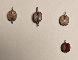
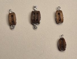
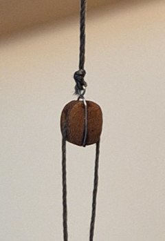
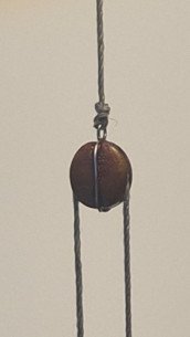
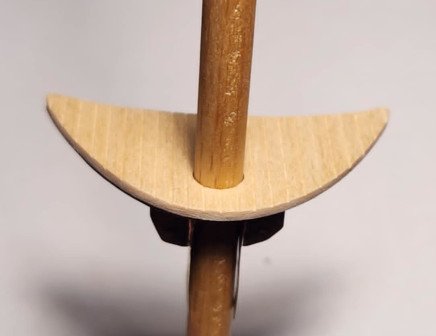
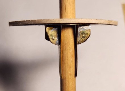
Since the Eagle uses internally stropped blocks, I wanted to replicate that to the extent possible. I looked at the iron stropped blocks from Bluejacket Ship Crafters, but they don't have the wood look that I want. And I didn't find any other sources for stropped blocks in the sizes I need (3mm, 4mm, 5mm) So recently I purchased several sizes of Syren blocks, and quite a long time ago I purchased one size of MS Beautiful Blocks, with the intent of using wire instead of thread/rope to strop the blocks. Below are photos of several 4mm blocks stropped with 32 gauge stainless steel wire. The top row is MS BB blocks, and the bottom row is a Syren block. The two on the top left are an attempt to make both a top eye and a bottom becket (I used the wrong size wire, 28 gauge, for the becket on the left block, and all wire on the second block). Below are two 4mm blocks, MS BB on the left, Syren on the right, temporarily rigged with thread (not made into rope, so forgive the frayed ends). In general, I found it easier to strop the MS BB blocks because the block face is flatter, and the groove is deeper, than the Syren blocks. I also did some tests with Syren 3mm blocks, and stropping them was quite a bit more difficult than the 4mm blocks. In all cases, I used some CA on the sides and bottom to hold the wire in place. I found that the color on the Syren blocks bled a bit into the CA, and turned it red. I probably used too much CA. I'm leaning toward the MS BB blocks for several reasons. I think the look of the real wood and flatter face matches better to the Eagle's blocks. Second, the best way I found to make the beckets is to drill into the bottom of the block and insert and CA an eye with a twisted stem, which was more difficult with the Syren blocks. Finally, it was easier overall to strop the MS BB blocks than the Syren blocks. That's all for now, Lee
-
 CiscoH reacted to a post in a topic:
Syren Ship Model Company News, Updates and Info.....(part 2)
CiscoH reacted to a post in a topic:
Syren Ship Model Company News, Updates and Info.....(part 2)
-
Canute reacted to a post in a topic:
Syren Ship Model Company News, Updates and Info.....(part 2)
-
Canute reacted to a post in a topic:
Syren Ship Model Company News, Updates and Info.....(part 2)
-
thibaultron reacted to a post in a topic:
Syren Ship Model Company News, Updates and Info.....(part 2)
-
thibaultron reacted to a post in a topic:
Syren Ship Model Company News, Updates and Info.....(part 2)
-
Thanks for the quick reply...I figured 2mm would be a bridge too far. Are the 1/8 internally stropped blocks in production? Otherwise, I'll probably go for either rope (thread) or wire stropping the Syren 2mm and/or 2.5mm 3D printed blocks. Regards, Lee
-
Chuck, your pics for the 3D printed internally stropped blocks back in October caught my attention. They look great! How small have you been able to make them? Anything approaching 2mm? I'm working on a model of the USCGC Eagle (1:102), and being a relatively modern ship, all of the wooden blocks are internally stopped.
-
vvvjames reacted to a post in a topic:
USCGC Eagle by mysticlee - Constructo - 1:102
-
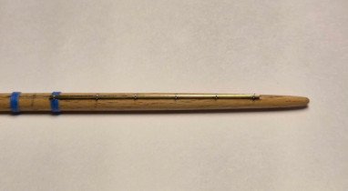
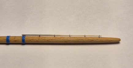
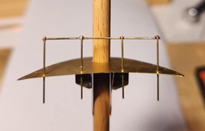
Progress has been slow and sporadic, but here's my latest bit of work. I wasn't sure if I wanted to include jackstays on the yards, or how hard it would be to make them, so I constructed a test yard (the size of the royal) with jackstays. The spacing of the supports is about double what the scale would dictate, but I can live with the variation. The jackstay is made from 0.50 mm (0.020 in) brass rod, and the support eyes are made from 32 gauge stainless steel wire (using the "twist around a post" method). The photos show two views of half of the yard (total length is 4 3/8"). The blue bands are on either side of center, and will also be the position of the eyes for the metal blocks for the clew lines (on the bottom of the yard). Nothing is glued or painted for this test. With the addition of the other attachment points, the entire yard, including the jackstay, will be painted CG spar color, with the yardarm painted white. I'm happy with the results, although the fabrication was tedious, especially making the eyes for the supports, and drilling the holes for the eyes. That's all for now. Lee
-
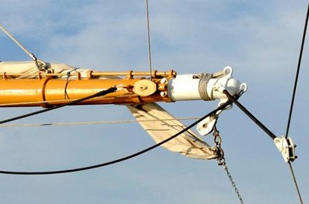
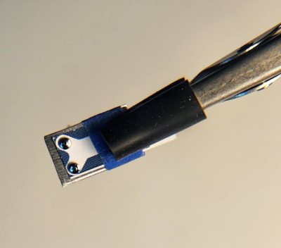
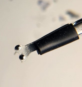
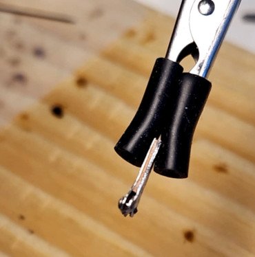
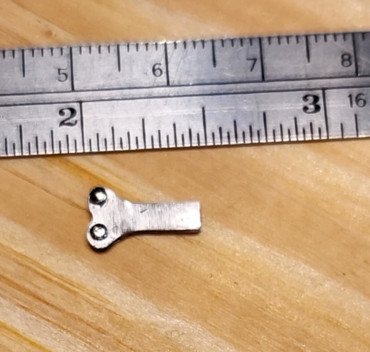
As previously mentioned, the Eagle uses metal blocks for guiding wire ropes for sheets, clews, halyards, and braces. The working ends of the wire ropes eventually connect to wooden blocks that guide fiber ropes down to the deck for the cadets to handle. Below is what the upper topsail yard/yard arm looks like on the Eagle. I experimented with several methods of fabricating metal blocks like the two white ones shown in the photo (one for the clew, and the other for the brace), and settled on using pieces of sheet aluminum for the sides, a piece of a straight pin for the axle, and a loop of wire sandwiched between the sides and around the axle for the sheave. I used CA to glue all the pieces together. It's not intended to be a working block, just to look like one. I drilled a hole at the end for use in connecting the block to either an eye attached to a yard, or to another wire rope (or in the case of some of the braces, a piece of wire simulating a length of metal bar). I'll be using gray thread to replicate the wire rope. I made several sizes of blocks, wanting to keep as close as possible to the scale size of the actual blocks. I estimated the smallest ones (which is the majority of the blocks) are between 6 and 9 inches long, so to scale would be 1/16" to 3/32". I was able to make decent ones at 3/32" but the attempts at 1/16" were unacceptable. The largest ones will be 1/8". I previously developed a method, in post #28, for making the sheet sheeve that is attached directly to each yard, as shown in the photo above. I decided to make a test yard/yard arm with the metal blocks, sheet sheeve, and attachment points (eyes) for the brace, foot rope, and Flemish horse. I omitted the eye on the top end of the yardarm, and haven't decided yet on how to replicate the jackstays on top of the yard. The photos below show my test yard/yard arm (which is suspended by the arms of a Quad Hands, not visible in the photo). The size of this test yard is actually a bit smaller than the size of the royal yard, so I should have no problem constructing all of the yards with the various attachment points. I ended up using thin blue masking tape for the metal bands around the yard at various places. The eyes are formed from 28 gauge wire and fastened using CA in hand-drilled holes. First I painted the yard/yard arm with two coats of shellac, lightly sanded, and then painted the yard arm and metal block white, and a portion of the yard light tan color (two coats of Testors enamel paint for each color; I'll probably go with a third coat for the actual model since the paint is still a little thin as is evident in the photo). For production, I'll use a color for the yard (and many other parts of the model) that is much closer to Coast Guard spar; True North Precision Paints has a color they show as an exact match, and I have some on order...will be testing once the order is received. I ran two threads on the test jig to approximate how the sheet (from the sail above) and the clew (for the sail attached to this yard) will show in the model. The hardest part of putting the parts together was attaching the metal block to the eye, using a small loop of 28 gauge wire. I'm happy with the overall look of the yard/yard arm, and especially of the metal blocks, so I'll continue making the ones I need (8 made so far, 62 to go). That's all for now. Lee
-
Thank you rwnw for the links to the Eagle Plans (and sorry for the delay in responding, I've been distracted by other projects around the house until recently). I already had found the plans (per my post #30) and found the sail plan especially useful. I didn't do anything with the body plan or engineering arrangement since my build is already well along, and I'm not inclined to make changes to the hull at this point. In the past several days I've been completing my tests in constructing metal blocks that are used extensively on the Eagle (since it uses wire ropes for much of the running rigging), and also doing some preliminary paint tests. I'll have more on these efforts soon. That's all for now, Lee
-
SiriusVoyager reacted to a post in a topic:
USCGC Eagle by mysticlee - Constructo - 1:102
-
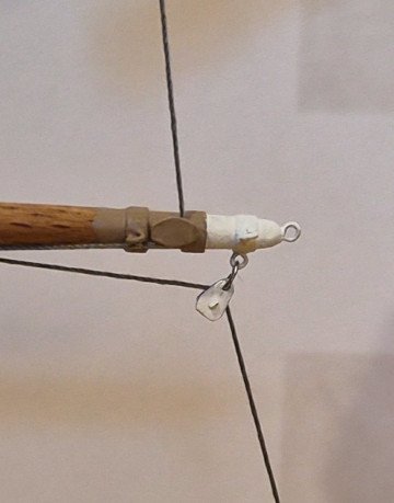
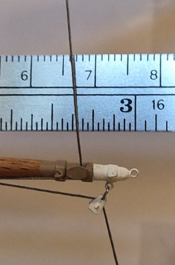
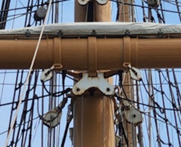
Time to report on my latest work...upper crosstrees. First is a picture of the Eagle's mainmast upper crosstree, viewed from below. The structure is metal beams/bars (painted Spar color), with the area surrounding the main and topgallant masts covered with wood deck planks (hard to see in the picture). Note how the base of the topgallant mast extends below the crosstree structure, which allows for lowering the mast when transiting under bridges, etc. Also note the two futtock shrouds on each side, and the corresponding turnbuckles for the topgallant shrouds that are attached to the futtock shrouds where they pass through the crosstree and decking. Several standing rigging lines (main topmast stay in front; topmast shrouds from below, etc.) pass through openings on either side of the main mast and are secured around the mast (not visible in the pic). My construction plan is shown below, along with pictures of the crosstree after fabrication. The metal frame pieces, shown in blue on the drawing, are made of copper wire, bent to the shape shown (for the outer piece), hammered flat, and filed to smooth the sides and ends. The tan area shown in the drawing is made of thin brass sheet, with holes cut for the two masts and two openings for standing and running rigging. Tiny holes drilled are for the futtock shroud terminating in eyes above the crosstree for attaching the turnbuckles. In order to provide a secure attachment to the main and topgallant masts, I made a pair of mast bands (one below the crosstree, the other at the top of the mainmast above the crosstree) by bending a strip of brass around both masts, pinched in the middle, with a 1/16" space in between to separate the masts. The copper wire pieces and the mast band were then soldered to the bottom of the brass plate. Two side supports were also soldered to the brass plate. The decking was made from basswood, scored to resemble decking, and with holes cut to match the holes in the brass plate. Here's a few pictures of the crosstree test-fit to the masts. Still a bit of clean-up to do (such as removing the solder resin), and eventually, painting. That's all for now. Lee


-
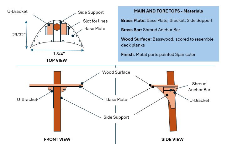
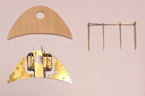
Finally back to work on the Eagle model! As noted previously, the ship's tops are constructed of metal framework with a wood plank surface. After considering several ways to model the tops, I settled on using brass sheet metal for the base plates and side supports, thicker brass metal for the U-bracket, and basswood on top. My plan is shown below: I needed a way to anchor the main and fore shrouds underneath the top surface, and it needed to be strong enough to withstand the pull of the shrouds when they are pulled taught. After forming the U-brackets and filing their profiles as shown in the front view, I soldered the U-brackets to the port and starboard sides of the the base plate bottom, then soldered the side supports to the base plate and U-brackets, followed by soldering the anchor bar through holes in the U-bracket. I drilled a small hole for the mast opening, just enough to use a round metal file to enlarge it to just fit the mast. Same with the wood surface. I also drilled holes in the base plate for the upper ends of the futtock shrouds to pass through the top and as anchor points for the topmast shrouds. Holes along the back edge of the top are for a safety railing, on which is fastened rope netting on the ship. I was originally going to use wood veneer for the wood surface, but I found that it wasn't stiff enough to make a rigid structure (the brass sheet has a lot of flex). So instead, I used 1/16" basswood, and to simulate planks, I scored the top surface using a blunted straight pin along a ruler, following several suggestions and techniques I found online. Below are pics various view of the base plate/bracket assembly, wood surface, and railing, test fitted to the mast. I'll clean up the solder resin before painting the various parts (railing is white, all other metal parts are spar color). I'll also stain the wood surface to resemble the wood on the ship, and paint the edge white (as it was in 1972 on Eagle). I haven't glued the wood surface to the base plate yet. Once that's done, I'll drill through the holes in the baseplate through the wood surface. I'll also drill and file the slots for the running rigging at that time. The railing bottoms will be cut flush with the bottom of the base plate at final assembly. When I (eventually) get to mounting the masts to the ship's deck, I'll tie the shroud threads to the shroud anchor bar and seal with a touch of CA, and leave the ends long until I'm ready to fasten the lower ends to the turnbuckles attached to the deck. Then I'll add the futtock shrouds, since once they're installed, it will be hard to reach the shroud anchor bar. I already fabricated the top for the mizzen, which is more simple and smaller (about 60% the size of the main and fore tops). The mizzen top has no railing, and no slots for running rigging. Next will be the upper tops/cross trees, once I finalize the plan/drawing. That's all for now. Lee
-
ccoyle reacted to a post in a topic:
USCGC Eagle by mysticlee - Constructo - 1:102
-
ccoyle reacted to a post in a topic:
USCGC Eagle by mysticlee - Constructo - 1:102
-
king derelict reacted to a post in a topic:
USCGC Eagle by mysticlee - Constructo - 1:102
-
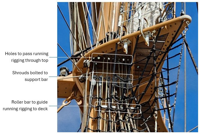
The tops on the Eagle's fore and main masts are made of metal framework with wood planks on the upper surface, as shown in the below picture. Highlighted in the picture are: 1. Holes in the planks to pass the running rigging (both wire and fiber rope) from above (similar to lubbers holes on 19th century and earlier ships) 2. A roller bar (behind the shrouds) to guide the running rigging down to the deck 3. Shrouds bolted to a support bar Other items visible in the picture are the four futtock shrouds, and the turnbuckles for the topmast shrouds that are attached to the tops of the futtock shrouds as they pass through the metal framework and planks. The top on the mizzen mast is similar but smaller. I'm developing a plan for modeling the key features of the Eagle tops using brass sheet metal for the metal pieces, and wood veneer for the planks. More on that in an upcoming post. BTW, the upper tops/crosstrees are also constructed of metal framework and wood planks, but have a different design. I'll discuss the details and modeling plan for those in a separate post. That's all for now, Lee
-
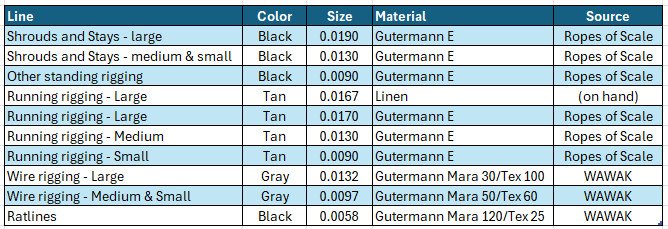
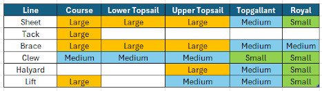
It’s been a month since I posted on my build log…other projects compete with my ship building (yard work, roof repairs, new hardwood on the second floor, maintenance of my family history website, golf, etc.). But I have done some work on the model. I finished my research of the sizes of standing and running rigging lines, using several sources, including: Horst Wessel (now USCGC Eagle) blueprint that I discussed previously; Underhill's Masting and Rigging the Clipper Ship & Ocean Carrier; Rigging spreadsheet at Model Ship World for size of blocks and diameter of ropes; Lloyd’s standard specification for standing and running rigging; and Size of lines used by a few other modelers for model ships of similar scale to mine. After factoring all the data from the various sources, I have selected the following thread sizes and sources for the various standing and running rigging: My selection of the black and tan thread sizes was driven in part by the selection of dark gray thread from WAWAK for the wire running rigging. WAWAK has several sizes of Gutermann Mara threads, but not all of them come in dark gray. Once I found two sizes that were acceptable, I selected sizes for the black and tan threads from Ropes of Scale, keeping in mind that the dark gray threads, representing wire running rigging, should be smaller than their corresponding fiber running rigging. And the black threads for the standing rigging (also wire on the real ship) should be similar or a bit larger than the running rigging. Note the oddball entry in the above table: linen thread. When I first started this ship model in the 1970s, I purchased a 50-yard spool of Ashaway Cuttyhunk linen line, Zane Gray No. 3, Twisted 50’s LEA, as a replacement for the fuzzy thread that came with the model. From what I’ve read, linen was the thread of choice for ship models until polyester (Gutermann, etc.) became widely used, so I wanted to make use of this thread if it would blend with the other threads in both size and color. I couldn’t find any specification that told me the diameter of the linen line, so I counted the 60 turns on the one-inch wide spool, resulting in a diameter of 0.0167 inches, a close match to the large size running rigging. It’s light tan in color, and I’ll find out if it will blend well with the tan thread from Ropes of Scale when I receive that line. I summarized the relative sizes of running rigging lines for the square sails as follows: For simplicity, I have decided not to model buntlines or leach lines, and I’m still on the fence regarding whether to model no sails or furled sails (I’m leaning towards the latter). I’m still working on the threads needed for the stay sails, gaff and spanker, but I’m limiting which lines to represent for these sails, probably to only halyards. Once I determine the total length of thread I need for each size, I’ll place my orders for the thread. I’ll conclude with a note about my overall work plan. You’ll note that I haven’t painted or assembled any of the deck fittings that I fabricated in the past weeks and months. The majority of the deck fittings, and all of the masts, yards, tops, crosstrees, booms, and bowsprit will be painted in spar color (with other colors as accents, such as white for the yard arms). Spar is not a standard model paint color; and I had previously painted several items on the model with a spar color that I custom-mixed using a combination of off-the-shelf colors. I didn’t record the formula I used, so I’ll need to experiment a bit to replicate the spar color. Once I get the right shade, I’ll paint all the affected parts, meaning I’ll need to have all the parts ready for painting at that point. So my next work tasks will be to fabricate the tops and crosstrees, then finish the masts, yards, and booms with their attachment points. I’ll also be fine-tuning the holes in the deck for each of the three masts to be sure they have the correct rake, and that the mounts are tight (without glue). When I get into painting, I’ll be re-painting the hull, for two reasons. First, the white paint above the waterline has several smudges and thin spots. Second, the waterline is tilted (not sure why I painted it the way I did back in the 70s). I’ve already determined how it needs to be re-positioned, parallel to the keel. The black boot topping will also need to be repainted. After painting is complete, I’ll begin assembly, first with deck fittings, followed by the masts, then the standing rigging, yards and booms, and finally, running rigging. That’s all for now. Lee

-
Thank you John for your advice. I haven't seen gray thread sold by any ship modeling vendors but I suppose sewing thread might work. Otherwise I'll look at using black thread. Lee
-
As I mentioned in my previous post, a significant portion of the sheets on the Eagle are wire rope, starting from their attachment to sheet chains fastened to the sail clews, then routing through the sheet sheaves and on down to wood blocks. In photos of the ship (and in person), the diameter of the wire rope is noticeably smaller than the hemp rope that runs through the wood blocks and eventually to the fife rail or other deck fixture. Any recommendations for how to (or whether to) model the wire rope segments? I'm wondering if it would be an acceptable compromise to treat them as normal rope, and size them accordingly (i.e., same size and color as other rope, rather than smaller diameter and different/gray color resembling wire rope). The same issue appears on portions of several other lines of running rigging, where the Eagle uses wire rope instead of regular rope (clews, halyards, lifts, etc.) For that matter, since wire rope is used for all of the standing rigging, and is in some cases of smaller diameter than some of the hemp running rigging, will it look strange to model the standing rigging with smaller thread than some of the running rigging? I got access to an online copy of Harold Underhill's Masting and Rigging the Clipper Ship & Ocean Carrier, which contains tables for steel wire standing rigging, and approximate size of running rigging (hemp and wire), for various size ships (by registered tons). The Underhill tables correspond fairly well with the standing rigging sizes I previously identified on the Eagle blueprint. I'll use the tables to determine the size of all the running rigging for my model, once I decide whether or not to model wire rope as wire or hemp. That's all for now. Comments and recommendations are very welcome. Lee
-
Metal sheet sheaves are used on each of the Eagle's fore and main yards (except the royal yards). The sheet sheave attached to the main course (for the lower topsail sheets) is shown below. On the Eagle, chain extends for about 6-8 feet from the clew of each square sail (except for the courses), and then connects to a wire rope, which leads through each side of the sheet sheave and on down to where it is attached to a double or triple wood block. The block and its opposing block are connected with hemp rope that terminates at the fife rail (the exception being the course sheets). I tried various ways to model the sheet sheave, and eventually I found inspiration from George K. (gak1965) and how he crafted the sheet blocks on his build log of the Flying Fish (1:96), entry #442. Whereas his was made of pieces of brass sheet with holes drilled for three small brass nails, I used aluminum sheet metal (slightly thicker than the brass sheet he used), and drilled only two holes for two straight pins. I inserted a piece of veneer between the two layers of metal, and used mini-files to shape the structure. (I tried using my Dremel tool to shape the metal, but it's a new tool for me, and I wasn't getting the results I expected.) I chose aluminum because it more closely resembled the steel used on the Eagle, and it was a bit more rigid than the brass sheet I have for other components. Below are a few pics of my construction process. The first pic shows the rectangles of metal, with a pattern taped on, that I drew in MS Word. Second pic shows the sheave after shaping the metal pieces. Third pic shows the sheave on edge; note the layer of veneer that provides enough of a gap for the line to run through (eventually). Last pic shows the size of the sheave, about 1/4" wide by about 1/2" long. I'll cut the sheave to length (about 3/16") before attaching to the yard with CA. I'm happy with the process and results, so I'll proceed to make the additional 7 sheaves for the other yards. That's all for now. Lee
-
Thanks, Don, for your kind words. I'm learning as I go, both regarding the myriad details about the ship's rigging, fittings, etc., how to model them, what to include and what to omit. I do a lot of browsing and searching on this forum for ideas and techniques. Lee
-
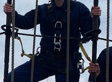
I finally finished updating my spreadsheets for the sizes and attachment points on each of the masts and yards, per the Eagle drawing. Besides the detailed dimensions of the masts and yards in the Eagle rigging drawing, two other key measurements are shown. 1. Mast rake (German: "mastfall") is specified for each of the three masts: Fore: 52mm per 1 meter Main: 70mm per 1 meter Mizzen: 87mm per 1 meter These convert to 3.0, 4.0, and 5.0 degrees respectively. Now I can accurately set the rake on each of the masts. My estimates based on photographs were in the ballpark, but nothing beats the design specs. 2. Standing rigging (wire) rope sizes. There are six different sizes listed on the drawing (50, 60, 70, 80, 90, and 100mm), the largest (100mm) for the fore and main topmast stays, and the smallest (50mm) for the mizzen upper backstay. The diagram also shows that the primary fore/aft stays for each mast are double ropes (which is evident in vintage and current photos). Now, are these figures diameters or circumferences? The main shrouds are listed as 90mm. If 90mm is a diameter, it converts to 3.50 inches in diameter. If 90mm is a circumference, it converts to 1.11 inches in diameter. Looking at a closeup of two cadets grasping the shrouds, I'd say the shroud diameter is almost certainly 1 inch rather than 3.5 inches (also note that the shrouds are served with small stuff; I'm not planning to model that). Rather than trying to scale and use six different line sizes, I'll use the two most prominent sizes, 70mm and 90mm, for all of the standing rigging. These scale (102.2) to .22mm (0.009 in.) and .28mm (0.011in) respectively, which seem considerably smaller than I would have expected. I'll address the sizes of running rigging later, but the above picture gives a clue as to the size of some of the lines (those pictured are clewlines and buntlines). Note how much smaller they are compared to the shrouds (half or less in diameter). I may need to re-think the scale size of lines for the standing rigging as compared with the running rigging. In any case, I plan to use black line for the standing rigging (rather than dark brown), and tan (or similar) for the running rigging. That's all for now. Lee