TimGee
-
Posts
6 -
Joined
-
Last visited
-
 TimGee reacted to a post in a topic:
1949 Chris-Craft 19' Racing Runabout by TimGee - Dumas - 1/8 scale
TimGee reacted to a post in a topic:
1949 Chris-Craft 19' Racing Runabout by TimGee - Dumas - 1/8 scale
-
Bryan Woods reacted to a post in a topic:
1949 Chris-Craft 19' Racing Runabout by TimGee - Dumas - 1/8 scale
-
gjdale reacted to a post in a topic:
1949 Chris-Craft 19' Racing Runabout by TimGee - Dumas - 1/8 scale
-
yvesvidal reacted to a post in a topic:
1949 Chris-Craft 19' Racing Runabout by TimGee - Dumas - 1/8 scale
-
ccoyle reacted to a post in a topic:
1949 Chris-Craft 19' Racing Runabout by TimGee - Dumas - 1/8 scale
-
I saw that you did a lot of internals before you closed up the hull on your build Grant. It was really impressive all around. I liked the prop upgrades and its brass strut in particular. I'm not going to put a motor or remote in my build however. It'll just be a mantel-queen for our lake house. Tim
- 8 replies
-
- 1
-
-
- Dumas
- Chris-Craft
- (and 1 more)
-
gjdale reacted to a post in a topic:
1949 Chris-Craft 19' Racing Runabout by TimGee - Dumas - 1/8 scale
-
king derelict reacted to a post in a topic:
1949 Chris-Craft 19' Racing Runabout by TimGee - Dumas - 1/8 scale
-
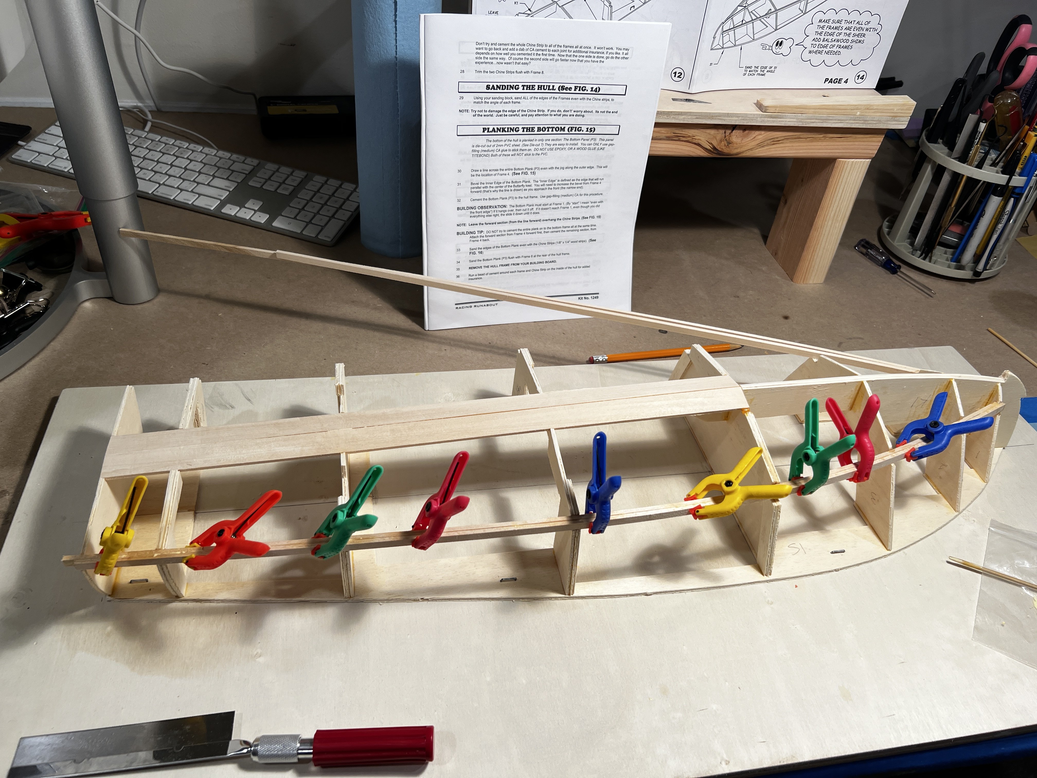
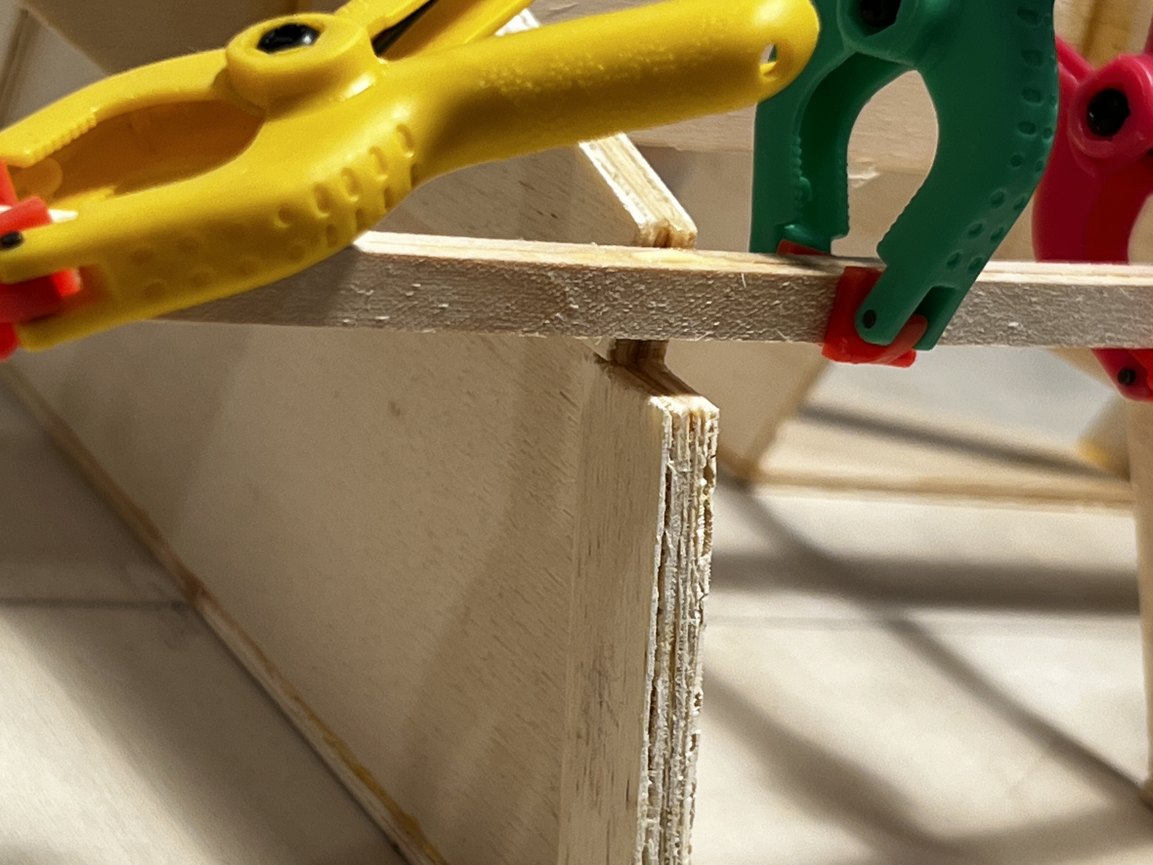
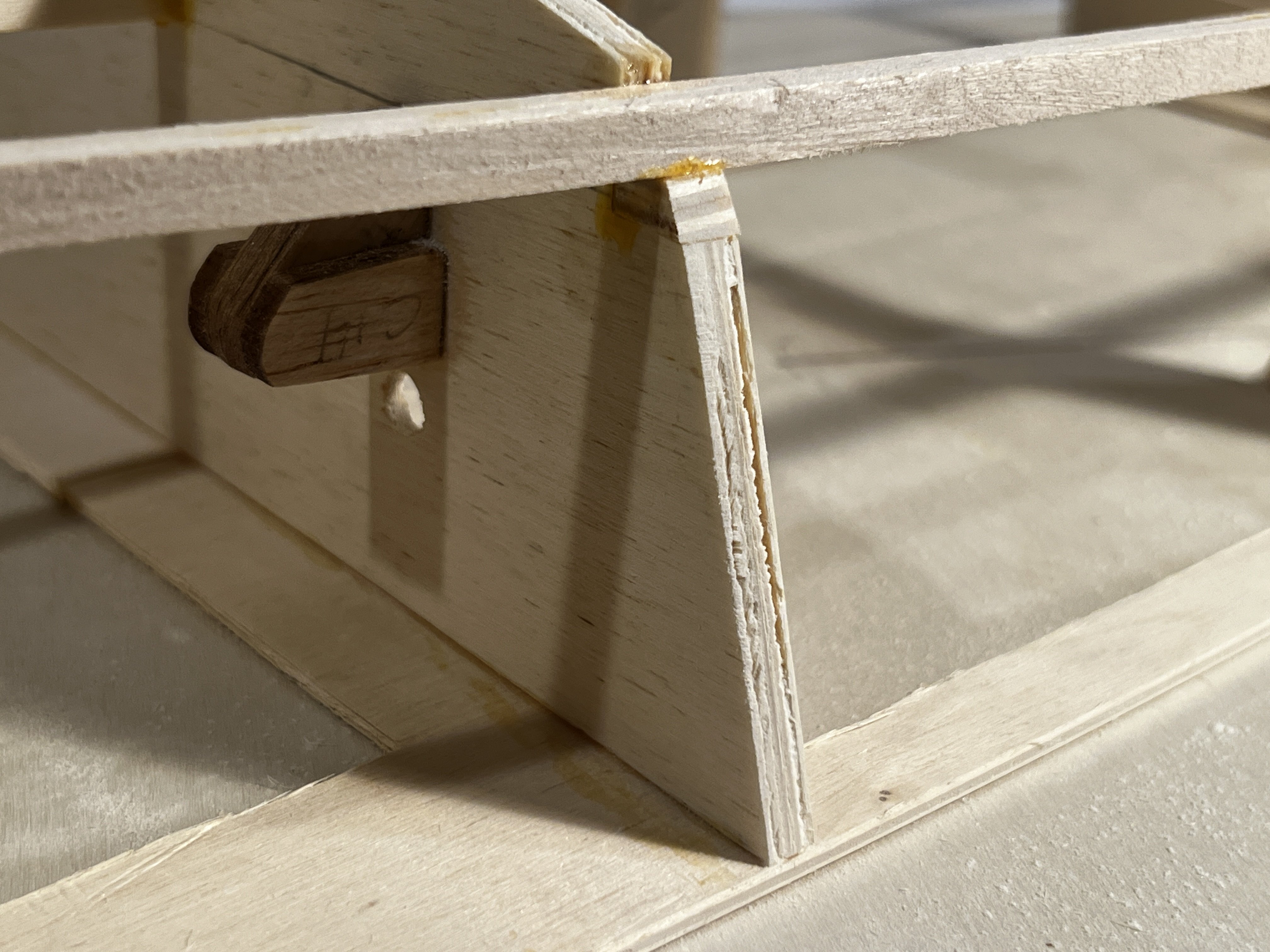
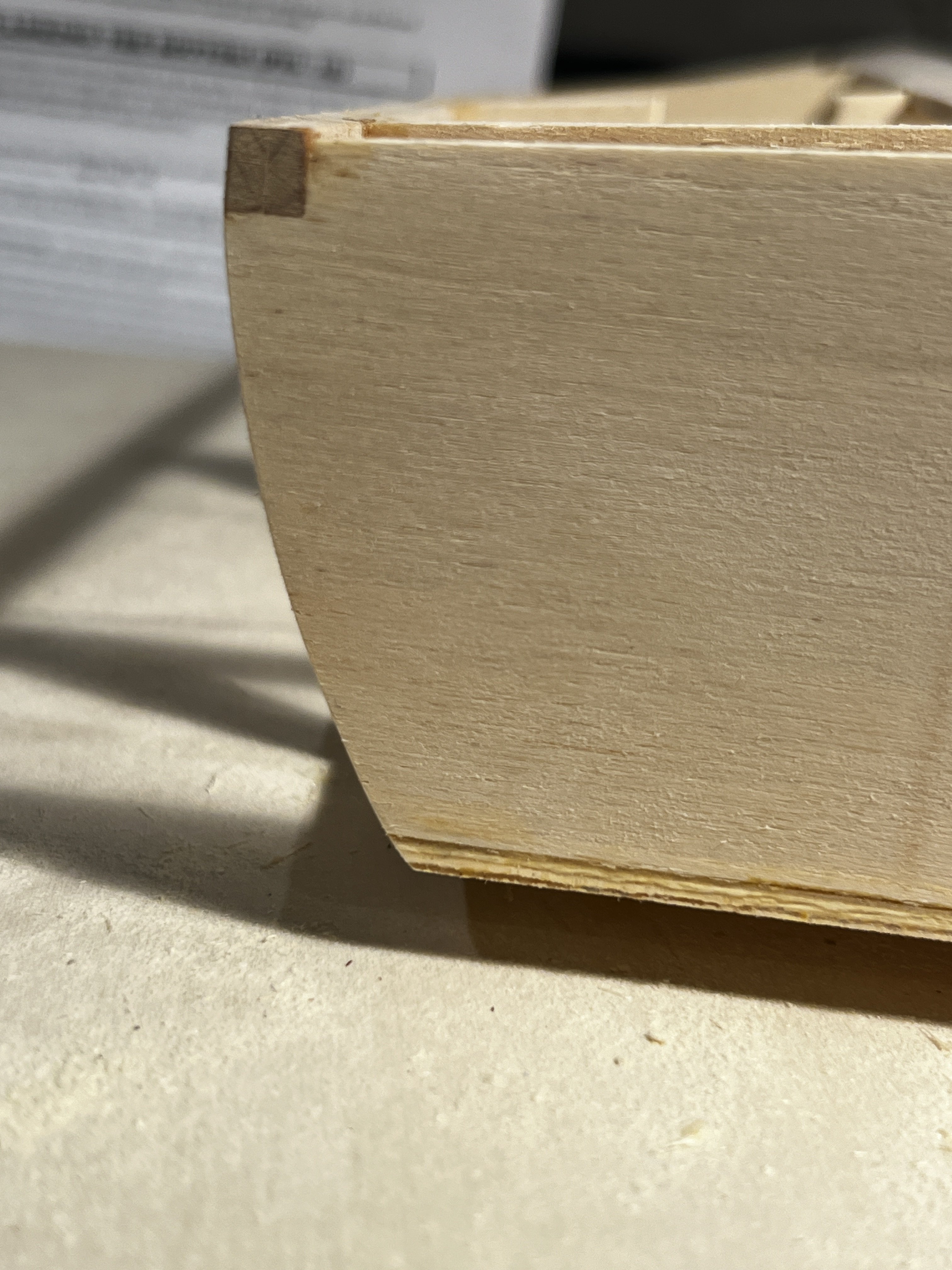
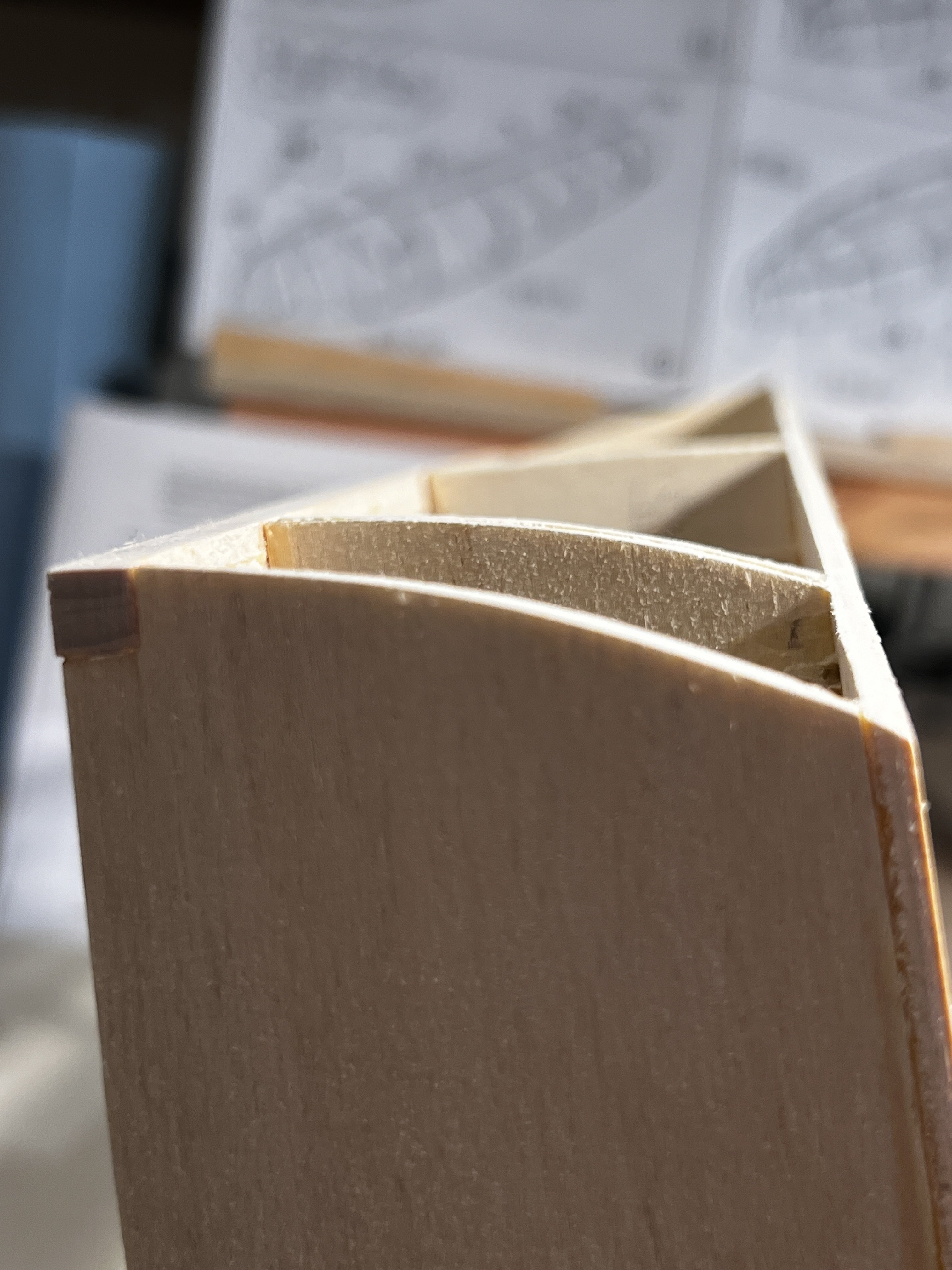
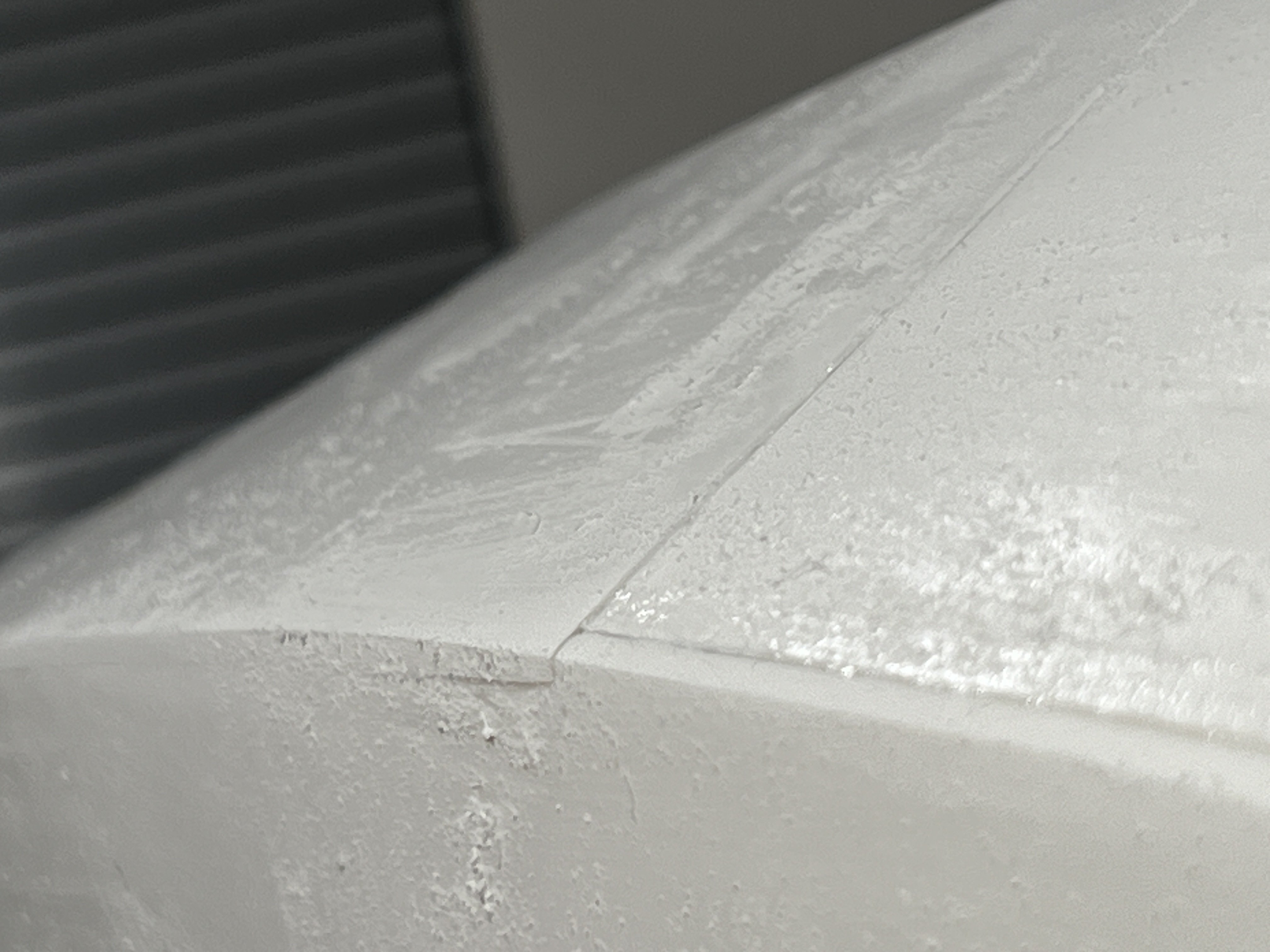
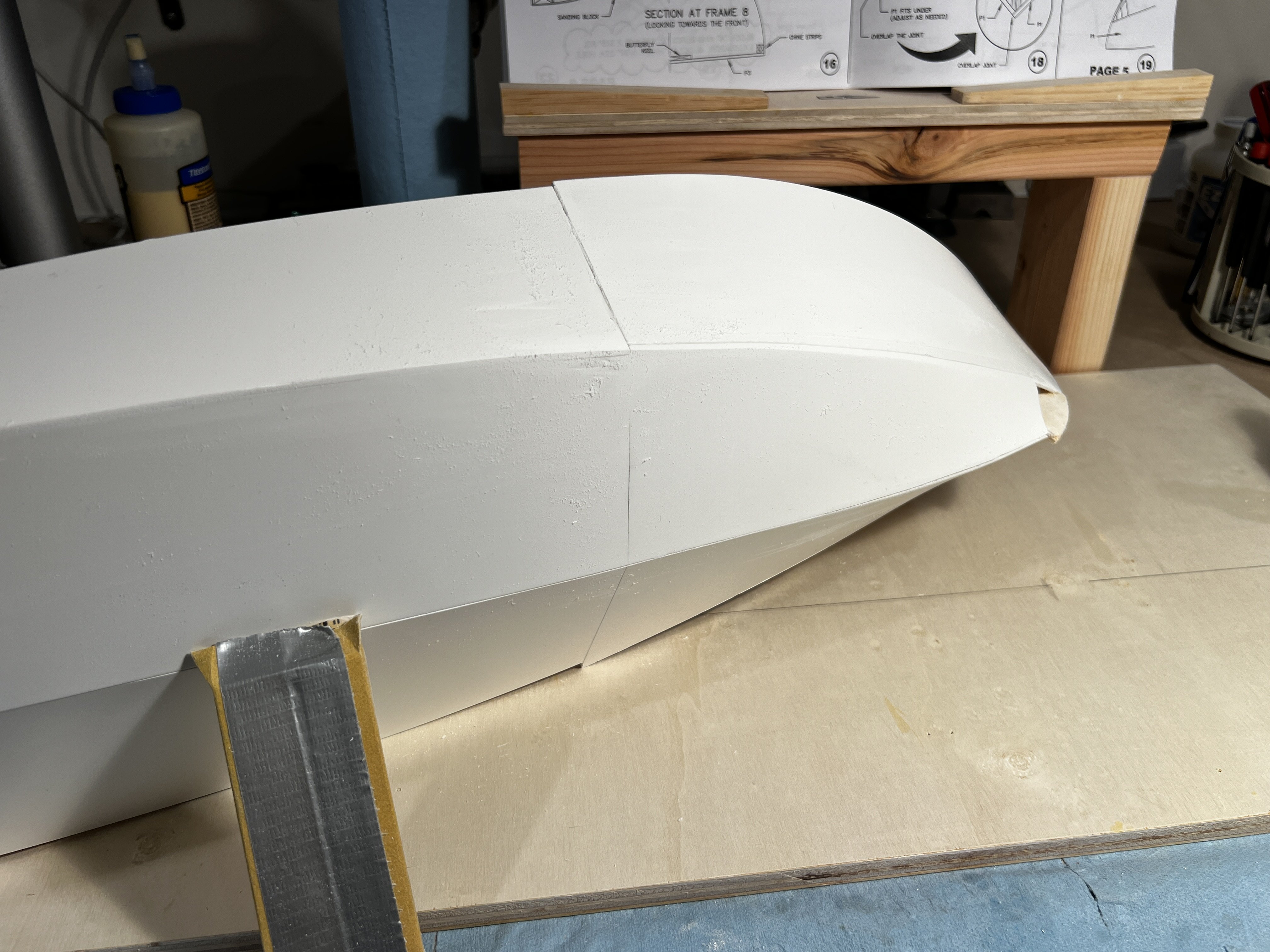
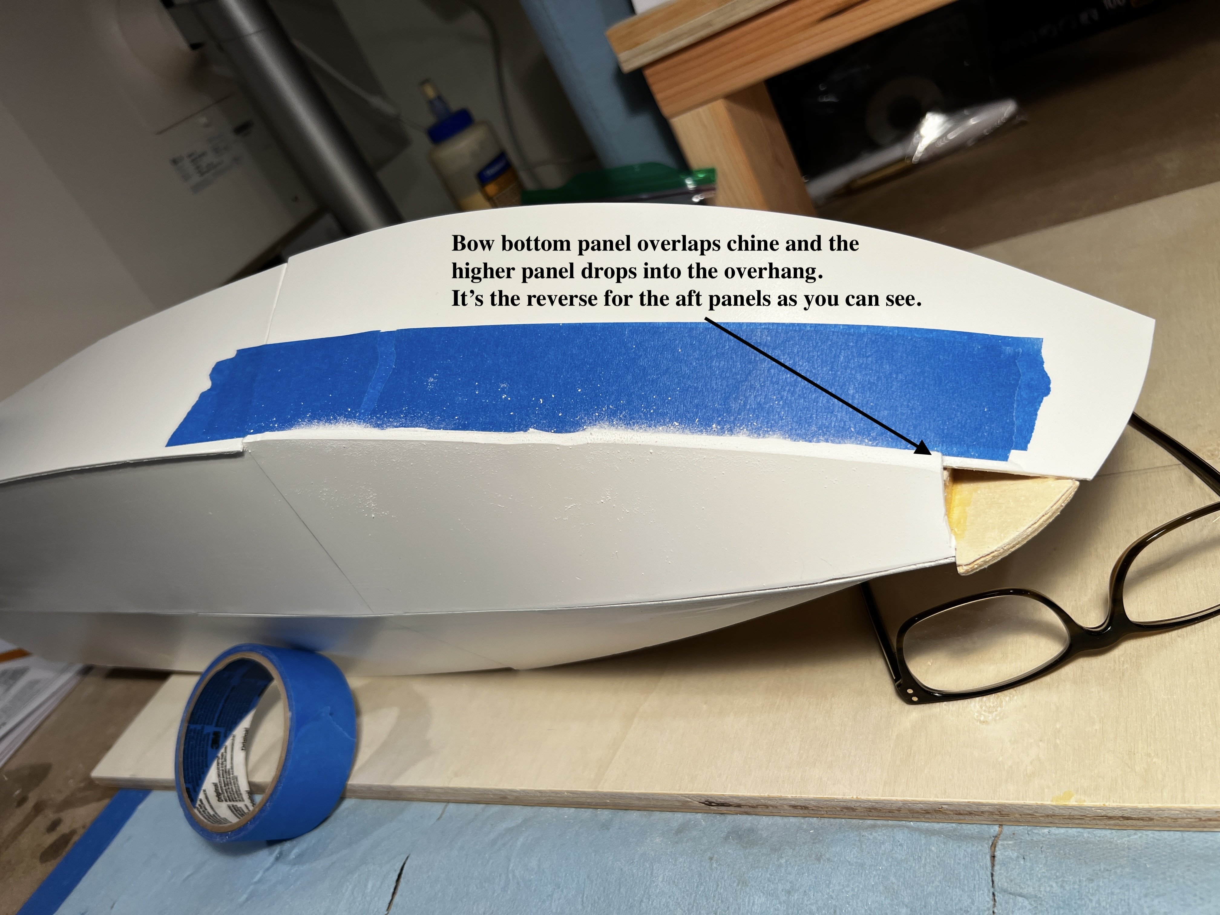
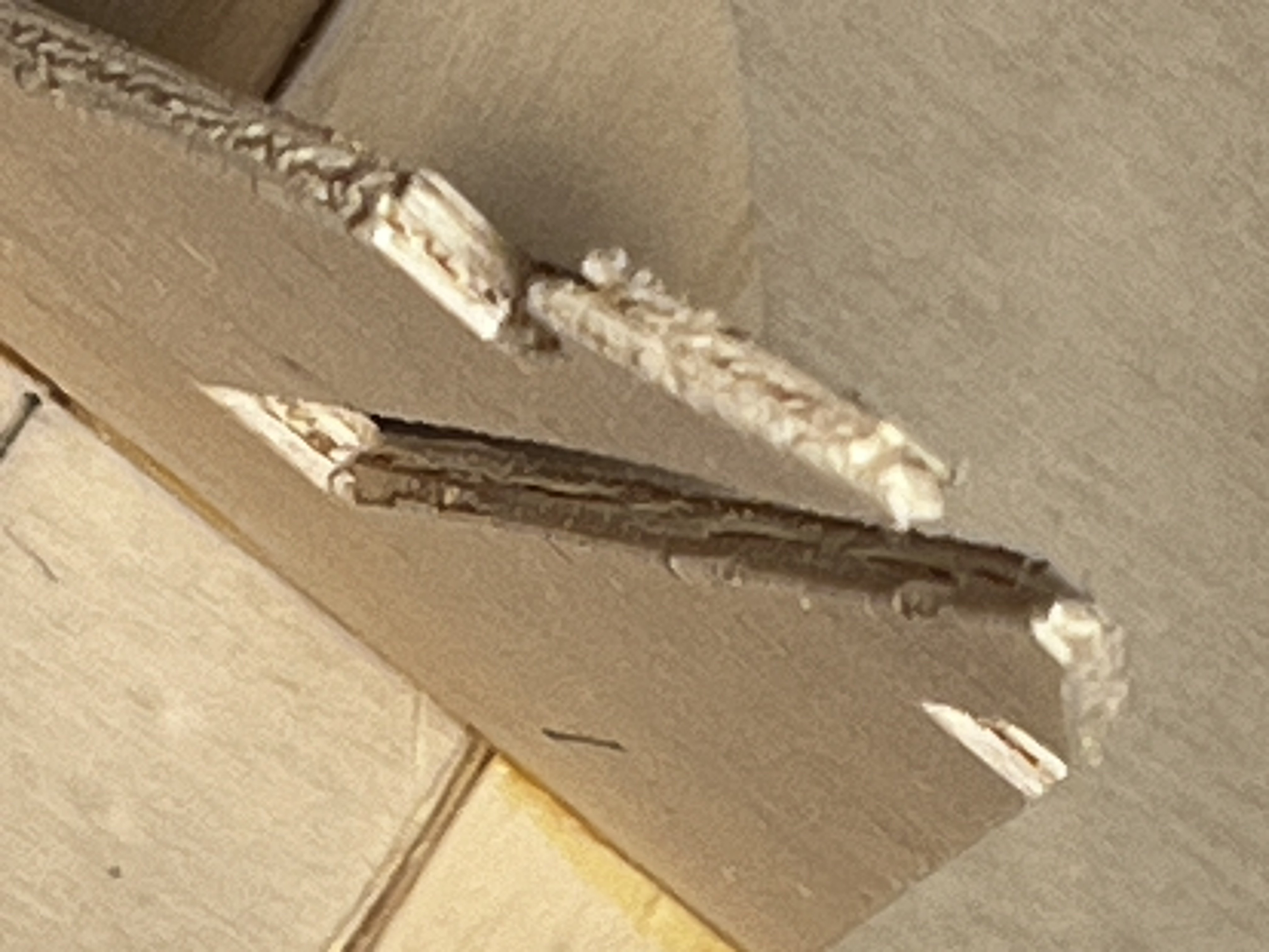
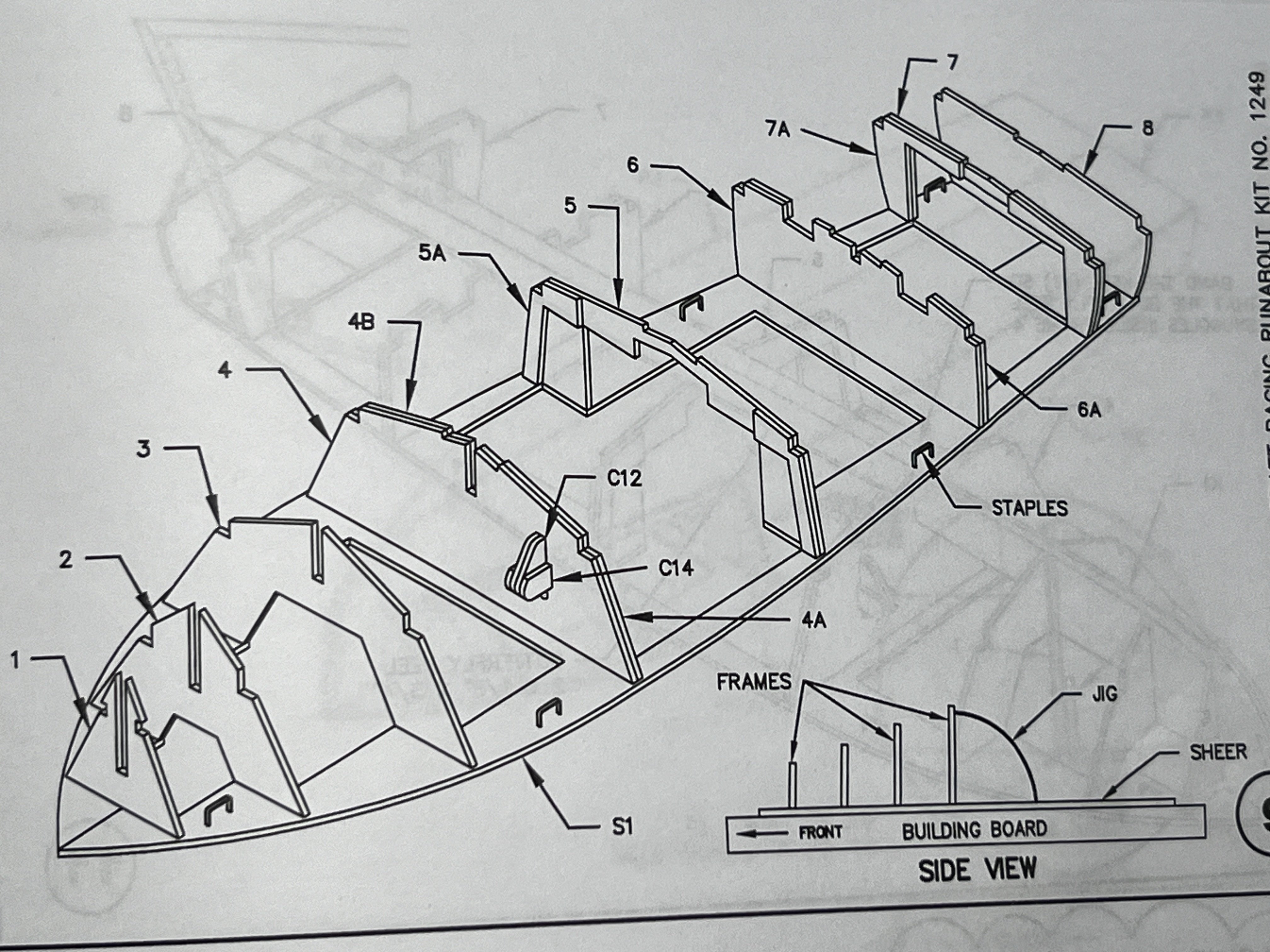
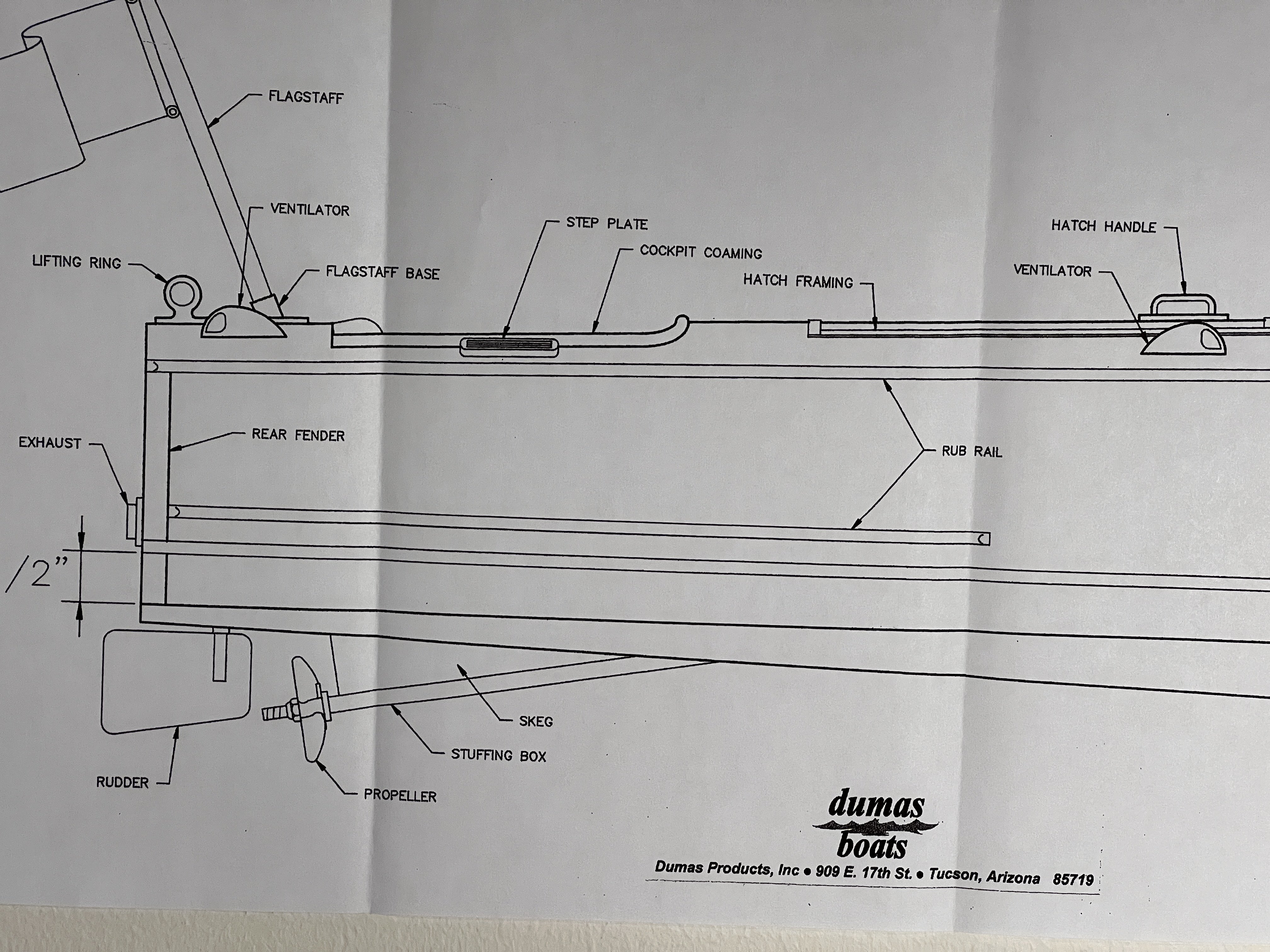
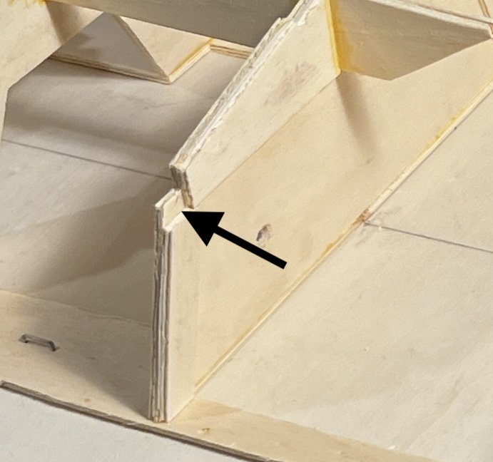
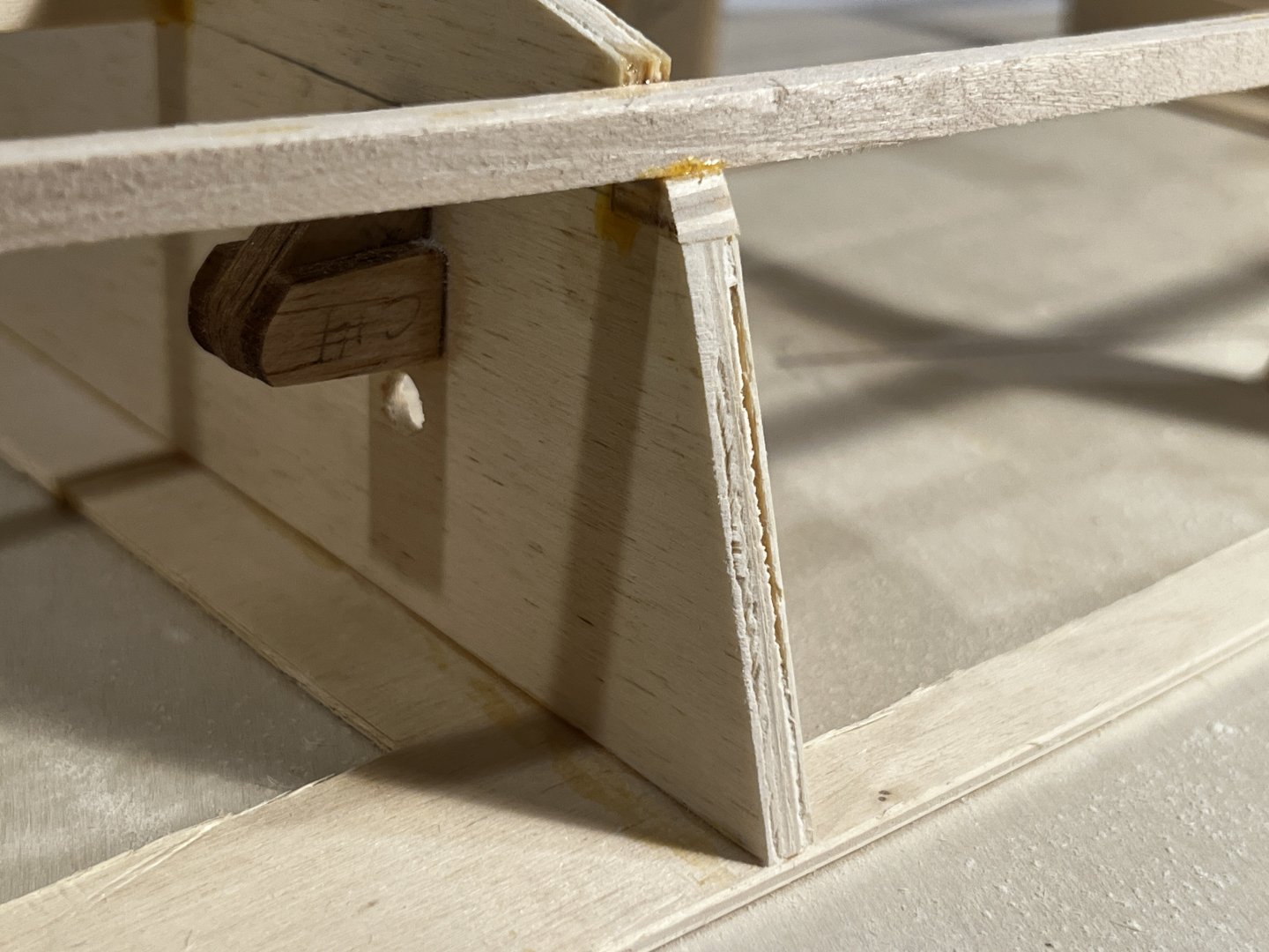
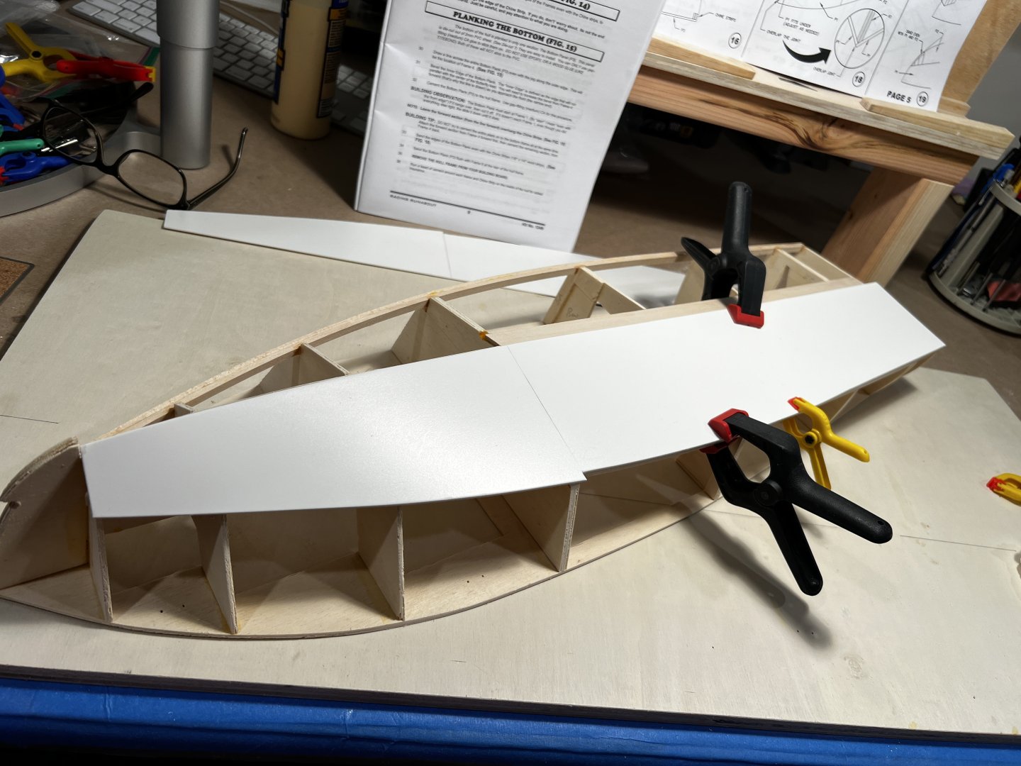
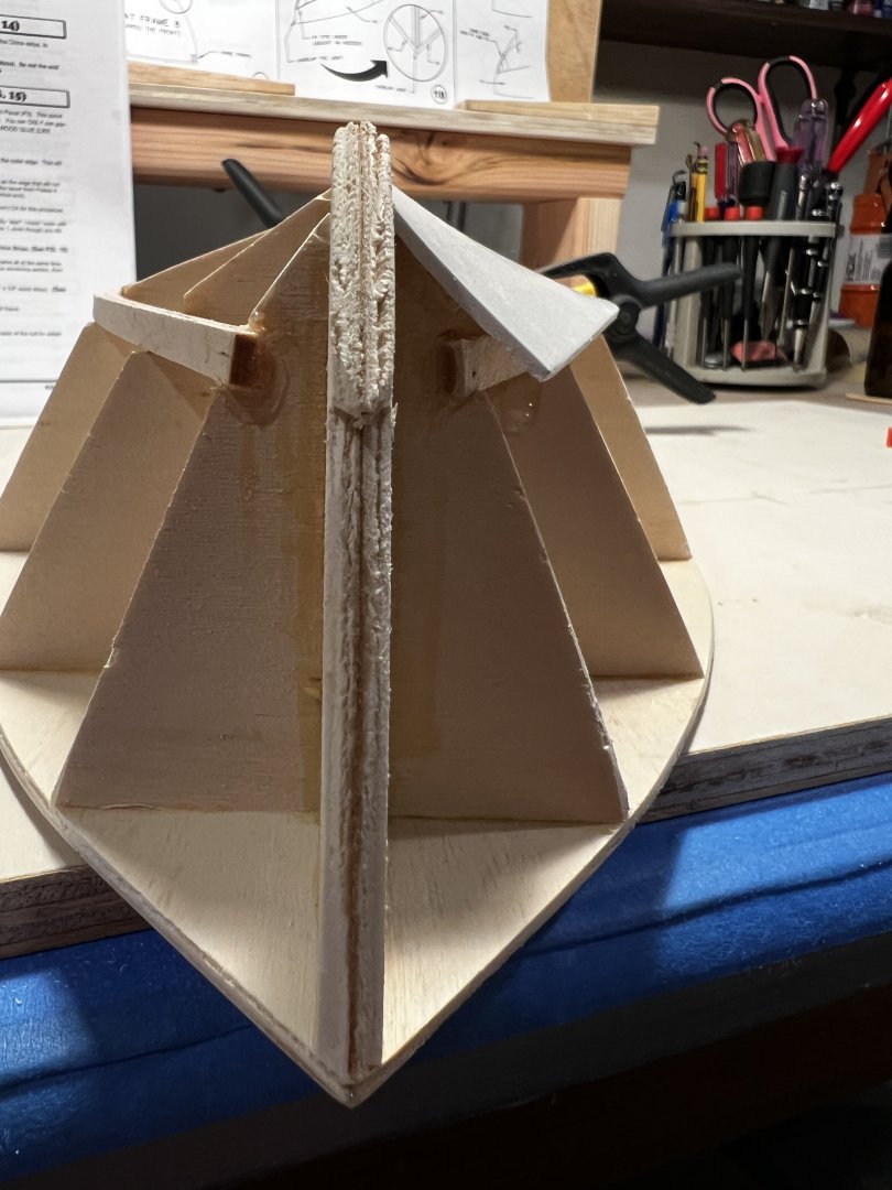
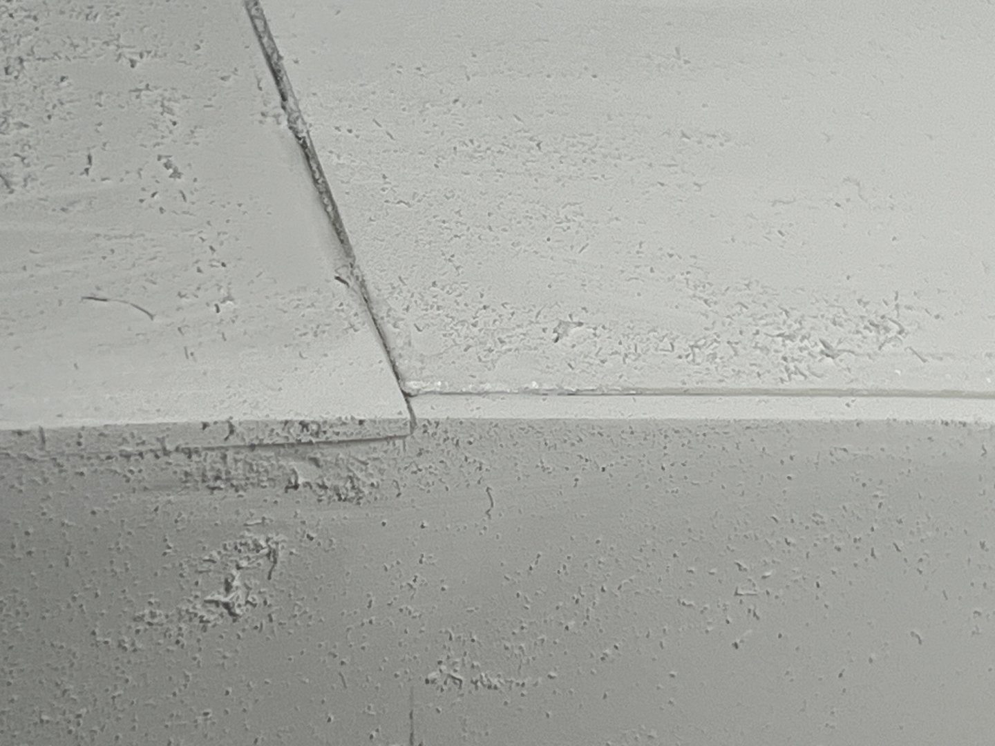
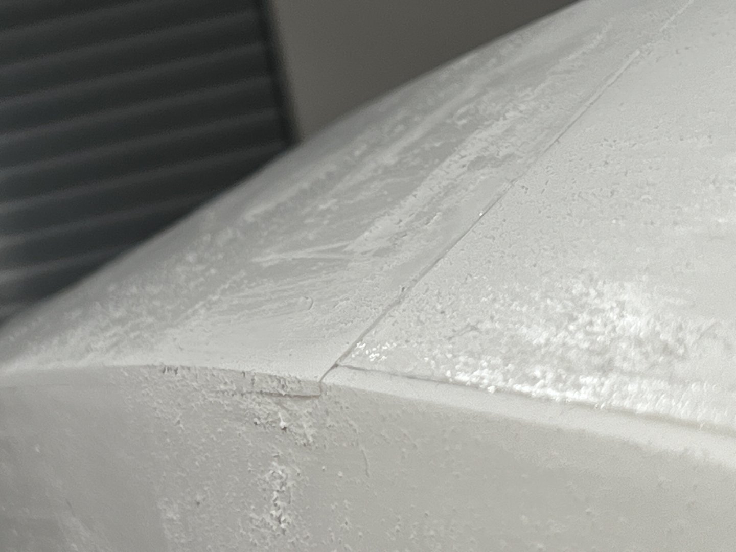
I made some progress over the week. Now that the frames are in the next step is to glue in the chine. It's made of two 1/4" x 1/2" basswood strips. This step was my first mistake. The directions say to glue the strips together but then later say to only glue the 1st 1/4" of the strips together. Since the strips have to follow the curve of the chine the outer strip will be slightly longer so the strips need to adjust in relationship to each other as you glue them up. So, only glue the first 1/4" of them together until you glue them to the frames. Another thing that was a head scratcher was that frame number 4 is built with a notch to accept the chine. When you sister up the sub frame 4A, the corresponding notch is only half the depth: Mistake #2. I trimmed the notch to the greater depth thinking that the chine would nest in there. As I placed the chine into the other frames' notches it became clear that the notch that I expanded was too deep and the true support for the chine was what I cut away. I ended up building a shim and it worked just fine: At this point you pop the build off the board and it's important to make sure that the sheer and keel are following the lines of the frames. With a bit of sanding you can start fairing out the pieces: Looking at the whole sheer (subdeck) is a good way to make sure you're balanced with the sanding you've done and that the curves and thicknesses are equal to port and starboard: Next step is putting the PVC panels on the frames. There are 6 of them. Two create the bottom of the hull below the waterline. The four others form the underplanking above the waterline. This isn't easy. The PVC resists bending and there's a lot of pressure as you try to glue the pieces down. I used medium CA glue and a lot of it! One piece of advice that I learned only after the fact came from gjdale's build log. He suggested using a heat gun to form the PVC panels to the proper shape. I managed to just clamp some and just hold the rest by hand: The bottom pieces are challenging towards the bow as the twists and angles are pretty severe. I had to spend a lot of time cutting, sanding and doing the best I could to angle the edges to mate up properly. Once the dry fits were acceptable I held many glue ups by hand and used a bit of kicker to set the CA glue when I could. Many of the panels failed to adhere the first time but after applying glue again they held. This is looking to the stern with the forward most panel attached to the first frame of the keel. Notice that the panel overlaps the chine strip. The side panel will drop into the overlap and fill it: And here's the side panel in place. I used painter's tape to protect the upper panel as I sanded the seam to the correct angle. The placement of these PVC panels was a source of confusion to me. The directions aren't totally clear about the overlaps but just remember that the aft side panel overlaps down over the bottom panel. The bow panels do the opposite - the bottom overlaps the chine going towards the deck and the side panel tucks into the overlap. After a bit of sanding the fore and aft sections create a unified chine that travels naturally bow to stern: 1st side glued up. At this point it's pretty rough but I'm satisfied with the result. I'm confident that it will create a nice, consistent chine line once filled, sanded some more and painted. The curve of the hull is pleasing and the PVC panels create a nice line.


- 8 replies
-
- 5
-
-
- Dumas
- Chris-Craft
- (and 1 more)
-
yvesvidal reacted to a post in a topic:
1949 Chris-Craft 19' Racing Runabout by TimGee - Dumas - 1/8 scale
-
gjdale reacted to a post in a topic:
1949 Chris-Craft 19' Racing Runabout by TimGee - Dumas - 1/8 scale
-
Rustyj reacted to a post in a topic:
1949 Chris-Craft 19' Racing Runabout by TimGee - Dumas - 1/8 scale
-
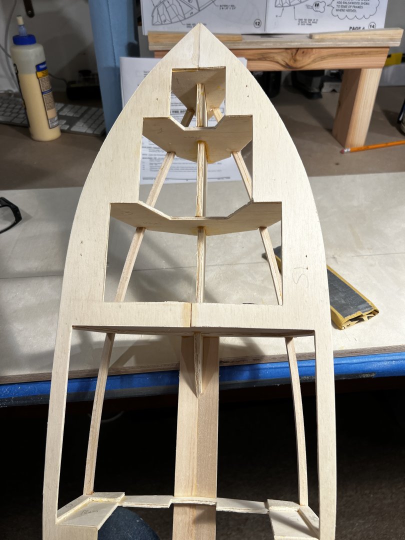
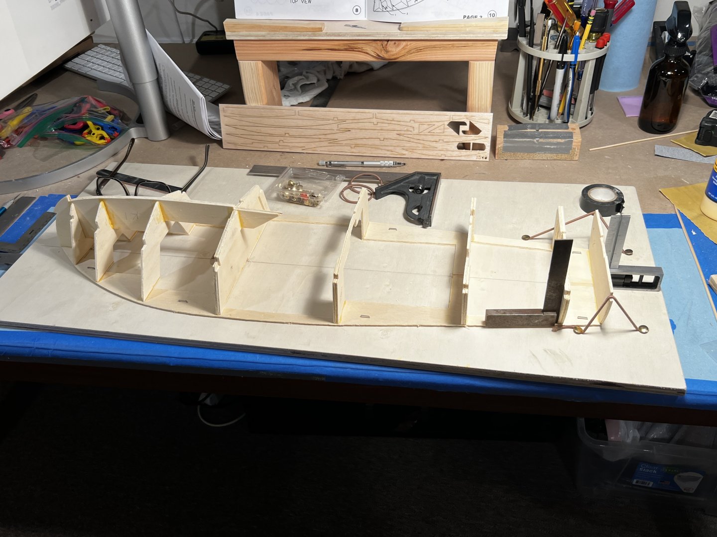
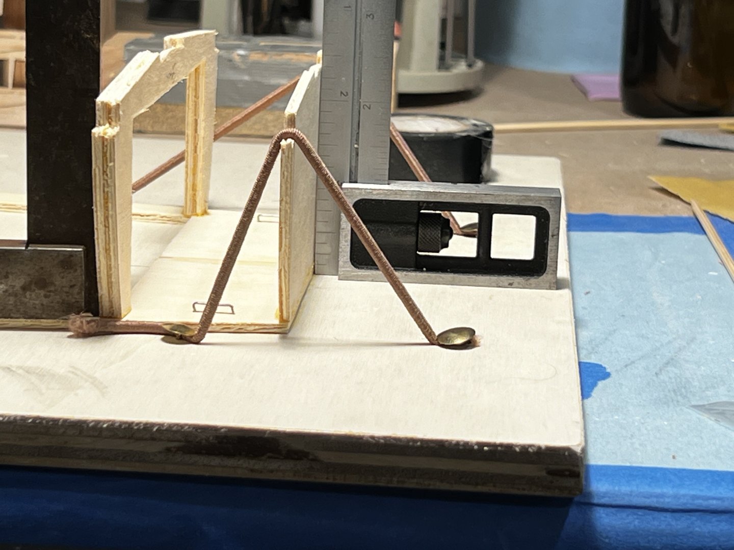
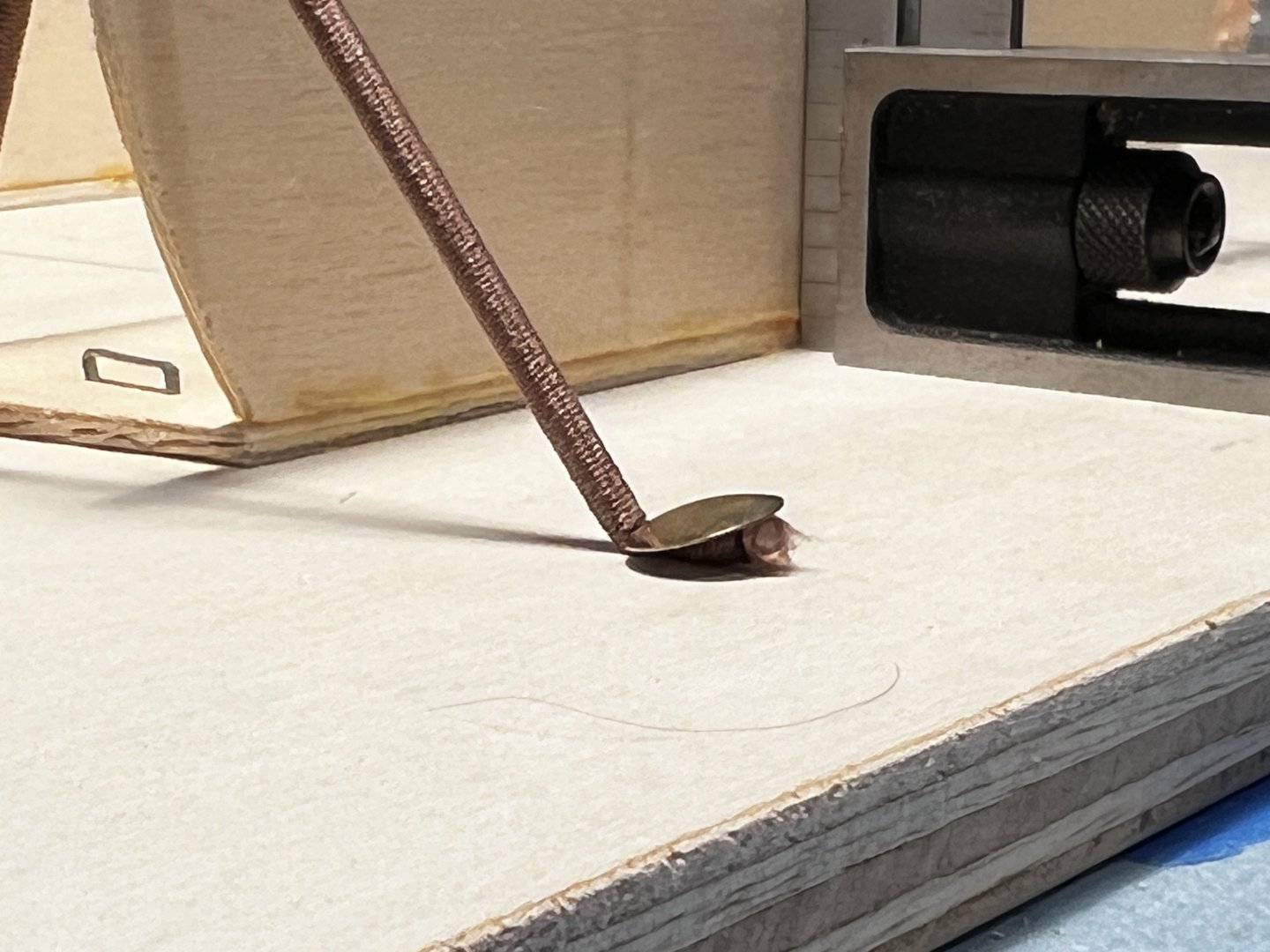
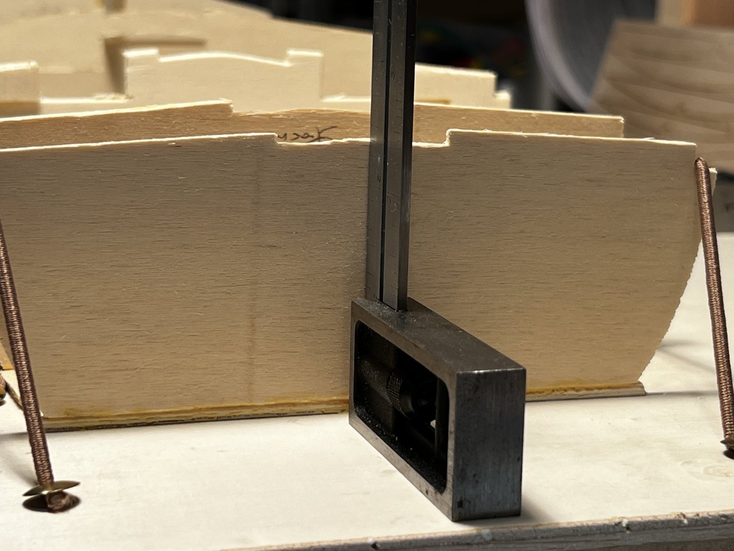
Finished the frames and I decided to keep frames 5-8 square to the sheer. I added some more white glue to the joints to strengthen them and it looks good to me: One thing I'm excited by is using hair ties and thumb tacks to add some downward force on the frames as they glue up to the sheer. It worked really well: It a very light tension. I suspect that I may be re-inventing the wheel here and this is an old trick in model building but it's new to me. I discovered that if you position the hair tie fore or aft you can get it to be flush with the square. Tim
- 8 replies
-
- 3
-
-
- Dumas
- Chris-Craft
- (and 1 more)
-
Thanks Grant. I will check that out. Tim
-
yvesvidal reacted to a post in a topic:
1949 Chris-Craft 19' Racing Runabout by TimGee - Dumas - 1/8 scale
-
This helps tremendously. Thank you. I really wanted to get the the hull shape right so I'm glad I asked. Thank you Rusty. Tim
-
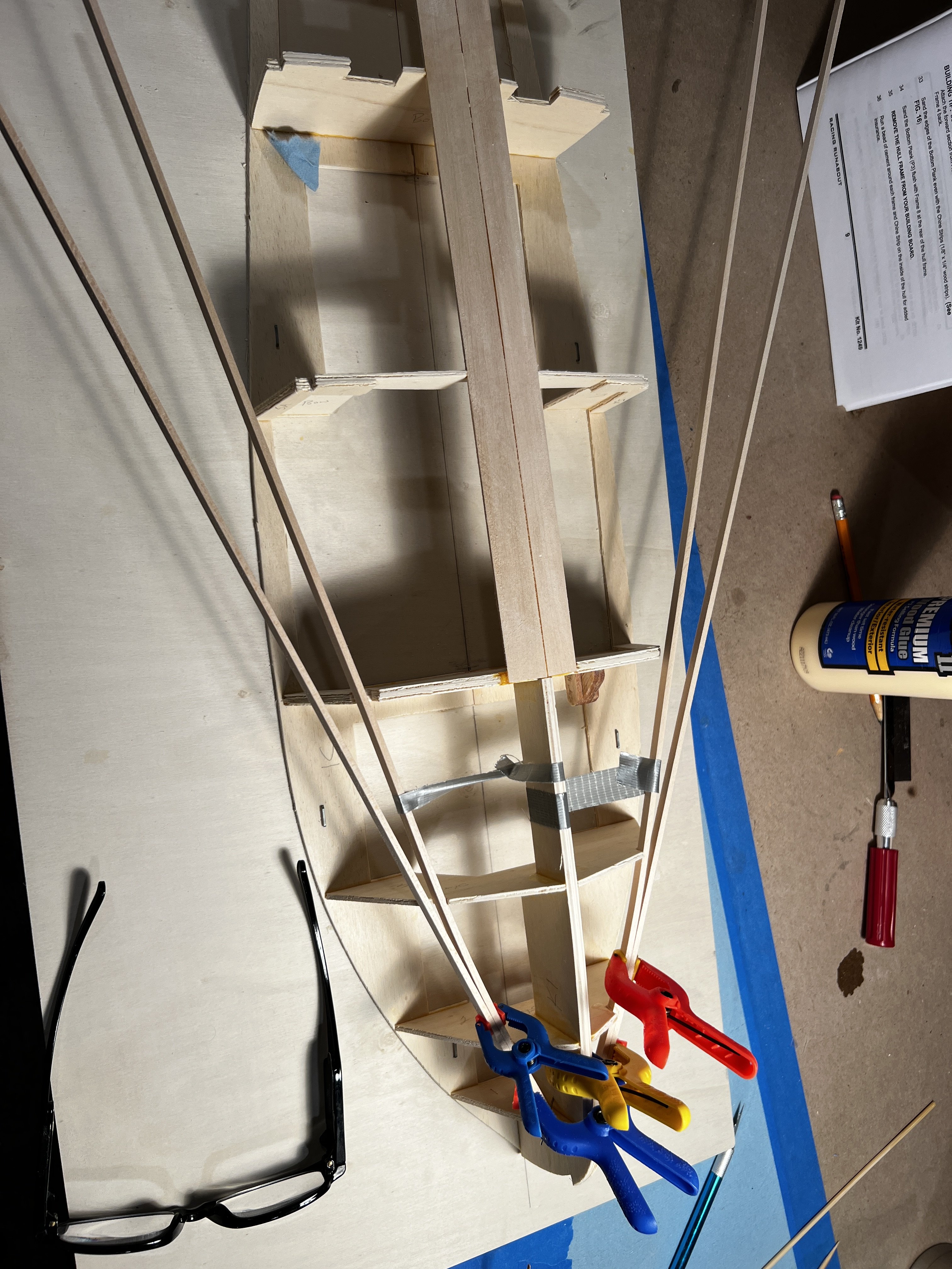
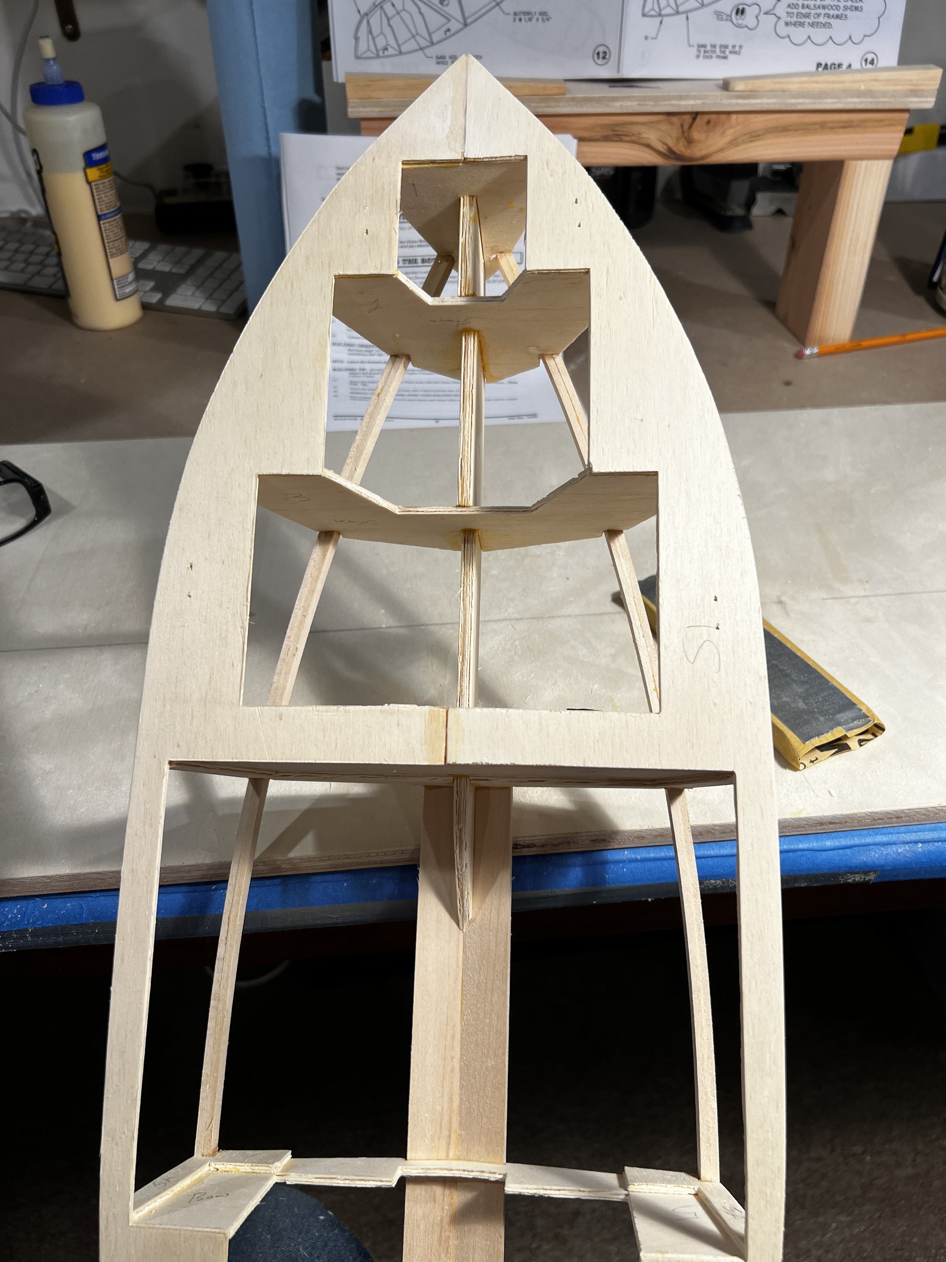
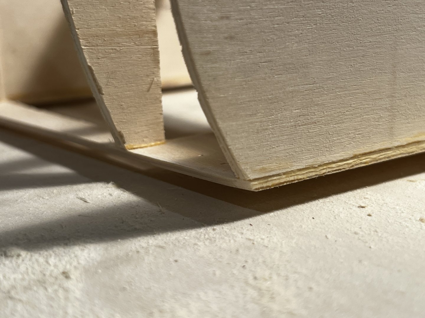
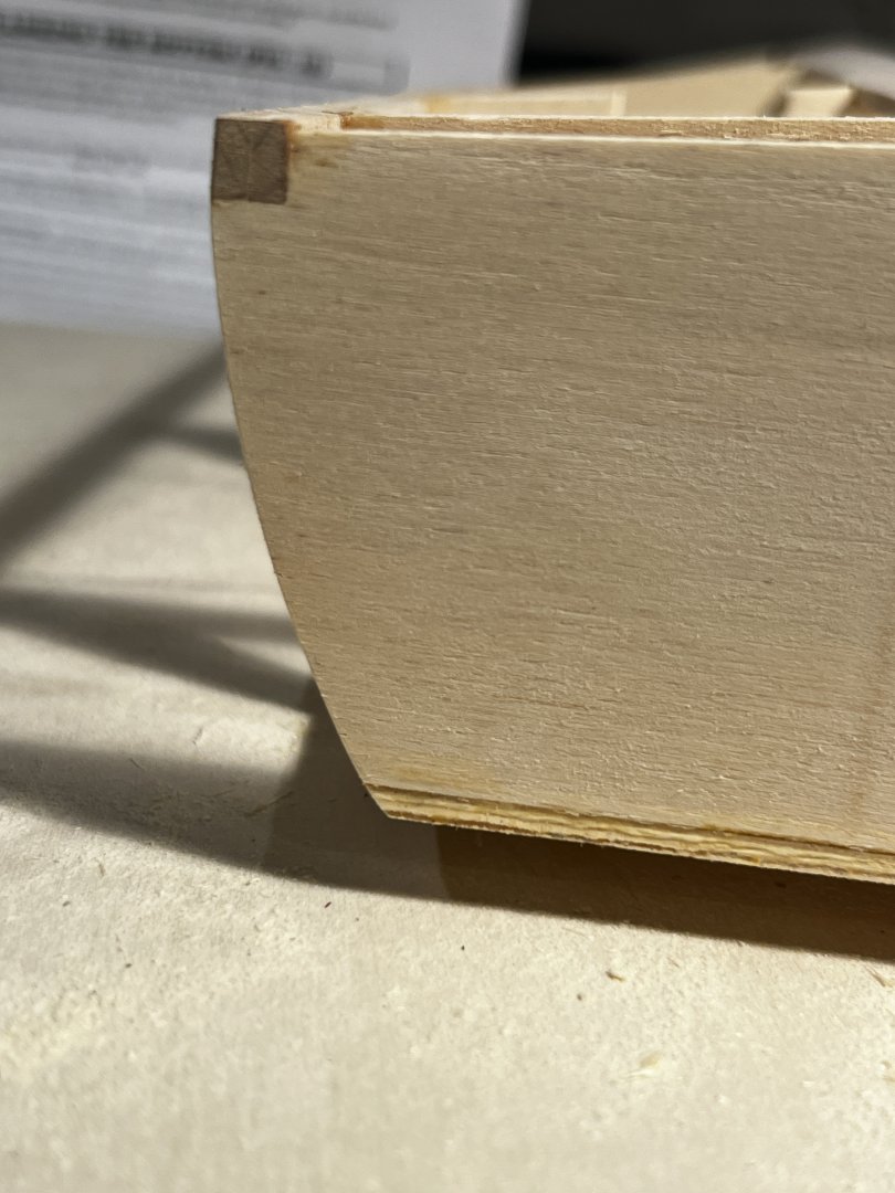
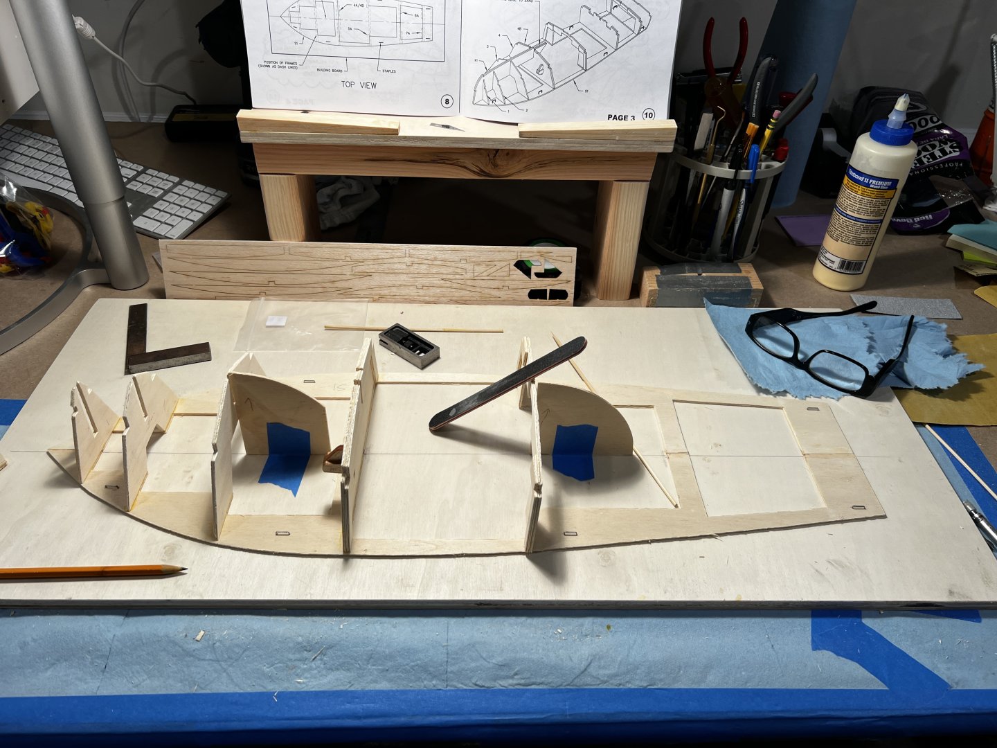
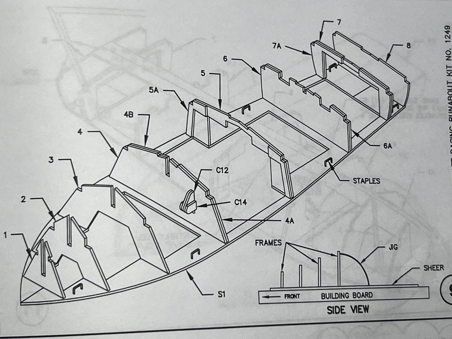
Hello all, New member here. My first build was a year ago. It was the Tippecanoe T27. That's was a fun kit and a good introduction to the hobby. I've also just completed a 14' real (1:1 scale) stand up paddle board that I finished this summer. That was a monster project that took me 2 years. Now I'm working on my second model build. It's the Dumas 1949 Chris-Craft 19' racing runabout in 1/8 scale. I've just started and I'm just building out the frames onto the sheer. I thought I'd introduce myself with a few pictures as I go through this build and ask a question or two in the process. I've found the frames to be a bit rough. They are die-cut and the end grain is a bit punky which makes for some questionable glue joints even when they are sanded. There's a lot of air in that end grain! I'm thinking of building up the joints with some medium viscosity CA glue. One question I have is an issue I'm having with the final frames going aft. There is a jig that gives the frames a slight cant to the aft. You can see it in the first image above. It's the 1/4 circle taped down with blue tape. The instructions say you should use this for all of the frames (1-8) but the insert figure shows the first 4 frames at the bow only. (The side view insert in the following image) My concern is that it doesn't seem like the remaining frames need the cant aft. Especially the transom frame which looks dead square in the full scale rendering. It's a bit of a head scratcher as the instructions clearly state: "Cement Frames 1, 2, 3, 4, 5, 6, 7 and 8 to the Sheer. Use the jig provided to get the proper angle to each frame. . . . . Go look at the 'side view' drawing of figure 9 if you are confused. " Any thoughts on this? The side view only shows the first 4 frames and those are also the only frames that accept the keel. It makes sense that those would be canted to accept the keel but my instinct is that the remaining frames should be square to the sheer. Please let me know if anyone has some insight into this. Thank you in advance for the advice. I'll be posting my progress as time allows. Tim

- 8 replies
-
- 2
-
-
- Dumas
- Chris-Craft
- (and 1 more)