Argaen Lok
-
Posts
41 -
Joined
-
Last visited
-
 RossR reacted to a post in a topic:
US Brig Syren by Argaen Lok (aka Scott Larkins) - Model Shipways - Scale 1:64
RossR reacted to a post in a topic:
US Brig Syren by Argaen Lok (aka Scott Larkins) - Model Shipways - Scale 1:64
-
RossR reacted to a post in a topic:
US Brig Syren by Argaen Lok (aka Scott Larkins) - Model Shipways - Scale 1:64
-
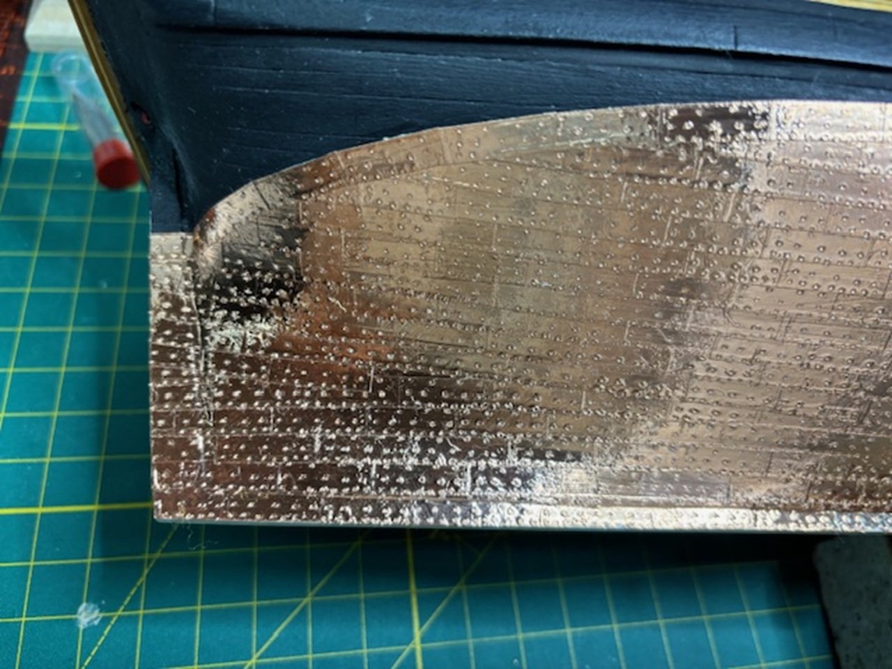
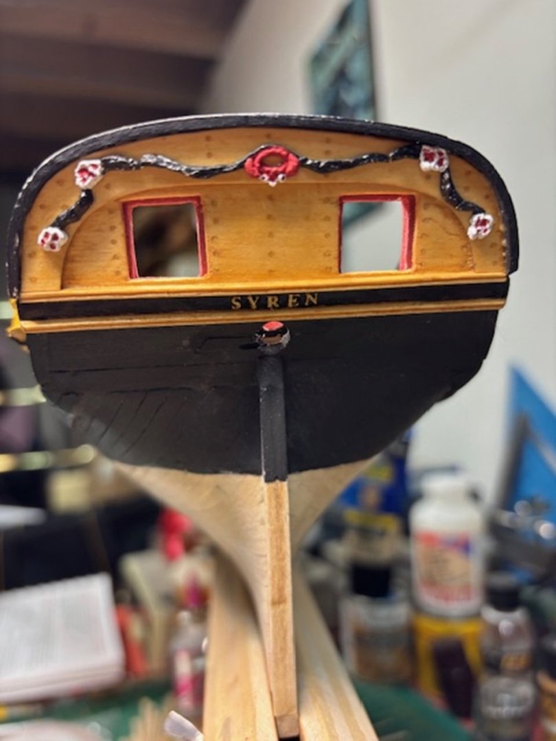
 Did a little extra work on trying to smooth out some of the wrinkles last night. I succeeded with that but also smoothed down the nail marks. I think it looks a bit better now. My coppering doesn't make my ship looks like it's suffering from a skin condition now. Not good as overworked copper work, but if I get the chance to building another coppered ship, I can make improvement. I hope.
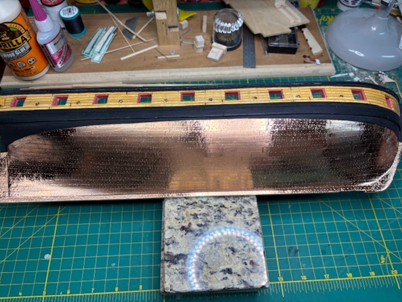
-
PaddyO reacted to a post in a topic:
US Brig Syren by Argaen Lok (aka Scott Larkins) - Model Shipways - Scale 1:64
-
palmerit reacted to a post in a topic:
US Brig Syren by Argaen Lok (aka Scott Larkins) - Model Shipways - Scale 1:64
-
Ryland Craze reacted to a post in a topic:
US Brig Syren by Argaen Lok (aka Scott Larkins) - Model Shipways - Scale 1:64
-
Gaffrig reacted to a post in a topic:
US Brig Syren by Argaen Lok (aka Scott Larkins) - Model Shipways - Scale 1:64
-
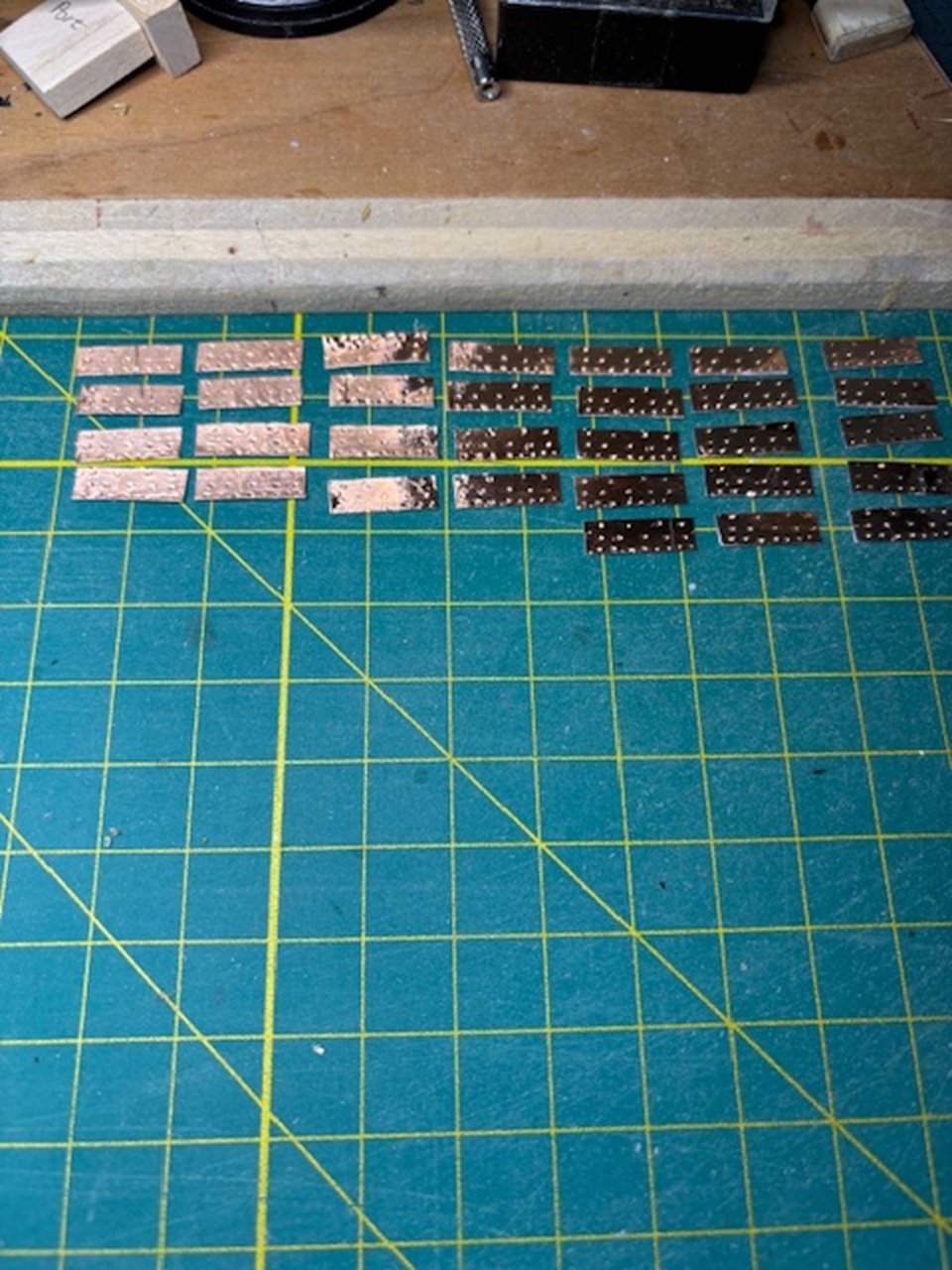
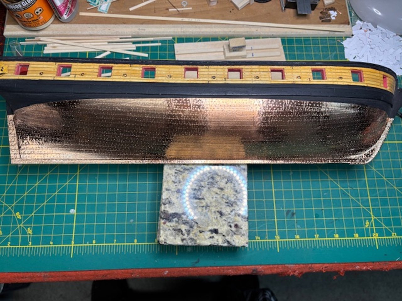
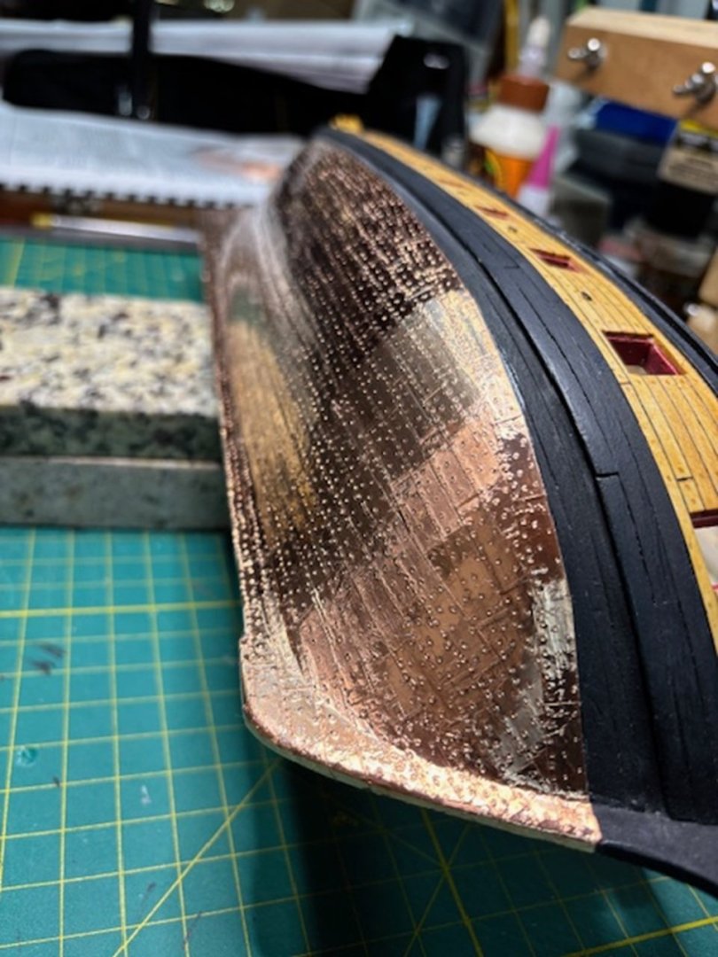
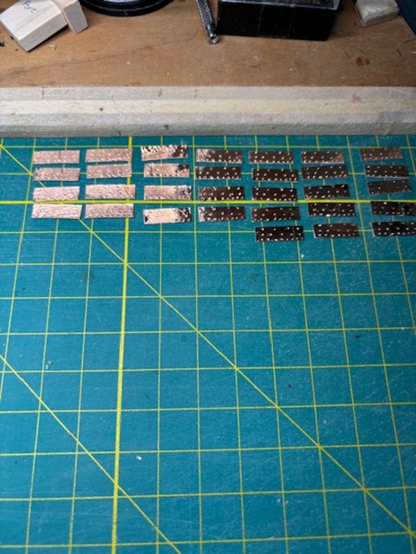
Making some progress. Took me a few weeks but the coppering of the starboard side of the ship is now complete. A few lessons from this process I can pass along. I used two pairs of tweezers to apply each copper plate, one for each hand. I was trying to keep as little finger, and thus finger oils, off of the copper. The recommended 1/64 overlap was not always perfect and sometimes a row or two might get a little wavey. But as long as the wave is not too extreme, I was able to make up for it and smooth it out on the next layer up. But the one layer, the last top layer up against the painted water line must be perfect as anything against the black background will be very apparent. The other area, which the instructions did not cover, is the wrap over at the bow and stern. At the moment, I just wrapped any piece over to the other side. Since the bow is so thin, I'm betting anyone looking at it won't notice any layering issues. As for the stern, it's going to be covered over by the rudder, and no one is going to see that for sure. So maybe it's no big deal. We'll see. It took me 411 individual plates, which equated to 25 linear feet of copper ribbon. Way more than I would have expected. Since this is my first coppering build, I guess I shouldn't have too many expectations. I would also say that putting on the sanding sealer was a great help. The little adhesive plates held so much better than if I hadn't done it. Make sure you do. The little extra work to apply and sand two coats is so worth it. Anyways, see the pics below. Yes, the copper is very shiny and bright but I'll look into doing a slight weathering technique to make it a tad bit duller, and thus a little bit more realistic.
-
Argaen Lok reacted to a post in a topic:
US Brig Syren by Argaen Lok (aka Scott Larkins) - Model Shipways - Scale 1:64
-
Coyote_6 reacted to a post in a topic:
US Brig Syren by Argaen Lok (aka Scott Larkins) - Model Shipways - Scale 1:64
-
PaddyO reacted to a post in a topic:
US Brig Syren by Argaen Lok (aka Scott Larkins) - Model Shipways - Scale 1:64
-
CiscoH reacted to a post in a topic:
US Brig Syren by Argaen Lok (aka Scott Larkins) - Model Shipways - Scale 1:64
-
RossR reacted to a post in a topic:
US Brig Syren by Argaen Lok (aka Scott Larkins) - Model Shipways - Scale 1:64
-
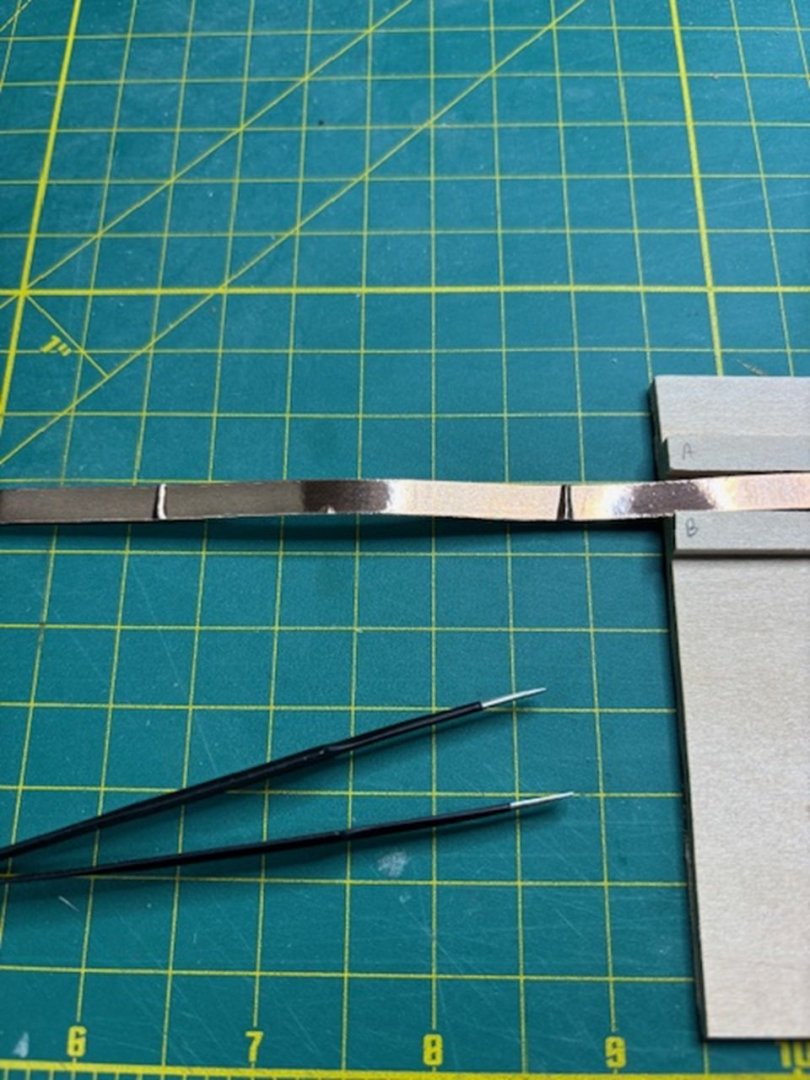
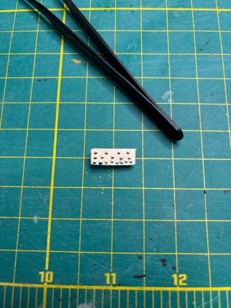
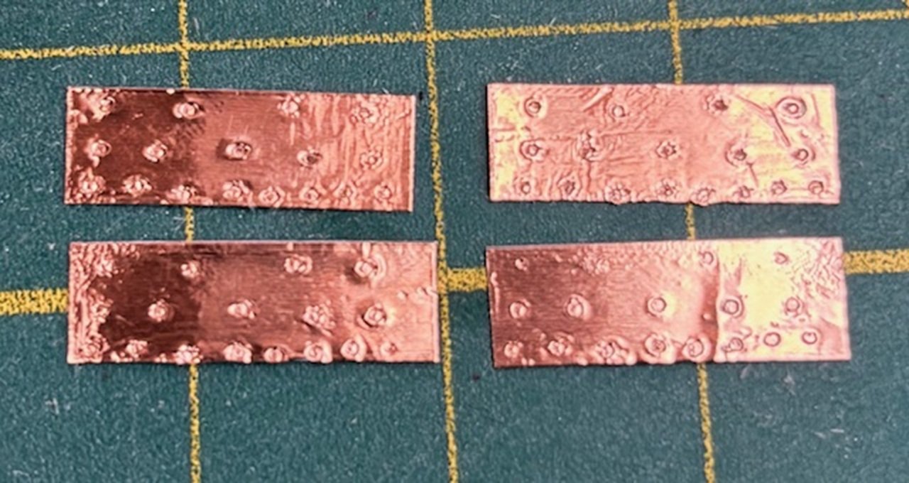
Okay, tried that new copper jig last night. I did come across a new issue for anyone following along. The copper strip is having some unwanted kinks as I'm unrolling it to put through the jig. I didn't think the copper tape was so thin, that this would happen. See below. Not sure what I can do other than maybe unroll more of the strip before I cut off the suggested 12-inch sections. We'll see. Below is my first pressed and cut plates from my first strip. Not too bad actually. I think I can get away with just pressing the pins down by hand instead of using a hammer as per the instruction's suggestion. I found, obviously, if I got too heavy handed, I was punching through the thin copper foil. I also used a scrap piece of wood strip to smooth out the copper side of the strip. I didn't exactly "burnish" to copper as per instructed, but I think this worked. I'm trying to keep my fingers off of the copper. I need to get some thin gloves. Otherwise, all of this work will be done using two tweezers. Oops. Hope people following along can learn from my booboos.
-
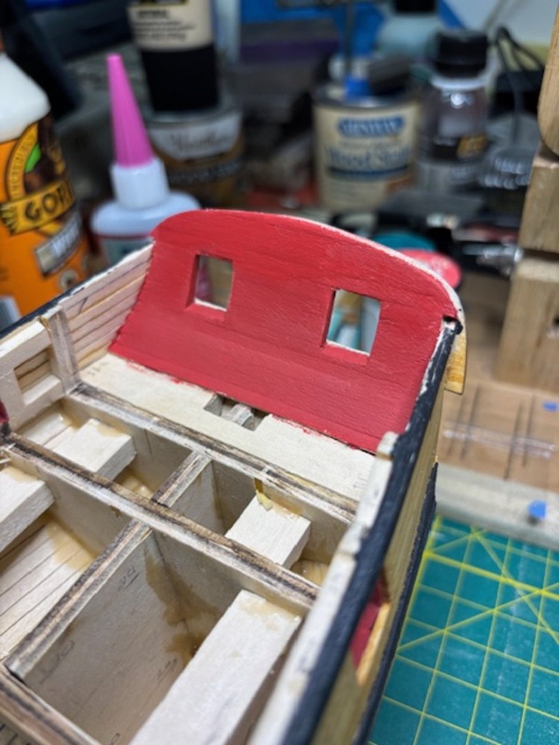
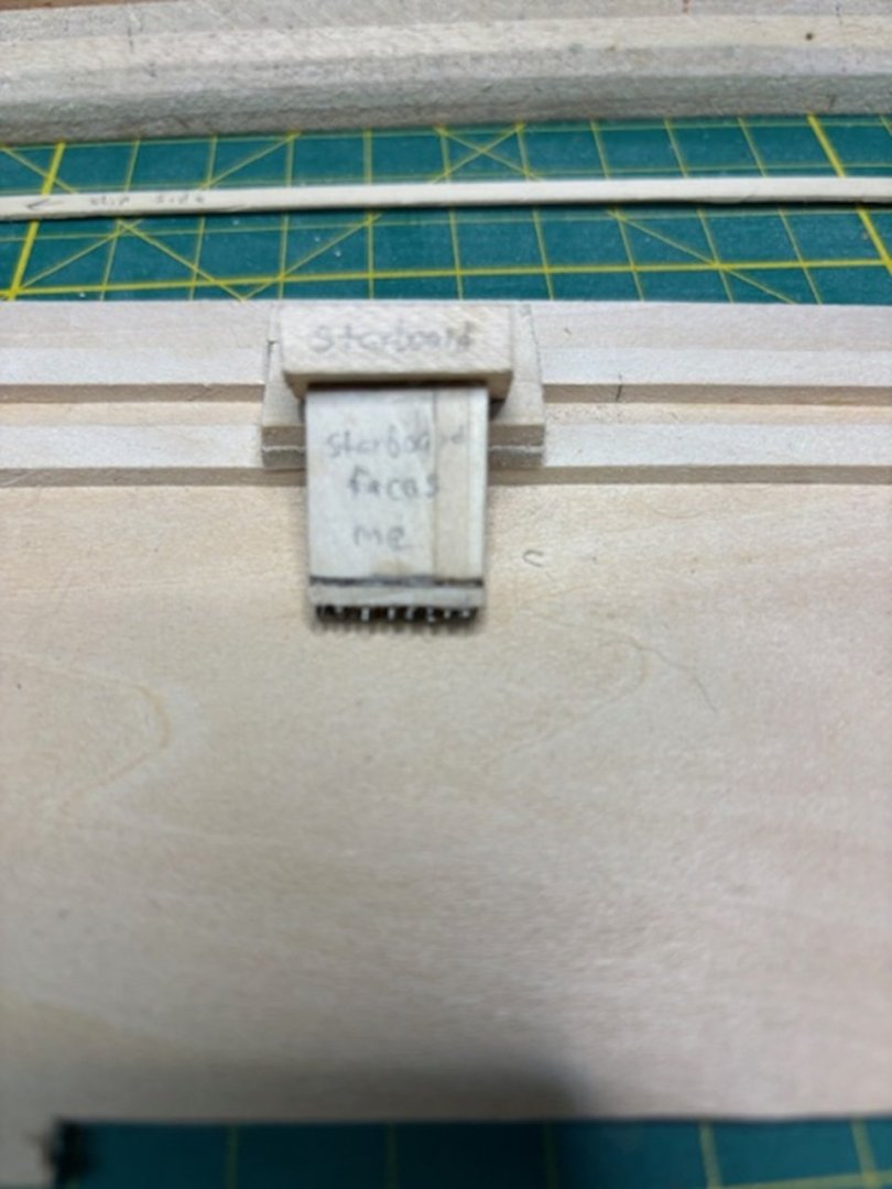
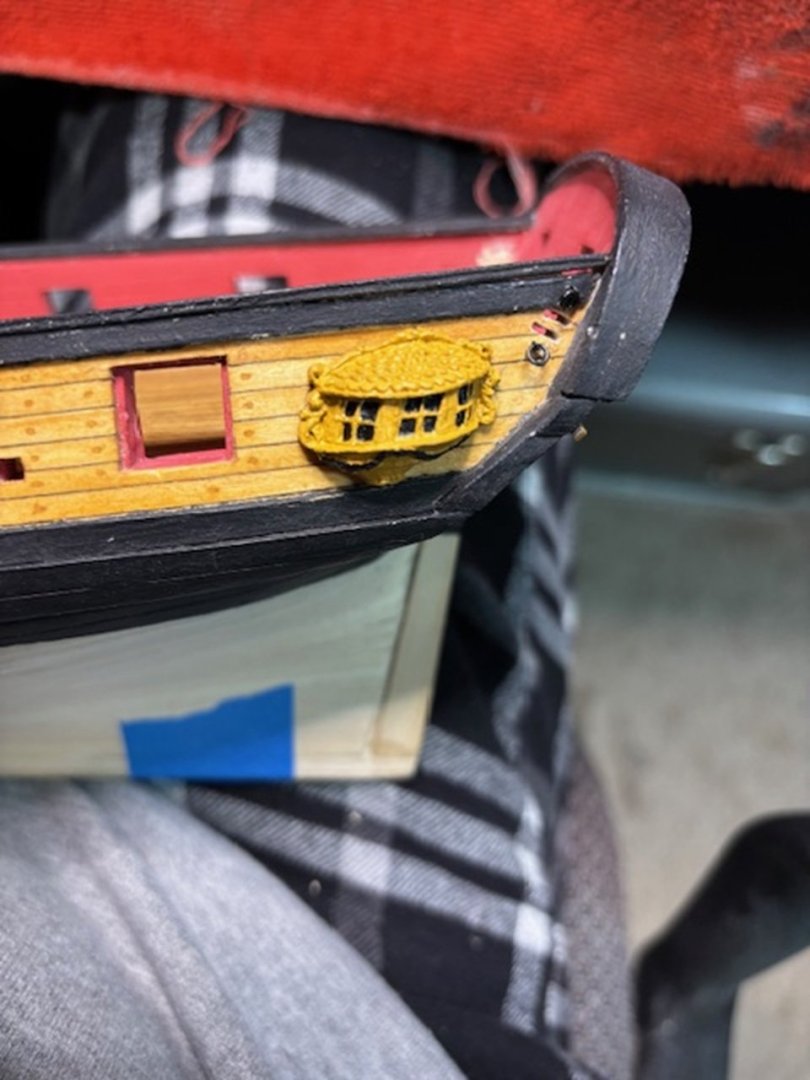
Been waiting for some nails to create the press for the copper plating. Nope, brass nails were too big. Had a thought. Looked behind my ship holder and saw the pins I use for my cosplay sewing. Yep, simple straight pins were the fix. I drilled appropriate holes in a thin piece of wood and inserted the pins. Then cut them down, used a 2-part epoxy to glue it to the jig as described in the instructions. Let that sit overnight and then used a drummel with a sanding piece to remove the sharp cut edges from when I used snips to cut the pins down. Once I was satisfied, I gave it a try. Not too bad if you look at the pics below. While I was waiting for the sanding sealer and brass nails to come in via the mail, I started work on the next chapter. Got the back stern work done and the sweep port hinges done as per my previous post of frustration. Not sure on the paint of that decorative stern piece. Incredibly bad molding I must say. I may end up repainting it. Also not happy with the metal mold of those two side stern pieces.


-
Glad to hear I can motivate. Still moving forward, but slowly right now. Having issues with the sweep port door hinges. The laser cut brass fittings are too big for my doors, so I'm having to find a work around. I checked the laser cut pieces on the ship plan print outs, and they are even too big according to the prints. The more I work on this ship, the more I'm having to create my own fixes. Give me my Niagara build any day. This is a beautiful build but most frustrating of the 4 I've built. More scratch built than I planned on.
-
Argaen Lok changed their profile photo
-
Thanks guys, I really appreciate the kind words. I do a lot of looking at other builds for instruction and inspiration. Has really helped clarify some items, inspired me to try a few new things and gave me plenty of building ideas. Thanks Salty. Unfortunately, not all of them do a good job of describing issues they had during the building process. I did do a pseudo build of one of the cannons. Turns out that I can put the swivel bracket flat on the deck, which also lines up with the bottom of the cannon port sill. Which is how it is supposed to line up according to the directions. I can live with that. I did that when I built my Niagara. Then the rest of the carronade lines up within the gun port just fine. I did go and put down a smaller 1/32 x1/32 waterway. I glued it in place but did not put glue under the carronade port sills. I figure I will cut out the small portion of the waterway where the swivel bracket pieces glues to the deck to line up with the port sill. It won't be historically accurate like I'd like, but I can settle with a happy medium. See the pick below. Plus, I didn't have to steam the waterway wood to fit into the bow curve. A win for sure. See the pic below.
-
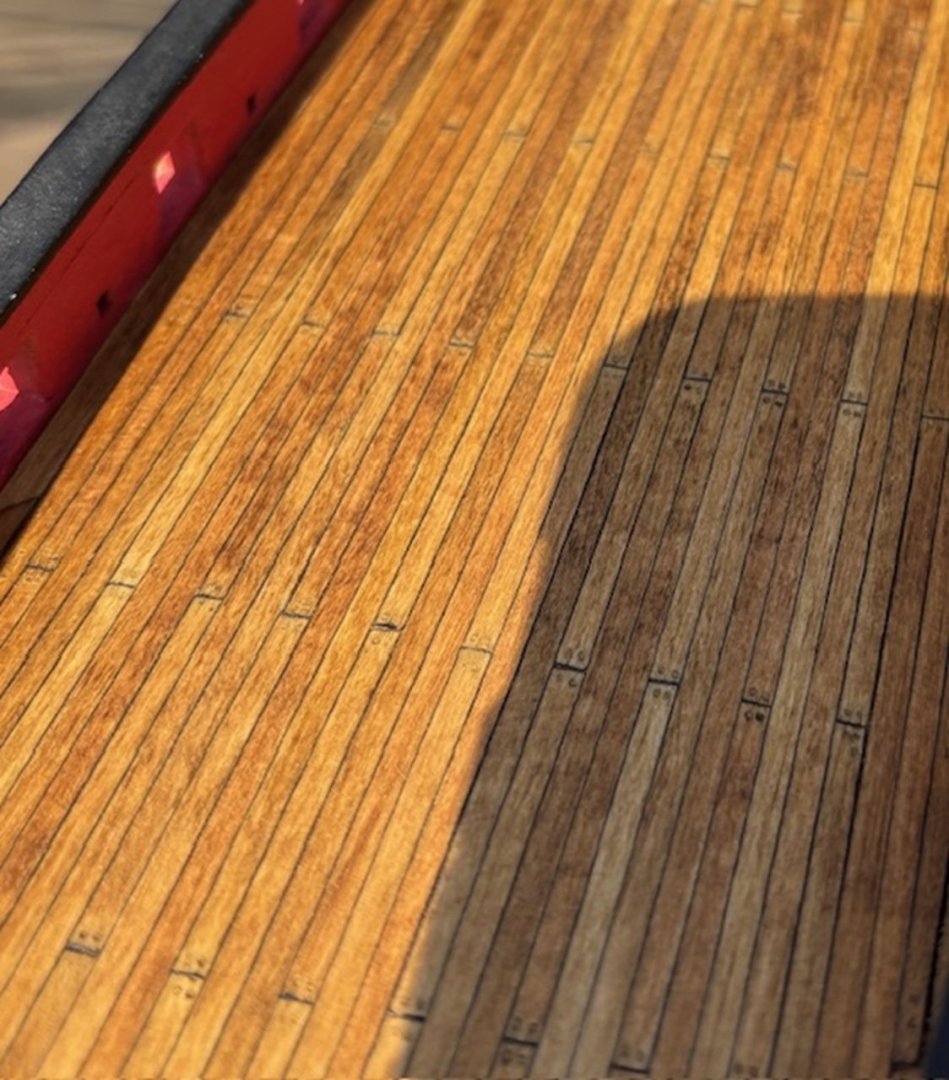
I continue to move forward. Put on two coats of Minwax Golden oak stain. Letting the first coat dry for 10 minutes before wiping off with paper towel. I let that dry overnight and then put on a second coat like the first coat. Next is the water line piece. Reading the instructions, I must have really messed up the gun ports because they are nowhere the height off the deck like the instructions say they should be. Instructions say there should be 1/8 of an inch but, not on my model. Most of my gun ports are 1/16 to 3/32 above the deck. So. I'm going to have to use a smaller plank of wood for the water plank. Thankfully I have smaller wood to do that but I'm really getting worried about my modeling skills. I could have sworn, with my hand on a bible, that all of my ports were exactly as they were supposed to be. When I put on all of the wood for the gun ports and sweep ports, they all matched up just like the instructions said. Even the planks on the outboard gunwale matched the lines of the drawings. Well, can't put the toothpaste back in the tube. Hopefully the cannons will line up inside the port appropriately. If not, I'm not sure how I'll fix that one. Maybe I'll put one cannon loosely together and see how it fits. Maybe I'll get lucky. Wish me luck. Hopefully anyone following this build will learn from my mistakes. I'm really not happy at the moment.

-
Thanks, it was the third time I've done those. Not sure how to describe what I did but I'll try. The first plank I used the plans and copied it. The ones after that I would first put a light pencil mark on the margin plank, towards the gunwale where the last plank comes off of the margin plank. Next, I put a mark in the middle of the next plant, at about the middle point. Because one does not want to cut the planks less than half the width. But don't cut it yet. Then I would lay the front of that next plank on the line with that mark on the margin plank. Keeping it in place and note where the margin plank comes out from under the plank you laid on it. Make a pencil mark on the plank where that margin plank comes out. Then you can remove the plank with its two pencil marks. It's short enough that you can use an exacto knife to cut a straight line between those two pencil marks. Then lightly take a nail file to that cut edge just enough to make sure the cut was straight down and not at an angle. Try not to file down the cut edge too much as you want to make sure you aren't going past the plank half-way point. Lay the cut plank back down on the margin plank where you put the first pencil mark on the margin plank. Then use a pencil to trace the outline of that cut plank. Remove said plank and use your exacto knife to cut on the inside of that pencil mark. Cutting it a bit small is okay. Then try to lay your cut plank into the now opened spot on the margin plank. How does it line up? Hopefully the space is a bit small. If small, I'd use a jewelers file, one with a fine point, to start filing the cut margin plank a little larger, frequently checking to see how your plank fits in it. Don't forget to put your caulk mark on the side(s) of the plank to show where tar-soaked ropes would fit between the planks. Once it fits, bang, glue down the plank to the bulk heads. Make sure to push that plank into that cut space in the margin plank. Then repeat for each subsequent plank. Hope that helps.
-
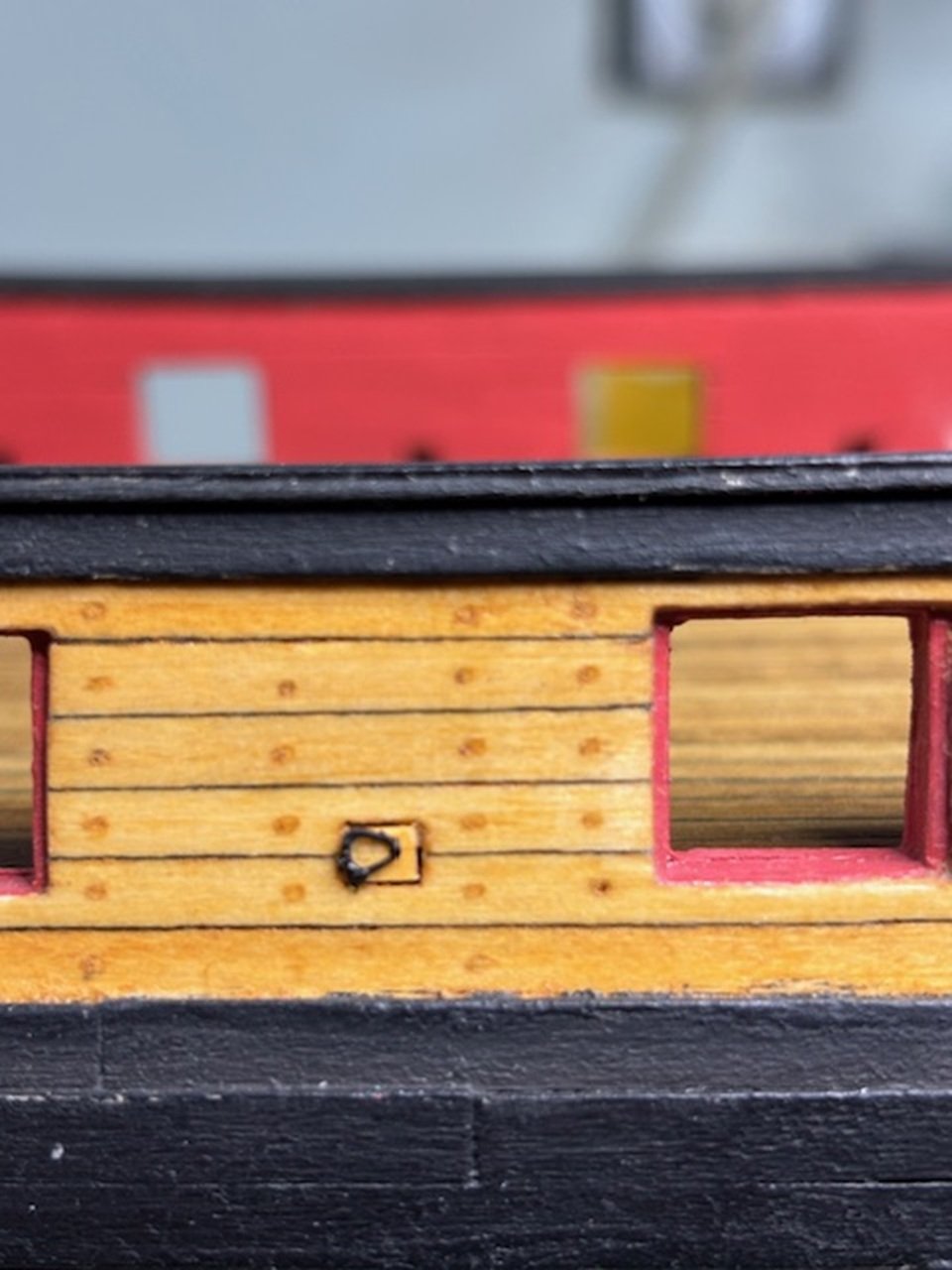
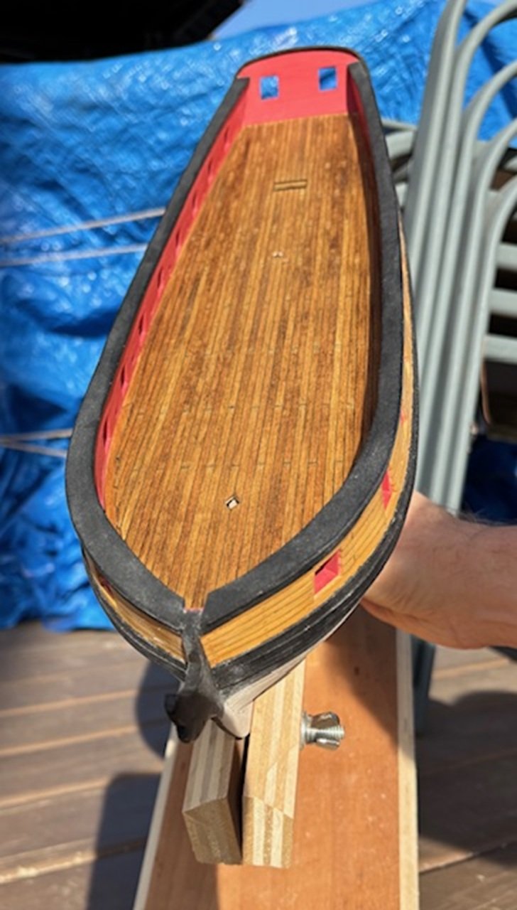
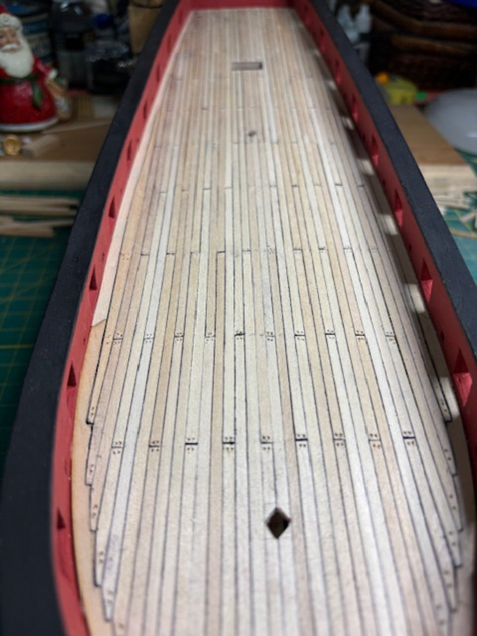
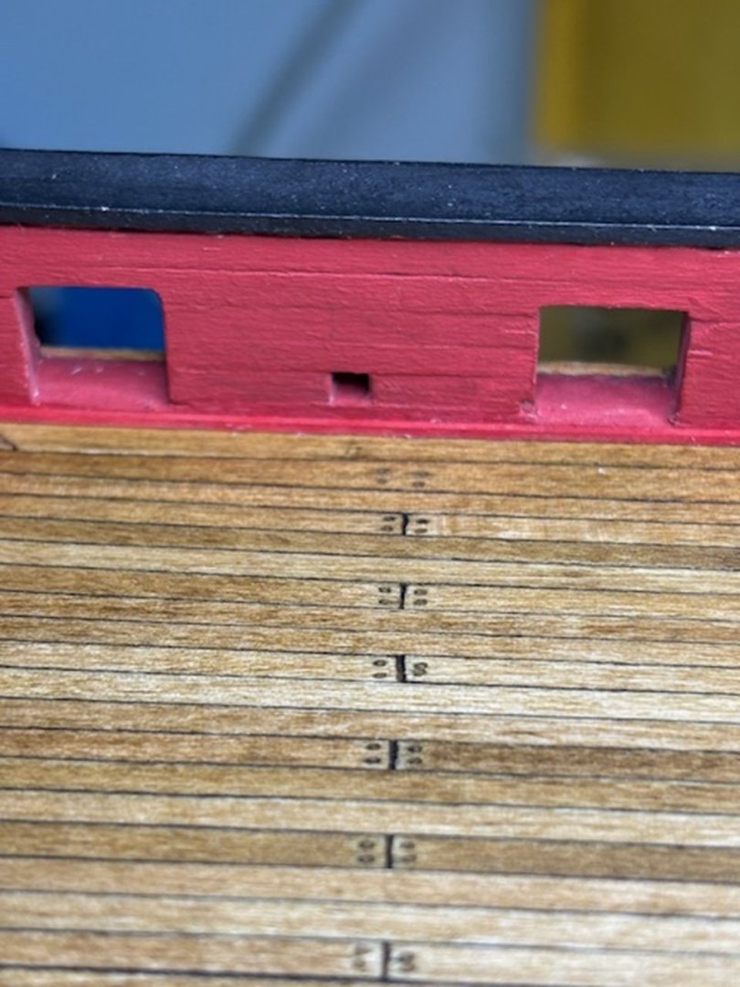
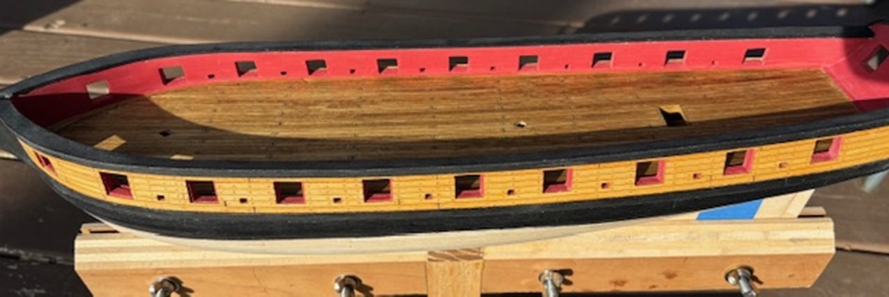
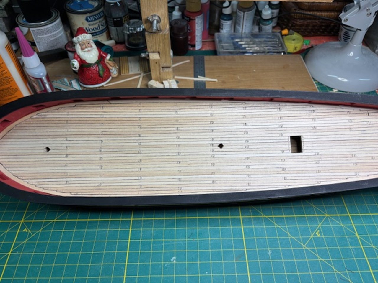
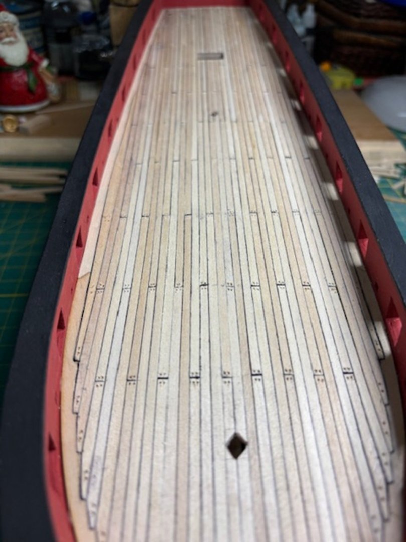
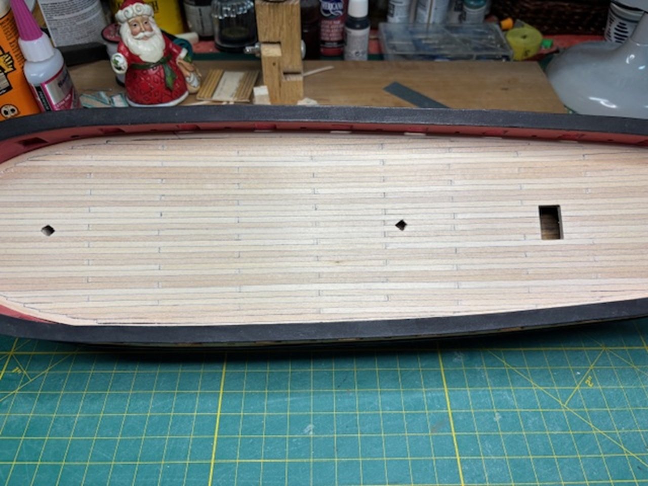
On to Chapter 7, the deck. I figured out a corrective action for the deck nose issue as I stated earlier. Next it was time to move on to putting the deck planks on. Yes, I did do the nibbing but not on the 6th plank back. I even counted the drawings, and the nibbing doesn't even start until plank 8. So, the instructions don't even match the drawings. But, whatever. The main point with the nubbing is to start it when the plants start having sharp edges. Which I did. I even nubbed the plants at the stern of the deck. Kind of made sense when one considers there would be pointy edges back there too. The pics below are the unsanded and wood nail holes drilled. The next pic is with the wood nails filled and the deck sanded. Not a difficult step as long as you are very careful to set the very first plank properly down one side of the center mark. That is very crucial. Mess this center plank up and they all will follow. You will also notice that I did the, every 4 planks cutting process. You will see that in the pics. The little diamond cuts are my markings of where my mast cradles are located and the large hole of course is the small section where the lower deck is located.
-
Thanks for sharing and nice work. My skills pale to yours.
-
I think I found a solution. I put a filler piece of wood at the head of that space. I did a little reading ahead in the instructions and found that the water way will have to be put in once the deck is done. So, I sacrificed a few inches if 1/16 x 1/16 wood that the water way will be made out of and placed it up front. Most of that space will be covered up by the water way. With that one filler piece up front, I think I'll fill in the rest with wood putty and then once the water way is put in, if the putty stains differently, it will hardly be seen. Guess I figured this one out myself.
-
Thanks. I'm really trying to step up my skills on this kit.
-
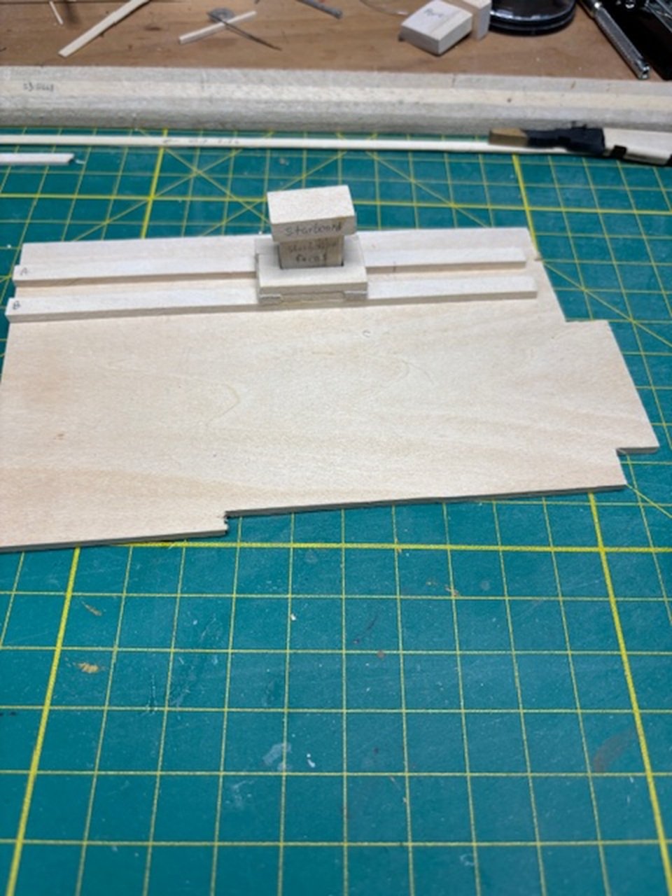
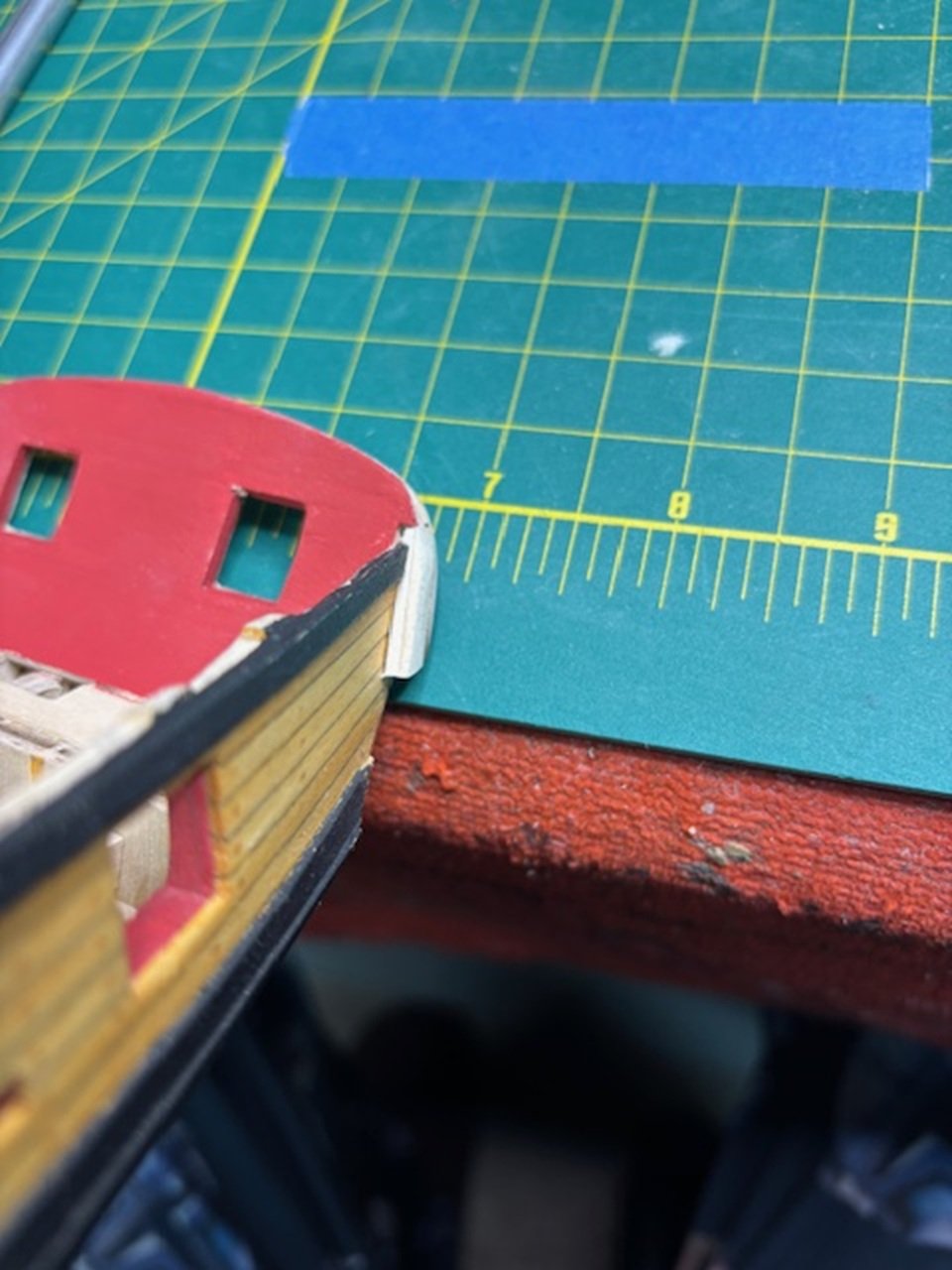
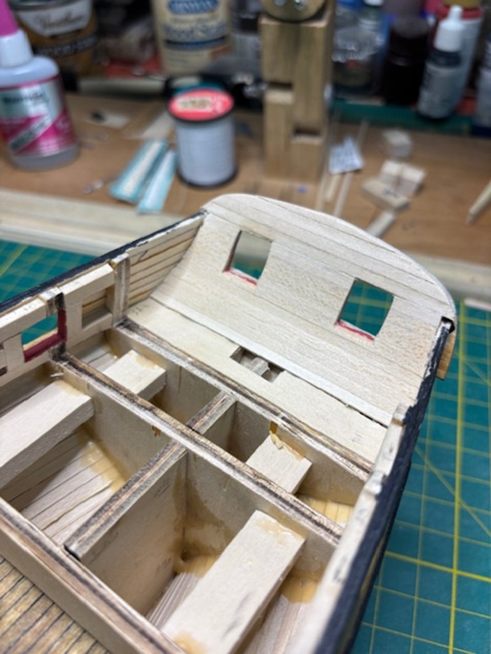
Finished the inside planking. The instructions say to cut the wood to the precise lengths to fit between the gun ports. IMHO, that lends itself to too much random messing up. I took a bit of a more time-consuming route and cut them a little longer and then used my jeweler files to then file down the insides of the gun ports to the appropriate dimensions of the already cut out cannon ports. That way there would be no guessing and no bad cutting of planks to make this work. See the pic below. I like my choice. Then I sanded down and painted the inside walls. Which you can see in the pics below. Moving along with rail caps. Like so many other things with my kit, even though I'm within acceptable tolerances, my cap rail is not the dimensions the instructions stated. Mine are a bit wider. Not much, but more than the 1/4" stated in the instructions as they should be. So, I did follow the instructions to a bit and placed a sheet of wood (not supplied), upside down and traced the outline of my upper walls. As seen the pic below. Then I measured the thickness of my walls with a compass (instead of calipers) and marked dashed lines a seen above. Yes, the bow does flare out. The instructions barely mention it, but let me tell you, it does exist. And measuring it accurately is a bear. And even though I did the measurements, I still cut the wood wider than needed. It's easier to sand down than to build up or redo. The other thing the instructions mention is that there is a bit of a lip on the inside and outside over the walls with the cap. Because it mentions to use an extra 1/16" piece of wood and glue it to the outside. And one can trim it to a decorative rail if one chooses. Unfortunately, the instructions did not say how much the overhang is. I sanded the cap rail down to 1/32" over each side. You can see how I held the cap rail in place below. If you look closely, you will see under the cap rail that I placed a 1/32" thick piece of wood under the cap rail so I knew how much to sand down to. I first did that on the inside, as it's way more difficult to sand inside the walls. For the most part, I really just sanded the inside cap smooth and then pushed it outboard so that the rail was 1/32" inside. Then I used the clothes pins and then I sanded down the outside remaining cap. As I moved down the rail, I would remove one or two clothes pins, sand down, replace the clothes pins and repeat. That little 1/32" piece of scrap also kept me from sanding off the stain. Once I got those done, I painted and glued into place. Pics of that are below. And yes, I left a bit of a gap for the bow sprit. Once the cap rail was done, it was time to move on to the deck planking. The instructions have you use the two laser cut boards. So, I got those out, sanded off the burnt wood and laid them inside the ship. Oh snap. The instructions state that everyone's bows will be a little different. Yeah, okay, I get that. I didn't think my bow would be off this much. See that big gap at the bow! Yeah. What I find odd is that I didn't really form the bow. That formation is from the pre-cut wood from the framing and false ribs. So, either I really messed up somewhere in my build, or the laser cut pieces are less accurate than they should be. Now I have, really, only two good options and a third not so pleasant option to correct/ fill this gap in. Option 1, and the easiest, is simply fill in the gap with wood putty and sand smooth. There is a chance that the wood putty will stain differently than the rest of the wood for the deck..... but, there is going to be a bow sprit, and two rails of pins up there over the top of said space. So, there is a very good chance, if it stains differently, no one will really see it. Option 2, cut out two well shaped pieces of scrap wood to fill in that gap and glue them into place. A little more difficult and the angles up there are more along the lines of French curves. Not easy. but at least the stain will be the same. Option 3, and one I really don't want to deal with, is to cut back a bit of those two deck pieces and then cut two new pieces that properly fit. Thus, trying to match up the proper width of the remaining deck bow pieces while matching the shape of my bow. YUCK! So, I need all of your opinions, those of you who have passed this step already. Which option is more prudent? Please help!


-
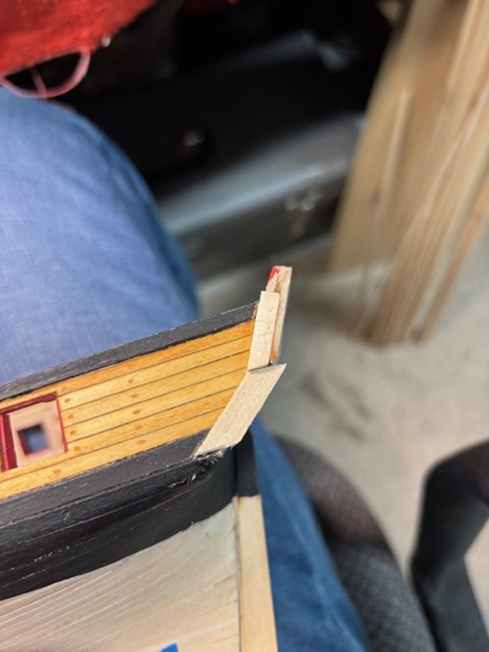
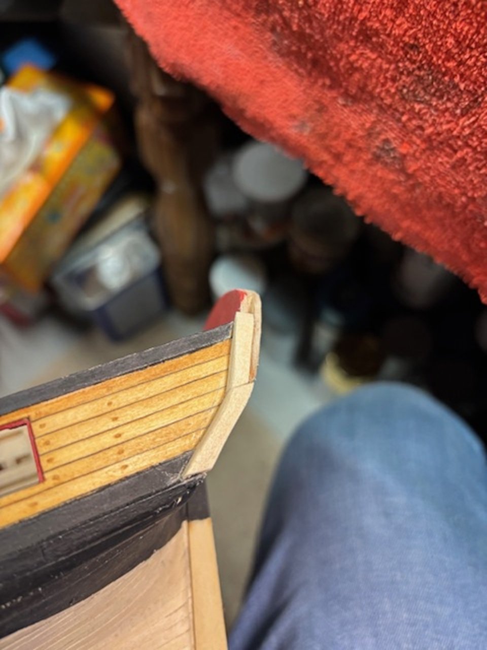
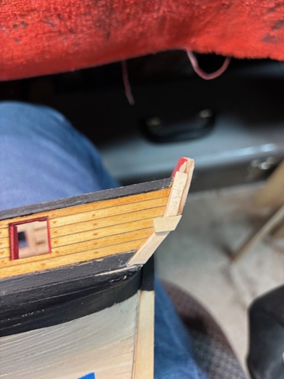
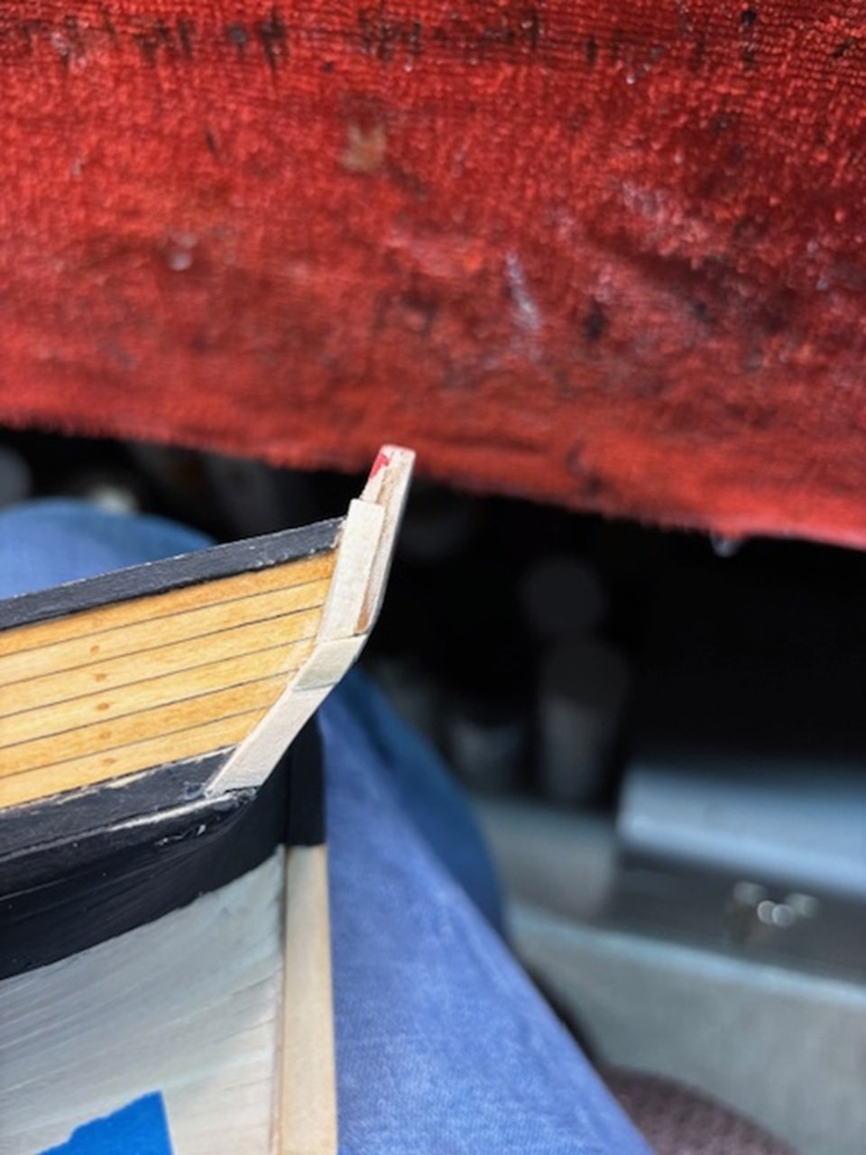
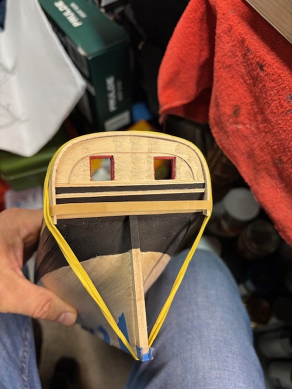
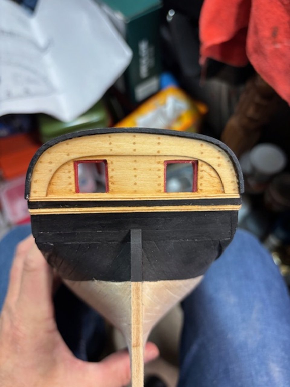
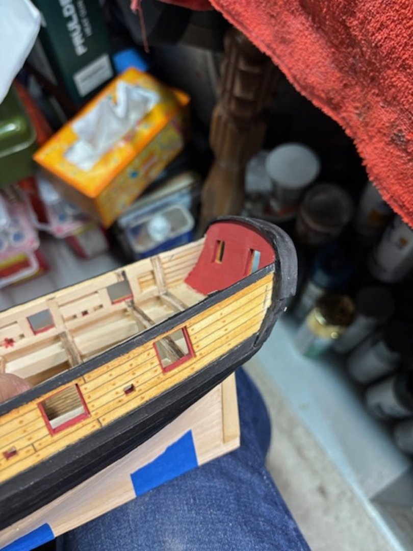
Okay, short chapter 6 is done. I read the directions and was having a difficult time understanding the instructions. I knew what the intent was by looking at the pics in the manual and the drawings, but I just couldn't picture what the author was trying to convey. So, I ventured a bit on my own, fully understanding the intent of the final work. I warn you; this one is a bit pic heavy as I describe what I did. The results are 95% the same, I just took a different path. That's one nice thing about building wood models; there is always a little wiggle room to venture on your own yet achieve the same results. I will also add that I am very pleased that I always keep the leftover strips of wood from my previous builds. One never knows what will be needed down the road. For some reason, this kit seems a little short on wood. Or perhaps it's just me. but this work is all done with scraps. I started out by gluing together two 5/32 x 1/16 scrap pieces of wood so it would line up with the side of the transom. I then added two glued pieces of 1/4 x 1/16 under the first piece. Realizing that the design more or less wants you to step down from the full width of the transom to the side of the ship. Then I sanded those down. Then I added a 3/16 x 1/16 piece in the middle so the cap would come over the top and sit on top of this piece. This way the cap would have the step down to the side of the hull. And then sanded that down so it curved down and ran smoothly into the bottom piece. Next was the cap work. I must say, I was a bit disappointed that this piece of wood did not come with the kit. Luckly for me, I had left overs from other builds and had what was needed. This cap piece is the same thickness as the instructions call out. So, I cut out the wood and soaked it in hot water. I used a triangle shaped file to add creases to the underside of the cap so I could start the bending process. Much like a described previously when bending the planking under and up the stern. Once I got the creases in, I used a large rubber band and wrapped it around the first step of bending the cap. Sorry, no pics of that, but the cap was NOT fully bent at this stage. I let that soak in the hot water for 5 minutes and then added a smaller rubber band and let it soak in the now warm water for 5 minutes. I did NOT cut the cap in half like the instructions said. I wanted to try and make it one piece. if it snapped, I had enough scrap left over to start again and then cut it in half. Luckily, I was successful. Then I laid the cap over the transom and rubber banded it down overnight. Note how I made the cap longer than it needed to be. This would allow me to cut the cap down to fit over and rest/shelf on that middle side piece I described earlier. And my results. Like I said above, this was my own journey, but I wanted to explain it here just in case anyone else seeing this, and was confused by the instructions, could have an alternative path to achieve the same results. Yes, I also added the wood nails to the stern since I figured it wasn't made out of a single large piece of wood. Nothing in the instructions like the sides, about that.


-
Argaen Lok reacted to a post in a topic:
US Brig Syren by Argaen Lok (aka Scott Larkins) - Model Shipways - Scale 1:64
-
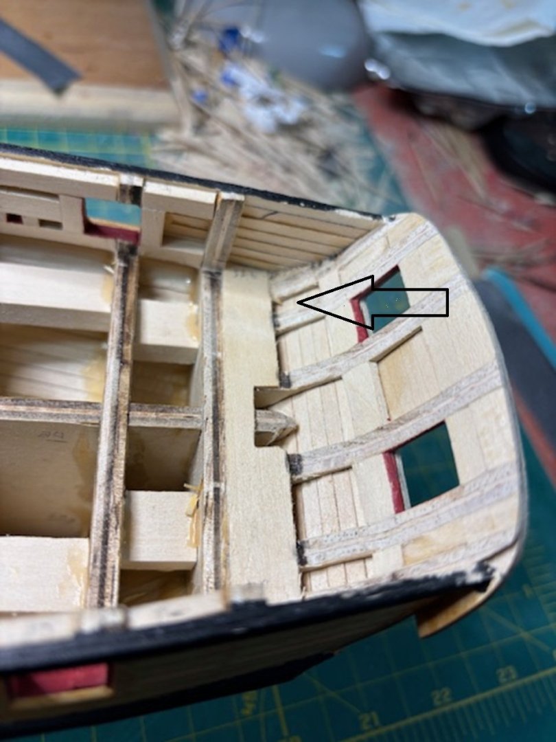
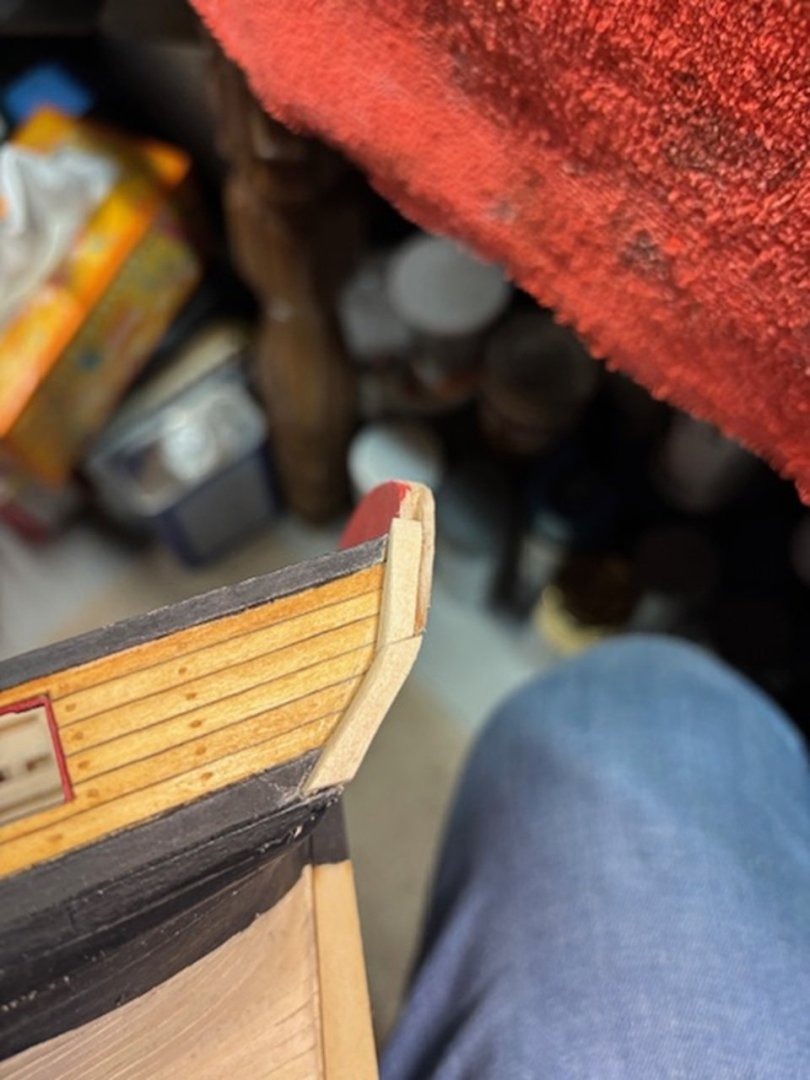
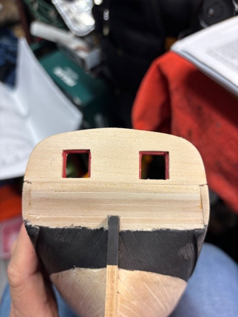
Started chapter 6, the stern work. I did cut the planks to fit right to the sides of the gun Wales. I know that you won't see that little bit once the inside Wales are done, but I'll know if I didn't fit it all the way. Luckily, the planking fit perfectly under, around and over the top of the gun ports; no notching needed. Did a little sanding, shaping and then painted. Not too tough. The hard stuff is next. I put the arrow in here because I wanted to call out the most difficult parts of sanding the stern down to the required 1/8 -3/32 thickness. I went with the1/8 thickness because 3/32 just seemed too thin. But the caution here is trying to shape the angled bottom of the stern posts, under the cannon ports, to all be the same size. Yeah, it's easy to sand down the large back stern face, but sanding down to stern posts at they angle back is tough. Maybe it's because I messed up the sanding and created a valley in those posts. So, I used a straight edge exacto knife, kind of looked like a chisel, and hand sanded the parts. The other difficult part was sanding the newly added planking right there in in the corner near the gun Wales. Hand sanded those too. And when I say hand sand, I mean squeezing my finger into the corner with sandpaper. But I got it all sanded to be smooth and equal. I'm sure I must have messed up those angled stern posts when I accidently sanded in a valley. So, A WORD OF CAUTION DOWN THERE. Guess we'll see just how bad I messed up once I cut the hole for the rudder. Fingers crossed.