rturcic72
-
Posts
40 -
Joined
-
Last visited
Recent Profile Visitors


-
 It's been a while since I gave an update...I'm still here...Anyway, I've been moving slowly still rigging the carronades. I've had to concentrate on getting a new government contract since the one I was on had ended and the customer had changed the rules for business size.. so, I've been doing my side gig to make up for any temporary losses in net income until I pick up another contract. It usually takes about 2-3 months, especially around the start of the new Fiscal Year.
 -
 ccoyle reacted to a post in a topic:
USS Constitution by rturcic72 - Model Shipways - 1/76
ccoyle reacted to a post in a topic:
USS Constitution by rturcic72 - Model Shipways - 1/76
-
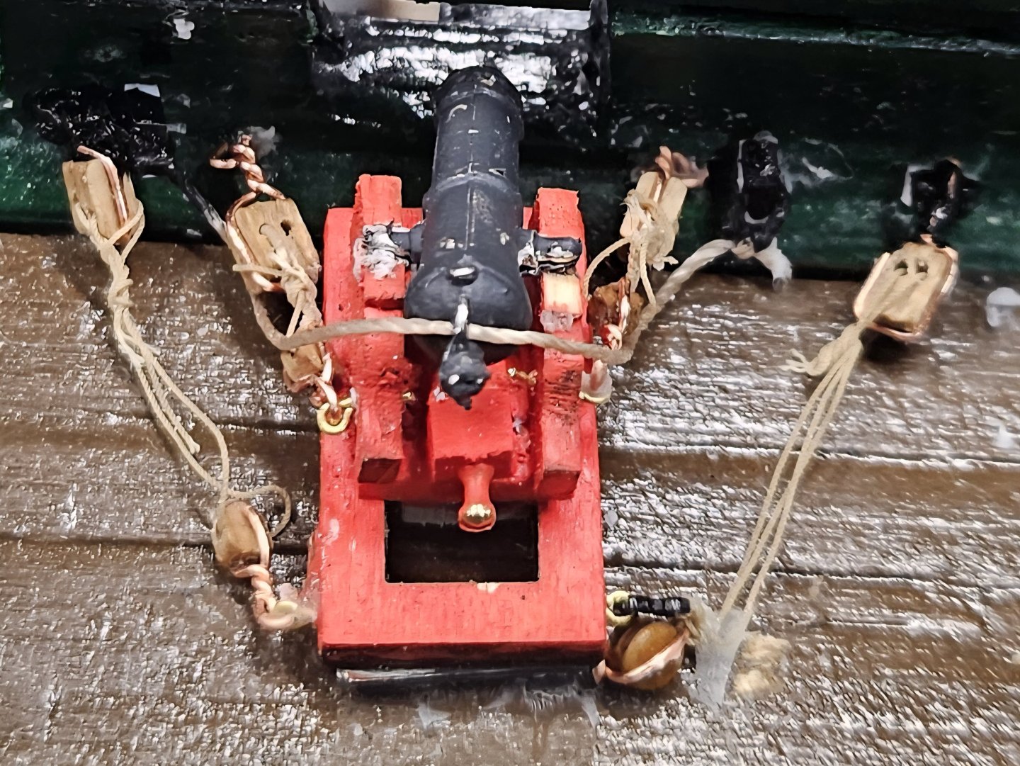
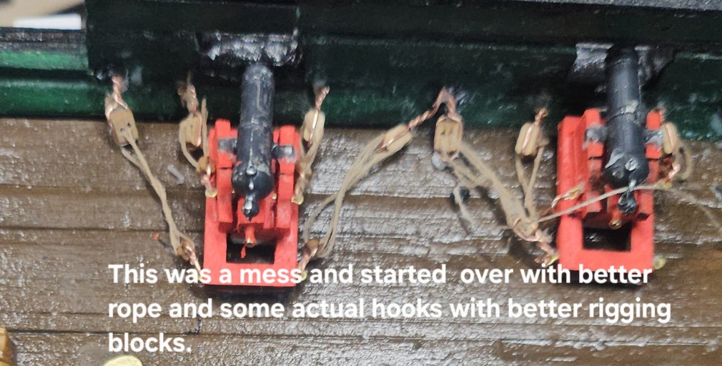
I haven't forgotten to keep up with the build. Rigging the carronades is definitely time consuming because of the how small things are to work with.Having new thread come in, makes thinks much more manageable to work with and looks much better than the previous photos. Also, my normal day job is a Government Contractor and I just finished one contract and working on getting onto another. Being a single father, I dont have yhe luxury of relocating, but I've made it through these storms before, but it takes up time sending resumes and doing interviews since the new Fiscal Year brings in new contracts.
-
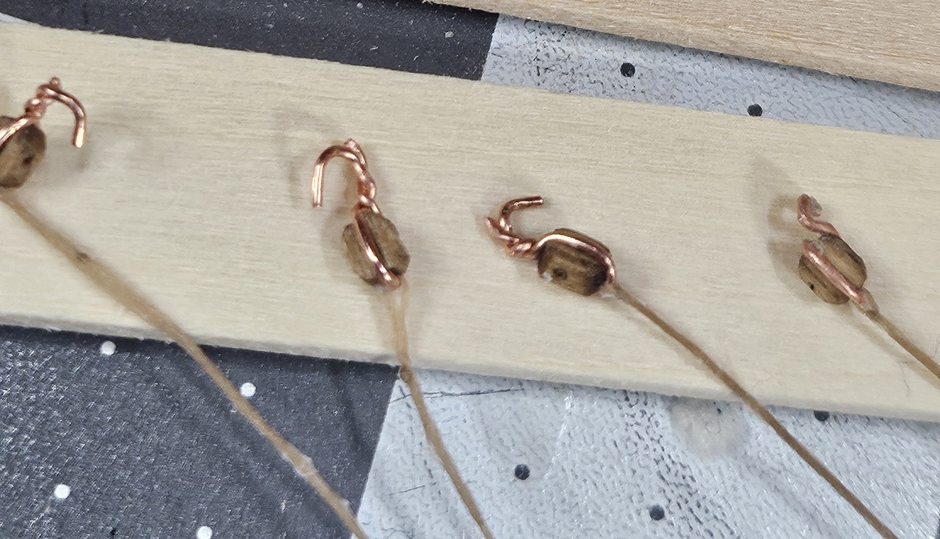
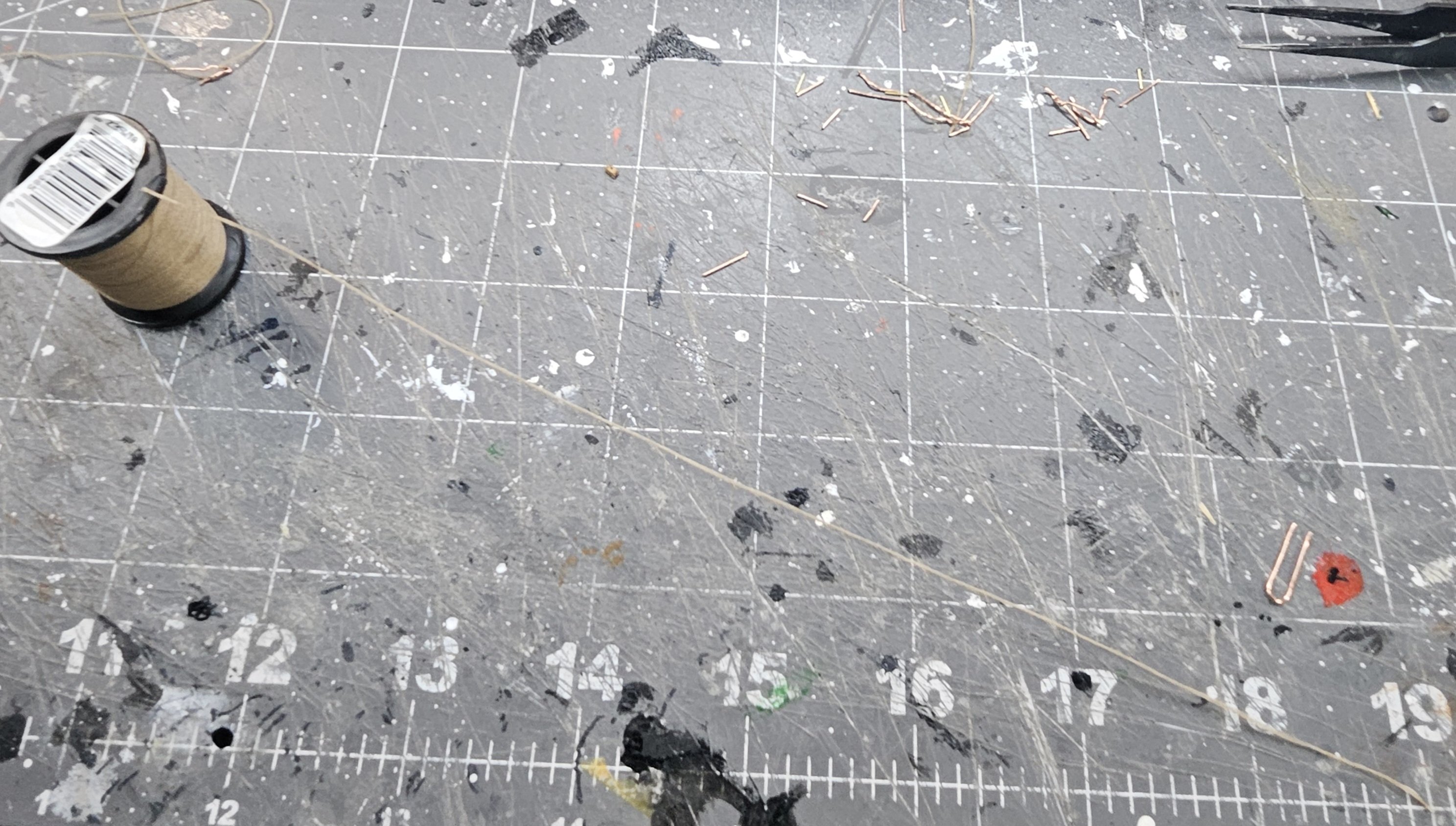
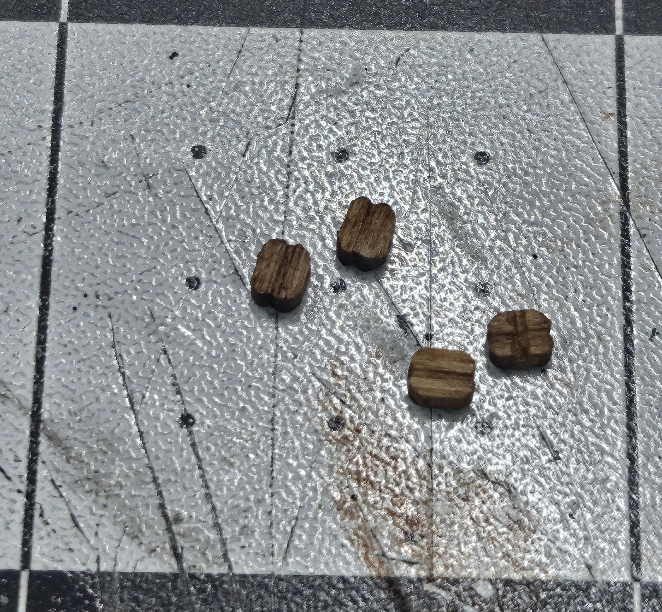
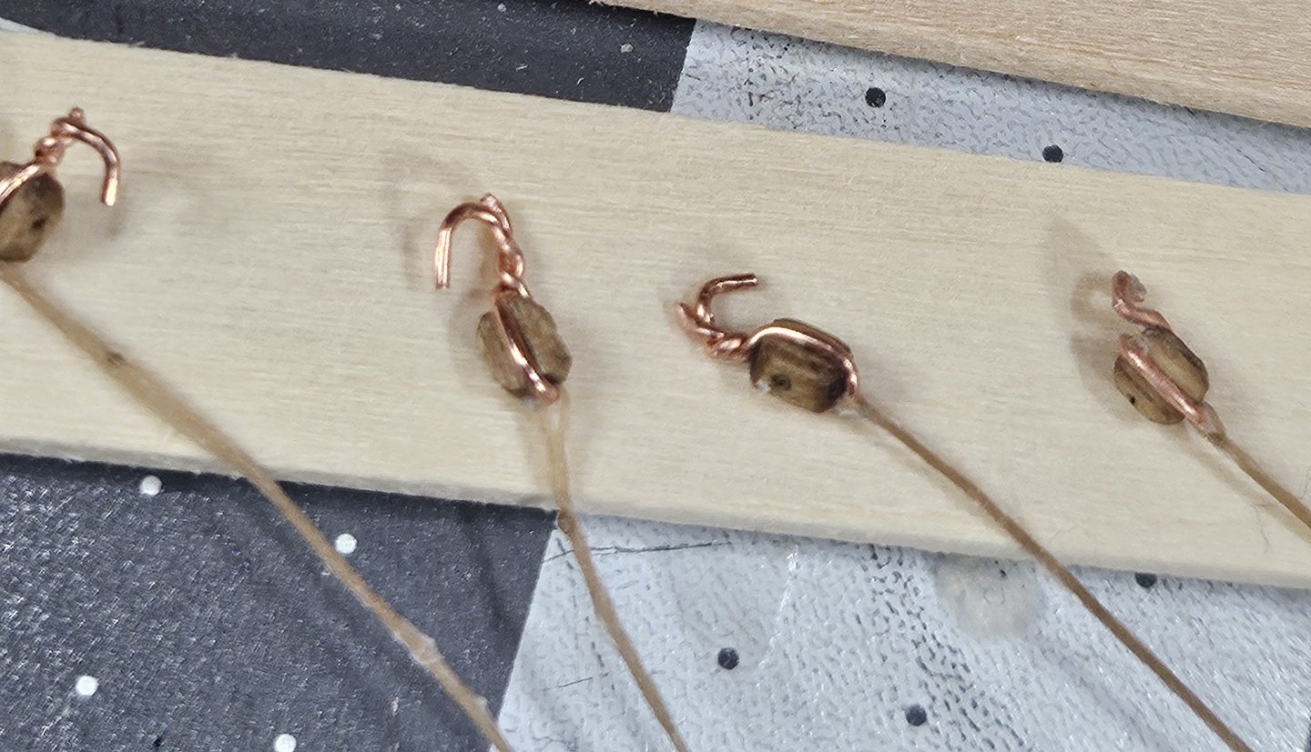
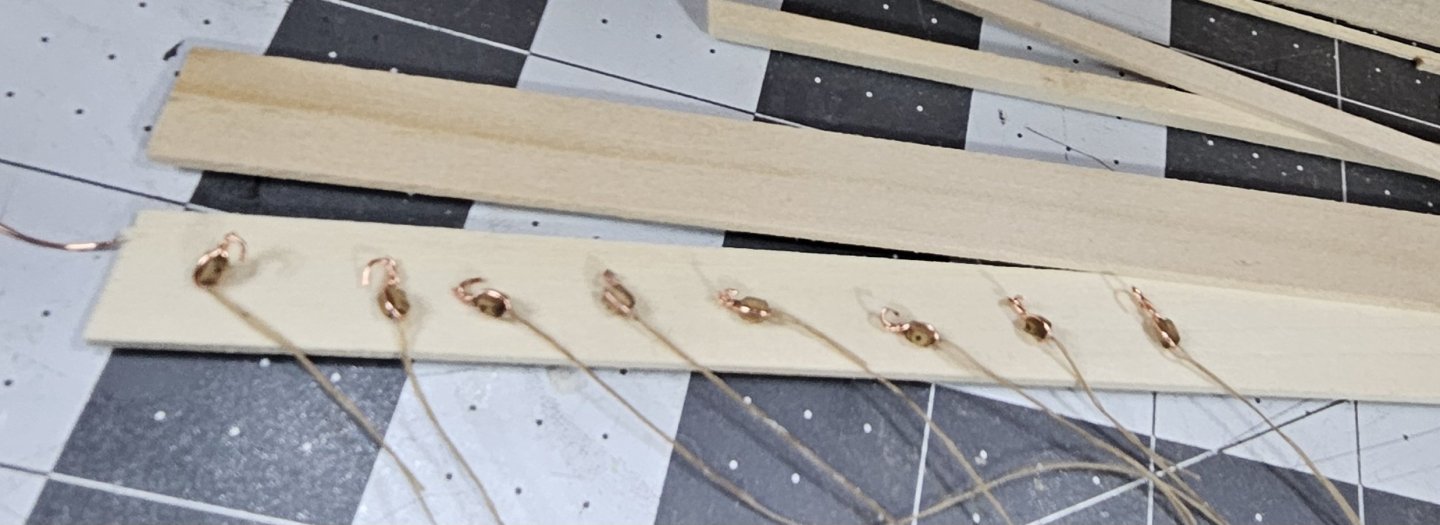
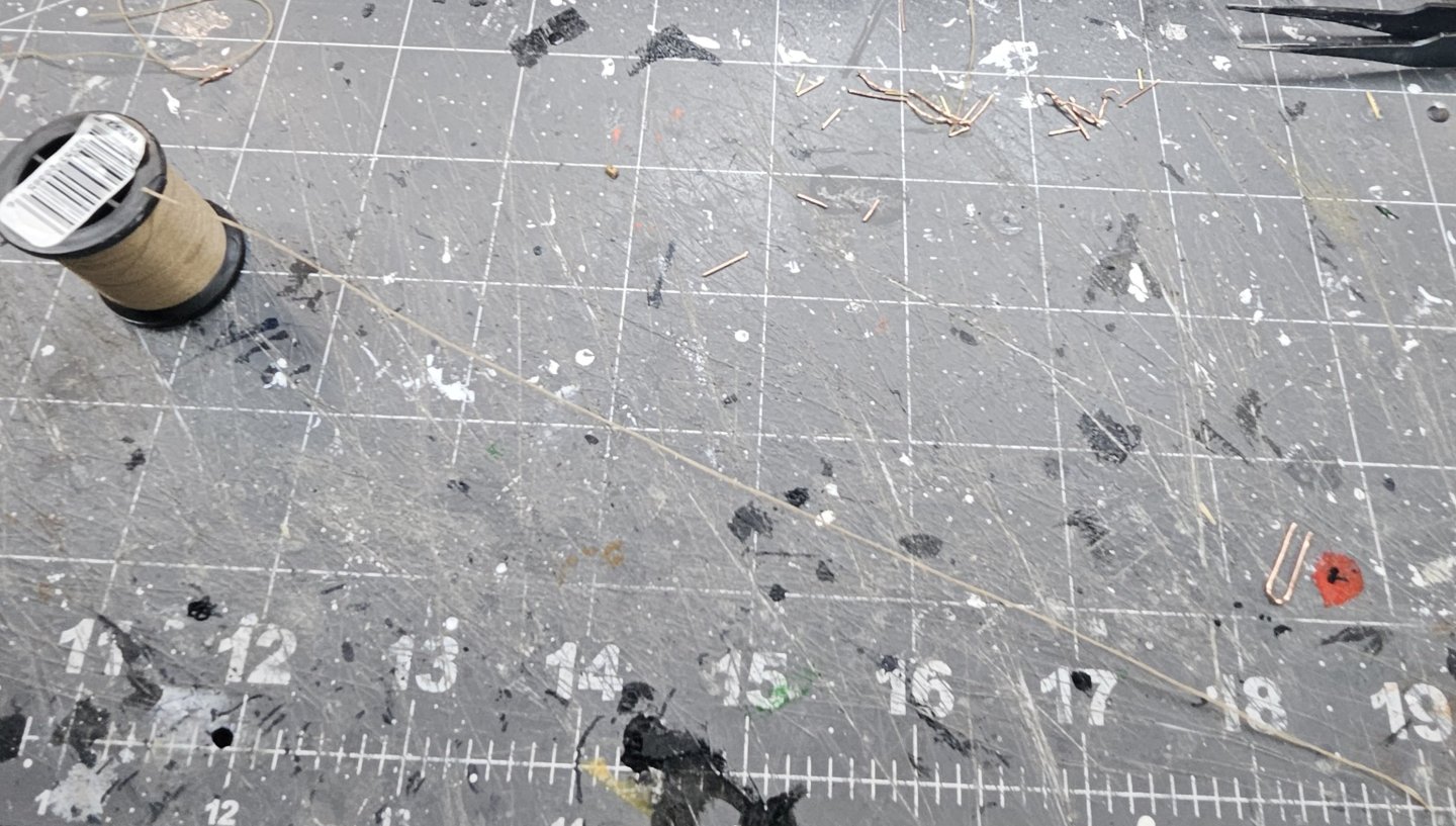
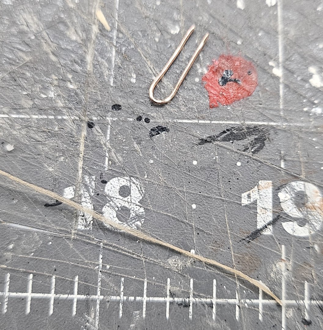
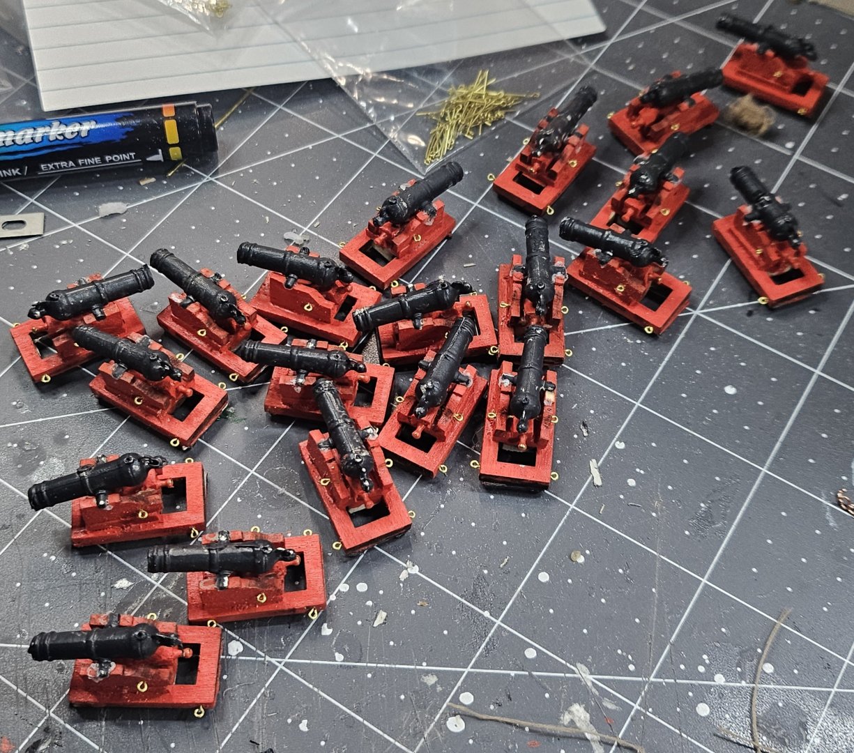
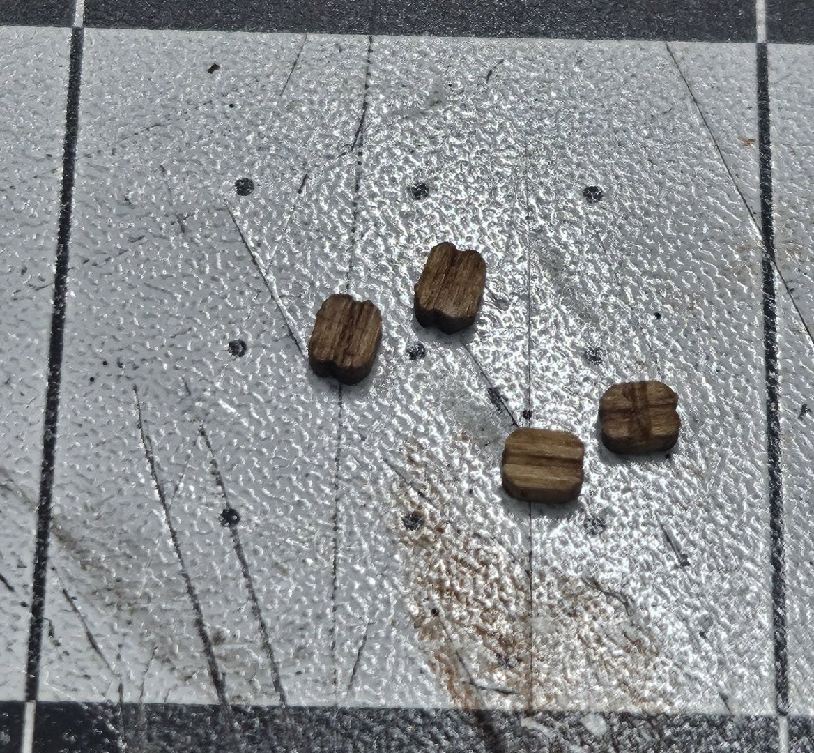
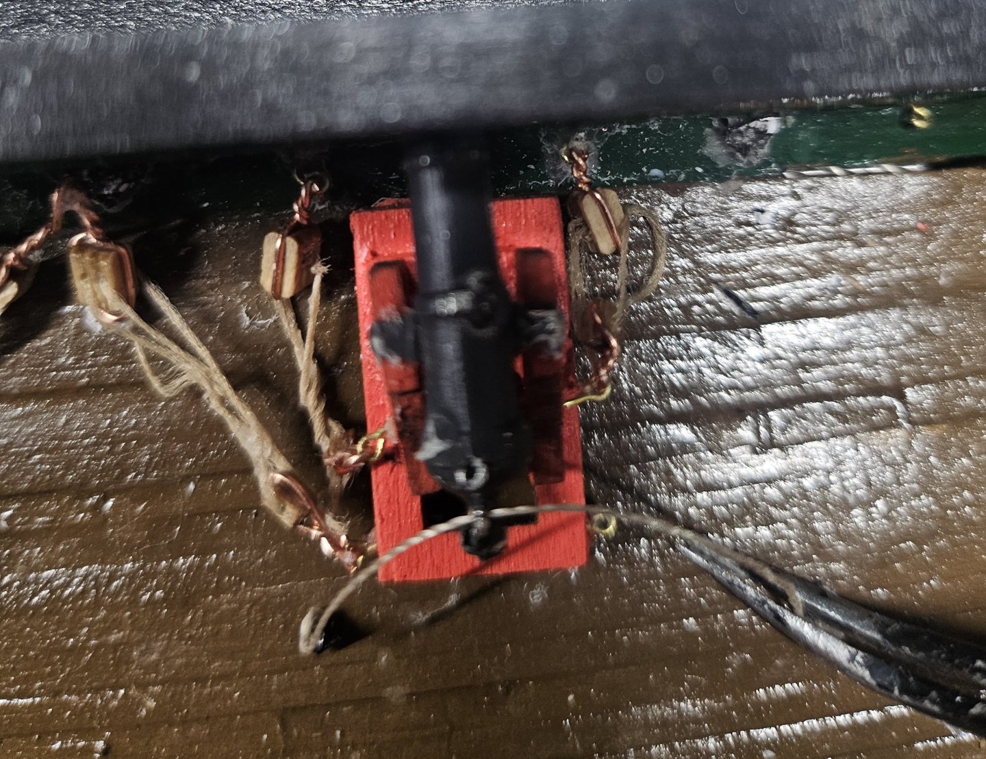
This is just a quick update that is being broken up in chunks because it involves manufacturing several wooden parts that are time consuming which is really an understatement, lol. I would have thought that the ship's wheel and capstan and initial deck work would have been the most challenging but turns out that those turned out pretty well. But I spoke too soon and then found out the hard way that the carronades and rigging, more so the rigging to me is more of a nightmare than I expected, not that it is hard to do, but because of the tiny scale you have to work with along with inadequate size/type of tan thread given in the kit, so I've had to improvise building the 80 to 160 blocks with hooks and seized rope. So, here is what I've had to deal with and I'm almost sure I'm not the only one to have any of the similar issues to solve. So, I built the carronades and put them in the "Cannon Coral." Altogether you have 20 carronades each one is made up of 15 parts. this took several days to make because of the need to paint them and work with parts that require the assistance of fleas to help, These blocks are the smallest in the kit and the most painful to deal with. I put four of these at 3/32 inside of a 1-inch square on my mat. Yes, these are very tiny and required a hook and thread be added. The 1/8 double block is easier to work with and small but only required the hook. In the practicum, Bob mentioned that he originally started with hooks and blocks he ordered from a hobby shop and then realized there wasn't enough to cover half of the carronades, so he switched over to the materials provided in the kit. This required building a hook by wrapping what I think is 36-gauge silver wire around the side with the groove and bending the end for the hook. He does not use the thread in the kit because it was inadequate in size and not made out of nylon. He uses his own line or thread from other ships he has built, so of course when seizing a line, it's not bad because the thread will fall into place and not curl up backwards on you. Yes, he recommends buying a specific wire and thread, but I improvised here because I have wire close enough to the gauge used and ended up using the thread in the kit that was not fun to work with because it truly is inadequate and frays very easily. It was difficult to control and nearly impossible to seize it properly without it fraying, trying to keep the lines in place held together by hand of a clip of some kind. The copper wire I had used before in the kit is what I used for the hooks and of course it can be painted black just like the silver ones. I had disintegrated several of the tiny, microscopic single block trying to get the copper wire and the thread onto it. Doing this 80 times is probably like solitary confinement in prison. So, to improvise the seizing, I would rub CA glue on both ends of the thread to minimize fraying on the ends and most of them were about 4 inches long to give enough slack to wrap around the double block to attach to the ship and the carronades for the rigging. I did this by cutting the copper wire into 1-inch pieces and then folding them in half creating a small semi-loop so I could get the tiny block inside with the groove on top and bottom to capture the copper wire. I would take one end of the thread and tie it around the copper wire with one knot to hold it in place with about an inch of slack to later on simulate a seized line. Whether you seize it or do it the way I did it, you can barely notice any difference because the seizing is primarily on the inside of the line. Once I tied on the thread, I would get my tweezers and move the tiny block right in between the copper loop and thread and squeeze hard to hold everything together and use the needle nose pliers to twist the wire on a couple turns, then trim and curl the tip which was roughly 1/16. I later started using forceps clamps like scissors then to hold everything because my fingertips started killing me because of the death grip I had to put onto the block, the thread, and the wire which turned out to make things a bit easier.one I trimmed the hook, I would spin the end with the hook and the thread several time and spread out about an inch and then use the CA glue and run it up and down that one inch piece and it would not only stay together, but also was flexible to do work like a real rope. The double thread twisted together gives the same appearance as though the thread was seized. Had we been given the correct thread in the kit, sure I would have seized it, but why waste time and money doing the same thing a different way...? It took me about a week to make the first 40 and I still have 40 more to go, plus 80 hooks on the double block, not to mention at least 40 eyebolts, 40 double holed fitting you have to cut from polystyrene, and another 20 polystyrene fitting, and all of this has to be attached to the ship before rigging all of the lines to the carronades. I can only imagine when I get to the actual masting and rigging of the ship, that that will be more traumatizing...this is just a taste, lol.
-
 mtbediz reacted to a post in a topic:
USS Constitution by mtbediz - 1:76
mtbediz reacted to a post in a topic:
USS Constitution by mtbediz - 1:76
-
scrubbyj427 reacted to a post in a topic:
USS Constitution by mtbediz - 1:76
-
 rturcic72 reacted to a post in a topic:
USS Constitution by mtbediz - 1:76
rturcic72 reacted to a post in a topic:
USS Constitution by mtbediz - 1:76
-
USS Constitution by mtbediz - 1:76
rturcic72 replied to mtbediz's topic in - Build logs for subjects built 1751 - 1800
Wow, you really have an incredible talent to being a true scratch builder. -
mtbediz reacted to a post in a topic:
USS Constitution by mtbediz - 1:76
-
rturcic72 reacted to a post in a topic:
USS Constitution by mtbediz - 1:76
-
USS Constitution by mtbediz - 1:76
rturcic72 replied to mtbediz's topic in - Build logs for subjects built 1751 - 1800
Mustafa, what size are your eyebolts? -
USS Constitution by mtbediz - 1:76
rturcic72 replied to mtbediz's topic in - Build logs for subjects built 1751 - 1800
Does anyone recommend a specific size for the hooks used with rigging the carronades. I Imagine a larger eyebolt size as well... -
woodartist reacted to a post in a topic:
USS Constitution by mtbediz - 1:76
-
rturcic72 reacted to a post in a topic:
USS Constitution by mtbediz - 1:76
-
USS Constitution by mtbediz - 1:76
rturcic72 replied to mtbediz's topic in - Build logs for subjects built 1751 - 1800
Gregg, thanks for the valuable advice. I definitely want better blocks and deadeyes, etc. I feel the quality needs to be there if you want the ship to look good. I also want hooks instead of making them from wire. They should have included the hooks in the kit. When you make them from wire, they tend to be larger or bulkier. Trying to figure out how much rope you need so there isn't too much slack is the hardest part for me. I had to install 2 eyebolts, 2 horizontal fittings with 2 drilled holes, and the 2 vertical fittings with one drilled hole for the breech and onto the planksheer. The pain with this is that there's not a enough space to work with and since 2/3s of the fittings are polystyrene, you have to make sure the CA glue secures it well, otherwise when you try to hook the rigging and it falls off, then you have to start over again and hopefully none of the holes are blocked with the CA glue. I understand Bob Hunt's quest to make this look like the real thing, but I think good eyebolts are a much better solution. For Mustafa, I would love to come and visit. Last time I was in Turkiye was 2009. I was part of the US Naval Exercise for Baltic Operations 2009 and Turkiye hosted our Guided Missile Destroyer that I was on at the time as a Senior Lieutenant. We pulled into Constantinople and going through the Turkish Straits it was the most beautiful place I've ever seen along with the Grand Mosques that are truly amazing. I was the Officer of the Deck and drove the ship through the straights. I've been around the world 6 times in my 30-year Navy career, and that is the number one country that sticks out that I want to visit again on my bucket list. So, when I think I'm ready, I will definitely drop a line to plan a trip. there is so much to see and do in what is considered a crossroads in the world because of the Ottoman Empire. My entire family emigrated to the US from Croatia. My last name is Turcic which is a derivative of King George Turcin during the Ottoman Empire, so there is some odd connection with my family origin and it's likely a very miniscule piece because I'm not from Turkiye. Anyway, I'm going to try t order some of the rope, and I also think some of the rope might be a bit too small, so I'm open to size recommendations that seem to work since it appears half of the rope in the kit is nt the correct size anyway accoring to the practicum. -
rturcic72 reacted to a post in a topic:
USS Constitution by mtbediz - 1:76
-
rturcic72 reacted to a post in a topic:
USS Constitution by mtbediz - 1:76
-
rturcic72 reacted to a post in a topic:
USS Constitution by mtbediz - 1:76
-
rturcic72 reacted to a post in a topic:
USS Constitution by mtbediz - 1:76
-
rturcic72 reacted to a post in a topic:
USS Constitution by mtbediz - 1:76
-
mtbediz reacted to a post in a topic:
USS Constitution by rturcic72 - Model Shipways - 1/76
-
mtbediz reacted to a post in a topic:
USS Constitution by rturcic72 - Model Shipways - 1/76
-
mtbediz reacted to a post in a topic:
USS Constitution by rturcic72 - Model Shipways - 1/76
-
mtbediz reacted to a post in a topic:
USS Constitution by mtbediz - 1:76
-
USS Constitution by mtbediz - 1:76
rturcic72 replied to mtbediz's topic in - Build logs for subjects built 1751 - 1800
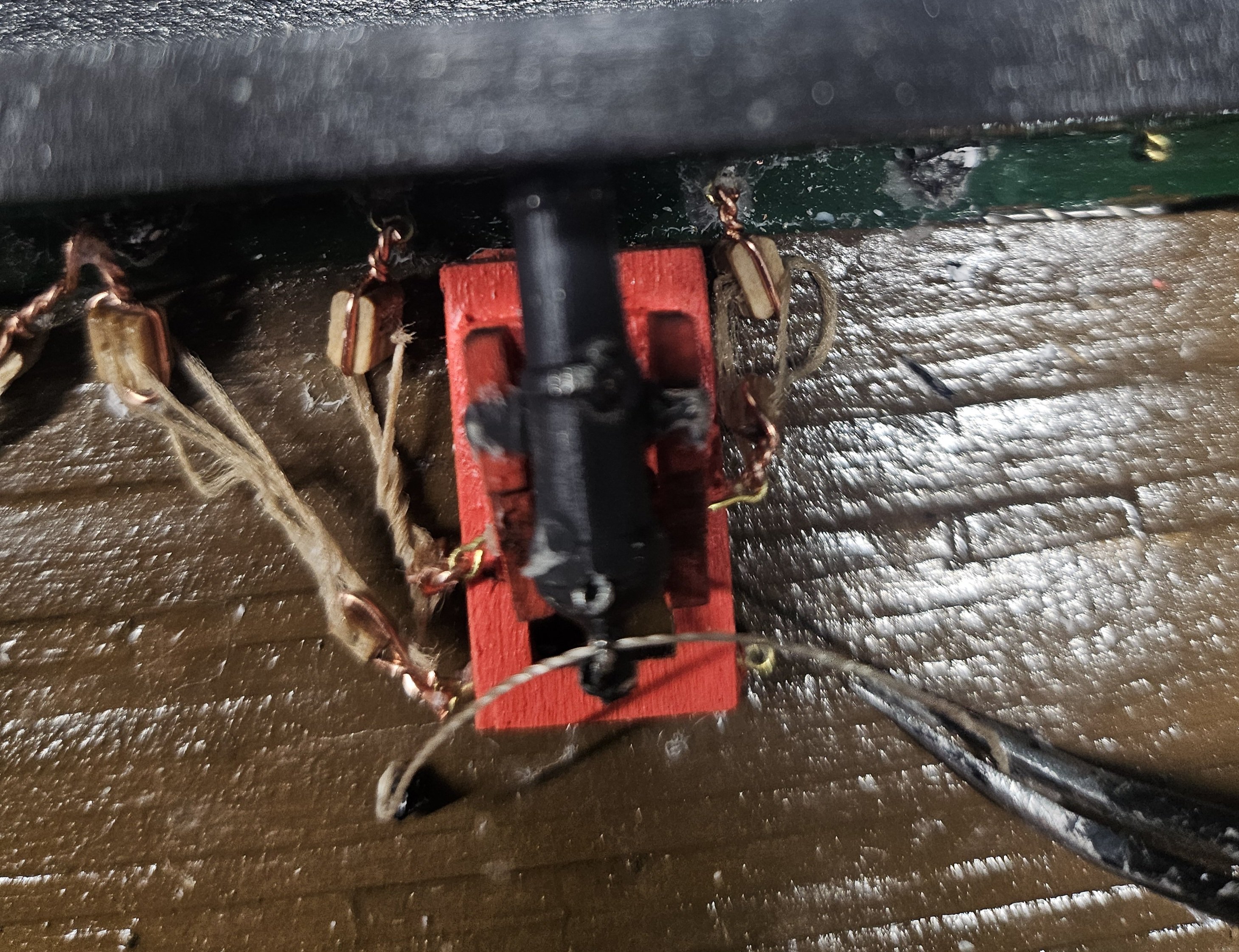
You did an amazing job with the chain plates. Also you carronades are incredible. The thread in the kit is definitely not high quality like yours. You got actual hooks and that was not part of the kit so I had to make those, but yours is so much better and really clean. None of the thread in the kit looks as nice as what you have and we're stuck with it because the holes in the blocks are not large enough for the good stuff. I like that you use eye bolts and think that's a better way to go, unfortunatelywe only get so many in the kit and 4 eyebolts areinstalled on the carriage, 2 in the back where the wheels are, and 2 in the middle wall structure supporting the cannon barrel. The we had to install 2 eye bolts, 1 on each side of the gunport opening, then we had to make these tiny fittings from polystyrene with 2 holes in it and those were glued in the center between every gunport horizontally. Then we had another fitting shaped in a rectangle with a one hole. These were glued between each eyebolt and the fitting with the 2 holes vertically. after those were painted black and glued, you had 2 lines connected from the eyebolt in the middle of the carronade to the eye bolts near the gunport openings. Then you had to rig 2 more lines that were longer connecting the eyebolts on the back of the carronade to 1 hole in the fitting that has 2 holes. The 2nd hole is for the next carronade next to the 1 you're working on. The final thread or rope is for the breech. That rigging line connects to the vertical fitting with the single hole and those are tied in one knot with a drop of glue and then routed through the hole on the breech of the cannon and then tied to the last vertical fitting with 1 knot and glue. So, there are 5 rigging lines for each carronade. You have to glue one of the hooks either on the carronade or the fitting otherwise they will keep popping off because you are manipulating the cannon and then trying to get the hook into the last eyebolt.So this is the challenge I have to deal with for the kit. Sure doing this by hand brings out a unique type of authenticity, but really, it's a pain in the A$$ because it takes a long while to make sure the lines are long enough and that can change for each carronade. Getting the right rope size is what's killing me right now. -
mtbediz reacted to a post in a topic:
USS Constitution by mtbediz - 1:76
-
USS Constitution by mtbediz - 1:76
rturcic72 replied to mtbediz's topic in - Build logs for subjects built 1751 - 1800
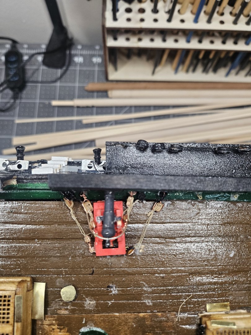
Jon, you're absolutely right. The glue does help, and the thread is still flexible. The challenge is making the size adjustments between the fittings on the ship to the carronades. So far, it has taken me two days to rig two carronades. The first one came out pretty decent, but not perfect because this is my first time working with very tiny parts. The second one was a little tough because I made them a couple millimeters longer than they should be, so I've been working around that. I also used the original thread for tying the breech. After seeing the first one, I decided to use a thicker thread instead. The original thread was already known to be inadequate. I use the original thread for rigging the carronades and the thicker thread that is fray resistant for the breeches. -
USS Constitution by mtbediz - 1:76
rturcic72 replied to mtbediz's topic in - Build logs for subjects built 1751 - 1800
You definitely make it look perfect. I started rigging the carronades on the deck and that has been a painful and time-consuming process. Trying to push thread through such tiny holes is just something else and lots of trial and error figuring out how long to make the lines so that when they connect the carronade to the fitting on the ship it looks tight and neat...none that I have accomplished yet, lol. I really don't know any easier way, but to move at a snail's pace and do it really slowly. -
I almost feel as if some parts are missing on purpose because at certain points in the practicum, you've learned some skills that would be used in those missing areas. So, maybe there was no mistake, but it's still a gap. It would be great if I had some of the big tools for woodworking. The best tool I have is by beloved 1000W Laser engraver and cutter that can go through 1/4-1/2 of wood. At least if I did my first scratch build, I could still do it by hand, but I would be able to laser cut my own wood and parts using the plans provided the plans are reliable. The only power tools I have are a good Dremel tool with all attachments, a small table saw, a small wood lathe, and a small grinder and belt sander machine. I've only used the wood saw and grinder and sanding belt once. And I think that's only because half of my free time is at night and when everyone is sleeping, I don't like to make a whole lot of noise. I don't think my small table saw could cut or mill wooden strips, or at least I'm not sure how to do it, what attachment or blades and sizes of blades to make my own strips for decks and/or planking. I could probably find how to do this on You-tube. Anyway, thanks for the compliment and knowing that it's been mainly by hand, makes me feel more valued for an accomplishment like this as well as knowing this is not only my first build, but also told by many experienced builders one of the most difficult to do and then recommended I start with the 3-boat kit as a precursor. I guess what motivated me was that in one of the forums it said that it was rare for a new person to finish their wooden ship, especially the Conny, and there have been only a couple rare instances of someone new able to pull this off successfully. I was drawn towards the challenge of doing it, as well as challenging myself and abilities that I may not have discovered before. I find it very relaxing doing this but also feel the same frustrations as others in certain areas of the plans and practicum, even though I have to give credit to the practicum at getting me this far. I'm very happy being part of this group of like-minded folks in a somewhat rare type of model building/assembling compared to plastic models that most of us started with.
-
USS Constitution by mtbediz - 1:76
rturcic72 replied to mtbediz's topic in - Build logs for subjects built 1751 - 1800
Literally amazing and impressive! -
USS Constitution by mtbediz - 1:76
rturcic72 replied to mtbediz's topic in - Build logs for subjects built 1751 - 1800
Wow, I'm impressed with the craftsmanship...definitely first rate! And this is what separates the scratch builders from kit builders. We had to take the deadeyes and wrap wire around the deadeye and then solder that to the brass strips they placed in the kit. This makes me wonder when someone sees the perfect scratch builder Conny versus kit builders, mostly using hand tools and imperfect, which one would appeal more to someone if they were in a museum and view both versions? I personally would lean towards the scratch build because it's still based on plans that are in scale just like kit builders. Making it as clean as yours brings in a lot of appeal. The flip side to this I think is that there a folks out there that like the imperfect hand build because the real Conny is not symmetrically perfect and you can tell everything is still handmade on the ship to preserve its look. I've had friends tell me how the ship looks awesome, but I always say none of it is perfect and point out the flaws in what I've done. There are several areas I had to reconstruct or modify to make it work and make sure it looks like it's supposed to based on the plans. I had to improvise a little recently because of the hooks and rigging for the carronades, but essentially accomplishes the task at hand. -
USS Constitution by mtbediz - 1:76
rturcic72 replied to mtbediz's topic in - Build logs for subjects built 1751 - 1800
I'm sure your deadeyes are much better quality than what they give in the kit. I disintegrated several of them along the way, lol. -
USS Constitution by mtbediz - 1:76
rturcic72 replied to mtbediz's topic in - Build logs for subjects built 1751 - 1800
Mustafa, are you planning on rigging?