eurekapaul
-
Posts
15 -
Joined
-
Last visited
About eurekapaul

- Birthday 08/29/1953
-
 mtaylor reacted to a post in a topic:
Micro-Mark Desktop Dust Collection System
mtaylor reacted to a post in a topic:
Micro-Mark Desktop Dust Collection System
-
 In my garage woodshed, I'm pretty careful to collect and minimally breathe dust. However, I'm not as careful in the shipyard, although I run a small HEPA filter. To the end of keeping my lungs working well, I'm considering buying the Micro-Mark Desktop Dust Collection System. If anyone has used it, what do you think? In particular I'm interested in how well it works and how much noise it makes. Also if anybody has any opinions on it, please feel free to express them. Thanks, Paul
-
robert952 reacted to a post in a topic:
Fairing question on Model Shipways Syren
-
mtaylor reacted to a post in a topic:
Fairing question on Model Shipways Syren
-
allanyed reacted to a post in a topic:
Fairing question on Model Shipways Syren
-
Thanks Chuck! It seemed like I had to take off way too much to get it to fit. I know I need to do a bit more beveling. I just didn't want to go any further without some feedback. Also thanks Alan. I appreciate the effort and time it took in answering me. I should have been more clear about the model and been more descriptive about what I was asking about. Next time I'll put in all the information. Paul
-
mtaylor reacted to a post in a topic:
Fairing question on Model Shipways Syren
-
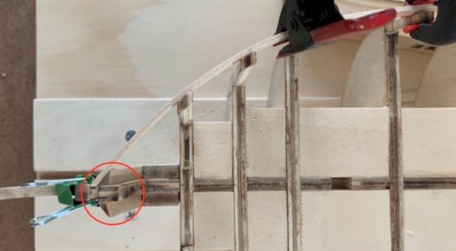
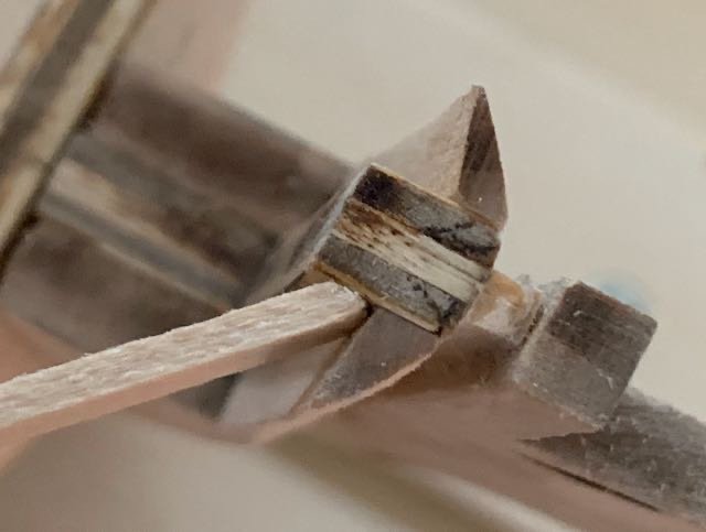
I’ve recently started working on the Syren. I have a question about the bevel at the stem. As you can see in the pictures, I’ve already gone way over the laser lines and the battens still don’t properly line up. I can’t figure out what I’ve done differently from other builds. Before I go any further, I thought I’d see if anybody has had this problem and knew what was wrong. The rest of the bulwark beveling seems fine. Obviously I’m going to have to shim it, but I figured I’d ask before going any further and avoid potential problems further on. Thanks for your help.
-
Cathead reacted to a post in a topic:
NRG Half Hull Planking Project by eurekapaul - 1:48
-
dunnock reacted to a post in a topic:
NRG Half Hull Planking Project by eurekapaul - 1:48
-
RossR reacted to a post in a topic:
NRG Half Hull Planking Project by eurekapaul - 1:48
-
robert952 reacted to a post in a topic:
NRG Half Hull Planking Project by eurekapaul - 1:48
-
robert952 reacted to a post in a topic:
NRG Half Hull Planking Project by eurekapaul - 1:48
-
Hi Ross, I've been thinking of using boxwood strips above the wale for this project, as I have some left from my Albatros build. It would give me some more practice with edge bending for the Syren. For the Syren, I'll use the basswood planks that come with the kit that are covered by the copper plates. For the exposed planking, I'll use Alaskan Yellow Cedar strips. I really don't like cutting planks, but I wanted to learn it and get a feel for it. -Paul
-
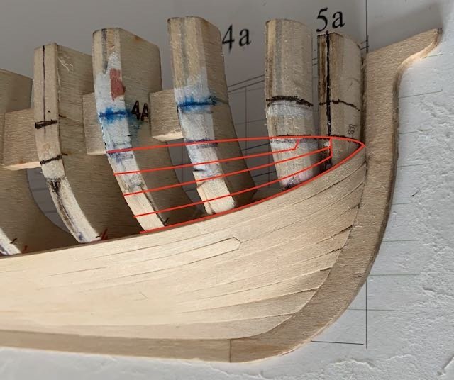
Time sure seems to fly, particularly this time of year. I’ve been making progress and come to a decision about about how perfect I want to make this project. When I first started this model, I wanted to make it a display piece. After installing and re-installing the bow planking four times in the lower belt, I’ve decided that I’d stop being so particular and continue to plank. My purpose for this project and its intent is to learn how to plank and take this knowledge and apply it to future models. As the following pictures show, my tendency is to make the planks too wide — actually way too wide. Apparently, I can’t help myself. So thinking about this with some self-recrimination, I see that I have three choices: abandon the model and go on to my next project, rip out (deconstruct) most of the planking and do it right, or continue and make the best of it, even if it shows all my mistakes. I have decided on the third choice for the following reasons: I don’t want redo the planks again and more importantly I want to get on to building the Model Shipways Syren. Being able to see the consequences of my choices will be a reminder to do it right. In this case, my biggest error is shaping the plank by look the plank and not paying attention to the belt lines. Learn how to better shape the planks so they fit tightly. (There a various places where you can see small gaps between the planks.) At this point, I can never get the bottom of a strake’s curve quite right. There’s always slight bit of side-bending needed. Improve my observation of the planks before gluing. One tendency I have is not getting the plank flush with the plank below it. I always seem to miss one place. Keep on improving my dexterity. This has definitely improved as I’ve continued. After getting this far I am able to cut the planks almost wobble less. My plan after installing the wale Given that the second belt has already reached the wale line, this picture shows what I think will allow me to practice drop planking: Hopefully, this will work and help build my skills and patience. 😀
-
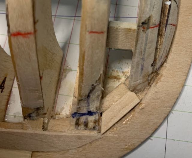
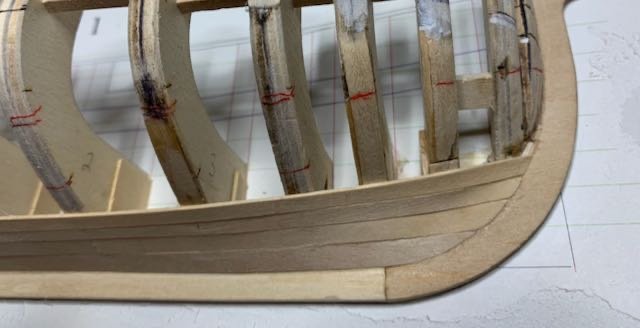
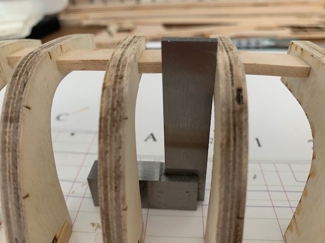
Back to where I was Eric, I applied your advice to my redo with better results. Thank you! Since I wasn’t happy with how the planks above the garboard looked near the bow, I removed them and redid them. Part of the problem I was having was that the planks weren’t quite lying correctly. In particular, the rabbet was too deep so that the bottom edge of the broad strake was partially underneath the garboard. This picture shows the shim I added before shaping it to match the rabbet and allow the broad strake to fit correctly. Besides adding a shim, I made a guess that frames 4 and 5 weren't quite right. This turned out be true. (But I was prepared to add more shims.) Although not perfect, I think the planking looks better. Sanding should clean them up enough - I hope.
-
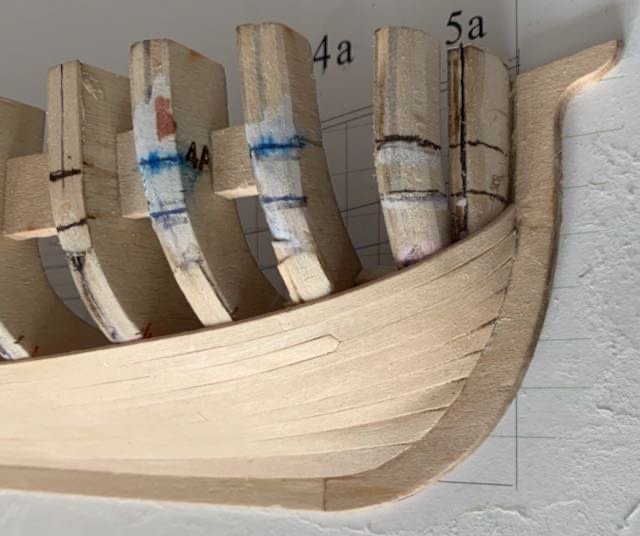
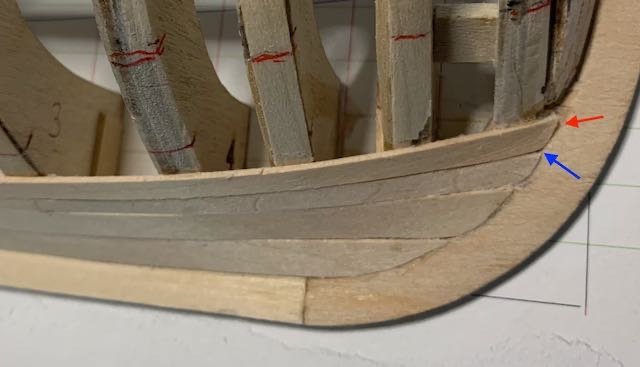
Thanks everyone for the comments. It is indeed more challenging than I anticipated. I enjoy figuring things out. One of my biggest challenges is my impatience, as you'll see below. Laying the garboard and broad strake. Following my tradition of not quite doing things right, I laid the tape for the garboard strake. In this case I put the edge of the tape in the rabbet. However, after I pulled it off the model and put it on the planking material, I realized it would probably be better to have the tape overlap the rabbet and draw a line to mark the rabbet. In the above picture you’ll notice that there is a mixture of colors on the frames near the bow. This is because I drew the wale lines in the wrong place and with a felt pen. I used a machinist square to mark the wale lines from the plans, but when I ran a batten along the upper wale lines, it wasn’t smooth. I then drew new lines using a blue sharpie, which I had on hand. Well, the sharpie was way too wide and it bled. My impatience won and what I was avoiding became imperative -- going to the art store to get another pen. After a couple of tries on most of the planks, I was able to get a decent garboard laid. Laying the next planks I'm definitely having trouble with the planks at the bow. You can see the gaps. I've made four planks for the uppermost strake and although I've gotten closer, it still isn't right. Also from this angle, the broad strake looks extremely big. I hate to start removing planks, but I think I'm going to have to. Does anybody have any advice, particularly regarding the gap that the red arrow points to, I'd really appreciate it. Paul
-
Thanks Eric! When I was a technical writer, I seemed to have a knack for making mistakes. This was good for users, as I could point out potential pitfalls. I do wish though, I wasn't continuing this tradition so fervently in my model building. Paul
-
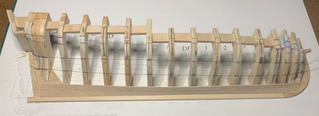
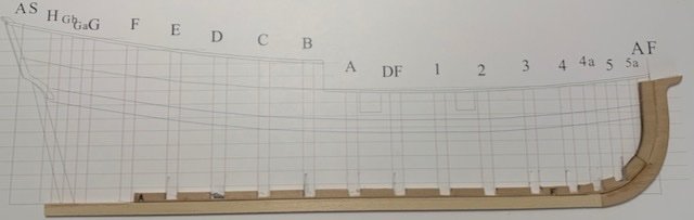
I'm back. I had a more than a slight detour. The basement flooded from a broken pipe to an outdoor faucet. It didn’t freeze; it was not correctly soldered and when replacing the faucet, it came apart. Fortunately, it was clean water. So I spent two and a half weeks opening up the wall and replacing the wet insulation. I also had to remove the laminate flooring to dry and clean it to make sure no mold would grow. Reinstalling was a new experience. Besides painting the new drywall, I also repainted all the trim and doors because my wife didn’t like the original color. Fairing the frames To rough in the frames I used a batten. This picture shows an example. The roughing in when pretty well. I then used the method in Toni’s log of first using chart tape and thread to hone in the right shape. That seems to go well and and didn't require much shimming. Unfortunately, I forgot to take a picture showing the chart tape. I did take an intermediate picture showing the center lines (before starting the more refined fairing). Continuing to follow Toni’s technique, I started using a batten to tweak the fairing. The batten showed I had taken off way too much material. As you can see in the picture, I added shims and shims on top of shims. I don’t know why it was so different from what the first method. I really wish I hadn’t forgot to take a photo because then maybe it would be obvious what I did wrong. At any rate, I’m ready for the next step.
-
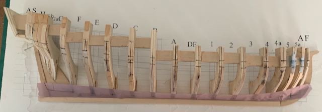
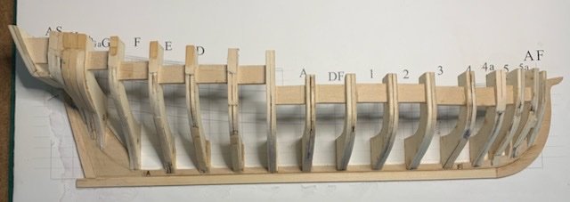
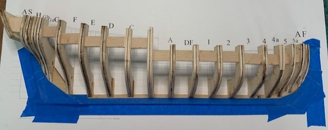
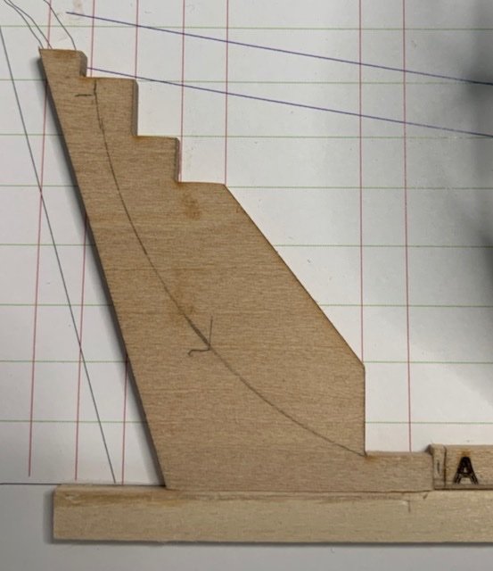
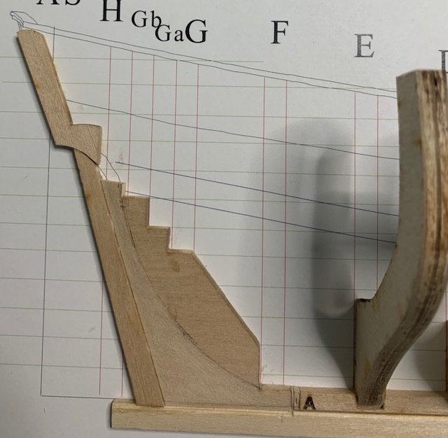
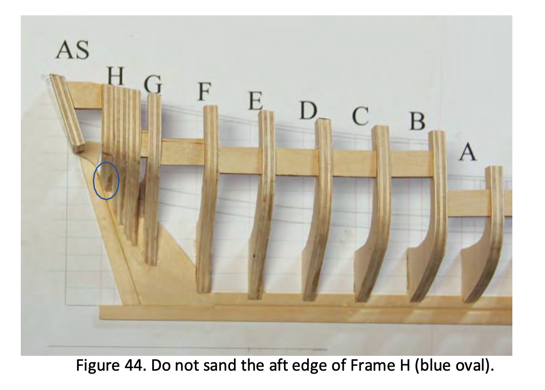
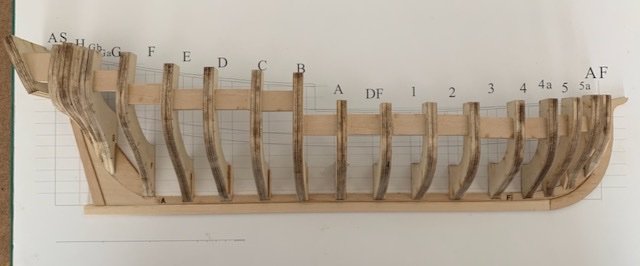
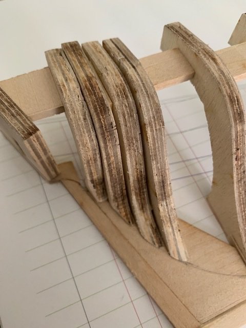
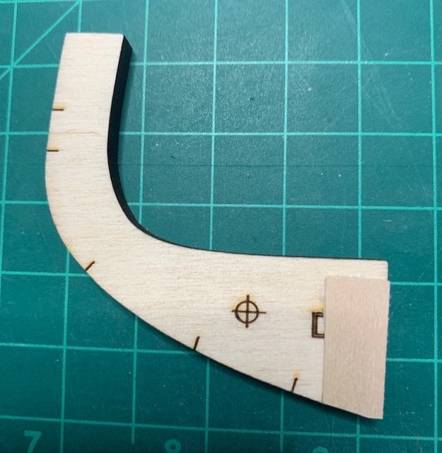
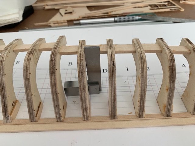
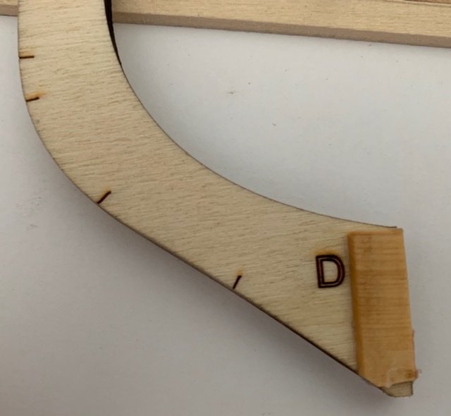
I redid Frame A. After removing the spacers, I saw that the it did not quite line up with the red vertical line, which resulted in a slight twist. Going forward, I think I need to (1) look more carefully and (2) view whatever I’m working on from all possible directions. Bearding Line I noticed two problems right off. First, the notch does not line up with vertical red line on the plan, plus it's not as wide as the frame. Second, the bottom of the L-shaped piece dids not align with the top of the keelson. The bottom misalignment was probably due to me taking off too much wood. I had to remove some material to make the angle of the aft edge of the L-shaped piece match the plan. I used a French curve to draw the Bearding Line. I have three curves, all survivors of several decluttering episodes over the last 30 years. After my earlier experience with cutting the rabbet with a chisel, I opted for sandpaper to create the bearding line. It took a few minutes. I almost removed the wood from the wrong side. Apparently, there must be something called late onset dyslexia. Installing the remaining Frames In her instructions Toni warns not sand the aft edge of Frame H. This instruction is on page 25, several pages after the framing section. As I didn’t see this until after tapering the frame, I removed too much material. I added a shim to get it a proper gap. Hopefully, it's enough. I’ll see when I add the counter. The stemson required a notch as mentioned in the instructions. I started to remove all the wood to match the frame line but determined I could more easily create a notch. Here is a picture of the finished framework.

-
It must be related to the number of required posts. I tried both Safari and Chrome on my laptop. Thanks for letting me know.
-
Is signature not available? I've looked at both my Profile and Setting pages. Here is what I see on my Settings page:

-
eurekapaul changed their profile photo
-
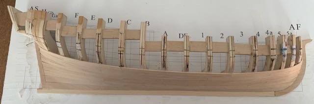
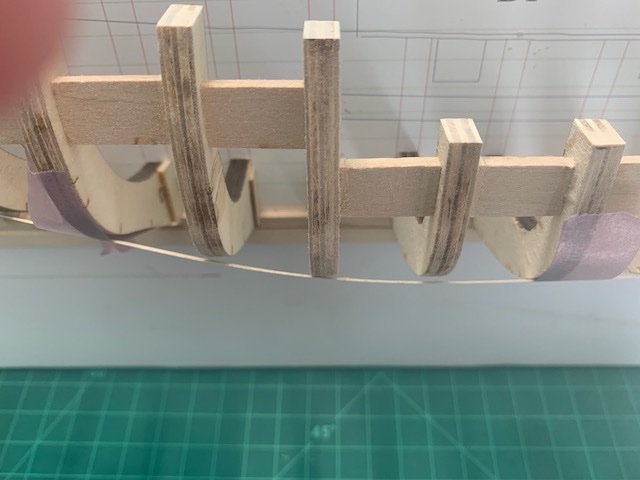
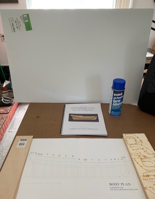
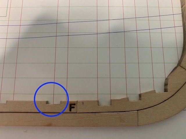
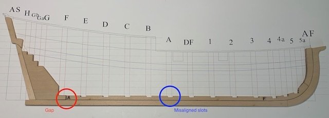
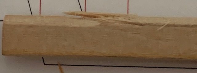
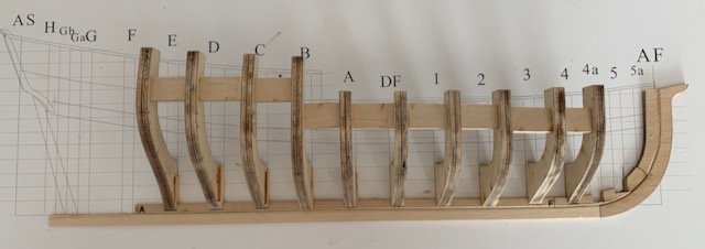
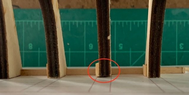
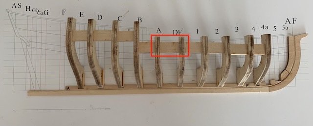
While working on the planking for the Albatros by OcCre, I realized I needed more instruction on planking. So I joined the NRG and ordered the planking kit. Now, several months later and after finishing the Albatros, I’ve begun. Bookmarks My first step was to bookmark all the Half Hull Logs. After looking at the logs, I eliminated the ones I didn’t think were useful. (No disrespect intended.) Print and bind The next step was to print and bind Toni’s instructions. After printing the manual on my laser printer, I took the printed sheets to Office Depot. It was only a few bucks and I was surprised how fast the binding took; Literally, it took two minutes. Now I was ready to start. Unfortunately glueing the plan to the poster board turned out to be much more of an effort than it should have. First, the spray adhesive was partially clotted. I carefully cleaned out the nozzle but that didn’t help. The spray can had been lying on it’s side in a drawer for years and the adhesive came out in clumps no matter what I tried. So off to the store to get new adhesive. Next when I was attaching the plan to the board, the plan slipped off my fingers and resulted in bubbles. I emailed Mary at NRG about getting a PDF to print. Amazingly, she replied within an hour with a PDF file. As the plans are larger than my printer’s capabilities, I debated whether to print two sheets or go to the copy store. I decided that it would be less error prone to glue down a single sheet than sheets. Subsequently, I went online and uploaded the PDF to the local Office Depot. A couple of hours later, a printed copy. My second attempt to attached the plan to the poster board went perfectly. Starting putting things together When I aligned the fore keelson slots, the slots did not match up as shown in the picture below. I removed some material from the fore keelson to align the first slot. After removing the material to align the first slot, a gap was created between the keelson and the dead wood. I then added a filler piece. As you can see, a number of slots were not aligned with the plans. Whether the misalignment was a problem in the laser cuts or the printed plan made from the digital file was slightly stretched, I don’t know. Regrettably, I threw the original printed plan away. No matter the cause I decided to fix it by cutting the aft end of each slot to align with plans. Then when installing the bulkheads, I could add a filler piece. The rabbet I wanted to create the rabbet using a chisel to develop my skills. I practiced carving the rabbet on a piece of scrap wood. Thinking I had it down I proceeded to the keel itself. It didn’t go so well. Fortunately, the local art store carries basswood and for $1.08 I had two pieces of the same size, albeit without the hump. After adding the hump, I opted for sanding the rabbet. Even if I had a higher level of dexterity, I think that sanding would have been the better choice to begin with given the tiny size of the rabbet on the keel and keelson. For the stem and stemson, I used a combination of a chisel and sanding stick. Deepening the slots in the keelson I found it difficult to not damage the poster board. My only concern about this was how it might impact the frame alignment. This didn’t turn out to be a problem. Placing the bulkheads As mentioned earlier, to align with the plans nearly every slot was too wide. To compensate, I glued filler pieces to most of the frames. Frame alignment error 1 After installing each frame and starting to install the spacers, I noticed one frame wasn’t lining up with the others. On closer inspection, I had installed it at an angle. Frame alignment error 2 I was glad I was using PVA glue so I could remove the frame. I may have been a little too impatient because after removing the frame, a small and critical piece of the filler broke off. But perhaps it wasn’t my impatience, as the filler piece was flimsy wood. I replaced it with a stronger wood. Hopefully, I’ll remember to used better wood for filler pieces in the future. Most of the spacers required removing some of the material. However, between frames A and DF, and frames DF and 1, I had to add shims. With the machinist square the frames look vertical. However, when visually sighting these frames, it looks like frame A is not vertical. I think I’m going to remove frame A and redo it.

- 17 replies
-
- 11
-
-
Thanks everyone for the warm welcome. Hi Chris, the Eureka connection is indeed a connection to the city in northern California. Way back in the 90's, my wife and I lived in there. Shortly after moving to Eureka, I signed up with AOL. During the phone call signup, when the agent asked me for a username and not having thought about it before, eurekapaul popped into my head. Even though Niwot's Curse brought us back to Boulder a few years later, the email address stuck. --Paul
-
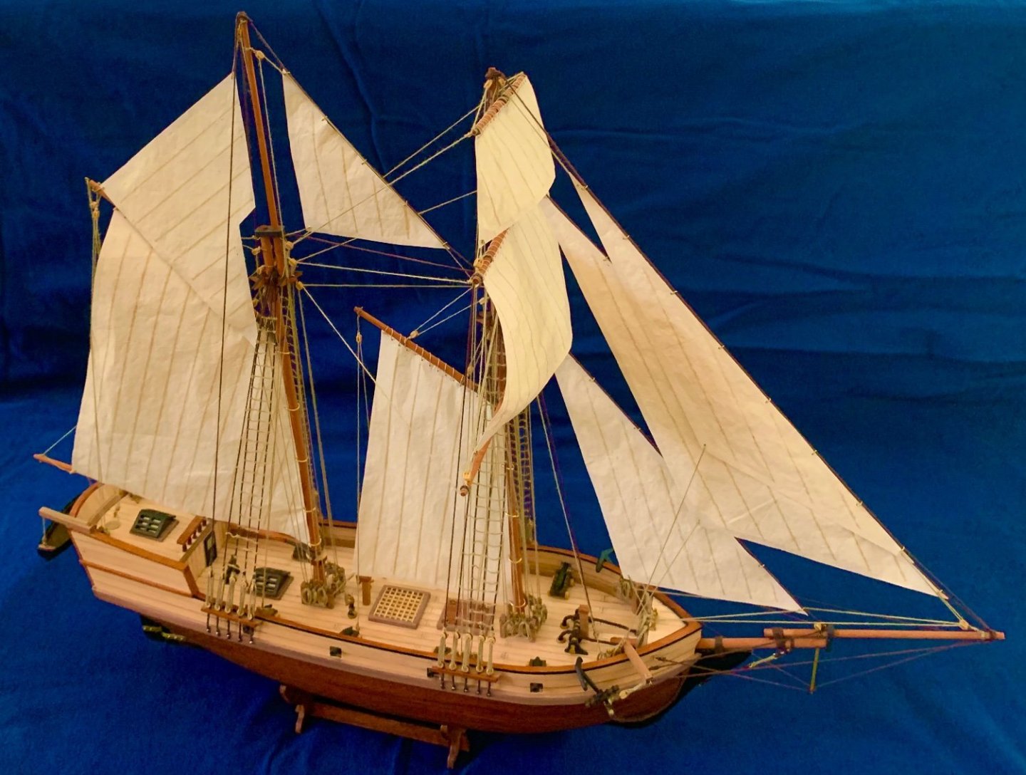
Hi, it's far past time I introduced myself, since I've been following this site for over a year. My name is Paul Tepley and I live in Boulder, Colorado. My interest in this hobby stems from a print my stepfather had of the Sea Witch clipper ship under full sail. It has stuck with me for over half a century. Recently, I finished building OcCre's Albatros. After breaking both bulwarks and some other planking, it became obvious that I needed more instruction so I built the Model Shipway Sailing Pram and Lobster Smack kits. (A big thanks to David Antscherl!) I have resisted creating build logs because I was a technical writer for over 36 years and I needed a break. A few days ago, I started the Half-Hull Project. It will have build log; I've already taken the pictures of my first steps. After (hopefully) learning to properly plank, I'll start on the Syren by Model Shipways, which I bought a few months ago. After that, maybe I'll tackle a clipper ship. Going back to the Albatros, I did a bit of kit bashing. I wanted to try out better wood, so I bought some boxwood from Modeler's Sawmill and used it for the planking above the wales. Also, the cloth sails provided by OcCre was way too heavy so I made my own from Silkspan using Tom Lauria's method. Lastly I have to say that the support, knowledge, talent, and skill by members of this site amazes me. Thanks to everyone who contributes. You've made my foray into model ship building a lot more enjoyable than thought it ever would be. --Paul Here is a screenshot of my Albatros: