MORE HANDBOOKS ARE ON THEIR WAY! We will let you know when they get here.
×

Panagiotis
-
Posts
73 -
Joined
-
Last visited
Content Type
Profiles
Forums
Gallery
Events
Everything posted by Panagiotis
-
 Thank you John. I'm afraid I might disappoint you. It wasn't in my plans to make a build log for the Liberty model, so I haven't kept many photos from the beginning of it. In addition, I don't want to lose time with the build log, as I said I have to finished as soon I can... Maybe I could do a summary build log, when I finish the model. Thanks
- 116 replies
-
- 2
-

-
- kilkis
- mississippi
- (and 2 more)
-
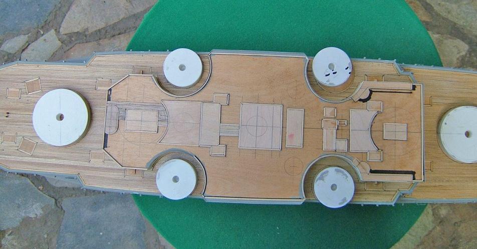
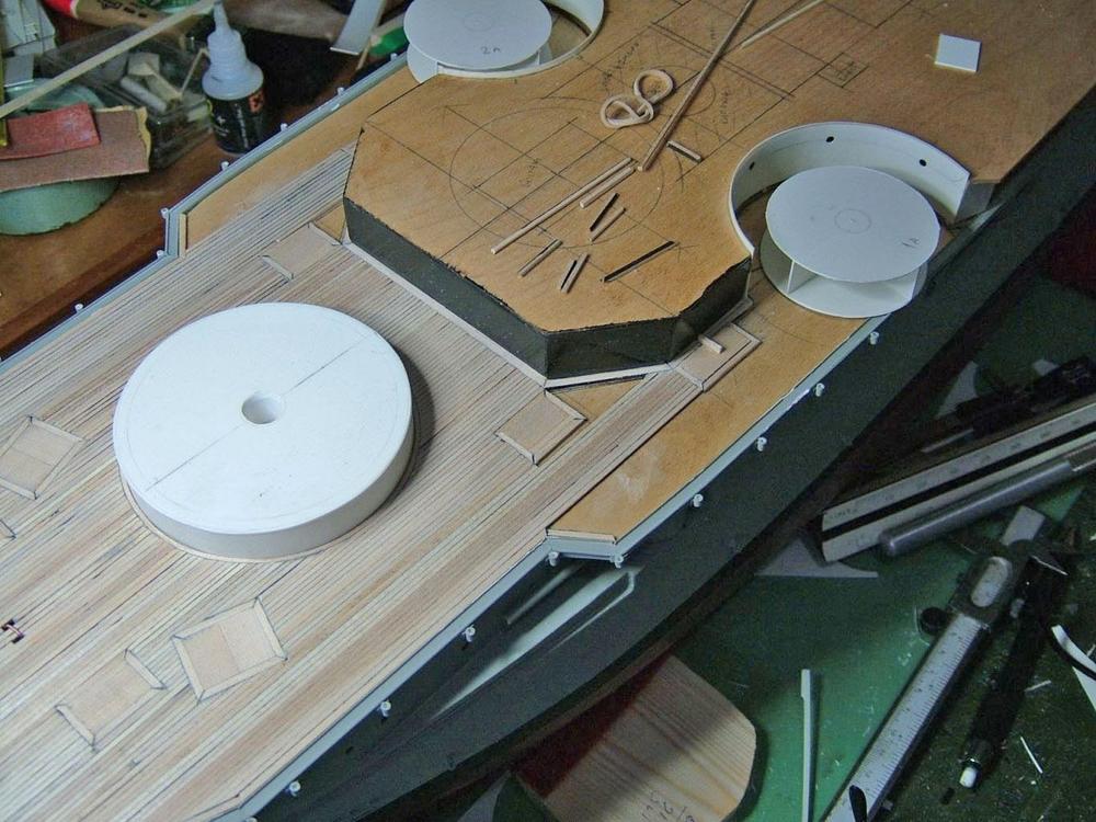
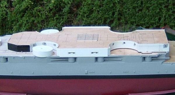
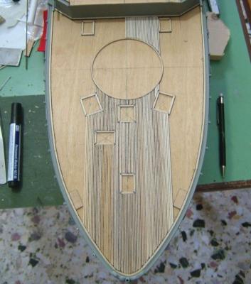
Hi all. These past few days I formed and planked the upper deck. I constructed the sides of the deck, the turrets and their openings leaving the gun barrels for later. I had doubts whether this deck was planked but a father of a friend of mine (106 years old) he does remember and confirmed me that indeed was planked. He was captain in a tugboat and he had visited both ships, Kilkis and her sister Lemnos, many times… Again it took me many hours making a monotonous work… I would like to inform you that maybe will be some delay in Kilkis’s progress because at the same time I’m working also constructing a model of Liberty ship.The model is constructed for that previously referred friend of mine and is going to be named with his father name (Captain Dimitris). Although he (Cap.Dimitris) doesn’t believe that he will see it finished, I would like to do my best… Thank you


- 116 replies
-
- 4
-
-
- kilkis
- mississippi
- (and 2 more)
-
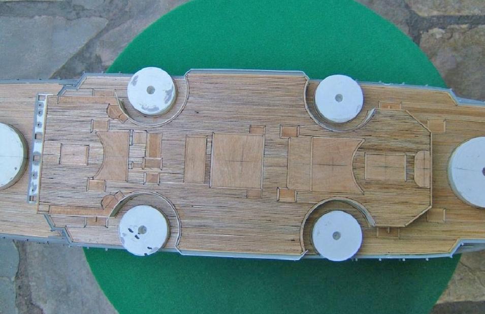
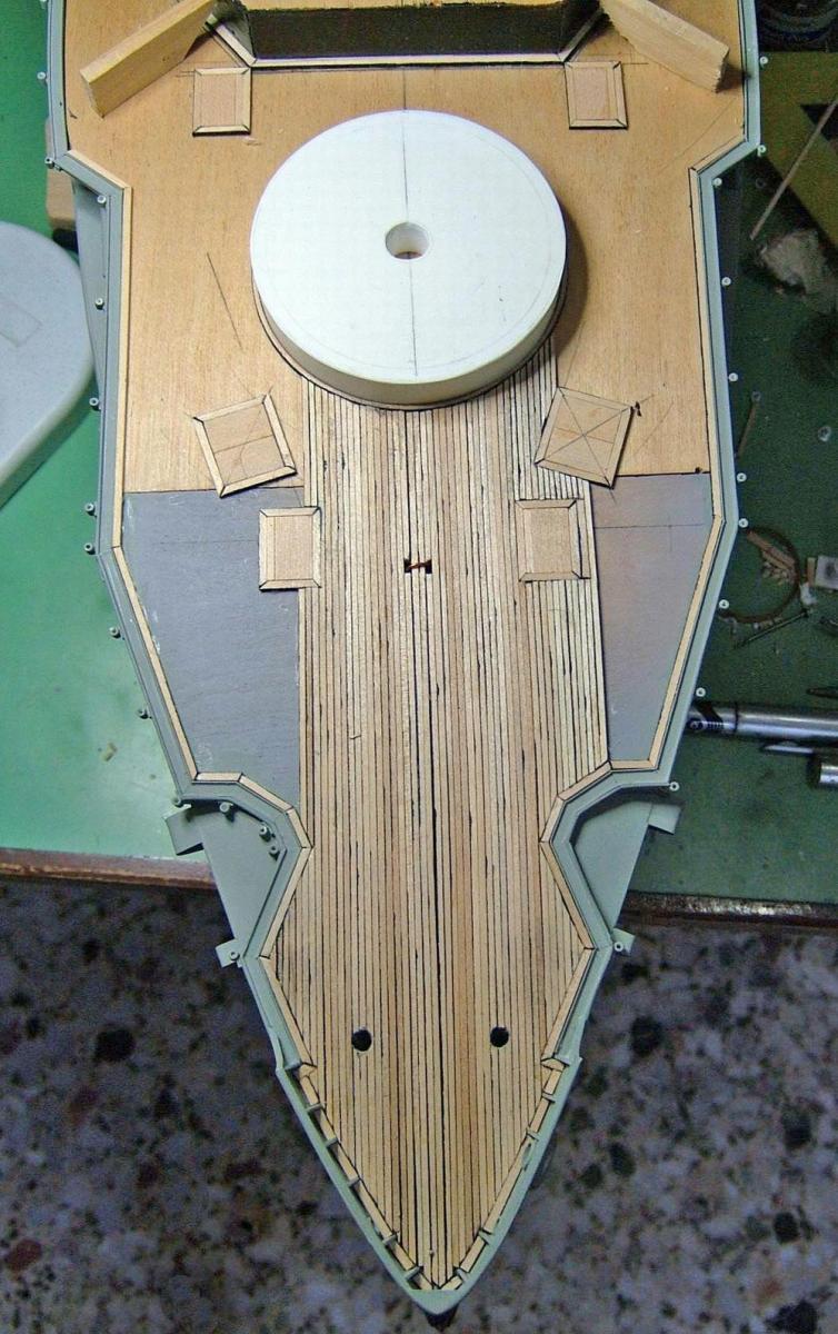
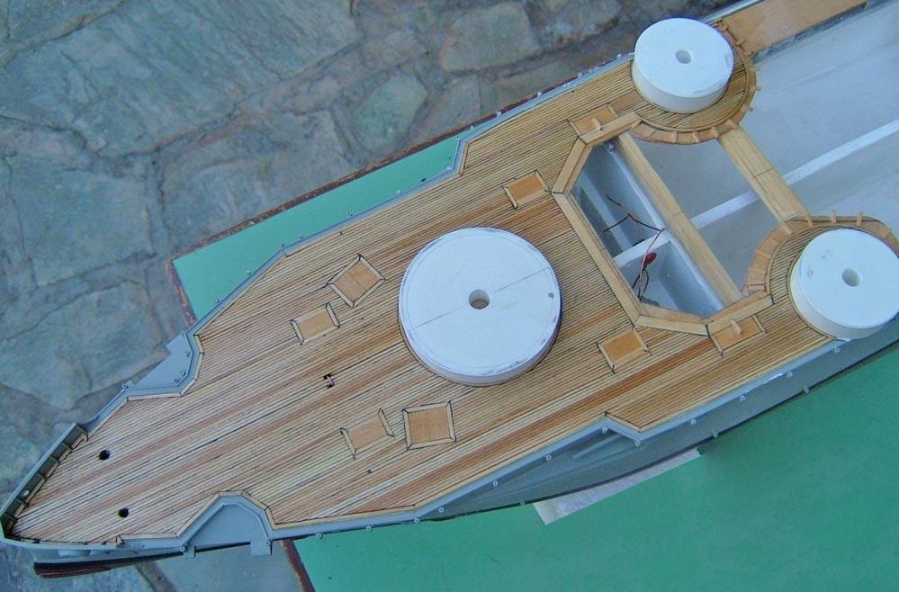
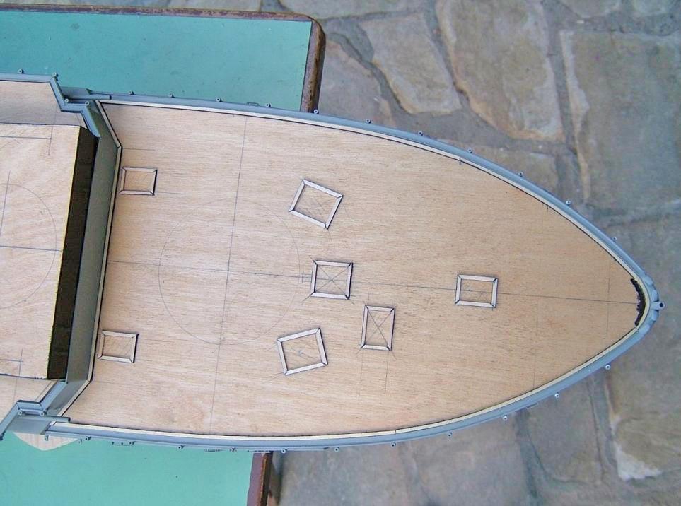
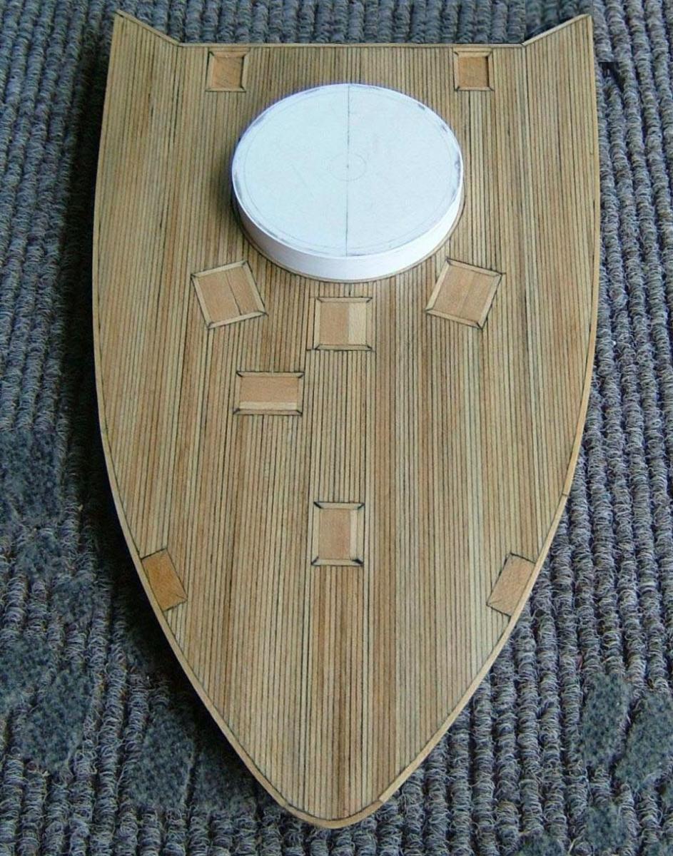
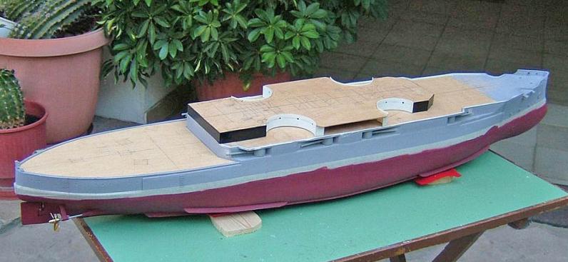
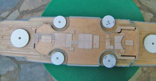
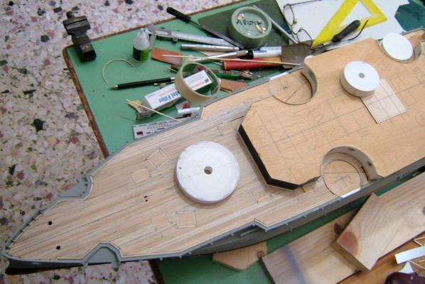
Thank you all for your comments. Your kind words gave me what I needed, to continue with the planking of deck at the prow... ........................................... It was much harder than at stern's, since there are more turret bases. Again the turrets were initially constructed. ................................... So far I have used 50 meters (164 feet) of 1,5 X1,5 wooden balks, planking those decks. It is a tedious stage, but had to be done... ...................... Thanks


- 116 replies
-
- 7
-
-
- kilkis
- mississippi
- (and 2 more)
-
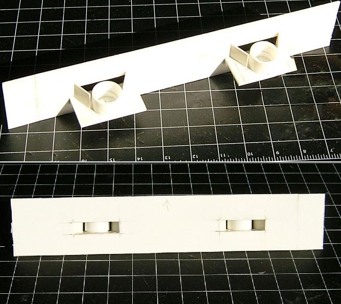
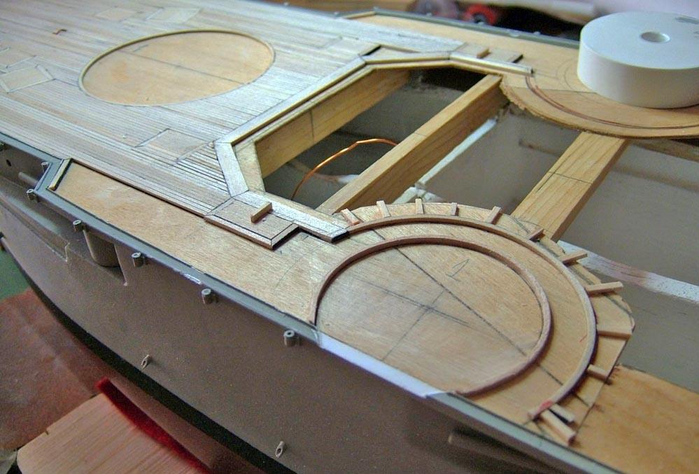
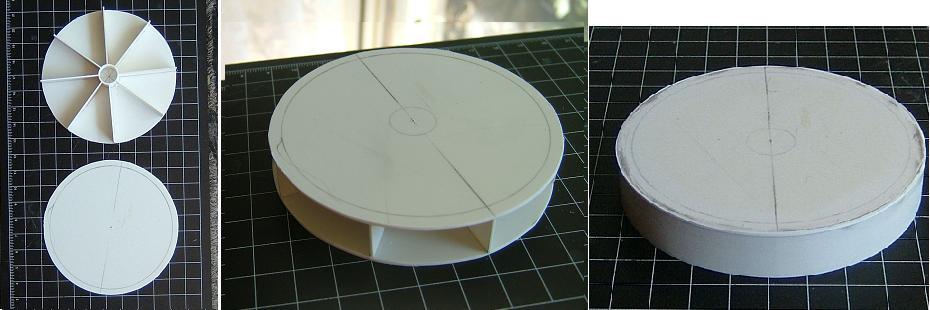
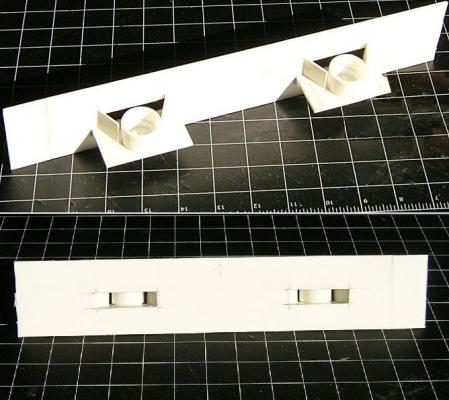
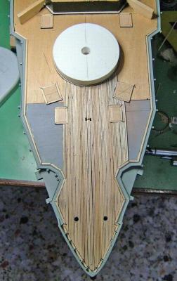
Hi all. It was the turn for the stern to be formed. In the photo you can see the frames of the openings that have been built with 2X1, 5 mm wooden balk, while the rest deck will be planked with 1.5X1, 5 balks. Before proceeding with the planking, I had also to construct and place a wooden ring as the edge (around the base) of the rear gun turret. I decided to construct the base of the turret, because as I thought, it would be a good guider and would help me a lot. The cyclical base was mainly made by two pieces of plastic that were placed together and were reinforced by other smaller pieces between them. Then its surface was used to form the wooden ring and it was also used as a support, helping gluing the ring at the right position on the deck. Now I was ready for the planking. ............................................................................................ Thanks


- 116 replies
-
- 5
-
-
- kilkis
- mississippi
- (and 2 more)
-
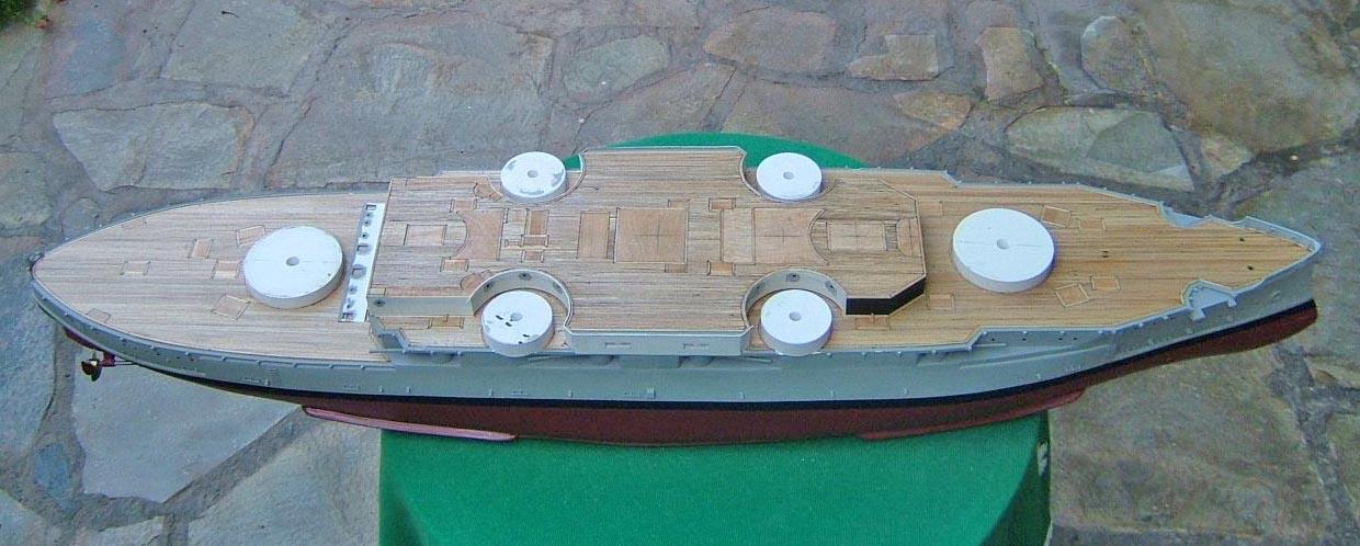
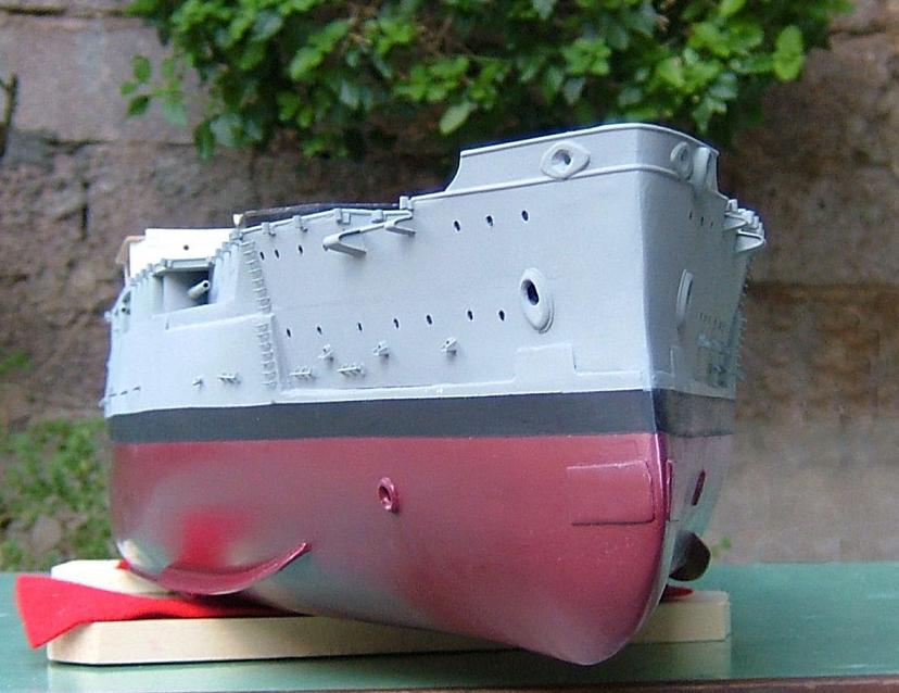
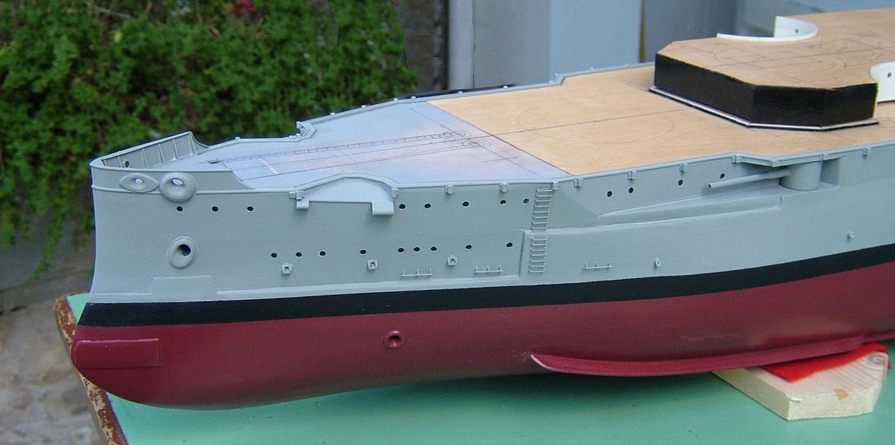
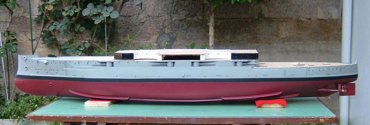
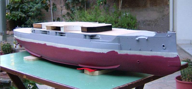
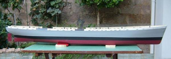
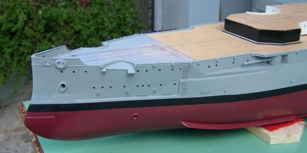
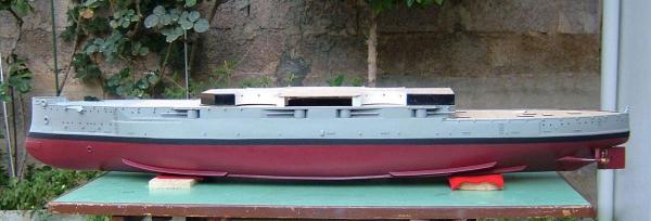
Hi all. Small progress painting the black strip above the waterline and unmasking the tapes from the rest hull. ........... Thanks

- 116 replies
-
- 5
-
-
- kilkis
- mississippi
- (and 2 more)
-
Thank you all mates. Ed, I use mat colors of “Humbrol” and such as No 64 for the gray and “Wine” No 37 for the color below the water line. At the end, I apply all over the paints, a coat of colorless mat varnish of "Humbrol" again. Thanks
-
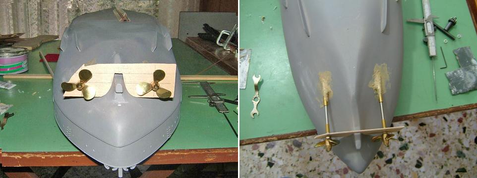
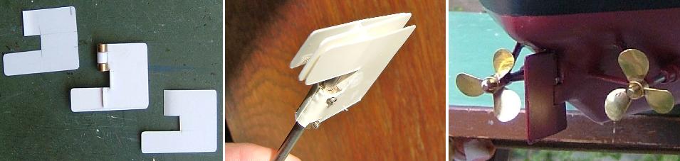
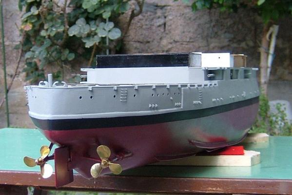
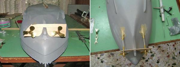
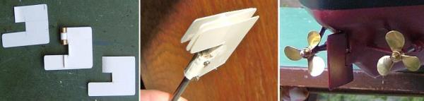
Thank you for your comments and your "like"... It's only a few days when I received the propellers and their axles and I got down to work. I made also the rudder using three pieces of plastic, to form a box at the proper shape and thickness. This box contains a small tube where the axle of the rudder, will be secured by two small screws. The rest space, was filled with putty. Waiting for the order of propellers, I made some work on an upper deck and I started painting the hull. Thanks


- 116 replies
-
- 4
-
-
- kilkis
- mississippi
- (and 2 more)
-
Some progress with prow details, grouting and priming. Thanks


- 116 replies
-
- 3
-
-
- kilkis
- mississippi
- (and 2 more)
-
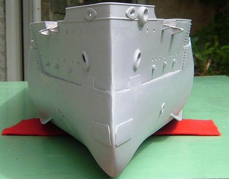
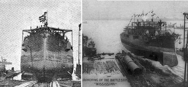
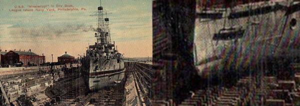
Hi all. After a double check of my drawings and some additional research, I have come up to some clues. Most significant is that In the lines of the magazine is written: The reason that the muzzles appear pointing forward, in the previous launching photo, I think is the angle that the photo has been taken and as she was moving backward and down to the sea. Initially I thought I have done a mistake on the model, but watching again her photos and photos from other ships, I think I haven't. As you can see in the below photo, with the ship in a dry dock, there is no angle apart from the given sense because of the shape of the hull. The photos below show the USS Texas in her launching. I think it’s understandable the different sense that is given on every photo, on the position and the angle of the muzzles. Ending with some final thoughts: There was no need to be pointing forward, since there was the ability of gyro angle settings. The forward pointing muzzles should have been drawn and built in a relation with the hydrodynamic of the hull. Thanks

- 116 replies
-
- 1
-
-
- kilkis
- mississippi
- (and 2 more)
-
Of course Brian...And yes, I think you are right... Seeing again the photos of her launching, I also noticed I have missed the right angle ... I see whether I can do something... Thank you

-
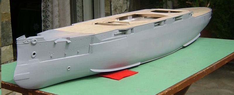
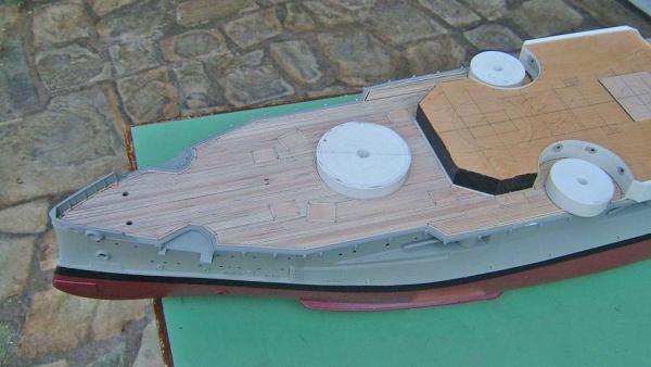
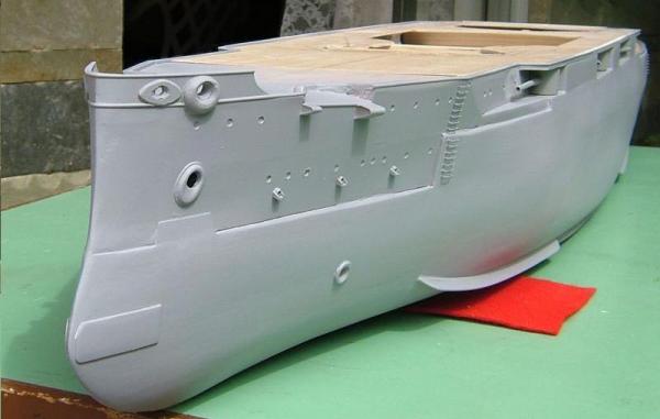
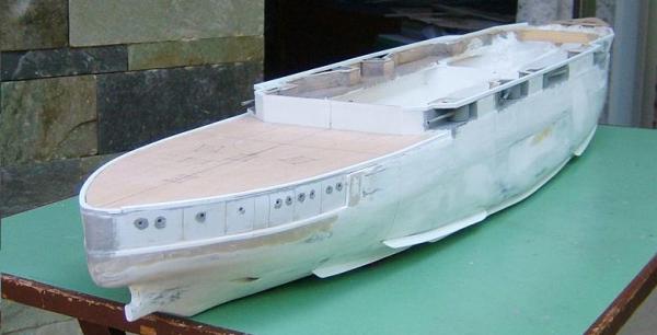
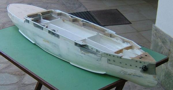
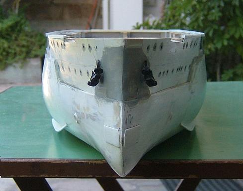
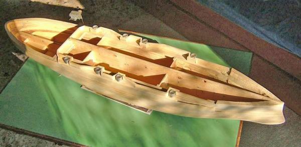
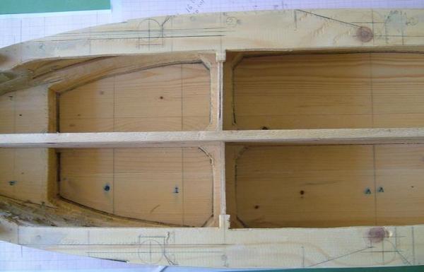
The work goes on. The hawseholes, the muzzles of the torpedo tubes, and the side guns are placed. What followed is a short wall at the perimeter, which will determine the position of the main deck, which a small part of it has already been set at the prow. The aft lower deck has also been cut and placed but only temporarily. Certainly, I’m referring to a shaped piece of plywood, on which and in time, glued planks of 1.5 × 1.5 mm are going to give the final form. The rear deck is planed to be removable, giving an easy access to the "engine room". In contrary the main deck will be unmovable, but not for the part of the superstructure, and so there will be another open for to the batteries. View of the starboard. The empty spaces before the short wall, are going to be the places for the spare anchors. View of the rear-starboard. Pencil marks for some future fittings are visible on the deck. Thanks

- 116 replies
-
- 1
-
-
- kilkis
- mississippi
- (and 2 more)
-
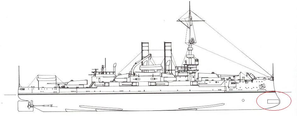
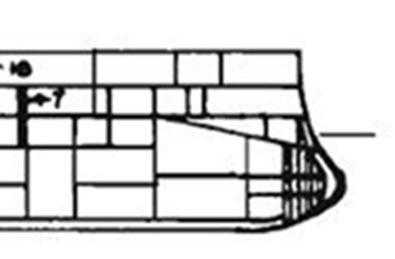
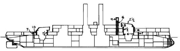
Ok. Better late than never... I took another look in the magazine and I think the mystery is hidden in the lines below. Some additional web search, confirmed the construction and the use of a ram for the pre-dreadnoughts and a closer look at the previous drawing, shows the plates over many bulkheads at the bow. Finally we can end up that those iron plates were supporting the ram. Thanks

- 116 replies
-
- 1
-
-
- kilkis
- mississippi
- (and 2 more)
-
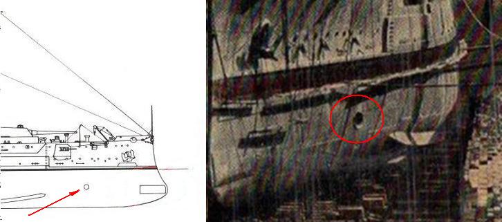
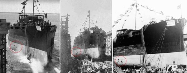
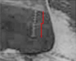
Mark, the two torpedo tubes that fire abeam, were no affecting the hydrodynamic state of the ship. Maybe that's why there were no doors-shutters, at least being shown. I don’t know what you have seen as moving side back-up and down doors but you have to consider the position of the arm-s that was holding-removing the plate (shutter) and the channel on the surface of the hull, inside which had to be moving (the arm-s). The book says that the two abeam tubes were the only ones since of her build. There is also a drawing which I can’t “read” it... and a photo from her construction but I don't think it shows something more. ... In my research I have found two more photos from her launching and after some Photoshop work, maybe there is something interesting on one of these. As you can see the marks of the draft appear to follow a step at the hull’s surface and maybe this is an indication that the plates were placed from the beginning of her construction. Unfortunately I don’t have more information on this and yes I have already proceeded as if they are iron plates. Thanks
-
Hi all and thank you for your answers. Well, I'm not an expert but here are some thoughts of mine. If we consider them as shutters of the torpedo tubes, then, as far I know those shutters are withdrawn inside the nest of the muzzle at the side of the vessel (in a submarine). But in this case these "shutters" look rather like closures-covers and I can't imagine how these would be functional (for them themselves or the ship) being expanding away from the hull, in ship’s battle speed. In the other hand, I don’t think you construct torpedo tubes and seal them, just because you change your mind …or you construct them for a potential future use… You don't make torpedo room-tubes without plans. Plans are needed because it's not only the outer doors of the tubes. You have to draw also the surrounding area and how this battle station is going to be fitted in the specific part of the hull. There is also the matter of the ammo. You have to draw the whole path through (the rest apartments) a torpedo will end up at the launching room (or the store room) when the ship replenishes ammo. Therefore I think it's not so easy to abandon or modify a construction at that scale and when this already has been made. Of course “There is always a first time for everything”… So until a new valid point of view, I tend to believe that are iron plates to provide protection or reinforcement to the bow. Thanks

-
Bilge keels are set, eight (8) of them...! I will proceed with the plates at the bow... the question can wait. Thanks
- 116 replies
-
- 4
-
-
- kilkis
- mississippi
- (and 2 more)
-
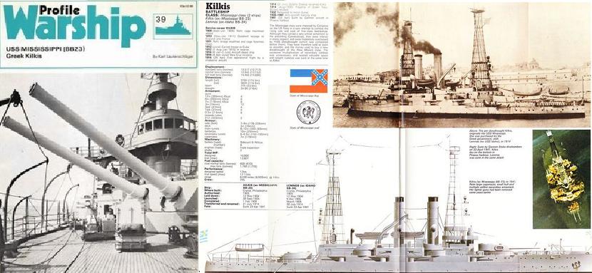
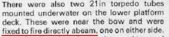
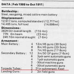
Thanks for the answer John. This was also my first thought but in the magazine (Warship profile No 39) is written that: “There were also two 21in torpedo tubes mounted underwater on the lower platform deck. These were near the bow and were fixed to fire directly abeam, one on either side.” So, it must be something else (?) Thanks
- 116 replies
-
- 2
-
-
- kilkis
- mississippi
- (and 2 more)
-
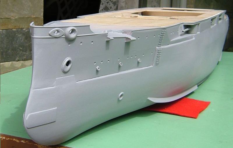
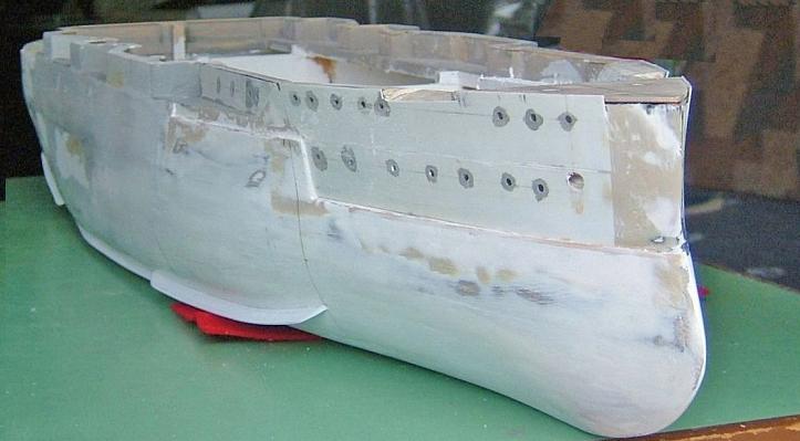
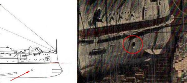
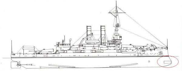
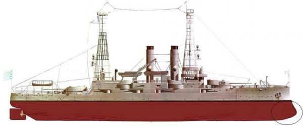
Hi. I’m doing some work at the ship’s hull, actually I’m constructing some bilge keels (there are many...). So studying drawings and photos, I came to a query. As you can see there is a metal plate at the bow, (I guess both sides) in which I didn't manage to find any information. Is there anyone who can enlighten me? Thanks
-
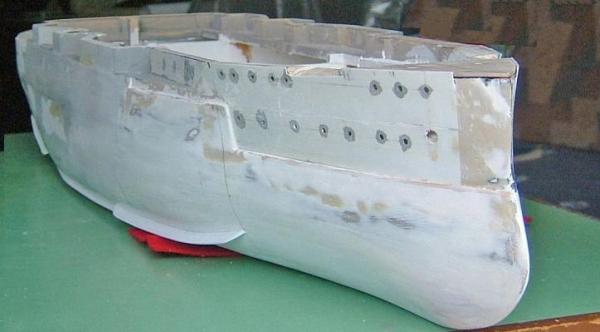
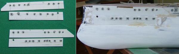
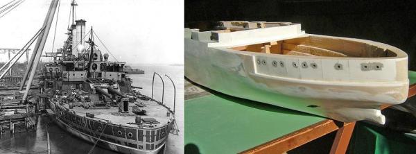
The work with those plastic strips… The strips at the prow were cut in the proper shape, the portholes were opened and they painted with gray color in their thickness. I made the painting at this stage, because later it would be quite difficult without spoiling the black background… Coming to stern the work was a bit different. If I was going with a strip in one piece (for each side) this should be curved in both axes and that wasn't easy. Watching a photo showing the real ship in repair stage, I noticed that there were iron plates that were forming - covering the same part of the hull. And that was what I needed... Thanks
- 116 replies
-
- 3
-
-
- kilkis
- mississippi
- (and 2 more)
-
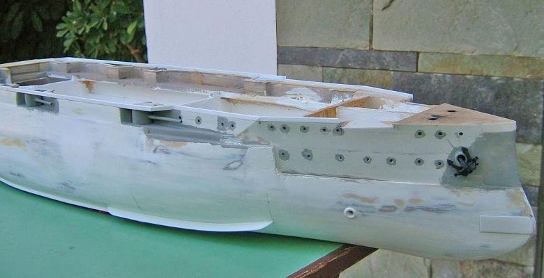
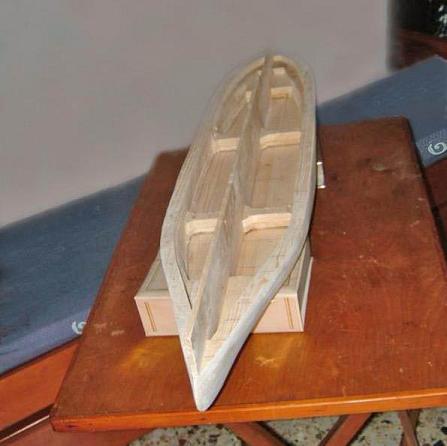
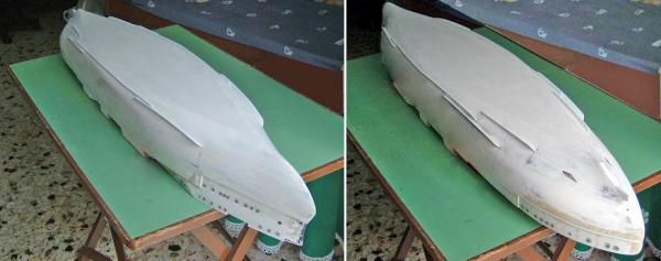
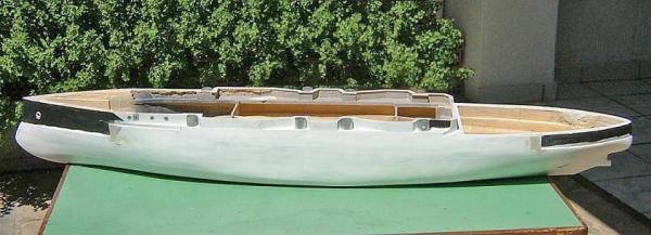
The construction goes slow but steady… The waved construction in the middle of the hull has been set as well the turrets of the eight (8) ( 7'' ) side guns. The turrets have been made by cutting an aluminum tube but for the time being without barrels, as they are going to be built later. Avoiding photos from the joyless stage of grouting, filing, making dirt and dust, I'm just posting a photo of the hull, in the middle of that process... The black painted parts are going to be covered by properly shaped plastic strips. On these strips, I will shape portholes and thus the black color will give the sense of the inner of the hull. Wait for my next post... Thanks
- 116 replies
-
- 5
-
-
- kilkis
- mississippi
- (and 2 more)
-
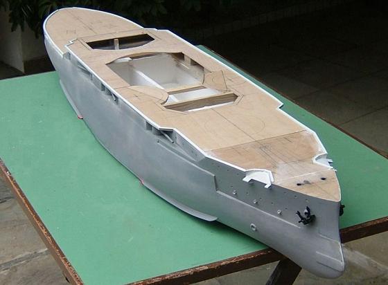
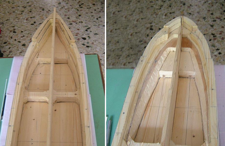
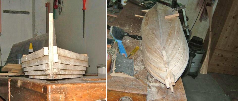
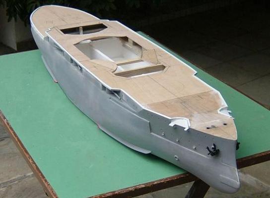
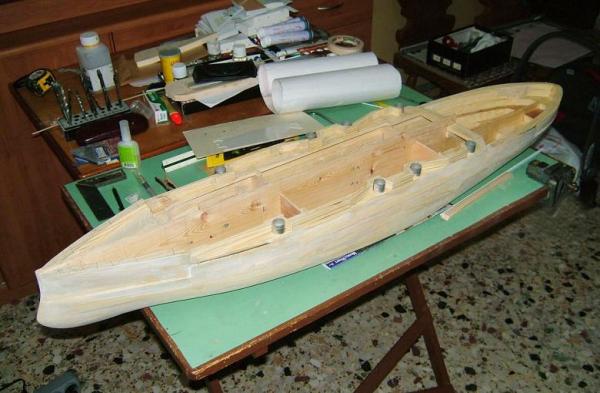
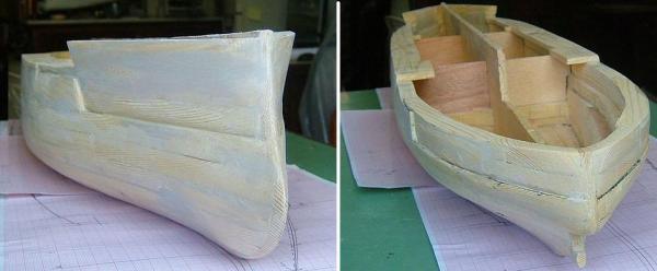
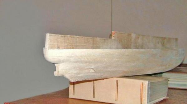
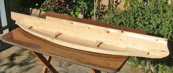
Some more progress, raising up the bow and the stern… I was trying to save some wood, using small spare pieces of it, but soon I realized that it was a waste of time, trying to adjust them properly in places… At this point I have reached the level of the deck for the prow and stern. The deck at the middle of the hull will be supported by a waved construction, leaving also room for the eight (8) ( 7'' ) side guns. Pencil marks at the positions of the side guns. Thanks

- 116 replies
-
- 4
-
-
- kilkis
- mississippi
- (and 2 more)
-
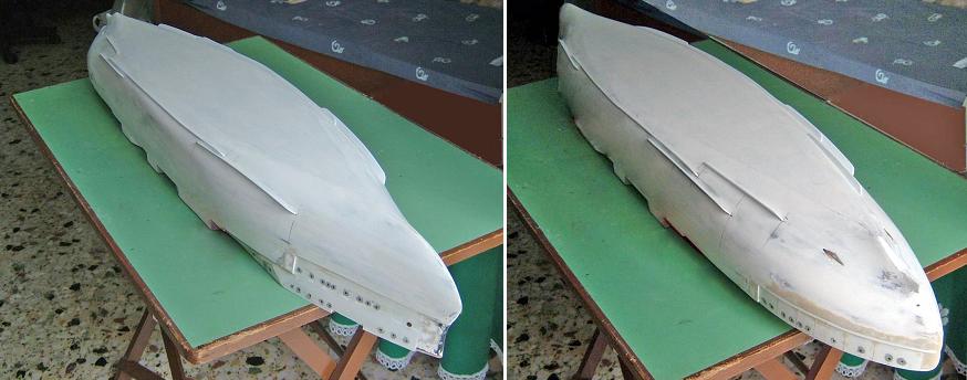
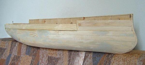
Some progress. The hard work... The result ...................... Thanks


- 116 replies
-
- 2
-
-
- kilkis
- mississippi
- (and 2 more)
-
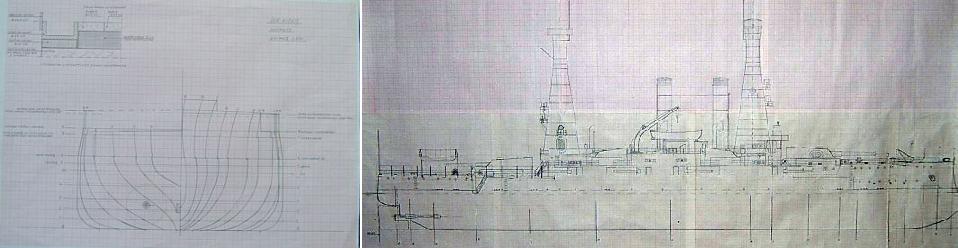
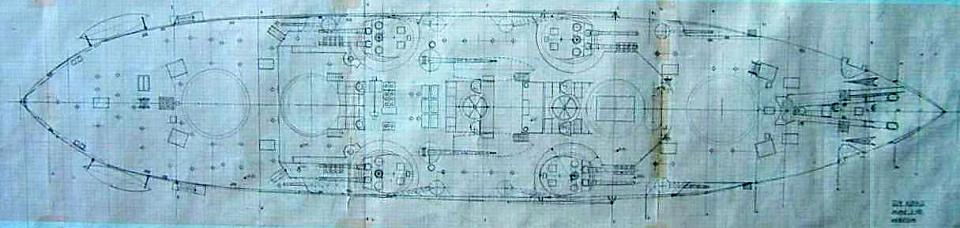
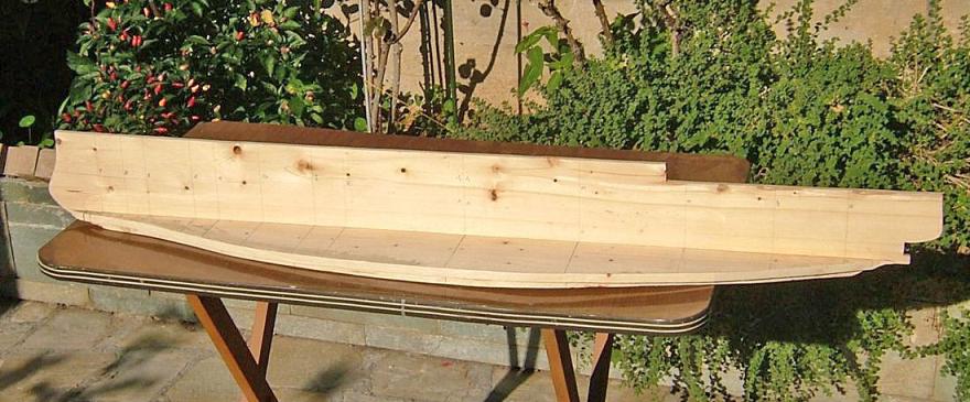
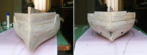
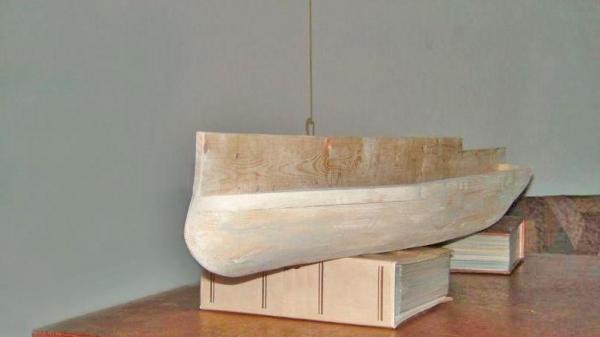
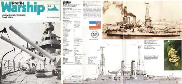
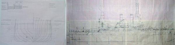
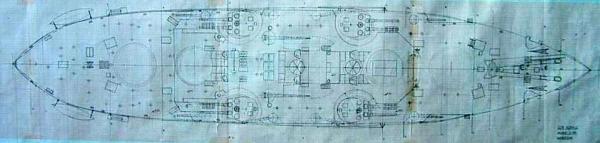
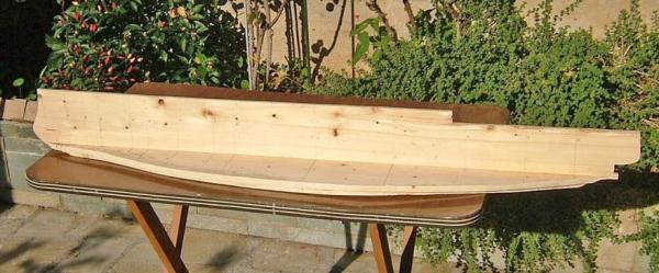
Thank you mates.... Having decided to go with “Kilkis”, I started gathering information from wherever I could find them. Again my Greek friend Falieros (an acclaimed modeler), from his personal collection, provided me some incomplete drawings, which along with information and photos from the magazine “Warship Profile no 39", gave me what I needed to re-draw the hull lines. I chose to build the model in the scale of 1:100, not only because this is my favorite scale, but also because at this scale, the model will reach the 116 cm (45.6693 inc) very convenient length, that will allow me to carry it easily it in my cars’ back seat… For those who are not familiar it's a big torment when you have to carry such a model in a trailer or on the roof of a car... So for one more reason I felt happy... I proceed with the “bread and butter” method and the first planks are set. A difference from the previous models of mine is that in the middle of the first planks, I placed a vertical plank shaped as the side view of the hull. By doing this, I have a guidance but also a support, when I’ll be placing the rest of the horizontal planks, shaping the hull. Thanks

- 116 replies
-
- 6
-
-
- kilkis
- mississippi
- (and 2 more)
-
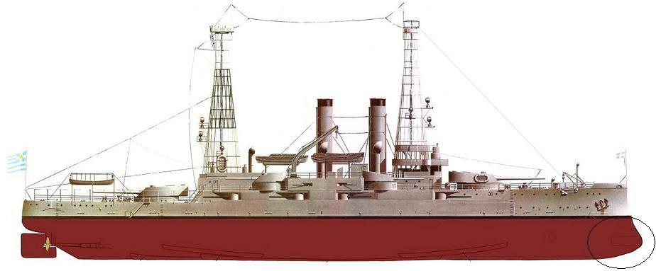
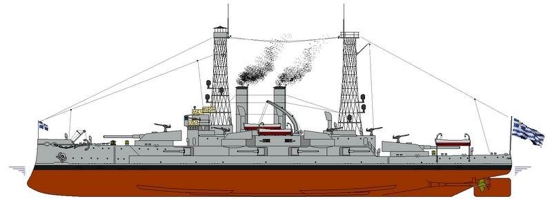
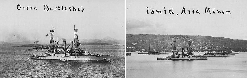
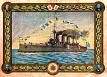
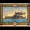
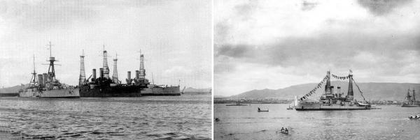
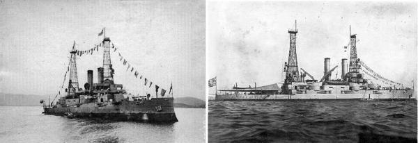
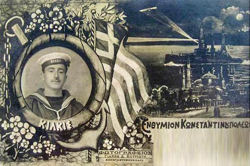
Hi all. After the construction of the model of Armed Cruiser Averof and a time of laziness, I decided to start a new model. This time it’s the Battle Ship “Kilkis”, another warship of the Greek Navy. Kilkis (Greek: Κιλκίς) was a 13,000 ton Mississippi-class battleship originally built by the US Navy in 1904–1908. As “Mississippi bb-23” she was purchased by the Greek Navy in 1914, along with her sister “Idaho bb-24” and they both renamed as “Kilkis”, and “Lemnos”. Kilkis was named for the Battle of Kilkis-Lahanas, (an aria nearby the town of “Kilkis” at northern Greece) a crucial engagement of the Second Balkan War. She was armed with a main battery of four 12 in (305 mm) guns, Kilkis and it was the most powerful vessel in the Greek fleet. (along with her sister “Lemnos”) The ship saw limited action during World War I. as it was decided to be operated solely as a harbor defense ship. In the immediately ensuing Greco-Turkish War of 1919–1922, “Kilkis” supported the Greek landing in Asia Minor and participated in the final Greek sea-borne withdrawal in 1922. She remained in service into the early 1930s, when she was used for a training ship. During the German invasion of Greece in 1941, she and her sister were sunk in Salamis by German Ju 87 Stuka dive-bombers. The two ships were ultimately raised in the 1950s and broken up for scrap. More of its history http://en.wikipedia.org/wiki/Greek_battleship_Kilkis Below I post some photos of her Greek carrier. Thanks ......................... ......................... ......................... ......................... ....................................

- 116 replies
-
- 2
-
-
- kilkis
- mississippi
- (and 2 more)