

Jeronimo
-
Posts
716 -
Joined
-
Last visited
Reputation Activity
-

 Jeronimo reacted to EdT in HMS Naiad 1797 by EdT - FINISHED - 1:60 - 38-gun frigate
1:60 HMS Naiad 1797
Part 117 –Upper Deck – Ironwork, Scuppers, Riders
Posted 1/23/12
This week all the inboard planking of the upper deck was completed on the port side. I haven’t made a decision on the stuff between the ports on the starboard side yet, so work continued on the port side. The first picture shows some ironwork on one of the ports.
The tackle eyebolt on the forward side of this port is not yet installed, nor is training eyebolt forward of the ringbolt, but the hole is ready for it. The two spirketing bolts through the through the sill can be seen.
The next picture shows some more of this in the area of the captain’s cabins.
There was no fancy side paneling in the cabin area but the inboard planking was supposed to be planed smooth. The carlings for the half beams and the half beams themselves are not installed yet.
The next picture shows the area at the forward end on the waist.
Some eyebolts are still missing. Two of the scuppers can be seen in this picture. The next picture shows more of this side.
All the top riders on the port side have been fit up to the planking and reinstalled. More of the scuppers are visible in this picture.
The next picture shows some of the scuppers on the external starboard side.
On each side there are several 4” scuppers for general deck drainage and two larger 5” scuppers – one for the pump discharge and one all the way forward to drain the manger. These were fashioned from copper tubing to simulate the lead flanges at each end of the pipe. They next picture shows the detail on the unplanked exterior port side.
The copper tubing was fit into square stock and then notched into scores between the frames. Inside and outside parts were made separately. Since the exposed port side has not been final sanded at this stage the scuppers have not been blackened yet.
The last picture shows current progress looking aft.
Ed
-
Jeronimo reacted to EdT in HMS Naiad 1797 by EdT - FINISHED - 1:60 - 38-gun frigate
1:60 HMS Naiad 1797
Part 116 –Upper Deck – Quickwork
Posted 1/17/12
The first picture shows some of the last work on the upper deck spirketing installation at the bow.
The piece on the port side is being glued – held in place by pins. The piece on the starboard side was boiled and clamped to set the bend. In this picture it has dried and is ready to be unclamped, sanded and glued in place.
The next picture shows work on the stuff between the ports. This work proceeded concurrently.
This thinner planking is Castello, to give some contrast with the pear spirketing and the quarterdeck clamps. The three strakes are pinned in place for gluing. Only the port side will get this planking.
I’m trying to keep up on the outside of the hull. The next picture shows some work done concurrently with the inside work.
In this picture the upper deck lodging knee bolts have been installed in a long fair line on the outside of the frames. Most of the hanging knee bolts were installed earlier. Also, the holes for the spirketing bolts through the sills and the bolt holes for the gun tackle ironwork have been drilled on both sides of the ports – all the way through from the inside.
The next picture shows a test of one of the ringbolts on the inside.
The eyebolt has an inside diameter of 2” and ring 4 1/2'”. These will be inserted halfway through the hole and glued with CA. These are blackened copper. Monofilament will be used to simulate the outside of these bolts.
The next picture shows the first group of these fittings installed.
The sequence here was to install the treenails, fully sand the planking, fit and re-install the topriders, then install the ironwork. I am doing this one section at a time, working forward – to break up the monotony of treenailing. This picture also gives a good view of the two spirketing bolts through the sill.
The next picture shows the area of the upper deck finished so far.
And the next picture shows the work forward of this – the treenailing.
These have yet to be leveled off and sanded. In doing these I have to remember which holes will get bolts and leave out the nails. I’ve had to redrill a few so far. In this picture the waterway has been cut to receive the riders. Also note the step up from the end of the quarterdeck clamp to the string in the waist, just where the Qdeck ends.
A few more days work should see the end of the inboard planking on this deck.
Ed
-
Jeronimo reacted to EdT in HMS Naiad 1797 by EdT - FINISHED - 1:60 - 38-gun frigate
1:60 HMS Naiad 1797
Part 115 –Upper Deck Waterways, Spirketing
Posted 1/10/12
After the last posting, all of the remaining ledges of the upper deck were installed. The framing of the deck was then leveled out where needed and the filling pieces at the side were pared down level with the tops of the deck beams. The next step was to install the waterways. In the next picture stock is being shaped to make these.
The waterway is thicker under the first strake of spirketing, tapering down in a curve to the thickness of the deck planking. The machining of this shape was done in two steps. First the concave curve was cut with a round ended milling cutter. Then the second cut was made to level the end that would abut the deck planks. The simple jig in the picture was made to guide the pieces through the cutter.
The next picture shows one of the forward, curved pieces of waterway being fit.
The flat piece of Castello was shaped to fit the curve of the frames using a disk sander. For curved pieces like this I do not bother with card forms or spiling. The shape was roughly drawn on a rectangular piece of wood and then progressively sanded to shape until a tight fit was obtained. The width of the piece was the marked with a small compass, cut on the scroll saw, then sanded to shape. A different jig was used to machine these curved pieces.
The next picture shows the waterways installed.
This picture also shows the installation of all the ledges. On the starboard side, the joints are cut, but the actual ledges are left out for visibility into the lower decks on that side.
Next is another picture taken further aft.
The top riders were all removed before installing the waterways. The waterways will have to be cut out to permit these to be installed later. This seemed easier than trying to fit the waterways and the rest of the interior planking behind the riders.
Before moving to the spirketing, the port gunport linings had to be installed. The next picture shows a couple of these after the linings were faired down with 120-grit paper.
There is a bit of lens distortion here which makes the line of these last three ports appear humped. The outside of these port frames will be finish sanded later, since they will be left exposed. The notches in the frames below the ports are the openings for the lower deck scuttles.
The next picture shows the spirketing on the port side mostly installed.
This comes up to the tops of the port sills and its upper edge is dubbed off to be horizontal at the height of the linings. The large block is holding one of the guy wires that keep the hull in place. These were removed to work on this in that area, then replaced.
The next picture is a closer view of the aft sections of spirketing being installed on the starboard side.
The spirketing on the lower deck is installed with anchor stock configuration. This was spelled out specifically in the three contracts from the Naiad period that I am using. This was not specified in any of those for the upper deck, so these are being installed as straight planks. The pins are forced through slightly undersized hole using pliers to hold them in place when gluing. The tops of the planks were dubbed off using a Stanley number 93 plane with the stock held in a wide vise.
The last picture shows the run of spirketing on the port side, pinned and glued in place.
While these pictures were being taken, the curved section at the bow was being clamped to shape in place after boiling.
The next step will be to plank between the ports on the port side only. The top riders can then be reinstalled.
Ed
-
Jeronimo reacted to EdT in HMS Naiad 1797 by EdT - FINISHED - 1:60 - 38-gun frigate
1:60 HMS Naiad 1797
Part 114 –Upper Deck Main Partners
Posted 12/31/11
In the last post the central beam and beam arms were installed. The next step was to fit the main mast partners, the main hatchway carlings and hatchway details. The first picture shows this area.
The hatchway coamings and headledges for the main hatch and main companionway, including the steps, are installed in this picture. Also, the cross chocks of the partners are set into the rabbets in the large sized partner carlings, which are fitted but not glued. At this stage only the fore and aft chocks are glued to to the carlings to allow the assembly to be removed to the bench for detailing. The cross chocks around the pump casing have been cut to fit but are loose at this stage.
The next picture shows the assembly removed for further work.
In this picture the central cross chock and fillers on the sides of the openings have been glued in. The outline of the corner chocks has been marked out and one of these is set over its location so the rabbet lines for it can be marked. Rabbets were then let down and the cross chocks inserted. These are made in two parts, top and bottom, to avoid having to cut rabbets in these very small pieces.
The finished assembly is shown below.
The cross chock section just aft of the openings for the pump casings is still loose in this picture, to allow the assembly to fit over the casings. In the next picture the installation is complete.
The four Cole pump casings are now permanently glued on to pins in the well and all the sections of the cross chocks and the whole assembly is glued in. The two elm tree pump casings, for some reason are too short, so these will be replaced. The two pump carlings, outside of the partners, are also installed in this picture.
The next picture shows some preparatory work being done to get ready for the pump cisterns.
In this picture the cross piece of boxwood has been fitted around the pump casings. This will then be slit into two pieces that will then be edge glued to form the floors of the two cisterns.
The next picture shows the two pieces joined and fit over the casings.
The blank for the cistern floors has been made in one piece to help assure that the two cisterns are precisely aligned and not affected by misalignment of the four casings or due to differences in the cutouts. The next step will be to rip this piece down to the bottom width of the cisterns then separate it into the two separate floors. I do not expect the cisterns to be watertight.
The last picture shows the state of the upper deck on the last day before New Years eve 2011.
The thread on the centerline has been a big help in keeping things centered on this deck. All the upper deck carlings are installed at this stage. The long strips of Castello lying on the deck are blanks for the waterways. These will be milled and installed on both sides as was done on the lower deck. The inside planking of the port side can then begin.
Happy New Year everyone.
Ed
-
Jeronimo reacted to EdT in HMS Naiad 1797 by EdT - FINISHED - 1:60 - 38-gun frigate
1:60 HMS Naiad 1797
Part 113 – The Last Upper Deck Beam
Posted 12/19/11
The last beam was the most complex and most interesting to install, but first two pictures on the lower deck – the last opportunity to put the little camera into the gap between beams.
Depth of field isn’t great, of course. This is looking aft on the lower deck, giving a nice view of the wing transom knee, sleepers and sternson knee. The rope is waiting to be threaded up through the wheel and back through the tiller sweep.
Port side looking forward. The small forest of pillars to the right, between the bitt pins, supports the fireplace.
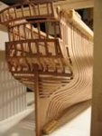
Finally, the last beam.
This beam, number 16, is just aft of the main hatch and just forward of the main mast partners, so it is quite a distance from its two neighbors (Beam 15 is still out in this picture.) The beam is reinforced with two sets of beam arms just like its lower deck counterpart. The beam could not be prefabricated with its arms. The problem is illustrated in the picture. Getting this beam in even by itself required some deflection because of the tapering in of the sides. There was no way it could be set with even one of the arms attached – well, maybe one.
There are a variety of wood and iron knees used in this assembly and they will be described below. We do not know exactly how these were done on the actual Naiad, so the mix is speculative. Getting a workable sequence for fitting all these knees and assembling the beam in place was an interesting problem.
The first step was to make the beam arms and the tabled scarphs to the main beam. The picture below shows the basic pieces.
After cutting the basic shapes of the arms, the scarphs were marked out while the pieces were fit in place on the model – not from this drawing. The scarph tables were all cut manually. One of the steps is shown in the next picture.
The joint lines were first cut with a razor saw, then pared out with the chisel, then dressed with a file. I could have done these on the mill, but this way is easy and avoids set up on the mill
In the next picture, wood hanging knees are being glued to the ends of the beam.
The beam is pinned but not glued. It was then removed to level the tops of the knees and install the hanging knee bolts through the beam. It was then permanently glued in and its pillar installed. The lodging knees for this beam are iron and will be shown later.
The beam arms were then pinned in place so the mortises for the carlings could be marked out as shown in the next picture.
A long strip of carling stock is being used to mark the mortises and assure the overall line of carlings is straight. The mortises will then be chiseled out on the bench.
The next picture shows the wood lodging knees on the forward arms being glued to the arms.
The arms are only pinned in this picture. The hanging knees for these forward arms are iron.
The next picture shows an iron lodging knee for the main beam being installed.
The iron (copper) knee is clamped to the beam. The hole for the first bolt has been drilled and the bolt is being forced to the bottom of the hole with pliers in this picture. It will then be cut off above the surface of the knee and hammered in, expanding the head. The other bolts will then be installed including one into the frames. The fore and aft arm of this knee is short because there is a rider to be installed just forward of the beam.
The next picture shows an aft arm assembly about to be installed.
This arm (upside down) has two iron knees that have just been blackened after bolting. The wood is still wet from the sulfur solution being washed off.
The next picture shows a beam arm on the port side being glued in place.
These were done one at a time with their knees installed. With both arms permanently fixed, the bolts through the beam were installed through holes drilled earlier. Bolts were then also installed in all the iron knees. Holes were predrilled for these while the pieces were still removable.
The last picture shows the completed beam installation.
The outer tiers of carlings, except for one piece, have been installed in this picture. All the upper deck beams are now installed.
Time to take a Christmas break and ponder the next move.
Best wishes to all for the holidays!
Ed
-
Jeronimo reacted to EdT in HMS Naiad 1797 by EdT - FINISHED - 1:60 - 38-gun frigate
1:60 HMS Naiad 1797
Part 112 - Upper Deck Beams – Hatchways
Posted 12/2/11
Work continued this week on the upper deck beam installation, which is now becoming routine – fit the beam, make and fit the wood knees or chocks, bolt on the iron knees, set the beam install the pillar, then the hammock battens and then the carlings. The first picture shows beam 9 installed, the first beam aft of the main bitt pins.
The next four beams, 10 to 13, are temporarily positioned with the filling pieces between them installed at the sides. The next picture shows beams 10 to 12 installed.
I have been installing the carlings and in some cases the ledges with the beams, partly to break up some of the monotony but also to allow some of the between deck structures to be installed, like the ladderway aft of the fore hatch shown in this picture.
The next picture shows beam13 installed and the next two laid in place.
Beam 13 has wooden hanging and lodging knees – a small change of pace. A further diversion this week was the installation of some of the coamings and head ledges for the hatchways as shown in the last two pictures.
These coamings and head ledges rise 13” above the deck at this level. To do that they need to be 16” high, considering that the deck planking is 3” thick. The coamings are rabbeted for the grating ledges and the corners are made with locked lap joints. The sides are bearded at the top 1” and the corners will be rounded above the level of the deck. The intermediate cross pieces are set in scores on the coamings. All these will be bolted to the beams.
The next picture shows the hatchways further aft.
The single large opening to the right is the aft hatch, which, like the fore and main hatches, goes all the way down into the hold. The double hatchway to the left will have a ladderway in the forward opening. The aft opening is a hatch only to the lower deck. The step for the capstan will cover the opening just ahead of this hatchway structure.
Ed
-
Jeronimo reacted to EdT in HMS Naiad 1797 by EdT - FINISHED - 1:60 - 38-gun frigate
1:60 HMS Naiad 1797
Part 111 - Upper Deck Beams – Riding Bitts
Posted 12/2/11
After the last post there were some questions about the hammock battens. The first picture shows how they were milled on a wide piece before being slit off on the circular saw.
This piece is about 6“ thick allowing for a 3” square batten with three inch blocks to offset it from the beam. A 3/16 inch square end mill was used and advanced ¼ inch after each pass. Two of these pieces were needed. The next picture shows how the sliced off battens were fastened.
I found that these were easier to glue on and clamp after the beams were installed. They are flush with the bottom of the beams and held with clamps after gluing.
After the first four forward beams were installed the riding bitts had to be addressed with the next set of beams. The first step was to install the forward bit pins against the aft side of beam 4 and the same beam on the deck below. The main issue with these is that they be equidistant from the centerline and vertical. The thread line seen in most of these pictures was used constantly. The next picture shows the forward pins and their standard knees installed.
The knees of these forward pins form the sides of the rabbet for the cross chocks that make up the mast partners. The carlings under these form the supports under these chocks. The rest of the mast partners assembly will be installed later.
The next picture shows a top view of this with Beam 5 installed.
Beam 5 has plain iron knees because of its proximity to the first ridersnotshown), which leave no room for the tabs on the plate knees. Beams 5, 6, and 7 have double pillars supporting their centers. These beams supported the galley stove and its heavy layer of refractory brick or stone, which was used to insulate the wood structure from the hot stove fireboxes. It was probably important that this structure be very rigid to keep the brickwork from breaking up as it flexed.
The next picture shows a beam being “jacked up” or “sprung” so it can be popped into place.
If the beams are cut to just fit between the frames, this bending is necessary on this deck because the tumblehome of the sides prevents the beam from fitting above its notch in the clamp. Having the beams fit tightly, apart from the aesthetics, is a good idea because it makes marking out the centerlines and carlings more accurate and helps maintain straight lines. This beam had the hammock battens installed on the bench, but with this heavy handling it is easy to break them – one of the reasons I later decided to wait for the beams to be installed before adding these..
The next picture shows beams 5 and 6 installed.
In this picture the wider carlings under the bit standards are also being installed along with each beam. I made these flush with the beam tops like the other carlings, In practice the bitt standards were let down 1 to 1 ¼” on the beams, which would require the carlings to be lower by that amount and the ledges to sit above the tops of the carlings by that amount. These .02” scores will be barely discernible on this deck so I took the simpler approach.
The next picture shows the carling under the fireplace – another interesting bit of construction.
This long 9” square carling is scored and let up about 2 “ on the underside of the beams. The space between the top of this and the undersides of the ledges was filled with fir filling pieces. In the picture the fillers and the ledges are installed in the forward two spaces. In the third space only the filler has been installed with the ledge still lying loose. The fourth space has no filling piece as yet.
Beam 8 is securely fastened to the aft bit pins with two bolts. It is also fitted with wood hanging and lodging knees. The beam was installed first with the ends fastened securely with its knees and bolts. The starboard bit pin was almost perfectly positioned, but its partner was leaning a bit to the center. The starboard pin was then glued and bolted to the beam. When this was secure the port pin was then forced slightly to the side to make it right, wedged in place at the beam score, glued, clamped and bolted. The deflection was slight but the small misalignment was very noticeable.
The next picture shows the aft bitt standards after installation.
These are bolted through the beams and through the wide carlings below. This picture also shows three pillars under the fireplace carling for additional support. This final structure should have no problem supporting my model stove, no matter what it is finally made of.
The last picture shows the overall model at this stage and the amount of upper deck structure remaining to be installed.
The work from this point going aft is pretty straightforward up to the last remaining beam with its two curved beam arms.
All of the remaining plate knees have been etched out. The first few were .005” thick, but all the subsequent ones are made from .01” copper. They do not look much different but they are a bit more resistant to handling damage when the beam assembly is being taken in and out..
Ed
-
Jeronimo reacted to EdT in HMS Naiad 1797 by EdT - FINISHED - 1:60 - 38-gun frigate
1:60 HMS Naiad 1797
Part 110 - Forward Upper Deck Beams
Posted 11/21/11
After installing the aft upper deck beams as far as midship, I moved to the beams in the bow so that beams are being installed smaller beams first. This facilitates the maneuvering of succeeding beams into place and also the installation of the lodging knees, which were always on the midship facing side of the beam.
The first piece to be made in the bow was the upper deck hook. This was cut and fit against the hawse timbers then removed so it’s assembly with beam #1, the ekeing pieces and the beam’s hanging knees, carlings and ledges could all be done on the bench. The first picture shows the finished assembly.
Beam #1 has wood hanging knees and angled iron lodging knees. The next picture shows the installed assembly.
You will notice in this picture that the forecastle clamp has been sawn through in four places because I forgot to cut the air gaps between hawse timbers before installing these clamps. This piece and the same piece on the port side will be replaced.
The next picture shows the iron lodging knee on the starboard side of beam #1 being bolted into place.
After marking and drilling undersized holes in the beam, the drawn copper wire is being forced to bottom in the hole with pliers. It will the be clipped off just above the surface and peened over with a hammer. The next picture is a scary closeup of the finished knee taken right after chemical treatment.
That’s a three-penny finishing nail at the bottom of the picture holding a copper guy wire. The picture also shows a black monofilament bolt that has gone astray and missed the beam. Isn’t magnification great?
In the next picture beam 2 is installed and beams 3 and 4 are being fit up.
The next picture shows the first two beams with their carlings and hammock battens installed.
These battens provide spaces for hammocks to be hung on the prescribed 14” centers. Hammocks would have been slung between battens on every other beam. The battens on the aft side of beam 2 will pair up with those on the fore side of beam 4. Most beams will have battens on both sides, but not those at the ends. These forward hammocks would probably have been in the sick bay. There will be about 250 hammock spaces on this deck. Everyone slept on this deck except the captain and the few junior officers with spaces on the platform below at the orlop level. Things on this deck were a bit tight to say the least.
The last picture shows the extent of upper deck beams installed so far.
Time to photo-etch some more plate knees.
Ed
-
Jeronimo reacted to AnobiumPunctatum in HMS Naiad 1797 by EdT - FINISHED - 1:60 - 38-gun frigate
Ed,
it's allways a pleasure to follow the build of your masterpiece. Many thanks for redoing your build log. It is a great help for me.
-
Jeronimo reacted to EdT in HMS Naiad 1797 by EdT - FINISHED - 1:60 - 38-gun frigate
1:60 HMS Naiad 1797
Part 109 Upper Deck Beam #17
Posted 11/17/11
Up to this point the beams from #29 forward to #17 were fitted with angled iron knees to leave the officers some room in their tiny cabins. Beam #17, the first to be clear this area is being modeled with Roberts style plate knees, one on each side of each beam end. The simple chocks used between these plate knees did not require compass timber and that was a key reason to move to iron. The next beam forward, #16, with its beam arms, will be the last to be installed, so after #17 the work will move to the bow area.
The Roberts type plate knees were made by photo-etching sheets of .005” copper. The third attempt at etching is shown in the next photo.
Photo-etching is, to say the least an interesting and intricate process. I think it will take some practice to get 100% yields, but this third attempt produced 12 out of 14 good knees. In the first attempt the holes came out too big so the size had to be reduced on the “artwork.” The entire photo resist was lost on one side on the second attempt due to poor laminating. I won’t go further into this process except to say there are a lot of steps and some nasty chemicals involved.
The next picture shows one of the chocks being pinned and glued to the beam.
With the beam in place the chock was held against the side and the pinhole drilled. It was then glued on as shown above. After this gluing step, two copper bolts were CA glued through the beam from the top to hold it together securely. The chocks were then tapered. They are somewhat narrower at the bottom and flush with the beam sides at the top.
The next picture shows the plate and all the bolting installed on one end.
In practice these plates were set into the wood, but I wasn’t up for that task. The bolts went all the way through both plates and the chock. The model bolts in the plate are really nails. A piece of wire like the one in the picture was forced into a tight hole with pliers, clipped off close to the surface and peened over with a hammer. The extended tabs at the end of the beam will be bent over to bolt into the filling pieces and frames. The black bolts through the chock into the frames are black fishing leader.
The next picture shows the whole beam assembly.
The next picture shows the assembly fit into place for the marking of the holes in the filling pieces.
The filling piece shown is loose and has not yet been cut to size. The next picture shows this connection, after blackening the knees and gluing the beam into place.
The bolts in the tabs can now be installed. The filling pieces will be dubbed back to the beam height later before installing the waterway.
The next picture shows the beam completely installed, with its pillar (not visible) and carlings.
The picture also shows the pump shafts, which need to be detailed and maybe installed before the upper deck framing is done in this area. The four square Cole pump casings have had their clamping brackets installed at this stage – ebony plates with long wire fastenings. The bent wire staples in the top maintain the distance between casings at the top of each pump. The lower deck structure, decking and partitions have been given a coat of finish up to this point.
The work will now move to the upper deck beams in the bow area so it can continue in a sequence from smaller to larger sized beams finishing up with the beam just forward of the main mast and its arms.
Ed
-
Jeronimo reacted to EdT in HMS Naiad 1797 by EdT - FINISHED - 1:60 - 38-gun frigate
1:60 HMS Naiad 1797
Part 108 Upper Deck Beams, Continued
Posted 11/14/11
The upper deck beams continue to march forward – one beam, two filling pieces, four iron knees, 32 bolts, a pillar and four or so carlings at a time – plus some partitions. The first picture shows the first additional beam added since the last part.
The next picture shows the ironwork on the other side of this beam.
The hanging knee in this picture is canted slightly to get the two lower bolts into the next frame forward of the one holding the standard knee bolts. The boltholes on the lodging knee were drilled to go into a frame. This knee has a short horizontal leg due to the closeness of the next beam forward.
There are a lot of partitions on the aft end of this deck and they have been installed progressively with the beams. If these were installed before the beams it would be impossible to drive in the bolts or peen over the bolt heads on the knees. Drilling the holes and installing these bolts is a challenge even without the partitions. Most of the holes into the frames are being drilled with a Dremel tool with a right angle head attachment.
The next picture shows some of the partition work in progress.
Partitions and doors were prefabricated to fit before the beams were in place, then installed after the beams. This picture shows the pre-made double paneled doors to the ward room and one of the dividers between the officers’ cabins before being installed. The long wall with the officers’ cabin doors is not shown in this picture. It was made early on in one piece but could not be fit until all of the overhead beams were in.
The next picture shows that wall installed and also the slanted wall with double doors dividing off the ward room – of if you prefer the officers mess, or my preference, and Patrick O’Brien’s, the gun room.
The door hardware in this area was simply made using small ebony bits. This allowed all these very small pieces to be glued with Titebond rather than the messier CA - had blackened copper been used
The next picture is from a different angle and shows all the beams and partitions as currently installed.
The double, paneled gun room doors can be seen just above the right center of this picture. Just below the center on the centerline is the Captain’s pantry with one paneled door, a storage bin and some shelves.
Partitions are only being installed on the port side, which will be partially planked. The starboard side is all about structure.
The next picture is a closer view of one half of the Captain’s pantry.
The thread running along the centerline is being used to constantly check alignment - more on this below.
The next picture is a close up of the three cabin doors within the gun room area. The tiller rope and sheave can be seen to the left.
I have not included much on the need for alignment as the decks progress upward. I have shown wire and thread lines in some past photos. This alignment requires constant attention. The centerline is one important reference but the upper framing needs attention as well, as beams are tightly fit within the frames at each level. The next picture shows what I have been doing to keep the frames equidistant from the centerline on both sides.
These plywood templates were made from the top part of the frame patterns for every fifth station or so. Since they include a centerline it is easy to check that this line matches the center string line when the patterns are fit over the sides. As internal and external planking gets added the slots on each side need to be opened up so the template will fit. These are being used periodically when the beams or other structural parts are being fit up.
The area just completed has involved the most complex installation sequence so far – largely because of the problems getting the bolts in – and some preplanning was well worth it..
With the last of the beams over the officers’ cabins installed, most of the remaining knees will be of a different type. For the most part these will be Roberts plate knees. I am expecting to make these by photo-etching copper sheet. Perhaps some of that will be done by the next part.
Ed
-
Jeronimo reacted to EdT in HMS Naiad 1797 by EdT - FINISHED - 1:60 - 38-gun frigate
1:60 HMS Naiad 1797
Part 107 Upper Deck Beams Continued
Posted 11/5/11
The work on the beams of the aft part of the upper deck continued. These beams are over the officers’ cabins on both sides so they were fitted with iron angled knees to provide more room in these already cramped spaces. The first picture shows this type of knee fitted right up against one of the partitions – or vice versa.
This picture was taken right after installing the bolts in the knee and touching up their heads with some sulfur solution. The picture also shows the ventilation scuttle openings – one to each of these cabins – cut through the deck clamps. The glue residue where the rider was removed still needs to be cleaned off.
The next picture shows the other side of this beam.
There will be no partitions installed on this side, which will have open framing on all decks. If the partition were installed on this side it would fit right between the iron hanging knee and the standard. Since this side will not be planked on the on the inside, the riders have been left in place. They were removed from the other side so the beams and the interior planking could be fit in. At least one side had to be removed to allow the beams to be inserted.
The next picture shows a wooden lodging knee being fitted to the beam in the above pictures.
There were some wood knees installed along with the iron, but I do not know why or the logic for where they were installed.
The next picture shows the rudder rope sheaves with their brackets installed beneath the beams and carlings just forward of the mizzenmast.
The purpose of the spool is to try and keep the excess length of rope out of the way until it can be rigged up.
The next picture shows an iron hanging knee fitted to a beam.
The knees are first made and positioned on the beam while it is in place so at least one bolt hole can be marked. It is then bolted to the beam with copper wire through bolts. The knees and bolts are then cleaned with acetone and treated with sulfur solution before installing using a cotton swab. I had been doing this treatment after installation, but found it easier to do it at this stage and then touch up the side bolts after. The plastic cup at the top contains a complete batch of sulfur solution. It works best when it is fresh and the amount in the cup is many times what is needed for one beam’s ironwork. It is applied with a cotton swab. The surrounding wood seems to return to its normal state whether the solution is washed off or left on. The solution neutralizes to a clear liquid.
All these beams forward of the tiller are supported in the center by pillars. The next picture shows the height of a pillar being measured.
The pillars are being mortised into the underside of the beams and in this case into the top of the head ledge of the hatch on the lower deck. The other pillar in the picture is let down into a mortise in the thicker central deck plank.
The next picture is an overhead view of the aft beams and the tiller sweep installation.
the carlings for the aftermost five beams have not been fitted. They will support half beams midway between the main beams. I still have a bit of research to do on these. Prior to taking this picture, the lower deck and the structure below the upper deck in this area was given a coat of finish while it is still accessible, since no further work will be done on this.
The last two pictures show some of the progress on the beams forward of this area.
Both these pictures give a pretty good idea of the amount of ironwork in this part of the ship. This side will be fully planked on the inside.
This side will not be planked. Carlings are being installed progressively with the beams. Ledges will be installed later.
Once the beams proceed to the end of the cabins the ends will be supported by Roberts plate knees. That will involve a new and interesting modeling process for me.
Ed
-
Jeronimo reacted to EdT in HMS Naiad 1797 by EdT - FINISHED - 1:60 - 38-gun frigate
1:60 HMS Naiad 1797
Part 106 Officers Quarters/Tiller Sweep
Posted 11/1/11
The next step in the puzzle was to fabricate the inside fore and aft wall of the officers’ cabins. This needed to be done at this time so the doors could be lined up with the opening in the baseboards on the deck before the beams would block access for this.
The doors were made as simple paneled doors with glass lights. This was done in a simple way from the outside because the insides will be completely enclosed by the decking on this side and not visible. The next picture shows this simple construction.
The stanchions for the wall were first laid out and pinned on the grey Homasote board and the planking was glued to them over the full length. The doorways were then cut out on the circular saw. With the bottom panels glued into the openings, the side frames and stretchers were glued in place. The window mullions were then fabricated as tees from notched strips, cut to size and glued in. The mullions were then bearded slightly on the outside to eliminate the clunky square appearance seen in the above picture. Transparency film was then cut to size and fixed to the back of the door with holding strips.
The next picture shows the wall in position so the notches for the beams can be marked.
The next picture shows the wall with notched for the beams.
These cuts are a bit loose so the wall can be slipped into place after all the beams and internal partitions are installed. This is necessary because access is needed to install the knee bolts for each beam and this could not be done with the wall in place. The door hardware has also been installed in this picture. The doors get a bit more elegant at each deck – simple planked doors on the lower, simple paneled doors at this level and hopefully more ornate fancier panels on the next deck – the Captains quarters. Unfortunately the lower deck doors are mostly now out of sight.
Beam 25, which supports the center of the sweep, was then installed along with its iron knees. In the next picture the sweep is being permanently fixed into place.
The next picture shows a closer view of this.
The port side of the tiller is threaded up and the near side still has a remnant of the rope that was originally installed on that side. That will be removed when the final attachments are made later. There is a small pinhole visible in the top of the tiller just aft of the sweep. This was used to align the sweep to the tiller arc so when the gooseneck is installed it will not bind when the tiller is moved.
The last picture shows this assembly from forward.
The scarph bolts are also visible in this picture. These have now been installed in all the made beams. The deep notches in the deck clamp visible in this picture are not the beam notches, which are very much shallower. These are the cutouts for the ventilation scuttles – one in each cabin on each side and six more for the other 250 or so crew.
Ed
-
Jeronimo reacted to EdT in HMS Naiad 1797 by EdT - FINISHED - 1:60 - 38-gun frigate
1:60 HMS Naiad 1797
Part 105 Aft Upper Deck Beams
Posted 10/28/11
In Part 103 I discussed the way the beams with iron knees were being fabricated and the sequence for installing them and in 104 discussed the tiller sweep. The installation of the beams that will support the tiller sweep and the associated sheaves, in and around the officers cabin partitions, turned out to be an interesting puzzle, but first some improvements in the beam and iron knee process.
The first picture shows a step in the slightly modified process for attaching the iron knees to the beams.
Initially the bolts were basically “nailed” into the beam in predrilled undersized holes and in the nailing process a head would be formed and peened over on the copper bolt. The new process is somewhat more authentic. The copper wire is forced all the way through the beam, then cut flush on the back side and cut somewhat higher above the surface of the knee. The picture was taken just before cutting off the excess. The beam was then laid on an anvil and the bolt hammered to form a head on both ends, leaving (usually) a very tight bolt. The next picture shows a pre fabricated beam assembly.
I believe this is beam 27 on the drawing. The next picture shows this beam glued in and the bolts installed through the filling pieces into the frames. These are still being done like nails. The wood is wet from washing off of the sulfur blackening solution.
The next picture shows a U-shaped lodging knee, necessitated by the presence of the rider forward of beam 25, leaving no room for a lodging knee on that side.
This knee is bolted to beam 26 in the picture, but bolting to beam 25 to the left will have to be done in place, but first beam 25 needs its hanging knees. The picture also shows one of the sheave assemblies that will be installed at the ends of the sweep under beams 26 and 27, the middle two in this picture. The sweep is also clamped temporarily in place in this picture.
The next picture shows the present state of construction with the aftermost 4 beams installed.
In the picture the end sheave assembly has also been installed. The sweep is still only clamped. The sheave bracket needed to be precisely located so the rope would run smoothly into the groove in the sweep. The officers’ cabins further complicate this work and need to be fitted up in concert with the sweep so the rope will not be fouled by the aftermost partition. This required laying out the run of the rope to the location of the sheaves ahead of the mizzenmast that will lead the rope up to the wheel. This all required a lot of finicky checking and some adjustment to the partition location.
The next picture shows the sheave with the rope led into the sweep.
I left the end of the sheave bracket open to facilitate feeding the rope through. This side was threaded up first because all this will be covered with decking. The other undecked side will be threaded up after the wheel is installed and the rope will be made off to the other side of the tiller.
The next picture is another view. The rope is comfortably in the groove and barely visible.
The last picture is an overhead view showing the U-shaped knee on the port side.
The aftermost partition was removed for this picture and is lying on the deck. The next two are in position. They fit right under the beams to one side of the iron hangers yet to be installed. The sheave brackets leading the rope up to the wheel, will be fit between beams 24 and 25 and will need to be positioned around the space for the mizzen mast.
Whew! This has been a very interesting and at times frustrating bit of assembly, but I think it is going to work out.
Ed
-
Jeronimo reacted to EdT in HMS Naiad 1797 by EdT - FINISHED - 1:60 - 38-gun frigate
OK. A milestone. The first 100 parts reposted. 77 to go and we can get back to real time.
Ed
-
Jeronimo reacted to EdT in HMS Naiad 1797 by EdT - FINISHED - 1:60 - 38-gun frigate
1:60 HMS Naiad 1797
Part 91 – Some Decisions/Top riders
Posted 7/26/11
This has been a busy week although there has not been too much progress on the model itself. Two decisions took up a lot of time, but had to be resolved before further work could be done on the wale. With some help from my friends on MSW, I am happy to say both issues have been resolved.
The first of these got a fair amount of discussion following my last post. I got some good feedback on the appearance and a lot of information on how to make things black, as well as some good comments on treenails, etc. Most people like a black wale. I have a requirement to be able to see all the structural bolts and treenails. I also like to have a hint of woodgrain. So, first I have decided to use black monofilament for all the fasteners, except for a few copper spirketing bolts at the bottom of the wale. All others, since they are more than 2 feet above the load waterline, would have been iron, per the standard contract. The wale and the black strake will be colored with dilute Speedball acrylic ink, using successive coats to get a shade that is almost black but still shows the fasteners. The ink is pigmented (lampblack) and is therefore permanent, so there will be no lightening over time. I is also impervious to the top coat finishes – wax or maybe oil first for more protection. The following picture shows a sample with the area to the left close to the final color. The yellow plank is European boxwood which will be used for the topside planking. Thanks for all your input on this.
The second issue was more technical and required research. Naiad was built at a time when knee timber was becoming very scarce with a heavy building program in progress. In the same month as the Naiad contract was issued, the Admiralty, through the Navy Board issued a directive that iron knees were to be used in all new construction where possible. It is pretty certain that a lot of Naiad’s knees would have been iron, but there is no specific description for her. The standard contracts provide for iron but do not specify what to use where on specific ships. There were several different ways in which iron was being used at the time. To make a long story shor , the following image shows some sections from the Naiad drawings showing the final decision.
The lower deck is finished and the knees are all wood, with wood lodging knees. The upper deck will have Roberts type plate knees for all beams forward of the officers cabins. These do not require lodging knees. In the cabins, the hanging knees and the standards will be simple iron brackets, which was done to allow more room in these cubbyholes. There will need to be lodging knees with these and they will be some wood and some iron. Above the upper deck all the knees will be iron brackets as shown above, with some iron lodging knees. Not all these beams had both. All the bolts on all these will be iron. All are above the break line.
Back at the shipyard some other tasks managed to get done. The next picture shows the last piece of wale installed around the end of the wing transom.
All these end planks were left 3 plus inches beyond the counter timber for later fitting of the planks of the counters. The entire wale is now ready to be marked out and drilled for knee bolts and treenails. There are some additional bolts associated with the work described below as well.
The next picture shows two of the top riders installed in the waist area.
There were 12 of these large roughly 12” X 12” timbers fayed to the internal planking between the lower deck and the quarterdeck/forecastle level. They are slanted in an irregular way to intersect several frames and they are bolted through these and all the planking. The purpose was to provide some triangular support to the structure, one of several features designed to reduce “hogging,” the drooping of the ends of the ship.
The next picture shows more of them.
In this picture a rider is being glued in, clamped at each point where it beds on the existing planking – the lower deck spirketing, the upper deck clamps and the quarterdeck clamps. This is done with the improved long reach clamps discussed earlier. They are quite convenient for this. The following picture shows a close up of the clamping.
This picture also shows the variation in the angle these are slanted at to hit the right timbers, while avoiding deck beams and ports. This picture also shows one of the iron bracket standards mentioned above in one of the cabins.
To make the riders, a strip of 12 inch wood about 2 inches wide was cut to roughly the length of the riders. It was then held against the side to eyeball the shape. It was then sanded to roughly this shape on a drum sander, then refit, sanded again, and again, until it fayed tightly to the planking. A compass was then used to scribe a line along this curve at a width of 12 inches. The timber was then cut off on the scroll saw, finished up and installed. The wide strip was then used to fit the next rider, and so on.
The last picture shows another view of these.
These needed to be installed at this time, before the upper deck beams, even though it means having to fit planking above that deck in behind them. Waiting for the deck beams and the upper planking would make the shaping much more difficult and would preclude through bolting. The next step is to bolt these and do the starboard side.
Ed
-
Jeronimo reacted to dvm27 in HMS Naiad 1797 by EdT - FINISHED - 1:60 - 38-gun frigate
Ed,
The decision to replace the knee of the head and you execution of the rebuild makes us all aspire to be better modelers. As someone who has often done these rebuilds I know that making the decision and anticipation of the work are usually far worse than the actual repair.
-
Jeronimo reacted to EdT in HMS Naiad 1797 by EdT - FINISHED - 1:60 - 38-gun frigate
1:60 HMS Naiad 1797
Part 104 – Tiller and Sweep
Posted 10/24/11
Before installing the upper deck beams aft of the mizzen mast, the tiller and its sweep mechanism needed to be made so all this could be installed together in some way – as yet undetermined. The first picture shows the curve of the sweep cut out of a thick Castello block.
This was then sanded to the pattern on the disk sander and curved strips to make the sweep were sliced off on the circular saw as shown below.
The sweep is made in two layers, the bottom from two pieces and the top from three to offset the scarped joints. The bottom part is thicker and is rabbeted on the inner and outer edges to accommodate the gooseneck guide on the inside edge and the rope to the wheel on its outer edge. The rabbets were cut on the milling machine with the aid of a guide as shown in the next picture.
The two halves were then assembled on the patterns as shown below.
The next picture shows the finished sweep. It is quite simplified from the original.
The brass pins are larger than the prototype pins for the 3” wooden wheels between the layers on the aft side. On the model the pins will serve as rollers.
The tiller was made from Euro Boxwood and fitted with copper fittings. The picture below shows the end fittings before blackening.
The next picture shows the tiller/rudder assembly.
The tiller is fastened to the rudder by two long bolts which, allow it to flex up and down. This is required because of the angle of the tiller relative to the axis of rotation of the rudder. The parts have all been blackened in this picture.
The next picture shows the rigging of the tiller.
Two single blocks with tackle were fitted on each side so the main tiller rope could be tensioned. The larger tiller rope is attached to one side only in this picture and wrapped temporarily around the end of the tiller.. Later when the wheel is installed the excess rope coiled up in this picture will be threaded up to the wheel and back through the sweep to be attached to the block and tackle on the opposite side. All this rigging was made from parts and rope left over from the Victory model.
The last picture shows the tiller and sweep installed temporarily under the aft upper deck beams, which are also only set temporarily.
There are two mounted sheaves yet to be made which will be placed at the ends of the sweep to guide the rope from the wheel into the sweep track at the ends. These will be made and fitted along with their supporting beams.
Ed
-
Jeronimo reacted to EdT in HMS Naiad 1797 by EdT - FINISHED - 1:60 - 38-gun frigate
1:60 HMS Naiad 1797
Part 103 – Beam #29
Posted 10/18/11
I knew I was letting myself in for a lot of work and some uncharted territory when I decided to model ironwork knees on the upper deck beams. There are two basic types with a number of variants. First there are ordinary iron knees of the type shown previously where they were used for the lower deck standards in the officers’ cabins. There will also be Roberts plate knees – I hope.
Making the ordinary iron knees is fairly straightforward. They are formed from copper strip cut to size on a circular saw, then bent, tapered, drilled for bolts and polished. The picture below shows two of these on the aftermost beam - #29. There are also two iron hanging knees on this beam, but are not visible in this picture.
Beam #29, the first upper deck beam to be installed, was a test case for the installation sequence, which is a bit complicated, mostly due to the bolting issues.
The next picture shows a closer view of the iron knees after the first series of steps.
All four knees are permanently nailed to the beam at this stage, but the beam is still loose in its position on the clamps. The filling piece behind the lodging knee is temporarily in place so the knee’s bolt holes can be marked on it. It was then removed and the holes drilled for the bolts. When possible these holes will be drilled in place so the bolts can be directed through the frames. These holes are smaller than those in the knees. The holes for the hanging knees were also marked on the clamp and drilled with the beam removed.
The next picture shows the full beam assembly in position.
After drilling the filling pieces were glued in and the beam was glued to the clamps. Bolts of drawn 22 gauge copper wire were then pushed through the knees with pliers as far as they would go. The bolt was then clipped off just above the surface of the knee and tapped with a hammer to drive it tight, expand it in the hole in the knee and peen the top.
The tiller sweep is shown in this picture lying on the top of the beams. It will be secured under these beams after they are installed. I will discuss making this sweep in the next part.
The next picture shows the port side knees at this stage.
All this work was done before blackening because all these operations will scratch the metal and leave bare spots.
The next picture was taken after blackening the copper with liver of sulfur solution in place.
The filling piece will be trimmed back to be flush with the tops of the beams.
And the next picture shows the entire beam permanently installed.
This sequence seems to work effectively so it will be used for all the beams of this type, working from the ends toward midship. I may need to make a small hammer to drive the bolts on the hanging knees under the beams.
Copper is being used for these parts because it can be blackened in place without staining the wood. It is easy to cut, shape and polish but because it is soft it can be hard on the #71 drill bits, which I am now buying by the dozen.
Cheers,
Ed
-
Jeronimo reacted to EdT in HMS Naiad 1797 by EdT - FINISHED - 1:60 - 38-gun frigate
1:60 HMS Naiad 1797
Part 102 – Making Upper Deck Beams 2
Posted 10/18/11
The next step after making the rounded up beams, was to set them on the clamps. The first picture shows this in progress.
To get the beams into position, some of the top riders had to be removed on one side. I decided to remove these from the port side, since that side will be planked internally and the riders, in addition to blocking the setting of the beams, would also have made the planking more of a chore. In this picture some are removed. The rest will also be coming out.
Shallow notches were cut into the clamps to seat the beams at their ends. When all the beams were set and pinned into position a wire was stretched tightly along the centerline of the deck and each beam marked in its center. The aft end of this wire is shown in the next picture.
The rudder and tiller are still only temporarily positioned in this picture. After marking the centerline on the beams the wire was removed.
Next the seats for the carlings were cut into all the beams. The next picture shows the locations of the carlings being marked on each side of each beam.
There are about 100 ordinary carlings on this deck, requiring twice that many joints to be cut. Marking one side of each seat with the beams in position using a straightedge helps assure the lines of the carlings will be straight. There are three tiers in the midship area diminishing to two at the ends.
The beams were then individually removed and the seats marked out and cut into each one with a small chisel. The next picture shows one of these after cutting the joints – and the chisel.
Only seats for the ordinary carlings were cut at this stage. There are a number of larger special purpose carlings that will be cut next, but it seemed easier to focus on just one size first. After cutting the joints in each beam it was given a sanding with 220 grit paper for smoothing to remove all the pencil marks. Each was then renumbered and returned to its position.
The last two pictures show the beams in place with the carling scores cut.
The lodging and hanging knees for this deck will feature a lot of ironwork, a combination of plain iron knees such as the few lower deck standards installed earlier, and Roberts plate knees. Use of iron was becoming more commonplace by this period. There will be a number of wooden knees as well. The installation sequence necessary to get all these knees in and bolted is still being worked out. In general the method followed for the lower deck beams, of pre installing the knees before setting the beams, will be used.
The last picture shows the full set of beams set in place.
The next step will be to remove each beam, cut the remaining special carling seats and install the bolts through the scarphed joints.
Ed
-
Jeronimo reacted to EdT in HMS Naiad 1797 by EdT - FINISHED - 1:60 - 38-gun frigate
1:60 HMS Naiad 1797
Part 101 – Making Upper Deck Beams
Posted 10/6/11
At the end of the last part I was planning on doing the tiller and sweep next, but before any of this can be installed the upper deck beams need to be made, detailed and set up in place so I decided instead to tackle the large job of making and detailing the upper deck beams.
But before getting into that I did a bit of rework on the rudder spectacle plate to bring it to a more typical shape. This is shown in the first picture.
The original version was taken from White’s AOS book on Diana and had the eyes on extended arms. This arrangement is more conventional.
So, on to the deck beams. Like the lower deck beams, these were made in two pieces with a long vertical tabled scarf joining them at the center. The next picture shows the tables cut into 2” wide blanks surfaced to the width of the beams, 13 inches. When these pieces are joined, the beams will be rounded up and cut from these.
The tables are each 15 inches long and 3 inches deep. Nine tables make up the 11’3” length of the joint. It is a slightly simplified arrangement to facilitate the machining.
The next picture shows the milling machine set up for cutting the joint configuration.
The angle of the scarph is roughly 5 degrees (actually 4.75) so for a milling table length, in this case, of 10 inches, one end needs to be elevated 0.8 inches (actually .83). That was done using the wood block cut to that size. This setup is very rigid. The angle was tested first by traversing the cutter. It leaves a 2” lip at the end and just skims the surface at the beginning of the joint as shown in the picture.
The next picture shows a joint being cut.
The 15” table length allows a ¼” cutter to be used – not a coincidence. After each cut the position of the cutter is reset using the mill calibration wheels giving very accurate dimensioning. The next picture shows the fit up of two of these wide pieces.
The initial fit is very tight so the sides of the tables are given a few passes with a file so the pieces slide easily together and leave enough clearance for the glue joint to show. When the pieces are glued up the next step was to cut the round up on one edge. This was done using the curved jig shown below.
The blank was clamped as shown into the jig and the surface rounded off using an edge trimmer in the router. The bearing on this bit rides on the pattern and the cutter duplicates the curve. This is the same jig used for the lower deck beams but has been re shaped to the larger round up of the upper deck.
The next picture shows how this jig was shaped – also using the router table.
I have a pattern for the round up, but I do not trust my eyesight to shape this manually, especially since it will be used for 25 plus beams. Also the pattern the pattern from the drawing is only the length of the beam and I like to have excess in the rough beam length. The picture above shows one half of the jig attached to a length of 2X4, which acts as a radius arm. The other end is pinned at the radius of curvature of the round up, which is calculated for the 7” round up to be 52 real inches (263 scale feet). Moving the router bit into range allows this curvature to be cut very accurately. The second half of the jig is then attached to the first and its shape duplicated.
When the curve was cut on the edge of the blank the first beam thickness was marked and the beam cut off on the scroll saw, freehand, as shown below.
After parting off, the underside of the beam was sanded to the final depth of 11 inches using the thickness sander. The next picture shows the result of two afternoons of work.
This process produces identical, rounded up, scarphed beams that can then be cut to length and fit into position.
There is still a lot of work to be done on these – bolting, fitting of the knees, etc. The next step will be to finish the tops of the clamps, which were installed earlier.
Ed
-
Jeronimo reacted to EdT in HMS Naiad 1797 by EdT - FINISHED - 1:60 - 38-gun frigate
1:60 HMS Naiad 1797
Part 100 – The Rudder 2
Posted 10/6/11
In the last part the pintles had been fabricated and test fit. The next picture shows additional work done on the rudder.
Three iron hoops at the top have been made and fit to the head of the rudder right after they were silver soldered and pickled in vinegar – hence the color. The hances were also formed and the notch cut for the wood chock under the top pintle to keep the rudder from being unseated.
The next picture shows the fabricated spectacle plate for the chain preventers.
All the iron and bronze work was made in copper as described earlier.
The next picture shows the finished rudder.
The fittings above the waterline were iron and below “mixt metal”- bronze. All the parts were colored with liver of sulfur solution– basically potassium sulfide. The lower fittings were cleaned off with water right after the application of the solution to give them just a brown “bronzy” patina. The parts at the top were treated until black, with the same solution strength but allowing more time.
I decided to try something new with this. I mentioned that the sulfur solution does not effect the wood, so rather than coloring the parts before installing, all the coloring was done after the polished copper parts were fastened on with the copper bolts. After installing the bolts and buffing them with a fine Scotchbrite pad they were washed off with acetone. When dry the parts were brushed with the sulfur solution and when the desired color was reached the solution was washed off with water. This allowed the fittings and the bolts to get to the same color and avoided bright spots and scratches from the installation and bolting.
This worked quite well. It is much easier to do the nailing before the nails are treated. The bolts were made from a length drawn copper wire, clipped sharp at the end, pushed all the way into a tight hole with pliers, clipped off just above the surface then peened down with a hammer
The next picture shows the rudder in place.
As mentioned earlier, the rudder has been adjusted downward so the bottom is now at the height of the top of the false keel.
The next picture shows the rudder from directly astern. The tiller has been inserted in this picture.
That small piece of wood in the lower left part of the picture is the retaining chock. The next picture shows a close up view with this chock inserted below the top pintle.
The tiller is held in place with two long fore and aft bolts through the rudder on either side of the tiller mortise. The head of one can be seen in this picture. The bolts are long and fasten to a fitting several feet forward on the tiller. This allowed the tiller to rock up and down as it swung to either side so it would stay engaged on the sweep without binding. These bolts will be installed later when the tiller is permanently fixed. Holes have been drilled in the fore side of the rudder where these will be inserted.
The next picture shows the tiller on the interior.
Note the second square tiller hole above the upper deck transom. This was an emergency provision, which would allow a second tiller to be fitted if needed.
The tiller will be just below the upper deck beams and its forward end will be vertically restrained in a track-like “sweep” – an arc of wood bolted to the bottom of the beams. This is a fairly complicated device and I will not attempt to describe it until later when it is made. The sweep is horizontal. Given that the axis of rotation of the rudder is not vertical and that the tiller will be angled down at its forward end to match the sheer of the deck, it is easy to see why a joint at the rudder that allows up and down rocking is necessary. If this is not clear, it will be later when the sweep is installed.
The next steps will be to make and fit the tiller hardware and permanently install it and the rudder before going on the upper deck beams,
Ed
-
Jeronimo reacted to EdT in HMS Naiad 1797 by EdT - FINISHED - 1:60 - 38-gun frigate
1:60 HMS Naiad 1797
Part 99 – The Rudder 1
Posted 10/2/11
It has been a while since the last update. We took some vacation time, but the work has also been time consuming for what appears to be small progress. In the last part the framing and planking of the lower counter was completed in preparation for installation of the rudder. The plan is to install this and its operating mechanism concurrently with the installation of the upper deck beams. I had not done the drafting needed for all this, so some time was taken for that.
The first picture shows the main timbers of the rudder cut out and their joints machined.
The joints were cut on the milling machine, straightforward work except that the joints need to be placed to avoid having some pieces too thin, especially around the cut outs for the pintles. Three pieces were used for the main section and are shown above. The two to the left are parallel to the aft edge and the one to the right will be tapered on its fore edge. There is also a thin strip on the aft face and a bottom piece.
The next picture shows the rudder after its forward face was bearded back to clear its rotation and after tapering.
Before bearding the rudder was sanded down to its maximum breadth on the thickness sander. The bearding of the front face was then done. Both the post and the rudder have bearded edges, cut about 6 inches or so back on the side faces to allow the rudder rotation. With this done the rudder could be tapered. This was done by sanding, initially on a belt sander and then as shown in the above picture on flat panel covered with 120 to 220 grit paper.
The next picture shows the top pintle being fitted.
There are six of these of increasing length going down. There were originally made of “mixt metal”, a bronze type of alloy. I used copper as I have done for all the copper bearing fittings. This picture also shows the transition from the bearded section to the squared off top. The hances on the aft face will be shaped later.
The next pictures show the way the pintles fittings were fabricated. The first shows a rough piece set up for silver soldering the pintle to the bracket.
The square U-shaped section shown in the picture was cut from a sheet on the circular saw using a thin slotting cutter blade. It was then bent to fit tightly around the rudder and cut roughly to length. A slot to fit the pintle itself was then filed in the end and a copper rod of the correct size fit into the slot. In this picture the rod is forced down into the refractory surface to hold it in place. The bracket is held in place with the piece of steel barstock. A small amount of solder/flux paste has been applied at the joint and all that is needed now is the torch.
In the next picture the bracket is being filed to shape.
As each piece was finished it was fit to the rudder and the rudder fit into the gudgeons, one at a time, so that when all six were made they would fit accurately into their mating fittings and allow smooth rotation of the rudder. They were then marked for drilling the bolt holes.
The next picture shows all the pintle brackets made and temporarily fit to the rudder.
After drilling with a number 74 drill, they were be-burred, filed smooth and polished.
The next picture shows a fit up of the rudder to the post with all the brackets.
These still need minor adjustment and it is obvious in this picture that they are not yet aligned. When this is done they will all be perpendicular to the forward face of the rudder. As these were being fit the opening of the helm port was adjusted to give full range of rudder movement. In this picture the stern post is showing the effects of my dirty hands from the metalworking. This will of course be cleaned up.
There is additional metalwork to be made and installed, the spectacle plate, one or two reinforcing straps and a number of straps around the top. There are also the two tiller holes to be cut. Those are the next chores on the agenda. When all these pieces are made and fitted, the rudder will be polished up and all these fittings chemically darkened and bolted on.
Ed
-
Jeronimo reacted to EdT in HMS Naiad 1797 by EdT - FINISHED - 1:60 - 38-gun frigate
1:60 HMS Naiad 1797
Part 97 – Port Stops
Posted 9/10/11
The treenailing and bolting of the seven strakes of planking above the black strake was completed this week. The next three pictures show that stage of completion.
The purpose of doing this outside planking was to be able to install the port stops – the window frames, if you will, on the sides and bottom of the port framing. These will be discussed below. In the above picture the hawse holes are only roughed in. They still need to be sized and lined.
This picture shows some typical bolting and treenailing. The lowest yellow strake is loaded – with both treenails and bolts for the lodging knees of the upper deck, which still have to be installed on the inside.
The next picture is a close up of this area.
I mentioned before that the treenails are about 1 ¼ inch. There are also 1 3/8 and 1 ¼ inch bolts. The pin holes above the top strake are left from the temporary ribbands that were removed earlier. They are at the level of the sheer strake and sheer rail.
In the next picture the horizontal port stops have been installed.
These lay flat on the sill and their outside edges are at the inside face of the planking. Their insides were oversized and get cut off flush with the inside of the frames. The next picture shows the inside being finished off flush after the side stops were installed.
I knew when I put the riders in that I was creating a future headache for myself, but they really needed to go in before the upper deck beams and knees, even though it would mean slipping planking behind them. It also presented a problem in facing off the stops. The first step was to pare these back using a chisel and a curve-bladed scorp – not shown. This was followed by filing flush using the bent-handled file, as shown above. This all went surprisingly quickly. We’ll see how the internal plankng goes. The notches in the upper deck clamps are the openings for the lower deck ventilation scuttles.
The next picture shows some stops after facing the insides.
These stops are 2 inches thick and are placed on the bottom sill and the two sides. They serve to stop the closure of the port lids and probably were fitted with oakum or some kind of gasketing to keep the water out. The ones for the sweep ports are 1 inch thick.
The next picture shows the inside after the stops were faced off.
The next major task in here, after installing the remaining few standards, will be to install the upper deck beams followed by the waterways and spirketing, which will go right up to the top of the lower sills. With that done the scuppers can be drilled out and lined.
The next picture just shows a few of each type of port finished off.
The boxwood has been sanded pretty well at this stage – up to 400 grit. No other finish will be applied to this until all the rails and other external fittings are installed – the steps, the scuppers, the fenders, chesstrees, etc. – way down the road.
Ed
-
Jeronimo reacted to EdT in HMS Naiad 1797 by EdT - FINISHED - 1:60 - 38-gun frigate
1:60 HMS Naiad 1797
Part 94 – Outside Planking 1
Posted 8/26/11
The first picture shows the model at the stage we left off in Part 93. The wale is finished and I was contemplating starting the exterior planking on this side above the rail.
I would like to get the planking finished up to above the ports so the port lid stops can be done before doing the upper deck spirketing. The spriketting goes over the stops.
The first step was the most difficult. In the next picture I am about to cut into the last of two beautiful pieces of European Boxwood, buxus sempervirens , that I bought in the 1970’s. Cutting this was painful.
These pieces were virtually perfect with no imperfections or discoloration. If anyone knows where I can get more like this one, let me know. I wanted to use this for the yellow of the external planking, but also for other exposed rails, details, etc. I used the first one of these on Victory and for other things, tools, etc.
The next picture shows the first strake above the black strake partly installed. The dark yellow is still wet from washing off the glue.
This is where I miss using ebony for the wale. The finishing of this strake is almost impossible to do without marring the black finish on the top corner of the black strake.
The next picture shows the full hull at this stage.
This is one of those rare moments when everything was cleaned up and uncluttered.
The picture below shows the planking rising up around the lower deck ports.
In this picture the bolting has begun. There are several large, 1 3/8” bolts in slanting rows for the internal riders. There are also smaller, 1” bolts at the end of each plank. The plan is to do the bolts first, then fill in the rest with the treenails.
Below is another picture taken at this stage.
There is still some leveling of these top strakes to be done. These pictures help me find things that I don’t see as readily with my eyes – like that slightly protruding plank just aft of the right hand port in this picture. This picture also shows the planking cut out at the bottom of one of the sweepports.
The next picture shows some more bolting and some of the first treenailing.
There are three bolts through the side on each side of each gun port. The pairs closest to the opening are large bolts for the breeching eyebolts and the next two, one through each of the next frames are for the training tackle eyebolts. These will not go all the way through on the model. The treenails in this picture are added to supplement the bolts, so the pattern is a bit random.
The last picture shows some treenails installed further forward.
These have not been filed down as yet. Holes are drilled for the lowest strake but no nails yet. The treenails .019” about 1 1/8”.
All these close up pictures show some distortion that makes their centers bulge a bit.
Work has been slow for the past couple weeks, but I’m hoping to up the pace a bit in the next two weeks.
Cheers,
Ed