HMS Victory
1:96 Scratchbuild Project
Part 14 – Serving Rope
Posted to MSW 8/29/10
Some of the very first lines to be rigged required serving. Creating served lines on the model is simplified from what was done in real practice. Standing rigging that was subject to wear from rubbing or required additional protection was wormed, parceled and served. Worming refers to wrapping a rope of smaller size into the grooves in the main strands of the rope. The only lines on the Victory model that were wormed were the anchor hawsers and the mainstay. Others were too small for this. The next step, parceling, involved wrapping the wormed rope with tarred flannel – like tape. None of this was done on the model. Finally, the wormed and parceled rope was served. This involved wrapping it tightly around its circumference with small sized yarn. Many lines on the victory model were served – stays, lower and topmast shrouds, stay collars and all but the smallest that were specified for the treatment in the rigging schedule. None but the largest block beckets were served.
The Serving Machine
Some sort of device is needed to facilitate the serving process. Below is a picture of the machine I made for this. The basic principle of this machine is that a rope stretched and clamped between the two lower shafts, would be rotated in the same direction and at the same rate from both ends to avoid twisting the rope. Fine thread could then be closely and uniformly wrapped around the rope from a spool as the rope was turned.
This is a closer view of the internals of the head end of the machine. A crank turns the shaft with the larger gear. This shaft is connected by a thick wire jackshaft to a large gear of the same diameter at the other end. These two gears rotating at the same speed drive smaller gears at each end on shafts to which rope is clamped. One turn of the crank gives, I think, three turns to the rope. Rope is held at the end of the shaft by jaws formed at the ends. The jaws are made tight on the rope by a threaded collar with a screw, which is slid forward. The screw is then tightened to hold the rope on the shaft centerline. At the other end, after clamping, the rope is pulled tight by sliding the shaft at that end backwards. With the right tightness on the gear set screw this can be done without having to tighten the set screw every time. Only enough tension is needed to keep the rope reasonably taut.
The serving yarn used was very fine cotton thread. The spool was given its own shaft so it can unwind as needed.
The Process
First, the portion of a line to be served was marked out with a white chalk pencil. Often this was done by putting the line in place on the ship to get this right. Small sewing needles are passed through the rope between the strands at each ends of the area to be served. The rope is then clamped into the machine, which was clamped in a vise. This is shown below in the following demonstration.
The end of the thread from the spool is then passed through the needle at the right hand end. It is then pulled through the rope and the needle is set aside.
After being passed through the rope the thread is passed through the eye of the second needle and that needle is pulled through to a point where the thread is close, but not yet into the rope. The purpose of this is to keep the thread alongside the rope for the first part of the serving process. This is shown below.
The next picture shows serving in process. The crank is turned so the thread gets laid over the top of the rope where it can be seen better. This helps assure that the turns are tight up against each other.
After about ten or fifteen turns, the crank is stopped and the thread that runs along the rope to the other end is clipped off with small scissors as shown below. That end of the thread is now securely fixed under the first turns, leaving a nice neat beginning to the served portion.
The serving then continues right up to the second needle at which time the thread is cut off as shown below, while maintaining a hold on the thread.
The loose end is then passed through the eye of this needle and pulled through. It is then clipped off. The fully served line is shown below before being removed from the machine. I usually wait for the line to be installed before clipping this right up close. At that point the line is taut and in position, so it’s safe to put a tiny drop of CA on this end before that final clipping off.
Eye splices were served by marking out just the loop of the eye itself. The needles were set at these points as above and the area between them was served exactly as above. Then the line was removed from the machine and the eye splice made. I will describe how this was done later. A needle was placed at the end of the area to be served below the eye. The eye itself was then clamped in the machine and the thread was tied to the bottom of the eye loop. The line was served up to the needle and finished off the same way.
Where needed on stays, a mouse was formed in the serving machine in a much simpler way than the original. Thread was fastened at the mouse location and a bump was built up in the shape of a mouse by winding the thread over itself and touching it with a small drop of CA a couple times as it built up in diameter and shape. It was finished off with a clove hitch to secure the end of the thread.
In the next part, I will describe how blocks and deadeyes were made.
Before beginning the rigging, a number of questions had to be answered about the extent of rigging to be modeled. First was the question of sails. I knew I did not want to model sails, even though they provide an opportunity to model a lot of very interesting rigging features. Having decided against them, some rigging could simply not be modeled effectively, for example, staysail halyards and sheets. Beyond this type of rigging on staysails, jibs and studdingsails, I decided to model everything else on the rigging list. This list can be found in Steele’s Elements of Mastmaking, Sailmaking and Rigging and is duplicated for Victory in John McKay’s book in the Anatomy of the Ship series.
As shown partly in the picture above, Victory’s rigging consists of hundreds of lines of many different sizes. Some are right hand three strand hawser laid, some are four-strand left hand cable laid, with several varieties in between. Each line has a variety of blocks, deadeyes, hooks, etc. associated with it. Each line has a specified length and some are deceiving, introducing the possibility of coming up short after putting a lot of work into a line. All this information is included in Steele’s for each class of ship and in McKay for Victory. To make the use of this information easier, I made an Excel spreadsheet, specific to Victory to make all this information usable, to help total up numbers of parts, rope lengths, types and treatment and to provide a checklist where fabrication and erection of each item could be checked off. This was an invaluable aid and a constant fixture on the workbench for years. A sample page from this 20-page document is shown below.
Longridge was the other indispensable resource. His book covers every single item of rigging in a simple ‘how to do it’ style. Other important references I used were the McKay book and James Lees, Masting and Rigging of English Ships of War 1625-1860.
The order of rigging is often discussed. I followed three simple rules in the following order. First, fore to aft. Second, bottom to top. Third, standing then running. I applied this approach to masts and spars along with the rigging, because so much rigging is attached to these before erection. So, for example, the main topgallant lifts were made and installed before the lower mizzen mast. Mixing the work between spars, rigging and other items like the tops and cross trees also helped relieve potential tedium. This approach worked well with only a few awkward situations. These were overcome with some good long tweezers, surgical clamps, long curved needles and a dose of patience.
Materials need to be decided. I elected to make all the masts, tops, cross trees, caps, parrals, blocks, deadeyes, and most other accessories from boxwood. Yards, except for the lower studdingsail booms were made from Gabon Ebony. In larger sizes, 4 ½” circumference and above, rope was twisted up on a ropemaking machine from fine linen thread, three or four strand, right or left hand as required, if doable at the scale. There is actually a lot of two-strand made rope on the model, because it looks better than plain thread. Plain thread, mostly mercerized cotton polyester was used for the smaller sizes. The smallest cotton thread I could find was used for serving. Later, I will describe two machines that were made to: 1) make rope, and 2) serve rope.
Shaping Masts and Spars
Almost all of the masts and spars have some variation of diameter over their length, for example yards are tapered from the center out. Most have either an octagonal or square section somewhere along their length or a combination of the two, for example, topmasts have a square of octagonal shape at the bottom, a flared octagonal shape under the cross trees and a tapered square section at the top. For these reasons all these pieces were made by hand. The process is simple and widely used, but I will describe it for those who may not have had a chance to try it yet.
First, a straight, straight-grained piece of wood, in my case this was box or ebony, is cut square on the circular saw to slightly over the final maximum dimensions. This is then planed down square to the maximum diameter of over its full length. The ends are then center-marked with a cross at the center of the breadth and width (not corner to corner). Keeping these marks in the center of each side as the work proceeds is important to assure that the finished spar is straight. The squared-off blank is then marked at points of decreasing thickness, or at points where it transitions in shape, along its length. The square is then shaped on all four sides down to these dimensions at these points, always making sure the center marks at the ends remain centered. The spar is then placed in a v-shaped groove in a jig rotated so one of the corner edges faces up. Using a small plane, scaper blade or files, that corner is taken down to the correct final dimension. Doing this to all four corners yields an octagonal shape. These tools Tools used for this and three sizes of jig are pictured below. The plane blades are kept very sharp and only fine shavings are taken. The rectangular scraper blade is a type commonly used in furniture making. The scaper edge is filed square, then honed square on a flat fine sharpening stone. I use a soft Arkansas stone for this. A burnishing tool, consisting of a polished hardened steel rod is then used to form a small curl on the edge of the blade. This curl does the scraping.
In the next steps the eight new corners of the round sections are taken down to yield sixteen faces and corners continue to be taken off until the final round shape is reached. Some sections are left square, others octagonal. The transitions are then worked with a file, the spar cut to length, other details added, and finally polished ready for rigging out and installing. All masts and spars were made this way.
Lower Mast Cheeks
Making the lower mast cheeks presents an interesting problem. The inside of the cheeks for the model are made concave to fit snuggly on the mast. There is one for each side of the lower masts and a rectangular section at the top on which the beams of the top platform rest. The cheeks taper to a narrowed shape, fore and aft, at their lower ends, and also in the side direction. They were formed in one piece, turned to shape. The fore and aft narrowing was planed off after turning. Following is the process used, essentially as proposed by Longridge. The lower main mast with its cheeks installed, with the framing for the top in place, is shown below.
The cheeks on either side of the mast and the rectangular section at the top were made from a single piece of boxwood slightly longer than the length of the cheeks, squared to a dimension slightly larger than the top rectangular section. A long hole is bored down the center of this piece lengthwise to the diameter of the mast in this area. For my model this was 3/8” for the fore and main, and 24” for the mizzen. This was a convenient coincidence that allowed me to drill these with long brad point drills of those sizes. The resulting piece was then put over a mandrel of the same dimension as the hole (a medium tight fit is desired). The mandrel was then set up between centers in the lathe, as shown below, and the piece turned down to the shape of the cheeks.
The cheeks get very thin towards their bottoms, so very light cuts must be taken in the lathe, or the problem shown below is likely to result. This process wastes a lot of costly boxwood even when successful, so breaking the parts adds insult to injury.
When the pieces are finished turning, they are planed down on the fore and aft faces to yield the shape of the cheeks. These parts will fit neatly over the mast, as shown in the picture below.
The cheeks are fit temporarily in this picture. Before final attachment, metal rings needed to be formed, soldered, blackened and fixed on to the mast under the cheeks. After the cheeks are installed others are fit over it. In my case these rings were thin enough to fit under the cheeks without causing a gap to show. The joints in the rings were hidden under the rubbing paunch, a timber that fits on the front of the lower mast. The finished lower foremast is shown below.
Iwill not discuss the making of spars any further, but if there are questions, please ask them and I will be glad to discuss those issues further. I will add a few more pictures to show some of this work.
The above picture shows stiffeners being added to the top decking of the main top. These structures were very lightweight, basically just crossed members of thin planking on a grid of four horizontal crossed timbers. The seams in the planking are black paper. The side rails are slotted to take the topmast deadeye chains. Rounded bolsters are placed on either side of the lower mast open to prevent chafing of the shrouds. Another timber across the back wil be drilled for handrail stanchions.
Above is the parral holding the spritsail yard to the bowsprit. These were fitted to all but the lower yards and allowed the yard to be raised, lowered, and rotated easily. The wheels for these very small working parts were turned from boxwood and drilled in the lathe before parting off. The trucks were shaped and drilled in a thick piece, then sliced off on the circular saw to assure a similar shape to all the pieces. They are then held together and bound around the mast by rope. Note the center section of the spritsail yard is octagonal in shape. This was true of all yards. The multi sided polygonal shape can still be seen on the round part of the bowsprit above the parral. The iron ring just above the parral is a part of the traveler for the jib. The knotted ropes in these pictures are the horses for the jib boom and the yard. These were of the smallest made rope on the ship and have only two strands – a modeling configuration only.
Above is the finished fore top. The holes through the aft hand rail and the lower horizontal piece were drilled through one piece, which was then slit into the two parts. This assured perfect alignment of the holes so the rail stanchions would be vertical and parallel. The toggles on the decking between stiffeners support rigging blocks suspended below the top. These were all put on before installation of the top itself. The vertical battens around the square top section of the lower mast fit over the square iron straps and to absorb the rubbing of the lower shrouds. The two pair of burton pendants have been lashed together and put over the mast to be following later by the paired shrouds. The cap on top of the mast has a bolster on top with round grooves for slings, which will be put on later.
Above are the finished fore crosstrees. Note the sheave in the bottom octagonal section of the fore topgallant mast. This was provided for raising and lowering the mast into position – a frequent activity at sea. The hole in the cap and the square opening in the cros trees were just large enough to allow the mast, including its flared out section at the top to be dropped when a supporting fid, just visible at the bottom of the lower square section, was removed.
In the next section I will discuss rope-making and ropemaking machinery.
Hi friends.
Great problems in the preparation of the Hawse-Timbers - Cant Frames.
Thanks to the help of Jerry, Richard and David / Druxey was able it be solved.
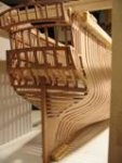
Here are some more pictures of the cant frames. These gave me a bit of trouble due to the multiple tapers on them and I ended up making several of each piece before getting some I was happy with.
Next comes the cant frames forming the bow. I did a short video for Jeronimo that illustrates how cant frames for the Richard are laid out, cut, and placed on the model. The link is here
.A lot of ships from this period had cant frames and bows constructed in a similar manner so the video might be useful to reference.


 Jeronimo got a reaction from JerryGreening in LE BONHOMME RICHARD by Jeronimo - FINISHED
 Jeronimo got a reaction from Wishmaster in LE BONHOMME RICHARD by Jeronimo - FINISHED
 Jeronimo got a reaction from Luca in LE BONHOMME RICHARD by Jeronimo - FINISHED
 Jeronimo reacted to rekon54 in Le Fleuron 1729 by rekon54 - 1:24