

Jeronimo
-
Posts
716 -
Joined
-
Last visited
Reputation Activity
-


-

-
-
-
 Jeronimo got a reaction from Wishmaster in LE BONHOMME RICHARD by Jeronimo - FINISHED
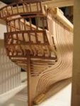
2nd Construction stage - Bow part
posterior third of the ship with all equipment and view of the interior the model.
Regards Karl
T e i l 1
-
Jeronimo got a reaction from Wishmaster in LE BONHOMME RICHARD by Jeronimo - FINISHED
Hi friends.
Great problems in the preparation of the Hawse-Timbers - Cant Frames.
Thanks to the help of Jerry, Richard and David / Druxey was able it be solved.
Regards Karl
T e i l 2
-
 Jeronimo got a reaction from greenstone in CHALOUPE ARMÉE EN GUERRE 1834 by Jeronimo - FINISHED
Teil 8
-

 Jeronimo got a reaction from Ainars Apalais in CHALOUPE ARMÉE EN GUERRE 1834 by Jeronimo - FINISHED
Teil 8
-
 Jeronimo reacted to EdT in HMS Naiad 1797 by EdT - FINISHED - 1:60 - 38-gun frigate
1:60 HMS Naiad 1797
Part 12 – Beveled Square Frames
Posted 10/29/10
Below is a pattern sheet and a pdf for frame 20A, one of the more highly beveled square frames - a few frames forward of the aft cant frames.
This pattern sheet contains all the information in the pattern for the deadflat frame example discussed in part 11, but there are some differences.
Because this frame is beveled to account for increased curvature of the hull in this section of the ship, two sets of profile lines are shown. The green lines describe the forward face and the brown lines describe the aft face. Also, the keelson is higher at this frame as is the top of the rising wood at this location. Finally, on this particular frame, all the timbers are centered fore and aft on the floor, unlike the previous example, in which all the aft faces were aligned. All these fore and aft alignments were taken from the disposition of frames drawing. These alignments varied to provide adequate air space and to place gun port sides at their proper spacing. This adds an assembly complication, which will be discussed below.
Following is an image of the worksheet used to develop this pattern.
This worksheet was used like the worksheet in Part 11, with additional steps. This worksheet includes a plan of the aft frame locations and to the right of that a sheer plane view of the lines describing the top of the rising and the bottom of the keelson. These are needed to set these locations on frame patterns toward the ends of the hull.
Profiles from the left view are copied and pasted on the right view as before, but now there are two profiles because the fore and aft faces are different. Also, because the aft square frames are on the right side of the body plan they are placed on the right side of the pattern template.
Because this is the aft frame of the pair, the number 20 frame line profile is used for the forward face. The dashed line between profiles 20 and 21 is used for the aft face. The use of these additional dashed lines for frames that have significant beveling improves the accuracy of the pattern. The primary benefit of this, besides reducing the amount of fairing needed, is that it helps set the bevels of the chocks accurately, which reduces the chances of cutting into a chock joint when fairing, either inside or out. It also improves the accuracy of the aft inboard profile which is a saw cut line.
To set the heights of the rising wood and keelson bottom, points are set on the bottom right view, then transferred to the pattern view by way of the diagonal line, using the red transfer lines. These heights are different for the fore and aft faces, so four lines need to be set.
The inboard lines are then drawn as before, joint lines are set, all these lines are copied, pasted and flipped, and as before all the objects are transferred to the pattern sheet.
With the lofted pattern in hand, the next step is to mark out the chocks as before. However, because the frame is beveled this procedure needs to be modified. The picture below shows the first step in this process for beveled frames.
Because the frame is beveled, the chock joint surface must be beveled as well, which means that a chock joint line must be put on the pattern for both the fore and aft faces to define this surface. However, because the chock will be angled in the frame it must angled before tracing, because tilting the chock changes the apex angle on the face of the frame. The above picture shows how the chock blank is marked for beveling to get the right angle for tracing. If the chock blank thickness is close to the thickness of the frame, the amount to be removed from the apex side is about equal to the distance between the fore and aft profiles at that point. This approximation is adequate to yield a good joint and is being marked with a pencil in the above picture..
Below a chock blank is being beveled back to the mark made above before marking the frame.
Now the blank can be used to mark out both fore and aft joint lines and this is shown in the next two pictures. The beveled face should be held down flat on the pattern for this. The next picture shows tracing of the joint line for the forward face and the following picture for the aft face.
The next picture shows the beveled chock joint lines and notes the line to be cut out on the saw.
The paper patterns are now cut out and pasted to the appropriate size wood stock exactly as described in Part 11 and the segments are cut out and finished on their ends in the same way.
When cutting the chock joint line, however, the cut should be made on the innermost line as shown above, in this case the aft joint line. The next picture shows a set of these after cutting out.
Once cut out, each sawed chock joint face is dressed with a file to bring it even and square with the pencil line used for the cut. It is then beveled to the line on the other face as shown in the following series of pictures.
First, using a fine toothed saw, an angled cut is made down to the forward chock joint line, while not cutting into the back face.
Now, please do not be confused by the fact that while the last picture showed an aft frame with a smaller aft profile, the next three show a forward frame with a smaller forward profile. These example pictures are not all the same frame, but the process is the same. Sorry for this.
So, in this next picture, the first paring cut on the deeper (in this case the aft) chock line is being made. I use a skew chisel for this because I find it easier to control than a square chisel. The idea here is to pare down the corner of this edge to the pencil line.
In the next picture the corner is being removed in the opposite direction. Care is needed here to watch the grain direction and avoid chipping off the end of the piece. Small cuts and a very sharp chisel are in order here.
In the last paring step, shown below, the ridge left in the center is pared back leaving a flat surface for the chock. As a final step this is dressed smooth and flat with a file.
The chock is then fit as shown below and then glued and clamped.
When the glue has dried the bottom surface is sanded flat as before and the frame assembled on the pattern exactly as before, but before fitting up additional segments the joint surfaces of each needs to be pared and fitted to their mates as described above.
As noted on the pattern sheet, this frame has all its timbers aligned on the centerline of the floor. To do this, shims, which have been cut to the thickness of the offsets are placed under the upper futtocks to hold them at the correct fore and aft placement in the assembly jig. Otherwise the frame assembly and finishing off process is exactly like that described in Part 11. A variety of these shims ranging from 1 inch up to 3 inches are kept on hand for this.
In the case of this frame, with its upper segments on the floor center, there will be offset joints to pare back on both sides of the frame in the finishing process.
In the next segment, the lofting and fabrication of the cant frames will be discussed.
Cheers,
Ed
2013 Copyright Edward J Tosti
-
Jeronimo reacted to EdT in HMS Naiad 1797 by EdT - FINISHED - 1:60 - 38-gun frigate
1:60 HMS Naiad 1797
Part 11 – Frame Assembly
Posted MSW 10/27/10
Frame Assembly Jig
With eighty-three square frame sections and seventy-eighty cant frames to be made, some sort of assembly jig was certainly appropriate. A picture of the basic jig developed for this is shown below.
The work surface is a piece of melamine-coated particleboard with the center area sized to fit a letter sized pattern sheet. Slotted wood assemblies on the sides hold down clamping strips, which will hold frame segments in position on the assembly pattern sheet. The side trays hold clamp parts. Below is a picture of this jig in use on the glue up of a cant frame.
Hardwood cross members are drilled and tapped to take tightening screws at a variety of locations. These tighten down onto hardwood strips below, which bear on the frame pieces. The ends of the cross pieces are held down by the side slots. Each clamp also has two screws, which fit loosely through the top members and screw into the bottom strips to hold the assembly together.
Having described the assembly jig, we will pick up where we left off in Part 10.
Frame Assembly
After chocks have been glued to the heads of their segments and their backs leveled off on the disk sander, as described in the last part, the lower pieces are clamped down on the assembly pattern. The adjoining segments are then fit up to it. Usually some file dressing is needed to get a precise fit. The clamps hold the timbers in place so any adjustments can be checked easily. When the joint fits well and the parts match the pattern, they are glued together. The hold-down clamps are applied first to assure the parts stay on pattern. Then clamps are put over the joints. This is shown in the picture below.
This picture also shows shims under the upper futtocks to provide the correct offsets in the fore and aft direction. This particular frame has all the forward faces aligned, so progressively thicker shims are needed under the upper segments so all the top (fore) faces are aligned.
Finishing Assembled Frames
The picture below shows a square frame ready for the last finishing steps.
A this stage the frame has been removed from the jig, the inside of the chocks have been cut back to the inboard profile on the scroll saw. The frame has been sanded down very close to the outboard and inboard profiles on a vertical drum sander, but no beveling is done at this stage. The notch to fit over the rising wood has been cut out and filed to fit. In this picture the frame is being matched up to the assembly pattern for a last check.
The next step is to pare down the excess chock widths on the front face and to finish off these joints in preparation for erection of the frame.
The simple clamping device below was helpful in the paring process. It also helps avoids chiseling into fingers.
To make this, a 1inch dowel has slices cut off, just less than the frame thickness. Holes in these for screws are drilled off-center. Sandpaper is glued around their perimeters to help grab the work. They are then screwed loosely to a piece of plywood, which has a bench stop under its front side. The curved frame can then be pushed between the off-center discs and the cam action of the disks will hold it in various positions for paring.
The next few pictures illustrate finishing off of joints to the smaller siding of the upper piece, and if necessary, for any other jogging called for. This is done with a paring chisel and then dressed off with a small file.
.
.
.
.
.
As mentioned earlier, I leave the paper on until it absolutely has to be removed, to help in alignment and, on beveled frames, for rough faring of the inboard face after erection. In the above picture, paper has been filed off at the joints in the finishing process. When doing this, a file card is kept handy to remove paper residue from the file.
Floor Fillings
The picture below shows a final step for certain frames.
In this picture a filling piece of cherry has been cut which will be glued to this particular frame to match its floor. In practice these fillers were inserted between floors after erection to provide a continuous surface to help prevent bilge water from filling the spaces between frames. On the model these add authenticity and are very helpful in spacing floors correctly. Since floors of main-frame bends are bolted tightly together, these are used only in spaces adjacent to intermediate frame floors. There are three such spaces for each pair, one between intermediate frame sections and one each between these and their adjacent main-frame bends.
These fillers vary in thickness based on the disposition of frames drawing, averaging a little over 2 inches thick. They were glued to the frame before erection and then sanded off as necessary to match the required spacing. These fillers also add a lot of strength to the model in this area.
In the next part I will discuss how the preceding lofting and assembly process was modified to handle square frames with bevels.
Stay tuned…
Ed
2013 Copyright Edward J Tosti
-
Jeronimo reacted to EdT in HMS Naiad 1797 by EdT - FINISHED - 1:60 - 38-gun frigate
1:60 HMS Naiad 1797
Part 10 – Frame Lofting and Fabrication
Posted 10/25/10
With the completion of the stern timbers, work could begin on the hull framing, starting with the cant frames then working toward midship with the square frames. As I said earlier, this put the difficult work first and gradually progressed toward the easiest framing work – the unbevelled midship timbers.
However, I want to do the discussion of the lofting and fabrication of the frames in the reverse order, starting with the easy midship frames and ending with the more complicated cant frames. After that I will discuss the erection of the frames on the keel in the order I followed. I believe this will make the lofting discussion, in particular, a lot easier to follow.
Midship Timber lofting and Fabrication
On Naiad, the square frames, those that rest perpendicular to the keel, ran from frame Q in the forward body to frame 24 aft. Each frame line, except for one, had two frame sections.
For the main frames (2,4,6...B,D,F etc) two sections were bolted together to form frame bends. On these, floors were bolted directly to the lower futtocks, but above the floor heads bolts passed through spacers to maintain air space. On the original ships these spacers were bored vertically on either side of the bolts to allow air circulation to the lower regions.
Intermediate frames, odd numbered and lettered, stood alone with space between them. Altogether there were 83 square frame sections. Each is identified by its letter or number and by the letters A or F to designate whether it is the aft or forward section of the pair. Very few, if any of these are completely identical, although several at midship have identical profiles.
Here is the pattern for the forward frame of the Deadflat bend and a pdf version, which will be more readable. A letter sized pattern sheet like this was made for every frame section.
Each pattern has identity information and a revision date. Since this is the first use of these drawings, corrections are being made and the revision date keeps these straight.
The pattern obviously includes the inboard and outboard profiles of the timber, but also some additional information to assist in constructing the frame:
All the diagonals, based on the original draft are shown. Each of these has a defined purpose, which is explained in a note on the worksheet below.
Joint lines are shown cutting through the profile at the appropriate diagonal for this section. In this case the floor heads and the heads of the second futtocks are marked at diagonals 3 and 7.
The siding (fore and aft width) of each component is given so it can be cut from the right size stock.
A large standard reminder of which frames have floors (vs. lower futtocks) is on every sheet.
Finally a notation, in this case “Aft faces aligned” tells how this frame is to be assembled. In this case it’s simple. All the aft faces are in a line.
Below is a simplified version of the worksheet used to loft this frame. Four worksheet templates were developed to loft frames of the following types: fore cant frames, aft cant frames, fore square frames, aft square frames. A copy was then made of each of these to develop a particular frame section then saved in case revisions or checking of that section were needed later.
This worksheet is used as follows to develop the pattern:
First the appropriate profile is selected from the partial body plan to the left. It is copied and pasted in the correct spot on the view at the right, which has all the basic construction lines on it.
The red circles on the left side of the right view are then used to set points which will be connected with a curve to define the inboard shape. The diameters of these circles are taken from the scantlings for each location up the frame. The red text indicates the molded breadth at each point, which is the basis for the red circles. Circles were adopted because in CAD they make placement of the inboard points very easy when placed tangential to the outboard profile at each point. The inboard point can then be placed on the inside circle tangent, eliminating angled measurements.
The lowest inboard point is set at the bottom corner of the keelson. The points are then connected with a curve and this defines the inboard profile.
The joint lines are added at the correct diagonal. A description of the diagonals is in blue text.
Once one side is formed, it is copied, pasted, flipped and positioned on the opposite side. Both sides, the keelson and the keel assembly are then copied and transferred to the pattern sheet as one object, where it is positioned on the basic frame reference lines – top of keel, centerline, diagonals and other key lines.
Midship Frame Fabrication
Two copies of each pattern were made. The first was used for marking chocks, then cutting and pasting patterns for each part on the wood stock. The second was used as a template for assembly.
All frame components are joined together with chocks like the original. I started out showing chocks on the patterns, cutting out the timbers, then making chocks to fit. This involved precisely cutting the seat for the chocks and then doing the same for the chocks themselves.
The simpler process I adopted is shown below. It obviated the need to draw all the chocks on the patterns and reduced the amount of fitting work. This approach saved even more time when it came time to do beveled chocks. So, based on this approach, the frame pattern drafting was changed to show only the joint line – no chocks.
In the improved process blanks from which chocks can be sliced off are shaped. One approach is shown below.
I soon adopted other approaches. These blanks can be made by tilting the table on the disk sander and beveling with the disk – making a lot of dust. Another way is to hand plane down the rough shape then clean it up on the disk. This is my current approach. Blanks with a few slightly different angles were made to fit different frame curvatures. Once these were beveled, the shaped face could be ripped off on a band saw for use.
The blanks are then used as shown below.
In this picture I am marking the chock joint line on the pattern. This is the first step in making a frame by this process. In this case it is the large chock between lower futtocks. The chock should be placed so its ends are about 1/3 into the frame.
The chock joint line for the head of the first futtock is being marked out in the picture below. The chocks blank selected should allow the apex of the chock to be positioned about one-third of the frame thickness from the outer edge and about the same from the inner. This is the reason for making a few slightly different shapes.
In the above picture the large center chock has been sliced off the blank. Before cutting this off, I marked the bottom side and then sliced it off on a circular saw. It is important to cut the chock from the end used for marking and make sure one side is identified, so it will fit its frame correctly. This procedure also avoids having to make chocks perfectly symmetrical.
Individual timber patterns are then cut out and pasted to the correct thickness wood stock as follows:
First, using a sharp X-Acto type knife and a straightedge, cuts are made along each of the pattern joint lines. This defines a precise mating joint between timber segments. The pattern segments are then cut out and pasted to the pear stock of the appropriate thickness. Some of these are shown ready for cutting out below.
Timbers were cut out leaving about 1/32” excess around the pattern lines, including the cut off end of the joint line. The joint lines were then sanded back precisely to the cut paper line as shown below. Once I settled on this approach for trimming the ends of the timbers, I could get by with one unexploded frame pattern for all the cutouts.
If this sanding step is done carefully, right up to where the paper was cut, the pieces of the frame will line up pretty well with the profile when butted together. The next step is to cut the chock joint lines. This is shown in the next picture.
The cuts are made just inside the pencil lines, then dressed with a file. Chocks are then fit and glued to the heads of each frame segment, making sure the chock is oriented correctly to the way it was traced. If care is taken to this point the chock should fit pretty well.
It is then glued to the futtock and clamped.
]
Chocks are fitted and glued to all the futtock heads and set aside to dry as shown below. This is usually the time to start marking chocks on the next pattern.
When the glue has dried, the bottom side is sanded off flush on the disk sander as shown below.
At this stage the frame is ready for assembly. I will cover that in the next part.
Ed
2013 Copyright Edward J Tosti
-
Jeronimo reacted to EdT in HMS Naiad 1797 by EdT - FINISHED - 1:60 - 38-gun frigate
1:60 HMS Naiad 1797
Part 9 – Stern Transoms Wrap Up
Once the transoms had been finally secured to their fashion pieces the assembly could be glued to both the sternpost and the deadwood, bringing to conclusion a challenging and interesting piece of work.
Here is a picture taken at this stage and after some tidying up of the work space.
This stage was reached at the beginning of May. The transoms were very roughly faired both inside and out. The sternson knee is also shown here pinned in place to help with the fairing.
The next step was to do some further fairing of the outside and install the four vertical filling pieces under the lowest transom. The following picture shows the lower transoms still largely unfaired, but the mortises have been cut in the lowest transom for the vertical filling pieces.
Here is a view of these mortises on the port side.
In the following picture some additional fairing has been done and the four starboard fillers have been rough cut without patterns, tenoned and fit into place on the starboard side.
These were installed on both sides and were faired as shown in the next picture.
The way was now clear to begin work on the aft cant frames. I will cover that in the next part and insert a section here on miniature woodworking clamps that have greatly facilitated much of my model making work.
Clamps
In the last section I mentioned the need for special clamps. A lot of my homemade clamps were in previous pictures. There are two types, one is just a miniature version of the Jorgensen style woodworking clamps that I have used a lot and find to be extremely flexible in a variety of situations. The other type is a simpler version and quite easy to make. The Jorgensen type are more involved. I will describe the easy ones first. Here is a picture of some of these.
Most of the jaws are made of maple about ¼ inch square. The ends are tapered down so they will get into tight places, like between frames. Brass 6-32 threaded rod is used for the screws. The clamps are all oriented the same way in the picture for ease of explanation. In all these the top rod is threaded (in the wood) through the top end of the right jaw piece. The upper right hand clamp shows how the end of the upper rods are turned down to fit a hole in the top of the left piece so the rod can push against it. The bottom rod slides through a slightly oversized hole, unthreaded, in the middle of the left jaw piece and is threaded through the right jaw piece in the middle. Holes are of course all lined up. Sometimes gluing sandpaper between the jaws helps them grab at an angle. The knobs are turned, drilled, threaded and then screwed and epoxied onto the rods.
This has probably been confusing enough so I will not try to describe how to use these. They take some getting used to, but briefly tightening either knob will tighten the clamp if the left hand knob is in contact with the left jaw and the turned down end of the upper rod is in the hole in the right jaw. They can apply a lot of pressure. Some with long jaws or long rods, have a tendency to twist if not well aligned.
The second type is more complicated and more versatile. Some are shown below in an older picture with some miniature London pattern paring chisels.
These are more complicated and making them requires some investment in both right and left hand 4-40 taps and dies. The jaws are also maple. The rods are threaded to the middle - at one end with a right hand thread and at the other end with a left hand thread so that turning one knob either tightens or loosens one end of the jaws. The rods are threaded through 1/8 inch diameter brass rod segments, which can rotate freely in the holes through the jaws. The holes in the jaws for the rods are really slots so the jaws can angle in different ways. Handles are threaded into the ends and epoxied. The brass ferrules are a little unnecessary extravagance. The handle end of the rod in the middle is right-handed. The handle end at the back end is threaded left-handed. Also, I later enlarged the slots that the threaded rods pass through to allow them to angle more freely. I have larger ones of these with jaw sizes rom three inch to twelve inch.
These do well in clamping non-parallel surfaces. They can also clamp parallel surfaces that are not aligned and of course they can clamp parallel aligned surfaces. These also benefit with sandpaper glued to the jaws. . These are very flexible clamps, which again, take some getting used to.
In the next part I will discuss lofting and fabrication of frames.
Ed Tosti
2013 Copyright Edward J Tosti
-
Jeronimo reacted to EdT in HMS Naiad 1797 by EdT - FINISHED - 1:60 - 38-gun frigate
1:60 HMS Naiad 1797
Part 8 – Stern Transoms
The stern transoms were the next step in my plan from difficult to easier. Because of some careless drafting of a couple of the supplementary waterlines at the aft end of the ship – the butt of the hull - the first completed transom assembly included some transoms that were too small and it had to be scrapped, adding to the growing pile in the scrap box. I would happily have hidden this fact, but I used a different process for the second assembly than the one I devised for the first and I believe both may be of interest, so I will describe both.
First, a picture of the finished version 2 assembly – the final version.
This picture was taken in June, so a lot more work had been done by that time, but it shows the features of the stern transom assembly pretty well. By the time of this picture many of the aft cant frames had been installed, but I will ignore that for the time being and stick to the transoms. There are six of these. The lower four filling transoms are tenoned into the after fashion piece (AFP). The third one from the bottom is a deck transom, so it is rounded up to match its deck. The topmost filling transom rests on the top of the AFP and both it and the wing transom are tenoned into the forward fashion piece (FFP). All the transoms are fit into mortises on the inner post, which were shown in earlier pictures. The four vertical filling pieces are tenoned into the bottom of the lowest transom with their feet resting on the upper end of the bearding line ledge. It is a fairly complicated structure.
Some may have noticed a slight anomaly in this picture. I will point it out later. It is easier to find than to explain. So if anyone can explain it, they will have my admiration. It was an interesting problem.
Lofting and Making the Transoms
To help define the shapes of upper and lower surfaces of the transoms, additional waterlines were drawn from the final body plan at 1 foot intervals in this stern area of the Full Breadth Plan – the one pasted to the board. The heights of these lines approximated the upper and lower edges of the transoms so were used to loft the transom shapes. Once the initial errors in these waterlines were corrected, this worked out fine, as long as some excess was provided when cutting the shapes. The tenoned faces for the transoms were of course, defined by the after edges of their respective fashion pieces.
With the patterns in hand the transoms were cut out, very roughly beveled and fitted snuggly into the mortises in the inner post. The next step was to cut the tenons and fit these into mortises on the fashion pieces – some complicated joinery at 1:60 scale.
Assembly Version 1
This next picture shows how I approached this the first time through.
The first step was to set up the upper two transoms, which would be tenoned into the forward fashion piece (FFP), in their correct final position. Spacers of the precise thickness of the space between them were then temporarily glued to them on either side of the stern post. Then spacers of the same thickness but of a longer length were glued between them exactly on the line of the aft face of the (FFP). Triangles were used to set these angled pieces from the drawing on the base. Note that the corners of the clamped squares are set on the corner of the FFP on the drawing and on the piece. This picture was actually taken a bit later after the wing transom tenons were cut. The next picture shows the tenon milling set up.
In this picture a dial indicator is being used to assure that the milling cut will follow the correct angle precisely, defined by the edge of the long spacer. The piece is adjusted in the vise until the indicator remains at zero as the vise is traversed. The long length of the spacer reduces error in these measurements. The next picture shows a tenon being milled. [
In this picture the tenon is deeper than needed and will be trimmed back to fit snuggly into the mortise after that is cut. In all cases the depth of the tenon was cut to the shoulder line defined by the long spacer and the width was set by the calibrations in the cross feed so that every tenon was precisely the same width.
To cut the mortises in the fashion pieces, they were first set up against the squared up transom assembly after the tenons had been cut. The frame was then marked with the tenon locations using a very sharp pencil. The mortises were then cut with a very small hand chisel. The next picture shows the assembly ready to be glued up.
It was important at this stage not to fasten the fashion piece permanently to the deadwood or the transoms to the post. This would prevent the addition of the lower transoms and their fashion pieces.
This is another view showing the glue up of the top two transoms.
The next picture shows the final assembly of the lower transoms and their fashion piece. This was made using a slightly different process that I ultimately adopted for the final assembly version.
When these two assemblies were fit up and fastened, there were two problems. One I mentioned above. The other was that there were some small gaps where the transoms joined the inner post, which could not be easily corrected. Either one of these problems would be sufficient reason to scrap this work and that is what I did.
Assembly Version 2
The main difference in this final, and I believe better, process is that it is much more incremental, allowing final fit up at each step of the assembly. Here is how it was done.
The picture below shows how each transom was marked for machining of its tenons.
In this set up, the transom, in this case the wing transom, was set in final position on the post and squared up. Two very flat pieces of plywood were set up with the clamped squares so that the aft side of the plywood coincided with the forward face of the fashion piece, in this case the FFP, to which that transom is joined. When this was done, a small strip of wood, equal in thickness to the fashion piece was held against the plywood and a line was made on the transom along this strip. This line is where the transom will join the fashion piece – the shoulder of the tenon. After marking, the transom was removed and a second line was drawn on each end to show the end of the tenon. The piece was then trimmed back to this second line on the disk sander.
The next picture shows a lower filling transom set up for machining.
In this picture the dial indicator is used as before but this time with less length to traverse. There are other ways to do this. A strip of wood could be set on the vice and the tenon face aligned with it. All these approaches seem to yield sufficient precision.
Once each transom was tenoned, it was set up on the post and a line was drawn on the fashion piece to mark the top of the transom. When removed, mortise lines were added. The mortises were then cut by hand as before. The fashion piece was then fit up to the transom and everything checked for alignment and tightness of all three joints – one transom at a time, starting at the bottom. This approach assured a good fit at each transom fit up.
The following pictures show these transoms being glued up, one at a time from the bottom – to the fashion pieces only – not to the post. Again the fashion pieces are only pinned temporarily to the deadwood until the whole assembly is finished.
In this picture the second lowest transom was being glued. First, the previous assembly had been moved forward, the new transom set on the post and then the assembly brought back into position and the fashion piece glued and clamped. These things were difficult to clamp. There are two variations of clamps that I had made years ago and those, plus some new ones, came in handy for this. I will describe these clamps in the next chapter.
The next picture shows the (conservatively sized) upper deck transom being glued.
Because of the round up, the fitting of the deck transom required some special handling. First, it was, of course, made from thicker stock measuring precisely the thickness of the timber plus the round up. Before fitting to the post the center part only was cut back on the bottom by the amount of the round up so the notch into the post could be fit. The ends needed to be left unshaped so they would be square in the milling vice. The tenons were then cut from the bottom edge, leaving excess to be removed from the top, which was then done. Both bottom and top were then rounded to the correct profile. The wing transom, which is also rounded up, was handled in the same manner.
One point worth mentioning regarding deck round up is that it is specified at mid ship. At the ends the deck is less wide, so round up of the transom needs to be reduced accordingly.
The next picture shows the top filling transom being glued to the tops of both AFPs, and also to the starboard FFP, which is also being glued to the starboard AFP. The port FFP was glued later.
Below is another view of this step. Note the tenon on top of the inner post. It was about to be removed. Why?
Finally the attachment of the wing transom. Like its predecessors, it was set on the post and the assembly, still not glued to the deadwood, brought up to meet it so it could be glued to the FFP. This is why the tenon at the top of the post had to go. Otherwise the assembly could not be removed. An alternative would have been to glue the fashion pieces to the deadwood and all the transoms to the post at this step, but I wanted to take this slow and make sure everything fit. The post tenon is hidden, anyway – but now you all know its not there.
These last two pictures show how conservative I was in sizing this last rendition of the wing transom.
I will wrap up these stern transoms in the next part and discuss clamps.
Has anyone found the anomaly in the first picture? It has something to do with the last two pictures.
Ed Tosti
2013 Copyright Edward J Tosti
-
Jeronimo reacted to EdT in HMS Naiad 1797 by EdT - FINISHED - 1:60 - 38-gun frigate
1:60 HMS Naiad 1797
Part 7 – Hawse Timbers
Posted MSW 10/20/10
Once the basic centerline backbone of the ship was in place, I elected to tackle the forward timbers that fill the space between the stem and the first cant frames. I then planned to do the stern transoms, then the stern cant frames, then the fore cant frames, then the fore square frames and finally the aft square frames in that order working toward midship. I did not appreciate at the time that this plan started with the most difficult work then proceeded with steadily decreasing difficulty to the easiest work last. So, right into the deep end. . . .
The forward timbers sent me directly back to the computer to draft profiles and to loft the patterns from which they could be cut. Since the hawse timbers are butted together with the vertical joints essentially parallel to the keel, profiles for the outside edge of these joints could be constructed by transferring points from longitudinal body curves (waterlines, heights of breadth, etc.) on the plan view, down to their corresponding lines on the vertical, or sheer plane, view, then joining these points with curves. There are five of these joint lines on the outboard faces of these timbers. The first describes the outboard inside edge of the first timber, the second the outboard outside edge. The second also describes the inside edge of the second, the third its outside edge, and so on. Below is a picture of the patterns for these timbers showing how the numbered profiles form outside and inside edges of each outboard face.
The inboard edges presented a more difficult problem, and frankly, a more complex drafting solution, which I decided to skip. Instead, I conservatively estimated the shape of the inside edge, and decided to finalize these inside shapes during construction. The dotted lines in the above drawing represent these estimated lines.
The hawse timber profiles were cut out on the scroll saw and their forward outside edges roughly beveled. Inboard faces were even more roughly beveled leaving most of the work until after assembly. The 34.5 degree bevels at the foot of the timbers were done on the disk sander with the table set to that angle. This left a very accurate, flat, glass-smooth surface. I normally use 220 grit on the disk.
Before the first hawse pieces could be installed, it was necessary to make and erect the forward fashion pieces and the first cant frame, which the hawse timber feet butt against. The port assembly of these three timbers is shown below.
This part of the Admiralty framing draft was not well drawn and it is somewhat unclear how these pieces were to be arranged. With some help from the White book on Diana and some interpretation, I concluded that the bollards and first two hawse timers butt against the first fashion piece, the third against the second, and the fourth against the first cant frame. The fifth is really just a small triangular filling piece. This arrangement can be seen in some of the later pictures.
I will go into some detail on the drafting and making of cant frames later in the story, but these were the first to be made. Note in the above picture that the large clamped square at the left has its corner set at the corner of the first cant frame on the drawing and the top of that frame set at the same point on the corner of the square. This is one way that cant frames were positioned.
The vertical beveled faces of the two fashion pieces needed to be carefully surfaced and set up parallel to the keel so that they would match up to their correct hawse timber faces.
Unfortunately, I did not take pictures of each step of this construction, but below are some pictures taken after all were installed and rough faired, inside and out.
In the above picture and the next few, all the hawse timbers, the fashion pieces and the first cant frames have been installed and rough faired inside and out using some of the tools lying about in these pictures and also a rotary tool. The outside profile was faired first. Then based on the scantlings at each height, measured with the calipers lying on the board just off the starboard bow, the inside surface was shaped back.
This picture shows how these timbers fit together against their respective fashion pieces and the first cant frame. Before attaching each one to its neighbor, the air gap of about 2” was created by paring back each adjoining face from the foot up to a point somewhat below where the hawse holes will eventually be bored. When gluing adjoining pieces together and at their feet, temporary 2” spacers were inserted to maintain this gap.
The picture below is a closer view, showing a few things worth mentioning. The forward extension of the keelson is shown pinned in place temporarily, mainly to help bring the forward fairing to a neat closure with it. Also shown is the sturdy pine support, which will keep the fore part of the hull vertical throughout construction. A few little faults are also apparent. The burn marks from the rotary tool on the starboard side will eventually be covered with internal planking, after which they will no longer irritate me. There are a few exposed holes drilled for locating pins that can be seen, reflecting the difficulty I had in visualizing the final limits of these timbers. All in all, I was pretty happy when I reached this point.
The last picture shows the whole assembly on the starboard side after the addition of the second cant frame, which was directly bolted to the first to reinforce this whole front structure. The joints between futtocks in both these frames can be seen clearly here. They are chocked on the inboard side and will be strengthened with copper bolts.
It would be untrue to say all this went smoothly, and my box of scrapped parts will confirm this, but now that I’ve done it once, I think I understand the structure and it will be a lot easier next time.
This stage was reached in the middle of March 2010.
Ed
2013 Copyright Edward J. Tosti
-
Jeronimo reacted to EdT in HMS Naiad 1797 by EdT - FINISHED - 1:60 - 38-gun frigate
1:60 HMS Naiad 1797
Part 6 – Stern and Stem Construction
Original post 10/18/10
Stern Deadwood
After the timbers of the aft deadwood had been fayed and glued together, the next step was to reduce the deadwood above the bearding line to the final width of 14 ½ inches. This width is equal to the full breadth of the deadwood, 18 ½ inches, minus the 4 inches required for the two 2 inch ledges to support the cant frames. These ledges follow a curve on each side of the hull called the bearding line. On Naiad, this was a continuous curve, not stepped.
The bearding line needs to be located accurately so that when the hull is faired the feet of the cant frames remain at roughly their 2 inch thickness (.033” at 1:60) and do not get faired down to less or, in the worst case, nothing. The bearding line can be copied from the original draft and put on the CAD version, but I think it is preferable to develop this line directly from the CAD body plan profiles, which are being used for all the other lofting.
The bearding line passes through all the points on the hull at which the moulded breadth of the hull is equal to the deadwood thickness - 18 ½ inches. Placing a vertical line on the body plan at half this breadth from the middle line, allows heights to be taken off at each frame line to plot the bearding line in the sheer plane. This was the approach used to plot the forward and aft bearding lines on the Naiad CAD drawings. The bearding line was a bit of a mystery to me until I visualized it in this way.
With a pattern for the aft bearding line in hand, the line was then marked out on the stern timber assembly, which was then set up in the milling machine as shown below.
The next picture shows a closer view of this setup.
I will not walk through all the steps of this milling process, but only touch on a few points. First, the work, of course, must be horizontal when milling both faces, so the assembly, which when finished will be narrower at the bottom, was not tapered until after this process was complete. Second, the machining was only carried up to within, say 1/16 inch of the bearding line, leaving the final cutting to be done with hand chisels. Finally, with the top deadwood machined to its final width, the centerline of the assembly was then determined from this and marked on all edges of the piece.
After this machining, the sternpost and inner post assembly was attached and the whole fastened to the keel. In the following picture this assembly is shown shored up by one of the clamped squares discussed in Part 4.
Again, at this stage I was taking few pictures. Cutting out and shaping the sternpost assembly was fairly straightforward. Heights and sizes of the mortises for the transoms were taken from the large Centerline Structures drawing.
The stem, apron and forward deadwood assembly was made and attached to the keel in much the same way as its aft counterpart. Here is an image of the pattern sheet for the forward structure.
There are more complicated components here, but the process is essentially the same. A separate pattern sheet was made for the knee-of- the-head parts. When all these parts were assembled and attached to the keel, the entire assembly was set up as shown below.
Permanent supports for the beakhead and sternpost were added later to replace the temporary clamped squares shown in this picture holding the ends vertical. The keel was maintained on center with the small wood blocks screwed into the base with another placed just behind the sternpost.
In the above closer side view, the bearding line still needs a little trimming and the stem rabbet has only been cut at the top, leaving the section down to the keel rabbet still to be done. The “rising wood,” that is, the deadwood in the center section of the hull is also visible in these pictures.
This picture shows the details of the beakhead assembly with the gammoning knee in place and also the initial fitting up of the bollard timbers. The picture below shows another view of this.
In the following picture the bollard timbers have been installed, the knightheads shaped and the bowsprit chock installed. Also the first forward cant frames on the port side are being positioned, but I will save the cant frame discussion for later.
The bollard timbers have a complex shape. The inside faces are curved to match the curvature of the sides of the stem, which expands in breadth as it rises from the keel. The fore surface matches up to the curved rabbet of the stem, then curves aft matching the hull profile. The aft (inside) surfaces are curved to maintain the correct molded breadth at each height. The aft foot is beveled 34.5 degrees vertically with its edge fitting into a relief cut at the same angle in the apron piece above the bearding line. The outside edge, which is thankfully flat, is cut back about 1 inch over most of its length to give an air space when the first hawse timber gets butted up against it. Finally, there is a complicated bit of fancy joinery needed to get the bowsprit retaining chock to fit neatly between the upper parts, called the knightheads, which get their own little bit of shaping. The next picture is a closer view of all this.
These bollard timbers turned out to be simple forerunners of what was to come with the modeling of their neighbors, the hawse timbers, which will be covered in the next part.
Hold Down Bolts
At this stage it was necessary to bolt the keel down securely to the building board, and it was a relief to turn to some work I could get my mind around. For the hold down bolts, special threaded studs were machined in brass as shown below.
Three of these were made and were spaced out on the keel. Eventually they will be the permanent mounting bolts for the model. The idea behind this design is that the smaller diameter threaded part of this (4-40) will come up through the keel. The shoulder of the larger diameter will be stopped at the bottom of the false keel. Three small (4-40) nuts from above and three larger nuts from below will hold the keel down, initially. Eventually a small nut will be embedded just below the keelson. With the shoulder screwed up against the keel bottom, the top of the small section will be cut off flush with the top of the nut. This will prevent the keelson from being popped off by over-tightening this bolt from below later. The larger size nut under the building board or the base of the case will then hold the model down.
All this work was completed by the end of February 2010.
Ed Tosti
]2013 Copyright Edward J Tosti
-
Jeronimo reacted to EdT in HMS Naiad 1797 by EdT - FINISHED - 1:60 - 38-gun frigate
1:60 HMS Naiad 1797
Part 4 – Devices and Tools
Special Devices
The first items to be constructed were the building board and some measuring tools. The building board is shown below, clamped to a woodworking bench top.
The board itself is a piece of ¾ inch medium density fiberboard (MDF) with some pine stripping around the sides. MDF was chosen because it is very flat and smooth. Two slots were dadoed into the top to take lengths of T-track. The board was then mounted on the 2” X ¾” pine framing salvaged from the Victory building board and screwed down along the sides and near the middle. It was checked for flatness and shimmed underneath in a few spots to make it perfectly flat and well supported by the frame. Before assembly the top and bottom were given two coats of white shellac to seal its porous surface. The top was then sanded and given two coats of flat acrylic latex paint. The centerline for the keel was scribed into the top midway between the two T-slots and a print of the full breadth plan, described in the last part, was then pasted to the top using artist’s spray adhesive. The plan was then sprayed with Krylon Protective Spray. This spray allows glue drips and blobs to be peeled off and protects the drawing from moisture.
Mounting this drawing on the building board is a key enabler in the way the ship is to be built. Positions of frames and points along the frame profiles, like main half-breadth or the toptimber line, can be squared up from the board to assure correct placement. This was particularly important in setting cant frames and in marking out tenons on the transoms, which I will discuss later. I prefer this approach to the use of whole-hull jigs for the “horning” of frames, but that’s just a personal preference.
Revisions are inevitable when drawings are used for the first time, and I had to make some important changes to some of the profiles. The sections of the drawing can be removed from the board pretty easily with mineral spirits and replaced with revised sheets as needed.
So far, all this has worked out very well. One improvement I would make on the board based on its use so far, would be to use an oil based alkyd finish on the top – matte or semi-gloss white. This is a harder finish than the latex. Another approach would be to use melamine coated particleboard. I use this on my bench tops. It is very durable and anything can be scraped off with a razor blade. It would also eliminate the painting steps. Next time.
The “gantry” device in the top picture is shown close up below.
This device is similar to one I made and used on the Victory model, but with some improvements. The T- track allows easy clamping at any at any point along the ship. The edges of the two base parts align with one side of the top cross piece, so that placing the bases on a joint line, for example, aligns the top with that line. The T-track knobs allow the base to be clamped very firmly in position. Of course, in making this it was important to square it up well in all directions. The top crosspiece is scored with the centerline. A device for transferring vertical points to the inside of the hull will be added to slide on the top rail. This will be made later when needed. It will be similar to the device described below for transferring external hull heights from the drawings.
In addition to this, the two sturdy squares shown in the picture below were made. This picture was taken somewhat later in construction.
These squares also clamp into the T-track and are made strong enough for clamping parts or shoring up frame sides. They were carefully squared in both directions so that the face and the sides of the vertical members are accurate.
A device for transferring vertical external measurements from the drawings to the model was also made and is shown below.
This device, made from boxwood, is used to take vertical measurements from the bottom of keel line on the drawing and transfer them to the work. The horizontal base and the upper horizontal arm are tapered to a sharp edge. They are also held in position and made exactly parallel when the adjusting screw is tightened. This 4-40 knurled screw is threaded directly into the hard boxwood and puts pressure on a concealed brass plate when tightened. The confined brass plate prevents screw damage to the vertical wood post. Below is a picture of this device in use.
The various sheer plane (elevation) views of the ship are mounted on ¼” plywood, which are hung nearby. A straight strip of pine is screwed down on the drawing so its top is just on the datum line for measurements, in this case the bottom of the keel, which corresponds to the base of the building board. Dimensions can then be transferred quickly to the work.
Other devices and jigs made to support the construction will be discussed as part of the specific construction steps.
Tools
This is probably a good point to mention the tools for this work. As far as full sized machinery is concerned, some typical woodworking tools are being used. They include a 10” table saw with a thin kerf, carbide tipped blade, a 14” Rockwell band saw usually fitted with a ½” Woodslicer Blade, a tabletop drill press, a scroll saw, and a disk/belt sander. A reciprocating spindle sander would be nice, but the drill press fitted with a sanding drum lowered into a hole on the baseplate has been serving very well so far. The usual hand power tools, including a pad sander and a detail sander have been useful for fairing and finish sanding.
Model sized machinery includes a vintage Unimat SL (lathe/ mill/ drill press/ tablesaw/ etc.), a Sherline milling machine, a Preac miniature table saw, a 4” industrial model making table saw, and a (brand new) Hogg thickness sander. This last item is essential for producing the variety of timber thicknesses called for in the scantlings.
As this is being written, I am in the process of installing central dust collection. This will be a major improvement, especially for the sanders.
Hand tools of many sizes and varieties are of course needed, as are the right tools for keeping them sharp. A variety of measurement tools, like dividers, squares, triangles, digital calipers, etc. are essential.
A variety of special clamps have been made or acquired over the years to handle the unique demands of ship modeling. I will discuss these later when they appear in the actual work.
In the next part, we will enter into the actual construction work – at last.
Ed Tosti
2013 Copyright Edward J Tosti
-
Jeronimo reacted to EdT in HMS Naiad 1797 by EdT - FINISHED - 1:60 - 38-gun frigate
1:60 HMS Naiad 1797
Part 3 –Additional Drawings
In addition to the sheer plan, three other large drawings were made to support the early stages in construction of the Naiad model and to be used later for lofting. The main portions of these drawings are shown below. The full drawings also include end views, more notes and other detail.
I will describe below each of the three views shown above.
Modeling Waterlines and Cant Frames
The top view is labeled “Modeling Waterlines and Cant Frames.” It is, among other things, a full breadth plan. It includes, all the frame lines (including intermediates), a plan view of all the cant frames, plans of the bow and stern framing, etc.
This view also includes what I have called “modeling waterlines.” These are not the original draft waterlines, which were not keel-parallel, because the ship rode deeper at the aft end. I put the actual waterlines on a separate view and used them only to check the CAD Body Plan. Then I added keel parallel waterlines based on the that Body Plan. The reason for this was that the actual waterlines are actually curved in the body plan, especially near midship where the profiles are closer together. This introduces complexity and potential error when trying to work with them to generate other profiles. Keel-parallel lines are much easier to use and this justified creating two complete sets of waterlines.
So, the waterlines on this drawing are parallel to the keel at 3-foot intervals above the top of keel, plus some additional ones above the heights of breadth and some at closer intervals around the stern transoms.
Other key longitudinal lines are also shown on this plan, including the height of breadth line, the sheer line (or toptimber line) and bottoms of the fore and aft top rails. All these lines were drawn from points on the CAD Body Plan. After fairness checking of all these longitudinal lines, they were used to add additional body plan lines, including: all the intermediate frame profiles, additional lines between these near the fore and aft ends of the ship where the frame bevels are pronounced, and all the fore and aft cant frame profiles. The way these additional lines were used to efficiently loft frames will be discussed later.
A print of this top drawing has been pasted to the top of the building board as a construction template and for this purpose a lot of other detail and text, readable from both sides, was added to it.
Frames
The middle drawing in the above image is the “Frames” drawing. It is a duplicate of the original disposition of frames draft with some details added. It shows the location of these frames on the keel and how the room and space requirements were met by the spacing of these and their components fore and aft, while maintaining the correct distance between gun ports. The sidings (thicknesses) of the frame components for this drawing were taken from the Shipbuilders Repository 1788 and these were consistent with measurements on the original draft.
Centerline Structures
The bottom view is titled “Centerline Structures and Deck Elevations. (Actually the deck elevations, including beams and details, will be done on separate plan and sheer plane views, not on this drawing, so it will be renamed.) This view details the sternpost/deadwood/keelson structure and the forward counterparts to these. Patterns for all these components were made from the objects that make up this drawing.
Frame Profile Development
The following image shows the way the many additional body plan profiles were drawn and how the use of CAD simplified this process.
Normally body plans are drawn in the vertical position to facilitate transfer of points from the sheer draft to create longitudinal lines in the body plan view. Then waterline breadths, for instance, need to be picked off and transferred to the body plan to create more profiles. In CAD the body plans can be easily split and rotated. Also, once a waterline is drawn, it can be copied, pasted and flipped vertically to show an exact duplicate on the other side of the ship. In the above view the fore body plan is shown at the fore end of the ship and has been rotated to the horizontal. The aft body plan has been similarly rotated placed aft. In these positions points from the longitudinal lines can be directly placed on the body plan by the use of a long movable horizontal line. This eliminates picking off points, so is much faster and more accurate. By this means, profiles for the intermediate frames (on the upper half of these views) and the all the cant frames (on the bottom halves) were drawn. The final body plans could then be copied, pasted, rotated and used as desired.
Following is a vertical image the final aft body plan.
On this drawing the cant frames are shown on the left and all of the square frame lines to the right. Dotted lines between frames are intermediate lines, which will be used later in the frame lofting process to show frame bevels. I will describe this later when we discuss how the frames were made. Also, note that the cant frames are shown from directly aft. These are not true views. These views will have to be rotated to obtain a true view. This will be done in the lofting process for cant frames, which will also be covered as part of the discussion about making those frames.
The other information on this drawing includes, the waterlines (in green) including additional ones at 18 feet and above, straight versions of some of the actual waterlines (in purple), the diagonals with their description in a note (in blue), stern post/keel shape, etc.
If you have persevered to this point with all this drafting discussion, relief is at hand.
I will move on to the construction in the next part. Additional drafting and lofting will be covered with specific construction topics.
So, off to the shipyard….
Ed Tosti
2013 Copyright Edward J Tosti
-
Jeronimo reacted to EdT in HMS Naiad 1797 by EdT - FINISHED - 1:60 - 38-gun frigate
1:60 HMS Naiad 1797
Part 2 –Basic Drafts
I hope the next two parts, which are text heavy, will not be a turn-off to those not too interested in drafting. For me drawing is intertwined with the actual modeling, and so, I wanted to give it proportionate coverage. I will also add that the drafting process helped me tremendously in understanding the construction of the ship and in giving insights valuable later in construction. For those less interested in this, it may be heavy going, but fear not, by part 4 we will be into construction – and more pictures.
In this first part I will cover the steps I went through to reproduce a 2D CAD version of the original Admiralty lines draft. This is the basic drawing and the starting point for everything else. Many additional drawings have been made or will be made and will be discussed later.
For those unfamiliar with the terminology, the lines drawing includes a sheer plan, which is actually not a plan by modern definition, but a side elevation of the external features of the ship and several important longitudinal lines. I will usually refer to this direction of view as the “sheer plane.”
The lines draft also includes a plan view (from above) of key longitudinal lines called the half-breadth plan, which in addition, shows locations of cant frames and hawse timbers.
The body plan to the left is a split elevation view, the left side a view from aft and the right side from forward. The body plan shows the shapes of the hull at each joint line (sometimes called frame lines or stations), plus a number of important reference lines. Joint lines represent vertical planes, perpendicular to the keel at the joint line of the two frames that are fastened together to make up a main frame bend. I will use the term “joint lines” to refer to the main frame joint lines shown on the original draft, and the term “frame lines” to refer to all the frame lines, including the ones in between not shown on the original drawings.
A scan of the original Naiad lines draft is shown below.
After completion of the lines draft, other basic drawings were made by the surveyors.
The profile drawing is a view of the sheer plane (side elevation) along the middle line of the ship, showing internal structure, the keel assembly and internal deck details.
The framing drawing, or “disposition of frames” is a view of the sheer plane showing all the frames and each of their timber parts, called floors, futtocks and toptimbers.
Below are the actual profile and framing drafts on my real (non-computerized) drafting board.
These original drafts could be used for model making, but there are some issues to be considered – one specific to my model and at least a few that are more general. The scale of these drafts is 1:48. My model is 1:60 - an obvious issue. Another issue is that if the basic drawings are used, then lofting will be done manually, or at least semi-manually. With the original drawings it is less easy to make the drawing fit the construction process needs. I will discuss this more later. The last relates to potential for distortion or other inaccuracies in these very old drawings, which I will discuss below.
I made the Naiad drawings using 2D CAD, with an old Windows application, Visio Tech 4.1, which I have used for many years. It is dated, lacks some features, but was quite adequate.
There are many advantages to CAD: It can be very fast for some tasks. It produces very high quality drawings with lines down to 1 pixel wide. It is easy to move views and objects around for different purposes. It excels at quickly expanding canted surfaces to their true view for lofting. It is easy to print off copies and make revisions. Multiple copies of patterns are easily printed to paste to wood blanks, use as assembly patterns, or to make alignment gauges. It’s easy to add a lot of legible text to drawings and color can be used and printed. All the work is done in actual measurements so conversion is minimized and prints for different scales can be made quite easily.
I am not going to go through this drafting, step by step, but only highlight some areas. I may go deeper on some of the lofting, but will save that until discussing its use in actual construction.
The Lines Draft
The first steps in making the CAD lines draft are quite easy. The top of keel is drawn first and it’s pretty hard to miss with a straight horizontal line. Perpendicular vertical lines at each end of the gun deck, known as the aft perpendicular (AP) and fore perpendicular (FP), are easy because the length of the deck is stated in feet and inches on the draft. The next step, location of the midship perpendicular or dead flat (DF) requires the first real measurement to be taken from the draft.
This first measurement introduces the issue of drawing error and measurement error. Error in these old drafts can result from measurement error when they were made, distortion of the originals over time, line blurring, reprographic error and the practice of using wider pen width for some lines.
To determine the accuracy of the lines draft – the most important drawing - I first checked the accuracy of the scale at the bottom of the drawing at the right, center and left of the sheet, then checked horizontal measurements on the drawing against dimensions stated on the drawing. This was done for example, by measuring a length on the bottom scale in mm, converting it, then comparing. The results indicated an error range of from .16 % to .4% depending on where dimensions were taken. For all but the largest dimensions I concluded this level of error was inconsequential for modeling purposes.
Accuracy of the draft vertically could not be easily checked, so I decided to ignore it given the small horizontal error.
So, the dead flat was able to be located reasonably well. The next critical dimension to be measured was room and space.
Room and space is the distance between each frame line (including intermediate frames) or one-half the distance between (most of) the joint lines – the lines at the center of the main frame bends. Used in conjunction with the specified fore and aft sidings of the timbers it assured a defined ventilation space between frames – critical in these rot-prone ships – and critical in the model for proper location of frames and frame lines. I measured this a number of ways before fixing the value at 29 inches.
Once all these basic construction lines were drawn, I essentially followed the process described in The Shipbuilders Repository 1788 for constructing the sheer draft. Although the language is ancient and sometimes difficult, this book lays down how designers actually constructed these drafts, in detail – the section on the sheer plan alone is 26 pages. The book was an instructional text for aspiring surveyors and shipwrights – and unknowingly, for at least one 21st century model draftsman/builder.
Below is a very reduced image of the resulting Naiad CAD Sheer Draft.
The Body Plan
The original body plan shows the shape of the hull at each joint line, and is therefore a critical design drawing. All the lines are “moulded” breadths, that is, they are to the outside of the frames, not the outside of the planking. To produce an accurate model, the body plan needs to be reproduced as accurately as possible.
Historically, after the body plan was drafted, it was used to produce the waterlines, ribband lines and some other key longitudinal curves that make up the half breadth plan. These curves were then checked for fairness and, if necessary, the body plan was adjusted to yield fair longitudinal curves. Even though the original draft body plan was checked and adjusted by the designer, this process was followed for the CAD plans.
Original body plans were drafted using circular arc segments, called sweeps. By varying the diameter and center of these arcs along the length of the ship, the final hull profile was developed. The resulting underwater shape determined key qualities of the ship – sailing characteristics, hold capacity, stability, etc.
During the 18th Century, the underwater bodies of this type of ship were drawn with three sweeps, which are pointed out below on the original Naiad body plan, along with some other information, in red
For those not familiar with this construction, I will try to describe it.
First, British ships had a straight vertical section at the extreme breadth of the hull which ran between two dotted lines called the “heights of breadth. This straight section was larger at midship and decreased toward the ends. It is described by dotted curved lines in the sheer plan and on the body plan.
The lower breadth sweep for each joint line started at the bottom of this section and swung down, with its center at points on a horizontal line through the bottom height of breadth. This formed the hull shape just below the height of breadth. The designer set the diameters of these sweeps.
Starting at a horizontal line a short distance above the top of keel, the floor sweeps were swung upward with their centers on a rising line shown in the above drawing. This rising line was based on curves drawn by the designer on the sheer plan. On the sheer plan the vertical rising line is the wide u-shaped curve in the center of the lower hull. Its horizontal counterpart is an inverted u at the bottom of the half breadth plan. These curves and the diameters of the floor sweeps were also designer decisions.
A third sweep, called the reconciling sweep connected these two tangentially. Its curvature was set by the designer, often by setting a point on the 4th diagonal, through which the arc would be drawn.
Finally, a concave curve from the lower end of the floor sweep to the rabbet of the keel would complete the underwater body.
Historically, French frigates generally seem to have had smaller diameter breadth and floor sweeps and large diameter, long, reconciling sweeps. This made for a sleeker hull, but a smaller hold. British ships generally had larger diameter breadth and floor sweeps, yielding more hull volume.
The upper breadth sweeps were generally all the same diameter and were drawn upwards from the top of the height of breadth. A reverse curve would take this to the top of the side.
If I were recreating this drawing manually, I would do so with these circular arcs. The Naiad draft has virtually all the information on it to do this. However, Visio does not have good tools for creating tangential reconciling sweeps, so the arcs, plus spline curve functions, were used to make the CAD Body plan. This was then carefully checked against the original by printing the CAD plan at 1:48 on transparency film, laying it over the draft, marking any deviations, then fixing the body plan and repeating this process until both were virtually identical. Also, points along diagonals and waterlines were measured from the original and checked on the CAD version.
A version of the CAD Naiad body plan is shown below.
At this stage, CAD versions of two parts of the lines draft were complete and ready to be used for the next stages of the drafting process, which will be described in the next part.
Ed Tosti
2013 Copyright Edward J Tosti
-
Jeronimo reacted to EdT in HMS Naiad 1797 by EdT - FINISHED - 1:60 - 38-gun frigate
1:60 HMS Naiad 1797
Part 1 – Introduction
After completion of the 1:96 Victory model (see MSW Scratch Build Logs), which is now safely confined to its case, I wanted to begin a new project, and so, after some research and consideration I have begun work on HMS Naiad, a 38 gun Frigate of the Royal Navy, launched in 1797. Naiad is a much smaller ship than the 100 gun Victory and more recent by over 30 years, but that was a mere split second of time considering the glacial pace of change in the British Admiralty. So, generally speaking, Naiad and Victory were contemporaries. Naiad was one of many ships built in response to the crisis following the French Revolution. Below is a picture showing the state of the modeling effort so far.
This picture was taken in mid-August, 2010. The forward framing has been erected back past mid-ship and the square framing forward of the aft cant frames is about to begin. This project has been underway for about eleven months now.
To begin these notes I would like to go back to October 2009, when the visible progress consisted of three Admiralty drawings and a stack of reference books on my desk, and start the discussion there, at the time Naiad was considered as the subject.
Startup
There were several goals I had in mind for the new project. Because Victory models are so common, I wanted to build something much less so this time. I wanted something less complicated because I wanted to model the full original framing and wasn’t sure how long that would take, especially for a very large ship, and for a first try at this. At the same time I wanted a scale that would produce a final model of manageable size, one that could sit nicely on a table. I have an ongoing interest in the history of the French Revolutionary and Napoleonic periods and wanted to stay in that timeframe. Finally, I wanted to engage in the full shipbuilding process, starting with basic drafting, through lofting, and finally, construction. This approach gave me considerable latitude in selection of a subject, since availability of model drawings was not an issue. To me that was a plus.
I had thought about Naiad several years ago and actually ordered the three available drafts from the National Maritime Museum at that time. Also, a few years ago I started on some drafts for a possible model of Diana, based on David White’s book, The Frigate Diana, in the Anatomy of a Ship series. After reading and digesting Robert Gardiner’s great books on British frigates (The First Frigates, The Heavy Frigate, Frigates of the Napoleonic Wars) and after poring through David Lyon’s, The Sailing Navy List to see what other drawings were available, I settled on Naiad, a typical British Fifth Rate, a 38 gun, 18 pounder frigate of the desired period.
Naiad History
Naiad was part of a major build up of British Naval strength in response to wars that began in the aftermath of the French Revolution, wars that became more threatening to British interests as French victories on the continent mounted, even before Napoleon.
Design for the Naiad was proposed by Sir William Rule, surveyor, in 1795. She was built by Hill and Mellish, at Limehouse, and launched in 1797. Several ships were designed at this time in response to requests for larger frigates and also to address naval officers’ demands for ships with improved sailing qualities – specifically ships “more like the French,” which many believed to be superior. Naval officers were popular politically, and indeed, a number were members of Parliament, so the surveyors, grudgingly, I suspect, did their best – to a point. Some ships were directly copied from French captures, and some like Naiad, made some compromises, but still retained qualities important to Britain’s particular strategic needs – large holds to support provisioning for long cruises, seaworthiness and structural strength. Naiad would outlive the short infatuation with French designs.
Below is a scan of the Admiralty Draft of the sheer plan, and half breadth plan for Naiad. This drawing is dated September 1795 and signed by Sir William Rule.
Naiad was a “one-off” design, the only ship of her class. However, she was a close descendent, in fact what appears to be only a stretched version, of Rule’s earlier 36 gun Amazon Class (Amazon 1795, Emerald 1795). And she had descendents in Rule’s 1796 Class of 38’s, also under the Amazon name and 3 feet longer (Amazon 1799, Hussar 1799).
Naiad was fast in a strong wind, less so in calmer winds, given to pitching, but could handle six months provisions easily. All these ships had their idiosyncrasies, and all the early 38’s had some sailing problems, generally related to too many guns on too short a gun deck. Nonetheless, Naiad was a serviceable ship and had a long and successful career.
Naiad is best known for her role at Trafalgar in 1805. She was one of four frigates attached to Nelson’s fleet (Naiad, Euryalus, Phoebe, Sirius). In the hours before the battle these ships observed and shadowed the French and Spanish as they emerged from Cadiz. The chain of frigates signaled the enemy movement to Nelson, in the flagship HMS Victory with the main fleet. The frigates did not join the battle line, but in the stormy aftermath of the battle, Naiad took HMS Belleisle, a battered, dismasted 74, into tow and brought her safely into Gibraltar three days later.
Naiad with Belleisle entering Gibraltar
During the wars with France, Naiad captured or helped capture several prizes. She was eventually sold out of the Navy and ended her days in other service 1898. Except for Victory, she survived longer than any other Trafalgar veteran. This was a very long lifetime for one of these ships.
Naiad Specifications
Naiad’s principle specifications were as follows:
Length of the Gun Deck, 147’ 0”
Length of the keel for tonnage, 122’ 8”
Extreme Breadth, 39’ 5”
Moulded Breadth, 38’ 9”
Depth in the hold, 13’9”
Tonnage, 1014
Guns on the Upper Deck, 28 18 pounders
Guns on the Quarterdeck, 8 9 pounders and 4 32 pounder carronades
Guns on the forecastle, 4 9 pounders and 4 32 pounder carronades
The Model Project
The model will be a 1:60 fully framed replication of the original ship. The frames will be chocked. Futtocks will decrease in siding and molded breadth as they progress upwards, based on contemporary scantling information. Spacing between futtocks and spacing of frames will follow the Admiralty Disposition of Frames Draft. The extent of planking or additional detailing has not yet been decided. It is unlikely that the model will be rigged.
All the framing will be Swiss Pear with some minor use of heartwood cherry where some contrast is desired, for example in the fillings between floors and lower futtocks. European boxwood will be used for topside planking and at least some of the detailing. Castello may be used for some interior framing.
The model is being built in the upright position, without full body framing jigs. “Horning” of the frames is being done with squares and profile gauges, squared up from a fully detailed plan drawing, laminated on top of the building board. .
This level of modeling will be a new challenge for me, and I hope not too many compromises will be made.
Progress
The project began in October 2009, while the Victory model was in its last throes of construction. The first task involved preparation of 2D CAD versions of the Admiralty Drafts. Once the CAD Drafts of the Sheer Plan, Body Plan and Half Breadth Plans were completed and thoroughly checked against the originals, substantial information, additional lines, scantling information, and new views were added. Much of this information would be needed to complete the CAD lofting of all frames and timbers.
Construction started in January 2010, with fabrication of the building board, some measuring tools, board fixtures and a clamping jig for frame assembly. The first parts of the keel were assembled and laid on the board on January 19. Here is a picture taken right after that important event.
With all this background out of the way, the remainder of this series will focus on the actual model work. In it I would like to focus not only on the visual construction progress, but also on two aspects that give me a lot of satisfaction from this craft, and will, I hope be interesting to others. The first is the relationship between drafting and construction, specifically, how drawings were developed and applied to support the specific modeling processes. Second are processes themselves. I like to explore processes and get to one that works for me, and that might work for others. I do not advocate any of these methods or criticize any other. I will merely describe what I did, being candid about pluses and minuses.
In the next part I will describe the CAD drafting of the basic views of the lines draft.
One down, 175 to go!
Ed Tosti
2010 Copyright Edward J. Tosti
-
Jeronimo reacted to EdT in HMS Naiad 1797 by EdT - FINISHED - 1:60 - 38-gun frigate
1:60 HMS Naiad 1797
Part 42 – Fore Platform Decking
Posted 1/24/11
Having finished the framing of the fore platform, the next step taken was installation of some decking on the port side. This will be quite a limited amount to allow as much visibility to the magazine as practical. I have not decided how much of the partitions will be done. As only the port side will be decked, and that only partially the modeling of these simple little boxes may not add much to the model. We’ll see.
In the picture below a portion of the intended decking is down.
In this picture the most recently glued piece is held against its neighbor with a few pins, lightly tapped into place. The excess glue has been cleared with a clean water brush – hence the wet spots.
I am testing out a new approach to highlighting the caulked joints between planks. In the magazine this was done with black paper. For this deck I have used raw umber acrylic gouache to paint one side of the planking wood before slicing off the planks. The gouache and painted blanks are shown below.
One side is painted with gouache right from the tube to provide some thickness. The one painted side will end up on the edge of the planks when they have been sliced off on the circular saw. I also plan to test this with dark brown acrylic household paint, which may be easier to apply uniformly.
Also, I am using homemade dark glue to secure the planks, including their edges. I have been experimenting with a number of ways to darken glue and the one used for this work has been the best so far. Yellow glue, in this case Elmer’s Carpenter’s Glue was darkened using raw umber Sennelier artist pigment. This is a finely ground high quality pigment. One teaspoon was mixed with about six ounces of glue. To avoid the pigment clumping and settling in the glue bottle, the pigment was first incorporated into a small amount of glue, maybe two tablespoons. The ideal way to do this is with a stone or ceramic mortar and pestle. I used a soup bowl with a pestel made from a rounded Teflon rod about ¾” in diameter. The pigment needs to be ground into the glue thoroughly. When this was done, the remainder of the six ounces was poured into the bowl and that was mixed thoroughly. The glue bottle was thoroughly washed out before returning the dark glue to it. After about two weeks, there is no sign of settlement at all. The darker glue does need to be washed off more thoroughly than normal glue because the residue is more noticeable. The pigment is encapsulated in glue so does not stain the wood at all.
The next picture just shows the remaining planking in place. There may be some more added up front later.
The next few pictures show the treenailing process. Before starting this, the decked area was scraped down using a Flex-cut straight scraper. These can be used as bought but work better if a slight curl is put on the edge with a burnishing rod. . In the first picture holes have been center-indented with a scriber point and drilled. A .016” bamboo treenail rod is inserted into a hole with some of the dark glue.
In the next picture the rod is being clipped off with small diagonal cutters close to the plank. The cutters are then flipped over and a straight cut is made on an angle close to the end of the bamboo. I like this approach because individual nails do not have to be cut. This reduces waste and avoids having to handle the small nails.
In the next picture after the excess glue has been washed off and the wood has dried, a fine cut flat die sinker file is being used to take the nail tops down to plank level.
In the last picture the surface of the planking has been sanded to a consistent smooth finish first with 220 grit paper then with 320 grit. Only some of the nails are installed in this picture and the overhead light reflecting off the boxwood somewhat washes out the pale yellow of the wood.
In this picture also, the thiness of the 1” orlop planking is very apparent. Because it is so thin, it needs to be made a bit thicker to withstand the scraping and sanding.
In the next segment we will probably be starting in on the central orlop platform, the well and the shot lockers. I’ll finish this deck when I get the design of the scuttle coamings cleared up.
Ed
Copyright 2011 Edward J Tosti
-
Jeronimo reacted to EdT in HMS Naiad 1797 by EdT - FINISHED - 1:60 - 38-gun frigate
1:60 HMS Naiad 1797
Part 41 – Fore Platform Framing
Posted 1/23/11
In this segment the framing of the fore platform, specifically the installation of carlings and ledges, was done. The picture below shows the platform framing with all the carlings installed and a few of the ledges at the forward end. The dark area is due to dampness from washing off the glue in that area.
The carling mortises were roughed out on the beams before they were installed. This was covered in part 37. By keeping them slightly undersized any misalignment resulting from the final beam positioning could be adjusted by paring the sides of the mortises in place when the carlings were fit. This worked pretty well. In the above picture the top of the framing still needs to be sanded flush.
In the next picture the first pass of this has been done using 220 grit paper with a sanding block. This sanding will be completed after the ledges are installed.
There are three scuttles framed in this picture one forward of the foremast leading down to the forepeak, one to the port side of the mast leading to the light room, and one above the starboard side of the filling room which gave entry to the magazine. I am still doing some research on these. I believe they may have been framed with carling sized timbers instead of the ledges shown here, so the three in question may be removed and replaced. If the coamings for these are to rest right on the beams, a wider member is probably needed.
All the mortises for the ledges were cut in place, so they would line up properly.
In the next picture the installation of ledges is complete.
The ledges directly over the magazine have been left out to improve the ability to see this area. The mortises for these have been cut, however.
The next picture is another view of the finished platform framing after sanding and polishing.
And below is another view from directly overhead.
The next picture shows the whole forward end of the inside of the hull.
There are a number of directions to go from here, perhaps planking of the platform or starting on the central orlop deck will be next. We’ll see.
Ed
Copyright 2011 Edward J Tosti
-
Jeronimo reacted to EdT in HMS Naiad 1797 by EdT - FINISHED - 1:60 - 38-gun frigate
1:60 HMS Naiad 1797
Part 40 – Fore Platform Beams
Posted MSW 1/18/11
By this time the forward magazine assembly had been permanently fastened into place and the filling pieces on top of the side panel lintels between the beams installed. In the picture below, work has begun to attach lodging knees to their respective beams. Except for the two beams attached previously to the magazine, all the other beams are still loose in this picture.
The curve of the lodging knees was cut on the band saw in a 3 inch thick piece of stock then finished with rasps and sandpaper. The individual knees at a thickness of 7.5” were then sliced off this. They were then sized and shaped to fit their respective beams. The knes are 3’11” long along the beam itself. I will go into this method of making the knees in a later segment. I am still working on this new process.
In the above picture and the one below, the knee is being glued to its beam, flush with the top of the beam.
Although all but one of these kneed beams are still loose and a bit out of alignment, it can be seen that getting these to follow a fair line where they mate with the side is a bit of an issue. This is due mainly to the extreme angle where the beams rest on the planking, the differences in planking thickness and the way the line of the beam tops diverts downward from the lines of the planks.
Once the knees are glued to the beam, they are removed, taken to the milling machine, and drilled for the bolts that go through the beam and also those that go through the frames. Getting bolt holes to be horizontal and go through the center of the knee thickness, drilled from the outside is a process that needs development. Due to the small space between beams, drilling from the inside is not very practical. Until I get a process for this, these early orlop beam knees will have dummy bolts on the outside. After the bolts were put in the beam/knee assemblies could be secured into place.
The following picture shows this in progress. The forward most beam is still loose. A beam forward of that one, which seems to have been omitted from the Naiad draft has to be made, fitted and have its carling mortises matched up before this beam can be secured.
In the next picture this has been done and the beam over the forward light room partition is being glued in.
After gluing, all these beams were bolted into the ceiling planking with copper bolts.
In this next picture all but perhaps the most forward beam have been secured. The aftermost beam of the platform has a pillar under it supporting its center off the keelson. This has a square mortise and tenon in both the top and bottom.
The next picture shows the new forward most beam with the mortises cut for its carlings. These two carlings will frame the scuttle to the forepeak below.
The last picture from aboveshows all the beams in place.
There is still a bit of leveling of all these pieces to be done and this will help with the fairness of the curve along the outer edges.
The last picture is another view of this, in which a number of limber boards have been installed starting at the magazine bulkhead. These are beveled to fit against the keelson and also have half round holes in each end so they can be pryed out to clean out the limber channel.
The next step will be to install the carlings and ledges in the platform framing.
Ed
Copyright 2013 Edward J Tosti
-
Jeronimo reacted to EdT in HMS Naiad 1797 by EdT - FINISHED - 1:60 - 38-gun frigate
1:60 HMS Naiad 1797
Part 39 – Forward Magazine Wrap Up
Posted 1/11/11
This part will wrap up the remaining construction work on the magazine and light room. I will not go through all the gory details, but focus on a few items that may be of interest. This structure has involved a lot of very small-scale carpentry where the labor hours per pound of wood was quite high, but otherwise it was pretty straightforward following the detailed drawing.
In the first picture the perforated water stops are being installed. The purpose of these was to dampen the flow of large volumes of water to the underside of the magazine decks while allowing drainage from the sides of the ship down into the limber channel. These will be hardly visible in the model but having gone this far this was no time to stop with the authenticity.
The next picture shows the structure on the bench after the installation of the cartridge rack on the port side. Recall that on the starboard side of the ship only basic framing (with a few exceptions) will be modeled. These racks are rather small and won’t be very visible so the were modeled simply. There is a drawer front at the bottom of the rack – I believe its purpose was to collect powder dropping from the shelves above. Above the drawer are shelves with a face board to keep the stored cartridges from falling out.
This picture also shows the walls of the light room planked most of the way up. Toward the upper part of this assembly some of the components begin to interfere with beams and carlings so some parts will have to be cut to fit around these members later.
The next picture shows the fabrication of the lantern windowpanes. These will be virtually impossible to see as soon as they are installed so they were modeled simply without too much fussing – no glass.
This picture shows the mullions for the lantern panes fabricated and ready to be cut to fit inside the frames. These were made from small strips notched, fit together then glued. When dry they were sanded so their parts were flush under my finger on a flat sanding board with 220 grit paper.
In the next picture a mullion assembly is being fit up. After these were glued in, the lanterns were sanded to even out the windows with the sides of the lanterns. For something this hidden, this approach was easier than making perfectly fit sash.
The next few pictures show the way simple hinges were made for the shutters that could be used to close off the light room windows. I guess this was an additional safety feature. I am sure it was pitch black in the magazine with the shutters down so they were probably only for emergency or perhaps when the magazine was not in use. The first picture shows a grid of 24 gauge copper wire laid out with small blobs of silver solder/flux paste at the joints just about to be touched lightly with the torch
.
Once these pieces were soldered they were dropped into 5% white vinegar to pickle them and remove the soldering residues. They were then clipped into pieces as shown below with the small wire piece representing the hinge pin assembly.
This future hinge is waiting on the anvil to have the long hinge strap flattened. When this was done the hinges were CA glued to the shutters as shown in the picture below.
To install these, small holes were drilled in the top of the window frame, the ends of the hinges inserted and then touched with a small drop of CA to keep them in place. Sorry, no bolts.
The following picture shows the completed magazine and light room assembly except for a very little bit of light room planking. The finished assembly was given a finish of beeswax diluted with turpentine then buffed with a dry brush – but not near surfaces that would still have gluing.
The next picture shows this temporarily (again) in place in the hull. At this stage the assembly needed to be fit up against the beam bottoms and the hull planking so it could be adjusted for correct fit and also to clear the various overhead components.
Notice in this picture that the starboard shutter has been raised up so it will just touch the carling that fits over it. This was done to allow clearance for use of the ladder to the orlop scuttle. If left in the lower position it would block the use of the ladder. This place was really cramped for space. I believe I will raise the other on e as well considering that it is a head knocker in the work area.
The last picture shows an overhead view with all the main beams fit into place. The tops of the two lanterns are just visible. This is about the only possible view of them.
This completed assembly is now ready to be permanently installed in the hull along with the beams and the rest of the lodging knees. Then the closing pieces that fit between the beams on the side bulkhead lintels and the ladders to the light room and the magazine will be installed. The magazine will then be complete.
I will cover this installation and hopefully the start of work on the well in the next part.
Cheers,
Ed
Copyright 2013 Edward J Tosti
-
Jeronimo reacted to EdT in HMS Naiad 1797 by EdT - FINISHED - 1:60 - 38-gun frigate
1:60 HMS Naiad 1797
Part 38 – Forward Magazine 6
Posted 1/5/11
The work on the forward magazine continues. In the picture below, the magazine assembly with the two beams that were permanently attached in the last part has been set in place and indexed by the pins through the ends of the beams, which were installed when the beams were first fit up. The port side panel lintel lintel (the top piece) has been installed. This was done in place to assure that both bulkheads remained aligned with their beams.
The above picture also shows the new fully leaded sheathed cartridge-filling tub – half of it. The treenailing of the slanted planking has also been done using 1” (.016”) bamboo treenails.
In the next picture the other beams have been placed in their positions to make sure everything fits as it should – and it does.
The assembly was then again returned to the bench for the construction of the battened partition between the pallet area and the filling room.
Intallation of the vertical posts for this partition is shown below.
A temporary strip of straight pine was glued to the tops of all these posts to keep them in line. They will soon be cut off at the height of the bottom of the orlop planking – after some, more permanent, support is provided. This picture also shows some concurrent work on the light room partitions in progress. Working both these structures helps keep things moving while glue is setting.
Ultimately, I decided to omit the starboard side of the partition. This is in keeping with the “framing only” plan for that side, but also this partition is very fragile and will have no additional support since it abuts the orlop planking and there will be no planking on this side. The port side partition is also fragile but will be supported eventually by some orlop planking.
The next picture shows work on the port partition.
The battens are very small and their spacing is done by eye only.
The following pictures show the assembly in position in the hull.
In the next pictures the work on the wing panel stanchions and the battens on the aft bulkhead has also progressed. The stanchions were rabbeted on the two outside corners to set the wing panels. These were done with two separate pieces as was done on the pallet beams.
There are a few items left to finish with the magazine. These include the waterproof wing panels, the perforated boards at their outside base, the remaining battens on the partition and the port cartridge rack. Then after finishing the light room, this whole assembly will be installed permanently in the hull.
Somehow progress seems slow at this stage, even though the work has been steady.
Stay tuned,
Ed
Copyright 2013 Edward J Tosti
-
Jeronimo reacted to EdT in HMS Naiad 1797 by EdT - FINISHED - 1:60 - 38-gun frigate
1:60 HMS Naiad 1797
Part 37 – Forward Magazine 5
Posted 1/2/11
It was now time to attach the magazine assembly to the orlop beams at the fore and aft bulkheads for a number of reasons. First, I could then use the index holes in the beams to index the beam/magazine structure. This would assure that everything would fit together when finished. Also, the side wing panel lintels attach to both the assembly and the orlop beams, so the fit would be easier and better if the beams and the magazine were joined in one assembly that could be worked on at the bench.
Before attaching the beams, the scores for the carlings needed to be cut. This was done for all the platform beams at this time. The next pictures illustrate this process.
First all the platform beams were set in place in the hull and their centerlines were scribed on the top faces. Then the beams were clamped together as shown above for marking out the carlings to assure that these would be parallel when installed. The drawing print in the above picture shows the carlings and ledges for the forward platform. The carlings were 7 inches across. The first beam is clamped backwards because it has already had its lodging knees installed – but its carlings are symmetrical so not to worry.
The next picture shows how the location of the carlings on the fore and aft faces were marked with pencil then a sharp knife on the corners.
All of these joints were cut manually with chisels. It took about an hour in total. The first step is shown below.
First a horizontal pencil line at the bottoms of the 5” deep carlings was drawn on both faces of each beam. A chisel cut was then made vertically for the carling sides a shown. A cut was then made for the bottoms in the same way as shown below.
A small chisel and a knife were used to cut out the joint as shown in the next two pictures.
In this picture the paring is done from the center to the joint line with the grain to avoid any tear out.
A knife blade was also used to clean up the joints. The goal here was to get the heavy cutting out of the way on the bench, leaving perhaps some minor paring to be done when the carlings ultimately get fitted with the beams in place.
The next picture shows the finished beams.
In the next picture the aft beam has been attached to the bulkhead and the forward bulkhead is being glued to its beam. Both beams were fixed tightly in position for this step and the magazine was fit down on its bedding. For the aft beam, which has its bottom resting on the bulkhead, this fit was done by means of a cross member on the bulkhead which was sanded down until the assembly fit snuggly top and bottom. The forward bulkhead rests on the aft face of its beam so could be positioned vertically before gluing.
The next picture taken from directly above, shows the magazine in its correct position, indexed now by the pins at the ends of the two beams.
This picture also just barely shows the improved filling tub at the fore end of the filling room. I decided that this tub was more than likely sheathed inside and out with lead, so it was made from brass this time and then blackened.
The next picture shows a closer view with all the beams temporarily in place.
At this point the heights of the beams were rechecked to make sure the deck would be flat. In the next part the wing panels will be installed under the bottoms of the beams and filled in between them.
Ed