Kris Avonts
-
Posts
113 -
Joined
-
Last visited
Recent Profile Visitors


-
 bruce d reacted to a post in a topic:
The 1794 Edition of Steel's Elements and Practice of Rigging And Seamanship
bruce d reacted to a post in a topic:
The 1794 Edition of Steel's Elements and Practice of Rigging And Seamanship
-
 Marcus.K. reacted to a post in a topic:
The 1794 Edition of Steel's Elements and Practice of Rigging And Seamanship
Marcus.K. reacted to a post in a topic:
The 1794 Edition of Steel's Elements and Practice of Rigging And Seamanship
-
An even less expensive source is the cyclopedia of Abraham Rees, that you can find on the internet: https://en.wikipedia.org/wiki/Rees's_Cyclopædia. At the bottom of that page, you can find the section 'digitised copies' where you can find also images of the plates. I attach here plate I so you can see what to expect. I also found an even larger copy but that is a bit too large (40MB) to show it here and apart from a more flat scan of the plate, the readability of text is the same. Best regards, Kris
-
Kris Avonts reacted to a post in a topic:
Sovereign of the Seas 1637 by Tuvok - 1:78
-
daHeld73 reacted to a post in a topic:
HMS Bellona 1760 by SJSoane - Scale 1:64 - English 74-gun - as designed
-
Kris Avonts reacted to a post in a topic:
Nautical and Model Building Resources
-
This is what Brian Lavery has to say about the subject in 'The Arming and Fitting of English Ships of War 1600-1815'. So for Bellona, I would go for the sides of the ship between the gun ports. best regards, Kris
-
2D Drawing in Fusion?
Kris Avonts replied to Duck's topic in CAD and 3D Modelling/Drafting Plans with Software
Hi Duck, If you want a plain 2D drawing program that is free, you can take a look at DoubleCAD XT5 which is an AutoCAD LT look-alike. If you like to work with a sketcher and use constraints, then I also recommend FreeCAD which just reached a 1.0 version. It is free and allows you to make parametric designs. As with every 3D CAD program, if you have no experience yet, the learning curve can be quite steep. Good luck with whatever choice you make. Best regards, Kris -
Hi Olli, There is a replica build of Duyfken and you can google for pictures. Here are some: You can also see some detail here from Batavia 1628: best regards and good luck with your lantern, Kris


-
The proportions for masting and rigging as mentioned in James Lees book were also discussed in this topic here some time ago: On that occasion I looked into the spreadsheet 'Masting and rigging' made by Danny Vadas and corrected for some of the mast lengths and diameters. Thanks to ccoyle it was then also updated in the Articles Database. I hope you find what you need. Best regards, Kris
-
Kris Avonts reacted to a post in a topic:
Figureheads of sailing ships.
-
Kris Avonts reacted to a post in a topic:
Drawplates
-
Period Scale Model Masting and Rigging Tables
Kris Avonts replied to DaveBaxt's topic in Masting, rigging and sails
Thanks Toni, the corrected spreadsheet will reach more modellers that way. I'm happy that I could be of help in this matter so that correct dimensions are available to everyone. If people have doubts about resulting values from the spreadsheet, you can always contact me to have a look at it. best regards, Kris -
Period Scale Model Masting and Rigging Tables
Kris Avonts replied to DaveBaxt's topic in Masting, rigging and sails
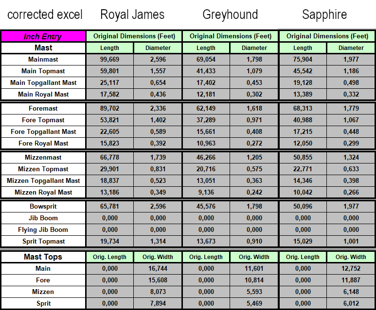
Hello, Because the Danny Vadas spreadsheet is so helpful, it deserves to be fixed for the period 1670 to 1710 that was mentioned by Allan (not Greg of course, as I wrote in a previous reply). Going over the formulas for that period I encountered the constant 8.2296 that was used in a comparison with a value expressed in feet. Now 8.2296 is 27 feet in metres and that is strange because mixing feet and metres can never give you a correct result. The subsequent addition or subtraction to the mast length in feet also used the constant in metres. That can explain why the results are judged way-off by the experts here on this forum. So, lets fix that and check if the results are more in line with expected dimensions. To do that I need some data the enter in the spreadsheet. A Wikipedia search delivered me the following data for 3 ships in that period to cover all cases that need to be handled in the spreadsheet (beam > 27 ft, < 27 ft and = 27 ft). These are the selected ships: The Royal James will be used to check the case ‘beam > 27 ft’, the Greyhound for case ‘beam < 27 ft’ and for Sapphire I will cheat and set the Beam to 27 feet to check the last case. These are the results from the original uncorrected spreadsheet: And these are the results from the corrected spreadsheet (except sprit topmast diameter, see later): I have no data on the mast dimensions of the 3 ships I used as a test but if someone here on MSW can evaluate these figures, I like to hear your comments. The original spreadsheet did produce the correct mast length if you set the ‘Metric Entry?’ input to ‘Yes’, and you entered all values in metres. The mast diameters are however always a little under the correct value, as I did explain earlier in this thread (see #26). Another issue I see for ships of the time period 1627 to 1719, is the diameter of the sprit topmast. According Lees, it should be in relation to the sprit topmast length but the formula in the original spreadsheet references the AU column which has the fore topmast diameter. So that was also corrected. Here is the corrected spreadsheet: Masting and Rigging-DV-open-corrected-KA.xlsm I did not take a look at the tops, yards, stays and all the other ropes, so be careful and check if you can. Best regards, Kris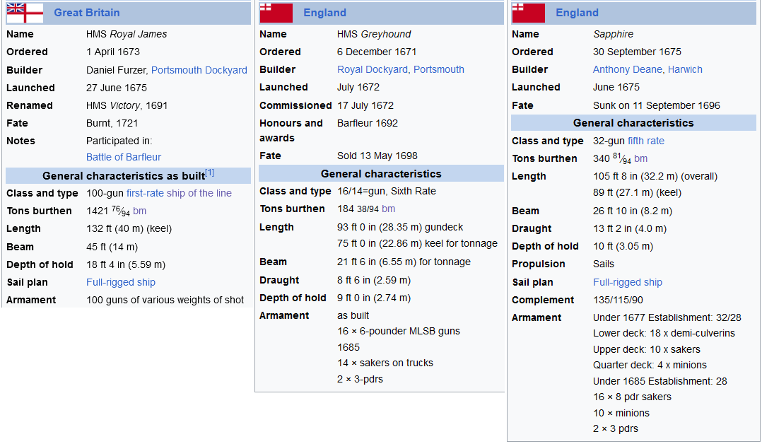

-
Period Scale Model Masting and Rigging Tables
Kris Avonts replied to DaveBaxt's topic in Masting, rigging and sails
As promised this morning, I can now provide you with an updated version of the Danny Vadas spreadsheet. Masting and Rigging-DV-open-corrected-KA.xlsm This version should produce correct diameters for all masts. Next I will also do a check on the 1670 - 1710 period that was warned about by Greg. Hopefully I can find some issue there and make a correction. It would be of great help if anyone could provide me with real data (beam, length of keel and depth of ship) of a ship from that period. best regards, Kris -
Period Scale Model Masting and Rigging Tables
Kris Avonts replied to DaveBaxt's topic in Masting, rigging and sails
Just an addition: do not use the above provided excel, it has no correction for the fore mast diameters. I will provide an update of the excel file soon. best regards, Kris -
Period Scale Model Masting and Rigging Tables
Kris Avonts replied to DaveBaxt's topic in Masting, rigging and sails
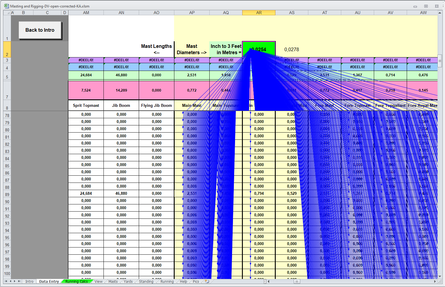
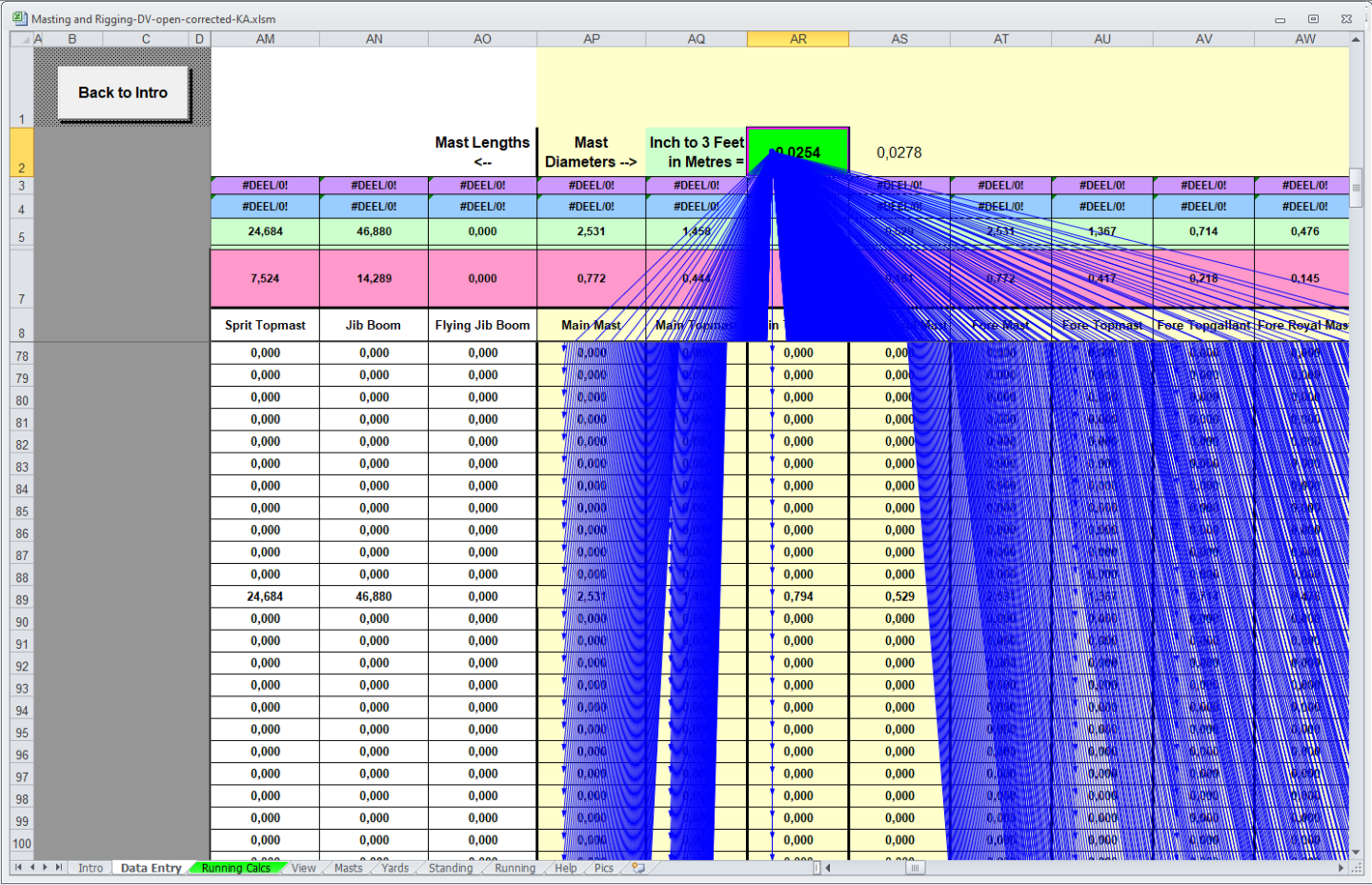
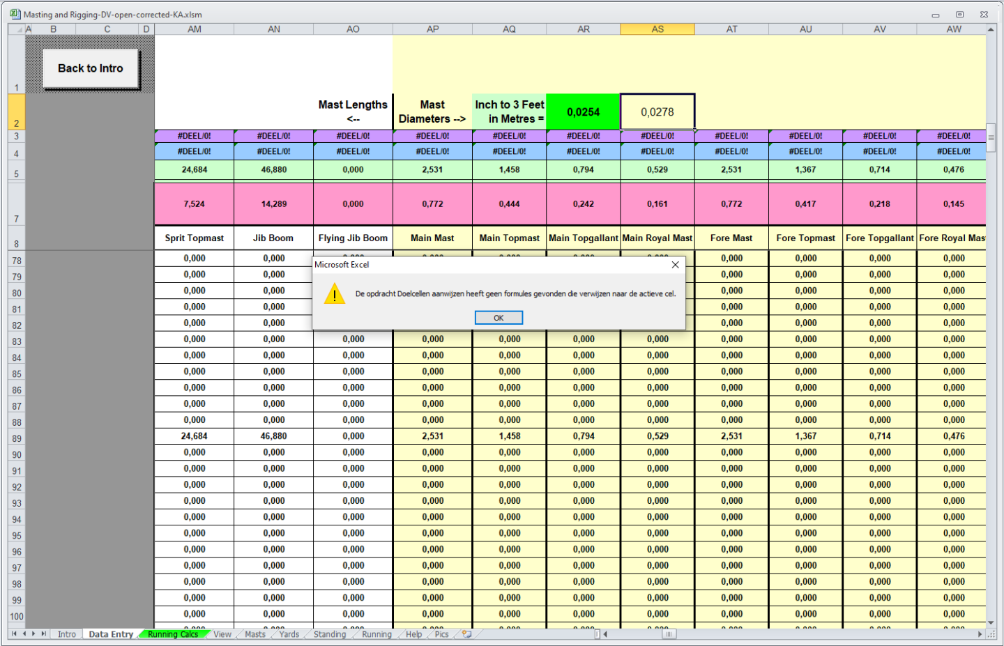
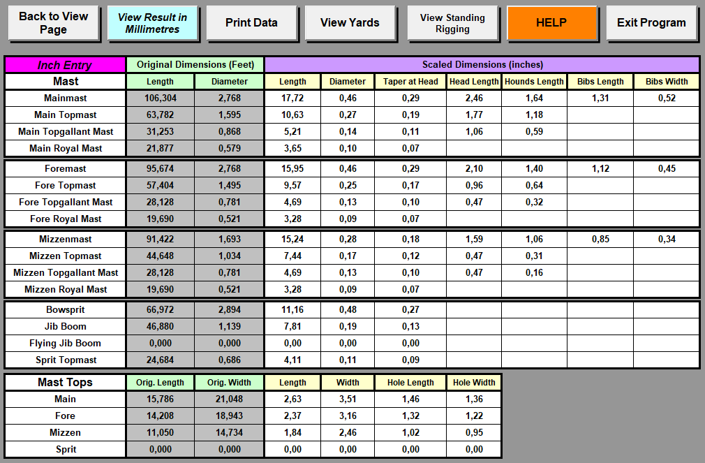
Hello, I found this topic while searching for mast and rope dimensions and I also already downloaded the spreadsheet made by Danny Vadas from the Articles Database. It's a well appreciated effort by Bob Fraser to provide this spreadsheet in an open form so one can look at the calculations done under the cover. That is why I’m reacting in this topic. I think that almost all masts diameter calculations are slightly under the value that results from the rules given in the book of James Lees. Let me explain a bit more in detail what I think is the problem. I entered a beam of 46.83 ft for a 3rd rate 74 gun ship in the 1769 section. According to Lees rules for that period ‘main mast to length of beam is 2.27’ and from that length, its diameter is ‘15/16 inch per 3 feet in length’. That gives me: 46.83 ft * 2.27 = 106.304 ft for head to heel length of the main mast and (15 / 16) * (106.304 / 3) = 33.22 in = 2.768 ft for its diameter. The results from the Danny Vadas spreadsheet are shown in the next screenshot. The mast length is spot on but the diameter is about 3 inch shorter. Then I looked at the spreadsheet formula for the diameter: ‘=(Z89*($AR$2*(15/16)))’. The Z89 is a cell with the calculated mast length value and $AR$2 refers to the cell AR2 that is preceded in the spreadsheet by the explanation ‘Inch to 3 Feet in Metres’ and has the value 0.0254. I expected this to be (1 / 3) * (1 / 12) = 0.0278, the combined division by 3 for the mast length and by 12 to get the result in feet like it is displayed in the Masts and Tops page. The strange thing is that cell AS2 has that constant 0.0278 but is not used. The next image shows a graph where the value of cell AR2 is used. So that is about everywhere. And this one is for the use of AS2. No graph could be shown because there are no formulas using that value (in Dutch in the image). To me it is now clear that we can only get the correct diameters (and all other proportions derived from the diameters) when we switch AR2 and AS2. That is what I have done in this excel sheet. Masting and Rigging-DV-open-corrected-KA.xlsm Because the error made in the original spreadsheet is less than 10%, I think it was overlooked. In any case, the Danny Vadas effort is a massive help to every modelship-builder. The Masts and Tops result page now looks like this. I hope this helps for all who are looking for masting and rigging dimensions. Best regards, Kris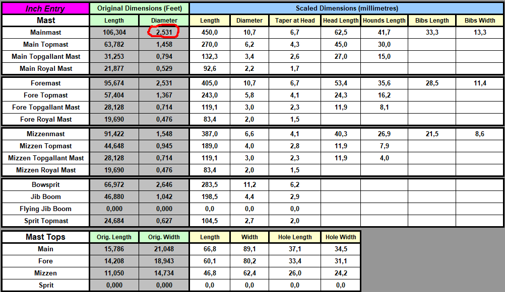
-
Byrnes Thickness Sander Advice
Kris Avonts replied to janet bode's topic in Modeling tools and Workshop Equipment
Hi Rafael9, After a little googling: And here is a link to this motor: https://www.batteryspace.com/dc-motor-heavy-duty-90v-dc-motor-40w-2000rpm.aspx If your data is correct it should be a match. Also the 2000 rpm is what is reported for the Byrnes sander with variable speed control. I hope this helps. best regards, Kris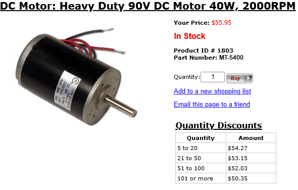
-
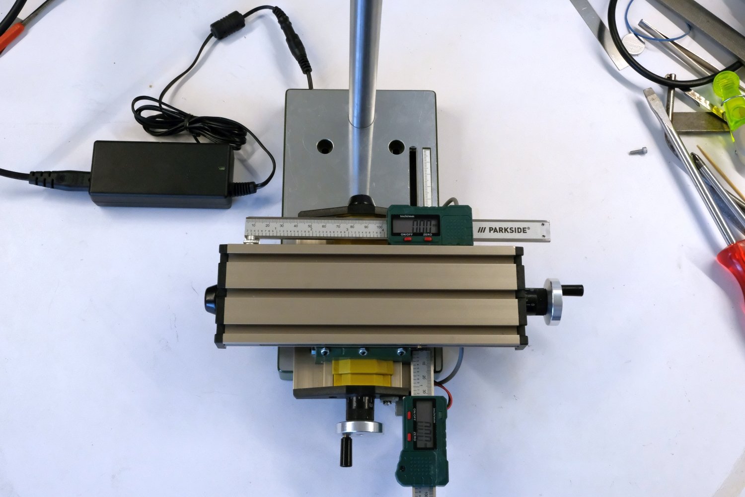
Adding a cheap DRO to a Proxxon XY-table
Kris Avonts replied to Kris Avonts's topic in Modeling tools and Workshop Equipment
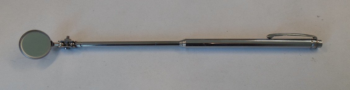
Hi Daniel, Sorry for this delayed reply to your question. Yes the zero button works as expected so you could use it the way you describe for each next 6 mils. But I would do it just by moving form 0 to 6 then 12, 18 and so on. You may have noticed that I removed the button 'metric/inch' since I never use inch measurements. I have found this DRO very useful when milling some larger cavities and also for making holes that need to be positioned at accurate places from one another. Next pictures show examples. The only negative issue I encountered so far is that with larger workpieces on the mill, it can be difficult to see the readout. In that case I use a small mirror but that of course gives a 'mirrored' image. I know there exist digital calipers that have an output with serial data (clock and data signal) so that you could capture it with a small microcontroller and direct the information to a better placed display. I checked but mine did not have such interface. best regards, Kris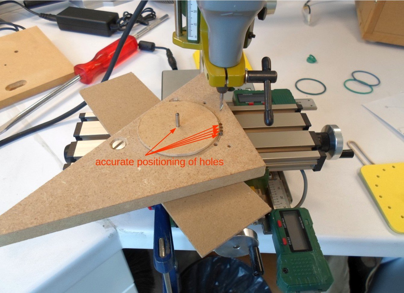
-
Adding a cheap DRO to a Proxxon XY-table
Kris Avonts replied to Kris Avonts's topic in Modeling tools and Workshop Equipment
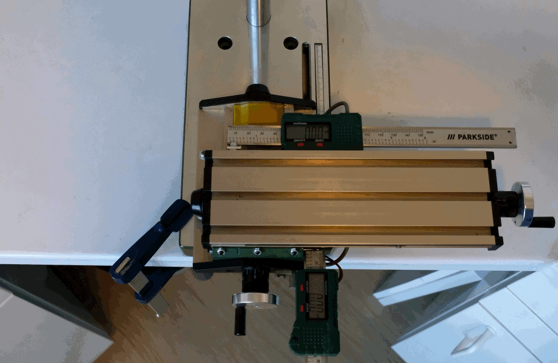
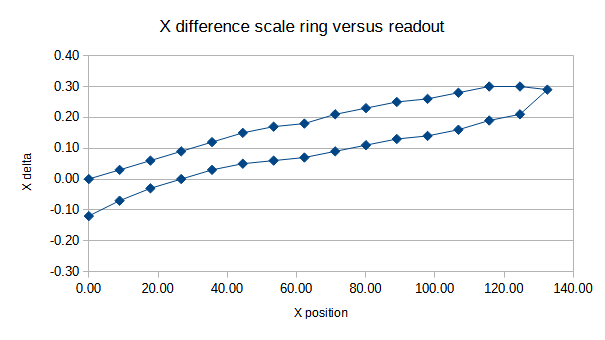
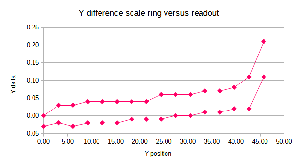
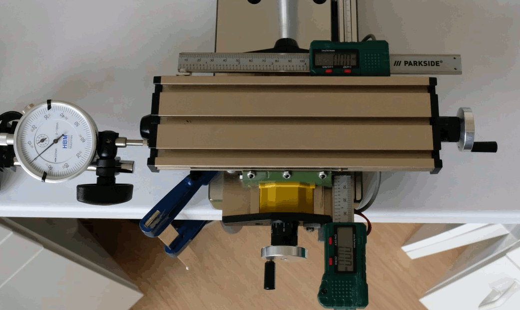
Hello, It’s time for some evaluation of this modified proxxon KT 70. As a test I made a setup to use the xy-table over its whole range with fixed steps in both x and y direction. In x it was 8.9 mm step and in y 3.1 mm. That way the whole range is covert with 15 steps. I use the scale ring to make the steps and note the DRO display values. Here you see the setup with a camera positioned to show the readings. This is how the table is stepped from bottom-right to top-left. I also did the inverse movement from top-left to bottom-right and again noted all displayed values. When entering the values in a spreadsheet and plotting things you get the following results. You can see that the curves are not ‘flat’ and that moving up and down follow a different path. Not flat means that the pitch of the xy-table is slightly off its nominal 1 mm. In the x direction we have about 0.3 mm error after 120 mm and that can be explained with a pitch being 0.9975 mm. For the y direction it is about the same result, a pitch of 0.9980. The different paths are a result from backlash, that is ‘play’ between nut and screw. For both x and y it is about 0.1 mm. I assume the DRO is correct and has no play. To be sure I also checked a small movement (8 mm) in the x direction somewhat in the middle of its range with a dial indicator. The result is shown next. The dial indicator and the readout give almost identical values. Ok, then I trust the DRO from now on. It is convenient because it keeps track of the millimetres already moved and it eliminates the backlash error. That is it for now, hope you liked it. Best regards, Kris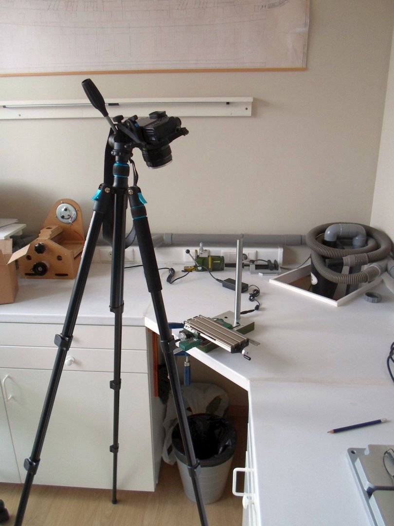
-
Adding a cheap DRO to a Proxxon XY-table
Kris Avonts replied to Kris Avonts's topic in Modeling tools and Workshop Equipment
Hi Mike, I understand your wish to position the display at a more convenient location. The display is an LCD type and requires a large amount op signals to display the information. The power and signal connection to the pcb is done with a 'zebra strip'. That is a kind of foam with alternating layers that are isolators and layers that conduct current. It is compressed between PCB and display, so no connector is used. On some PCB's of digital calipers you can find 2 interface signals intended for connection to a remote interface. These are clock and data signals. In combination with a small microcontroller board (e.g. Arduino) you can then decipher the data and put meaningful values on an extra display. This type of caliper had no such interface. So I had to use the display as it is positioned over the ruler. You are right, the Y-axis hand wheel is very close to the readout but it is possible to use it. I should have cut the extruding bulb before mounting. That gives about 5mm extra play. Now that it is already glued in place, I leave it as is. I'm glad you like my report on this modification. best regards, Kris -
Adding a cheap DRO to a Proxxon XY-table
Kris Avonts replied to Kris Avonts's topic in Modeling tools and Workshop Equipment
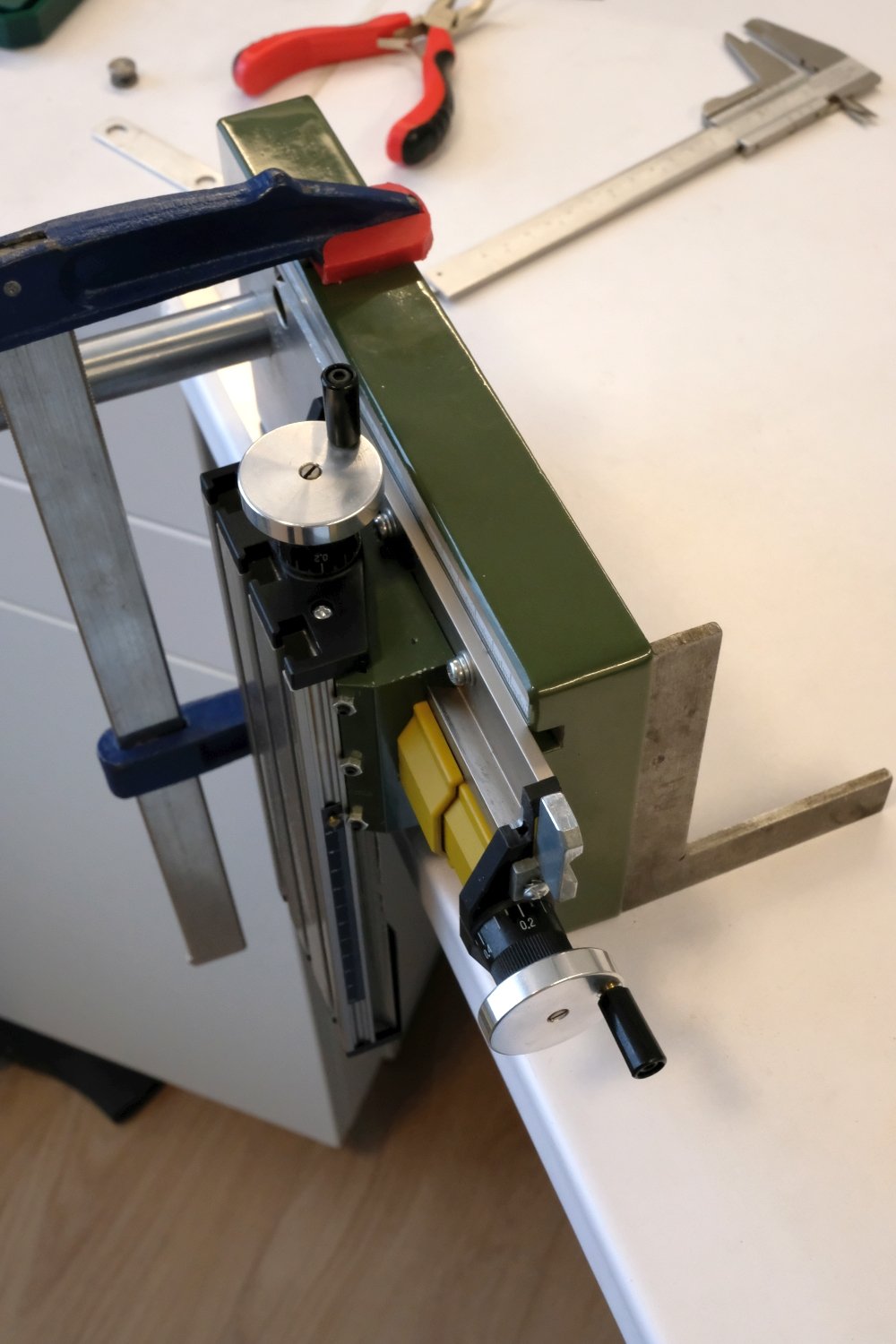
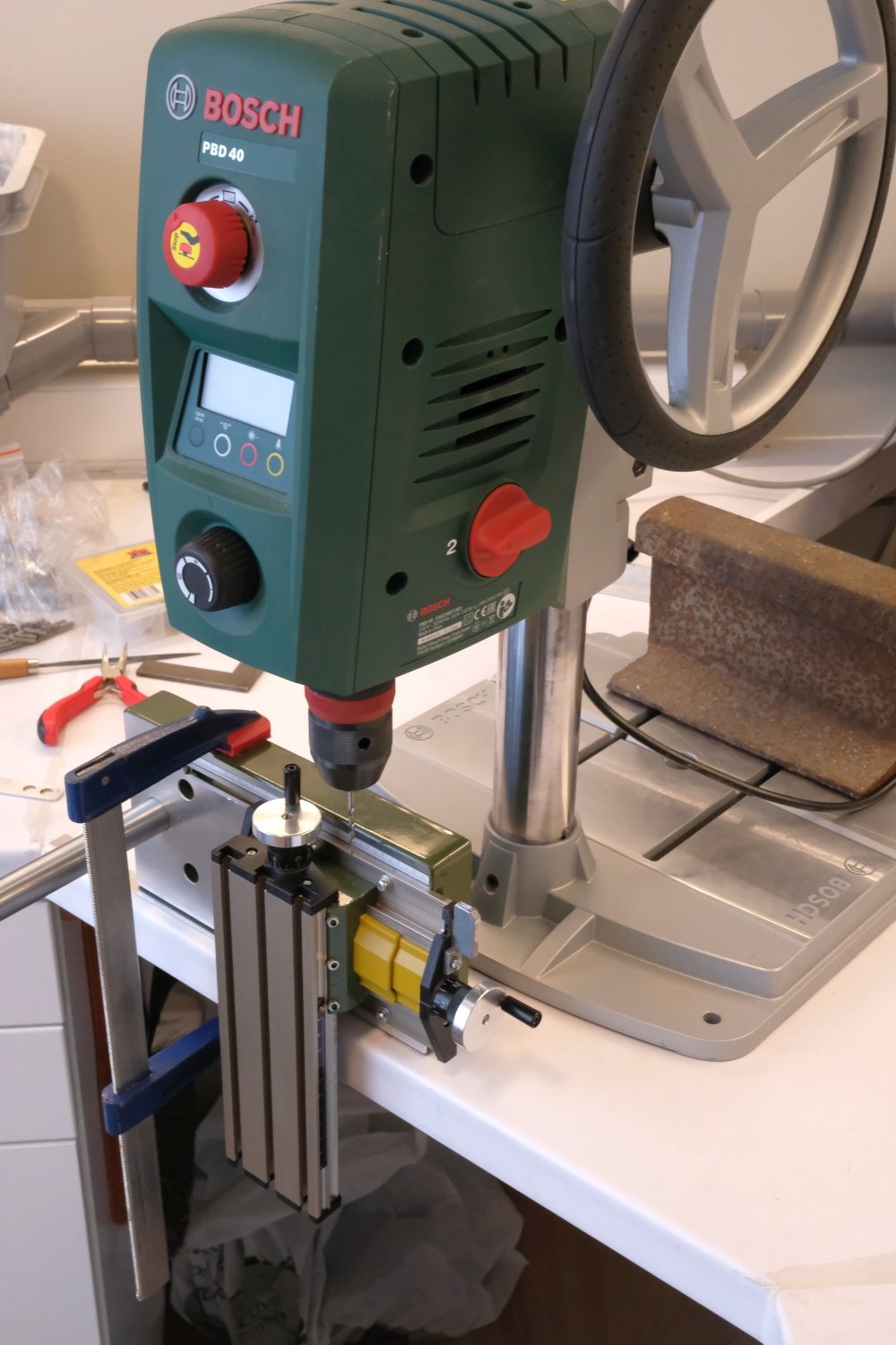
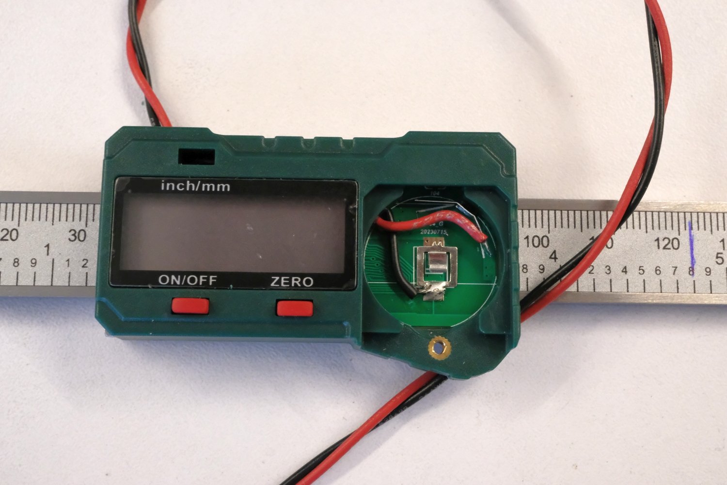
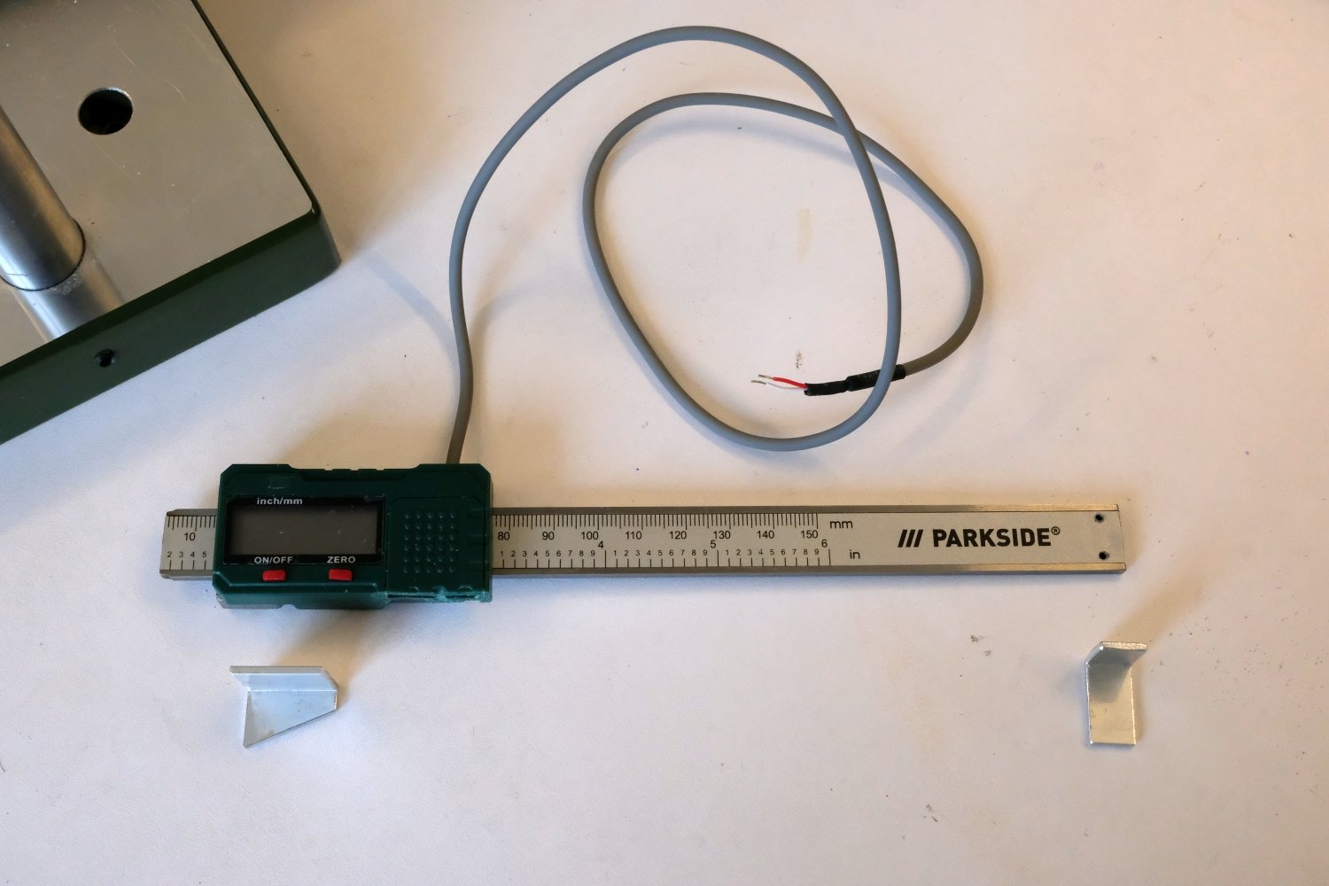
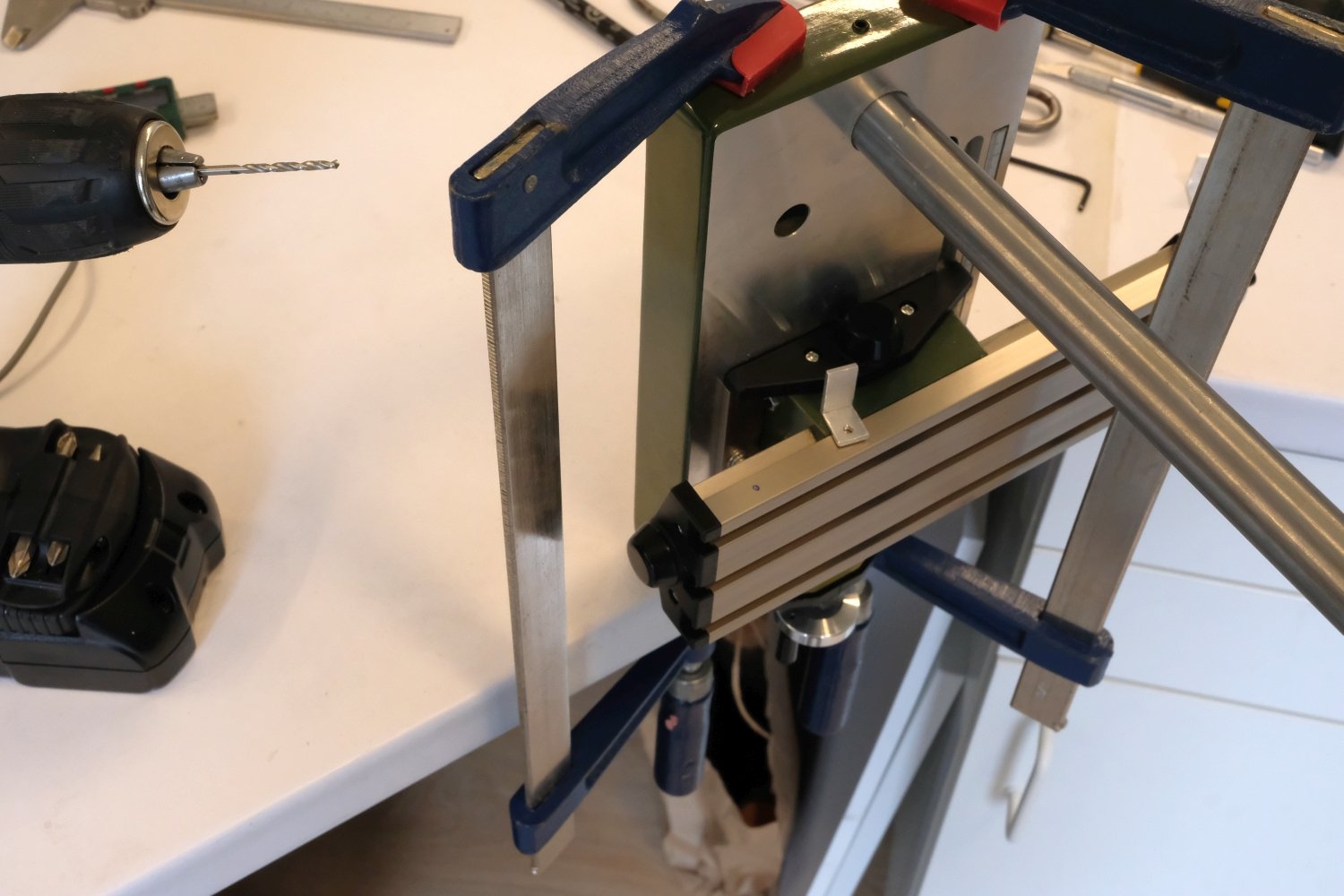
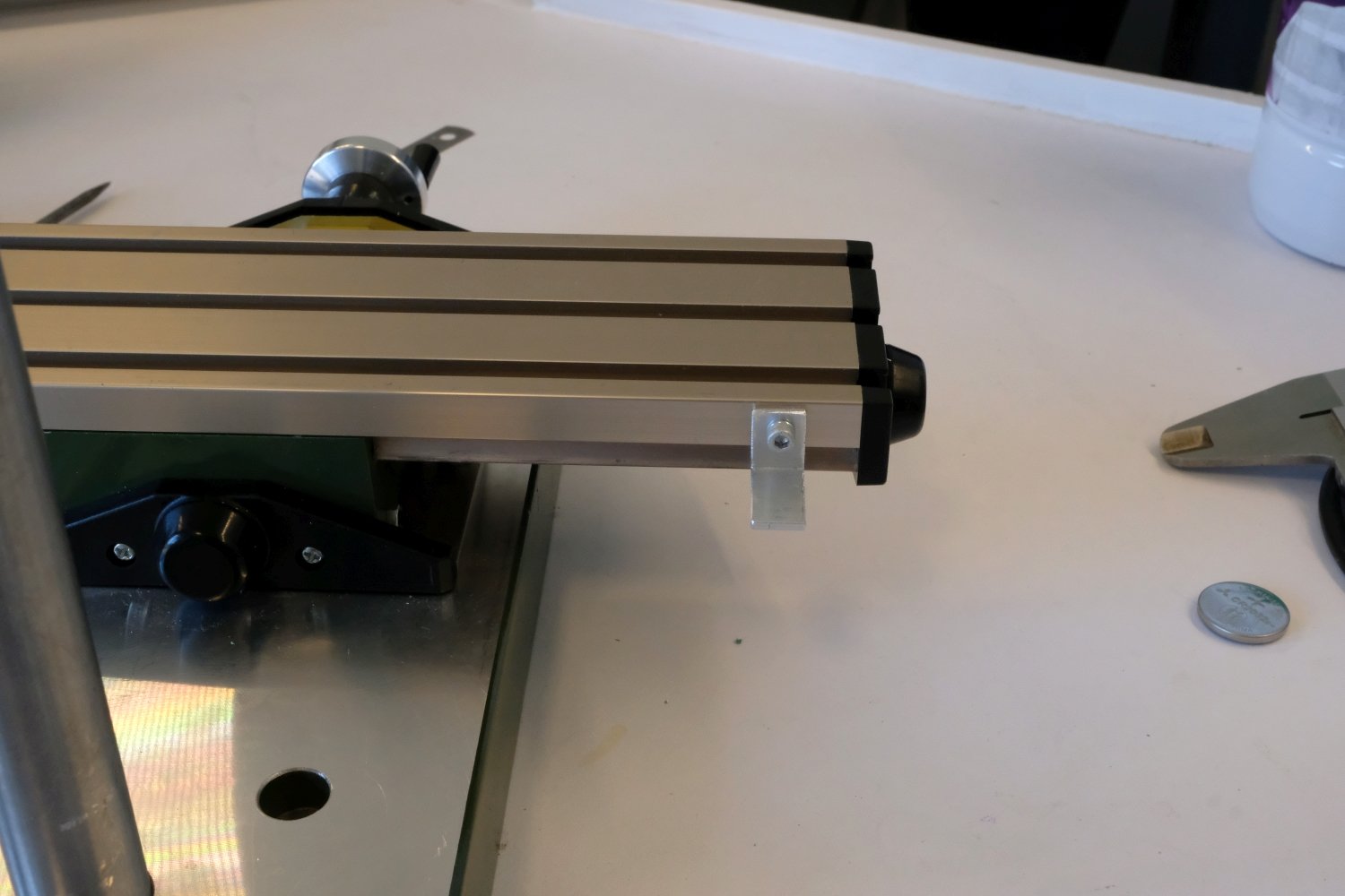
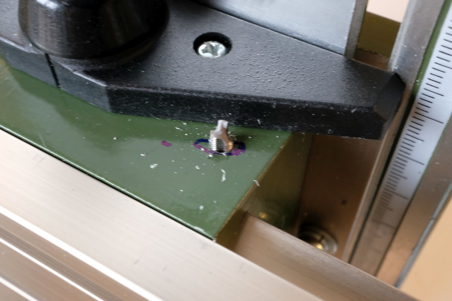
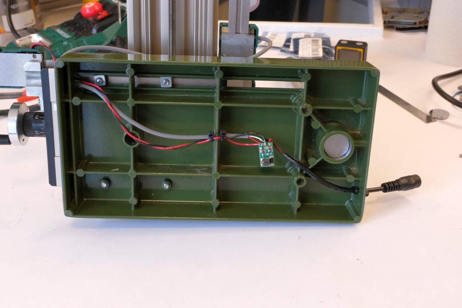
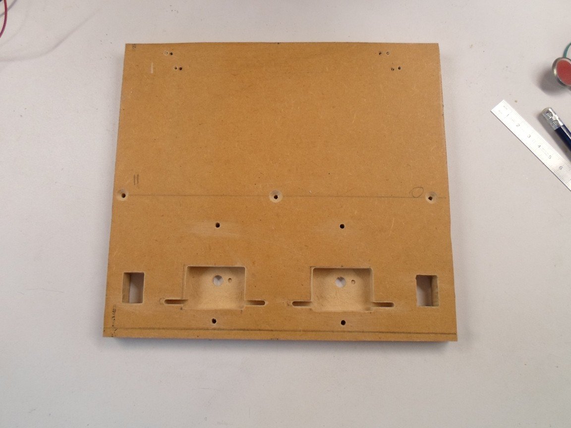
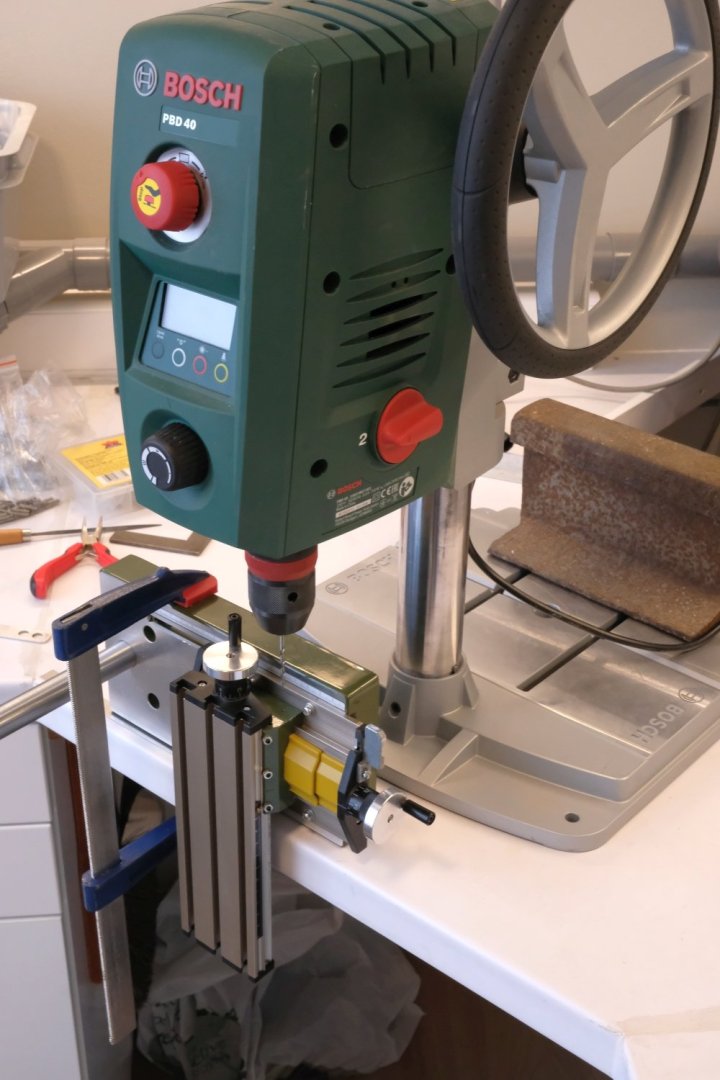
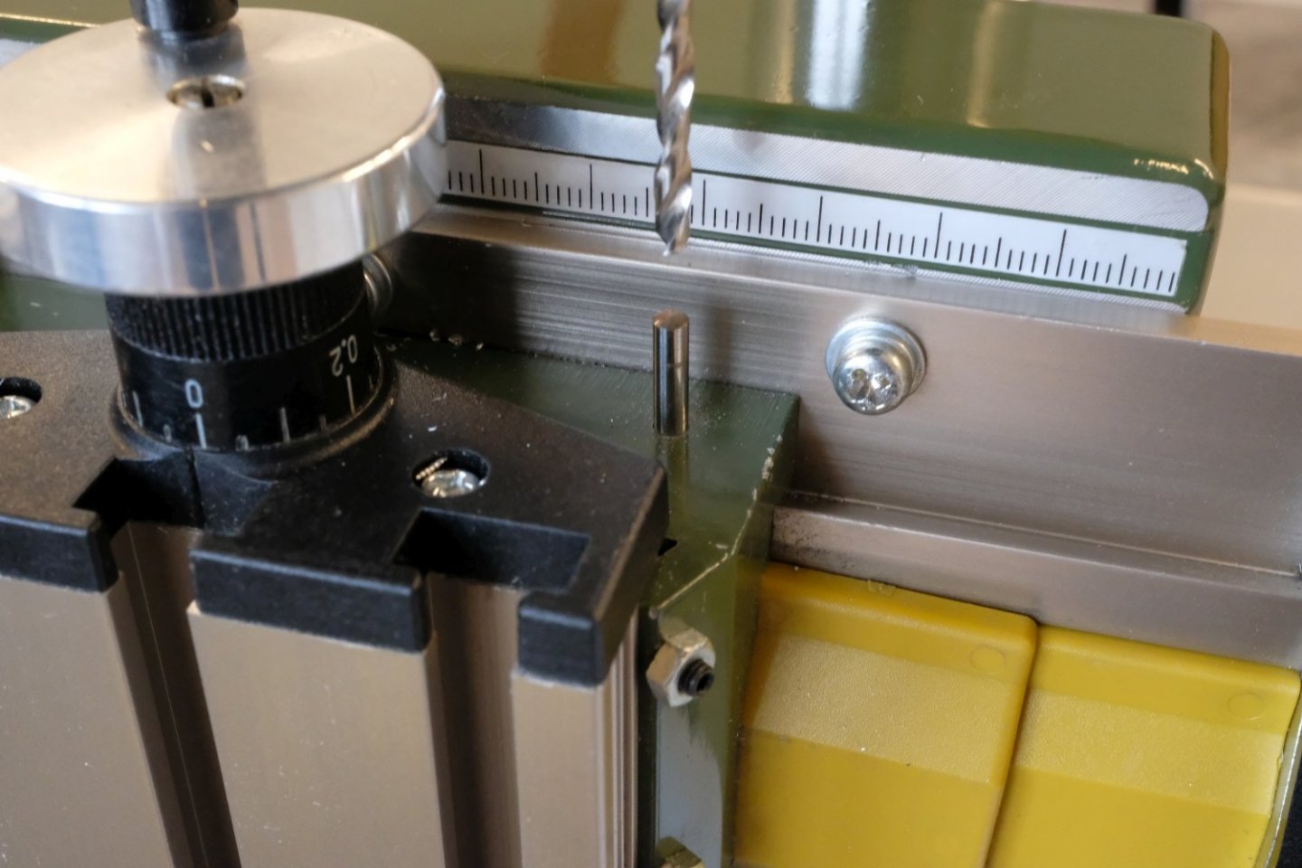
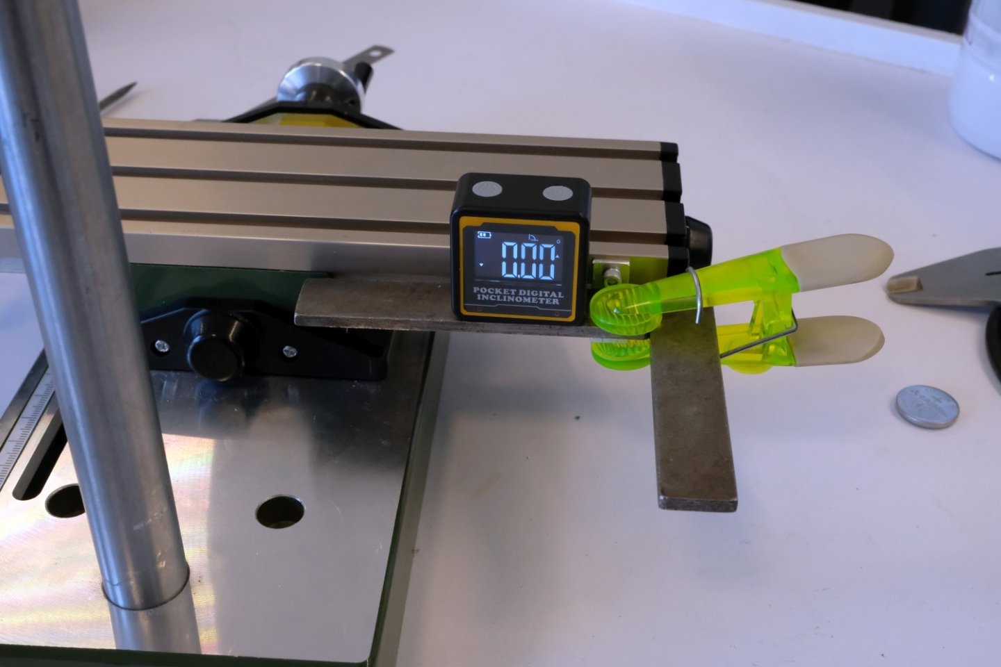
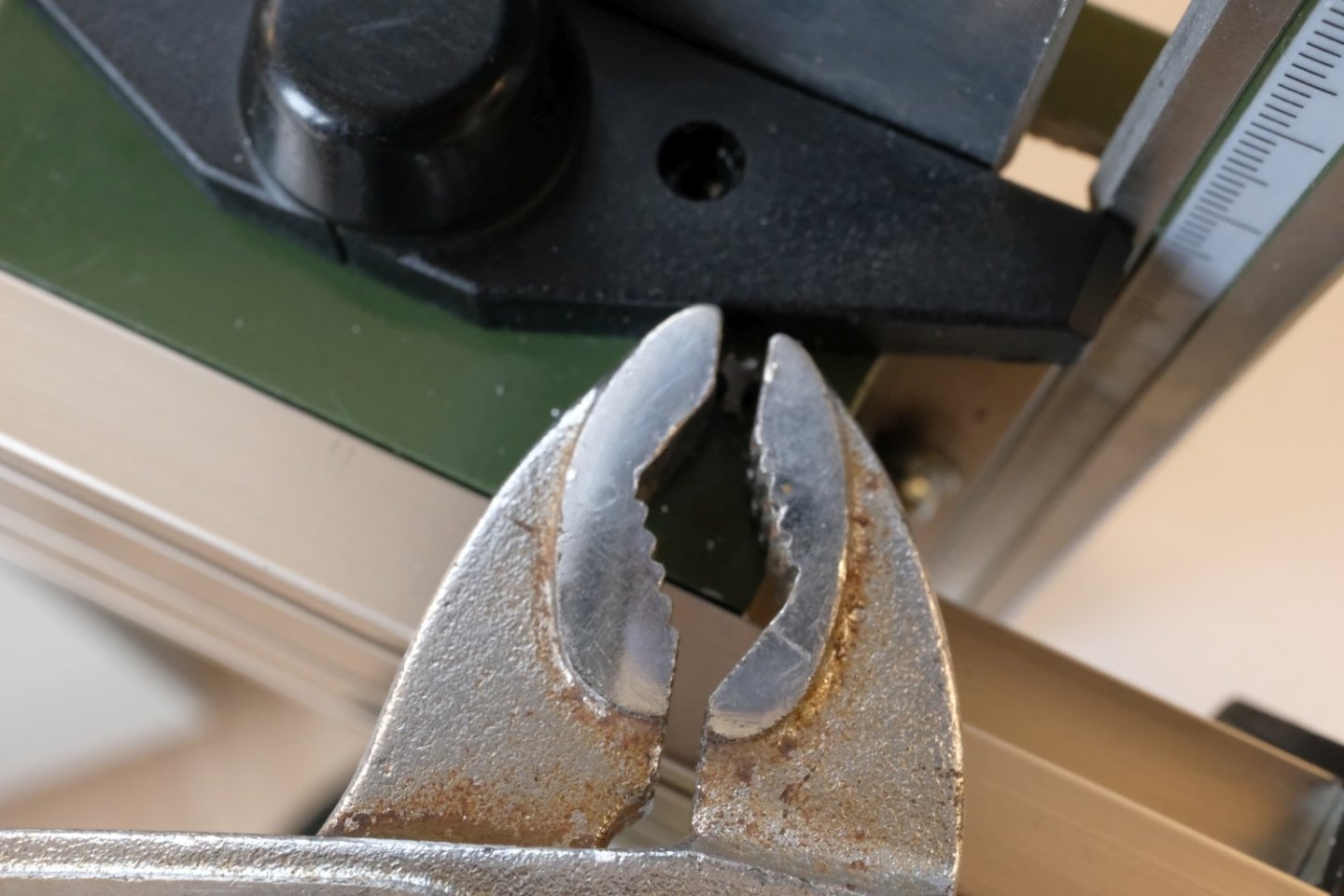
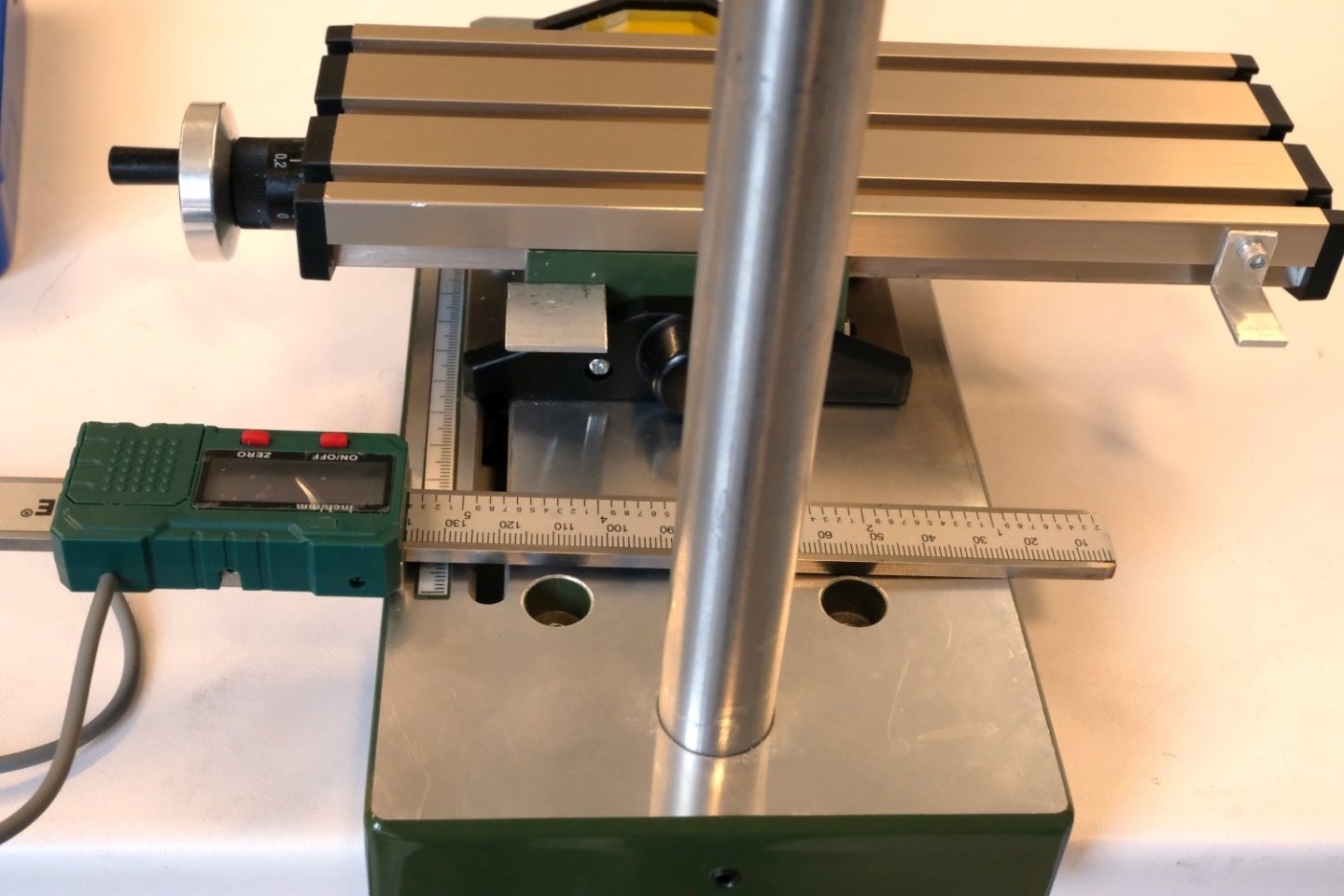
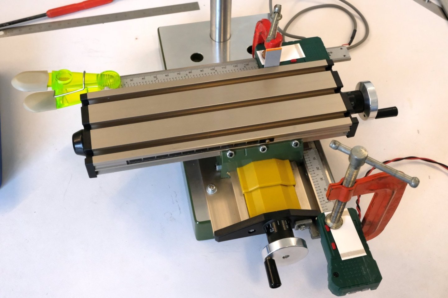
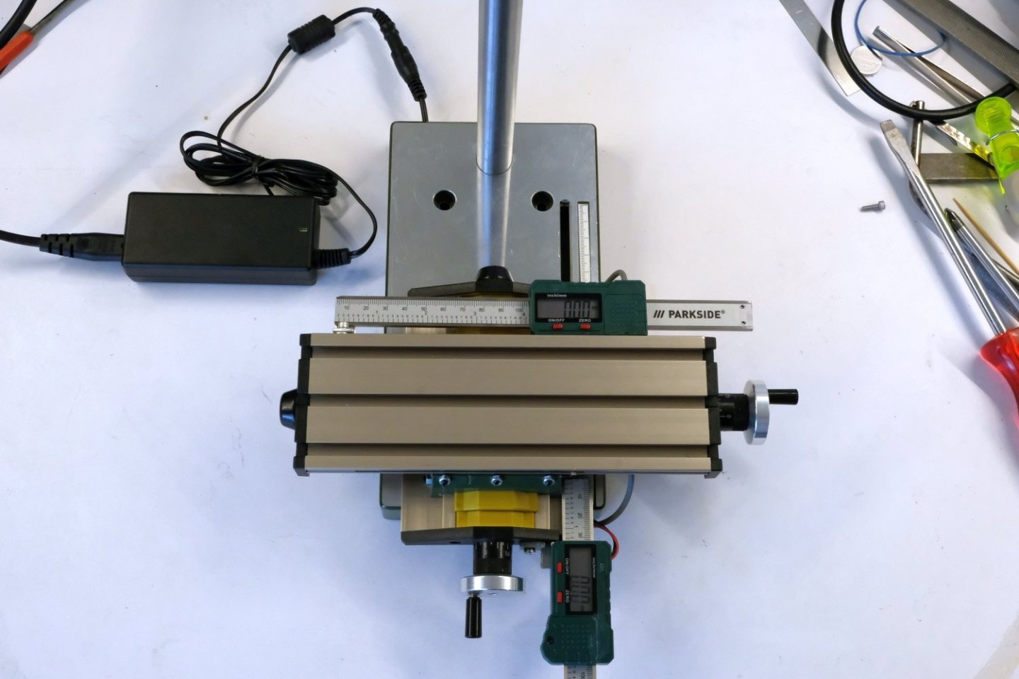
Hello, The next thing is to make a hole at the right of the cast aluminium block where the dowel pin will be inserted. I made a quite complex setup to drill that 3 mm hole as correct as possible. First job was the fixation of the xy-table to my work surface and checking its squareness (see the next picture). Then a rather unusual setup for my drill press where the base was turned to the back and using a counterweight to stabilize the drill press. That went well and the dowel pin fits with very little play. As a last adaption for the Y-readout, I soldered some wires to the metal battery clips in order to power the readout from a power supply. That should avoid battery replacements in the future. The X-DRO was made following the same principles but the ruler will be fixed to the mill table with a support instead of a pin. The next picture shows the readout already prepared with wiring, the ruler and both supports. You may notice that I cut away some plastic at the battery location to bring the readout as close as possible to the X-table side. Then the supports need to be fixed. The ruler support is attached to the mill table. With the threaded hole for the readout support I had bad luck. The M3 tap broke off but there was just enough of it sticking out so that I could remove it with a good forceps. The next picture shows the parts of the X-DRO ready for glueing to the mounted supports. Then with some metal epoxy glue all parts are glued, compressed and left for 24 hours to allow the epoxy to cure to its final strength. As a last addition I soldered the wiring to a small step down converter that will supply the 3V DC for both readouts. At the back is now a connector that mates with an old 12V DC supply of a laptop. Here is the finished KT 70 with its added DRO. Next time I will try to report on some test regarding the precision of this setup. Best regards, Kris


- 6 replies
-
- 10
-