


Captain Al
-
Posts
613 -
Joined
-
Last visited
Reputation Activity
-

 Captain Al got a reaction from Mr Whippy in MAYFLOWER by Captain Al - Model Shipways
Here's a few snapshots of work in process. For whatever they're worth. This is one instance where a picture does not tell 1000 words.
-
 Captain Al got a reaction from GrantGoodale in MAYFLOWER by Captain Al - Model Shipways
Here's a few snapshots of work in process. For whatever they're worth. This is one instance where a picture does not tell 1000 words.
-
 Captain Al got a reaction from Tigersteve in MAYFLOWER by Captain Al - Model Shipways
Just to say thanks to all those who've stayed aboard. Happy Easter Sunday. And Joel, can I blame it on my cheap tools?
-
Captain Al reacted to jbshan in MAYFLOWER by Captain Al - Model Shipways
Are you sure that aftmost port is still at 76 degs.? It looks to my eye to be about 75 degs. 30 min.
Just pulling your leg. One more fiddly bit to deal with, but ensconced in the 'no straight lines nor any right angles' challenge.
-
 Captain Al got a reaction from Waitoa in MAYFLOWER by Captain Al - Model Shipways
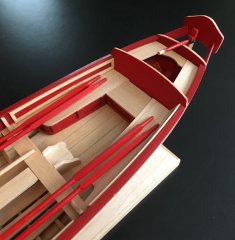
Gun Port Framing
Well I surely didn't expect the complexity that this process has turned out to entail. I think I put in 8 hours today and got 8 of the 16 frames in. Going into it I thought it was simply a process of cutting these little 1/4 inch frames and gluing them in. Not hardly. Here's why:
1. The two strips between which the frames sit are not directly on top of one another. Because of the curvature of the hull the top frame sits a mm or so more inboard. Chuck's instructions note that the frames need to be cut at an angle (turns out to be 76 degrees) in order for the top and bottom to seat under and over the two frames. Interesting since I don't know of any miter box that will cut a 76 degree angle.
2. Unless you've put the two strips on super perfectly (which I didn't apparently), the gap between them can vary from the 1/4 inch that the frames are supposed to fill. In my case there were variations in the gap from less than half a mm to a bit over half a mm. More or less a 1/64th to a 1/32nd of an inch. This meant that each of the frames had to be measured, marked and cut individually to both length and the angle.
3. There is nothing backing the two strips, so when a frame is pushed into its place, I had to hold a swizzle stick behind it so as not to push it too far in. The framing will faired to the hull later, but I wanted these frames to sit flush to the strips.
4. If I could get the frame to have a nice snug fit I used CA to hold it there. It there was any wiggle to the frame I used carpenters glue.
It would be hard to describe the process I finally developed for marking the 3/32 inch strip of wood at 76 degrees, cutting it, filing it, etc. Needless to say it was an interesting day. The pix tell a better story. I hope I've learned a few tricks (I must have cause the first frame took 4 hours and the last 7 only 4 more) that I'll apply tomorrow in doing the other side of the boat. The last photo shows where I got the 76 degree angle from.
-
 Captain Al got a reaction from BLACK VIKING in MAYFLOWER by Captain Al - Model Shipways
Gun Port Framing
Well I surely didn't expect the complexity that this process has turned out to entail. I think I put in 8 hours today and got 8 of the 16 frames in. Going into it I thought it was simply a process of cutting these little 1/4 inch frames and gluing them in. Not hardly. Here's why:
1. The two strips between which the frames sit are not directly on top of one another. Because of the curvature of the hull the top frame sits a mm or so more inboard. Chuck's instructions note that the frames need to be cut at an angle (turns out to be 76 degrees) in order for the top and bottom to seat under and over the two frames. Interesting since I don't know of any miter box that will cut a 76 degree angle.
2. Unless you've put the two strips on super perfectly (which I didn't apparently), the gap between them can vary from the 1/4 inch that the frames are supposed to fill. In my case there were variations in the gap from less than half a mm to a bit over half a mm. More or less a 1/64th to a 1/32nd of an inch. This meant that each of the frames had to be measured, marked and cut individually to both length and the angle.
3. There is nothing backing the two strips, so when a frame is pushed into its place, I had to hold a swizzle stick behind it so as not to push it too far in. The framing will faired to the hull later, but I wanted these frames to sit flush to the strips.
4. If I could get the frame to have a nice snug fit I used CA to hold it there. It there was any wiggle to the frame I used carpenters glue.
It would be hard to describe the process I finally developed for marking the 3/32 inch strip of wood at 76 degrees, cutting it, filing it, etc. Needless to say it was an interesting day. The pix tell a better story. I hope I've learned a few tricks (I must have cause the first frame took 4 hours and the last 7 only 4 more) that I'll apply tomorrow in doing the other side of the boat. The last photo shows where I got the 76 degree angle from.
-
Captain Al got a reaction from Tigersteve in MAYFLOWER by Captain Al - Model Shipways
Got started on the dummy cannon strips and the cannon port framing. Turned out to be surprisingly intricate work. Some of the little rebate notches to hold the upper and lower framing strips needed to be faired. Again, laser cuts only do 90 degrees and there is a definite curve to these strips. Not a lot of holding surface to these little notches either, and not a very good position to use strong clamps. So I decided to use CA glue on the first and last bulkhead as well as a dab of it on the middle one. The other 4 I marked and applied PVA to both the notch and the strip. This is one place where spot gluing is called for. Applied the PVA first, then when ready, dab on the CA gel and press the strip into place. Its nice to be working with a size model where my hand can span just about the whole work area, allowing me to apply pressure to the 3 CA spots. When the CA set up I added some clamps to the other 4 spots, though they were all sitting pretty snug in their notches.
Came time for the last strip and it just wouldn't test fit well. It all looked pretty well faired but I couldn't get the strip to sit comfortably in all the bulkhead notches at the same time. I soaked and bent the strip onto a "jig" and in the morning I hope it'll sit better.
-
Captain Al reacted to RichieG in Mayflower by RichieG - Model Shipways MS2020
Al, good points, thanks. I don't have and sanding lacquer (same as sanding sealer?), but I could probably acquire some.
The planks are pretty soft, and I could try just pushing the pencil point in. I might get more variable sized holes, but we shall see.
I think the trick to avoiding the blotchiness is to sand off the extra filler well. It's kind of invisible in this case, so you have to look at it under the light at an angle to see it.
The instructions say to use an eyebolt, and just bend the eye down to simulate a handle, so I'm doing that. The hinges are paper painted black with a small wire for the hinge pin. Note: in the photos, the hinges are just rectangular. In the plans, they have a taper with a sort of bulb on the end (which I like) so I'll try to emulate the design on the plans.
-
Captain Al got a reaction from Tigersteve in MAYFLOWER by Captain Al - Model Shipways
Yes, the bow fillers have to be flush and if there was a mistake made with the reference marks it was in my favor. For whatever reason they lined up where they did when the tops were flush and I accepted the reference marks as confirmation that they were on right. As much as I love the instruction booklet, the pictures can be deceiving. Its often hard to tell when two pieces are flush. As for the wooden piece -- following a message I got from Chuck (question was why such a large eyebolt; answer was anything much smaller would be really hard to get hold of when there was lots of other things going on in and around the recessed filler) not to mention your mention that the holes were disoriented, I changed my mind and went with the eyebolt exactly how Chuck describes making it. I am going to post some pix and words about that and my work yesterday on the stern. But that'll have to wait til after breakfast. Getting a late start today.
-
 Captain Al got a reaction from Captain Poison in MAYFLOWER by Captain Al - Model Shipways
Going to try Danny's way of inserting pics into my text. Hope it works.....
Part YY's bottom edge forms part of the counter which is a finely curved section that will be planked over shortly. These pix show this curve in the frames and how the part YY overhangs it and needs some radical shaping.
I
-
Captain Al got a reaction from Tigersteve in MAYFLOWER by Captain Al - Model Shipways
I believe I solved the problem of how to make the curve of the counter flow nicely into the YY stern piece. In the process I rekindled my interest in moving to scratch building.
Problem I had was I didn't know how much wood to take off the YY piece in order to make a smooth curving planking surface. If it was going to be a lot of wood I preferred to do most of the work off the boat. So how to know? I decided to make myself a spare part out of the remains of the template plywood. Hint (probably everyone knows this) don't throw that stuff away -- it comes in very handy many times). So I cut the piece to shape on the Dremel scroll saw and "perfected" the edges with the disk sander. Placing the new experimental piece in place with the boat upside down it came clear that the curve could flatten out alot when it hit the stern piece; meaning a whole lot less wood to take off. I also realized I would be dealing with 1/8th x 1/16th inch planking here which is considerably smaller than the 1.5 x 5 mm planking I was used to using on my last build. Its interesting to find how much my thinking has to change having moved to a much smaller scale model.
So I beveled this spare piece and and laid some of the planking over it. Yes. I think it works quite well. So well in fact that I started thinking about using my newly made piece in place of the kit piece. No reason really other than I could avoid doing the beveling over again. And, my hour's work would not have been in vain. But to do so I'd have to cut out the 3 windows. Decided to go for it. Drilled 1/4" holes (in three steps) in the center of the window spaces (copied from the real piece) and began filing into rectangles. I've finished just the middle window and that alone has taken 2 hours. So tomorrow I'll decide whether to bevel the kit's piece and use it, or continue to finish my spare piece. I'll probably do the kit's piece.
The day's work was quite a lot of fun and like I said above, showed me that with patience I could probably do a credible job of scratch building a simple vessel.
-
 Captain Al got a reaction from RichieG in Mayflower by RichieG - Model Shipways MS2020
Lookin good. I agree that at this scale its hard to get trenails to look realistically small. I don't know how soft this planking is but I found on Bounty that the sharpened pencil made a good enough indentation -- enough to avoid drilling all the holes. And I'm just guessing, but I would bet that the wood filler is unnecessary if you paint the whole wall with sanding lacquer; maybe but not necessarily two coats. That would fill the holes without all blotch marks. You might also consider doing the staining first, then the trenailing and then the coat of lacquer. Will you be putting rings or something on the doors? A small eyebolt with a ring hung in it makes a good looking door knob (of sorts).
-
Captain Al got a reaction from Mr Whippy in MAYFLOWER by Captain Al - Model Shipways
All the bulkheads are now glued in and the fillers (bow, main, mizzen and foremast) as well. All except for the two foremast fillers on port side which are a story in themselves.
Putting these in was pretty straightforward and easy. Not much explanation needed other than to get them oriented correctly so the top edges match the slope of the bulkhead former. There is a slant to the BF which will create the slope of the decks from the bow and stern towards the center. Its not a huge angle but its possible to ignore it and think that the mismatch between the fillers' shape and the BF is just something that can be sanded down later. I guess it could. Probably wouldn't be any harm done; just alot of work and dust. So here's my work for today, starting with the completed bulkheads and running through the several fillers.
-
 Captain Al got a reaction from jbshan in Mayflower by RichieG - Model Shipways MS2020
Lookin good. I agree that at this scale its hard to get trenails to look realistically small. I don't know how soft this planking is but I found on Bounty that the sharpened pencil made a good enough indentation -- enough to avoid drilling all the holes. And I'm just guessing, but I would bet that the wood filler is unnecessary if you paint the whole wall with sanding lacquer; maybe but not necessarily two coats. That would fill the holes without all blotch marks. You might also consider doing the staining first, then the trenailing and then the coat of lacquer. Will you be putting rings or something on the doors? A small eyebolt with a ring hung in it makes a good looking door knob (of sorts).
-
Captain Al got a reaction from Tigersteve in Mayflower by RichieG - Model Shipways MS2020
Lookin good. I agree that at this scale its hard to get trenails to look realistically small. I don't know how soft this planking is but I found on Bounty that the sharpened pencil made a good enough indentation -- enough to avoid drilling all the holes. And I'm just guessing, but I would bet that the wood filler is unnecessary if you paint the whole wall with sanding lacquer; maybe but not necessarily two coats. That would fill the holes without all blotch marks. You might also consider doing the staining first, then the trenailing and then the coat of lacquer. Will you be putting rings or something on the doors? A small eyebolt with a ring hung in it makes a good looking door knob (of sorts).
-
Captain Al got a reaction from RichieG in Mayflower by RichieG - Model Shipways MS2020
I've gotten all my bulkheads cut out and sanded down (leaving plenty of char for fairing). I will be test fitting and doing a bit of sanding today and then tomorrow I am going to put the rabbet strip on. So I want to be sure I'm understanding what you were saying above about that. If I understood it you had a problem cause when you tapered the keel you tapered all the way into the rabbet. I'm wondering why this was a problem since Chuck's instructions specifically say that the tapering to 3/32 means you will reduce the thickness of the rabbet as well. And that makes sense since the rabbet starts out being 1/8 or 4/32. So 1/32 will come off the rabbet (1/64th " from each side of it hopefully). I don't see any harm in doing it the alternative way you mention, but you are then going to be dealing with a sliver of wood 3/32". Do you have such a piece already or is your plan to glue on the 1/8th inch piece and sand off the overlap? That seems like getting right back to where you started. And if you have the 1/8th rabbet already on when you do the tapering, it gives you a reference to get both sides even and then just a bit more off the rabbet.
I've practiced a bit on tapering a corner of one of the used templates from the bulkheads and while its not really a hard thing to do it is easy to take too much off one side or the other ending up with the right size but looking unbalanced. I'm going to see if I can make a little V shaped sanding tool to make sure I do the sanding evenly on both sides. I'll cut a V (with a flat bottom) into a little sanding block with the same width at the top and bottom as the keel needs to end up. Then I'll glue sandpaper to the inside of the notch and place it over the keel. As I stroke back and forth it should take just the right amount off as it pushes deeper into the keel. Maybe. Maybe not. I'll let you know if it works. Probably just easier to do a bit at a time turning the keel over and over as you go.
-
Captain Al got a reaction from RichieG in Mayflower by RichieG - Model Shipways MS2020
Hey Richie, that is a downer. I feel really bad for you seeing as my kit came so well. Do you have a scroll saw and would you attempt to cut your own PF (ha ha I thought you told me it was being called the 'profile former' so I went with PF. Should I switch to BF? Naw, from your pov now it should be BS)? I would do that for you if you say its worth while.
Next build? Scratch build from swizzle sticks. Avoids all hassles. Only down side is you have to drink way too much coffee to finish the build.
-
Captain Al got a reaction from Tigersteve in Mayflower by RichieG - Model Shipways MS2020
Hey Richie, that is a downer. I feel really bad for you seeing as my kit came so well. Do you have a scroll saw and would you attempt to cut your own PF (ha ha I thought you told me it was being called the 'profile former' so I went with PF. Should I switch to BF? Naw, from your pov now it should be BS)? I would do that for you if you say its worth while.
Next build? Scratch build from swizzle sticks. Avoids all hassles. Only down side is you have to drink way too much coffee to finish the build.
-
Captain Al got a reaction from Waitoa in MAYFLOWER by Captain Al - Model Shipways
So as I was saying. I wasn't sure exactly how the bulkheads should be positioned. Should the tops be flush? Should the bottoms of the two grooves butt up to each other? Or should the lowest part of the bulkhead (where it narrows to just the width of the PF) just be on the bearding line? There were reasons to think any of those might be the best, but in the end I decided to make the tops flush and I used shims to make that happen. In one case where the bulkhead was higher than the PF I filed the notch a bit deeper (filed both the PF notch and the bulkhead notch). Here's a shot of the shims. I used some .6mm deck planking from my last build and for the deepest one I used a bit of a Starbuck's swizzle stick. These just continue to come in handy. I'm thinking of building a scratch build completely out of swizzle sticks.
-
Captain Al got a reaction from Mr Whippy in MAYFLOWER by Captain Al - Model Shipways
Continuing on where the last reply left off -- I've not yet learned how to insert a photo and then continue with the text. All my pix seem to end up at the bottom of the reply.
I mentioned in my first comments that the PF was perfectly flat; no warpage. So the test fitting did not have any issues with that sort of thing. It was all a matter of sanding the notches a bit to get the pieces to slide into each other and still be snug. I found that sometimes it also helps to sand the surface of the bulkhead on both sides. This tiny bit of wood removal is usually enough to get the open notch to slide down the face of the bulkhead. Nerve racking when in the process you can't get the bulkhead out. Don't want to break that keel in half. Finger pressure is the only answer. Hands acting like one of those tools auto mechanics use to pull out gears and bearings.
Now my big question was: Are you supposed to slide the two grooves together ALL THE WAY so the bottoms of the notches bang up against each other? Because if you do, I was seeing that in some cases the tops of the bulkheads stood proud of the top edge of the PF, and sometimes the tops ended up lower than the PF. I sensed that it is important that the tops all lie flush. Here's a pic or two to illustrate. Then I have to run to breakfast and get the day underway. But, like McArthur, I shall return. Note that photograph seems to magnify the problem. In the first pic below it looks like the bulkhead is sitting a half inch below the PF. In fact, the worst case was 1.5 mm.
-
Captain Al got a reaction from Mr Whippy in MAYFLOWER by Captain Al - Model Shipways
SUNDAY MORNING UPDATE 4-9-17
Nice time to sit quietly, sip a steaming latte and contemplate and report on what's been accomplished over the weekend. I'm now in the process of gluing in the 14 bulkheads (completed 8 of them and hope to do the final 6 before going to bed tonight). Here's a brief run down on how the process has gone....
To begin with, the first step is always popping the parts out of their templates. To me this is the most onorous, boring, time consuming and even fatiguing process there is in kit building. For the PF and bulkheads its always the thickest plywood (in this case 3/8ths) and I've always got the fear of snapping one of these off. I use a #11 blade which I know to be quite sharp (just purchased 100 new ones from MicroMark for $21) but my handle is just an aluminium tube that I've had for 40 years. Probably a good handle would reduce the fatigue. So this step took quite a while but in the end, with new found patience, I broke nothing and got all the pieces removed.
Next was to remove the 'char.' I noted to RichieG that all the pieces and the template itself looked like it had gone through the London Fire. Seriously discolored. Not just the cut edges but even the flat surfaces (not however the one good side of the plywood with reference marks). So began the sanding off of char process. Question then became how much to sand off? I've learned from the past that I can get pretty aggressive and actually take off so much wood that I later have to compensate for it. I wanted to be sure I left the shape and dimensions of these bulkheads exactly as cut. Its important to visualize that the top edge of the bulkhead becomes the cross beams for each of the decks.
So they have a slight concave shape that needs to be maintained. I decided after consultation that removing char does nothing more than prep the wood for gluing (I'll stand corrected if this conclusion is wrong), so it only needs to rough up any "shine" or slick areas -- in other words, open up the pores so glue can adhere better. No need to sand darkened areas down to new wood. That would be far too much.
TEST FITTINGS
So now my PF and bulkheads are ready for test fitting. I've never thought it worthwhile to invest in one of those thingies that hold the PF (or false keel) in place and purport to guarantee that the bulkheads are squared up. Instead I use the vise that I have from my full size Delta 15" drill press. It can be seen in some of the pix I'll attach.
-
 Captain Al got a reaction from Grendel in MAYFLOWER by Captain Al - Model Shipways
Good to have you all aboard.
-
Captain Al got a reaction from Tigersteve in MAYFLOWER by Captain Al - Model Shipways
Good to have you all aboard.
-
Captain Al got a reaction from Tigersteve in MAYFLOWER by Captain Al - Model Shipways
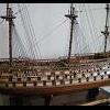
This is the official start of my Mayflower build log though I have been posting pictures and comments for about a week on RichieG's log. Thanks RG for loaning me the space.
I'll dispense with all of the photos of the box and its contents. This is the Modelshipways kit with the great 52 page instruction booklet by Chuck Passaro. Thank you Chuck for including this...its wonderful and actually was the deciding factor in my purchasing this kit. The booklet can be viewed on-line before buying the kit for anyone interested. http://www.historicships.com/TALLSHIPS/Model Shipways/Mayflower/MS2020-Mayflower-Instructions.pdf
The kit arrived in 2 days even though I paid for 7-10 day shipping. Nice people at Model Shipways.
I did a complete inventory of the parts and wood supply and was amazed at what accuracy everything was supplied. If there are supposed to be 80 pieces of planking, there are 80 pieces. Not 79 or 81, but 80. Same for stuff like cleats and rings and pins. The only thing I didn't count was tacks. I trust there will be enough. Now it remains to be seen if MS has allowed for some breakage and loss overboard. We shall see.
My only disappointment is in the metal platforms or "crows nests" that are supplied pre-cast. They're a bit tacky. But MS probably knows this and the instructions detail how to scratch build your own from wood. Which I plan to do. Same for a capstan.
Its going to be interesting working at 1:78 scale and in fractions. My only previous build, Bounty, was 1:48 and measured in metrics which I got very used to and find so much easier to use at these small sizes. Whatever happened to Jimmy Carter's plan to put the country on the metric system. Was supposed to happen within a decade. I guess we Americans don't give up our old ways easily.
There are 4 sheets of plans which, along with the booklet, seem detailed enough. Without the booklet I would say they would be not quite sufficient.
My only worry on receiving the kit was whether or not the profile former (used to be called the false keel), which from here on I am going to abbreviate as PF, would be warped. My Bounty false keel was a bit warped and I stubbornly pushed on with the build without attempting to get a replacement from Artesiana Latina. I think if I had waited I would still be waiting and that was 3 1/2 years ago. I know RichieG needed to return his and today I learned its either arrived or on its way. But mine is flat as a pancake if not quite as fluffy. So overall, my satisfaction with the quality of this kit and the bang for the buck is A+. I was looking for a model of historic importance that was not as large as Bounty (who has that kind of shelf space?), has some rigging but not nearly the degree of complex lines as Bounty had (and which in the end caused me to stop the build), and which I could have fun building with a lot less complications, research and questions. I think this Mayflower is going to accomplish all that.