RMC
-
Posts
933 -
Joined
-
Last visited
Content Type
Profiles
Forums
Gallery
Events
Everything posted by RMC
-
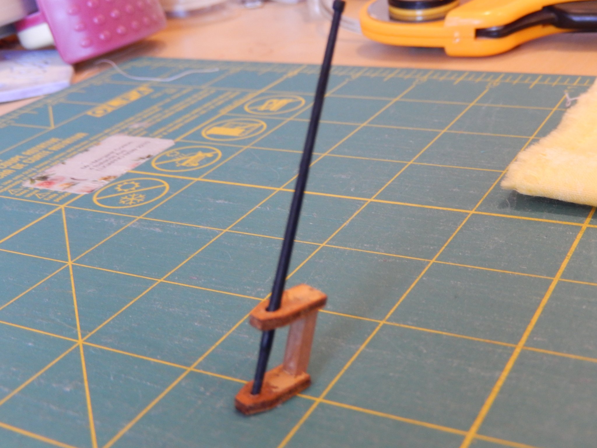
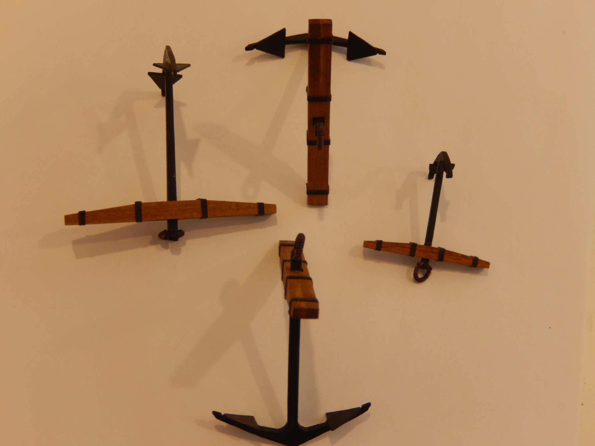
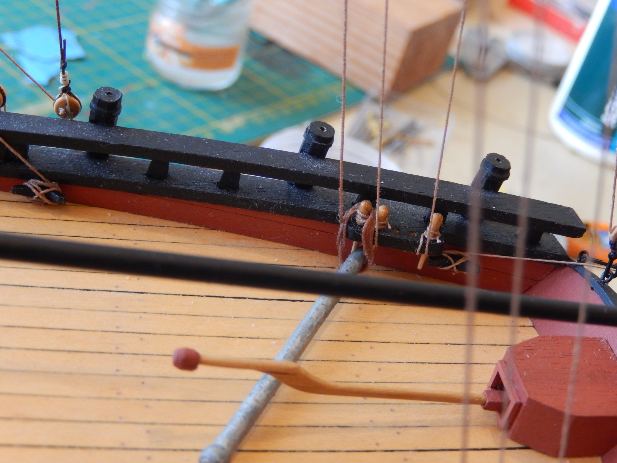
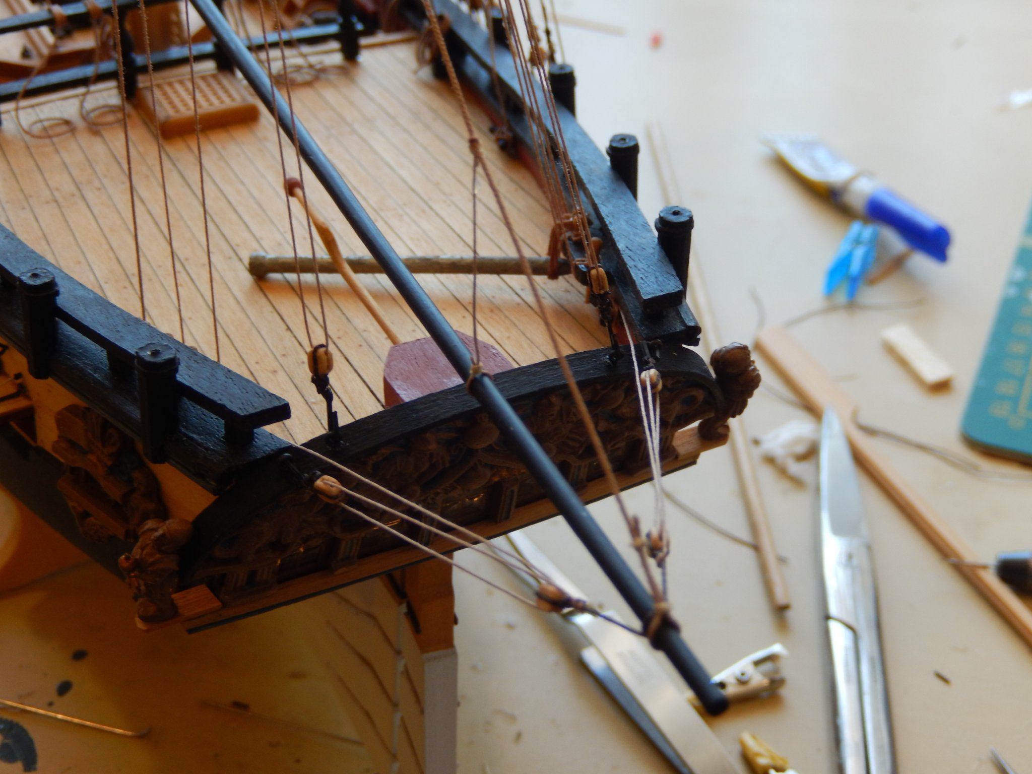
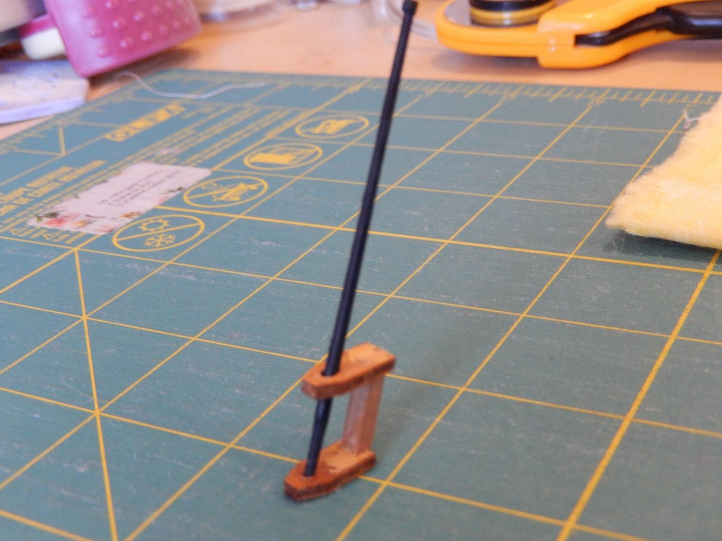
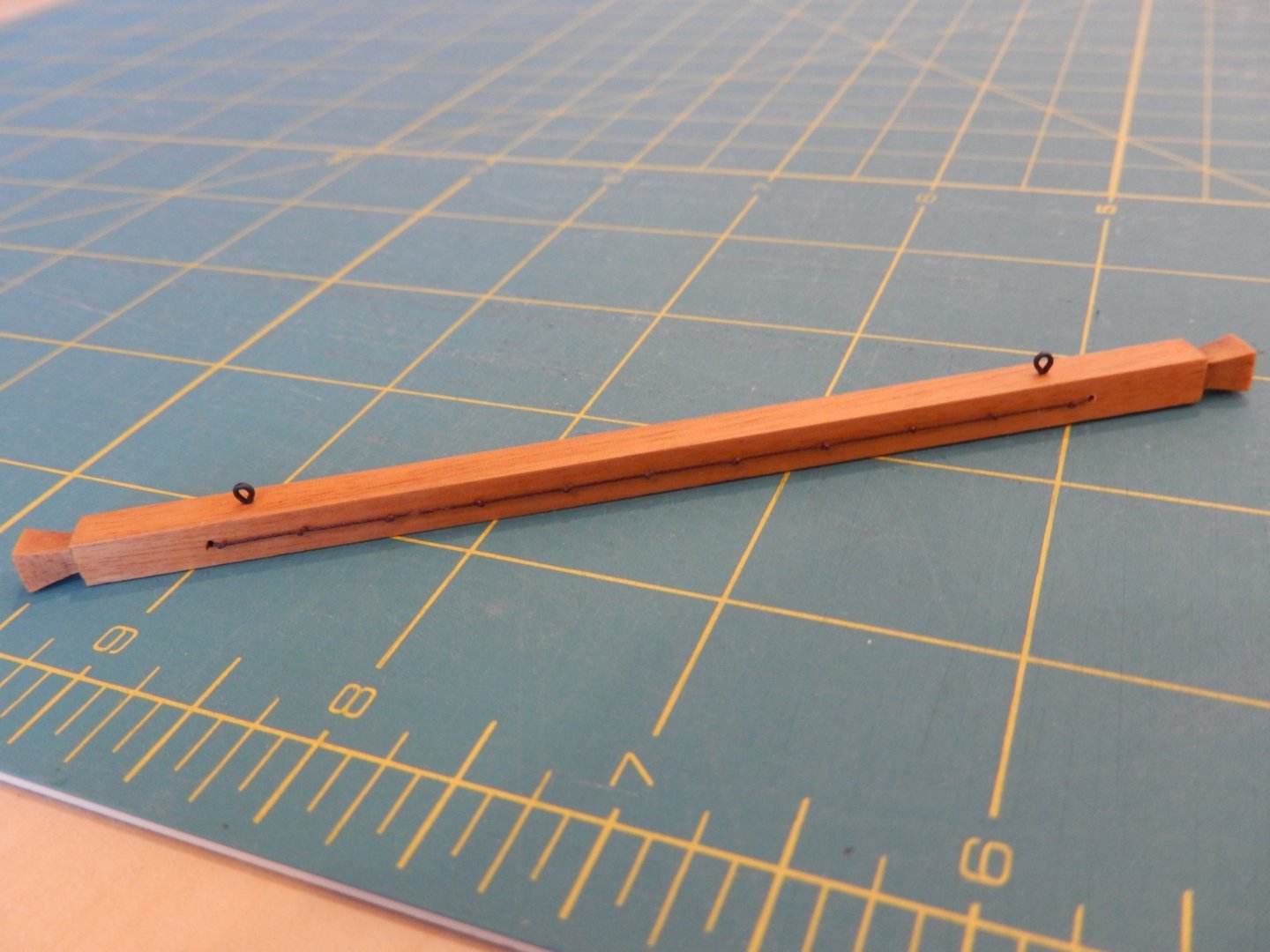
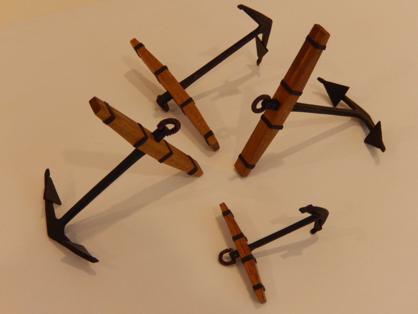
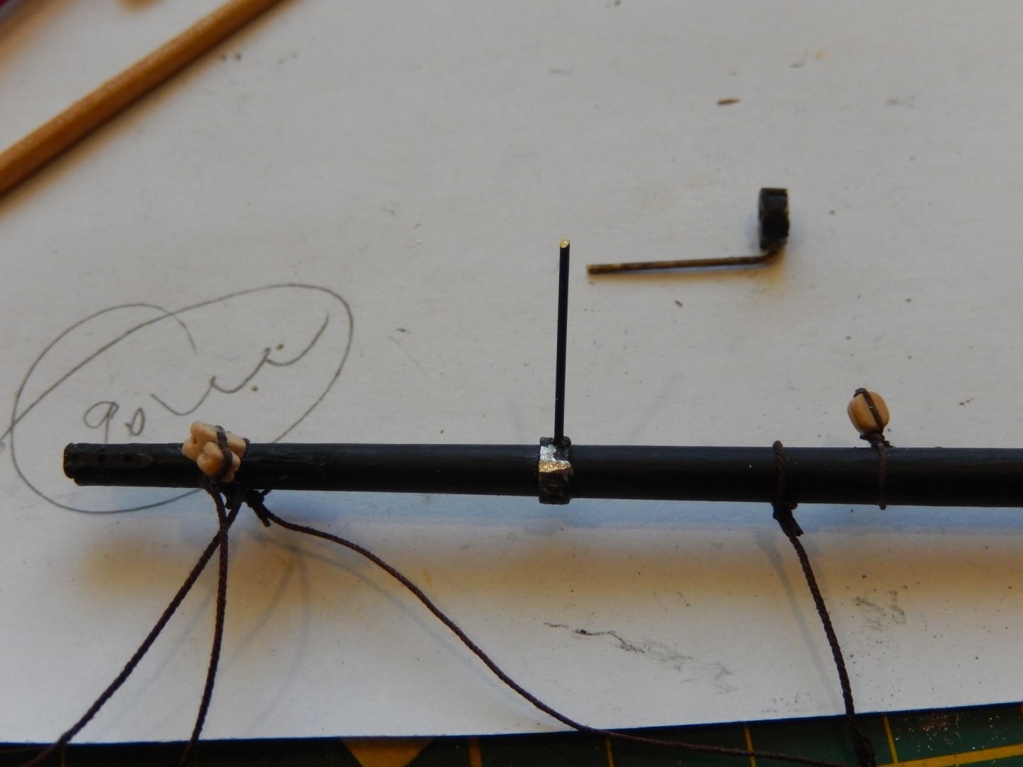
I am finishing off some random bits and pieces: the support for the ensign staff, the fish davit and the anchors. Here is how they turned out. I had a nice photo of the support and painted up and unfortunately I deleted it. This is an earlier photo. here it is: more civilized and dry-fitted. the fish davit. and the anchors. Unfortunately my purchase of HMS Speedy has run into trouble. I had hoped to receive it before we go away just before Christmas. I made a mistake in entering details on the website. In trying to correct it I ran into the security payment system which viewed me as a shady character (!) and refused the transaction. Subsequent attempts seemed to dig a deeper hole. So be careful. Chris Watton has been really good, and I hope to have things righted in the new year.


- 421 replies
-
- 9
-

-
- caldercraft
- granado
- (and 1 more)
-
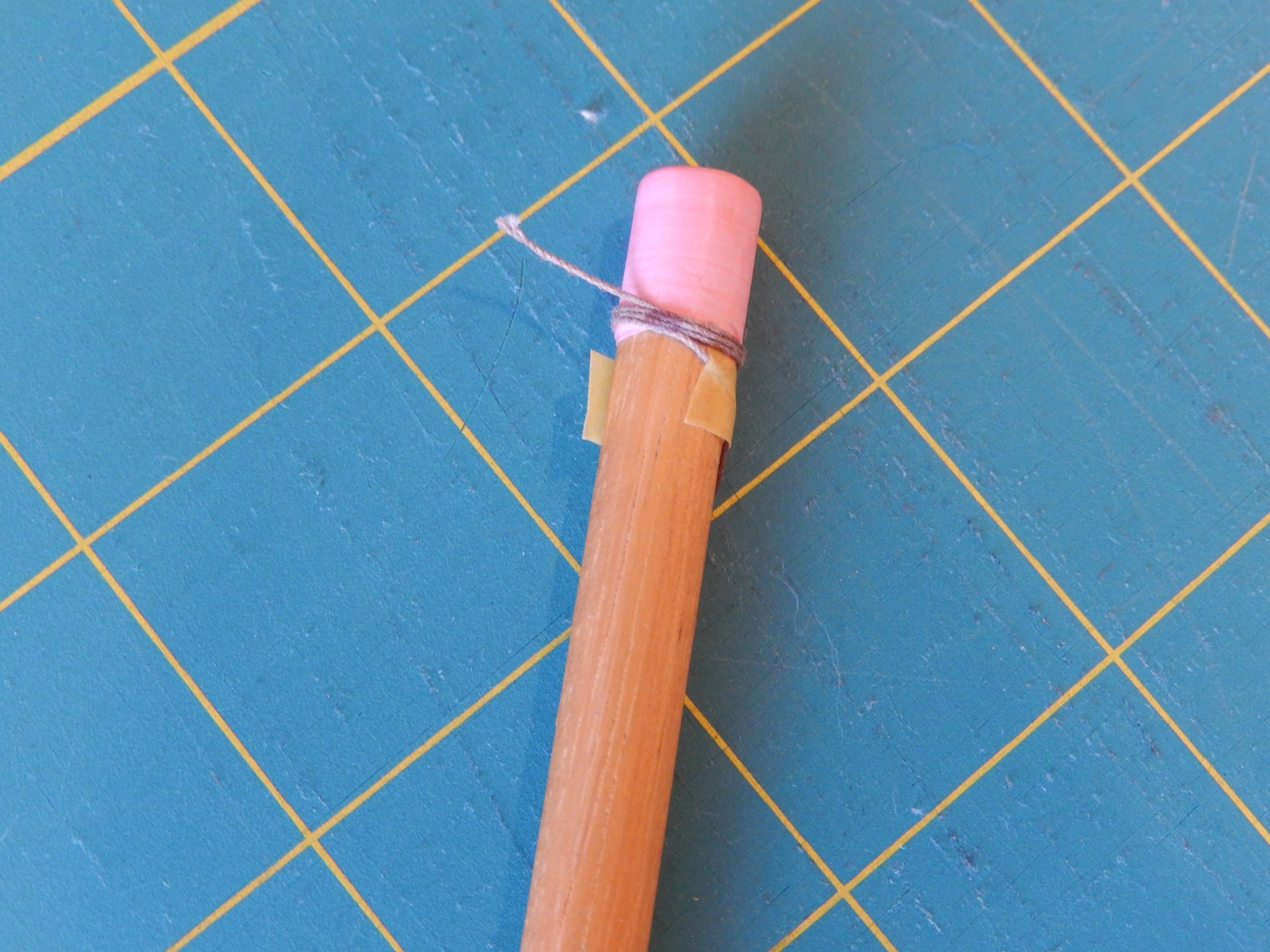
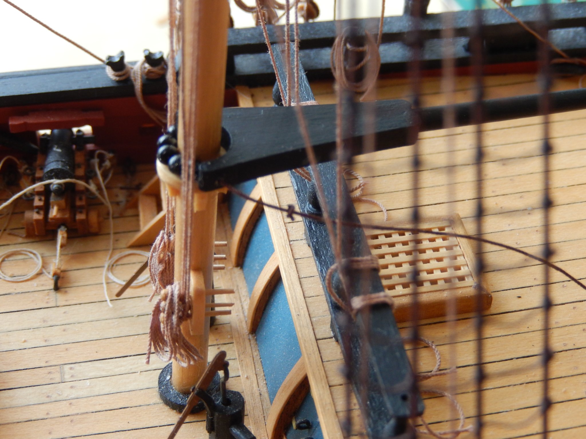
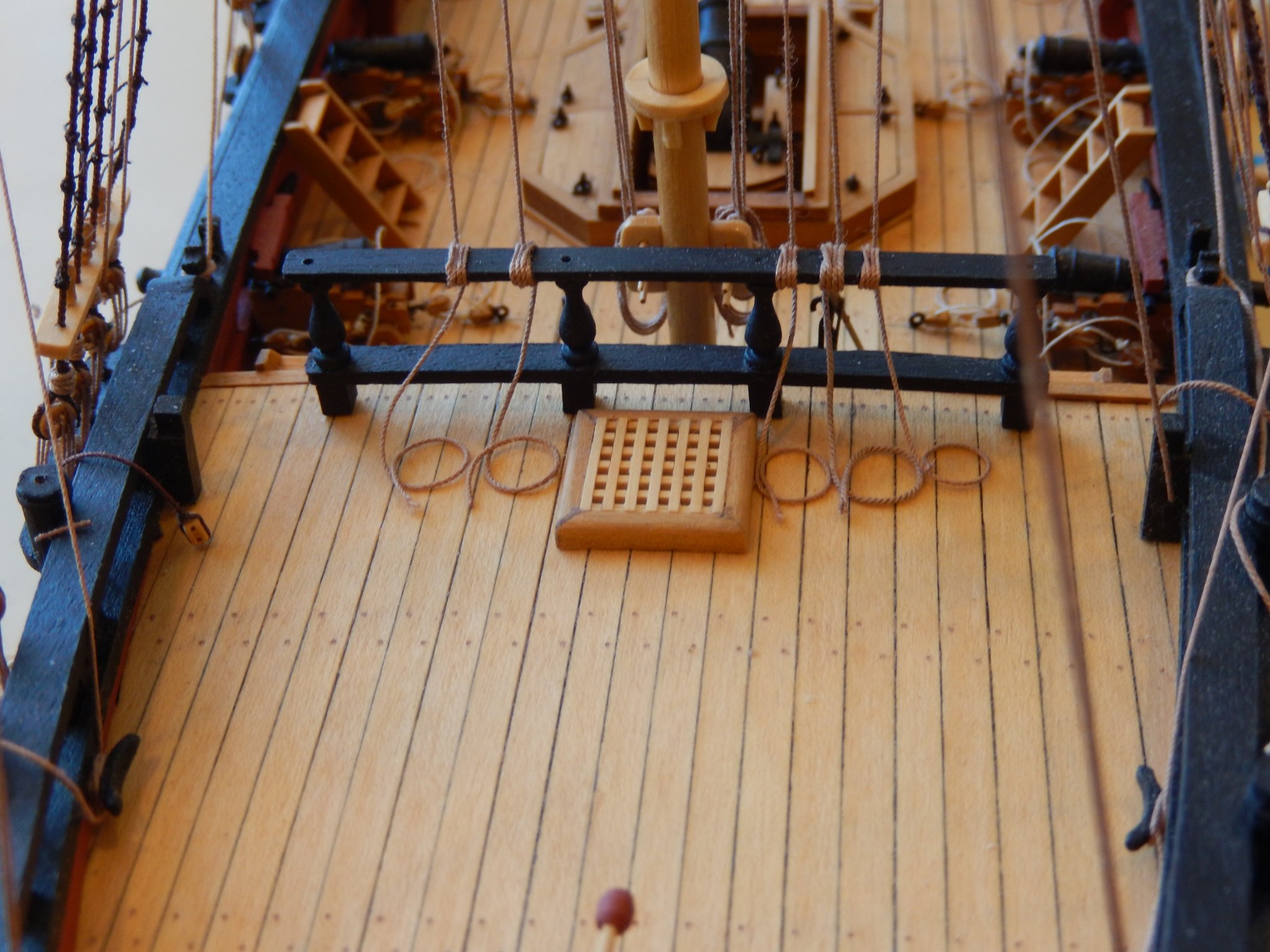
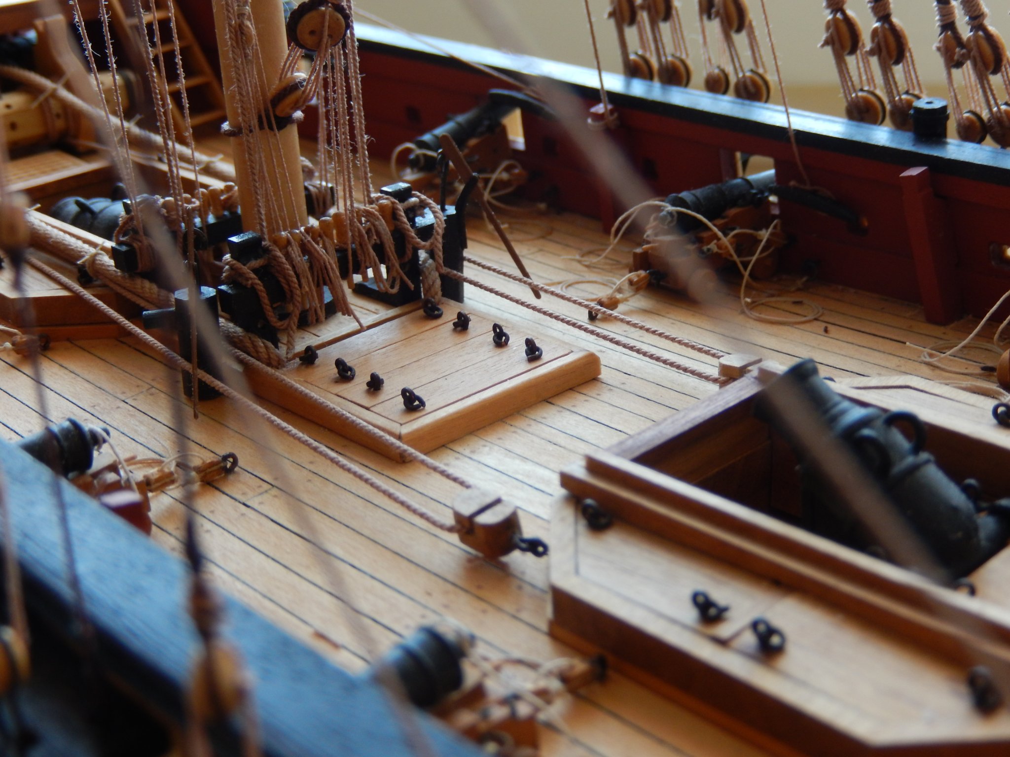
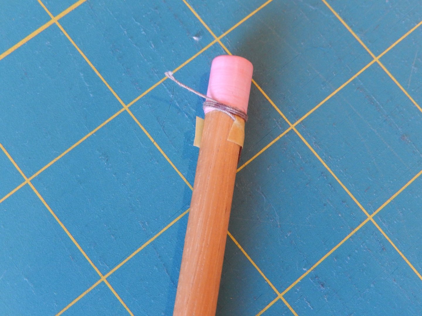
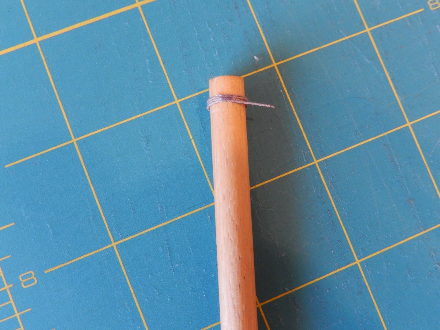
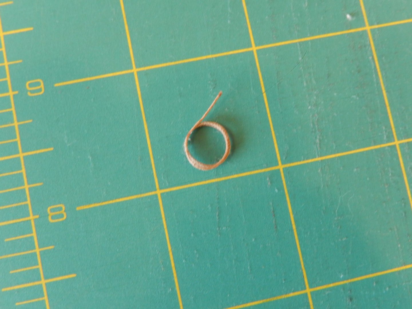
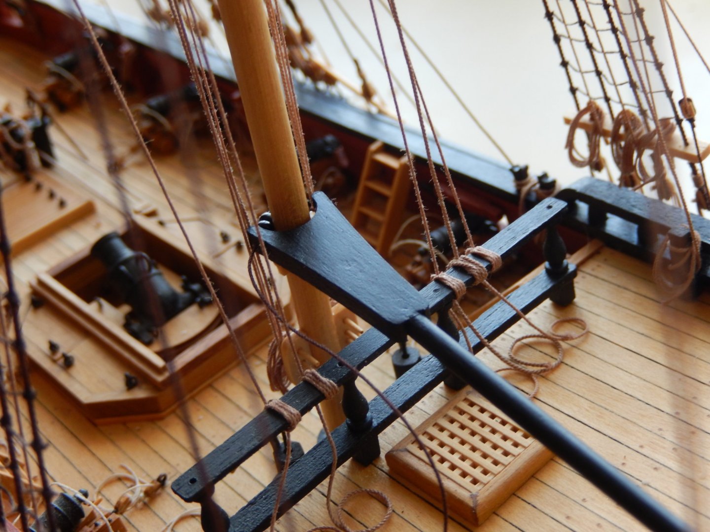
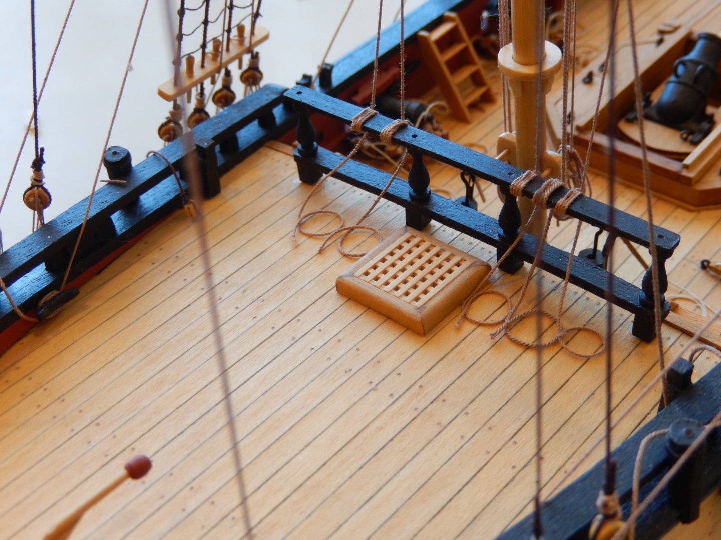
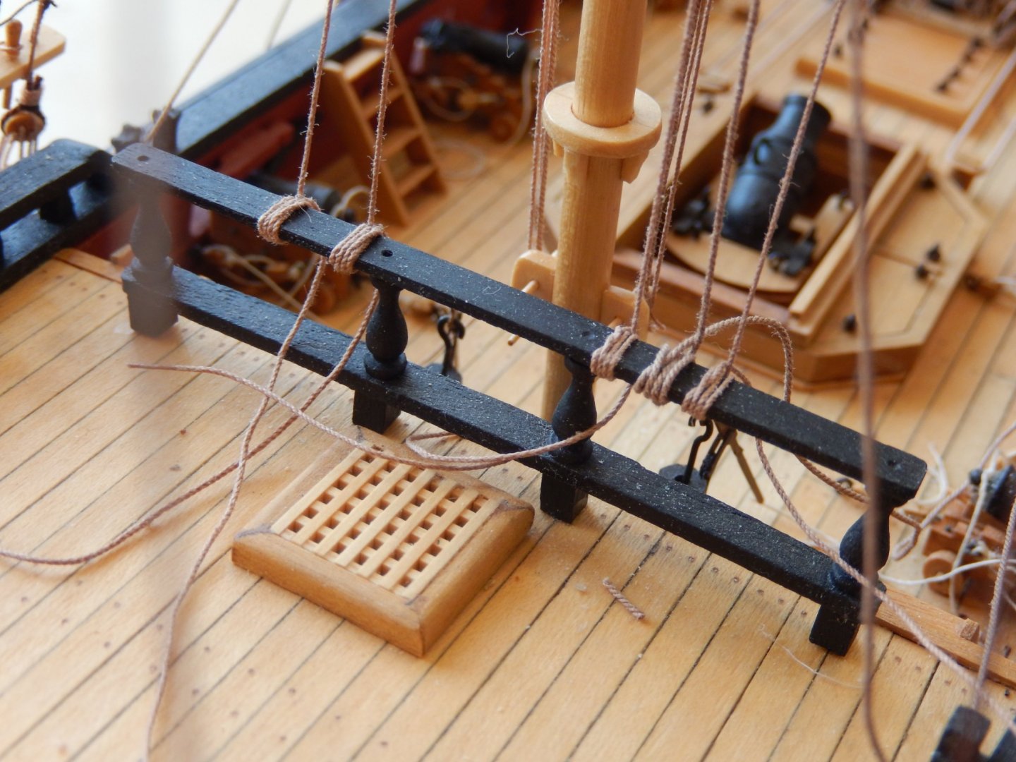
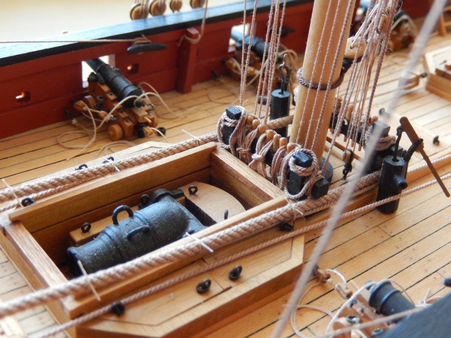
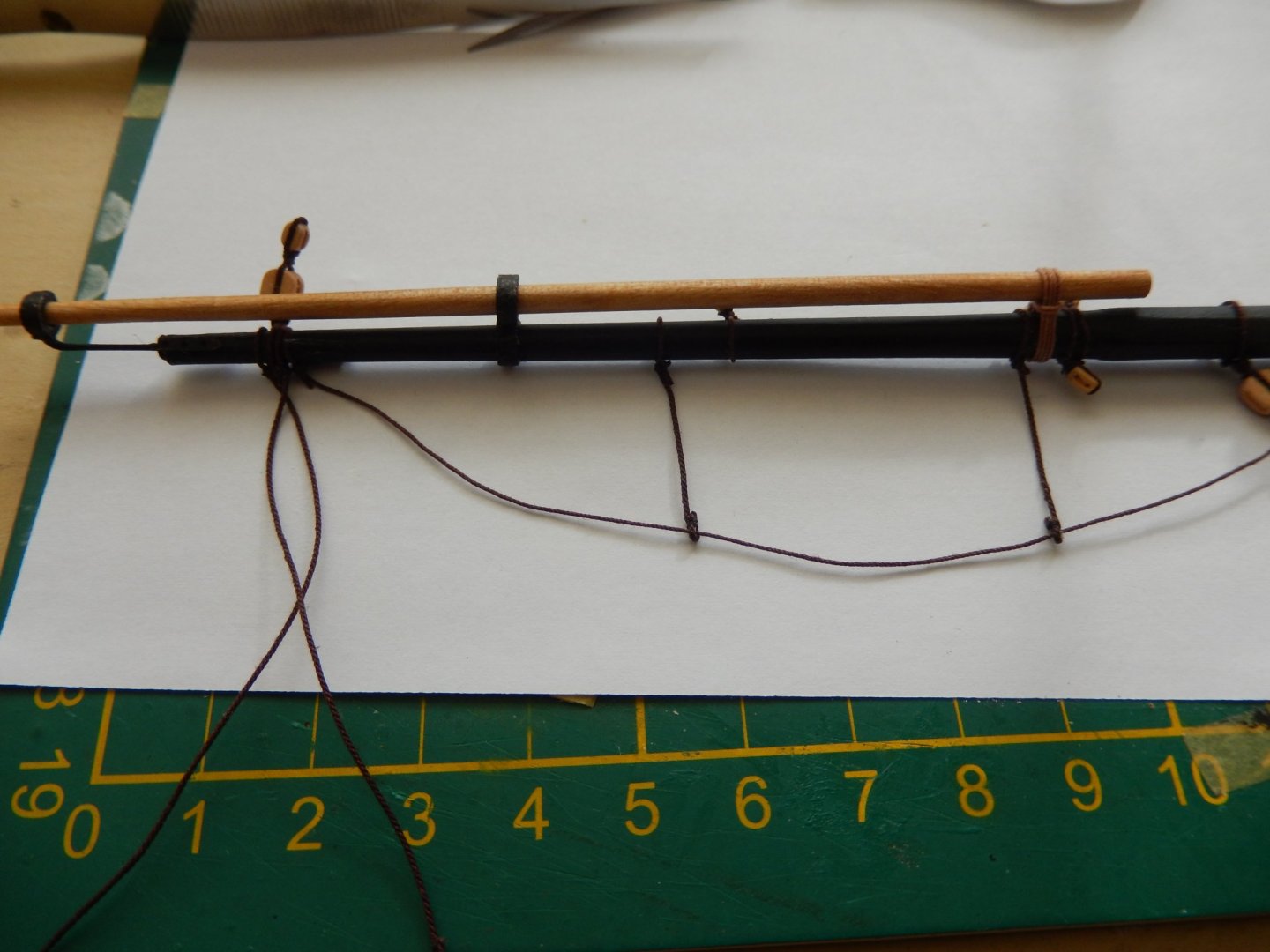
The rigging of the driver gaff and driver boom is now finished, and the end is in sight. I have ordered the HMS Speedy from Vanguard Models, and hope it shows up before we go away before Christmas. In rigging the drivers, belaying the various threads is quite difficult as access is very limited. I now have to make up a fairly large number of rope coils, which, as I wrote earlier, is not one of my favorite jobs. Fitting them over the belaying pins in some of the pinrails is also problematic. Either the pins I are too large, or the holes into which they are fitted are a little too close together, and this adversely affects their appearance. This how I have done the rope coils so far. The results have been acceptable, though I am sure there must be better ways. First, onto a piece of dowel of an appropriate diameter, some thick teflon tape was wound three or four times. Then the thread was wound on, and a drop of CA was applied to stick the layers of thread together. This is shown below. The dab of CA may be seen and the yellow is Tamiya tape to hold the thread. I would have preferred a couple more layers of thread, but this would have provided more difficulties in fitting them over the pins. The assembled coil is slipped off the teflon (if you are careful, it does not stick) - and here is a coil. Now the trick is to get it to hang properly. This is one way. Wet the coil - the CA will hold it together - fit over the pin, then weigh it down (here I used a nail) until the coil dries. After taking this photo, I shaped the coil here to look a little more civilized. In this photo you may see that two of the pins had been removed (they were replaced later) to provide better access in belaying the hanging ends of the rigging. Not the greatest picture, by here is how it has turned out.


- 421 replies
-
- 10
-
-
- caldercraft
- granado
- (and 1 more)
-
Thanks for the kind comments Hardee and Joe. I'm just looking forward to finishing, then doing something perhaps a little different.
- 421 replies
-
- 2
-
-
- caldercraft
- granado
- (and 1 more)
-
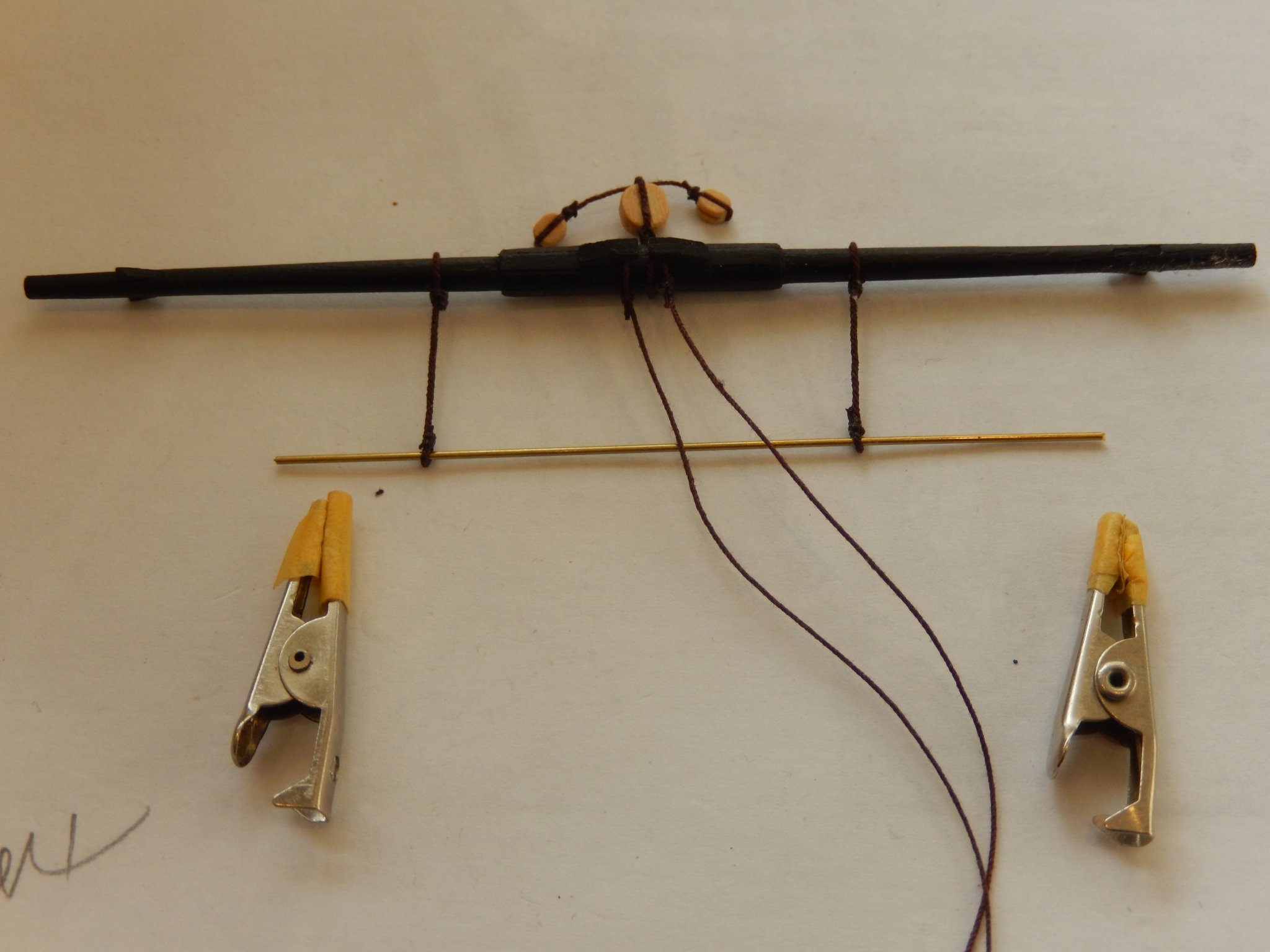
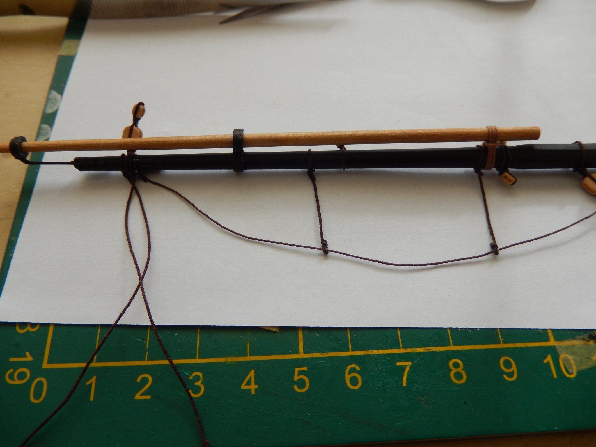
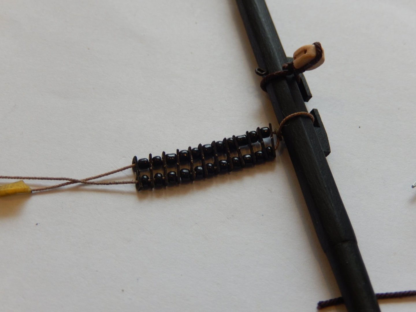
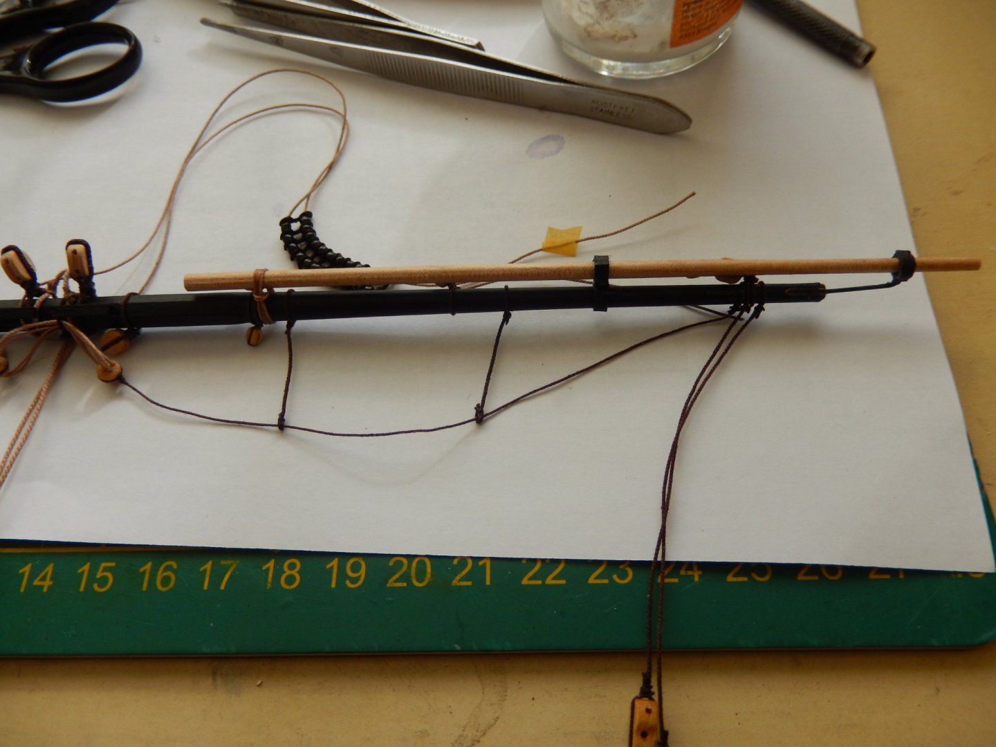
Slow progress still. I seem to have spent most time making rope coils - not one of my favourate things. The driver boon has now been installed, but not rigged yet. It's slightly awkward job - access is difficult - and perhaps this may help someone. The thread upon which the parrel beads were loaded is about 100mm long. This enables the boom to be pulled away from the mast and made more accessible. The thread is passed through the second of the driver boom jaws, and the thread is then pulled taught (shown below). An overhand knot was then tied around the thread, a dab of dilute PVA put on it, making sure not to get the PVA on the parrel thread. Once dry the ends of the knot were cut off, the knot slipped up to the jaws and glued, and the hanging end of the parrel thread then cut off. In the photo below, the knot may be seen about 15mm from the jaw before being slipped up to it At the moment I am deciding what to do next. The most likely is HMS Speedy by Vanguard Models. Chris Watton is the designer and he did a wonderful job on Amati's vanguard.

- 421 replies
-
- 14
-
-
- caldercraft
- granado
- (and 1 more)
-
Thanks Bob and Peter. I did this (below) before I saw your replies. Unfortunately I cut off the threads too short to provide a more substantial set of coils. The result is probably adequate, but I wish I had seen your two solutions. I still may play with it a bit - along the lines you two have shown me - but I don't want to completely stuff it up. At the least I see from the photos I should improve their shape and positions.

- 421 replies
-
- 9
-
-
- caldercraft
- granado
- (and 1 more)
-
I have only just realised that I have almost finished. Here are the errors I have found in the plans - ie: inconsistencies between the instructions and the plans. Here is progress. Rigging the driver gaff is quite a difficult proposition. Putting the parrel in place is easiest by rigging it below its ultimate place on the mast, then moving it up. The following shows the complexity of its rigging - and there is still one more bit to come. Here are the various falls belayed to the breast rail. On the Joytika website they are shown like this, simply cut off - no rope coils. I'm not sure whether to follow this or in some way try to but on coils.
- 421 replies
-
- 6
-
-
- caldercraft
- granado
- (and 1 more)
-
Thanks Shipman, Brian and Sam for your comments. I am a bit pressed for time at the moment and will try to reply in a little more detail later. Briefly, Shipman - I now regret not looking at the Amati version of Granado. The materials etc. for the Vanguard(Amati Victory Models) were infinitely better, though of course it is a far more expensive kit. Brian, I think the substitutions are worth it, but I guess I'm biased. Incidentally there are a few inconsistencies between the instructions and the rigging plans that I will note later - not a big deal, but annoying. Sam - I do have some beeswax, but have never used it. I have found saturating the thread with very, very dilute PVA works fairly well.
- 421 replies
-
- 4
-
-
- caldercraft
- granado
- (and 1 more)
-
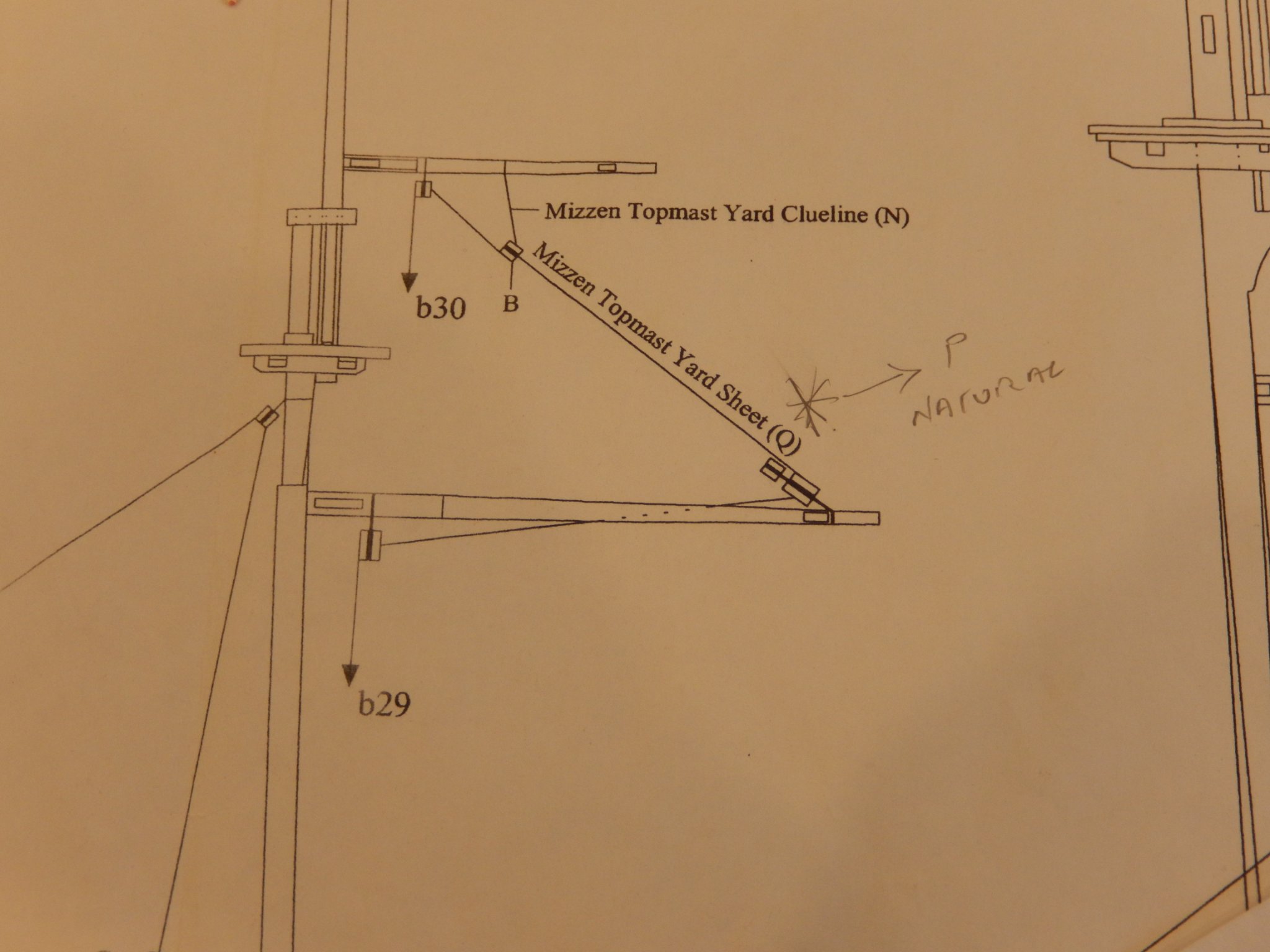
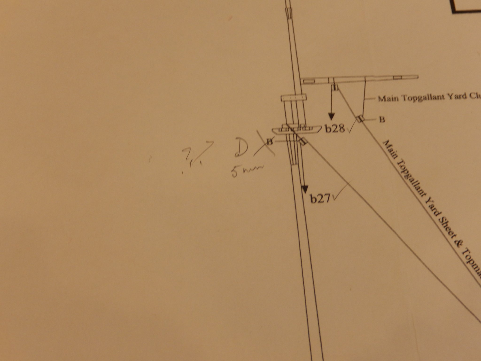
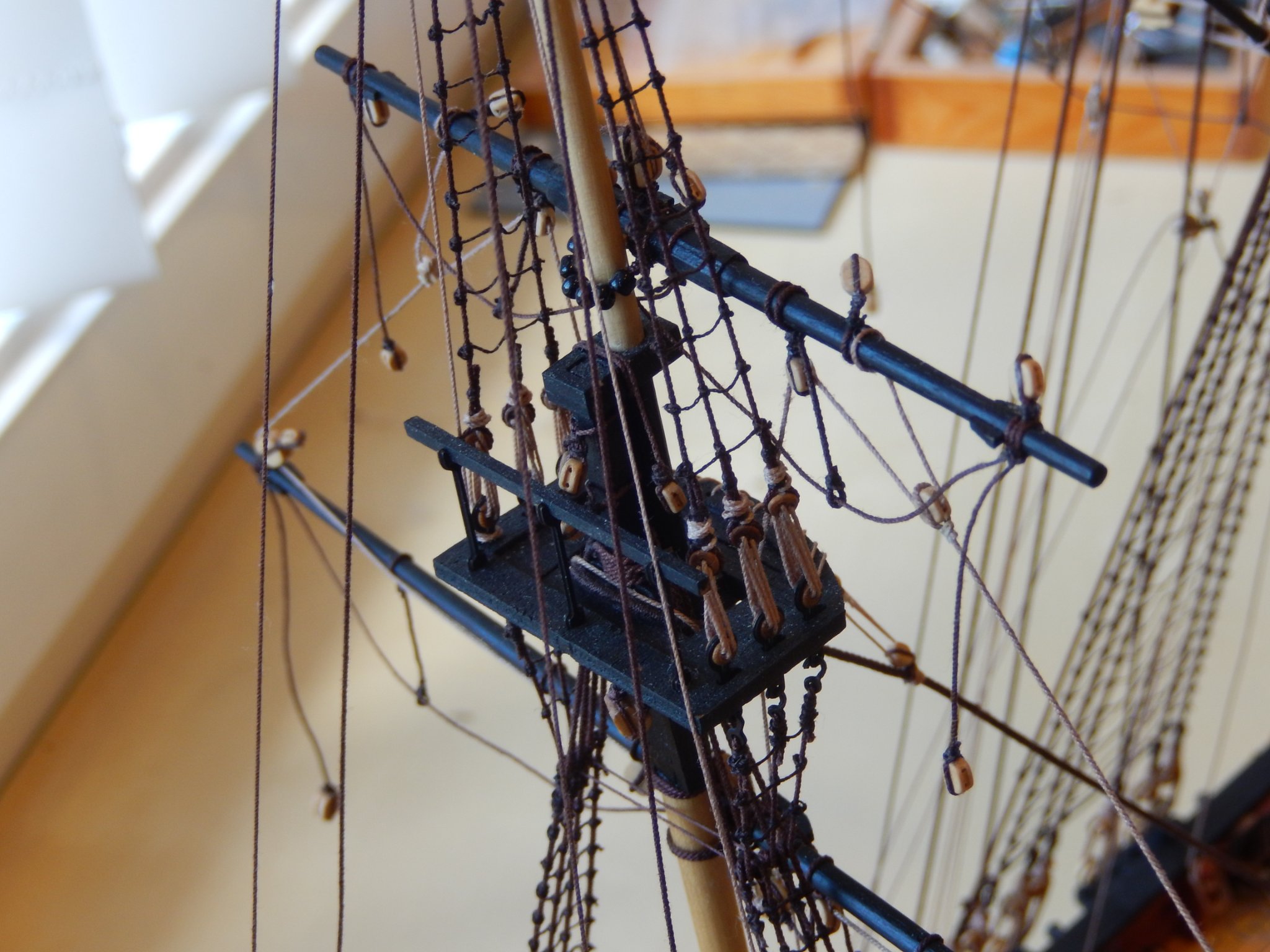
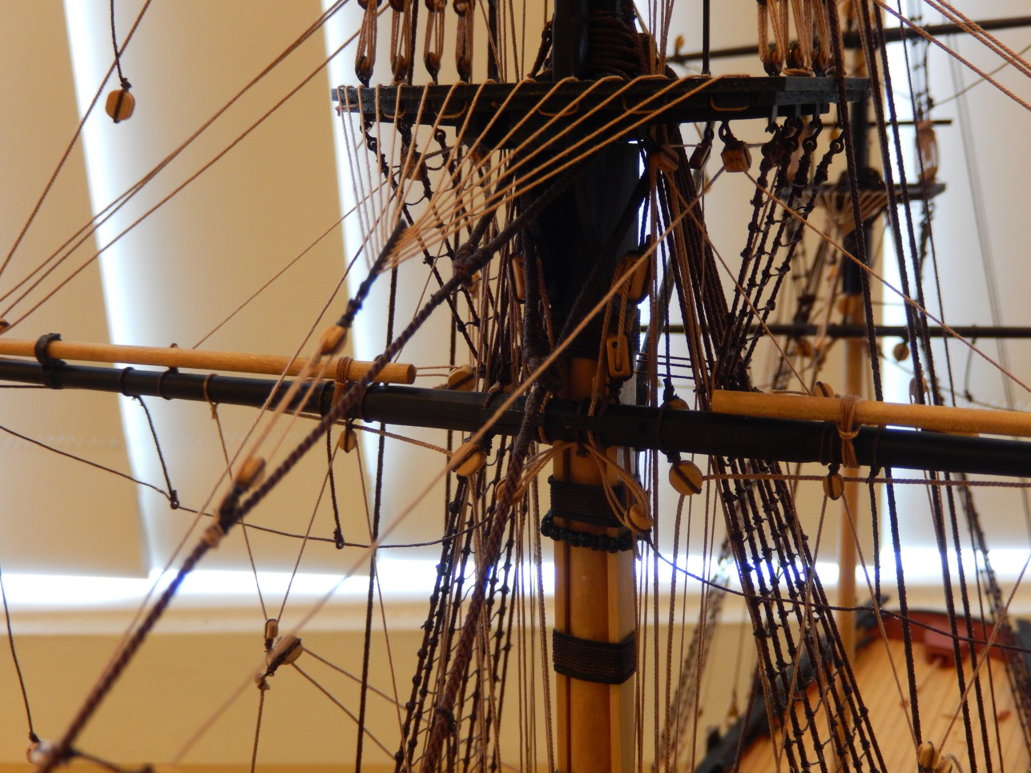
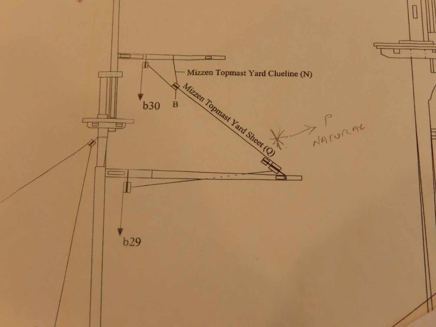
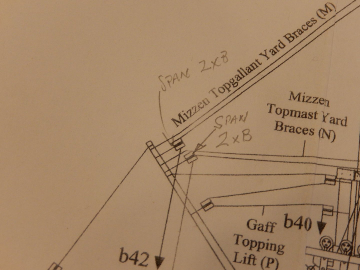
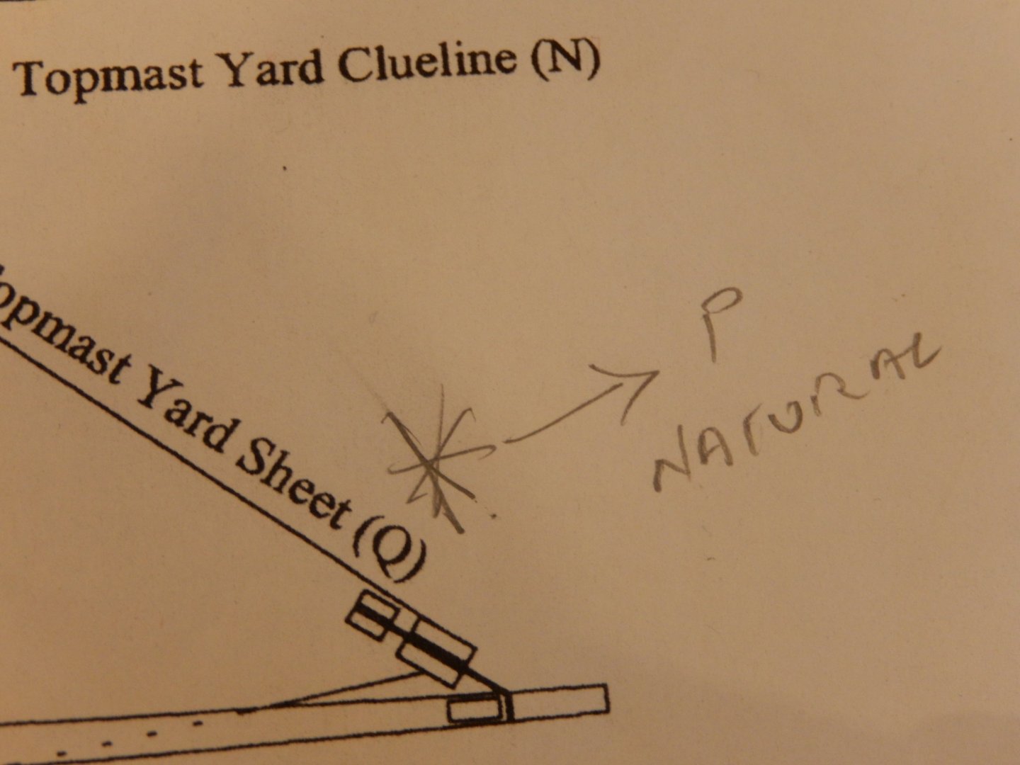
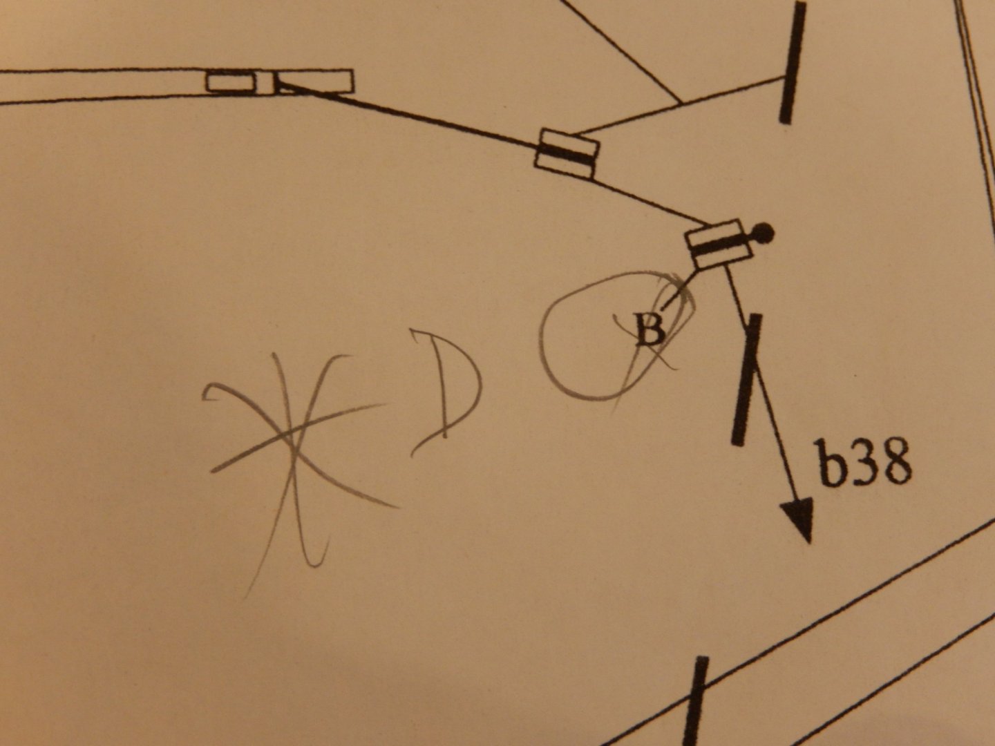
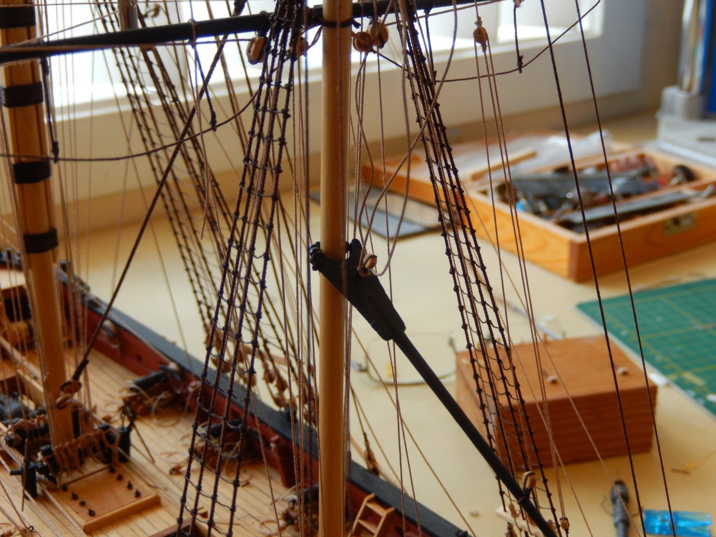
Rigging the mizzen topmast yard is now close to complete with the yard sheets and the cluelines done. While it has come out acceptably, getting the rigging correct while making sure the crossjack yard and the topmast yard both parallel and horizontal was not something I would like to do again. Moreover, belaying the lines to the centre pinrail ran up against the same belaying problem that I found with the jeer bits; not enough room. The holes for the pins are either too close together or the pins are themselves too large. Eventually I was successful, but it was rather frustrating. I'm not sure how I will later put on rope coils. The belaying shown below has been tied off, but the lines have not yet been glued or cut off. (You never known when a further adjustment may be needed.)

- 421 replies
-
- 17
-
-
- caldercraft
- granado
- (and 1 more)
-
Thanks for the encouragement Sideways (?) and Hardee etc. One thing I sugges, when belaying lines, particularly if you use Syren thread, is to wet the line near the belaying point. It makes the thread far easier to manipulate in tying it off. The Syren thread tends to be a bit stiff. I use a paint brush dipped in water, then running it along the lower bit of thread. Works well.
- 421 replies
-
- 1
-
-
- caldercraft
- granado
- (and 1 more)
-
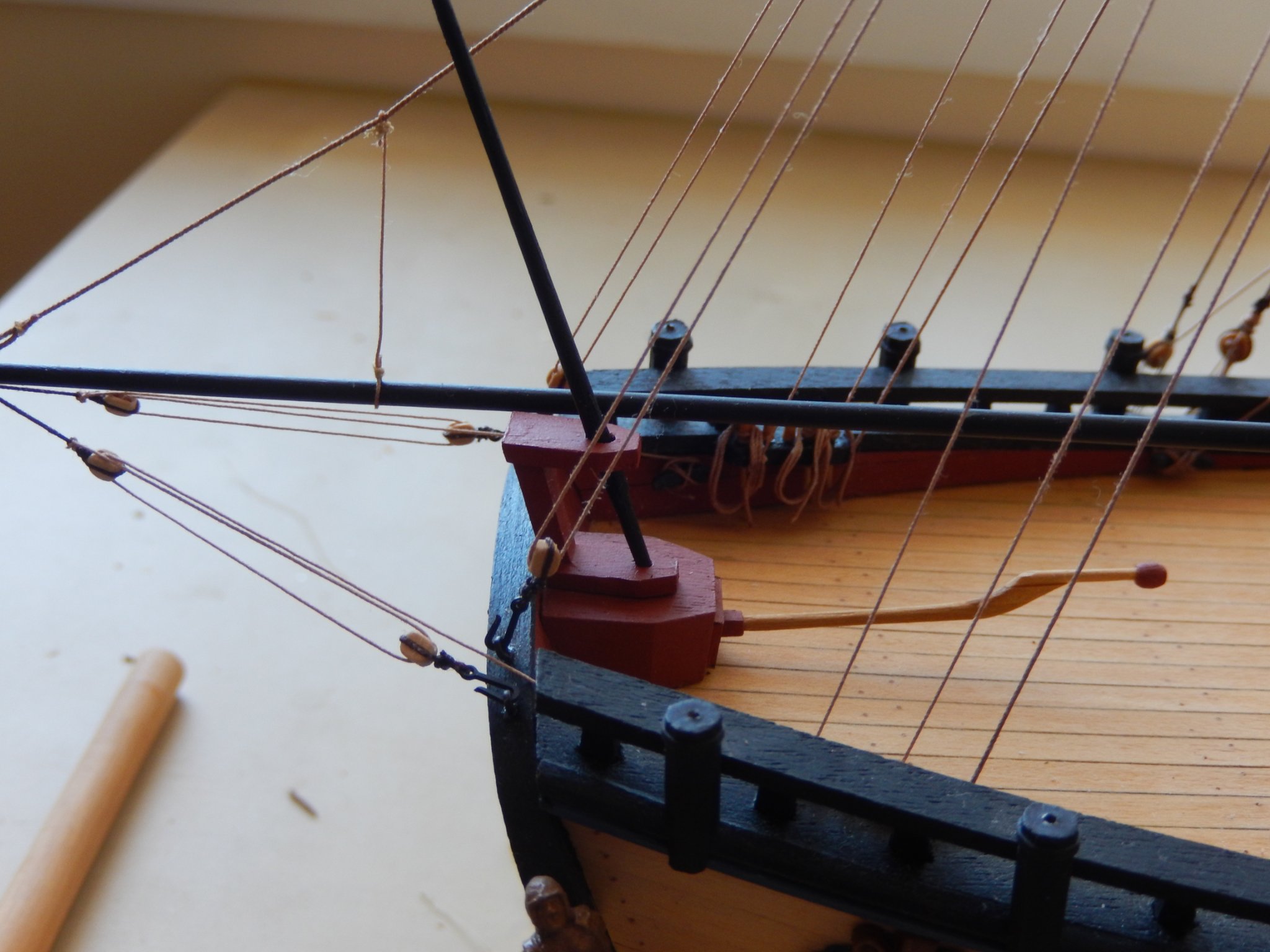
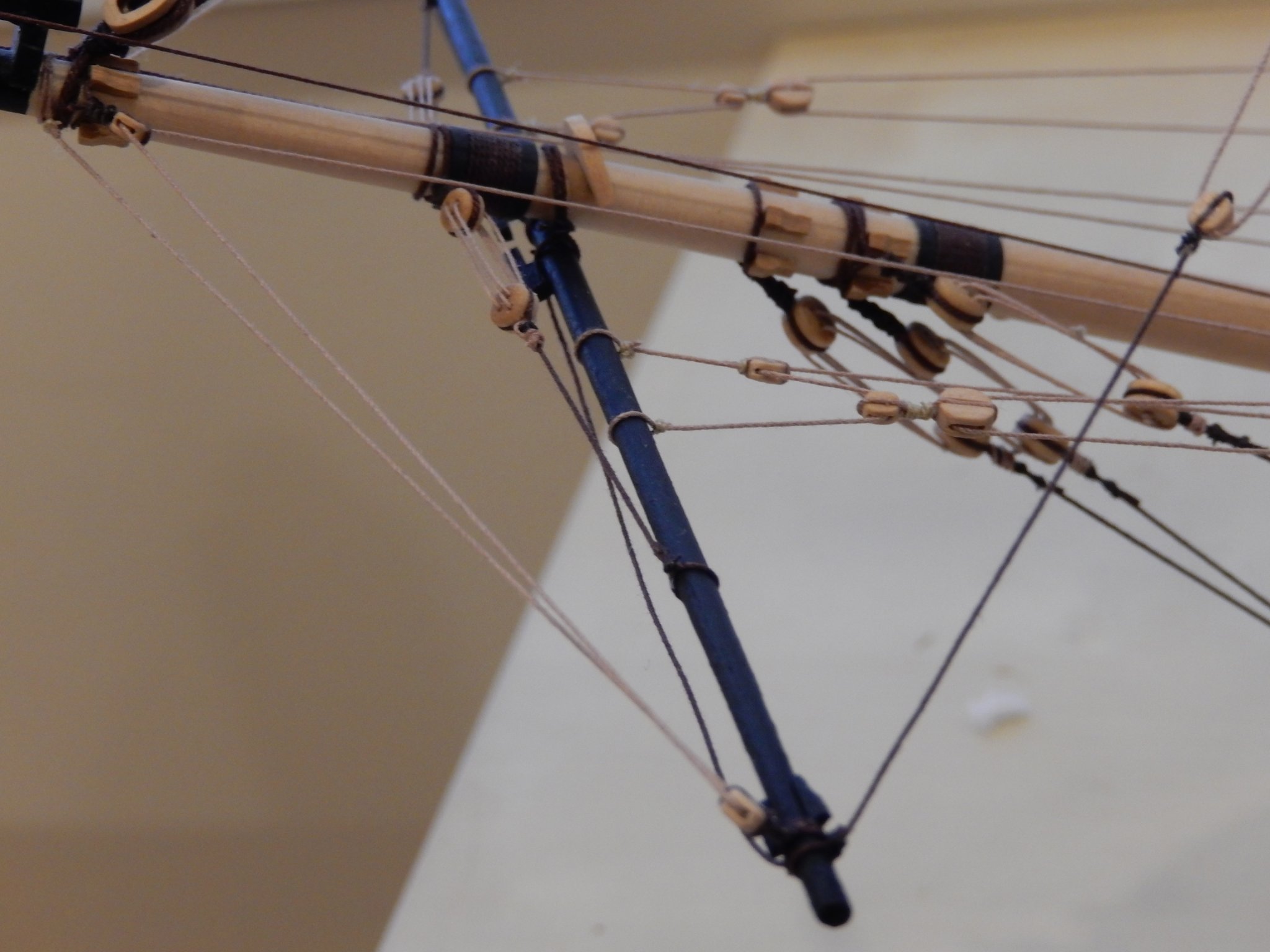
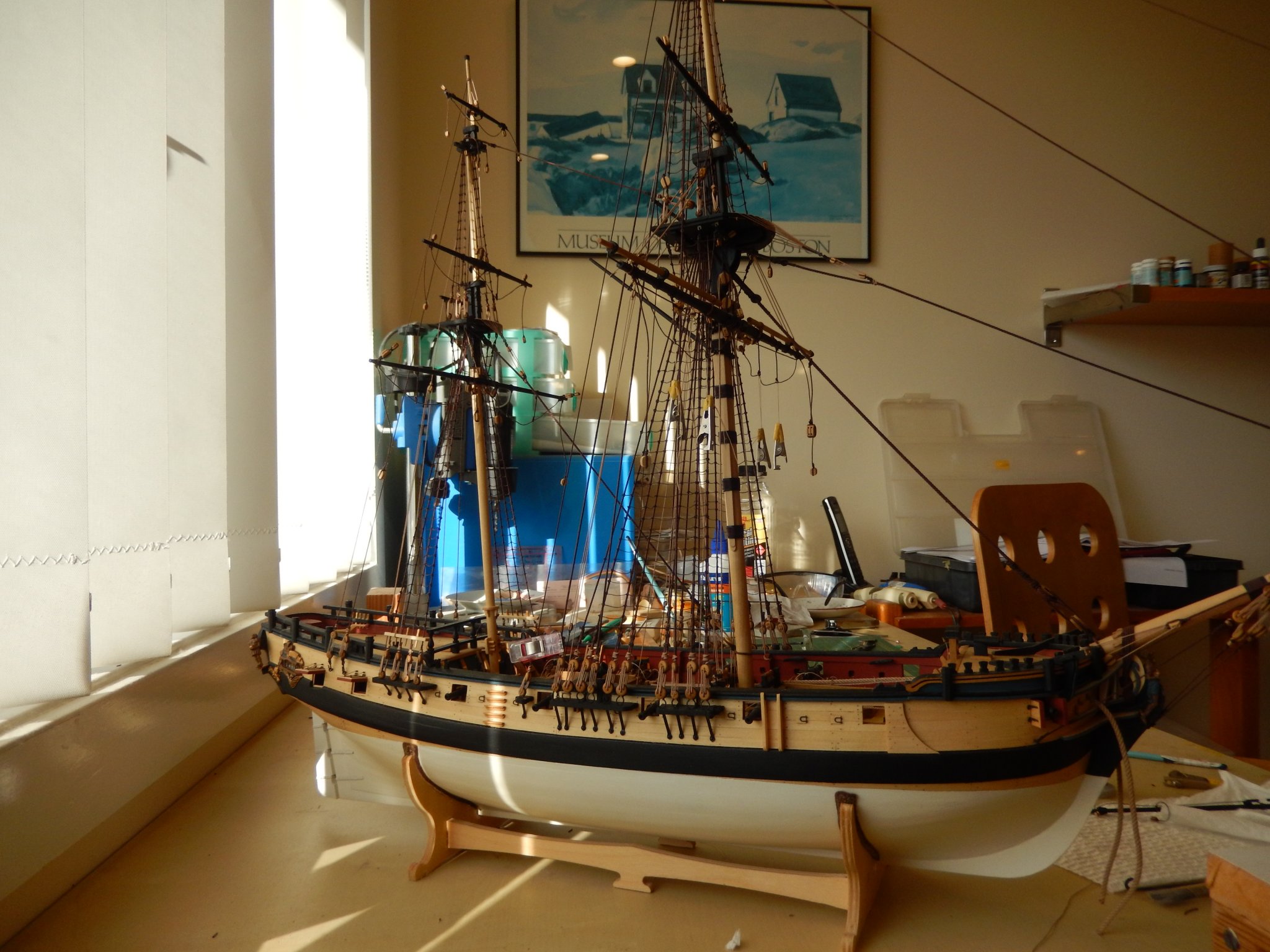
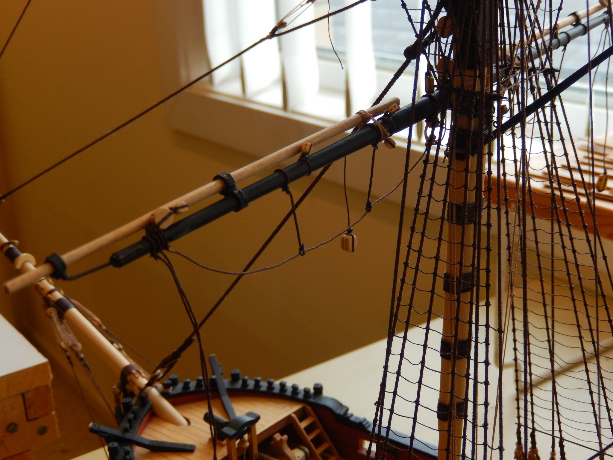
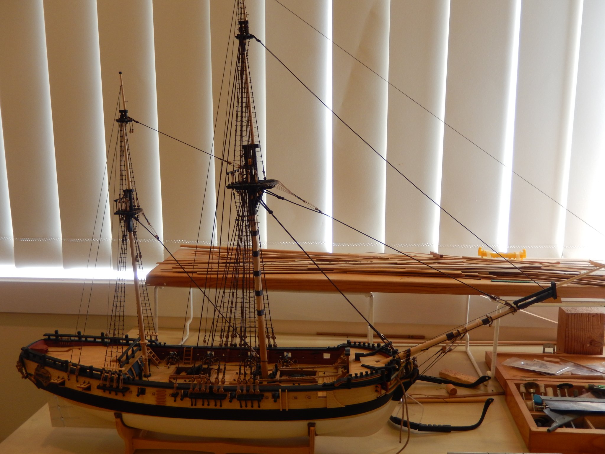
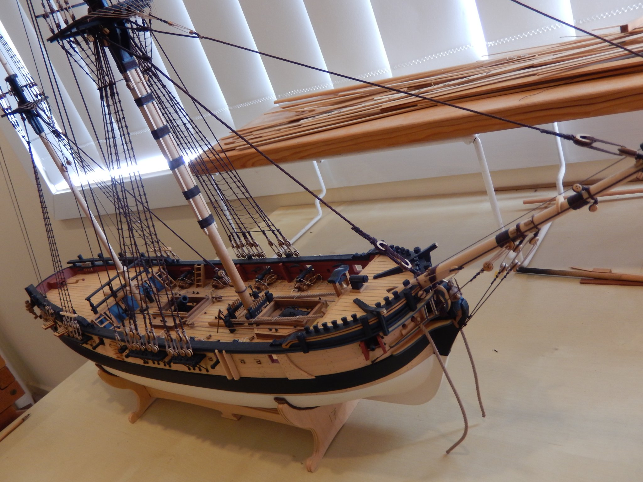
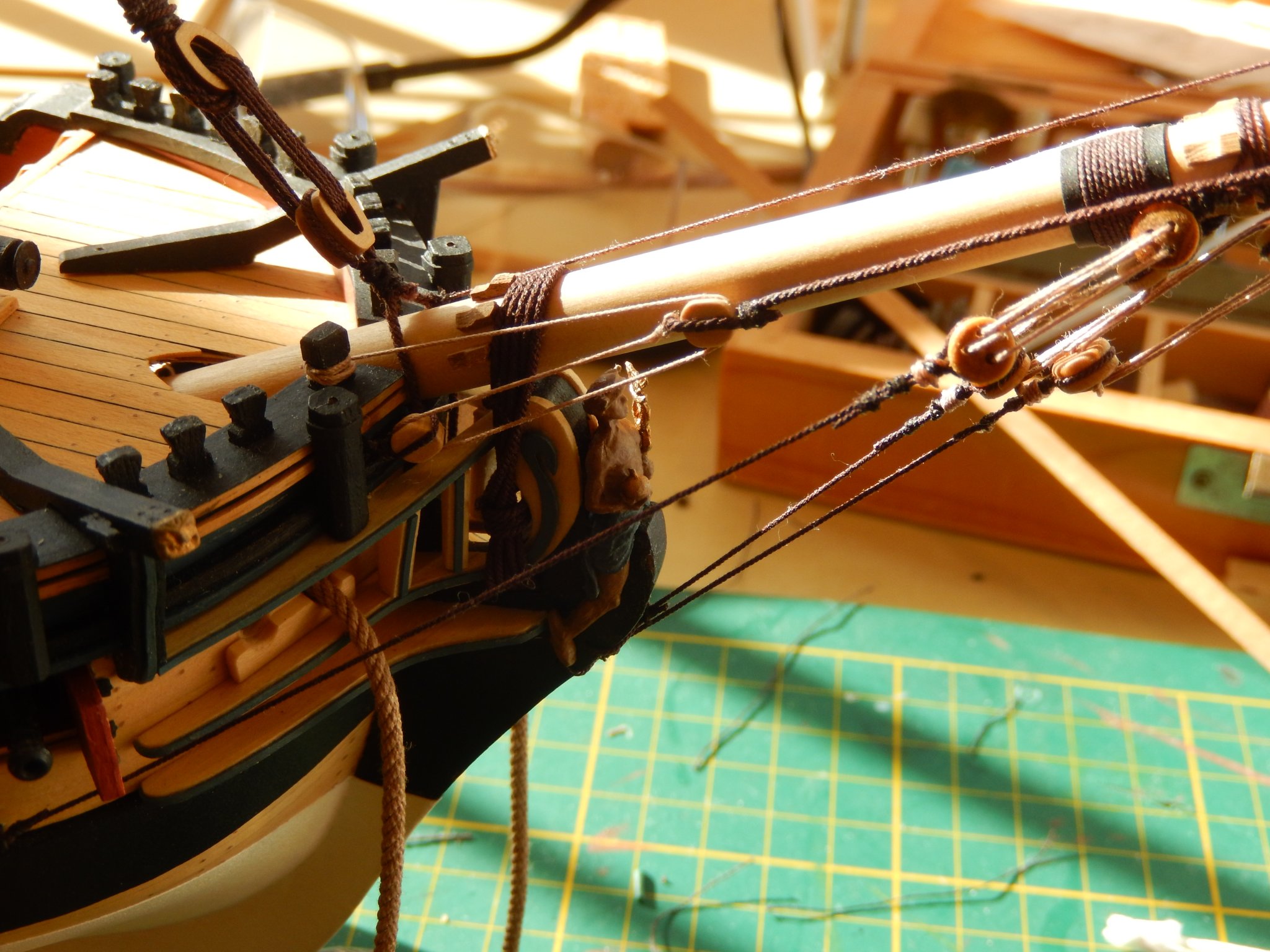
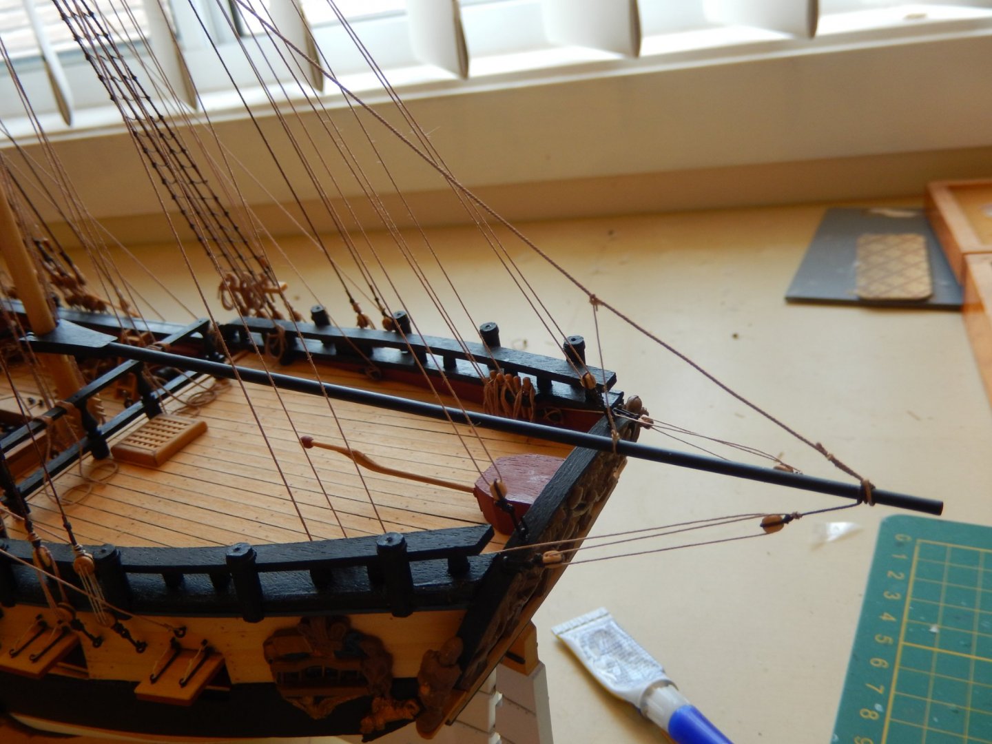
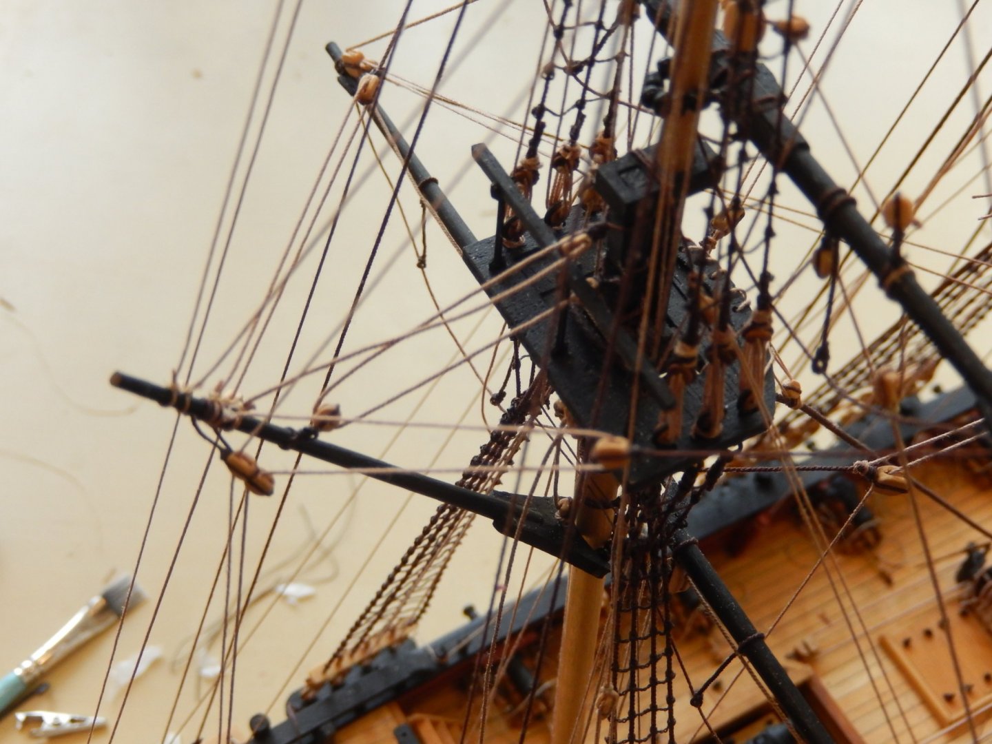
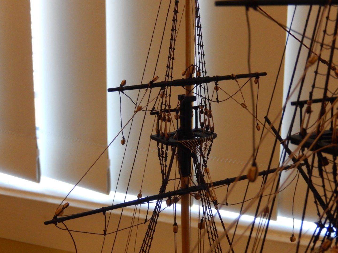
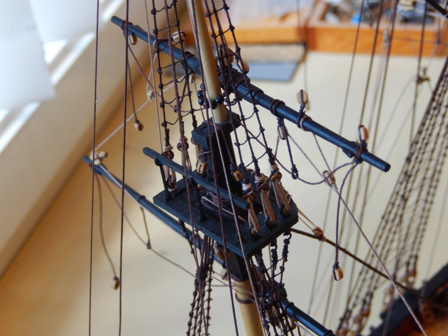
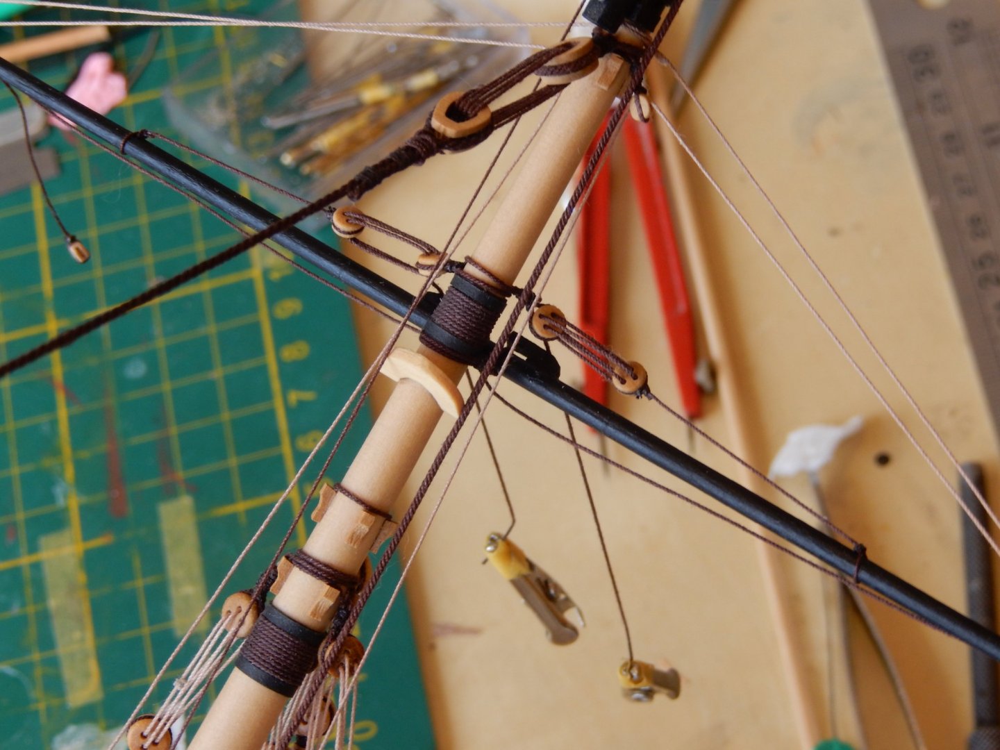
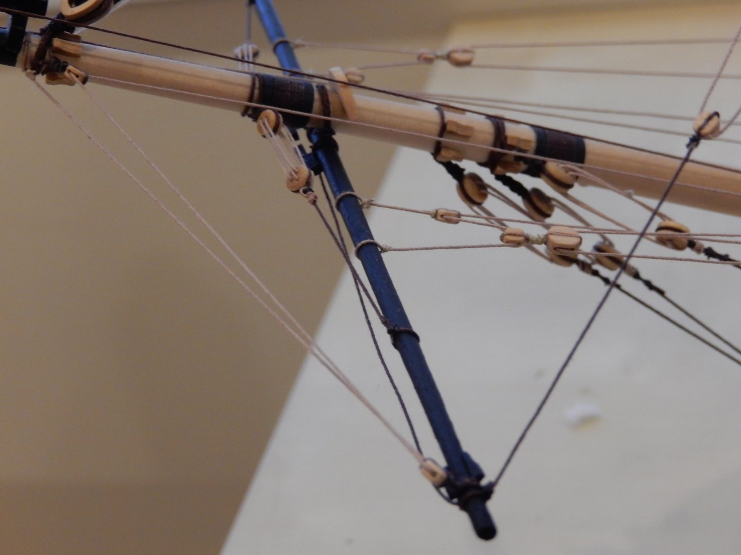
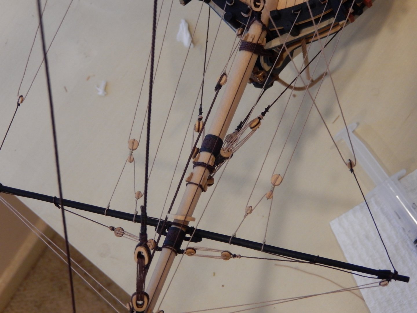
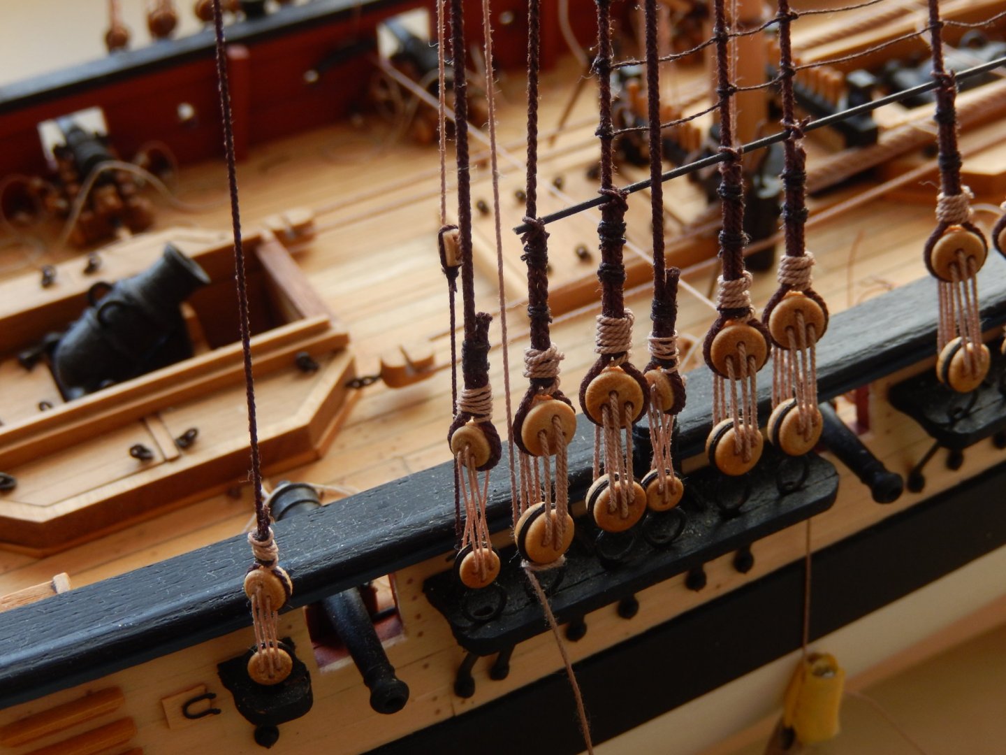
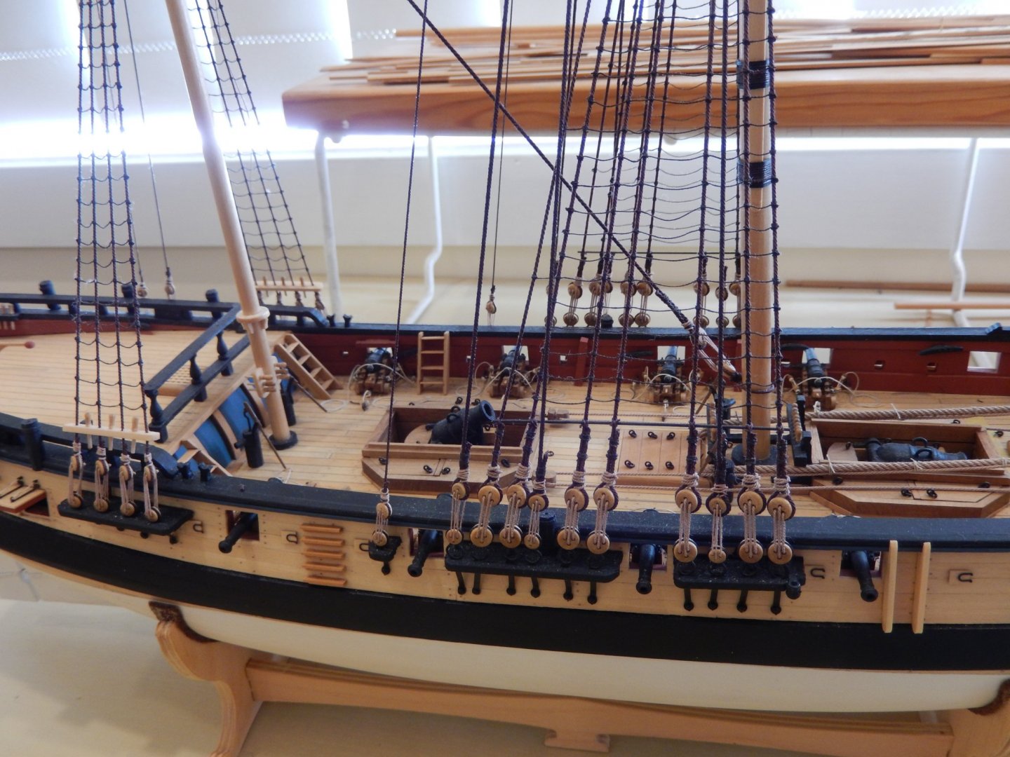
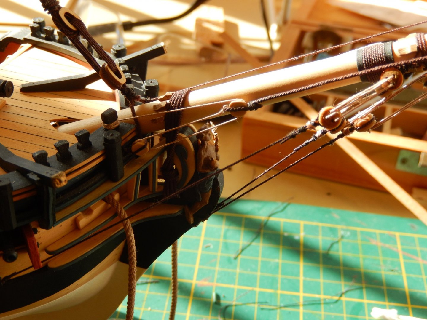
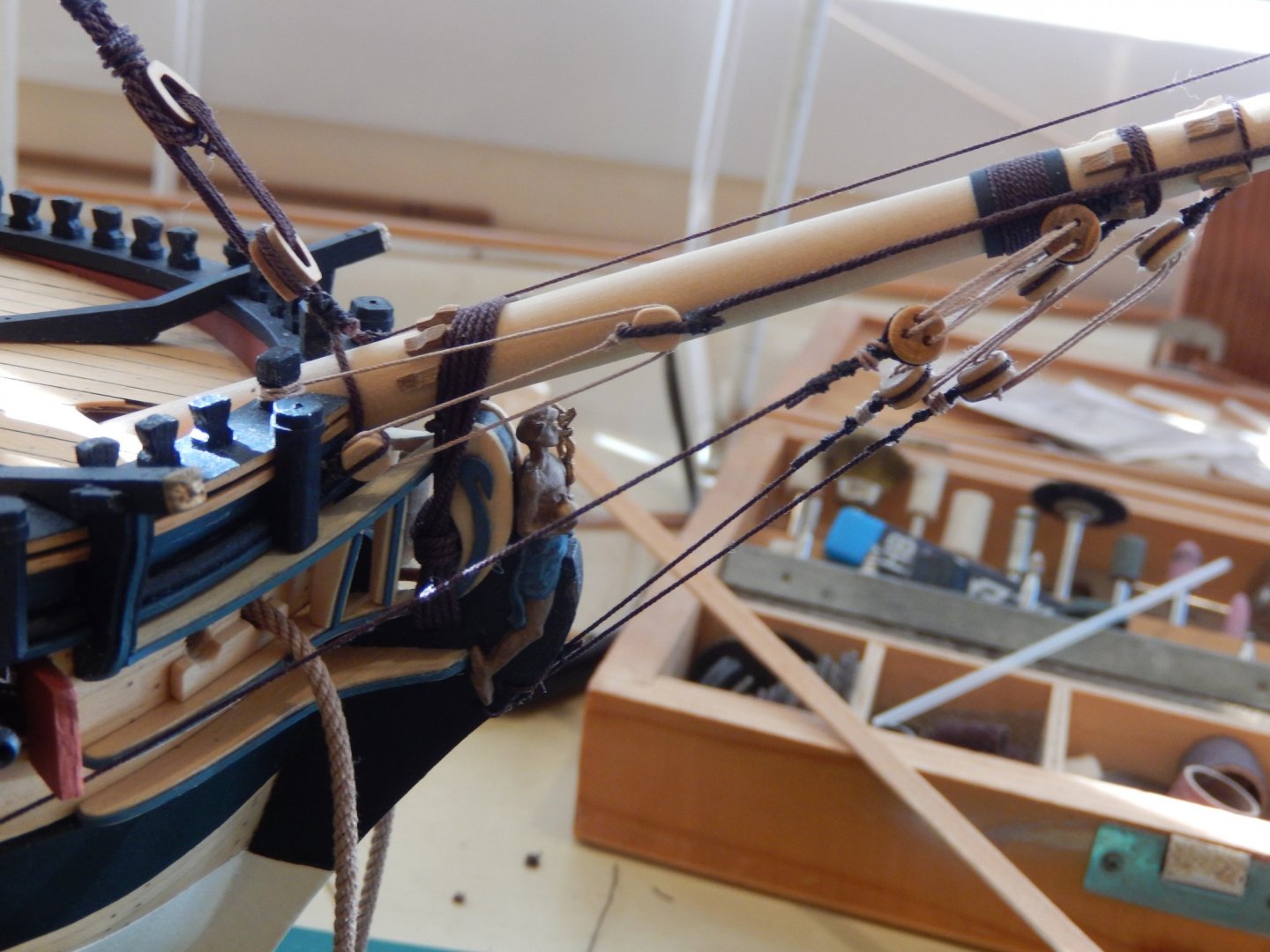
Thanks Joe - a rather late thank you. Well the main mast and bowsprit rigging is finished. Ship building has not been a high priority lately. Here is the bowsprit. After a few silly mistakes it has come out quite well. I have used small alligator clips as weights extensively. They keep lines taught while the rigging process goes on. This also shows one of my mistakes (now corrected) - using black, or in my case, dark brown instead of natural for the lanyards. Obviously the rigging is very crowded indeed. For much of the rigging, 0.25mm thread is specified. The Syren thread comes as either 0.2 or 0.3mm. I chose 0.3mm. This, I found, caused a problem with the 3mm Syren blocks that I used. When using CA to aid threading through the blocks, the thread did not want to go through. My solution was to drill out the holes with a 0.6mm bit. Doing it before a block was mounted was easy - doing it in situ was sometimes rather hair-raising. Another problem is the lack of space between the belaying pins. Once the various lines are belayed, rope coils have to be fitted. This was far easier said .... An extensive vocabulary helped. The result is acceptable, though I now see that a bit of adjustment is needed. I have included the following photo to illustrate just how crowded and complicated the rigging is. This is how things look - with the mizzen rigging still to be finished.


- 421 replies
-
- 12
-
-
- caldercraft
- granado
- (and 1 more)
-
A belated thank you Sam and Peter. I'm sure the locusts are on their way. Armageddon? Perhaps not. 🤨I don't know about leaving Egypt - first we have to get there, and at the moment we're not allowed to go.🙂
- 421 replies
-
- 1
-
-
- caldercraft
- granado
- (and 1 more)
-
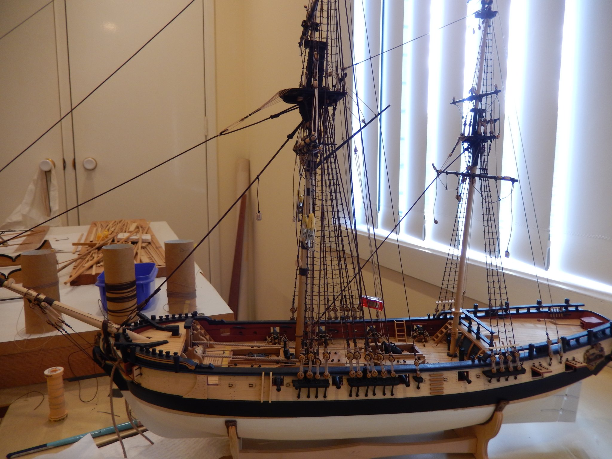
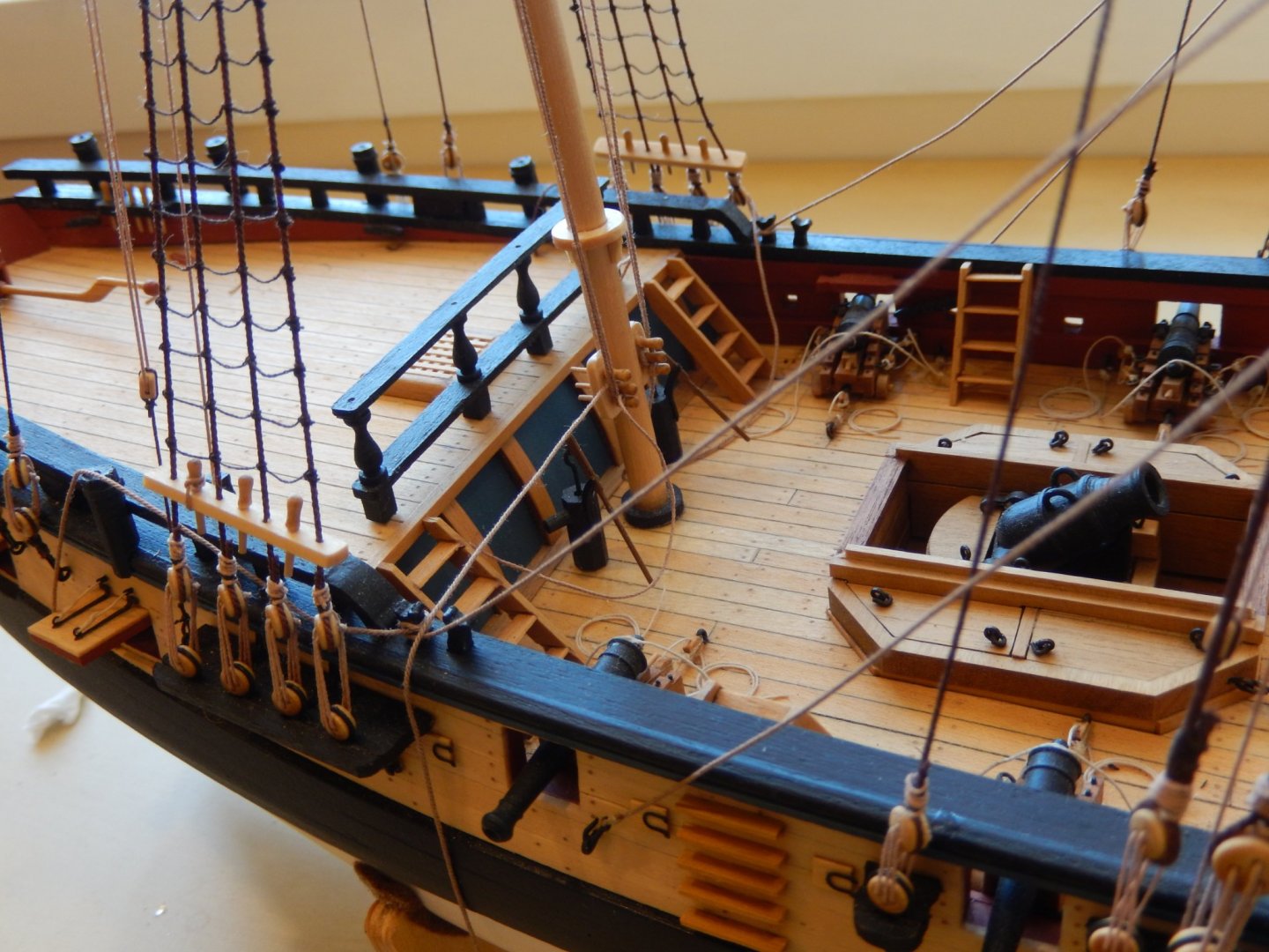
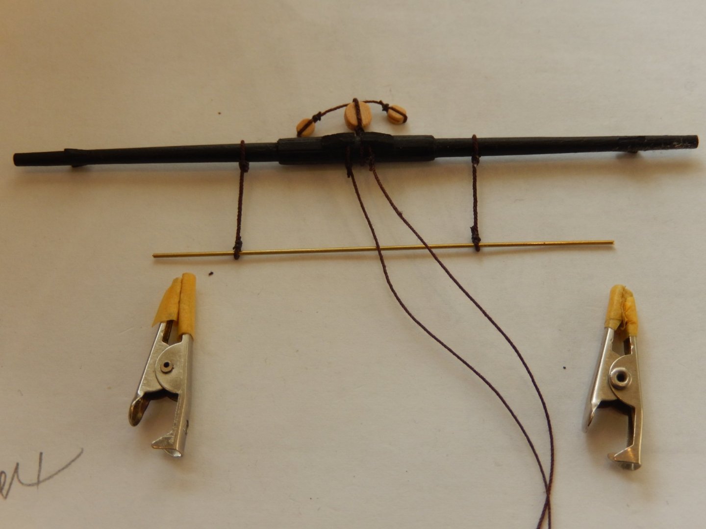
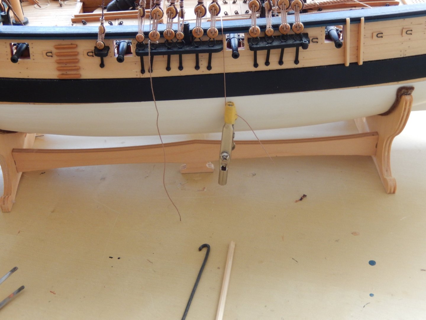
Here is progress, such as it is. Since my last post we've had storm damage to our house on the coast south of Sydney which has disrupted all sorts of things. What with the fires, our floods, the pandemic and the recent storms, we're now waiting for the locusts. The following photos are all a bit random. Instead of wire to support the foot ropes, I have used thread which more nearly approximates the real thing. To make them appear taught, dilute PVA has been applied and wire threaded though the holes for the ropes. Alligator clips have then been hung off the wire while the glue dried. Belaying ropes the appropriate points is often quite difficult. Here are the' tools' I used for the main yard lifts which are belayed to kevels - simply a piece of wire bent to be able to hook the thread and a bamboo stick with a notch cut in the end to push it. Manipulating them across the deck works a treat with weights on the end of the thread to keep it taught. This is the overall look at the moment. Unfortunately the light for photography was not all that good and doesn't show much detail - will try harder next time.


- 421 replies
-
- 14
-
-
- caldercraft
- granado
- (and 1 more)
-
Hardee ... : you have chosen quite a demanding model, particularly if this is your first attempt. Thanks for the kind words. If I can help you on the way, don't hesitate to contact me. Good luck. Bob
- 421 replies
-
- 1
-
-
- caldercraft
- granado
- (and 1 more)
-
Thanks Sam and Gahm. A bit of encouragement is always welcome. After all this, I think I'll take up modelling aeroplanes.
- 421 replies
-
- 2
-
-
- caldercraft
- granado
- (and 1 more)
-
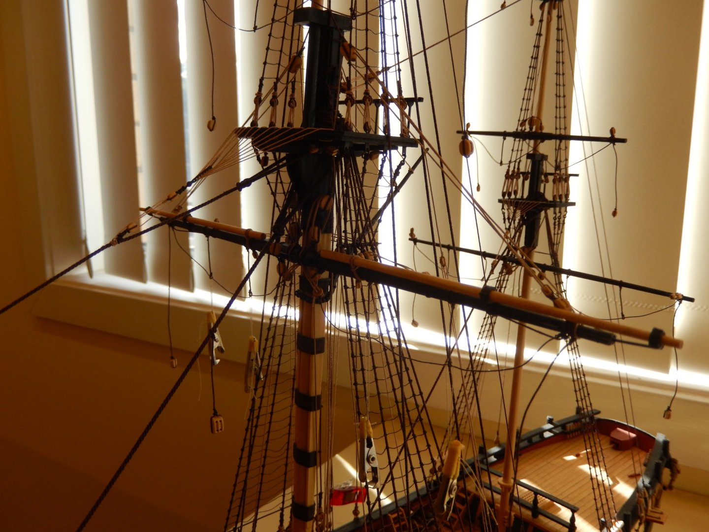
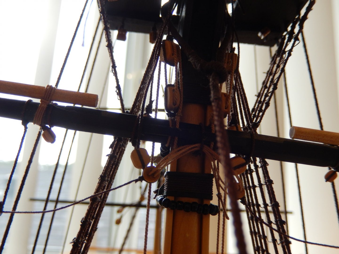
Obviously progress has been very slow - largely self-inflicted. The main yard has been a nightmare. A few things that I did some time ago have come back to bite. First, replacing the poor quality 1.5mm ply bibbs with 2mm strip. This of course meant that the mast is 1mm wider than specified. Second, the main stay is specified as 1.3mm thread. The Syren thread comes as either 1.14or 1.37mm. I originally chose the 1.14mm stuff. It was suggested (rightly) that the thicker thread would look more authentic. I then replaced the 1.14mm thread with the 1.37mm (which looked far better). However I eventually measured the 1.37 thread to be closer to 1.5mm. I then served the eye and the mouse which made the stay thicker still. All of this looked just fine. Now come the problems. The jeer blocks had been installed earlier according to specification. However with the extra thickness of the mast and the eye, the upper (double) block was fouled by the eye. The top blocks therefore had to be lowered. This meant that the blocks had to cut off, then replaced with longer drops - which turned out to be far, far easier said .... Moreover the thread for the falls specified as 1mm (I used 0.88mm) did not seat properly (it's quite stiff) and had contributed to the fouling. I replaced it with 0.63 thread which further improved things. Fortunately the change is not noticeable. In all, the overall result is reasonably adequate though I guess that's for others to judge. I see I have just duplicated the photo. I have no idea how. In no particular order associated bits and pieces. Below in the photo of the parrel, there is a small length of Tamiya tape attached to the thread which goes through the lower part of the parrel. This both prevents the whole assembly coming off in the process of installation and identifies that is the lower thread. (It's easy to mix them up.) With the crowded rigging around it, the installation is quite difficult. The yard rings are really quite poorly designed. To put top and bottom together reasonably securely and accurately, I ended up drilling holes in both, then inserting and gluing a piece of wire into the holes. For the end ring, again a hole was drilled, wire inserted and bent to the appropriate shape. Here is how they came out. Incidentally, for the foot ropes, rather using wire for the drops, I used thread, consistent with anatomy of a ship. Despite the photos the ropes now hang quite nicely.

- 421 replies
-
- 16
-
-
- caldercraft
- granado
- (and 1 more)
-
Thanks Thomas. I have friends in South/North Carolina and hope you are doing well too.
-
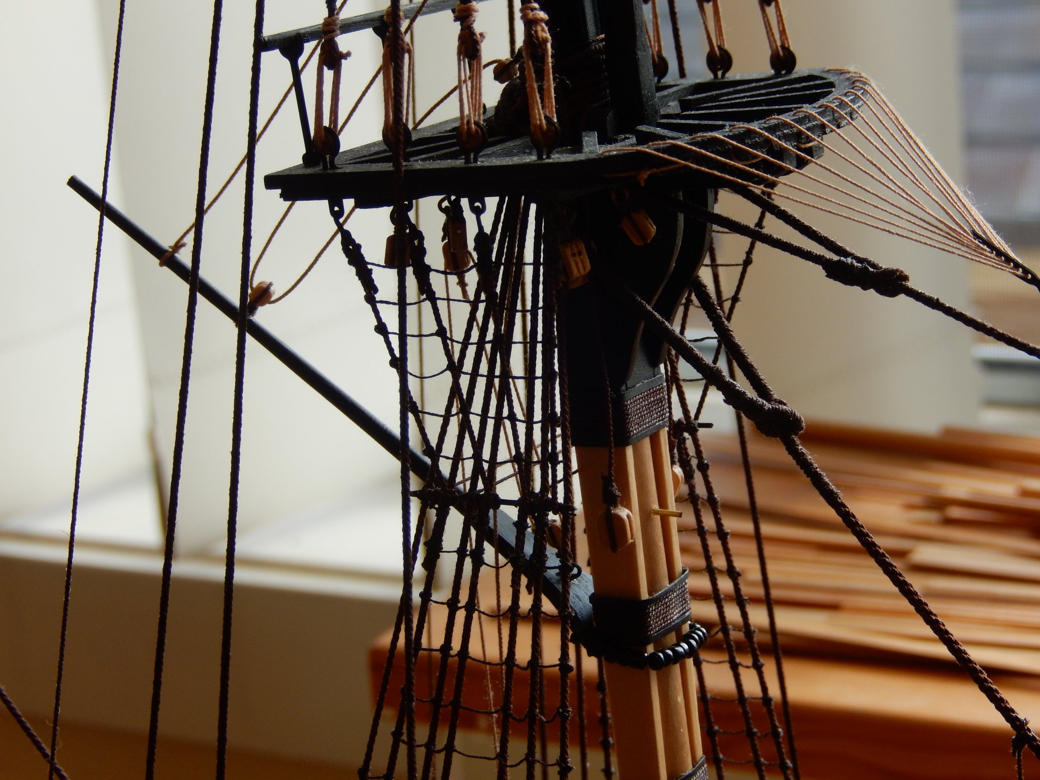
A delayed thank you Sam for the encouragement. Other things have intruded recently. I have now completed the wingsail gaff. I would not care to do it again. The fundamental difficulty is the lack of access, as it is surrounded by so much other rigging. I think there is a case for installing it, certainly before putting up the back stays, and even before the shrouds. Replacing the kit-supplied bibbs which are made of rather unattractive coarse grained 1.5mm ply, with 2mm timber turned out to be a lurking problem. The gaff jaws no longer fitted and then had to be adjusted. Access to the rear of the block on the top trestle tree for the 0.5mm thread proved to be very difficult indeed. I ended up threading some 0.1 mm thread through the front of the block, down to the the end of the 0.5mm thread, joining it with CA, then pulling the whole lot back through the block. As well, and VERY important, when installing the block earlier in the build, there is no indication that the thread initially leads down from the **** of the block. It therefore had to taken out of the trestletree (I found I had installed it all too well), the thread installed, and the block replaced. If you have to do all of this - good luck. Here are the results.


- 421 replies
-
- 13
-
-
- caldercraft
- granado
- (and 1 more)
-
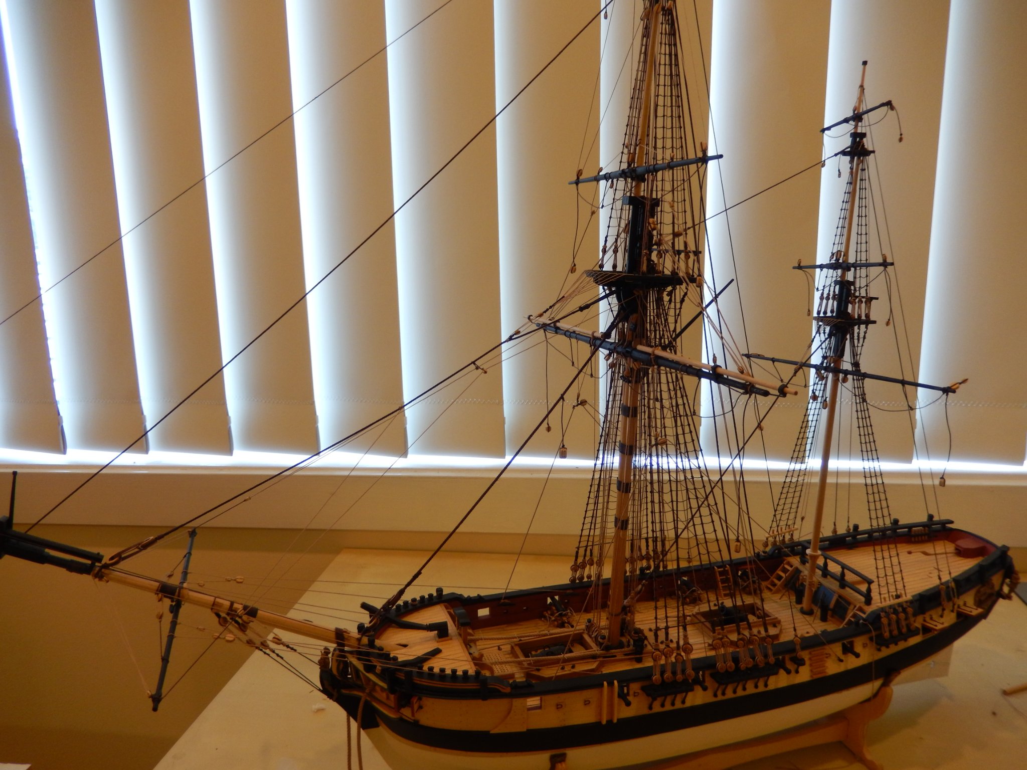
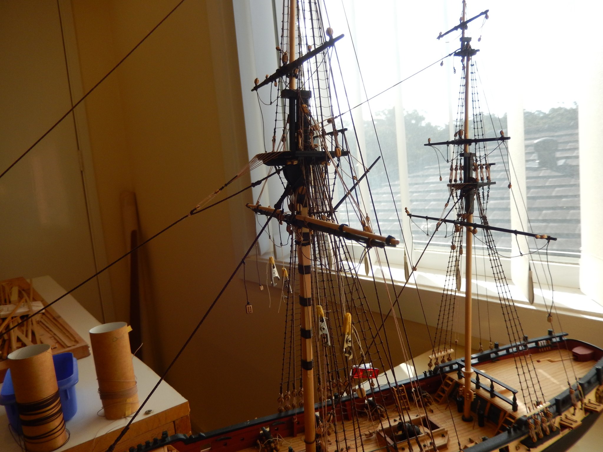
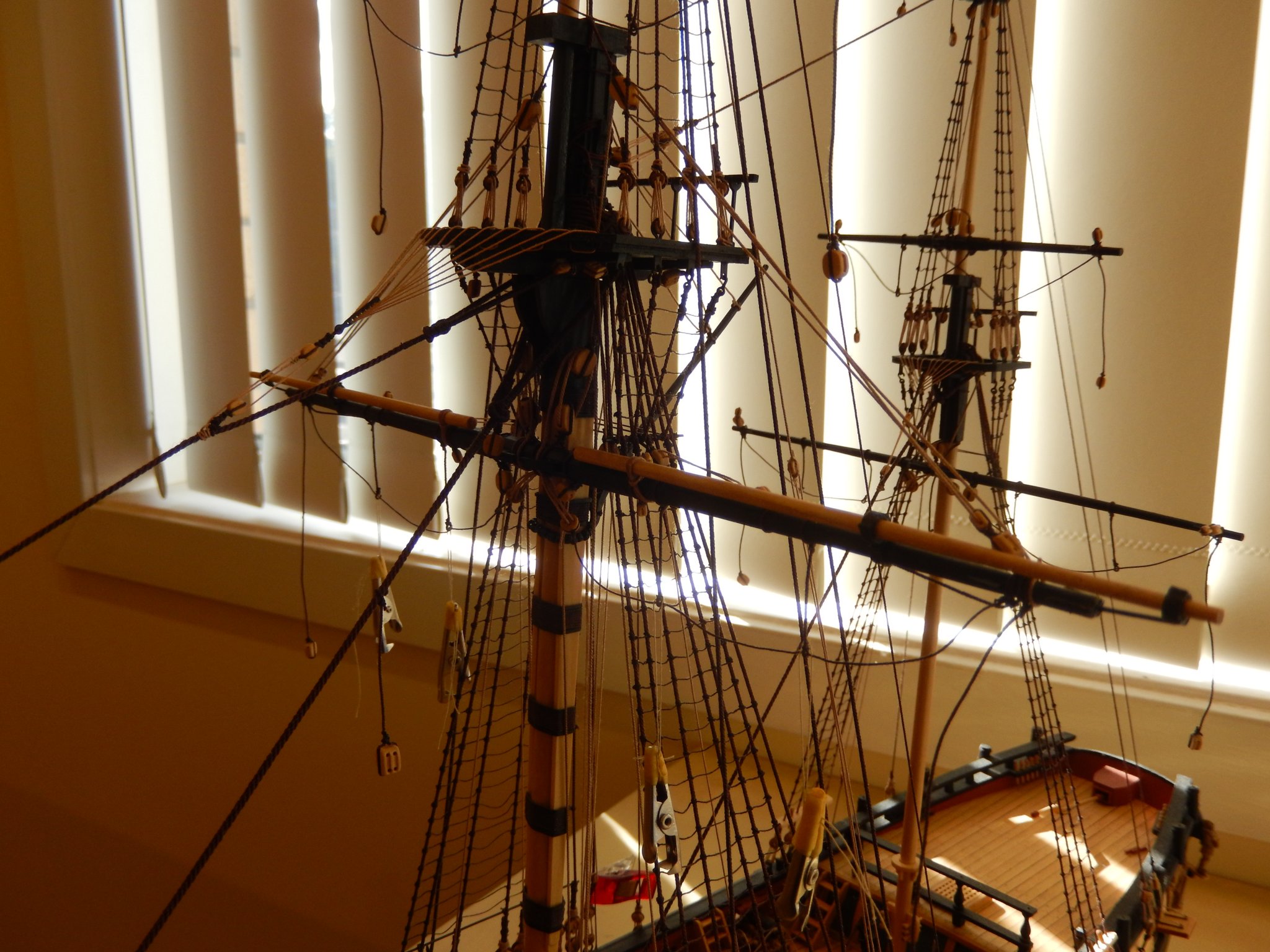
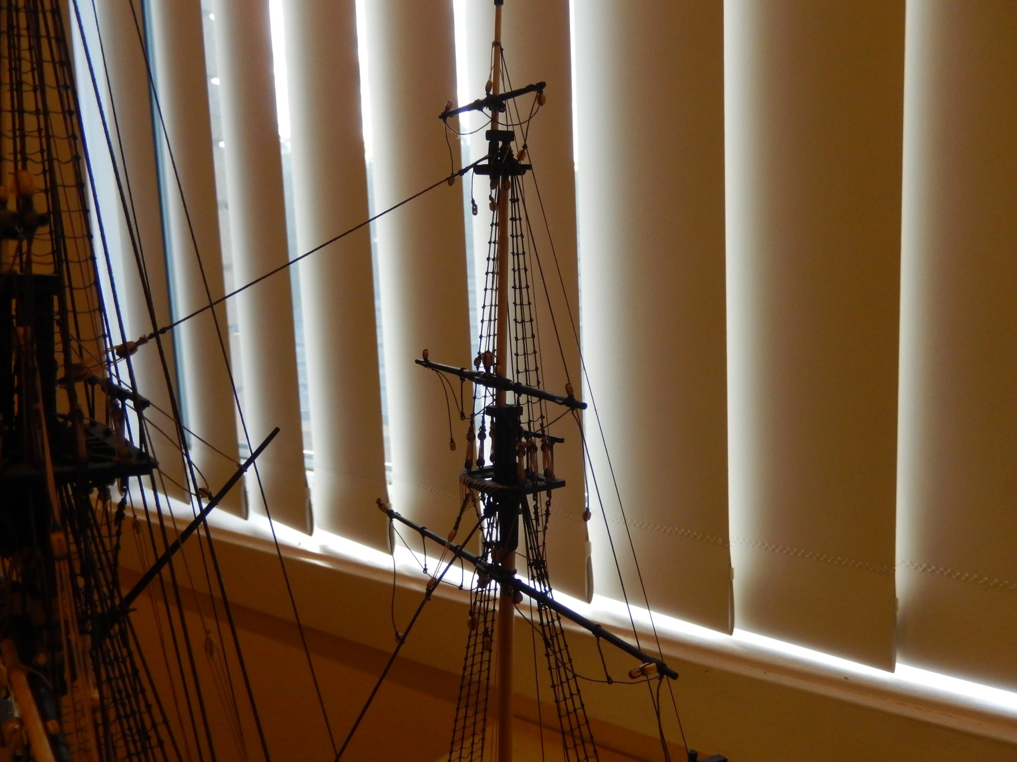
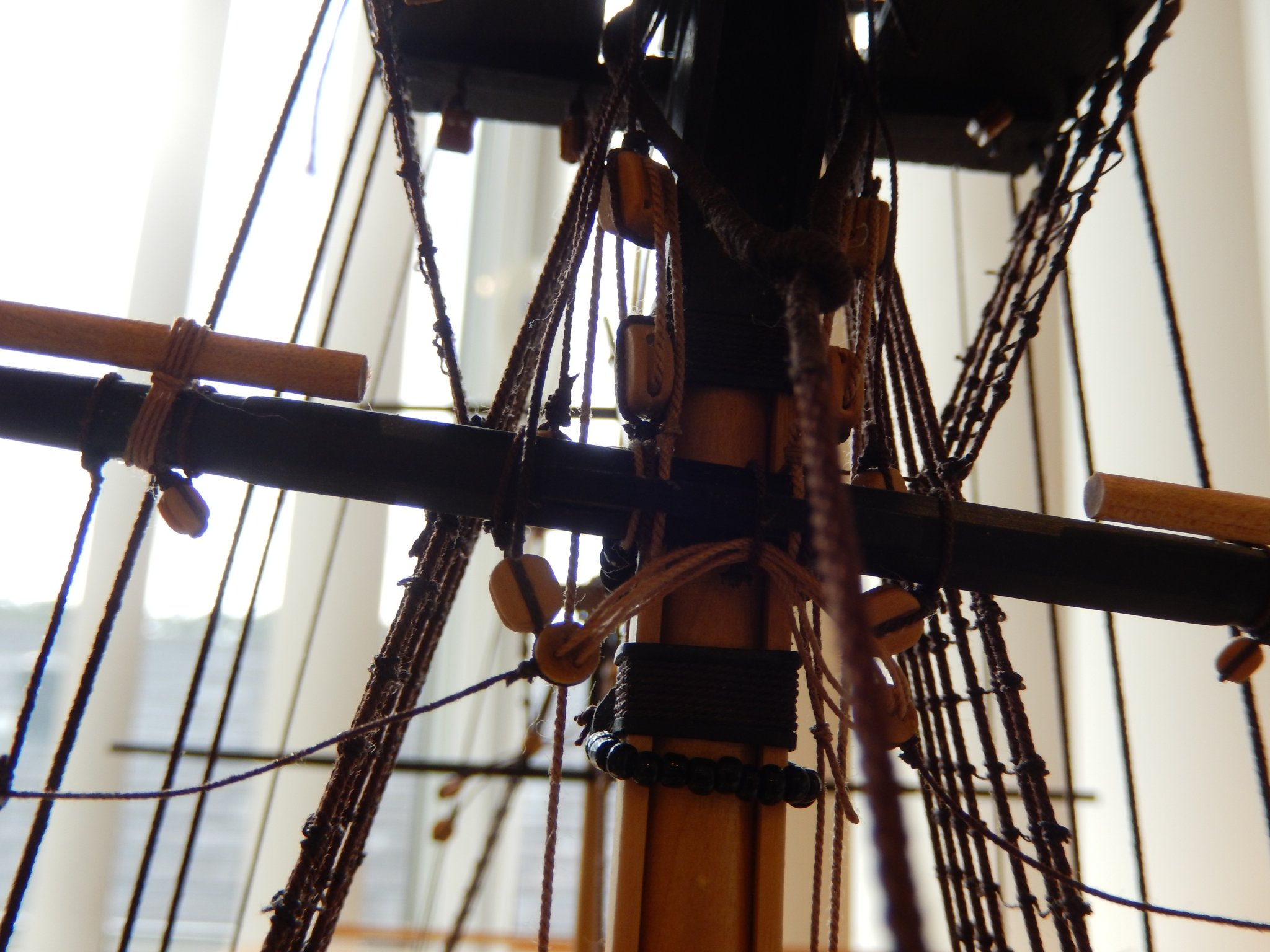
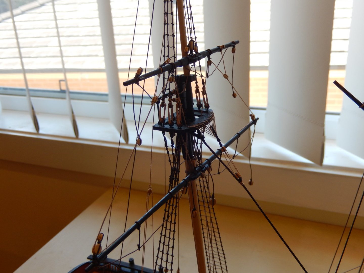
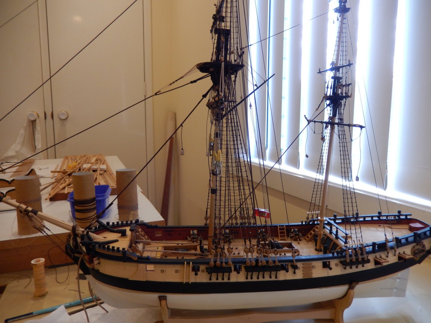
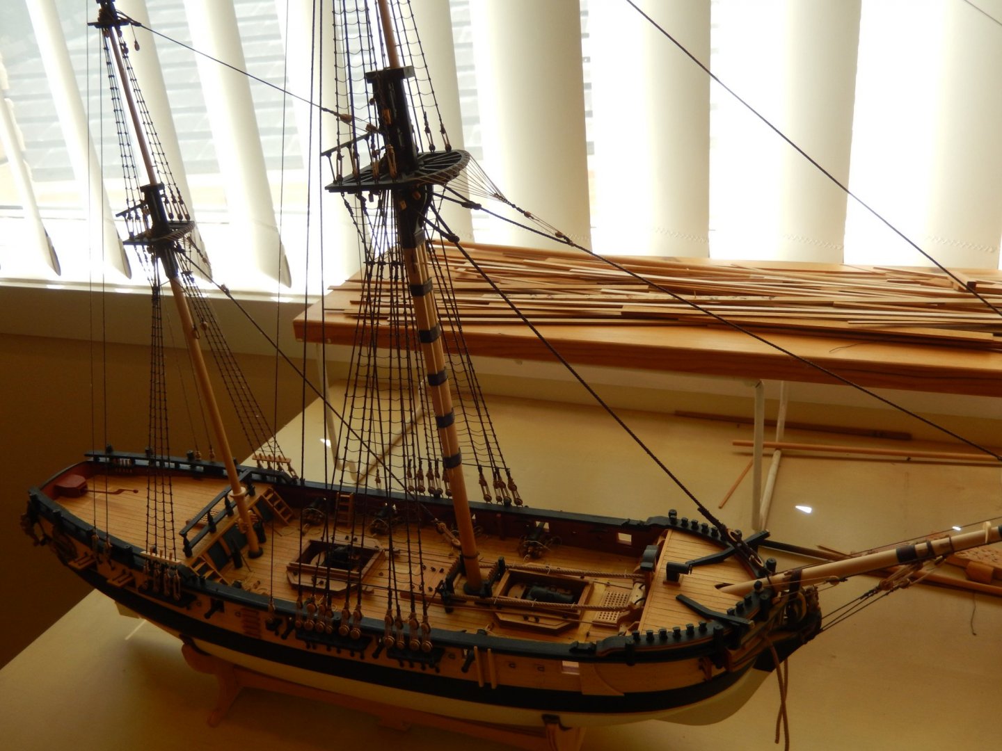
After a few setbacks (some self-inflicted) the standing rigging is finally finished. Next time I'll build a motor boat. Here is how it looks.


- 421 replies
-
- 12
-
-
- caldercraft
- granado
- (and 1 more)
-
Thanks Captain and Thomas. We can all do with a little encouragement now.
-
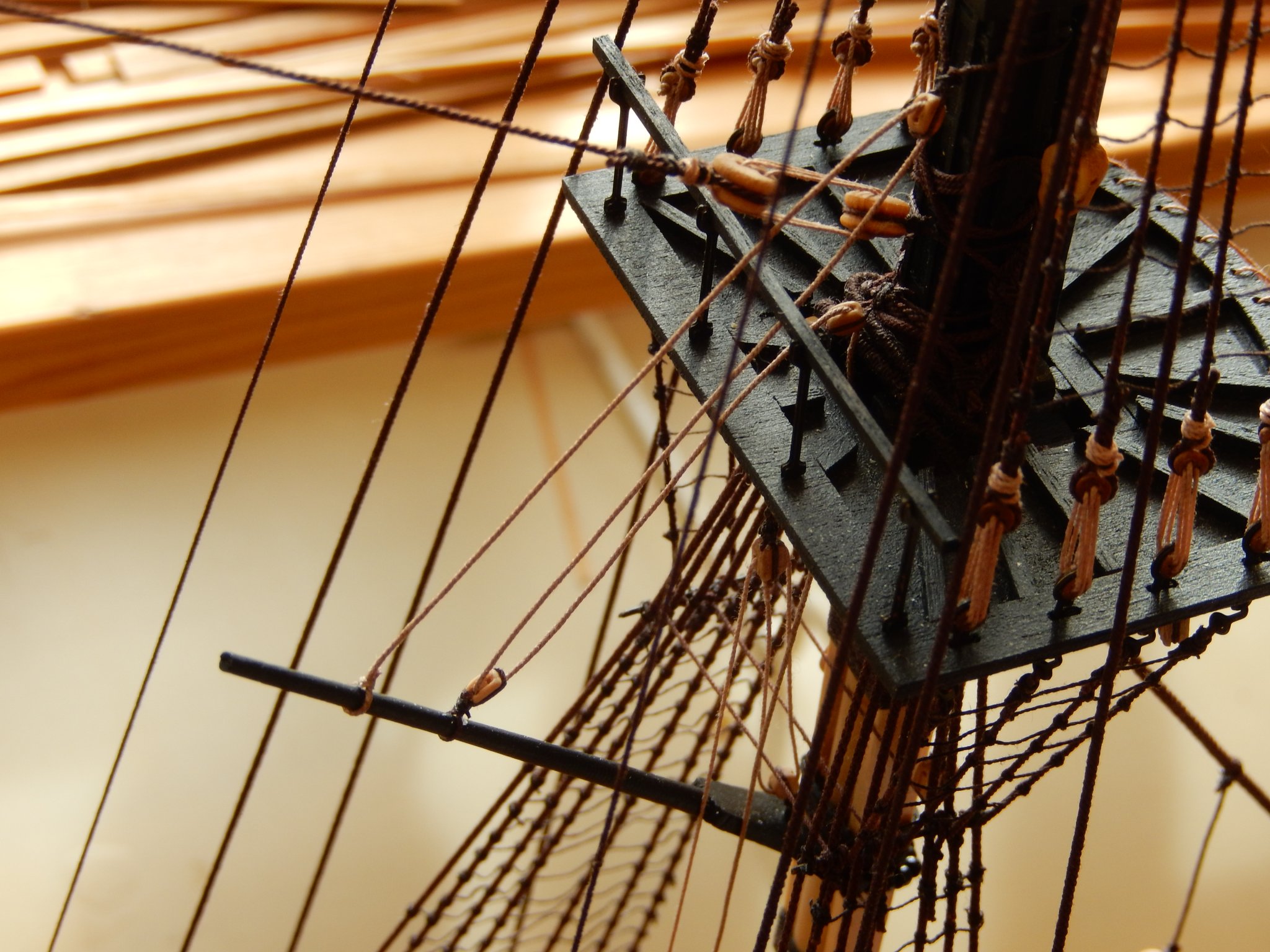
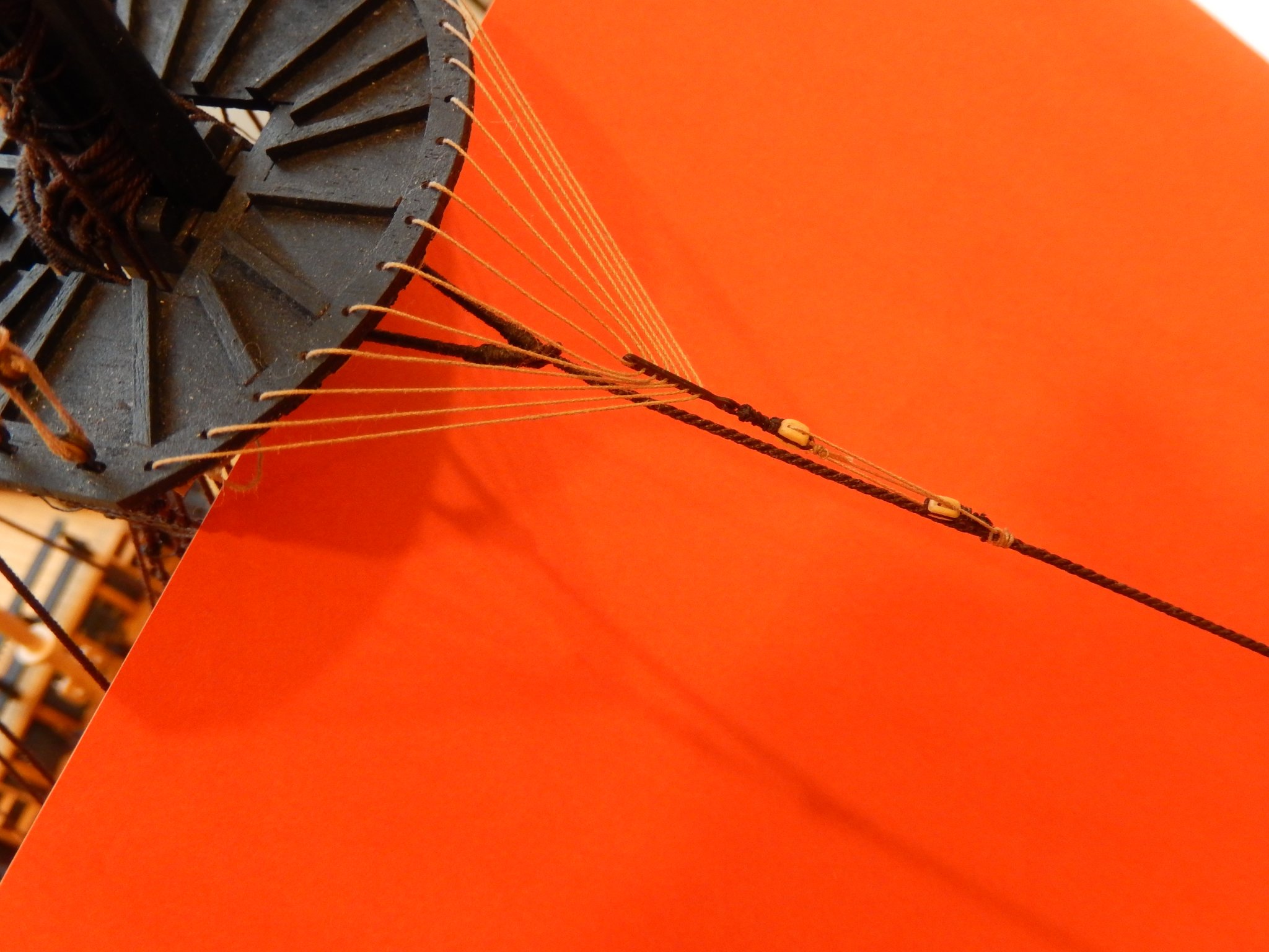
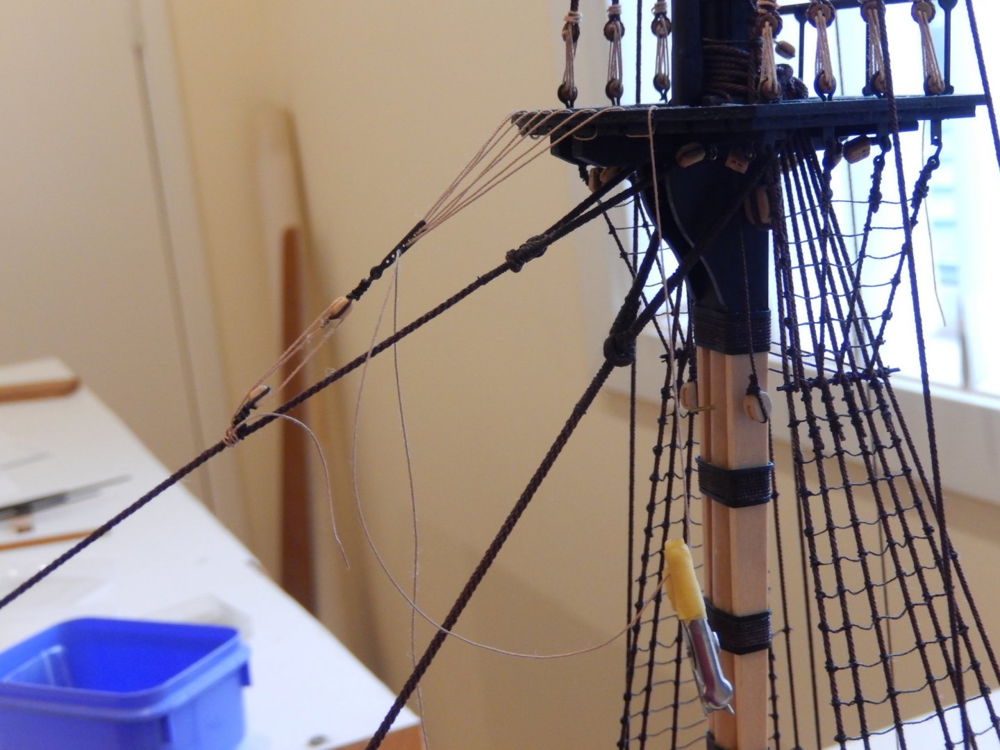
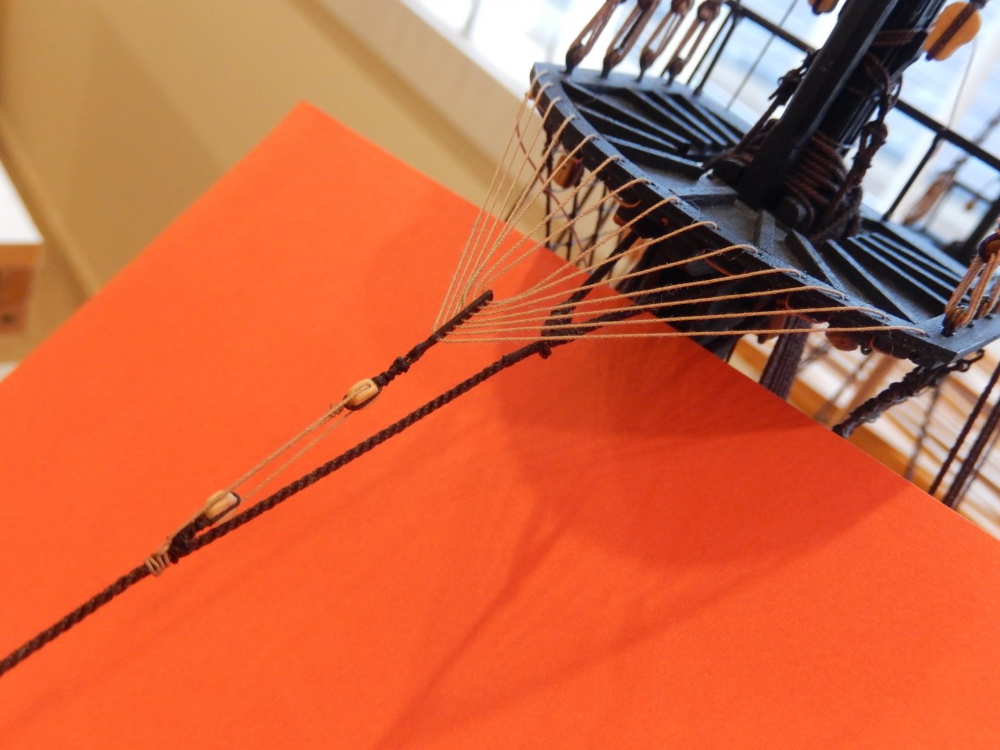
The crows feet on the main preventer stay is (are?) done. It's easy to damage things in the process and I'm relieved that it has come out quite well. I adjusted the tension of lashing as the rigging process progressed. The thread was kept taught by hanging a small alligator clip part way down the line while the end of the line was threaded through the euphroe or the top. It worked well. By the time all the lines were threaded, virtually no further adjustment to tension was needed here is how it turned out.

- 421 replies
-
- 9
-
-
- caldercraft
- granado
- (and 1 more)
-
Hi Peter Unfortunately you were right. First I replaced the 0.1mm with 0.2mm thread - didn't really make much difference - still not happy. I then went the whole hog; replaced the blocks and used 0.3mm thread. There is still the problem with the 1.14mm thread (rather than the specified 0.1mm) for the topmast stay. It looks bulky on the block, but the next thinner thread is just too thin. I'll just have to settle for happier.🙂
- 421 replies
-
- 10
-
-
- caldercraft
- granado
- (and 1 more)
-
My head's not too flash either Joe. Now if I could only remember what day it is ...🙄
-
Hi Peter I misinterpreted your comment on the 'tackle'. The instructions specify 0.1mm thread for the 3mm blocks. I too thought that looked a bit thin once I had rigged them. I had originally thought I would go with 0.2mm, but then I looked at the instructions. That'll teach me. It still may be possible to replace the 0.1mm. I will see what can reasonably be done.
- 421 replies
-
- 2
-
-
- caldercraft
- granado
- (and 1 more)
-
Richard?
-
Hi Peter The origins of the problem are the American dimensions of the Syren thread. The plans specify 0.75mm thread for the main top stay. In effect the Syren choices for 0.75mm thread are 0.63 or 0.88mm threads. I chose the 0.88mm. The 0.63mm is simply too thin. So if anything I have overspecified the rope. 🙂 The 0.88mm looks a bit bulky on the 3mm blocks ... but there you are.