jack.aubrey
-
Posts
1,268 -
Joined
-
Last visited
Content Type
Profiles
Forums
Gallery
Events
Everything posted by jack.aubrey
-
 Thank you Carl for your message, Jack. PS: I've seen you are building the Corel Dolphyn. I started it some time ago but at a certain moment I decided to stop with it. I sold it incomplete to another modeler in Venice. You can find my work, unfinished, here, although it's in Italian language there are plenty of images: http://forum.magellano.org/viewtopic.php?f=57&t=619 The hull of this ship is quite similar to the hull of my Brick and I got some useful experiences with it !!
 -
Many thanks to all of you for your support . . She was 94 years old and we all were aware that this will may happen sooner or later . . We are happy she didn't suffer too much. She miss us. Thanks again, Jack.
-
Wednesday, July 15, 2015 Since the death, on June 23th, of my mother-in-law, my wife and myself discovered that staying in Cinisello Balsamo we feel a bit alone. So, just to get some vacation, because it's more or less three years that in summertime we stay at home, we decided to move as soon as possible at our daughter's house in Calci, near Pisa, for some time. If all goes as we hope, in a couple of weeks we'll leave and it is very likely that we'll come back by end September. So I am faced with two choices: a- close the shipyard for some time or b- prepare the skeletons of the three ship boats before leaving and then, carrying with me the bare minimum, finish them while I'm away. Of course I selected the second possibility and in these days I am working to prepare the second boat scheleton and hopefully also the third, in order to continue elsewhere. Among other things I am not sure if I will get the internet connection because my "catastrophic" daughter has changed her provider with the result that her ADSL line is down without a planned availability date . . hoping in the near future. Finally: I got an answer from the photoetching guy who promised to send me a quotation for the next few days. Hoping in a positive and viable answer. See you soon, rgds. Jack.
-
Sunday, July 12th, 2015 Before continuing with the planking I proceeded to apply mahogany mordant to the keel and the bulkhead complex. In the photos it seems pretty dark. . in daylight it's a bit better. Considering this Sunday there are many motorcycle races (Moto3, Moto2 and MotoGP) on the TV, I postpone further activities for tomorrow. 01 Brick%20by%20JackAubrey/20150711_120725_zpsvez3q67j.jpg 02 Brick%20by%20JackAubrey/20150711_120713_zpsdilsn1iw.jpg 03 Brick%20by%20JackAubrey/20150711_120624_zpsstjvehqi.jpg Best regards and see you next, Jack. ****************************************************************************** Many thanks, really appreciated, Jack.[thumbup]
-
Hi Anobium/Christian, thanks to your offer to help me with german language. This is another option I can add to my choices basket. Be sure I'll contact them, and if necessary, I'll involve you. Thanks again. Jack. Saturday, July 11th, 2015 For the moment I have installed the keel on the bulkheads . . I'm waiting for the glue to dry. In the meantime I prepared two mini wood blocks to shape the bow. They are so "big" that I had to fix them on a piece of wood to be able to work with them . . I then began to cut ten/twelve strips of Tanganyika from a sheet of veneer. 01 Brick%20by%20JackAubrey/20150710_113827_zpsdenmzwle.jpg 02 Brick%20by%20JackAubrey/20150710_113812_zpsp7zg4mi4.jpg 03 Brick%20by%20JackAubrey/20150710_113750_zpsoqybwc6t.jpg 04 Brick%20by%20JackAubrey/20150710_113804_zpsnbenchh3.jpg Rgds, Jack.Aubrey.
-
Is your Saemann the same Saemann I find in this web site ? http://www.saemann-aetztechnik.de/ If yes, I'll keep it with my options for the search. Did they speak/write in english ? Many thanks for the infos. Jack
-
Friday, July 10th, 2015 After a long break due to family problems and, last but not least, thanks the hot weather of these last days where I live, finally yesterday and today I was able to resume activities on the model. Being for now suspended any task on the brick hull, waiting for news regarding the copper plates, I started the construction of one of the three lifeboats carried by this ship. In recent days I spent enough time designing plans with AutoCAD and now in theory the three boats are ready to be built. The design method is the same for all, then, to avoid that an error is reflected on all the three projects, I decided to start to build only one for now. Later, if the method will work, I will start the other two, otherwise I will have to correct something before proceeding further. The choice is obviously fallen on the largest boat: being larger it should be easier to work with. . The first image shows all the pieces cut and finished, after I glued the AutoCAD printouts on a birch plywood, 5 layers, 2mm. thickness. The metric scale in the background should give a idea of the size of this boat: about 16-17cm. Shown below is the mounting basement, consisting of a plywood tablet on which has been glued a boat plant. On the centerline is a strip of 5x5mm. intended to keep the bulkheads capsized but aligned. 01 Brick%20by%20JackAubrey/20150709_185229_zpsgbqkmzvn.jpg After removing the paper from all the cutout pieces, I started the actual installation just glueing all the bulkheads. The alignment is obtained with the 5x5 strip on the base. So far everything seems to work well. With a special tool of adequate size, I made me sure to glue the frames perfectly vertical with respect to the base. So far, so good. The next two images show the work at this point of the installation. 02 Brick%20by%20JackAubrey/20150710_105949_zpsgmkqv3ay.jpg 03 Brick%20by%20JackAubrey/20150710_105940_zpsa0kprqd1.jpg The work is still in progress, see you soon, Jack.Aubrey.
-
Hi Fam, it's a matter of points of view. Personally I prefer to take care of something useful to me tomorrow, like the copper plates, than something that will probably need me, considering my slowness in this hobby, within one o more years. A house is built starting from the basis, not from the roof . . Cheers, Jack.
-
I'm trying to survive although it's very difficult . . Regarding shipmodeling I'm idle, waiting for better weather conditions. I visited Eduard website and I found something like more 100 pages of photo etched details, mainly for aircrafts and grey ships. Nothing about period ship models. Anyway I'll try to contact them to understand if they can arrange customized productions. I'm also waiting for answers from some italian companies. How do you plan to arrange the copper plating on your model ? Are you available for a joint venture, provided I'll find a supplier ? Rgds, Jack.
-
First I want to thank Mtaylor and aviaamator for their suggestions: I'm now still looking on the Italian market of photoetching companies but may be your suggestions will become useful if I'll not find an opportunity in my country. I was inspired for my copper plates solution to Mikhail Bezverkhniy's "Rivoli" and Alex Baranov's "Cumberland", here below an image of the "Rivoli" copper (?) sheating Sunday, July 5, 2015 Still nothing new, except that I progressed the design of the shipboats. In this message I intend to post the plans of the "intermediate" ship boat, which should be installed over the main deck inside the larger one. In the first image the basic design, obtained by tracing the ANCRE plan with some adjustments where they seemed necessary. 01 Brick%20de%2024%20Plans/v1.0.0.ScialuppaMediaDisegno1_zpsyspa5kvw.jpg Then follows the side shapes. . 02 Brick%20de%2024%20Plans/v1.1.0.ScialuppaMediaDisegnoLato_zpsl6kfomk1.jpg The profile of the keel. . 03 Brick%20de%2024%20Plans/v1.1.0.ScialuppaMediaDisegnoChiglia_zpsxe94dntj.jpg The bulkheads from amidships to bow. . 04 Brick%20de%2024%20Plans/v1.1.0.ScialuppaMediaDisegnoPrua_zps5iyjtesq.jpg And the bulkheads from amidships aft. . 05 Brick%20de%2024%20Plans/v1.1.0.ScialuppaMediaDisegnoPoppa_zps4xrw13wd.jpg 06 Brick%20de%2024%20Plans/v1.1.0.ScialuppaMediaDisegnoPoppa2_zpsexak99kc.jpg The images you see here are not to scale because the forum software resizes them in its own way, but you can download them by clicking on the image and then proceed to its download at 1:1 size. Sincerely, Jack.Aubrey

-
Sunday, June 28, 2015 Still a long period of inactivity regarding my shipmodeling activities. Too many bad things happened in this month and so I could not continue working on my model. Only sometimes I could dedicate to it and this exclusively via AutoCAD in designing two of the three ship boats. I have already shown the greatest, the longboat, which should allow me to cut out the pieces to setup the hull and now I could begin its construction. . but i'm not sure this will happen shortly. Then, I continued with the smaller lifeboat: the same type of work and now I have ready the preliminary project to build it. The thrid boat, the last, is still missing. Finally, I continued to work on my idea of a "different" solution to the copper plating of the hull. I reached the conclusion, may be right or wrong but for me should be the one with a better aesthetic result and process, that the best copper plates to be applied to the hull had to be obtained through a process of photoetching combined with a laser cutting. In Italy there are several companies that provide this service. I found some time ago one conmpany on the internet that seemed to have the right requisites and I proceeded to contact it. Unfortunately they said that, although it is possible for them, they do not make business with privates and the business aborted. So now I have to re-initiate a search until I found someone who is willing to do this work. Meanwhile, given that the whole process of photoetching generally starts from a vector file (can be done, for example, with AutoCAD), I proceeded to draw a copper plate of the correct size with all the nails planned in the original plate, shown here below in a visible size. 01 Brick%20de%2024%20Plans/V1.2.0.PiastraRame_zps6spskkxo.jpg I then proceeded to prepare the vector file in A4 format including the maximum containable number of plates, both for the right side of the hull than for the left side. Here you can see the result. Everything should be photoetched and laser cut from a sheet of copper or brass (after year 1800 was no longer being used only pure copper but copper alloys with other less expensive metals) of the proper thickness, to be better defined with the photoetcher, but which should probably between 0.1 and 0.2 millimeters. 02 Brick%20de%2024%20Plans/V1.2.2.PiastraRameA4Lato1_zpstty7dvyx.jpg 03 Brick%20de%2024%20Plans/V1.2.2.PiastraRameA4Lato2_zpsxqelro85.jpg The story is still far from its end anyway, because if I do not find the photoetcher I'm lost. Does anyone know one in Italy or in Europe ? Cheers, Jack.Aubrey.
-
Saturday, June 20th, 2015 The last missing elements of the brick longboat plans: the bulkheads from amidship to bow. Now in theory I could start its building using the idle periods of time of the main project. Cheers, Jack.Aubrey. 01 Brick%20de%2024%20Plans/v1.1.2.ScialuppaGrandeDisegnoPrua_zpssrg1vkjy.jpg
-
Friday, June 19, 2015 It's +/- fifteen days that I do not provide any news about this project. Unfortunately I had other commitments and could not find the time to continue with my idea on the copper plating. Commitments about matters concerning the condominium where I live, so I was heavily involved and I am just now released. I also had to undertake the repair of my computer because the two internal harddisks showed signs of being to pass away and I had to recover the situation. As result I spent almost three full days to restore all the data on the new harddisks. Thanks to the fact that I have always had in place an automatic and regular data backup process I did lose practically nothing. But I had to reinstall many software, from Windows 7 Operating System to the application programs I usually use. It had also a chance to do some housekeeping of all the "garbage" installed in the last five years. Now, thanks to the smart hardware changes, the PC runs like a beauty. And so, rather than carrying on the copper plates matter, since I was on the computer many hours, I started thinking to get ready to build, at the right time, the brick longboat, the first of the three boats on this ship. And here I followed the same path that led me to design the hull of the ship some months ago: 1) trace the longboat ANCRE plan with AUTOCAD, 2) correct some more evident errors in the drawing, which, as far as great, was convenient to adjust. The result can be seen in the first image here below, containing all the hull design elements. 01 Brick%20de%2024%20Plans/v1.0.0.ScialuppaGrandeDisegno1_zpsgtelmm2d.jpg From the first drawing I then extrapolated some details, as the following views . . 02 Brick%20de%2024%20Plans/v1.1.0.ScialuppaGrandeDisegnoLato_zpsthsqaani.jpg Then I cleaned up a few lines that were no longer needed . . 03 Brick%20de%2024%20Plans/v1.1.1.ScialuppaGrandeDisegnoLato_zpsefmj0pri.jpg Until I got the draw of the keel . . 04 Brick%20de%2024%20Plans/v1.1.2.ScialuppaGrandeDisegnoLato_zpsxwvbohjf.jpg And the bulkheads from midships aft . . 05 Brick%20de%2024%20Plans/v1.1.2.ScialuppaGrandeDisegnoPoppa_zpsewgrx39p.jpg The process continues . . Cheers, Jack.
-
Thursday, June 4, 2015 First, I state having nothing new to show and I'm waiting to meet this evening with some other modelers to discuss my idea, so I limit myself for now to show two pictures trying to comment them. The first image refers to a tool produced by Amati with a clear aim to simulate through punching on material like copper or similar studs the copper plates. It's sold with four pouncing wheels with different pitch in order to be used in different scales. A useful tool even if it should not be difficult to scratch build . . depends more on its costs. 01 Pounce Wheel.jpg The second image, instead, makes us goback to the messages regarding the USS Constitution after her entrance into the dry dock. The photo here below shows the appearance of the copper plates when, back in 1995 (see the date on the photo) were completely replaced and shortly before her return to the sea. I think with this last image you can better evaluate the changes intervened during her period in seawater. However it is not polished and reddish copper but tending to brown. Obvious as this is what happens to the air and the 3400 copper plates were certainly not produced the day before, then some kind of oxidation should be underwent. 02 1995-const-sternview-e1431367120505.jpg See you soon, Jack.
-
Hi Yves, I have several fig trees in the garden (it's not mine but from my motherinlaw) and they produce several fruits . . . But unfortunately they don't ripe: they are all lost during their ripening season. I believe that in order to get some good figs I should graft them with other braches from certified trees . . If have also a grapefruit tree and this is another matter: every year provides a good production of fruits, lets say from twenty to forty kilos of fruits depending of how good was the season. Regards, Jack.
-
Monday, June 1, 2015 A cordial greeting to everybody. I thank all the forum users for their comments and advices to my messages concerning the upcoming activities. Unfortunately, in the absence of further developments "on the field", I come to propose further model images that date back a few days ago. The fact that I haven't done anything "practical" in the last days does not mean that I have been totally idle, I simply continued my search for an optimal solution of how best simulate the hull plating with copper. At the end (really ?), after many considerations, surfing the internet here and there and activating some other sources, I come to identify a solution that, if should prove to be viable, would become in my opinion the most valid. Now I am engaged to carry out the necessary checks this idea can be really pursued. In the next post I'll try to explain better the idea and, in the meantime, I hope to confirm its validity, especially the feasibility. For now, enjoy the pictures. Regards, Jack. 01 Brick%20by%20JackAubrey/P1100276_zpsg9mlx6or.jpg 02 Brick%20by%20JackAubrey/P1100284_zpsog3lwhn6.jpg 03 Brick%20by%20JackAubrey/P1100281_zpsdfjdcwge.jpg 04 Brick%20by%20JackAubrey/P1100270_zpsyq8orfvd.jpg 05 Brick%20by%20JackAubrey/P1100271_zpsgjz85psd.jpg
-
Hi Fam, while I'll perform the hundred tests planned for the copper plates etc I'll surely find the time to add the missing blocks . . Cheers, Jack.
-
Hi Mark, I agree with your comment . . the final decision on how to show the model is mine. I wrote about my intention to pursue the copper sheating challenge and this is still my primary idea. But I need to define the correct method and for this reason I'm preparing to test and evaluate several paths before selecting the best for me. In the worst case, if all the objectives of my tests will fail, I'll can change my mind forgiving copper and adopt the wood finish . . but with a good reason ! For now I'm interested in understanding if the example of the Constitution copper plates may be considered as an accepted proof of evidence or not. If yes, as you have written, this should be my preferred choice: I want to build a Royal Navy french captured brick, so we are speaking about a ship that was in water for some years. Regarding how to obtain the green copper, it's again a matter of tests but I have at least two ways: a special varnish, I found on the internet, to apply over the copper and a suggestion form a friend of mine that made this experience using winegar and original sea sand. Again further ideas on how to obtain green copper are welcome . . and again thanks for your answering. Cheers, Jack.
-
Saturday, May 30, 2015 Honestly I expected some reactions/comments to the subject I introduced in the previous messages regarding the appearance of copper plating. . . but probably I was wrong. Patience. Meanwhile I finished the activities that were ongoing, including the installation of the gunwales. Now I think I must invent alternative tasks to perform while I'm preparing for the application of the copper. YES, because I decided to proceed in this direction. It's challenging !! I still have to procure the needed materials: I haven't a clear solution so I decided to buy tapes and sheets, self-adhesive and raw, of various thicknesses to do some comparative tests, then I will choose the solution that will give me the better satisfaction. While waiting I could start something that will be useful for the future, such as ship boats or some superstructures, I need to think about it. Besides, I should definitely level with sandpaper and finish the hull, also preparing the surface of the quickwork that will receive the copper. 01 Brick%20by%20JackAubrey/P1100282_zpsqkbwiaiy.jpg 02 Brick%20by%20JackAubrey/P1100280_zpspvzt80my.jpg 03 Brick%20by%20JackAubrey/P1100279_zps5zl9uvgm.jpg 04 Brick%20by%20JackAubrey/P1100277_zpsdftzvkhe.jpg 05 Brick%20by%20JackAubrey/P1100274_zpsotprofr3.jpg Further images from different viewpoints will follow . . cheers, Jack.
-
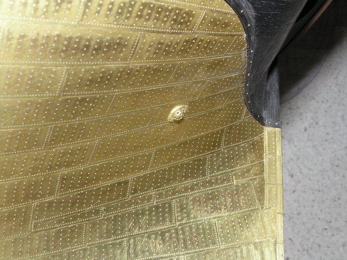
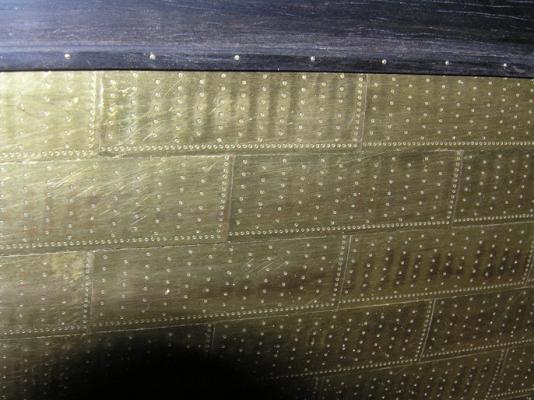
Wednesday, May 27, 2015 In these days I finished to install the gunwales and, as a final touch, I also gave a few black coats to them, so that now probably show an almost final appearance, unless new elements will be added in the future. Now I got to a state where it is no longer possible to stall further the project: 1) proceed with a natural wood finish of the hull and go further with this modelling presentation philosophy, often adopted by several ship modelers, or proceed with the installation of the copper sheating on the underwater surface, opting in this case for a more realistic way of presentation. If I should adopt this second solution I should obviously setup a surface preparation of the hull rather different from the first case. Then we need a strong decision. Regarding the first solution I had many experience, so it does add virtually nothing to my experiences because this would be a mere repetition of tasks already done. For the latter, however, it would be the first time that I face such a serious commitment. I did a small experience when I covered the underwater hull of the cross section model of the Santisima Trinidad with copper plates, but it is too simple and small compared to what I'm expecting now. However even this minimal experience with the SST left something to me. More about this later in this message. In fact it is several days that I'm on this subject by relating with other friends (and other I still have to do) and I also spent hours on the web to see what, how and who has already made similar experiences. I picked up a good portion of these "discoveries" in a document that describes these methods (a kind of patchwork picked from various sources), but they are still far from my complete satisfaction to have everything right and clear. Let's start for example from some methods of how to perform copper sheating. First you need a proper preparation of the ground surface in order to facilitate the application of copper and improve durability. Then the practice suggests two equally viable paths: - Use bricks made of copper in proper measure and apply them one by one according to a default scheme or - prepare copper strips on which are pre-cut more bricks and apply it on the hull in a more efficient way then previously. The fixing can take place using glue (cyanoacrylate or epoxy) or using copper already equipped with an adhesive film, used in some hobby decorative tasks. In addition there is the problem of the simulation of the riveting, topic still faced by many modelers with different methods but all quite effective. The copper support that can be found in commerce is of two types: tape or sheet, both self-adhesive or not. The tape media is very easy to find in its self-adhesive form but is also available in natural form. The real limitation here is that the choice of the height is limited (5,6,7 etc) so if you find the right size to fit is fine, otherwise you have to compromise on the measures. Even the copper sheet is marketed self-adhesive or not; I think that the sheet allows to make the right measurements of the individual bricks corresponding to the real original size, so I think this solution would be preferable. Finally, assuming that we have finally achieved to fully cover the hull in one way or the other we are faced now with how to display it. And here it is necessary to make some assumptions. From my experience with the cross section of the Santísima Trinidad I found that the copper, not treated with paint, left exposed to light and air, with time loses the original reddish brilliant color of the new copper and turns brown, getting darker, up to become almost black. To date, after three / four years, the color of my cross section is yellowish brown. Treating the copper with a glazing paint fixes permanently the beautiful color of new copper. . but is it realistic? But how becomes the copper in the absence of air under the water, in particular seawater? To hear somepeople the lack of air should prevent the copper from oxidizing and so the color would not change, others, instead, believe that there is still enough oxygen in the water to produce certain effects, in addition there is also the presence of salt water . . A topic of a forum addresses this topic http://modelshipworld.com/index.php/topic/8972-copper-plating-to-look-like-c-morgan-by-modelshipways/and it seems convincing. . And here enters the USS Constitution. As you have read in my previous messages, this sailing ship was lastly covered with copper plates in 1995 and until a few days ago has always been in water. So if we take for example the images below showing the copper appearance after twenty years we have an unequivocal and indisputable evidence of what happens to copper when it stays in seawater for a long time. Conclusion? Well, I leave this task to you, maybe, after having a deep look to the images that I propose here below, you will have the answer to the question with which I finished my prev message about Connie: "I'm sure you're probably wondering: which relationship has this message and related images with the Brick I'm building and that headlines this log ? At first glance, you'll see nothing but, with a little of patience this news, by the way quite recent and do not know how familiar to many people may it be, has veeeeeery muuuuuuch to do with my model under construction. A few patience for now." 01 USS.Constitution.in.Dry.Dock 12.jpg 02 USS.Constitution.in.Dry.Dock 20.jpg 03 USS.Constitution.in.Dry.Dock 13.jpg 04 USS.Constitution.in.Dry.Dock 21.jpg 05 USS.Constitution.in.Dry.Dock 22.jpg 06 USS.Constitution.in.Dry.Dock 6.jpg 07 USS.Constitution.in.Dry.Dock 10.jpg 08 USS.Constitution.in.Dry.Dock 7.jpg 09 USS.Constitution.in.Dry.Dock 11.jpg 10 USS.Constitution.in.Dry.Dock 19.jpg Comments? Other points of view or ideas ? Every comment is more than welcome. Regards, Jack.
-
Hi Yves, you are quite close to the true: I'm sure the next images I'll present and discuss in the forum will clarify very well some points related to the real appearence of the copper plating after many years in the salt water . . Today I'm too busy to post new messages, but I'll come back to this topic ASAP. Cheers, Jack.
-
May 19, 2015 6:35 AM USS Constitution Enters Dry Dock for Three Years of Repairs. By: Sam LaGrone Connie 1.jpg USS Constitution prepares to enter dry dock on Monday. US Navy Photo The U.S. Navy’s oldest commissioned warship is now in dry dock for three-year renovation, the service said on Tuesday. USS Constitution — commissioned in 1798 — entered Dry Dock 1 at the Charlestown Navy Yard early Tuesday where the ship will be renovated for a scheduled maintenance availability originally scheduled in March but delayed due to the severe winter weather on the Northeast in the earlier part of the year. “We couldn’t have asked for better weather or better support from the dedicated team of professionals who helped with the docking,” said Cmdr. Sean Kearns, USS Constitution’s 73rd commanding officer in a statement. “We’re now positioned to carry out the restoration work which will return Constitution to the water preserving her for the next generation of Americans to enjoy and learn about our nation’s great naval heritage.” The $12 to 15 million restoration will preserve and repair the 2,286 ton ship from the upper masts to the waterline and is scheduled to be completed by 2018. Connie 2.jpg USS Constitution passes by downtown Boston during the ship’s Independence Day underway (US Navy Photo) “The ship was made famous in the War of 1812 following several engagements with the Royal Navy earning Constitution the nickname ‘Old Ironsides’,” USNI News wrote last year following the ship’s last underway before the repairs. “Since then the ship has remained in commission undergoing several renovations and crewed by about 50 active duty U.S. Navy sailors.” The work to be conducted on the ship, according to the Navy includes, includes: * replacing lower hull planking and caulking, * removing the 1995 copper sheathing and replacing it with 3,400 sheets of new copper that will protect the ship’s hull below the waterline, * replacement of select deck beams, * on-going preservation and repair of the ship’s rigging, upper masts, and yards. Visitors will be able to visit the ship while in dry dock starting in June. Further images of the "Connie" after he entered the dry dock . . 01 USS.Constitution.in.Dry.Dock 15.jpg 02 USS.Constitution.in.Dry.Dock 5.jpg 03 USS.Constitution.in.Dry.Dock 18.jpg 04 USS.Constitution.in.Dry.Dock 14.jpg 05 USS.Constitution.in.Dry.Dock 17.jpg 06 USS.Constitution.in.Dry.Dock 16.jpg I'm sure you're probably wondering: which relationship has this message and related images with the Brick I'm building and that headlines this log? At first glance, you'll see nothing but, with a little of patience this news, by the way quite recent and do not know how familiar to many people may it be, has veeeeeery muuuuuuch to do with my model under construction. A few patience for now. Cheers, Jack.
-
Friday, May 22, 2015 Due to a common cold, but quite strong, and other commitments, I haven't produced a lot this week. . in practice I was not even able to completely the installation of the gunwale: still missing are the two segments at the stern. However the work had gone smoothly. The most challenging part was to cut openings where to insert the sheave blocks for the fore sheet, amidships, and for the main sheet at the stern. Hoping better achievements for the next days. Regards, Jack. 01 Brick%20by%20JackAubrey/20150521_173046_zpshd5letcm.jpg 02 Brick%20by%20JackAubrey/20150521_171300_zpsosiucbws.jpg 03 Brick%20by%20JackAubrey/20150521_171131_zpsn36jvgr3.jpg
-
First of all thanks to everybody for the "moral" support . . Thursday, May 14, 2015 Yesterday and today I worked on planning and building of the gunwale. I discarded the idea of using a wooden strip to be bent, which is rather difficult in my case, so I opted to crop the various segments that make up this element using a birch plywood, 2mm thick. The piece will be painted black, then this plywood, of very good quality, is probably the best solution for my task. Using cardboards properly prepared I took over the external shape of the gunwale tracing with a pencil the outline of the hull. Then I scanned the cardboards on the computer and I used the images as background for Autocad. I traced over the outside shape of the gunwale, I refined the curved line in some areas, although for only a few tenths, and then I got the internal gunwale shape, 9 mm internally of the external line. Finally with the Autocad "mirror" function I reversed the pictures and I printed them. At this point, it was enough to crop the parts to be glued onto the plywood and start cutting. Operation currently ongoing. The process seems in practice, so far, very good. . we'll see if this is true also for the remaining pieces to be cut . . Meanwhile I submit you four other images, greetings, Jack. 01 Brick%20by%20JackAubrey/P1100266_zpshdxsnvni.jpg 02 Brick%20by%20JackAubrey/P1100267_zpshhqce4my.jpg 03 Brick%20by%20JackAubrey/P1100268_zpshklm9py9.jpg 04 Brick%20by%20JackAubrey/P1100269_zpsie5j4755.jpg
-
Strawberry fields forever . . . . (in memory of the fab four John, Paul, George e Ringo !!) Other images belonging to the same day of the yesterday's message. To close, thanks to Paul, Tony and davetwin for the positive comments about my work. Thanks again . . Jack. 01 Brick%20by%20JackAubrey/P1100262_zpsmg1wvc81.jpg 02 Brick%20by%20JackAubrey/P1100263_zpsqcczweff.jpg 03 Brick%20by%20JackAubrey/P1100264_zpsmuswonpa.jpg 04 Brick%20by%20JackAubrey/P1100265_zpstcqclo9v.jpg