jack.aubrey
-
Posts
1,268 -
Joined
-
Last visited
Content Type
Profiles
Forums
Gallery
Events
Everything posted by jack.aubrey
-
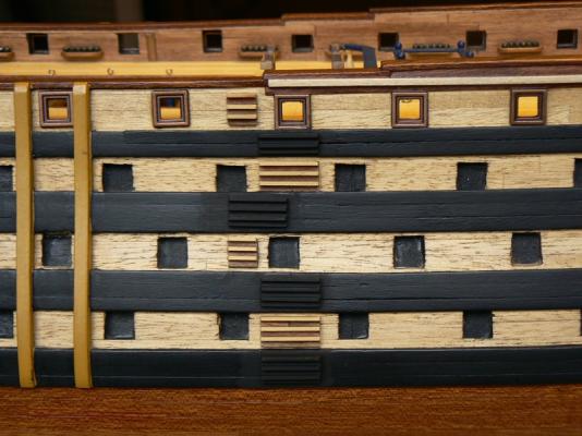
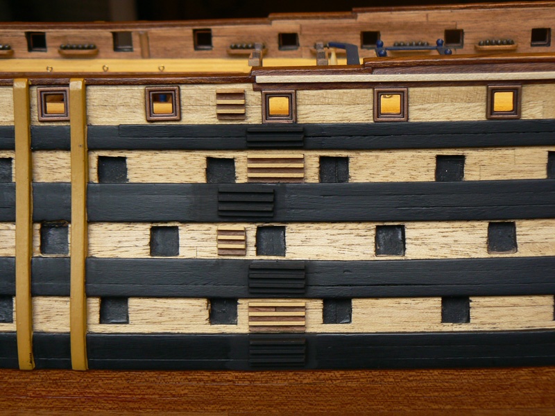
 Hi Fam, first of all I beg your pardon: I forgot to answer you when you posted your message. The answer is: as you can see on Table II of the Cygne plans by ANCRE, that you own, and also on Table IX the horizontal gunport sills seat parallel to the deck (Tab IX) but also to the external planking (Tab II). The vertical sills instead are perfectly parallel to the frames . . the result is a gunport not square shaped but rhomboidal . . Hi Yves, what you see now is only the first step to hide the wrong nail holes on the deck planking. Unfortunately I need to pospone the other steps because I have still to take an important decision: shall I simulate the nails (or better the woodden caps) on the planks or not ? This is a lot of work and should be done now. This is also a critical decision because if I do this simulation I will have also to do the same externally and so and so. I'm not sure to enter in this escalation. Anyway, if I'll decide to simulate the nails, I'll use the same method used here to hide the wrong holes. The only difference will be in the colour of the paint, most probably darker but not too much. Looking with a magnifying glass this method is very, very realistic . . and fast. To conclude, thanks Fam and Yves for your comments, they are very useful to better discover the secrets of ship modelling. Jack.
 -
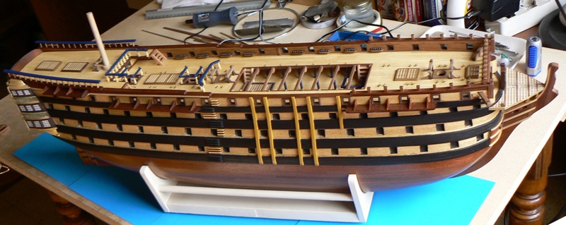
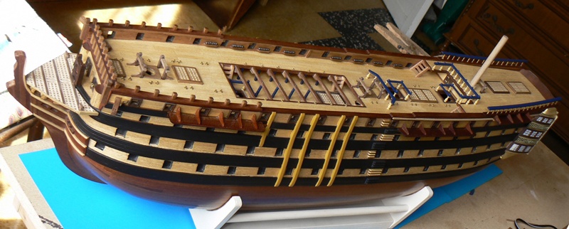
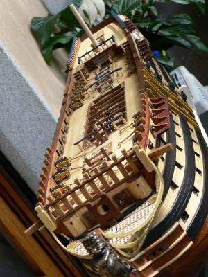
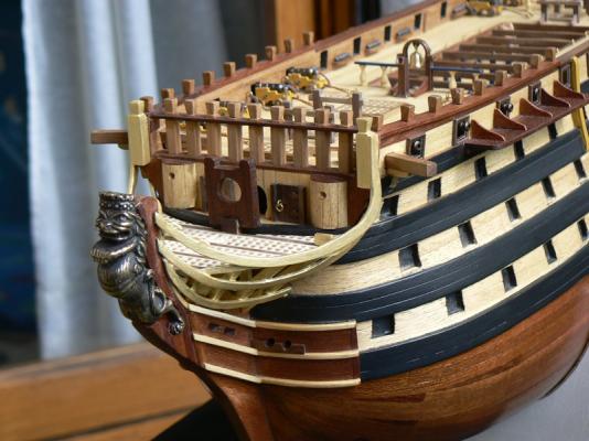
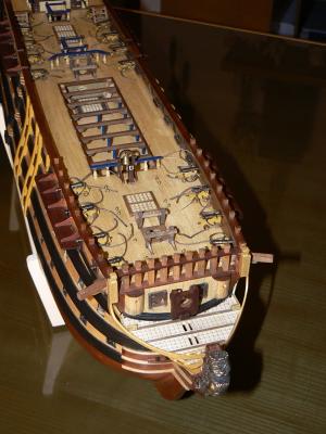
Thursday, February 5, 2015 After a few days of regular activities, finally I came to a point where it is worthwhile to show the progress made so far. Someone might argue that the innovations are not many, and probably is right but he should consider that what I had to do were true finishes, although basic, and these activities take lot of time. Moreover, being concentrated more or less all in the same area, I needed to give the glue time to do his job before moving forward. I begin the usual roundup of photographs starting from some overall views of the hull, then entering into details. As you can see all the inner bulwarks have been completed, even in the bow area where it was a little more complicated. After this activity, which, I repeat, took some time, I worked on the sternpost. Here I first had to sand the two internal central supports to level the inner side. I used the Proxxon BS/E belt sander, very suitable for this type of operation. Then I planked the inside with strips of veneer as I made for the bulwarks. Externally I applied the final shaped piece of the transom that protrudes beyond the hull, to be filled later. It is 1 mm. thick and it's applied over the existing structure and reinforced, on the protruding sides, to take it to the same thickness of the inner part. 01 Brick%20by%20JackAubrey/P1100181_zps54i6obtb.jpg 02 Brick%20by%20JackAubrey/P1100182_zpscgzolmjl.jpg 03 Brick%20by%20JackAubrey/P1100185_zpspllthr5j.jpg In the image below you can clearly see the outside of the poop. A very interesting work was the opening of the two round windows that are nothing more than two gun-ports. 04 Brick%20by%20JackAubrey/P1100186_zpslzuyj8me.jpg Its achievement was a matter of patience and use of appropriate tools. The use of a drill with a big drill bit is to be avoided. I performed +/- twenty holes of 0.8 along the entire circumference of the gun-port and then I cut it all with a coping saw. Obviously the hole had to be finished with files and abrasives. The result can be judged here. 05 Brick%20by%20JackAubrey/P1100183_zpsrvezwgf3.jpg Even at the bow I worked hard, here the basic works can be considered virtually finished, obviously at least in this phase of the build. Aft, the inside wall has some areas to be still completed. But, for the moment, I could leave it as is and proceed with the hull planking. Exposed areas will be mostly covered by a kind of small cabin on each side and in the middle by a kind of box from which the tiller will emerge. Also the hole for the upper part of the rudder is still to be opened, but this will happen later. The few square centimeters that will remain uncovered will be finished properly at the proper time. 06 Brick%20by%20JackAubrey/P1100184_zpskpkuuvll.jpg For the next activity we will discuss in the next post. That's enough for today. Regards, Jack.
-
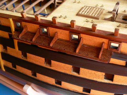
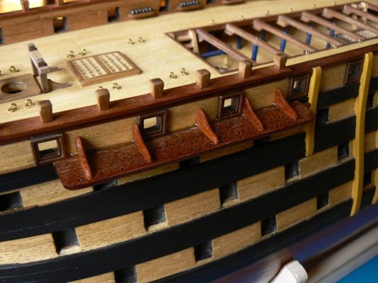
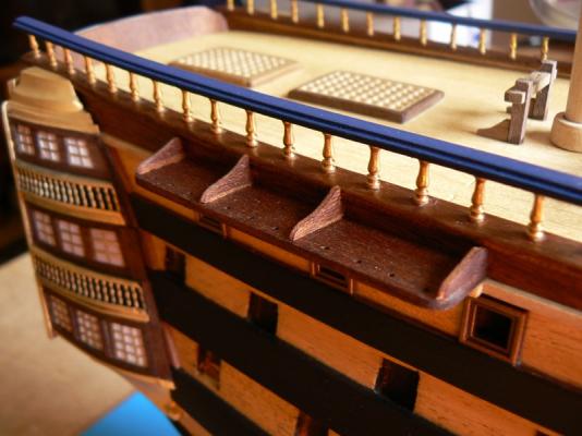
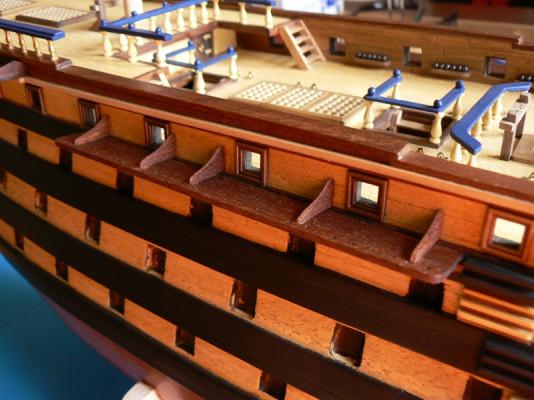
Wednesday, January 28, 2015 In this post I'm showing the right side of the hull, where the work for finishing the bulwarks internally is more advanced, although not so much. Here you should notice the famous strip, described in my previous message, aligned with the lower side of the gun-ports. It is made with walnut 2 x 2. In addition the two vertical sides of the ports are finished with a walnut strip 2 x 1. There is a last strip still missing, theoretically 2 x 1, to install below the 2 x 2. The same work must be done in the bow area, on both sides of the hull. And, again, then I'll have also to work internally at poop. I need to keep myself calm about this last matter, sooner or later I'll arrive at the end. 01 Brick%20by%20JackAubrey/20150128_122038_zps8jksjqw8.jpg 02 Brick%20by%20JackAubrey/20150128_122047_zpsocv0tqbz.jpg 03 Brick%20by%20JackAubrey/20150128_122054_zpsyqimag7z.jpg 04 Brick%20by%20JackAubrey/20150128_114826_zpsdtfwhoec.jpg Regards, Jack.Aubrey.
-
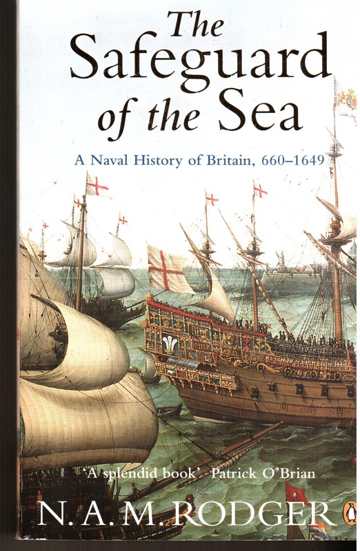
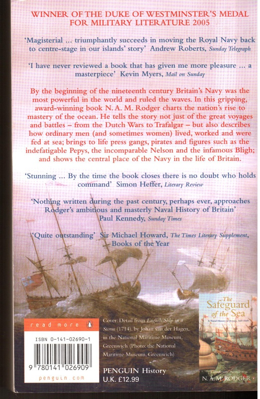
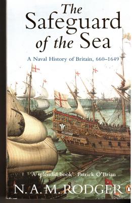
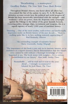
Posted: Fri Apr 18, 2008 When I discovered that "The Command of the Ocean" was only a part of a trilogy it was practically automatic to plan the next book in one of the remaining. So, having terminated the reading of the first I'm now reading the second. To be honest this book should be read before the other but I didn't now that. This is the history of the roman and middle age naval fact of Britain and its content is practically totally unknown in details to a non-specialized reader. Throughout Britain's history, one factor above all others has determined the fate of the nation: its navy. N. A. M. Rodger's definitive account reveals how the political and social progress of Britain has been inextricably intertwined with the strength - and weakness - of its sea power, from the desperate early campaigns against the Vikings to the defeat of the great Spanish Armada. Covering policy, strategy, ships, recruitment and weapons, this is a superb tapestry of nearly 1,000 years of maritime history. No other historian has examined the subject in anything like the detail found here. The result is an outstanding example of narrative history. Does anyone know the title of the third book of this trilogy ?
-
Posted: Fri Apr 18, 2008 In addition to ship modeling, where I normally eat a lot of wood and glue, I'm also a great paper eater. I like very much history (in general) and in these latest times history about the sailship history. I have recently read the book here below depicted and I found it very interesting to understand that particular history (at a relative cheap cost). What follows is taken from a book abstract on the internet. NAM Rodger’s The Command of the Ocean, the second part of his naval history trilogy that began with The Safeguard of the Sea, describes Britain’s rise to naval greatness during the period 1649-1815 when she finally gained sovereignty of the seas around the British Isles. It ably demonstrates the importance of naval history to the life of government and the nation; links naval history with political, social, economic, diplomatic, administrative, medical and religious history and charts the naval histories of Britain’s enemies and neighbors including France, Holland, Spain, Denmark and the United States. Have no doubt, this is a brilliant piece of scholarship, cleverly organized and wonderfully written. Given the promising subject matter of naval warfare to work with it is not surprising that an historian with literary flair can produce a gripping narrative. Perhaps what is surprising is that half the book is devoted to the seemingly mundane background of naval history--how the Navy was managed, financed, directed, and supplied with materials, how the men were fed and so on--rather than the showy foreground, yet it remains a deeply engrossing read throughout. The secret of Rodger’s success is not just down to the cracking narrative and fine scholarship but partly to the way he has organized his material. The main body of the book is arranged into four parallel streams: policy, strategy and naval operations; finance, administration and logistics; social history; and finally the tools of sea-power, ships and weapons. These four themes are broken up into thirty six relatively small chapters each covering a certain time span. Constructing the book in this way has certain practical advantages for the reader. Most importantly, separating the key themes and alternating between them keeps the narrative fresh and interesting while giving the reader the best chance of taking on board the who, what, where, when, how and why of things without losing either the sense of continuity or one’s bearings. Over 100 pages of information are left outside the main body of the text: the front of the book contains several maps, a useful chart listing dates, battles and the names of the ships involved while the back contains an English glossary, a general chronology and appendixes on ships, fleets, rates of pay, Admirals and officials, manpower and naval finance. Rodger’s choice of structure along with his great story-telling abilities means we can assimilate the maximum amount of information with a minimal degree of effort while being thoroughly entertained along the way. On the whole The Command of the Ocean is one those rare specimens that will simultaneously stimulate the specialist and greatly please the general reader. To conclude: a very (for me) interesting book with a lot of informations shown in tables and maps that help very much and can be used as reference when necessary. Jack.


-
Tuesday, January 27, 2015 Let's forget the productivity issue. . . these days I certainly didn't shine. In the few moments that I could devote to this model I started finishing the bulwark internal sides, in order to achieve the main targets on the deck and continue with the hull planking. In this first series of images I show the work in a transitional phase, just to show how much patience, precision and attention this task requires. First I applied a first walnut plank (4mm high and 1mm deep) located right above the waterway. Then, above it, there will be two others strips: one of walnut 2x1 and another of walnut 2x2. At this point the latter should be aligned with the lower side of the gun-ports. Since, however, there is not anywhere the exact height of 4mm, as at some points it's less, and in other it's more, even if only slightly, I preferred to first apply new strips over these two just now described. That's why they are missing ! These new strips are scratch built starting from a sheet of chestnut veneer with thickness 0.4. The planks of veneer are slightly abundant in order to better finish the border when the glue is dried. The photos below show these details while the glue is drying. With a sanding block and a lot of attention, I'll proceed with sanding, task that was already done on the right side of the hull. We will see this part in a next message. Sincerely, Jack. 01 Brick%20by%20JackAubrey/P1100173_zpsi7g9m01a.jpg 02 Brick%20by%20JackAubrey/P1100172_zpsix0gooje.jpg 03 Brick%20by%20JackAubrey/P1100178_zps3yq7vrrm.jpg 04 Brick%20by%20JackAubrey/P1100170_zpsvhkqtvss.jpg 05 Brick%20by%20JackAubrey/P1100179_zpshm7ygj5k.jpg
-
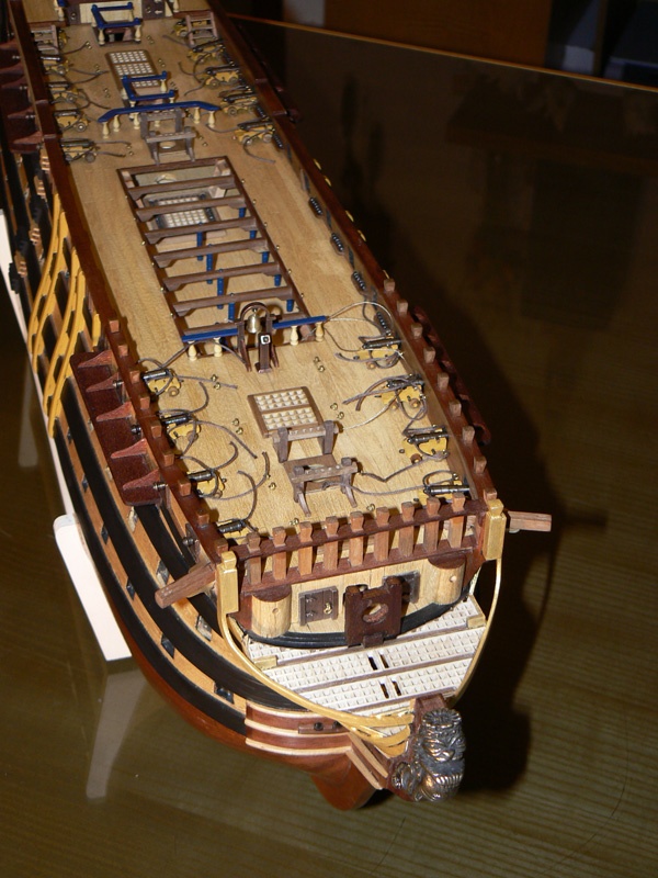
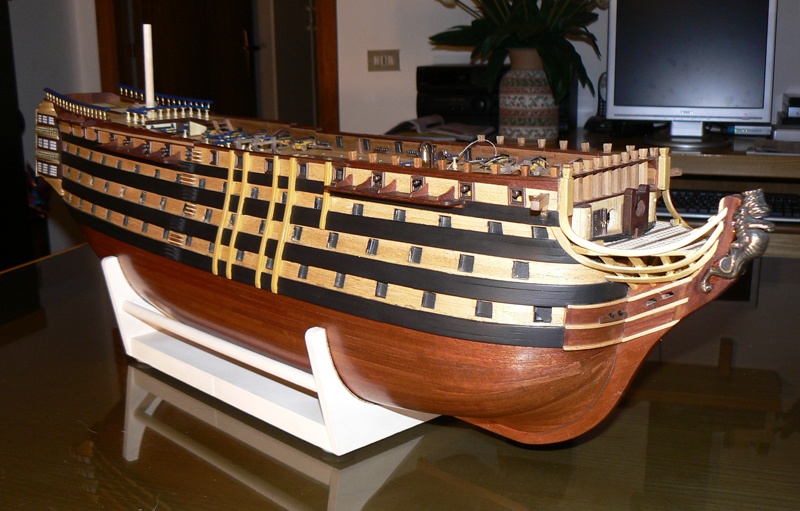
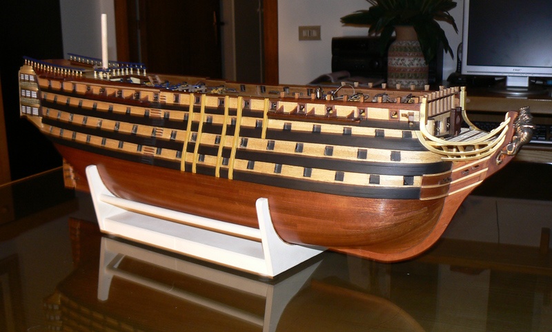
Posted: Fri Apr 18, 2008 I have here the last two photos detailing the forecastle and the head. Regards. Jack.Aubrey


-
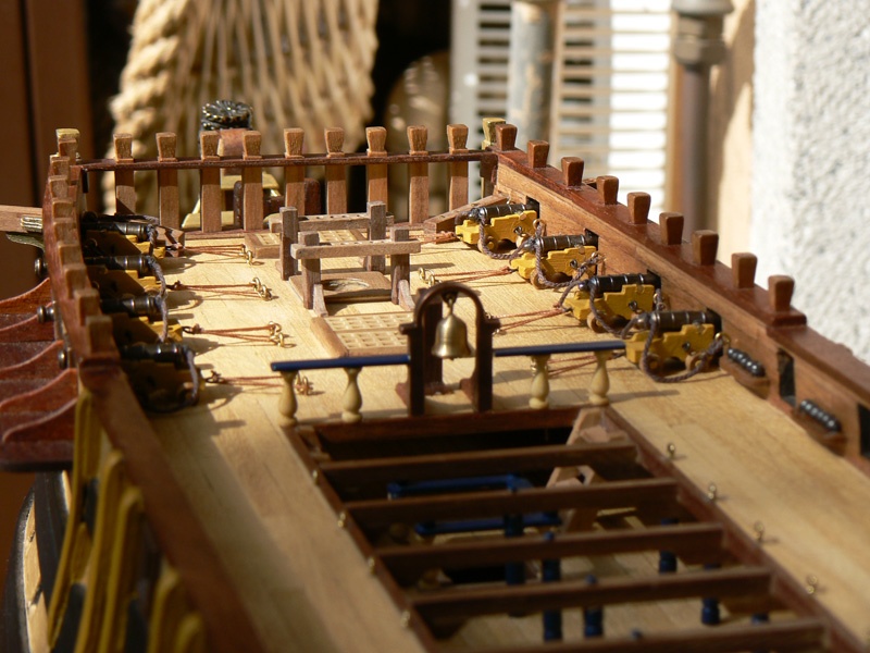
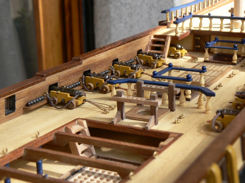
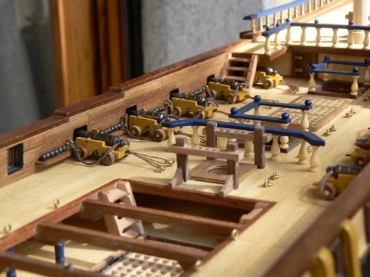
Posted: Thu Apr 17, 2008 The installation of the guns - Quarterdeck These two images show the installation of 10 guns in the quarterdeck. The work is not yet completed in the right side of the images. Same processes and techniques used for the forecastle, nothing more, nothing less, only the guns are different. Regards. Jack.Aubrey
-
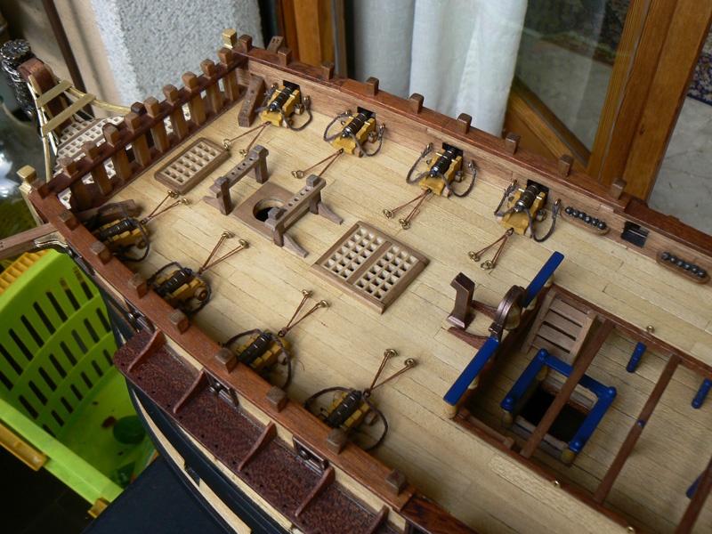
Posted: Wed Apr 16, 2008 The installation of the guns - Forecastle The next three images show the forecastle after the installation of the eight guns. As you can see the breeching tackle is in place and I also have tried to simulate some kind of train tackle. This last particular is not completely 100% a right train tackle because it was for me impossible to find blocks small enough to fit the right scale and I have consequently used only ropes. So, don't shot me for this non conformace to the reality. Anyway I believe it's better this solution than nothing . . To keep in the right place/shape the breeching tackle I have used diluted vinylic glue applied on the rope. Once dry this maintains the given shape. Please note also the bellfry, the bell and the galley chimney. See you soon. Jack.Aubrey


-
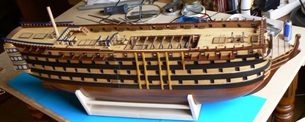
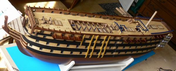
Wednesday, January 14, 2015 Despite the good intentions, I was able to (almost) finish the right side of the hull. In addition, not visible in the photos, because I took them before, I opened four more gunports on the left side. Now only five ports are missing. In the first picture we have a view of the ports all together already smoothed and just only a couple still raw. 01 Brick%20by%20JackAubrey/20150114_095145_zpsb7a6fe96.jpg A detail of the gunports after the sanding process . . 02 Brick%20by%20JackAubrey/20150114_095153_zpsefc85a43.jpg Whereas here there are a few ports still raw, just to understand the sequence of my working activities. 03 Brick%20by%20JackAubrey/20150114_095158_zpse2edfb43.jpg Here the ports are ready to be covered with veneer. . 04 Brick%20by%20JackAubrey/20150114_100459_zps97daac1a.jpg And, here, the veneer is applied, waiting the glue to dry . . 05 Brick%20by%20JackAubrey/20150114_121025_zps520f608c.jpg Next step: the final sanding and completion of all the missing gunports. Finally many thanks to Paul for his comment I greatly appreciated. Cheers, Jack.
-
Wednesday, January 14, 2015 As promised, yesterday afternoon I came back at work and I decided to start with the opening of the gunports for the ship's guns and carronades. The most important job was to mark the position of the 18 gunports on the bulwarks, taking measures using the ANCRE plans. I checked and rechecked the measures several times before considering this activity concluded. Below you can see a side of the model with the locations of the gunports marked. 01 Brick%20by%20JackAubrey/20150113_173955_zps1f0dc4da.jpg The opening of the gunports proved fairly simple and also quite fast. I've run the vertical cuts with the coping saw, being a bit smaller to finish the cut with a suitable sanding block. Regardinmg the horizontal cut, I practiced some holes with the minidrill and then, always with the coping saw, I cut the area not drilled. Then I had to smooth with greater force and attention but at the end the result is very good. You can view the prototype gunport from a couple of different viewpoints in the next two images. 02 Brick%20by%20JackAubrey/20150113_173841_zpsd3cbbb31.jpg 03 Brick%20by%20JackAubrey/20150113_173752_zpsd71cbf25.jpg Then it had to fill the thickness side with veneer, again an activity requiring patience but relatively simple. The important thing is to glue the veneer very well to avoid detachment problems during the subsequent sanding. 04 Brick%20by%20JackAubrey/20150113_180419_zpse8473dd7.jpg Finally, the sanding when the glue was totally dried. This activity was performed using a fine-grained sanding block combined with a very light pressure. The result comments alone. 05 Brick%20by%20JackAubrey/20150113_185119_zps68b3c0e6.jpg Today I'm still at work since this morning and obviously I plan to openi and finish all the gunports of my brick. See you soon. Jack.Aubrey.
-
Tuesday, January 13, 2015 Last Saturday I finished to install the deck planking . . Then I didn't achieved anything else because I had a continuous succession of unexpected events that I couldn't find time for ship modeling. I hope, now, to be able to resume the activities. Before resuming the planking of the hull, I must go to a shipmodels shop to buy other strips of limewood 6 x 2 because, having also used them for the deck, I haven't enough wood for completing the hull. Finally a few words about the process to hide the holes of the nails on the deck, the problem that kept my mind busy for a while: I did some tests on a tablet that I had prepared when I did the test for caulking, doing similar holes and applying the same oil used for the deck, recreating the same starting point. I managed to make them disappear almost completely, even if the process consists of several steps before considering it finished. On the deck of the model I did the first two steps, which already have acheived a certain effect, but for the other steps it would be preferable to wait until the works on the inner sides of the bulwarks are concluded. So I decided that the next step will be to open the gunports for guns and carronades, nine on each side. Probably today I hope to track all them in the right location with precision and to open at least one gunport . . we will see. A cordial greeting to all of you, Jack.Aubrey. 01 Brick%20by%20JackAubrey/20150112_110720_zps53a7cf77.jpg 02 Brick%20by%20JackAubrey/20150112_110457_zpsd5fc6a7e.jpg 03 Brick%20by%20JackAubrey/20150112_110446_zpsf1e8eaa9.jpg 04 Brick%20by%20JackAubrey/20150112_110452_zps2045ade9.jpg 05 Brick%20by%20JackAubrey/20150112_110429_zps57c78d80.jpg
-
Posted: Wed Apr 16, 2008 Two old images I did not publish before . . .
-
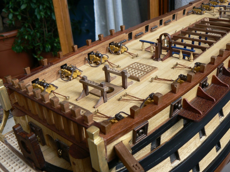
Posted: Tue Apr 15, 2008 The installation of the guns Once terminated the work around the head described in my last messages I started the final installation of 18 guns. The image here attached shows the work in progress . . I have installed two different kind of guns: 10 in the quarterdeck 8 in the forecastle (smaller) I have not yet installed the 10 obuseros (or obusiers) in the waist area simply because I still need to build them . . I have fixed the guns to the deck with four very, very small drops of epoxy glue. Before I installed near to each gun two ringbolts where to connect the breeching tackle. The image below shows the tackle not yet fixed to the ringbolts. The deck begins to become crowded !!
-
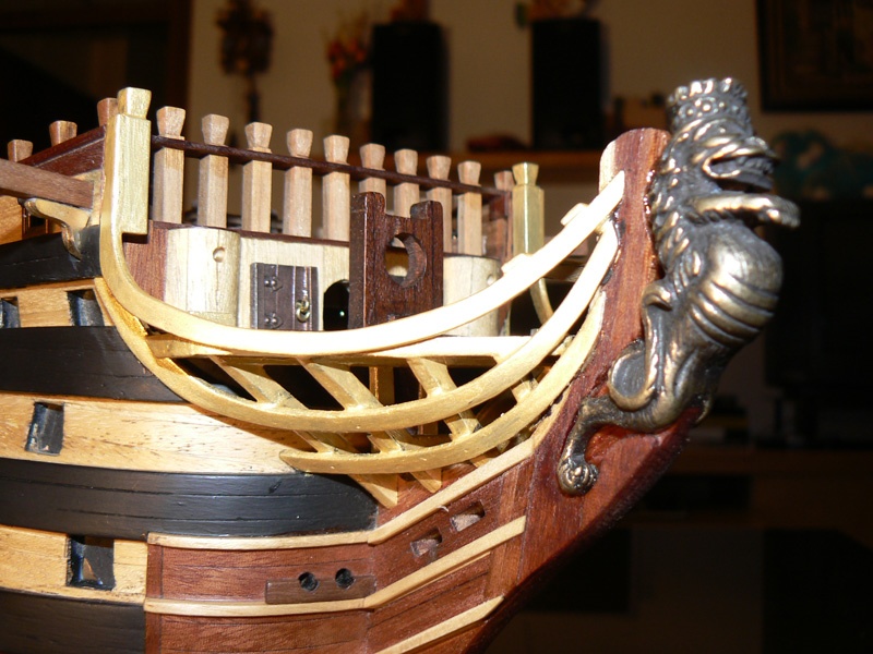
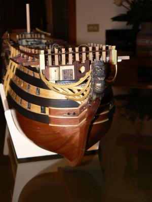
Posted: Mon Apr 14, 2008 The Figurehead: the images that I'm here showing you are details of the Santìsima Trinidad's figurehead. The installation process: in theory the installation of the figurehead is very, very easy. You have only to 1) select the right glue and to 2) glue it in place. But for me this task wasn't so easy. Here is the reason: after the installation of stempost and knee of the head I accidentally broke it. This happened some months ago and I had to repair the broken pieces by re-glueing them and to apply some reinforcements to be sure the same accident cannot occur again in the future. The result was an increase in thickness of these pieces: the original thickness was 6 mm. and the resulting new was close to 8 mm. This made for me impossible to insert the legs of the figurehead in the proper place. So I had to work on the seat of the figure in order to make possible the installation. I had to properly carve the wood in that area until the figurehead finally fit in place. After that the work was easy. See you soon. Jack.Aubrey
-
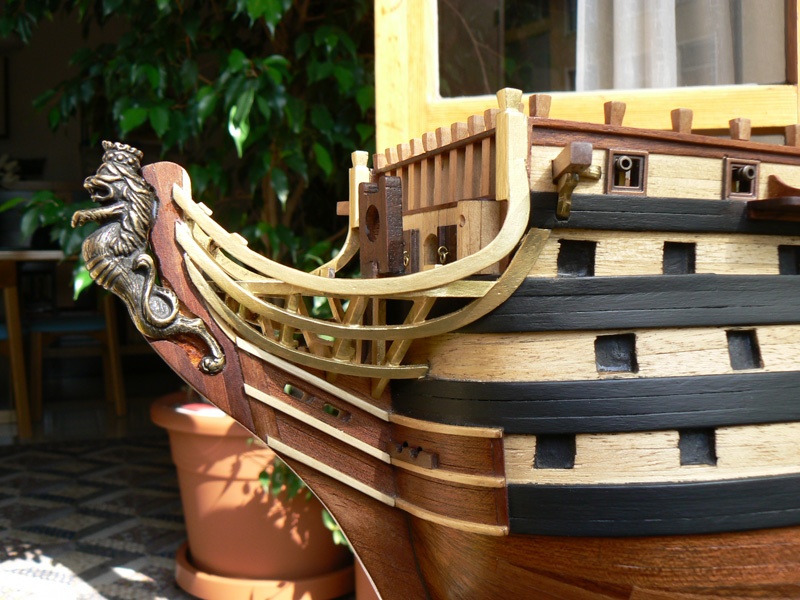
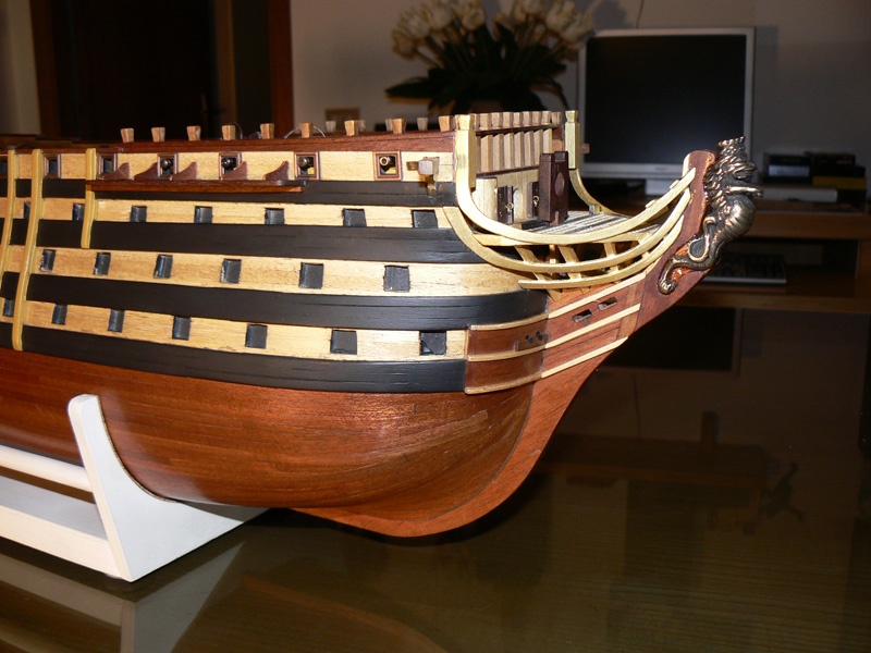
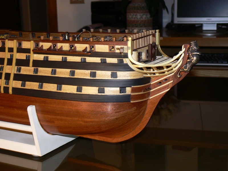
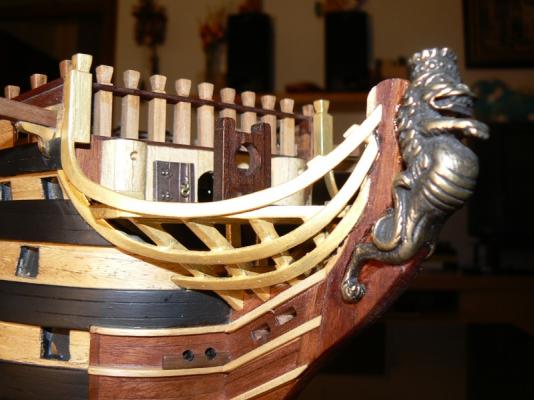
Posted: Sat Apr 12, 2008 Here are two detailed images of the head. The main improvements vs 15 days ago are: 1) the installation of the figurehead, this task will be explained in a future message, 2) the installation of the three rails (main rail, middle rail and lower rail). I made a lot of thinking on how to install these rails because it wasn't an easy task. At the end I decided to use the epoxy glue (two components to mix together before their usage) because I consider it the most powerful glue for this kind of situation and I had to temporarily fix the rails to their beams with very thick steel nails, later removed. I took a total of two days to install all the rails but the result is very satisfactory. When the glue was dry, I made the necessary cleaning tasks and I have applied a first coat of polyuretanic black paint as primer. Then, to follow, two coats of golden poly paint.


-
Posted: Fri Apr 11, 2008 Here follow two images that anticipate the hard work I have done this last week on the prow area (figurehead, rails, cross timbers). In the next days I will write a more detailed report about the work done. Kind regards, Jack.Aubrey


-
I beg your pardon Gary, but I cannot translate in Italian language the word "trunnels", can you help me ?
-
Hi mtaylor, unfortunately, the deck has been already treated with oil. And this untimely process was my mistake, justified by the fear that treating the wood with diluted glue before may alter the color during its final treatment with the oil. I think to prepare a filler using dust of the same wood used for the strips, that I've carefully collected, and mixing this powder with glue or with woodfiller paint. I do not know how it will work so I need to do some tests on samples. Anyway thanks for your advice. Cheers and, of course, happy 2015. Jack.
-
Hello to everybody . . regarding the brick name I'm still in high waters, while I'm considering HMS Colibri . . but there is no hurry, I can wait until I'll have to build the figurehead. The pins holes, instead, are the real problem now: while very small they are visible and this obviously isn't good. I have to do some tests to see what is the best way to make them disappear. Many areas of the deck will be covered, but others will remain open and here it's mandatory to do something. It's a problems to solve before the name, but I think to have time to find a good solution: when the last four deck strakes will be added I can continue my work by finishing the hull planking while in parallel I can find the best solution. Finishing the hull planking means probably some weeks. Waiting is a usual strategy I adopt when I find difficulties and helps to control emotional situations: the time generally resolves most of the problems. If I could come back in the past with a time machine I'll probably use a different way to hold the planks while glueing them . . power of experience ! Finally, based on how the story will be concluded, in theory, there would also to start the tree nailing of all the deck strakes. Honestly I don't know how feasible this last task will be. Looking at the plans each strake has two tree nails every 30/40mm. It's an incredible work and, at prow and poop, the strakes are too close and then my work would be exposed to the risk of showing a poorly attractive effect. Another problem to solve in the future if I'll decide for the treenailing . . Ciao a tutti, Jack.Aubrey
-
Friday, January 2, 2015 To begin, I wish a good 2015 to all users of this forum . . Looking at the previous message it appears that I have not done too much on this model . . it's partly true, because during the Christmas period there was not much time to devote to ship modelling but, anyway, I found two/three days free and I continued with the installation of the deck planks. It is not an easy task and it requires a lot of time !!!! Now "only" two full strakes per side are missing and then the deck "should" be done. But I think that these two strakes are probably the most difficult to install, because they have to be absolutely precise to perfectly close the deck. And after it remains a final detail to be solved: all the countless dots where the thin brass nails, to hold the planks until the glue was dryed, were hammered. The nails were subsequently removed but the small hole remains . . The oil for wood highlights the visibility of these holes and an action is required to hide them, also because, not knowing beforehand that the oil would have highlighted them so well, the various holes result mainly misplaced. I have kept all the limewood dust I produced during the tapering of the strips; mixed with "something" (I have not yet decided whether using glue or woodfiller varnish or clear acrylic paint) I would like to use it to fill the holes with a spatula for painters . . should work ? Will see. A cordial greeting, Jack. 01 Brick%20by%20JackAubrey/P1100166_zps71ee075f.jpg 02 Brick%20by%20JackAubrey/P1100165_zps0cf09207.jpg 03 Brick%20by%20JackAubrey/P1100164_zpsa070ba2a.jpg 04 Brick%20by%20JackAubrey/P1100169_zpsdbda1599.jpg 05 Brick%20by%20JackAubrey/P1100167_zps844bd66e.jpg 06 Brick%20by%20JackAubrey/P1100168_zps9e327db5.jpg
-
Posted: Sat Mar 22, 2008 Building the foremast channels Wednesday I started the building of the foremast channels. Fore channel: the overall length of this channel is 105mm. and it is built with the same mahogany wood used for the other channels. The building process is totally equal to the one of the main and mizzen mast channels; here I have used six pivots to strengthen the installation. The first image represents the starboard side fore channel, while the larboard side channel is shown in the second image. At the time I shot the images I had just finished to apply the danish oil, so the channels seem gloss. This is due to the fact that the oil was not yet absorbed by the wood. Today, after some days, the oil is totally dry and the appearance of the structure is the same of the others.
-
Posted: Fri Mar 21, 2008 Building the mizzen channels Tuesday I started to build also the mizzen mast channels. Mizzen channel: it's the smaller of the three kind of channels. The overall length is 75mm. and it is built with the same mahogany wood of the others. The building process is exactly the same of the main mast channels; the only difference is that now I have used only four pivots due to the smaller length. The first image represents the starboard side mizzen channel, while the larboard side channel is shown in the second image.

-
Posted: Fri Mar 21, 2008 Building the main mast channels Last monday I started to build the mast channels (I have found they are also known as chain-wales; is it right ?). First I started with the two main mast channels, then the mizzen channels and last the fore channels. Main mast channel: it's the bigger of the three kind of channels. The overall length is 135mm. and it is built starting from a piece of mahogany with a thickness of 2mm. The wood supplied for this task was very good and it was enough to me, for achieving a good refinement, to clean it with sanding paper of different grains. I followed the kit manufacturer instructions: I had to drill several holes for the chain deadeye/shroud chain places at the proper distance and position. The diameter of the hole(s) was of 1mm. But my main problem was the fear that the glue on the thickness of the wood was not strong enough to support the future manipulations so I decided to: - make 7 holes (0,75mm. diameter) in the thickness of the channel where - I have glued, with the cyan-acrylate, some brass pivots of the same diameter, leaving them prominent 4-5 mm; - I have then made the opposite holes in the side walls; - I have removed the paint from the surface to glue to provide the best support to glue; - I have installed the channel with vinylic glue and - a bit of cyan only near the pivots and - I let time to all to dry. Then I have applied the channel support brackets in the proper position and I performed the usual tasks to clean the piece from the glue excess. To complete the work, a coat of danish oil. I decided to use the danish oil instead of paint because it allows in the future to use without risks both vinyl and cyan glue. This work was done last monday; two days later the oil was totally absorbed by the wood and now it is totally matt and smooth like paint. The color of the mahogany wood, from the other side is greatly highlighted. The first image represents the starboard side main channel, while the larboard side channel is shown in the second image.

-
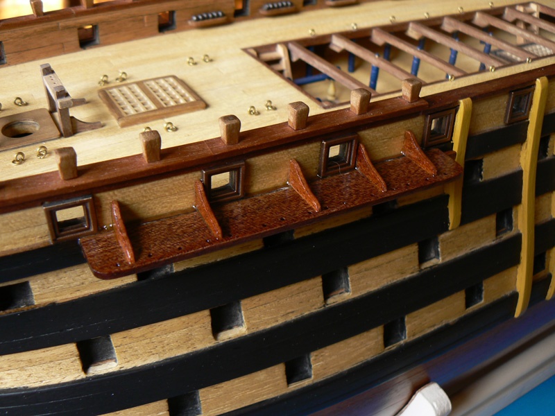
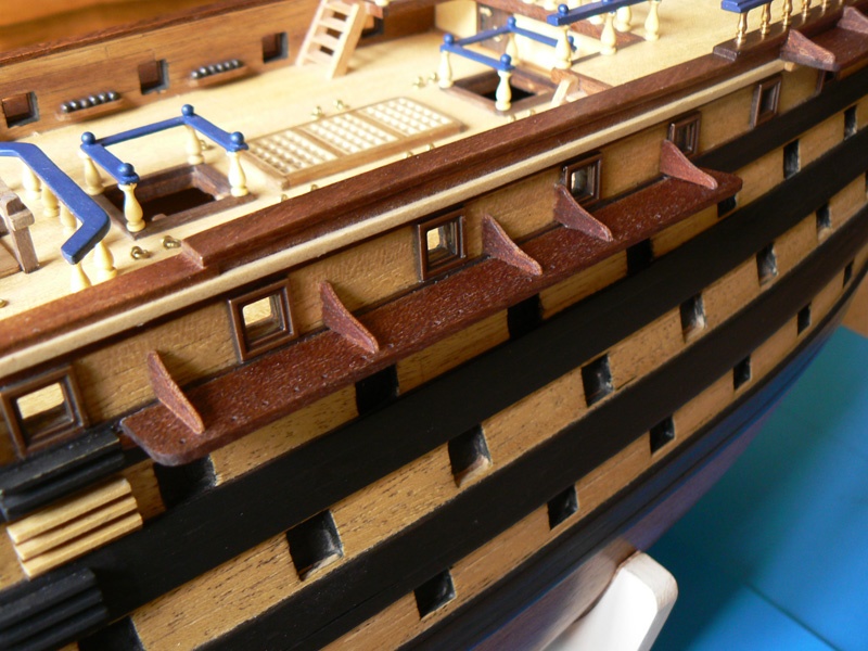
Posted: Tue Mar 04, 2008 A closer view of the side steps that I painted with black . . . To the next issue. Kind regards. Jack.Aubrey