HOLIDAY DONATION DRIVE - SUPPORT MSW - DO YOUR PART TO KEEP THIS GREAT FORUM GOING! (Only 13 donations so far - C'mon guys!)
×


jack.aubrey
-
Posts
1,268 -
Joined
-
Last visited
Content Type
Profiles
Forums
Gallery
Events
Everything posted by jack.aubrey
-
 Tuesday, November 24, 2015 The second round of planking is over (the smallest boat in the two photos). Now it remains the third and last one that will be done using Tanganyika veneer. At the end the wood color will be like the larger longboat visible in the same two pictures. This second boat, apart from the quite different hull form, seems becoming better. Here the project I prepared with a CAD software was better, apart from the last bulkhead (the sternpost) totally wrong and that I corrected during the application of the two layers of planking. 01 Brick%20by%20JackAubrey/P1100385_zpsdksmcykx.jpg 02 Brick%20by%20JackAubrey/P1100386_zpspwnnkitc.jpg Cheers, Jack.Aubrey.
 -
Sunday November 22nd, 2015 Second planking in progress . . 01 Brick%20by%20JackAubrey/20151122_181609_zpsi5izzfdy.jpg
-
Thursday, November 19, 2015 This time I don't have anything better to show that these three (awful) photos of the second shipboat, where I just finished to apply the first layer of planking. At the last minute I decided to stop working on the first shipboat and drive the same experience of the three plank layers also for the second one. This because I feel very "hot" to continue carrying out this type of work and I realized that I'm getting pretty good. So, although more tedious, I prefer to finish the outside of all the three boats before removing them from their building slip and continue with the interior. On this second boat I already started to apply the second planking: but this time, instead of using veneer I wanted to try using birch plywood 0.4mm. The same thickness of the veneer, but theoretically more robust and flexible. We'll see. . Salutoni, Jack.Aubrey 01 Brick%20by%20JackAubrey/20151119_165553_zpslcc3gesq.jpg 02 Brick%20by%20JackAubrey/20151119_165529_zpsj6cfd9ki.jpg 03 Brick%20by%20JackAubrey/20151119_165519_zpsxagugbyi.jpg
-
Hi Don, Andrea and Yves, thanks for your comments . . More in detail, Don, I hope that my previuos message gave you a satisfactory answer to your question about the planks. Andrea, I have to thank you about my choice: after having seen your knarr I had the possibility to know and discuss with Dusek. I think this kind of kit is one of the best challenges to continue modelling far from home without need for lot of equipments and so on, Yves, I think that ship modeling should be essentially a way to spend free time amusing and to achieve this goal there are several paths. I do not consider a scratch build modeller better than a kit o partworks modeller. I know there are many people that thinks the opposite and are ready to start something like a holy war in name of this certainty. But this is not the case for me . . and anyway you can always correct the wrong things ofter existing in kits . . use them as a starting point not as a final target. My approach is basically practical: if I can find something suitable for my needs ready on the market I don't see the need to not use it . . Thanks again, see you soon. Jack.
- 170 replies
-
- 5
-

-
- gokstad
- dusek ship kits
- (and 1 more)
-
Thursday, November 12th, 2015 Yesterday I finished to apply the third and final layer of planking of the longboat. The work was done during four sessions of about an hour and a half, without urgency, applying roughly four strakes per side every time and later consolidating the activity done. As glue I used cyanoacrylate in the package with the brush, very practical for this kind of work; to consolidate, after a smoothing of the courses applied, I used a couple of coats of PVA diluted in water to approximately 50%. A trick to hide the grooves between a strip and the other was to sand with fine grain sandpaper, making sure that the wood powder fills the grooves. At this point, instead of removing the wood powder produced, I immediately past a coat of PVA which in practice pasted the dust remained into the cracks. By repeating the process a few times you get a more than satisfactory result. To dry more quickly the diluted glue applied, I used a normal "hair-dryer"; so I hadn't dead time between one step and the next. Here are some pictures of the longboat . . Now I have to decide whether to keep the current keel, which I think became rather low after three layers of strips or apply it again after having sanded and reduced the current one. Once this will be done, then it will be possible to detach the hull and work inside it. 01 Brick%20by%20JackAubrey/P1100372_zpsko2cbgmj.jpg 02 Brick%20by%20JackAubrey/P1100373_zps94afbo6z.jpg 03 Brick%20by%20JackAubrey/P1100374_zpsrwmflras.jpg 04 Brick%20by%20JackAubrey/P1100371_zpsq065vtzp.jpg 05 Brick%20by%20JackAubrey/P1100370_zpsndxsnriz.jpg Cheers, Jack.
-
Let's see the content of the kit item per item . . in the box we find some pre laser cut plywood boards wrapped in a plastic wrap to protect them from "accidents" . . 01 P1100350.jpg Keel, frames or bulkheads, and a base for the pedestal . . 02 P1100356r.jpg Deck, various rods, probably to be used in building the tree and the several oars . . and, in the upper left, some smaller pieces, some of them made with metal, packed in plastic envelops. . 03 P1100353r.jpg The strakes . . as you can see they are not straight strips, but pre-cut pieces rather crooked . . meaning a design with a 3D CAD software. . 04 P1100354.jpg Other strakes, the round shields, that characterized these boats, and fine wood fittings for the deck . . 05 P1100355.jpg That's all for now, the kit presentation ends here . . . Now all what remains to do is to start building . . but you will have to wait for it until I'll come back in Tuscany (planned for mid December), here I work only on the "Brick de guerre de 24". Sincerely, Jack.Aubrey.
- 170 replies
-
- 7
-
-
- gokstad
- dusek ship kits
- (and 1 more)
-
And now let we open the box to start discovering its content . . At first the model plans in 1:35 scale: this is a single sheet. This fact is not surprising as a viking ship is not a three decker, but something much more simple. In the same photo the paper version of the assembly instructions. 01 P1100351.jpg. Unfortunately (but it is not my case) for non english mothertongue, the instructions are written in English, but the online version are also in Czech, French and Spanish. At a shallow reading it seems clear and quite simple; if there are some inaccuracies they are not established at this time; it's probably necessary to start working before finding something wrong. Below some sample scanned pages to be taken as an example. 02 gokstad35-english_1414511927-3.jpg. 03 gokstad35-english_1414511927-4.jpg 04 gokstad35-english_1414511927-5.jpg Finally, the actual content of the kit: laser pre-cut pieces of plywood and veneer of various thicknesses. 05 P1100349.jpg In the next post we will see more in detail these pieces. Sincerely, Jack.Aubrey
- 170 replies
-
- 7
-
-
- gokstad
- dusek ship kits
- (and 1 more)
-
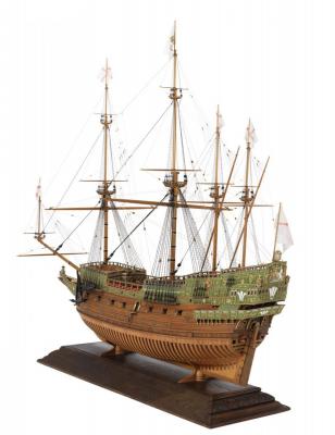
Gokstad Viking Ship, Jack.Aubrey, Dusek Shipkits, 1:35 It seems that for at least one year, but could be even longer, I'll spend two/three months in Cinisello Balsamo (Milan), in the house that I own since more than forty years, and two/three months in Calci (Pisa) in the house of my daughter Silvia where, being currently single, she has plenty of space to guest me and my wife, with mutual synergistic satisfaction. Therefore, by accepting this situation, there is a problem with my shipmodeling activities: in my house I've set up a quite functional workshop, where I am currently building the "Brick de Guerre 24" starting from ANCRE plans; but when I go to my daughter's house what and how can I do? I decided that it's not practical to bring back and forth the Brick and related material: the more the build progresses, the more it becomes cumbersome and the materials and tools needed increase, so I thought a solution that allows me to do any activity in Tuscany without having to make use of the materials and equipments located in my lab at home. The solution is for me the purchase of a kit: with this option I have everything I need (even though that's not completely true) in the kit and then I solve 90% of the problem for the materials while regarding the tools I can duplicate the equipment, on a minimum basis, or take them from home, not having, however, the need for great efforts for transport. Of course, in the months where I'm in Cinisello I'll work on the Brick, and when I'm in Tuscany I'll work on the kit. This means that to finish the models I'll most probably need twice of the time, but I don't think to die in a short time (sign of the horns exposed more and more times) and, with regards of patience, I don't miss it. I took advantage of a fairly advantageous offer from a Czech kit manufacturer, the Dusek Shipkits, http://www.dusekshipkits.com/, and I bought via the internet two Viking ships: 1) the Gokstad ship, found in Norway and 2) the Skuldelev 1, a knarr, transport ship, found along with other boats in Roskilde, Denmark. Both kits are marketed in 1/72 and 1/35 scale. I chose the 1/35 scale. To start I decided to build the Gokstad ship. I want to start with a minimum of history about this ship, on display in a museum located in Oslo. The source is an article I found on wikipedia, from which I extracted some contents relating to this ship: The Gokstad ship is a 9th-century Viking ship found in a burial mound at Gokstad in Sandar, Sandefjord, Vestfold, Norway. It is currently on display at the The Viking Ship Museum in Oslo, Norway. The site where the boat was found, situated on arable land, had long been named Gokstadhaugen or Kongshaugen (from the Old Norse words kóngr meaning king and haugr meaning mound), although the relevance of its name had been discounted as folklore, as other sites in Norway bear similar names. In 1880, sons of the owner of Gokstad farm, having heard of the legends surrounding the site, uncovered the bow of a boat while digging in the still frozen ground. As word of the find got out, Nicolay Nicolaysen, then President of the Society for the Preservation of Ancient Norwegian Monuments, reached the site during February 1880. Having ascertained that the find was indeed that of an ancient artifact, he liaised for the digging to be stopped. Nicolaysen later returned and established that the mound still measured 50 metres by 43 metres, although its height had been diminished down to 5 metres by constant years of ploughing. With his team, he began excavating the mound from the side rather than from the top down, and on the second day of digging found the bow of the ship. The Gokstad ship is clinker-built and constructed largely of oak. The ship was intended for warfare, trade, transportation of people and cargo. The ship is 23.80 metres (78.1 ft) long and 5.10 m (16.7 ft) wide. It is the largest in the Viking Ship Museum in Oslo. The ship was steered by a quarter rudder fastened to a large block of wood attached to the outside of the hull and supported by an extra stout rib. The block is known as the wart, and is fastened by osiers, knotted on the outside passed through both the rudder and wart to be firmly anchored in the ship. There are 16 tapered planks per side. The garboard planks are near vertical where they attach to the keel. The garboard planks are narrow and remain only slightly wider to take the turn of the bilge. The topside planks are progressively wider. Each oak plank is slightly tapered in cross section to allow it to overlap about 30mm the plank above and below in normal clinker (lapstrake) style. Iron rivets are about 180 mm apart where the planks lie straight and about 125 mm apart where the planks turn. At the bow, all of the planks taper to butt the stem. The stem is carved from a single curved oak log to form the cutwater and has one land for each plank. The inside of the stem is hollowed into a v shape so the inside of the rivets can be reached during construction or repair. Each of the crossbeams has a ledge cut about 25 mm wide and deep to take a removable section of decking. Sea chests were placed on top of the decking to use when rowing. Most likely on longer voyages sea chests were secured below decks to act as ballast when sailing. The centre section of the keel has little rocker and together with flat midships transverse section the hull shape is suited to medium to flat water sailing. When sailing downwind in strong winds and waves, directional control would be poor, so it is likely that some reefing system was used to reduce sail area. In such conditions the ship would take water aboard at an alarming rate if sailed at high speed. The ship was built to carry 32 oarsmen, and the oar holes could be hatched down when the ship was under sail. It utilized a square sail of approximately 110 square metres (1,200 sq ft), which, it is estimated, could propel the ship to over 12 knots (22 km/h; 14 mph). The mast could be raised and lowered. While the ship was traveling in shallow water, the rudder could be raised very quickly by undoing the fastening. Dendrochronological dating suggests that the ship was built of timber that was felled around 890 AD. This period is the height of Norse expansion in Dublin, Ireland and York, England. The Gokstad ship was commissioned at the end of the 9th century during the reign of King Harald Fairhair. The ship could carry a crew of 40 men but could carry a maximum of 70. The ship's design has been demonstrated to be very seaworthy. Both kits have the same price: in total I spent € 230, including VAT and shipment. A price (115€ each) quite interesting also if the kits are rather simple. The completed model should look like in the images 01 and 02 here below. Length: 610mm, Width: 260mm, Height: 370mm 01 gokstad35-2.jpg 02 gokstad35-1.jpg The kit of this model, shown in the photos 03 and 04, looks like this: 03 P1100347r.jpg 04 P1100348.jpg Inside there is the materials, drawings and building instructions. On the internet there are also downloadable files with the same instructions at: http://www.dusekshipkits.com/viking-gokstad-1-35 That's all for now, but the adventure has just to begin . . Cheers, Jack.Aubrey
- 170 replies
-
- 6
-
-
- gokstad
- dusek ship kits
- (and 1 more)
-
I'm not sure to understand your comment, but I believe you don't take care that I've planned a third layer of planking . . go back to read my previous messages that you have probably missed to read. If my understanding is wrong then I've not clear the meaning of your comment and, it this is the case, I invite you to clarify your meaning. Regards, Jack.
-
Friday, November 6, 2015 Preparatory tasks in view of the last layer of planking. . The transom: here I used tanganyika veneer, I will use the same wood for planking. 01 Brick%20by%20JackAubrey/P1100367r_zps8h6zctbh.jpg an adjustment on the bow with a filler made with sawdust and PVA glue to properly settle the intersection between the keel and the planks in this area, where just one-tenth may be noticeable . . Here the goal is to implement the best background possible. 02 Brick%20by%20JackAubrey/P1100368r_zpsolgnhxy5.jpg I think then to remove (almost) totally certain hollows due to inaccuracies in the bulkheads. 03 Brick%20by%20JackAubrey/P1100369r_zpsygrdljbm.jpg Now I'll take another week, obviously not dedicated, considering my slow productivity, before finishing with the third layer. Regards, Jack. PS: At the end with these pictures and posts I think to write a booklet on how to build small boats with this method, that will be added to the other 1000 mathods to make the same thing.
-
Thursday, November 5, 2015 Exactly one week after the completion of the first planking of the longboat I finished the laying of the second. I remember that a third one is planned. Here I used strips I made from chestnut veneer instead of tanganyka, because the tanganyka veneer is becoming scarce and enough only for the third layer on this boat, while I have plenty of chestnut. So I have to replenish the tanganyka stock when I'll be back in Tuscany. Below are some pictures of the boat with 2nd planking almost complete, it's still missing to trim the stern but it's a matter of minutes. The situation seems much better than October 29th and also the various bumps, and so on, seem to be softened. I believe they almost disappear after the third layer. With this second planking I almost found the best way to proceed: strips of 3 mm more or less tapered at prow and stern. 01 Brick%20by%20JackAubrey/P1100360_zpsbfnsxc13.jpg 02 Brick%20by%20JackAubrey/P1100359r_zps4lccpaiy.jpg 03 Brick%20by%20JackAubrey/P1100358r_zpseakvzoym.jpg 04 Brick%20by%20JackAubrey/P1100362_zps3pyxmubr.jpg 05 Brick%20by%20JackAubrey/P1100365_zpsrlx98qer.jpg Kind regards, Jack.Aubrey.
-
Thursday, October 29, 2011 It's from early August that I don't add anything new in this log. We left while I was leaving to spend some time in Tuscany and I brought with me some material to build the three boats planned for this Brick. But my good intentions didn't produce practical results and, while I was away from home, I did nothing. Now I am back to my house since October 10th and I had first to spend some days to fix my "business" tasks so I can't resume the shipyard immediately. But . . last Sunday, October 25th, I finally started to do something. So I picked up the long boat and I began applying the first planking (veneer with thickness of 0.4mm). I remember you that for these task I use veneer which has one of the two sides with a thin layer of non-woven fabric. This fabric is particularly useful since the material doesn't either splinter or flake off and can be confortably cut with a cutter without causing burrs, especially in presence of plank tapering. The technique I use for planking these small boats is well experienced: in the past I built four boats for my Soleil Royal in the same manner with full satisfaction. Honestly this method is probably more time consuming compared with other approaches, but I prefer it because has several embedded advantages that lead to a satisfactory and very strong final result. 1) First I start applying the first planking with the woodden side of the veneer (the one where there isn't non-woven fabric) facing inward. I use cyanoacrylate glue applied with the supplied brush. After I apply a few coats of diluted PVA interspersed with light sanding to strenghten the whole. 2) Subsequently I repeat the planking with a second layer of the same material, this time with the veneer facing to the right side and at the end the same tasks with glue and sanding. 3) Finally, the third planking as the final step. In this way I have three times the chance to learn the best method to apply the planks and the third time also my empty brain understands the most effective way to operate. The total thickness of the planking slightly exceeds one millimeter, but it is very, very strong. At this point I detach the hull from the building slip to work inside. But here we should be far away in the future from now, probably in mid-November at best. Below I propose some pictures of the long boat, as it appears after the first step of planking. The first day I started badly, the second a little better and the third better than the second. At the end the result is neither bad nor good. Rather I had to recognize that my projects of the three boats, made with my computer, lack of optimal precision, probably inherited from the ANCRE plans. More than a flaw on the plans it's likely due to the small size of the drawing, where a minimal imprecision of few tenths in practice means a nice hump or recess on the hull . . in my case, if they were drawn on a larger scale, using my approach via AutoCAD I would achieve a better drawing. However, I still have two additional planking steps to address the humps and bumps visible in the photos. The original ANCRE drawings: Brick%20de%2024%20Plans/barca_zps285f10a5.jpg Some pictures of the long boat after the first planking: 01 Brick%20by%20JackAubrey/20151028_164402_zpsjal8yjx9.jpg 02 Brick%20by%20JackAubrey/20151028_164413_zps0c9t6vxw.jpg 03 Brick%20by%20JackAubrey/20151028_164419_zpsoxdifirc.jpg 04 Brick%20by%20JackAubrey/20151028_164520_zps9l9fdfmz.jpg 05 Brick%20by%20JackAubrey/20151028_164601_zpsrmyojnfc.jpg 06 Brick%20by%20JackAubrey/20151028_164618_zps6jp1brji.jpg See you soon. Greetings, Jack.Aubrey
-
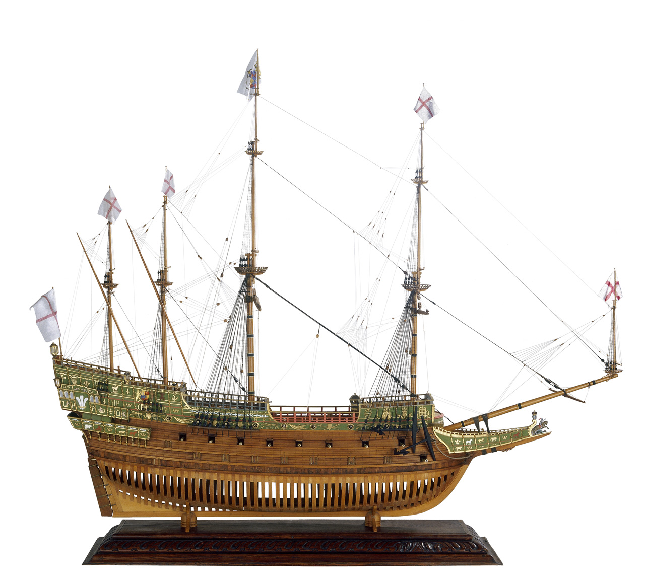
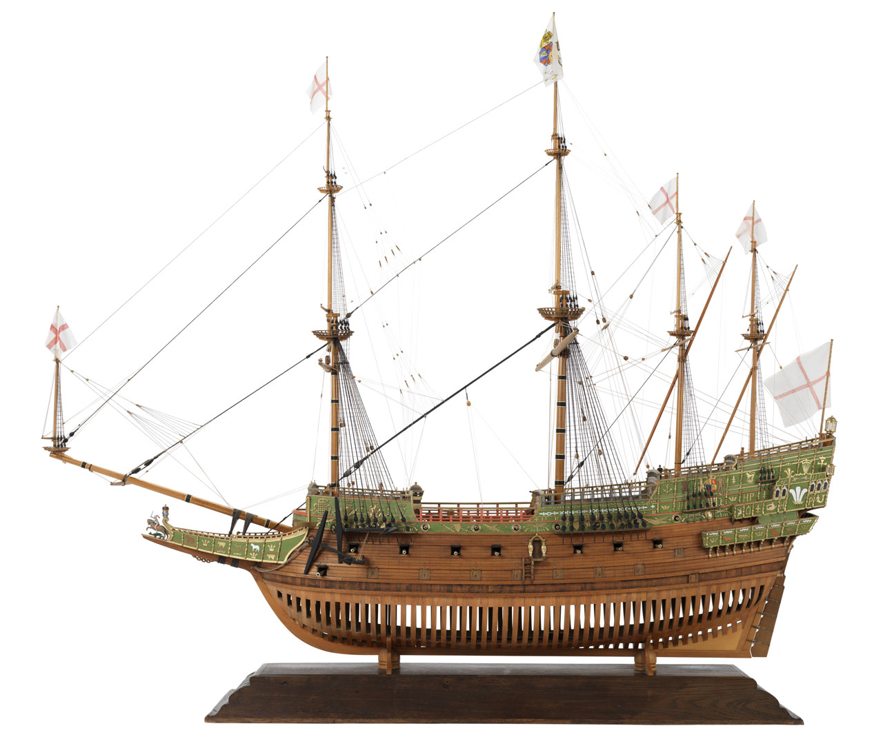
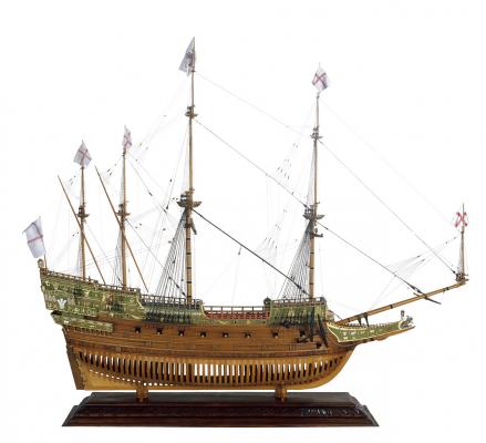
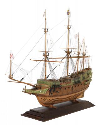
Hi Apollo, don't worry to go off topic in this thread, in this period I've nothing to show, so I like to discuss about ships rather than being idle . . The following four images show the Prince Royal model presented in the book "1st Rate....". It isn't a contemporary model, there is nothing contemporary. This model is of 1991 made by Peter, Basil Grenville in Pinner, Middlesex, UK. Scale: 1:48. It's a full hull model of the 55-gun three-decker ‘Prince Royal’ (circa 1610), built plank on frame in the Navy Board style. The model is equipped, fully rigged with a highly decorated hull, nearly all of which is based on the fine contemporary painting of her by the Dutch artist Adam Willaerts (see BHC0266 and BHC0267). Designed and built by the well-known shipwright Phineas Pett, the ‘Prince Royal’ was floated out of the building dock at Woolwich on 25 September 1610, and had the distinction of being the first three-decker in the Royal Navy. It was common practice during the 17th century for major warships of this size to undergo several repairs during their careers and this ship in its last configuration had a gun deck measuring 160 feet in length and was capable of mounting up to 90 guns in total. It was not until her 40th year, under her Commonwealth name ‘Resolution’ that she saw action engaging successfully at the battles of Kentish Knock, North Foreland and Scheveningen, during the First Anglo-Dutch War (1652–54). During the reign of Charles II, she survived the Battle of Lowestoft in 1665, but during the Four Day’s Battle, 1–4 June 1666, she ran aground and was captured and subsequently burnt by the Dutch. Regarding the German forum, I reviewed it and it's impressive. I have no idea about his sources on the ship but I suggest you to try to communicate with the modeler and get some answers. It seems well introduced . . Regarding SOTS the sources belong after its construction but the majority of them try to refer to her in the first years of her life. There is also a model in the NMM from Robert Seppings, Surveyor of the Navy in the first years of 1800 trying to reproduce it . . in its original shape. Friendliness, Jack.

-
Monday, September 14, 2015 We are now in the middle of September and I stand still so handsome in Tuscany. . shipmodeling is out of my mind, because I had other to think, like you may expect from people on vacation. But not everything went exactly in this way: first I got an interesting opportunity and I rented a garage right in front of my balcony in Tuscany, just across the square. Outside the gate there is a private parking, so I will use the garage not for the car but as a store of what has no place in the house and as "future modeling workshop", if the idea of spending two months in Cinisello Balsamo (Milan) and two months in Tuscany should become a habit. This solution would provide a very convenient environment, with power and water, in order to work on my ship models. There is no heating and sunlight but are things that can be solved. The matter is not as simple as I describe it but it is a first step, even at a relatively low cost: 80 € as monthly rent, all inclusive. Obviously this resulted in more "jobs" involving me and they gave me the opportunity for other actions until today. Now I no longer know what to invent again and then it could be that I finally resume the three ship boats for my Brick and start working on them. . we'll see. If there will be news I'll be back . . friendliness, Jack.Aubrey
-
Hi Apollo, in the book there is an initial section describing the genesis of the first ships of the line, and this section includes the Prince Royal. At the moment I'm far from my house and I cannot review the book contents, so I'm not sure if there are some plans. I'm instead sure there are some canvas reproducing the ship. Anyway my opinion is that should be quite difficult to find seriuos details on this ship because of the lack of proper sources. Also Sovereign of the Seas, much more famous than Prince Royal and built 20 years later, suffers this situation of poor source reliability and the plans, today available at NNM or other sites, date decades later its 1st or 2nd rebuild. You should try to search the NNM to see if plans of the Prince Royal are available, but pay attention to the date of the plans because there were several "Prince ..." in the RN.
-
Friday, August 21st, 2015 Until now nothing new about ship modeling . . I'm now deeply involved with the painting of the terrace railings of my daughter's house . . after suffering some days ago a water flood due to a broken tube while we were outside, luckyly for less than an hour. Result: 2cm. water in all the house rooms in less then half an hour. For the railings I decided for a step by step approach instead of one shot, so every morning I wake up early, at 6:00 and I paint +/- 3 meters of railings, next I prepare other 3 meters for the day after. At 9:00 I've finished and the day starts with a big breakfast and so on !! I hope to finish in a week unless starts to rain . . Stay tuned, Jack.
-
Hi, 10.000 compliments for your outstanding work . . unbelivable and unmatchable. How do you protect your models from dust ? Is your showroom a vacuumcleaned facility ? Sincerely, Jack.Aubrey.
- 883 replies
-
- 6
-
-
- royal caroline
- ship of the line
- (and 1 more)
-
A summer holidays special edition . . Sunday August 9th, 2015 Finally today I was able to leave my homecity and get my long awaited holidays: being myself retired from active work, I plan to stay away not 15 days but approx. 2/2.5 months . . I'll stay very few kilometers from Pisa, in Calci. Calci is a small town but hosts a wonderful national Museum, the "Certosa di Pisa" or better the "Certosa di Calci" built in 13° century. image%201_zpszvilqvq5.jpg In the past it was a big abbey, now it's an Anthropological Museum, where you can find Dinosaur skeletons . . 46824988_zpsfunuw2vz.jpg And a lot of whales skeletons . . calci.jpg_200781171030_calci_zpsuidi05rv.jpg I have taken with me the three launches shown in some previous images and a limited set of materials and tools: I hope to be able to produce something useful during my holidays but I don't consider it as absolutely mandatory. I'll keep you informed of the models work progress. Here below a short(?) intro to Pisa . . Regards, Jack.Aubrey. About Pisa Pisa is world famous for its Leaning Tower and Cathedral (inscribed on the UNESCO World Heritage List) and its many other medieval and Renaissance monuments. It is located in Tuscany, in the central part of the Italian peninsula, on a plain near the coast of the Mediterranean Sea close to the mouth of the river Arno. Its multicultural population totals about 100,000 people, in addition to the many thousands of students who enliven the city. The university buildings are located in the city itself, some in monumental historical buildings and others in new modern constructions. Together the University and the city form a single complex, a “campus in a city”, just as they have for many centuries. Pisa3_zps89tmrfwg.jpg In addition to the University the city hosts two prestigious Superior Schools: the Scuola Normale Superiore and the Scuola Superiore Sant’Anna di Studi Universitari e di Perfezionamento. The latter are centres for advanced studies and research in various disciplines: on the basis of a yearly national competition, they admit the best graduates of the Italian Upper Schools, who study at the University, and have special seminars and activities in the Schools. Pisa is an ideal place for students to live and meet in the city centre’s streets and piazzas, with their bars and pubs, as well as in the classroom. Both the beaches and the mountains are close and easily accessible, as are other famous Tuscan cities, such as Lucca, Florence, Volterra and Siena. The climate in Pisa is generally mild. The city enjoys cool summers and mild winters. There is some rain in autumn and winter although it rarely snows; the summers are dry and make for pleasant excursions to the sea. Pisa1_zpsca0fhu5r.jpg Miracles' Square With extraordinary effectiveness, the phrase «Piazza dei Miracoli» (the Miracle Square), coined by Gabriele D'Annunzio (1863-1938), epitomises the amazement and admiration that for centuries have seized those who, upon passing through the gateway of the circle of walls or emerging sideways from Via S. Maria, embrace in one single glance the pure whiteness of the monuments rising over the lush green of the turf. One is also amazed by the unique isolation of this group of monuments: the large area where the sacred buildings rise is actually on the edges of town, in the north-western corner, looking almost proud and distant from the daily bustle of the town. But a careful historical interpretation and the contribution of some recent archaeological findings give back to the Cathedral all its centrality, based on the original choice of the site and preserved through the centuries as the heart of the religious and civil life of Pisa. In order to fully understand it, one must place oneself in the maritime dimension that since Etruscan times has made the town great, located as it was in a favourable geographical site that placed it at the centre of a network of maritime, river and road routes, with a hinterland that offered a wide range of produce as well as wood and stone for its buildings, thus boosting the settlement of some important manufacturing facilities. The Auser River that no longer exists - used to flow close to the Square, first along the northern edge, then bending south into the Arno River. The Auser, a few hundred metres from here, near today's railway station of Pisa-San Rossore, hosted a river port which worked for one thousand years, from the Etruscan to the late Roman age, and which has come back to light after an extremely long period of oblivion, by the late XX century. It is just by rediscovering this older structure that the location of the Cathedral loses its seeming marginality to take on a new, fuller meaning: in the light of the process of Christianisation of Pisa that according to some recent studies seemed to come from the sea, the site takes an unusual centrality, which is no longer perceivable, if related to the nearby river port facility that kept working through to the V century AD. So, this was the place chosen for the Church of Pisa since its origins, which are unanimously considered to date from before Constantine's peace pact of 313. But the oldest sacred buildings were pulled down with time and the monuments we can admire today date back to the mid-centuries of the Middle Ages, when at the peak of its glory after its triumphs at sea Pisa asserted its supremacy over the region and all over the world, going so far as to claim for itself the role of a 'new Rome'. Such boundless pride and awareness gave birth to the plan to rebuild, near an earlier cathedral that has been rediscovered during recent archaeological excavations, the new church of Saint Mary founded in 1064, the year of the triumph of Pisa against the Saracens in Palermo, whose spoils were partly invested in building the church. The «temple of snow-white marble» this is how it was called by the author of the funereal inscription for its architect, Buschetto represented the whole civil and religious community; and it had to reflect its fame and power to the eyes of the world: epigraphs were placed on the façade to celebrate the main maritime victories; reused pieces of Roman monuments were fitted on the sides to highlight the greatness of Pisa as the 'other Rome'; the façade was richly decorated with ornamental features, such as the outstanding Arab-inspired polychrome lozenges; finally, the rooftop was adorned with the magnificent Islam-made bronze griffon which is now on display at the Museo dell'Opera (the original one has been replaced by a copy), coming perhaps from Spain and most likely arrived in Pisa with the spoils of some military expedition. The Baptistery, founded in 1152 on a design by Diotisalvi, was built in front of the Cathedral, lined up with its façade: a building that according to the latest studies is deeply imbued with the memories of the Holy Sepulchre of Jerusalem, a fact that goes back to the issue of the influences and relations between the architecture of Pisa and the East. The whole town was involved in the construction of the building which had been designed to host the font where the people of Pisa were consecrated Christians: the contemporary chronicler Bernardo Maragone narrates that one of the eight pillars coming from the Isle of Elba and from Sardinia, placed inside the Baptistery in 1163, was lifted and set in its place by the inhabitants of Porta Aurea. The round plan of the Baptistery was taken up again in 1173 by the anonymous designer of the Bell Tower (Bonanno Pisano? or still yet once again magister Diotisalvi? ). A unique work in its roundness which recalls the curves of the nearby apses of the Cathedral, sharing with the other monuments of the Square the recurring motif of the pillars and small arches. Just after its completion the most famous monument in town was affected by that 'mysterious disease', which has made it famous all over the world and at the same time gave it the serious static problems that have been solved after over eight hundred years of trepidation by the strengthening work carried out in the 1990s. With the Bell Tower, the group of monuments of the Cathedral seemed to be complete; but in the thirteenth century, while the works went on and the buildings were enriched with wonderful works of art, two new buildings were added to the site of the Square as it looks today, both born on the decision of the great archbishop of Pisa, Federico Visconti. The New Hospital, was built south, imposed on the township in 1257 by Pope Alexander IV as a token of the reconciliation with the Apostolic See after over fifteen years of a crisis, designed to help pilgrims, the poor and the sick: it is the big building that today hosts the Museo delle Sinopie, where we are now. In front of this building, in 1277, a new cemetery began to be built for grouping the tombs which until then had been left scattered all around the Cathedral. This plan led to the building of the Cemetery, an extraordinary four-sided cloister which with its marble façade closes, on the north side, the «Piazza dei Miracoli» (Miracle Square) which had been conceived for the burial of the dead and instruction of the living, who were asked to ponder on life on earth and the eternal one through the magnificent series of frescos whose preparatory sketches the so called “sinopie” are now kept in this Museum. Pisa2_zpsflyhrvls.jpg
-
Hi Redshirt, first I want to thank you for your message, I like too much to interact with other people about the many paths one can follow to obtain a given result. And for this goal, a forum is a fantastic media to exchange experiences, ideas and so on. Regarding to what you wrote . . "I think you are overdoing it with the photo etching." You are most probably right, but, if viable, this is the best solution in terms of carefulness and precision. As I wrote this is my first experience with copper sheating and, by habit, I tend to evaluate all the possibilities starting from what I think is the better choice (for me) passing then at the second and so on. Don't forget I am in a situation where I can wait and lose some time in searh of this. Obviously the choice will be a kind of compromise between several factors (cost, feasibility, etc) and I will not accept to spend for this task five time the money I spent until now for the whole project . . "Using copper tape and an appropriate stamp should do the trick (as described in the Art of Ship Modelling) at a reasonable price and without any detriment to either realism or aesthetics." I am aware of this method . . I am a little concerned about the usage, or better the building, of the stamp. It may seem a simple tool but I'm not sure it is really simple. In addition, if you read the book you cited from Frolich you should consider that he made the copper sheating twice because the first attempt wasn't satisfactory . . And, encore, I would like to build a model that can live for at least a century, and I'm not sure the self adhesive tape will last so much . . I'm just now arrived to half century with the superglue on a model !! "If you don't have the book i can send you the page where Frölich's approach is described. It's in german but the pictures alone should be sufficient." I thank you for your offer but I have this book, in italian language, and I read it some time ago. So I don't need it. In general I agree with Frolich on many things but for other matters its methods are not for me: I have the impression he wrote his book to show his method, not all the methods to perform a given task. For this reason I find more innovative some easteuropean ship modellers such as Alex Baranov or Mikhail Bezverkhniy. Anyway, thanks again for your participation. Sincerely, Jack.
-
Hi Yves, I agree with you ! It is a very interesting book dedicated to RN 1st rate ships. There is lot of pictures in it and covers the matter from the first ship, the Prince Royal, to the last sailing vessels and the first steam vessels. I have a private library of about 30 of these books: they are quite expensive and are maily written in english language. Italian literature about these topics is poor and difficult to find on the market. In addition I have found on the interet a big number of books in PDF format that increase the written material available. Obviously the paper media is my preferred but the difference in space needed to keep it is a little bigger . . Hi Daniel, thanks for your suggestion about DIY. I remain convinced that, considering the dangerous materials to manage, it may not probably be the proper matter for my skills. Anyway, I'm following your idea to research on the internet to find written material to manage this option. And, as you wrote, there is plenty of sites describing the photo-etching process, also videos. May be that a better knowledge will help me, although I will keep, for the previous considerations, this idea as my theoretical "Plan Z". Obviously a success in such enterprise should be very exciting . . Kind regards, Jack.
-
Tuesday, July 28th, 2015 Here are pictures of the three boats all together, to highlight the differences in size. Now I should start the planking, as also the shaped bow woodblocks are in place. As I anticipated, double-layer planking in Tanganyika veneer, 0.5 mm. Regards, Jack. 01 Brick%20by%20JackAubrey/P1100341_zpsj5nziuqt.jpg 02 Brick%20by%20JackAubrey/P1100342_zpshl2gg24p.jpg 03 Brick%20by%20JackAubrey/P1100343_zpsiirtbdrz.jpg 04 Brick%20by%20JackAubrey/P1100344_zps2lswqmj5.jpg 05 Brick%20by%20JackAubrey/P1100345_zpsti6xppza.jpg 06 Brick%20by%20JackAubrey/P1100346_zpsn73z0vcy.jpg
-
Saturday, July 25th, 2015 During these last days, I finished to cut out the elements of the third boat, the smallest one and whose plans are presented as pictures here below. The task of preparing all these pieces, keel and bulkheads, has been quite challenging as they are really very small pieces, cut from a plywood quite thin and I had to take care of them with a lot of patience and attention to avoid breakage, while still maintaining the necessary precision of the cut. So today I finally was able to assemble all the pieces using the same proven method of the two other boats. Apart few finishing details now the basic material to further proceed on their construction, when I'll go to Tuscany, should be quite ready. As I wrote my departure is delayed some time because of unexpected problems. No peace for us poor pensioners . . for now let me publish the plans of the last boat, images will follow. Friendliness, Jack.Aubrey. 01 Brick%20de%2024%20Plans/ScialuppaPiccolaLato_zpsegjmjqmh.jpg 02 Brick%20de%2024%20Plans/ScialuppaPiccolaChiglia_zps1vd4mgov.jpg 03 Brick%20de%2024%20Plans/ScialuppaPiccolaPoppa_zpsqtfmuhbm.jpg 04 Brick%20de%2024%20Plans/ScialuppaPiccolaPrua_zps61xmhlf4.jpg
-
Thanks Carl, Mark and Andrea for your comments: you confirm my negative impression to be taken for a ride or even ripped off. Before forgetting my idea about the photoetched plates I'll try other possible ways. I have no hurry to get the hull copper sheated so I can spend some other time to search for better luck. I'll resume the matter in September: here in Italy we are now fully in the middle of the summer holidays season and it is now difficult to contact people and/or to get answers. Being this my first attempt to copper sheating a hull I have read plenty of articles, messages, etc about the matter and I hope that if the above solution will not be viable, I'll be always able to setup a "Plan B" o even a "Plan C". In the meantime . . . read the next message. Rgds, Jack.
-
Tuesday, July 21st, 2015 A few days ago I wrote with some enthusiasm, about the photo-etched copper plates, as below: Today, as promised, I received the answer, answer I reproduce in full here below: I am genuinely stunned . . I asked for a quotation of 10 sheets, A4 size, although in reality I would need only 5. This because if the option was interesting, I was able to propose the material also for my friend FAM who is doing the same model. On the website they advertise it was a really easy matter, I had only to prepare and send them an AutoCAD file, done following certain rules, and their highly sophisticated and flexible equipments would be ready to do all the work !! It sounds me like a steal . . the AMATI photoetched plates available on the market, unfortunately too small for my needs, cost about 15€ per sheet !! I think at this point I will have to reconsider other options, not last to leave the hull in natural wood . . and of course try other suppliers. It's a pity for the time lost but with shipmodeling we always need lot of patience ! Anyway I'll resume the matter after I'll get back from Tuscany. By the way I'm facing some other problems and I'll will delay my departure for a couple of weeks. Regards, Jack.
-
Saturday, July 18th, 2015 The second shipboat is well under way . . now there is only to apply and shape two bow wood blocks and then I'll switch to the third one to have all the material ready for my stay in Tuscany. 01 Brick%20by%20JackAubrey/20150718_193928_zpsgqzfcncz.jpg In the next images a comparative view between the two boats. The smaller one will be hosted inside the larger on the ship deck, between the two masts. 02 Brick%20by%20JackAubrey/20150718_193756_zpsjps3rtmr.jpg 03 Brick%20by%20JackAubrey/20150718_193718_zpsej6vu3ze.jpg Cheers, Jack.Aubrey