HOLIDAY DONATION DRIVE - SUPPORT MSW - DO YOUR PART TO KEEP THIS GREAT FORUM GOING! (Only 13 donations so far - C'mon guys!)
×


dewalt57
-
Posts
145 -
Joined
-
Last visited
Content Type
Profiles
Forums
Gallery
Events
Everything posted by dewalt57
-
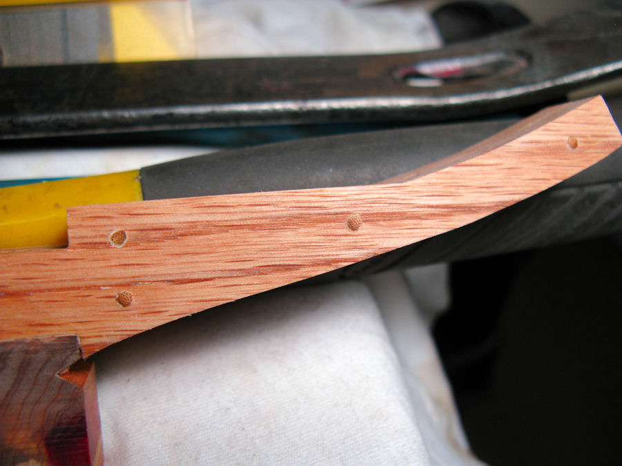
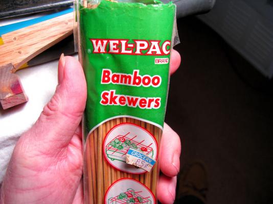
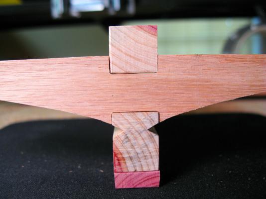
 Testing with Treenailing the formers with bambo skewers. Not sure of their exact placement but this is one idea. Does look kind of cool and adds to the detail. These are approx. .093" in diameter skewers. Also tested a Minwax #235 Cherry stain/sealer on the Oak, looks good to me! AL

-
Pete....... I don't think it will totally eliminate the need for sanding to fair the hull but it seems to give a good point to start from. AL
-
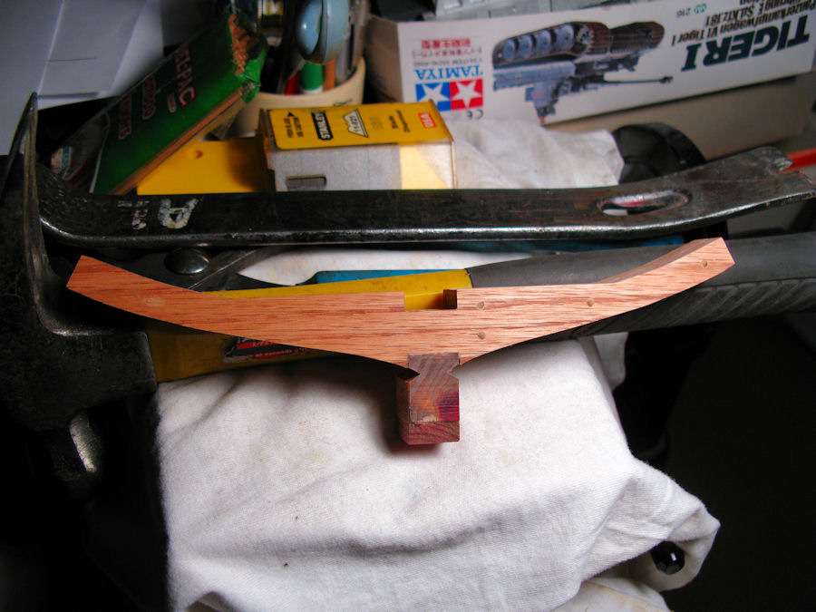
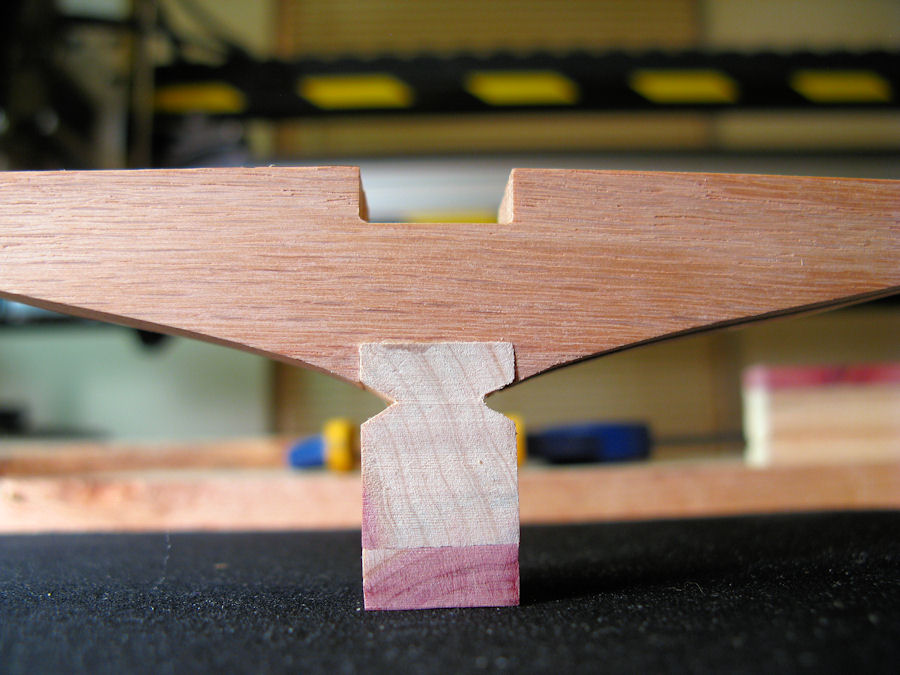
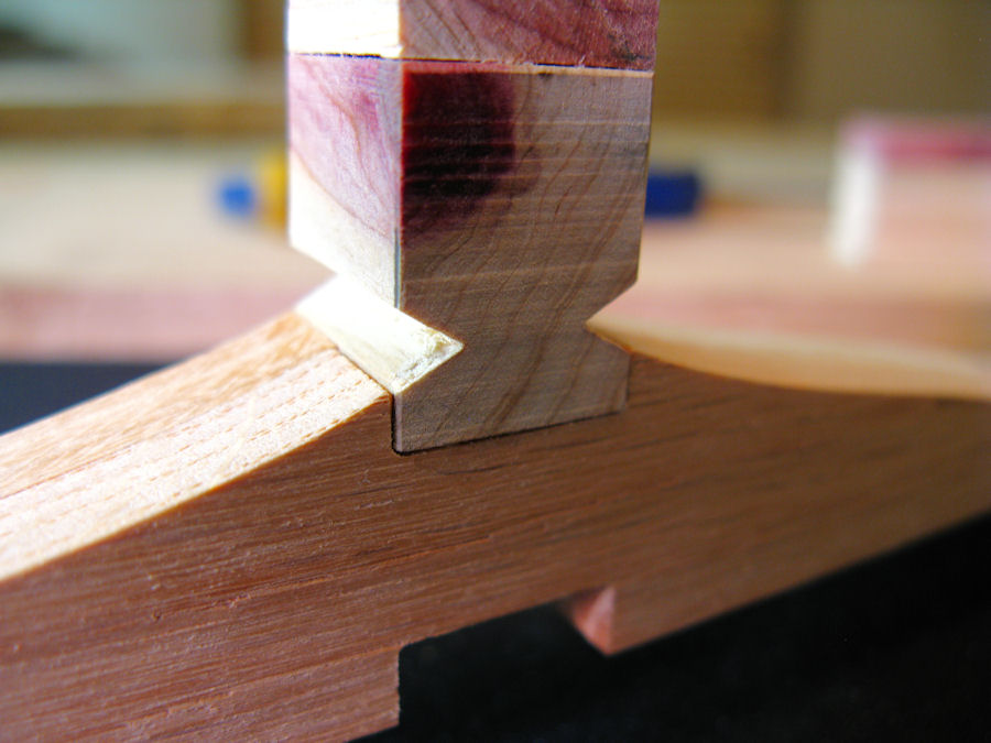
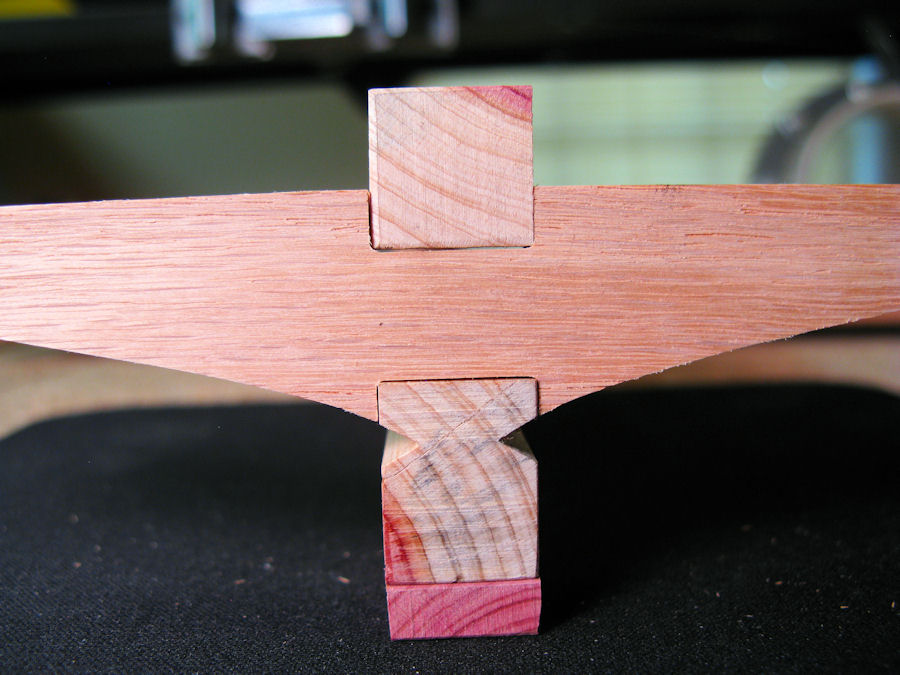
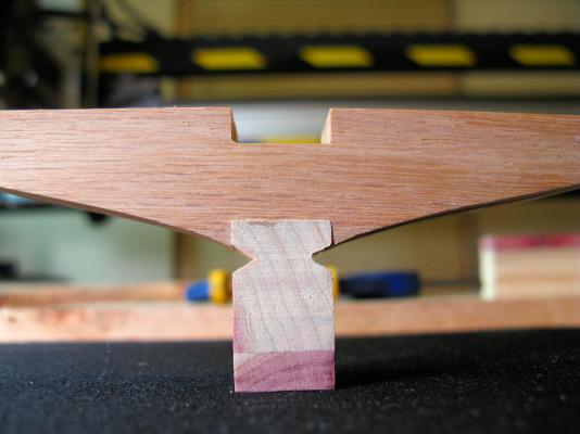
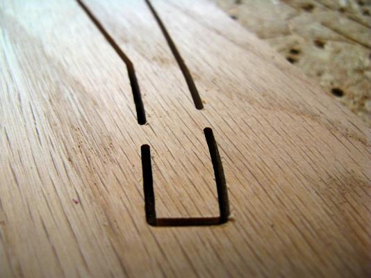
Cut another test former and placed a short section of Keel for a mock-up and check the V-notch location. Looks good to me! AL

-
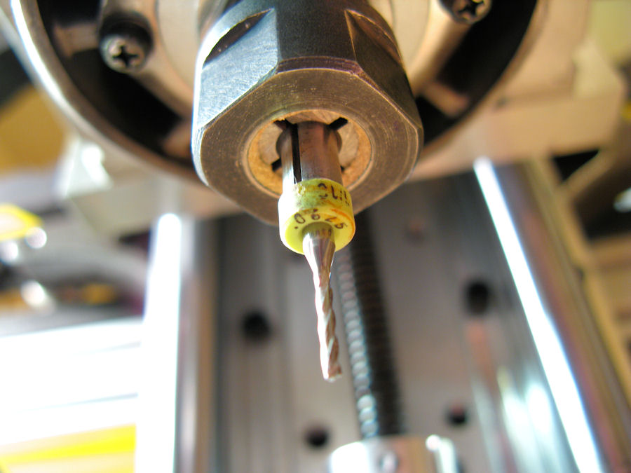
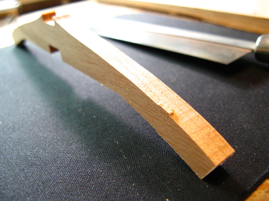
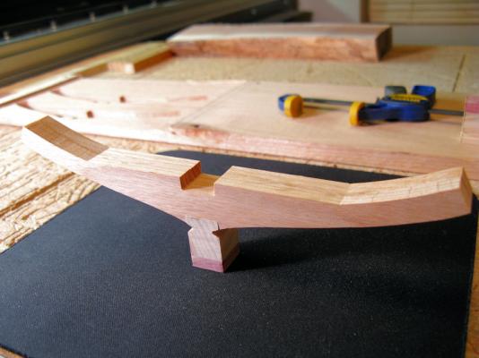
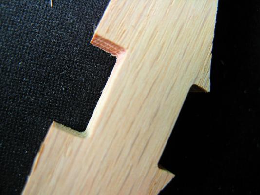
Having not decided on a type of wood and needing to test a new cutting bit, I did a test cut on some Oak I had. Here's the results. Did have some tear outs doing the surfacing to height but could use the side to glue on. The cut out sides had no tear outs and don't look too bad at all with this new bit I'm trying out. I'll be replacing those Cedar Keel parts with Oak soon!! Here's the parameters I used to cut with: 1/16" Micro Bit, type unknown, 4 fluke, depth of cut 3/8" max. Pass depth : .0250" per pass ( 15 passes to complete cut ). Feed Rate: 20 IPM Plunge Rate 20 IPM Ramped cut Tabs: .200" length, .100" Thick. 16 mins total time to finish cut. AL


-
Allen...... yes, there is no easy way to it other then a good hand drawn CAD drawing. Ray..... approx. $5000 over a period of time for a "Build it yourself" machine plus software and a dedicated computer for it. Matrim..... I only wished it would come out like the program shows.... LOL A finished part that needs no sanding....NOT !!!... LOL AL
-
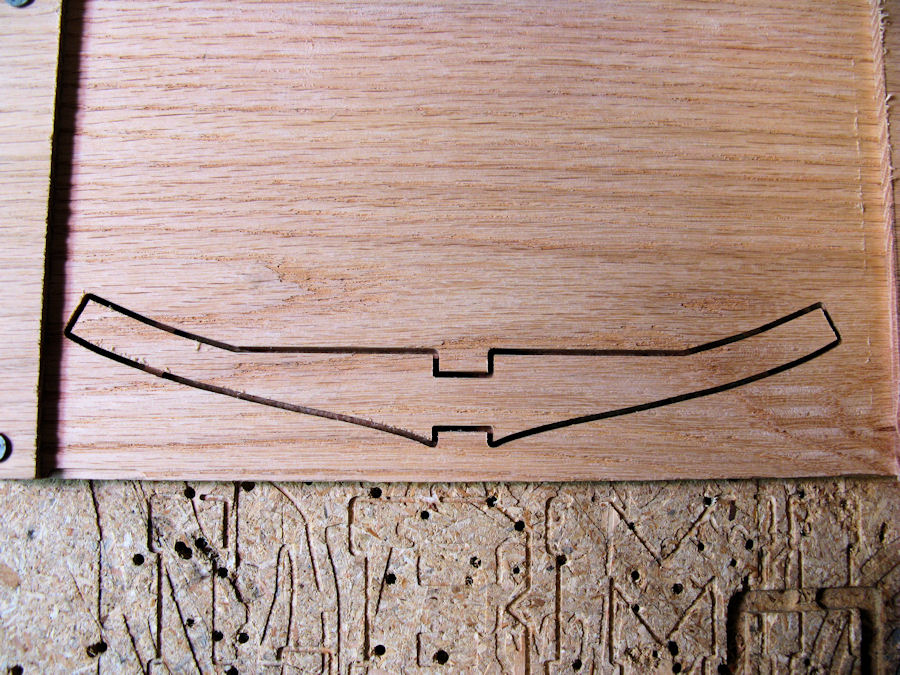
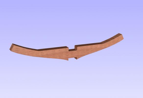
What a finished cut part might look like, according to the gcode software, after the router has its way with the wood...depends on a few factors like bit used, type of wood, air temp, humidity, if your above or below the equator.... etc...LOL AL
-
I agree Allen, its a real pain to do! Basically.... I just draw a new line on top of a captured screen shot of the PDF which is saved as a JPG file, the JPG file is then pulled into my 2D CAD program and placed in the back ground. Then I draw on top of the original lines, getting as close to accurate as I can to the original shape. I have yet to find a good raster to vector converter that doesn't distort the image which still has to be redrawn by hand, so might as well do it by hand to start with and not even deal with any converter program distortions. Slow, yes!!..... its a labor of love for sure !! One aspect of it is that you get very familiar with the object your making! Once the new drawing is made, it is sized to the scale needed for the build and exported as a DXF file for use in my GCODE program which makes the cut file for the wood router to follow to make the part. AL
-
Looking good Ray!!! AL
-
I understand your position, this was not explained in the file stipulations that you had to make a ship a certain way!! Maybe this should be posted for new people to understand before putting the plans out for building! Have a nice day! AL
-
Now just where exactly does it say that on here!!!! I see no such thing implied on the file stipulations. AL
-
The one thing I wish was that all ship drawing files were in DXF format instead of PDF. DXF is a vectored drawing that can be scaled and manipulated in a CAD program very easily where as a PDF file is a raster files and can not be manipulated in a CAD program, it can be imported and drawn on top of, its like redrawing the whole ship again!!!... LOL I haven't found a PDF to CAD program that will reliably convert with out making lines distorted and totally messing up the drawing, in the end I've ended up redrawing over the converted drawing.. LOL Why DXF you may ask? The CNC wood mill software (I use Aspire) wants vectored type drawings to convert to gcode, it will not make gcode out of PDF files and no gcode means no cut file!! So I'll have to redraw all these PDF files of hull formers so I can make gcode cut files in Aspire that can be understood by the router machine driver software (Mach3). Yes, its a lot of work but a labor of love to be sure!! So don't misunderstand me, I feel very fortunate just to get the PDF files for this project!!! If it was easy, everybody would be doing it.... LOL DXF was years ago THE standard file protocol between CAD programs, still is I guess, how PDF got into the game is anybody's guess, I guess because its everywhere you look now, PDF files can be locked files which can not be changed by people, are easily read by millions of people all over the world, can be printed easily, free viewer, etc...etc. In other words the only game in town if your not CAD savvy like some of us are.... LOL So I guess I better get busy with my CAD software and get started doing some drawings..... LOL AL
-
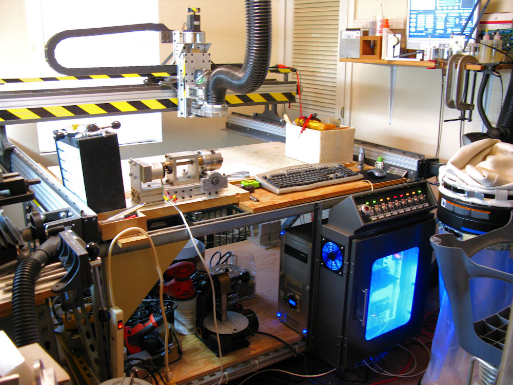
Hi Pete! I started out with Wood Router Mill plans for a Joe's 4x4 Hybrid, got the main parts then decided to build my own parts out of alum instead of MDF, I guess I set the standard because now everybody has switched over to alum, even Joe the original designer...LOL. Then I rebuilt that machine using "Cast CNC" parts, so basically its a Joe's 4x4 Hybrid converted to Cast alum parts and my own designed Z axis assembly. She'll do a 4'x4' cutting area but I normally only use it for X=4', Y=2', mainly because I left room at the front for a DIY 4th rotating axis, so its set up to 4 axis work. I have to do some modifications to the mechanical rotator on the 4th axis but I have it wired up to run. I hope to make my cannons, belaying pins, ships wheel handles.... etc. on it, in other words anything round!!! I'll be using the CNC wood mill to cut all my hull formers.... etc... anything I can cut on it I will! I'll be doing this ship cross section with as much CNC help as I can. I run Mach3Mill as the gcode driver software pushing a 4 axis HobbyCnc driver board which powers the stepper motors, Vectric Aspire software as my gcode generator, and DesignCad3DMax V22 as my CAD software, in 2D mode, still haven't taught myself 3D CAD yet, I always do my work in 2D. I also have a Harbor Freight Mini Lathe, HF Mini Mill with DIY powered X axis, kind of a mini metal machine & wood machine shop for hobby use. All in a small room 12x12 inside the house where its warm!!...LOL AL

-
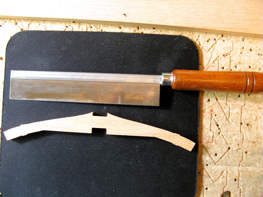
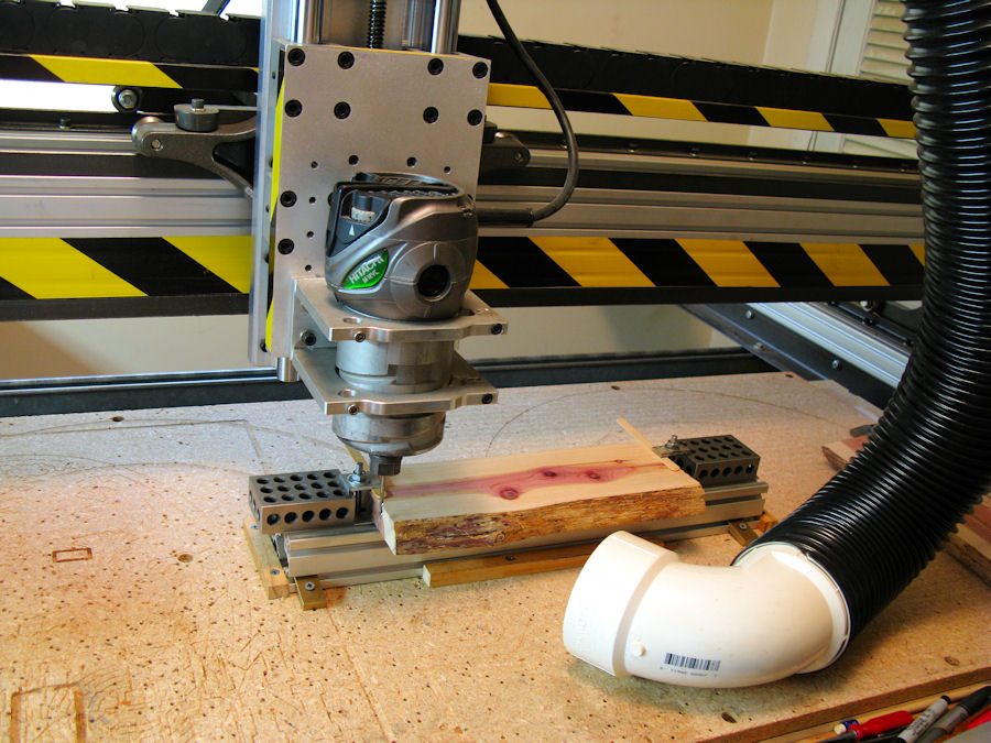
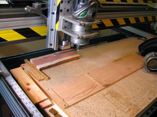
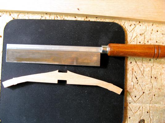
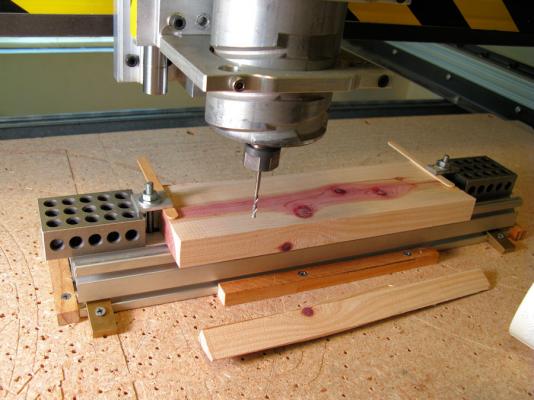
Then......... using my DIY CNC Wood Milling machine, sliced off one part at a time. AL

-
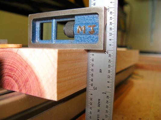
Milled flat on top & bottom. AL
-
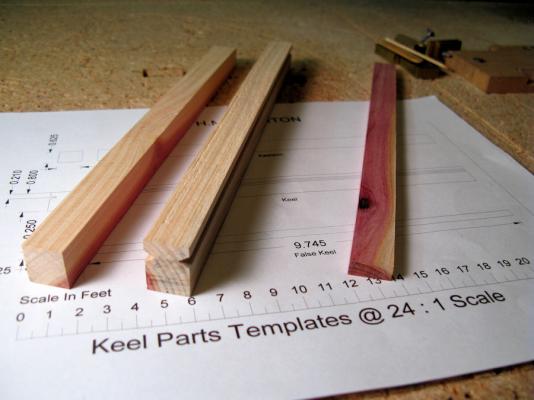
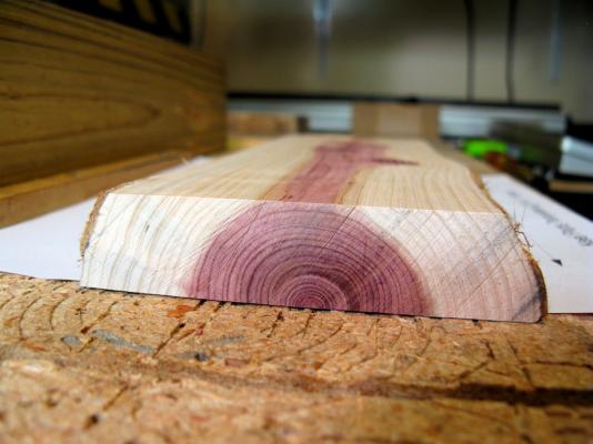
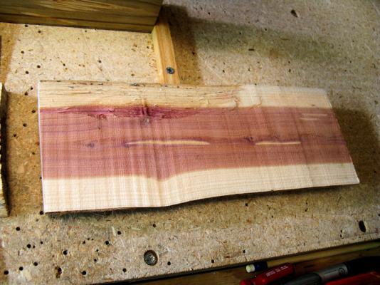
This is what I made the Keel parts shown from...... a chunk of re-cycled Cedar tree! AL
-
Thanks Tim & Pete!! AL
-
Starting my build of the H.M.S. Triton, 24:1 Scale, got the Keel parts completed, looking foreword to enjoying the build, just need permission to access D/L files. And no!!..... that red color on the wood is not blood.... LOL Its Cedar!! I cut a Cedar tree down last year and figured I'd use the wood.....this is my first ship build, so if it don't work out good, no expensive wood will be wasted.... I can always mess up good wood later... LOL And I heard some where that Keel worms don't like Cedar.... LOL Cheers AL