
KLarsen
-
Posts
74 -
Joined
-
Last visited
Content Type
Profiles
Forums
Gallery
Events
Everything posted by KLarsen
-
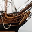 Some more progress. I've installed the wales, the lower one was difficult to bend at the stern but I got it done. I've also gone ahead and trimmed the frames to their (almost) correct height and made the cutouts for the upper gun emplacements (not shown on the first photo which is from a week ago). I'm now turning my attention to the interior, I installed the keelson and will start on the strakes on which the deck beams are resting.

- 55 replies
-
- 11
-

-

-
- ancre
- La Mahonesa
- (and 1 more)
-
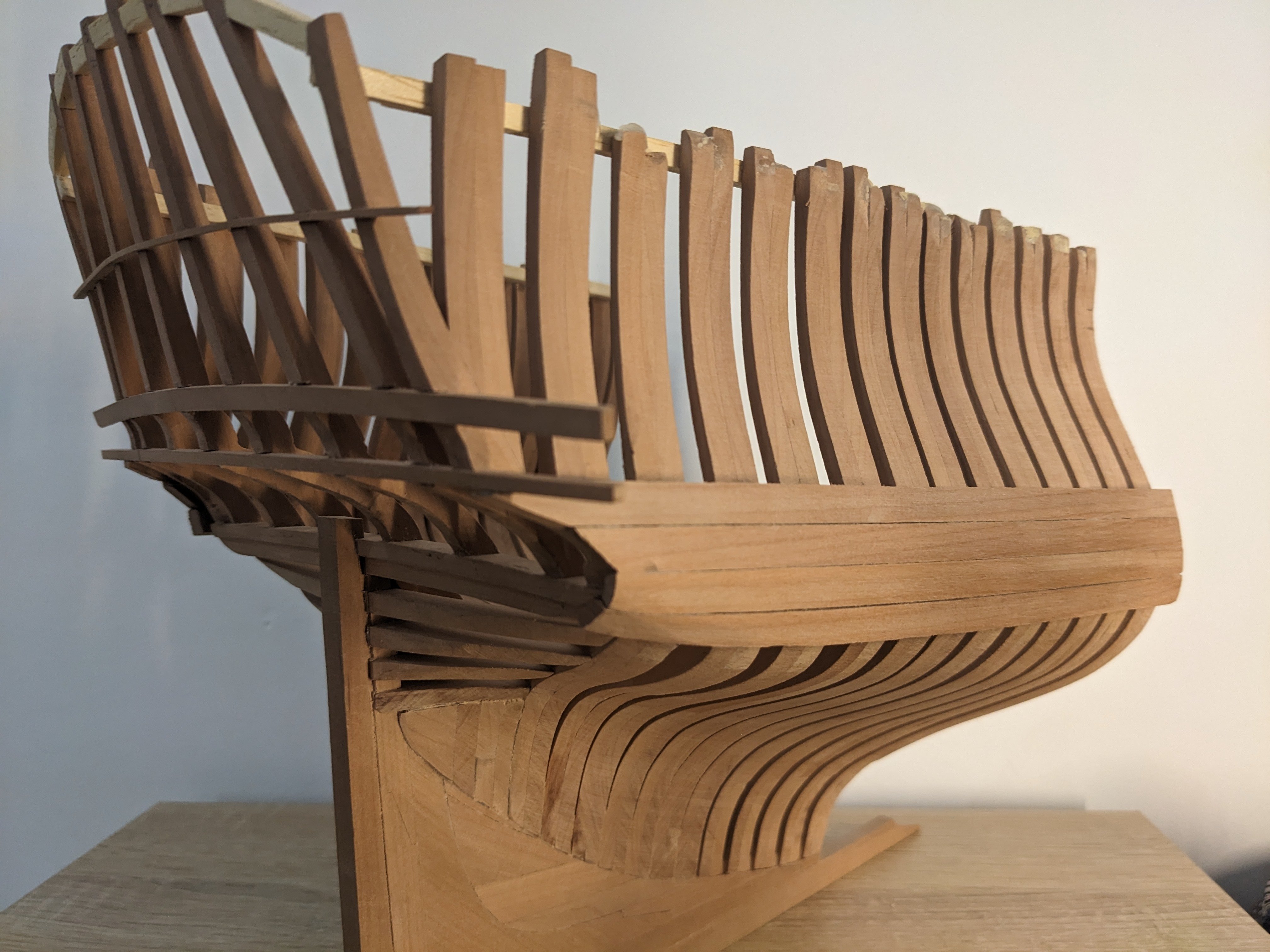
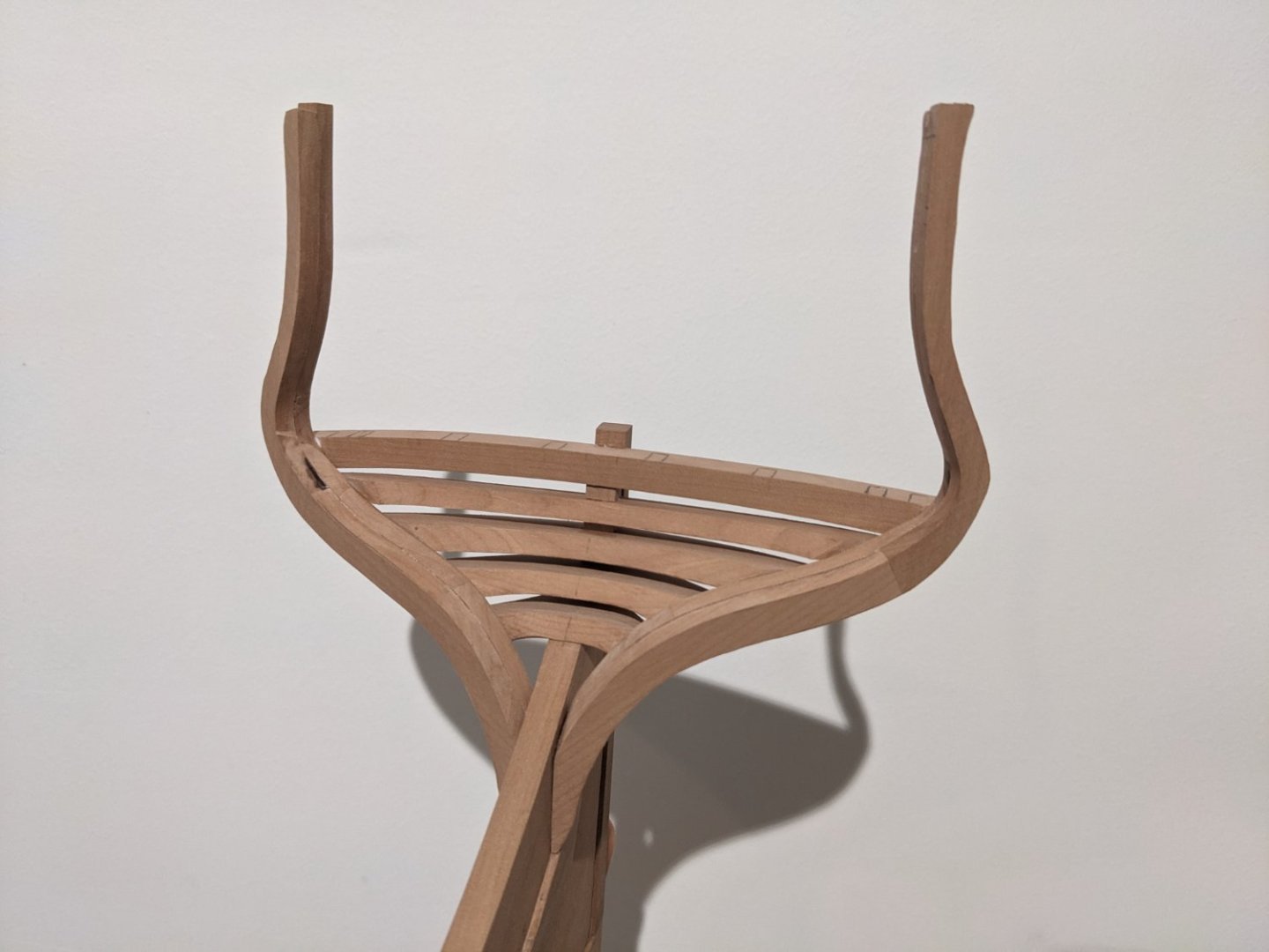
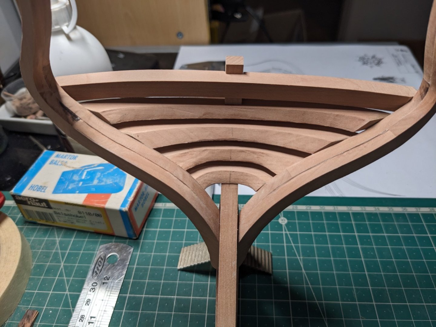
Continuing with the rear frames that will make up the stern gallery. Those stern pieces were a bit tricky to make, I ended up cutting them a few millimeters thicker and sanding them down to shape with the rest of the frames. I think it turned out pretty well! Most of the rough sanding is done, but there's still a lot to be sanded. Sadly I just gouged the yoke a bit this afternoon when sanding the stern, not much I can do about that now though. Also I need to fill out that triangular area below the wing transoms and then sand it all flush.

- 55 replies
-
- 15
-
-
-
- ancre
- La Mahonesa
- (and 1 more)
-
It looks amazing!
-
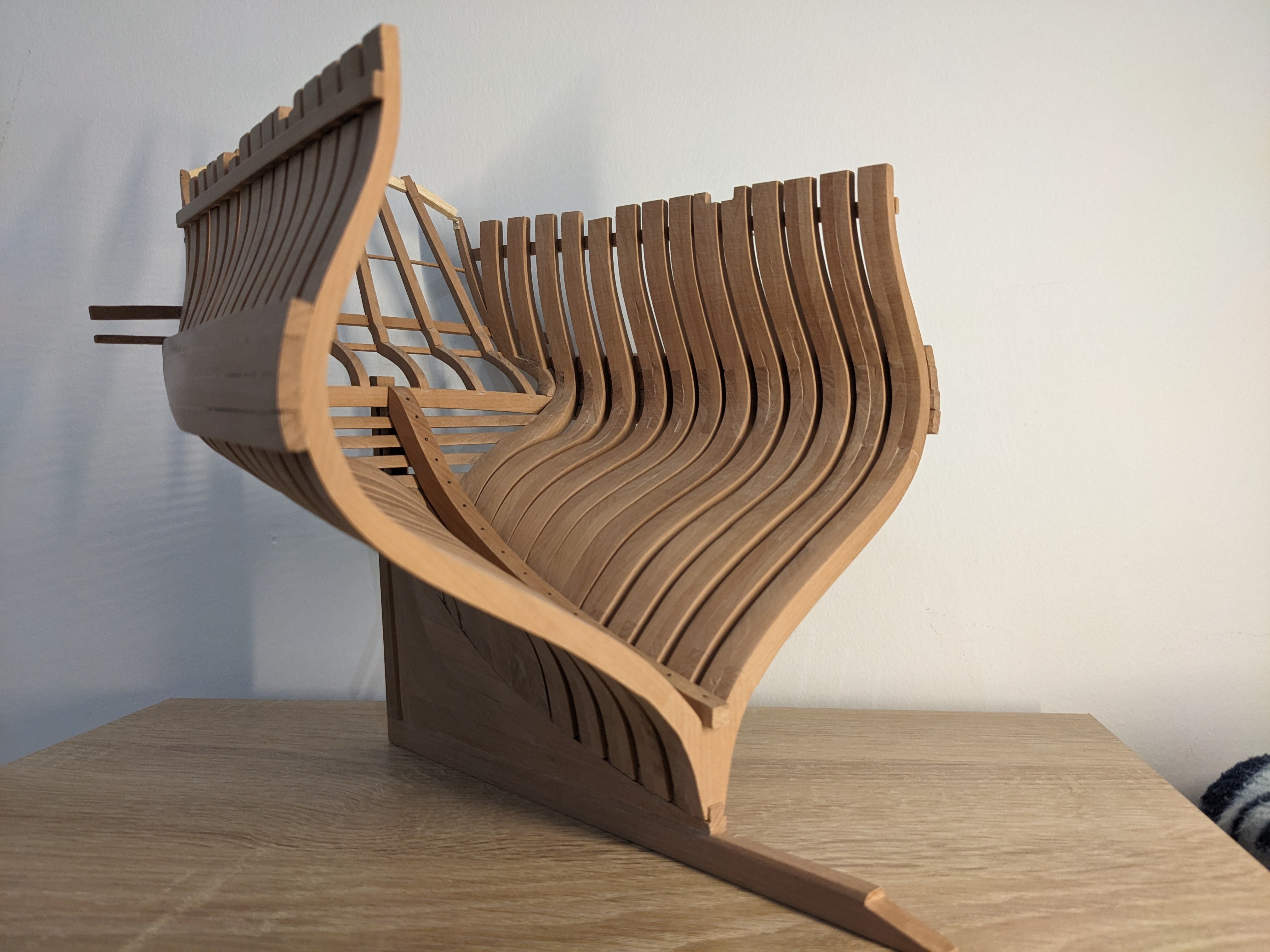
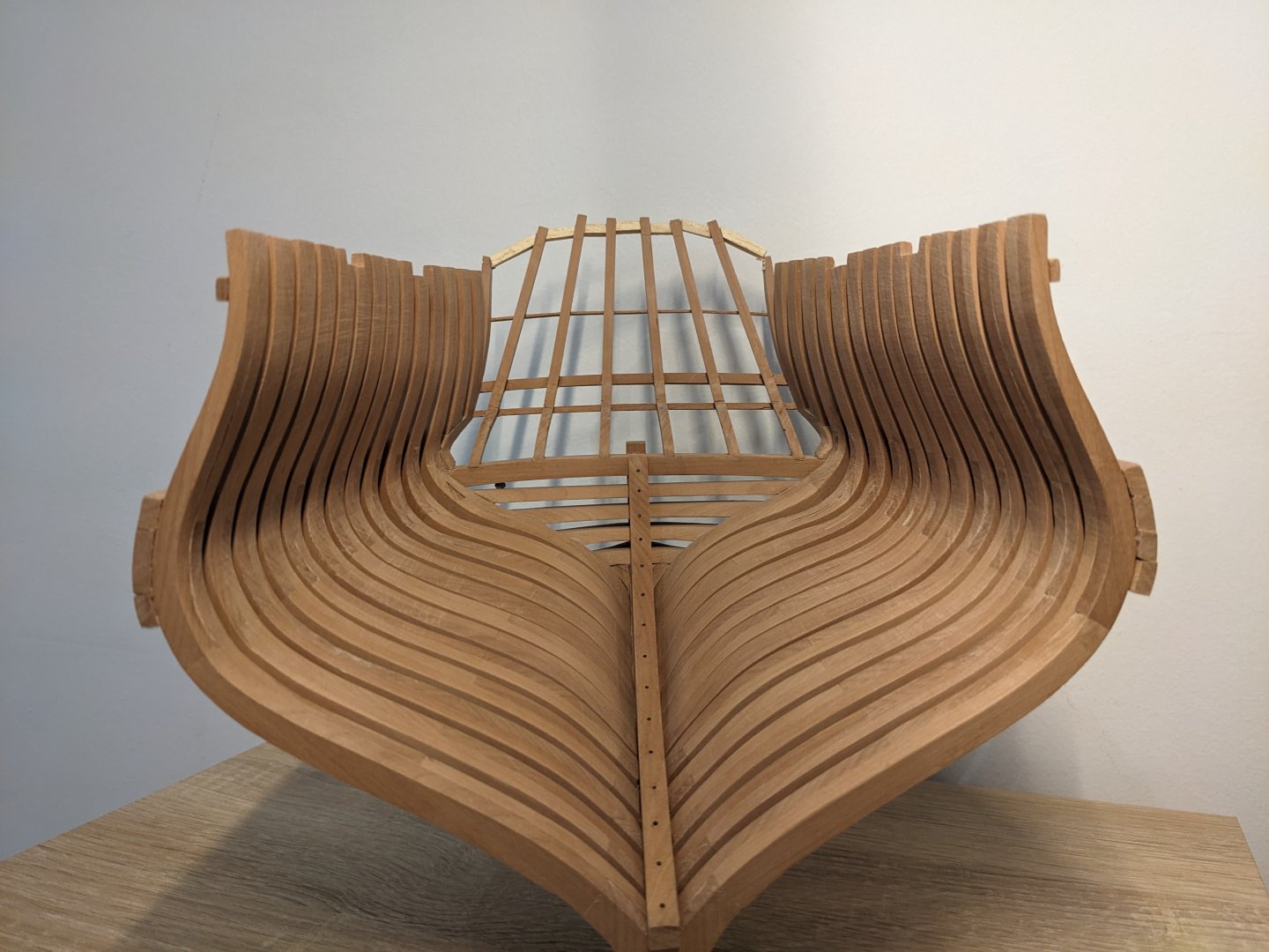
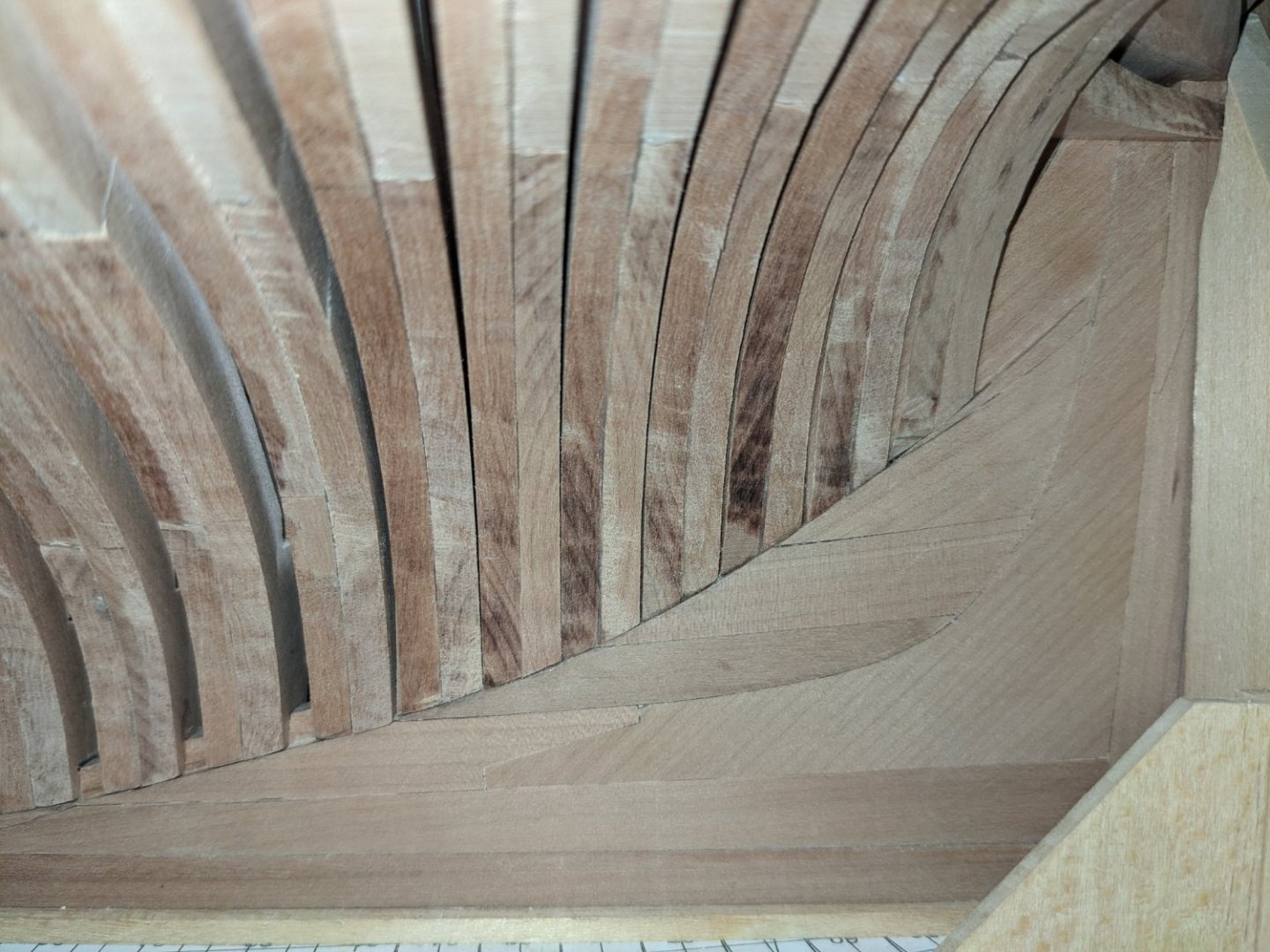
Well that turned out much better than I'd hoped! The hardest part of the frames were sawing all the pieces out by hand, but I eventually got it done (with a sore arm!) and the installation went very well. It definetely helped having a disc sander with a tilting table which allowed me to sand the angle at the foot of the frames with great precision.

- 55 replies
-
- 15
-
-
- ancre
- La Mahonesa
- (and 1 more)
-
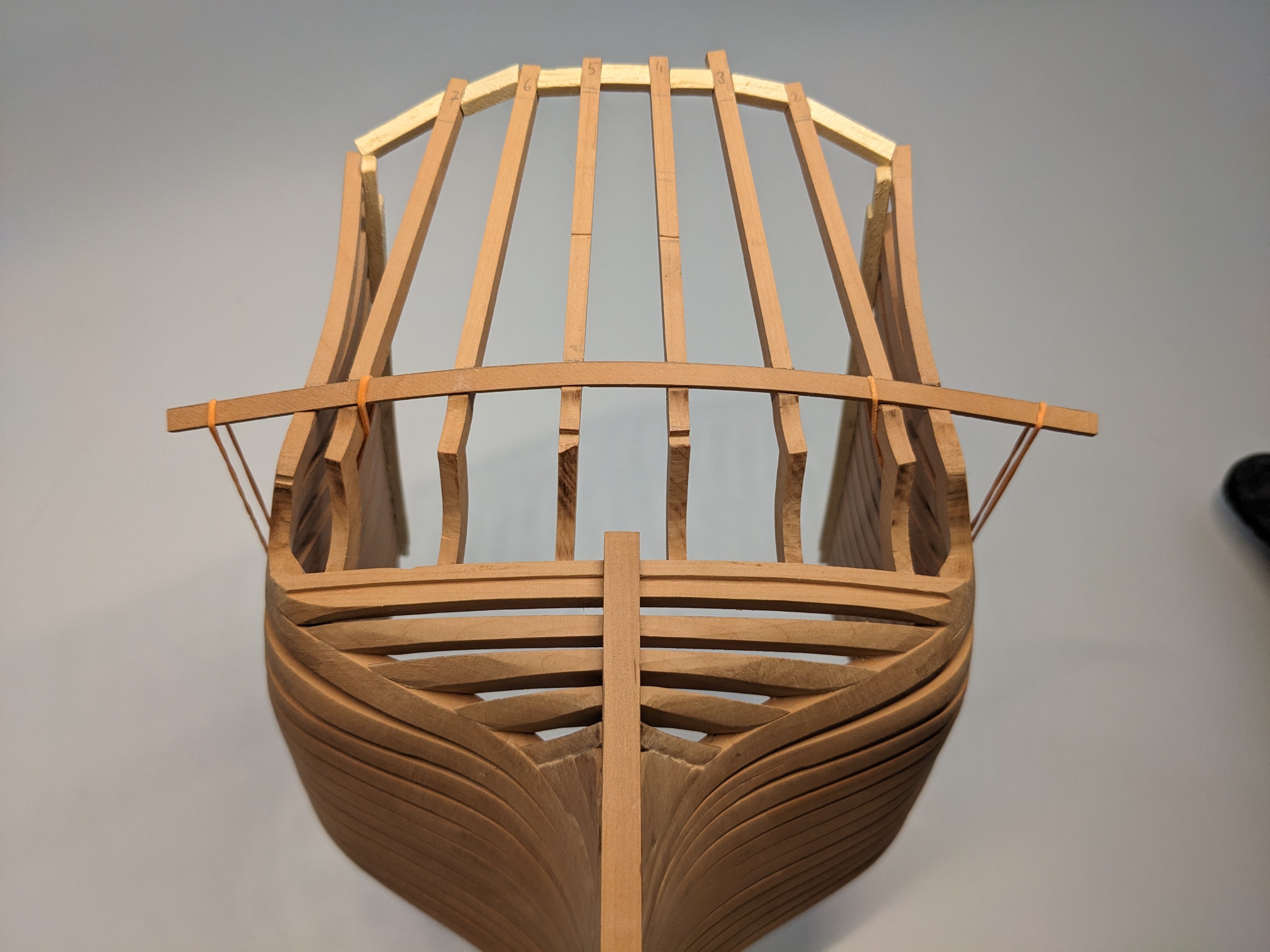
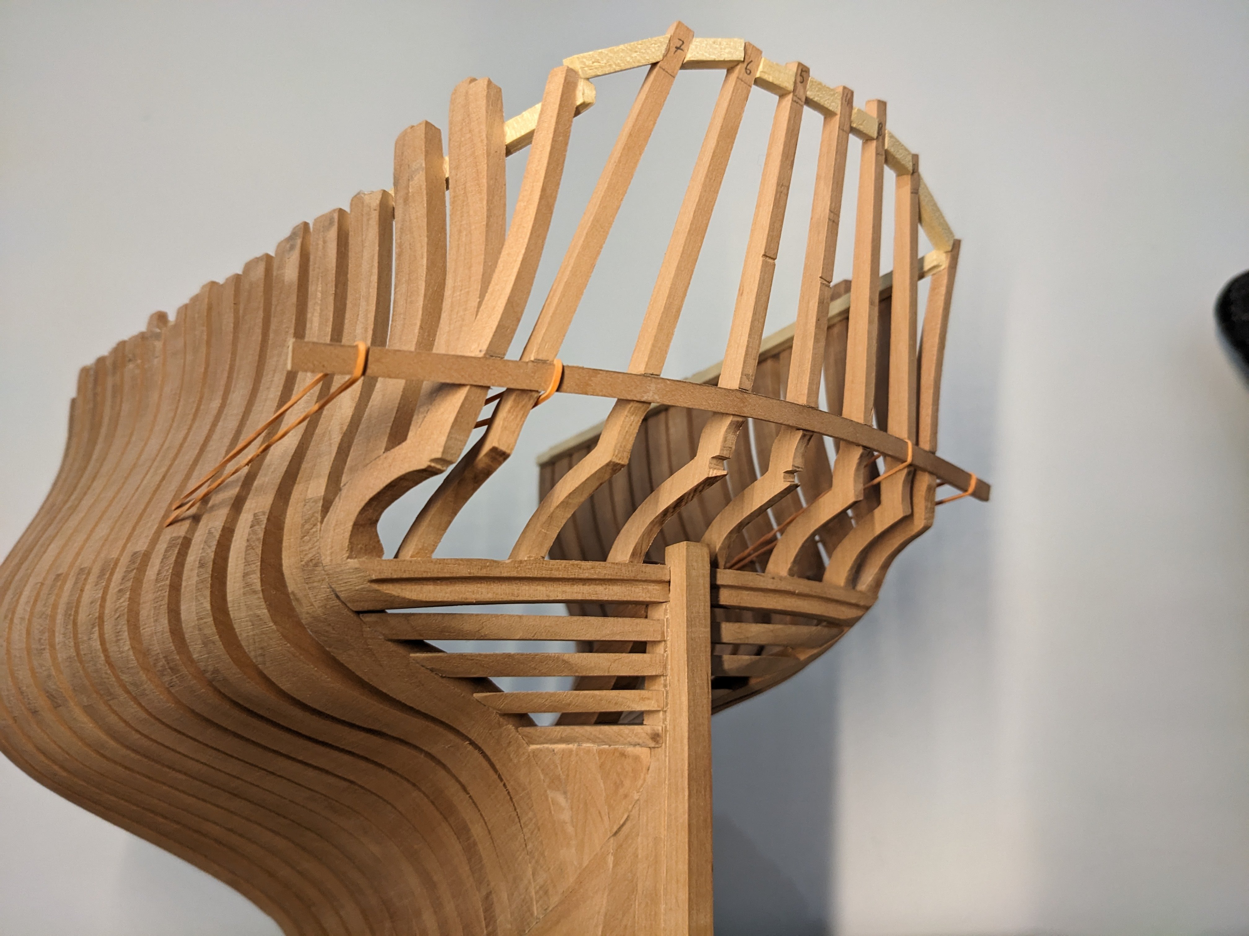
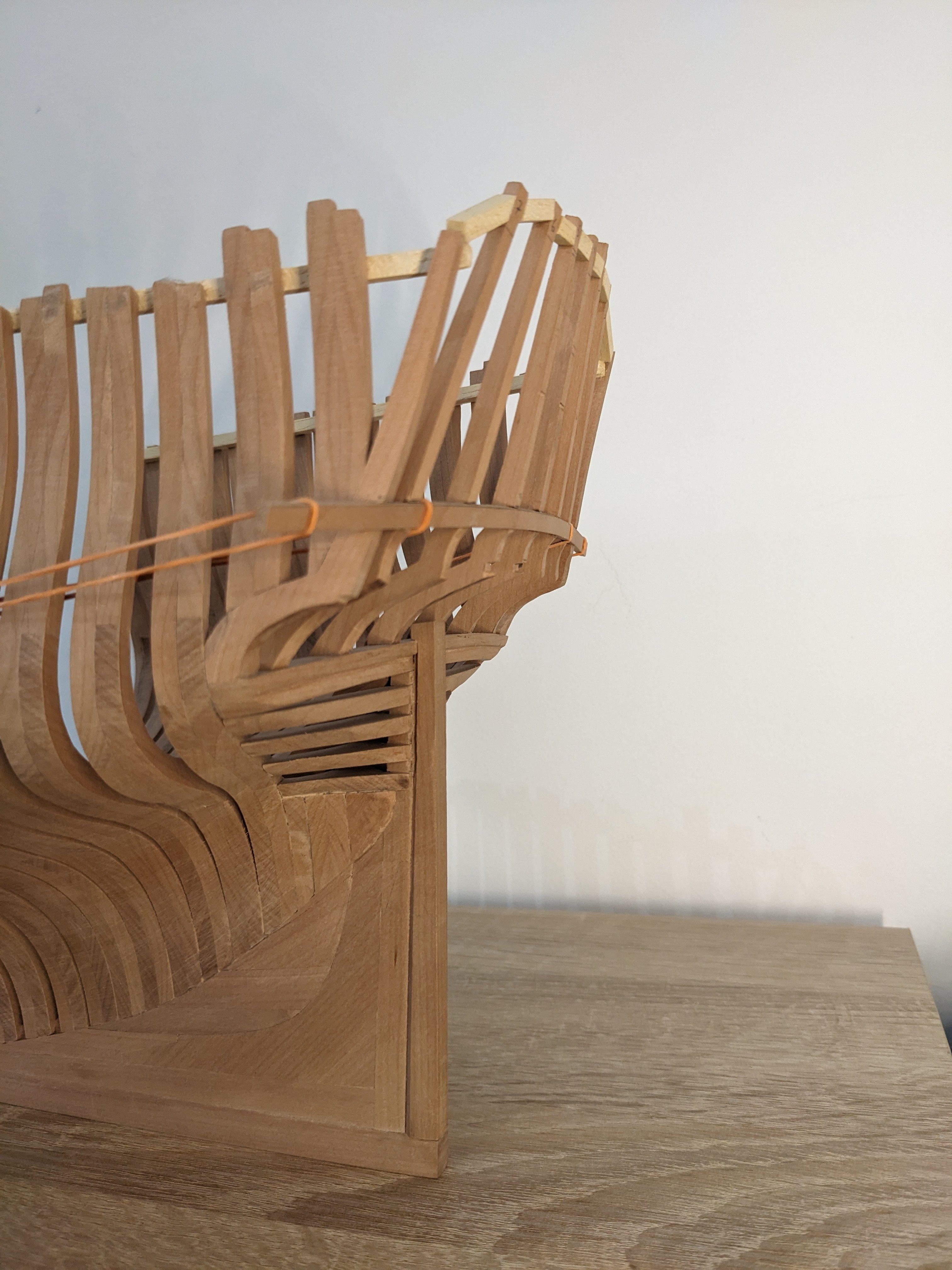
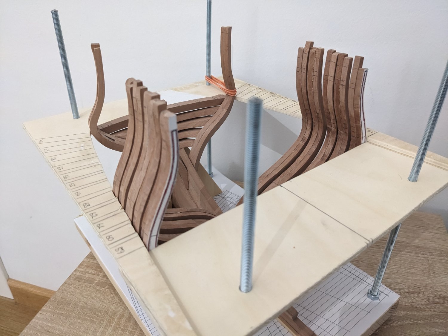
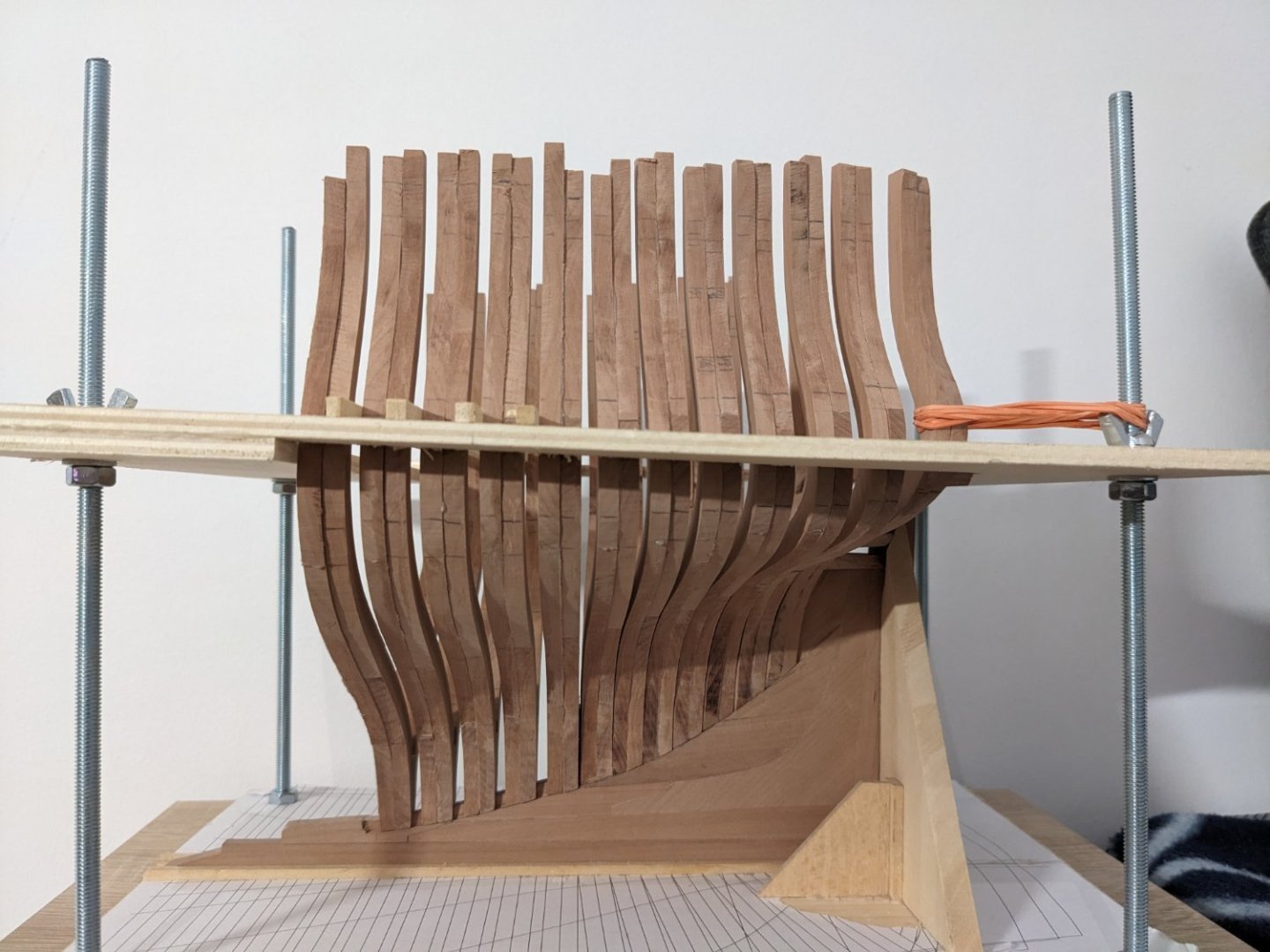
Not much progress lately, only that I built the cradle / building board to attach the frames. Unfortunately I didn't install the last cant frame perfectly well, it's about 1-2 mm off compared to the other side. Probably not much I can do about that now though. I'm using rubber bands to try and force it back a little, maybe when I install the rest of the frames and keep them together with the wales it'll stay in the correct position without warping the whole model. Or maybe not... Honestly I don't feel like starting all over so I'll have to accept it as it is. After all I chose this model to learn how to build plank-on-frame, and this is one of those lessons. Now I'm kind of scared to glue the 5 full frames in, in case I mess it up. 🙃

- 55 replies
-
- 10
-
-
- ancre
- La Mahonesa
- (and 1 more)
-
Looks great, I'll copy your building board, I just need to buy some plywood. 👍
- 55 replies
-
- 1
-
-
- ancre
- La Mahonesa
- (and 1 more)
-
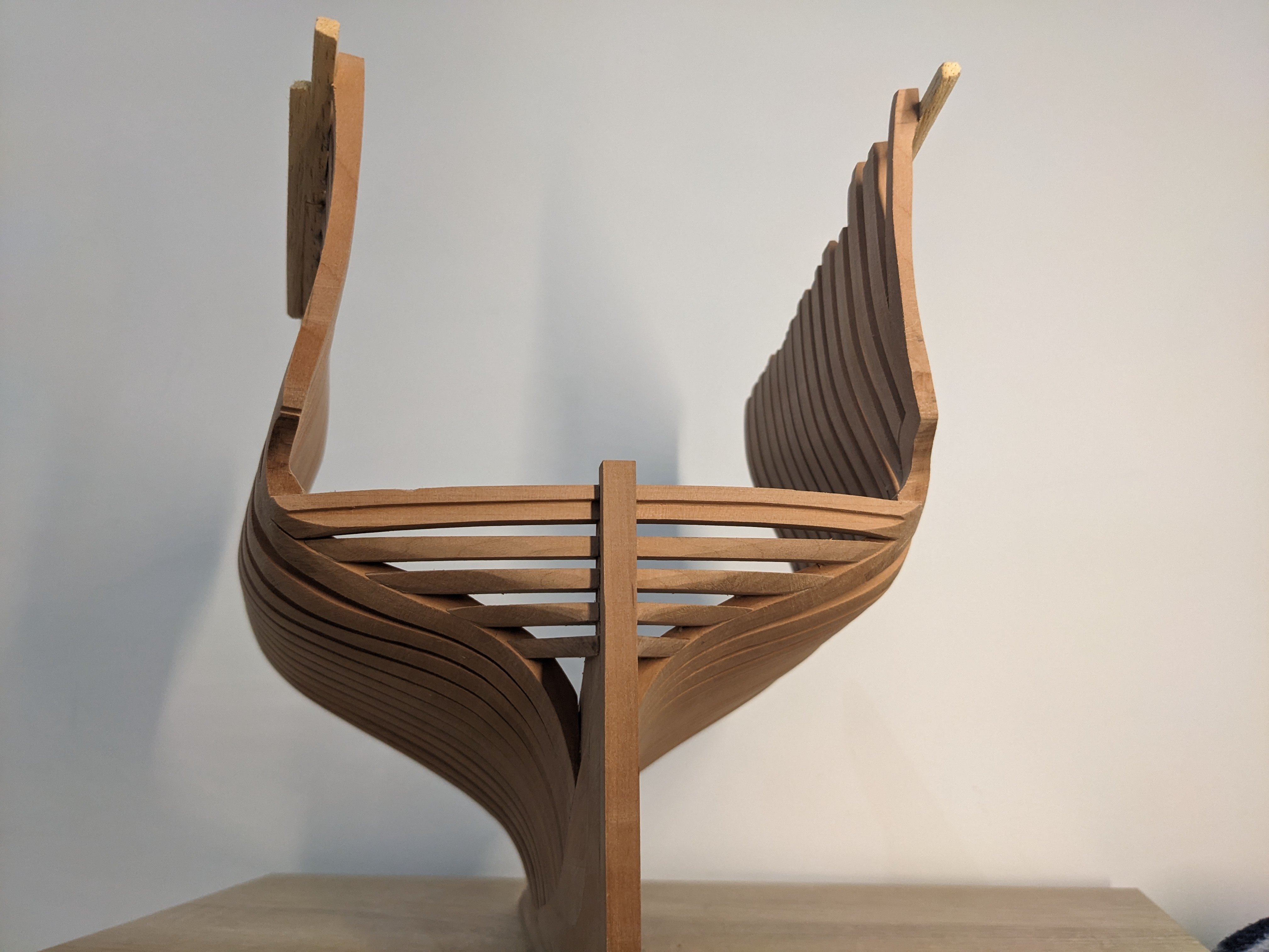
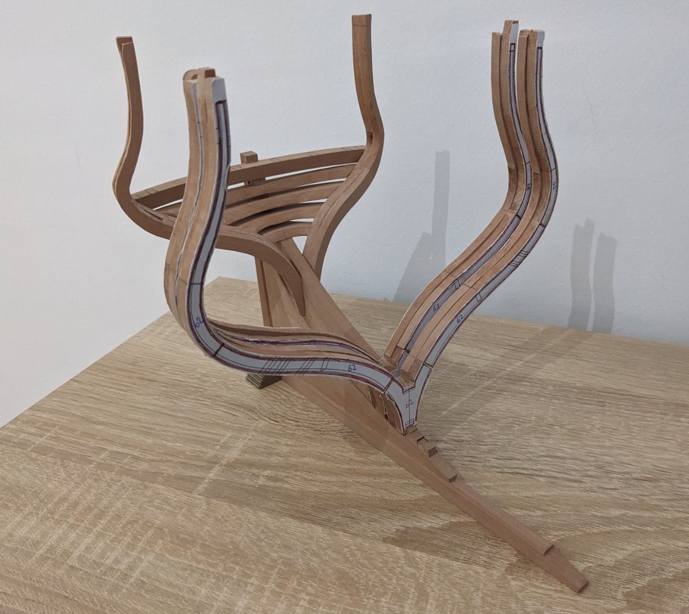
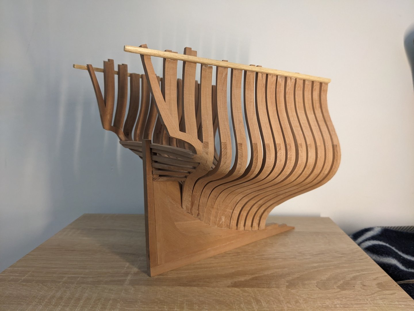
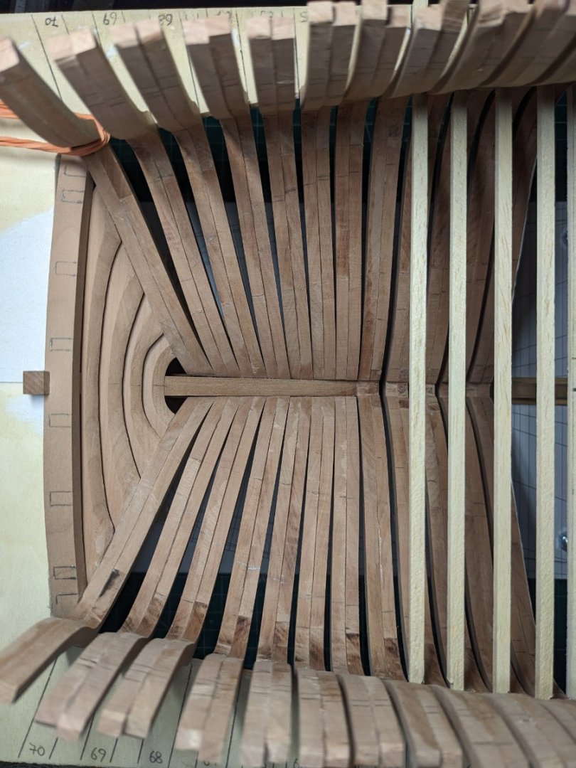
Starting on the full frames. For now they're just dryfitted, it'll be a long time until I can glue them in place. I'll make a building board when I get to that point. Sawing out the pieces by hand takes some effort but it can be done. I've no room for an electric saw where I currently live anyway. Someday hopefully I can have a full workshop for my hobby...

- 55 replies
-
- 15
-
-
-
- ancre
- La Mahonesa
- (and 1 more)
-
It looks amazing! Please keep posting lots of photos, they help me a lot since I'm building a stern cross section of the same ship 😄
-
Thanks! My idea is to make a base plate with a copy of the frame plan on top, and another plate lifted to the height of the wales more or less, where I also trace the position of the frames. Basically as I did with my Santa Caterina build. Would that work? For now though, I'll prepare all the normal frames (just 5 for this cross section) and dry fit them.
- 55 replies
-
- 3
-
-
- ancre
- La Mahonesa
- (and 1 more)
-
I'll make a building board for the rest of the frames, for this last one I used a template made from cardboard to check the correct angles. I've decided not to make bolts this time because the last frame has to be sanded a lot, and I simply don't know where to put the bolts so they don't get sanded down. I had this problem with my last build too (Santa Caterina), where the end frames were sanded almost diagonal. So I've gone ahead and glued the yoke and frame on, I hope I've been precise enough but it's really difficult to judge with all the angles. With this done I can start on the "normal" frames in front of the half frames. Those should be easier to do and can help with aligning the rest of the half frames.
- 55 replies
-
- 10
-
-
- ancre
- La Mahonesa
- (and 1 more)
-
Does anyone have any information on how the frames were bolted together at the end of the 18th century? From what I've found round headed bolts were used in the British navy, but I've seen others use square headed bolted on Spanish ship models. And were the bolts bronze or iron? I'd definitely be easier for me to make round headed bolts but if square headed were used, maybe I can make them somehow.
- 55 replies
-
- 2
-
-
- ancre
- La Mahonesa
- (and 1 more)
-
Yeah I did the same. It's necessary to fix some of the attachments points or it's like a multivariable function. 😄 Did you have any issues with the upper parts of the rear frames not aligning well when you installed the rest of the frames?
- 55 replies
-
- 2
-
-
- ancre
- La Mahonesa
- (and 1 more)
-
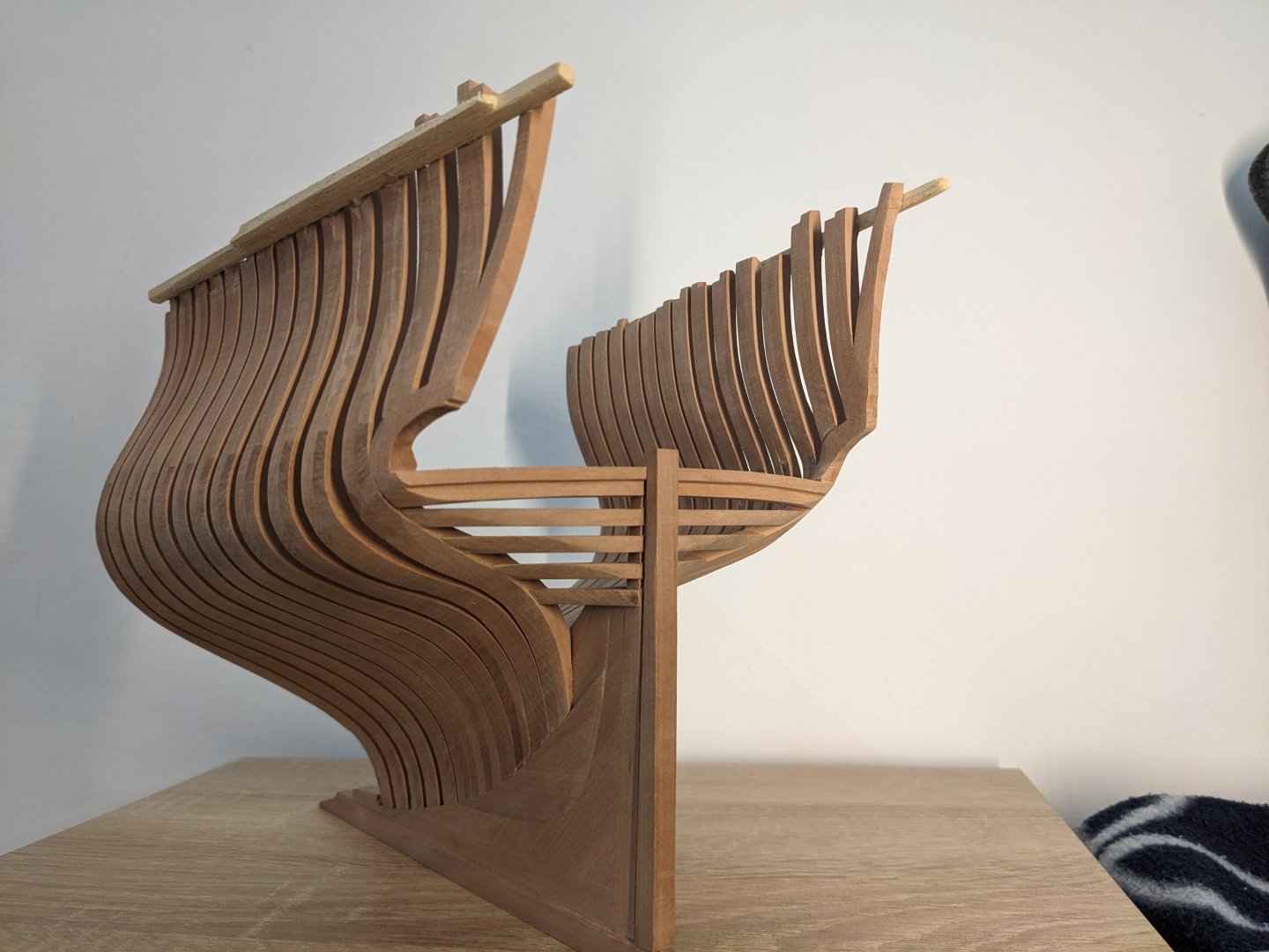
Trying to get the rear frames perfectly aligned seems almost impossible; is there any secret trick to getting it done? The transom pieces have the correct angle, I've sanded and measured them plenty of times and they are fine. I can get the frames to sit almost correctly but there's still 1-2 mm misalignment between the port and starboard ones. I can probably sand that but still. And how do I make sure the upper part of the frames are sitting correctly?
- 55 replies
-
- 5
-
-
- ancre
- La Mahonesa
- (and 1 more)
-
Looking at the plans again with fresh eyes helped. What I thought were the floor timbers are actually the futtocks. Since these are half frames there are no pieces connecting each side. I still need to decide if I want to make the joints at an angle or not.
- 55 replies
-
- 3
-
-
- ancre
- La Mahonesa
- (and 1 more)
-
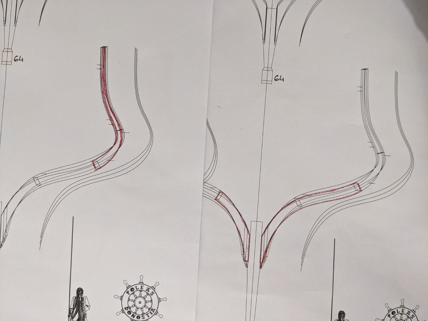
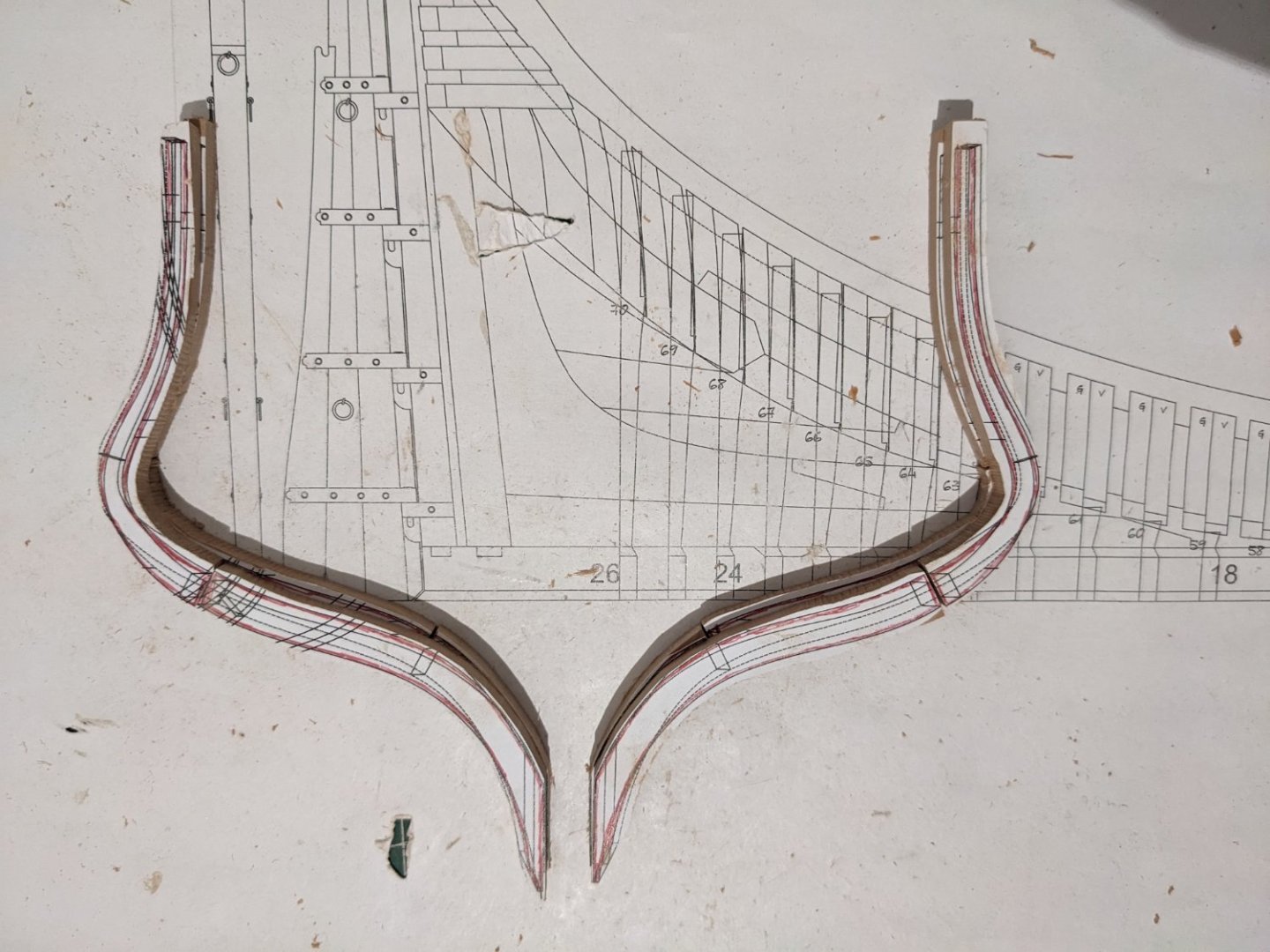
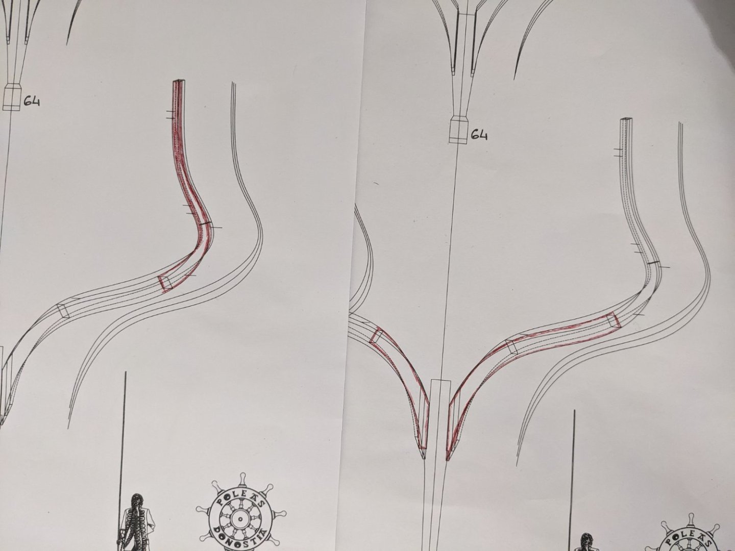
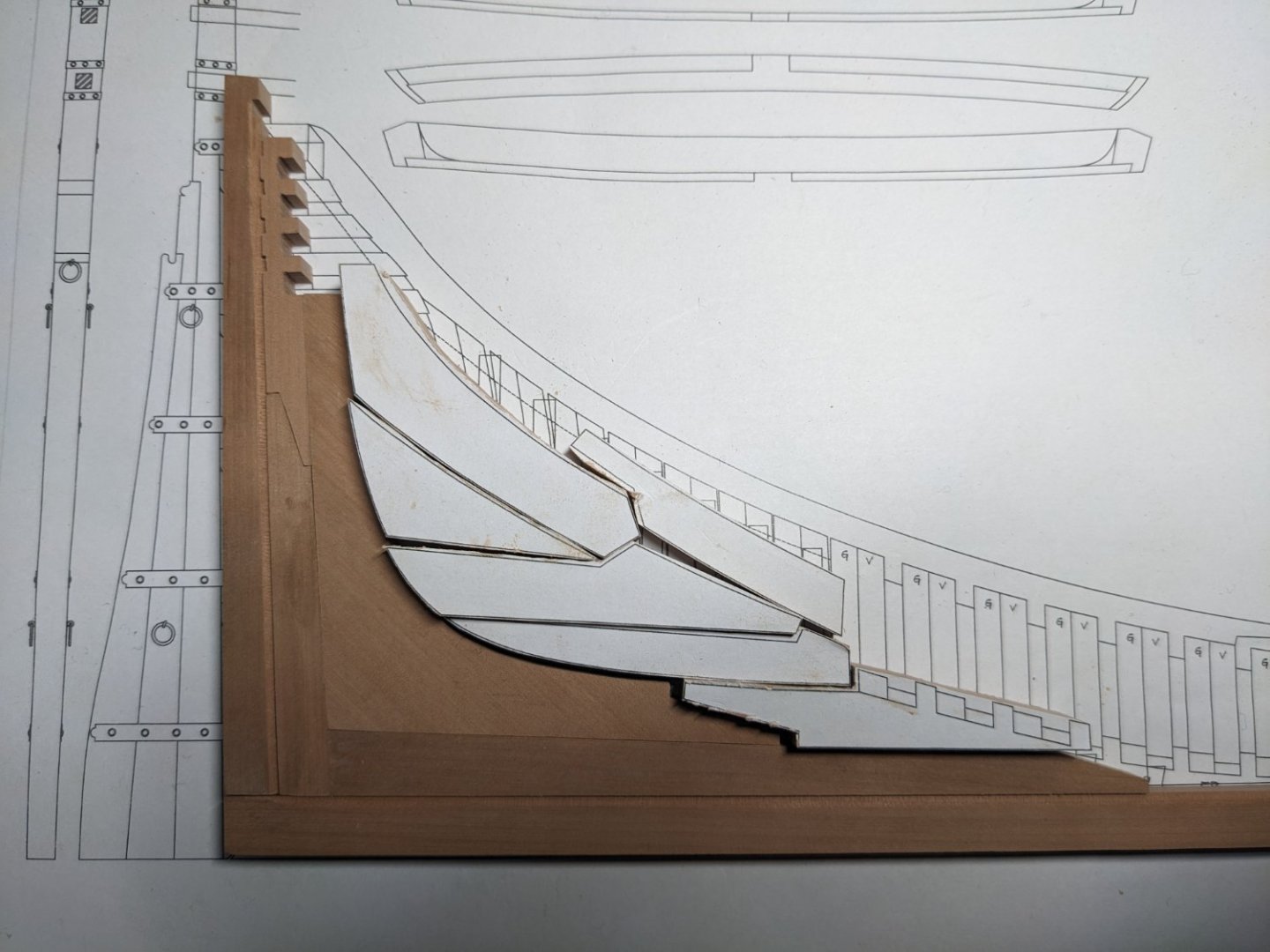
I was wondering if anyone could help me understand how the frames are drawn here: as I understand it, the short pieces or floor timbers face towards the master frame (the stem in this case), while the futtocks face towards the stern. However, the way the frame is drawn here the floor timber sits lower than the futtock. The hull should be sweeping upwards at this point though, it's the very end of the ship. I've tried drawing the pieces in red which is where I'd cut them. But unless I turn them around and have the futtock face towards the master frame they are never going to fit. Another thing: the pieces of each frame are joined at an angle. Is that normal? Would it be wrong to not complicate matters and just make the joint at a right angle? Am I misunderstanding the plans (I probably am, but I can't figure out in what way)?
- 55 replies
-
- 4
-
-
- ancre
- La Mahonesa
- (and 1 more)
-
Thanks! No, I've spent a little too much on tools lately. Also, I don't really have room for it, so I'll try and do without.
- 55 replies
-
- 2
-
-
- ancre
- La Mahonesa
- (and 1 more)
-
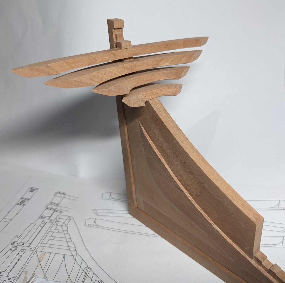
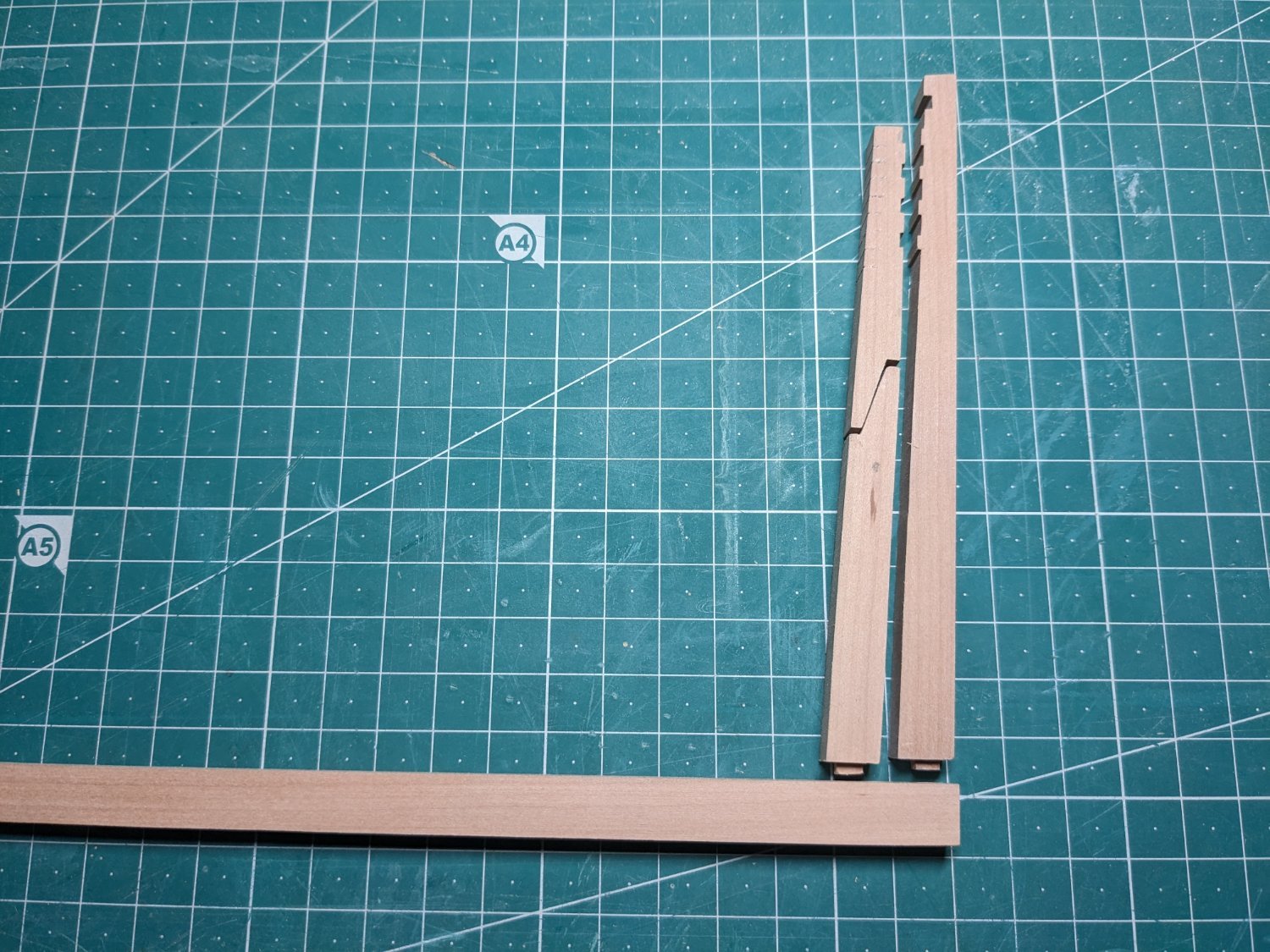
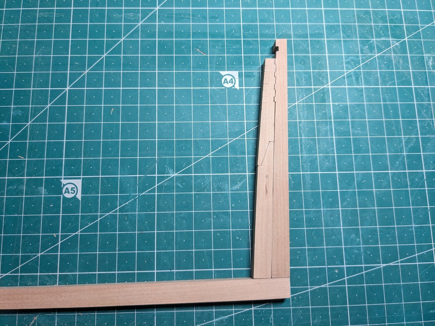
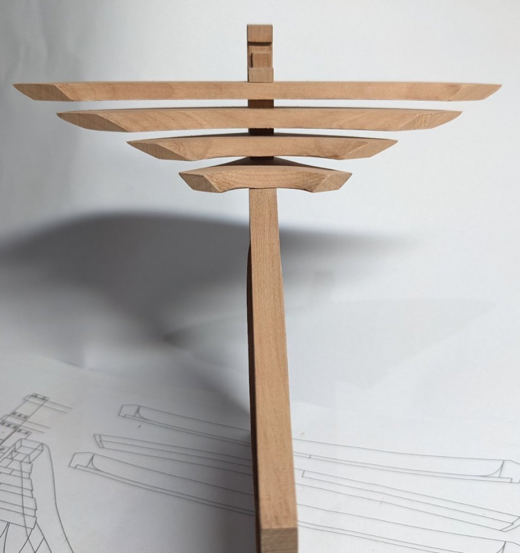
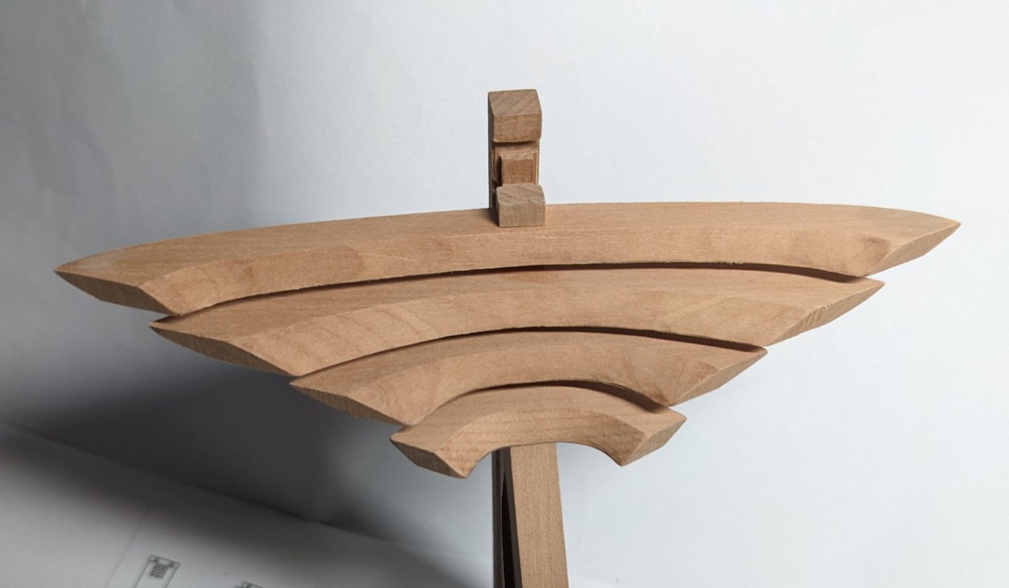
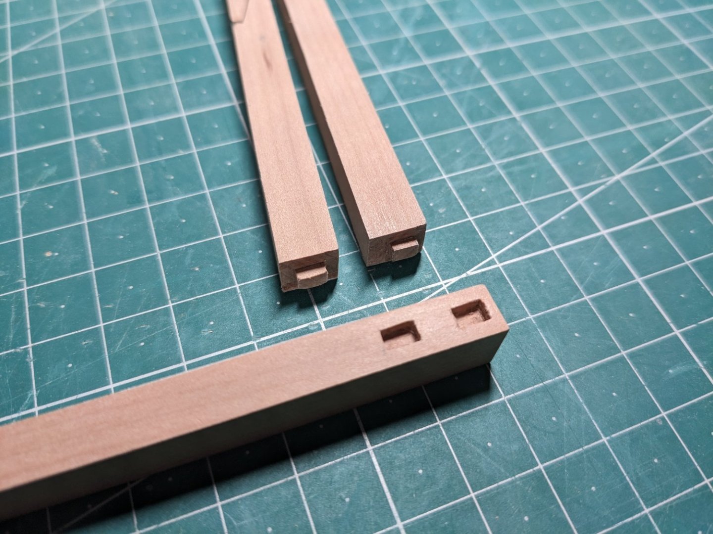
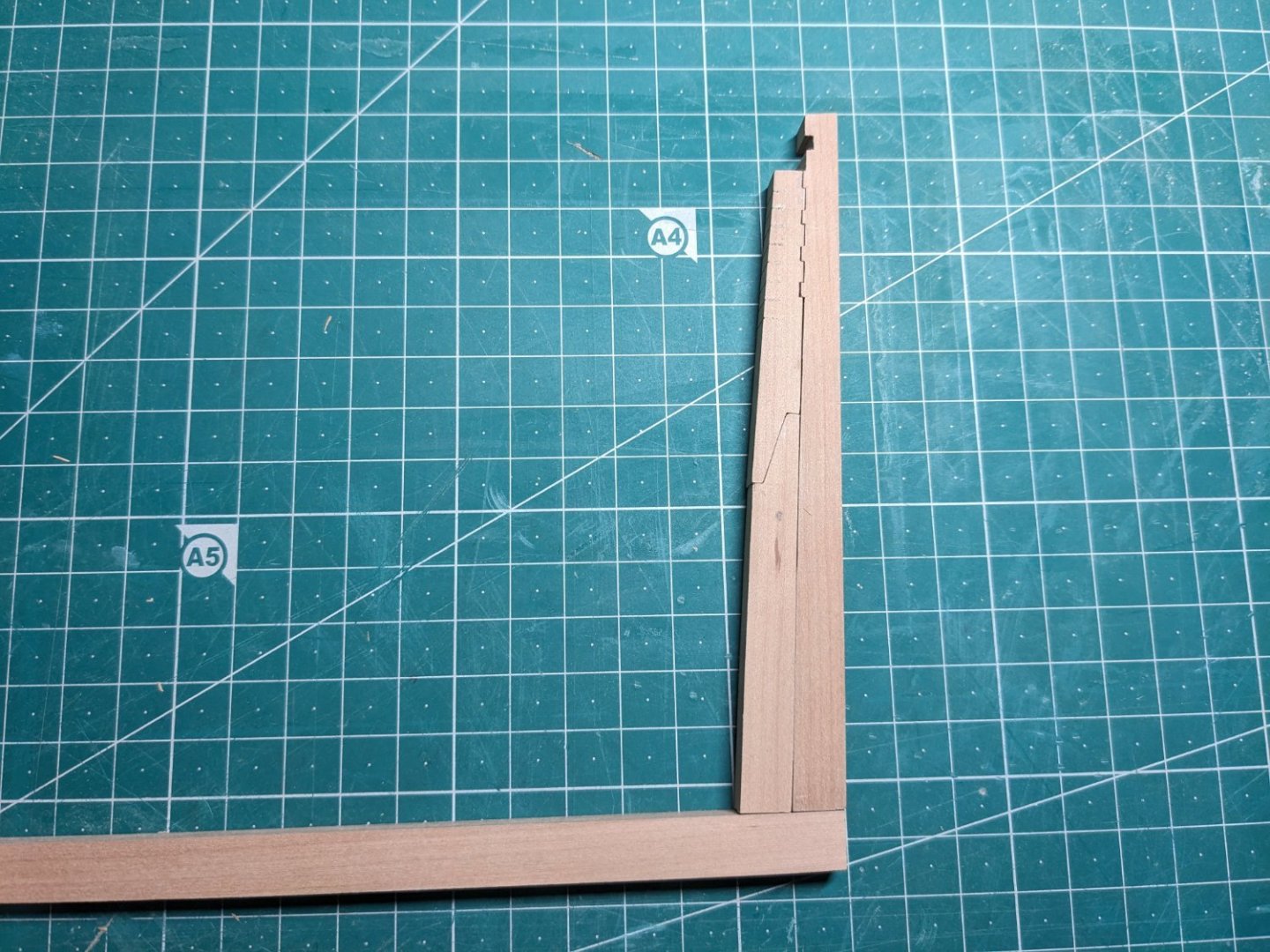
I've created the curve for the rotated frames and sanded the whole keel assembly to more or less the correct proportions. This weekend I created the transom pieces and fitted them, I left about 1-2 mm on the ends so I have something to remove when I eventually fit the last frame. I hope that's enough. I guess the best would be to not glue those pieces in yet, in case I need to change something when fitting the frame? Next up I have to create the yoke (not sure if that's the right name, yugo in Spanish. It's the uppormost transom piece). It is curved in both directions so that will be a bit more tricky to make. Then I can start on the frames, I'll probably make the "normal" frames first before the rotated half-frames, which seem rather difficult. Oh, and I also need to decide where exactly to cut the cross section. I'm thinking around frame 58 since that'll include the wheel and mizzen mast (I'll just install a stump, not the whole thing). Also the cut shouldn't be at a gun port but close to a deck beam. Decisions decisions.

- 55 replies
-
- 10
-
-
- ancre
- La Mahonesa
- (and 1 more)
-
Thank you! I'll see if I can find 2 flute bits, unfortunately the shops around here don't have much to choose from. Maybe I can find them on Amazon though?
- 55 replies
-
- 3
-
-
- ancre
- La Mahonesa
- (and 1 more)
-
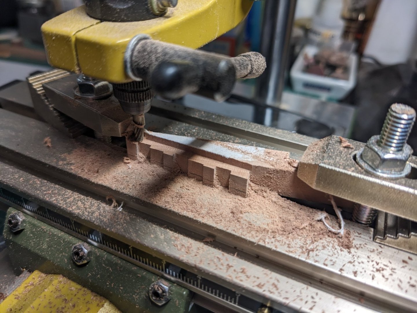
I'm progressing slowly but steadily with the keel: I had to buy yet another tool for this part. It's a manual x/y table for the Proxxon drill and stand. It should allow me to mill much more precise pieces than I could otherwise make.
- 55 replies
-
- 7
-
-
- ancre
- La Mahonesa
- (and 1 more)
-
I already bought a disc sander, and yeah it's invaluable. I can't even imagine having to sand those pieces by hand.
- 55 replies
-
- 2
-
-
- ancre
- La Mahonesa
- (and 1 more)
-
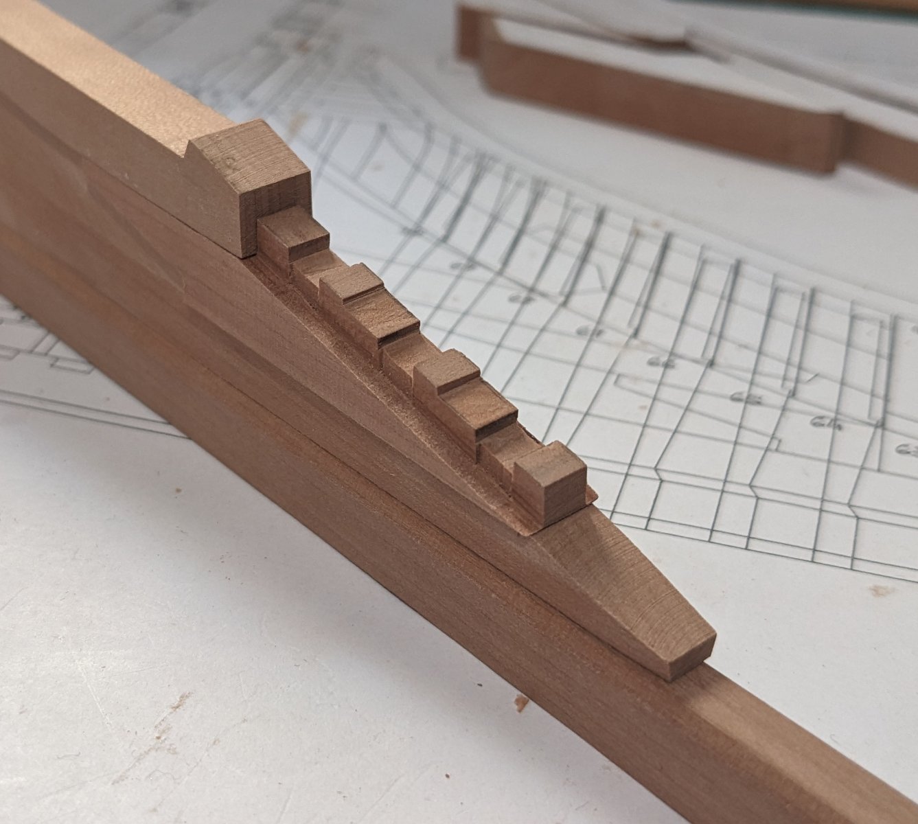
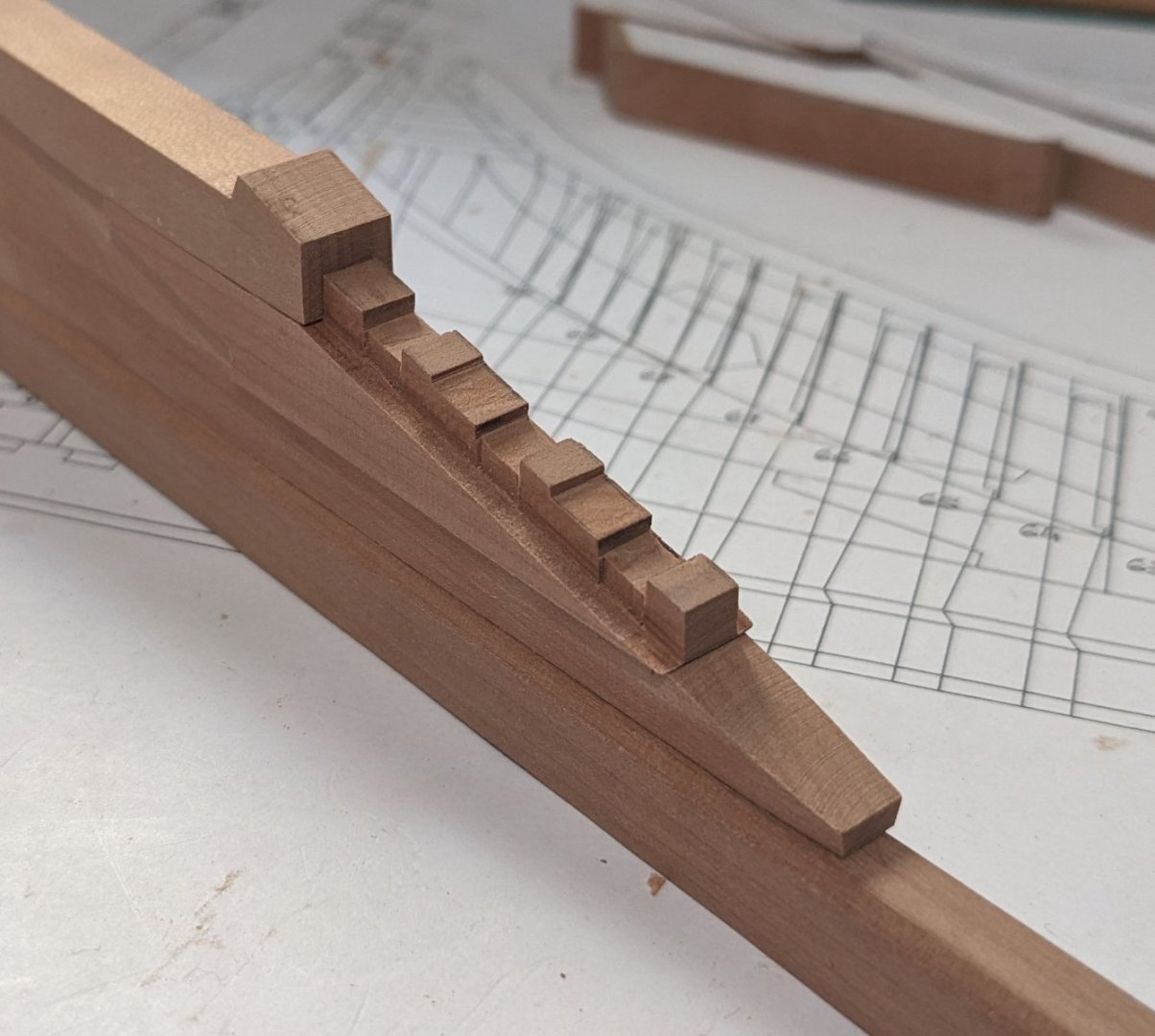
Continuing with the puzzle. Cutting those pieces out by hand was "fun", maybe I should invest in a scroll saw... 🤔 Now I just need to fit everything and then I can sand down the pieces to the correct thickness and slope. Luckily the plans show the slope well, I just need to be careful. By the way, the stern post seems too high in the photo: in reality it's not, I just didn't align it well enough on the plan when taking the photo. The keel is maybe 0,5mm too tall but I can sand that off later.
- 55 replies
-
- 11
-
-
-
- ancre
- La Mahonesa
- (and 1 more)
-
I'm not knowledgeable enough to confirm it with certainty, but it makes sense. The only thing I don't understand then, is why the keel is not distorted in the same view. What I can confirm though is that the frame is indeed seen from the right angle. The lines to the right of each frame shows it from the longitudinal view, and it is narrower there as one would expect. I've been progressing with the stern posts today. Don't worry, I'm not going to detail every little piece of the ship in this blog. 😉 I have a lot of respect for you guys building fully framed ships, these are just the baby steps I'm taking and I'm finding it really hard. I've already had to remake one piece because the template I used got stretched when gluing it on. Still I'm having a lot of fun and am learning, which is the most important!

- 55 replies
-
- 12
-
-
- ancre
- La Mahonesa
- (and 1 more)