Windships
-
Posts
237 -
Joined
-
Last visited
Content Type
Profiles
Forums
Gallery
Events
Everything posted by Windships
-
 Maury I’ll look for the correct color for the bottom. Erik Ronnberg advised me about that for my Rita B. model. It’s an anti-fouling paint.
 -
Notebook I mentioned may have been sold https://vi.raptor.ebaydesc.com/ws/eBayISAPI.dll?ViewItemDescV4&item=154494737018&category=29223&pm=1&ds=0&t=1633029819943&cspheader=1
-
A few thoughts on this intriguing find. Thank you to Charley Green (member of our Southwest Idaho Ship Modelers Society) for alerting our group to it at yesterday's meeting. Hal - My first thought was Underhill rather than Hahn, and that was reinforced by seeing the page listing vessels and basic data, which are all British or Australian. The typeface on the title page is reminiscent of that used for Underhill's Plank On Frame Models, but not identical. If that page was hand drawn, that might suggest the author had drafting training, but... the rest of the pages don't support that notion. The spelling as "Hal" implies somebody's first name. I think the work was dedicated to a friend, or perhaps a son, grandson, or nephew, with the author hoping they would find the author's legacy useful later on. Macquarie, Harbinger, and Cospatrick are all Blackwall Frigates, and mentioned in Lubbock's book of the same name. MacQuarie and Harbinger were owned by Devitt & Moore, and are included in Painted Ports by Course. MacQuarie at least was painted by Spurling, and was among the vessels of my own particular interest when first considering ship modeling. Macquarie and Harbinger appear in Underhill's Masting & Rigging the Clipper Ship and Ocean Carrier, and Sail Training & Cadet Ships. Hmmm... Is the author a Brit, or of British ancestry? Did his interest in these vessels come from reading Underhill, or Spurling's paintings encouraged him to seek data about those vessels? The author's drawings are somewhat like those of McCann, and of Underhill, but...those views are necessary to record the rigging details important to the author. Did he ever build ship models? One of the drawings is specific to Endeavor. Where did he get those details? Publication (somehow) With only a few sample pages, it is hard to tell the value. And, today, we have more sources than apparently were available to this author. Quick Comparison Not long ago on eBay a set of drawings for a steel dragger fishing vessel came up. I forwarded the link to people and institutions whom I thought might have an interest. They are highly detailed, but in sketchbook format, rather than formal shipyard artifacts. The booklet may yet be for sale. Good Luck in the quest for the origin of this material. Thanks again Charley.
-
I find it helpful to make a thin cardboard pattern for the covering board. A lot of trial and error to fit. I get the notches correct then once that piece is installed (in scarphed sections) I install the outboard edge as one long bendable strip.
-
“Here’s Hopin” (Roy Rogers)
-
Very cleanly done Maury. Not an easy task—on a real vessel or a model. Congratulations
-
Lovely can you cut those holes on your mill? I don’t have one so forgive me if a dumb? will soon face the same issue on my sloop
-
Mike take a look at the colored pencil drawings I sent you a while back. They explain how everything goes together: frames, beam shelf, deck beams, planksheer, margin plank and etc. helpful to sketch your own reinforces your understanding or make a mock-up nice looking Hannah dvm27!
-
Wiseman’s craftsmanship is phenomenal no matter what his subject is. I too, saw some of his models at Mystic in 2019.
-
I will guess you’ve not had access to my article. This Leavitt is the son of the Leavitt who built two models named Hannah. I’m traveling and only have use of my IPhone so I don’t have easy access to images. But in short, those Hannah models were heavily influenced by an 1865 model named Friendship, including the color scheme. As was an obscure painting by Leavitt (“Sr.”) also reproduced in my article. Which brings us back to your comment: conjectural. Sadly, once a painting or a model made by someone at that time who is considered to be an authority is given the name of a vessel, that image sticks. And all too often, undeservedly. Much, much more about how this came about for Hannah in my article... That said, unless one was willing to challenge the conventional wisdom, they would have done just what you did. Run with what is readily at hand. That’s what I did with my 1970 model I named Hannah and it is incorrect for essentially the same reasons the Hahn models are, and the Smithsonian model. Thanks I’m very grateful for any comments. Just difficult to properly respond on my iPhone Home 14 July.
-
Good Morning always an inspiration to see your fine work Mike. Rigging... I didn’t provide masting and rigging plans on purpose. Why not? First, I don’t presume that my depiction is precisely what this Hannah looked like. No one knows. Only that the primary record is more fully supportive of what I presented. Im confident that had Harold known what I learned his model would be different. Harold’s strong suit—by his own admission—was not rigging. As a point of departure I suggested Chapelle’s Sultana rig as drawn for the Model Shipways kit. Ronnberg’s Fair American is a great reference too as are his unpublished drawings of his Hannah model from Wm A Baker’s design. Other aspects are noted in my article. My hope was this new look at Hannah would encourage others toward further examination and even different interpretations of the data where supportable. One could rig her with only “four lowers”. Or with a fore topsail v fore and main. Should she have gaff topsails? The answers are not clear from contemporary illustrations. She might have had a lumber port in the lower transom. Her armament remains an open question as to weight of shot and how the carriages were mounted. I think its been 90 days since publication so I now hold the copyright. However to distribute the piece certain illustrations will have to be removed unless I secure permission and pay for them to be included. Of course the best way to view the entire piece is to join the NRG. Hope this was helpful. Mike and I will continue to work out the wrinkles. Last, yes, doing things in sequence is essential and always requires forethought and planning. Questions welcome any time. ——- To be candid, I didn’t intend to make the Drawings set either but glad I did. Ironically it is only the Drawings and Mike’s choice to build from them which have elicited comment. To the best of my knowledge no one has remarked about anything else in the 230 page monograph. Come to your own conclusion about whether the underlying research means anything at all to most of our community so long as drawings depict an attractive modeling subject. No one seriously investigated Hannah until Smith and Knight in 1970 and they were essentially ignored by our community. Until my work no one questioned Harold either... Sad in each case because there is always something yet to be discovered. And in the meantime we labored along under significant misconceptions about this Hannah.
-
A very well-done, WELL, indeed!
-
Steamboats and other rivercraft - general discussion
Windships replied to Cathead's topic in Nautical/Naval History
Thanks Kurt ill check but, I think I have visited that site. Always worth another look- 281 replies
-
- 3
-

-
- Steamboats
- riverboats
- (and 3 more)
-
Steamboats and other rivercraft - general discussion
Windships replied to Cathead's topic in Nautical/Naval History
Catching up... I have not been successful in locating useful materials from the places offered in the posts above. But I thank all of you nonetheless. Grafton, Illinois Near the confluence of the Illinois and the Mississippi, and just above St Louis. This place had a very active boat and shipbuilding industry from 1874 until 1982, including Vietnam War riverine assault vessels. I am in touch with the local historian there (87 years-young) and hope to learn more. Just today they are opening a new museum at the visitor center. A collection of glass plate negatives came to them when the shipyards shut down, but few have been printed due to high cost. I learned from the 1870 US Census (my wife's research) that the Master Carpenter (James Heywood / Haywood / Harwood) who built the Z. Biddle in 1878 at Griggsville Landing, was also living and working at Grafton. Speaking with the historian, I learned that Grafton was perfectly capable of completing the hull of the ferry (boiler, engine, stern paddlewheel). So, my new working theory is that she went from Griggsville Landing, downriver to Grafton, had that work done, thence to St Louis to be registered. From there, back upriver on her own power to Valley City/Phillips Ferry on the Illinois. All that said, still no description or photos!! Biddle ADDITIONAL REFERENCES - thanks to Kurt for leading me to the second one, which in turn helped me find the first one. https://mohistory.org/collections/item/A0428 Records of the Eagle Packet Company http://www.umsl.edu/mercantile/collections/index.html Summary of the Collections of the St Louis Mercantile Library The National Park Service report on the History of Grafton, Illinois (located with help from my wife) is remarkable. I had no idea they created such useful materials Grafton Illinois - NPS Survey - History of Grafton.pdf- 281 replies
-
- 2
-
-
- Steamboats
- riverboats
- (and 3 more)
-
Steamboats and other rivercraft - general discussion
Windships replied to Cathead's topic in Nautical/Naval History
Thanks!- 281 replies
-
- 2
-
-
- Steamboats
- riverboats
- (and 3 more)
-
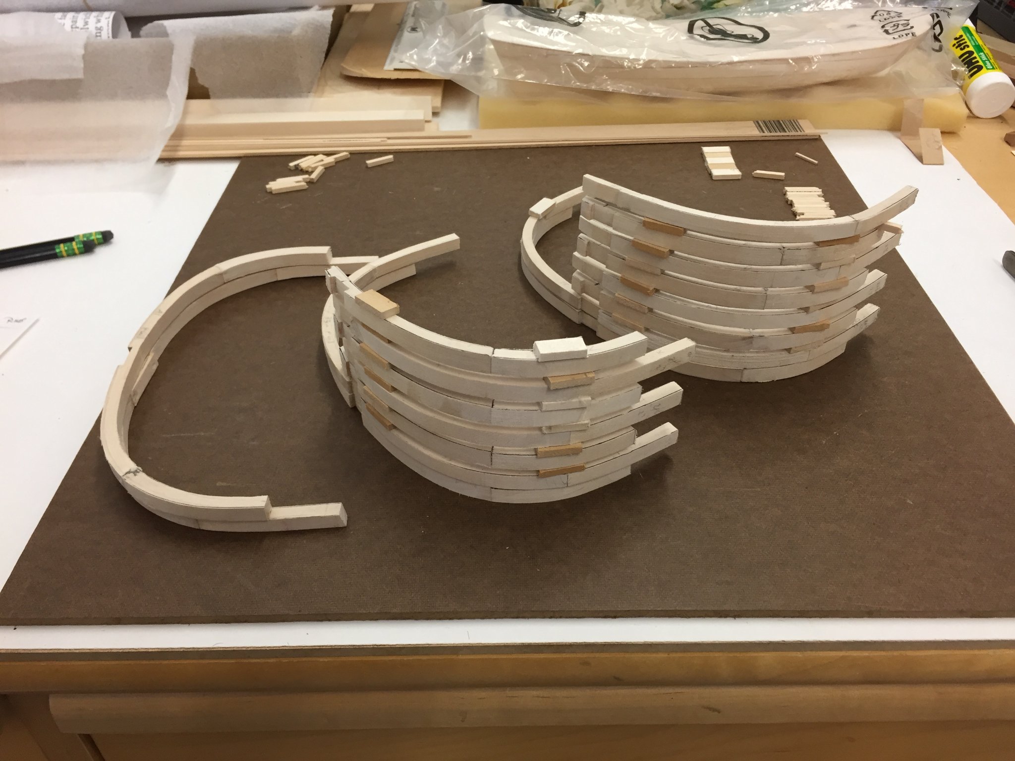
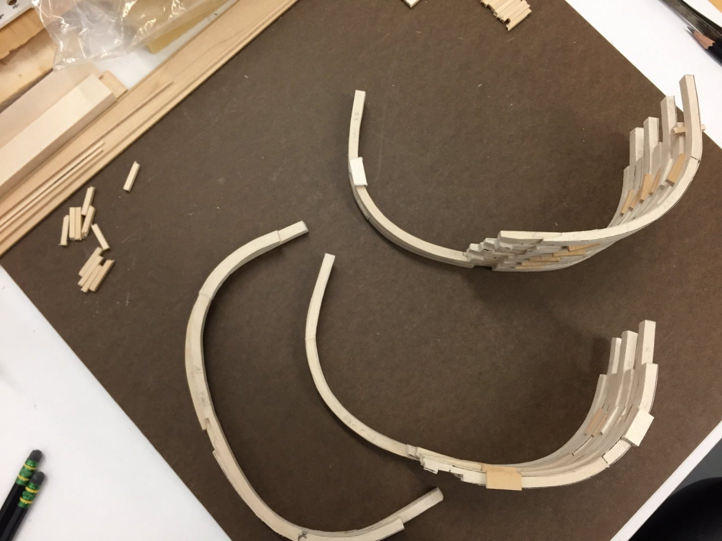
I formed these frames on the Dremel rig I mentioned. They are at 1:32 Composed of Floors and 1st, 2nd and 3rd Futtocks, plus a chock between Floors and 2nd's and First's and 3rd's. Some are single frames and others are double. If I had more space to display models, and wanted to build POF, I think this is an excellent scale. Clay Feldman used it as well.

-
Steamboats and other rivercraft - general discussion
Windships replied to Cathead's topic in Nautical/Naval History
Anyone know where you can find the actual report from a steamboat inspection rather than just the mention that an inspection took place? Thanks randy- 281 replies
-
- 2
-
-
- Steamboats
- riverboats
- (and 3 more)
-
Mike Your drill press set up reminds me of my Dremel 20-year-old router table which I set up inverted and used as a shaper/spindle sander. Very fine work you are doing!! randy
-
Steamboats and other rivercraft - general discussion
Windships replied to Cathead's topic in Nautical/Naval History
Very useful post re construction of flatboats. The upside down building method also popular with some for San Francisco Bay scow schooners. Especially those constructed using fore and aft chine logs (ALMA, 1906) rather than framed like my Gaslight, 1874. The post gives me insight as to how the Z. BIDDLE may have been built as her proportions are more barge or scow-like. Thanks- 281 replies
-
- 3
-
-
- Steamboats
- riverboats
- (and 3 more)
-
Mike! I am greatly impressed at your careful, thoughtful planning and excellent craftsmanship! And, relieved that the drawings are holding up for you. The little schooner herself is beginning to emerge in three dimensions...
-
Steamboats and other rivercraft - general discussion
Windships replied to Cathead's topic in Nautical/Naval History
Z. BIDDLE - Illinois River Steam Sternwheel Ferry NARA in Kansas City located the Master Carpenters Certificate for this vessel - August 10, 1878 - James Heywood/Haywood Pittsfield Public Library - Reference Librarian located this fellow in the 1880 Census. Born in New York, lived in Valley City, Flint Township, Illinois - right near Griggsville Landing where the vessel (the hull at least) was built. Wreck Report - none have been found. Inspection Reports - Several were made, but no actual reports/data discovered yet. Still searching for descriptions/sketches/drawings or photographs. Abraham Lincoln Library - Springfield - has a very good run of early Griggsville newspapers, but cannot provide scans in large numbers from their microfilm remotely. Hopeful of a relative in the area doing some in-person research at that library. This morning in an 1891 volume about Pike and Calhoun county luminaries, I learned that there were "old steam barges" working on the Illinois as early as 1831, and there was a newspaper in operation in that area with a steam powered printing press. Some early barges were built from trees (duh) cut with a whipsaw. Later, of course steam saw mills... Current thinking - given the relatively narrow Illinois at the crossing in question, and the smallish hull dimensions of the Z. BIDDLE that she may have been not much more than a sternwheel barge herself. Hope others are doing well with their research and building.- 281 replies
-
- 3
-
-
- Steamboats
- riverboats
- (and 3 more)
-
Yikes! The Attack of The Grabernators!
-
Interior Details I just sent Mike some cellphone snaps of the sketches and overlays I made on the Lines to indicate interior details. I would rather they not be posted here because they don't reproduce well (light pencil) and, at some point should I decide to make a revised set of drawings for publication or sale, I would include refined views as one might see in an Inboard Profile. However, if anyone else starts a build soon, I will be happy to send them what I provided to Mike just now. To Mike's question though, I located the cabin floor just below waterline 2, and sketched in the companion ladder way to make sure it was usable. I used the Scale Card for 1:48 folks. BTW David Antscherl said he didn't think the body proportions were very accurate for those cards.
-
Mike, Thanks for posting the additional pictures, and accompanying text. My interim drawings aren't at hand, but...as for the cabin floor and visibility out the stern ports. I spent a lot of time working out those heights using an old "Scale Card" which has a 6 foot man and about a 5'5" woman on it. I had to take into account the heights for going up and down a ladderway from the companion, entering from the after side of that structure on deck, with the lid lifting up and forward...all the way back to accommodate the location of the two stern ports. It is snug. Perhaps I should have drawn in where I located the floor of the cabin on the Centerline Deck Structures view (or whatever I called it). I may have pitched up the after end a bit, just as you are considering. But not much, because of the height/headroom confines. For those new to the drawings, on the Sheer Plan (Outboard Profile) the level of the quarterdeck is along the rail that runs below the stack of scuppers on that deck, and ends at the forward edge of the companion. Or another way to think of it is that it is just above the top of the stern ports. The round up of the deck corresponds to the roundup of the lines just above her name and hail. Vessels of this period seemed to have a greater round up than others, later. As to supporting the Stern Board... You can see the tops of the transom timbers on the half-breadth. I would fashion them as in POF, run the two which lie beside the rudder trunk, and add another segment to make an "elbow" as with the real timbers, and run that part forward and glue to the backbone. Bear in mind everyone, I didn't have any particular building style in mind when creating the drawings. And only included suggestions for those thinking of a POF build (by showing the proposed framing arrangement in color). But, Mike is working it out very well I think. I'll go look for the interim drawings to see if I have one of where i thought the cabin floor should go. It was also a matter of having sufficient width in that space. All within the dimensions indicated by working from the tons burthen.
-
I read somewhere that some glues will loosen if heated with a hair dryer.