johnhoward
-
Posts
162 -
Joined
-
Last visited
Content Type
Profiles
Forums
Gallery
Events
Everything posted by johnhoward
-
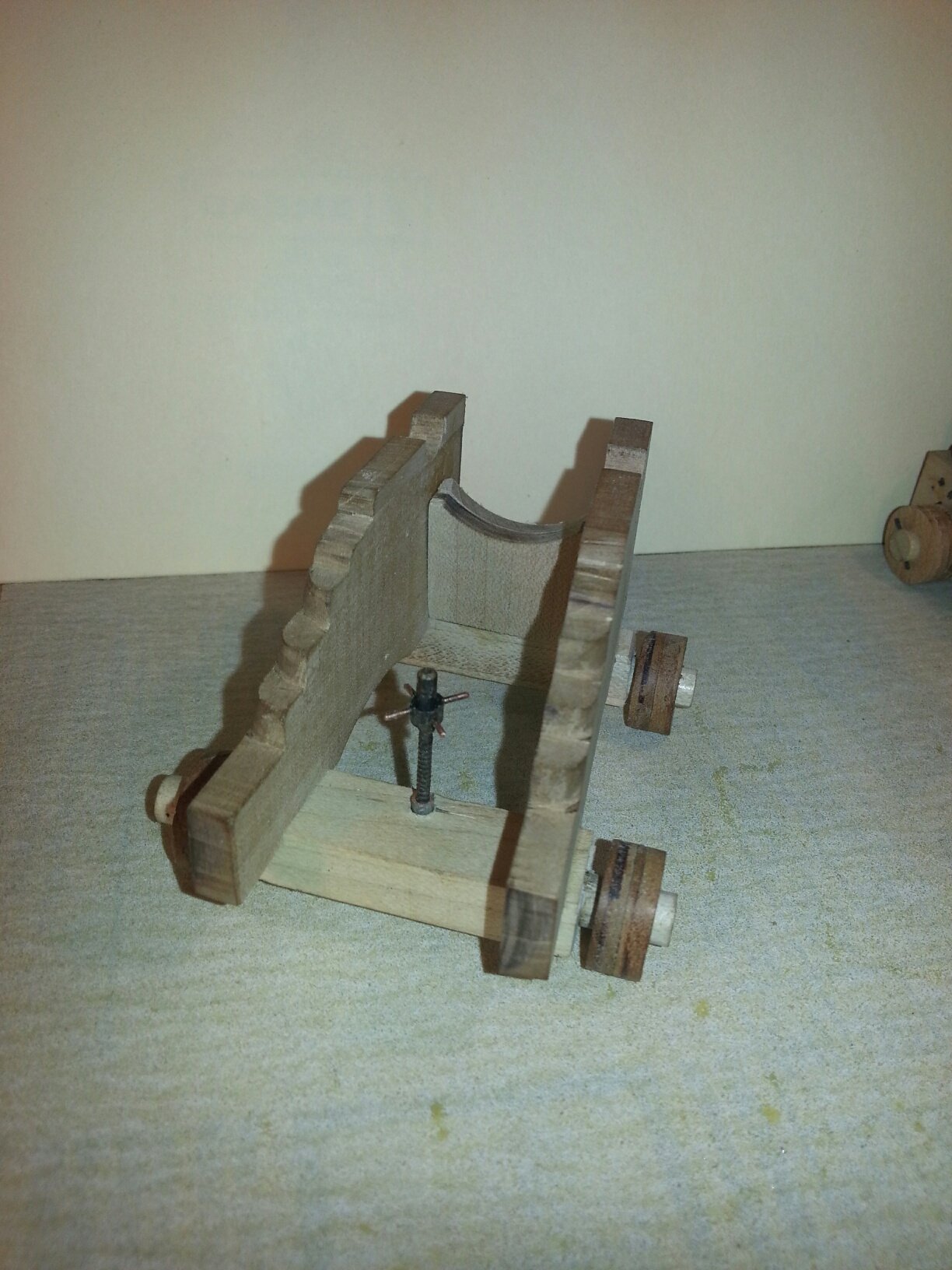
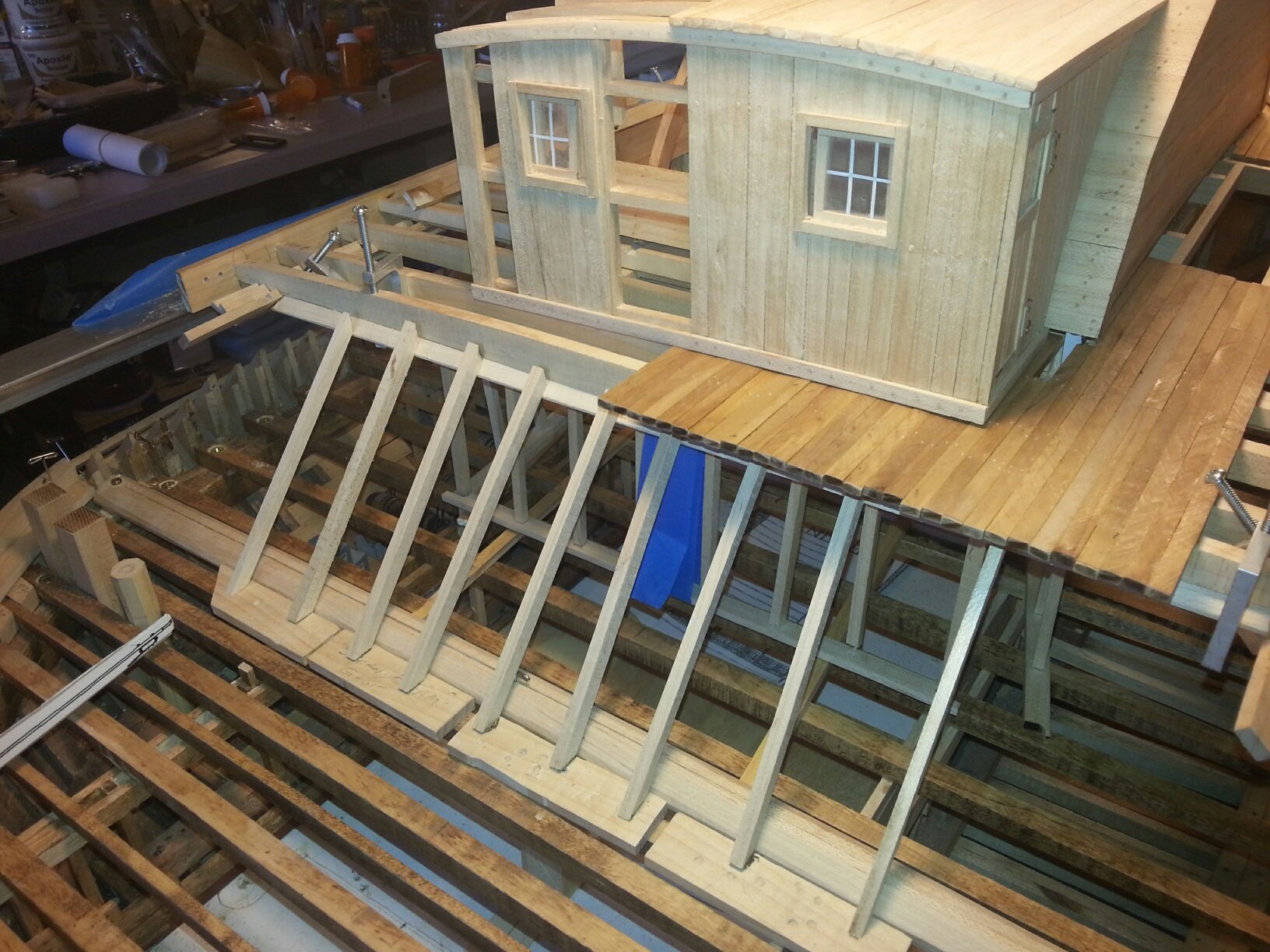
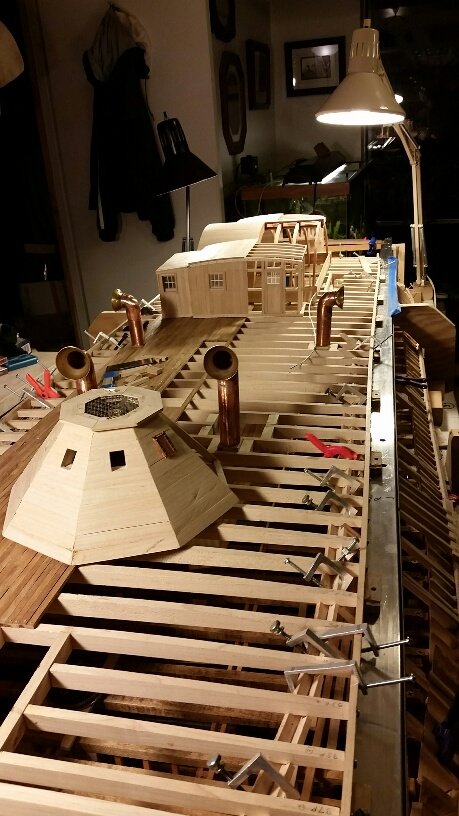
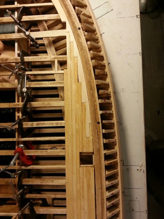
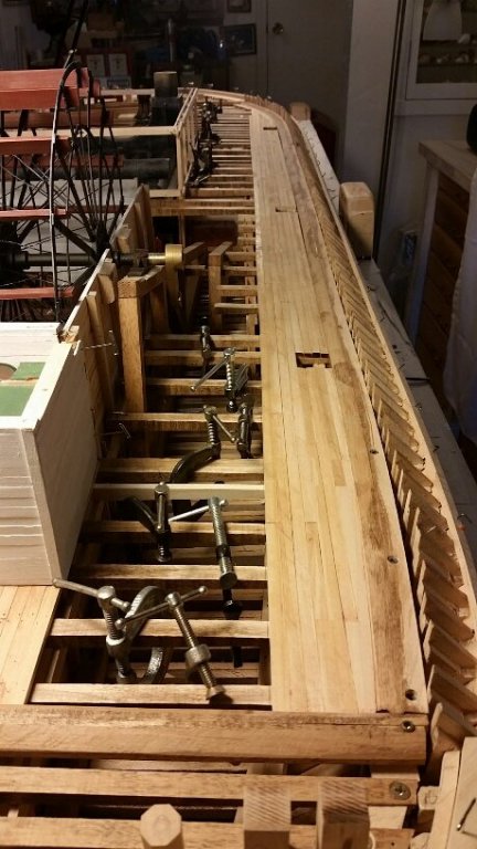
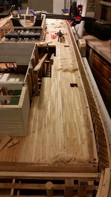
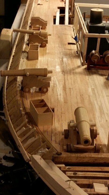
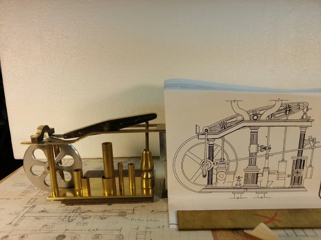
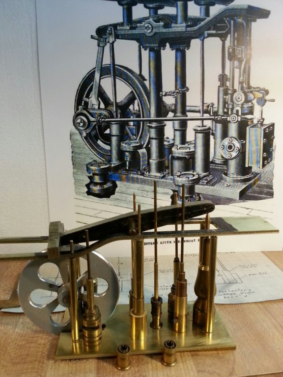
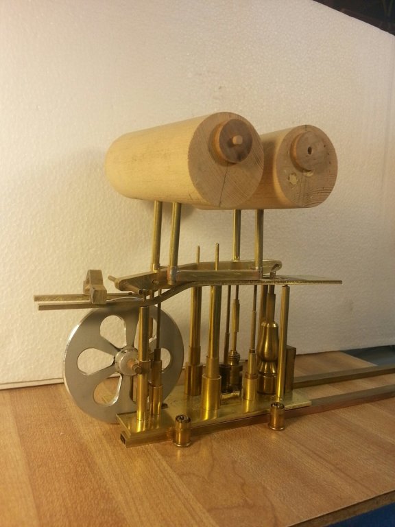
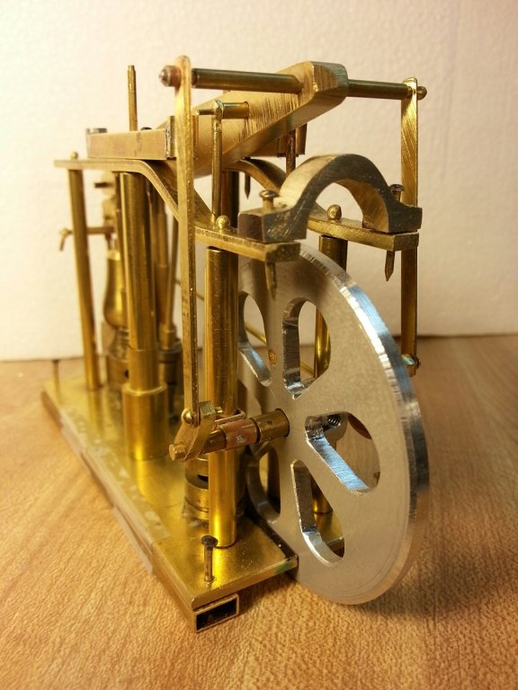
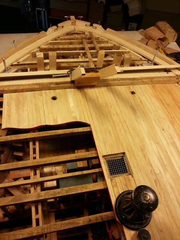
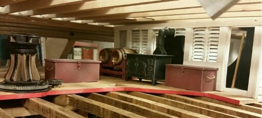
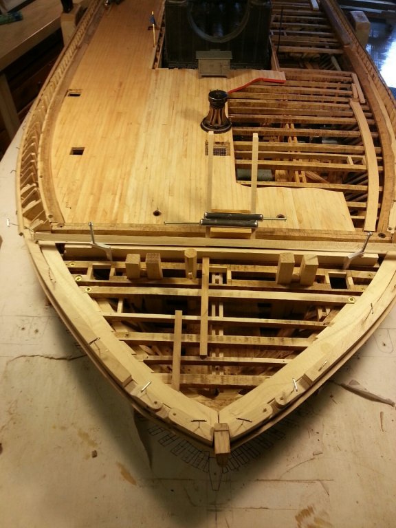
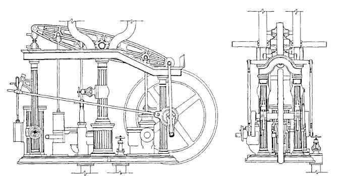
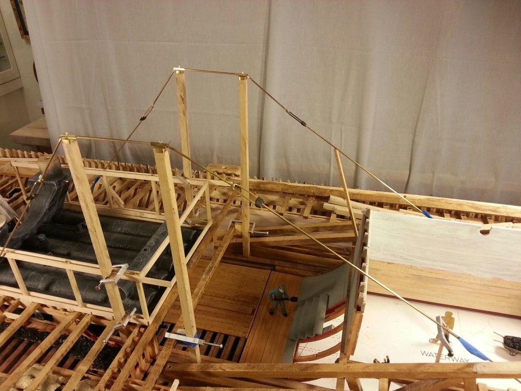
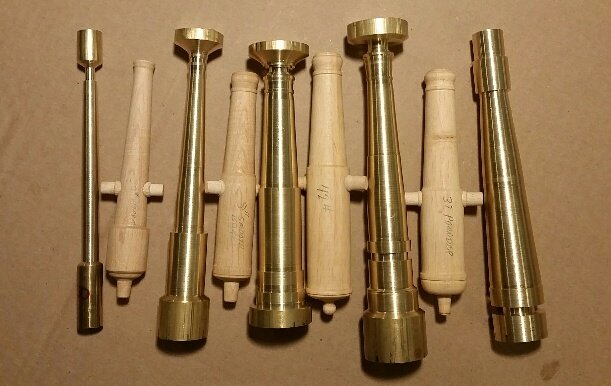
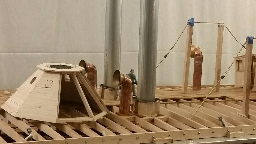
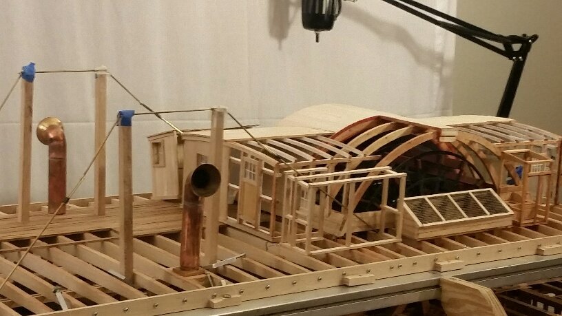
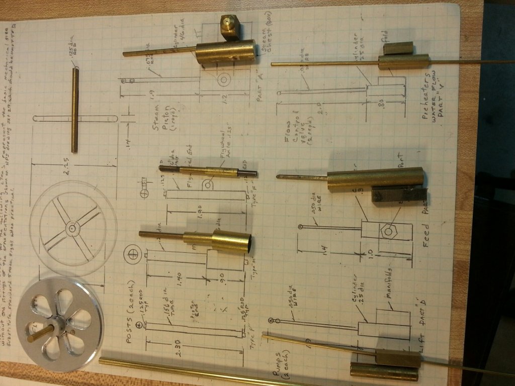
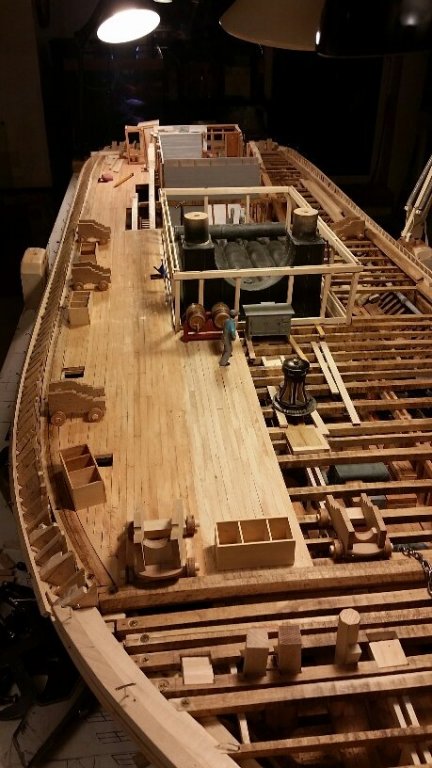
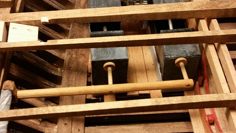
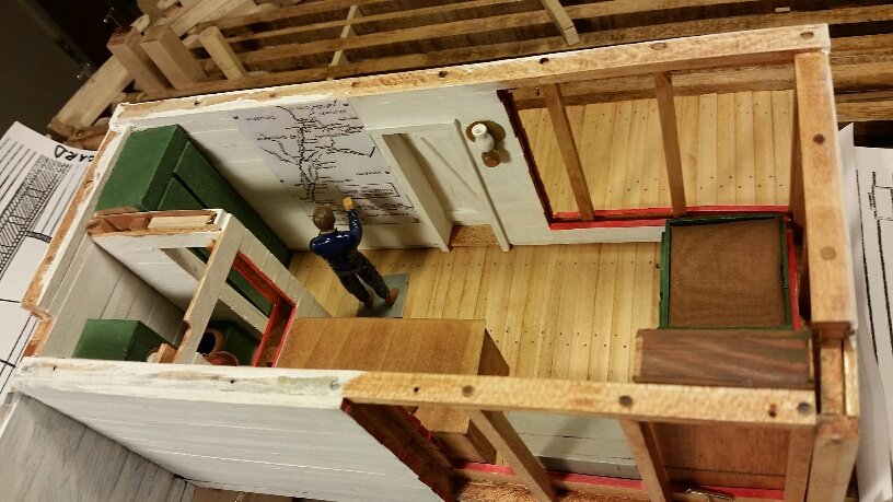
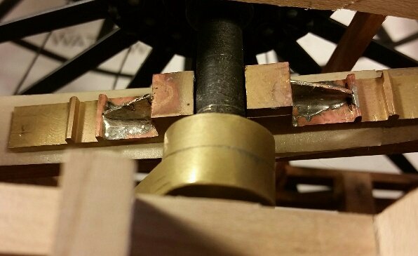
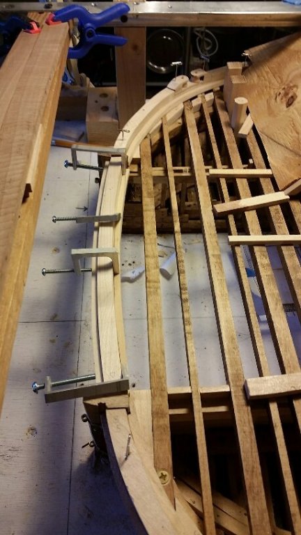
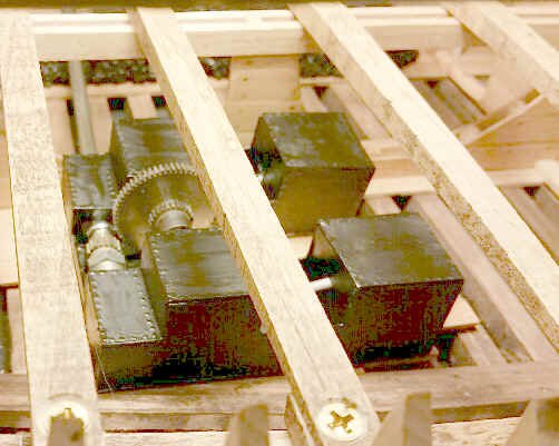
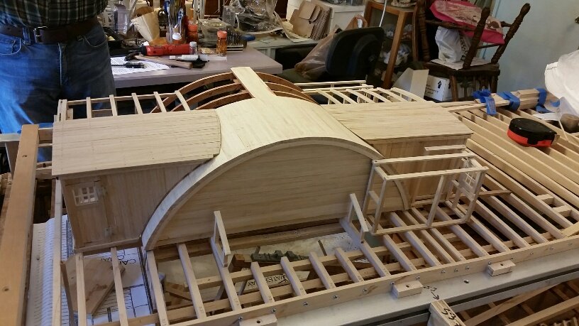
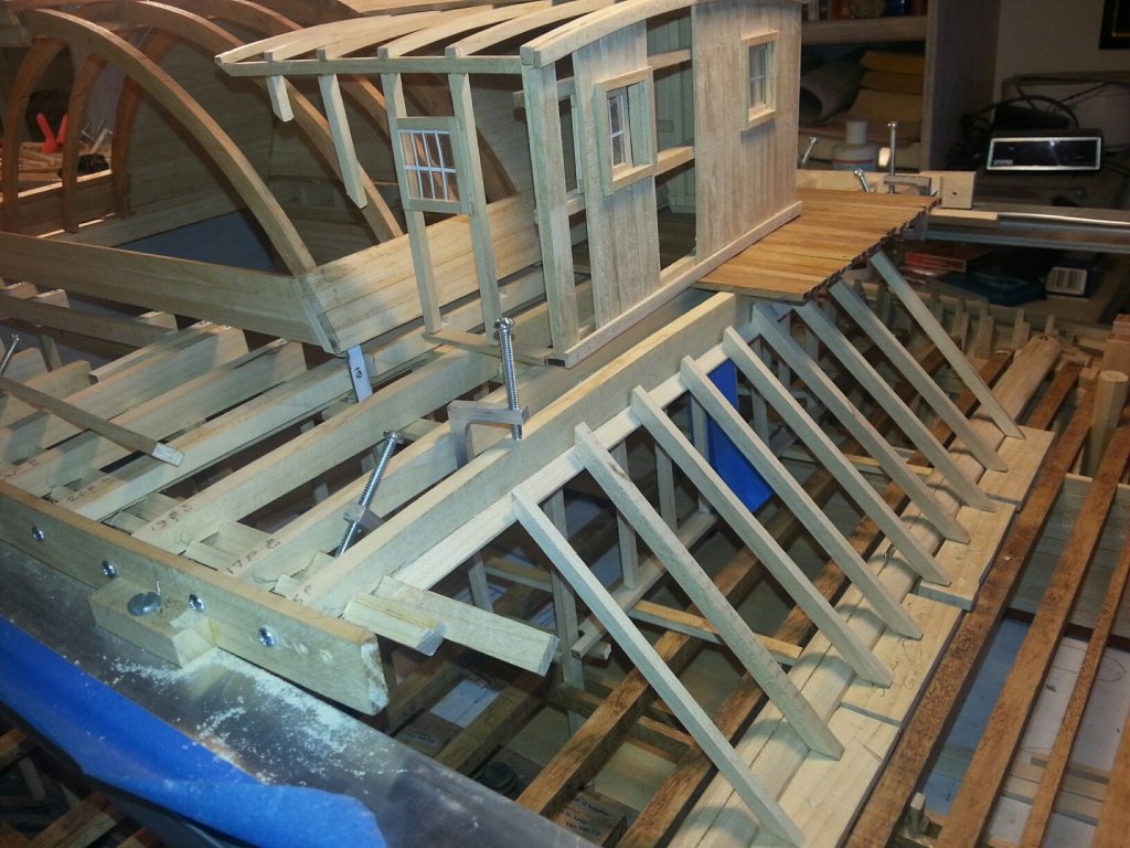
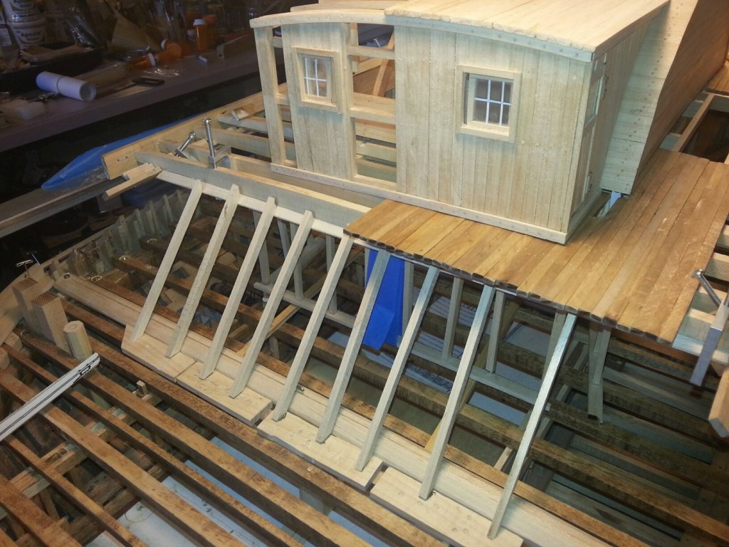
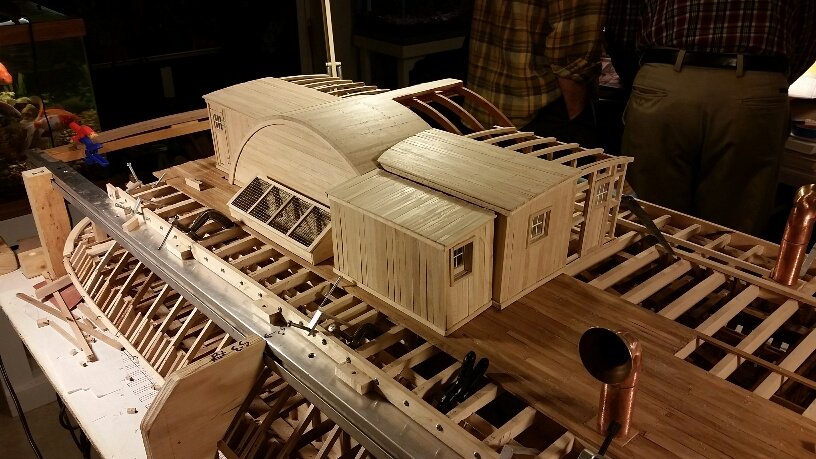
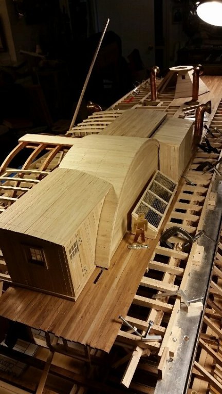
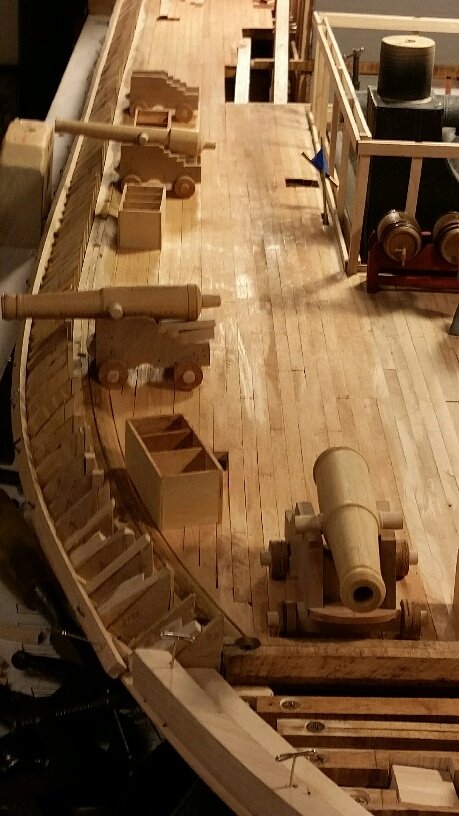
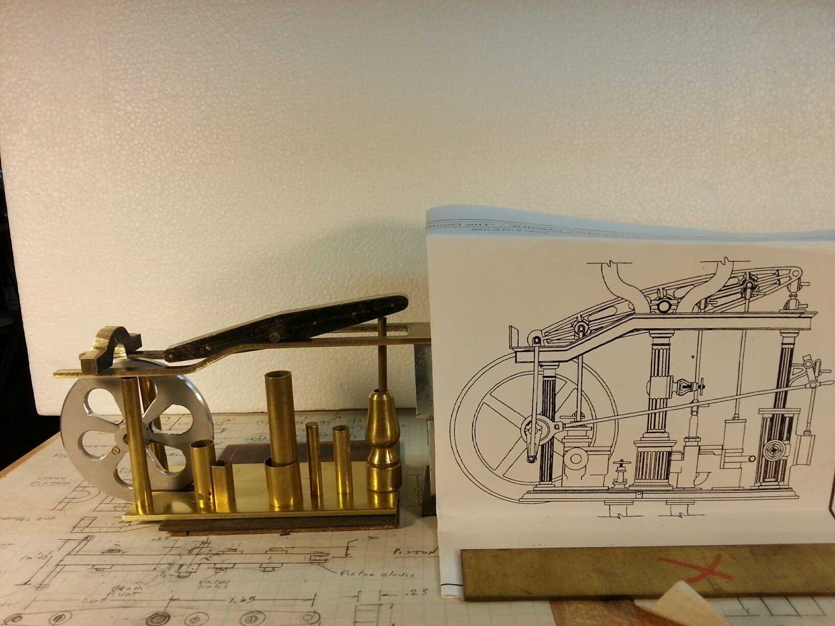
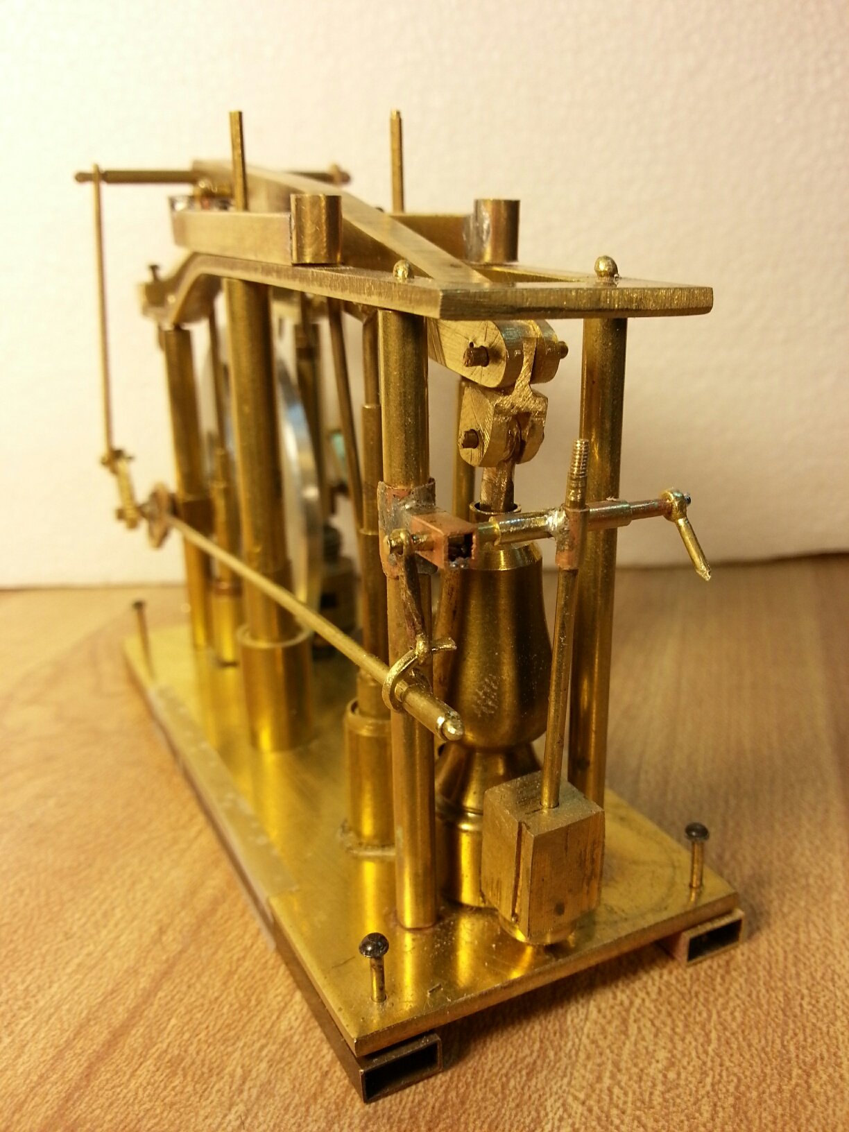
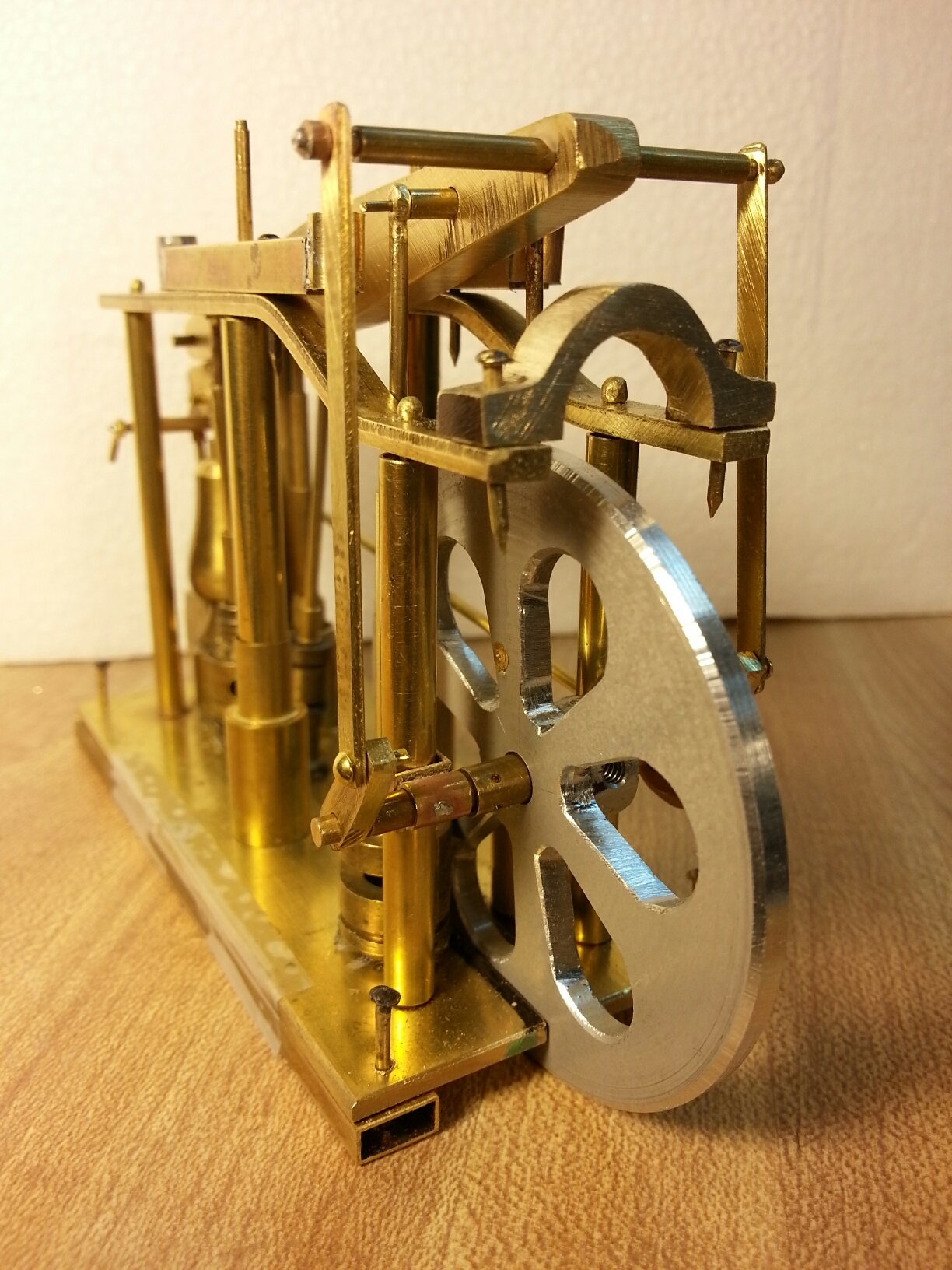
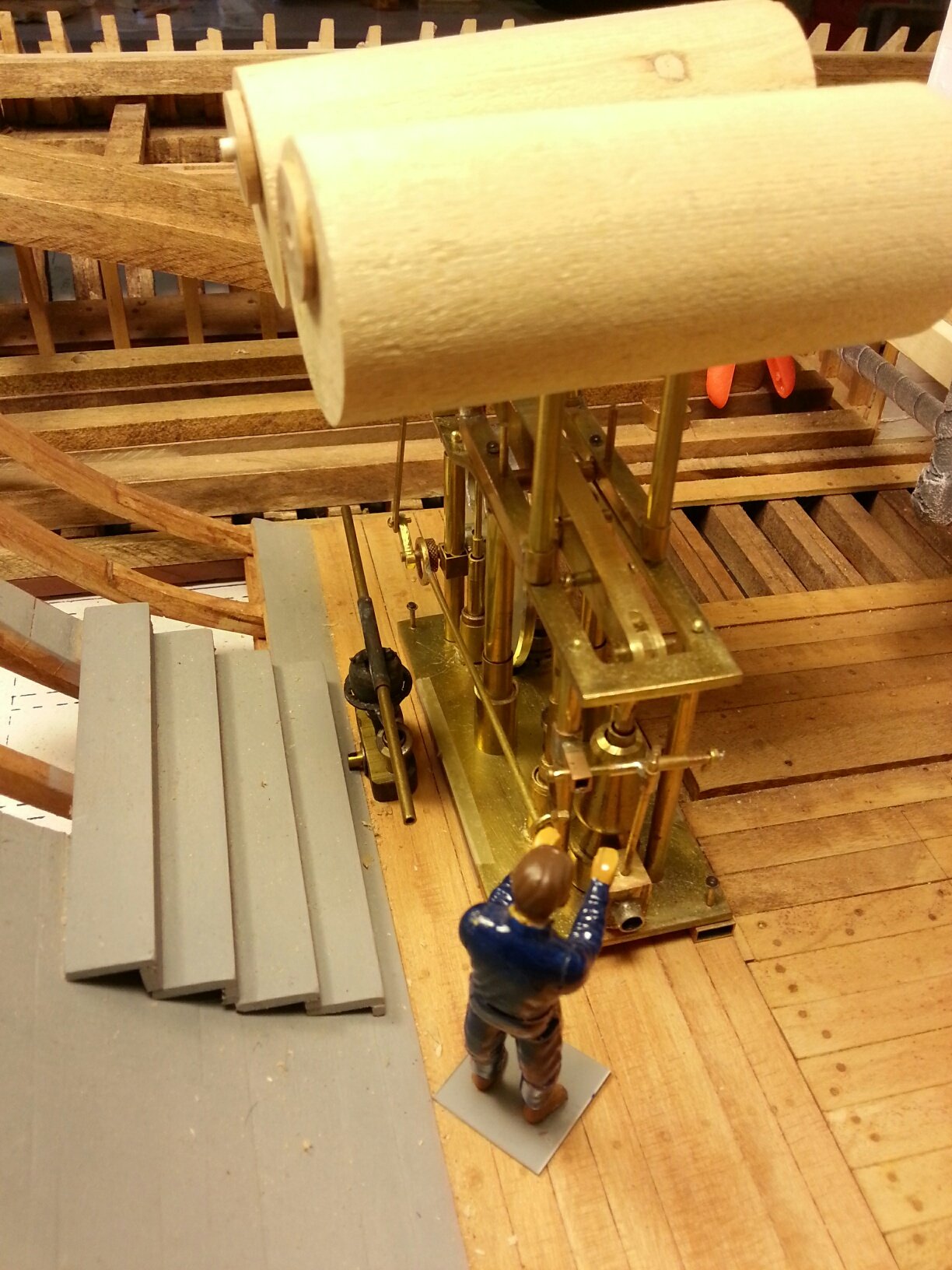
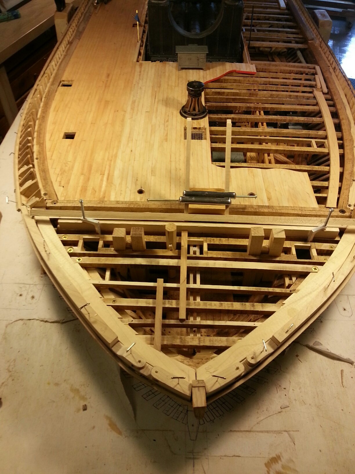
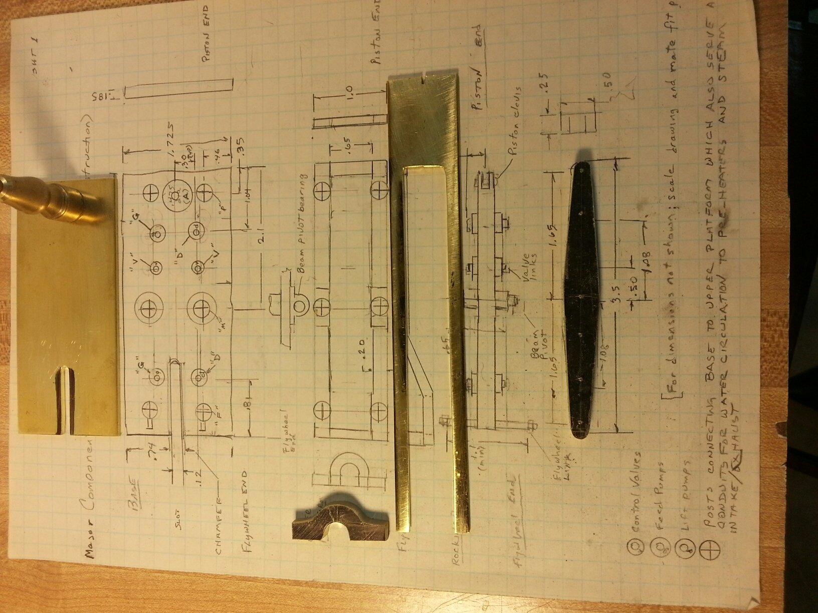
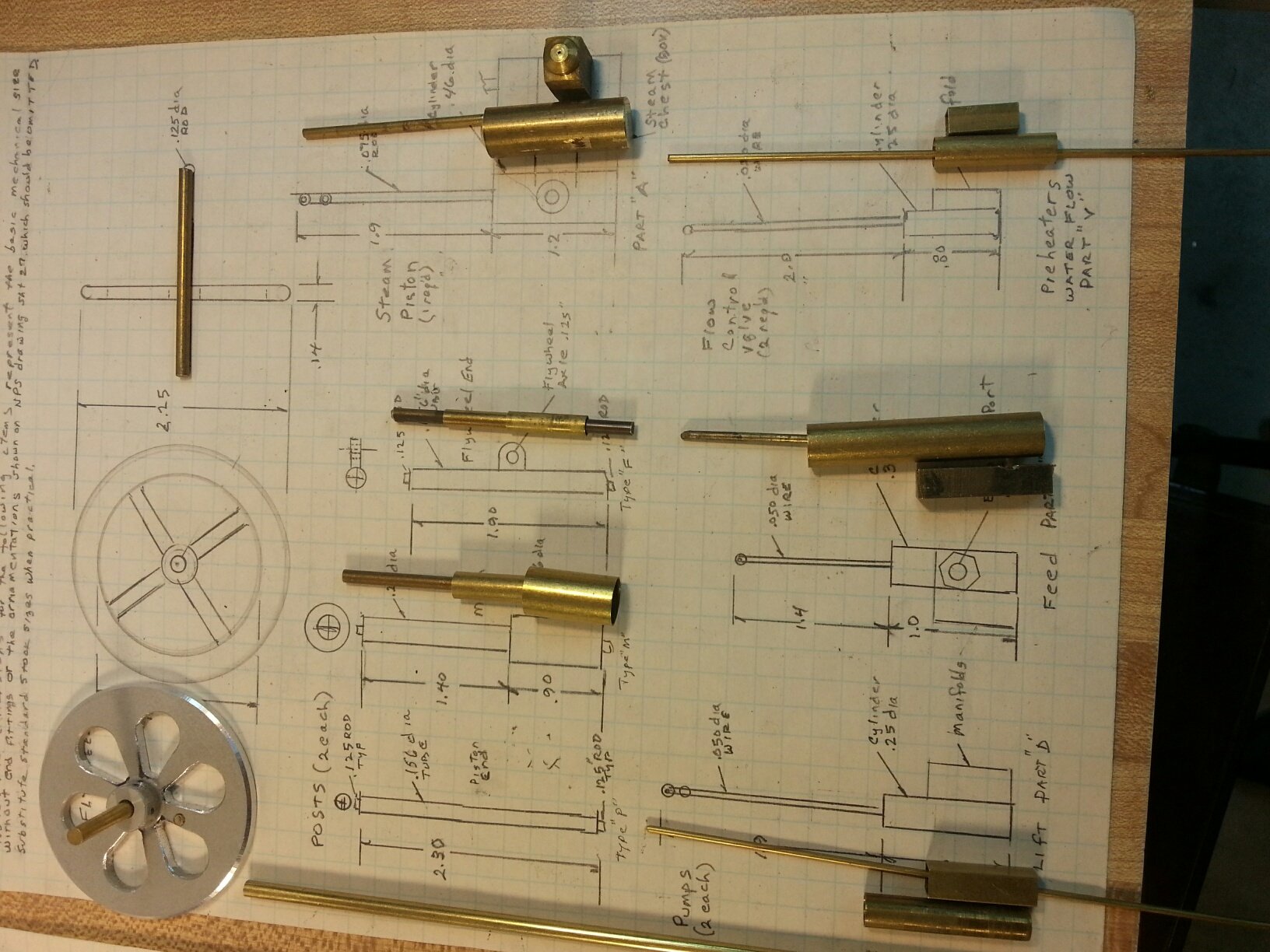
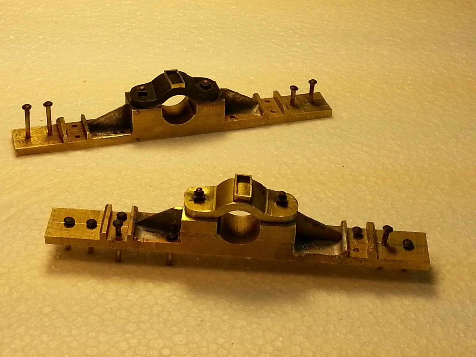
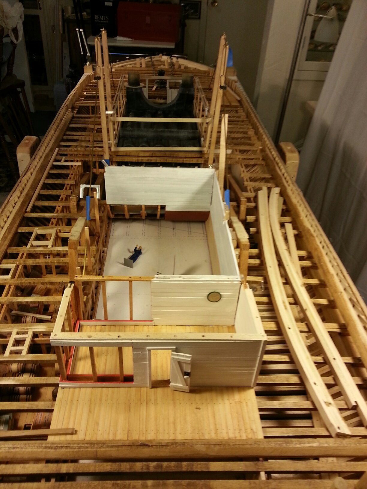
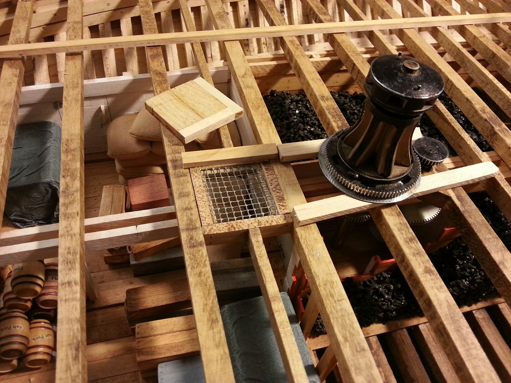
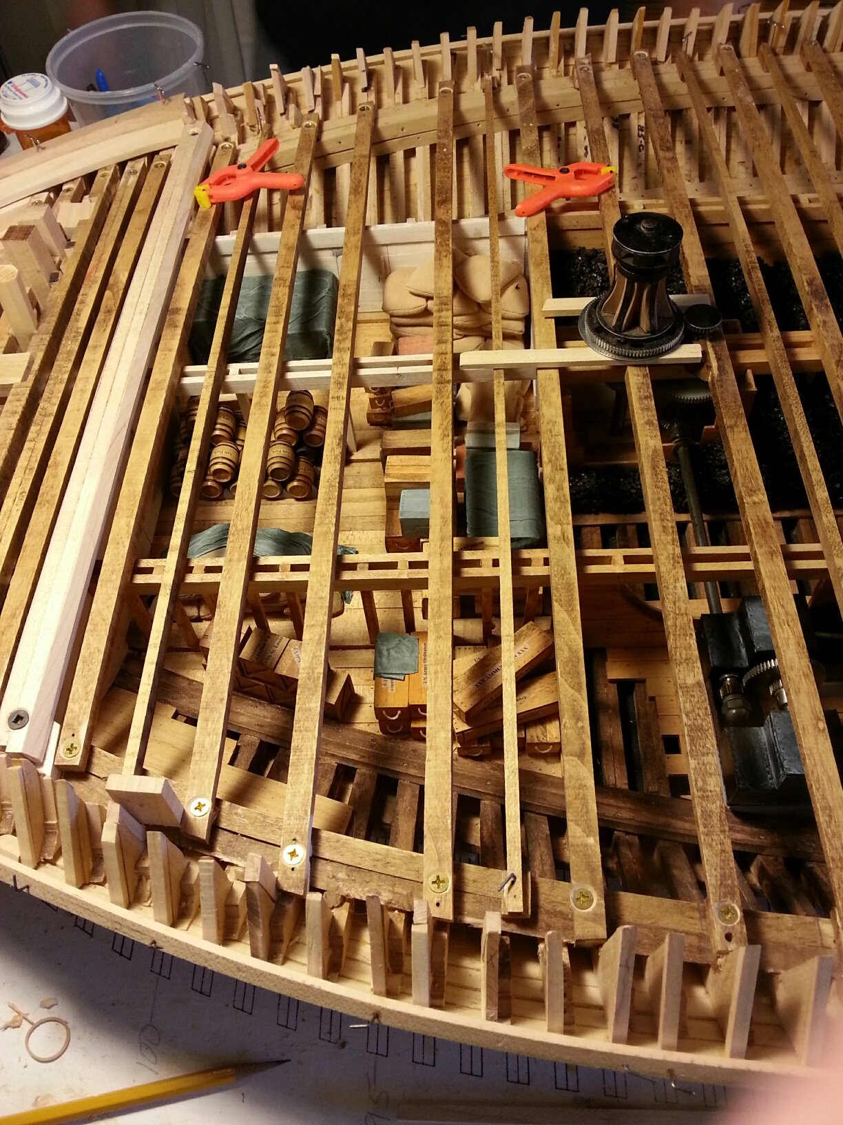
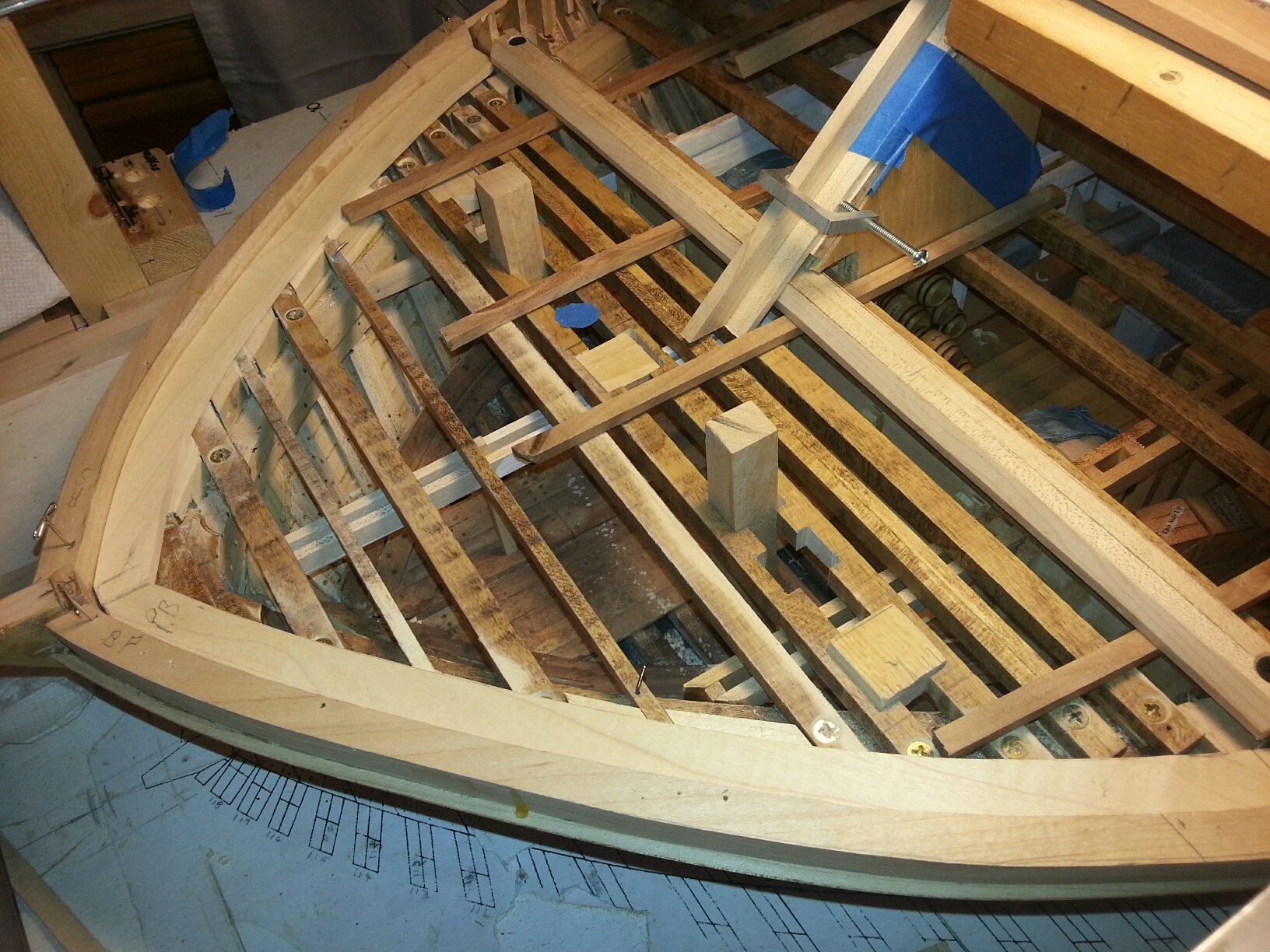
USS St. Louis Ironclad Project update for May 2018: The first 3 photos show Bill's progression from the joggle strip, thru planking for the starboard side of the gun deck to its completion this month. Decking on the port side will be limited to that required to support the the main armament cannon barrels, carriages and load crews. At least one cannon will be displayed having been rolled back from its gun port and in the process of being reloaded. The next series of photos represent progress this month on fabrication of our "Doctor" Auxiliary Steam Engine which serves several functions including maintenance of safe boiler water levels. Since the actual "Doctor" was lost during recovery of the USS Cairo, its City Class sister ship USS St. Louis, our brass engine is based on drawings of a similar, but fancier, engine found in the US National Archive, modified by similar more realistic engines recovered with contemporary Civil War era Western River steamboats. The two large cylindrical units above the "Doctor" engine are heat exchangers which utilize main engine steam exhaust to pre-heat river water before pumping it to the boilers. The remaining steam is them either fed into the wheelhouse to keep the paddlewheel water from freezing in Winter, or is vented to the main stacks. A dry-fit of the "Doctor" and its adjacent manual start-up/bilge pump is shown in the main engine room to help us layout the required piping connections. Our "Doctor" engine model has its own simulated steam cylinder with piston, flywheel, 4 water pumps and control valves, all linked to the "rocking beam" supported by its unique framework. Lastly, several more views of the gundeck near the bow casement provide a good idea of its eventual appearance. johnhoward
.jpg.89067ad1b65c66a335df13737b39169f.jpg)


-
Thanks for the nice comments. Our customer, the Missouri Civil War Museum, requested this large scale model to serve as a focal point for their new display room dedicated to the nautical element of the war in the Mid-West. Part of our objective has been to determine and document how to manage a diverse group for a big project like this which would be very difficult for any single modeler. Although taking much longer than we originally anticipated, we are finally "visioning light at the end of the tunnel." johnhoward
-
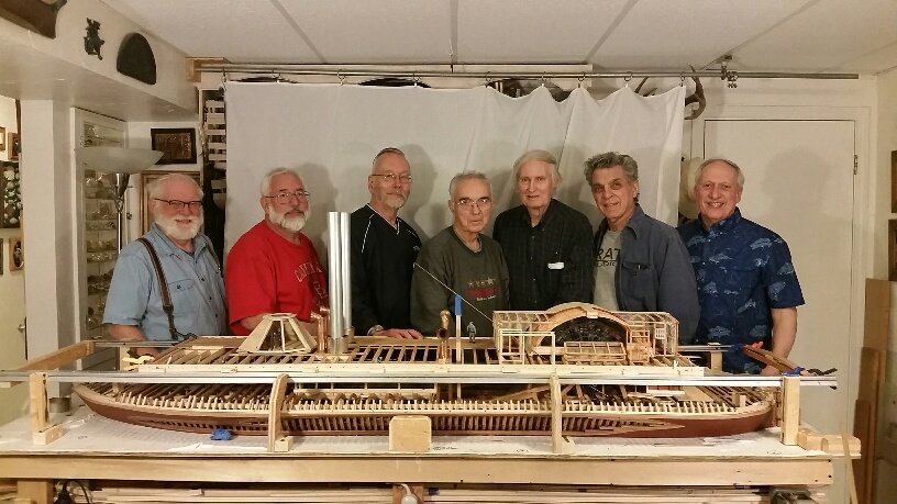
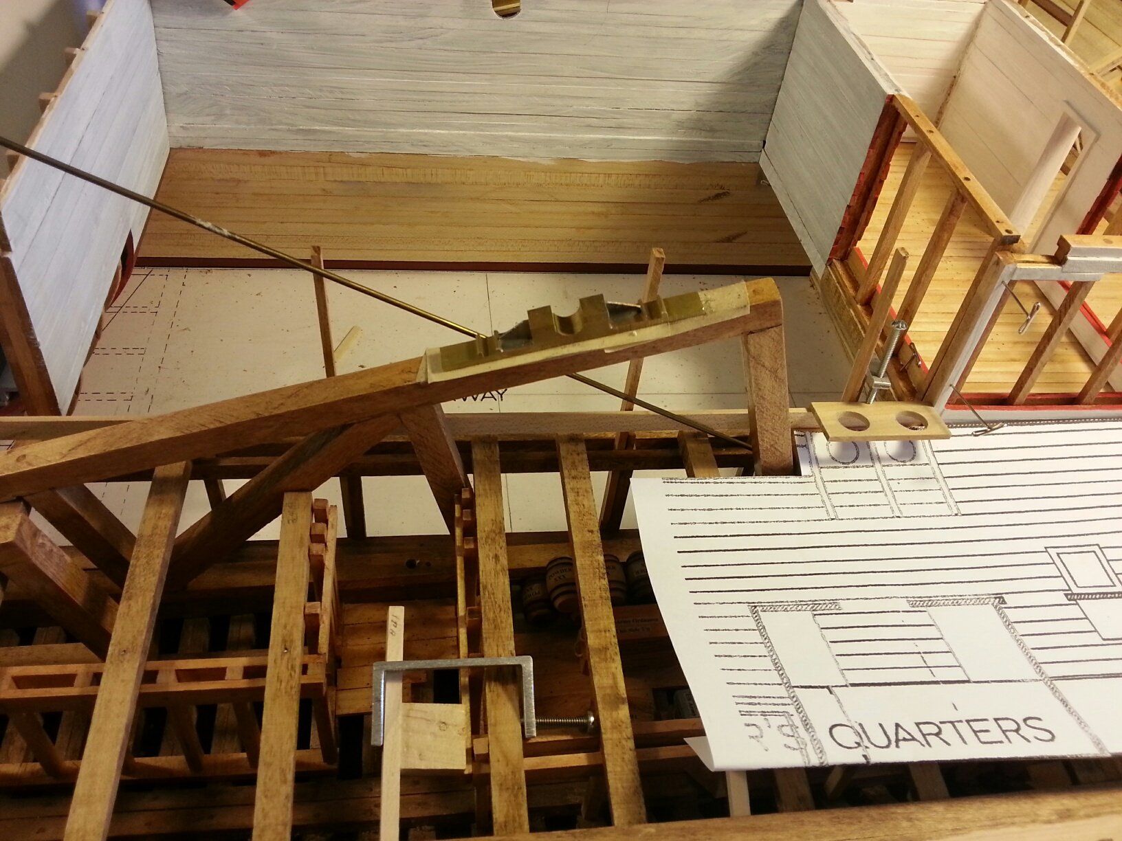
USS St. Louis update for April 2018 Seven of our original 9 Shipcrafter build team gathered to commemorate our 3.5 year milestone on our City Class "USS St. Louis" Ironclad Project and the departure of Scott, third from the left, upon his retirement to Wisconsin. Scott will continue support of the project, remotely in his original research capacity. One of our main accomplishments this month was fabrication and successful dry-fit of the "Hog Chains" which span from the aft end of the wheelhouse on the port & starboard keels to the forward face of the boiler/firebox. The "chains" are actually a combination of cables, solid links and turnbuckles, modeled after those recovered with the USS "Cairo". They fit in a remarkably confined space within the hull structure, penetrate the roofs of the "Hurricane" deck houses, and are supported on four stanchions "footed" on the engine room floor. Another dry-fit of the completed paddlewheel successfully resolved several minor issues. Tom displayed his initial brass machinings for each of the 5 different types of cannon barrels which will make up the 14 cannon carried on the USS St. Louis at the end of September 1862 which our model represents. Completed details of the "Hurricane Deck" were assembled to verify spacing with the new "Hog Chains". Initial sketches have been made for fabrication of our "Doctor" Auxiliary Steam Engine which was lost during the "USS Cairo" recovery. Materials are being gathered for this interesting mechanical contrivance. Bill has continued modeling of the insulated steam distribution and exhaust system. Ten of the 13 wooden Naval cannon carriages were dry-fit at their gundeck stations. The 14th carriage, which will be brass, is for the 12-pdr Boat Howitzer and will be carried on the "Hurricane" deck. johnhoward
_resized.thumb.jpg.a236897b2f823f0c0281d0cccf13e4cf.jpg)


-
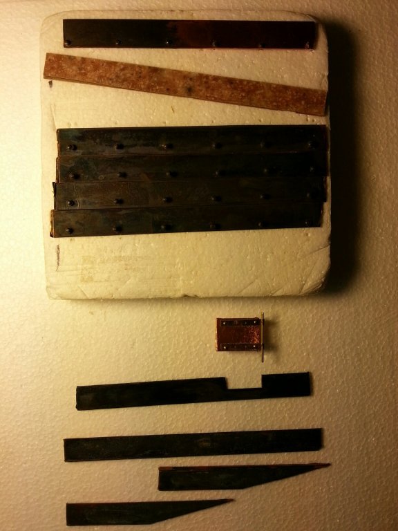
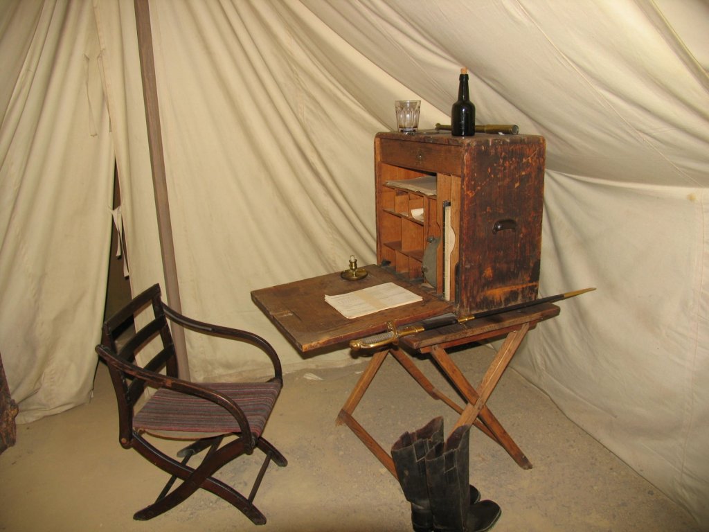
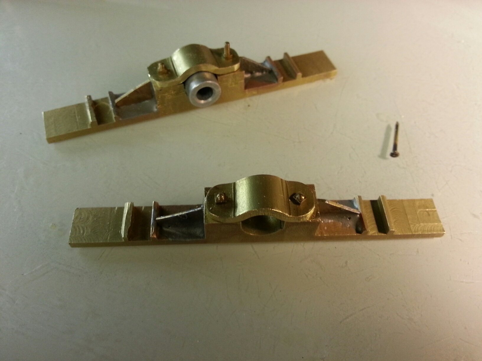
USS St. Louis Ironclad update for March 2018: We began implementation of fabricating armor plating for the pilot house and casements using our previously developed system of covering strips of Formica with .002 thick copper foil tape which was then chemically blackened. The Formica strips are doubled in thickness but off-set about .030" to create rabbets on both sides to resemble the original interlocking armor such that only one side of each plate need be attached to the wood structure with scale 3/4" diameter bolts. The bolts were created from No 18 brass escutcheon pins which were annealed and then headed in an arbor press with a female hex die to form its head and washer. These fasteners are very prominent in views of the casements for the USS Cairo at Vicksburg. The armor for the hull casements was 2.5" thick while that for the pilot house was half that thickness, so two different thicknesses of Formica were utilized. Our research for the junior officer's cabins leads us to believe that they were very likely to have been relatively lightweight canvas and pole enclosures which could be readily disassembled whenever combat was anticipated, rather than enclosures built by carpenters. This is reinforces by the "camp style" display at the USS Cairo Museum at Vicksburg. We also completed finishing the wheelhouse and performing a successful dry-fit of the completed paddlewheel. One interesting result of this dry-fit was that our Pittman arms, as built, could not be connected to both the paddlewheel axle bellcrank and the engine piston clevis at the same time, because they are not perpendicular to each other. This would require mono-ball bearings in each end of the Pittman arm to accommodate the 3-degree angle. Later research determined that such mono-ball bearings were in actual use by 1840 mills and factories. We will simply add chamfers to the Pittman arms to make it fit. Bill started fabrication of the insulated steam-pipe delivery system and planking the starboard side of the gun deck as we intensify our effort to close off this area. johnhoward . Cairo,Bow.bmp
.jpg.1c52eb7558f2e6727c5b90803048f288.jpg)

.thumb.jpg.a933eb8ebb57e4a6a75b8f09d379ddde.jpg)


-
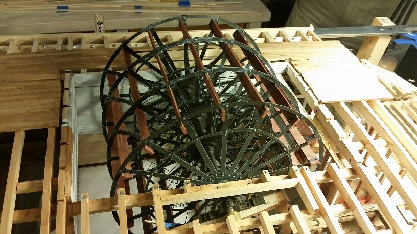
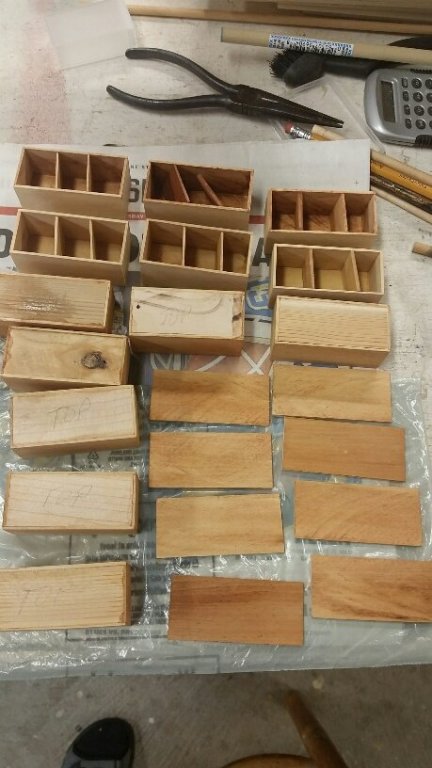
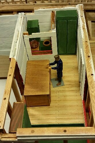
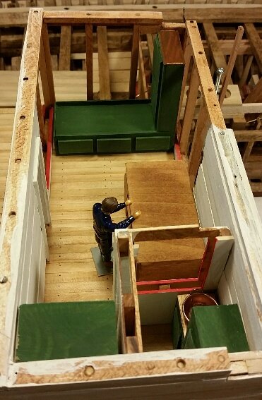
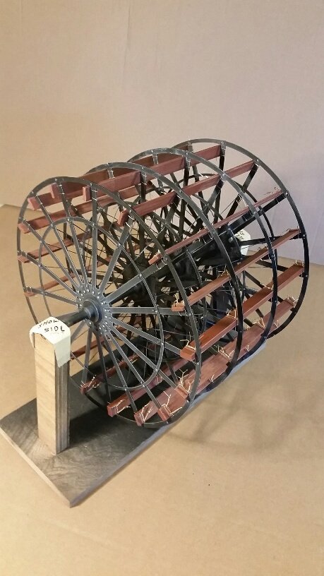
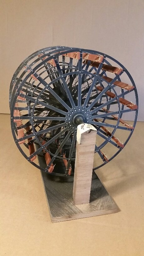
In an attempt to bring this log up to date I will be adding progress photos for the USS St. Louis month by month since February 2018. This is the remainder of our activity for February which primarily consisted of completion of our brass paddlewheel assembly, attachment of its paddle-boards, its axle saddle machining, the captain's quarters, cannon ammunition cases, and a few structural additions. johnhoward


-
That's great Gerhard. I have also neglected to keep my USS St. Louis log up to date for about 6 months but have made continuous progress and will be posting it soon. Johnhoward
-
Gerhard, I'm very sorry for your personal problems but VERY glad you are OK . johnhoward
-
A few more recent photos related to my previous posting. johnhoward


-
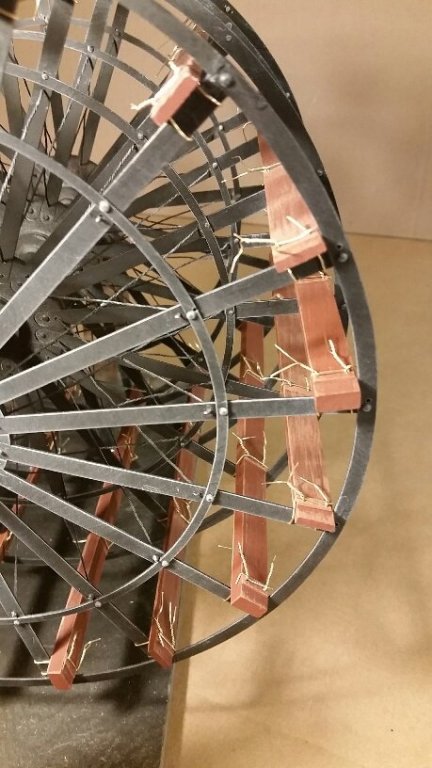
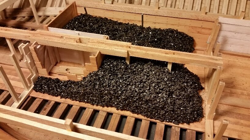
We have again temporarily removed the Hurricane deck and are cleaning up numerous details on the gun deck such as the stern bulwark rail, the Captain's Quarters, coal bunker door with sacked coal, the paddlewhee, axle pillow-block supports and framing of gun deck access hatches in preparation for gun deck planking and eventual reinstallation of the Hurricane Deck. We have also started installation of the 17 paddleboards (Buckets) on the paddlewheel and fabrication of the 2 main steam engines which will be shown in future photos. johnhoward

-
Thanks Eric, We really enjoyed your visit. johnhoward
-
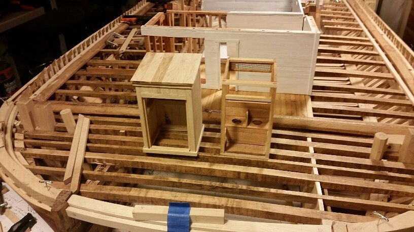
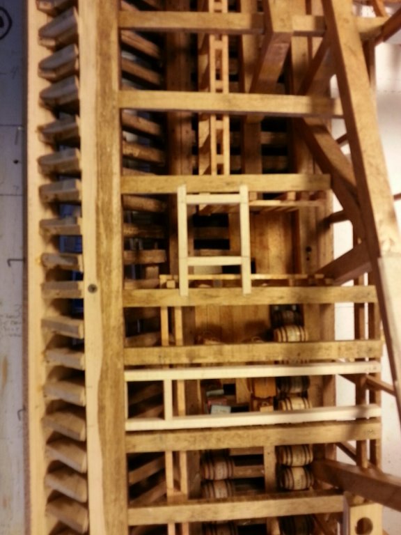
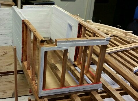
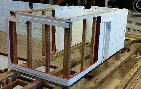
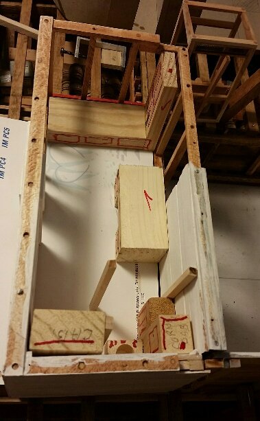
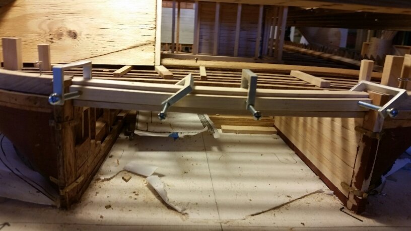
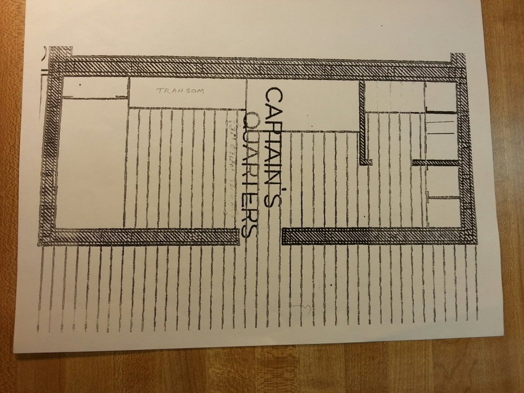
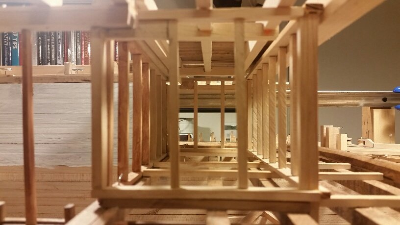
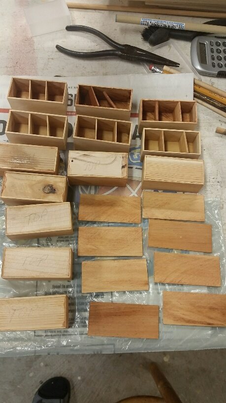
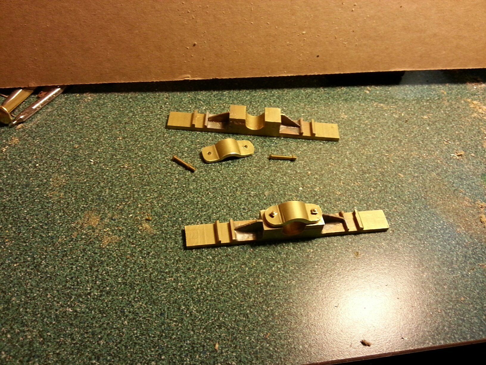
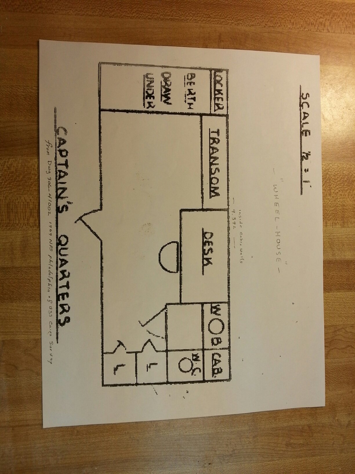
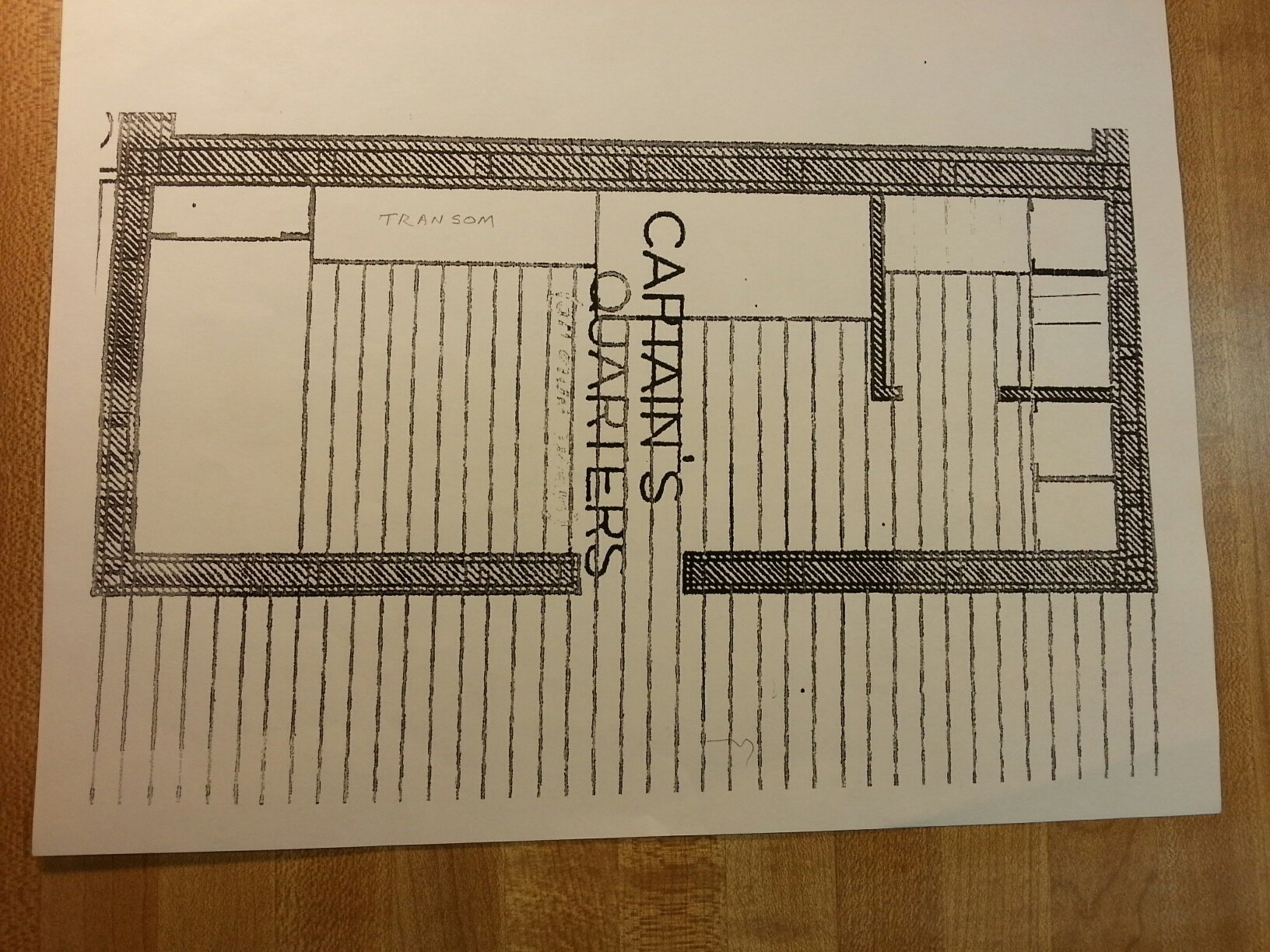
Attached are sections of the Philadelphia National Park Service 1968 drawing of the Union Gunboat "Cairo" depicting the "Captain's Quarters" and a port side photo of the structural framing for our model cabin on the "Cairo" sister ship "USS St. Louis". This cabin is located on the gun deck and shares a wall with {Paddle} wheelhouse (on the left) and would be about 5-feet from the stern casement (on the right) in this photo. We are planning to include the cabin interior furnishings on our model but so far haven't been able to determine what the area labeled "TRANSOM" represents. It seems unlikely that it is a typical architectural type window transom normally located above doors for ventilation since the paddlewheel was located immediately on the other side of the cabin wall containing the transom. It also doesn't appear to be related to a nautical type transom which forms the stern of a boat. Its plan full size 65" x 17" could possibly indicate that it was a closet or large chest but we haven't found any such connection to the word "TRANSOM". Any ideas on this subject would be greatly appreciated. johnhoward

-
Roger, We totally agree with you on these options and have made a concerted effort to verify contemporary technological accuracy for everything we include on the model and document any physical changes we have made to the published plans and drawings of sister ship "USS Cairo", which in many cases we realize were only reconstructions themselves, and the National Park Service's Historical Structural Report (HSR) which summarized the "Cairo" recovery findings. We have selected the October 1862 version of the "USS St. Louis" for our model configuration, primarily to establish its main armament, but this is also the point in time at which it was renamed the "USS Baron DeKalb" and its control transferred from Federal US Army to US Navy Command, since our museum is located at a US Army facility. Our most reliable independent resources for the accuracy of "City Class" ironclads are their few existing contemporary photographs but even these have been obviously retouched and mis-identified. For all practical purposes only the metal remains and a few identifiable artifacts of the "USS Cairo" reconstruction at Vicksburg have been of much technical value. We had hoped to find something to differentiate between the "USS St. Louis" and her 6 sister ships but so far the only possibility is the highly contentious "Masonic Symbol" depicted on the bracing between the smokestacks in some highly retouched photographs, and supposed news reports that she was referred to as "The "Masonic Ironclad" which we have been unable to verify. Our hope is that opening discussions on this Forum as to how these types of ironclads operated will uncover new avenues for us to research further which appears to have been fruitful regarding coal sacks. johnhoward
-
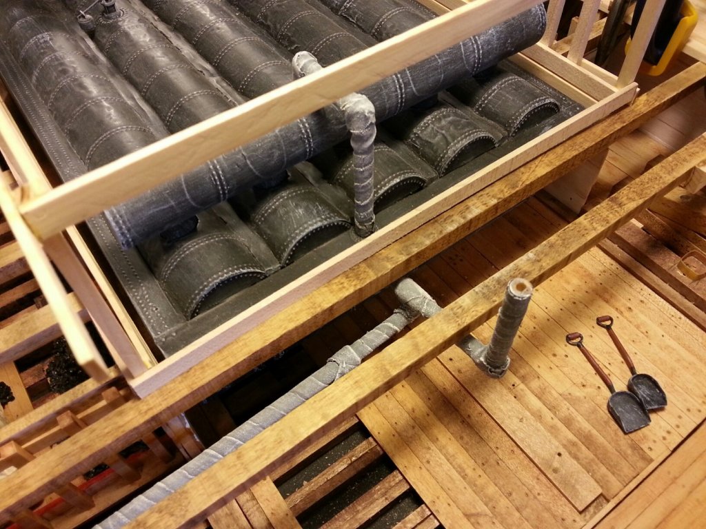
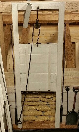
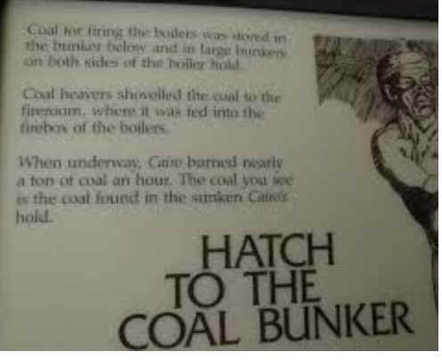
One last message for tonight, I long ago found these two illustrations which explain the exhibits for the USS Cairo, (sister ship of our USS St. Louis) currently on display at the NPS Cairo museum in Vicksburg, Mississippi. Putting this together with the recent suggestion of sacked coal, I took another look at this drawing. In the background showing the open coal bunker door, it clearly looks like stacks of coal filled sacks rather than just a poor drawing of bulk coal as I had previously assumed. In the foreground is a very good representation of the firebox and open door along with a shovel full of small "Steamboat-sized" coat that I would expect. While not a proof of anything it looks like the museum believes coal bunker was loaded with sacks of bricket sized coal, which makes a lot of sense to me as it solves a number of problems with filling the bunkers.. johnhoward
.jpg.9d5507a2e6918a4c1643d851cc5b434e.jpg)
-
Eric, thanks for the suggestion; your nice model construction appears to be very similar to ours. The fireroom/fireboxes for City Class ironclads were directly on the keel flooring about 4-feet below the waterline to protect them from enemy gun-fire. Our problem is getting ash and slag up about 5-feet onto the gun deck.. Once there, it would be possible to dump it overboard via a trough and thru a side casement gun port or possibly one of the deck scuppers. Our ironclad model is being built in the basement of our Gateway Model Shipcrafter's club president in Ballwin, Missouri and we meet monthly and work on it there 2 or 3 days a week. Visitors are always welcome and our contact information is available on the Model Club listings of this NRG Forum, so you can make special arrangements for a visit by phone or E-mail. I also currently E-mail our monthly meeting notices with model progress reports & photographs to a number of "guests" and other model club secretaries throughout the country, if so desired. Hopefully our model will soon(?) be on real public display at the Missouri Civil War Museum (MCWM) at Jefferson Barracks in downtown St. Louis, whenever completed. johnhoward
-
Thanks John, a canvas chute makes a lot of sense, at least when nearly vertical thru a scuttle. johnhoward
-
Roger & Pat, Thanks for the additional insight. This will help focus our further research significantly. johnhoward
-
Pat & Roger, Thanks for your interesting suggestions, I'll try to cover them all The distance from floor ceiling boards to overhead beam was 5-feet. I suppose a rotating chute would be possible for spreading the coal and work better than wheelbarrows and shovels. I know people were shorter in the 1860's but this is ridiculous. Do you have any ideas on how high they would try to pile coal in a 5-foot high bunker? or what the normal coal capacity would be for such a 20-foot square bunker? These ironclads burned about 1-ton of coal per hour when steaming and I suspect they coaled up every chance they got on the river banks & from lighters but maybe never really filled the bunkers for a long distance mission. We haven't found any evidence of separate compartments in the main bunker except for an enclosure around the capstan's below deck gearing which is near the single scuttle. However, there are two side bunkers adjacent to the fireroom which I assume were unloaded equally to maintain balance. You bring up another issue on ash & slag removal from the fireroom which must have been equally troublesome, especially to eject it overboard or was it just temporarily stored in an empty coal bunker. We have two side by side doors from the fireroom to the main coal bunker, one on each side of the keel, and one at the forward end of each of the side bunkers. Would it make any sense to load the coal bunkers thru the larger fireroom doors via wheelbarrows or carts rather than chutes thru the smaller scuttles? The cloth bag idea seems promising and would appear to be a lot better than loose coal and dust on the gun deck. Could the coal have been left in the bags and more easily stacked in the bunkers until brought to the fireroom for stoking the furnaces? Do you think the coal was loaded as available bulk material or readily burnable "steamboat size" brickets? johnhoward
-
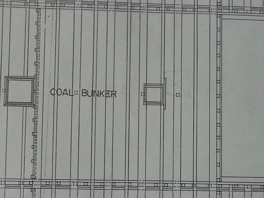
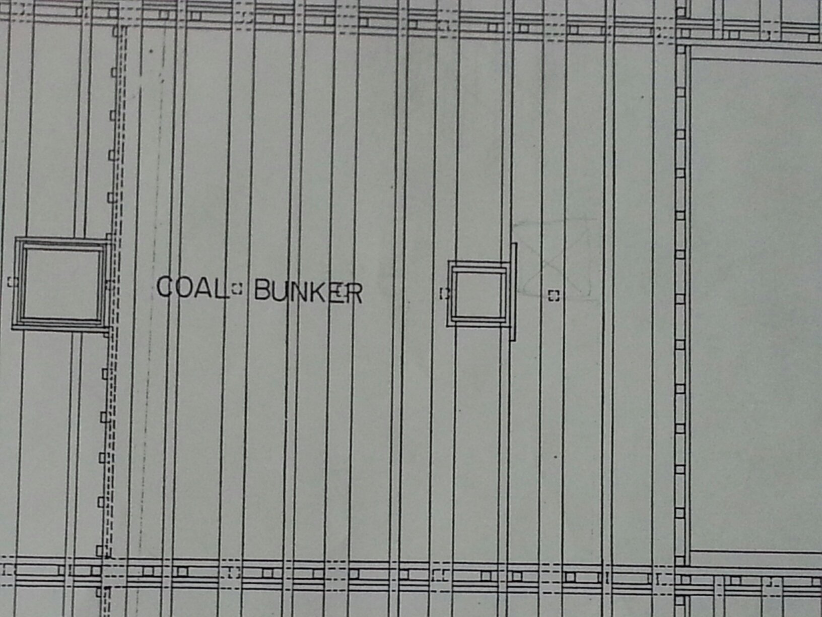
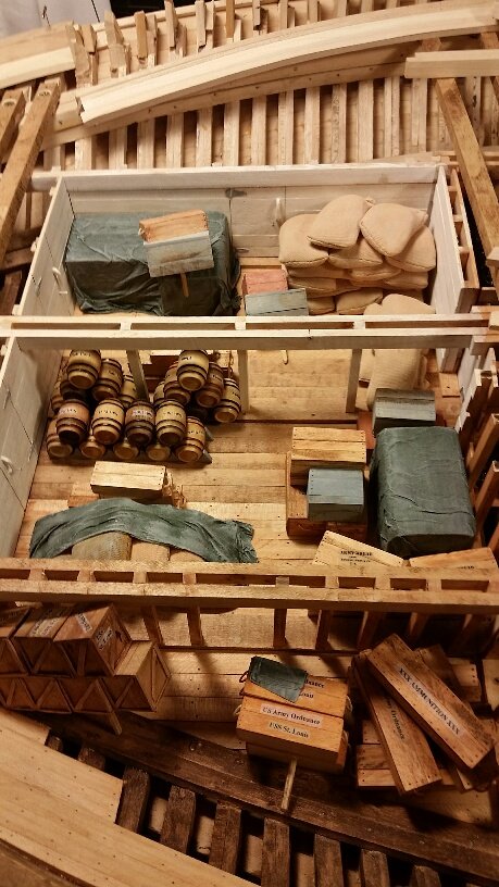
Thanks for all of the "Likes" we have received on this discussion. One additional issue we have been pondering over on the "coaling" procedure is "How did they manage to fill (respread the coal) the 20-foot x 20-foot x 5-foot high main coal bunker shown in our last photo and the attached drawings from the single 2-foot square scuttle at the center of the bunker, assuming they managed to get the coal to the scuttle in the first place?" It would appear that they wouldn't be able to achieve a very high depth of coal with wheelbarrows and shovels without significantly more scuttles. johnhoward
.thumb.jpg.ba9f797e2e093a5413f593bb48f23049.jpg)

-
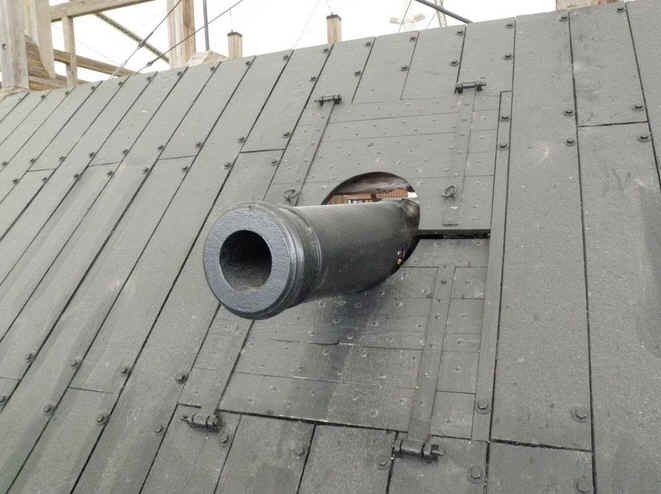
Eric, Some interesting comments. You're probably correct about the low rate of fire. I don't think these ironclads often, if ever, intentionally engaged in broadsides with other vessels but were used mostly for bombardment of inland targets. The bow armor was 25-inches thick combination of solid wood and 2.5-inches thick iron plates. Their limited side casement armor only covered their mid-ship boiler and engine sections. All of their gun port lids were only 2.5" thick oak with no armor cladding at all. Most of their heaviest cannon were located in the bow casement gunports which had a little more room to retract their guns for reloading, however I've never seen any detailed reports on their battle practices. As for deck wear, I'm sure you're right, but these ironclads were originally built as an emergency stop-gap and weren't expected to last very long anyway. I think they were much more successful than expected, largely because the Confederate Navy didn't have any counterpart on the rivers at that time. I do agree they must have used a chute for coaling especially if the coaling facility was compatible. The main coal bunker scuttle was on the boat centerline, about 25-feet from the side casement and nearest gun port which had a 2-foot high sill. A chute this long wouldn't have much of an angle decline to help feed the coal along. The single scuttle for each of side coal bunkers is closer to a gunport but is against the wall behind the cannon. I've read somewhere that coaling was sometimes done thru a gunport but then transported further with buckets, but am not sure this was the standard practice or just in an emergency. It would probably be easier to just use a chute thru the gunport to dump the coal onto the gundeck and then shovel it thru the scuttle into the side bunkers. johnhoward
-
Mark, No, as I mentioned in my initial message, the City Class ironclads were unarmored on all deck surfaces and in fact the Hurricane deck was only covered by relatively thin planking which provided scant protection from plunging fire such as occurred at the cliffs of Vicksburg. However, stout 8.5" wide deck beams, spaced about 26" apart supported the full Hurricane deck planking between the bow and stern casements which would limit the size of any opening. We also thought it probable that portions of the deck planking were removed by the crew carpenters for loading provisions but also probable that, once done, it would be made into another reusable scuttle and not simply replanked. Another possibility was that larger permanent scuttles were provided inside of the aft deck houses but no evidence of this has been found. The shot and powder rooms were between the paddlewheel & officer's quarters and accessible thru small scuttles in the gun deck and "passing rooms" but not very close to a gunport. The USS St. Louis log (diary) does mention some ship remodeling activity by the crew carpenters to add wood protective barriers for machinery but not for additional access. johnhoward
-
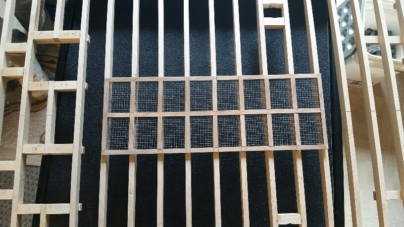
Eric, Thanks, You are correct that the 8 port and starboard cannons couldn't be retracted very far but the carriages could be rotated 90-degrees to the side as they normally were for reloading, since the lateral spacing between guns was fairly generous. Regarding the iron grate, I'm sure it could be removed, however that only gives you access to the top of the boilers, inside a room which also contains the longitudinal steam exhaust pipes from the two main engines to the funnels and other mechanical equipment such as pressure relief valves, and still no apparent exits to the gun deck. These are the kinds of things that building our large scale (1:24) detailed model have been revealing to us. johnhoward
-
Mark, Thanks for your thoughts. The ironclads had only one 2-foot square scuttle on the gun deck over each of the 3 coal bins, and although they were not very close to a gun port , I agree this makes the most sense for coaling and manpower was not an issue. We have been assuming that they burned what was called "Steamboat" coal in the mid-1800's, which was about the size of today's Barbecue brickets, but not sure if it was pre-sized before loading. The "City Class" Ironclads were built in 6-months and commissioned in about a year. They were originally under Army command and had trouble finding (drafting) hearty enough crews to man them until transferring to the Navy in late 1862. We have elected to open up the forward "egg-crate" skylight sub-framing of our model's 'Hurricane" deck for loading provisions however there is still only a 2 x 2 scuttle on the gun deck, over the lower hull Commissary room, to navigate. Re-arming was done by special crews at major city stations along the river but coaling and re-provisioning had to be done more quickly every few days at "makeshift" river side landings. These ironclads consumed about a ton of coal per hour. The "Cairo" was sunk unexpectedly by a mine in about 12 minutes without losing a man, so evacuation must have been pretty efficient. johnhoward
-
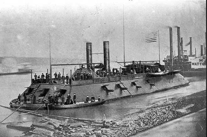
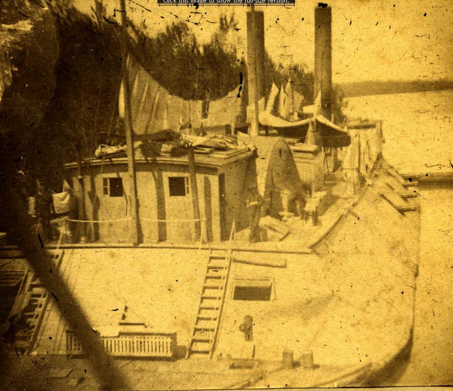
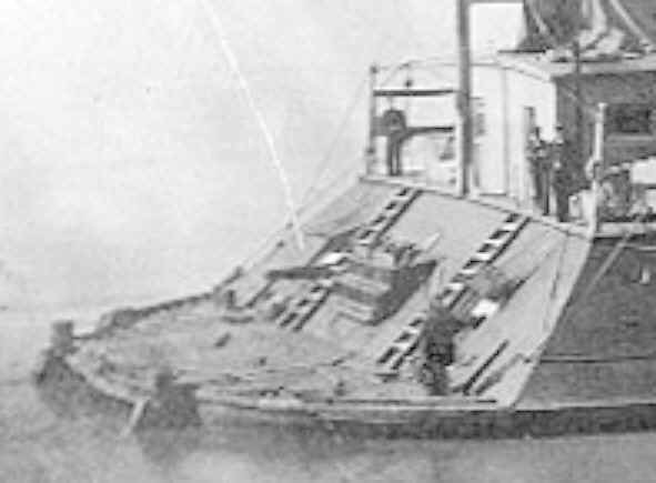
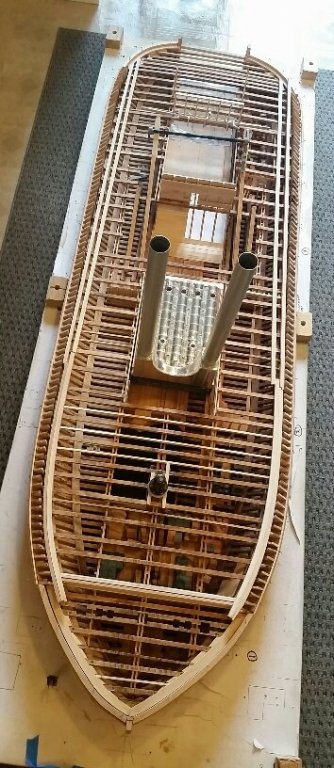
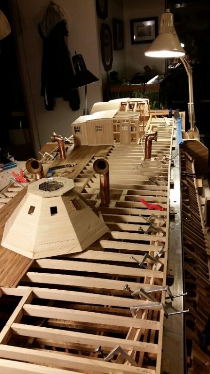
Model Enthusiasts, While building our detailed model of the "USS St. Louis" ironclad, two problems about its basic design have consistently bothered us: 1) How did a crew of 175 access the upper (Hurricane) deck ?, and 2) How were stores, equipment and provisions loaded into the cramped spaces of the lower hull?. Attached are a few contemporary photographs of "City Class" Ironclads and comparable photos of our model which better illustrate this issue. The existing drawings of "City Class" ironclads only show a single hatchway in the Hurricane deck with a ladder down to the gun deck but it is inside of the pilothouse which has no exit onto the deck itself. There are several "so-called skylights" on the Hurricane deck but only the 4' x 6' opening at the front of this deck is usable, but it is directly above the center bow casement cannon. The large "skylight" over the boilers is really an iron grate covered exhaust ventilator, and the other 2 openings are over the "Pittman" Arms and paddle wheel bellcranks. None of them have ladders or stairways. The most obvious access to the Hurricane deck would be thru open gunports onto the fore & aft decks and then up ladders on the fore & aft casements. The Captains access from his quarters on the gun deck to the Hurricane deck would evidently be thru a stern casement open gunport onto the stern deck and up a ladder on the stern casement! You can imagine the difficulty frequent coaling resupply operations with these limitations. Obviously the Hurricane deck is only an unarmored wood beam structure which could be modified for better access but since none of it survived the USS Cairo recovery in 1963, we have no idea what it may have contained. We have unsuccessfully researched this issue including the USS St. Louis log book (quasi-diary) for a better understanding and would appreciate any feedback you can provide. johnhoward


-
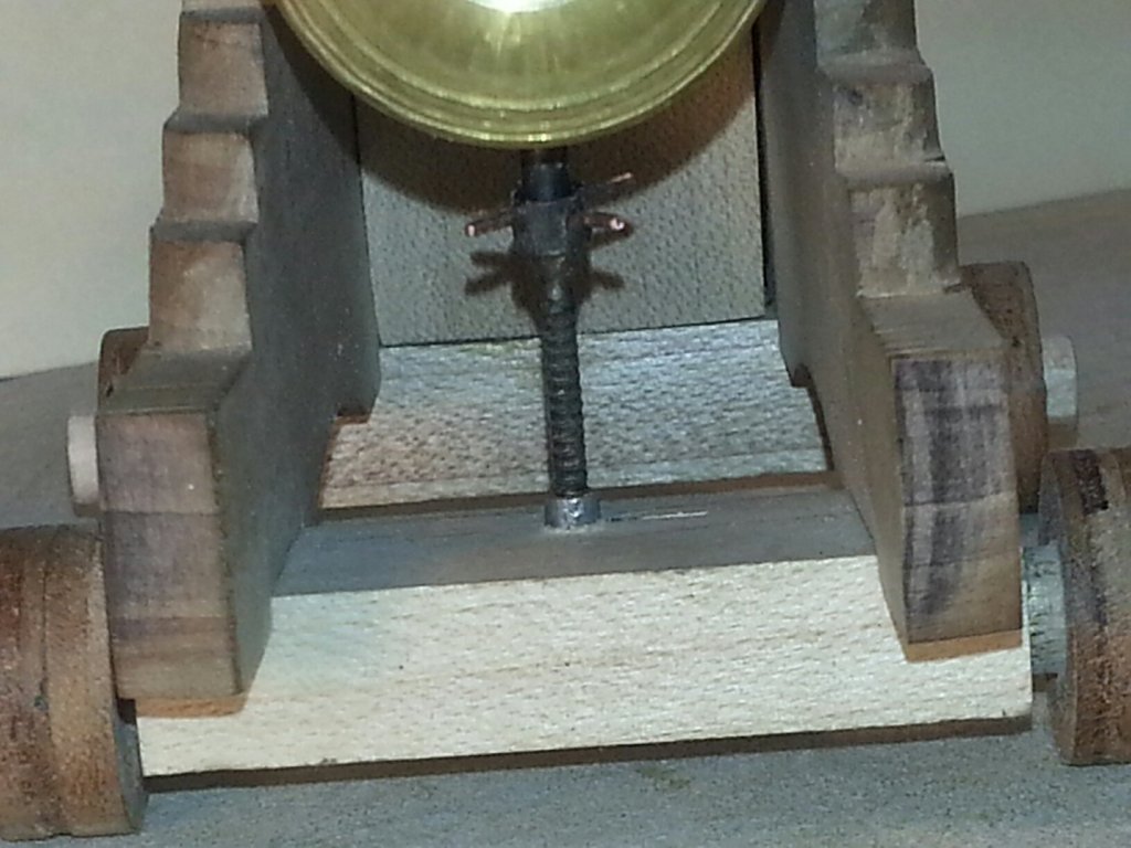
Attached are a few photos of our first unfinished brass version of the 42-pdr Rifle and Carriage with elevating screw, of which two were carried on the USS St. Louis ironclad. The other cannon in the proto are the 30-pdr Parrott & 32-pdr Smoothbore using our original 3-D printed barrel prototypes which will soon be replaced by machined brass versions. The USS St. Louis carried two 30-pdr Parrots and six 32-pdr Smoothbores. Not shown are the three 8-inch Smoothbores which will complete the main armament on the gundeck. johnhoward
.thumb.jpg.c03dc841285ccb5d2b2a5a7a882e7aa0.jpg)

-
Attached are a few recent photos depicting further progress on the wheelhouse and the framing for the ironclad starboard and aft casements. We are now starting the initial planning for modeling of the two main steam engines. johnhoward


_resized.jpg.32b08d99a181a3b029ace6693aa05bff.jpg)


.jpg.a05f2cdaaf70eb63453101ad055b7211.jpg)


.jpg.81b020ebd040f0583bcffc232d6cf956.jpg)


.jpg.6ad096f189c592fad2a95e093f8d9a01.jpg)